Overview of 3DEP Lidar Specification and Products - DRCOG |
32
Overview of 3DEP Lidar Specification and Products Presented By: Jason Caldwell Vice President of Business Development and Sales Jared Martin, CP, CMS, CST Lidar Department Manager © 2019, The Sanborn Map Company, Inc. Privileged and confidential information. Distribution or copying prohibited unless approved in writing.
-
Upload
khangminh22 -
Category
Documents
-
view
0 -
download
0
Transcript of Overview of 3DEP Lidar Specification and Products - DRCOG |

Overview of 3DEP LidarSpecification and ProductsPresented By:
Jason CaldwellVice President of Business Development and Sales
Jared Martin, CP, CMS, CSTLidar Department Manager
© 2019, The Sanborn Map Company, Inc. Privileged and confidential information.
Distribution or copying prohibited unless approved in writing.

2
Agenda
• Sanborn Overview
• Cost Drivers
• USGS Lidar Base Specifications
• Added Value Data Products
• Questions

3
Extensive Experience with Geospatial Technologies• Ground Survey since 1866
• Aerial Survey since 1966
• Digital photogrammetric mapping since 1979
• Digital terrain modeling since 1984
• First commercially digital ortho 1988
• Lidar collection and production since 1998
• Hydro conditioned Lidar DEMs since 2002
• Offered Web Service in 2004
• Digital aerial imagery sensors since 2004
• Mobile and Ground Lidar since 2010
• Oblique imagery since 2012
• Drone based imagery 2013
1/16/2019
USGS GPSC Prime Contract Holder
Completed multiple large lidar contracts:
• City and County Denver
• USGS DNC
• El Paso County
• State of Arkansas
• State of Michigan
• State of Connecticut
• State of Virginia
• State of Maryland
• State of Kanas
• State of Wyoming
• State of New York

USGS Lidar Base Specifications
• USGS first publication 2012
• Updated most recently in 2018
• Generally accepted guidelines by all federal agencies
• Aligned FEMA, ASPRS and USGS under one specification
• http://pubs.usgs.gov/tm/11b4/pdf/tm11-B4.pdf
1/16/2019 ©2013, The Sanborn Map Company, Inc.4

USGS Lidar Base Specifications: Required Deliverables
• Classified Lidar Point Cloud
• Bare-Earth Digital Elevation Model
• First Return Intensity Raster
• Breaklines
• FGDC Metadata
5
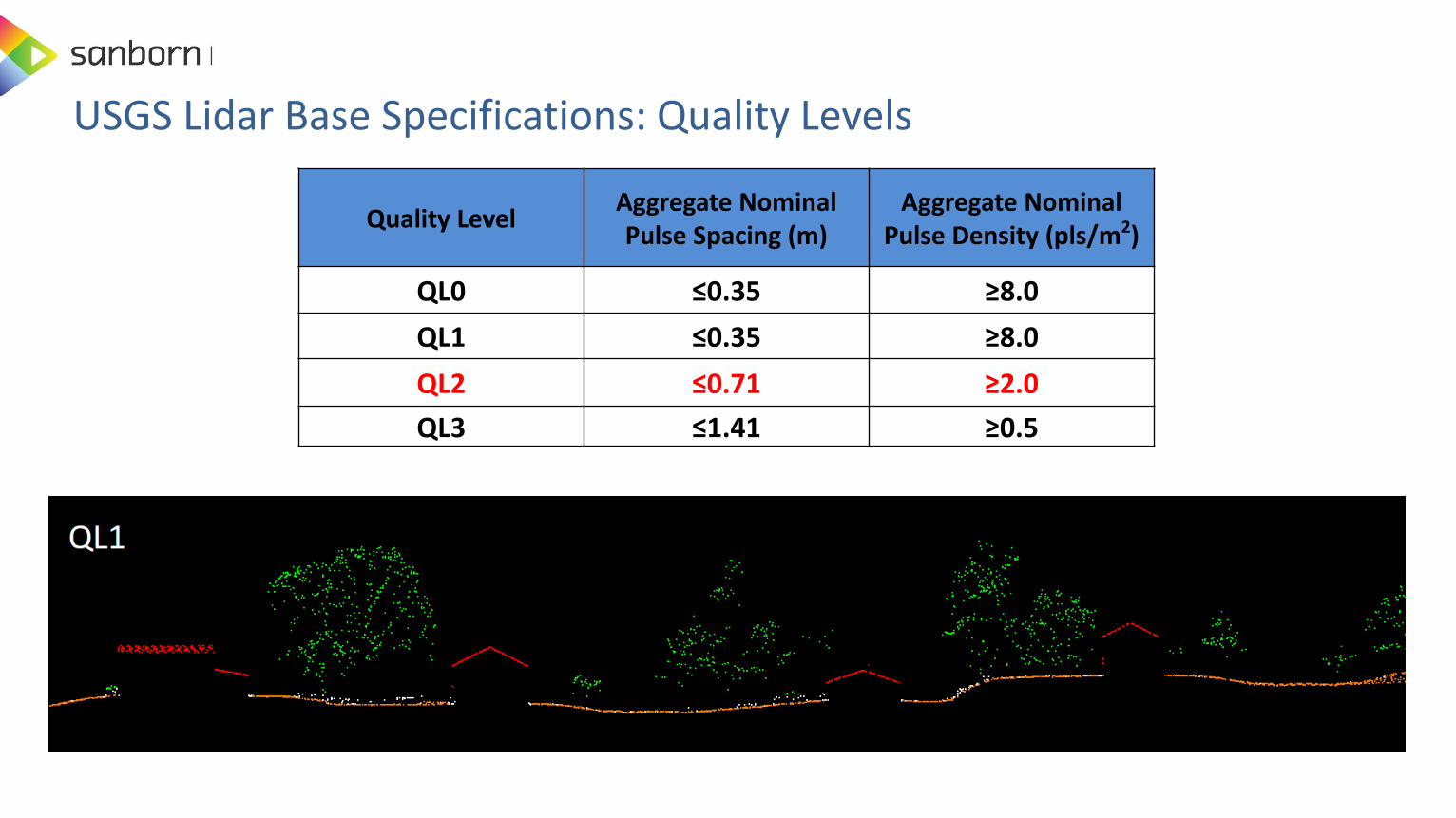
USGS Lidar Base Specifications: Quality Levels
Quality LevelAggregate Nominal Pulse Spacing (m)
Aggregate Nominal Pulse Density (pls/m2)
QL0 ≤0.35 ≥8.0
QL1 ≤0.35 ≥8.0
QL2 ≤0.71 ≥2.0
QL3 ≤1.41 ≥0.5

• All deliveries to LAS specification version 1.4-R13 (ASPRS, 2011) Point Data Record Format (PDRF 6,7,8,9,10)
• Overlap and Withheld Bit Flag Assigned• USGS LBS v1.3 - New Classes 20, 21, 22
Code Description
1 Processed, but unclassified
2 Bare earth
7 Low noise
9 Water
17 Bridge deck
18 High noise
20Ignored ground
(typically breakline proximity)
21Snow
(if present and identifiable)
22Temporal exclusion
(typically nonfavored data in intertidal zones)
USGS Lidar Base Specifications: Base Classification Levels (Additional classification can be defined)

Quality LevelRMSEZ (non-vegetated)
(m)
NVA at 95-percentconfidence level
(m)
VVA at the 95thpercentile
(m)
QL0 ≤ 0.050 ≤ 0.098 ≤ 0.150
QL1 ≤ 0.100 ≤ 0.196 ≤ 0.300
QL2 ≤ 0.100 ≤ 0.196 ≤ 0.300
QL3 ≤ 0.200 ≤ 0.392 ≤ 0.600
USGS Lidar Base Specifications: Absolute Accuracy
• Horizontal error in lidar derived elevation data is largely a function of positional error as derived from the Global Navigation Satellite System (GNSS), attitude (angular orientation) error (as derived from the INS) and flying altitude.

Quality LevelSmooth surface
repeatability,RMSDZ (m)
Swath overlapdifference, RMSDZ
(m)
QL0 ≤0.03 ≤0.04
QL1 ≤0.06 ≤0.08
QL2 ≤0.06 ≤0.08
QL3 ≤0.12 ≤0.16
• USGS is still researching methodologies for assessing relative horizontal swath-to-swath accuracy
USGS Lidar Base Specifications: Relative Accuracy

Land Cover or DescriptionPrevious
Reporting group
Broad Land Cover Category
Open terrain/bare earth, short grass; e.g. sand, rock, dirt, plowed fields, lawns, golf courses
FVANVA
Urban areas; asphalt or concrete SVA
Tall grass, tall weeds, and crops; e.g. hay, corn, and wheat fields
SVA
VVABrush lands and short trees; e.g. chaparrals, mesquite SVA
Forested areas, covered by trees; e.g. hardwoods, conifers, mixed forests
SVA
TINCONTOURS
MASSPOINTS
CHECK
POINTUSGS Lidar Base Specifications: Accuracy Assessment
• The check points should be well distributed
• All major land cover types should be well represented
• Approximately 50% of NVA points should be identifiable within the lidar intensity data

Project Area (Square Kilometers)
Vertical and Horizontal Accuracy Testing of Elevation Data sets
Number of Static 3D Check Points in NVA
Number of Static 3D Check Points in VVA
Total Number of Static 3D Check Points
<500 20 5 25
201-750 20 10 30
751-1000 25 15 40
1001-1250 30 20 50
1251-1500 35 25 60
1501-1750 40 30 70
1751-2000 45 35 80
2001-2250 50 40 90
2251-2500 55 45 100
TINCONTOURS
MASSPOINTS
CHECK
POINTUSGS Lidar Base Specifications: Accuracy Assessment
• Check points based on ASPRS Positional Accuracy Standard
• FVA, SVA and CVA has been replaced with NVA and VVA
• Number of check points is based on the total area of the project
• USGS does not provide standard for testing horizontal accuracy of lidar

USGS Lidar Base Specifications: Accuracy Assessment
• For vertical testing of areas >2,500 km2, add five additional vertical checkpoints for each additional 500 km2 area. Each additional set of five vertical checkpoints for 500 km2 would include three checkpoints for NVA and two for VVA.
• Denver encompasses 5,000 mi² and would require a total of 205 check points
– 118 NVA + 87 VVA
1/16/2019 12
TINCONTOURS
MASSPOINTS
CHECK
POINT

Quality Level Minimum cell size (m) Minimum cell size (ft)
QL0 0.5 1
QL1 0.5 1
QL2 1 2
QL3 2 5
USGS Lidar Base Specifications: Digital Elevation Model Raster Cell Size

USGS Lidar Base Specifications: Hydro Flattening/Enforcement
• USGS typically only requires hydro flattening
• No changes in the tolerances of double-line streams and water-bodies
– 100 ft. wide rivers/streams, 2 acre water-bodies
– Client can provide there own specification for small hydro features

USGS Lidar Base Specifications: Hydro Flattening Vs. Enforcement
• Hydro-flattened describes the specific type of DEM required by the USGS National Geospatial Program (NGP) for integration into the NED.
• A traditional topographic DEM such as the NED represents the actual ground surface, and hydrologic features are handled in established ways.
• In HF surface roadways crossing drainages passing through culverts remain in the surface model because they are part of the landscape (the culvert beneath the road is the manmade feature). Bridges, manmade structures above the landscape, are removed.
– In HF: Terrain topography gets preference
– In HE: Hydro-features get preference over terrain features

USGS Lidar Base Specifications: Hydro Flattened Breaklines

USGS Lidar Base Specifications: Hydro Flattened
Monotonicity (downhill order) Flat Water Bodies

• DEM created only using Bare-Earth Lidar points.
• Water surface contains extensive triangulation artifacts (“tinning”) caused by the absence of lidar returns.
• Breakline constraints define buildings, water, and other features.
• Aesthetically and cartographically unacceptable to most users.
Triangulation in Water
USGS Lidar Base Specifications: Bare Earth Lidar, No Hydro Breaklines

• Removes the most offensive pure lidarartifacts: those in the water. Constant shore elevation for water bodies.
• Wide streams and rivers are flattened bank-to-bank and forced to flow downhill (monotonicity).
• Carries ZERO implicit or explicit accuracy with regards to the represented water surface elevations –Typically used for Cartographic/Aesthetic enhancement.
• Most often achieved via the development and inclusion of hard breaklines.
Water Body Stream
USGS Lidar Base Specifications: Hydro Flattened, Topographic Surface

USGS Lidar Base Specifications: Hydro Enforced Hydrologic Surface
• Surface used by engineers in Hydraulic and Hydrologic (H&H) modeling.
• NOT to be used for traditional mapping (contours, etc.)
• Similar to Hydro Flattened with the addition of Single Line Breaklines: Pipelines, Culverts, Underground Streams, etc…
• Terrain is then cut away at bridges and culverts to model drain connectivity.
• Water Surface Elevations are often set to known values typically from surveying methods.
Culverts Cut Through Roads

USGS Lidar Base Specifications: Required Deliverables
• Classified Lidar Point Cloud
• Bare-Earth Digital Elevation Model
• First Return Intensity Raster
• Breaklines
• FGDC Metadata
21

Added Value Derivative Products/Services
• Additional Elevation Products
– Additional Point Density
– Additional Point Classification
– Digital Surface Model
– Contours
– RGB Fusion
– Change Detection
22

Do I Need Higher Density Lidar?• Higher density lidar is typically used for one of two reasons
– Better penetration to ground in dense vegetated areas
– Feature extraction use cases require more density for feature identification
• Horizontal density does not improve ground accuracy
• Use cases for higher density data include:– Forestry applications
– Above ground utility infrastructure mapping
– 3D building feature extraction (solar assessment modeling)
– Transportation based asset inventories (signs, guardrails, bill boards)
– Transportation based surface conditions
1/16/2019 23

1/16/2019 24

Enhanced Lidar Point Cloud Classification
• The classification process discriminates raw lidar points into defined categories
• The objective for USGS LBS v1.3 is mainly to separate ground points from non-ground points
• Custom, enhanced classification schemes can discriminate buildings, vegetation, etc.
• Cost is function of complexity of classification scheme and feature density.
25
USGS LBS v1.3
Classification Requirement
Class 1 Processed, but unclassified
Class 2 Bare earth
Class 7 Low noise
Class 9 Water
Class 17 Bridge deck
Class 18 High noise
Class 18 High noise
Class 20 Ignored ground
Class 21 Snow
Class 22 Temporal exclusion
Sample
Enhanced ClassificationsClass 3 Low Vegetation
Class 4 Medium Vegetation
Class 5 High Vegetation
Class 6 Building

Enhanced Lidar Point Cloud Classification
26

Lidar Digital Surface Model (DSM)
• A DSM represents the first return or first strike of all lidar points
• Includes all above ground features, as well as unobstructed terrain
• Line of site analysis, wireless signal propagation, airport obstruction studies

• Contours are derived from the lidar DTM and enhanced through the addition of breaklines at significant terrain breaks
Contours
28
Contours without hydro breaklines Contours with hydro breaklines and smoothing

RGB Fusion
1/16/2019©2013, The Sanborn Map Company, Inc. 29

RGB Fusion
1/16/2019©2013, The Sanborn Map Company, Inc. 30

Sanborn Change Detection Viewer
1/16/2019 31
Toggle between main and side windows
Change metadata(sortable) Layers
Search
Mark true/false positive changes

Questions