Optically transparent multiple access networks employing ...

Optically multiplexed imaging withsuperposition space tracking
Shikhar Uttam1,Nathan A. Goodman1 and Mark A. Neifeld1,2
Changsoon Kim3,Renu John3,Jungsang Kim3,and David Brady3
Dept. of Electrical and Computer Engineering1,The Optical Sciences Center2, University ofArizona
Dept. of Electrical and Computer Engineering, Duke University3
Abstract: We describe a novel method to track targets in a large fieldof view. This method simultaneously images multiple, encoded sub-fieldsof view onto a common focal plane. Sub-field encoding enablestargettracking by creating a unique connection between target characteristicsin superposition space and the target’s true position in real space. Thisis accomplished without reconstructing a conventional image of the largefield of view. Potential encoding schemes include spatial shift, rotation, andmagnification. We discuss each of these encoding schemes, but the mainemphasis of the paper and all examples are based on one-dimensional spatialshift encoding. System performance is evaluated in terms oftwo criteria:average decoding time and probability of decoding error. Westudy theseperformance criteria as a function of resolution in the encoding schemeand signal-to-noise ratio. Finally, we include simulationand experimentalresults demonstrating our novel tracking method.
© 2009 Optical Society of AmericaOCIS codes: (110.1758) Computational imaging; (280.0280) Remote sensingand sensors;(100.4999) Pattern recognition, target tracking
References and links1. E. Cuevas, D. Zaldivar, and R. Rojas, “Kalman filter for vision tracking,” Free University of Berlin, Tech. Rep.,
(2005).2. D. J. Brady, “Micro-optics and megapixels,” Optics and Photonics News17, 24–29, (2006).3. D. J. Brady and M. E. Gehm, “Compressive imaging spectrometersusing coded apertures,” Proc. SPIE6246,
62460A, (2006).4. M. A. Neifeld and P. Shankar, “Feature-specific imaging,” Appl. Opt.42, 3379–3389, (2003).5. D. Takhar, J. N. Laska, M. B. Wakin, M. F. Duarte, D. Baron, S. Sarvotham, K. F. Kelly, and R. G. Baraniuk,
“A new compressive imaging camera architecture using optical-domain compression,” Proc. SPIE6065, 606509,(2006).
6. D. Donoho, “Compressed sensing,” IEEE Trans. Inform. Theory 52, 1289–1306, (2006).7. E. J. Candes, “Compressive sampling,” Proc. of the Intl. Cong. of Mathematicians, (2006).8. M. D. Stenner, P. Shankar, and M. A. Neifeld, “Wide-field feature-specific imaging,” in Frontiers in Optics,
Optical Society of America, (2007).9. D. Du and F. Hwang, Combinatorial group testing and its applications, Series on Applied Mathematics12, (World
Scientific, 2000).10. C. M. Brown, “Multiplex imaging with random arrays,” Ph.D. dissertation, Univ. of Chicago, (1972).11. R. H. Dicke, “Scatter-hole cameras for x-rays and gamma rays,” Astrophys J.153, L101–L106,(1968).12. A. Biswas, P. Guha, A. Mukerjee, and K. S. Venkatesh, “Intrusion detection and tracking with pan-tilt cameras,”
IET Intl. Conf. VIE 06 , 565–571, (2006)13. A. W. Senior, A. Hampapur, and M. Lu, “Image segmentation in video sequences: A probabilistic approach,”
WACV/MOTION’05, 433–438, (2005)
#99244 - $15.00 USD Received 25 Jul 2008; revised 27 Oct 2008; accepted 19 Jan 2009; published 29 Jan 2009
(C) 2009 OSA 2 February 2009 / Vol. 17, No. 3 / OPTICS EXPRESS 1691

14. C. R. Wren, A. Azarbayejani, T. J. Darrell, and A. P. Pentland, “Pfinder: Real-time tracking of the human body,”IEEE Trans. Pattern Anal. Mach. Intell19, 780–785, (1997)
15. N. Friedman and S. J. Russell, “Image segmentation in video sequences: A probabilistic approach,” Proc. Uncer-tainty Artif. Intell. Conf., 175–181, (1997)
16. C. Stauffer and E. L. Grimson “Learning patterns of activity using real-time tracking,” IEEE Trans. Pattern Anal.Mach. Intell22, 747–757, (2000)
17. A. Mittal and N. Paragios, “Motion-based background subtraction using adaptive kernel density estimation,”Proc. IEEE Conf. Comput. Vis. Pattern Recognit., 302–309, (2004).
18. K. P. Karmann and A. Brandt, ”Moving Object Recognition Using an Adaptive Background Memory,” in Timevarying image processing and moving object recognition Volume2, V. Cappellini (ed.), (Elsevier, 1990).
19. P. Jodoin, M. Mignotte, and J. Konrad, “Statistical background subtraction using spatial cues,” IEEE CircuitsSyst. Video Technol17, 1758–1763, (2007).
20. R. Singh, “Advanced correlation filters for multi-class synthetic aperture radar detection and classification,”Carnegie Mellon University, MS Rep., (2002).
21. M. Alkanhal and B. V. K. Vijaya Kumar, “Polynomial DistanceClassifier Correlation Filter for Pattern Recogni-tion,” Appl. Opt.42, 4688–4708, (2003).
22. B. V. K. Vijaya Kumar, “Minimum-variance synthetic discriminant functions,” J. Opt. Soc. Am. A3, 1579–1584,(1986).
23. B. V. K. Vijaya Kumar, D. W. Carlson and A. Mahalanobis, “Optimal trade-off synthetic discriminant functionfilters for arbitrary devices,” Optics Letters19, 1556–1558, (1994).
24. S. M. Kay,Fundamentals of Statistical Processing, Volume I: Estimation Theory. (Prentice Hall, 1993).
1. Introduction
There are numerous applications that require visible and/or infrared surveillance over a largefield of view (FOV). The requirement for large FOV frequentlyarises in the context of securityand/or situational awareness applications in both military and commercial domains. A commonchallenge associated with large FOV concerns the high cost of the required imagers. Imager costcan be classified into two categories: sensor costs and lens/optics costs. Sensor costs such asfocal plane array (FPA) yield (i.e., related to pixel count), electrical power dissipation, trans-mission bandwidth requirements (e.g., for remote wirelessapplications), etc. all increase withFOV. Some of these scalings are quite severe, with process yield for example increasing ex-ponentially with FOV. Optics costs such as size (i.e., totaltrack), complexity (e.g., number ofelements and/or aspheres), and mass also increase nonlinearly with FOV; however, these costsare somewhat more difficult to quantify without undertakingdetailed optical designs. However,to illustrate the point consider two commercial lenses fromCanon: the Canon EF 14mm f/2.8LII USM and the Cannon EF 50mm f/1.8 II lenses. The former is a wide-angle lens (FOV = 114degrees) while the latter is a standard-angle lens. The wide-angle lens requires more opticalelements and a sophisticated design to maintain resolutionover the field of view. As a result,the wide-angle lens uses 14 optical elements and weights 645grams while the standard-anglelens uses 6 optical elements and weights 130 grams.
We note that the various costs associated with a conventional approach to wide-FOV imagingoften prohibit deployment of such imagers on platforms of interest. For example, the highmass cost together with the electrical power and bandwidth costs of conventional widefieldimagers, restrict their application on many UAV platforms.Therefore, the motivation of thework reported here is to reduce the various costs of widefieldsurveillance, thus making itfeasible for more widespread deployment.
One typical solution to this problem involves the use of narrow FOV pan/tilt cameras whosemechanical components often come with the associated costsof increased size, weight, andpower consumption. The pan/tilt solution also sacrifices continuous coverage in exchange forreduced optical complexity. In most traditional approaches the goal in such problems is toreconstruct the scene of interest.
Many imaging applications, however, do not require the production of a traditional imagerepresentation (i.e., a pretty picture) suitable for humanconsumption. In these so-called task-
#99244 - $15.00 USD Received 25 Jul 2008; revised 27 Oct 2008; accepted 19 Jan 2009; published 29 Jan 2009
(C) 2009 OSA 2 February 2009 / Vol. 17, No. 3 / OPTICS EXPRESS 1692

specific imagers, it is the effectiveness of the exploitation algorithm operating on the sensoroutput that determines overall system performance. For example, an access control imager(e.g., fingerprint sensor) may never provide image data for visual inspection. The success ofthis imager is entirely determined by how well it facilitates reliable matching (e.g., fingerprintrecognition). Another example is tracking, in which measured image data is used to identifytarget locations. The success of this imager is determined only by the accuracy of the targetpositions that emerge from the associated postprocessing algorithm (e.g., Kalman filter [1]).
Task-specific imagers can often be compressive, in that theyrequire many fewer measure-ments than the native dimension of the object space. Compressive imaging has emerged as apromising paradigm for improving imager performance and/or reducing imager resources [2],[3], [4], [5]. As a special case of compressive sensing, compressive imaging benefits from manyimportant recent theoretical results from that domain [6],[7]. The goal of this paper is to applyconcepts from compressive sensing and task-specific imaging to the problem of continuouslytracking targets over a large FOV. Toward this end we proposea class of task-specific mul-tiplexed imagers to collect encoded data in a lower-dimensional measurement space we callsuperposition space and develop a decoding algorithm that tracks targets directly in this super-position space. We discuss the multiplexed imagers in the next section. For now, we assumethat we have this ability and briefly explain the basic idea behind superposition space tracking,which is the main focus of this paper.
We begin by treating the large FOV as a set of small sub-FOVs (disjoint sub-regions ofthe large FOV). All sub-FOVs are simultaneously imaged ontoa common focal plane array(FPA) using a multiplexed imager. The multiple lens system of Fig. 1 is a schematic depictionof this operation. Lens shutters can also be used to control whether individual sub-FOVs areturned on, though for clarity the shutters are not drawn in Fig. 1. The measurement thereforeis a superposition of certain sub-FOVs. A key feature of our work is applying a unique encod-ing for each sub-FOV, which facilitates target tracking directly on the measured superimposeddata. Potential encoding schemes include (a) spatial shift, (b) rotation, (c) magnification, and/orcombinations of these. These encoding methods are schematically depicted in Fig. 2.
Fig. 1. Multiple lenses camera capable of performing both pan/tilt and multiplexed opera-tions.
Encoding via spatial shifts is perhaps the easiest encodingscheme to visualize; therefore,we use this scheme for the demonstrations and performance results presented in this paper.In spatial-shift encoding, each sub-FOV is assigned a shiftsuch that it overlaps adjacent sub-FOVs by a specified, unique amount. These spatial shifts can be one dimensional (1-D) or twodimensional (2-D). In the 1-D case, the large FOV is sub-divided along one dimension intosmaller sub-FOVs. In the 2-D case, as illustrated in Fig 2(a), the full FOV is sub-divided in twoorthogonal directions. Therefore, the 2-D case can be thought of as two separable 1-D cases
#99244 - $15.00 USD Received 25 Jul 2008; revised 27 Oct 2008; accepted 19 Jan 2009; published 29 Jan 2009
(C) 2009 OSA 2 February 2009 / Vol. 17, No. 3 / OPTICS EXPRESS 1693

with decoding information shared between the two.Rotational encoding (Fig 2(b)) assigns different rotations to each sub-FOV such that a target
undergoes an angular shift in the superimposed image when itcrosses between two sub-FOVs.The rotational difference between any two adjacent sub-FOVs must be unique. In a similarmanner, as shown in Fig 2(c), magnification encoding assignsa unique magnification to eachsub-FOV such that changes in the target’s apparent size can be used to properly determine itslocation.
In this work we focus on 1-D spatial shift encoding due to its relative ease of implementa-tion, easier visualization and proof-of-concept explanation, and its straightforward extension tothe 2-D case. The decoding process refers to the algorithm applied to determine a target’s truelocation in object space. We begin in Section 2 by proposing candidate optical architecturesfor multiplexed imagers. In Section 3 we outline the methodology for 1-D spatial shift encod-ing and provide a brief discussion of other encoding techniques. Section 4 provides proof-of-concept examples and explanations for the target decoding procedure while Section 5 containsdemonstration and performance analysis via simulated and experimental data. We make ourconclusions in Section 6.
Fig. 2. Schematic representation of encoding schemes: (a) Spatial shift (two-dimensionalcase shown), (b) rotation, and (c) magnification.
2. Candidate multiplexed optical architectures
Previously we have reported on the capabilities of a novel multiplexed camera that employsmultiple lenses imaging onto a common focal plane [8]. A schematic depiction of this multi-aperture camera is shown in Fig. 1. Note that each lens can have a dedicated shutter (not shown).In this camera each lens images a separate region (i.e., a sub-FOV) within the full FOV. Byappropriate choice of shutter configurations, various modes of operation are possible. In onesuch mode all shutters are opened in sequence (one at a time),enabling an emulation of pan/tiltoperation. Another mode of operation allows multiple shutters to be open at a time. This modeemploys group testing concepts in order to measure various superpositions of sub-FOVs andinvert the resulting multiplexed measurements to obtain a high-quality reconstructed image [2],[9], [10], [3], [11]. The third mode allows all the shutters to be open at the same time resultingin superposition of all sub-FOVs onto the common FPA.
Another optical implementation is shown in Fig. 3, in which we employ beamsplitter andmirror combinations to form the superposition measurements. This configuration reduces thelens count and avoids the image-plane tilt associated with the configuration shown in Fig. 1.
#99244 - $15.00 USD Received 25 Jul 2008; revised 27 Oct 2008; accepted 19 Jan 2009; published 29 Jan 2009
(C) 2009 OSA 2 February 2009 / Vol. 17, No. 3 / OPTICS EXPRESS 1694

Figure 3(a) shows a setup for two sub-FOVs consisting of a beamsplitter and a movable mirror,which serves as a building block for a larger system. The optical field from the left sub-FOV( f ov1) is reflected by the mirror followed by the beamsplitter, andthen is merged with the opti-cal field from the right sub-FOV (f ov2) that has passed through the beamsplitter. The rotation ofthe mirror around thez-axis results in the translation off ov1 along thex-direction in superposi-tion space, providing a means to control the overlap betweenf ov1 and f ov2. Figure 3(b) showsan assembly of such building blocks, which can superimpose eight sub-FOVs. This implemen-tation will serve as the basis for the experimental results presented later in sub-section 5.4.
A third implementation shown in Fig. 4 further refines the idea proposed in the second im-plementation by using a binary combiner in a logarithmic sequence arrangement. If we con-sider the same eight sub-FOVs as in Fig. 3(b), then this design allows us to access all eightsub-FOVs, using three stages of single-plate beamsplitter/mirror pairs at each stage, and threeshutters placed on the mirrors. The shutters can be opened and closed in a binary sequence from000 (all closed) to 111 (all open, superposition operation)to multiplex the eight sub-FOVs ontothe camera. Although the effective aperture of the plate beamsplitter and mirror combinationincreases at each stage, there is an overall reduction in complexity in comparison to the opticalimplementation shown in Fig. 3(b). For a general scenario, when the large angular FOV isφradians and each angular sub-FOV is given byβ radians, the number of stages in the binarycombiner is given byS= ⌈log2 φ/β⌉ and the front end effective apertureAe required to avoidvignetting is approximately given by
Ae = 2A(1− tanφ4
)−1(1−β )−S, (1)
whereA is the aperture of the camera. To obtain this relation between effective front end aper-ture and the large angular FOV we fix the plate beamsplitter tobe at an angle ofπ/4 with respectto the vertical axis and adjust the mirror to the desired angle depending on the value ofφ . Ifwe define the angle of the mirror from the vertical to beγ, then for a givenφ , γ = (π −φ)/4.This system gives us the ability to employ a camera whose angular FOV is smaller than thelarge angular FOV by a factor of 2S. We have discussed the optical scheme in a 1-D setting, butbecause the horizontal and vertical directions are separable, extension to 2-D is straightforward.
Figure 4 illustrates this design concept with a specific example. The angles are shown indegrees for this example. The implementation is designed for eight sub-FOVs, each having anangular range ofβ = 7.5◦. For simplicity, the sub-FOVs are assumed to be non-overlapping,resulting in an angular FOV (φ ) of 60◦. The first stage folds 0◦ to −30◦ angular range onto the0◦ to 30◦ angular range. In the second stage the resulting 30◦ angular range is further halvedto a 15◦ range using a plate beamsplitter and a mirror, which are at angles of 45◦ and 52.5◦
from the vertical axis. The third stage again halves the 15◦ range to 7.5◦ which is the range of asingle sub-FOV. For the third stage the plate beamsplitter and mirror angles are 45◦ and 48.75◦,respectively. If the sub-FOVs are overlapped, then the angles of the mirrors in each stage canbe adjusted to implement the given overlap.
As the angular FOV at the end of this three-stage binary combiner is reduced by a factor of 23
to 7.5◦, we can use a simple lens at the end of this optical setup. We consider the TECHSPECMgF2 coated achromatic doublet with a diameter of 12.5mm anda focal length of 35mm. GivenA = 12.5mm, using (1) we calculate the front end effective apertureAe of the beamsplitter andmirror combination to be 5.2cm. Since the optical system does 2-D imaging we have the samethree-stage binary combiner in the other dimension with thesame effective front end aperture.In total therefore, we have six plate beamsplitter and mirror combinations. Assuming, for sim-plicity, that the beamsplitter and the mirror equally sharethe effective aperture, the lengths ofthe plate beamsplitter and the mirror are given by(5.2/2)
√2cm and(5.2/2)(2/
√3)cm. The
factors of√
2 and 2/√
3 follow from the plate beamsplitter and the mirror being at angles of
#99244 - $15.00 USD Received 25 Jul 2008; revised 27 Oct 2008; accepted 19 Jan 2009; published 29 Jan 2009
(C) 2009 OSA 2 February 2009 / Vol. 17, No. 3 / OPTICS EXPRESS 1695

45◦ and 30◦ respectively from the vertical axis . Assuming a square sizefor both, the Stage 3dimensions of the plate beamsplitter are 3.7cm×3.7cm and that of the mirror are 3cm×3cm.Also assuming the thickness of the optical glass to be 2mm, wecalculate that in Stage 1 thetotal volume of glass used by the two pairs (corresponding to2-D imaging) of plate beamsplit-ter and mirror combination is 9.1cm3. Doing similar calculations for Stages 2 and 3 gives thevolume of glass used to be 6.8cm3 and 4cm3, respectively. If we take the density of the opticalglass to be 2.5gm/cm3, the total mass of the log combiner is 49.75gm. The mass of theachro-matic doublet is less than 5gm and hence the weight of the optical system is about 54.75gm. Ifwe were to directly use a wide-angle lens to capture an angular FOV of 60◦, then a potentialcandidate is Canon’s EF 35mm f/1.4L USM lens. It has an angular FOV of 63◦, but its mass is580 gm and it uses 11 optical elements. Therefore, we see savings of about a factor of 10 forour proposed multiplexed imager and also reduced optical complexity as we are using a sim-ple, easy-to-design binary combiner and an achromatic doublet as opposed to an 11-elementwide-angle lens.
camera camera
(a) (b)
mirror beamsplitter
f ov1 f ov2
x
y
z
Fig. 3. Optical setup capable of performing multiplexed operations with spatial shift en-coding for (a)Ns = 2 and (b)Ns = 8
Two practical issues that arise in designing optical systems involving beamsplitters are vi-gnetting and transmission loss. Vignetting arises when there is non-uniformity in the amountof light that passes through the optical system for each of the points in the FOV. This resultingnon-uniformity at the periphery of the superposition data has the potential of increasing falsenegatives which in turn can lead to errors in properly locating the targets. To overcome thispotential problem in the setup shown in Fig. 3, the size of each beamsplitter should be largeenough to ensure that the angular range subtended by that beamsplitter at the camera is a strictupper bound on the angular range of the corresponding sub-FOV. Field stops are then used torestrict the angular range of the beamsplitter to that of thesub-FOV. Specifically, for the setupshown in Fig. 3 and used in Section 5.4, each sub-FOV is 1.9◦ horizontally and 1.3◦ verti-cally while the angular range of the beamsplitter is approximately 3◦. As a result, vignettingis avoided. For the binary combiner shown in Fig. 4 vignetting is not an issue because (1) isderived from a vignetting analysis of the binary combiner, to give an effective apertureAe thatdoes not block light from any point in the large angular FOV.
#99244 - $15.00 USD Received 25 Jul 2008; revised 27 Oct 2008; accepted 19 Jan 2009; published 29 Jan 2009
(C) 2009 OSA 2 February 2009 / Vol. 17, No. 3 / OPTICS EXPRESS 1696

Fig. 4. Binary combiner in a log sequence arrangement for multiplexing 8sub-FOVs eachwith an angular range of 7.5◦.
The second issue has to do with a decrease in throughput due tooptical “combination loss”when the light passes through the various stages of the beamsplitters. Specifically for theeight sub-FOV multiplexed imager shown in Figure 3(b) the optical transmission decreases by(0.5)(0.5)(0.5) = 0.125. This throughput cost, however, isno worse than that of a narrow-fieldimager in a pan-tilt mode which is commonly used to achieve a wide FOV [12], [13]. For ourcurrent example the dwell time of a corresponding narrow-field imager on each sub-FOV willbe 1/Ns = 1/8 = 0.125 time units. Since the photon count is directly proportional to the dwelltime, we have the same photon efficiency for both the multiplexed and wide-field imagers. Thisresult can be extended to a general case ofNs sub-FOVs where the photon efficiency of boththe multiplexed and wide-field imagers is reduced by a factorof Ns. We acknowledge, however,that for the proposed beam-splitter and mirror-based multiplexed imagers we have not taken thecomponent losses, e.g. scattering at the mirror, into account. We assume these losses to be smallin comparison to the photon efficiency. Unlike the beamsplitter and mirror based multiplexedimagers, the multiple-lens-based imager shown in Fig. 1 overcomes the disadvantage of loss inphoton efficiency at the expense of a higher optical mass cost.
The imagers we have proposed are used to simultaneuosly encode and compress (throughsuperposition of the sub-FOVs) the data. The subsequent algorithm then performs target track-ing by decoding the relevant information from this compressed superpositon data. In the nextsection we discuss in detail the need for encoding and also explain the encoding methodologywith respect to 1-D spatial shifts.
3. Sub-FOV superposition and encoding
As discussed in the Introduction, our goal is to track targets over a large FOV. We suppose thislarge FOV to beH distance units in the vertical dimension byW distance units in the horizontal(encoded) dimension. The 1-D spatial shift encoding strategy is best understood by considering
#99244 - $15.00 USD Received 25 Jul 2008; revised 27 Oct 2008; accepted 19 Jan 2009; published 29 Jan 2009
(C) 2009 OSA 2 February 2009 / Vol. 17, No. 3 / OPTICS EXPRESS 1697

the following three domains or spaces we work with: object space, superposition space, andhypothesis space.
The object space is the full area on the ground that is actually observed by the sensor. For sakeof clarity, we begin by letting the sub-FOVs be uncoded. Uncoded sub-FOVs are obtained whentheH×W area of the large FOV is simply divided intoNs adjacent sub-FOVs, without overlap,as shown in Fig. 5(a). Each of the resulting sub-FOVs isH ×Wf ov in size whereWf ov = W/Ns.Using an optically multiplexed imager, we image each of these sub-FOVs onto a common FPA.If the object space resolution of the optical system is∆r distance units in each direction, thenthe dimensionality (in pixels) of a single sub-FOV will beH/∆r pixels byWf ov/∆r pixels.
Optical multiplexing of all sub-FOVs onto an FPA the size of asingle sub-FOV correspondsto superposition of all the sub-FOVs. Thus, the measured image comprises what we call the su-perposition space. Note that the superposition of all sub-FOVs onto a single FPA provides datacompression -H/∆r byW/∆r pixels are imaged using anH/∆r byWf ov/∆r-pixel FPA. Specif-ically, the compression ratio for the uncoded case being discussed isNs. Measuring only thesuperposition, however, introducesambiguityinto the target tracking process. Consider a sin-gle target moving through the first sub-FOV in the uncoded object space as shown in Fig. 5(a).The corresponding superposition space looks like Fig. 5(b). Based on the encoding used (in thiscase none) and the size of a single sub-FOV we decode possiblelocations of the target in objectspace. We call this new space the hypothesis space (see Fig. 5(c).) The hypothesis space isnota reconstruction of the object space - it is a visualization of the decoding logic.
The single target detected in the superposition space of Fig. 5(b) does not provide informa-tion about the true sub-FOV where the target is located. Therefore, there is ambiguity in thehypothesis space, and we hypothesize that the target could be in any of theNs sub-FOVs. Infact, for this uncoded case, it is not possible to correctly decode the target location based onmeasurements in superposition space. To overcome this ambiguity, we need a distinguishingcharacteristic that appears in the superposition space yetidentifies a target’s true location inobject space. This trait can be provided by encoding the sub-FOVs with a spatial shift in theobject space. Instead of defining non-overlapping sub-FOVs, we allow for some overlap be-tween adjacent sub-FOVs in the object space as seen in Fig. 6(a). In this shift-encoded system,when a target passes through an area of overlap between two ormore sub-FOVs, instead of asingle target being present in superposition space there are multiple copies of the original targetas shown in Fig. 6(b). We refer to these multiple copies asghostsof the target. The presence ofthese ghosts allows the target location to be decoded as longas the pairwise overlap betweenadjacent sub-FOVs is unique.
The overlaps can be designed in different ways. They can be random and unique such that notwo overlaps are the same, or they can be integer multiples ofa fundamental shift. Also, theseinteger multiples need not be successive, but can be randomly picked from the available set.The simplest design, however, is to let the overlaps be successive multiples of a fundamentalshift, which we call the shift resolutionδ . Given that there areNs sub-FOVs, we define theunique overlaps to be the overlap setO = {0,δ ,2δ , . . . ,(Ns− 2)δ}. We can now construct a1-D spatial-shift encoded object space as follows:
1. Start with the uncoded sub-FOVs.
2. Let the first two (from the left) sub-FOVs be in the same position (non-overlapped) as inthe uncoded case. We label these sub-FOVs asf ov0 and f ov1 respectively;
3. Shift theith sub-FOV (f ovi), i = {2, . . . ,Ns−1} to the left such that it overlaps with the(i −1)th sub-FOV byOi−1. Depending on the size of the overlap, it is possible that theshift causes portions off ovi to overlap with more than one sub-FOV. (Figure 7 is anexample.) One condition that must be satisfied is thatf ovi cannot completely overlap
#99244 - $15.00 USD Received 25 Jul 2008; revised 27 Oct 2008; accepted 19 Jan 2009; published 29 Jan 2009
(C) 2009 OSA 2 February 2009 / Vol. 17, No. 3 / OPTICS EXPRESS 1698

(a)
(b)
(c)
Fig. 5. (a) The area of interest (large FOV) for tracking targets along with the referencecoordinate system. The large FOV is sub-divided into 4 non-overlappingsub-FOVs in thex-direction. In this un-coded case the object space and the FOV are the same. (b) Super-position space. (c) Hypothesis space: From the superposition space it isnot possible totell which sub-FOV the target belongs to. This ambiguity in target location leads to thehypothesis that the target could be in any of the 4 sub-FOVs.
f ovi−1. This condition implies a restriction on the shift resolutionδ . The shift resolutioncan range from zero (uncoded) to a maximum ofδmax= Wf ov/(Ns−1).
As shown in Section 4, the resulting encoded object space enables the target location to bedecoded. The disadvantage is that the object space now covers a smaller area than the uncodedcase. The object space is largest whenδ = 0, which corresponds to an uncoded case withtarget decoding ambiguity. The object space is smallest (covers the least area) whenδ = δmax.Between these two extremes, there is a compromise between area coverage and the smallestshift resolution that must be detected in the decoding procedure.
To quantify the reduction in area coverage, we define area coverage efficiency (η) to be theratio between the area of the encoded object space and the uncoded object space. The shiftresolution also affects the compression ratio (r), which is defined as the ratio of the area ofthe encoded object space to the area of a single sub-FOV. The area coverage efficiency and thecompression ratio are given by
η = 1−α(Ns−2)
2Ns, (2)
r = Ns−α(Ns−2)
2, (3)
#99244 - $15.00 USD Received 25 Jul 2008; revised 27 Oct 2008; accepted 19 Jan 2009; published 29 Jan 2009
(C) 2009 OSA 2 February 2009 / Vol. 17, No. 3 / OPTICS EXPRESS 1699

whereα = δ/δmax lies between 0 and 1. Smallα results in better area coverage and highercompression ratio but smaller shift resolution. In addition, if we define a boundary as a line inobject space where there is a change in the sub-FOV overlap structure, then small alpha alsoresults in a lower boundary density, which can adversely affect the average time required toproperly decode a target. The opposite characteristics aretrue for values ofα near unity. Wequantify trade-offs between area coverage, decoding accuracy, and average decoding time inmore detail in Section 5.
3.1. 2-D spatial, rotational and magnification encodings
Although 1-D spatial shift encoding is the main focus of thispaper, we now take time to brieflydescribe other potential encoding schemes.
As mentioned previously, 2-D spatial shift encoding can be thought of as two separable 1-Dspatial shift encodings. Specifically, instead of sub-dividing the large FOV into smaller sub-FOVs in only thex-direction, we also sub-divide in they-direction. Again starting with theuncoded case, if the number of sub-FOVs in the two directionsareNx andNy respectively, thesize of each resulting sub-FOV isH f ov×Wf ov whereH f ov = H/Ny andWf ov =W/Nx. Definingthe shift resolutions in the two dimensions asδx and δy, the overlap sets are then given byOx = {0,δx,2δx, . . . ,(Nx−2)δx} andOy = {0,δy,2δy, . . . ,(Ny−2)δy}. The encoding proceduredescribed above for a 1-D system can be separably applied to the sub-FOVs in both thex- andy-directions to give the 2-D spatially encoded object space.In this 2-D encoding scheme, eachsub-FOV is characterized by a unique pairwise combination of horizontal overlap fromOx andvertical overlap fromOy. The area coverage efficiency and the compression ratio are given by
η = (1−αx(Nx−2)
2Nx)(1−αy
(Ny−2)
2Ny), (4)
r = (Nx−αx(Nx−2)
2)(Ny−αy
(Ny−2)
2), (5)
whereαx = δx/(δx)max, αy = δy/(δy)max, and(δx)max and(δy)max are the maximum allowableshifts in the two dimensions.
In the case of rotational encoding the objective is to define unique rotational differencesbetween any two sub-FOVs. The simplest way to do this is to define a fundamental angularresolution (δang) and let all the rotational differences be integer multiples of (δang). The resultingrotational difference set isR = {0,δang,2δang, . . . ,(Ns−1)δang}. One must be careful, however,to note thatR is a set of rotationaldifferences, i.e., the difference between the absolute rotationsof any two sub-FOVs. The absolute rotation assigned to theith sub-FOV is then∑i
j=0Rj , i =0,1, . . . ,Ns−1. Furthermore, since rotational encoding is periodic every 360◦, it is logical toupper bound the maximum absolute rotation by 360◦. This bound results in a maximum angularresolution ofδmax= 2 ·360◦/(Ns(Ns−1)). Rotational encoding like spatial shift encoding canbe applied to sub-FOVs in either or bothx- and y- directions. We call rotational encoding1-D when the large FOV is sub-divided in eitherx- or y- direction and rotational encodingis then applied to the resulting sub-FOVs. 2-D rotational encoding refers to the case whererotational encoding is applied to the sub-FOVs resulting from the sub-division of the large FOVin both the directions. Unlike 2-D spatial shift encoding, however, 2-D rotational encoding is notseparable. It requires that the rotational difference between any two sub-FOVs, regardless of thedimensions they lie along, be unique. In 2-D spatial shift encoding on the other hand, overlapshave to be unique only with respect to one direction. As a result even whenOx = Oy = O andNx = Ny = Ns, the resulting 2-D spatial shift encoding is valid because each sub-FOV will stillhave a unique overlap(Oi ,O j), i, j ∈ 0,1, · · · ,Ns−1 associated with it.
#99244 - $15.00 USD Received 25 Jul 2008; revised 27 Oct 2008; accepted 19 Jan 2009; published 29 Jan 2009
(C) 2009 OSA 2 February 2009 / Vol. 17, No. 3 / OPTICS EXPRESS 1700

Magnification encoding assigns unique magnification factors to each sub-FOV. The mag-nification factors depend on the optical architecture and the size of the area of interest. 2-Dmagnification encoding, like 2-D spatial shift encoding, isseparable as long as we can sep-arably control the magnification factors along the two directions. We can now define sets ofunique magnification factorsMx andMy along thex- andy-directions respectively. This re-sults in an encoding scheme similar to the 2-D spatial shift encoding. As a result, in a manneranalogous to 2-D spatial shift encoding, even whenMx = My = M and Nx = Ny = Ns, themagnification encoding scheme is valid because each sub-FOVwill still have a unique combi-nation(Mi ,M j), i, j ∈ 0,1, · · · ,Ns−1 of horizontal and vertical magnification factors applied toit. Finally, we note that it may be possible to obtain greaterarea coverage for the same FPA bycombining several encoding methods.
(a)
(b)
Fig. 6. (a) A portion of an encoded object space with the target in the region of overlapbetween the two adjacent sub-FOVs along with its distance from the two boundaries of theoverlap. The loss in area coverage due to encoding is also shown. (b) Superposition spacewith two target copies or ghosts. The one to the left corresponds tof ovi and the one to theright corresponds tof ovi−1. Also depicted is the relation between the distance measuresℓ1 andℓ2 in the object space, and the separation distance between the target ghostsin thesuperposition space.
#99244 - $15.00 USD Received 25 Jul 2008; revised 27 Oct 2008; accepted 19 Jan 2009; published 29 Jan 2009
(C) 2009 OSA 2 February 2009 / Vol. 17, No. 3 / OPTICS EXPRESS 1701

4. Decoding: proof of concept
Properly encoded spatial shifts enable decoding of the truetarget location whenever the targetcrosses a boundary into a new overlap region, and possibly sooner. Depending on the sub-FOVshift structure, target replicas or ghosts can appear only at certain fixed locations, that is, thedistance in superposition space between any set of ghosts corresponding to the same target willhave a unique pattern because each sub-FOV overlap is unique. From this unique pattern, wecan identify the sub-FOVs involved and uniquely localize the target in hypothesis space. Oncethe target is uniquely located in hypothesis space, we have decoded the target’s position inobject space.
In sub-sections 4.2 and 4.3 we explain and demonstrate the decoding procedure - first for asingle target and then for multiple targets. We begin thoughwith a brief discussion on correla-tion based tracking employed in this work.
4.1. Correlation-based tracking
In the simulations and performance analyses we use a Kalman filter to track target ghosts in thesuperposition space. Our Kalman tracker has a length-four state vector, the four states beingthex- andy-coordinates, and thex- andy-direction velocities of detected target ghosts. Kalmantracking involves two basic steps: (1) updating the estimate (mean and covariance) of the statevector at timet based on new measurements made at timet, and (2) propagating forward therevised estimate at timet to time t + 1. We use correlation to make these new measurementsfor the update step. Correlation performs three specific tasks: (1) locating the target ghost po-sitions - and as a result, their target velocities - in the superposition space (measured data), (2)separating them into different classes in case of multiple targets (multiple tracks), and (3) sep-arating weak target ghosts from noise and background clutter. If the target ghosts have a strongsignal-to-noise ratio (SNR), then the first two steps can be performed using template match-ing. On the other hand, if the signal strength is weak, template matching will not suffice. Thisis an important point since in our proposed technique superposition of the sub-FOVs resultsin a reduction of the target ghost’s dynamic range. Specifically let us considerNs sub-FOVs,each with a dynamic range of[0,R]. Let the target be present in only one sub-FOV and in aregion that does not overlap with adjacent sub-FOVs. When we superimpose these sub-FOVs,the dynamic range of the resulting superposition space, neglecting saturation, is[0,NsR] whilethe dynamic range of the target is still[0,R]. Therefore, the target strength is suppressed by afactor ofNs. If the target is in a region of overlap ofM sub-FOVs,M < Ns, then this factor isreduced toNs/M.
The above analysis shows that there is a trade-off between the dynamic range of the target,the number of sub-FOVs (Ns) and the size of the object space. (For a givenNs, the objectspace size is related to the number of overlapsM and the shift resolutionδ , and therefore,affects the dynamic range.) This necessitates that our system be able to deal with presence ofweak targets. There is a two-fold strategy we can consider. First, use a statistical backgroundsubtraction technique to remove the background. Second, use correlation filters to locate andclassify target ghosts. We briefly look at each of these methods.
Background subtraction is an intuitive way to reduce background clutter and thereby in-crease target strength. This directly helps us in increasing the dynamic range of the targets.In almost all real life cases, the background is non-static.To faithfully estimate the non-staticbackground we use statistical subtraction techniques. Depending on the complexity of the back-ground, the background image pixels are modelled as having Gaussian probability density func-tions (pdfs) [14] or as mixture of Gaussians (MoG) [15], [16]. If the parametric Gaussian mix-tures do not embody enough complexity then kernel based methods can also be used [17]. Allthese methods fall under the category of non-predictive methods. Predictive methods employ-
#99244 - $15.00 USD Received 25 Jul 2008; revised 27 Oct 2008; accepted 19 Jan 2009; published 29 Jan 2009
(C) 2009 OSA 2 February 2009 / Vol. 17, No. 3 / OPTICS EXPRESS 1702

ing Kalman tracking based techniques to characterize the state of each pixel are also used forbackground estimation [18]. The biggest challenge with both the predictive and non-predictivemethods is that they require a time sequence of image frames having no target motion to char-acterize the background. This, however, is not possible in many real-time scenarios. RecentlyJodoin et al. [19] proposed a novel spatial approach to background subtraction which worksunder the assumption of ergodicity: temporal distributionobserved over a pixel corresponds tothe statistical distribution observed spatially around that same pixel. They model a pixel usingunimodal and multimodal pdfs and train this model over a single frame. This method allows usto estimate the background from a single image frame which results in a faster algorithm thatrequires less memory.
Background subtraction removes background clutter, but not necessarily the noise presentin the measured data. To further increase robustness against this residual noise we employadvanced correlation filters for making state vector measurements in the update step of ourKalman tracker. Correlation filters, because of their shiftinvariance and their distortion toler-ance ability, have been successfully employed in radar signal processing and image analysis forpattern recognition [20], [21]. Correlation filters such asminimum-variance synthetic discrim-inant functions (MVSDF) [22] and optimal trade-off synthetic discriminant function (OTSDF)filter [23] show good ability for detecting and classifying multiple targets in the presence ofnoise and background clutter.
Although we do not focus on one particular system design in this paper, we acknowledge thatin the presence of noise and background clutter, the abilityto make accurate measurements is animportant step in our proposed target tracking approach, and the above mentioned techniquesof statistical background subtraction followed by advanced correlation filters for detecting andlocating targets provide us this ability.
4.2. Decoding procedure for a single target
Consider a target in object space that enters the region of overlapOi between two sub-FOVs,f ovi−1 and f ovi , as shown in Fig. 6(a). The corresponding superposition space looks likeFig. 6(b). Under the assumption of a single target, the presence of two ghosts in the superposi-tion space indicates that the target has entered a region where two sub-FOVs overlap. To findthe two sub-FOVs creating this overlap, we first measure the distance between the two ghostsin superposition space. Let this distance bed. Based on knowledge of the shift encoding, wethen calculate the set of all possible separations between two ghosts of a single target. We labelthis setS and call it the separation set. Recalling that the set of adjacent sub-FOV overlaps isthe overlap setO, the elements of the separation set areSi = Wf ov−Oi , i = 0,1, . . . ,Ns−2. ThesetS can be computed once in advance and stored for future reference.
We can now define the setT2 ⊆ S such that it contains only those elements ofS which arerealizable in the spatial shift encoding scheme. It is important to note that not all elements ofSresult in a valid element ofT2. It is possible that the region of overlap between two sub-FOVslays within (i.e., is a sub-region of) the region of overlap between the two mentioned sub-FOVsand one or more of other sub-FOVs. In such a case a target present in the two sub-FOV overlapregion will always produce more than two ghosts in the superposition space. An example ofthis scenario is given in Section 5. The subscript ‘2’ inT2 indicates that the target is in theregion of overlap between two sub-FOVs only (as opposed to regions covered by more thantwo sub-FOVs).
We now look at the basic principle for decoding a target in theregion of overlap betweentwo sub-FOVs. In Fig. 6(a), the distancesℓ1 andℓ2 are the distances from the edges of the twooverlapping sub-FOVs. In Fig. 6(b), we see that these distances are the same as the distancesfrom the two ghosts to the edge of the superposition space. Sinceℓ1 + ℓ2 is equal to the overlap
#99244 - $15.00 USD Received 25 Jul 2008; revised 27 Oct 2008; accepted 19 Jan 2009; published 29 Jan 2009
(C) 2009 OSA 2 February 2009 / Vol. 17, No. 3 / OPTICS EXPRESS 1703

between the sub-FOVs,ℓ1 + ℓ2 is an element ofO. If the measured separationd corresponds tothe j th element ofT2, then we can decodef ovi−1 as thej th sub-FOV andf ovi as the( j +1)th
sub-FOV. Finally, oura priori knowledge of the sub-FOV locations in object space along withthe position of the corresponding target ghosts in superposition space can now be used to decodethe target’sx-coordinate in hypothesis space. Because we have used 1-D spatial shift encoding,they-coordinate of the target is the same in superposition space, hypothesis space, and objectspace. We have now completely decoded the target location.
The above example considers two overlapping sub-FOVs. We can extend the decoding pro-cedure to the case where a single target enters a region wheremore than two sub-FOVs overlap.Such a scenario can arise, for example, when the overlapsOi−1 andOi are such thatf ovi+1 notonly overlaps withf ovi , but also with f ovi−1 as in Fig. 7 where sub-FOVsf ov2, f ov3 andf ov4 overlap. In such cases the number of target ghosts appearingin superposition space willbe equal to the number of overlapping sub-FOVs covering the target. In general, assuming thisnumber to beM, we first calculate the sequence of pair-wise distances, from left to right, be-tween theM target ghosts in superposition space. This sequence is referred to astarget patterndM. We then compare the sequence to the allowed length-M target patterns in superpositionspace, which again are known because the shift encoding structure is known. The set of al-lowed length-M target patterns is denoted byTM. The matching pattern determines the properset ofM sub-FOVs, from which the target’s position in hypothesis space can be fully decodedas in the case above for two overlapping sub-FOVs.
4.3. Decoding procedure for multiple targets
When our above mentioned two-fold strategy is able to associate target ghosts with the correcttarget for multiple targets, we can simply apply the decoding procedure for a single target toall the targets iddividually. On the other hand, when we havescenarios where the targets have(1) identical or only subtle shape differences, or (2) such aweak signal strength that only targetdetection is possible, we need a way to associate the target ghosts with the correct targets. Insuch scenarios where direct associations are not possible,we need a procedure for decodingmultiple targets. The proposed procedure is essentially the same as for a single target exceptfor a pre-decoding step where ghosts in superposition spacebelonging to the same target areassociated with each other. The procedure involves the following indirect three-fold strategy(stated here specifically with respect to 1-D shift encoding):
1. Group all detected targets in superposition space according to theiry-coordinate values.Since the system has 1-D spatial shift encoding in thex-direction, ghosts belonging tothe same target must have the samey-position. However, it is possible for two differenttargets to also have the samey-coordinate. Therefore;
2. Compare the estimated velocities of potential targets ineach group. If multiple velocitiesare detected, it is assumed that multiple targets are present, and the group is sub-divided.This step follows from the observation that ghosts belonging to the same target must havethe same (2-D) velocity. Members of each target group now have the same velocity andthe samey-coordinate. Finally;
3. Begin decoding process by comparing allowed target patterns to the target patterns ofgroups determined in the first two steps. The allowed target patterns are the setsTi , i =2,3, . . . ,K, whereK is the maximum number of sub-FOVs that overlap. We begin withthe highest order target patterns (TK) and work down to the lowest order target patterns(T2). When a pattern is detected, the target position is decoded.If an allowed targetpattern is not detected, the targets in the group are assumedto reside in regions of objectspace without overlapping sub-FOVs.
#99244 - $15.00 USD Received 25 Jul 2008; revised 27 Oct 2008; accepted 19 Jan 2009; published 29 Jan 2009
(C) 2009 OSA 2 February 2009 / Vol. 17, No. 3 / OPTICS EXPRESS 1704

(a)
(b)
(c)
Fig. 7. Three targets in the object space with the same velocities andy-coordinates depictingtwo scenarios both of which result in the same superposition space data. (a)Scenario 1: Twotargets in the object space with Target 1 in the non-overlapping region off ov1 and Target2 in the region of overlap betweenf ov1 and f ov2. (b) Scenario 2: A single target (Target3) in the overlap between the sub-FOVsf ov2, f ov3 and f ov4. (c) The same superpositionspace arising from the two scenarios. (i) Ghost 1 and Ghost 3 in the superposition space areghosts of Target 2 in the object space, while Ghost 2 in the superpostion space correspondsto Target 1 in the object space. (ii) Ghost 1 through 3 in the superposition space are ghostsof Target 3 in the object space.
When performed in order, these steps usually enable decodingof the locations of multipletargets. Under certain conditions, however, correct decoding is not possible. Figure 7 showstwo scenarios, the first (Fig. 7(a)) involving two targets aswas explained above and the second(Fig. 7(b)) involving a single target in a region with three overlapping sub-FOVs. On the rareoccassions when this occurs and the targets involved happento have the samey-coordinate andestimated velocity, it is not possible to decode which scenario is the true scenario (Fig. 7(c))and, according to the decoding rules above, the higher ordershift pattern will be decoded. (InFig. 7, scenario #2 will be decoded). In Fig. 8 we illustrate this general case with an example
#99244 - $15.00 USD Received 25 Jul 2008; revised 27 Oct 2008; accepted 19 Jan 2009; published 29 Jan 2009
(C) 2009 OSA 2 February 2009 / Vol. 17, No. 3 / OPTICS EXPRESS 1705
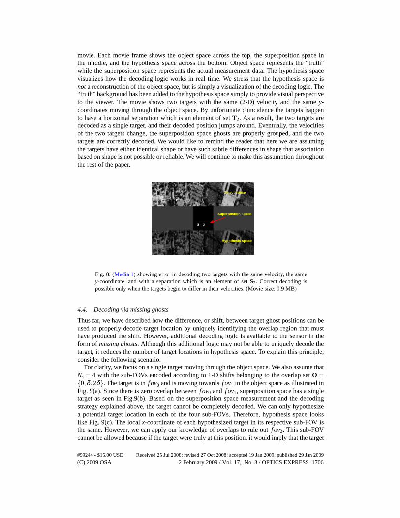
movie. Each movie frame shows the object space across the top, the superposition space inthe middle, and the hypothesis space across the bottom. Object space represents the “truth”while the superposition space represents the actual measurement data. The hypothesis spacevisualizes how the decoding logic works in real time. We stress that the hypothesis space isnota reconstruction of the object space, but is simply a visualization of the decoding logic. The“truth” background has been added to the hypothesis space simply to provide visual perspectiveto the viewer. The movie shows two targets with the same (2-D)velocity and the samey-coordinates moving through the object space. By unfortunate coincidence the targets happento have a horizontal separation which is an element of setT2. As a result, the two targets aredecoded as a single target, and their decoded position jumpsaround. Eventually, the velocitiesof the two targets change, the superposition space ghosts are properly grouped, and the twotargets are correctly decoded. We would like to remind the reader that here we are assumingthe targets have either identical shape or have such subtle differences in shape that associationbased on shape is not possible or reliable. We will continue to make this assumption throughoutthe rest of the paper.
Object space
Superpostion space
Hypothesis space
Fig. 8. (Media 1) showing error in decoding two targets with the same velocity, the samey-coordinate, and with a separation which is an element of setS2. Correct decoding ispossible only when the targets begin to differ in their velocities. (Movie size: 0.9 MB)
4.4. Decoding via missing ghosts
Thus far, we have described how the difference, or shift, between target ghost positions can beused to properly decode target location by uniquely identifying the overlap region that musthave produced the shift. However, additional decoding logic is available to the sensor in theform of missing ghosts. Although this additional logic may not be able to uniquely decode thetarget, it reduces the number of target locations in hypothesis space. To explain this principle,consider the following scenario.
For clarity, we focus on a single target moving through the object space. We also assume thatNs = 4 with the sub-FOVs encoded according to 1-D shifts belonging to the overlap setO ={0,δ ,2δ}. The target is inf ov0 and is moving towardsf ov1 in the object space as illustrated inFig. 9(a). Since there is zero overlap betweenf ov0 and f ov1, superposition space has a singletarget as seen in Fig.9(b). Based on the superposition spacemeasurement and the decodingstrategy explained above, the target cannot be completely decoded. We can only hypothesizea potential target location in each of the four sub-FOVs. Therefore, hypothesis space lookslike Fig. 9(c). The localx-coordinate of each hypothesized target in its respective sub-FOV isthe same. However, we can apply our knowledge of overlaps to rule out f ov2. This sub-FOVcannot be allowed because if the target were truly at this position, it would imply that the target
#99244 - $15.00 USD Received 25 Jul 2008; revised 27 Oct 2008; accepted 19 Jan 2009; published 29 Jan 2009
(C) 2009 OSA 2 February 2009 / Vol. 17, No. 3 / OPTICS EXPRESS 1706

(a)
(b)
(c)
Fig. 9. (a) Encoded Object Space with 4 sub-FOVs. The target is inf ov0. The local f ov0x-coordinate lies betweenWf ov−O2 andWf ov. (b) The superposition Space with a singletarget indicating that the target is in a non-overlapping sub-FOV region. (c) HypothesisSpace with 4 potential targets. The third hypothesized target, however, liesin a sub-FOVoverlap which if true would produce ghosts in the Superposition Space. The absence ofghosts rules out this hypothesized target as a potential true target.
resides in an overlapping region betweenf ov2 and f ov3. The absence of a second ghost insuperposition space tells us this is not true. Therefore, the target can only be inf ov0, f ov1 orf ov3, and we have reduced the target hypotheses from 4 to 3. If the target continues to movetoward f ov2, additional sub-FOVs will be ruled out by the same logic. In general, missingghosts can be used to rule out anywhere from one to all incorrect sub-FOVs depending on thetarget location and encoding structure.
5. Results
To demonstrate and quantify the efficacy of the proposed 1-D spatial shift encoding scheme,we present results generated from both simulated data and a laboratory experiment.
5.1. Simulation
We simulated an object space withNs = 8, 1-D spatial-shift encoded sub-FOVs. The size ofeach sub-FOV was 64∆r distance units by 64∆r distance units, where∆r, the object spaceresolution, was assumed to be finer than the size of the targets of interest. The correspondingsub-FOV dimensionality (in pixels) is 64 by 64. In the simulation we used template matching to
#99244 - $15.00 USD Received 25 Jul 2008; revised 27 Oct 2008; accepted 19 Jan 2009; published 29 Jan 2009
(C) 2009 OSA 2 February 2009 / Vol. 17, No. 3 / OPTICS EXPRESS 1707

Fig. 10. Examples of valid target patterns.
perform correlation for locating target ghost positions. In order to subtract the background clut-ter from the measured data before performing the correlation, we characterized the backgroundby averaging the superposition space data for a large numberof frames under the assumptionthat we have the ability to observe the scene for a long time with respect to the frame rate.
We first defined the overlap set asO = {0,1δ ,2δ ,4δ ,3δ ,5δ ,6δ} where δ was chosenas δ = δmax = f loor(Wf ov/(Ns− 1)) = floor(64/7) = 9 pixels. The reason for this choiceof δ was that largeδ increases the boundary density in the superposition space,which in-creases the total overlapped area. As a result, the number oftarget ghosts in superpositionspace that need to be tracked increases. If the decoder and tracker can handle a large numberof targets in superposition space, we can gain confidence that the decoding procedure is ro-bust. Note that the overlaps in the setO are not monotonically increasing, which shows thatthe order of the overlaps in 1-D shift encoding is arbitrary.Based on this overlap set, theseparation set is computed to beS = {64,55,46,28,37,19,10}. The allowed target patternsare then given byT2 = {64,55,46,28,37,10},T3 = {{37,28},{19,37},{10,19}} andT4 ={{10,19,37}}. The sets of overlapping sub-FOVs corresponding to these patterns areF2 = {{0,1},{1,2},{2,3},{3,4},{4,5},{6,7}},F3 = {{3,4,5},{4,5,6},{5,6,7}} andF4 ={{4,5,6,7}}. It is important to point out that{5,6} is absent from the setF2. This does notimply that the two sub-FOVs do not overlap, which they do, butinstead means that the regionof overlap betweenf ov5 and f ov6 is also overlapped by a third or a even a fourth sub-FOVas shown in the setsF3 andF4 respectively. In Fig. 10 we illustrate the allowed target patternswith a couple of examples.
We simulated a scenario by populating the object space with four identically shaped targetsappearing at random locations, with random velocities, at random times, and lasting for randomdurations. We allowed the starting target locations to be anywhere in the object space withequal probability. The velocities were uniformly distributed between 0 and 3∆r distance unitsfor every time step to ensure that the target movement lookedreal. The start and stop timeswere uniformly distributed between 0 and 100 time steps. Figure 11 shows a movie of one suchexample simulation which best illustrates all the facets ofour decoding procedure. We explainthis movie in the next paragraph. Our algorithm is able to handle many more identically shaped
#99244 - $15.00 USD Received 25 Jul 2008; revised 27 Oct 2008; accepted 19 Jan 2009; published 29 Jan 2009
(C) 2009 OSA 2 February 2009 / Vol. 17, No. 3 / OPTICS EXPRESS 1708

Superposition space
Hypothesis space
Object space
Fig. 11. (Media 2) showing the decoding of 4 targets that appear at random times and forrandom durations at random locations. The movie shows the successful decoding of allthe 4 targets. Each frame shows the encoded object space (δ = δmax), the correspondingmeasured superposition space (with static background subtracted out) and the resultinghypothesis space. (Movie size: 1.25 MB)
targets than the four chosen here, but using only a few targets allows the reader to easily followthe decoding logic shown in the movie.
The movie in Fig. 11 shows four identically shaped color-coded targets in the object space.Color coding allows easy target discrimination for the reader. The first target in the object spaceis the red target which is followed by a white target. Both these targets are decoded via missingghosts logic as they travel through the object space. This can be seen in the hypothesis spacewhere the ambiguity in the locations of these two targets is completely removed even beforethe targets reach a boundary. The green target appears next and is followed by the blue target.Since the blue target appears in a region of overlap off ov1 and f ov2, it is almost immediatelydecoded. The green target is decoded when it reaches the region of overlap betweenf ov1 andf ov2. Thus all four targets are successfully decoded.
The movie shows us that the decoding time of targets differs depending on the target loca-tion and the target velocity. Also, because of possible errors in measurement it is possible thatwe incorrectly decode a target. This is especially true for targets with very low SNR. There-fore, decoding time and measurement errors can affect system performance. We next considertwo metrics useful in quantifying this system performance.One metric considers the effect ofshift resolution on average decoding time and the other considers the probability of incorrectdecoding. We investigate these metrics in the following sub-sections.
5.2. Average decoding time and area coverage efficiency (η)
A small shift resolution (smallα) implies that the degree of overlap between adjacent sub-FOVs is small. One potential disadvantage of small shift resolution is that the average time ittakes to decode a target (decoding time) increases.
The problem can arise as follows: when a new target ghost appears in superposition space,velocity estimates are not instantaneously available. Therefore, it takes some time to determineif the new ghost should be associated with an existing group,or if it is due to a new targetaltogether. To get velocity information we must wait a few time steps while the Kalman trackerupdates the state vector and obtains a stable velocity estimate. This waiting period can presenta problem, especially when the target is in a sub-FOV with a small overlap. If the target has ahigh x-velocity, it is possible that the target may not stay in the overlap region for enough timefor the Kalman tracker to ascertain the target velocity. This results in increased decoding time.
#99244 - $15.00 USD Received 25 Jul 2008; revised 27 Oct 2008; accepted 19 Jan 2009; published 29 Jan 2009
(C) 2009 OSA 2 February 2009 / Vol. 17, No. 3 / OPTICS EXPRESS 1709
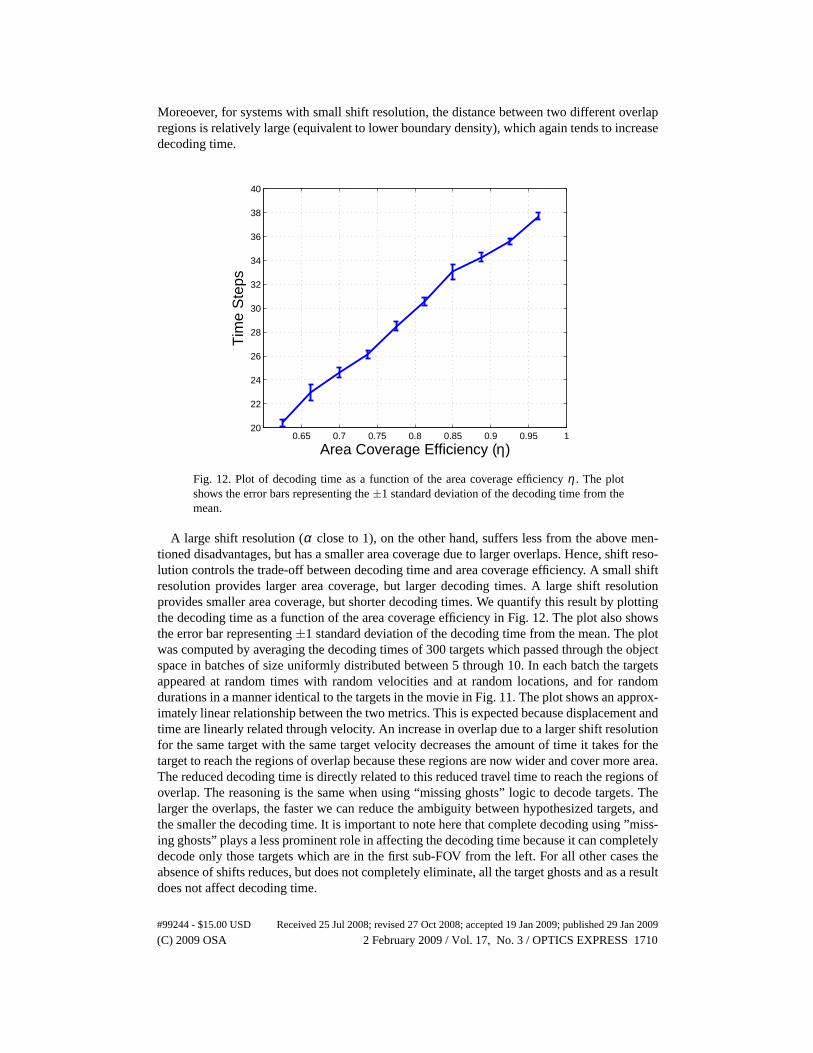
Moreoever, for systems with small shift resolution, the distance between two different overlapregions is relatively large (equivalent to lower boundary density), which again tends to increasedecoding time.
0.65 0.7 0.75 0.8 0.85 0.9 0.95 120
22
24
26
28
30
32
34
36
38
40
Area Coverage Efficiency (η)
Tim
e S
teps
Fig. 12. Plot of decoding time as a function of the area coverage efficiency η . The plotshows the error bars representing the±1 standard deviation of the decoding time from themean.
A large shift resolution (α close to 1), on the other hand, suffers less from the above men-tioned disadvantages, but has a smaller area coverage due tolarger overlaps. Hence, shift reso-lution controls the trade-off between decoding time and area coverage efficiency. A small shiftresolution provides larger area coverage, but larger decoding times. A large shift resolutionprovides smaller area coverage, but shorter decoding times. We quantify this result by plottingthe decoding time as a function of the area coverage efficiency in Fig. 12. The plot also showsthe error bar representing±1 standard deviation of the decoding time from the mean. The plotwas computed by averaging the decoding times of 300 targets which passed through the objectspace in batches of size uniformly distributed between 5 through 10. In each batch the targetsappeared at random times with random velocities and at random locations, and for randomdurations in a manner identical to the targets in the movie inFig. 11. The plot shows an approx-imately linear relationship between the two metrics. This is expected because displacement andtime are linearly related through velocity. An increase in overlap due to a larger shift resolutionfor the same target with the same target velocity decreases the amount of time it takes for thetarget to reach the regions of overlap because these regionsare now wider and cover more area.The reduced decoding time is directly related to this reduced travel time to reach the regions ofoverlap. The reasoning is the same when using “missing ghosts” logic to decode targets. Thelarger the overlaps, the faster we can reduce the ambiguity between hypothesized targets, andthe smaller the decoding time. It is important to note here that complete decoding using ”miss-ing ghosts” plays a less prominent role in affecting the decoding time because it can completelydecode only those targets which are in the first sub-FOV from the left. For all other cases theabsence of shifts reduces, but does not completely eliminate, all the target ghosts and as a resultdoes not affect decoding time.
#99244 - $15.00 USD Received 25 Jul 2008; revised 27 Oct 2008; accepted 19 Jan 2009; published 29 Jan 2009
(C) 2009 OSA 2 February 2009 / Vol. 17, No. 3 / OPTICS EXPRESS 1710
5.3. Probability of decoding error
We next consider the probability of decoding error, which isdefined as the probability that thetarget pattern decoded from superposition space measurements is an incorrect pattern. In thepresence of noise and other distortion, the estimated position of a target ghost in superpositionspace will be subject to error. Therefore, the difference between two ghost positions, which isthe criterion for target decoding in a shift-encoded system, will also be subject to error. Theseerrors can lead to the wrong pattern being detected, which will cause the target to be decodedto the wrong location. Furthermore, as the shift resolutionδ is decreased, more fidelity inestimating target shifts is required.
Figure 13 shows the results from a simplified calculation of decoding error for a single targetpresent in a region of overlap betweenM sub-FOVs. We first consider overlaps between twosub-FOVs and then extend the result to overlaps between three and four sub-FOVs. We assume,as we did for the simulation example in sub-section 5.1, thatthe imaging system superimposes8 sub-FOVs onto a single FPA. The width of each sub-FOV is 500∆r distance units, where∆ris the object space resolution. We assume that the error in estimating the position of a ghostin superposition space is Gaussian distributed with variance determined by the Cramer-RaoBound (CRB) [24] applicable to this problem. The CRB is
var[x] ≥ 1SNR·Brms
, (6)
where SNR is proportional to the target intensity andBrms is the root-mean-square (rms) band-width of the target’s intensity profile in the encoded dimension. For example, we have useda symmetric triangular intensity pattern, which has a closed-form rms bandwidth of 12/W2
t[pixels−2] whereWt is the target width in pixels.
We first consider the case of a single target present in a region overlapped by two sub-FOVs(M = 2). The target pattern for this case consists of a single distance between two ghosts. Ifthe position errors on the two ghosts are independent, then the variance of the distance estimateis twice the variance in (6). We assume that the target is decoded only if the measured overlapmatches an allowed overlap from the overlap setO to within some prescribed toleranceε. (Notethat the distance between the two ghosts is related to the overlap throughSi = Wf ov−Oi , i =0,1, . . . ,Ns−2. See section 4 for more details.) If the measured overlap isnot withinε of a validoverlap then the target remains undecoded. For example, if the true shift ismδ , a decoding erroris made only if the measured overlapd satisfies(m+ k)δ − ε ≤ d ≤ (m+ k)δ + ε wherek isa non-zero integer and(m+k)δ is a valid overlap. The probability of decoding error can nowbe computed by integrating the Gaussian error probability distribution over the error region.This error probability is conditioned onmδ being the true overlap. Therefore, to calculate thetotal probability of decoding error we have to know thea priori probability of the true overlapbeingmδ . We assume that this probability is uniformly distributed.The value ofε, in general,is dependent on the structure of the overlap setO. We, however, have chosen the overlaps tobe multiples of the shift resolutionδ . As a result all the overlap values are equally spaced fromthe adjacent ones. We can therefore letε be some fixed tolerance value less than or equal toδ/2, whereδ , the shift resolution, is the separation between two successive overlaps. Whenε = δ/2 we always make a decoding decision. Ifε < δ/2, there are cases where the measuredoverlap does not lie within the tolerance limit of any element of O and we let the target remainundecoded. In contrast, if the overlap set contains random but unique overlaps, the toleranceε is a function ofO. For instance, theε tolerance value for overlaps with a large spacingbetween them will be different from theε tolerance value for the overlaps that are closelyspaced, especially for the case where we always make a decoding decision. The tolerance value,therefore, will have to be adjusted according to the overlaps.
#99244 - $15.00 USD Received 25 Jul 2008; revised 27 Oct 2008; accepted 19 Jan 2009; published 29 Jan 2009
(C) 2009 OSA 2 February 2009 / Vol. 17, No. 3 / OPTICS EXPRESS 1711

0.6 0.65 0.7 0.75 0.8 0.85 0.9 0.95 110
−10
10−8
10−6
10−4
10−2
100
Area Coverage Efficiency (η)
Pro
babi
lity
of D
ecod
ing
Err
or
SNR = 0 dB, M = 2SNR = 0 dB, M = 3SNR = 0 dB, M = 4SNR = 5 dB, M = 2SNR = 5 dB, M = 3SNR = 5 dB, M = 4SNR = 10 dB, M = 2SNR = 10 dB, M = 3SNR = 10 dB, M = 4
Fig. 13. Plot of decoding error versus area coverage efficiency for different SNRs anddifferent values ofM, the number of sub-FOVs that overlap.
We can extend the above result to the general case whereM sub-FOVs overlap. In our ex-ample we can have a maximum ofM = 4. For the case ofM = 3, instead of measuring asingle overlapd, we measure two overlapsd1 and d2 resulting from the pair-wise distancesbetween three target ghosts in the superposition space. Therefore, we now have a 2-D Gaus-sian error probability distribution. The probability of decoding error is calculated by integrat-ing this 2-D distribution over the region given by(m1 + k1)δ − ε ≤ d1 ≤ (m1 + k1)δ + ε and(m2 +k2)δ − ε ≤ d2 ≤ (m2 +k2)δ + ε. Herem1δ andm2δ are the true overlaps, andk1 andk2
are non-zero shifts such that(m1 + k1)δ and(m2 + k2)δ are valid overlaps. We again assumethat the probability of the true overlaps beingm1δ andm2δ is uniformly distributed. Extentionto M = 4, where we have a 3-D Gaussian error probability distribution is straightforward.
Figure 13 shows the probability of decoding error versus area coverage efficiency forε =δ/2,Wt = 10∆r distance units, and different values of SNR andM. As the shift resolutiondecreases, area coverage efficiency increases, but so does probability of decoding error. Thus,the choice of shift resolution is a compromise between the area coverage and the probabilityof incorrectly decoding the target location. We also observe that for fixed SNR, as we increaseM the decoding error decreases. We therefore conclude that longer target patterns make thedecoding process more robust and less prone to decoding errors.
5.4. Experimental results
To illustrate how 1-D spatial shift encoding of multiple sub-FOVs can be performed in real-world applications we conducted an experiment using the optical setup proposed in Fig. 3(b).The object space used for the experiment was an aerial map of the Duke University campus, anda laser pointer was moved across it during the video aquisition to simulate a single moving tar-get. The object space was 24-mm high and 162-mm wide, and was imaged using the multiplexerin Fig. 3(b) onto a commercial video camera (SONY, DCR-SR42). By adjusting the tilts of themirrors shown in Fig. 3(b), we obtained an overlap setO = {3,7,11,20,14,24,28}× 1mmwhich deviated slightly from the ideal scenario of{0,5,10,20,15,25,30}×1mm. In building
#99244 - $15.00 USD Received 25 Jul 2008; revised 27 Oct 2008; accepted 19 Jan 2009; published 29 Jan 2009
(C) 2009 OSA 2 February 2009 / Vol. 17, No. 3 / OPTICS EXPRESS 1712

the setup, care was taken to make the path lengths travelled by light from each sub-FOV closeto equal. However, there was a slight difference in path lengths which resulted in varying mag-nification of some sub-FOVs. Therefore, the size of each sub-FOV was not uniform:W f ov ={35,34,33,35,33,32,33,34}×1mm andH f ov = {24,23,22,23,22,22,22,23}×1mm, wherethe ith elements ofW f ov andH f ov are the width and height off ovi , respectively.
Fig. 14. Experimental data movie showing successful decoding a target moving throughthe object space. Intial target ambiguity is reduced using “missing ghosts” logic and iscompletely removed as the target enters the region of overlap. (Media 3) (Movie size: 3.9MB)
Figure 14 is a movie we made using this experimental setup. The movie shows the measuredsuperposition space along with the corresponding hypothesis space. Using the decoding logicdiscussed in Section 4 we are able to decode the moving targetas it enters the region of overlap.The movie also shows how the “missing ghosts” logic reduces ambiguity about the target’s truelocation in the hypothesis space. The small deviations of the overlaps from their true values donot affect the performance because all the overlaps are still unique. Uniqueness of overlaps isboth the necessary and sufficient condition for the applicability of our decoding strategy. Also,the slight variations in magnification of the sub-FOVs do notaffect the decoding performance.
6. Conclusion
In this paper we proposed a novel technique to track targets without conventional image re-constructions. The method is based on optical multiplexingof encoded sub-FOVs to createsuperposition space data that can be used to decode target positions in object space. We pro-posed a class of low complexity multiplexed imagers to perform optical encoding and showedthat they are light, cheap and have a simple design in comparison to the conventional imagers.We discussed different encoding schemes based on spatial shifts, rotations, and magnificationwith special emphasis on 1-D spatial shift encoding. We showed, based on both simulation andexperimental data, that the proposed method does indeed localize targets in object space andprovides continuous target tracking capability. We have also studied the trade-offs between areacoverage efficiency, compression ratio, and decoding time,and decoding error as a function ofshift resolution and SNR.
#99244 - $15.00 USD Received 25 Jul 2008; revised 27 Oct 2008; accepted 19 Jan 2009; published 29 Jan 2009
(C) 2009 OSA 2 February 2009 / Vol. 17, No. 3 / OPTICS EXPRESS 1713
Copyright © 2022 FDOKUMEN