Design Code Example Superposition acc. to BS EN 1990
20
Design Code Example SOFiSTiK AG 2010 Design Code Example Superposition acc. to BS EN 1990
-
Upload
khangminh22 -
Category
Documents
-
view
0 -
download
0
Transcript of Design Code Example Superposition acc. to BS EN 1990

Design Code Example
SOFiSTiK AG 2010
Design Code Example
Superposition acc. to
BS EN 1990
Design Code Example
page 1 Superposition BS EN 1990 (12.2009)
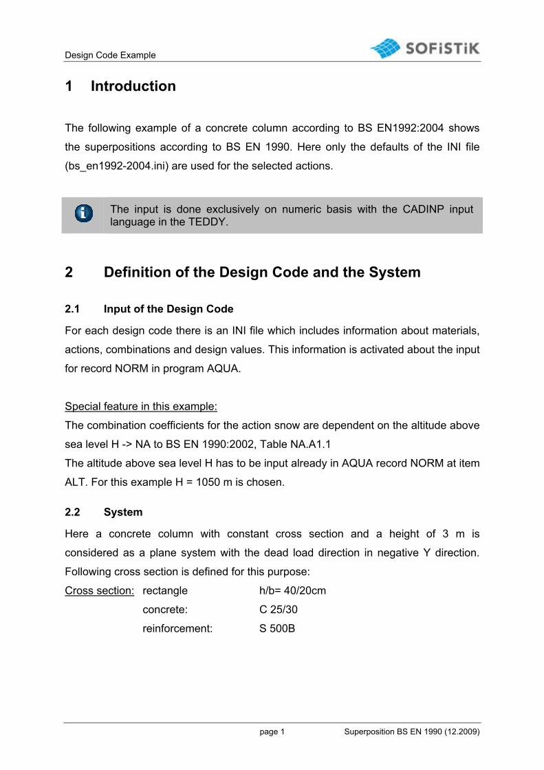
1 Introduction
The following example of a concrete column according to BS EN1992:2004 shows
the superpositions according to BS EN 1990. Here only the defaults of the INI file
(bs_en1992-2004.ini) are used for the selected actions.
The input is done exclusively on numeric basis with the CADINP input language in the TEDDY.
2 Definition of the Design Code and the System
2.1 Input of the Design Code
For each design code there is an INI file which includes information about materials,
actions, combinations and design values. This information is activated about the input
for record NORM in program AQUA.
Special feature in this example:
The combination coefficients for the action snow are dependent on the altitude above
sea level H -> NA to BS EN 1990:2002, Table NA.A1.1
The altitude above sea level H has to be input already in AQUA record NORM at item
ALT. For this example H = 1050 m is chosen.
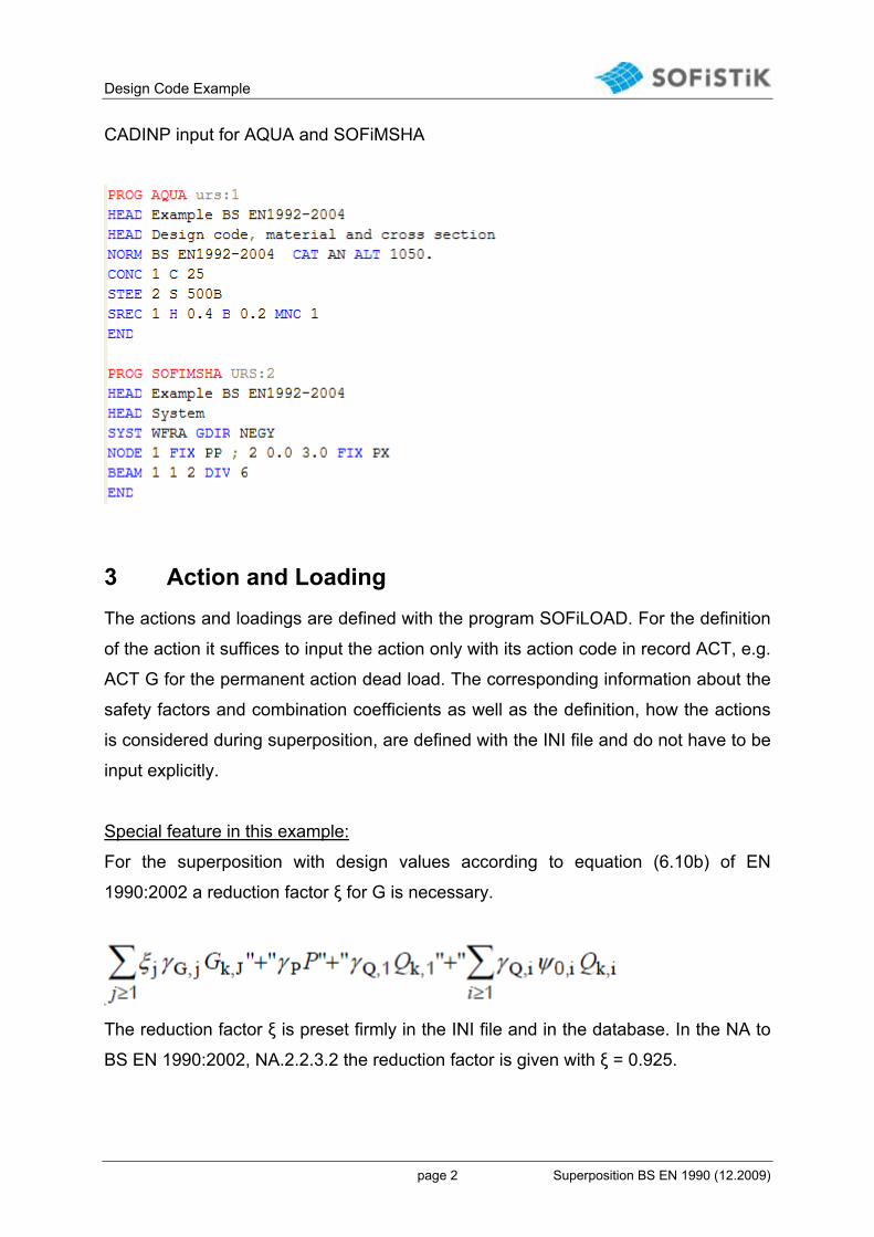
2.2 System
Here a concrete column with constant cross section and a height of 3 m is
considered as a plane system with the dead load direction in negative Y direction.
Following cross section is defined for this purpose:
Cross section: rectangle h/b= 40/20cm
concrete: C 25/30
reinforcement: S 500B
Design Code Example
page 2 Superposition BS EN 1990 (12.2009)
CADINP input for AQUA and SOFiMSHA
3 Action and Loading
The actions and loadings are defined with the program SOFiLOAD. For the definition
of the action it suffices to input the action only with its action code in record ACT, e.g.
ACT G for the permanent action dead load. The corresponding information about the
safety factors and combination coefficients as well as the definition, how the actions
is considered during superposition, are defined with the INI file and do not have to be
input explicitly.
Special feature in this example:
For the superposition with design values according to equation (6.10b) of EN
1990:2002 a reduction factor ξ for G is necessary.
The reduction factor ξ is preset firmly in the INI file and in the database. In the NA to
BS EN 1990:2002, NA.2.2.3.2 the reduction factor is given with ξ = 0.925.
Design Code Example
page 3 Superposition BS EN 1990 (12.2009)
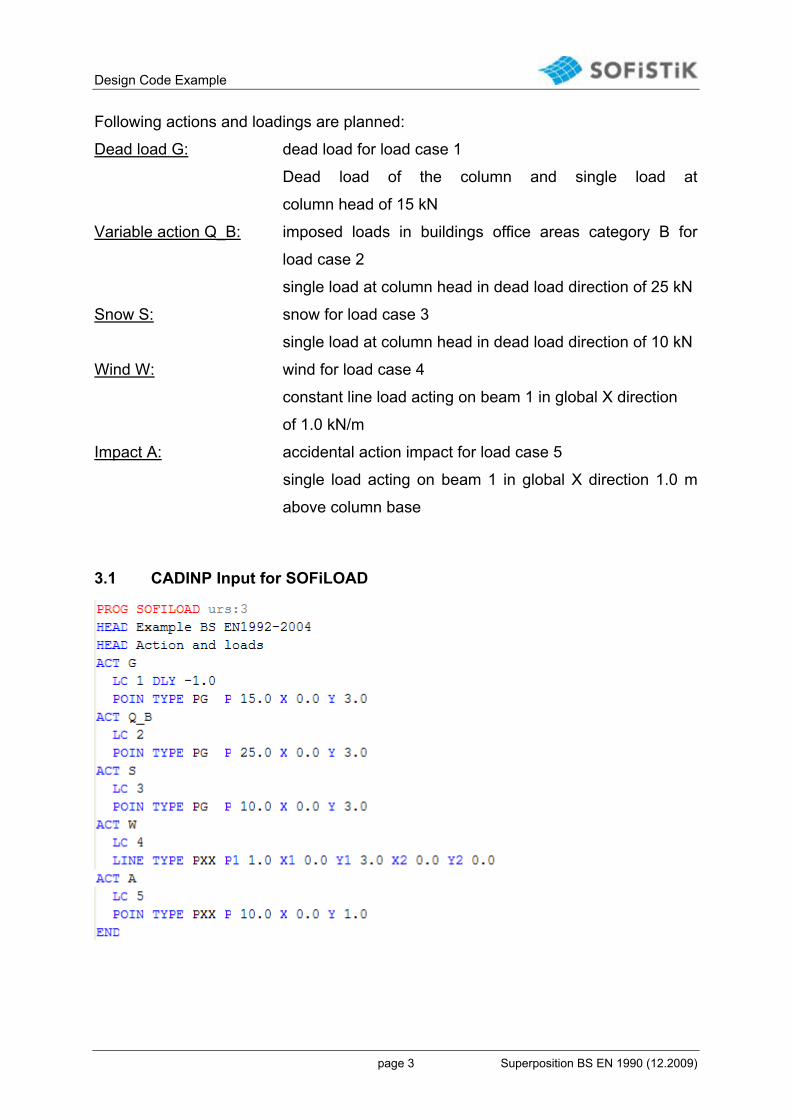
Following actions and loadings are planned:
Dead load G: dead load for load case 1
Dead load of the column and single load at
column head of 15 kN
Variable action Q_B: imposed loads in buildings office areas category B for
load case 2
single load at column head in dead load direction of 25 kN
Snow S: snow for load case 3
single load at column head in dead load direction of 10 kN
Wind W: wind for load case 4
constant line load acting on beam 1 in global X direction
of 1.0 kN/m
Impact A: accidental action impact for load case 5
single load acting on beam 1 in global X direction 1.0 m
above column base
3.1 CADINP Input for SOFiLOAD
Design Code Example
page 4 Superposition BS EN 1990 (12.2009)
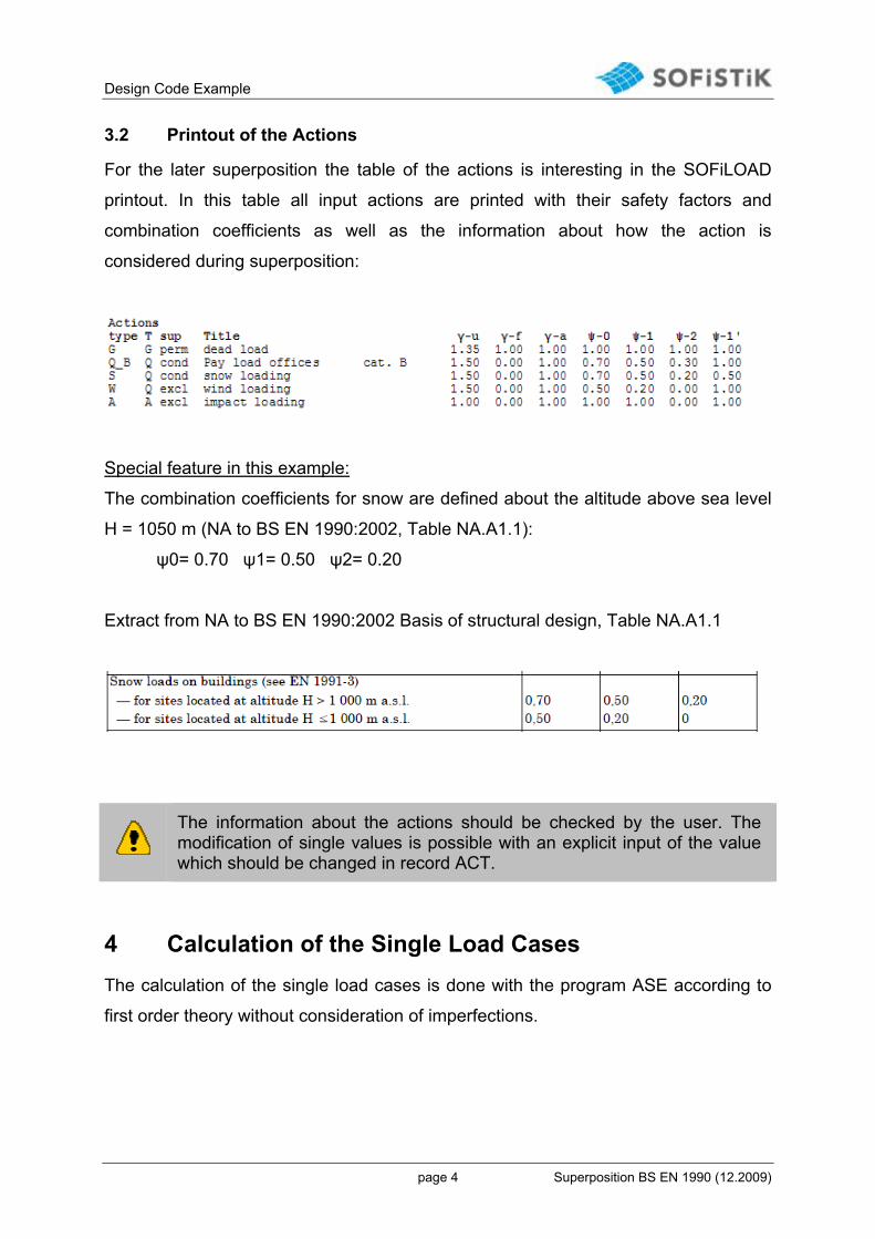
3.2 Printout of the Actions
For the later superposition the table of the actions is interesting in the SOFiLOAD
printout. In this table all input actions are printed with their safety factors and
combination coefficients as well as the information about how the action is
considered during superposition:
Special feature in this example:
The combination coefficients for snow are defined about the altitude above sea level
H = 1050 m (NA to BS EN 1990:2002, Table NA.A1.1):
ψ0= 0.70 ψ1= 0.50 ψ2= 0.20
Extract from NA to BS EN 1990:2002 Basis of structural design, Table NA.A1.1
The information about the actions should be checked by the user. The modification of single values is possible with an explicit input of the value which should be changed in record ACT.
4 Calculation of the Single Load Cases
The calculation of the single load cases is done with the program ASE according to
first order theory without consideration of imperfections.

Design Code Example
page 5 Superposition BS EN 1990 (12.2009)
5 Combinations and Superpositions
5.1 Defaults
The combinations with the corresponding superpositions are preset in the INI file.
These defaults are shown in the Superposition Manager (SSD tasks ‘Define
Combinations‘ and ’Superpositioning’) and can be modified there. With the following
MAXIMA input in TEDDY it is possible to calculate the defaults from the INI file. The
input of the records CTRL and ECHO is not urgently necessary here.
5.1.1 CADINP Input
5.1.2 Printout
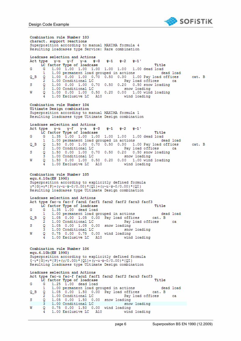
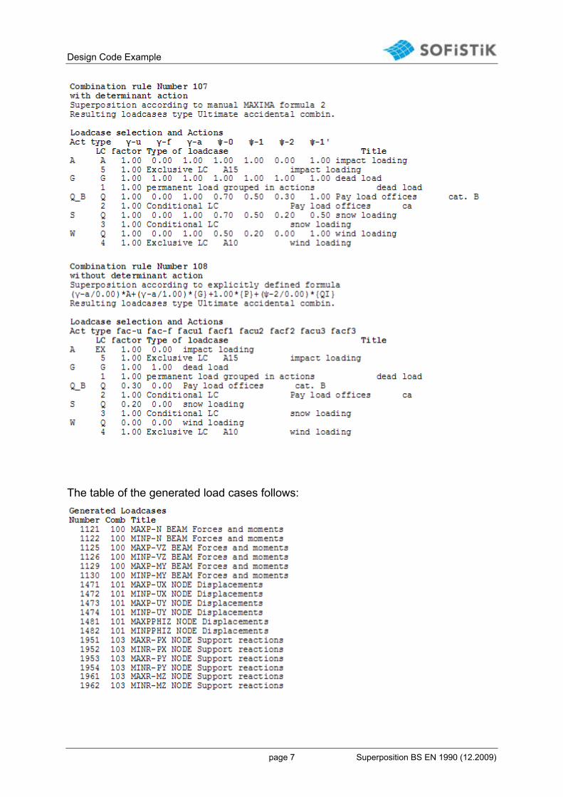
At first the single combinations are printed with their corresponding check list of the
actions and load cases:
Design Code Example
page 6 Superposition BS EN 1990 (12.2009)
Design Code Example
page 7 Superposition BS EN 1990 (12.2009)
The table of the generated load cases follows:

Design Code Example
page 8 Superposition BS EN 1990 (12.2009)
Design Code Example
page 9 Superposition BS EN 1990 (12.2009)
The printout of the relevant values of the single superposition is requested with the
input ECHO CHCK. All factors which are necessary for the superposition as well as
the initial values of the single load cases are printed in the tables. A further
description of the output is done in chapter 5.2.2.
The user should check the superposition by investigating random samples! For this the printout of the relevant values with ECHO CHCK is recommended.
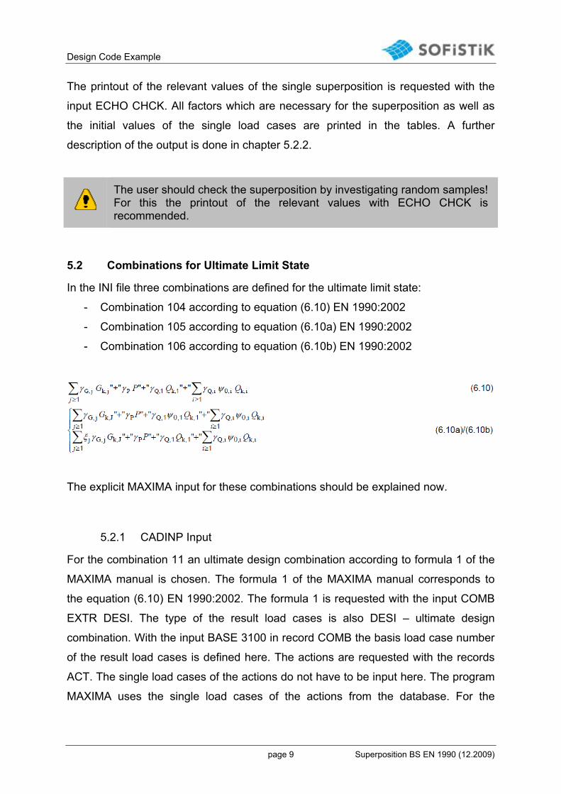
5.2 Combinations for Ultimate Limit State
In the INI file three combinations are defined for the ultimate limit state:
- Combination 104 according to equation (6.10) EN 1990:2002
- Combination 105 according to equation (6.10a) EN 1990:2002
- Combination 106 according to equation (6.10b) EN 1990:2002
The explicit MAXIMA input for these combinations should be explained now.
5.2.1 CADINP Input
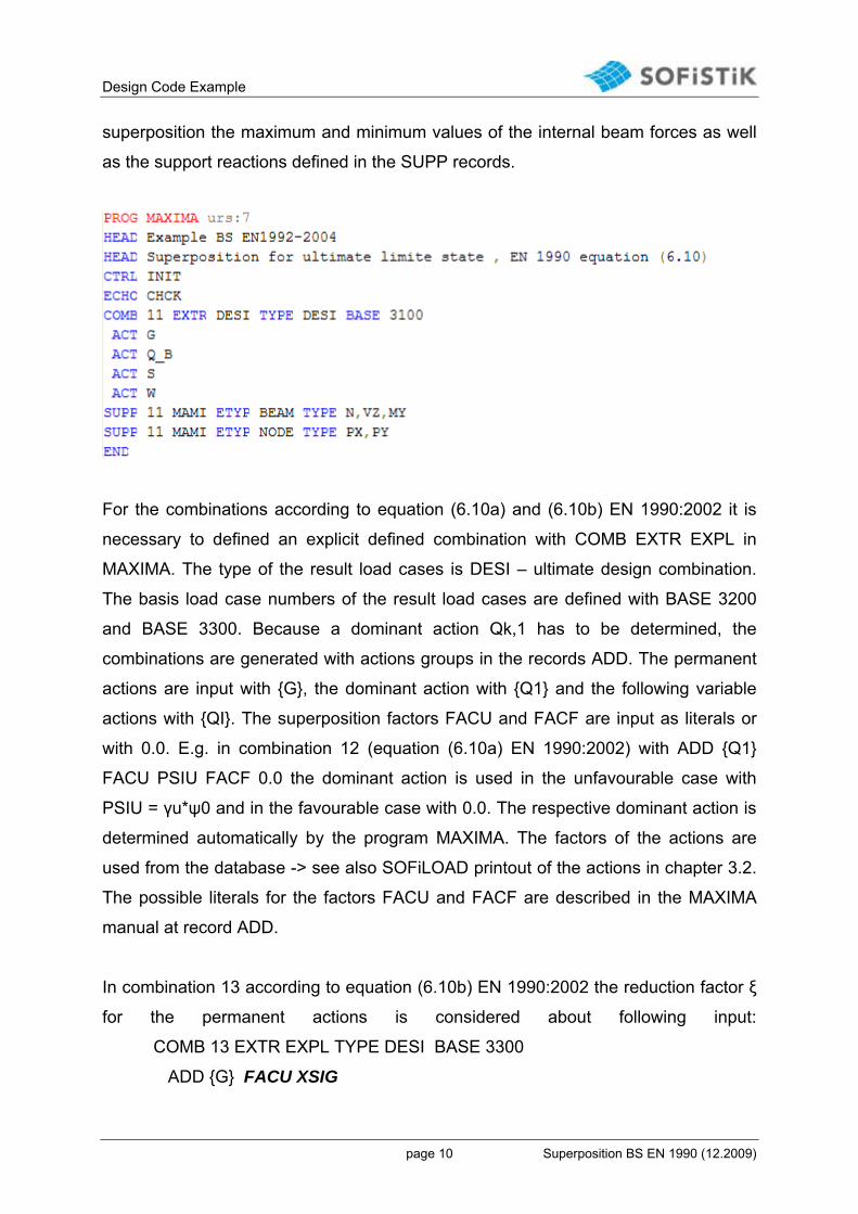
For the combination 11 an ultimate design combination according to formula 1 of the
MAXIMA manual is chosen. The formula 1 of the MAXIMA manual corresponds to
the equation (6.10) EN 1990:2002. The formula 1 is requested with the input COMB
EXTR DESI. The type of the result load cases is also DESI – ultimate design
combination. With the input BASE 3100 in record COMB the basis load case number
of the result load cases is defined here. The actions are requested with the records
ACT. The single load cases of the actions do not have to be input here. The program
MAXIMA uses the single load cases of the actions from the database. For the
Design Code Example
page 10 Superposition BS EN 1990 (12.2009)
superposition the maximum and minimum values of the internal beam forces as well
as the support reactions defined in the SUPP records.
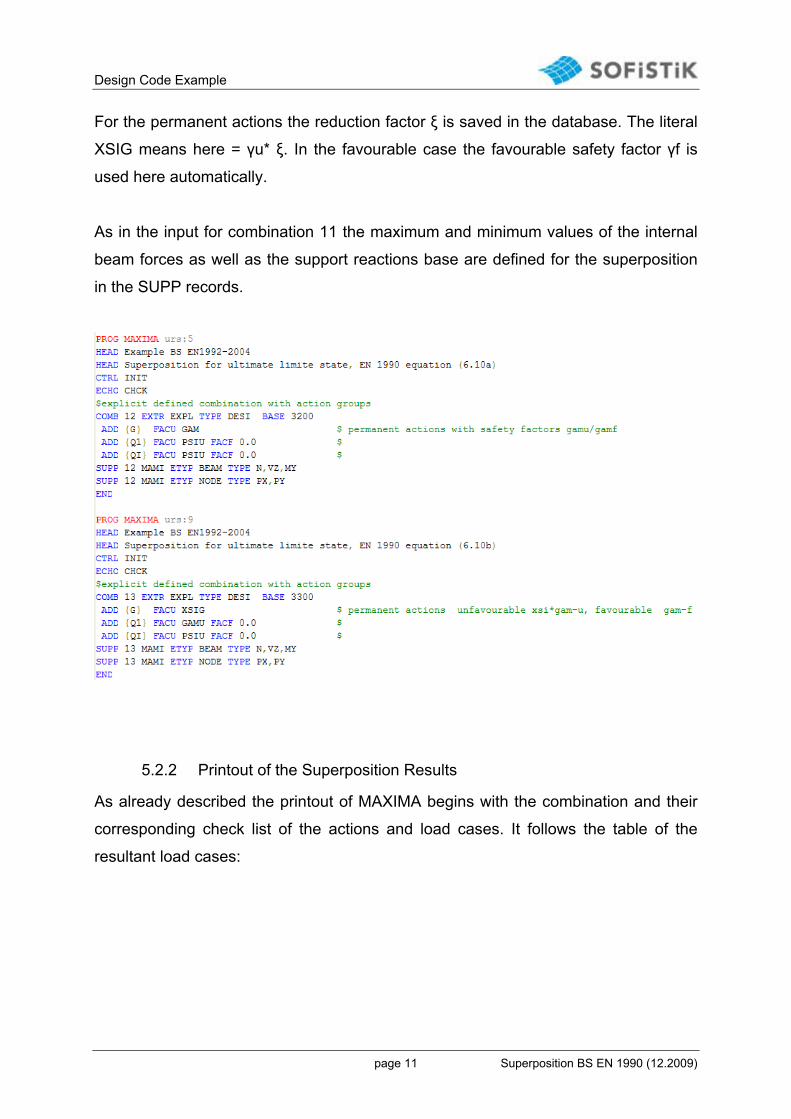
For the combinations according to equation (6.10a) and (6.10b) EN 1990:2002 it is
necessary to defined an explicit defined combination with COMB EXTR EXPL in
MAXIMA. The type of the result load cases is DESI – ultimate design combination.
The basis load case numbers of the result load cases are defined with BASE 3200
and BASE 3300. Because a dominant action Qk,1 has to be determined, the
combinations are generated with actions groups in the records ADD. The permanent
actions are input with {G}, the dominant action with {Q1} and the following variable
actions with {QI}. The superposition factors FACU and FACF are input as literals or
with 0.0. E.g. in combination 12 (equation (6.10a) EN 1990:2002) with ADD {Q1}
FACU PSIU FACF 0.0 the dominant action is used in the unfavourable case with
PSIU = γu*ψ0 and in the favourable case with 0.0. The respective dominant action is
determined automatically by the program MAXIMA. The factors of the actions are
used from the database -> see also SOFiLOAD printout of the actions in chapter 3.2.
The possible literals for the factors FACU and FACF are described in the MAXIMA
manual at record ADD.
In combination 13 according to equation (6.10b) EN 1990:2002 the reduction factor ξ
for the permanent actions is considered about following input:
COMB 13 EXTR EXPL TYPE DESI BASE 3300
ADD {G} FACU XSIG
Design Code Example
page 11 Superposition BS EN 1990 (12.2009)
For the permanent actions the reduction factor ξ is saved in the database. The literal
XSIG means here = γu* ξ. In the favourable case the favourable safety factor γf is
used here automatically.
As in the input for combination 11 the maximum and minimum values of the internal
beam forces as well as the support reactions base are defined for the superposition
in the SUPP records.
5.2.2 Printout of the Superposition Results
As already described the printout of MAXIMA begins with the combination and their
corresponding check list of the actions and load cases. It follows the table of the
resultant load cases:

Design Code Example
page 12 Superposition BS EN 1990 (12.2009)
- for combination 11
- for combination 12
Design Code Example
page 13 Superposition BS EN 1990 (12.2009)
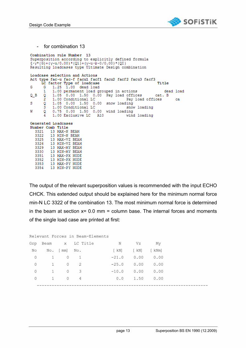
- for combination 13
The output of the relevant superposition values is recommended with the input ECHO
CHCK. This extended output should be explained here for the minimum normal force
min-N LC 3322 of the combination 13. The most minimum normal force is determined
in the beam at section x= 0.0 mm = column base. The internal forces and moments
of the single load case are printed at first:
Relevant Forces in Beam-Elements
Grp Beam x LC Title N Vz My
No No. [mm] No. [kN] [kN] [kNm]
0 1 0 1 -21.0 0.00 0.00
0 1 0 2 -25.0 0.00 0.00
0 1 0 3 -10.0 0.00 0.00
0 1 0 4 0.0 1.50 0.00
---------------------------------------------------------------------
Design Code Example
page 14 Superposition BS EN 1990 (12.2009)
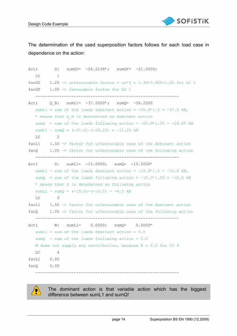
The determination of the used superposition factors follows for each load case in
dependence on the action:
Acti G: sumGU= -26.2238*; sumGF= -21.0000;
LC 1
facGU 1.25 -> unfavourable factor = γu*ξ = 1.35*0.925=1.25 for LC 1
facGF 1.00 -> favourable factor for LC 1
------------------------------------------------------------
Acti Q_B: sumL1= -37.5000*; sumQ= -26.2500
sumL1 = sum of the loads dominant action = -25.0*1.5 = -37.5 kN,
* means that Q_B is determined as dominant action
sumQ = sum of the loads following action = -25.0*1.05 = -26.25 kN
sumL1 – sumQ = (-37.5)-(-26.25) = -11.25 kN
LC 2
facL1 1.50 -> factor for unfavourable case of the dominant action
facQ 1.05 -> factor for unfavourable case of the following action
------------------------------------------------------------
Acti S: sumL1= -15.0000; sumQ= -10.5000*
sumL1 = sum of the loads dominant action = -10.0*1.5 = -15.0 kN,
sumQ = sum of the loads following action = -10.0*1.05 = -10.5 kN
* means that S is determined as following action
sumL1 – sumQ = (-15.0)-(-10.5) = -4.5 kN
LC 3
facL1 1.50 -> factor for unfavourable case of the dominant action
facQ 1.05 -> factor for unfavourable case of the following action
------------------------------------------------------------
Acti W: sumL1= 0.0000; sumQ= 0.0000*
sumL1 = sum of the loads dominant action = 0.0
sumQ = sum of the loads following action = 0.0
W does not supply any contribution, because N = 0.0 for LC 4
LC 4
facL1 0.00
facQ 0.00
------------------------------------------------------------
The dominant action is that variable action which has the biggest difference between sumL1 and sumQ!

Design Code Example
page 15 Superposition BS EN 1990 (12.2009)
The determined factor and the superimposed minimum normal force for the beam at
x=0.0 are printed in three lines at the end:
LC 1 2 3 4
fact 1.25 1.50 1.05 0.00
---------------------------------------------------------------------
0 1 0 3322 MIN-N BE -74.2 0.00 0.00
Min-N = 1.25*(-21.0) + 1.5*(-25.0) + 1.05*(-10.0) = -74.2 kN
The designation MAX or MIN at the superposition refers exclusively to the sign of the superposition values: positive sign -> MAX negative sign -> MIN
5.3 Accidental Combinations
In the INI file there are preset two accidental combinations:
- Combination 106 according to equation (6.11b) EN 1990:2002 using ψ1*Qk,1
-> with dominant action
- Combination 107 according to equation (6.11b) EN 1990:2002 using ψ2*Qk,1
-> without dominant action
The explicit MAXIMA input for these combinations should be explained now.
Design Code Example
page 16 Superposition BS EN 1990 (12.2009)
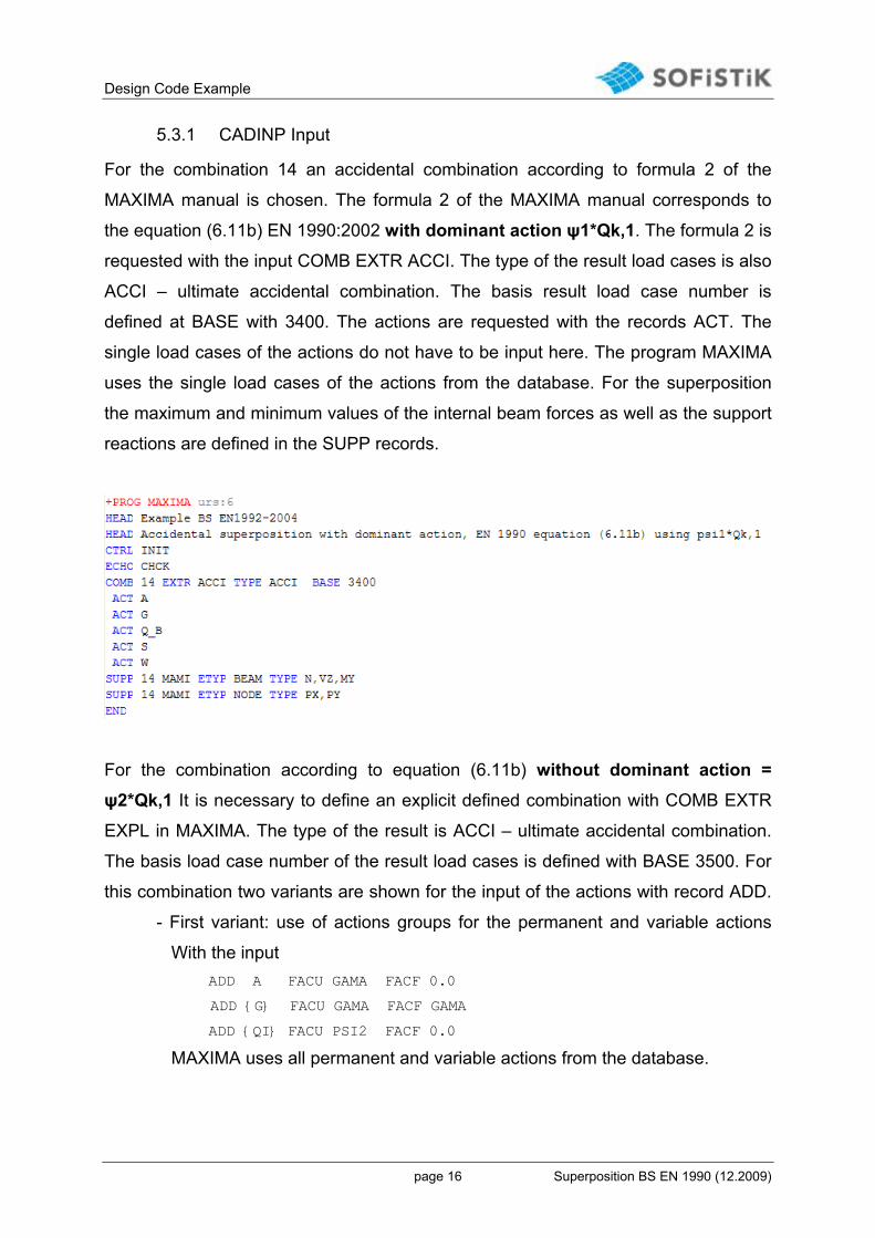
5.3.1 CADINP Input
For the combination 14 an accidental combination according to formula 2 of the
MAXIMA manual is chosen. The formula 2 of the MAXIMA manual corresponds to
the equation (6.11b) EN 1990:2002 with dominant action ψ1*Qk,1. The formula 2 is
requested with the input COMB EXTR ACCI. The type of the result load cases is also
ACCI – ultimate accidental combination. The basis result load case number is
defined at BASE with 3400. The actions are requested with the records ACT. The
single load cases of the actions do not have to be input here. The program MAXIMA
uses the single load cases of the actions from the database. For the superposition
the maximum and minimum values of the internal beam forces as well as the support
reactions are defined in the SUPP records.
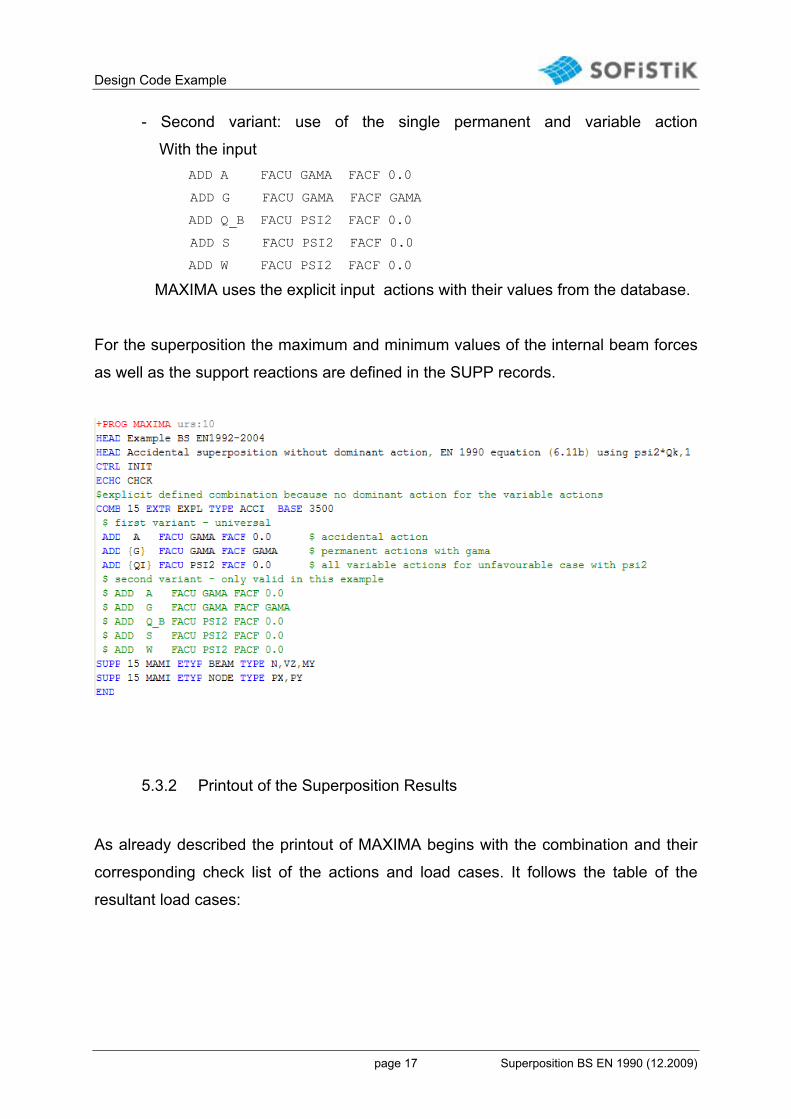
For the combination according to equation (6.11b) without dominant action =
ψ2*Qk,1 It is necessary to define an explicit defined combination with COMB EXTR
EXPL in MAXIMA. The type of the result is ACCI – ultimate accidental combination.
The basis load case number of the result load cases is defined with BASE 3500. For
this combination two variants are shown for the input of the actions with record ADD.
- First variant: use of actions groups for the permanent and variable actions
With the input
ADD A FACU GAMA FACF 0.0
ADD {G} FACU GAMA FACF GAMA
ADD {QI} FACU PSI2 FACF 0.0
MAXIMA uses all permanent and variable actions from the database.
Design Code Example
page 17 Superposition BS EN 1990 (12.2009)
- Second variant: use of the single permanent and variable action
With the input
ADD A FACU GAMA FACF 0.0
ADD G FACU GAMA FACF GAMA
ADD Q_B FACU PSI2 FACF 0.0
ADD S FACU PSI2 FACF 0.0
ADD W FACU PSI2 FACF 0.0
MAXIMA uses the explicit input actions with their values from the database.
For the superposition the maximum and minimum values of the internal beam forces
as well as the support reactions are defined in the SUPP records.
5.3.2 Printout of the Superposition Results
As already described the printout of MAXIMA begins with the combination and their
corresponding check list of the actions and load cases. It follows the table of the
resultant load cases:
Design Code Example
page 18 Superposition BS EN 1990 (12.2009)
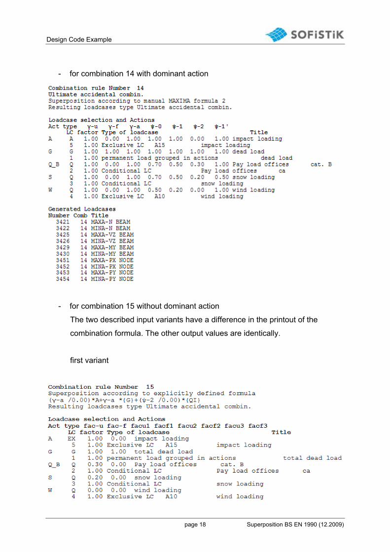
- for combination 14 with dominant action
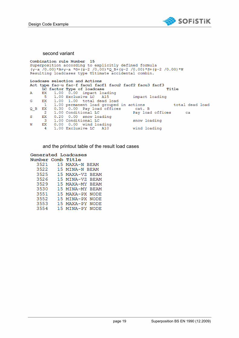
- for combination 15 without dominant action
The two described input variants have a difference in the printout of the
combination formula. The other output values are identically.
first variant
Design Code Example
page 19 Superposition BS EN 1990 (12.2009)
second variant
and the printout table of the result load cases