BS/A Manual | Proxxon
11
BS/A Manual
-
Upload
khangminh22 -
Category
Documents
-
view
2 -
download
0
Transcript of BS/A Manual | Proxxon
BS/A
Manual
- 3 -
4343 FöhrenBS
2
23
1
2
1
1
2
1
2
21
1
2
3
2
4
1
345768
9
10
11
12
1 2
Fig. 2
Fig. 3
Fig. 1
Fig. 4Fig. 5
Fig. 6
Fig. 7
Fig. 8

- 10 -
Original operating instructions PROXXON - BS/A
Dear customer!
Always keep these operating instructions and the enclosed safety guidelines within reach.Only use this device with exact knowledge of it and comply with the instructions and safety guidelines!
This is necessary to ensure safe operation and, secondly, it facilitates familiarisation with the de-vice and its functions.
Proxxon assumes no liability for the safe function of the device in the case of:
• handling that does not comply with normal intended use,• use for other purposes not mentioned in the manual,• incorrectly executed repairs,• failure to heed safety instructions,• external effects for which the manufacturer is not responsible.
We recommend using PROXXON original spare parts for all repair and maintenance work.Repairs should only be performed by qualifi ed skilled personnel!
Please note: All information contained in these ope-rating instructions - especially the technical data - corresponds to the status at the time of printing.
We reserve the right to make further develop-ments in the interest of technical progress. We wish you every success with the device.
Warning! Read through all safety guidelines and instruc-tions! Failure to adhere to
safety guidelines and instructions can result in electrical shock, fi re and/or serious injuries as consequence.
Store all safety guidelines and instructions for the future.
WarningAlways wear protective goggles
Only for use in dry rooms
Charger LG/AProtection class II device
Do not dispose of the power tool, charger or battery with household rubbish!
Wear hearing protection!
Description of the machineThe PROXXON BS/A belt sander is a light, compact and handy device ideal for model, tool and mould construction but which can also be used for the repair of motor vehicles.
Application examples are • grinding in of grooves• correcting of especially inaccessible areas• re-sanding of especially complexly formed shapes• grinding out of small openings and break- throughs, regardless of the materials, and also high-strength steels• straightening, smooth sanding and high-shine polishing of surfaces: the pulled grinding does not leave annoying grinding marks• grinding of saw blades, chisels and even cutting tools• precision polishing of surfaces• removal of paints and varnishes• rounding off of edges• deburring and chamfering of precision parts, etc.
The high-grade corundum sanding belts enable machining of metal, plastic and wood.An extremely robust gearbox transfers the moti-ve force to the driving roller for the sanding belt at the gear head. This runs on the grinding head where it is diver-ted by a tightening roller at the front end. The grinding head can be swivelled to enable work even at inaccessible areas.
GB
- 11 -
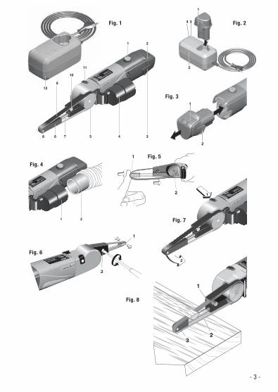
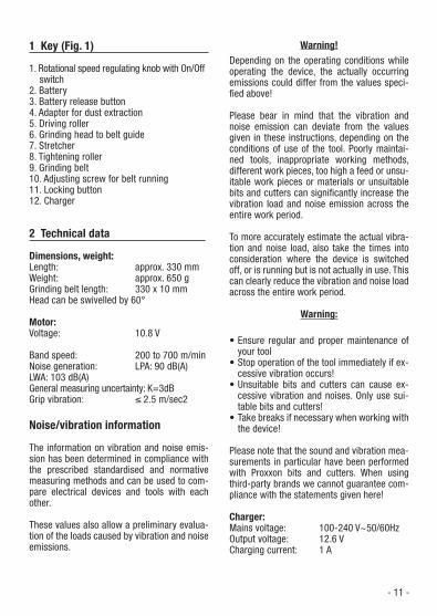
1 Key (Fig. 1)
1. Rotational speed regulating knob with On/Off switch
2. Battery3. Battery release button4. Adapter for dust extraction5. Driving roller6. Grinding head to belt guide7. Stretcher8. Tightening roller9. Grinding belt10. Adjusting screw for belt running11. Locking button12. Charger
2 Technical data
Dimensions, weight:Length: approx. 330 mm Weight: approx. 650 g Grinding belt length: 330 x 10 mm Head can be swivelled by 60°
Motor:Voltage: 10.8 V
Band speed: 200 to 700 m/min Noise generation: LPA: 90 dB(A) LWA: 103 dB(A)General measuring uncertainty: K=3dBGrip vibration: ≤ 2.5 m/sec2
Noise/vibration information
The information on vibration and noise emis-sion has been determined in compliance with the prescribed standardised and normative measuring methods and can be used to com-pare electrical devices and tools with each other.
These values also allow a preliminary evalua-tion of the loads caused by vibration and noise emissions.
Warning!Depending on the operating conditions while operating the device, the actually occurring emissions could differ from the values speci-fi ed above!
Please bear in mind that the vibration and noise emission can deviate from the values given in these instructions, depending on the conditions of use of the tool. Poorly maintai-ned tools, inappropriate working methods, different work pieces, too high a feed or unsu-itable work pieces or materials or unsuitable bits and cutters can signifi cantly increase the vibration load and noise emission across the entire work period.
To more accurately estimate the actual vibra-tion and noise load, also take the times into consideration where the device is switched off, or is running but is not actually in use. This can clearly reduce the vibration and noise load across the entire work period.
Warning:
• Ensure regular and proper maintenance of your tool
• Stop operation of the tool immediately if ex-cessive vibration occurs!
• Unsuitable bits and cutters can cause ex-cessive vibration and noises. Only use sui-table bits and cutters!
• Take breaks if necessary when working with the device!
Please note that the sound and vibration mea-surements in particular have been performed with Proxxon bits and cutters. When using third-party brands we cannot guarantee com-pliance with the statements given here!
Charger:Mains voltage: 100-240 V~50/60HzOutput voltage: 12.6 VCharging current: 1 A

- 12 -
Battery:Rechargeable lithium-ion batteryNominal/charging voltage: 10.8V/12.6V Energy/Capacity: 28.19Wh/2.61Ah 3 INR 19/66
3 Scope of delivery
BS/A (29810)1 pc. Belt sander BS/A1 pc. Connection adapter1 pc. Rubber connecting piece1 pc. Storage case1 pc. Charger 1 pc. Battery1 pc. Operating instructions 1 pc. Safety guidelines2 pcs. Fan sander K 802 pcs. Fan sander K 180
BS/A (29812)1 pc. Belt sander BS/A1 pc. Connection adapter1 pc. Rubber connecting piece1 pc. Operating instructions 1 pc. Safety guidelines2 pcs. Fan sander K 802 pcs. Fan sander K 180
4 Commissioning and operation
Caution: Before starting up, read the warning instruc-tions and the labels attached to the charger and the battery!
Use and handling of battery-powered tool
a. Batteries should only be charged with the chargers recommended by the ma-nufacturer. A charger suitable for a certain type of battery poses a fi re hazard if used with other batteries.
b. Use only the designated batteries in the power tools. The use of other batteries can
cause injuries and pose a fi re hazard.c. Keep unused batteries away from paper
clips, coins, keys, nails, screws and other small metal objects which could bridge the contacts. A short-circuit between the battery contacts can cause burns or fi re.
d. If used incorrectly, the battery can leak fl uids. Avoid contact. In the event of in-cidental contact, rinse with water. If the fl uid gets into your eyes, seek medical assistance. Leaking battery fl uids can cause skin irritations or burns.
e. Do not use a damaged or modifi ed bat-tery. Damaged or modifi ed batteries can behave unpredictably and cause fi res, ex-plosions or injuries.
f. Never expose a battery to fi re or exces-sive temperatures. Fire or temperatures above 130°C can cause an explosion.
g. Observe all charging instructions and never charge the battery or battery-pow-ered tool outside the temperature range specifi ed by the operating instructions. Incorrect charging or charging outside the approved temperature range can destroy the battery and increase the risk of fi re.
Service
a. Have your power tool repaired only by qualifi ed specialists and use only origi-nal spare parts. This ensures that the pow-er tool remains safe to operate.
b. Never service damaged batteries. All maintenance work on batteries should only be carried out by the manufacturer or autho-rised customer service centres.
Charging the battery (Fig. 2 and 3)
Please note: The device, battery and charge are also separately available at retailers!
When delivered, the battery is partially char-ged and must be charged completely before commissioning the device. To do so, proceed as follows:
- 13 -
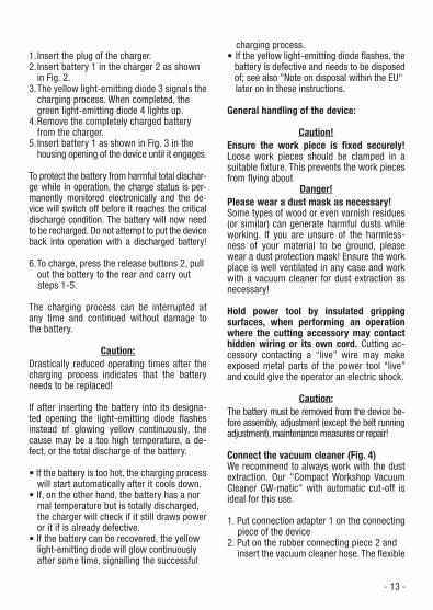
1. Insert the plug of the charger.2. Insert battery 1 in the charger 2 as shown
in Fig. 2.3. The yellow light-emitting diode 3 signals the charging process. When completed, the
green light-emitting diode 4 lights up.4. Remove the completely charged battery from the charger.5. Insert battery 1 as shown in Fig. 3 in the housing opening of the device until it engages.
To protect the battery from harmful total dischar-ge while in operation, the charge status is per-manently monitored electronically and the de-vice will switch off before it reaches the critical discharge condition. The battery will now need to be recharged. Do not attempt to put the device back into operation with a discharged battery!
6. To charge, press the release buttons 2, pull out the battery to the rear and carry out
steps 1-5.
The charging process can be interrupted at any time and continued without damage to the battery.
Caution:Drastically reduced operating times after the charging process indicates that the battery needs to be replaced!
If after inserting the battery into its designa-ted opening the light-emitting diode fl ashes instead of glowing yellow continuously, the cause may be a too high temperature, a de-fect, or the total discharge of the battery.
• If the battery is too hot, the charging process will start automatically after it cools down. • If, on the other hand, the battery has a nor mal temperature but is totally discharged,
the charger will check if it still draws power or it if is already defective. • If the battery can be recovered, the yellow light-emitting diode will glow continuously after some time, signalling the successful
charging process. • If the yellow light-emitting diode fl ashes, the battery is defective and needs to be disposed of; see also "Note on disposal within the EU"
later on in these instructions.
General handling of the device:
Caution!Ensure the work piece is fi xed securely! Loose work pieces should be clamped in a suitable fi xture. This prevents the work pieces from fl ying about
Danger!Please wear a dust mask as necessary!Some types of wood or even varnish residues (or similar) can generate harmful dusts while working. If you are unsure of the harmless-ness of your material to be ground, please wear a dust protection mask! Ensure the work place is well ventilated in any case and work with a vacuum cleaner for dust extraction as necessary!
Hold power tool by insulated gripping surfaces, when performing an operation where the cutting accessory may contact hidden wiring or its own cord. Cutting ac-cessory contacting a “live” wire may make exposed metal parts of the power tool “live” and could give the operator an electric shock.
Caution:The battery must be removed from the device be-fore assembly, adjustment (except the belt running adjustment), maintenance measures or repair!
Connect the vacuum cleaner (Fig. 4)We recommend to always work with the dust extraction. Our "Compact Workshop Vacuum Cleaner CW-matic" with automatic cut-off is ideal for this use.
1. Put connection adapter 1 on the connecting piece of the device2. Put on the rubber connecting piece 2 and insert the vacuum cleaner hose. The fl exible
- 14 -
rubber material makes it possible to use different diameters.
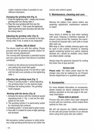
Changing the grinding belt (Fig. 5)1. Press the tightening roller 1 axially and remove grinding belt from driving roller 2.2. Place the new grinding belt fi rst over the tightening roller 1. Then press the tightening roller towards the back and place the belt over the driving roller 2.
Adjusting the grinding roller (Fig. 6)The grinding belt must run centrally on the tigh-tening roller. If not, it needs to be readjusted.
Caution, risk of injury!The device must run with this setting. Please proceed with the greatest possible caution for the belt running adjustment!The running belt represents a potential hazard and can cause injuries if the device is handled carelessly!
1. Switch on the device by turning the button 1 and setting the small belt speed.2. Turn the adjusting screw 2 to the left or right until the belt runs centrally on the tightening roller 1.
Adjusting the grinding head (Fig. 7)1. Press in locking button 1 whilst adjusting the grinding head 2 to the desired angle.2. Release the locking button. The grinding head engages.
Working with the device (Fig. 8)1. Activate the device with the rotational speed regulating knob (1, Fig. 1) and set the right speed for the work.2. The grinding surface 2 is particularly suited for machining fl at surfaces. 3. Grinding surface 1 is best used to grind curves. 4. Face side 3 is suited for work on tight openings
and recesses.
Note:Not excessive contact pressure is what achie-ves a high grinding performance but rather the
correct and uniform speed.
5 Maintenance, cleaning and care
Caution:Remove the battery from device before any assembly, adjustment, maintenance measure or repair!
Note:Every device is dirtied by dust when working with wood. Cleaning is therefore essential. To ensure a long service life, however, the machi-ne should be cleaned with a soft cloth or brush after each use.Mild soap or other suitable cleaning agent may be used in this context. Solvents or cleaning agents containing alcohol (e.g. petrol, cleaning alcohols etc.) should be avoided, since these can attack plastic casings.
Always keep the apertures required for cooling the motor free of dust and dirt.
Service note Please note: The mains power input for the charger may only be replaced by our Proxxon Service Department or a qualifi ed specialist!
6 Accessories
For more detailed information on accessories, please request our device catalogue from the address specifi ed on the last page in the war-ranty information.
Please note in general:Proxxon bits and cutters have been designed to work with our machines, which makes them optimal for their use.
We will not assume any liability whatsoever for the safe and proper function of our devices when using third-party bits and cutters!

- 15 -
8 CE Declaration of conformity
Name and address of the manufacturer: PROXXON S.A.6-10, HärebiergL-6868 Wecker
Product designation: BS/AArticle No.: 29810/29812
On our sole responsibility, we declare that this product conforms to the following directives and normative documents:
EU EMC Directive 2016/30/EUDIN EN 55014-1/09.2016DIN EN 55014-2/01.2016DIN EN 61000-3-2/03.2015DIN EN 61000-3-3/03.2014DIN EN 61000-4-2/12.2009DIN EN 61000-4-3/04.2011DIN EN 61000-4-4/04.2013DIN EN 61000-4-5/03.2015DIN EN 61000-4-6/08.2014DIN EN 61000-4-11/02.2005
EU Machinery Directive 2006/42/ECDIN EN 62841-1/07.2016DIN EN 62841-2-4/05.2015
Date: 15.02.2017 Dipl.-Ing. Jörg Wagner
PROXXON S.A.Appliance Safety Division
The CE document authorized agent is identical with the signatory.
7 Disposal:
Please do not dispose of this machine in household waste! The device contains valu-able materials which can be recycled. If you have questions concerning this topic, please contact your municipal disposal company or other appropriate municipal institutions.
Note on disposal within the EU:Please note that in accordance with the EU directive 2012/19/EU and the EU directive 2006/66/EC, defective or consumed accu-mulators and no longer operational electrical devices must be disposed of separately from household waste and must be sent for reuse in an environmentally responsible manner!
- 81 -
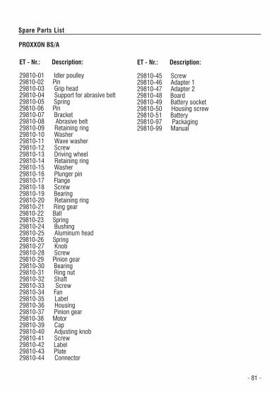
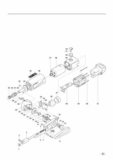
Spare Parts List
PROXXON BS/A
ET - Nr.: Description: ET - Nr.: Description:
- 83 -
D-54343 FöhrenBS/E
220 V~
50/60 Hz
100 Watt
n max= 13.00/m
inNr.:
5800-0203
1
2
3
56
4 78
91011
12
1314
15
16
1718
1920
2122
2324
25
2627
28
29 30 31 32
33 34
35 36
37 38 39
4344
45
46
47
48 49 50 51
40
4241

Service note All PROXXON products are thoroughly inspected after production. Should a defect occur nevertheless, pleasecontact the dealer from whom you purchased the pro-duct. Only the dealer is responsible for handling alllegal warranty claims which refer exclusively to materialand manufacturer error.Improper use, such as capacity overload, damage due tooutside infl uences and normal wear are excluded from the warranty.You will fi nd further notes regarding „Service and Spare Parts Management“ at www.proxxon.com.
GB