XM678D Controllers for Multiplexed Cabinets with Interior ...
72
XM678D Controllers for Multiplexed Cabinets with Interior Stepper Driver Installation and Operation Manual 026-1224 Rev 1
-
Upload
khangminh22 -
Category
Documents
-
view
4 -
download
0
Transcript of XM678D Controllers for Multiplexed Cabinets with Interior ...

XM678D Controllers for Multiplexed Cabinets with Interior Stepper Driver Installation and Operation Manual
026-1224 Rev 1


Emerson Digital Cold Chain, Inc.1065 Big Shanty Road NW, Suite 100
Kennesaw, GA 30144 USA770-425-2724 • 1-800-829-2724
www.climate.emerson.comEmail: [email protected]


Contents • v
Contents1 INTRODUCTION.......................................................................................................................................................... 1
1.1. GENERAL WARNING ..................................................................................................................................................... 1
2 BEFORE PROCEEDING ............................................................................................................................................. 2
2.1. SOFTWARE RELEASE OF XM678D............................................................................................................................... 2
3 GENERAL DESCRIPTION ......................................................................................................................................... 3
3.1. ORDERING CODES......................................................................................................................................................... 3
4 INSTALLATION AND MOUNTING ......................................................................................................................... 4
5 WIRING DIAGRAM AND CONNECTIONS ............................................................................................................ 5
5.1. IMPORTANT NOTE......................................................................................................................................................... 55.3. XM678D ...................................................................................................................................................................... 55.4. VALVES CONNECTIONS AND CONFIGURATION............................................................................................................. 6
5.4.1. Valve Connections................................................................................................................................................ 65.4.2. Type of Cables and Max Length ........................................................................................................................... 65.4.3. Valve Selection...................................................................................................................................................... 6
5.5. ABSOLUTE MAXIMUM POWER..................................................................................................................................... 75.6. KEYBOARD DISPLAY CX660 ....................................................................................................................................... 85.7. LAN CONNECTION ....................................................................................................................................................... 85.8. SENSORS FOR SUPERHEAT CONTROL ........................................................................................................................... 95.9. HOW TO USE A SINGLE PRESSURE TRANSDUCER ON MULTIPLEXED APPLICATIONS .................................................. 95.10. HOW TO CONNECT THE MONITORING SYSTEM.......................................................................................................... 105.11. DIGITAL INPUTS.......................................................................................................................................................... 115.12. ANALOG OUTPUT ....................................................................................................................................................... 12
6 QUICK REFERENCE GUIDE IN RUNNING THE SELF ADAPTIVE REGULATION .................................. 13
7 BATTERY BACK UP CONNECTION..................................................................................................................... 14
7.1. CONNECTION OF XEC SUPERCAP............................................................................................................................... 147.2. EMERSON ECP-024 CONNECTION.............................................................................................................................. 15
8 USER INTERFACE .................................................................................................................................................... 16
8.1. ICONS.......................................................................................................................................................................... 168.2. KEYBOARD COMMANDS............................................................................................................................................. 16
8.2.1. Double Commands ............................................................................................................................................. 178.3. HOW TO MODIFY THE AIR TEMPERATURE REGULATION SETPOINT .......................................................................... 17
9 HOW TO PROGRAM THE PARAMETERS (PR1 AND PR2) ............................................................................. 18
9.1. HOW TO ENTER PR2 ................................................................................................................................................... 189.2. HOW TO MOVE A PARAMETER FROM PR1 TO PR2 LEVEL AND VICE VERSA............................................................ 18
10 FAST ACCESS MENU ............................................................................................................................................. 19
11 MULTIMASTER FUNCTION MENU (SEC) ........................................................................................................ 20
11.1. SYNCHRONIZED DEFROST....................................................................................................................................... 2111.1.1. Daily Defrost From RTC: [EdF = rtC] ......................................................................................................... 21
12 COMMISSIONING ................................................................................................................................................... 22
12.1. CLOCK SETTING AND RTC ALARM RESET ............................................................................................................ 2212.2. ELECTRONIC VALVE SETTINGS .............................................................................................................................. 22

vi • XM678D I&O Manual 026-1224 Rev 1
13 REGULATION FOR SUPERHEAT: SELF ADAPTIVE OR MANUAL OPERATING MODE..................... 23
13.1. GENERAL CONSIDERATIONS: SELF ADAPTIVE OR MANUAL SH CONTROL............................................................ 2313.2. MANUAL OPERATING MODE - AMS = NO ............................................................................................................ 23
13.2.1. ON/OFF Temperature Regulation [CrE = n]................................................................................................ 2313.2.2. Continuous Temperature Regulation [CrE = Y] (With Superheat Regulation) ............................................ 23
13.3. SELF ADAPTIVE OPERATING MODE - AMS = YES............................................................................................... 2313.4. MINIMUM STABLE SUPERHEAT SEARCH - AMS = YES, ATU = YES.................................................................. 2413.5. VALVE CAPACITY REDUCING - MNF PARAMETER ................................................................................................ 2413.6. PRESSURE FILTERING- ANP PARAMETER .............................................................................................................. 24
14 DISPLAY MESSAGES.............................................................................................................................................. 25
14.1. ALARM RECOVERY ................................................................................................................................................. 26
15 ELECTRONIC EXPANSION VALVE MENU (FOR XM678D ONLY) ............................................................. 27
16 CONTROLLING LOADS......................................................................................................................................... 28
16.1. TEMPERATURE PROBE REFERENCE FOR REGULATION ........................................................................................... 2816.1.1. Sensor Failure ................................................................................................................................................. 28
16.2. DUAL TEMP MODE OPERATION.............................................................................................................................. 2816.2.1. Second Map Function by Digital Input Configuration ................................................................................... 28
16.3. THE SOLENOID VALVE ........................................................................................................................................... 2816.4. STANDARD REGULATION AND CONTINUOUS REGULATION ................................................................................... 28
16.4.1. First Kind of Regulation: ................................................................................................................................ 2916.4.2. Second Kind of Regulation – Continuous Regulation:.................................................................................... 29
16.5. PUMP DOWN BEFORE DEFROST.............................................................................................................................. 2916.6. DEFROST ................................................................................................................................................................. 29
16.6.1. Defrost Starting .............................................................................................................................................. 2916.6.2. Minimum Defrost Time.................................................................................................................................... 2916.6.3. Defrost Ending ................................................................................................................................................. 2916.6.4. Kind of Defrost ................................................................................................................................................ 30
16.7. ON DEMAND DEFROST ........................................................................................................................................... 3016.7.1. Description ...................................................................................................................................................... 3016.7.2. Parameters and Settings.................................................................................................................................. 3016.7.3. Exceptions ....................................................................................................................................................... 30
16.8. FANS ....................................................................................................................................................................... 3016.8.1. Control with Relay ......................................................................................................................................... 3016.8.2. Control With Analog Output (If Present) ....................................................................................................... 31
16.9. ANTI-SWEAT HEATERS........................................................................................................................................... 3116.10. CLEANING MODE FUNCTION BY DIGITAL INPUT CONFIGURATION...................................................................... 32
16.10.1. Display .......................................................................................................................................................... 3216.11. AUXILIARY OUTPUT ............................................................................................................................................. 32
17 PARAMETER LIST.................................................................................................................................................. 33
18 DIGITAL INPUTS..................................................................................................................................................... 46
18.1. GENERIC ALARM (EAL)......................................................................................................................................... 4618.2. SERIOUS ALARM MODE (BAL) .............................................................................................................................. 4618.3. PRESSURE SWITCH (PAL)....................................................................................................................................... 4618.4. DOOR SWITCH INPUT (DOR) ................................................................................................................................... 4618.5. START DEFROST (DEF) .......................................................................................................................................... 4618.6. RELAY AUX ACTUATION (AUS) ............................................................................................................................ 4618.7. RELAY LIGHT ACTUATION (LIG) ........................................................................................................................... 4618.8. REMOTE ON/OFF (ONF) ....................................................................................................................................... 4618.9. FHU – NOT USED................................................................................................................................................... 46

Contents • vii
18.10. ENERGY SAVING INPUT (ES)................................................................................................................................ 4718.11. CLEANING FUNCTION ACTIVATION (CLN) .......................................................................................................... 4718.12. DEFROST END (DEN)........................................................................................................................................... 4718.13. DIGITAL INPUTS POLARITY .................................................................................................................................. 47
19 USE OF THE PROGRAMMING HOT KEY......................................................................................................... 48
19.1. DOWNLOAD (FROM THE HOTKEY TO THE DEVICE) ............................................................................................... 4819.2. UPLOAD (FROM THE DEVICE TO THE HOTKEY) ..................................................................................................... 48
20 TECHNICAL DATA ................................................................................................................................................. 49
21 DEFAULT SETTING VALUES............................................................................................................................... 50
22 ECT MODBUS NETWORKING TO E2S .............................................................................................................. 56
22.1. COM PORT ASSOCIATIONS - E2 VERSIONS 4.0 AND ABOVE................................................................................... 5622.2. E2 SETUP OF DEVICES.............................................................................................................................................. 57
22.2.1. Set Up Network Ports....................................................................................................................................... 5722.2.2. Add and Connect the Device ............................................................................................................................ 57
22.3. WIRING TYPES.......................................................................................................................................................... 5822.4. MODBUS TERMINATION BLOCKS........................................................................................................................... 59


General Warnings Introduction • 1
1 Introduction
1.1. General WarningsPlease read the following safety precautions and warnings before using this manual:
WARNING! An isolated transformer for the XM678D power supply must be used. Do not share power with any other devices.
CAUTION!
• This manual is part of the product and should be kept near the device for easy and quick reference.• The device should not be used for purposes different from those described in this manual. It cannot be used
as a safety device. • Check the application limits before proceeding.
• Emerson reserves the right to change the composition of its products, even without notice, ensuring the same and unchanged functionality.
SAFETY PRECAUTIONS!
• Check that the supply voltage is correct before connecting the device.
• Do not expose to water or moisture: use the controller only within the operating limits and avoid sudden temperature changes with high atmospheric humidity to prevent condensation from forming.
• Warning: Disconnect all electrical connections before performing any kind of maintenance.
• Fit the probe where it is not accessible by the end user. The device must not be opened.
• In case of failure or faulty operation, send the device back to the distributor or to Emerson Retail Solutions (see address) with a detailed description of the fault.
• Verify the maximum current that can be applied to each relay (see Section 20, Technical Data).
• Ensure that the wires for probes, loads, and the power supply are separated and far enough from each other without crossing or intertwining.
• In case of applications in industrial environments, the use of main filters in parallel with inductive loads could be useful.

2 • XM678D I&O Manual 026-1224 Rev 1
2 Before Proceeding
2.1. Software Release of XM678D1. Look at the software release of XM678D printed on the label of the controller.
2. If the software release is 5.4, proceed with this manual; otherwise contact Emerson to access the correct manual.
3. Note that RTC is not supported on devices connected to E2, E3, and Site Supervisor.
Figure 2-1 - Software Release of XM678D 5.4

Ordering Codes General Description • 3
3 General DescriptionThe XM678D are high level microprocessor based controllers for multiplexed cabinets suitable for applications on medium or low temperature. They can be inserted in a LAN of up to eight (8) different sections which can operate, depending on the programming, as stand alone controllers or following the commands coming from the other sections. The XM678D are provided with four (4) and six (6) relay outputs respectively to control the solenoid valve, defrost that can be either electrical or hot gas, evaporator fans, the lights, an auxiliary output (XM678D) and an alarm output (XM678D) and with one output to drive stepper electronic expansion valves. The devices are also provided with four probe inputs, one for temperature control, one to control the defrost end temperature of the evaporator, the third for the display and the fourth can be used for application with virtual probe or for inlet/outlet air temperature measurement. In addition they are provided by other two probes that have to be used for superheat measurement and regulation. Finally, they are equipped with the three digital inputs (free contact) fully configurable by parameters. The Hotkey connector allows simple programming of the controller. The optional direct serial output RS485 that is MODBUS-RTU compatible permits simple XWEB interfacing. Depending on the model, the Hotkey connector can be used to connect the X-REP display.
3.1. Ordering Codes
Part Number Description318-6601 XM678D Case Controller Stepper Control,24V, V5.4, GND, CPC+4.20, with Connectors318-6750 Remote Display Keyboard for XMs
Table 3-1 - Product Ordering Codes

4 • XM678D I&O Manual 026-1224 Rev 1
4 Installation and MountingThis device can operate without any user interface, but normal application is with CX660 or CH660 keyboard (both 660 displays are supported).
The CX660 keyboard should be mounted on a vertical panel, in a 29 x 71 mm hole, and secured using the special bracket supplied Figure 4-1The temperature range allowed for correct operation is 32 to 140°F (0 to 60°C). Avoid places subject to strong vibrations, corrosive gases, excessive dirt or humidity. The same recommendations apply to probes. Allow air to circulate through the cooling holes.
CX660 CH660
Figure 4-1 - CX660 Keyboard Installation and Mounting
Figure 4-2 - CX660 and CH660 Dimensions

Important Note Wiring Diagram and Connections • 5
5 Wiring Diagram and Connections
5.1. Important NoteThe XM device is provided with a disconnectable terminal block to connect cables with a cross-section of up to 1.6 mm2 for all low voltage connections: RS485, LAN, probes, digital inputs, and keyboard. Other inputs, power supply and relay connections are provided with a screw terminal block or Faston connection (5.0 mm). Heat-resistant cables have to be used. Before connecting the cables, verify that the power supply complies with the controller’s requirements. Separate the probe cables from the power supply cables, outputs and power connections. Do not exceed the maximum current allowed on each relay. In case of heavier loads, use a suitable external relay. N.B Maximum current allowed for all loads is 16A.The probes should be mounted with the bulb upwards to prevent damages due to casual liquid infiltration. It is recommended to place the thermostat probe away from air streams to measure the average room temperature correctly. Place the defrost termination probe among the evaporator fans in the coldest place (where most ice is formed) and far from heaters or from the warmest place during defrost to prevent premature defrost termination.
5.2. XM678D
5.3. Valves Connections and Configuration
5.3.1. Valve ConnectionsAll the connections between XM678D and valve has to be done with the controller NOT supplied.
5.3.2. Type of Cables and Max LengthTo connect the valve to the controller, use only shielded cables with section greater than or equal to 0.823 mm² (AWG18). A twisted shielded cable with the above specification is suggested. Do not connect the shield to any ground, live it floating. The max distance between an XM controller and a valve must not exceed 10 meters.
Figure 5-1 - Wiring and Connections

6 • XM678D I&O Manual 026-1224 Rev 1
5.3.3. Valve SelectionTo avoid possible problems, before connecting the valve configure the driver by making the right changes on the parameters.
a. Select the kind of motor (tEU parameter). b. Check if the valve is present in tEP parameter table reported here below.
Check the following table for a right setting.In any case, the unique and valid reference has to be considered the data sheet made by valve manufacturer. Emerson cannot be considered responsible in case of valve damaging due to wrong settings.
If you can see your valve on the table, please select the valve through tEP parameter. In this way, you can be sure of a right configuration. About the connection, please pay attention to the following table to have a quick reference on the connection mode for valves of different manufacturer.
tEP Model LSt(steps*10)
uST(steps*10)
CPP(mA*10)
CHd(mA*10)
Sr(step/s)
tEu(bip/unip)
HSF(Half/Full)
0 Manual settings Par Par Par Par Par Par Par
1 Danfoss EST-25/50 7 262 10 10 300 bP FUL
2 Danfoss EST-100 10 353 10 10 300 bP FUL
3 Danfoss EST-250/400 11 381 10 10 300 bP FUL
11 Emerson EX4/EX5/EX6 5 75 50 10 300 bP FUL
Table 5-1 - tEP Parameter Setting

Absolute Maximum Power Wiring Diagram and Connections • 7
4 Wires Valves (Bipolar)
5-6 Wires Valves (Unipolar)
1. After selecting the valve, please switch off and on the controller to load the new settings.
2. Switch off the controller, before connecting the valve. Do the connection with controller off.
3. Switch the controller on.
5.4. Absolute Maximum Power XM678D is able to drive a wide range of stepper valves, on the following table are indicated the maximum values of current that the actuator can supply to the stepper wiring. The TF20D Dixell transformer has to be used. NOTE: The electrical power absorption of the valve can be unrelated to refrigeration power that valve has. Before using the actuator, please read the technical manual of the valve supplied by the manufacturer and check the maximum current used to drive the valve in order to verify that they are lower than those indicated below.
Connection Numbering ALCO EX4/5/6/7/8 DANFOSS ETS45 BLUE BLACK46 BROWN WHITE47 BLACK RED48 WHITE GREEN
Table 5-2 - Bipolar Valves
Connection Numbering SPORLAN SAGINOMIYA45 ORANGE ORANGE46 RED RED47 YELLOW YELLOW48 BLACK BLACK
49- Common GRAY GRAY
Table 5-3 - Unipolar Valves
VALVE TYPE
BIPOLAR VALVES (4 wires) Maximum Current 0.5AUNIPOLAR VALVES (5-6 wires) Maximum Current 0.33A
Table 5-4 - Valve Type

8 • XM678D I&O Manual 026-1224 Rev 1
5.5. Keyboard Display CX660
The XM678D board can operate also without keyboard.Polarity:Terminal [34] [-]Terminal [35] [+]Use twister shielded cable AWG 18 or less in case of long distance.Max distance: 30 meters
5.6. LAN ConnectionTo create a LAN connection and to a perform synchronized defrost (also called master-slave functioning):
1. Connect a shielded cable between terminals 38 [-] and 39 [+] for a maximum of eight (8) sections.
2. The Adr parameter is the number that identifies each electronic board. Address duplication is not permitted; in this case, synchronized defrost and the communication with the monitoring system are not guaranteed (the Adr is also the MODBUS address). See Figure 5-3 for an example of a properly configured LAN connection:
Figure 5-2 - Keyboard Display
Figure 5-3 - LAN Connection
NOTE: If the LAN is connected properly, the green LED will be ON. If the LAN is not connected properly, a blinking LED will display. The maximum allowed distance is 30 meters.

Sensors for Superheat Control Wiring Diagram and Connections • 9
5.7. Sensors for Superheat Control Temperature probe: Pb6 Terminals 19-20 without any polarity.Select the kind of sensor with the P6C parameter.Pressure transducer: Pb5 Terminals[21] = Signal input[22] = Power supply for 4 to 20mA transducer[20] = GND[23] = +5VDC power supply for ratiometric pressure transducerSelect the transducer configuration with the P5C parameter.
5.8. How to Use a Single Pressure Transducer on Multiplexed Applications
A working LAN connection is required (green LED illuminated on all XM670 - XM678D boards of the same LAN). Connect and configure the pressure transducer only on one XM670 - XM678D of the network. Afterwards, the pressure value read by that single transducer will be used by each device connected to the same LAN.
Figure 5-4 - Sensors for Superheat Control
Figure 5-5 - Pressure Transducer on Multiplexed Applications

10 • XM678D I&O Manual 026-1224 Rev 1
To read the pressure value, press the up arrow button to access the fast selection menu and read the value of the following parameters:
• dPP - Measured pressure (only on the master device)
• dP5 - Temperature value obtained from the pressure value (temperature conversion)
• rPP - Pressure value read from remote location (only for slave devices)
Examples of error messages:• dPP = Err - The local transducer read an incorrect value; the pressure value is out of range of the pressure transducer
or the P5C parameter is incorrect. Check if any of the above causes the error, otherwise replace the transducer.
• rPF - There is an error in the remote pressure transducer. Check the status of the board (GREEN LED); if the LED is OFF, then the LAN is not functioning, otherwise, check the remote pressure transducer.
Last Checks about the Superheat:On the fast access menu:
• dPP - The value read by the gauge.
• dP6 - The value read by the temperature probe, the temperature of the gas on the evaporator outlet.
• SH - The value of the superheat. The nA or Err message means that the superheat cannot be read at the moment and the value is not available.
5.9. How to Connect the Monitoring System
1. Connect through terminals 36 [-] and 37 [+].
2. Use a shielded twisted cable (for example, Belden 8762 or CAT 5 cable).
3. The maximum allowable distance is 1 kilometer.
4. Do not connect the shield wire to the earth or ground terminals of the device. Use insulation tapes to avoid accidental contacts.
Figure 5-6 - Connecting the Monitoring System

Digital Inputs Wiring Diagram and Connections • 11
Only one controller for each LAN should be connected to the RS485 connection.
The Adr parameter is the number that identifies each electronic board. Address duplication is not permitted; in this case, synchronized defrost and the communication with the monitoring system are not guaranteed (the Adr is also the MODBUS address).
5.10. Digital Inputs
1. Terminals [30] through [33] are all free of voltage.
2. Use a shielded cable for distances higher than one meter.
For each digital input, configure the parameters: i1P (polarity of activation), i1F (function of the input), and i1d (delay of signaling).The i1P can be set to: cL = active when closed; or oP = active when opened.The i1F parameter can be set to: EAL = external alarm, Bal = serious lock alarm, PAL = pressure switch alarm, dor = door switch, dEF = external defrost, AUS= auxiliary activation command, LiG = light activation, OnF = board On/OFF, FHU = do not use this configuration, ES = day/night, or HdY = do not use this configuration.The i1d parameter is for the delay of activation.For the other digital inputs, same set of parameters is present: i2P, i2F, i2d, i3P, i3F, i3d.
Figure 5-7 - Connecting Monitoring Systems
Figure 5-8 - Digital Inputs

12 • XM678D I&O Manual 026-1224 Rev 1
5.11. Analog Output
• Can be set between 4 to 20mA and 0 to 10VDC.
• Use a CABCJ15 cable for connections.
The analog output is located near the terminal [39] on a two-pin connector. The analog output can be used to control anti-sweat heaters using a chopped phased controller, XRPW500 (500 watt) or family, XV...D or XV...K.
Figure 5-9 - Analog Output

Analog Output Quick Reference Guide in Running the Self Adaptive Regulation • 13
6 Quick Reference Guide in Running the Self Adaptive Regulation
1. After wiring the XM678D; set the proper gas via Fty parameter.
2. Set the proper gas via Fty parameter. Preset gas is R404A.
3. Configure the probes:
• Regulation and evaporator probes are preset as NTC. If another kind of sensors is used, it can be set to P1c and P2c parameters.
• Superheat evaporator outlet probe is preset as Pt1000, if another kind of sensor is used, it can be set to P6c parameter.
• The PP11 (-0.5 to 11 bar) is preset as pressure probe. It operates at relative pressure (Pru = rE). If you are using a ratiometric transducer, set P5c = 0-5. Use parameters PA4 and P20 to set the range.
4. Set the parameters for self adaptive regulation of superheat.
• Set CrE = no, this disables the continuous regulation of the temperature. Default is CrE = no.
• Set SSH, superheating setpoint. A value between 4 and 8 is acceptable. Default is SSH=6.
• Set ATU = y, this starts the self adaptive regulation. Default is ATU = y.
LABEL REFRIGERANT OPERATING RANGE
R22 r22 -58 to 120°F /-50 to 60°C
134 r134A -58 to 120°F / -50 to 60°C
290 r290 – Propane -58 to 120°F / -50 to 60°C
404 r404A -94 to 120°F / -70 to 60°C
47A r407A -58 to 120°F / -50 to 60°C
47C r407C -58 to 120°F / -50 to 60°C
47F r407F -58 to 120°F / -50 to 60°C
410 r410A -58 to 120°F / -50 to 60°C
448 r448A -49 to 120°F / -45 to 60°C
449 r449A -49 to 120°F / -45 to 60°C
450 r450A -49 to 120°F / -45 to 60°C
452 r452A -94 to 120°F / -70 to 60°C
507 r507 -94 to 120°F / -70 to 60°C
513 r513A -49 to 120°F / -45 to 60°C
CO2 r744 - Co2 -58 to 77°F / -50 to 25°C
15b r515b -22 to 120°F / -30 to 60°C
54A r454A -58 to 120°F / -50 to 60°C
Table 6-1 - XM678D Gas Table
54b r454B -58 to 120°F/ -50 to 60°C
54C r454C -58 to 120°F / -50 to 60°C
55A r455A -40 to 120°F / -40 to 60°C
4yF r1234yf -58 to 120°F / -50 to 60°C
4EE r1234ze -58 to 120°F / -50 to 60°C
NOTE: Check the pressure gauge reading with the value of dPP. Press the up arrow once to enter the Fast Access Menu. If OK, proceed; otherwise resolve the situation before acting on
parameter.
NOTE: The parameters Pb (regulation band) and Int (integral time) are automatically calculated by the controller.
LABEL REFRIGERANT OPERATING RANGE
Table 6-1 - XM678D Gas Table

14 • XM678D I&O Manual 026-1224 Rev 1
• Set AMS = y, this starts the search of the lowest stable superheat. Default is AMS = n. This function reduces the setpoint automatically in order to optimize the use of the evaporator, and keeping the superheating regulation stable at the same time. The minimum allowed SH setpoint is LSH+2°C.
• Set LSH, low superheating limit. A value between 2 to 4 is acceptable. Default is LSH = 2.
• Set AnP, pressure filter. Default is AnP =3. The value can increase up to 10 if the pressure variation respond too fast.
5. Set the parameters for the temperature regulation.
• Set the temperature setpoint. Default is 2°C.
• Set the differential HY Default is 2°C.
• If the capacity of the valve is higher than requested, it can be reduced by the parameter. MNF (default is 100). A proper setting of MnF will reduce the time that the algorithm takes to reach the stability. MNF value does not affect the bandwidth.
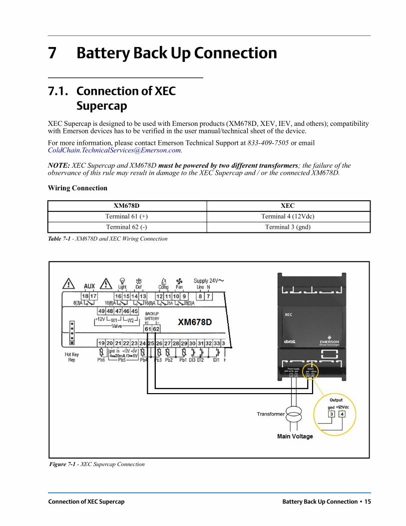
Connection of XEC Supercap Battery Back Up Connection • 15
7 Battery Back Up Connection
7.1. Connection of XEC Supercap
XEC Supercap is designed to be used with Emerson products (XM678D, XEV, IEV, and others); compatibility with Emerson devices has to be verified in the user manual/technical sheet of the device. For more information, please contact Emerson Technical Support at 833-409-7505 or email [email protected].
NOTE: XEC Supercap and XM678D must be powered by two different transformers; the failure of the observance of this rule may result in damage to the XEC Supercap and / or the connected XM678D.
Wiring Connection
XM678D XECTerminal 61 (+) Terminal 4 (12Vdc)Terminal 62 (-) Terminal 3 (gnd)
Table 7-1 - XM678D and XEC Wiring Connection
Figure 7-1 - XEC Supercap Connection

16 • XM678D I&O Manual 026-1224 Rev 1
7.2. Emerson ECP-024 ConnectionThe Emerson ECP-024 rechargeable accumulator can be connected to the XM678D to close the stepper valve in case of power interruption.
Wiring Connection
About conditions of use and limitation please refer to the ECP-024 manuals.
XM678D ECP-024Terminal 61 (+) Terminal +Terminal 62 (-) Terminal -
Table 7-2 - XM678D and ECP-024 Wiring Connection

Icons User Interface • 17
8 User Interface
8.1. Icons
8.2. Keyboard CommandsSingle commands:
• LIGHT relay: Press the light button
• AUX relay: Press the down arrow button
• Manual defrost: Press the defrost button for three (3) seconds
• ON/OFF: Press the ON/OFF button for three (3) seconds (if the function is enabled)
• ES: Press the ON/OFF button for three (3) seconds (if the function is enabled)
Figure 8-1 - XM678D Display
Cooling Output
Light Fan The output is activated when the icon is ON. A delay is present when the icon is blinking.
MEASUREMENT UNIT°C, Bar, and (time) are ON depending on the selection.
Defrost Auxiliary relay
Energy Saving Multimaster enabled
Generic alarm Clock/time
DURING PROGRAMMING: The measurement units of temperature and pressure will blink.
Table 8-1- XM678D Display Icons

18 • XM678D I&O Manual 026-1224 Rev 1
8.2.1. Double Commands
8.3. How to Modify the Air Temperature Regulation Setpoint
The thermostat setpoint is the value used to regulate the air temperature. The regulation output is controlled by the electronic valve or the relay.
In any case, it is possible to wait for about 10 seconds to exit. In order to show the air temperature set is sufficient to press and release the SET button, the value is displayed for about 60 seconds for a KEY COMBINATIONS.
+ Press for three (3) seconds to lock (Pon) or unlock (PoF) the keyboard.
Press both keys to exit the programming mode or from a menu; when on submenus EEV, pressing these keys return you to the previous level.
Press both keys for three (3) seconds to enter the first level of the programming mode.
Table 8-2 - Keyboard Double Commands
BEGIN Press the SET key for three (3) seconds (the measurement units will blink).
Value modification or Use the up arrow and down arrow keys to change the LS and US parameters value.
EXIT Press the SET key to save the value (the value will blink for two (2) seconds).
Table 8-3 - Modifying the Air Temperature Regulation Setpoint

How to Enter Pr2 How to Program the Parameters (Pr1 and Pr2) • 19
9 How to Program the Parameters (Pr1 and Pr2)
The device has two programming levels: Pr1 (direct access) and Pr2 (password-protected, access for higher level users).
9.1. How to Enter Pr2To enter Pr2 programming menu:
1. Press SET+ down arrow keys for three (3) seconds to enter Pr1 menu (the first label will display).
2. Press down arrow until the Pr2 label displays and then press SET.
3. A blinking “PAS” label displays. Wait for a few seconds.
4. When a blinking “0 - -” displays, enter the password [321] by pressing the up arrow and down arrow keys. Press SET to save.
GENERAL STRUCTURE: The first two items, rtC and EEV, are related to the submenus of the other parameters.
• Pressing the SET + up arrow keys on the rtC or EEV submenu returns you to the parameter list.
• Pressing the SET + up arrow keys on the parameter list exits the screen.
9.2. How to Move a Parameter From Pr1 to Pr2 Level and Vice Versa
Enter the Pr2 level and select the desired parameter then press the SET+ down arrow keys. If the LED on the left-hand side of the screen is ON, it means that the parameter is present in Pr1 level; if the LED is OFF, it means that the parameter is not present in Pr1 (Only Pr2).
ACCESS to Pr1
Press for three (3) seconds to enter the first programming level (Pr1).
Select item or Press the up arrow or down arrow key to select the parameter or submenu.
Show value Press the SET button.
Modify or Press the up arrow or down arrow key to change the value.
Confirm and store
Press SET (the value will blink for three (3) seconds and then display the next parameter).
EXITPress to exit the programming mode, or wait for 10 seconds to exit.
Table 9-1 - Programming the Parameters (Pr1 and Pr2)
Figure 9-1 - General Structure

20 • XM678D I&O Manual 026-1224 Rev 1
10 Fast Access MenuThe Fast Access menu contains the list of probes and values that are automatically emptied by the board such as the superheat and percentage of valve opening. The values: nP or noP stands for probe not present or value not emptied, and Err means the value is out of range, or the probe is damaged, not connected or configured incorrectly.
ENTERING THE FAST ACCESS MENU
Press and release the up arrow key. The duration of the menu in case of inactivity is about 3 minutes. Depending on the configuration of the board, the values display.
To select an entry, press the or , then press to view the
value or to move to the next value.
MAP Current map (0 to 3): it shows which map is used HM Access to clock menu or reset the RTC alarmAn Value of analog outputSH Value of superheat. nA= not AvailableoPP Percentage of valve openingdP1 (Pb1) Value read by probe 1dP2 (Pb2) Value read by probe 2dP3 (Pb3) Value read by probe 3dp4 (Pb4) Value read by probe 4dP5 (Pb5) Temperature read by probe 5 or value obtained from pressure transducerdP6 (Pb6) Value read by probe 6dPP Pressure value read by (Pb5) transducerrPP Virtual pressure probe, only on slaverPP Virtual pressure probe, only on slave. rCP Value of P4 remote probe for heaters. It is displayed only with P4C = LAn. If the value is not available “noP” label is displayed. dPr Virtual probe for room temperature regulation [rPA and rPb]rSE Real thermoregulation setpoint: the value includes the sum of SET, HES and/or the dynamic setpoint if the functions are enabled. L°t Minimum room temperature; H°t Maximum room temperature; tMd Time to next defrost (minutes) LSn Number of devices in the LAN LAn Address list of devices in the LAN GAL To see all the active alarms in each device connected to the LAN
EXIT Press together or wait the time out for 60 seconds.
Table 10-1 - Fast Access Menu

How to Move a Parameter From Pr1 to Pr2 Level and Vice Versa Multimaster Function Menu (SEC) • 21
11 Multimaster Function Menu (SEC)The function “section” SEC is enabled when the icon is lit. It allows entering in the remote programming mode from a keyboard not physically connected to the board through the LAN functionality.
EXAMPLES:1. To send a command to in all the devices connected to the LAN: enter multi-master menu. Select and confirm GLb.
Exit from multi-master menu. Enter the programming menu and set the parameter of global commands (from LMd to ACE). The new setting will be shared among the controllers connected to the LAN.
Figure 11-1 - LAN Connection
Action Button or display Notes
Enter menu Press the up arrow key for about three (3) seconds, the icon will be ON.
Waiting for action SEC The menu to change the section will be entered. SEC label will be displayed.
Enter section list Press SET to confirm. The following list will be available to select the proper network function.
Select proper function or LOCGLb
To gain access only to the local device.To share global command to all the devices connected to the LAN.
Confirm Select and confirm an entry by pressing SET button.
Exit menu Press SET and up arrow together or wait about 10 seconds.
Table 11-1 - Multimaster Function Menu Action Buttons
CAUTION! At the end of programming, select the LOC section to switch OFF the icon.

22 • XM678D I&O Manual 026-1224 Rev 1
11.1. Synchronized DefrostThe synchronized defrost allows multiple defrosts to be managed from different boards connected through the LAN connection. In this way, the boards can perform simultaneous defrosts with the possibility to end them in a synchronized manner.
The LSn and LAn parameter are used only to show the actual settings (read only). See Figure 11-2 for an example of configuration:
11.1.1. Daily Defrost From RTC: [EdF = rtC]
• IdF Parameter: For safety reason, force the value of Idf at +1 with respect to the interval between the two Ld parameters. The IdF timer is restarted after defrost and at every power ON.
• DEFROST START: At the time selected by the parameters Ld1 to Ld6 or Sd1 to Sd6.
• DEFROST END: If the probes reach the dtE temperature or for maximum MdF time.
• SAFETY and RtC or RtF ALARM: With clock alarm, the device will use the parameters IdF, dtE and MdF.
• MULTIMASTER DEFROST: All the probes with clock
CAUTION! In this case, the Adr parameter cannot be duplicated because defrost cannot be managed correctly.
BEGINPress for three (3) seconds, the rtC or other will be showed. The measurement unit blinks.
Find AdrPress the down arrow key several times to find the Adr parameter, then press SET.
Modify Adr or
Set the value of Adr parameter, then press SET to confirm the parameter.
EXITPress both keys to exit from menu or wait for about 10 seconds.
Table 11-2 - Synchronized Defrost Keys
Figure 11-2 - Configuration Example
CAUTION! Do not set [EdF = rtC] and [CPb = n].
Par Unit A (RTC)
Unit B (RTC)
Unit C (RTC)
Adr n N + 1 N + 2
IdF 9 hours safety 9 hours safety 9 hours safety
MdF 45 minutes safety
45 minutes safety
45 minutes safety
dtE 12°C safety 12°C safety 12°C safetyLd1 06:00 1° 06:00 1° 06:00 1° Ld2 14:00 2° 14:00 2° 14:00 2° Ld3 22:00 3° 22:00 3° 22:00 3°
Table 11-3 - Multimaster Defrost Example

Clock Setting and RTC Alarm Reset Commissioning • 23
12 Commissioning
12.1. Clock Setting and RTC Alarm Reset
If the clock is present: [EdF = rtC] enable the defrost from rtc [Ld1 to Ld6].
NOTE: The rtC clock menu is present also on the second level parameters.
12.2. Electronic Valve Settings
The following parameters needs to be checked:[1] Superheat temperature probe: NtC, PtC, Pt1000 with parameter P6C. The sensor has to be fixed at the end of the evaporator.[2] Pressure transducer: [4 to 20mA] or ratiometric P5C = 420 or 5Vr with parameter P5C.[3] Range of measurement: Check the conversion parameters, PA4 and P20, that are related to the transducer.
TRANSDUCER: For [-0.5/7Bar] or [0.5/8Bar abs], the correct setup is relative pressure with PA4 = -0.5 and P20 =7.0. For [0.5/12Bar abs], the correct setup is relative pressure with PA4 = -0.5 and P20 =11.00.Example or virtual pressure with unique [4 to 20mA] or [0-5V] transducer:
[4] From the EEV submenu: Select the correct kind of gas with the FTy parameter.[5] Use the following parameters to set up the correct valve drive (based on the valve data sheet of the manufacturer).
BEGINPress the up arrow key once to access the fast access menu.
DisplayHM identify the clock RTC, press
Display
HUr = hour -> press to save or change
MIn = minutes -> press to save or changeDo not use the other parameters if present.
EXITPress SET + up arrow keys for 10 seconds to reset the RTC alarm.
Table 12-1 - Clock Setting and RTC Alarm Reset
CAUTION! If the board displays the rtF alarm, it means that the board has to be replaced.
ParameterXM6x8D_1w/otransducer
XM6x8D_2 + withtransducer
XM6x8D_3 + w/otransducer
Adr n n+1 n+2LPP LPP=n LPP=Y LPP=n
P5CLAN or probe not connected
P5C=420 or 0-5V
LAN or probe not connected
PA4 not used -0.5 bar not usedP20 not used 11.0 bar not used
Table 12-2 - Example or virtual pressure with unique 4-20mA or 0-5V transducer

24 • XM678D I&O Manual 026-1224 Rev 1
13 Regulation for Superheat: Self Adaptive or Manual Operating Mode
13.1. General Considerations: Self Adaptive or Manual SH Control
The controller can regulate the superheat in manual or self adaptive mode, according to the value of the parameter AMS, auto-tuning enabling.
• With AMS = n: the normal SH regulation is performed.
• With AMS = y: the self adaptive SH regulation is performed.
13.2. Manual Operating Mode - AMS = NO
The temperature and SH regulation can be performed in two ways, according to the value of the parameter CrE: on/off or continuous. See the Standard temperature regulation in details below.
13.2.1. ON/OFF Temperature Regulation [CrE = n]
1. Temperature regulation is ON/OFF and it depends on the Setpoint and HY parameter (differential). Valve is closed when the temperature reaches the setpoint and open when the temperature is higher than setpoint + differential.
2. The superheat is regulated to be closer to its setpoint
3. With more pauses normally also the humidity is larger.
4. Regulation pauses can be realized using the Sti and Std parameters (during these pauses the valve is closed).
13.2.2. Continuous Temperature Regulation [CrE = Y] (With Superheat Regulation)
1. The HY parameter becomes the temperature band for PI control. A good default value is 5°C.
2. The regulation of injection is continuous and the cooling output is always ON. The icon is always ON except for the defrost phase.
3. The superheat is regulated following the SSH parameter.
4. Regulation pauses can be realized using Sti and Std parameters (during these pauses the valve is closed).
5. Increasing the Int integral time can decrease the speed of reaction of the regulator on the HY band.
13.3. Self Adaptive Operating Mode - AMS = YES
Auto-adaptive means to find and maintain the condition of the lowest super heating according to the load and environmental conditions present in a given time on the evaporator.The parameter ATU enables the self adaptive mode in the superheat regulation.In this functioning the values of Pb and inC parameter are automatically set by the controller according to the kind of applications and the response of the system.With the ATU = YES, CrE must be set to NO.The self adaptive algorithm does not affect the functions related to the forced opening of the valve in special situations, such as:
• Forced opening of the valve at start of regulation, parameter SFd (percentage) and SFd (time).
• Forced opening of the valve after defrost, parameter oPd (percentage) and Pdd (time).

Minimum Stable Superheat Search - AMS = YES, ATU = YES Regulation for Superheat: Self Adaptive or Manual Operating Mode • 25
13.4. Minimum Stable Superheat Search - AMS = YES, ATU = YES
With the parameter ATU, the minimum stable superheat search function is enabled.With ATU = Yes, controllers start searching the minimum stable value for the SH. The minimum admitted value in any case is LSH + 2°C (4°F). Take it into consideration, before setting the LSH value.
13.5. Valve Capacity Reducing - MNF Parameter
It is recommend to use the properly sized valve. In case fine tuning is required, the MnF parameter allows fine tuning of the valve to its evaporator.The regulation band is not affected from the modification of the MnF parameter.See the figure below (Figure 13-1) for the behavior of the capacity of the valve, when the MnF parameter is adjusted.
13.6. Pressure Filtering- AnP Parameter
For a good SH regulation, it is important to use a filtered value of the pressure. This can be done by the parameter AnP. Suggested values:
• From 1-5 evaporators for each racks: AnP = 5-6
• From 6-30 evaporators for each racks: AnP = 3-4
• More than 30 evaporators for each racks: AnP = 2-3
Figure 13-1 - Capacity of Valve in Adjusted MnF Parameter
NOTE: During the soft start phase (oPE, SFd), MnF parameter is not taken in consideration and the capacity of the valve is set by the parameters oPE and oPd, respectively.

26 • XM678D I&O Manual 026-1224 Rev 1
14 Display MessagesDisplay Causes Notes
KEYBOARD
1 nodNo display: the keyboard is trying to work with another board that is not working or not present
Press for three (3) seconds the up arrow, enter the SEC menu and select LOC entry.
2 Pon Keyboard is unlocked3 PoF Keyboard is locked4 rSt Alarm reset Alarm output deactivated.
5 noP, nPnA
Not present (configuration)Not available (evaluation)
6 noL The keyboard is not able to communicate with the XM678D
Verify the connection or call the Emerson Technical Service.
ALARM FROM PROBE INPUT
6
P1P2P3P4P5P6
PPFCPF
Sensor brake down, value out of range or sensor incorrectly configured P1C, P2C to P6C.
PPF can be showed by slaves of pressure that will not receive the value of pressure.
CPF is showed when the remote probe 4 is not working.
P1: the cooling output works with Con and COF,
With defrost probe on error the defrost is performed only at interval.
For P5, P6 and PPF: the percentage of the valve opening is fixed at PEO value.
TEMPERATURE ALARM
7 HA Temperature alarm from parameter ALU on probe rAL. Outputs unchanged.
8 LA Temperature alarm from parameter ALL on probe rAL. Outputs unchanged.
9 HA2 Second high temperature alarm. Output depends on setting.10 LA2 Second low temperature alarm. Output depends on setting.
DIGITAL INPUT ALARM
13 dA Door open alarm from input i1F, i2F or i3F = after delay d1d, d2d or d3d.
Cooling relay and fan follow the odc parameter. Cooling restart as specified on rrd parameter.
14 EA Generic alarm from digital input i1F, i2F, i3F = EAL.
15 CA Severe alarm of regulation lock from digital input i1F, i2F, i3F = bAL. Regulation output OFF.
16 PAL Pressure switch lock i1F, i2F o i3F = PAL. All the outputs are OFF.ELECTRONIC VALVE ALARM
17 LOP Minimum operating pressure threshold from LOP parameter.
The valve output increases its opening of dML quantity every second.
18 MOP Maximum operating pressure threshold from MOP parameter.
The valve output decreases its opening of dML quantity every second.
19 LSH Low superheating from LSH parameter and SHd delay.
The valve will be closed; the alarm will be showed after SHd delay.
Table 14-1 - Display Messages

Alarm Recovery Display Messages • 27
14.1. Alarm RecoveryProbe alarms P1, P2, P3, and P4 start some seconds after the fault in the related probe; they automatically stop some seconds after the probe restarts normal operation. Check the connections before replacing the probe.Temperature alarms HA, LA, HA2, and LA2 automatically stop as soon as the temperature returns to normal values.Alarms EA and CA (with i1F = bAL) recover as soon as the digital input is disabled. Alarm CA (with i1F = PAL) recovers only by switching OFF and ON the device.
20 HSH High superheating from HSH parameter and SHd delay. Only display.
CLOCK ALARM
21 rtC Clock settings lost. Defrost will be performed with IdF till restoring the settings of RTC.
22 rtF Clock damaged. Defrost will be performed with IdF.OTHERS
23 EE EEPROM serious problem. Output OFF.24 Err Error with upload/download parameters. Repeat the operation.25 End Parameters have been correctly transferred. 26 dEF Defrost is in progress27 cLn Cleaning function is active
Display Causes Notes
Table 14-1 - Display Messages

28 • XM678D I&O Manual 026-1224 Rev 1
15 Electronic Expansion Valve Menu (For XM678D Only)
1. Enter the Programming mode by pressing the SET and DOWN key for few seconds (measurement unit starts blinking).
2. Press arrow until instrument shows EEU label.
3. Press SET, then you will be in the EEV function menu.Table 15-1 - Commands

Temperature Probe Reference for Regulation Controlling Loads • 29
16 Controlling Loads
16.1. Temperature Probe Reference for Regulation
Up to 5 temperature probe can be used for the temperature regulation. It is possible to set the probes used for temperature regulation. Up to 5 Temperature inputs Pb1, Pb2, Pb3, Pb4, Pb6, can be used.
To support above function, the parameters rPA, rPb, rP3, rP4, rP5 are used. Which temperature probe methods of combine is set by par. rPd among the following: Average, Minimum, Maximum, First, or Mix. rPd = Avr Average– Average of all valid probes defined as Regulation Probe by par. (rPA, rPb, rP3, rP4, rP5) rPd = Min Minimum – Minimum of all valid probes defined as Regulation Probe by par. (rPA, rPb, rP3, rP4, rP5) rPd = MAS Maximum – Maximum of all valid probes defined as Regulation Probe by par. (rPA, rPb, rP3, rP4, rP5) rPd = FrS First – First valid probe defined as Regulation Probe by par. (rPA, rPb, rP3, rP4, rP5) rPd = rPE Mix – This is currently done with “rPE” parameter.
16.1.1. Sensor FailureIn case of multiple temperature sensor regulation: (rPd = Aur, Min, Max or rPE), and with sensor failure, the remaining sensors are used for the regulation. In case of all sensors failure, the valve opens at PEO percentage
16.2. Dual Temp Mode Operation
Controller can have up to 4 pre-set regulation. The preset regulation is set in the parameter MAP. By digital input or supervising system is possible to enable the second regulation mode, set in the parameter M2P. In this way a dual temp case can be easily set and controlled.
16.2.1. Second Map Function by Digital Input Configuration
By setting on digital input among i1F, i2F, i3F as the “nt” the map set in the parameter M2P is loaded when the digital input is enabled.
16.3. The Solenoid ValveThe regulation is performed according to the temperature measured by the thermostat probe that can be physical probe or virtual probe obtained by a weighted average between two probes (see parameters table description) with a positive differential from the setpoint. If the temperature increases and reaches setpoint plus differential the solenoid valve is opened and then it is closed when the temperature reaches the setpoint value again. In case of fault in the thermostat probe the opening and closing time of solenoid valve is configured by “Con” and “CoF” parameters.
Figure 16-1 - Control With Analog Output

30 • XM678D I&O Manual 026-1224 Rev 1
16.4. Standard Regulation and Continuous Regulation
The regulation can be performed in two ways: the goal of the first way (standard regulation) is reaching the best superheat via a classic temperature regulation obtained using hysteresis. The second way, permits to use the valve to realize an high performance temperature regulation with a good factor of superheat precision. This second possibility, it can be used only in centralized plants and it is available only with electronic expansion valve by selecting CrE = Y parameter.
16.4.1. First Kind of Regulation: In this case, the Hy parameter is the differential for standard ON/OFF regulation. During this phase the valve will maintain the SH setpoint
16.4.2. Second Kind of Regulation – Continuous Regulation:
In this case, the Hy parameter is the proportional band of PI in charge of room temperature regulation and we advise to used at least Hy=5.0°C/10°F. The int parameter is the integral time of the same PI regulator. Increasing int parameter the PI regulator become slow in reaction and of course is true vice versa. To disable the integral part of regulation you should set int=0.
16.5. Pump Down Before Defrost
The following parameters has been added: Pdt pump down type (nu; FAn; F-C)
With Pdt = nu, the pump down is not enabled. With Pdt = Fan, when a defrost trigger is given:
a. Compressor relay will be open. b. EEV valve (if present):
i. Will be closed with CrE = n, y ii. Will be open with CrE =EUP or EU5
c. Fan will be forced on for Pdn time
With Pdt = F-C, when a defrost trigger is given: a. EEV valve (if present): i. Will be closed with CrE = n, y
ii. Will be open with CrE =EUP or EU5 b. Compressor relay and Fan will be forced on for
Pdn time
Pdn pump down duration (0 to 255 minutes)
16.6. Defrost
16.6.1. Defrost StartingIn any case, the device checks the temperature that is read by the configured defrost probe before starting the defrost, after that:
• (If RTC is present) Two defrost modes are available through the tdF parameter: defrost with electrical heater and hot gas defrost. The defrost interval is controlled by the parameter EdF: (EdF = rtC) defrost is made in real time depending on the hours set in the parameters Ld1 to Ld6 in workdays and in Sd1 to Sd6 on holidays; (EdF = in) the defrost is made every IdF time.
• Defrost cycle starting can be operated locally (manual activation by means of the keyboard or digital input or end of interval time) or the command can come from the master defrost unit of the LAN. In this case, the controller will operate the defrost cycle following the parameters it has programmed. At the end of the drip time, it will wait until all the other controllers of the LAN finish their defrost cycle before restarting the normal regulation of the temperature according to dEM parameter.
• Each time any of the LAN controller begins a defrost cycle, it issues the command into the network making all the other controllers start their own cycle. This allows a perfect synchronization of the defrost in the whole multiplexed cabinet according to the LMd parameter.
• Differential defrost: Selecting the dPA and dPb probes and by changing the dtP and ddP parameters, the defrost can be started when the difference between dPA and dPb probes is lower than dtP for all ddP time. This is useful to start defrost when a low thermal exchange is detected. If [ddP = 0], this function is disabled.

On Demand Defrost Controlling Loads • 31
16.6.2. Minimum Defrost TimeThe “ndt” (0 to MnF) Minimum Defrost Time, set the minimum defrost duration, when the defrost is ended by evaporator temperature probe. The ndt time is taken in account every time the defrost is trigged, independently form the value of end defrost temperature probe and end defrost digital input status.
16.6.3. Defrost Ending• When defrost is started via rtC, the maximum
defrost duration is obtained from the Md parameter and the defrost end temperature is obtained from the dtE parameter (and dtS if two defrost probes are selected).
• If dPA and dPb are present and [d2P = Y], the device stops the defrost procedure when dPA is higher than dtE temperature and dPb is higher than dtS temperature.
At the end of defrost, the drip time is controlled through the Fdt parameter.
16.6.4. Kind of DefrostThe kind of defrost is set by parameter tdF among the following possibilities.tdF = Air: natural defrost. Defrost is made by
opening the compressor/solenoid relay. The fan during defrost depends on the parameter Fnc. Defrost relay is off. The valve is closed
tdF = EL: defrost with electrical heater: Defrost is made by opening the compressor/solenoid relay. The fan during defrost depends on the parameter Fnc. Defrost relay is on. The valve is closed
tdF = in: hot gas defrost. Defrost is made by closing the compressor/solenoid relay. The fan during defrost depends on the parameter Fnc. Defrost relay is on. The valve opening percentage during the defrost is set by the par. oPd.
16.7. On Demand Defrost
16.7.1. Description Controller can perform on demand defrost. It is based on the behavior of evaporator temperature. Controller monitors the evaporator temperature and triggers a defrost if some conditions are satisfied. For defrost efficiency it is important to place the “end defrost probe”, usually P2, in the coldest place of the evaporator, usually immediately after the expansion valve. NOTE: Because of different type of evaporators and consequentially behaviors, it is recommended to test and validate this algorithm in a climatic chamber before applying it in the field.

32 • XM678D I&O Manual 026-1224 Rev 1
16.7.2. Parameters and SettingsThe «On Demand Defrost» can be activated with the following settings: CrE=”n”, EdF=”Aut” cdt: Evaporator temperature differential to trigger a defrost (default cdt = 4°K) nbd: Minimum compressor run before automatic defrost (or minimum time of activation of solenoid valve) it has to be set properly. It prevents defrost from starting (default nbd = 4.0h) Mbd: Max compressor run before automatic defrost (or max time of activation of solenoid valve): it has to be set properly. If reached a defrost is triggered (default Mbd = 16.0h) nct: Minimum evap. temperature, it has to be set properly. a defrost is triggered when this temperature reached (default nct = -30°C) NOTE: With CrE =”y” or CrE =”EUP” or CrE=EU5 only «RTC defrost» and «interval defrost» are allowed. With EdF =”Aut” & CrE =”y” or CrE =”EUP” or CrE=EU5 the «interval defrost» will be performed, as with EdF = in
16.7.3. Exceptions 1. A defrost cannot be triggered if the compressor
has not ran more than minimum time (nbd parameter) since the last defrost or initial power up. (Resolution hh.m)
2. If the compressor has ran for more than maximum time since the last defrost or initial power up (Mbd parameter), a defrost is triggered regardless of coil temperature.
3. If the coil temperature reaches very low temperature, (nct parameter), a defrost is triggered regardless of cdt value.
16.8. Fans
16.8.1. Control with RelayThe fan control mode is selected by means of the FnC parameter:
• C-n = Running with the solenoid valve, OFF during defrost
• C-Y = Running with the solenoid valve, ON during defrost
• O-n = Continuous mode, OFF during defrost
• O-Y = Continuous mode, ON during defrost
An additional parameter FSt provides the setting of the temperature, detected by the evaporator probe, above which the fans are always OFF. This can be used to verify that air is circulated only if this temperature is lower than set in the FSt.
16.8.2. Control With Analog Output (If Present)
The modulating output [trA = rEG] works in a proportional manner (excluding the first AMt seconds where the fans speed is the maximum; 10 seconds is the minimum value). The regulation setpoint is relative to the regulation setpoint and is indicated by ASr, the proportional band is always located above the [SET + ASr] value and its value is PbA. The fans are at minimum speed AMi when the temperature read by the fan probe is [SET + ASr] and the fan is at maximum speed (AMA) when the temperature is [SET + ASr + PbA].
16.9. Anti-Sweat HeatersAnti-sweat heater regulation can be performed with the on board relay (if OA6 = AC) or with the analog output (if present by setting trA = AC). However, the regulation can be performed in two ways:
• Without real dewpoint information: in this case the default value for dewpoint is used (SdP parameter).
• Receiving dewpoint from XWEB5000 system: the SdP parameter is overwritten when a valid value for dewpoint is received from XWEB. In case the
Figure 16-2 - Control With Analog Output

Anti-Sweat Heaters Controlling Loads • 33
XWEB link is lost, SdP is the value that will be used for safety.
The best performance can be obtained using probe 4. In this case, the regulation follows the chart illustrated in Figure 16-3:
Probe 4 should be placed on the showcase glass. For each cabinet, only one probe 4 (P4) can be used; the P4 will send its value to the other sections that are connected to the LAN.
Figure 16-3 - Anti-Sweat Heaters

34 • XM678D I&O Manual 026-1224 Rev 1
Functioning with Probe 4 within the LAN:
Functioning Without Probe 4:
In this case, regulation is performed by switching the auxiliary relay ON and OFF on a 60-minutes time base. The ON time will be the AMt value, so that the relay will be ON for AMt minutes and OFF for [60-AMt] minutes.In case of P4 error or if P4 is absent, the output is at AMA value for the AMt time then the output is at 0 value for the time [255 - AMt] time performing a simple PWM modulation.
16.10. Cleaning Mode Function by Digital Input Configuration
The “cLn” value is added to the functions of the digital input. The function has the same basic features of the stand by function, but with the following differences:
a. By the parameter LcL (No, Yes) it is possible to set if the light is on or off during cleaning mode. This parameter LcL can be override by light button or by Light on/off MODBUS command.
b. By the parameter FcL (No, Yes) it is possible to set if the fan is on or off during cleaning mode. In case of fan on, the FSt parameter (fan stop temperature) is override.
16.10.1. Display During the Cleaning Status, the display shows the “cLn” message.
16.11. Auxiliary OutputThe auxiliary output is switched ON and OFF by means of the corresponding digital input or by pressing and releasing the down arrow key.
Parameter XM6x8D_1Without Probe 4
XM6x8D_2 + With Probe 4 XM6x8D_3+ Without Probe 4
Adr n n + 1 n + 2LCP LCP = n LCP = Y LCP = n
P4C LAN or probe not connected P4C = NTC, PtC or PtM LAN or probe not connected
trA trA = AC if the device has the analog outputOA6 OA6 = AC if the device will use the AUX relay for regulation
Table 16-1 - Functioning with Probe 4 within the LAN
Parameter XM6x8D Without Probe 4P4C nPAMt % of ON
Table 16-2 - Functioning Without Probe 4

Auxiliary Output Parameter List • 35
17 Parameter ListParameter Description
REGULATIONSet Temperature setpoint (LS to US) rtC Access to CLOCK submenu (if present)
EEU Access to EEV submenu (only XM678D)
Hy Differential: (0,1 to 25,5°C; 1 to 45°F): Intervention differential for setpoint, always positive. Solenoid valve Cut IN is Setpoint Plus Differential (Hy). Solenoid valve Cut OUT is when the temperature reaches the setpoint.
Int Integral time for room temperature regulation (Only XM678D): (0 to 255 seconds) Integral time for room temperature PI regulator. 0 = no integral action.
CrE Continuous regulation activation (Only XM678D): (N to Y) N = standard regulation; Y= continuous regulation. Use it only in centralized plants.
LS Minimum setpoint limit: (-55.0°C to SET; -67°F to SET) Sets the minimum acceptable value for the setpoint.
US Maximum setpoint limit: (SET to 150°C; SET to 302°F) Set the maximum acceptable value for setpoint.
OdS Outputs activation delay at start up: (0 to 255 minutes) This function is enabled at the initial start up of the instrument and inhibits any output activation for the period of time set in the parameter. (AUX and Light can work)
AC Anti-short cycle delay: (0 to 60 minutes) Interval between the solenoid valve stop and the following restart.
CCt Compressor ON time during continuous cycle: (0.0 to 24.0 hours; resolution 10 minutes) Allows to set the length of the continuous cycle: compressor stays on without interruption for the CCt time. Can be used, for instance, when the room is filled with new products.
CCS Setpoint for continuous cycle: (-55 to 150°C / -67 to 302°F) It sets the setpoint used during the continuous cycle.
Con solenoid valve ON time with faulty probe: (0 to 255 minutes) Time during which the solenoid valve is active in case of faulty thermostat probe. With COn = 0 solenoid valve is always OFF.
CoF solenoid valve OFF time with faulty probe: (0 to 255 minutes) Time during which the solenoid valve is off in case of faulty thermostat probe. With COF = 0 solenoid valve is always active.
DISPLAY
CF Temperature measurement unit: °C= Celsius; °F= Fahrenheit.WARNING: When the measurement unit is changed the parameters with temperature values have to be checked.
PrU Pressure mode: (rEL or AbS) It defines the mode to use the pressure. WARNING: The setting of PrU is used for all the pressure parameters. If PrU = rEL all pressure parameters are in relative pressure unit, if PrU = AbS all pressure parameters are in absolute pressure unit. (Only XM678D)
PMU Pressure measurement unit: (bAr – PSI - MPA) It selects the pressure measurement units. MPA= the value of pressure measured by kPA*10. (Only XM678D)
PMd Way of displaying pressure : (tEM - PrE) It permits showing the value measured by pressure probe with tEM = temperature or by PrE = pressure; (Only XM678D)
rES Resolution (for °C): (in = 1°C; dE = 0.1 °C) Allows decimal point display.
Table 17-1 - Parameter List

36 • XM678D I&O Manual 026-1224 Rev 1
rEP Resolution for % value: (in = integer; dE = with decimal point) Allows decimal point display for percentage values.
Lod Instrument display: (nP; P1; P2, P3, P4, P5, P6, tEr, dEF) It selects which probe is displayed by the instrument. P1, P2, P3, P4, P5, P6, tEr= virtual probe for thermostat, dEF = virtual probe for defrost.
rEd Remote display: (nP; P1; P2, P3, P4, P5, P6, tEr, dEF) It selects which probe is displayed by the X-REP. P1, P2, P3, P4, P5, P6, tEr= virtual probe for thermostat, dEF = virtual probe for defrost.
dLy Display delay: (0 to 24.0 minutes; resolution 10 seconds) When the temperature increases, the display is updated of 1 °C/1°F after this time.
rPA Regulation probe A: (nP; P1; P2, P3, P4, P6) First probe used to regulate room temperature. If rPA=nP the regulation is performed with real value of rPb.
rPb Regulation probe B: (nP; P1; P2, P3, P4, P5) Second probe used to regulate room temperature. If rPb=nP the regulation is performed with real value of rPA.
rP3 Regulation probe 3: (nP; P1; P2, P3, P4, P6) Third probe used to regulate room temperature, with rPd = Aur or Min or MA or FrS.
rP4 Regulation probe 4: (nP; P1; P2, P3, P4, P6) Fourth probe used to regulate room temperature, with rPd = Aur or Min or MA or FrS.
rP5 Regulation probe 5: (nP; P1; P2, P3, P4, P6) Fifth probe used to regulate room temperature, with rPd = Aur or Min or MA or FrS.
rPd
Temperature Regulation Strategy: (Aur, Min, MAS, FrS, rPE) Aur: Average of all valid probes defined as Regulation Probe Min: Minimum value of all valid probes defined as Regulation Probe MaS: Maximum of all valid probes defined as Regulation Probe FrS: First valid probe defined as Regulation Probe rPE: Mix between rPA and rPb defined by rPE parameter
rPE Regulation virtual probe percentage: (0 to 100%) It defines the percentage of the rPA respect to rPb. The value used to regulate room temperature is obtained by: Value_for_room = (rPA*rPE + rPb*(100-rPE))/100
ELECTRONIC EXPANSION VALVE SUBMENU (Only XM678D)
Parameter Description
Table 17-1 - Parameter List

Auxiliary Output Parameter List • 37
FtY
Kind of gas:
ATU Self adaptive SH regulation enabling (No; Yes) This parameter enables the self adaptive regulation of the superheat. CrE = no must to be set, when this function is enabled.
AMS Minimum STABLE superheat search (No; Yes) This parameter enables the search of the minimum stable superheat. The lowest admitted value is LSH+2°C.
SSH Superheat setpoint: [0.1°C to 25.5°C] [1°F to 45°F] It is the value used to regulate superheat.
SHy Differential for low superheat function: This value is used by X-WEB with XeCO2 function. When the monitoring system enable the low superheat Shy is subtracted to the SSH setpoint(-12.0 to 12.0°C).
Pb Proportional band: (0.1 to 60.0 / 1 to 108°F) PI proportional band.
PbH Dead band for superheat regulation: It is a band across the SH setpoint, inside this band the valve opening percentage is not updated.
rS Band Offset: (-12.0 to 12.0°C / -21 to 21°F) PI band offset.inC Integration time: (0 to 255 seconds) PI integration time.dFC Derivative time: (0 to 255 seconds) PID derivative time.PEd Delay before stopping regulation with probe error: 0 to 239 seconds - On (240)
Parameter Description
Table 17-1 - Parameter List
LABEL REFRIGERANT OPERATING RANGE
R22 r22 -58 to 120°F / -50 to 60°C
134 r134A -58 to 120°F / -50 to 60°C
290 r290 – Propane -58 to 120°F / -50 to 60°C
404 r404A -94 to 120°F / -70 to 60°C
47A r407A -58 to 120°F / -50 to 60°C
47C r407C -58 to 120°F / -50 to 60°C
47F r407F -58 to 120°F / -50 to 60°C
410 r410A -58 to 120°F / -50 to 60°C
448 r448A -49 to 120°F / -45 to 60°C
449 r449A -49 to 120°F / -45 to 60°C
450 r450A -49 to 120°F / -45 to 60°C
452 r452A -94 to 120°F / -70 to 60°C
507 r507 -94 to 120°F / -70 to 60°C
513 r513A -49 to 120°F / -45 to 60°C
CO2 r744 - Co2 -58 to 77°F / -50 to 25°C
15b r515b -22 to 120°F / -30 to 60°C
54A r454A -58 to 120°F / -50 to 60°C
54b r454B -58 to 120°F/ -50 to 60°C
54C r454C -58 to 120°F / -50 to 60°C
55A r455A -40 to 120°F / -40 to 60°C
4yF r1234yf -58 to 120°F / -50 to 60°C
4EE r1234ze -58 to 120°F / -50 to 60°C

38 • XM678D I&O Manual 026-1224 Rev 1
PEO Probe Error opening percentage: (0 to 100%) If a probe error occurs, valve opening percentage is PEo.
SFd Start Function duration: (0.0 to 42.0 minutes: resolution 10 seconds) It sets start function duration and post-defrost duration. During this phase the SH alarms are overridden.
SFP Start opening Percentage: (0 to 100%) Opening valve percentage when start function is active. This phase duration is SFd time.
OHg Opening Percentage during hot gas defrost: (0 to 100%) Opening valve percentage when hot gas defrost is active.
Pdd Post Defrost Function duration: (0.0 to 42.0 minutes; resolution 10 seconds) It sets start function duration and post-defrost duration. During this phase the alarms are overridden.
OPd Opening Percentage after defrost phase: (0 to 100%) Opening valve percentage when after defrost function is active. This phase duration is Pdd time.
LnF Minimum opening percentage at normal Functioning: (0 to 100%) During regulation it sets the minimum valve opening percentage; (0 to MnF%)
MnF Maximum opening percentage at normal Functioning: (LnF to 100) During regulation it sets the maximum valve opening percentage.
dCL Regulation off delay, when the setpoint is reached (0 to 255 seconds)
Fot Forced opening percentage: (0 to 100% - nu) It permits to force the valve opening to the specified value. This value overwrite the value calculated by PID algorithm. NOTE: To obtain the correct superheat regulation you have to set Fot = nu.
LPL Lower Pressure Limit for superheat regulation: (PA4 to P20 bar / psi / kPA*10) When suction pressure comes down to LPL the regulation is performed with a LPL fixed value for pressure, when pressure comes back to LPL the normal pressure value is used. (related to PrM parameter)
MOP Maximum Operating Pressure threshold: (PA4 to P20 bar / psi / kPA*10) If suction pressure exceeds maximum operating pressure value, instrument signals situation with MOP alarm. (related to PrM parameter)
dMP Delay for Maximum Operating Pressure threshold alarm signaling: (0 to 255 seconds) When a MOP alarm occurs it is signaled after dMP time.
LOP Minimum Operating Pressure threshold: (PA4 to P20 bar / psi / kPA*10) If the suction pressure comes down to this value a low pressure alarm is signaled with LOP alarm. (related to PrM parameter)
dLP Delay for Minimum Operating Pressure threshold alarm signaling: (0 to 255 seconds) When a LOP alarm occurs it is signaled after dMP time
dML Opening steps variation during MOP and LOP: (0 to 100%) When a MOP alarm occurs valve will close of the dML percentage every cycle period until MOP alarm is active. When LOP occurs valve will open of the dML percentage every cycle period until LOP alarm is active.
AAS Low superheat alarm with "XeCO2 function active: N = no superheat alarm, Y= Low superheat alarm is still signaled.
HSH High Superheat alarm: (LSH to 80.0°C / LSH to 144°F) When superheat exceeds this value an high superheat alarm is signaled after interval SHd.
LSH Low Superheat alarm: (0.0 to HSH °C / 0 to HSH °F) When superheat goes down to this value a low superheat alarm is signaled after interval SHd.
dHS High superheat alarm activation delay: (0.0 to 42.0 minutes: resolution 10 seconds) When a high superheat alarm occurs, the time dHS has to pass before alarm signaling.
dLS Low superheat alarm activation delay: (0.0 to 42.0 minutes: resolution 10 seconds) When a low superheat alarm occurs, the time SHd has to pass before alarm signaling.
Parameter Description
Table 17-1 - Parameter List

Auxiliary Output Parameter List • 39
LSA Opening percentage decrease with low Superheat alarm: (0 to 100%)
FrC Fast-recovery Constant: (0 to 100 seconds) Permits to increase integral time when SH is below the setpoint. If FrC = 0 fast recovery function is disabled.
AnP
Pressure filter (0 to 100) It uses the last average values of the pressure to calculate the superheat. E.I. with AnP = 5 controller uses the average pressure in the last 5 seconds to calculate the SH. NOTE: Avoid values higher than 10.
Ant
Temperature filter (0 to 100) It uses the last average values of the temperature to calculate the superheat. E.I. with Ant = 5 controller uses the average temperature in the last 5 seconds to calculate the SH. NOTE: Avoid values higher than 10.
SLb Reaction time (0 to 255 seconds): Time to update the valve open percentage. EI. With SLb = 24: the valve open percentage is updated every 24 seconds.
tEP
Predefined valve selection: [0 to 10] if [tEP = 0] the user has to modify all the parameters of configuration in order to use the valve. If tEP is different from 0 the device performs a fast configuration of the following parameters: LSt, uSt, Sr, CPP, CHd. To select the right number please read the following table.If tEP is different from 0 previous configuration of LSt, uSt, Sr, CPP and CHd are overwritten.
tEUType of Stepper motor: [uP-bP] It permits to select the kind of valve. uP = 5 - 6 wires unipolar valves; bP = 4 wires bipolar valves; NOTE: By changing this parameter the valve has to be reinitialized.
bdM bipolar valve piloting: ["UAM"(0=Wave Mode) - "noM"(1=Normal Mode)] Bipolar valve pilot mode: Wave Mode - Normal Mode
HFSKind of motor movement: (HAF; FUL) HAF = Half step. Use this setting for the unipolar valve. FUL = Half step. Use this setting for the bipolar valve.
Parameter Description
Table 17-1 - Parameter List
tEP ModelLSt
(steps*10)
uST(steps*1
0)
CPP(mA*1
0)
CHd(mA*1
0)
Sr(step/
s)
tEu(bip/unip)
HSF(Half/Full)
0 Manual settings Par Par Par Par Par Par Par
1Danfoss EST-25/50
7 262 10 10 300 bP FUL
2 Danfoss EST-100 10 353 10 10 300 bP FUL
3Danfoss EST-250/400
11 381 10 10 300 bP FUL
11Emerson EX4/EX5/EX6
5 75 50 10 300 bP FUL

40 • XM678D I&O Manual 026-1224 Rev 1
LSt
Minimum number of steps: [0 to USt] It permits to select the minimum number of steps. At this number of steps the valve should be closed. So it is necessary the reading of manufacturer data sheet to set correctly this parameter. It is the minimum number of steps to stay in advised range of functioning. NOTE: By changing this parameter the valve has to be reinitialized. The device performs this procedure automatically and restarts its normal functioning when the programming mode ends.
USt
Maximum number of steps: [LSt to 800*10] It permits to select the maximum number of steps. At this number of steps the valve should be completely opened. Read the data sheet provided by manufacturer of the valve to set correctly this parameter. It is the maximum number of steps to stay in advised range of functioning. WARNING: By changing this parameter the valve has to be reinitialized. The device performs this procedure automatically and restarts its normal functioning when the programming mode ends.
ESt
Extra step during closing phase: (0 to 255 *10) It sets the number of extra steps the controller performs, when the valve is closed at start up, and during the pauses of regulation, to force the closure of the valve. NOTE: To set ESt the following steps has to be done:
1. Set the kind of valve by the parameter tEP. This pre-set the parameters related to the valve 2.Set the right value of ESt
Sr Step rate [10 to 600 step/second] It is the maximum speed to change step without losing precision (means without losing steps). It is advised to stay under the maximum speed.
CPP Current per phase (only bipolar valves): [0 to 100*10mA] It is the maximum current per phase used to drive valve. It is used only with bipolar valves.
CHd Holding current per phase (only bipolar valves): [0 to 100*10mA] it is the current per phase when the valve is stopped for more than 4 minutes. It is used only with bipolar valves.
GtCMinimum Interval to enable calibration cycles with extra steps ESt: [0 to GtH hour)] Indicates the number of hours after which the valve calibration is enabled (with extra steps ESt) when the regulation closes the valve at 0%.
GtH Interval between automatic valve calibration cycles: [GtC to 255 (ore)]
dtyPilot duty: (20 to 100%) with dtY = 100, the valve is moved without interruption, with dtY = 60 the valve is moved with a pilot duty of 60%: for 0.6s on and then for 0.4s off till the final position is reached.
DEFROST
dPA Defrost Probe A: (nP; P1; P2, P3, P4, P6) First probe used for defrost. If rPA = nP the regulation is performed with real value of dPb.
dPb Defrost Probe B: (nP; P1; P2, P3, P4, P6) Second probe used for defrost. If rPB = nP the regulation is performed with real value of dPA. Value_for_defrost= (dPA*dPE + dPb*(100-dPE))/100
tdF
Defrost type: (Air, EL, in) Air = Air defrost (relay is not switched on during defrost) EL = Defrost with electrical heaterin = Hot gas defrost
EdF Defrost mode: (rtc – in- Aut) (only if RTC is present) rtc= defrost activation via RTC; in= defrost activation with idf; AUt = on demand defrost.
Srt Heater setpoint during defrost: (-55.0 to 150.0°C; -67 to 302°F) If tdF=EL during the defrost the defrost relay perform an ON/OFF regulation with Srt as setpoint.
Hyr Differential for heater: (0.1°C to 25.5°C, 1°F to 45°F) The differential for heater.
Parameter Description
Table 17-1 - Parameter List

Auxiliary Output Parameter List • 41
tod Time out for heater: (0 to 255 minutes) If the defrost probe temperature is bigger than Srt for all tod time the defrost ends although the defrost probe temperature is lower than dtE or dtS. It permits to reduce defrost duration.
d2P Defrost with two probes: (N – Y) N= only the dPA probe is used to defrost management; Y= defrost is managed with dPA probe and dPb probe. Defrost can performed only if both probe value are lower than dtE for dPA probe and dtS for dPb probe.
dtE Defrost termination temperature (Probe A): (-55, 0 to 50, 0°C; -67 to 122°F) (Enabled only when the evaporator probe is present) sets the temperature measured by the evaporator probe dPA which causes the end of defrost.
dtS Defrost termination temperature (Probe B): (-55, 0 to 50, 0°C; -67 to 122°F) (Enabled only when the evaporator probe is present) sets the temperature measured by the evaporator probe dPb which causes the end of defrost.
IdF Interval between defrosts: (0 to 120 hours) Determines the time interval between the beginning of two defrost cycles.
idE
Time to next defrost log into not volatile memory No: Time to next defrost is not logged into no volatile memory, this means controller will use the idF interval after a power off. E.I. idF = 8: controller performs a defrost every 8 hours. If controller is switched off, independently from when last defrost happened, at power on it will do the first defrost after 8 hours. Yes: Time to next defrost is logged into no volatile memory, this means controller will use it after a power off. E.I. idF = 8: controller performs a defrost every 8 hours. If controller is switched off 6 hours after last defrost, at power on it will do the first defrost after 2 hours (6+2 = 8). It is useful in places subjected to frequent power outages.
ndt Minimum duration of defrost: (0 to MdF minute) It sets the minimum defrost duration, independently form the temperature reached by the end defrost probes.
MdF Maximum duration of defrost: (ndt to 255 minutes) When dPA and dPb are not present, it sets the defrost duration, otherwise it sets the maximum duration for defrost.
dSd Start defrost delay: (0 to 255 minutes) This is useful when different defrost start times are necessary to avoid overloading the plant.
dFd Display during defrost: rt = real temperature; it = temperature reading at the defrost start; Set = setpoint; dEF = “dEF” label.
dAd Defrost display time out: (0 to 255 minutes) Sets the maximum time between the end of defrost and the restarting of the real room temperature display.
Fdt Drain down time: (0 to 255 minutes) Time interval between reaching defrost termination temperature and the restoring of the control’s normal operation. This time allows the evaporator to eliminate water drops that might have formed due to defrost.
dPo First defrost after start-up: Y = Immediately; N = after the IdF time
dAF Defrost delay after continuous cycle: (0 to 23.5 hours) Time interval between the end of the fast freezing cycle and the following defrost related to it.
PUMP DOWN
Pdt
Pump down type (nu, FAn, F-C) nu: Pump down disabled FAn: Pump down enabled. Fan is activated for pump down duration, compressor relay/solenoid valve is switched off with CrE = N/Y o or activated with CrE = EUP or EU5. F-C: Pump down enabled. Fan and compressor relay are activated for pump down duration. See above for solenoid valve behavior.
Pdn Pump down duration (0 to 255 minutes) ON DEMAND DEFROST
Parameter Description
Table 17-1 - Parameter List

42 • XM678D I&O Manual 026-1224 Rev 1
Ctd Differential for defrost start (0.1°C to 25.5°C, 1°F to 45°F) nbd Minimum Compressor run time before defrost (0.0 to 24 hours, 00 minutes) Mdb Maximum Compressor run time before defrost (0.0 to 24 hours, 00 minutes) nct Minimum coil temperature to trigger a defrost (-55.0°C to 150.0°C; 67°F to 302°F]
FAN
FAP Fan probe A: (nP; P1; P2, P3, P4, P5) First probe used for fan. If FPA = nP the regulation is performed with real value of FPB.
FnC Fan operating mode: C-n = running with the solenoid valve, OFF during the defrost; C-y = running with the solenoid valve, ON during the defrost; O-n = continuous mode, OFF during the defrost; O-y = continuous mode, ON during the defrost.
Fnd Fan delay after defrost: (0 to 255 minutes) The time interval between the defrost end and evaporator fans start.
FCt Temperature differential avoiding short cycles of fans (0.0°C to 50.0°C; 0°F to 90°F) If the difference of temperature between the evaporator and the room probes is more than the value of the Fct parameter, the fans are switched on.
FSt Fan stop temperature: (-50 to 110°C; -58 to 230°F) Setting of temperature, detected by evaporator probe, above which the fan is always OFF.
FHy Differential to restart fan: (0.1°C to 25.5°C) (1°F to 45°F) when stopped, fan restarts when fan probe reaches FSt-FHy temperature.
tFE Fan regulation by temperature during defrost (N,Y)
Fod Fan activation time after defrost: (0 to 255 minutes) It forces fan activation for indicated time.
Fon Fan ON time: (0 to 15 minutes) with Fnc = C_n or C_y, (fan activated in parallel with compressor). it sets the evaporator fan ON cycling time when the compressor is off. With Fon =0 and FoF ≠ 0 the fan are always off, with Fon=0 and FoF =0 the fan are always off.
FoF Fan OFF time: (0 to 15 minutes) with Fnc = C_n or C_y, (fan activated in parallel with compressor). it sets the evaporator fan off cycling time when the compressor is off. With Fon = 0 and FoF ≠ 0 the fan are always off, with Fon = 0 and FoF = 0 the fan are always off.
MODULATING OUTPUT - if present
trA Kind of regulation with PWM output: (UAL – rEG – AC) It selects the functioning for the PWM output. UAL = the output is at FSA value; rEG= the output is regulated with fan algorithm described in fan section; AC= anti-sweat heaters control (require the XWEB5000 system).
SOA Fixed value for analog output: (0 to 100%) Value for the output if trA=UAL.
SdP Default value for Dewpoint: (-55,0 to 50,0°C; -67 to 122°F) Default value of dewpoint used when there is no supervising system (XWEB5000). Used only when trA=AC.
ASr Dew-point offset (trA=AC) / Differential for modulating fan regulation (trA=rEG): (-25.5°C to 25.5°C) (-45°F to 45°F).
PbA Differential for anti-sweat heaters: (0.1°C to 25.5°C) (1°F to 45°F) AMi Minimum value for analog output: (0 to AMA) AMA Maximum value for analog output: (Ami to 100)
AMt Anti-sweat heaters cycle period (trA=AC)/ Time with fan at maximum speed (trA=rEG): (0 to 255 s) when the fan starts, during this time the fan is at maximum speed.
ALARMS
Parameter Description
Table 17-1 - Parameter List

Auxiliary Output Parameter List • 43
rAL Probe for temperature alarm: (nP - P1 - P2 - P3 - P4 - P5 – tEr) It selects the probe used to signal alarm temperature.
ALC Temperature alarm configuration: rE = High and Low alarms related to Setpoint; Ab = High and low alarms related to the absolute temperature.
ALU High temperature alarm setting: (ALC= rE, 0 to 50°C or 90°F / ALC= Ab, ALL to 150°C or 302°F) when this temperature is reached and after the ALd delay time the HA alarm is enabled.
ALL Low temperature alarm setting: (ALC = rE, 0 to 50 °C or 90°F / ALC = Ab, - 55°C or - 67°F to ALU) when this temperature is reached and after the ALd delay time, the LA alarm is enabled.
AHy Differential for temperature alarm: (0.1°C to 25.5°C / 1°F to 45°F) Intervention differential for recovery of temperature alarm.
ALd Temperature alarm delay: (0 to 255 minutes) Time interval between the detection of an alarm condition and the corresponding alarm signaling.
rA2 Probe for second temperature alarm: (nP - P1 - P2 - P3 - P4 - P5 – tEr) It selects the probe used to signal alarm temperature.
A2U Second high temperature alarm setting: (A2L to 150°C or 302°F) When this temperature is reached and after the A2d delay time the HA2 alarm is signaled.
A2L Second Low temperature alarm setting: (- 55°C or - 67°F to A2U) When this temperature is reached and after the A2d delay time, the LA2 alarm is signaled.
A2H Differential for second temperature alarm: (0.1°C to 25.5°C / 1°F to 45°F) Intervention differential for recovery of second temperature alarm.
Ad2 Second temperature alarm delay: (0 to 255 minutes) Time interval between the detection of second temperature alarm condition and the corresponding alarm signaling.
dAO Delay of temperature alarm at start-up: (0 minute to 23 hours, 50 minutes) Time interval between the detection of the temperature alarm condition after the instrument power on and the alarm signaling.
EdA Alarm delay at the end of defrost: (0 to 255 minutes) Time interval between the detection of the temperature alarm condition at the end of defrost and the alarm signaling.
dot Temperature alarm exclusion after door open: (0 to 255 minutes)
Sti Stop regulation interval (Only XM678D): (0.0 to 24.0 hours: tens of minutes) after regulating continuously for Sti time, the valve closes for Std time in order to prevent ice creation.
Std Stop duration (Only XM678D): (0 to 60 minutes) it defines stop regulation time after Sti. tbA Disabling alarm relay by pressing a key: (N; Y)
OPTIONAL OUTPUT (only for XM678D)
oA5
Relay at term. 1-2-3 configuration: (nP – CPr -CP2- -dEF-Fan-ALr-LiG-AUS-Htr-OnF - AC): nP = not used; CPr = relay works as a compressor or solenoid valve relay; CP2= relay works as second dEF= relay works as defrost relay; Fan = relay works as a Fan relay; ALr = activation with alarm conditions; LiG = light activation; AUS = auxiliary relay, it can be switched ON/OFF also by key; Htr = dead band regulation (not compatible with CrE =y); OnF = ON/OFF functioning, AC = anti-sweat heaters.
Parameter Description
Table 17-1 - Parameter List

44 • XM678D I&O Manual 026-1224 Rev 1
oA6
relay at term. 17-18 configuration: nP – CPr -CP2- -dEF-Fan-ALr-LiG-AUS-Htr-OnF - AC): nP = not used; CPr = relay works as a compressor or solenoid valve relay; CP2= relay works as second dEF = relay works as defrost relay; Fan= relay works as a Fan relay; ALr = activation with alarm conditions; LiG= light activation; AUS= auxiliary relay, it can be switched ON/OFF also by key; Htr = dead band regulation (not compatible with CrE=y); OnF= ON/OFF functioning, AC = anti-sweat heaters.
CoM
Type of functioning modulating output: • For models with PWM / O.C. output → PM5 = PWM 50Hz; PM6= PWM 60Hz; OA7= not set it;
• For models with 4 to 20mA / 0 to 10V output → Cur = 4 to 20mA current output; tEn = 0 to 10V voltage output.
AOP Alarm relay polarity: cL = normally closed; oP = normally opened.
iAU Auxiliary output is unrelated to ON/OFF device status: N= if the instrument is switched off also the auxiliary output is switched off; Y= the auxiliary output state is unrelated to the ON/OFF device status.
DIGITAL INPUTS
i1P Digital input 1 polarity: (cL – oP) CL: the digital input is activated by closing the contact; OP: the digital input is activated by opening the contact.
i1F
Digital input 1 function: (nu - EAL – bAL – PAL – dor – dEF – AUS – LiG – OnF – Htr – FHU – ES – Hdy) nu = not used; EAL= external alarm; bAL= serious external alarm; PAL= pressure switch activation; dor= door open; dEF= defrost activation; AUS= auxiliary activation; LiG= light activation; OnF= switch on/off the instrument; FHU= not used; ES= activate energy saving; nt = second map enabling; cLn = clean function dEn = defrost off, CP1 = compressor 1 safety, CP2 = compressor 2 safety.
d1d Time interval/delay for digital input alarm: (0 to 255 minutes) Time interval to calculate the number of the pressure switch activation when i1F = PAL. If I1F = EAL or bAL (external alarms), “d1d” parameter defines the time delay between the detection and the successive signaling of the alarm. If i1F = dor this is the delay to activate door open alarm.
i2P Digital input 2 polarity: (cL – oP) CL: the digital input is activated by closing the contact; OP: the digital input is activated by opening the contact.
i2F
Digital input 2 function: (nu - EAL – bAL – PAL – dor – dEF – AUS – LiG – OnF – Htr – FHU – ES – Hdy) nu = not used; EAL= external alarm; bAL = serious external alarm; PAL = pressure switch activation; dor = door open; dEF = defrost activation; AUS= auxiliary activation; LiG = light activation; OnF = switch on/off the instrument; FHU= not used; ES= activate energy saving; nt = second map enabling; cLn = clean function dEn = defrost off, CP1 = compressor 1 safety, CP2 = compressor 2 safety.
d2d Time interval/delay for digital input alarm: (0 to 255 minutes) Time interval to calculate the number of the pressure switch activation when i2F = PAL. If I2F = EAL or bAL (external alarms), “d2d” parameter defines the time delay between the detection and the successive signaling of the alarm. If i2F = dor this is the delay to activate door open alarm.
i3P Digital input 3 polarity: (cL – oP) CL: the digital input is activated by closing the contact; OP: the digital input is activated by opening the contact.
i3F
Digital input 3 function: (nu - EAL – bAL – PAL – dor – dEF – AUS – LiG – OnF – Htr – FHU – ES – Hdy) nu = not used; EAL = external alarm; bAL = serious external alarm; PAL = pressure switch activation; dor = door open; dEF= defrost activation; AUS= auxiliary activation; LiG = light activation; OnF = switch on/off the instrument; FHU = not used; ES = activate energy saving; nt = second map enabling; cLn = clean function dEn = defrost off, CP1 = compressor 1 safety, CP2 = compressor 2 safety.
d3d Time interval/delay for digital input alarm: (0 to 255 minutes) Time interval to calculate the number of the pressure switch activation when i3F = PAL. If i3F=EAL or bAL (external alarms), “d3d” parameter defines the time delay between the detection and the successive signaling of the alarm. If i3F = dor this is the delay to activate door open alarm.
Parameter Description
Table 17-1 - Parameter List

Auxiliary Output Parameter List • 45
nPS Pressure switch number: (0 to 15) Number of activation of the pressure switch, during the “d#d” interval, before signaling the alarm event (I2F= PAL). If the nPS activation in the did time is reached, switch off and on the instrument to restart normal regulation.
odc Compressor and fan status when open door: no = normal; Fan = Fan OFF; CPr = Compressor OFF; F_C = Compressor and fan OFF.
rrd Outputs restart after doA alarm: No = outputs not affected by the doA alarm; Yes = outputs restart with the doA alarm.
RTC SUBMENU (if present) CbP Clock Presence (N to Y): It permits to disable or enable the clock. Hur Current hour (0 to 23 hours) Min Current minute (0 to 59 minutes) dAY Current day (Sun to Sat) Hd1 First weekly holiday (Sun to nu) Set the first day of the week that follows the holiday times.
Hd2 Second weekly holiday (Sun to nu) Set the second day of the week that follows the holiday times.
Hd3 Third weekly holiday (Sun to nu) Set the third day of the week that follows the holiday times.
ILE Energy Saving cycle start during workdays: (0 to 23 hours, 50 minutes) During the Energy Saving cycle the setpoint is increased by the value in HES so that the operation setpoint is SET + HES.
dLE Energy Saving cycle length during workdays: (0 to 24 hours, 00 minute) Sets the duration of the Energy Saving cycle on workdays.
ISE Energy Saving cycle start on holidays. (0 to 23 hours, 50 minutes) dSE Energy Saving cycle length on holidays (0 to 24hours, 00 minute)
HES Temperature increase during the Energy Saving cycle (-30 to 30°C / -54 to 54°F) sets the increasing value of the setpoint during the Energy Saving cycle.
Ld1 to Ld6 Workday defrost start (0 to 23 hours, 50 minutes) These parameters set the beginning of the 6 programmable defrost cycles during workdays. Ex. When Ld2 = 12.4 the second defrost starts at 12.40 during workdays.
Sd1 to Sd6 Holiday defrost start (0 to 23 hours 50 minutes) These parameters set the beginning of the 6 programmable defrost cycles on holidays. Ex. When Sd2 = 3.4 the second defrost starts at 3.40 on holidays.
ENERGY SAVING
HES Temperature increase during the Energy Saving cycle: (-30 to 30°C / -54 to 54°F) Sets the increasing value of the setpoint during the Energy Saving cycle.
PEL Energy saving activation when light is switched off: (N to Y) N= function disabled; Y= energy saving is activated when the light is switched off and vice versa.
LAN MANAGEMENT LMd Defrost synchronization: Y= the section send a command to start defrost to other controllers,
N = the section that will not send a global defrost command.dEM Type of end defrost: N = the of the LAN defrost are independent; Y = the end of the defrost
are synchronization.LSP L.A.N. setpoint synchronization: Y = the section setpoint, when modified, is updated to the
same value on all the other sections; N = the setpoint value is modified only in the local section. LdS L.A.N. display synchronization: Y = the value displayed by the section is sent to all the other
sections; N = the setpoint value is modified only in the local section.
Parameter Description
Table 17-1 - Parameter List

46 • XM678D I&O Manual 026-1224 Rev 1
LOF L.A.N. On/Off synchronization this parameter states if the On/Off command of the section will act on all the other ones too: Y = the On/Off command is sent to all the other sections;N = the On/Off command acts only in the local section.
LLi L.A.N. light synchronization this parameter states if the light command of the section will act on all the other ones too: Y= the light command is sent to all the other sections; N = the light command acts only in the local section.
LAU L.A.N. AUX output synchronization this parameter states if the AUX command of the section will act on all the other ones too: Y= the light command is sent to all the other sections; N = the light command acts only in the local section.
LES L.A.N. energy saving synchronization this parameter states if the energy saving command of the section will act on all the other ones too: Y = the Energy Saving command is sent to all the other sections; N = the Energy Saving command acts only in the local section.
LSd Remote probe display: this parameter states if the section has to display the local probe value or the value coming from another section: Y = the displayed value is the one coming from another section (that has parameter LdS = Y); N= the displayed value is the local probe one.
LPP Remote pressure probe: N = the value of pressure probe is read from local probe; Y = the value of pressure probe is sent via LAN.
LCP P4 probe sent via LAN (N, Y) StM Solenoid activation via LAN: N= not used; Y= a generic cooling requests from LAN activate
the solenoid valve connected to compressor relay.ACE Cold Calling in LAN always enabled even if the compressor block: (N, Y)
PROBE CONFIGURATION P1C Probe 1 configuration: (nP – Ptc – ntc – PtM) nP= not present; PtC= Ptc; ntc= NTC;
PtM= Pt1000OF1 Probe 1 calibration: (-12.0 to 12.0°C/ -21 to 21°F) allows to adjust possible offset of the
thermostat probe. P2C Probe 2 configuration: (nP – Ptc – ntc – PtM) nP= not present; PtC= Ptc; ntc = NTC;
PtM= Pt1000. OF2 Probe 2 calibration: (-12.0 to 12.0°C/ -21 to 21°F) allows to adjust possible offsets of the
evaporator probe. P3C Probe 3 configuration: (nP – Ptc – ntc – PtM) nP= not present; PtC= Ptc; ntc = NTC;
PtM= Pt1000.OF3 Probe 3 calibration: (-12.0 to 12.0°C/ -21 to 21°F) allows to adjust possible offset of the probe
3. P4C Probe 4 configuration: (nP – Ptc – ntc – PtM) nP= not present; PtC= Ptc; ntc = NTC;
PtM= Pt1000. OF4 Probe 4 calibration: (-12.0 to 12.0°C/ -21 to 21°F) allows to adjust possible offset of the probe
4. P5C Probe 5 configuration: (nP – Ptc – ntc – PtM – 420 – 5Vr) nP= not present; PtM= Pt1000;
420= 4 to 20mA; 5Vr= 0 to 5V ratiometric; (Only XM678D) OF5 Probe 5 calibration: (-12.0 to 12.0°C/ -21 to 21°F) allows to adjust possible offset of the probe
5. (Only XM678D) P6C Probe 6 configuration: (nP – Ptc – ntc – PtM) nP= not present; PtC= Ptc; ntc = NTC;
PtM= Pt1000; (Only XM678D) OF6 Probe 6 calibration: (-12.0 to 12.0°C/ -21 to 21°F) allows to adjust possible offset of the probe
6. (Only XM678D)
Parameter Description
Table 17-1 - Parameter List

Auxiliary Output Parameter List • 47
PA4 Probe value at 4mA or At 0V: (-1.0 to P20 bar / -14 to PSI / -10 to P20 kPA*10) pressure value measured by probe at 4mA or at 0V (related to PrM parameter) Referred to Pb5.
P20 Probe value 20mA or At 5V: (PA4 to 50.0 bar / 725 psi / 500 kPA*10) pressure value measured by probe at 20mA or at 5V (related to PrM parameter) Referred to Pb5.
SERVICE – OTHERS LCL Light on during cleaning mode (N,Y) FCL Fan on during cleaning mode (N,Y)
FCL Map used during standard operation (1°M, 2°M, 3°M, 4°M) It sets the map used by the controller among the four possible maps.
MP1 Alternate Map enabled by digital input or MODBUS command (1°M, 2°M, 3°M, 4°M) It sets the alternate map enabled by digital input or MODBUS command among the four possible maps.
CLt Cooling time percentage: it shows the effective cooling time calculated by XM600 during regulation.
tMd Time to next defrost: it shows time before the next defrost if interval defrost is selected. LSn L.A.N. section number (1 to 8) Shows the number of sections available in the L.A.N.
Lan L.A.N. serial address (1 to LSn) Identifies the instrument address inside local network of multiplexed cabinet controller.
Adr RS485 serial address (1 to 247): Identifies the instrument address when connected to a MODBUS compatible monitoring system.
br It sets the baud rate among: (96 = 9.6 bit/s; 192 = 19.2 bit/s)
EMU
Previous versions emulation (2V8, 3V8, 4V2) It allows the controller to be used in a LAN of controllers with previous versions: 2V8 = it emulates version 2.8 3V8 = it emulates version 3.8 4V2 = it emulates version 4.2
rEL Release software: (read only) Software version of the microprocessor. SrL Software sub-release: (read only) For internal use Ptb Parameter table: (read only) It shows the original code of the Emerson parameter map. Pr2 Access to the protected parameter list (read only).
Parameter Description
Table 17-1 - Parameter List

48 • XM678D I&O Manual 026-1224 Rev 1
18 Digital InputsThe XM600 series can support up to 3 free of voltage contact configurable digital inputs (depending on the models). They are configurable via i#F parameter
18.1. Generic Alarm (EAL) As soon as the digital input 1, 2, or 3 is activated the unit will wait for “d1d” or “d2d” or “d3d”time delay before signaling the “EAL” alarm message. The outputs status do not change. The alarm stops just after the digital input is de-activated.
18.2. Serious Alarm Mode (BAL)
When the digital input is activated, the unit will wait for “d1d” or “d2d” or “d3d” delay before signaling the “BAL” alarm message. The relay outputs are switched OFF. The alarm will stop as soon as the digital input is de-activated.
18.3. Pressure Switch (PAL) If during the interval time set by “d1d” or “d2d” or “d3d” parameter, the pressure switch has reached the number of activation of the “nPS” parameter, the “CA” pressure alarm message will be displayed. The compressor and the regulation are stopped. When the digital input is ON the compressor is always OFF. If the nPS activation in the d#d time is reached, switch off and on the instrument to restart normal regulation.
18.4. Door Switch Input (dor)
It signals the door status and the corresponding relay output status through the “odc” parameter: no = normal (any change); Fan = Fan OFF; CPr = Compressor OFF; F_C = Compressor and fan OFF. Since the door is opened, after the delay time set through parameter “d#d”, the door alarm is enabled, the display shows the message “dA” and the regulation restarts after rrd time. The alarm stops
as soon as the external digital input is disabled again. With the door open, the high and low temperature alarms are disabled.
18.5. Start Defrost (DEF) It executes a defrost if there are the right conditions. After the defrost is finished, the normal regulation will restart only if the digital input is disabled otherwise the instrument will wait until the “Mdf” safety time is expired.
18.6. Relay Aux Actuation (AUS)
This function allows to turn ON and OFF the auxiliary relay by using the digital input as external switch.
18.7. Relay Light Actuation (LIG)
This function allows to turn ON and OFF the light relay by using the digital input as external switch.
18.8. Remote ON/OFF (ONF) This function allows to switch ON and OFF the instrument.
18.9. FHU – Not Used This function allows to change the kind of regulation from cooling to heating and vice versa.

Energy Saving Input (ES) Digital Inputs • 49
18.10. Energy Saving Input (ES)
The Energy Saving function allows to change the setpoint value as the result of the SET+ HES (parameter) sum. This function is enabled until the digital input is activated.
18.11. Cleaning Function Activation (CLN)
In this configuration, the digital input activates the CLEANING function. It can be activated only if the device is ON. This function has the following characteristics:
• The display visualizes the “CLn” label
• The light status depends on the LCL parameter (no/yes), however the light can be modified both via button and MODBUS command.
• The fans status depends on the FCL parameter (No/Yes), furthermore they are not thermo-regulated (par.FST).
The “CLEANING MODE” MODBUS command has higher priority compared to the digital input.
18.12. Defrost End (DEN) The digital input ends the defrost cycle in progress. The drip time will follow the defrost end. A further defrost request with the digital input active will not be managed.
18.13. Digital Inputs Polarity
The digital inputs polarity depends on “I#P” parameters: CL: the digital input is activated by closing the contact; OP: the digital input is activated by opening the contact.

50 • XM678D I&O Manual 026-1224 Rev 1
19 Use of the Programming Hot KeyXM controllers can download or upload the parameter list from its own non-volatile internal memory to the Hot Key and vice-versa through a TTL connector.
19.1. Download (From the Hotkey to the Device)
1. Turn OFF the controller by pressing the on/off button for five (5) seconds. OFF will display. Insert the Hot Key into the 5-pin connector labeled HOT-KEY, and then turn the controller back ON by pressing the on/off button again for five (5) seconds. The normal temperature value will display to indicate the controller is ON.
2. The parameter list of the Hot Key is downloaded into the controller memory automatically and doL will display. After 10 seconds, the controller will start working with the new parameters.
3. End will display at the end of the data transfer phase if the controller is programmed correctly. Err will display if there is an error or failure in programming.• End = Correct programming. This means the
controller will start regularly with the new programming.
• Err = Failed programming. In this case, turn the controller OFF and then ON if you want to restart the download again or remove the Hot Key to abort the operation.
4. Remove the Hot-Key.
NOTE: The procedure may fail if the firmware version and the controller models are different.
19.2. Upload (From the Device to the Hotkey)
1. When the XM controller is ON, insert the Hot Key into the 5-pin connector labeled HOT-KEY.
2. Press and release the up arrow button.
3. The upload will begin, and UPL will blink on the display. End will display at the end of the data transfer phase if a successful upload has occurred. Err will display if there is an error or failure in programming.• End = Correct programming.
• Err = Failed programming. In this case, press the SET key if you want to restart the programming again or remove the unprogrammed Hot-Key.
4. Remove the Hot Key.
NOTE: The upload procedure will overwrite everything previously uploaded from the last Hot Key upload.
Figure 19-1 - Hotkey

Upload (From the Device to the Hotkey) Technical Data • 51
20 Technical DataCX660 KEYBOARD
Housing Self-extinguishing ABS
DimensionsCase: CX660 fascia Front: 35 mm x 77 mm Depth: 18 mmPanel Mount: 29 mm x 71 mm panel cut-out
ProtectionIP20Frontal: IP65
Power Supply From XM600K power moduleDisplay Three (3) digits, red LED, 14.2 mm highOptional Output Buzzer
POWER MODULESCase 8 DIN
Connections Screw terminal block ≤ 1.6 mm2 heat-resistant wiring and 5.0 mm Faston or screw terminals
Power Supply Depending on the model 12Vac – 24Vac - 110Vac to 10% - 230Vac to 10% or 90 to 230Vac with switching power supply.
Power Absorption 9VA maxInputs Up to 6 NTC/PTC/Pt1000 probesDigital Inputs Three (3) voltage-free
Relay Outputs (Total current on loads MAX 16A)
Solenoid Valve: relay SPST 5(3)A, 250Vac Defrost: relay SPST 16A, 250VacFan: relay SPST 8A, 250Vac Light: relay SPST 16A, 250Vac Alarm: SPDT relay 8A, 250Vac Aux: SPST relay 8A, 250Vac
Valve Output A.c. output from 10W up to 30W
Optional Output (AnOUT)Depending on the model
PWM/ Open Collector outputs: PWM or 12VDC max 40mAAnalog Output: 4 to 20mA or 0 to 10V
Serial Output RS485 with MODBUS-RTU and LANData Storing On the volatile memory (EEPROM)Kind of Action 1BPollution Degree 2Software Class AOperating Temperature 32 to 140°F (0 to 60°C)Storage Temperature -13 to 140°F (-25°C to 60°C)
Table 20-1- XM678D Technical Specifications

52 • XM678D I&O Manual 026-1224 Rev 1
Relative Humidity 20 to 85% (no condensing)
Measuring and Regulation RangeNTC probe: -58 to 230°F (-40 to 110°C)PTC probe: -67 to 302°F (-50 to 150°C)Pt1000 probe: -148 to 212°F (-100 to 100°C)
Resolution 1°C or 1°F or 0.1°C (selectable)
Table 20-1- XM678D Technical Specifications
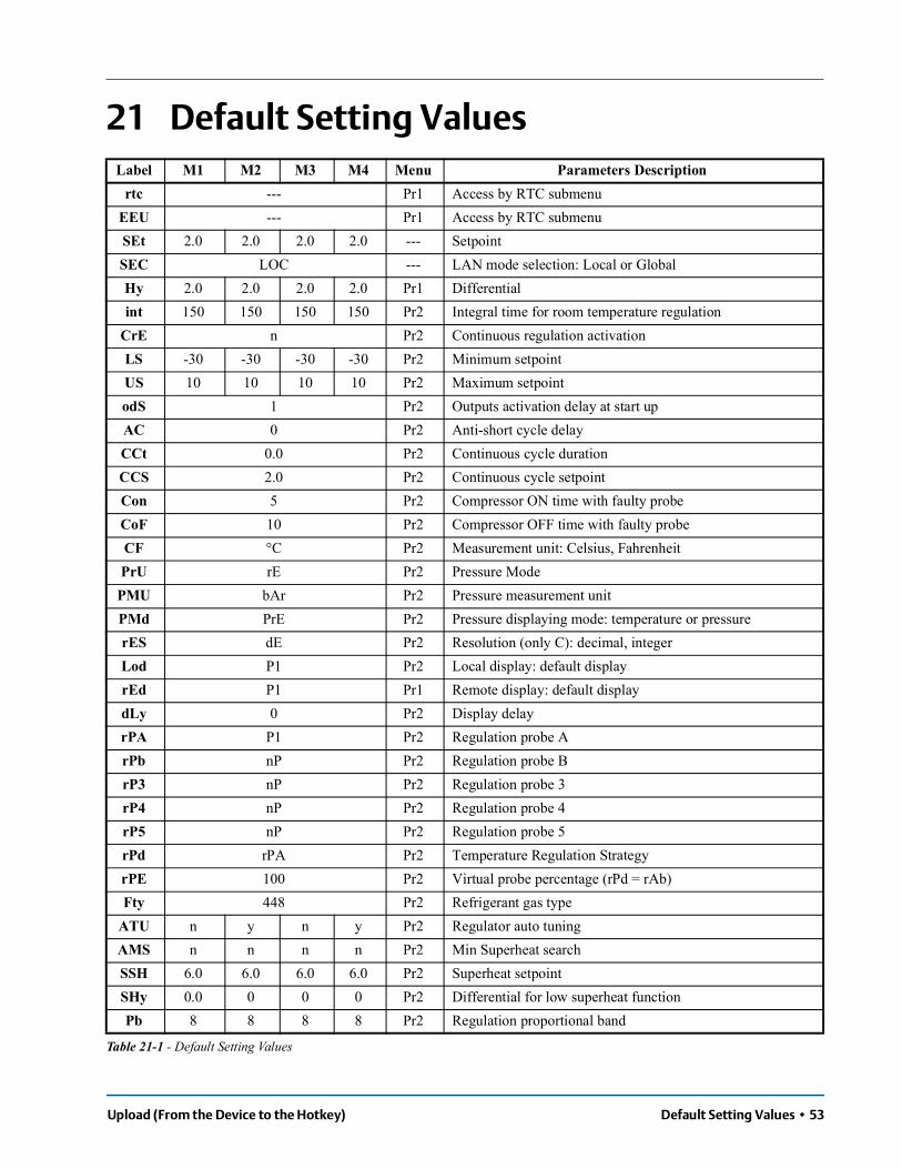
Upload (From the Device to the Hotkey) Default Setting Values • 53
21 Default Setting ValuesLabel M1 M2 M3 M4 Menu Parameters Description
rtc --- Pr1 Access by RTC submenuEEU --- Pr1 Access by RTC submenuSEt 2.0 2.0 2.0 2.0 --- SetpointSEC LOC --- LAN mode selection: Local or GlobalHy 2.0 2.0 2.0 2.0 Pr1 Differentialint 150 150 150 150 Pr2 Integral time for room temperature regulation
CrE n Pr2 Continuous regulation activation LS -30 -30 -30 -30 Pr2 Minimum setpoint US 10 10 10 10 Pr2 Maximum setpoint odS 1 Pr2 Outputs activation delay at start up AC 0 Pr2 Anti-short cycle delay CCt 0.0 Pr2 Continuous cycle duration CCS 2.0 Pr2 Continuous cycle setpoint Con 5 Pr2 Compressor ON time with faulty probe CoF 10 Pr2 Compressor OFF time with faulty probe CF °C Pr2 Measurement unit: Celsius, Fahrenheit PrU rE Pr2 Pressure Mode PMU bAr Pr2 Pressure measurement unit PMd PrE Pr2 Pressure displaying mode: temperature or pressure rES dE Pr2 Resolution (only C): decimal, integer Lod P1 Pr2 Local display: default display rEd P1 Pr1 Remote display: default display dLy 0 Pr2 Display delay rPA P1 Pr2 Regulation probe A rPb nP Pr2 Regulation probe BrP3 nP Pr2 Regulation probe 3 rP4 nP Pr2 Regulation probe 4 rP5 nP Pr2 Regulation probe 5 rPd rPA Pr2 Temperature Regulation Strategy rPE 100 Pr2 Virtual probe percentage (rPd = rAb) Fty 448 Pr2 Refrigerant gas type
ATU n y n y Pr2 Regulator auto tuning AMS n n n n Pr2 Min Superheat search SSH 6.0 6.0 6.0 6.0 Pr2 Superheat setpointSHy 0.0 0 0 0 Pr2 Differential for low superheat function Pb 8 8 8 8 Pr2 Regulation proportional band
Table 21-1 - Default Setting Values

54 • XM678D I&O Manual 026-1224 Rev 1
PbH 0.2 0.2 0.2 0.2 Pr2 Dead band for superheat regulation rS 0 0.0 0.0 0.0 Pr2 Band Offset
inC 220 220 220 220 Pr2 PID integration time dFC 1 1 1 1 Pr2 PID derivation constant time PEd On Pr2 Delay before stopping regulation with probe error PEO 50 Pr2 Probe Error opening percentage SFd 0.3 Pr2 Duration of Soft Start phase SFP 40.0 Pr2 Open percentage for soft start phase
OHG 45.0 45.0 45.0 45.0 Pr2 Open percentage for inversion defrost Pdd 0.4 Pr2 Duration for post defrost phase OPd 50.0 Pr2 Open percentage for post defrost phase LnF 10.0 10.0 10.0 10.0 Pr2 Minimum open percentage for stepper valve MnF 100 100 100 100 Pr2 Maximum open percentage for stepper valve dCL 0 Pr2 Regulation off delay, when the setpoint is reached 2 Fot nu Pr2 Enable for forcing open valve to a fixed value
LPL -0.5 Pr2 Minimum value threshold of pressure for regulation MOP 4.5 4.5 4.5 4.5 Pr2 Maximum value threshold of suction pressure dMP 10 Pr2 Delay for high pressure alarm activation (MOP) LOP -0.5 -0.5 -0.5 -0.5 Pr2 Minimum value threshold of suction pressure dLP 10 Pr2 Delay for low pressure alarm activation (LOP) dML 2.0 2.0 2.0 2.0 Pr2 Opening steps variation during MOP and LOP AAS n Pr2 Low superheat alarm with "XeCO2 function active HSH 60 Pr2 Threshold for maximum superheat alarm LSH 2 Pr2 Threshold for minimum superheat alarm dHS 0.3 Pr2 Delay for high superheat alarm dLS 0.3 Pr2 Delay for low superheat alarm LSA 1.0 Pr2 Subtracting percentage with low superheat alarmFrC 50 Pr2 Additional integration constant for fast recovery
AnP 3 3 3 3 Pr2 Number of average value for converted temperature (pressure)
Ant 1 1 1 1 Pr2 Number of average value for temperature SLb 1 1 1 1 Pr2 Reaction time (interval for valve PID management) tEP nU Pr2 Predefined valve selectiontEU bP Pr2 Kind of valvebdM noM Pr2 Bipolar valve pilot mode: Wave Mode- Normal ModeHFS FUL Pr2 Kind of motor movement
LSt 0 Pr2 Minimum number of steps where the valve can be considered as completely closed
USt 0 Pr2 Maximum number of steps that can be performed
Label M1 M2 M3 M4 Menu Parameters Description
Table 21-1 - Default Setting Values

Upload (From the Device to the Hotkey) Default Setting Values • 55
Est 0 Pr2 Extra steps in closing phase
Sr 10 Pr2 Step rate: The speed to change step. A too high value causes a wrong driving
CPP 0 Pr2 Current per phase during bipolar valve driving
CHd 0 Pr2 Current per phase to maintain the actual position (Holding current)
GtC 0 Pr2 Interval between cycles to reset the valveGtH 10 Pr2 Auto-zero functiondtY 100 Pr2 Pilot dutydPA P2 Pr2 Defrost probe A dPb nP Pr2 Defrost probe B tdF EL EL EL EL Pr2 Kind of defrost: air, resistors, inversion EdF in Pr2 Defrost mode: Clock or interval Srt 150 Pr2 Differential for heater Hyr 2.0 Pr2 Time out for heater (if temp > Srt) tod 255 Pr2 Defrost with two probes d2P n n n n Pr2 Defrost with two probes dtE 8.0 8.0 8.0 8.0 Pr2 First defrost termination temperature dtS 8.0 8.0 8.0 8.0 Pr2 Second defrost termination temperature idF 6 6 6 6 Pr2 Interval between defrosts idE y Pr2 Storage in EEPROM defrost interval ndt 3 3 3 3 Pr2 Minimum Defrost Time
MdF 30 30 30 30 Pr2 Maximum defrost duration dSd 0 Pr2 Delay for defrost on call dFd it Pr2 Visualization during defrost dAd 30 Pr2 Visualization delay for temperature after defrost Fdt 0 0 2 2 Pr2 Dripping time dPo n Pr2 Defrost at power ON dAF 0 Pr2 Delay defrost after freezing Pdt F-C Pr2 Pump down type Pdn 0 Pr2 Pump down duration Ctd 6 6 6 6 Pr2 Differential for defrost start nbd 4.0 4.0 4.0 4.0 Pr2 Minimum Compressor run time before defrost Mdb 16.0 16.0 16.0 16.0 Pr2 Maximum Compressor run time before defrost nct -30 -30 -30 -30 Pr2 Minimum coil temperature to trigger a defrost
FAP P2 Pr2 Fan probe A FnC O-y o-y o-n o-n Pr2 Fan operating mode Fnd 0 0 5 5 Pr2 Fan delay after defrost FCt 10 Pr2 Temperature differential to avoid short cycles of fans
Label M1 M2 M3 M4 Menu Parameters Description
Table 21-1 - Default Setting Values

56 • XM678D I&O Manual 026-1224 Rev 1
FSt 15.0 15.0 2.0 2.0 Pr2 Fan stop temperature FHy 1.0 Pr2 Fan stop hysteresis tFE n Pr2 Fan regulation by temperature in defrost Fod 0 Pr2 Fan activation time after defrost (without compressor) Fon 0 Pr2 Fan ON time FoF 0 Pr2 Fan OFF time trA UAL Pr2 Kind of regulation with PWM output
SOA 0 Pr2 Fixed speed for fanSdP 30.0 Pr2 Default Dewpoint value ASr 1.0 Pr2 Differential for fan / offset for anti-sweat heater PbA 5.0 Pr2 Proportional band for modulating output AMi 0 Pr2 Minimum output for modulating output AMA 100 Pr2 Maximum output for modulating output
AMt 3 Pr2 1:Time with fan at maximum speed 2:The control period for the anti-sweat control
rAL tEr Pr2 Probe for temperature alarm ALC Ab Pr2 Temperature alarm configuration : relative / absolute ALU 10 10 10 10 Pr2 High temperature alarm setting ALL -30 -30 -30 -30 Pr2 Low temperature alarm setting AHy 1.0 Pr2 Differential for temperature alarm ALd 15 15 15 15 Pr2 Temperature alarm delay rA2 nP Pr2 Probe for temperature alarm 2 A2U 150 150 150 150 Pr2 High temperature alarm 2 setting A2L -40 -40 -40 -40 Pr2 Low temperature alarm 2 setting A2H 2 Pr2 Differential for temperature alarm 2 A2d 15 15 15 15 Pr2 Temperature alarm delay 2 dAO 1.0 1.0 1.0 1.0 Pr2 Delay of temperature alarm at start-up EdA 60 Pr2 Alarm delay at the end of defrost dot 30 Pr2 Temperature alarm exclusion after door open Sti nu nu nu nu Pr2 Time for compressor ON before regulation break Std 10 3 3 3 Pr2 Time for compressor OFF for regulation break tbA n Pr2 Silencing alarm relay with buzzer oA5 ALr Pr2 Relay 5 configuration oA6 AUS Pr2 Relay 6 configuration CoM 420 Pr2 Modulating output configuration AOP CL Pr2 Alarm relay polarity iAU n Pr2 Auxiliary output independent from ON/OFF state i1P cL Pr2 Digital input 1 polarity
Label M1 M2 M3 M4 Menu Parameters Description
Table 21-1 - Default Setting Values

Upload (From the Device to the Hotkey) Default Setting Values • 57
i1F dor Pr2 Digital input 1 configuration d1d 15 Pr2 Digital input 1 activation delay i2P cL Pr2 Digital input 2 polarity i2F LiG Pr2 Digital input 2 configuration d2d 5 Pr2 Digital input 2 activation delay i3P cL Pr2 Digital input 3 polarity i3F ES Pr2 Digital input 3 configuration d3d 0 Pr2 Digital input 3 activation delay nPS 15 Pr2 Pressure switch number OdC F-C Pr2 Compressor and fan status when open door rrd 30 Pr2 Outputs restart after door open alarm CbP y Pr2 Clock presence Hur --- Pr1 Current hour Min --- Pr1 Current minutes dAY --- Pr1 Current day Hd1 nu Pr1 First weekly day Hd2 nu Pr1 Second weekly day Hd3 nu Pr1 Third weekly day ILE 0.0 Pr1 Energy saving cycle start during workdays dLE 0.0 Pr1 Energy saving cycle length during workdays ISE 0.0 Pr1 Energy saving cycle start during holidays dSE 0.0 Pr1 Energy saving cycle length during holidays HES 0.0 Pr2 Temperature increasing during Energy Saving Ld1 6.0 Pr1 Workdays First defrost start Ld2 13.0 Pr1 Workdays Second defrost start (minimum as Ld1) Ld3 21.0 Pr1 Workdays Third defrost start (minimum as Ld2) Ld4 nu Pr2 Workdays Fourth defrost start (minimum as Ld3) Ld5 nu Pr2 Workdays Fifth defrost start (minimum as Ld4) Ld6 nu Pr2 Workdays Sixth defrost start (minimum as Ld5) Sd1 6.0 Pr1 Holidays First defrost start Sd2 13.0 Pr1 Holidays Second defrost start Sd3 21.0 Pr1 Holidays Third defrost start Sd4 nu Pr1 Holidays Fourth defrost start Sd5 nu Pr1 Holidays Fifth defrost start Sd6 nu Pr1 Holidays Sixth defrost start HES 0.0 Pr2 Temperature increasing during Energy Saving PEL n Pr2 Energy saving activation when Light switched off LMd y Pr2 Defrost Synchronization
Label M1 M2 M3 M4 Menu Parameters Description
Table 21-1 - Default Setting Values

58 • XM678D I&O Manual 026-1224 Rev 1
dEM y Pr2 Defrost end Synchronization LSP n Pr2 Setpoint Synchronization LdS n Pr2 Display Synchronization (temperature sent via LAN) LOF n Pr2 ON/OFF Synchronization LLi y Pr2 Light Synchronization LAU n Pr2 AUX Synchronization LES n Pr2 Energy Saving Synchronization LSd n Pr2 Remote probe displaying LPP n Pr2 Pressure value sent in LAN LCP n Pr2 P4 probe sent via LAN StM n Pr2 Cooling request from LAN enable compressor relay
ACE n Pr2 Cold Calling in LAN always enabled even if the compressor block
P1C ntc Pr2 P1 configuration OF1 0.0 Pr2 P1 calibration P2C ntc Pr2 P2 configuration OF2 0.0 Pr2 P2 calibration P3C nu Pr2 P3 configuration OF3 0.0 Pr2 P3 calibration P4C nu Pr2 P4 configuration OF4 0.0 Pr2 P4 calibration P5C 420 Pr2 P5 configuration OF5 0.0 Pr2 P5 calibration P6C PtM Pr2 P6 configuration OF6 0.0 Pr2 P6 calibration PA4 0.5 Pr2 Probe value at 4 mA or at 0V (probe P5) P20 11.0 Pr2 Probe value at 20 mA or at 5V (probe P5) LCL y Pr2 Light on during cleaning mode FCL y Pr2 Fan on during cleaning mode MAP 1°M Pr2 Map selection MP1 1°M Pr2 Map selection loaded by digital input Adr 1 Pr1 MODBUS address br 96 Pr2 Baud Rate selection for MODBUS: 9600 or 19200
EMU nu Pr2 Emulation previous version: 2V8, 3V8, 4V2 rEL 5.4 Pr2 Release code firmware (only read) SrL - Pr2 Sub-release firmware (only read) Ptb - Pr2 Map EEPROM ID Pr2 321 Pr1 Password
Label M1 M2 M3 M4 Menu Parameters Description
Table 21-1 - Default Setting Values
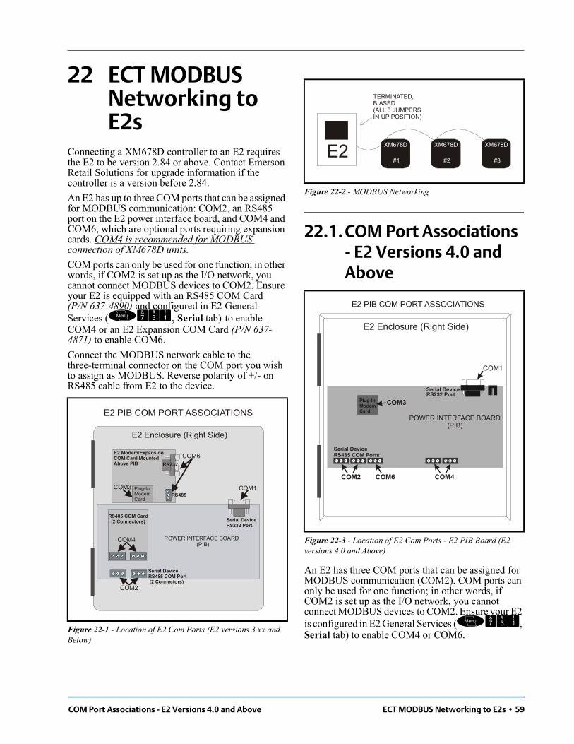
COM Port Associations - E2 Versions 4.0 and Above ECT MODBUS Networking to E2s • 59
22 ECT MODBUS Networking to E2s
Connecting a XM678D controller to an E2 requires the E2 to be version 2.84 or above. Contact Emerson Retail Solutions for upgrade information if the controller is a version before 2.84.An E2 has up to three COM ports that can be assigned for MODBUS communication: COM2, an RS485 port on the E2 power interface board, and COM4 and COM6, which are optional ports requiring expansion cards. COM4 is recommended for MODBUS connection of XM678D units. COM ports can only be used for one function; in other words, if COM2 is set up as the I/O network, you cannot connect MODBUS devices to COM2. Ensure your E2 is equipped with an RS485 COM Card (P/N 637-4890) and configured in E2 General Services (, Serial tab) to enable COM4 or an E2 Expansion COM Card (P/N 637-4871) to enable COM6.Connect the MODBUS network cable to the three-terminal connector on the COM port you wish to assign as MODBUS. Reverse polarity of +/- on RS485 cable from E2 to the device.
22.1. COM Port Associations - E2 Versions 4.0 and Above
An E2 has three COM ports that can be assigned for MODBUS communication (COM2). COM ports can only be used for one function; in other words, if COM2 is set up as the I/O network, you cannot connect MODBUS devices to COM2. Ensure your E2 is configured in E2 General Services (, Serial tab) to enable COM4 or COM6.Figure 22-1 - Location of E2 Com Ports (E2 versions 3.xx and
Below)
E2 PIB COM PORT ASSOCIATIONS
COM1
COM4
COM6
COM2
Serial DeviceRS485 COM Port (2 Connectors)
RS485 COM Card (2 Connectors) Serial Device
RS232 Port
POWER INTERFACE BOARD (PIB)
E2 Modem/Expansion COM Card MountedAbove PIB
Plug-In ModemCard
COM3
E2 Enclosure (Right Side)
RS485
RS232
Figure 22-2 - MODBUS Networking
Figure 22-3 - Location of E2 Com Ports - E2 PIB Board (E2 versions 4.0 and Above)
E2XM678D
#1
TERMINATED,BIASED(ALL 3 JUMPERSIN UP POSITION)
XM678D
#2
XM678D
#3
E2 PIB COM PORT ASSOCIATIONS
COM1
Serial DeviceRS232 Port
POWER INTERFACE BOARD (PIB)
E2 Enclosure (Right Side)
COM2 COM6 COM4
Serial DeviceRS485 COM Ports
Plug-InModemCard
COM3

Connect the MODBUS network cable to the three-terminal connector on the COM port you wish to assign as MODBUS. Reverse polarity of +/- on RS485 cable from E2 to the device
22.2. E2 Setup of Devices22.2.1. Set Up Network PortsBefore setting up a device, the port on the E2 that has the MODBUS cable connected must be set up as a MODBUS port.
1. Log in to the E2 with Level 4 access.
2. Press followed by - General Controller Info.
3. Press + to open the Serial tab of the General Controller Info setup screens:
4. This screen will have a “Connection” field for all COM ports on the E2. Highlight the COM port connection field that will be used for the device, and press - LOOK UP. From the list of network types, select MODBUS.
5. Four fields will become visible underneath the COM port connection field, which pertain to the way the device communicates:
• Baud - Default setting is 19.2K. The baud rate setting should be set to match the baud rate of the XM678D device. (All devices connected to the same COM port should be set to the same baud rate.)
• Data Size - Leave this field at the default value (8).
• Parity - Leave this field at the default value (None).
• Stop Bits - Leave this field at the default value (1).
6. Press to save changes and exit.
22.2.2. Add and Connect the DeviceTo enable communications between E2 and the XM678D units, the devices must be added and addressed in E2.
1. Log in to the E2 with Level 4 access.
2. Press - Connected I/O Boards and Controllers.
3. In the Num Network Ctrls: NetSetup screen, under the ECT tab, enter the number of devices in the Quantity field. (Max shows the maximum number of devices allowed on the network.)
4. Press to return to the Network Setup menu, then select - Network Summary.
5. Locate the units you added to the network list (press and to scroll through the list). If desired, enter a new name for each device in the Name field.
Figure 22-4 - MODBUS Networking
Figure 22-5 - Serial Communications Manager Screen
E2XM678D
#1 #3
TERMINATED,BIASED(ALL 3 JUMPERSIN UP or MOD POSITION)
XM678D XM678D
Figure 22-6 - Num Network Ctrls: NetSetup Screen

Wiring Types ECT MODBUS Networking to E2s • 61
6. By default, each device in the network list has a board number of 0. To set the address and begin communication, choose the device and press . In the list of MODBUS devices, choose the address number corresponding to the XM678D address set up through the front display, and press to select it. A window will open where you can specify the address of the controller. If a network ID has already been selected, its name will be shown next to the network ID in this list. If the network ID you are trying to assign has already been used, you must set the address on this device to a different number that is not being used.
7. Repeat Steps 5 and 6 until each device has a name and address.
8. When finished, press to return to the Net-work Setup menu, then press - Network Summary (Figure 22-7). Locate the devices you set up, and look at each device’s status in the Status field. You will see one of the following messages:
• Online - The device is communicating normally.
• Offline - The device is not communicating, has not been commissioned, is not functional, or is not powered up. Verify the device is powered up, wired correctly, and has the proper network address, baud rate, and parity.
• Unknown - The device is not communicating or has not been commissioned. Verify the device is powered up, wired correctly, and has the proper network address, baud rate, and parity.
• No Port - No port is set up in the E2 Serial Configuration Manager to be a MODBUS port.
• Wrong FW Rev - This message is likely caused by the device having a firmware version older than the minimum revision required by E2 for communication. Replace the device with a new one or a device that has the latest version of firmware on it.
22.3. Wiring TypesEmerson Retail Solutions specifies Belden #8761 shielded twisted pair cables for use as MODBUS wiring (or Belden #82761 and Belden #88761 for plenum installations).
Figure 22-7 - Network Summary Screen
Figure 22-8 - List of MODBUS Devices
Figure 22-9 - Network Summary Screen

62 • XM678D I&O Manual 026-1224 Rev 1
For MODBUS network wiring of XM678D controllers to E2, Belden #8641 (P/N 135-8641) is the recommended wire type to use.If the recommended cable is not available in your area, be sure the wiring meets or exceeds the following specs:
22.4. MODBUS Termination Blocks
Because the XM678D device has no on-board means of termination, use the MODBUS termination block (P/N 535-2711) for termination that can be wired to the end of the cable segment using the three-pin connector. Wire the two signal wires to the outside terminals, and connect the shield to an earth grounded chassis at each end of a network segment, keeping the exposed shield wire length as short as possible (3 inches ideal maximum length).
Shielded? YesConductor Type Twisted PairGauge 18 - 24 AWGCapacitance between signal wires
31 pF/ft or less(9.45 m) or less
Capacitance between signal and shield
59 pF/ft or less(17.98 m) or less
Maximum Length4000 ft/18 to 22 AWG(1219.2 m)2500 ft/24 AWG(762 m)
Nominal Impedance 120W±50W
Figure 22-10 - MODBUS Termination Block (P/N 535-2711)


For Technical Support call 833-409-7505 or email [email protected]
The contents of this publication are presented for informational purposes only and they are not to be construed as warranties or guarantees, express or implied, regarding the products or services described herein or their use or applicability. Emerson reserves the right to modify the designs or specifications of such products at any time without notice. Responsibility for proper selection, use and maintenance of any product remains solely with the purchaser and end-user. ©2022 Emerson is a trademark of Emerson Electric Co.