Optical Burst Transport: A Technology for the WDM Metro Ring Networks
10
JOURNAL OF LIGHTWAVE TECHNOLOGY, VOL. 25, NO. 1,JANUARY 2007 93 Optical Burst Transport: A Technology for the WDM Metro Ring Networks Jaedon Kim, Jinwoo Cho, Saurav Das, David Gutierrez, Mayank Jain, Ching-Fong Su, Member, IEEE, Richard Rabbat, Member, IEEE, Takeo Hamada, Member, IEEE, and Leonid G. Kazovsky, Fellow, IEEE Abstract—We propose a sublambda traffic-grooming scheme on wavelength-division-multiplexing ring networks, named opti- cal burst transport. The network protocol and architecture are designed to support dynamic bandwidth allocation, which is more reasonable for bursty data traffic. To verify our network protocol and architecture, we build a testbed which supports burst-mode transmission. Also, we transmit streaming video over Ethernet as an application. Index Terms—Metropolitan area network (MAN), optical burst transport (OBT), traffic grooming. I. I NTRODUCTION M ETROPOLITAN area networks (MANs) interconnec- ting high-speed backbone and low-speed access net- works mostly rely on synchronous optical network (SONET)/ synchronous digital hierarchy (SDH). Although SONET/SDH combined with wavelength-division-multiplexing (WDM) technology has increased transmission capacity, the efficiency issue regarding data transmission over a circuit-switched network is still present. In addition, recently, access networks have started to provide a large amount of bandwidth by employing advanced LAN technologies, such as digital sub- scriber line (xDSL), cable modems, passive optical network, and wireless access. Consequently, metro networks are ex- pected to suffer a lack of bandwidth to deal with access network traffic in the near future. Although optical network solutions would solve such a metro gap problem, it is not simple for service providers to deploy a new optical MAN solution over a legacy MAN. While high bandwidth and reliable service are in users’ interests, the reduction of OPEX and CAPEX is an important consideration to the service provider. Moreover, noting the large bandwidth change over short periods of the current data traffic, the effective bandwidth provisioning has become a more and more important issue. Over the past few years, there have been tremendous efforts to improve legacy networks regarding the above issues. The generic framing procedure [1] and link capacity adjustment Manuscript received June 30, 2006; revised October 19, 2006. J. Kim, J. Cho, S. Das, D. Gutierrez, M. Jain, and L. G. Kazovsky are with Stanford University, Stanford, CA 94305 USA (e-mail: jdon@ stanford.edu; [email protected]; [email protected]; [email protected]; [email protected]; [email protected]). C.-F. Su and T. Hamada are with Fujitsu Laboratories of America, Sunnyvale, CA 94085 USA (e-mail: [email protected]; richard@ us.fujitsu.com; [email protected]). R. Rabbat is with Google, Inc., Mountain View, CA 94043 USA Color versions of one or more of the figures in this paper are available online at http://[email protected]. Digital Object Identifier 10.1109/JLT.2006.888483 scheme (LCAS) [2] have been developed to enhance SONET with data-friendly features. Also, virtual concatenation (VCAT) [3] can increase the network utilization by setting the connec- tion bandwidth at fine granularities. Next-generation SONET will allow dynamic allocation of link capacity for optimization of the overall throughput. Another approach has been developed to adapt Ethernet to MAN, which is supported by the IEEE Resilient Packet Ring (RPR) Working Group (IEEE 802.17). Compared to the legacy SONET, RPR increases bandwidth efficiency introducing a spatial reuse and a differentiated bandwidth provisioning based on class of frame. However, current point to point connected networks require every node to process large amount of transit traffic which increases complexity, cost, size, and power requirements. In addition, to support the ever-growing traffic volume in the metro area, networks inherently supporting WDM will become necessary in the near future. In such case, network equipment upgrade costs will increase stepwise in current point to point connected network, because all nodes should have the same number of transceivers. Therefore, a protocol supporting more flexible resource management is also necessary. Optical packet switching (OPS) [4]–[6] was developed to address such problems. With no optical-electronic conversion and high-speed electronics, these switches could theoretically accommodate a very large amount of traffic and switch data at a very small granularity. The motivation for optical burst switching (OBS) [7], [8] is to alleviate some of the optical problems of OPS as well as to do less optical processing. The objective of OBS is to assemble large bursts of data and switch them optically by looking at the burst header/label. That label can be sent ahead of the burst in order to allow enough time for the switching fabric to reconfigure. It can also be sent out of band on a different control channel and processed electronically. Other solutions have been proposed where IP routers or layer-2 switches are used to groom traffic in optical networks while optical links (e.g., point-to-point WDM transmission systems) interconnect high-speed routers. However, replacing transport network equipment (e.g., SONET add drop multiplexer) with IP routers is not a very scalable solution because each individual IP packet needs to be processed. On the other hand, simply collapsing the layer be- tween IP routers and WDM networks, as advocated by OPS and OBS technologies, is not necessarily practical today because of immature optical components such as optical buffers and large port-count nanoswitches. Nevertheless, we do need a new optical transport architecture that is more adaptive and flexible 0733-8724/$25.00 © 2007 IEEE
-
Upload
independent -
Category
Documents
-
view
0 -
download
0
Transcript of Optical Burst Transport: A Technology for the WDM Metro Ring Networks
JOURNAL OF LIGHTWAVE TECHNOLOGY, VOL. 25, NO. 1, JANUARY 2007 93
Optical Burst Transport: A Technology for theWDM Metro Ring Networks
Jaedon Kim, Jinwoo Cho, Saurav Das, David Gutierrez, Mayank Jain, Ching-Fong Su, Member, IEEE,Richard Rabbat, Member, IEEE, Takeo Hamada, Member, IEEE, and Leonid G. Kazovsky, Fellow, IEEE
Abstract—We propose a sublambda traffic-grooming schemeon wavelength-division-multiplexing ring networks, named opti-cal burst transport. The network protocol and architecture aredesigned to support dynamic bandwidth allocation, which is morereasonable for bursty data traffic. To verify our network protocoland architecture, we build a testbed which supports burst-modetransmission. Also, we transmit streaming video over Ethernet asan application.
Index Terms—Metropolitan area network (MAN), optical bursttransport (OBT), traffic grooming.
I. INTRODUCTION
M ETROPOLITAN area networks (MANs) interconnec-ting high-speed backbone and low-speed access net-
works mostly rely on synchronous optical network (SONET)/synchronous digital hierarchy (SDH). Although SONET/SDHcombined with wavelength-division-multiplexing (WDM)technology has increased transmission capacity, the efficiencyissue regarding data transmission over a circuit-switchednetwork is still present. In addition, recently, access networkshave started to provide a large amount of bandwidth byemploying advanced LAN technologies, such as digital sub-scriber line (xDSL), cable modems, passive optical network,and wireless access. Consequently, metro networks are ex-pected to suffer a lack of bandwidth to deal with access networktraffic in the near future. Although optical network solutionswould solve such a metro gap problem, it is not simple forservice providers to deploy a new optical MAN solution overa legacy MAN. While high bandwidth and reliable serviceare in users’ interests, the reduction of OPEX and CAPEX isan important consideration to the service provider. Moreover,noting the large bandwidth change over short periods of thecurrent data traffic, the effective bandwidth provisioning hasbecome a more and more important issue.
Over the past few years, there have been tremendous effortsto improve legacy networks regarding the above issues. Thegeneric framing procedure [1] and link capacity adjustment
Manuscript received June 30, 2006; revised October 19, 2006.J. Kim, J. Cho, S. Das, D. Gutierrez, M. Jain, and L. G. Kazovsky
are with Stanford University, Stanford, CA 94305 USA (e-mail: [email protected]; [email protected]; [email protected]; [email protected];[email protected]; [email protected]).
C.-F. Su and T. Hamada are with Fujitsu Laboratories of America,Sunnyvale, CA 94085 USA (e-mail: [email protected]; [email protected]; [email protected]).
R. Rabbat is with Google, Inc., Mountain View, CA 94043 USAColor versions of one or more of the figures in this paper are available online
at http://[email protected] Object Identifier 10.1109/JLT.2006.888483
scheme (LCAS) [2] have been developed to enhance SONETwith data-friendly features. Also, virtual concatenation (VCAT)[3] can increase the network utilization by setting the connec-tion bandwidth at fine granularities. Next-generation SONETwill allow dynamic allocation of link capacity for optimizationof the overall throughput.
Another approach has been developed to adapt Ethernet toMAN, which is supported by the IEEE Resilient Packet Ring(RPR) Working Group (IEEE 802.17). Compared to the legacySONET, RPR increases bandwidth efficiency introducing aspatial reuse and a differentiated bandwidth provisioning basedon class of frame.
However, current point to point connected networks requireevery node to process large amount of transit traffic whichincreases complexity, cost, size, and power requirements. Inaddition, to support the ever-growing traffic volume in themetro area, networks inherently supporting WDM will becomenecessary in the near future. In such case, network equipmentupgrade costs will increase stepwise in current point to pointconnected network, because all nodes should have the samenumber of transceivers. Therefore, a protocol supporting moreflexible resource management is also necessary.
Optical packet switching (OPS) [4]–[6] was developed toaddress such problems. With no optical-electronic conversionand high-speed electronics, these switches could theoreticallyaccommodate a very large amount of traffic and switch dataat a very small granularity. The motivation for optical burstswitching (OBS) [7], [8] is to alleviate some of the opticalproblems of OPS as well as to do less optical processing.The objective of OBS is to assemble large bursts of data andswitch them optically by looking at the burst header/label.That label can be sent ahead of the burst in order to allowenough time for the switching fabric to reconfigure. It canalso be sent out of band on a different control channel andprocessed electronically. Other solutions have been proposedwhere IP routers or layer-2 switches are used to groom traffic inoptical networks while optical links (e.g., point-to-point WDMtransmission systems) interconnect high-speed routers.
However, replacing transport network equipment (e.g.,SONET add drop multiplexer) with IP routers is not a veryscalable solution because each individual IP packet needs to beprocessed. On the other hand, simply collapsing the layer be-tween IP routers and WDM networks, as advocated by OPS andOBS technologies, is not necessarily practical today becauseof immature optical components such as optical buffers andlarge port-count nanoswitches. Nevertheless, we do need a newoptical transport architecture that is more adaptive and flexible
0733-8724/$25.00 © 2007 IEEE
94 JOURNAL OF LIGHTWAVE TECHNOLOGY, VOL. 25, NO. 1, JANUARY 2007
Fig. 1. OBT node architecture.
in order to meet the traffic requirement of current and futureInternet applications. Hence, we propose optical burst transport(OBT) [9] to bridge the architectural mismatch between acircuit-based physical transport and the carried bursty packetstreams. OBT is based on burst-mode transmission betweensenders and receivers on a WDM ring topology, and does notrequire complex electronic processing.
This paper is organized as follows. Section II describes thenew OBT architecture and compares OBT with other networkarchitectures. Section III discusses the testbed implementationto verify OBT network. The extension of OBT combined withEthernet is investigated in Section IV. Section V concludesthis paper.
II. OBT NETWORK ARCHITECTURE AND PROTOCOL
A. Network Architecture and Basic Operation
In order to accommodate bursty data traffic at the opticaltransport layer, we propose a new network architecture thatsupports burst-mode transmission via fast optical switches onWDM networks. As shown in Fig. 1, the burst-mode transmis-sion is made possible by swift reconfiguration of short-termlight paths through the optical switch.
The network topology is based on WDM ring, where onecontrol channel and multiple data channels occupy dedicatedwavelengths. Each network node processes incoming controlsignals on the control channel and reacts accordingly. Con-trol signals include 1) token, 2) control header (CH), and3) network-management messages. When a token arrives ata node, the node holds it and utilizes the corresponding datachannel to transmit data packets only if it has enough data tosend. If the amount of data is not enough, the node passesthe token to next node. In each node, packets waiting fortransmission are stored in several virtual output queues (VOQs)associated with their destination nodes on the ring. When thenode has enough data to transmit, the scheduler within thenode allocates affordable transmission session for each VOQbased on the length of VOQs. After that, chunks of packets
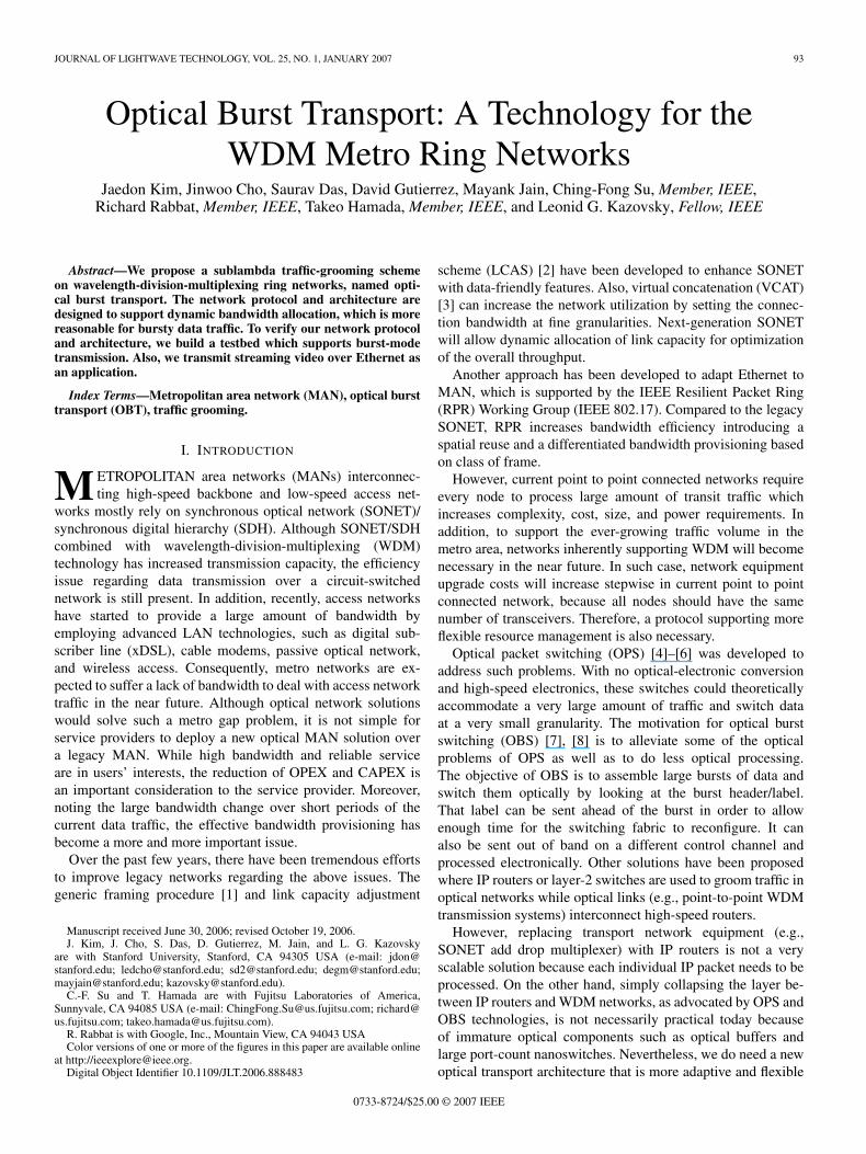
Fig. 2. Traffic on the control channel and data channel at the source node.
are shifted from each VOQ to a transmission queue to form aburst. Therefore, a single burst would have several subburstsfor different destinations and all packets in a subburst havethe same destination. After building a burst, the node sendsa CH to a destination followed by the subburst. BetweenCH and subburst, it is required to put a constant offset timecorresponding to the time to configure the light path and processthe control packet. Since control and data channels are separate,we can send a CH to another destination in the middle ofdata transmission for one destination; this saves bandwidth fordata transmission. A timing diagram of CHs and subbursts isillustrated in Fig. 2. Since the burst size is a parameter that canbe properly tuned, the OBT protocol allows flexibility betweenthe two extremes of data-oriented or circuit-oriented servicesfor optimal use of network resources.
The traffic load in the network is defined as [10]
ρ =NR
Cλ(1)
where N corresponds to the number of nodes on the ring, Rthe arrival data rate of the traffic to be added onto the OBTring, C the capacity on each WDM channel, and λ the numberof wavelengths. In the case of an ideal burst transport system,the network throughput is proportional to the incoming trafficrate, that is
Throughput = R =Cλ
Nρ (2)
which shows that the network throughput is independent of theburst sizes. Burst size, however, provides an upper bound on

KIM et al.: OPTICAL BURST TRANSPORT: TECHNOLOGY FOR THE WDM METRO RING NETWORKS 95
utilization Umax. From (2), ρ can be interpreted as the ratio oftotal incoming traffic to the network to the maximum affordabletransmission capacity of the network. When U ≤ Umax, ρ ≈ Uin the stabilized network because the blocking probability is farless than 1. Let the token round trip time be D, and the bursttransmission time be b. To achieve the maximum utilization,every node always has to be in the ready-to-transmit state.Then, on a single data channel, the token arrives at the specificnode every R = D + bN second, and each node transmits datafor b seconds at every R second. Since the number of node isN , the maximum utilization of the network is
Umax =size of transmitted burst
maximum round trip time× N =
bN
D + bN. (3)
Equation (3) indicates that the maximum utilization becomes100 percentile as b goes to infinite.
In order to manage multiple WDM data channel, multipletokens can propagate on the same control channel to carryaccess grants for respective data channels (wavelengths). Com-bined with tunable transceivers, multiple tokens can managethe WDM network without stepwise increasing the number oftransceivers.
B. Spatial Reuse
Since only one OBT node can access a data channel at atime through a dedicated token, the network does not havecollisions on a single data channel. However, as in the otherscheduled media-access control (MAC) protocols, the networkresource cannot be fully utilized and efficiency is low. For moreresource utilization, OBT offers a spatial reuse mechanism. Aswe discussed in Section II-A, in the OBT network, destinationstripping enables a data burst to be terminated at each desti-nation. Scrutinizing the signal channel unidirectional path onthe OBT network, when the token is held by a source nodefor transmission to the destination node, the data path fromthe source to the destination is occupied, while the data pathfrom the destination to the source is empty and could be usedfor another transmission. During the time when a destinationnode is receiving the data, it is also granted an opportunityto transmit its own data. Upon receiving a CH destined toit, the node knows the time duration for transmitting as wellas receiving its data at the same time. Therefore, destinationnodes are allowed to initiate a secondary transmission withouta token to make full use of the available capacity. The size ofthe secondary transmission is less than the reception time ofthe subburst because the CH process time would be includedin the secondary transmission time slot. Since the secondarytransmission uses the timeslot informed by the CH, the size ofsecondary transmission could have different value every time.Therefore, burst aggregation for the secondary traffic does notfollow the burst length-based algorithm but has a maximumallowed time slot. Note that during the secondary transmission,the destination of the secondary transmission may also createanother transmission for better transmission performance.
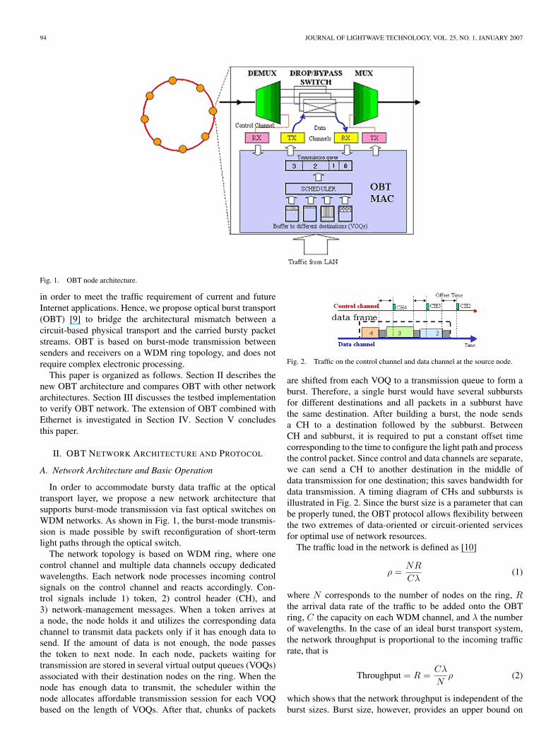
Fig. 3 shows the benefit of spatial reuse. We use two sim-ulation models with or without spatial reuse scheme. In each
case, a WDM ring network consisting of five nodes is analyzed,with a circumference of 200 km. Each node has the same fixedburst size of 200 kB. The data rate is 1.25 Gb/s per wavelengthon data channel and 625 Mb/s on the control channel. Forsimplicity, we use a single data channel, but, from (2), it iseasily expected that network throughput will linearly increasewith the number of WDM data channel. For each traffic load,we run the simulation ten times and take the average value.
As shown in Fig. 3(a), the throughput for the OBT networkwithout spatial reuse is close to the theoretical maximum value,because a deviation for all simulation results are not significant.From the simulation condition
N =5
b =200 × 8 × 103/(1.25 × 109) = 1.28 × 10⁻³
D =200 × 103/(2 × 108) = 1 × 10⁻³.
Therefore, from (3)
Umax = 0.864
and
Maximum throughput = R(ρ = Umax) = 216.2 Mb/s.
There is a small deviation due to the finite token propagationtime between adjacent nodes. On the other hand, the OBT withspatial reuse shows considerable improvement by increasingchannel capacity from C to 2C. In the analysis, the delaymeasurement consists of the transmission delay, propagationdelay and queuing delay of every packet. In Fig. 3(b), thedelay remains low when the traffic load is lower than Umax
and exhibits a sharp increase when the traffic load close toUmax. Another observation about latency is that latency hasbecome large at very low traffic load, and decreases as the trafficload increases. This is because we set the maximum length toassemble a burst. The choice of burst assembly algorithm forOBT, however, is flexible. To compensate the large latency atlow traffic load, we can also apply hybrid time and length-based algorithm [12] or dynamic burst assembly algorithm [13].Due to the effectively enlarged channel capacity, the averagedelay performance at the node significantly improves. From (1),we can also expect this performance improvement. Since thespatial reuse makes channel capacity from C to 2C, effectively,ρ axis of Fig. 3 expands twofolds. Therefore, the latency withthe spatial reuse can keep a low value even at ρ = 1 because,ρ is equivalent to 0.5 without the spatial reuse.
C. Network Resilience
The network topology of OBT is a unidirectional ring. Toensure that the time required enabling protection in the ringis minimized, while keeping the unidirectional approach tomake possible a low cost and simple implementation at thenode, we chose 1 + 1 optical layer protection. Since theprotection scheme can be categorized as optical unidirectionalline switched ring (OULSR), it shares the characteristics ofOULSR [14]. On top of the optical layer protection, we canadd more procedures to increase network resilience. In typical
96 JOURNAL OF LIGHTWAVE TECHNOLOGY, VOL. 25, NO. 1, JANUARY 2007
Fig. 3. Comparison of network performance with or without spatial reuse. (a) Throughput. (b) Delay.
OULSR protection, we could not prevent data loss during linkfailure. In OBT, however, we can reduce the loss by addingadditional procedure to the protection.
In OBT with optical link protection, burst will be lost untilthe token passes through the failed link because not all nodesknow the link failure. After the token loss, no node can transmitits burst until the link is recovered and the token is regenerated.The token is managed by a designated master node, which takea charge of the following.
1) Generate token upon network start.2) Regenerate token when the token is lost.
Therefore, token will be regenerated by a master node everymaximum token round trip time, which can cause data loss dur-ing the link failure. To reduce data loss as well as increase band-width efficiency, we have developed the following procedure.
1) If the node detects the loss of control channel signal, itbecomes the node of detection (NOD).
2) The NOD assumes the role of the master node and startstoken timeout timers for all data channel tokens.
3) The NOD sends out the fault message on the controlchannel and initiates the switch of its incoming path tothe protection fiber.

KIM et al.: OPTICAL BURST TRANSPORT: TECHNOLOGY FOR THE WDM METRO RING NETWORKS 97
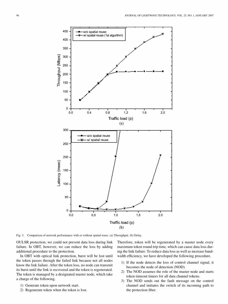
Fig. 4. Delivered and lost data frame with and without MAC control.
4) The fault message informs every node of the existence ofthe fault as the control channel is processed hop by hopdown to the node of failure (NOF).
5) As nodes become “fault aware,” they avoid sendingany secondary transmission until they receive FaultOKmessage.
6) When the old master node becomes “fault aware” itimmediately stops all its token timeout timers and ceasesto be the master node.
7) When the old master node is the NOD, in which case itcontinues to be the master and does not stop its tokentimeout timers.
8) Upon timeout of the tokens at the NOD, the NOD regen-erates intelligent tokens that require nodes to exclude allnodes beyond the NOF from their destination set.
9) Ultimately when the NOF sends out the FaultOK mes-sage, again every node becomes aware that the fault hasbeen bypassed and they resume sending primary andsecondary transmissions to all destinations.
10) Finally, the NOD remains as the master node.
The same simulation model as in Section II-B with two differentprotection mechanisms has been used to observe the effect oflink failure. For each simulation, we set master node as node 0,traffic load as 0.8, and run the simulation with different node offailure. With respect to protection time, we consider two mainfactors—protection switch time and ring latency for the NOFto be informed of the fault. The protection switching time isconservatively assumed to be 10 ms and the ring latency forthe above defined ring circumference is 1 ms. Thus, the totalprotection time is a little over 12 m. For a single node failure, werun ten times and observe lost and delivered bursts for the entirenetwork and take the average value. As can be seen in Fig. 4,with only optical layer protection, the amount of delivered dataand lost data becomes larger, as a broken link is further fromthe master node. This is because token can exist longer in thenetwork, which gives nodes a higher chance to transmit itsown burst.
The result becomes different when we add our protectionalgorithm on the optical layer protection. First, data loss is
TABLE ICOMPARISON OF NEXT-GENERATION SONET, RPR, AND OBT
suppressed for every different location of failure. At the sametime, data delivery is also improved for all the location offailure. After adding additional protection algorithm, we canremove fault location dependence because master node willshift to NOD whenever the link is broken.
D. Comparison With Other Network Architecture
It is instructive to compare OBT with the current technolo-gies, next-generation SONET with VCAT and LCAS support,and RPR, as listed in Table I. All these designs are basedon the ring topology, and are suitable for transmission ofdata-dominant traffic. However, the logical connection at theelectrical layer shows a different connection topology. Logicalmesh over physical ring (LMPR) is a logical mesh topologyrealized over a physical ring.
We consider one-way average hop distance in order to com-pare both topologies. In physical-ring network, when averagehop distance increase, every transmitted data will get throughmore intermediate nodes. That is, each node will receive moretransit traffic, which is not destined to it. As a result, a nodewill waste more processing time and power on load destinedto other nodes, when average hop distance increases. Assumingthat there are N nodes on the ring, any one node on the ringhas N − 1 adjacent nodes, and any node on the ring can reachany other node in a single hop. Logical ring over physicalring is another extreme, whose adjacencies are only limited toimmediate neighbors. The average hop distance between nodeson the ring is N/2. Next-generation SONET and OBT are bothLMPR. As a result, next-generation SONET and OBT do notneed to backlog transmit traffic because of dealing with tran-sit traffic. Next-generation SONET, however, still relies on aconventional management system and signaling protocols suchas generalized multiprotocol label switching to realize dynamicbandwidth provisioning, which typically takes a few secondsup to a few minutes. OBT, on the other hand, uses tokens forcontrolling optical-burst, which enables submillisecond pro-visioning time. All these schemes support traffic grooming.Next-generation SONET uses SONET hierarchy so that thegranularity of bandwidth is a multiple of virtual tributary groupsfrom VT1.5 to STS-3c. RPR is designed as to handle Ethernetframe as well as SONET frames. OBT is also able to aggregateEthernet packets, which will be shown in Section IV. Moreover,the OBT protocol is compatible with tunable transceivers forWDM systems, while next-generation SONET and RPR needadditional transceivers for underlying WDM channels.

98 JOURNAL OF LIGHTWAVE TECHNOLOGY, VOL. 25, NO. 1, JANUARY 2007
Fig. 5. Testbed configuration.
III. TESTBED IMPLEMENTATION
A prototype experimental testbed is constructed forinvestigation as illustrated in Fig. 5. The testbed consists ofthree nodes and uses two International TelecommunicationUnion Telecommunication Standardization Sector (ITU-T)dense WDM wavelengths occupied by the control and datachannel. Line rates are 2.5 and 1.25 Gb/s for data and controlchannel each. An Field Programmable Gate Array (FPGA)(Vertex II-pro, Xilinx) and its evaluation boards serve asprocessors in each node to implement the MAC protocol andnecessary data processing. Each node needs the transceivers tosupport burst-mode transmission. For the transmitters, we havesome alternative choice. Besides the optical switch and laserdiode, which are applied to our testbed, we can also think ofother combinations such as tunable laser and arrayed waveguidegratings or burst-mode laser driver and laser diode.
On the other hand, the burst-mode receiver is the morechallenging of the two aspects. As described in Fig. 6, it iscommon for high-passing devices to have a low-frequencycancellation part which consists of a differential amplifier andlow pass filter feed back loop. Such a high-passing device cansuffer from the baseline wandering problem due to consecutiveidentical digits (CIDs) [11]. In burst-mode transmission, thereexists a lot of CIDs because no signal can be transmitted duringidle time. Consequently, it is very likely for the conventionalreceiver to suffer from baseline wandering problem. Therefore,the time constant of the feedback loop, which can be definedby R, C1, and C2 in Fig. 6, should be lowered to mitigatethe problem. Care should be taken to lower the time constant,because, if we overreduce the time constant, the signal powerwould be reduced by increasing the cutoff frequency of the lowpass filter, which seriously degrades the signal to noise ratio.
Another challenge in the design of the burst-mode receiveris burst-mode clock recovery. Since burst-mode clock recoverytechnology is not so mature to support 2.5-Gb/s system, weuse conventional phase-locked loops integrated in the FPGA,which guarantees to recover clock signal within 1 µs. Contraryto packet switching, burst switching has coarse granularity forits time frame due to packet aggregation. In our experiments,we use 100 µs (31.25 kB at 2.5 Gb/s) or 48 µs (15 kB at2.5 Gb/s) as sizes of burst so that the overhead resulting fromthe clock recovery time is less than 2%. Considering Ethernetpacket sizes distributed between 64 and 1500 B, our burst sizeis moderate in terms of packet aggregation. On the flip side,noticing the maximum frame size of generic frame protocol is
65 kB, our burst size is not big enough as to incur a significanttransmission delay.
Protocol operation is monitored using logic analyzer as inFig. 7(a). In Fig. 7(a), the source transmits 48-µs data burst tofirst destination and second destination. While first destinationreceives data for 32 µs, second destination receives data for16 µs after a corresponding transmission and propagation delay.Propagation delay from source to first destination is 125 and200 µs from source to second destination. One of the nodes inthe ring network, designated as the master node, is responsiblefor initializing tokens upon the system power-up. In addition, atimer in this node estimates the token round-trip time plus hold-ing time by other nodes and triggers a regeneration process ifit does not receive the token back within that specific period oftime. The data add and drop is monitored as in Fig. 7(b). For thisexperiment, we use a smaller frame size because the guard timeis too small to be shown in the scale of 50 µs/div. As we dis-cussed in Section II-A, the offset time consists of the switchingtime of the optical switch and the CH processing time. It takesfive clocks for each node to process a CH, which correspondsto 80 ns. As can be seen in Fig. 7(b), switching time of opticalswitch is 260 ns. Hence, the overall offset time is 340 ns.
The bit-error-rate (BER) test was done to verify the datalink performance. As described in Fig. 8(a), the transmitter isdirectly modulated by a pattern generator which generates acontinuous pseudorandom bit sequence 223 − 1 at 2.5 Gb/s.Whenever a token arrives at node 1, it sends the CH andchanges the switch to connect between transmitter and ring.When node 2 receives the CH, it changes the switch toreceive data for a specific duration, and then switches it back.During the time node 2 receives data, node 2 also enablesa gating signal for the bit error detector so that the errordetector counts bit errors. In the Fig. 8(b), the circle indicatestransmission without switching, which becomes continuousmode transmission. For the burst-mode transmission, we senddata for 100 µs to the first destination and 50 µs to the seconddestination. BER is measured at the first destination. Comparedto continuous mode transmission, burst-mode transmissionshows about 4.5-dB power gain at the same BER. However,noting the power meter takes the time average to calculatethe received power, despite the fact that burst and continuousmodes use the same power at the transmitter, the power metershows a smaller value for the burst-mode transmission, becausethe power meter receives nothing during the idle time. In ourexperiment, the round trip time for a token is 475 µs. Thetime, during which data is transmitted to the first destination,is 100 µs. Therefore, the power meter would receive thereal signal only for 100 µs every 475 µs and during the other375 µs receive nothing. As a result, the power in the burst-modetransmission is measured to be almost 0.315(= 100/475) timesless than that of the continuous mode transmission, whichcorresponds to 5.016 dB. After the power compensation, whichis indicated by the dotted line, we can see that continuousmode transmission and burst-mode transmission use almost thesame peak power. The discrepancy may come from the timingmismatch between the gating signal and real received data.However, the result indicates that we can save transmissionenergy using the burst-mode transmission.

KIM et al.: OPTICAL BURST TRANSPORT: TECHNOLOGY FOR THE WDM METRO RING NETWORKS 99
Fig. 6. Optical receiver.
Fig. 7. Testbed configuration. (a) Control signals shown on the logic analyzer.Signal receiving, sending, and bypassing are represented by “r,” “s,” and “b,”respectively. (b) Data add/drop monitored at the first destination.
IV. ETHERNET WITH OBT
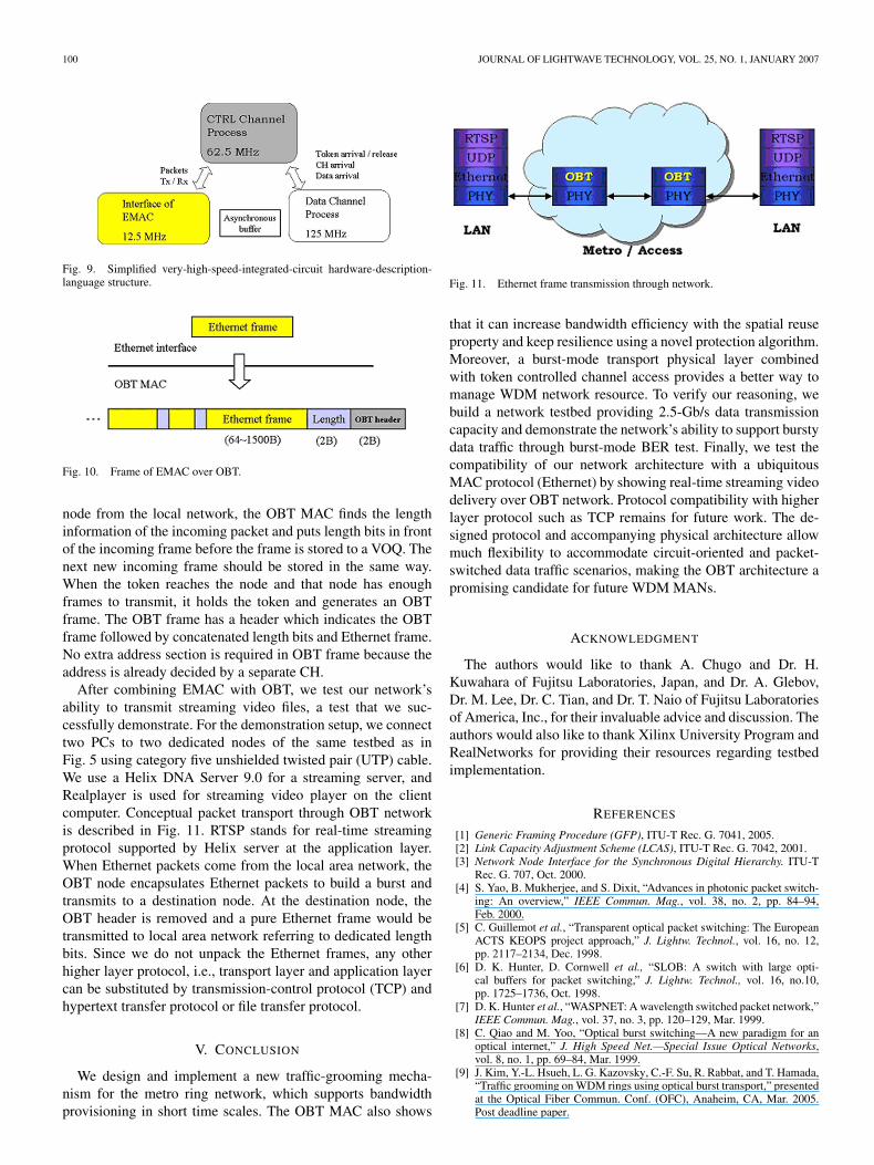
So far, we assumed incoming traffic from the access networkis already in the OBT node. However, it is more reliable to showthe capability to deal with incoming packets from the local andaccess network. Ethernet packets are a proper encapsulationfor incoming data traffic since it has become the most popularMAC protocol in local and access area networks. Therefore, itis necessary to consider how to handle Ethernet packets in theOBT network. To investigate the compatibility with EthernetMAC (EMAC), we attempt to combine Ethernet and OBTMAC protocol. In the system clock point of view, 100-Mb/sEMAC uses 12.5 MHz, while OBT uses 62.5 and 125 MHz to
Fig. 8. BER test (a) experiment setup (b) result.
run the control channel process and data channel process. Asdescribed in Fig. 9, the OBT control channel process takes arole of combining EMAC and OBT by communicating withthe OBT data channel process and interface of EMAC. Thecommunication between control and data process is just toindicate a packet arrival or departure. However, it requiresa more sophisticated process for the communication betweenOBT control channel and interface of EMAC because it needsnot only to indicate packet arrival and departure but also tostore, process, and encapsulate incoming Ethernet frames.
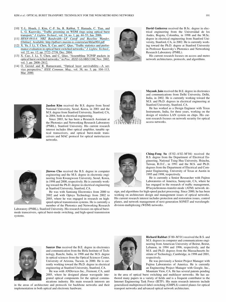
Ethernet frames can be aggregated at the OBT node asshown in Fig. 10. When an Ethernet frame arrives at the OBT
100 JOURNAL OF LIGHTWAVE TECHNOLOGY, VOL. 25, NO. 1, JANUARY 2007
Fig. 9. Simplified very-high-speed-integrated-circuit hardware-description-language structure.
Fig. 10. Frame of EMAC over OBT.
node from the local network, the OBT MAC finds the lengthinformation of the incoming packet and puts length bits in frontof the incoming frame before the frame is stored to a VOQ. Thenext new incoming frame should be stored in the same way.When the token reaches the node and that node has enoughframes to transmit, it holds the token and generates an OBTframe. The OBT frame has a header which indicates the OBTframe followed by concatenated length bits and Ethernet frame.No extra address section is required in OBT frame because theaddress is already decided by a separate CH.
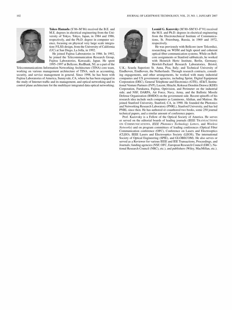
After combining EMAC with OBT, we test our network’sability to transmit streaming video files, a test that we suc-cessfully demonstrate. For the demonstration setup, we connecttwo PCs to two dedicated nodes of the same testbed as inFig. 5 using category five unshielded twisted pair (UTP) cable.We use a Helix DNA Server 9.0 for a streaming server, andRealplayer is used for streaming video player on the clientcomputer. Conceptual packet transport through OBT networkis described in Fig. 11. RTSP stands for real-time streamingprotocol supported by Helix server at the application layer.When Ethernet packets come from the local area network, theOBT node encapsulates Ethernet packets to build a burst andtransmits to a destination node. At the destination node, theOBT header is removed and a pure Ethernet frame would betransmitted to local area network referring to dedicated lengthbits. Since we do not unpack the Ethernet frames, any otherhigher layer protocol, i.e., transport layer and application layercan be substituted by transmission-control protocol (TCP) andhypertext transfer protocol or file transfer protocol.
V. CONCLUSION
We design and implement a new traffic-grooming mecha-nism for the metro ring network, which supports bandwidthprovisioning in short time scales. The OBT MAC also shows
Fig. 11. Ethernet frame transmission through network.
that it can increase bandwidth efficiency with the spatial reuseproperty and keep resilience using a novel protection algorithm.Moreover, a burst-mode transport physical layer combinedwith token controlled channel access provides a better way tomanage WDM network resource. To verify our reasoning, webuild a network testbed providing 2.5-Gb/s data transmissioncapacity and demonstrate the network’s ability to support burstydata traffic through burst-mode BER test. Finally, we test thecompatibility of our network architecture with a ubiquitousMAC protocol (Ethernet) by showing real-time streaming videodelivery over OBT network. Protocol compatibility with higherlayer protocol such as TCP remains for future work. The de-signed protocol and accompanying physical architecture allowmuch flexibility to accommodate circuit-oriented and packet-switched data traffic scenarios, making the OBT architecture apromising candidate for future WDM MANs.
ACKNOWLEDGMENT
The authors would like to thank A. Chugo and Dr. H.Kuwahara of Fujitsu Laboratories, Japan, and Dr. A. Glebov,Dr. M. Lee, Dr. C. Tian, and Dr. T. Naio of Fujitsu Laboratoriesof America, Inc., for their invaluable advice and discussion. Theauthors would also like to thank Xilinx University Program andRealNetworks for providing their resources regarding testbedimplementation.
REFERENCES
[1] Generic Framing Procedure (GFP), ITU-T Rec. G. 7041, 2005.[2] Link Capacity Adjustment Scheme (LCAS), ITU-T Rec. G. 7042, 2001.[3] Network Node Interface for the Synchronous Digital Hierarchy. ITU-T
Rec. G. 707, Oct. 2000.[4] S. Yao, B. Mukherjee, and S. Dixit, “Advances in photonic packet switch-
ing: An overview,” IEEE Commun. Mag., vol. 38, no. 2, pp. 84–94,Feb. 2000.
[5] C. Guillemot et al., “Transparent optical packet switching: The EuropeanACTS KEOPS project approach,” J. Lightw. Technol., vol. 16, no. 12,pp. 2117–2134, Dec. 1998.
[6] D. K. Hunter, D. Cornwell et al., “SLOB: A switch with large opti-cal buffers for packet switching,” J. Lightw. Technol., vol. 16, no.10,pp. 1725–1736, Oct. 1998.
[7] D. K. Hunter et al., “WASPNET: A wavelength switched packet network,”IEEE Commun. Mag., vol. 37, no. 3, pp. 120–129, Mar. 1999.
[8] C. Qiao and M. Yoo, “Optical burst switching—A new paradigm for anoptical internet,” J. High Speed Net.—Special Issue Optical Networks,vol. 8, no. 1, pp. 69–84, Mar. 1999.
[9] J. Kim, Y.-L. Hsueh, L. G. Kazovsky, C.-F. Su, R. Rabbat, and T. Hamada,“Traffic grooming on WDM rings using optical burst transport,” presentedat the Optical Fiber Commun. Conf. (OFC), Anaheim, CA, Mar. 2005.Post deadline paper.
KIM et al.: OPTICAL BURST TRANSPORT: TECHNOLOGY FOR THE WDM METRO RING NETWORKS 101
[10] Y.-L. Hsueh, J. Kim, C.-F. Su, R. Rabbat, T. Hamada, C. Tian, andL. G. Kazovsky, “Traffic grooming on WDM rings using optical bursttransport,” J. Lightw. Technol., vol. 24, no. 1, pp. 44–53, Jan. 2006.
[11] HFAN-09.0.4: NRZ Bandwidth—LF Cutoff and Baseline Wander.[Online]. Available: http://pdfserv.maxim-ic.com/en/an/4hfan904.pdf
[12] X. Yu, J. Li, Y. Chen, X. Cao, and C. Qiao, “Traffic statistics and perfor-mance evaluation in optical burst switched networks,” J. Lightw. Technol.,vol. 22, no. 12, pp. 2722–2738, Dec. 2004.
[13] X. Cao, J. Li, Y. Chen, and C. Qiao, “Assembling TCP/IP packets inoptical burst switched networks,” in Proc. IEEE GLOBECOM, Nov. 2002,vol. 3, pp. 2808–2812.
[14] O. Gerstel and R. Ramaswami, “Optical layer survivability—A ser-vice perspective,” IEEE Commun. Mag., vol. 38, no. 3, pp. 104–113,Mar. 2000.
Jaedon Kim received the B.S. degree from SeoulNational University, Seoul, Korea, in 2001 and theM.S. degree from Stanford University, Stanford, CA,in 2004, both in electrical engineering.
Since 2003, he has been a Research Assistant atthe Photonics and Networking Research Laboratory(PNRL), Stanford University. His current researchinterest includes fiber optical amplifier, tunable op-tical transceivers, and optical burst-mode trans-ceivers and MAC protocol for optical metro/accessnetworks.
Jinwoo Cho received the B.S. degree in computerengineering and the M.S. degree in electronic engi-neering from Kwangwoon University, Seoul, Korea,in 1998 and 2000, respectively. He is currently work-ing toward the Ph.D. degree in electrical engineeringat Stanford University, Stanford, CA.
He was with Samsung Electronics from 2000 to2002 and with Optsys Technology from 2002 to2005, where he was engaged in research on high-speed optical transmission systems. He is currently amember of the Photonics and Networking Research
Laboratory (PNRL), Stanford University. His research focuses on optical burst-mode transceivers, optical burst-mode switching, and high-speed transmissionsystems.
Saurav Das received the B.E. degree in electronicsand communication from the Birla Institute of Tech-nology, Ranchi, India, in 1998 and the M.S. degreein optical sciences from the Optical Sciences Center,University of Arizona, Tucson, in 2000. He is cur-rently working toward the Ph.D. degree in electricalengineering at Stanford University, Stanford, CA.
He was with ANDevices Inc., Fremont, CA, until2005, where he designed planar waveguide inte-grated optical components for the optical commu-nications industry. His main research interests are
in the areas of architecture and protocols for backbone networks and theirimplementation in both optical and electronic hardware.
David Gutierrez received the B.Sc. degree in elec-trical engineering from the Universidad de losAndes, Bogota, Colombia, in 1998 and the M.Sc.degree in electrical engineering from Stanford Uni-versity, Stanford, CA, in 2002. He is currently work-ing toward the Ph.D. degree at Stanford Universityin Professor Kazovsky’s Photonics and NetworkingResearch Laboratory (PNRL).
His current research focuses on access and metronetwork architectures, protocols, and algorithms.
Mayank Jain received the B.E. degree in electronicsand communications from Delhi University, Delhi,India, in 2002. He is currently working toward theM.S. and Ph.D. degrees in electrical engineering atStanford University, Stanford, CA.
He has worked as a Design Engineer with TexasInstruments, India, for three years, working on thedesign of wireless LAN system on chips. His cur-rent research focuses on network security for opticalaccess networks.
Ching-Fong Su (S’02–A’02–M’04) received theB.S. degree from the Department of Electrical En-gineering, National Tsing Hua University, Hsinchu,Taiwan, R.O.C., in 1991 and the M.S. and Ph.D.degrees from the Department of Electrical and Com-puter Engineering, University of Texas at Austin in1995 and 1998, respectively.
He is currently a Senior Researcher with FujitsuLaboratories of America, Sunnyvale, CA, where hehas engaged in the research of traffic management,IP/asynchronous-transfer-mode (ATM) network de-
sign, and algorithms for high-speed packet processing. Since 2000, he has beenworking on architecture design and management issues of optical networks.His current research interest includes protection and restoration issues, controlplanes, and network management of next-generation SONET and wavelength-division-multiplexing (WDM) networks.
Richard Rabbat (S’00–M’01) received the B.S. andM.S. degrees in computer and communications engi-neering from American University of Beirut, Beirut,Lebanon, in 1994 and 1996, respectively, and theM.S. and Ph.D. degrees from the Massachusetts In-stitute of Technology, Cambridge, in 1998 and 2001,respectively.
He was previously a Senior Project Manager withFujitsu Laboratories of America. He is currentlyan Engineering Project Manager with Google, Inc.,Mountain View, CA. He has several patents pending
in the area of optical burst switching and multilayer networks. He has au-thored many papers in a variety of fields and is a frequent contributor to theInternet Engineering Task Force (IETF). His main research interests includegeneralized-multiprotocol-label-switching (GMPLS) control planes for opticaltransport networks and advanced optical network architecture.
102 JOURNAL OF LIGHTWAVE TECHNOLOGY, VOL. 25, NO. 1, JANUARY 2007
Takeo Hamada (S’86–M’86) received the B.E. andM.E. degrees in electrical engineering from the Uni-versity of Tokyo, Tokyo, Japan, in 1984 and 1986,respectively, and the Ph.D. degree in computer sci-ence, focusing on physical very large scale integra-tion (VLSI) design, from the University of California(UC) at San Diego, La Jolla, in 1992.
He joined Fujitsu Laboratories in 1986. In 1992,he joined the Telecommunication Research Group,Fujitsu Laboratories, Kawasaki, Japan. He spent1995–1997 at Bellcore, RedBank, NJ, as a part of the
Telecommunications Information Networking Architecture (TINA) core team,working on various management architecture of TINA, such as accounting,security, and service management in general. Since 1998, he has been withFujitsu Laboratories of America, Sunnyvale, CA, where he has been engaged inthe study of Internet traffic and its management, and optical networking and itscontrol plane architecture for the multilayer integrated data optical networking.
Leonid G. Kazovsky (M’80–SM’83–F’91) receivedthe M.S. and Ph.D. degrees in electrical engineeringfrom the Electrotechnical Institute of Communica-tions, St. Petersburg, Russia, in 1969 and 1972,respectively.
He was previously with Bellcore (now Telcordia),researching on WDM and high speed and coherentoptical-fiber communication systems. While on Bell-core assignments or Stanford sabbaticals, he workedwith Heinrich Hertz Institute, Berlin, Germany;Hewlett-Packard Research Laboratories, Bristol,
U.K.; Scuola Superiore St. Anna, Pisa, Italy; and Technical University ofEindhoven, Eindhoven, the Netherlands. Through research contracts, consult-ing engagements, and other arrangements, he worked with many industrialcompanies and US government agencies, including Sprint, Digital EquipmentCorporation (DEC), General Telephone and Electronics (GTE), AT&T, Institu-tional Venture Partners (IVP), Lucent, Hitachi, Kokusai Denshin Denwa (KDD)Corporation, Furukawa, Fujitsu, Optivision, and Perimeter on the industrialside; and NSF, DARPA, Air Force, Navy, Army, and the Ballistic MissileDefense Organization (BMDO) on the government side. Recent spinoffs of hisresearch idea include such companies as Luminous, Alidian, and Matisse. Hejoined Stanford University, Stanford, CA, in 1990. He founded the Photonicsand Networking Research Laboratory (PNRL), Stanford University, and has ledPNRL since then. He has authored or coauthored two books, some 250 journaltechnical papers, and a similar amount of conference papers.
Prof. Kazovsky is a Fellow of the Optical Society of America. He servesor served on the editorial boards of leading journals (IEEE TRANSACTIONS
ON COMMUNICATIONS, IEEE Photonics Technology Letters, and WirelessNetworks) and on program committees of leading conferences (Optical FiberCommunication conference (OFC), Conference on Lasers and Electrooptics(CLEO), IEEE Lasers and Electrooptics Society (LEOS), The internationalSociety of Optical Engineering (SPIE), and GLOBECOM). He also serves orserved as a Reviewer for various IEEE and IEE Transactions, Proceedings, andJournals; funding agencies (NSF, OFC, European Research Council (ERC), Na-tional Research Council (NRC), etc.), and publishers (Wiley, MacMillan, etc.).