WDM FSO Network With Turbulence- Accentuated Interchannel Crosstalk
11
WDM FSO Network With Turbulence- Accentuated Interchannel Crosstalk Abisayo O. Aladeloba, Malcolm S. Woolfson, and Andrew J. Phillips Abstract—A wavelength division multiplexing (WDM) ac- cess network using high-speed free-space optical (FSO) communication for the distribution link is proposed. Com- bining FSO communication with optical fiber can reduce the system cost and provide high-bandwidth access in regions where optical fiber installation is problematic. The WDM channels suffer from interchannel crosstalk, while the FSO communication performance in a clear atmosphere is limited by atmospherically induced scintilla- tion. These impairments, plus the amplified spontaneous emission noise from optical amplification, combine in a po- tentially problematic way, particularly in the upstream direction, which is investigated here. This turbulence- accentuated crosstalk effect is considered for the cases of 1) signal turbulent but crosstalk not and 2) crosstalk turbu- lent but signal not. Error floors are obtained in each case. The FSO link length that can be supported in the general case of the hybrid network is investigated. Index Terms—Amplified spontaneous emission; Atmos- pheric turbulence; Fiber and free-space optical communi- cations; Interchannel crosstalk; Wavelength division multiplexing. I. INTRODUCTION O ver the years, there has been an exponential rise in the demand for broadband applications and services [ 1, 2]. Optical carrier technologies can be a good solution for the access networks, since they potentially offer huge band- width [ 2– 6]. Passive optical networks (PONs) are the main contenders for optical access networks and have gradually replaced the copper-based access network technologies. Optical fiber has many advantages (low cost, no electro- magnetic interference problems, and less power loss) over the incumbent copper systems [ 7, 8]. At the moment, time division multiplexing/time division multiple access (TDM/ TDMA) systems are the most popular architecture for PONs, although they are only suitable for a limited number of optical network units (ONUs) (unless augmented by op- tical amplification [ 9]) and they typically use power split- ters. Wavelength division multiplexing (WDM) systems allow more ONUs to be connected at high data rates and assign a distinct pair of dedicated wavelengths to each ONU to establish a point-to-point connection between the ONU and the optical line terminator (OLT) [ 1]. Major drivers for the WDM PON are this potential bandwidth in- crease and the greater data security compared to the TDM/ TDMA system [ 1, 2, 10– 12]. Free-space optical (FSO) communication has been suc- cessfully applied for short-distance links (up to 4 km [ 5]). Relative to fiber systems, FSO communication has the ad- vantage of ease of setup and tear down, provision of access in difficult locations, and lower cost (i.e., no purchasing and installing of fiber) [ 13– 16]. FSO communication-based systems have advantages over RF (or millimeter-wave) sys- tems such as improved security, no spectrum licensing, and faster speed over the short-haul access [ 4, 5]. Nevertheless FSO communication is faced with considerable challenges such as atmospheric attenuation and turbulence-induced scintillation [ 4, 5, 7, 14, 17, 18]. A WDM access network using FSO communication in the distribution link is a realistic proposition, since both fiber and FSO systems use similar transmission wavelengths and system components [ 10, 19]. Therefore, the integration of both technologies may yield a cost effective and reliable hybrid optical access network solution. For long FSO propagation distances optical amplifiers (OAs) are necessary. This is at the cost of amplified spontaneous emission (ASE) noise, which complicates performance calculations [ 20– 22]. Optical amplification for extending the reach and/or split of fiber optical access networks (superPONs) was investigated in the 1990s [ 23], while WDM-based long-range PONs are now under investigation [ 9]. Interchannel crosstalk in WDM systems is well reported [ 8, 24]. Here the situation changes as atmospheric turbu- lence in the hybrid network’s distribution link causes a fluctuating crosstalk effect that significantly exacerbates its negative performance impact. The turbulence accentua- tion of interchannel crosstalk arises when the signal and crosstalk paths are independently turbulent (from being physically completely distinct, e.g., from different ONUs in the upstream) such that the crosstalk power may tem- porarily approach or even significantly exceed the signal power despite a sensible long-time average signal-to- crosstalk ratio. The probability of crosstalk power exceed- ing the signal power (either by turbulent increase of crosstalk or turbulent decrease of signal or both) provides an ultimate performance limit. Experimental work has demonstrated the feasibility of WDM FSO networks [ 10, 25, 26]. The effect of interchannel crosstalk has been investigated in [ 27] for an all-fiber TDM/WDM-PON with http://dx.doi.org/10.1364/JOCN.5.000641 Manuscript received January 25, 2013; revised April 19, 2013; accepted April 19, 2013; published May 31, 2013 (Doc. ID 183939). The authors are with the Division of Electrical Systems and Optics, Faculty of Engineering, University of Nottingham, University Park, Nottingham NG7 2RD, UK (e-mail: [email protected]). Aladeloba et al. VOL. 5, NO. 6/JUNE 2013/J. OPT. COMMUN. NETW. 641 1943-0620/13/060641-11$15.00/0 © 2013 Optical Society of America
-
Upload
nottingham -
Category
Documents
-
view
2 -
download
0
Transcript of WDM FSO Network With Turbulence- Accentuated Interchannel Crosstalk

WDM FSO Network With Turbulence-Accentuated Interchannel Crosstalk
Abisayo O. Aladeloba, Malcolm S. Woolfson, and Andrew J. Phillips
Abstract—Awavelength divisionmultiplexing (WDM) ac-cess network using high-speed free-space optical (FSO)communication for the distribution link is proposed. Com-bining FSO communication with optical fiber can reducethe system cost and provide high-bandwidth access inregions where optical fiber installation is problematic.The WDM channels suffer from interchannel crosstalk,while the FSO communication performance in a clearatmosphere is limited by atmospherically induced scintilla-tion. These impairments, plus the amplified spontaneousemission noise from optical amplification, combine in a po-tentially problematic way, particularly in the upstreamdirection, which is investigated here. This turbulence-accentuated crosstalk effect is considered for the cases of1) signal turbulent but crosstalk not and 2) crosstalk turbu-lent but signal not. Error floors are obtained in each case.The FSO link length that can be supported in the generalcase of the hybrid network is investigated.
Index Terms—Amplified spontaneous emission; Atmos-pheric turbulence; Fiber and free-space optical communi-cations; Interchannel crosstalk; Wavelength divisionmultiplexing.
I. INTRODUCTION
O ver the years, there has been an exponential rise inthe demand for broadband applications and services
[1,2]. Optical carrier technologies can be a good solution forthe access networks, since they potentially offer huge band-width [2–6]. Passive optical networks (PONs) are the maincontenders for optical access networks and have graduallyreplaced the copper-based access network technologies.Optical fiber has many advantages (low cost, no electro-magnetic interference problems, and less power loss) overthe incumbent copper systems [7,8]. At the moment, timedivision multiplexing/time division multiple access (TDM/TDMA) systems are the most popular architecture forPONs, although they are only suitable for a limited numberof optical network units (ONUs) (unless augmented by op-tical amplification [9]) and they typically use power split-ters. Wavelength division multiplexing (WDM) systemsallow more ONUs to be connected at high data rates andassign a distinct pair of dedicated wavelengths to eachONU to establish a point-to-point connection between
the ONU and the optical line terminator (OLT) [1]. Majordrivers for the WDM PON are this potential bandwidth in-crease and the greater data security compared to the TDM/TDMA system [1,2,10–12].
Free-space optical (FSO) communication has been suc-cessfully applied for short-distance links (up to 4 km [5]).Relative to fiber systems, FSO communication has the ad-vantage of ease of setup and tear down, provision of accessin difficult locations, and lower cost (i.e., no purchasingand installing of fiber) [13–16]. FSO communication-basedsystems have advantages over RF (or millimeter-wave) sys-tems such as improved security, no spectrum licensing, andfaster speed over the short-haul access [4,5]. NeverthelessFSO communication is faced with considerable challengessuch as atmospheric attenuation and turbulence-inducedscintillation [4,5,7,14,17,18]. AWDM access network usingFSO communication in the distribution link is a realisticproposition, since both fiber and FSO systems use similartransmission wavelengths and system components [10,19].Therefore, the integration of both technologies may yield acost effective and reliable hybrid optical access networksolution.
For long FSO propagation distances optical amplifiers(OAs) are necessary. This is at the cost of amplifiedspontaneous emission (ASE) noise, which complicatesperformance calculations [20–22]. Optical amplification forextending the reach and/or split of fiber optical accessnetworks (superPONs) was investigated in the 1990s[23], while WDM-based long-range PONs are now underinvestigation [9].
Interchannel crosstalk in WDM systems is well reported[8,24]. Here the situation changes as atmospheric turbu-lence in the hybrid network’s distribution link causes afluctuating crosstalk effect that significantly exacerbatesits negative performance impact. The turbulence accentua-tion of interchannel crosstalk arises when the signal andcrosstalk paths are independently turbulent (from beingphysically completely distinct, e.g., from different ONUsin the upstream) such that the crosstalk power may tem-porarily approach or even significantly exceed the signalpower despite a sensible long-time average signal-to-crosstalk ratio. The probability of crosstalk power exceed-ing the signal power (either by turbulent increase ofcrosstalk or turbulent decrease of signal or both) providesan ultimate performance limit. Experimental work hasdemonstrated the feasibility of WDM FSO networks[10,25,26]. The effect of interchannel crosstalk has beeninvestigated in [27] for an all-fiber TDM/WDM-PON withhttp://dx.doi.org/10.1364/JOCN.5.000641
Manuscript received January 25, 2013; revised April 19, 2013; acceptedApril 19, 2013; published May 31, 2013 (Doc. ID 183939).
The authors are with the Division of Electrical Systems and Optics,Faculty of Engineering, University of Nottingham, University Park,Nottingham NG7 2RD, UK (e-mail: [email protected]).
Aladeloba et al. VOL. 5, NO. 6/JUNE 2013/J. OPT. COMMUN. NETW. 641
1943-0620/13/060641-11$15.00/0 © 2013 Optical Society of America

burst-mode reception at the OLT. However, the influence ofturbulence-accentuated interchannel crosstalk on systemperformance has not been addressed previously and is thusthe main focus here.
II. SYSTEM DESIGN AND DESCRIPTION
Typically, aWDMPON connects a multiwavelength OLTto ONUs over an interconnecting fiber system. Figure 1shows the proposed WDM PON using FSO communicationinstead of fiber for distribution links. The suboptimal per-formance of the remote node in the downstream transmis-sion and the imperfection of the OLT demux in theupstream transmission lead to the reception of optical sig-nals of undesired wavelengths, i.e., interchannel crosstalk.This effect is potentially more severe in the upstream, as itmay be exacerbated by turbulence, while in the down-stream the ONUs can typically be arranged so as to preventthe introduction of further crosstalk at the ONU photo-diode (or an optical filter could optionally be placed beforeit). Note that (upstream) intrachannel crosstalk can alsoexist in principle if beam spreading leads to a fraction ofthe transmit power falling within the field of view of an un-intended collecting lens. This is neglected here, as it cangenerally be avoided by ensuring that ONUs are not linedup to have near identical transmission paths.
A. Upstream Transmission
In the upstream, each ONU has a dedicated independentpoint-to-point optical link to the OLT with a laser of itsown specific fixed wavelength. The distribution network(atmospheric channel) conveys the signals from the ONUsto a mux, which combines and transmits them through asingle optical feeder fiber to the OLT. At the OLT the demuxseparates the multiplexed optical signals into constituentwavelengths. Several WDMmux/demux technologies exist.The arrayed waveguide grating (AWG)-based devices are
very popular, mainly because of their low chromaticdispersion loss; however, production complexity and costand temperature-dependent loss variation are drawbacks[1,8]. The free-space diffraction grating is a promising tech-nology for overcoming the drawbacks of AWG-based andother older mux/demux devices [28]. For performance cal-culations it is assumed to have signal mux/demux loss Lmuxand Ldemux (≤3.5 dB), adjacent channel additional lossLdemux;adj (typically >30 dB), and non-adjacent-channeladditional loss Ldemux;nonadj (typically >35 dB) [1,2,28].The optical wavelengths are assumed to be in the C band(i.e., around 1550 nm) with channel spacing of 100 GHz [2]on the International Telecommunication Union Telecom-munication Standardization Sector grid. This wavelengthchoice exploits low atmospheric and fiber attenuationand the suitability for an erbium-doped fiber amplifierand high-quality transmitters and receivers [3,8,22]. TheONU transmitters each transmit optical signals (on wave-lengths λ1; λ2;…; λN, where N is the number of ONUs con-nected to the network) toward corresponding receivercollecting lenses (RCLs) of diameter DRX at the remotenode. For the sake of definiteness, the ONU transmit poweris assumed to not exceed 20 dBm, within themaximum pos-sible value according to laser skin and eye safety regulations[29–31]. The FSO system transmitted powers typically ex-ceed fiber PON ONU transmit powers both because theatmospheric channel is highly attenuating and because itlacks the nonlinear effects that occur in optical fiber. As itapproaches the RCL, the beam spreads out, characterizedby its divergence angle θ, due to diffraction and wave frontdistortion induced by atmospheric turbulence [32].
Each remote node RCL couples its wavelength through ashort length of fiber (using a fiber collimator as in [20]) tothe mux. An optical preamplifier of gain G and noise figure(NF) can be placed either at the remote node output to in-crease the signal power through the feeder fiber or at thedemux input to improve the effective OLT receiver sensitiv-ity. A PIN photodiode with quantum efficiency η is placedafter the demux. The resulting electrical signal is then am-plified and filtered before being passed to the decision de-vice, where the threshold is applied. The photodetectionprocess is a square law detection leading to signal-ASE and ASE–ASE beat noises. An integrate-and-dumpreceiver is assumed with electrical bandwidth Be � 1∕2Tb,where Tb � 1∕Rb and Rb is the data rate. The bit issampled and compared with the threshold. For the on–off keyed (OOK) non-return-to-zero signaling assumedhere, the Kalman filtering method [33] represents a real-istic adaptive approach of achieving near optimal thresholdfor each instantaneous power level, and such an optimalthreshold (however obtained) is assumed.
B. Downstream Transmission
In the downstream, N separate OLT lasers transmit sig-nals belonging to each ONU on a particular wavelength ina point-to-point fashion. In the downstream performancecalculations, the same assumptions as in the upstreamare made for the optical wavelengths, channel spacing,
MUX
DEMUX
λ1
λ1
λ2
λ2
λN
λN
Remote node
MUX
DEMUX
Tu
rbu
len
t A
tmo
sph
eri
c C
ha
nn
el
G
TX1
TXN
TX2
RX1
RX2
RXN
OLT
λ1
λ1
λ2
λ2
λN
λN
Upstream
Downstream
Feeder fiber
λ1 λ2 λ N
λ1 λ2 λ N
Distributionnetwork
G G
G
Case ACase B
TX 2
RX 2
ONU 2TVs
Games
PCs
Phones
TX 1
RX 1
ONU 1TVs
Games
PCs
Phones
TX N
RX N
ONU NTVs
Games
PCs
Phones
Fig. 1. Schematic representation of a WDM network using anFSO link for the final distribution stage, with an OA located at theremote node (Case A) or at the OLT demux input (Case B). ONUswill be distributed at different angles around the remote node.
642 J. OPT. COMMUN. NETW./VOL. 5, NO. 6/JUNE 2013 Aladeloba et al.
and use of optimal threshold in the OOK scheme. How-ever, maximum OLT transmit powers are lower (typically10 dBm [2]) to reduce fiber nonlinearity. Downstream inter-channel crosstalk occurs due to imperfection of the remotenode demux, but this is not accentuated by the atmosphericturbulence, since the crosstalk arises prior to the distribu-tion link and so experiences essentially the same atmos-pheric link turbulence as the signal.
C. Optical Amplifier Placement
Two different amplifier locations are considered: Case Aat the remote node and Case B at the OLT. In the upstreamCase A, the ASE noise experiences loss due to feeder fiberattenuation and OLT demux loss, while in the upstreamCase B, the ASE noise suffers from OLT demux loss only.In some cases the location of the upstream OA may notmake much difference to the performance, considering thatthe optical signal-to-noise ratio (OSNR) differs by onlyabout 4 dB between Case A and Case B (for 20 km fiber),which is not particularly significant when OSNR is good.Therefore, the upstream amplifier location choice maymainly depend on practical issues such as the availabilityof powering, at the remote node, which in turn depends onthe powering of the pointing and tracking system, ifneeded. In the downstream Case A, the ASE noise suffersremote node demux loss, atmospheric attenuation, andbeam spreading loss, while in the downstream Case B,the ASE noise additionally experiences feeder fiber attenu-ation. Similar issues to the upstream exist regardingamplifier placement, but with the additional need not tolaunch too much power into the fiber in the downstreamCase B due to nonlinearity issues.
III. TURBULENCE MODELING
Atmospheric scintillation occurs due to thermally in-duced refractive index changes of the air along the opticallink, causing rapid fluctuation of signal irradiance at thereceiver, reduction in degree of coherence of the opticalsignal [34], and potentially poor bit error rate (BER).The gamma–gamma (GG) distribution is widely used forcharacterizing the whole range of turbulence effects, i.e.,weak, moderate, and strong, not only because closed formexpressions exist but also because of their direct depend-ence on turbulence parameters and the closeness to exper-imental results [14,17,35,36]. The GG probability densityfunction (pdf) is given as [14,17,35,36]
pGG�hX� �2�αβ��α�β�∕2
Γ�α�Γ�β� h�α�β�∕2−1X Kα−β
�2
������������αβhX
p �; hX > 0;
(1)
where hX is the attenuation due to atmospheric turbulencefor the signal (hsig) or interferer (hint), α is the effectivenumber of large-scale eddies of the scattering process, βis the effective number of small-scale eddies of the scatter-ing process, Kn�·� is a modified Bessel function (secondkind, order n), and Γ�·� is the gamma function. The signal
and interferer travel over physically distinct paths in theupstream and thus have uncorrelated turbulence; hence,their GG pdfs are each treated independently. The α andβ parameters for plane-wave propagation (for arbitraryaperture size) are given as [14,17,35,36]
α ��exp
�0.49σ2R
�1� 0.65d2 � 1.11σ12∕5R �7∕6�− 1
�−1
; (2)
β ��exp
�0.51σ2R�1� 0.69σ12∕5R �−5∕6
1� 0.9d2 � 0.62d2σ12∕5R
�− 1
�−1
; (3)
where d ��������������������������kD2
RX∕4lfsoq
is the normalized RCL radius,
σ2R � 1.23C2nk7∕6l
11∕6fso is the Rytov variance, C2
n is the refrac-tive index structure constant (ranging from ≈10−17 m−2∕3 to≈10−13 m−2∕3), lfso is the FSO link length, k � 2π∕λ is thewave number, and λ is the wavelength [14,17,35,36].
IV. GENERAL BER ANALYSIS
In its most general form, under the assumption ofindependent signal and crosstalk channels (e.g., as inthe upstream), the average (turbulence-accentuated)BER [for given fixed transmitter powers for the signaland crosstalk (the dependence on which is omitted belowfor brevity)] is
BER �Z
∞
0
Z∞
0BER�hsig; hint�pGG;sig�hsig�
× pGG;int�hint�dhsigdhint; (4)
where pGG;sig�hsig� and pGG;int�hint� are, respectively, the sig-nal and interferer GG pdfs (each with different α, β, andσ2R). Treating the signal and interferer turbulent links asindependent is meaningful in the upstream (as completelyseparate) but not in the downstream.
Using a Gaussian approximation, the BER (conditionedon hsig and hint) for (upstream) transmission with a singleinterchannel crosstalk wavelength is
BER�hsig; hint� �14erfc
�Q�hsig; hint����
2p
; (5)
Q�hsig; hint� �i1;0�hsig; hint� − i0;1�hsig; hint�σ1;0�hsig; hint� � σ0;1�hsig; hint�
; (6)
where idsig ;dint�hsig; hint� � idsig
�hsig� � idint�hint� is the result-
ing signal (dsig � 0 or 1) and interferer (dint � 0 or 1) cur-rent at the decision circuit, idsig
�hsig� � adsigRPR;sig�hsig� is
the signal current for data 1 and 0, and idint�hint� �
adintRPR;int�hint� is the interferer current for data 1 and
0. PR;sig and PR;int are respectively the instantaneousreceived signal and interferer average powers. Also,a0 � 2∕�r� 1�, a1 � 2r∕�r� 1�, r is the extinction ratio(assumed identical for signal and crosstalk), R � ηq∕E is
Aladeloba et al. VOL. 5, NO. 6/JUNE 2013/J. OPT. COMMUN. NETW. 643
the responsivity (in A/W), q is the electron charge,E � hf c is the photon energy (corresponding signal and in-terferer values differ slightly), and h is Planck’s constant.The factor ¼ in Eq. (5) replaces the usual ½ due to the neg-ligible impact of errors on signal 1, interferer 1 and signal0, interferer 0 combinations.
The total OLT receiver noise variance σ2dsig ;dintis the sum-
mation of the signal shot noise, ASE shot noise, signal-ASEbeat noise, and ASE–ASE beat noise variances, givenrespectively in Eqs. (7)–(10), plus the thermal noisevariance σ2th:
σ2shot dsig ;dint� 2qidsig ;dint
�hsig; hint�Be; (7)
σ2shot;ASE � 2mtB0N0qRBe; (8)
σ2sig dsig ;dint−ASE� 4RN0idsig ;dint
�hsig; hint�Be; (9)
σ2ASE–ASE � 2mtR2N20B0Be: (10)
mt is the number of polarization states of ASE noise (nor-mally mt � 2), B0 is the optical bandwidth, and the ASEnoise power spectral density (PSD) in a single polarizationstate at the photodiode is N0.
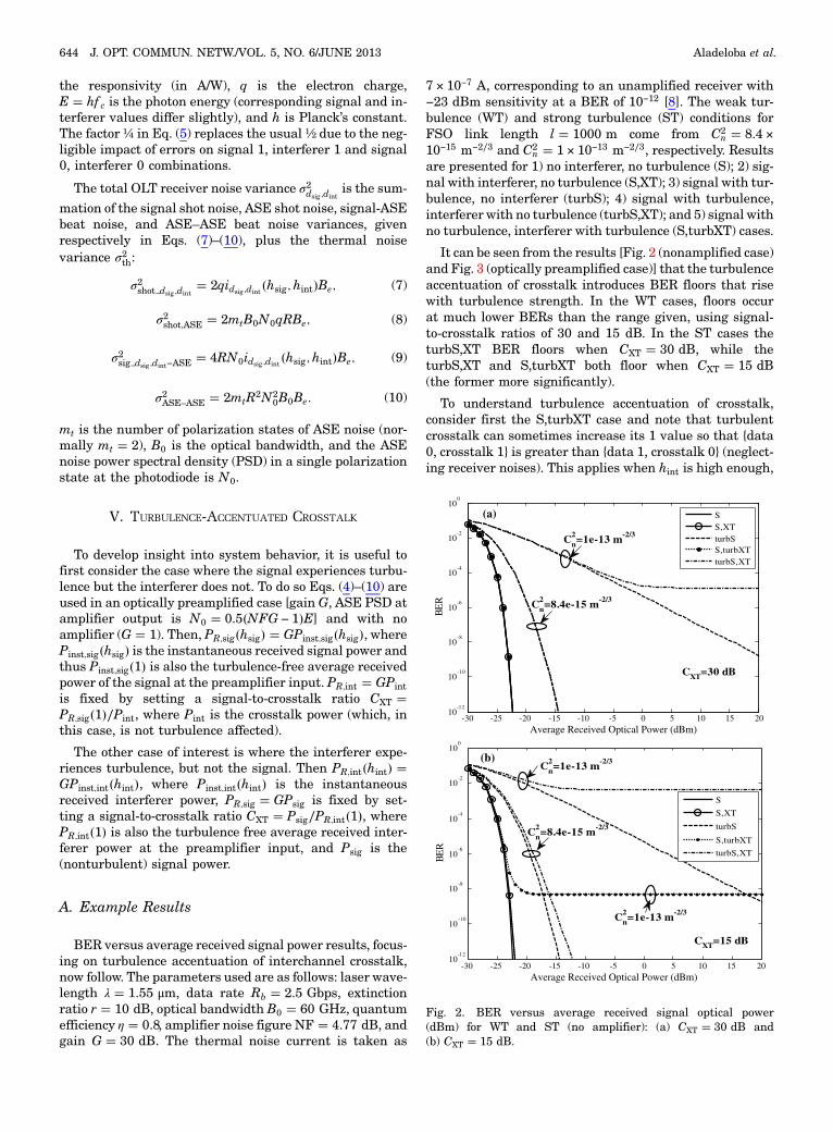
V. TURBULENCE-ACCENTUATED CROSSTALK
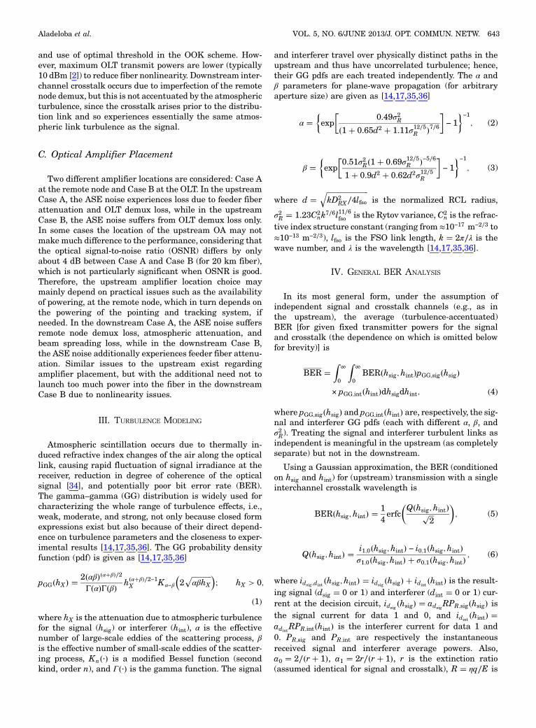
To develop insight into system behavior, it is useful tofirst consider the case where the signal experiences turbu-lence but the interferer does not. To do so Eqs. (4)–(10) areused in an optically preamplified case [gain G, ASE PSD atamplifier output is N0 � 0.5�NFG − 1�E] and with noamplifier (G � 1). Then, PR;sig�hsig� � GPinst;sig�hsig�, wherePinst;sig�hsig� is the instantaneous received signal power andthus Pinst;sig�1� is also the turbulence-free average receivedpower of the signal at the preamplifier input. PR;int � GPintis fixed by setting a signal-to-crosstalk ratio CXT �PR;sig�1�∕Pint, where Pint is the crosstalk power (which, inthis case, is not turbulence affected).
The other case of interest is where the interferer expe-riences turbulence, but not the signal. Then PR;int�hint� �GPinst;int�hint�, where Pinst;int�hint� is the instantaneousreceived interferer power, PR;sig � GPsig is fixed by set-ting a signal-to-crosstalk ratio CXT � Psig∕PR;int�1�, wherePR;int�1� is also the turbulence free average received inter-ferer power at the preamplifier input, and Psig is the(nonturbulent) signal power.
A. Example Results
BER versus average received signal power results, focus-ing on turbulence accentuation of interchannel crosstalk,now follow. The parameters used are as follows: laser wave-length λ � 1.55 μm, data rate Rb � 2.5 Gbps, extinctionratio r � 10 dB, optical bandwidth B0 � 60 GHz, quantumefficiency η � 0.8, amplifier noise figure NF � 4.77 dB, andgain G � 30 dB. The thermal noise current is taken as
7 × 10⁻⁷ A, corresponding to an unamplified receiver with−23 dBm sensitivity at a BER of 10−12 [8]. The weak tur-bulence (WT) and strong turbulence (ST) conditions forFSO link length l � 1000 m come from C2
n � 8.4 ×10⁻¹⁵ m−2∕3 and C2
n � 1 × 10⁻¹³ m−2∕3, respectively. Resultsare presented for 1) no interferer, no turbulence (S); 2) sig-nal with interferer, no turbulence (S,XT); 3) signal with tur-bulence, no interferer (turbS); 4) signal with turbulence,interferer with no turbulence (turbS,XT); and 5) signal withno turbulence, interferer with turbulence (S,turbXT) cases.
It can be seen from the results [Fig. 2 (nonamplified case)and Fig. 3 (optically preamplified case)] that the turbulenceaccentuation of crosstalk introduces BER floors that risewith turbulence strength. In the WT cases, floors occurat much lower BERs than the range given, using signal-to-crosstalk ratios of 30 and 15 dB. In the ST cases theturbS,XT BER floors when CXT � 30 dB, while theturbS,XT and S,turbXT both floor when CXT � 15 dB(the former more significantly).
To understand turbulence accentuation of crosstalk,consider first the S,turbXT case and note that turbulentcrosstalk can sometimes increase its 1 value so that {data0, crosstalk 1} is greater than {data 1, crosstalk 0} (neglect-ing receiver noises). This applies when hint is high enough,
-30 -25 -20 -15 -10 -5 0 5 10 15 2010
-12
10-10
10-8
10-6
10-4
10-2
100
Average Received Optical Power (dBm)
BE
R
SS,XTturbSS,turbXTturbS,XT
CXT=30 dB
(a)
Cn2=1e-13 m-2/3
Cn2=8.4e-15 m-2/3
-30 -25 -20 -15 -10 -5 0 5 10 15 20Average Received Optical Power (dBm)
S
S,XT
turbS
S,turbXT
turbS,XT
(b)
CXT=15 dB
Cn2=8.4e-15 m-2/3
Cn2=1e-13 m-2/3
Cn2=1e-13 m-2/3
10-12
10-10
10-8
10-6
10-4
10-2
100
BE
R
Fig. 2. BER versus average received signal optical power(dBm) for WT and ST (no amplifier): (a) CXT � 30 dB and(b) CXT � 15 dB.
644 J. OPT. COMMUN. NETW./VOL. 5, NO. 6/JUNE 2013 Aladeloba et al.

and when it is (as when the data rate is much faster thanthe turbulence), it effectively holds this value long enoughfor the threshold to adapt and be set above the {data 1,crosstalk 0} value but below {data 0, crosstalk 1} value,inevitably leading to errors (except when receiver noisesoperate to correct them). This occurs when hint > CXT, sointegrating this tail of the crosstalk’s turbulence pdf setsthe error floor. The floor starts once the signal powerand crosstalk are sufficiently large that the noises are veryunlikely to cause a reverse threshold crossing. Similar ar-guments apply for the turbS,XT case, except this time therecomes a point, by attenuating the signal, where {data 1,crosstalk 0} is brought lower than {data 0, crosstalk 1},again neglecting receiver noises and leading to a thresholdset below {data 0, crosstalk 1} and above {data 1, crosstalk0}. This occurs when hsig < 1∕CXT, setting the error floorvalue via integration of the signal’s turbulence pdf.
VI. BER EVALUATION FOR HYBRID
WDM PON FSO SYSTEM
A. Upstream Transmission
Equations (4)–(10) can now be used for the specificsystem calculations that follow. The single crosstalk is
relevant where a dominant interferer exists (e.g., in somesparsely populated dense wavelength division multiplex-ing grids or where particular interferer transmitters arehigher powered). There is also the possibility of schemeswhere some distribution links are fiber and some areFSO. Now the average received optical power values atthe OLT photodiode for the desired signal and interfererare given, respectively, as
PR;sig�hsig� � GPuT;sighsigLfso;sigLbs;sigLc;sigLmuxLfiberLdemux;
(11)
PR;int�hint� � GPuT;inthintLfso;intLbs;intLc;int
× LmuxLfiberLdemuxLdemux;XT; (12)
where Ldemux;XT is the additional loss (above Ldemux) the in-terferer has when coupled onto the signal photodiode bythe demux. PuT;sig
and PuT;intare respectively the signal
and interferer ONU transmit powers. In principle, thesecould be allowed to differ under a power control algorithm.Lfso � 10�−αfsolfso∕10� is the atmospheric loss (αfso in dB∕km),and Lfiber � 10�−αfiberlfiber∕10� is the fiber loss (αfiber in dB∕km).The loss due to beam spreading Lbs in the FSO link, forsignal and interferer, comes from [3,14]
Lbs ��DRX
θlfso
2
�13�
and can be stated separately for the signal and interferer.
Under the assumption that the end facet of the shortsingle mode fiber leading to the mux is positioned in thefocal plane of the RCL, the coupling loss for the signaland interferer can be calculated from [37]
Lc � 1−
8>><>>:8a2
Z1
0
Z1
0
0BB@exp
h−
�a2 � ARX
AC
��x21 � x22�
i
×I0
�2ARX
ACx1x2
x1x2
1CCAdx1dx2
9>>=>>;;
(14)
where a is the ratio of the RCL radius to the backpropa-gated fiber mode radius, ARX � πD2
RX∕4 is the RCL area,AC � πρ2C is the spatial coherence area of the incident planewave, ρC � �1.46C2
nk2lfso�−3∕5 is the spatial coherence ra-dius, and I0�·� is a modified Bessel function (first kind,zeroth order). Calculations will use a � 1.12, which corre-sponds to the optimum value for a fully coherent incidentplane wave.
At the amplifier output the ASE PSD is N0OA �0.5�NFG − 1�E. Different values of N0 arise dependingon the OA position. In the upstream Case A, the receivedASE noise PSD can be written as N0 � N0OALfiberLdemux,while in Case B, the received ASE noise PSD can be writtenas N0 � N0OALdemux.
-60 -50 -40 -30 -20 -10 0 10 20Average Received Optical Power (dBm)
SS,XTturbSS,turbXTturbS,XT
CXT=30 dB
(a) Cn2=1e-13 m-2/3
Cn2=8.4e-15 m-2/3
-60 -50 -40 -30 -20 -10 0 10 2010
-12
10-10
10-8
10-6
10-4
10-2
100
Average Received Optical Power (dBm)
BE
R
SS,XTturbSS,turbXTturbS,XT
CXT=15 dB
(b)
Cn2=1e-13 m-2/3
Cn2=8.4e-15 m-2/3
Cn2=1e-13 m-2/3
10-12
10-10
10-8
10-6
10-4
10-2
100
BE
R
Fig. 3. BER versus average received signal optical power (dBm)for WT and ST (G � 30 dB): (a) CXT � 30 dB and (b) CXT � 15 dB.
Aladeloba et al. VOL. 5, NO. 6/JUNE 2013/J. OPT. COMMUN. NETW. 645
B. Downstream Transmission
The downstream interchannel crosstalk is not turbulence-accentuated, as (neglecting wavelength difference impact onσ2R) it traverses the same atmospheric path as the signal.The downstream BER (conditioned on hX ) (for given fixedtransmitter powers for the signal and crosstalk, the depend-ence on which is omitted below for brevity) is
BERd�hX � �14erfc
�Qd�hX����
2p
; (15)
Qd�hX � �id1;0
�hX� − id0;1�hX �
σd1;0�hX� � σd0;1
�hX �; (16)
where iddsig ;dint�hX� � iddsig
�hX� � iddint�hX� is the signal
(dsig � 0, 1) plus interferer (dint � 0, 1) current at the ONUdecision circuit. iddsig
�hX� � adsigRPdRsig
�hX� and iddint�hX � �
adintRPdRint
�hX� are the downstream signal and interferer
currents.
The average received optical power at the ONU photo-diodes for signal and interferer, respectively, are
PdR;sig�hX � � GPdT;sig
hXLmuxLfiberLdemuxLfsoLbs; (17)
PdR;int�hX � � GPdT;int
hXLmuxLfiberLdemuxLdemux;XTLfsoLbs;
(18)
where PdT;sigand PdT;int
are the respective downstreamtransmit powers. Equations (7)–(10) may again be usedfor the electrical domain noises, though the hX classifica-tion as hsig and hint disappears in the downstream.
In the downstream Case A, the effective ASE noisePSD in the single polarization state at the photodiode isgiven as N0 � N0OALdemux;sigLfso;sigLbs;sig, while in CaseB, it is given as N0 � N0;OALfiberLdemux;sigLfso;sigLbs;sig.
The average downstream BER is given as
BERd;av �Z
∞
0BERd�hX�pGG;sig�hX�dhX: (19)
VII. RESULTS AND DISCUSSION
Results in terms of required optical power are presentedto predict the performance for various scenarios of the hy-brid WDM network. Turbulent conditions considered areC2
n � 10−17 m−2∕3, C2n � 10−15 m−2∕3, and C2
n � 10−13 m−2∕3.If the resulting σ2R < 1, we haveWT; if σ2R ≈ 1, we have mod-erate turbulence; and if σ2R > 1, we have ST. The requiredoptical power used here is the transmitter power for a BERof 10−6. Much better performance can be achieved with theuse of forward error correction (FEC). Note, however, thatthe precise relationship between the long-time averageBER before and after FEC would require FEC to enter
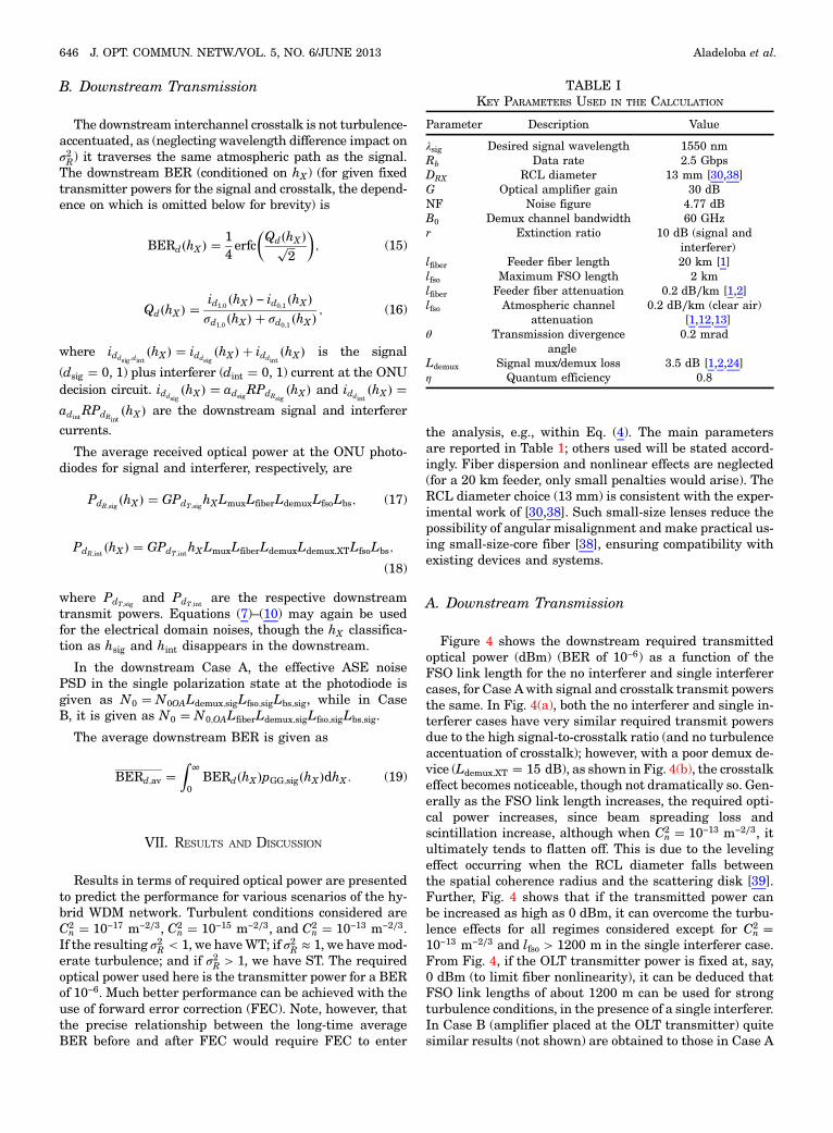
the analysis, e.g., within Eq. (4). The main parametersare reported in Table 1; others used will be stated accord-ingly. Fiber dispersion and nonlinear effects are neglected(for a 20 km feeder, only small penalties would arise). TheRCL diameter choice (13 mm) is consistent with the exper-imental work of [30,38]. Such small-size lenses reduce thepossibility of angular misalignment and make practical us-ing small-size-core fiber [38], ensuring compatibility withexisting devices and systems.
A. Downstream Transmission
Figure 4 shows the downstream required transmittedoptical power (dBm) (BER of 10−6) as a function of theFSO link length for the no interferer and single interferercases, for Case Awith signal and crosstalk transmit powersthe same. In Fig. 4(a), both the no interferer and single in-terferer cases have very similar required transmit powersdue to the high signal-to-crosstalk ratio (and no turbulenceaccentuation of crosstalk); however, with a poor demux de-vice (Ldemux;XT � 15 dB), as shown in Fig. 4(b), the crosstalkeffect becomes noticeable, though not dramatically so. Gen-erally as the FSO link length increases, the required opti-cal power increases, since beam spreading loss andscintillation increase, although when C2
n � 10−13 m−2∕3, itultimately tends to flatten off. This is due to the levelingeffect occurring when the RCL diameter falls betweenthe spatial coherence radius and the scattering disk [39].Further, Fig. 4 shows that if the transmitted power canbe increased as high as 0 dBm, it can overcome the turbu-lence effects for all regimes considered except for C2
n �10−13 m−2∕3 and lfso > 1200 m in the single interferer case.From Fig. 4, if the OLT transmitter power is fixed at, say,0 dBm (to limit fiber nonlinearity), it can be deduced thatFSO link lengths of about 1200 m can be used for strongturbulence conditions, in the presence of a single interferer.In Case B (amplifier placed at the OLT transmitter) quitesimilar results (not shown) are obtained to those in Case A
TABLE IKEY PARAMETERS USED IN THE CALCULATION
Parameter Description Value
λsig Desired signal wavelength 1550 nmRb Data rate 2.5 GbpsDRX RCL diameter 13 mm [30,38]G Optical amplifier gain 30 dBNF Noise figure 4.77 dBB0 Demux channel bandwidth 60 GHzr Extinction ratio 10 dB (signal and
interferer)lfiber Feeder fiber length 20 km [1]lfso Maximum FSO length 2 kmlfiber Feeder fiber attenuation 0.2 dB∕km [1,2]lfso Atmospheric channel
attenuation0.2 dB∕km (clear air)
[1,12,13]θ Transmission divergence
angle0.2 mrad
Ldemux Signal mux/demux loss 3.5 dB [1,2,24]η Quantum efficiency 0.8
646 J. OPT. COMMUN. NETW./VOL. 5, NO. 6/JUNE 2013 Aladeloba et al.

above due to the low loss of the fiber. However, the mainissue for Case B is the low permitted transmitter power(about −10 dBm [8]) due to fiber nonlinearity issues.Having −10 dBm as the maximum transmitter power willclearly limit the FSO link length.
Figure 5 shows the downstream required transmittedoptical power (for BER of 10−6) as a function of the trans-mitter divergence angle with lfso � 1000 m for no interfererand single interferer cases [Fig. 5(a), Ldemux;XT � 30 dB,and Fig. 5(b), Ldemux;XT � 15 dB]. The required opticalpower clearly increases with the transmit divergenceand turbulence strength. Comparing Figs. 5(a) and 5(b)shows the crosstalk impact of a poor demux device. For non-tracking systems with relatively large transmit divergence(>1 mrad), more power than in tracking systems will berequired. This system type would be required to havegreater beam widths in order to compensate for any mo-tions due to building sway. For systems with automaticpointing and tracking, the transmit divergence anglecan be narrowed sufficiently (typically with divergence≪1 mrad), which allows for a secure transmission andlarger proportion of transmitted power being collected.Thus the required transmitted power for tracking systemsis lower. From Fig. 5, assuming a transmitter power of, say,
0 dBm (possible in Case A), in order to achieve a BER of10−6 and lfso of 1000 m, a small transmit divergence angle(about 0.12 mrad) has to be used, and this can be achievedby using a tracking system. Although tracking helps im-prove system performance, it also adds considerable costand complexity to the FSO-based distribution link, particu-larly if required for each ONU. Tracking systems also havepointing jitter errors [40] not included here. In a nontrack-ing system with single crosstalk (and transmit divergenceof 2 mrad), the maximum FSO link length in Case A (maxi-mum transmit power of 0 dBm) is just less than 800 m,while in Case B (with maximum transmit power of−10 dBm) the FSO link length is about 500 m.
B. Upstream Transmission
Figure 6 shows the upstream required transmitted opti-cal power at a target BER of 10−6 as a function of the FSOlink length with equal signal and interferer FSO linklengths (and transmit powers), Ldemux;XT � 30 dB, for nointerferer and single interferer Case A. On comparing
200 400 600 800 1000 1200 1400 1600 1800 2000-35
-30
-25
-20
-15
-10
-5
0
5
FSO Link Length (m)
Req
uire
d O
ptic
al P
ower
at B
ER
of
10-6
(dB
m)
No InterfererSingle Interferer
BER=10-6
(a)
Cn2=10-17 m-2/3
Cn2=10-15 m-2/3
Cn2=10-13 m-2/3
200 400 600 800 1000 1200 1400 1600 1800 2000-35
-30
-25
-20
-15
-10
-5
0
5
FSO Link Length (m)
Req
uire
d O
ptic
al P
ower
at
BE
R o
f 10
-6 (
dBm
)
No InterfererSingle InterfererBER=10-6
Cn2=10-17 m-2/3
Cn2=10-15 m-2/3
Cn2=10-13 m-2/3
(b)
Fig. 4. Downstream required transmitted optical power (dBm) ata target BER of 10−6 as a function of the FSO link length (m) for nointerferer and single interferer cases, (a) Ldemux;XT � 30 dB and(b) Ldemux;XT � 15 dB. The OA was at the remote node (Case A).
0 0.2 0.4 0.6 0.8 1 1.2 1.4 1.6 1.8 2
x 10-3
-40
-30
-20
-10
0
10
20
30
Transmitter Divergence Angle (rad)
Req
uire
d O
ptic
al P
ower
at
BE
R o
f 10
-6 (
dBm
)
No InterfererSingle Interferer
BER=10-6
Cn2=10-15 m-2/3
Cn2=10-13 m-2/3
Cn2=10-17 m-2/3
(a)
0 0.2 0.4 0.6 0.8 1 1.2 1.4 1.6 1.8 2
x 10-3
-40
-30
-20
-10
0
10
20
30
Transmitter Divergence Angle (rad)
Req
uire
d O
ptic
al P
ower
at B
ER
of
10-6
(dB
m)
No InterfererSingle InterfererBER=10-6
Cn2=10-17 m-2/3
Cn2=10-15 m-2/3
Cn2=10-13 m-2/3
(b)
Fig. 5. Downstream required transmitted optical power (dBm) ata target BER of 10−6 as a function of the transmitter divergenceangle (rad) with lfso � 1000 m for no interferer and single inter-ferer cases, (a) Ldemux;XT � 30 dB and (b) Ldemux;XT � 15 dB. TheOA was at the remote node (Case A).
Aladeloba et al. VOL. 5, NO. 6/JUNE 2013/J. OPT. COMMUN. NETW. 647

the upstream and downstream results (OLT demux loss of30 dB), i.e., Figs. 6 and 4(a), it can be seen that the requiredtransmit power is higher in the upstream case (Fig. 6) (e.g.,by about 6 dB when C2
n � 10−13 m−2∕3 and lfso � 2000 m).While turbulence accentuation of crosstalk will occur, itis not the dominant issue here due to the assumption ofsimilar crosstalk and signal powers and lengths. The mainfactors leading to higher upstream required power are theadditional coupling loss via the RCL into fiber that occursin the upstream (in the downstream we can couple directlyonto the photodiode) and the fact that the upstream re-ceived OSNR is typically worse. In the upstream, theONU transmit power can be up to 10 dBm, which fulfilseye-safety conditions for a C-band wavelength range[40]. Therefore, using a reference power of 10 dBm in Fig. 6,it can be seen that an FSO link length of about 2000 m canbe used to achieve the target BER value for all atmosphericturbulence conditions with a single interferer.
Figure 7 shows the upstream required transmitted opti-cal power (BER of 10−6) against the transmitter divergenceangle for no interferer and single interferer cases withlfso � 1000 mand Ldemux;XT � 30 dB. As in the downstream[Fig. 5(a)], the required transmitter power increases withtransmitter divergence and in the presence of crosstalk,although the required powers are greater in the upstreamthan the downstream case for similar reasons mentionedearlier (the ASE loss). Using a transmit power of 10 dBm,a tracking system would be required to achieve a smalltransmit divergence, FSO link length of 1000 m, andBER of 10−6 for the whole range of atmospheric turbulenceconditions, while in a nontracking system with a diver-gence of 2 mrad, the maximum FSO link length is about500 m at a BER of 10−6 for an ST condition.
So far it has been assumed that the signal and interfererhave identical launch power and distance. The distance re-quirement is now set aside (but that on launch powerretained). Figure 8 shows the upstream required transmit-ted optical power (BER of 10−6) versus FSO link lengths for
signal and interferer for the single interferer case withLdemux;XT � 15 dB. It can be seen from Fig. 8 that whenthe interferer is closer to the remote node than the desiredsignal, the crosstalk effect becomes more significant and
200 400 600 800 1000 1200 1400 1600 1800 2000-25
-20
-15
-10
-5
0
5
10
FSO Link Length (m)
Req
uire
d O
ptic
al P
ower
at B
ER
of
10-6
(dB
m)
No InterfererSingle Interferer
BER=10-6
Cn2=10-17 m-2/3
Cn2=10-15 m-2/3Cn
2=10-13 m-2/3
Fig. 6. Upstream required transmitted optical power (dBm) attarget BERs of 10−6 as a function of the FSO link length (m) forno interferer and single interferer cases, Ldemux;XT � 30 dB.
0 0.2 0.4 0.6 0.8 1 1.2 1.4 1.6 1.8 2
x 10-3
-40
-30
-20
-10
0
10
20
30
40
Transmitter Divergence Angle (rad)
Req
uire
d O
ptic
al P
ower
at B
ER
of
10-6
(dB
m)
No InterfererSingle Interferer
Cn2=10-17 m-2/3
Cn2=10-15 m-2/3
Cn2=10-13 m-2/3
BER=10-6
Fig. 7. Upstream required transmitted optical power (dBm) attarget BERs of 10−6 as a function of the transmitter divergenceangle (rad) with lfso � 1000 m for no interferer and single inter-ferer cases, Ldemux;XT � 30 dB.
0
500
1000
1500
0
500
1000
1500-40
-20
0
20
40
lfso,int (m)lfso,sig (m)
Req
uire
d O
ptic
al P
ower
at B
ER
of
10-6
(dB
m)
Cn2=10-15 m-2/3
0
500
1000
1500
0
500
1000
1500-40
-20
0
20
40
lfso,int (m)lfso,sig (m)
Req
uire
d O
ptic
al P
ower
at B
ER
of
10-6
(dB
m)
Cn2=10-13 m-2/3
Fig. 8. Upstream required transmitted optical power (dBm) attarget BERs of 10−6 as a function of the FSO link lengths forsignal and interferer (m) for the single interferer case withLdemux;XT � 15 dB.
648 J. OPT. COMMUN. NETW./VOL. 5, NO. 6/JUNE 2013 Aladeloba et al.

the required transmit power increases. Furthermore, thesudden increase in required power seen on the left of Fig. 8(for both turbulence strengths considered), i.e., when theFSO link length of the interferer is much closer (less than200m) to the remote node and the signal FSO link length isfarther away (say about 1500m), can be related to the sameturbulence accentuation effect that led to error floors in theturbS,XT case discussed earlier [see Fig. 3(b)]. In fact, forsome FSO link length combinations it is not possible toattain the target BER requirement.
Figure 9 again shows the upstream required transmit-ted optical power (BER of 10−6) as a function of the FSOlink lengths for the signal and single interferer withLdemux;XT � 15 dB. However, unlike Fig. 8, now there is as-sumed a power control algorithm that ensures the averagepower at the RCL or OLT for each signal is fixed. A similarargument as in Fig. 8 can be established here, but in thiscase it relates to the turbulence accentuating of the inter-ferer, S,turbXT case (since the effect of turbulence would begreater on the interferer than the desired signal in the re-gions). Also at some point when lfso;sig ≪ lfso;int, there wouldbe occurrence of an error floor, which restricts the
attainment of the target BER. In regions without BERfloor effects, this power control approach increases the re-quired optical power to attain the target BERs comparedto Fig. 8.
VIII. CONCLUSION
In this paper, a WDM network incorporating FSO com-munications for the distribution link has been studied. Itcan be deduced from this analysis that interchannel cross-talk, turbulence-induced scintillation, and ASE noises aredominant causes of system degradation, especially in theupstream transmission, causing the BER to increase byseveral orders of magnitude. The results obtained indicatethat in a clear atmosphere with a sufficiently high signal-to-crosstalk ratio, the proposed system can achieve human-safe and high-capacity access networks. The location of theOA will make little difference to the performance calcula-tions in both directions, but the issue of capping of the fiberlaunch power is significant in the downstream. Finally,the OA positioning would also depend on other design con-siderations, such as fiber nonlinearity and powering of apointing and tracking system at the remote node.
REFERENCES
[1] C. H. Lee, W. V. Sorin, and B. Y. Kim, “Fiber to the home usinga PON infrastructure,” J. Lightwave Technol., vol. 24,pp. 4568–4583, 2006.
[2] J. Prat, Next-Generation FTTH Passive Optical Networks:Research Towards Unlimited Bandwidth Access. Springer,2008.
[3] S. Bloom, E. Korevaar, J. Schuster, and H. A. Willebrand,“Understanding the performance of free-space optics,”J. Opt. Netw., vol. 2, pp. 178–200, June 2003.
[4] D. O. Caplan, “Laser communication transmitter and receiverdesign,” J. Opt. Fiber Commun. Rep., vol. 4, pp. 225–362,2007.
[5] T. H. Carbonneau and D. R. Wisely, “Opportunities andchallenges for optical wireless: the competitive advantageof free space telecommunications links in today’scrowded marketplace,” Proc. SPIE, vol. 3232, pp. 119–128,Jan. 1998.
[6] D. Killinger, “Free space optics for laser communicationthrough the air,” Opt. Photon. News, vol. 13, no. 10, pp. 36–42,Oct. 2002.
[7] S. Karp, R. M. Gagliardi, S. E. Moran, and L. B. Stotts,OpticalChannels: Fibers, Clouds, Water and the Atmosphere.New York: Plenum, 1988.
[8] R. Ramaswami and K. N. Sivarajan, Optical Networks—APratical Perspective, 2nd ed. London: Academic, 2002.
[9] R. P. Davey, D. B. Grossman, M. Rasztovits-Wiech, D. B.Payne, D. Nesset, A. E. Kelly, A. Rafel, S. Appathurai, andS. Yang, “Long-reach passive optical networks,” J. LightwaveTechnol., vol. 27, pp. 273–291, Feb. 2009.
[10] E. Ciaramella, Y. Arimoto, G. Contestabile, M. Presi, A.D’Errico, V. Guarino, and M. Matsumoto, “1.28 terabit∕s(32 × 40 Gbit∕s) WDM transmission system for free space op-tical communications,” IEEE J. Sel. Areas Commun., vol. 27,pp. 1639–1645, 2009.
0500
10001500
2000
0
500
1000-10
0
10
20
30
40
lfso,int (m)lfso,sig (m)
Req
uire
d O
ptic
al P
ower
at B
ER
of
10-6
(dB
m)
Cn2=10-15 m-2/3
0500
10001500
2000
0
500
1000-10
0
10
20
30
40
lfso,int (m)lfso,sig (m)
Req
uire
d O
ptic
al P
ower
at B
ER
of
10-6
(dB
m)
Cn2=10-13 m-2/3
Fig. 9. Upstream required transmitted optical power (dBm)(under the assumption of a power control algorithm that ensuresthe average power at the RCL or OLT for each signal is fixed) attarget BERs of 10−6 as a function of the FSO link lengths forsignal and interferer (m) for the single interferer case withLdemux;XT � 15 dB.
Aladeloba et al. VOL. 5, NO. 6/JUNE 2013/J. OPT. COMMUN. NETW. 649

[11] L. Kazovsky, S.-W. Wong, T. Ayhan, K. M. Albeyoglu,M. R. N. Ribeiro, and A. Shastri, “Hybrid optical wirelessaccess networks,” Proc. IEEE, vol. 100, pp. 1197–1225, 2012.
[12] E. S. Son, K. H. Han, J. H. Lee, and Y. C. Chung, “Survivablenetwork architectures for WDM PON,” Optical FiberCommunication Conf. (OFC), Anaheim, CA, Mar. 2005,paper OFI4.
[13] E. Leitgeb, M. Gedhart, and U. Birnbacher, “Opticalnetworks, last mile access and applications,” J. Opt. FiberCommun. Rep., vol. 2, pp. 56–85, 2005.
[14] A. K. Majumdar, “Free-space laser communication perfor-mance in the atmospheric channel,” J. Opt. Fiber Commun.Rep., vol. 2, pp. 345–396, 2005.
[15] J. C. Ricklin, S. M. Hammel, F. D. Eaton, and S. L. Lachinova,“Atmospheric channel effects on free-space laser communica-tion,” J. Opt. Fiber Commun. Rep., vol. 3, pp. 111–158,2006.
[16] H. A. Willebrand and B. S. Ghuman, Free-Space Optics:Enabling Optical Connectivity in Today’s Networks.Indianapolis, IN: Sams, 2002.
[17] L. C. Andrews and R. L. Phillips, Laser Beam PropagationThrough Random Media, 2nd ed. Bellingham, WA: SPIE,2005.
[18] E. Korevaar, I. Kim, and B. McArthur, “Atmospheric propaga-tion characteristics of highest importance to commercial freespace optics,” Proc. SPIE, vol. 4976, pp. 1–12, 2003.
[19] T. Kamalakis, I. Neokosmidis, A. Tsipouras, S. Pantazis, andI. Andrikopoulos, “Hybrid free space optical/millimeter waveoutdoor links for broadband wireless access networks,” inIEEE 18th Int. Symp. on Personal, Indoor and Mobile RadioCommunications, Athens, Greece, 2007.
[20] M. Abtahi, P. Lemieux, W. Mathlouthi, and L. A. Rusch,“Suppression of turbulence-induced scintillation in free-spaceoptical communication systems using saturated opticalamplifiers,” J. Lightwave Technol., vol. 24, pp. 4966–4973,2006.
[21] A. O. Aladeloba, A. J. Phillips, and M. S. Woolfson, “Improvedbit error rate evaluation for optically pre-amplified free-spaceoptical communication systems in turbulent atmosphere,”IET Optoelectron., vol. 6, pp. 26–33, Feb. 2012.
[22] M. Razavi and J. H. Shapiro, “Wireless optical communica-tions via diversity reception and optical preamplification,”IEEE Trans. Wireless Commun., vol. 4, pp. 975–983,2005.
[23] A. J. Phillips, J. M. Senior, R. Mercinelli, M. Valvo, P. J. Vetter,C. M. Martin, M. O. Van Deventer, P. Vaes, and X. Z. Qiu,“Redundancy strategies for a high splitting optically ampli-fied passive optical network,” J. Lightwave Technol., vol. 19,pp. 137–149, 2001.
[24] I. T. Monroy and E. Tangdiongga, Crosstalk in WDMCommunication Networks. Norwell, MA: Kluwer Academic,2002.
[25] D. M. Forin, S. Di Bartolo, G. M. Toshi Beleffi, F. Curti, G.Cincotti, A. Vecchi, S. Ragana, and A. L. J. Teixeira, “GigaEthernet free-space passive optical networks,” Fiber Integr.Opt., vol. 27, pp. 229–236, Apr. 2008.
[26] K. Wang, A. Nirmalathas, C. Lim, and E. Skafidas,“4 × 12.5 Gb∕s WDM optical wireless communication systemfor indoor applications,” J. Lightwave Technol., vol. 29,pp. 1988–1996, July 2011.
[27] A. J. Phillips, “Power penalty for burst mode reception in thepresence of interchannel crosstalk,” IET Optoelectron., vol. 1,pp. 127–134, 2007.
[28] C. X. Yu and D. T. Neilson, “Diffraction-grating-based(de)multiplexer using image plane transformations,” IEEEJ. Sel. Top. Quantum Electron., vol. 8, pp. 1194–1201, 2002.
[29] S. B. Alexander, Optical Communication Receiver Design(SPIE Tutorial Texts in Optical Engineering, Vol. TT22).Bellingham, WA: SPIE, 1997.
[30] F. S. Vetelino, C. Young, L. Andrews, and J. Recolons, “Aper-ture averaging effects on the probability density of irradiancefluctuations in moderate-to-strong turbulence,” Appl. Opt.,vol. 46, pp. 2099–2108, Apr. 2007.
[31] “Safety of Laser Products—Part 1: Equipment Classification,Requirements, and User’s Guide, New classification standardadopted as of 1 March 2001, Amendment 2,” InternationalElectrotechnical Commission, IEC 60825-1, 2001 [Online]Available: http://www.iec.ch/.
[32] N. S. Kopeika and A. Zilberman, “Vertical profiles of aerosoland optical turbulence strength and their effects on atmos-pheric propagation,” Proc. SPIE, vol. 3927, pp. 460–467,2000.
[33] C. Chen, H. Yang, H. Jiang, J. Fan, C. Han, and Y. Ding, “Mit-igation of turbulence-induced scintillation noise in free-spaceoptical communication links using Kalman filter,” IEEECongr. on Image and Signal Processing, China, Hainan,May 2008, vol. 5, pp. 470–473.
[34] D. J. Wheeler and J. D. Schmidt, “Spatial coherence functionof partially coherent Gaussian beams in atmospheric turbu-lence,” Appl. Opt., vol. 50, pp. 3907–3917, 2011.
[35] M. A. Al-Habash, L. C. Andrews, and R. L. Phillips, “Math-ematical model for the irradiance probability density functionof a laser beam propagating through turbulent media,” Opt.Eng., vol. 40, pp. 1554–1562, Aug. 2001.
[36] M. A. Khalighi, N. Schwartz, N. Aitamer, and S. Bourennane,“Fading reduction by aperture averaging and spatial diver-sity in optical wireless systems,” J. Opt. Commun. Netw.,vol. 1, pp. 580–593, 2009.
[37] Y. Dikmelik and F. M. Davidson, “Fiber-coupling efficiencyfor free-space optical communication through atmosphericturbulence,” Appl. Opt., vol. 44, pp. 4946–4952, Aug. 2005.
[38] S. Spaunhorst, P. G. LoPresti, S. Pondelik, and H. Refai,“Evaluation of a novel FSO receiver for mitigating alignmenterrors,” Proc. SPIE, vol. 7324, 73240H, 2009.
[39] A. O. Aladeloba, A. J. Phillips, and M. S. Woolfson,“Performance evaluation of optically preamplified digitalpulse position modulation turbulent free-space optical com-munication systems,” IET Optoelectron., vol. 6, pp. 66–74,Feb. 2012.
[40] A. O. Aladeloba, A. J. Phillips, and M. S. Woolfson, “DPPMFSO communication systems impaired by turbulence, point-ing error and ASE noise,” in 14th Int. Conf. on TransparentOptical Networks (ICTON), Coventry, UK, 2012.
Abisayo O. Aladeloba (S’11) received abachelor’s degree in physics from theFederal University of Technology, Akure,Nigeria, in 2006. He received an M.Sc.degree in electronic, communications, andcomputer engineering from the Universityof Nottingham, UK, in 2009, where he is cur-rently working toward a Ph.D. degree. Hisresearch interests are in wireless opticalcommunication, modulation techniques forfree-space optical communication systems,
optical amplifiers, optical performance, and direct detectionreceiver modeling.
650 J. OPT. COMMUN. NETW./VOL. 5, NO. 6/JUNE 2013 Aladeloba et al.

Malcolm S. Woolfson graduated in 1978with a B.Sc. in mathematics and physicsfrom the University of Bristol. Between1978 and 1981 he was a research studentin the Department of Physics at the Univer-sity of Warwick, where he worked in thearea of surface physics; he was awarded aPh.D. degree in 1982. Between 1981 and1983 he was employed as a ResearchAssistant in the Department of Physics atthe University of Sheffield, where he carried
out research into the dynamics of atoms in liquids. In 1983 hejoined the Marconi Research Centre in Chelmsford, where heworked in the area of signal and data processing techniques fortracking radar. Since 1987 he has been a Lecturer in SignalProcessing in the Department of Electrical and ElectronicEngineering at the University of Nottingham. He has beeninvolved in the application of a variety of signal and image process-ing techniques to various areas of engineering.
Andrew J. Phillips obtained his B.Sc.(Hons.) in mathematics from the Universityof Manchester in 1990, his M.Sc. in appliedoptics from the University of Salford in1992, and his Ph.D. in optical communica-tions from Manchester MetropolitanUniversity (MMU) in 1995. He undertookpostdoctoral work at MMU between 1995and 2000, including work on the EUACTS-PLANET project, and joined MarconiCommunications in 2000. He took up his
present post at the University of Nottingham as Lecturer in Pho-tonic Communications Technology in January 2003. His researchinterests include optical amplification, regeneration, optical ac-cess, free-space optical communication, optical performance mon-itoring, and BER evaluation. He has published over 70 papers injournals and conferences. Dr. Phillips is a Member of the Institu-tion of Engineering and Technology.
Aladeloba et al. VOL. 5, NO. 6/JUNE 2013/J. OPT. COMMUN. NETW. 651