Cancellation of image crosstalk in time-sequential displays of stereoscopic video
12
IEEE TRANSACTIONS ON IMAGE PROCESSING, VOL. 9, NO. 5, PP.897–908, MAY 2000 1 Cancellation of image crosstalk in time-sequential displays of stereoscopic video Janusz Konrad, Senior Member, IEEE, Bertrand Lacotte and Eric Dubois, Fellow, IEEE c 2000 IEEE. Personal use of this material is permitted. However, permission to reprint/republish this material for advertising or promotional purposes or for creating new collective works for resale or redistribution to servers or lists, or to reuse any copyrighted component of this work in other works must be obtained from the IEEE. Abstract—Stereoscopic visualization systems based on liquid crystal shutter (LCS) eyewear and cathode-ray tube (CRT) dis- plays provide today the best overall quality of 3-D images and therefore have a dominant position in commercial as well as pro- fessional markets. Due to the CRT and LCS characteristics, how- ever, such systems suffer from perceptual crosstalk (“shadows”) at object boundaries that can reduce, and at times inhibit, the ability to perceive depth. In this paper, we propose a method to reduce such crosstalk. We present a simple model for intensity leak, we assess model parameters for a time-sequential LCS/CRT system and we propose a computationally-efficient algorithm to eliminate the crosstalk. Since the full crosstalk elimination implies an unac- ceptable image degradation (reduction of contrast), we study the trade-off between crosstalk elimination and image contrast. We describe experiments on synthetic and natural stereoscopic images and we discuss informal subjective viewing of processed images. Overall, the viewer response has been very positive; 3-D percep- tion of many objects became either much easier or even effortless. Since the proposed algorithm can be easily implemented in real time (only linear scaling and table look-up are needed), we believe that it can be successfully used today in various stereoscopic ap- plications suffering from image crosstalk. This is particularly true for PC-based 3-D viewing where the algorithm can be executed by the CPU or by an advanced graphics board. Index Terms—Stereoscopic displays, stereoscopic and 3-D imag- ing, 3-D TV I. I NTRODUCTION T HE recent increase of interest in stereoscopic and 3-D imaging can be traced to two sources. First, stereoscopic imaging has been successfully used for a number of years in such applications as medicine (3-D microscopy, ultrasound, training), science (3-D visualization) and remote guidance (re- mote manipulation using 3-D imaging feedback). Today, how- ever, stereoscopic imaging is finding its way into homes via computer games and is expected to dramatically change TV, multimedia and electronic cinema in the near future. Secondly, the electronics industry is devoting a great deal of effort to the development of maximally realistic visual communications, high-definition TV (HDTV) services being the prime example. The next logical step to increase the realism of visual commu- nications is to include the 3-D (depth) information [7]. This is usually achieved by means of time-sequential display with J. Konrad is with INRS-T´ el´ ecommunications, 16 Place du Commerce, Ver- dun, QC, H3E 1H6, Canada ([email protected]). E. Dubois is with the School of Information Technology and Engineering, Univer- sity of Ottawa, Ottawa, ON, K1N 6N5, Canada ([email protected]). B. Lacotte worked on this project during a five-month training period at INRS- T´ el´ ecommunications in 1995 on leave from Ecole Nationale Superieure de T´ el´ ecommunication, 46 rue Barrault, 75634 Paris Cedex 13, France. This work was supported by the Natural Sciences and Engineering Research Council of Canada under research grant OGP121619 and by the Fonds pour la formation de chercheurs et l’aide ` a la recherche (FCAR), Qu´ ebec, Canada under research grant 96-ER-1577. active glasses or polarized projection with passive glasses [6]. Other technologies, such as autostereoscopic displays, have not been widely accepted yet, primarily due to the inferior qual- ity that they have offered to date [8]. The recent developments in autostereoscopic non-lenticular displays [2] may, however, change this situation in the future. The success of 3-D TV and 3-D multimedia will certainly de- pend on the ability to reduce the cost of a stereoscopic system and on the acceptance of the technology by viewers. While stereoscopic camera and display technology are still experi- mental and therefore expensive, stereoscopic transmission can be achieved today at no extra cost due to the Multi-View Pro- file in MPEG-2. As for the acceptance, concerns that 20-30% of the population suffers from stereo-blindness seem to have been greatly exaggerated. As shown recently, only about 4% of young viewers are stereo-anomalous if sufficiently long stimuli (over 1 second) are presented [10]. In a time-sequential stereoscopic display, active LCS glasses are used for view separation; when the left image is presented on the screen, the left shutter is open whereas the right one remains closed [6]. When the right image arrives, the roles are reversed. To assure no flicker, each sequence (left and right) needs to be displayed at the original frame rate (50 or 60 Hz); the combined left-right sequence is then displayed at 100 or 120 Hz. A time-sequential presentation on a CRT moni- tor provides a good-quality 3-D perception, is relatively inex- pensive for small installations (a 120 Hz monitor and a few pairs of LCS glasses) and easy to set up (no optical alignment needed, easily transportable, relatively immune to vibrations, shock, etc.). When the number of viewers grows, however, the cost of LCS glasses starts to dominate. In such a scenario, the cost-effective solution may be to employ polarized passive glasses and CRT monitor equipped with a polarizing screen (liquid crystal modulator). Alternative systems use polarized projection to separate views; images are synchronous in time but overlayed spatially with orthogonal polarizations (horizon- tal/vertical or clockwise/counter-clockwise). Although cost- effective for large installations (polarized glasses are far less expensive than the LCS ones), such systems are susceptible to image misalignment since, unlike in time-sequential displays, there is no inherent alignment between the two imaging chan- nels. While film-based stereoscopic projection systems with either polarized or LCS eyewear are in daily use in Imax-3D r theatres, electronic projection setups are still experimental. It seems, however, that it will be the electronic projection com- bined with active LCS glasses that will lead to cost-effective high-quality stereoscopic cinema. Although in time-sequential systems the motion-parallax re-
Transcript of Cancellation of image crosstalk in time-sequential displays of stereoscopic video

IEEE TRANSACTIONS ON IMAGE PROCESSING, VOL. 9, NO. 5, PP. 897–908, MAY 2000 1
Cancellation of image crosstalk in time-sequentialdisplays of stereoscopic video
Janusz Konrad, Senior Member, IEEE, Bertrand Lacotte and Eric Dubois, Fellow, IEEE
c© 2000 IEEE. Personal use of this material is permitted. However, permission to reprint/republish this material for advertising or promotional purposes or for creatingnew collective works for resale or redistribution to servers or lists, or to reuse any copyrighted component of this work in other works must be obtained from the IEEE.
Abstract—Stereoscopic visualization systems based on liquidcrystal shutter (LCS) eyewear and cathode-ray tube (CRT) dis-plays provide today the best overall quality of 3-D images andtherefore have a dominant position in commercial as well as pro-fessional markets. Due to the CRT and LCS characteristics, how-ever, such systems suffer from perceptual crosstalk (“shadows”) atobject boundaries that can reduce, and at times inhibit, the abilityto perceive depth. In this paper, we propose a method to reducesuch crosstalk. We present a simple model for intensity leak, weassess model parameters for a time-sequential LCS/CRT systemand we propose a computationally-efficient algorithm to eliminatethe crosstalk. Since the full crosstalk elimination implies an unac-ceptable image degradation (reduction of contrast), we study thetrade-off between crosstalk elimination and image contrast. Wedescribe experiments on synthetic and natural stereoscopic imagesand we discuss informal subjective viewing of processed images.Overall, the viewer response has been very positive; 3-D percep-tion of many objects became either much easier or even effortless.Since the proposed algorithm can be easily implemented in realtime (only linear scaling and table look-up are needed), we believethat it can be successfully used today in various stereoscopic ap-plications suffering from image crosstalk. This is particularly truefor PC-based 3-D viewing where the algorithm can be executed bythe CPU or by an advanced graphics board.
Index Terms—Stereoscopic displays, stereoscopic and 3-D imag-ing, 3-D TV
I. INTRODUCTION
THE recent increase of interest in stereoscopic and 3-Dimaging can be traced to two sources. First, stereoscopic
imaging has been successfully used for a number of years insuch applications as medicine (3-D microscopy, ultrasound,training), science (3-D visualization) and remote guidance (re-mote manipulation using 3-D imaging feedback). Today, how-ever, stereoscopic imaging is finding its way into homes viacomputer games and is expected to dramatically change TV,multimedia and electronic cinema in the near future. Secondly,the electronics industry is devoting a great deal of effort tothe development of maximally realistic visual communications,high-definition TV (HDTV) services being the prime example.The next logical step to increase the realism of visual commu-nications is to include the 3-D (depth) information [7]. Thisis usually achieved by means of time-sequential display with
J. Konrad is with INRS-Telecommunications, 16 Place du Commerce, Ver-dun, QC, H3E 1H6, Canada ([email protected]). E.Dubois is with the School of Information Technology and Engineering, Univer-sity of Ottawa, Ottawa, ON, K1N 6N5, Canada ([email protected]).B. Lacotte worked on this project during a five-month training period at INRS-Telecommunications in 1995 on leave from Ecole Nationale Superieure deTelecommunication, 46 rue Barrault, 75634 Paris Cedex 13, France.
This work was supported by the Natural Sciences and Engineering ResearchCouncil of Canada under research grant OGP121619 and by the Fonds pourla formation de chercheurs et l’aide a la recherche (FCAR), Quebec, Canadaunder research grant 96-ER-1577.
active glasses or polarized projection with passive glasses [6].Other technologies, such as autostereoscopic displays, have notbeen widely accepted yet, primarily due to the inferior qual-ity that they have offered to date [8]. The recent developmentsin autostereoscopic non-lenticular displays [2] may, however,change this situation in the future.
The success of 3-D TV and 3-D multimedia will certainly de-pend on the ability to reduce the cost of a stereoscopic systemand on the acceptance of the technology by viewers. Whilestereoscopic camera and display technology are still experi-mental and therefore expensive, stereoscopic transmission canbe achieved today at no extra cost due to the Multi-View Pro-file in MPEG-2. As for the acceptance, concerns that 20-30%of the population suffers from stereo-blindness seem to havebeen greatly exaggerated. As shown recently, only about 4% ofyoung viewers are stereo-anomalous if sufficiently long stimuli(over 1 second) are presented [10].
In a time-sequential stereoscopic display, active LCS glassesare used for view separation; when the left image is presentedon the screen, the left shutter is open whereas the right oneremains closed [6]. When the right image arrives, the rolesare reversed. To assure no flicker, each sequence (left andright) needs to be displayed at the original frame rate (50 or60 Hz); the combined left-right sequence is then displayed at100 or 120 Hz. A time-sequential presentation on a CRT moni-tor provides a good-quality 3-D perception, is relatively inex-pensive for small installations (a 120 Hz monitor and a fewpairs of LCS glasses) and easy to set up (no optical alignmentneeded, easily transportable, relatively immune to vibrations,shock, etc.). When the number of viewers grows, however,the cost of LCS glasses starts to dominate. In such a scenario,the cost-effective solution may be to employ polarized passiveglasses and CRT monitor equipped with a polarizing screen(liquid crystal modulator). Alternative systems use polarizedprojection to separate views; images are synchronous in timebut overlayed spatially with orthogonal polarizations (horizon-tal/vertical or clockwise/counter-clockwise). Although cost-effective for large installations (polarized glasses are far lessexpensive than the LCS ones), such systems are susceptible toimage misalignment since, unlike in time-sequential displays,there is no inherent alignment between the two imaging chan-nels. While film-based stereoscopic projection systems witheither polarized or LCS eyewear are in daily use in Imax-3Dr
theatres, electronic projection setups are still experimental. Itseems, however, that it will be the electronic projection com-bined with active LCS glasses that will lead to cost-effectivehigh-quality stereoscopic cinema.
Although in time-sequential systems the motion-parallax re-
2 IEEE TRANSACTIONS ON IMAGE PROCESSING, VOL. 9, NO. 5, PP. 897–908, MAY 2000
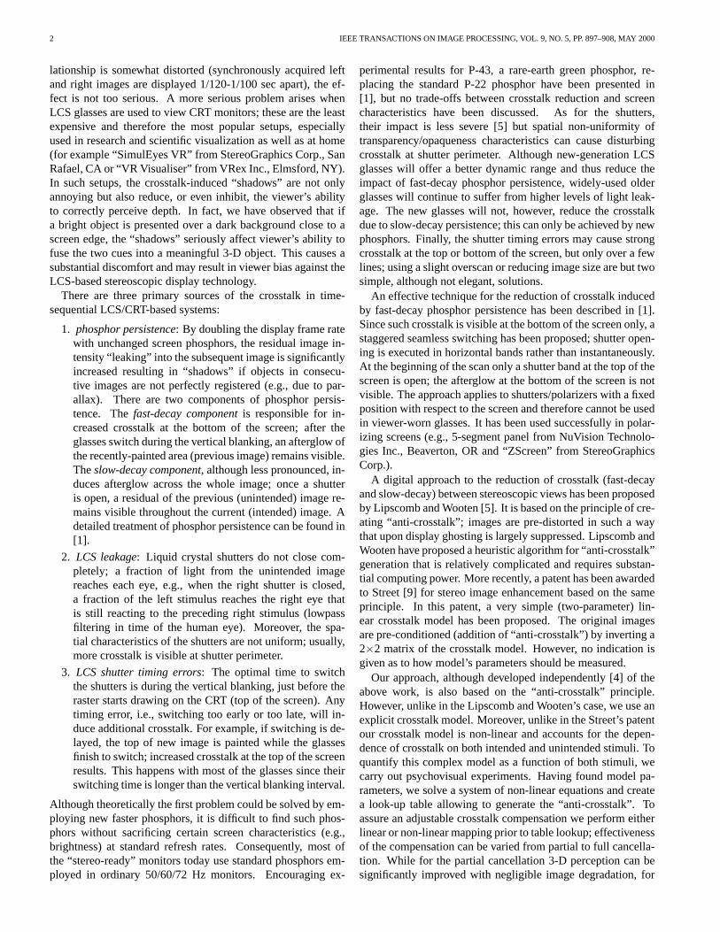
lationship is somewhat distorted (synchronously acquired leftand right images are displayed 1/120-1/100 sec apart), the ef-fect is not too serious. A more serious problem arises whenLCS glasses are used to view CRT monitors; these are the leastexpensive and therefore the most popular setups, especiallyused in research and scientific visualization as well as at home(for example “SimulEyes VR” from StereoGraphics Corp., SanRafael, CA or “VR Visualiser” from VRex Inc., Elmsford, NY).In such setups, the crosstalk-induced “shadows” are not onlyannoying but also reduce, or even inhibit, the viewer’s abilityto correctly perceive depth. In fact, we have observed that ifa bright object is presented over a dark background close to ascreen edge, the “shadows” seriously affect viewer’s ability tofuse the two cues into a meaningful 3-D object. This causes asubstantial discomfort and may result in viewer bias against theLCS-based stereoscopic display technology.
There are three primary sources of the crosstalk in time-sequential LCS/CRT-based systems:
1. phosphor persistence: By doubling the display frame ratewith unchanged screen phosphors, the residual image in-tensity “leaking” into the subsequent image is significantlyincreased resulting in “shadows” if objects in consecu-tive images are not perfectly registered (e.g., due to par-allax). There are two components of phosphor persis-tence. The fast-decay component is responsible for in-creased crosstalk at the bottom of the screen; after theglasses switch during the vertical blanking, an afterglow ofthe recently-painted area (previous image) remains visible.The slow-decay component, although less pronounced, in-duces afterglow across the whole image; once a shutteris open, a residual of the previous (unintended) image re-mains visible throughout the current (intended) image. Adetailed treatment of phosphor persistence can be found in[1].
2. LCS leakage: Liquid crystal shutters do not close com-pletely; a fraction of light from the unintended imagereaches each eye, e.g., when the right shutter is closed,a fraction of the left stimulus reaches the right eye thatis still reacting to the preceding right stimulus (lowpassfiltering in time of the human eye). Moreover, the spa-tial characteristics of the shutters are not uniform; usually,more crosstalk is visible at shutter perimeter.
3. LCS shutter timing errors: The optimal time to switchthe shutters is during the vertical blanking, just before theraster starts drawing on the CRT (top of the screen). Anytiming error, i.e., switching too early or too late, will in-duce additional crosstalk. For example, if switching is de-layed, the top of new image is painted while the glassesfinish to switch; increased crosstalk at the top of the screenresults. This happens with most of the glasses since theirswitching time is longer than the vertical blanking interval.
Although theoretically the first problem could be solved by em-ploying new faster phosphors, it is difficult to find such phos-phors without sacrificing certain screen characteristics (e.g.,brightness) at standard refresh rates. Consequently, most ofthe “stereo-ready” monitors today use standard phosphors em-ployed in ordinary 50/60/72 Hz monitors. Encouraging ex-
perimental results for P-43, a rare-earth green phosphor, re-placing the standard P-22 phosphor have been presented in[1], but no trade-offs between crosstalk reduction and screencharacteristics have been discussed. As for the shutters,their impact is less severe [5] but spatial non-uniformity oftransparency/opaqueness characteristics can cause disturbingcrosstalk at shutter perimeter. Although new-generation LCSglasses will offer a better dynamic range and thus reduce theimpact of fast-decay phosphor persistence, widely-used olderglasses will continue to suffer from higher levels of light leak-age. The new glasses will not, however, reduce the crosstalkdue to slow-decay persistence; this can only be achieved by newphosphors. Finally, the shutter timing errors may cause strongcrosstalk at the top or bottom of the screen, but only over a fewlines; using a slight overscan or reducing image size are but twosimple, although not elegant, solutions.
An effective technique for the reduction of crosstalk inducedby fast-decay phosphor persistence has been described in [1].Since such crosstalk is visible at the bottom of the screen only, astaggered seamless switching has been proposed; shutter open-ing is executed in horizontal bands rather than instantaneously.At the beginning of the scan only a shutter band at the top of thescreen is open; the afterglow at the bottom of the screen is notvisible. The approach applies to shutters/polarizers with a fixedposition with respect to the screen and therefore cannot be usedin viewer-worn glasses. It has been used successfully in polar-izing screens (e.g., 5-segment panel from NuVision Technolo-gies Inc., Beaverton, OR and “ZScreen” from StereoGraphicsCorp.).
A digital approach to the reduction of crosstalk (fast-decayand slow-decay) between stereoscopic views has been proposedby Lipscomb and Wooten [5]. It is based on the principle of cre-ating “anti-crosstalk”; images are pre-distorted in such a waythat upon display ghosting is largely suppressed. Lipscomb andWooten have proposed a heuristic algorithm for “anti-crosstalk”generation that is relatively complicated and requires substan-tial computing power. More recently, a patent has been awardedto Street [9] for stereo image enhancement based on the sameprinciple. In this patent, a very simple (two-parameter) lin-ear crosstalk model has been proposed. The original imagesare pre-conditioned (addition of “anti-crosstalk”) by inverting a2×2 matrix of the crosstalk model. However, no indication isgiven as to how model’s parameters should be measured.
Our approach, although developed independently [4] of theabove work, is also based on the “anti-crosstalk” principle.However, unlike in the Lipscomb and Wooten’s case, we use anexplicit crosstalk model. Moreover, unlike in the Street’s patentour crosstalk model is non-linear and accounts for the depen-dence of crosstalk on both intended and unintended stimuli. Toquantify this complex model as a function of both stimuli, wecarry out psychovisual experiments. Having found model pa-rameters, we solve a system of non-linear equations and createa look-up table allowing to generate the “anti-crosstalk”. Toassure an adjustable crosstalk compensation we perform eitherlinear or non-linear mapping prior to table lookup; effectivenessof the compensation can be varied from partial to full cancella-tion. While for the partial cancellation 3-D perception can besignificantly improved with negligible image degradation, for

KONRAD ET AL.: CANCELLATION OF IMAGE CROSSTALK 3
full cancellation the perception is effortless at the cost of re-duced contrast and increased brightness of the image. Overall,viewers’ response has been very encouraging with claims ofimproved 3-D perception and reduced visual fatigue. The pro-posed algorithm is very fast as it only requires scaling and tablelook-up, and can be easily implemented in real time by verymodest hardware. In fact, it can be implemented today directlyon advanced graphics boards.
The paper is organized as follows. Section II presents thecrosstalk model used, while Section III describes how parame-ters of that model were measured. In Section IV an algorithmfor crosstalk cancellation is developed and in Section V experi-mental results are discussed. Section VI discusses issues relatedto the implementation and possible applications.
II. CROSSTALK MODEL
We assume a simple crosstalk model: in addition to the in-tended stimulus, a fraction of the unintended stimulus is per-ceived by each eye. Initial experiments, however, quicklyproved that the fraction perceived also depends on the intendedstimulus. For example, similar magnitude of ghosting may beperceived in both of the following scenarios:
1. high-brightness unintended stimulus superposed overhigh-brightness intended stimulus,
2. low-brightness unintended stimulus superposed over low-brightness intended stimulus.
Thus, our model depends on both intended and unintendedstimuli, and can be expressed as follows:
f ′(x) = f(x) + φ(g(x), f(x)), (1)
where x denotes pixel coordinate, f ′ is the image perceived bythe eye, f is the intended (displayed) image for a given eye andg is the unintended image (source of crosstalk). φ is a crosstalkfunction that quantifies the amount of crosstalk seen by an eyeas a function of unintended and intended stimuli. Since ourmodel applies only to a particular pixel and ignores the pointspread function of the CRT and LCS, we will omit the depen-dence of f on x in the sequel.
For the left (fl) and right (fr) images, the joint model can bewritten as follows:
f ′l = fl + φ(fr, fl),f ′r = fr + φ(fl, fr),
(2)
where fl, fr denote the original images (as seen on a regularmonoscopic display) and f ′
l , f′
r are images with crosstalk (asperceived by a viewer on a stereoscopic display compliant withmodel (1)).
The model (2) is scalar and is applicable to black-and-whiteimages. To extend the model to color images, three crosstalkfunctions must be applied in a suitable color space. Since videomonitors use additive color reproduction based on R, G and Bprimary colors, we apply the model in the R-G-B color space;each of the three crosstalk functions φR, φG, φB characterizesone channel. The three-channel model is appealing since in atypical monitorR,G andB phosphors have different character-istics; for example, the green phosphor’s persistence is longerthan that of the red and blue phosphors.
As we mentioned before, our approach is based on the cre-ation of anti-crosstalk, and is similar to the method proposedby Lipscomb and Wooten [5]. There are fundamental differ-ences between the two models, however. Whereas we eval-uate the crosstalk function φ in a psychovisual experiment(Section III), the approach taken in [5] to assess the correc-tion needed is heuristic, especially regarding the special treat-ment of thin vertical lines and left edges of bright objects. Onthe other hand, Lipscomb and Wooten allow for a vertically-variable anti-crosstalk to compensate for shutter timing errors(top of the screen) and fast-decay phosphor persistence (bottomof the screen). Once quantified, this variability could be eas-ily incorporated into our algorithm; in our stereo setup therewas no extra crosstalk at the top and bottom of the screen dueto black horizontal bands above and below the image (reducedvertical size).
III. PSYCHOVISUAL CHARACTERIZATION OF THE
CROSSTALK
To evaluate the crosstalk functions φR, φG, φB we have car-ried out a psychovisual experiment for R, G, B componentsindependently. The experiment calibrated our display systemconsisting of CrystalEyes LCS glasses from StereoGraphicsCorp. (including GDC-3 graphics display controller) and GDM-20E01T multi-sync monitor from Sony Corp. Although theo-retically a similar experiment would need to be performed forother setups, an application of psychovisual measurements forthe Sony monitor to crosstalk cancellation on a NEC monitorworked very well (Section V).
’lf fadj
gray cover
Fig. 1. Experimental setup for the psychovisual characterization of thecrosstalk function for the left eye. fadj is a viewer-adjustable stimulus intendedfor the left eye whereas f ′
lis a combination of the stimulus fl intended for the
left eye and of fr that is unintended for the left eye (right-eye stimulus). Seetext for details.
The experiment was performed as follows (Fig. 1):
1. to minimize the impact of screen and shutter non-uniformity on measurements only the central part of thescreen was visible (20cm horizontally by 10cm vertically)and viewers were asked to view this area only through thecenter of the shutters; the visible area was vertically di-vided into adjacent (no separation) left and right halves(Fig. 1),
4 IEEE TRANSACTIONS ON IMAGE PROCESSING, VOL. 9, NO. 5, PP. 897–908, MAY 2000
2. the right eye was excluded from the experiment (the rightshutter was permanently covered); we assumed that theresults would be valid for the right eye as well,
3. only spatially- and temporally-constant primary-colorstimuli (R, G and B) were used,
4. in the left half of the screen, a viewer-adjustable stimulusfadj intended for the left eye was shown; no unintendedstimulus was shown in that half (fr=0),
5. in the right half of the screen, both a stimulus fl in-tended for the left eye and a stimulus fr unintended for theleft eye (right-eye stimulus) were presented, thus inducingcrosstalk,
6. the values of fl and fr were operator-selected and theviewer was asked to match the two halves of the screenby adjusting fadj .
Clearly, the experimental results should be valid only for thecentral part of the screen viewed through the center of theshutters. We have disregarded screen non-uniformity since inLCS-based systems it plays a secondary role to shutter non-uniformity that cannot be easily corrected since glasses do nothave fixed relative position with respect to the screen. Per-haps, the only possibility is an improvement of shutter unifor-mity during manufacturing. Although the proposed approachto crosstalk cancellation is optimized for the center of the shut-ters, in general it is through this center that the viewer will fix-ate. Since for the viewer the fixation point belongs to the mostimportant area of the image (at a given time instant), optimalcrosstalk suppression should dominate. This is based on the as-sumption that to fixate the viewer rotates his head, perhaps aninvalid assumption for small screens.
Mathematically, the description of the experimental setupcan be written as follows:
left half: fadj + φ(0, fadj) = fadj + 0 = fadj
right half: fl + φ(fr, fl) = f ′l
where φ(0, fadj)=0 since no unintended stimulus was presentin the left half of the screen. Once the viewer has matched thetwo parts of the screen, i.e., f ′
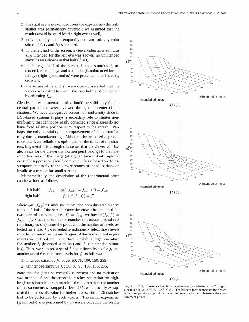
l = fadj , we have φ(fr, fl) =fadj − fl. Since the number of matches to execute is equal to 3(3 primary colors) times the product of the number of levels se-lected for fl and fr, we needed to judiciously select those levelsin order to minimize viewer fatigue. After some initial exper-iments we realized that the surface φ exhibits larger curvaturefor smaller fl (intended stimulus) and fr (unintended stimu-lus). Thus, we selected a set of 7 nonuniform levels for fl andanother set of 6 nonuniform levels for fr as follows:
1. intended stimulus fl: 0, 25, 50, 75, 100, 150, 235,
2. unintended stimulus fr: 30, 60, 95, 135, 185, 235.
Note that for fr=0 no crosstalk is present and no evaluationwas needed. Since the crosstalk reaches saturation for high-brightness intended or unintended stimuli, to reduce the numberof measurements we stopped at level 235; we bilinearly extrap-olated the crosstalk value for higher levels. Still, 126 matcheshad to be performed by each viewer. The initial experiment(green only) was performed by 5 viewers but since the results
0
60
135185
235
050
100150
235
0
10
20
30
40
50
60
70
80
90
100
Unintended stimulusIntended stimulus
φ R
(a) φR
0
60
135185
235
050
100150
235
0
10
20
30
40
50
60
70
80
90
100
Unintended stimulusIntended stimulus
φ G
(b) φG
0
60
135185
235
050
100150
235
0
10
20
30
40
50
60
70
80
90
100
Unintended stimulusIntended stimulus
φ B
(c) φB
Fig. 2. R,G,B crosstalk functions psychovisually evaluated on a 7×6 grid(see text): (a) φR; (b) φG; and (c) φB . The bilinear facet representation shownis but one possible approximation of the crosstalk function between the mea-surement points.
KONRAD ET AL.: CANCELLATION OF IMAGE CROSSTALK 5
were very similar (often identical) we used only 3 viewers inthe complete set of tests. During the experiments we confirmedthat the liquid crystal shutters do not have spatially-uniformtransparency; intensity leakage was stronger at the LCS perime-ter (clover leaf pattern). This non-uniformity was very strik-ing when examined with spatio-temporally constant stimuli, butless obvious for complex images.
Crosstalk functions for each primary color computed as anaverage of the three measurements (3 subjects) are shown inFig. 2; the results apply only to the central part of the screenviewed through the center of the shutters. The crosstalk func-tions for green and blue primaries are very similar (the am-plitude of φG is slightly higher). The φR crosstalk function,however, attains lower amplitude and its surface is more curvedthan that of φG and φB . Similar observation regarding smallercrosstalk in the red component has been made elsewhere [5].Note that for large values of the intended stimulus, the crosstalkis very small regardless of the unintended stimulus; any objectover bright background induces little crosstalk. For small val-ues of the intended stimulus, however, the crosstalk gets largerfor larger values of the unintended stimulus; over a dark back-ground, the brighter the object the stronger the crosstalk.
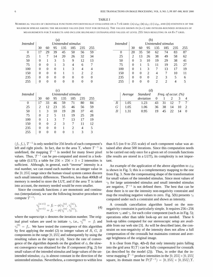
Table I lists numerical values of the crosstalk functions; val-ues shown are integer-rounded averages of measurements for3 subjects and include extrapolated values at level 255. Non-rounded values as well as other information can be found onour web site [3]. The same table shows average, standard de-viation and frequency of occurrence for the maximum spread(difference between maximum and minimum) among the mea-sured values for the three viewers for each of the 42 data pointsand for each component (R, G and B).
IV. ALGORITHM FOR CROSSTALK ELIMINATION
Equations (2) describe a continuous mapping T : R2→ R2
that transforms (fl, fr) into (f ′l , f′
r). Let the domain and rangeof T be D(T ) andR(T ), respectively.
Since the crosstalk φ is a continuous function that has beenmeasured in a psychovisual experiment over a 7 × 6 grid, amodel is needed to interpolate the value of the crosstalk for anyunintended and intended stimuli. We have chosen the bilinearinterpolation for its simplicity and for the small spatial supportof its kernel, particularly important because of the small num-ber of measurement points. We have also tested a least-squaresapproximation by a 2-D polynomial [4]. Although a 4-th orderpolynomial (15 coefficients) resulted in a maximum approxi-mation error of less than 2, it was not monotonic over D(T );φ increased for high-brightness intended stimuli. At the sametime, a lower-order polynomial resulted in a much higher ap-proximation error.
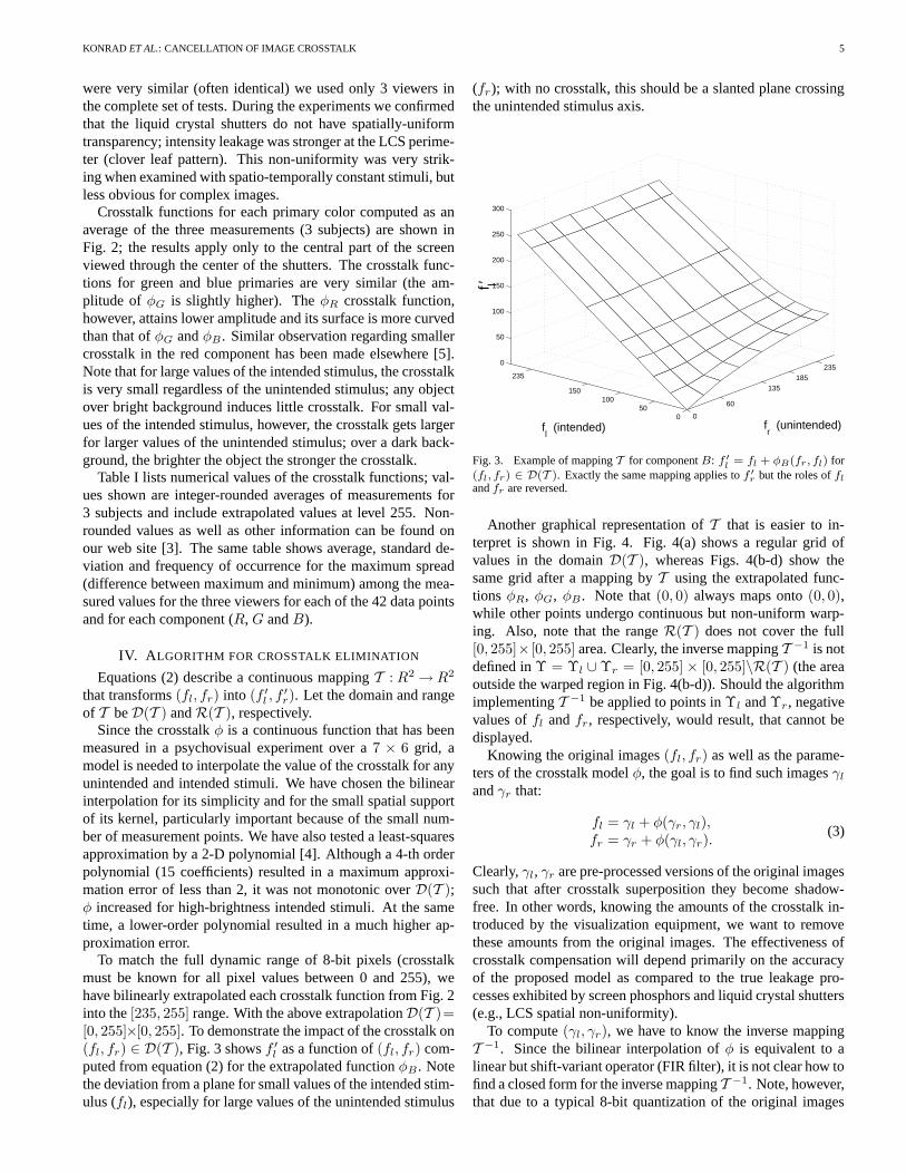
To match the full dynamic range of 8-bit pixels (crosstalkmust be known for all pixel values between 0 and 255), wehave bilinearly extrapolated each crosstalk function from Fig. 2into the [235, 255] range. With the above extrapolationD(T )=[0, 255]×[0, 255]. To demonstrate the impact of the crosstalk on(fl, fr) ∈ D(T ), Fig. 3 shows f ′
l as a function of (fl, fr) com-puted from equation (2) for the extrapolated function φB . Notethe deviation from a plane for small values of the intended stim-ulus (fl), especially for large values of the unintended stimulus
(fr); with no crosstalk, this should be a slanted plane crossingthe unintended stimulus axis.
0
60
135185
235
050
100150
235
0
50
100
150
200
250
300
fr (unintended) f
l (intended)
f l′
Fig. 3. Example of mapping T for component B: f ′
l= fl + φB(fr, fl) for
(fl, fr) ∈ D(T ). Exactly the same mapping applies to f ′
r but the roles of fl
and fr are reversed.
Another graphical representation of T that is easier to in-terpret is shown in Fig. 4. Fig. 4(a) shows a regular grid ofvalues in the domain D(T ), whereas Figs. 4(b-d) show thesame grid after a mapping by T using the extrapolated func-tions φR, φG, φB . Note that (0, 0) always maps onto (0, 0),while other points undergo continuous but non-uniform warp-ing. Also, note that the range R(T ) does not cover the full[0, 255]× [0, 255] area. Clearly, the inverse mapping T −1 is notdefined in Υ = Υl ∪ Υr = [0, 255] × [0, 255]\R(T ) (the areaoutside the warped region in Fig. 4(b-d)). Should the algorithmimplementing T −1 be applied to points in Υl and Υr, negativevalues of fl and fr, respectively, would result, that cannot bedisplayed.
Knowing the original images (fl, fr) as well as the parame-ters of the crosstalk model φ, the goal is to find such images γl
and γr that:
fl = γl + φ(γr, γl),fr = γr + φ(γl, γr).
(3)
Clearly, γl, γr are pre-processed versions of the original imagessuch that after crosstalk superposition they become shadow-free. In other words, knowing the amounts of the crosstalk in-troduced by the visualization equipment, we want to removethese amounts from the original images. The effectiveness ofcrosstalk compensation will depend primarily on the accuracyof the proposed model as compared to the true leakage pro-cesses exhibited by screen phosphors and liquid crystal shutters(e.g., LCS spatial non-uniformity).
To compute (γl, γr), we have to know the inverse mappingT −1. Since the bilinear interpolation of φ is equivalent to alinear but shift-variant operator (FIR filter), it is not clear how tofind a closed form for the inverse mapping T −1. Note, however,that due to a typical 8-bit quantization of the original images
6 IEEE TRANSACTIONS ON IMAGE PROCESSING, VOL. 9, NO. 5, PP. 897–908, MAY 2000
TABLE INUMERICAL VALUES OF CROSSTALK FUNCTIONS PSYCHOVISUALLY EVALUATED ON A 7×6 GRID: (A) φR ; (B) φG ; (C) φB , AND (D) STATISTICS OF THE
MAXIMUM SPREAD AMONG THE MEASURED VALUES (SEE TEXT FOR DETAILS). THE VALUES SHOWN IN (A-C) ARE INTEGER-ROUNDED AVERAGES OF
MEASUREMENTS FOR 3 SUBJECTS AND INCLUDE BILINEARLY EXTRAPOLATED VALUES AT LEVEL 255 THUS RESULTING IN AN 8×7 GRID.
(a)Intended Unintended stimulus
30 60 95 135 185 235 2550 17 29 39 45 50 56 59
25 1 7 14 20 26 32 3450 0 1 3 5 9 12 1375 0 0 1 3 4 6 7
100 0 0 0 1 3 4 4150 0 0 0 1 1 2 2235 0 0 0 0 0 0 0255 0 0 0 0 0 0 0
(b)Intended Unintended stimulus
30 60 95 135 185 235 2550 20 35 50 62 74 83 87
25 2 13 26 38 49 58 6250 0 3 10 19 29 38 4175 0 1 5 11 19 25 27
100 0 1 3 7 13 17 19150 0 0 2 4 7 10 11235 0 0 0 2 3 5 6255 0 0 0 2 2 4 5
(c)Intended Unintended stimulus
30 60 95 135 185 235 2550 17 33 46 59 71 80 84
25 2 12 23 35 46 56 5950 1 3 10 19 28 37 4175 0 2 5 11 19 25 28
100 0 1 3 7 13 17 19150 0 0 2 3 7 11 12235 0 0 0 1 2 4 5255 0 0 0 0 1 3 3
(d)Average Standard Freq. of occur. (%)
deviation 0 1 2 3 4R 1.05 1.23 43 31 12 7 7G 1.05 1.06 36 38 14 10 2B 1.31 0.95 19 45 22 14 0
(fl, fr), T −1 is only needed for 256 levels of each component’sleft and right pixels. In fact, due to the area Υ, where T −1 isundefined, the mapping T −1 is needed for many fewer pixelvalues. Thus, T −1 can be pre-computed and stored in a look-up table (LUT); a table for 256 × 256 × 3 × 2 intensities issufficient. Although, in general, each “inverse” intensity is areal number, we can round each number to an integer value inthe [0, 255] range since the human visual system cannot discernsuch small intensity differences. Therefore, less than 400kB ofmemory is needed to store the LUT, and if the area Υ is takeninto account, the memory needed would be even smaller.
Since the crosstalk functions φ are monotonic and continu-ous (interpolation), we use the following iterative procedure tocompute T −1:
γ(n+1)l = fl − φ(γ
(n)r , γ
(n)l ),
γ(n+1)r = fr − φ(γ
(n)l , γ
(n)r ),
(4)
where the superscript n denotes the iteration number. The orig-inal pixel values are used to initiate γ, i.e., γ(0)
l = fl and
γ(0)r = fr. We have tested the convergence of this algorithm
by first applying the model (2) to integer values of R, G, Bcomponents in the range [0, 255] and subsequently by using theresulting values as the input to (4). Since the rate of conver-gence of the algorithm depends on the gradient of φ, the slow-est convergence was obtained for the R component (Fig. 2) forsmall values of the intended stimulus and large values of the un-intended stimulus; φR is almost constant in the direction of theunintended stimulus. Nevertheless, a convergence to within less
than 0.5 (on 0 to 255 scale) of each component value was at-tained after about 500 iterations. Since this computation needsto be carried out only once for a given set of crosstalk functions(the results are stored in a LUT), its complexity is not impor-tant.
An example of the application of the above algorithm to φB
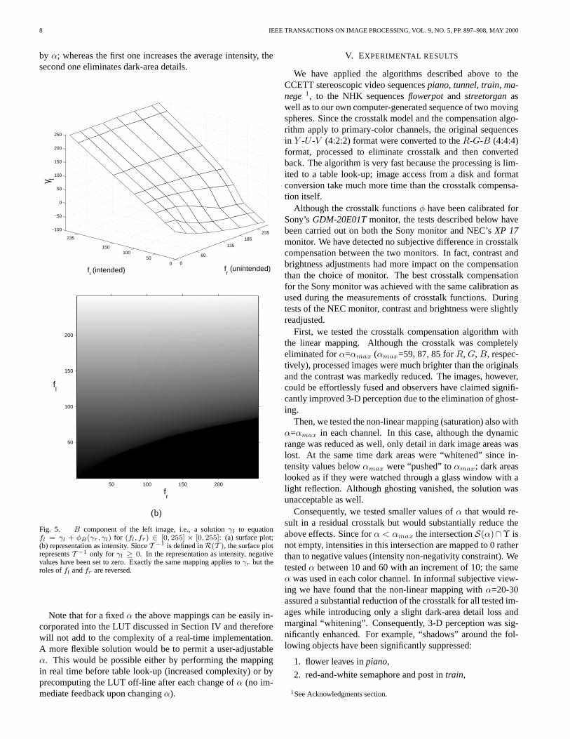
is shown in Fig. 5; this is a complementary mapping to the onefrom Fig. 3. Note the compensating shape of the transformationfor small values of the intended stimulus. Since most values ofγl for large unintended stimulus and small intended stimulusare negative, T −1 is not defined there. The best that can bedone there is to use the intensity non-negativity constraint andmap the resulting negative values to zero. Fig. 5(b) presents γl
computed under such a constraint and shown as intensity.
A crosstalk cancellation algorithm based on the non-negativity constraint is particularly simple. It requires 256×256matrices γl and γr for each color component (such as in Fig. 5);operations other than table look-up are not needed. These 6look-up tables computed for our stereoscopic setup are avail-able from our web site [3]. As will be described later, the con-straint on non-negativity of the intensity does not allow a fullcompensation of the crosstalk but maintains contrast and aver-age brightness of the original image.
It is clear from Figs. 4(b-d) that only intensity pairs fallinginto the grid area R(T ) can be fully compensated for crosstalk(as described by the model (2)). Thus, in order that the in-verse mapping T −1 produce intensities in the [0, 255]× [0, 255]square, its domain must be D(T −1) = [0, 255] × [0, 255]\Υ.

KONRAD ET AL.: CANCELLATION OF IMAGE CROSSTALK 7
0 50 100 150 200 250
0
50
100
150
200
250
fl
f r
(a)
0 50 100 150 200 250
0
50
100
150
200
250
fl′
f r′
ϒl
ϒr
αmax
=59
(b)
0 50 100 150 200 250
0
50
100
150
200
250
fl′
f r′
ϒl
ϒr
αmax
=87
(c)
0 50 100 150 200 250
0
50
100
150
200
250
fl′
f r′
ϒl
ϒr
αmax
=85
(d)
Fig. 4. (a) Regular grid of intensities (fl, fr) ∈ D(T ) with levels 0, 51, 102, 153, 204, 255, and the same grid after mapping by T (equation (2)) for (a) φR; (b)φG; (c) φB . See text for the meaning of Υl and Υr . Dotted lines show S(αmax).
However, the original images fl and fr will certainly containintensities outside the grid area, i.e., in Υ. To assure a fullcrosstalk cancellation, intensities in Υ must be mapped ontoD(T −1) before the compensation.
Let T (0, fr) = (ψ(f ′r), f′
r) and T (fl, 0) = (f ′l , ψ(f ′l )).These are boundary curves of the transformed grid in Figs. 4(b-d) that neighbor Υl and Υr, respectively. Also, let S(α) be avariable-size square in the (f ′
l , f′
r) plane defined by [α, 255] ×[α, 255], where 0 ≤ α ≤ αmax and αmax=ψ(255) for each pri-mary color (dotted square in Fig. 4). For α=αmax full crosstalkcompensation is assured since the square S is included in thegrid area, i.e., S(αmax) ⊂ R(T ).
We have investigated pre-processing via linear and non-
linear mappings defined as follows:
1. linear mapping [0, 255]× [0, 255]→ S(α):
fl ← α+ fl
255− α
255,
fr ← α+ fr
255− α
255,
2. non-linear mapping [0, 255]× [0, 255]→ S(α):
fl ← max (fl, α),
fr ← max (fr, α).
Clearly, both mappings reduce the dynamic range of the image
8 IEEE TRANSACTIONS ON IMAGE PROCESSING, VOL. 9, NO. 5, PP. 897–908, MAY 2000
by α; whereas the first one increases the average intensity, thesecond one eliminates dark-area details.
0
60
135185
235
050
100150
235
−100
−50
0
50
100
150
200
250
fr (unintended) f
l (intended)
γl
(a)
fl
fr
50 100 150 200
200
150
100
50
(b)
Fig. 5. B component of the left image, i.e., a solution γl to equationfl = γl + φB(γr, γl) for (fl, fr) ∈ [0, 255] × [0, 255]: (a) surface plot;(b) representation as intensity. Since T −1 is defined in R(T ), the surface plotrepresents T −1 only for γl ≥ 0. In the representation as intensity, negativevalues have been set to zero. Exactly the same mapping applies to γr but theroles of fl and fr are reversed.
Note that for a fixed α the above mappings can be easily in-corporated into the LUT discussed in Section IV and thereforewill not add to the complexity of a real-time implementation.A more flexible solution would be to permit a user-adjustableα. This would be possible either by performing the mappingin real time before table look-up (increased complexity) or byprecomputing the LUT off-line after each change of α (no im-mediate feedback upon changing α).
V. EXPERIMENTAL RESULTS
We have applied the algorithms described above to theCCETT stereoscopic video sequences piano, tunnel, train, ma-nege 1, to the NHK sequences flowerpot and streetorgan aswell as to our own computer-generated sequence of two movingspheres. Since the crosstalk model and the compensation algo-rithm apply to primary-color channels, the original sequencesin Y -U -V (4:2:2) format were converted to the R-G-B (4:4:4)format, processed to eliminate crosstalk and then convertedback. The algorithm is very fast because the processing is lim-ited to a table look-up; image access from a disk and formatconversion take much more time than the crosstalk compensa-tion itself.
Although the crosstalk functions φ have been calibrated forSony’s GDM-20E01T monitor, the tests described below havebeen carried out on both the Sony monitor and NEC’s XP 17monitor. We have detected no subjective difference in crosstalkcompensation between the two monitors. In fact, contrast andbrightness adjustments had more impact on the compensationthan the choice of monitor. The best crosstalk compensationfor the Sony monitor was achieved with the same calibration asused during the measurements of crosstalk functions. Duringtests of the NEC monitor, contrast and brightness were slightlyreadjusted.
First, we tested the crosstalk compensation algorithm withthe linear mapping. Although the crosstalk was completelyeliminated for α=αmax (αmax=59, 87, 85 for R, G, B, respec-tively), processed images were much brighter than the originalsand the contrast was markedly reduced. The images, however,could be effortlessly fused and observers have claimed signifi-cantly improved 3-D perception due to the elimination of ghost-ing.
Then, we tested the non-linear mapping (saturation) also withα=αmax in each channel. In this case, although the dynamicrange was reduced as well, only detail in dark image areas waslost. At the same time dark areas were “whitened” since in-tensity values below αmax were “pushed” to αmax; dark areaslooked as if they were watched through a glass window with alight reflection. Although ghosting vanished, the solution wasunacceptable as well.
Consequently, we tested smaller values of α that would re-sult in a residual crosstalk but would substantially reduce theabove effects. Since for α < αmax the intersection S(α)∩Υ isnot empty, intensities in this intersection are mapped to 0 ratherthan to negative values (intensity non-negativity constraint). Wetested α between 10 and 60 with an increment of 10; the sameα was used in each color channel. In informal subjective view-ing we have found that the non-linear mapping with α=20-30assured a substantial reduction of the crosstalk for all tested im-ages while introducing only a slight dark-area detail loss andmarginal “whitening”. Consequently, 3-D perception was sig-nificantly enhanced. For example, “shadows” around the fol-lowing objects have been significantly suppressed:
1. flower leaves in piano,
2. red-and-white semaphore and post in train,
1See Acknowledgments section.
KONRAD ET AL.: CANCELLATION OF IMAGE CROSSTALK 9
3. red-and-white post, ladder and white helmets in tunnel,
4. bus and bus stop in manege,
5. girl’s hat in streetorgan.
The improvement in 3-D perception was particularly strikingfor the red-and-white semaphore in train and the red-and-whitepost in tunnel, both near picture edge. The original and someprocessed images from the above list are available for inspec-tion on our web site [3]).
We have found that for α=20-30, the linear mapping giveseven better crosstalk suppression. Although the contrast wasslightly reduced and the average image intensity increased no-ticeably, the crosstalk was almost fully compensated unlike inthe case of the non-linear mapping (for the same α). The 3-Dperception improved dramatically and observers were very pos-itive about the subjective value of the improvement. In fact, inall tested images only objects causing extreme contrast, suchas the white helmet in the tunnel next to the locomotive in tun-nel and the white features on the black door in streetorgan, re-quire a much higher α (about 60) to be fully compensated. Thepenalty paid is the increased image brightness due to scaling –an unacceptable solution in quality-oriented applications.
Finally, we have tested the crosstalk compensation algorithmwith the non-negativity constraint only (no pre-processing).With this approach although only partial crosstalk compensa-tion was achieved, the 3-D perception was significantly im-proved. The cancellation was only slightly inferior to the onewith non-linear mapping but it was clearly worse than for theone with linear mapping, both with α=20-30. In addition to thefact that the method preserves image fidelity (only slight loss ofdark-area detail) while largely suppressing the crosstalk, it alsohas the lowest computational complexity of all the algorithmstested. The approach may be of interest in applications wereimage fidelity is of primary concern.
To visually demonstrate how the compensation algorithm af-fects images, Figs. 6 and 7 show a small luminance windowfrom field #0 of sequences piano and train, respectively. In pi-ano, silver-white leaves are presented over a blue background,whereas in train a red-and-white semaphore is shown over agray sky. In the middle rows, original images with crosstalksuperposed digitally according to model (1) are shown; noteslight ghosting on either side of the leaves. We have comparedthese images with the original images from Figs. 6(a-b) and7(a-b) viewed through LC shutters using one eye at a time. Forexample, for the left eye, left monoscopic image with super-posed model-based crosstalk was compared, by instantaneousswitching, with the left original image that exhibited naturalcrosstalk due to leakage from the right image of the stereopair.In informal tests, the two images were judged almost identical.This test has confirmed the validity of our model (1). We havedrawn another interesting conclusion from the above test. Sincethe crosstalk-prone areas in the tested images were close to im-age boundaries (leaves in piano and semaphore in train) andsince the model was judged accurate, we can conclude that theassumption about spatial uniformity of the screen is not detri-mental to the model and therefore to the crosstalk cancellationitself.
In the bottom row are shown images from Figs. 6(a-b) and
7(a-b) after the non-linear mapping with α=30. Note the darkimprints in the background of either window corresponding tobright leaves and white semaphore sections in the other win-dow. It is exactly in these areas that the LCS leakage and phos-phor persistence will get superposed onto the original image toprovide a crosstalk-free perception. An extensive set of results(linear and non-linear mapping, various α’s, various images)can be found on our web site [3].
There is an additional benefit of the above compensation.The overall brightness of each crosstalk-compensated imageis reduced compared to the corresponding original image ifviewed monoscopically; the same compensation principle re-sulting from equation (3) applies everywhere in the image.Therefore, compensated images viewed stereoscopically havea brightness corresponding to the monoscopic image, whereasuncompensated images are slightly brighter in the stereo modedue to the cross-view leak. This effect, however, is not seriousenough to call for a compensation by itself.
VI. IMPLEMENTATION AND APPLICATIONS
We see possible applications for the proposed algorithm instereoscopic visualization systems using a digital image for-mat. An immediate application would be in computer-basedstereo setups with substantial CPU power, e.g., powerful PCsor workstations; images would be pre-processed in software be-fore shipping to a graphics board. This solution may requiresuitable conversions if the available data is not in the R-G-Bformat. Although for video sequences the needed CPU powerwould be substantial, still stereo images could be pre-computedand only then displayed. Also, user-adjustable α would requireextra CPU cycles.
Alternatively, the data can be processed in hardware on agraphics board after conversion to the R-G-B format but be-fore D/A conversion; this is the only option for setups void ofCPU power. No inverse format conversion would be needed; a400kB memory and a simple scaling or “max” operator on theboard would suffice. Although the least expensive PC graphicsboards do not satisfy these requirements, more advanced boardsare very close to meeting them. With such boards, a real-timeadjustment of α could become possible as well.
It is important to note that the proposed crosstalk compensa-tion algorithm can and should be adapted to a particular appli-cation by selecting a suitable type of mapping and its parameterα. Both should be user-selectable in real-time for a maximumvisual comfort; for example, a reference sequence could be usedto perform adaptation to both eyewear/screen setup and user’stolerance of crosstalk.
Based on our experience we believe that if fidelity to the orig-inal data is critical, no mapping should be applied (only non-negativity constraint) thus resulting in a partial crosstalk elimi-nation. If a slight departure from the original (dark areas only)can be tolerated, then non-linear mapping with α=20-30 shouldbe used; we believe that the incurred dark detail loss should notbe objectionable to most viewers. However, if the benefits ofeffortless 3-D fusion and undisturbed perception of depth out-weigh image contrast, we suggest to use the linear mappingwith α=20-30; higher values should be used only in extreme

10 IEEE TRANSACTIONS ON IMAGE PROCESSING, VOL. 9, NO. 5, PP. 897–908, MAY 2000
(a) (b)
(c) (d)
(e) (f)
Fig. 6. Luminance of the original (a) left and (b) right fields #0 from piano sequence, (c-d) the same images with crosstalk superposed digitally according tomodel (2), and (e-f) original images compensated for crosstalk using non-linear mapping with α=30. Since the sequence is 2:1 interlaced, vertical interpolationby 2 was applied to maintain correct aspect ratio.
cases. We believe that for 3-D TV, 3-D games or other quality-oriented stereoscopic applications the first two scenarios apply;no or almost unnoticeable change in contrast/brightness is in-troduced. However, for such applications as 3-D visualization,microscopy/ultrasound or remote guidance, we believe that thelatter solution incurring brighter images is appropriate since thecorrect perception of depth is at least as important there as thefaithfulness of color or intensity.
VII. SUMMARY AND CONCLUSIONS
We presented a unique approach to the enhancement of 3-Dperception in time-sequential displays of stereoscopic images
using LCS glasses. We proposed a simple crosstalk model, weevaluated its parameters in a psychovisual experiment, we val-idated model’s accuracy and we proposed a computationally-efficient algorithm for crosstalk elimination. We demonstratedthat a simple version of the algorithm using only the non-negativity constraint assures negligible distortion but only par-tial crosstalk compensation. By introducing a pre-processingstage in the form of a non-linear or linear mapping, we im-proved the crosstalk cancellation capacity at the cost of reducedcontrast and increased image brightness. Since both mappingsare controlled by a single parameter, a continuous adjustmentbetween partial compensation/negligible degradation and full

KONRAD ET AL.: CANCELLATION OF IMAGE CROSSTALK 11
(a) (b)
(c) (d)
(e) (f)
Fig. 7. Luminance of the original (a) left and (b) right fields #0 from train sequence, (c-d) the same images with crosstalk superposed digitally according tomodel (2), and (e-f) original images compensated for crosstalk using non-linear mapping with α=30. Since the sequence is 2:1 interlaced, vertical interpolationby 2 was applied to maintain correct aspect ratio.
compensation/significant degradation can be performed by theuser. The adjustment would depend on user preference in termsof the maximum visual comfort and on stereoscopic applica-tion used. The proposed approach can be extended to handlethe additional top- and bottom-screen crosstalk present in manysystems; however additional measurements would have to beperformed. We believe that the algorithm presented can be im-plemented today on advanced graphics boards, and thereforecan be incorporated into various stereo applications such as 3-D microscopy, remote guidance or 3-D computer games.
ACKNOWLEDGMENTS
We would like to thank Dr. Bruno Choquet of the CCETT,Rennes, France and the RACE DISTIMA project of the Eu-ropean Community for providing us with the stereoscopic se-quences used in this work. We would also like to thank Dr. Al-bert Gołembiowski and Mr. Anthony Mancini for their help inpreparing some of the results.
REFERENCES
[1] P. Bos, “Time sequential stereoscopic displays: The contribution of phos-phor persistence to the “ghost” image intensity,” in Proc. ITEC’91 AnnualConf., Three-Dimensional Image Tech., (H. Kusaka, ed.), pp. 603–606,July 1991.
12 IEEE TRANSACTIONS ON IMAGE PROCESSING, VOL. 9, NO. 5, PP. 897–908, MAY 2000
[2] D. Ezra, G. Woodgate, B. Omar, N. Holliman, J. Harrold, and L. Shapiro,“New autostereoscopic display system,” in Proc. SPIE (Stereoscopic Dis-plays and Virtual Reality Systems II), vol. 2409, pp. 31–40, Feb. 1995.
[3] http://www.inrs-telecom.uquebec.ca/users/viscom/english/publications.[4] B. Lacotte, “Elimination of keystone and crosstalk effects in stereoscopic
video,” Tech. Rep. 95-31, INRS-Telecommunications, Dec. 1995.[5] J. Lipscomb and W. Wooten, “Reducing crosstalk between stereoscopic
views,” in Proc. SPIE Stereoscopic Displays and Virtual Reality Systems,vol. 2177, pp. 92–96, Feb. 1994.
[6] L. Lipton, “Compatibility issues and selection devices for stereoscopictelevision,” Signal Process., Image Commun., vol. 4, pp. 15–20, 1991.
[7] L. Lipton, “True stereoscopic television: 3D-TV is feasible and striking,”Advanced Imaging, pp. 28–30, July 1994.
[8] I. Sexton, T. Bardsley, and A. Bhoopal, “Errors in depth,” in Int. Workshopon Stereoscopic and 3D Imaging, pp. 235–242, Sept. 1995.
[9] G. Street, “Method and apparatus for image enhancement.” EuropeanPatent No. 819359, Feb. 1999.
[10] W. Tam and L. Stelmach, “Stereo depth perception in a sample of youngtelevision viewers,” in Int. Workshop on Stereoscopic and 3D Imaging,(Santorini, Greece), pp. 149–156, Sept. 1995.