OPERATOR'S MANUAL Model - Optic-Handel Fragstein
144
AUTO REF/KERATO/TONOMETER OPERATOR ’ S MANUAL Model
-
Upload
khangminh22 -
Category
Documents
-
view
1 -
download
0
Transcript of OPERATOR'S MANUAL Model - Optic-Handel Fragstein

AUTO REF/KERATO/TONOMETER
OPERATOR’S MANUAL
Model

NIDEK CO., LTD. : 34-14, Maehama, Hiroishi-cho, Gamagori, Aichi 443-0038, Japan(Manufacturer) Telephone: (81-533) 67-6611
Facsimile: (81-533) 67-6610NIDEK CO., LTD : 3F Sumitomo Fudosan Hongo Bldg., 3-22-5, Hongo,(Tokyo Office) Bunkyo-Ku, Tokyo 113-0033, Japan
Telephone: (81-3) 5844-2641Facsimile: (81-3) 5844-2642
NIDEK INCORPORATED : 47651 Westinghouse Drive, Fremont, California 94539, U. S. A.(United States Agent) Telephone: (510) 226-5700
Facsimile: (510) 226-5750NIDEK SOCIETE ANONYME : Europarc 13, rue Auguste Perret, 94042 CRETEIL, France(EU Authorized Representative) Telephone: (01) 49 80 97 97
Facsimile: (01) 49 80 32 08August 2007
15601-P902BPrinted in JAPAN

I
:
Use this device properly and safely.
"CAUTION! Federal Law (US) restricts this device to sale by or on the order of a physician ora properly licensed practitioner."
Safety precautions
BEFORE USE, READ THIS MANUAL.
This operator’s manual contains information necessary for the operation of the NIDEKAUTO REF/KERATO/TONOMETER Model TONOREF II. This manual includes theoperating procedures, safety precautions, and specifications.
This manual is necessary for proper use. Especially, the safety precautions and operatingprocedures must be thoroughly understood prior to operation of the device.
Keep this manual handy to verify use whenever necessary.
The device complies with ISO 10342 (Ophthalmic instruments-Eye Refractometers). Thedioptric powers are indicated with reference wavelength λd = 587.56 nm.
There are no user-serviceable parts inside the device except printer paper.
If you encounter any problems or have questions about the device, please contact NIDEKor your authorized distributor.
In this manual, signal words are used to designate the degree or level of safety alerting. The defi-nitions are as follows.
WARNING • Indicates a potentially hazardous situation which, if not avoided, could result in death orserious injury.
CAUTION • Indicates a potentially hazardous situation which, if not avoided, may result in minor ormoderate injury or property damage accident.
Even situations indicated by “ CAUTION” may result in serious injury under certain conditions.Safety precautions must be strictly followed at all times.

II
:
Use precautions
Before Use
CAUTION• Do not use the device for other than the intended purpose.NIDEK is not responsible for accidents or malfunctions caused by misuse.
• Be sure to read the manual prior to operation of the device to understand the safetyprecautions and operating procedures thoroughly.
Using the device for purposes other than specified in this manual may cause unex-pected malfunctions and/or adverse events.
• Never modify nor touch the internal structure of the device.Electric shock or malfunction may result.
• Install the device in an environment that meets the following conditions. The followingconditions must be maintained during use.
Use conditionsTemperature: +10 to +35°CHumidity: 30 to 75% (Non-condensing)Pressure: 800 to 1060 hPaA dust-free locationA place with little external lightA level and stable surface free from vibration and shockIf the device is not installed and used under the above conditions, the reliability of mea-sured results is impaired, and malfunction may result. In addition, there is a possibility ofinjury if the device receives shock and falls down.
• Install the device in an environment where no contaminants such as corrosive gas,acid, and salt are contained in the air.
Corrosion or malfunction of the device may result.
• Avoid installing the device where it is exposed to direct air-conditioning flow.Changes in temperature may result in condensation inside the device or adverselyaffect measurements.
• Be sure to use a wall outlet which meets the power specification requirements.If the line voltage is too high or too low, the device may not perform properly. Malfunc-tion or fire may occur.
• Connect the power plug to a ground outlet. Or connect a grounding wire to a groundterminal.
Electric shock or fire may occur in the event of device malfunction or power leakage.
• Completely insert the power plug into the outlet as far as the prongs will go.Fire may occur if the device is used with a loose connection.
• Never use a table tap or extension cable to supply the device with power.The electrical safety may be lowered.
III
:
CAUTION• Do not use a power cord other than the one supplied. Also do not connect thesupplied power cord to any other device.
Failure or fire may result.
• Do not place heavy objects on the power cord.The damaged power cord may cause fire or electric shock.
• Before connecting cables to the device, turn the device off and disconnect the powercord from an outlet.
Malfunction may result.
• Before carrying the device, put the device into the packing mode and lock the mainbody to the base with the locking lever.
An accidental movement of the measuring unit during transportation may result in mal-function.
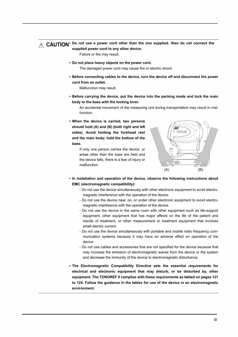
• When the device is carried, two personsshould hold (A) and (B) (both right and leftsides). Avoid holding the forehead restand the main body; hold the bottom of thebase.
If only one person carries the device, orareas other than the base are held andthe device falls, there is a fear of injury ormalfunction.
• In installation and operation of the device, observe the following instructions aboutEMC (electromagnetic compatibility):
- Do not use the device simultaneously with other electronic equipment to avoid electro-magnetic interference with the operation of the device.
- Do not use the device near, on, or under other electronic equipment to avoid electro-magnetic interference with the operation of the device.
- Do not use the device in the same room with other equipment such as life-supportequipment, other equipment that has major affects on the life of the patient andresults of treatment, or other measurement or treatment equipment that involvessmall electric current.
- Do not use the device simultaneously with portable and mobile radio frequency com-munication systems because it may have an adverse effect on operation of thedevice.
- Do not use cables and accessories that are not specified for the device because thatmay increase the emission of electromagnetic waves from the device or the systemand decrease the immunity of the device to electromagnetic disturbance.
• The Electromagnetic Compatibility Directive sets the essential requirements forelectrical and electronic equipment that may disturb, or be disturbed by, otherequipment. The TONOREF II complies with these requirements as tabled on pages 121to 124. Follow the guidance in the tables for use of the device in an electromagneticenvironment.
(A) (B)

IV
:
During Use
WARNING • Before starting NT measurement, set the safety stopper for each patient to prevent theair nozzle from touching the patient’s eye.
Contact between the air nozzle and the eye may damage the cornea.
CAUTION• Before use, perform visual and operation checks. If abnormal conditions areencountered, stop using the device.
If the device is used under abnormal conditions, intended results may not occur. Alsounexpected malfunctions or health hazards may occur due to improper measurement.
• Be sure to connect an interface cable, checking the symbols of input (IN: ) and
output (OUT: ).
Data transmission may not be performed properly.
• Take care not to catch hands or fingers in moving parts (measurement part and chinrest). Be sure to give this caution to patients.
Hands or fingers may be pinched and may result in injury.
• When measuring, caution patients not to touch the NT measurement part.When switching from NT measurement to R/K measurement, the air nozzle recessesand the shutter closes at which time fingers may be caught in the shutter. (In this case,the cover stops immediately and does not result in injury.)
• Every time before treating a different patient, clean the patient’s contact area (chinrest and forehead rest) using disinfectant alcohol.
If chinrest paper is used, remove one piece for each patient.
• Keep the measuring window free of fingerprints and dust.The measurement accuracy may decrease substantially.
• In the event of smoke or strange odors, immediately turn off the device anddisconnect the power plug from the outlet. After you are sure that the smoke hasstopped, then contact NIDEK or your authorized distributor.
Usage of the device under such abnormal conditions may cause fire or electric shock.In case of fire, use a dry chemical (ABC) extinguisher to extinguish the fire.
• Immediately replace the power cord if the internal wires are exposed, the device turnson or off when the power cord is moved, or the cord and/or plug are too hot to be heldwith hands.
This may result in electric shock or fire.In the event of malfunction, disconnect the power cord from the wall outlet. Never touchthe inside of the device and contact NIDEK or your authorized distributor.
• Never press the LCD display with a hard object such as a ball-point pen. Keepmagnetic objects away from the LCD display.
The device may be damaged.
• Do not operate the LCD display with wet hands.Water seeping into the device may result in failure of the device.
V
:
CAUTION• There may be a few constantly-lit, missing, or dead pixels in your LCD which are acharacteristic of the LCD. This does not represent failure of the LCD; continuouslyuse the display.
• This device has been tested and found to comply with the limits for medical devicesto the IEC 60601-1-2: 2001, and Medical Device Directive 93/42/EEC.These limits are designed to provide reasonable protection against harmfulinterference in a standard medical installation.This device generates, uses and can radiate radio frequency energy and, if notinstalled and used in accordance with the instructions, may cause harmfulinterference to other devices in the vicinity.However, there is no guarantee that interference will not occur in a particularinstallation. If this device does cause harmful interference to other devices, which canbe determined by turning the device off and on, the user is encouraged to try tocorrect the interference by one or more of the following measures:If this device does cause harmful interference to other devices, which can bedetermined by turning the device off and on, the user is encouraged to try to correctthe interference by one or more of the following measures:
Reorient or relocate the receiving device.Increase the separation between the devices.Connect the device to an outlet on a circuit different from that to which the otherdevice(s) are connected.Consult the manufacturer or field service technician for help.
• The device is Class A (CISPR11 classification). It is allowed in domesticestablishments when used under jurisdiction of a health care professional.
• Never use the device with cables or accessories other than the designated ones.Malfunction caused by improper electromagnetic compatibility (EMC) characteristicsmay result.
• Never use portable or mobile radio frequency (RF) devices in the vicinity of thisdevice.
These devices may adversely affect medical electrical equipment and malfunction mayresult.
• The device uses thermal paper for printer. When saving the printings, make a copy ofit.
Thermal paper may become difficult to read due to aged deterioration.
• This device uses a heat-sensitive printer paper. To keep the printed data for a longperiod of time, make copies of the printouts.
The paper degrades over time and the printed data may become illegible.

VI
:
CAUTION• Information on the avoidance of overexposure to potentially hazardous opticalradiation (ISO 15004: 1997)
Spectrally weighted photochemical radiances LB and LA give a measure of the potentialthat exists for a beam of light to cause photochemical hazard to the retina. LB gives themeasure for eyes in which the crystalline lens is in place. LA gives this measure eitherfor eyes in which the crystalline lens has been removed (aphakes) and has not beenreplaced by a UV-blocking lens or for the eyes of very young children.The value stated for this ophthalmic device gives a measure of hazard potential whenthe device is operated at maximum intensity and maximum aperture. The values of LA
or LB for the TONOREF II are sufficiently low as shown on the following page.The retinal exposure dose for a photochemical hazard is a product of the radiance andthe exposure time. For instance, at a radiance level of 0.5 mW/(cm2 sr), 480 min irradi-ation of the dilated (8 mm diameter) pupil would cause the retinal exposure dose level toattain the recommended exposure limit. If the value of radiance were reduced to 0.1mW/(cm2 sr), five times that time (i.e. 2400 min) would be needed to reach the recom-mended limit. The recommended exposure dose is based on calculations arising fromthe American Conference of Governmental Industrial Hygienists (ACGIH) - ThresholdLimit Values for Chemical Substances and Physical Agents (1995 - 1996 edition).The following page shows the graph of spectrum output for the TONOREF II. Patients willbe at low risk of acute optical radiation with the TONOREF II. However, it is recommendedthat the intensity of light directed into the patient’s eye be limited to the minimum levelwhich is necessary for diagnosis. The total of the retinal exposure dose must be carefullywatched for infants, aphakes and persons with diseased eyes who are at greater riskwhen other ophthalmic devices with a high level of radiance are used in conjunction.
• Spectrum output of all light source during AR/KM measurement (maximum light intensity)
* The wavelength 1000 to 1100 is calculated and plotted according to the wavelength charac-teristic data of the infrared LED used.
• Spectrum irradiance
LA: Spectrally weighted photochemical aphakic source radianceLB: Spectrally weighted photochemical phakic source radiance
Irrad
ianc
e (μ
W/c
m2 )
Wavelength (nm)
LA (mW/cm2/sr) 305 - 700 nm 0.0027
LB (mW/cm2/sr) 380 - 700 nm 0.0003

VII
:
After Use
CAUTION• When the device is not in use, turn off the power switch and put the dust cover overthe device.
If not, dust may affect the measurement accuracy.
• Do not yank the power cord to disconnect it from a wall outlet but hold the plug.This can damage the metal core of the cord and may result in fire, short circuit or elec-tric shock.
• Occasionally clean the prongs of the main plug with a dry cloth.If dust settles between the prongs, the dust will collect moisture, and short circuit or firemay occur.
• If the device will not be used for a long time, disconnect the power cord from the walloutlet.
Fire may occur.
• Maintain the surrounding temperature and humidity at the following ranges duringtransportation and storage of the device.
Environmental conditions:Temperature: –10ºC to +55ºCHumidity: 10 to 95% (non-condensing)Pressure: 700 hPa to 1060 hPaNo large amount of dust is contained in the air.A place not exposed to direct sunlight
• To transport the device, use the special packing materials to protect from shock andimpact.
Excessive vibration or impact may cause device malfunction.
• When transporting, set the mode to Packing mode and pack the main body in theoriginal packing material with the fixing lever unlocked.
It may result in failure when excessive vibration and shock are applied.

VIII
:
Maintenance
Disposal
CAUTION• Only service technicians properly trained by NIDEK can repair the device.NIDEK is not responsible for any accidents resulted from improper servicing.
• When performing maintenance work, secure sufficient maintenance space.Maintenance work in an insufficient space may result in injury.
• When the device is sent back to NIDEK for repair or maintenance, wipe the surfaces(especially, the area where patients contact) of the device with a clean clothdampened with ethyl alcohol for disinfection.
• Contact NIDEK or your authorized distributor to check whether the device needsmeasurement accuracy calibration if the AR-measured results are substantiallydifferent from subjectively measured results.
• To maintain the performance, ask NIDEK to conduct yearly inspection.Inspection items: Calibration of measurement value
Equipment component operation check
CAUTION• Follow local governing ordinances and recycling plans regarding disposal orrecycling of device components. The device contains the circuit board with a lithiumbattery mounted. Because the disposal method of lithium batteries varies accordingto the local government, follow the local governing ordinates and recycling planswhen disposing of the circuit board with the lithium battery.
It is recommended to commission the disposal to a designated industrial waste disposalcontractor.
• When disposing of packing materials, sort them by material and follow localgoverning ordinances and recycling plans.

IX
:
Patient environment
The patient environment represents a space where there is a possibility of direct contact between thepatient or the operator and third person.When another type of device is used in the patient environment, use a device that complies with IEC60601-1. If the devices that do not comply with IEC 60601-1 are used, it is necessary to use an isolat-ing transformer as a power supply or to connect the devices to additional protective grounding.
Radius of 1.5 m
1.5 m 1.5 m
2.5 m

Table of Contents
X
1. BEFORE USE . . . . . . . . . . . . . . . . . . . . . . . . . . . . . . . . . . . 11.1 Outline of the device. . . . . . . . . . . . . . . . . . . . . . . . . . . . . . . . . . . . . . . . . . . . . . . . . . . .1
1.2 Indications for Use . . . . . . . . . . . . . . . . . . . . . . . . . . . . . . . . . . . . . . . . . . . . . . . . . . . . .2
1.3 Principles . . . . . . . . . . . . . . . . . . . . . . . . . . . . . . . . . . . . . . . . . . . . . . . . . . . . . . . . . . . . . .3
1.4 Device Description . . . . . . . . . . . . . . . . . . . . . . . . . . . . . . . . . . . . . . . . . . . . . . . . . . . . .4
1.5 Measurement Screen Description . . . . . . . . . . . . . . . . . . . . . . . . . . . . . . . . . . . . . . .91.5.1 R/K measurement screen . . . . . . . . . . . . . . . . . . . . . . . . . . . . . . . . . . . . . . . . . . . . .91.5.2 NT measurement screen . . . . . . . . . . . . . . . . . . . . . . . . . . . . . . . . . . . . . . . . . . . .14
1.6 Labels and Indications on the Device . . . . . . . . . . . . . . . . . . . . . . . . . . . . . . . . . . .16
1.7 Checking Contents . . . . . . . . . . . . . . . . . . . . . . . . . . . . . . . . . . . . . . . . . . . . . . . . . . . .18
1.8 Before First Use . . . . . . . . . . . . . . . . . . . . . . . . . . . . . . . . . . . . . . . . . . . . . . . . . . . . . . .19
2. OPERATING PROCEDURES . . . . . . . . . . . . . . . . . . . . . . 232.1 Operation Flow. . . . . . . . . . . . . . . . . . . . . . . . . . . . . . . . . . . . . . . . . . . . . . . . . . . . . . . .23
2.2 Preparation for Measurement . . . . . . . . . . . . . . . . . . . . . . . . . . . . . . . . . . . . . . . . . .242.2.1 Measuring window check for soiling and puffed air pressure check during startup 292.2.2 Switching between R/K measurement and NT measurement . . . . . . . . . . . . . . . .31
2.3 Finishing the Measurements . . . . . . . . . . . . . . . . . . . . . . . . . . . . . . . . . . . . . . . . . . .332.3.1 Normal shutoff. . . . . . . . . . . . . . . . . . . . . . . . . . . . . . . . . . . . . . . . . . . . . . . . . . . . .332.3.2 Shutoff before transporting the device . . . . . . . . . . . . . . . . . . . . . . . . . . . . . . . . . .33
2.4 Selecting the Mode . . . . . . . . . . . . . . . . . . . . . . . . . . . . . . . . . . . . . . . . . . . . . . . . . . . .352.4.1 Switching to manual mode . . . . . . . . . . . . . . . . . . . . . . . . . . . . . . . . . . . . . . . . . . .372.4.2 Sleep mode. . . . . . . . . . . . . . . . . . . . . . . . . . . . . . . . . . . . . . . . . . . . . . . . . . . . . . .38
2.5 AR (refractive error) and KM (corneal curvature radius) Measurements . . .392.5.1 AR (refractive error) and KM (corneal curvature radius) measurements:
AR/KM measurement mode . . . . . . . . . . . . . . . . . . . . . . . . . . . . . . . . . . . . . . . . . .392.5.2 AR (refractive error) Measurement: AR Measurement Mode . . . . . . . . . . . . . . . . .492.5.3 KM (corneal curvature radius) Measurement:
KM Measurement Mode . . . . . . . . . . . . . . . . . . . . . . . . . . . . . . . . . . . . . . . . . . . . .512.5.4 CS (Corneal Size) Measurement . . . . . . . . . . . . . . . . . . . . . . . . . . . . . . . . . . . . . .532.5.5 PS (Pupil Size) Measurement. . . . . . . . . . . . . . . . . . . . . . . . . . . . . . . . . . . . . . . . .552.5.6 PD (Pupillary Distance) Measurement . . . . . . . . . . . . . . . . . . . . . . . . . . . . . . . . . .572.5.7 Measuring Hard Contact Lenses . . . . . . . . . . . . . . . . . . . . . . . . . . . . . . . . . . . . . .59
2.6 NT (Tonometry) Measurement: NT Mode . . . . . . . . . . . . . . . . . . . . . . . . . . . . . . .612.6.1 Eyelid detection mode. . . . . . . . . . . . . . . . . . . . . . . . . . . . . . . . . . . . . . . . . . . . . . .70
2.7 Printing . . . . . . . . . . . . . . . . . . . . . . . . . . . . . . . . . . . . . . . . . . . . . . . . . . . . . . . . . . . . . . .712.7.1 Printing measured data. . . . . . . . . . . . . . . . . . . . . . . . . . . . . . . . . . . . . . . . . . . . . .712.7.2 Eyeprint. . . . . . . . . . . . . . . . . . . . . . . . . . . . . . . . . . . . . . . . . . . . . . . . . . . . . . . . . .742.7.3 Printing parameter settings . . . . . . . . . . . . . . . . . . . . . . . . . . . . . . . . . . . . . . . . . . .75

XI
:
2.8 Parameter Settings. . . . . . . . . . . . . . . . . . . . . . . . . . . . . . . . . . . . . . . . . . . . . . . . . . . . 762.8.1 Parameter tables . . . . . . . . . . . . . . . . . . . . . . . . . . . . . . . . . . . . . . . . . . . . . . . . . . 792.8.2 Setting the date and time . . . . . . . . . . . . . . . . . . . . . . . . . . . . . . . . . . . . . . . . . . . . 892.8.3 Entering comments. . . . . . . . . . . . . . . . . . . . . . . . . . . . . . . . . . . . . . . . . . . . . . . . . 91
3. OPERATION WHEN PERIPHERAL DEVICES ARE CONNECTED . . . . . . . . . . . . . . . . . . . . . . . . . . . . . . . . . . 933.1 Connecting to the NIDEK Motorized Refractor (RT) or Computer . . . . . . . . . 93
3.1.1 Outline . . . . . . . . . . . . . . . . . . . . . . . . . . . . . . . . . . . . . . . . . . . . . . . . . . . . . . . . . . 933.1.2 Connecting procedure . . . . . . . . . . . . . . . . . . . . . . . . . . . . . . . . . . . . . . . . . . . . . . 943.1.3 Operating procedure. . . . . . . . . . . . . . . . . . . . . . . . . . . . . . . . . . . . . . . . . . . . . . . . 94
3.2 Connecting to the NIDEK Auto Lensmeter (LM) . . . . . . . . . . . . . . . . . . . . . . . . . 953.2.1 Outline . . . . . . . . . . . . . . . . . . . . . . . . . . . . . . . . . . . . . . . . . . . . . . . . . . . . . . . . . . 953.2.2 Connecting procedure . . . . . . . . . . . . . . . . . . . . . . . . . . . . . . . . . . . . . . . . . . . . . . 953.2.3 Operating procedure. . . . . . . . . . . . . . . . . . . . . . . . . . . . . . . . . . . . . . . . . . . . . . . . 96
3.3 Connecting to the Eye Care Card System. . . . . . . . . . . . . . . . . . . . . . . . . . . . . . . 973.3.1 Outline . . . . . . . . . . . . . . . . . . . . . . . . . . . . . . . . . . . . . . . . . . . . . . . . . . . . . . . . . . 973.3.2 Method of connection . . . . . . . . . . . . . . . . . . . . . . . . . . . . . . . . . . . . . . . . . . . . . . . 973.3.3 Transferring data with the EyeCa-RW . . . . . . . . . . . . . . . . . . . . . . . . . . . . . . . . . . 983.3.4 Erasing data on the Eye Care card . . . . . . . . . . . . . . . . . . . . . . . . . . . . . . . . . . . . 99
4. MAINTENANCE . . . . . . . . . . . . . . . . . . . . . . . . . . . . . . . 1014.1 Troubleshooting. . . . . . . . . . . . . . . . . . . . . . . . . . . . . . . . . . . . . . . . . . . . . . . . . . . . . . 101
4.2 Error Messages and Countermeasures . . . . . . . . . . . . . . . . . . . . . . . . . . . . . . . . 103
4.3 Replacing Printer Paper . . . . . . . . . . . . . . . . . . . . . . . . . . . . . . . . . . . . . . . . . . . . . . 106
4.4 Fixing Chinrest Paper . . . . . . . . . . . . . . . . . . . . . . . . . . . . . . . . . . . . . . . . . . . . . . . . 108
4.5 Checking the AR/KM Measurement Accuracy . . . . . . . . . . . . . . . . . . . . . . . . . . 109
4.6 Cleaning. . . . . . . . . . . . . . . . . . . . . . . . . . . . . . . . . . . . . . . . . . . . . . . . . . . . . . . . . . . . . 1114.6.1 Cleaning the measuring window. . . . . . . . . . . . . . . . . . . . . . . . . . . . . . . . . . . . . . 1114.6.2 Cleaning the air nozzle. . . . . . . . . . . . . . . . . . . . . . . . . . . . . . . . . . . . . . . . . . . . . 1134.6.3 Cleaning the printer . . . . . . . . . . . . . . . . . . . . . . . . . . . . . . . . . . . . . . . . . . . . . . . 114
4.7 List of Replacement Parts . . . . . . . . . . . . . . . . . . . . . . . . . . . . . . . . . . . . . . . . . . . . 114
5. SPECIFICATIONS AND ACCESSORIES . . . . . . . . . . . 1155.1 Classifications . . . . . . . . . . . . . . . . . . . . . . . . . . . . . . . . . . . . . . . . . . . . . . . . . . . . . . . 115
5.2 Safety Features . . . . . . . . . . . . . . . . . . . . . . . . . . . . . . . . . . . . . . . . . . . . . . . . . . . . . . 116
5.3 Specifications . . . . . . . . . . . . . . . . . . . . . . . . . . . . . . . . . . . . . . . . . . . . . . . . . . . . . . . . 117

:
XII
5.4 Standard Configuration . . . . . . . . . . . . . . . . . . . . . . . . . . . . . . . . . . . . . . . . . . . . . . . 1205.4.1 Standard accessories . . . . . . . . . . . . . . . . . . . . . . . . . . . . . . . . . . . . . . . . . . . . . . 1205.4.2 Optional accessories . . . . . . . . . . . . . . . . . . . . . . . . . . . . . . . . . . . . . . . . . . . . . . 120
6. EMC (ELECTROMAGNETIC COMPATIBILITY) . . . . . . 121
7. GLOSSARY . . . . . . . . . . . . . . . . . . . . . . . . . . . . . . . . . . 125
8. INDEX . . . . . . . . . . . . . . . . . . . . . . . . . . . . . . . . . . . . . . . 129

1
1
1. BEFORE USE
1.1 Outline of the device
AUTO REF/KERATO/TONOMETER Model TONOREF II is designed to singly perform objectiverefraction, corneal shape measurement, and non-contact tonometry measurement by incorporating astandard auto ref/keratometer and non-contact tonometer into one unit.The objective refraction function measures spherical powers, cylindrical powers and cylinder axis. Thecorneal shape measurement function measures the radius of corneal curvature (corneal refractivepowers), the direction of the steepest meridian, and the amount of corneal astigmatism. The non-contact tonometry function measures the intraocular pressure without contacting the eye.Refraction is mainly performed as a reference for lens prescription for correction of visual acuity usingspectacles and contact lenses.The corneal curvature radius measurement is performed mainly for the following purposes:
• To prescribe lenses for correction of visual acuity using contact lenses
• To determine the power of intraocular lenses to be implanted after cataract surgery
• To conduct postoperative follow-up of corneal shapeTonometry is performed for the early detection of glaucoma, and for preoperative examination andpostoperative care in ophthalmology.
This device is an integral type with a main body mounted on a base.A chinrest is mounted on the base on the patient’s side.An LCD panel, control buttons, joystick and a printer are attached on the main body to conduct align-ment and perform operations. Inside the device are units for performing AR/KM and NT measure-ments, which can be operated by simply pressing a button/switch. In addition to the above, the device also offers the following features:
• A space-saving concept that allows AR/KM and NT measurements to be performed by asingle device which saves space and eliminates the need for the patient to move betweentwo devices.
• An auto-tracking mechanism is provided. The device automatically controls the up-and-down and back-and-forth movements for alignment and focusing.
• An auto-shooting function is provided. Measurements take place automatically when thedevice is best aligned and in focus.
• An APC function that measures the intraocular pressure with the minimum necessary pres-sure of puffed air.
• A motorized up-and-down chinrest allows the operator to adjust the height of the chinrest.
• A built-in RS-232C interface allows data export to computers etc.

2
BEFORE USE: Indications for Use
1.2 Indications for Use
The AUTO REF/KERATO/TONOMETER TONOREF II is a medical apparatus which performs mea-surement of the refractive errors of the eye, corneal radius of curvature and intraocular pressure.

3
BEFORE USE: Principles
1
1.3 Principles
1. Objective refractionFine measurement beams are projected on the fundus of the patient’s eye by a projectingoptical system and then computation is performed by capturing the reflected beams as aring image to measure the refractive errors (SPH, CYL, AXIS) of the patient’s eye.
2. Corneal curvature radius measurementFour near-infrared rays area projected onto the cornea and the ray reflected by the cornea isdetected. From the detected signals, the corneal curvature radius (refractive power) and thedirection of the steepest meridian are measured.
3. Measurement of intraocular pressure (NT measurement)Based on the Imbert-Fick principle (W = Pt × A), the intraocular pressure is calculated bydividing the amount of air pressure into the area of applanated surface.
The device increases the air pressure puffed onto the cornea in proportion to time. Theshape of the cornea changes gradually in the order of convex surface → applanated surface→ concave surface. This change is optically detected and the device calculates the timerequired to make the pressed area flat after air is puffed on it. The air pressure used to makethe cornea flat is calculated by time, and finally the intraocular pressure is obtained.
APC (Automatic Puff Control) function
The intraocular pressure measurement is performed with the air pressure as low as possible. Whenthe measurement range is set to “APC 40” or “APC 60”, in the first measurement, the automaticshut-off function, which stops puffing air as soon as the light reflected from the cornea is detected,activates in order to eliminate excessive puffing.
In subsequent measurements, the APC function activates to perform the measurement with theminimum air pressure based on the former measurement data.
As the patient's eye is protected from excessive air pressure, discomfort of the patient can bedecreased and continuous measurement can be performed smoothly.
4
BEFORE USE: Device Description
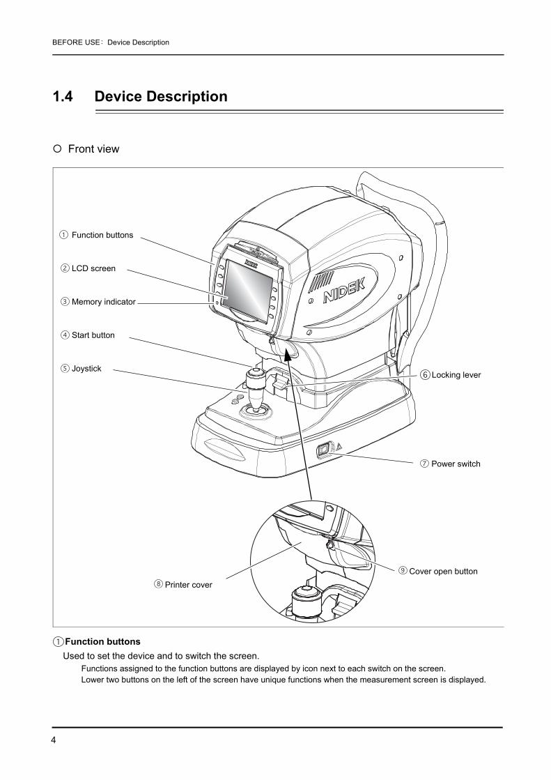
1.4 Device Description
Front view
Function buttonsUsed to set the device and to switch the screen.
Functions assigned to the function buttons are displayed by icon next to each switch on the screen.Lower two buttons on the left of the screen have unique functions when the measurement screen is displayed.
Function buttons
LCD screen
Memory indicator
Start button
JoystickLocking lever
Power switch
Printer coverCover open button

5
BEFORE USE: Device Description
1
• CLR button ( )Used to clear the measured data.
When the CLR button is pressed for about a second, all the measured data is erased.
• Print button ( )When this button is pressed while the memory indicator is lit, measured results are printed out.
If this button is pressed when the memory indicator is turned off, the printer paper is fed.
LCD screen5.7-inch color LCD screen. The LCD screen panel pops out when the lower portion of the panel is pulled toward you.
When operating the device in an upright position, tilt the panel so that the indications on the screen are clear.The panel is reset to its original position by magnet.
Memory indicatorIndicates that measured data is being stored in memory.
Start buttonWhen the start button is pressed, the measurement takes place regardless of the alignment and focusing status of the device.
JoystickUsed for alignment and focusing.
Tilt the joystick to the right and left for alignment. Turn the joystick for alignment in the up and down directions. For focusing, push the joystick forward and pull it backward.
Locking leverUsed to fix the main body to the base unit.
To lock the main body, press the locking lever down.
Power switchUsed to turn on or off the power to the device.
Printer coverInside is the printer equipped with the auto cutter located. Open the printer cover for replacing printer paper by pressing the cover open button.
Cover open buttonTo open the printer cover, press the button.
ON Measured data is stored in the internal memory.
OFF Measured data is not stored in the internal memory.
Blinking Sleep mode

6
BEFORE USE: Device Description
Rear view
Forehead restDuring measurements, the patient’s forehead should be gently placed over the forehead rest.
Clean the forehead rest for each patient.
Air nozzleAir is puffed out of the nozzle of the NT measuring unit.
In this operator’s manual, the area containing the observation window around the air nozzle is referred to as the air nozzle. Just before the AR/KM measurement, the air nozzle is automatically stored in the device.
Measuring windowPerforms R/K measurement.
Check the window for soiling before R/K measurement.
ChinrestClean the chinrest for each patient.
Patient sensorThe patient sensor detects whether the patient is seated in front of the device.
The sensor, while detecting the patient, assumes that the patient’s chin is placed on the chinrest. The chinrest is not moved up and down to the origin for safety.
Eye level markerUsed as a guide for the patient's eye level during measurements.
The height of the chinrest should be adjusted so that the center level of the patient’s eye almost aligns with this line.
Eyelid detection LEDs
Forehead rest
LED for Corneal Illumination
Air nozzle
Measuring window
Chinrest
Patient sensor
Eye level marker
Chinrest up/down buttons
Safety stopper
PD window
7
BEFORE USE: Device Description
1
Chinrest up/down buttons ( , )Move up or down the chinrest.
Safety stopperUsed to provide a safety space so that the air nozzle does not touch the patient’s eye.
Change the position of the stopper for each patient to keep the proper amount of the space for safety.While pressing the safety stopper, “RTN TO ORG” blinks on the screen, and the measuring unit automatically returns to the origin in the right, left, back and forth directions.
PD windowLEDs that detect the PD value are located.
• Materials composed of the parts that contact the patient during measurement are asfollows:
Forehead rest: ElastomerChinrest: ABS resin

8
BEFORE USE: Device Description
Bottom view
Power inletUsed to connect the detachable power cord.
RS-232C connectorConnect an interface cable to send/receive the measured data to/from a diagnostic device or such.Target device
RT-2100 series, RT-5100LM-970, LM-990/990A, LM-1000/1000P, LM-1200
Connecting the lensmeter to the side and the RT-2100/RT-5100 to the side allows data transmission to the connected refractor via the TONOREF II.
USB-A connectorConnect a USB flash memory when the software needs to be upgraded.
Do not connect any USB device other than flash memory.The upgrade is performed by NIDEK service personnel.
*1 Accessory equipment connected to the analog and digital interfaces must be certified according to the representativeappropriate national standards (for example, UL 1950 for Data Processing Equipment, UL 60601-1 for Medical Equip-ment, and CSA C22.2 No. 601-1, EN 60601-1, and IEC 60601-1.) Furthermore, all configurations shall comply with thesystem standard IEC 60601-1-1. Anyone who connects additional equipment to the signal input part or signal outputpart configures a medical system, and is therefore responsible that the system complies with the requirements of thesystem standard IEC 60601-1-1. If in doubt, consult the technical service department or your local representative.
USB-A connectorPower inlet
RS-232C connector
(OUT)To export the measured data to the refractor (RT), an external computer or such, connect an interface cable to this side.
(IN)To import the measured data to from a NIDEK lensmeter, connect an interface cable to a lensmeter.

9
BEFORE USE: Measurement Screen Description
1
1.5 Measurement Screen Description
1.5.1 R/K measurement screenThe screen for the AR (Refractive error) and KM (Corneal curvature radius) measurements has Page1 and Page 3.The difference between Page 1 and Page 2 lies only in button icons displayed on the right of thescreen. Page 1 is provided with frequently-used button icons.
<When Page 1 is displayed>
Patient’s eyeIndicates the right or left eye of the patient.
RKT button ( )Selects a measurement mode.
The measurement mode switches in the following order: NT measurement mode→ RKT measurement mode (R/K and NT continuous measurements) → R/K measurement mode→ NT measurement mode......
TargetUsed as a guide to locate the patient's eye in the center of the screen. Align the mire ring projected on the patient's eye with the target.
: When the patient's eye is not recognized.
: When the patient's eye is recognized.
Measured eye
RKT button
Target
Auto button
Min. pupil mark
Measured values
CYL mode
R/K button
Focusing indicator
Manual mode button
Ring image enlarge-ment buttonMire ring
Page button
Mode mark
Auto-shooting mark
Auto-tracking mark

10
BEFORE USE: Measurement Screen Description
Auto button ( )Selects the auto-tracking function and auto-shooting function.
Select auto-tracking from 3D, 2D or OFF. Select auto-shooting from ON or OFF.
Min. pupil markThe concentric circle displayed by eight bright points indicates the minimum measurable pupil size.
If the pupil is smaller than this mark or eyelashes obscure this mark, measurement may not be possible.
Measured valuesDisplays the latest measured results.
Numeric values displayed to the right of “R: ” and “K: ” are the respective measurement count.The numeric value in parentheses displayed to the right of “R: ” is a confidence index.* “P: ” is not displayed when the 43. CONF. INDEX parameter is set to NO.
Mode markIndicates the set mode.
The set mode is indicated by the R/K mode mark ( ) and the NT mode mark ( ).
When the two marks are displayed at the same time, the set mode is RKT mode.
Auto-tracking markIndicates the setting of the auto-tracking function (alignment in the up, down, left, right, back and forth directions and focusing in the back and forth direction).
The TONOREF II displays 3D, 2D or Manual (No indication).
Auto-shooting markIndicates the setting of the auto-shooting function.
CYL modeIndicates the selected cylinder mode.
R/K button ( )Selects a measurement mode in R/K measurement.
Select from AR/KM measurement mode, AR measurement mode or KM measurement mode. The selected measurement mode is displayed on the screen.Pressing the button switches the mode in the following order: AR/KM measurement mode (AR and KM continuous measurements) → AR measurement mode (AR measurement)→ KM measurement mode (KM measurement)→ AR/KM measurement mode......
Auto-tracking in the back-and-forth, side-to-side and up-and-down directions is turned on.
Auto-tracking in the side-to-side and up-and-down directions is turned on.(No
indication) Manually align the device and bring the eye into focus.
Measurement starts automatically when the eye is best aligned and focused.(No
indication) Press the start button to start measurement.

11
BEFORE USE: Measurement Screen Description
1
Focusing indicatorIndicates the distance between the main body and the patient’s eye.
Operate the joystick until you can obtain the proper focus ( ).
Manual mode button ( )Turns off both the auto-tracking and auto-shooting functions (manual mode).
The auto-tracking mark and auto-shooting mark become blank ( ), indicating that these functions are turned off. Pressing the manual mode button returns to the state before the manual mode button was pressed.See “2.4.1 Switching to manual mode” (page 37) for details on manual mode.
Ring image enlargement button ( )Switches to the ring image full screen by pressing this button when the thumbnail of the measurement ring is displayed after AR measurement.
See “ Measurement ring image display” (page 48) for details.
Mire ringUsed as an alignment reference ring.
When the auto-tracking function is on (3D or 2D), bring the mire ring close to the target so that the device automatically starts alignment.When the auto-tracking function is off, bring the patient’s eye into focus so that the mire ring is placed within the target.If the eyelid or eyelashes are on this mark, KM measurement may not be possible.
Page button ( , , )Switches the measurement screen among Page 1, Page 2 and Page 3.
Pressing the button switches the page in the following order: Page 1→ Page 2→ Page 3→ Page 1→ ......The displayed icons vary according to the selected page.There is no Page 3 for NT mode.
Thumbnail

12
BEFORE USE: Measurement Screen Description
<When Page 2 is displayed>* CS, PS, and PD data, and cataract measurement mode mark are displayed on each page.
CAT measurement mode mark ( )Indicates that the eye has been measured in cataract measurement mode.
If cataract or abnormal eyes cannot be measured, cataract measurement mode is automatically turned on.See “ CATARACT measurement mode” (page 47) for details on cataract measurement mode.
PS (Pupil Size) indicationDisplayed when PS (Pupil Size) is measured. (increments: 0.1 mm)
CS (Corneal Size) indicationDisplayed when CS (Corneal Size) is measured. (increments: 0.1 mm)
CYL mode button ( )Switches cylinder mode, the reading direction of cylinder data in which CYL data is represented.
Cylinder mode can be switched even after measurement.Data is printed out with the mode status at the time of printing.
CS/PS/PD button ( )Switches from AR/KM measurement to CS/PS/PD measurement.
Pressing this button switches the measurement mode in the following order: CS measurement→ PS measurement→ Manual PD measurement→ CS measurement......
To return to AR/KM measurement from CS/PS/PD measurement, press the exit button .
CAT measurement modemark
PS (Pupil Size) indication
CS (Corneal Size) indication
PD (Pupillary Distance) indication
CYL mode button
CS/PS/PD button
Eyeprint button
CYL- Indicates the cylindrical power by - reading.
CYL+ Indicates the cylindrical power by + reading.
CYL±Cylinder data is indicated by + reading when the refractive error is positive for any axis angle.Indicates the cylindrical power by - reading in other cases.

13
BEFORE USE: Measurement Screen Description
1
Eyeprint button ( )Prints the eyeprint view of measured data.
The eyeprint is printed out regardless of its parameter setting.See “2.7.2 Eyeprint” (page 74) for details on the eyeprint.
PD (Pupillary Distance) indicationDisplayed when PD (Pupillary Distance) is measured (increments: 1 mm).
<When Page 3 is displayed>
Parameter button ( )Switches the screen to the PARAMETER SETTING screen. Pressing the button for about a second switches the screen to the PARAMETER SETTING screen.
The PARAMETER SETTING screen is used to set parameters, date and time, and enter comments.
Parameter button

14
BEFORE USE: Measurement Screen Description
1.5.2 NT measurement screenThe following is the screen for NT (Tonometry) measurement.
<When Page 1 is displayed>
Target ( )Used as a guide to position the patient’s eye in the center of the screen during the NT measurement.
Measured valuesThree pieces of measured data are shown. The latest measured data is shown at the top and the older data is shown under the latest data.
The data in the bottom line preceded by “AV” is the average data.“/ number” appended to the average data represents the number of items of measured data used for averaging.
Applanation area ( )Represents the range in which air is puffed to the cornea.
Charge indicatorIndicates that the device is in standby mode for puffing air. While it is indicated, air cannot be puffed.
Range button ( )Used to select the measurement range.
Every time the button is pressed, the measurement range switches in the following order: “APC 40” → “APC 60” → “40” → “60” → “APC 40” → ….The selected measurement range is displayed in the lower right of the screen.When the power button is turned ON, “APC 40” is displayed by default.For the details of the measurement range, see “2.6 NT (Tonometry) Measurement: NT Mode” (page 61).
Focusing indicatorShows the distance between the patient’s eye and the air nozzle.
Manipulate the joystick until optimal focus ( ) is attained.
Patient’s eye
RKT button
Target
Auto button
Measured values
Applanation area
Charge indicator
Measurement rangebutton
Focusing indicator
Eyelid detection modebutton
Page button
Measurement range
Mode mark
Auto-shooting ON mark
Auto-tracking ON mark
R: Right eye L: Left eye

15
BEFORE USE: Measurement Screen Description
1
Eyelid detection mode button ( )
Used to activate the detection (eyelid detection) mode which detects whether the eyelid is over the applanation area or not.
Every time the button is pressed, the eyelid detection mode is turned on or off.Whether the eyelid detection mode is turned on or off is checked by the eyelid detection cancel marker in the lower right of the screen.
For the details of the eyelid detection mode, see “2.6.1 Eyelid detection mode” (page 70).
Page button ( , )Switches the measurement screen among Page 1 and Page 3.
Pressing the button switches the page in the following order: Page 1→ Page 2→ Page 1→ ......The displayed icons vary according to the selected page.
Measurement rangeThe selected measurement range is displayed.
The measurement range selected from “ACP40”, “ACP60”, “40” or “60” is displayed.
<When Page 2 is displayed>
Parameter button ( )Switches the screen to the PARAMETER SETTING screen. Pressing the button for about a second switches the screen to the PARAMETER SETTING screen.
IndicationThe eyelid detection mode is cancelled.
No indicationThe eyelid detection mode is activated.
Eyelid detection mode marker
Parameter button

16
BEFORE USE: Labels and Indications on the Device
1.6 Labels and Indications on the Device
To call the operator’s attention, the device is provided with labels and indications.If labels are curling up or characters are faded and become barely legible, contact NIDEK or yourauthorized distributor.
Indicates that important descriptions are contained in the operator’s manual and thatthe operator must refer to the operator's manual prior to operation. Indicates that the degree of protection against electric shock is of a Type B AppliedPart. Indicates that when the switch is pressed to this symbol side, power is not supplied tothe device.Indicates that when the switch is pressed to this symbol side, power is supplied to thedevice.
Indicates that the device must be supplied only with alternating current.
Indicates the input port.
Indicates the output port.
Indicates the date of manufacture.
Indicates the manufacturer.
Indicates that this product shall be disposed of in a separate collection of electrical and
electronic equipment in EU.

17
BEFORE USE: Labels and Indications on the Device
1
[Underside view]

18
BEFORE USE: Checking Contents
1.7 Checking Contents
Unpack the contents from the shipping carton and check them.
The following are included in the standard configuration.
• Main body • Printer paper (3 rolls) • Power cable • Pack of chinrest paper • Fixing pins for chinrest paper (2 units) • Dust cover • Operator’s manual (this book) • Model eye for R/K measurement/Contact Lens (CL) holder (integral type)

19
BEFORE USE: Before First Use
1
1.8 Before First Use
Place the device on a stable table and connect a power cord to it.
1 Place the main body on a stable table.
2 Pull the main body fully to the side on whichthe device is laid down, lock the main body tothe base unit with the locking lever and lay thedevice down gently.
3 Connect the power cord to the power inlet.
4 Connect peripheral devices if necessary.See “3 OPERATION WHEN PERIPHERAL DEVICES ARE CONNECTED” (page 93) for themethod of connecting peripheral devices.
5 Stand up the device upright.
6 Make sure that the power switch is turned off( ) and plug the power cord in the wall out-let.
Power inlet
Power switch
CAUTION• The electrical outlet must have a grounding terminal.Electric shock or fire may occur in the event of device malfunction or power leakage.

20
BEFORE USE: Before First Use
7 Turn the power switch on ( ).The initial screen is displayed on the LCD dis-play and the device starts initializing.
8 Make sure that the measurement screen is dis-played.
9 Set the printer paper.See “4.3 Replacing Printer Paper” (page 106) for details on the setting method.
This is all you have to do before use.
Initial screen
Measurement screen
• When the device is used for the first time, “NO PAPER” appears indicating that no paper isloaded.
• Set the parameters to suit your needs or preferences.See “2.8 Parameter Settings” (page 76) for the parameters and their setting methods.
• See “3 OPERATION WHEN PERIPHERAL DEVICES ARE CONNECTED” (page 93) forthe method of connecting peripheral devices.

21
BEFORE USE: Before First Use
1
Please see here when you want to do like this.
Setting by parameter
Setting parameters allows various functions of the device. See “2.8 Parameter Settings” (page 76) fordetails.
When Refer to the following.
You need to know the details of the “MEASURING WINDOW CHECKING” message displayed at device start-up.
“2.2.1 Measuring window check for soiling and puffed air pressure check during startup” (page 29)
Auto-tracking or auto-shooting does not work depending on eye to be measured.
NOTE of “2.5.1 AR (refractive error) and KM (corneal curvature radius) measurements: AR/KM measurement mode” (page 39)
Measured results are error indications.NOTE of “2.5.1 AR (refractive error) and KM (corneal curvature radius) measurements: AR/KM measurement mode” (page 39)
Measuring monocular PD “ Manual PD Measurement” (page 57)
You need to know CAT mark displayed on screen during measurement.
“ CATARACT measurement mode” (page 47)
Changing contents to be printed “2.7.1 Printing measured data” (page 71)
Setting date and time to be printed “2.8.2 Setting the date and time” (page 89)
Printing shop name “2.8.3 Entering comments” (page 91)
Printing eye print only “2.7.2 Eyeprint” (page 74)
Transferring data by connecting AOS series or COS series
“3.1 Connecting to the NIDEK Motorized Refractor (RT) or Computer” (page 93)
Connecting lensmeter and print data with TONOREF II“3.2 Connecting to the NIDEK Auto Lensmeter (LM)” (page 95)
Resetting all parameters to their defaults “ Resetting the parameters” (page 78)
Setting contents Parameters
Display step of SPH CYL, and AXIS data 1. STEP, 3. AXIS STEP
Way of fogging for AR serial measurement 4. MEAS MODE
Presence of AI mode 5. AI MODE
Measurement count of AR continuous measurement 6. AR CONTINUE
Whether or not to display the measurement ring thumbnail 7. AR THUMBNAIL
Display unit of KM measurement (mm/D) 11. KM UNIT
Display format of KM measurement (R1,R2/ AVE,CYL) 12. KM DISPLAY
Corneal refractive index used for KM measurement 13. REF. INDEX
Measurement count of KM continuous measurement 14. KM CONTINUE
Handling method of low confidence data during NT measurement
21. SET LOW CONF to 23. LOW CONF ALARM
Whether or not the fixiation LED blinks during NT measurement 24. FIX LED BLINK

22
BEFORE USE: Before First Use
Setting contents Parameters
Measurement count of NT measurement 25. NT CONTINUE
Whether NT measurement values are displayed in fixed-point representation
26. DECIMAL DIGIT
Measurement interval of NT measurement 27. MEAS INTERVAL
Operation method of printing 31. PRINT
Printing with narrow line-spacing 32. ECONO. PRINT
Whether or not to erase measured data in memory just after printing
33. PRINT&CLEAR
Density of printing text 34. PRINT DENCITY
Contents of printing 35.PATIENT NO. to 55. NEAR PD PRINT
Distance of PD for near vision 56. WORKING D.
Whether or not to automatically check measuring window for soiling.
61. WINDOW CHECK
Contents that change by pressing auto button 62. TRACKING SW
Whether PD is automatically measured or not 63. AUTO PD
Time after which sleep mode is activated 64. SLEEP
Volume of beeping 65. BEEP
Brightness of LCD display 66. AR BRIGHTNESS, 67. NT BRIGHTNESS
Whether or not to display touch icons on measurement screen 68. ICON OFF
Whether or not to check the air pressure during NT measurement
71. PRESSURE CHECK
Change mode of RKT mode 72. CHANGE MODE
Change speed of RKT mode 73. CHANGE SPEED
Target type of NT measurement 74. TARGET TYPE

23
2
2. OPERATING PROCEDURES
2.1 Operation Flow
2.2 Preparation for Measurement (page 24)
Turn on the device and configure it us as necessary.
Set up the patient.
2.4 Selecting the Mode (page 35)
2.5 AR (refractive error) and KM (corneal curvature radius) Measurements (page 39)
CATARACT measurement mode (page 47)
Measurement ring image display (page 48)
2.5.2 AR (refractive error) Measurement: AR Measurement Mode (page 49)
2.5.3 KM (corneal curvature radius) Measurement: KM Measurement Mode (page 51)
2.5.4 CS (Corneal Size) Measurement (page 53)
2.5.5 PS (Pupil Size) Measurement (page 55)
2.5.6 PD (Pupillary Distance) Measurement (page 57)
2.6 NT (Tonometry) Measurement: NT Mode (page 61)
2.7 Printing (page 71)
* For transferring data to connected devices:
3 OPERATION WHEN PERIPHERAL DEVICES ARE CONNECTED (page 93)
2.3 Finishing the Measurements (page 33)
* For lens prescription for the correction of visual acuity using spectacle etc., subjectively test thepatient’s visual acuity with reference to AR-measured data.
Turning ON the device
Measurement
Printout
Turning OFF the device

24
OPERATING PROCEDURES: Preparation for Measurement
2.2 Preparation for Measurement
1 Turn the power switch on ( ).
The title screen is displayed and the device is ini-tialized.
Wait for a while until the screen switches to themeasurement screen.
When the power is turned on, the main bodymakes small side-to-side and back-and-forthmovements in order to determine the initial posi-tion for auto-tracking; this does not indicate mal-function.
• Avoid turning on the power switch while the patient is seated in front of the device.The chinrest is not moved up or down to the origin because the patient sensor detects the presence of thepatient and judges that the patient’s chin is placed over the chinrest.
• When the WINDOW CHECK and PRESSURE CHECK parameters are turned on, respective check screens are displayed before the measurement screen is displayed.
For details, see “2.2.1 Measuring windowcheck for soiling and puffed air pressure checkduring startup” (page 29).
Power switch
Initial screen
Pressure test mode screen

25
OPERATING PROCEDURES: Preparation for Measurement
2
2 The measurement screen is displayed.The measurement screen with the measure-ment mode (R/K or NT measurement) selectedjust before the last shutdown is displayed.
3 Perform checks before use.Perform the following checks before use.
No error message appears.
The main body moves smoothly using the joystick.
The chinrest moves up and down by pressing the chinrest up/down button.
Printer supply is adequate.
Follow “4.1 Troubleshooting” (page 101) if abnormal conditions are encountered.
4 Establish the measurement conditions.The following conditions should be specified:
1: Measurement contents, R/K measurement mode, auto-tracking mode, and auto-shooting modeSee “2.4 Selecting the Mode” (page 35) for details.
2: Parameter-set measurement conditions:The device is provided with functions to be changed by various parameters related to measure-ments according to the operators’ needs.
See “2.8 Parameter Settings” (page 76) for details.
• “NO PAPER” is displayed on the screen if the power switch is turned on with no printer paper loaded.
Load the printer paper.
R/K measurement screen
NT measurement screen

26
OPERATING PROCEDURES: Preparation for Measurement
3: CYL mode
Cylinder mode, the reading direction of cylinder data in which CYL data (cylindrical power) is repre-sented during the measurement is selected by pressing the CYL mode button .
5 Prepare the patient.1) Wipe the forehead rest and chinrest that con-
tact the patient with clean absorbent cotton orgauze dampened with rubbing alcohol.
If chinrest paper is used, remove one piece foreach patient.
2) Instruct the patient to take off spectacles orcontact lenses and sit on a chair.
3) Have the patient place his/her chin on the chinrest as deeply as possible, and his/herforehead on the forehead rest lightly.
Screen display
CYL mode Description
CYL- - reading Indicates the cylindrical power by + reading.
CYL+ + reading Indicates the cylindrical power by - reading.
CYL± Mix readingIndicates the cylindrical power by + reading when the refractiveerror is positive for any axis angle.Indicates the cylindrical power by - reading in other cases.
• Cylinder mode is changeable even after measurement.
• All items of the saved data are printed out with the mode selected at the time of printout.
• These settings are retained even after shutdown of the device; Change these measurement conditions only if necessary.
Forehead rest
Chinrest

27
OPERATING PROCEDURES: Preparation for Measurement
2
4) Adjust the height of the chinrest by the chin-rest up/down button ( , ) until the cen-ter level of the patient's eye aligns with theeye level marker.
Before adjusting the height of the chinrest, informthe patient that the chinrest moves up and down.
If the chinrest is at the upper (or lower) mechanical
limit, the upper limit mark (or lower limit mark
) is displayed on the screen.
6 Perform the selected measurement.For the contents of each measurement, see:
“2.5 AR (refractive error) and KM (corneal curvature radius) Measurements” (page 39)
“2.5.1 AR (refractive error) and KM (corneal curvature radius) measurements: AR/KM measure-ment mode” (page 39)
“2.5.2 AR (refractive error) Measurement: AR Measurement Mode” (page 49)
“2.5.3 KM (corneal curvature radius) Measurement: KM Measurement Mode” (page 51)
“2.6 NT (Tonometry) Measurement: NT Mode” (page 61)
In RKT mode, the measuring unit switches during the transition from the R/K to NT measurement.
For details, see “2.2.2 Switching between R/K measurement and NT measurement” (page 31).
• When the TONOREF II displays a thumbnail in the R/K measurement, the limit mark ( , ) is covered and cannot be seen.
• Instruct the patient not to blink during measurement. Additionally, instruct the patient not to blink and open his/her eyes immediately before measurement to avoid measurement failure.
• Instruct the patient to open both eyes wide during measurement.Closing one eye may cause an unstable fixation and the other eye will not open wide.
Eye level marker
Limit mark

28
OPERATING PROCEDURES: Preparation for Measurement
7 Print the measured results.Printing operation varies according to the 31. PRINT parameter setting.
See “2.7 Printing” (page 71) for the details on printing.
8 To measure the next patient, repeat from Step 5.See “2.3 Finishing the Measurements” (page 33) for details on finishing measurements.
31. PRINT parameter Printing method
AUTO Printing starts automatically at the completion of measurement.
MANUAL Press the print button to print the measured data out.
NO Printing does not occur.
• Even when the 31. PRINT parameter is set to NO, data is exported to external connected devices.

29
OPERATING PROCEDURES: Preparation for Measurement
2
2.2.1 Measuring window check for soiling and puffed air pressure check during startup
It is possible to parameter-set whether or not to check the measuring window for soiling andthe pressure of puffed air before measurements.
For the details of the parameter setting method, see “2.8 Parameter Settings” (page 76).
The soiled measuring window will adversely affect the reliability of measured results. It isrecommended to keep the measuring window clean with this window check function as wellas by visually checking the measuring window for soiling.
It is essential to maintain the accurate pressure of puffed air for the accurate tonometry. It isrecommended to check the pressure of puffed air before NT measurement.
Checks are performed in the following order: “Check of the pressure of puffed air (40 mmHgand 60 mmHg)” → “Window check for soiling”
The checks disabled by the corresponding parameters are skipped.
1) After the title screen is displayed, “PRES-SURE TEST MODE / CHECKING 40” is dis-played and the test of the puffed air of 40mmHg is performed.
Wait until the check result is displayed.
No. Parameter name Description
61 WINDOW CHECKSelection of whether or not to automatically check the measuring window for soiling from YES, NO, and DAY.
71 PRESSURE CHECKSelection of whether or not to automatically check the air pressure from YES, NO, and DAY.
• For checking the measuring window, be sure that the front is not blocked by objects or exposed to interference light.
Even if the window is not smudged, it may be determined that it is smudged due to objects or interferencelight.
• At device start-up, do not stand or put objects in front of the measuring window.If something is present in front of the measuring window within 1 m, the measuring window may not beproperly checked for soiling.
• All the checks are performed automatically.

30
OPERATING PROCEDURES: Preparation for Measurement
2) The check result is displayed.
• “PRESSURE TEST OK” is displayed:
The air nozzle is clean.
• If one of the following messages is displayed:
After the completion of all the checks, put theTONOREF II into NT measurement mode, turn thedevice off once and check the air nozzle for soiling.If the air nozzle is soiled, wipe it clean of soling.
After the completion of the checks, the displayed “PRESSURE PEAK ERROR (40)” message isprinted out.
3) The test of the puffed air of 60 mmHg is per-formed in the same way.
Confirm the check result.
If the “PRESSURE PEAK ERROR” message isdisplayed, the “PRESSURE PEAK ERROR (60)”message is printed out after the completion of thecheck.
4) The measuring unit switches to the R/K mea-suring unit, the “MEASURING WINDOW /CHECKING” message is displayed and themeasuring window is checked for soiling.
Wait until the check result is displayed.
5) The check result is displayed.
• “WINDOW CHECK OK!” is displayed:
The measuring window is clean.
• “CHECK MEASURING WINDOW.” isdisplayed:
At the completion of the check, the “CHECK MEA-SURING WINDOW” message is printed out.
Check the measuring window for soiling. If themeasuring window is soiled, wipe it clean of soling.
Error message
PRESSURE PEAK ERROR
PRESSURE SLOPE ERROR
NO PRESSURE UP

31
OPERATING PROCEDURES: Preparation for Measurement
2
6) At the completion of the checks, the screen returns to the measurement screen.
2.2.2 Switching between R/K measurement and NT measurementWhen the measurement mode is switched from R/K measurement to NT measurement, themeasuring unit inside the main body is switched. To switch the measuring unit, pull the mainbody fully toward the operator for safety.
<When the RKT mode is set to AUTO> (Refer to for AUTO on the next page)
When the R/K measurement is completed inRKT mode, the “PULL BACK” message is dis-played, prompting the operator to pull the mainbody toward the operator.
When the main body is pulled toward the opera-tor, the measuring unit switches.
<When switching from R/K mode to NT mode>
When switching the measurement mode from R/K mode to NT mode, the mode mark changes to
and the message, "PULL BACK" is dis-played, prompting the operator to pull the mainbody toward the operator.
The Anterior segment observation screen is dis-played in the upper right corner of the LCD.
When the main body is pulled toward the opera-tor, taking care not to misalign the anterior seg-ment to the right or left or up or down, switchesthe measurement part.
After switching is completed, the Anterior seg-ment observation screen in the upper right corner of the LCD disappears.
The Anterior segment screen is displayed in the same manner when switching from NTmode to RKT mode.When the main body is already pulled towards the operator, the measurement part is switched withoutdisplaying "PULL BACK" message.
• For the method of cleaning the measuring window and the air nozzle, see “4.6 Cleaning” (page 111).
Anterior segment observation screen
<When switching from R/K mode to NTmode>
<When set to AUTO in the RKT mode>

32
OPERATING PROCEDURES: Preparation for Measurement
During the switching process, the“ ” (during the switchingprocess from R/K mode to NT mode) or“ ” message (during theswitching process from NT mode to R/K mode) isdisplayed on the screen.
At the completion of the switching process, thescreen switches to the measurement mode; thedevice is ready to perform the measurement.
• In RKT mode, it is possible to select the method of switching the measuring unit by setting the “72. CHANGE MODE” parameter.
When the parameter is set to AUTO, pull themain body toward operator according to the“PULL BACK” screen indication after R/K mea-surement is completed to switch the mode toNT mode automatically.
When the parameter is set to MANUAL, the"PRESS START → CHANGE" message is dis-played on the screen when the main body is pulled toward the operator before the completion of R/Kmeasurement, which allows the measuring unit to be switched
Even with "AUTO", the "PRESS START → CHANGE" message is displayed on the screen when the mainbody is pulled toward the operator before the completion of R/K measurement, which allows the measur-ing unit to be switched.
• If the presence of an obstacle in front of the air nozzle is detected while the R/K measuring unit switches to the NT measuring unit, the “TOO CLOSE” message is displayed, which cancels the switching of the measuring unit. After that, the “PRESS START → CHANGE” message is displayed automatically.
After removing the obstacle, press the start button to resume switching the measuring unit.
• If the air nozzle is exposed to an intense light such as a spotlight or direct sunlight, the “TOO CLOSE” message is displayed, disabling the R/K measuring unit from being switched to the NT measuring unit.
Relocate or reorient the device or change the orientation of the illumination so as not to expose the airnozzle to the intense illumination.

33
OPERATING PROCEDURES: Finishing the Measurements
2
2.3 Finishing the Measurements
2.3.1 Normal shutoff
1 Turn off ( ) the power switch.It is allowed to turn off the power with any screen displayed.
2 To exit measurements, inspect the measuring unit, air nozzle etc. for soiling andclean them.
See “4.6 Cleaning” (page 111).
3 Put the dust cover over the device.Always keep them clean for the next use.
2.3.2 Shutoff before transporting the deviceBefore the device is transported, put the device in packing mode. In packing mode, the measuring unitand chinrest are automatically set in preparation for transportation.
1 Inspect the measuring unit, air nozzle etc. for soiling and clean them.See “4.6 Cleaning” (page 111).
2 Turn the power switch off ( ) to shut off the device once.
3 Turn on the power switch ( ) while pressing the chinrest down button .The device starts putting itself into packing mode. Wait for a while until a message isdisplayed on the screen.
• Be sure to put the dust cover on whenever the device is not in use.
• If the Packing mode is performed with the air nozzle is exposed, the air nozzle recesses and the shutter closes.

34
OPERATING PROCEDURES: Finishing the Measurements
4 When the “PACKING POSITION IS COM-PLETED / SHUT DOWN PLEASE” message isdisplayed, turn the power switch off ( ).
Ensure that the chinrest and measuring unit areat their lower mechanical limits.
5 Pull the main body fully to the side on which the main body is laid down, fix themain body with the locking lever and gently lay down the device.
6 Disconnect the power cord, interface cables etc.
7 Raise the device and flip up the locking lever to unlock the main body.
8 Pack the device with the original packing material.

35
OPERATING PROCEDURES: Selecting the Mode
2
2.4 Selecting the Mode
Select the measurement mode from the following options:
Measurement items
Select the measurements from R/K (Refractive error/corneal curvature radius) measurement and NT(tonometry) measurement.Press the RKT button to select the mode.
Measurement modes in R/K mode
Select the measurements performed in R/K mode from AR (Refractive error) and KM (Corneal curva-ture radius) measurements.Press the R/K button on the R/K measurement screen.
ModeOn-screen mode mark
Description
RKT modeR/K measurement and NT measurement take place in a row: Both eyes are R/K-measured first and then NT-measured.
R/K mode R/K measurement only takes place.
NT mode NT measurement only takes place.
• In RKT mode, measurements normally take place in the order of: R/K measurement → NT measurement
Measurement item Description
AR/KM measurement mode
AR (refractive error) and KM (corneal curvature radius) measurements take place in a row.
AR measurement mode Only the AR (refractive error) measurement takes place.KM measurement mode Only the KM (corneal curvature radius) measurement takes place.
RKT button
Auto button
R/K button
Mode mark Auto-tracking/auto-shooting ON mark
R/K measured data

36
OPERATING PROCEDURES: Selecting the Mode
AR/KM measurement mode is selected by default; there is no need to select when proceed-ing to measurements in AR/KM measurement mode.
The items corresponding to the selected measurement mode are displayed on the screen.
Every time the R/K button is pressed, the measurement mode switches in the followingorder: AR/KM → AR → KM → AR/KM →….
Auto-tracking mode and auto-shooting mode
Specify the alignment (up-and-down and side-to-side directions) and focusing (back-and-forth direc-tion) methods and the method of triggering measurements.Specify the methods while holding down the auto button .
Auto-trackingauto-
shootingOn-screen
markDescription
3D ON
The auto-tracking in the back-and-forth, side-to-side and up-and-down directions is turned on.The measurements take place automatically when the device is best aligned and focused on the eye.
3D OFFThe auto-tracking in the back-and-forth, side-to-side and up-and-down directions is turned on.Press the start button to start measurements.
2D ON
The auto-tracking in the side-to-side and up-and-down directions is turned on.The measurements take place automatically when the device focused on the eye.
2D OFFThe auto-tracking in the side-to-side and up-and-down directions is turned on. Bring the eye into focus and press the start button to start measurements.
OFF ONManually align the device and bring the eye into focus.The measurements take place automatically when the device is best aligned and focused on the eye.
OFF OFF (No mark)Manually align the device and bring the eye into focus.Press the start button to start measurements.
AR/KM measurement mode AR measurement mode KM measurement mode

37
OPERATING PROCEDURES: Selecting the Mode
22.4.1 Switching to manual mode
By pressing the manual mode button during measurements, it is possible to turn off both theauto-tracking and auto-shooting functions (manual mode).
Press the manual mode button to turn off the auto-tracking function according to the state thepatient’s eye after starting the measurement with the auto-tracking function on. (The manual modebutton functions even when the auto-shooting function only is turned on.) Allowing the operator toturn off the auto-tracking and auto-shooting functions with a touch of the button, the manual modebutton saves the operator the trouble of pressing the auto button repeatedly.
1 Press the manual mode button duringmeasurements.
The auto-tracking ON mark and auto-shootingON mark will be blanked ( ), indicatingthat these functions are turned off.
2 Manually align the main body to the eye and bring the eye into focus.
3 Press the start button to start the measurement.
One of the following operations returns to the state before the manual mode button is pressed.• Pressing the manual mode button again
• Pressing the CLR button
• Pressing the print button
• Switch the measurement part (RK measurement and NT measurement).
• The functions assigned to the Auto button depend on the 28. TRACKING SW parameter settings.
For the setting method, see “2.8 Parameter Settings” (page 76).
• When the manual mode button is pressed to turn off the auto-tracking and auto-shooting modes (manual mode), the auto-tracking ON mark and auto-shooting ON mark will be blanked ( ).
• For the eyes with a small pupil and with the corneal vertex shifted from the pupil center, if the auto-tracking function is turned on and the pupil overlaps the min. pupil mark, the eye may not be measured.
To measure such eyes, turn off the auto-tracking function and align the min. pupil mark with the pupil.

38
OPERATING PROCEDURES: Selecting the Mode
2.4.2 Sleep modeThe device goes into sleep mode automatically to save power if no button have been pressed for acertain period of time.
The time that the device goes into sleep mode can be selected from 5 minutes, 10 minutes,15 minutes, or NO (no sleep mode) with the 64. SLEEP parameter (factory setting: 5 min-utes).
Sleep mode places the device into the following condi-tions:
• The LCD display goes off.
• The memory indicator blinks.
The device recovers to normal mode from sleep mode bythe following methods:
• Press any button.
• Manipulate the joystick to move the base R or L.
• Depending on the status of the LCD display, the device may not go into sleep mode.When the PARAMETER SETTING screen is displayed, the device does not go into sleep mode.
Memory indicator
39
OPERATING PROCEDURES: AR (refractive error) and KM (corneal curvature radius) Measurements
2
2.5 AR (refractive error) and KM (corneal curvature radius) Measurements
In R/K mode, three types of the measurement modes are selectable according to measurement items.
The same measurement procedure is followed in the above three modes; the displayed results are dif-ferent according to the selected mode.
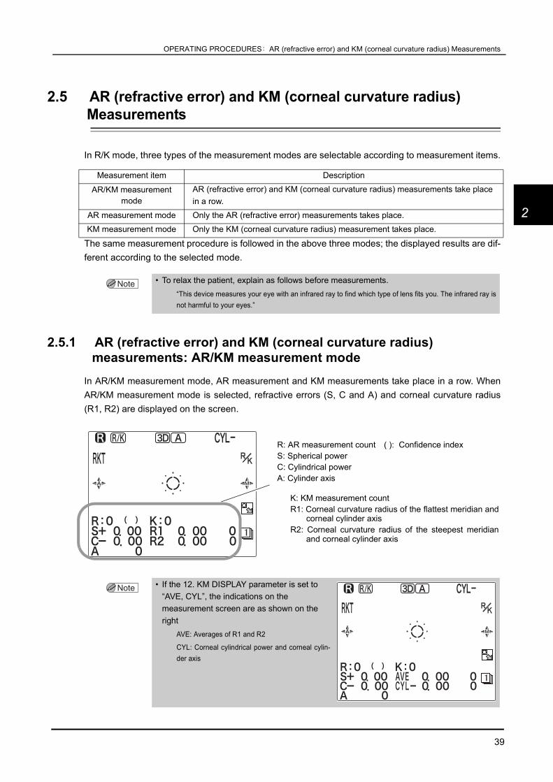
2.5.1 AR (refractive error) and KM (corneal curvature radius) measurements: AR/KM measurement mode
In AR/KM measurement mode, AR measurement and KM measurements take place in a row. WhenAR/KM measurement mode is selected, refractive errors (S, C and A) and corneal curvature radius(R1, R2) are displayed on the screen.
Measurement item Description
AR/KM measurement mode
AR (refractive error) and KM (corneal curvature radius) measurements take place in a row.
AR measurement mode Only the AR (refractive error) measurements takes place.
KM measurement mode Only the KM (corneal curvature radius) measurement takes place.
• To relax the patient, explain as follows before measurements.“This device measures your eye with an infrared ray to find which type of lens fits you. The infrared ray isnot harmful to your eyes.”
• If the 12. KM DISPLAY parameter is set to “AVE, CYL”, the indications on the measurement screen are as shown on the right
AVE: Averages of R1 and R2
CYL: Corneal cylindrical power and corneal cylin-der axis
R: AR measurement count ( ): Confidence indexS: Spherical powerC: Cylindrical powerA: Cylinder axis
K: KM measurement countR1: Corneal curvature radius of the flattest meridian and
corneal cylinder axis R2: Corneal curvature radius of the steepest meridian
and corneal cylinder axis

40
OPERATING PROCEDURES: AR (refractive error) and KM (corneal curvature radius) Measurements
1 Instruct the patient to look through the measuringwindow and watch the center of a picture of a balloonwithout straining as he or she sees it.
2 Manipulate the joystick to display thepatient’s eye on the screen.
By pulling the joystick backward, pushing itforward, tilting it to the left and right, the mainbody moves back, forth, to the right, and tothe left. By turning the upper part of the joy-stick, the main body moves up and down.
Align the device to the patient’s eye with right,left, up and down movements, and adjust thefocus with back and forth movements.
3 Perform alignment and focusing.The methods of alignment and focusing varyaccording to the 26. TRACKING SW parametersetting.
* See “ Auto-tracking mode and auto-shooting mode (page 36) for details.
Perform alignment by placing the mire ringreflected by the patient’s eye in the center of thetarget.
Perform focusing according to the indication ofthe on-screen focusing indicator.
• If the mire ring is not in the center of the pupil and the min. pupil mark is on the iris, turn off the auto-tracking function and bring the min. pupil mark into the center of the pupil to perform measurement, ignoring the mire ring.
• Auto-tracking or auto-shooting may not work on keratoconus or postoperative cornea.In such a case, turn off the auto-tracking and auto-shooting functions.
Scenery picture with a balloon
Mire ring Target
Focusing indicatorKM measuring light

41
OPERATING PROCEDURES: AR (refractive error) and KM (corneal curvature radius) Measurements
2
3D auto-tracking
1) Perform rough alignment and focusing bymanipulating the joystick to place in theworking range of auto-tracking.
2) When the device is placed within theworking range of auto-tracking, it automat-ically starts alignment and focusing.
Up-and-down auto-tracking
1) Perform rough alignment and focusing bymanipulating the joystick to place in theworking range of auto-tracking.
2) When the device is placed within theworking range of auto-tracking, it automat-ically starts alignment in the up-and-downdirection.
3) Manipulate the joystick to move the mirering reflected on the patient’s eye withinthe target.
4) As the focusing indicator is displayed,manipulate the joystick until the optimum focusing indicator is displayed.
Auto-tracking OFF
1) Manipulate the joystick to perform roughalignment and focusing.
2) Manipulate the joystick to move the mirering reflected on the patient’s eye withinthe target.
3) As the focusing indicator is displayed,manipulate the joystick until the optimumfocusing indicator is displayed.
During the focusing, maintain alignmentbetween the device and the patient’s eye.
• If eyelashes are on the min. pupil mark, correct AR measurement may not be possible. If the eyelid or eyelashes are on the mire ring, KM measurement may not be possible.
In such cases, instruct the patient to open his/her eye wider.
If the patient cannot open wider, lift the patient’s lid, paying attention not to press against the eyeball.
Up-and-down and side-to-side alignment: Auto
Focusing: Auto
Focusing: Manual
Up-and-down alignment: AutoSide-to-side alignment: Manual
Focusing: Manual
Up-and-down and side-to-side alignment: Manual

42
OPERATING PROCEDURES: AR (refractive error) and KM (corneal curvature radius) Measurements
When the main body is not within the working range of auto-tracking:
As the limit mark is displayed, manipulate the joystick or chinrest up/down button in the direction ofthe arrows.
<Examples of the limit mark>
Indication of the focusing indicator:
If the main body is not within the working range ofauto-tracking in the back-and-forth direction, thelimit mark is displayed
As the limit mark is displayed, manipulate the joy-stick in the direction of the mark.
Move the joystick back and forth until the focusingindicator shows the optimum condition.
Move the chinrest up.
Move the chinrest down.
Tilt the joystick slightly to the right.
Tilt the joystick slightly to the left.
Push the joystick forward.
Pull the joystick backward.
The level of the patient’s eye is too high from themeasuring unit.Move the chinrest down to lower the level of thepatient’s eye.
The patient’s eye is too far to the left from themeasuring unit.Tilt the joystick to the right to move the measur-ing unit to the right.
Limit mark
Too close to the patient’s eye
Optimum condition
Too far from the patient’s eye
Pull the joystick backward to move the main body awayfrom the patient’s eye.
Push the joystick forward to move the main body to-ward the patient’s eye.

43
OPERATING PROCEDURES: AR (refractive error) and KM (corneal curvature radius) Measurements
2
4 Measurement starts.Measurements take place automatically when the device is best aligned and focused on theeye (when the auto-shooting function is turned on).
* When the auto-shooting function is turned off, press the start button to start measurement.
KM measurement takes place.
A short beep is produced and KM-measured data and measurement count are dis-played.
KM measurement completes.
Pre-AR measurement takes place and the scenery chart is fogged.
AR measurement takes place.
A short beep is produced and the AR measured data and measurement count are dis-played.
The way of fogging in the second and subsequent measurements varies according to the 4. MEASMODE parameter setting.
AR measurement completes.
• The operator can start measurement by pressing the start button.Press the start button to start measurement when measurement has difficulty starting for patient’s whoblink often.
• Instruct the patient not to blink during measurement.
• When an error or error data appears, the cause may be one of those described below. If those signs appear again after repeating measurement, check the following:
a. Patient blinked during measurement.
b. The eyelid or eyelashes are on the min. pupil mark during AR measurement.
c. The eyelid or eyelashes are on the mire ring during KM measurement.
d. The patient’s pupil is smaller than the min. pupil mark.
Have the patient sit in a dark room for a while and wait until the pupil diameter becomes largeenough for measurement.
e. Retinal reflection is extremely low due to an optical disease such as a cataract.
f. There is some unusual reflection on the cornea during measurement.
g. There is an extreme distortion on cornea.
CON.Fogging is maintained on throughout the serial measurement.This mode is useful for children who do not fixate their eyes very long.
NOR.The patient’s view is fogged for each measurement even though the startbutton is held down.This mode is useful for patients who accommodate their eyes easily.

44
OPERATING PROCEDURES: AR (refractive error) and KM (corneal curvature radius) Measurements
<AR measurement error messages>
<KM measurement error messages>
• If the device gets out of alignment and focus during measurement, the measurement is interrupted. If the measurement is retried, the measured results are added to the former results and stored.
• To continue the measurement, press the start button again. “<<FINISH>>” disappears and auto-tracking starts for measurement. (except when the 31. PRINT parameter is set to AUTO).
• The device can store up to 10 measurements each for the right eye and left eye. If measurements exceed 10, the data is cleared in order from the oldest.
Error message Details
BLK(Blinking of the eye)
Measurement is impossible due to blinking and slightmovement of the eye.
Instruct the patient not to blink or not to move the eye untilmeasurement is completed.After the eye stopped blinking and moving, performmeasurement again.This error also may occur when reflected light from fundus islow.
ALM(Alignment error)
Focusing is not proper.Perform focusing and measurement again.
+OVR(Positive SPH range over error)
Spherical power is over the measurable limit of the + side.
-OVR(Negative SPH range over error)
Spherical power is over the measurable limit of the - side.
COVR(CYL range over error)
Cylindrical power is over the measurable limit.
CONF(Measured data reliability error)
Low-reliability data is obtained.Measure the subject again.* When the 44. ERROR DATA parameter is set to NO
S, C, A data displayed in yellow(Measured data reliability error)
Low-reliability data is obtained.Measure the subject again.* When the 44. ERROR DATA parameter is set to YES
Error message Details
BLK(Blinking of the eye)
Measurement is impossible because of blinking and slightmovement of the eye.
Instruct the patient not to blink or not to move the eye untilmeasurement is completed.After the eye stopped blinking and moving, perform measurementagain.
ALM(Alignment error)
Focusing is not proper.Perform focusing and measurement again.
FAR(Focus error: Too far from the patient’s eye)
Focusing is not proper.Perform focusing and measurement again.
NEAR(Focus error: Too close to the patient’s eye)
Focusing is not proper.Perform focusing and measurement again.

45
OPERATING PROCEDURES: AR (refractive error) and KM (corneal curvature radius) Measurements
2
5 Measurement completes.• When AI mode is YES:*1
When the specified number of KM measurements is performed, the measurement automaticallycompletes.*2
When the specified number of AR measurements is performed and the data is stable (no varia-tions), the measurement automatically completes.*3
Indications on the screen after the measurement:
“<<FINISH>>” is displayed on the screen.
When the specified number of KM measurementshave not been obtained, “<<KM?>>” is displayedon the screen.
When the start button is pressed, KM measure-ment stars again. As soon as the specified numberof KM measurements is obtained, “<<FINISH>>” isdisplayed on the screen.
• When AI mode is NO:
When the specified number of KM measurements*2 is performed, the measurement automaticallycompletes.
When the specified number of AR measurements*3 is performed, the measurement automaticallycompletes.
Release the start button to finish AR measurement.
Indications on the screen after measurement:
When the specified number of KM measurements have not been obtained, “<<KM?>>” is dis-played on the screen.
When the start button is pressed, the KM measurement stars again. As soon as the specifiednumber of KM measurements is obtained, “<<FINISH>>” is displayed on the screen.
* If three or more measurements are obtained, the median values are printed at the time of printing.
A thumbnail of the measurement ring image is displayed when measurement is completed.If necessary, check the full screen ring image.
See “ Measurement ring image display” (page 48) for details on the ring image display.
+OVRPositive corneal curvature radius range over
error)
The corneal curvature radius is too large and over themeasurable limit.
-OVR(Negative corneal curvature range over error)
The corneal curvature radius is too small and beyond themeasurable limit.
COVR(CYL range over error)
The cylindrical power is over the measurable limit.
*1. In this mode, AR measurement automatically completes as soon as stable data is obtained by the specified number of mea-surements.
*2. 3 through 10 times can be set by the 14. KM CONTINUE parameter. (Factory setting is 3 times.)*3. 3 through 10 times can be set by the 6. AR CONTINUE parameter. (Factory setting is 3 times.)

46
OPERATING PROCEDURES: AR (refractive error) and KM (corneal curvature radius) Measurements
6 Measure the other eye in the same manner.When the other eye is set in front of the measur-ing unit, the measuring unit returns to the originin the back-and-forth and side-to-side directions.
When measuring a single eye only, perform NTmeasurement.
For the method of switching to NT measurement,see “2.2.2 Switching between R/K measurement andNT measurement” (page 31).
7 In RKT mode, the measurement mode switches to NT measurement mode.For the method of switching to NT measurement, see “2.2.2 Switching between R/K measure-ment and NT measurement” (page 31).
For NT measurement, see “2.6 NT (Tonometry) Measurement: NT Mode” (page 61).
8 Let the patient know that the measurement is completed and instruct him or her to restcomfortably.
9 Print the measured results.Printing operation varies according to the 31. PRINT parameter setting.
See “2.7 Printing” (page 71) for details on printing.
• Instruct the patient to close his/her eye before starting the next measurement.Let the eye rest to avoid measurement failure by blinking.
31. PRINT parameter Printing method
AUTO Printing starts automatically at the completion of measurement.
MANUAL Press the print button to print the measured data out.
NO Printing does not occur.
• The printing contents can be changed by parameter settings.See “2.8 Parameter Settings” (page 76) for details.

47
OPERATING PROCEDURES: AR (refractive error) and KM (corneal curvature radius) Measurements
2
CATARACT measurement modeIf cataract or abnormal eyes cannot be measured during AR (refractive error) measurement, cataractmeasurement mode turns on automatically.In cataract measurement mode, measurement conditions are changed so as to enhance ease of mea-surements of even cataract or abnormal eyes.
When the device is placed in cataract measurement mode,“ ” is displayed on the screen and then measurementstarts.
The auto-tracking and auto-shooting functionswork in the same manner as ordinary measure-ment mode.
One of the following operations cancels cataract measurement mode:
• Switching the eye to be measured between the right eye and left eye.• Pressing the clear button .• Pressing the print button .
Printout sample in cataract measurement mode
According to the 45. CAT MARK parameter set-ting, “ ” indicating that measurement has beentaken in cataract measurement mode is printedas shown on the right.
* Factory setting: NO
• In cataract measurement mode, take note that measurement variations may occur more commonly compared to normal measurement mode.
Symbols of cataract measurement mode

48
OPERATING PROCEDURES: AR (refractive error) and KM (corneal curvature radius) Measurements
Measurement ring image displayThe TONOREF II projects measurement beams on the patient’s fundus and computation is performedby capturing the reflected beams as a ring image to measure the refractive errors of the patient’s eye.The TONOREF II displays this ring for the operator to observe the patient’s eye.
1 Perform normal measurement.A thumbnail of the ring image is displayed alongwith “<<FINISH>>” when measurement is com-plete.
2 Press the ring image enlargement button toswitch to the full screen display.
Observe the size, shape and such of the ringimage.
3 After checking the ring image, press the exit button to return to the measurementscreen.
• When both eyes have been measured, manipulating the joystick to switch the main body between the right and left also changes the display of the ring image between the right and left.

49
OPERATING PROCEDURES: AR (refractive error) and KM (corneal curvature radius) Measurements
2
2.5.2 AR (refractive error) Measurement: AR Measurement ModePerform AR measurement in the same manner as AR/KM measurement mode.KM (corneal curvature radius) measurement is not performed; KM-measured data is not displayed onthe screen.
1 Perform alignment and focusing and start AR measurement.See “2.5.1 AR (refractive error) and KM (corneal curvature radius) measurements: AR/KMmeasurement mode” (page 39) for the procedure before starting AR measurement.
Measurements take place automatically when the device is best aligned and focused on theeye (when the auto-shooting function is turned on).
* When the auto-shooting function is turned off, press the start button to start measurement.
Pre-AR measurement takes place and the scenery chart is fogged.
AR measurement takes place.
A short beep is produced and the AR measured data and measurement count are dis-played.
* The way of fogging in the second and subsequent measurements varies according to the 4. MEAS MODE parameter setting.
AR measurement completes.
CON.Fogging is maintained on throughout the serial measurement.This mode is useful for children who do not fixate their eyes very long.
NOR.The patient’s view is fogged for each measurement even though the startbutton is held down.This mode is useful for patients who accommodate their eyes easily.
• If the device gets out of alignment and focus during measurement, the measurement is interrupted. If the measurement is retried, the measured results are added to the former results and stored.
• To continue the measurement, press the start button again. “<<FINISH>>” disappears and auto-tracking starts for measurement (except when the 31. PRINT parameter is set to AUTO).
• The device can store up to 10 measurements each for the right eye and left eye. If measurements exceed 10, the data is cleared in order from the oldest.
R: AR measurement count ( ): Confidence indexS: Spherical powerC: Cylindrical powerA: Cylinder axis angle
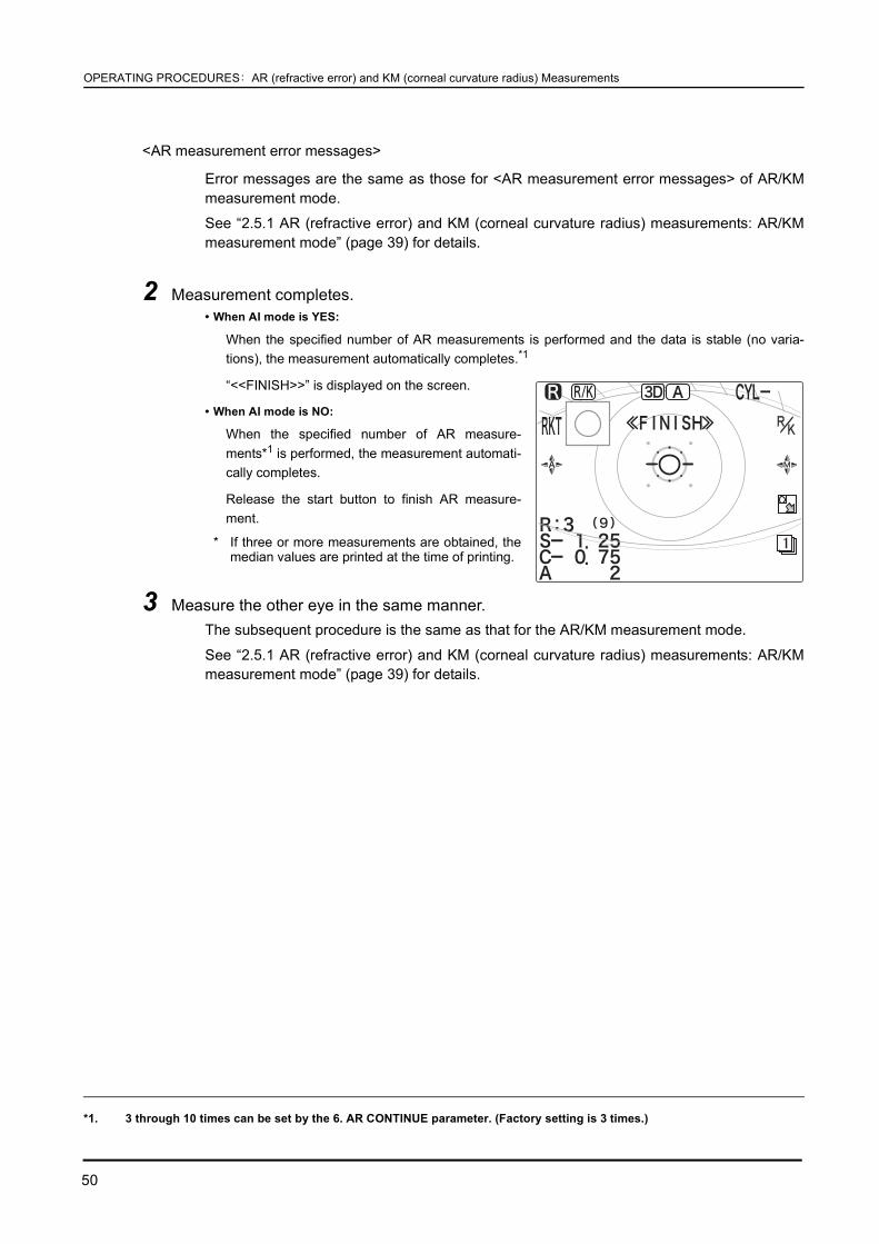
50
OPERATING PROCEDURES: AR (refractive error) and KM (corneal curvature radius) Measurements
<AR measurement error messages>
Error messages are the same as those for <AR measurement error messages> of AR/KMmeasurement mode.
See “2.5.1 AR (refractive error) and KM (corneal curvature radius) measurements: AR/KMmeasurement mode” (page 39) for details.
2 Measurement completes.• When AI mode is YES:
When the specified number of AR measurements is performed and the data is stable (no varia-tions), the measurement automatically completes.*1
“<<FINISH>>” is displayed on the screen.
• When AI mode is NO:
When the specified number of AR measure-ments*1 is performed, the measurement automati-cally completes.
Release the start button to finish AR measure-ment.
* If three or more measurements are obtained, themedian values are printed at the time of printing.
3 Measure the other eye in the same manner.The subsequent procedure is the same as that for the AR/KM measurement mode.
See “2.5.1 AR (refractive error) and KM (corneal curvature radius) measurements: AR/KMmeasurement mode” (page 39) for details.
*1. 3 through 10 times can be set by the 6. AR CONTINUE parameter. (Factory setting is 3 times.)
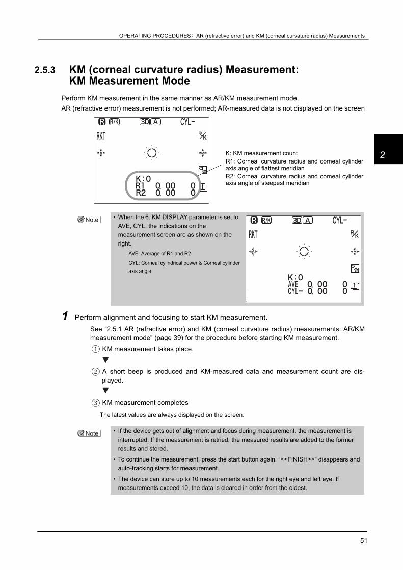
51
OPERATING PROCEDURES: AR (refractive error) and KM (corneal curvature radius) Measurements
2
2.5.3 KM (corneal curvature radius) Measurement: KM Measurement Mode
Perform KM measurement in the same manner as AR/KM measurement mode.AR (refractive error) measurement is not performed; AR-measured data is not displayed on the screen
1 Perform alignment and focusing to start KM measurement.See “2.5.1 AR (refractive error) and KM (corneal curvature radius) measurements: AR/KMmeasurement mode” (page 39) for the procedure before starting KM measurement.
KM measurement takes place.
A short beep is produced and KM-measured data and measurement count are dis-played.
KM measurement completes
The latest values are always displayed on the screen.
• When the 6. KM DISPLAY parameter is set to AVE, CYL, the indications on the measurement screen are as shown on the right.
AVE: Average of R1 and R2
CYL: Corneal cylindrical power & Corneal cylinderaxis angle
• If the device gets out of alignment and focus during measurement, the measurement is interrupted. If the measurement is retried, the measured results are added to the former results and stored.
• To continue the measurement, press the start button again. “<<FINISH>>” disappears and auto-tracking starts for measurement.
• The device can store up to 10 measurements each for the right eye and left eye. If measurements exceed 10, the data is cleared in order from the oldest.
K: KM measurement countR1: Corneal curvature radius and corneal cylinderaxis angle of flattest meridianR2: Corneal curvature radius and corneal cylinderaxis angle of steepest meridian

52
OPERATING PROCEDURES: AR (refractive error) and KM (corneal curvature radius) Measurements
<KM measurement error messages>
Error messages are the same as those for <KM measurement error messages> of AR/KMmeasurement mode.
See “2.5.1 AR (refractive error) and KM (corneal curvature radius) measurements: AR/KM mea-surement mode” (page 39) for details.
2 Measurement completes.When the specified number of KM measurements is performed, the measurement automaticallycompletes.*1
Indications on the screen after measurement:
“<<FINISH>>” is displayed on the screen.
When the specified number of KM measurementshave not been obtained, “<<KM?>>” is displayedon the screen.
When the start button is pressed, the KM mea-surement stars again. As soon as the set times ofKM measurements are obtained, “<<FINISH>>” isdisplayed on the screen.
3 Measure the other eye in the same manner.The subsequent procedure is the same as that for AR/KM measurement mode.
See “2.5.1 AR (refractive error) and KM (corneal curvature radius) measurements: AR/KMmeasurement mode” (page 39) for details.
*1. 3 through 10 times can be set by the 14. KM CONTINUE parameter. (Factory setting is 3 times.)

53
OPERATING PROCEDURES: AR (refractive error) and KM (corneal curvature radius) Measurements
2
2.5.4 CS (Corneal Size) Measurement
1 Press the CS/PS/PD button to enter CSmeasurement mode.
“<<CORNEAL SIZE>>”, guide lines and “STARTSW: CAPTURE” are displayed on the screen.
Pressing the CS/PS/PD button switches themode in the following order:
CS→ PS→ PD→ CS→ ...
2 Manipulate the joystick to perform alignment andfocusing of the patient’s eye.
The auto-tracking and auto-focusing functionsare automatically turned off.
Manually operate the joystick to perform align-ment and focusing according to the patient’s eye.
3 Press the start button to capture the image.The screen switches from a moving image to a still image.
After capturing, instruct the patient to rest comfortably.
4 Press the right button or left button toalign the guide line on the right of the patient’scornea.
The guide line to be aligned is displayed in pink.
5 Press the down button to change theselected guide line.
The left guide line is displayed in pink.
Each time the switch is pressed, the guide line isdisplayed in pink right and left, alternately.
• If the mode is switched to CS measurement mode from when a still image is displayed on the PS (Pupil SIze) measurement screen, a still image is displayed.
• If the start button is pressed before the right button or left button has been pressed, the still image returns to the moving image that allows for recapturing.
Guide lines
Align the guide line with the right end of thepatient’s cornea.
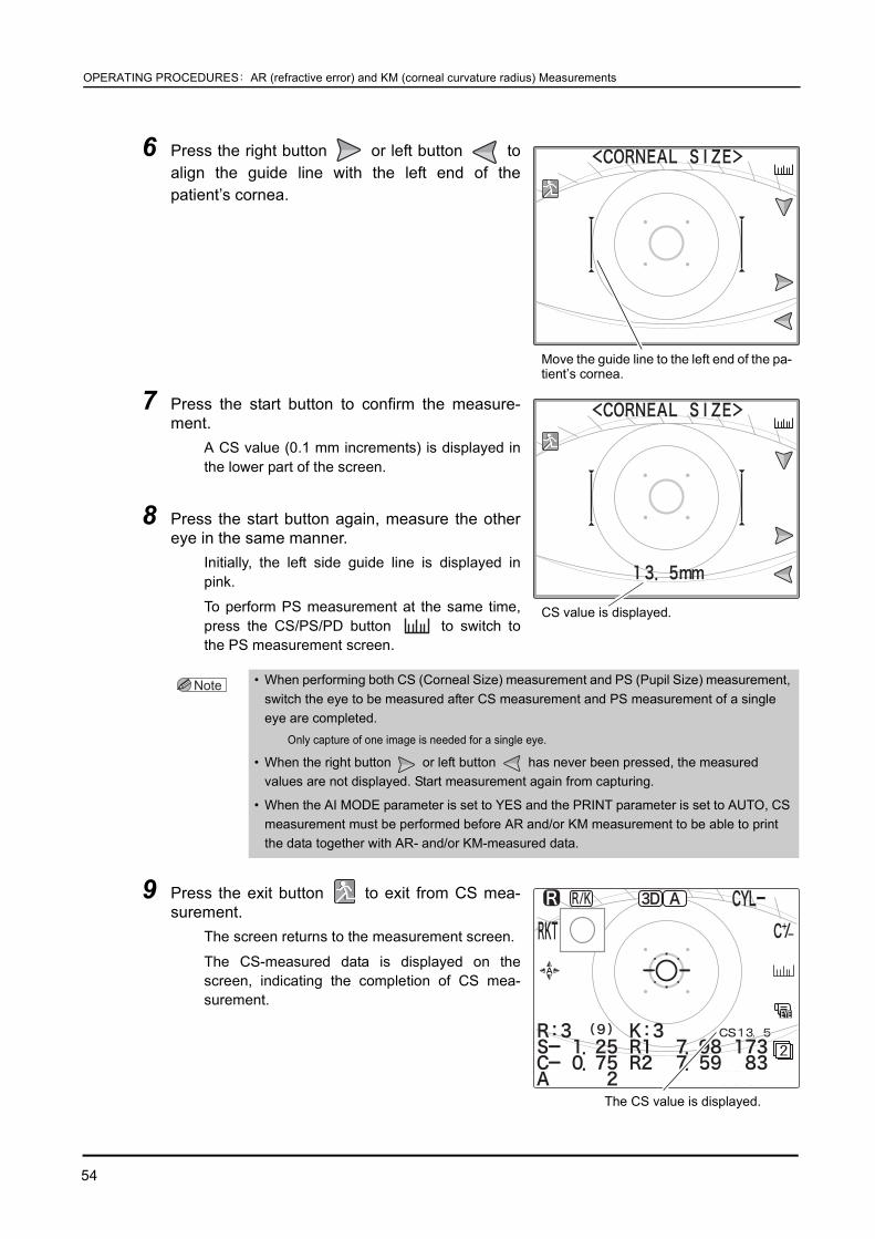
54
OPERATING PROCEDURES: AR (refractive error) and KM (corneal curvature radius) Measurements
6 Press the right button or left button toalign the guide line with the left end of thepatient’s cornea.
7 Press the start button to confirm the measure-ment.
A CS value (0.1 mm increments) is displayed inthe lower part of the screen.
8 Press the start button again, measure the othereye in the same manner.
Initially, the left side guide line is displayed inpink.
To perform PS measurement at the same time,press the CS/PS/PD button to switch tothe PS measurement screen.
9 Press the exit button to exit from CS mea-surement.
The screen returns to the measurement screen.
The CS-measured data is displayed on thescreen, indicating the completion of CS mea-surement.
• When performing both CS (Corneal Size) measurement and PS (Pupil Size) measurement, switch the eye to be measured after CS measurement and PS measurement of a single eye are completed.
Only capture of one image is needed for a single eye.
• When the right button or left button has never been pressed, the measured values are not displayed. Start measurement again from capturing.
• When the AI MODE parameter is set to YES and the PRINT parameter is set to AUTO, CS measurement must be performed before AR and/or KM measurement to be able to print the data together with AR- and/or KM-measured data.
Move the guide line to the left end of the pa-tient’s cornea.
CS value is displayed.
The CS value is displayed.
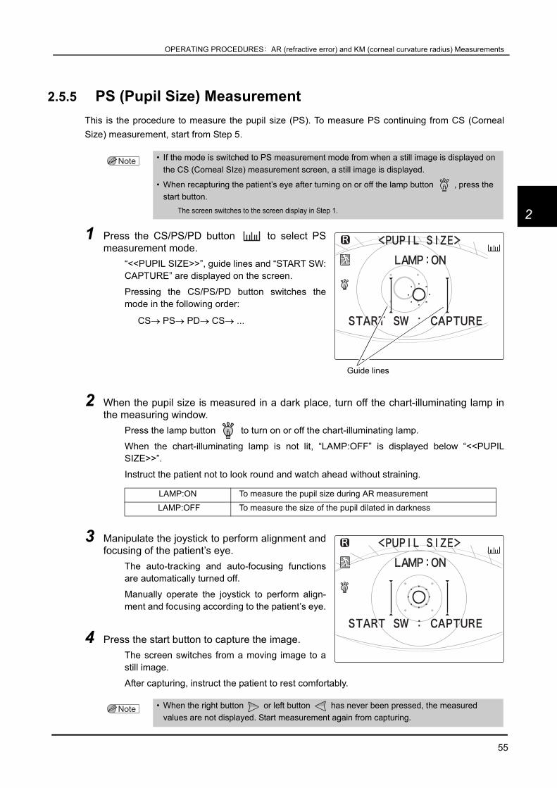
55
OPERATING PROCEDURES: AR (refractive error) and KM (corneal curvature radius) Measurements
2
2.5.5 PS (Pupil Size) MeasurementThis is the procedure to measure the pupil size (PS). To measure PS continuing from CS (CornealSize) measurement, start from Step 5.
1 Press the CS/PS/PD button to select PSmeasurement mode.
“<<PUPIL SIZE>>”, guide lines and “START SW:CAPTURE” are displayed on the screen.
Pressing the CS/PS/PD button switches themode in the following order:
CS→ PS→ PD→ CS→ ...
2 When the pupil size is measured in a dark place, turn off the chart-illuminating lamp inthe measuring window.
Press the lamp button to turn on or off the chart-illuminating lamp.
When the chart-illuminating lamp is not lit, “LAMP:OFF” is displayed below “<<PUPILSIZE>>”.
Instruct the patient not to look round and watch ahead without straining.
3 Manipulate the joystick to perform alignment andfocusing of the patient’s eye.
The auto-tracking and auto-focusing functionsare automatically turned off.
Manually operate the joystick to perform align-ment and focusing according to the patient’s eye.
4 Press the start button to capture the image.The screen switches from a moving image to astill image.
After capturing, instruct the patient to rest comfortably.
• If the mode is switched to PS measurement mode from when a still image is displayed on the CS (Corneal SIze) measurement screen, a still image is displayed.
• When recapturing the patient’s eye after turning on or off the lamp button , press the start button.
The screen switches to the screen display in Step 1.
LAMP:ON To measure the pupil size during AR measurement
LAMP:OFF To measure the size of the pupil dilated in darkness
• When the right button or left button has never been pressed, the measured values are not displayed. Start measurement again from capturing.
Guide lines

56
OPERATING PROCEDURES: AR (refractive error) and KM (corneal curvature radius) Measurements
5 Press the right button or left button toalign the guide line on the right of the patient’spupil.
The guide line to be aligned is displayed in pink
6 Press the down button to change theselected guide line.
The left guide line is displayed in pink.
Each time the switch is pressed, the guide line isdisplayed in pink right and left, alternately.
7 Press the right button or left button toalign the guide line with the left end of thepatient’s pupil
8 Press the start button to confirm the measure-ment.
A PS value (0.1 mm increments) is displayed inthe lower part of the screen.
9 Press the start button again, measure the other eye in the same manner.
10 Press the exit button to exit from PS measure-ment.
he screen returns to the measurement screen.
The PS-measured data is displayed on thescreen, indicating the completion of PS mea-surement.
• When the right button or left button has never been pressed, the measured values are not displayed. Start measurement again from capturing.
• When the AI MODE parameter is set to YES and the PRINT parameter is set to AUTO, PS measurement must be performed before AR and/or KM measurement to be able to print the data together with AR- and/or KM-measured data.
Align the guide line on the right of the pa-tient's pupil.
Align the guide line with the left end of thepatient's pupil.
The PS value is displayed.

57
OPERATING PROCEDURES: AR (refractive error) and KM (corneal curvature radius) Measurements
2
2.5.6 PD (Pupillary Distance) Measurement
Auto-PD measurement
When the 63. AUTO PD parameter is set to YES, at themoment where measurement of both eyes is completed,PD measurement is also completed and then the PD valueis displayed.Also, the near PD is automatically calculated.
Manual PD MeasurementWhen the 63. AUTO PD parameter is set to NO, perform measurement by the following procedure.Even when the parameter is set to YES, manual PD measurement can be performed.
1 Press the CS/PS/PD button to select PDmeasurement mode
On the screen, “<PD>”, “R”, “C”, and “L” are dis-played.
2 Instruct the patient not to move his/her head and eyes during measurement.
• A PD value is printed out with measured data.
• A monocular PD is not measured.Measure the monocular PD manually.
• The calculated near PD is not displayed on the screen but is printed out with the AR-measured data (when the 55. NEAR PD PRINT parameter is set to YES).
• “PD ERR” displayed on the screen may disable PD measurement. Check the PD window.If the PD window is blocked, remove the obstacles. If dust settles on the PD window, dampen a cloth withrubbing alcohol and gently wipe the dust off.
If “PD ERR” is still displayed on the screen even after making the corrections described above, install thedevice in a low light interference environment since the error may occur due to light interference.
The PD value is displayed.

58
OPERATING PROCEDURES: AR (refractive error) and KM (corneal curvature radius) Measurements
3 After proper alignment of the right eye and lefteye, press the Start button each time.
Auto-tracking and auto focusing function areturned off automatically, however when in the PDmeasurement mode, the focusing indicator isdisplayed.
To measure monocular PD at the same time asthe binocular PD, press the Start button everyafter proper alignment of the right-eye, center,and the left-eye.
4 When the measurement is completed, the mea-sured PD is displayed on the screen.
The measurement is completed when the R(right) and L (left) signs disappear.
To measure the monocular PD, press the startbutton in the center.
5 Press the exit button to exit from PD mea-surement
The screen returns to the measurement screen.
The measured PD is displayed on the screen,indicating that the completion of measurement.
• If the patient’s head is tilted, straighten it before starting measurement.
• To locate in the exact center position, have the patient wear the frames with a mark in its center and bring the mark in focus.
It is recommendable to use a pupillary distance meter such as the NIDEK PM-600 in order to obtain pre-cise monocular PD.
• “R” (right), “C” (center) and “L” (left) on the LCD display disappear in order by pressing the start button to indicate that detection of each position has been completed.
The mark of the detected position disappears.
The PD value is displayed.

59
OPERATING PROCEDURES: AR (refractive error) and KM (corneal curvature radius) Measurements
2
2.5.7 Measuring Hard Contact LensesTo measure hard contact lenses, use the provided CL holder. The contact lens holder is incorporatedin the spherical model eye.The CL holder is integral with the spherical model eye.
1 Fill the concave top of the CL holder withwater
Use a commercial pipette to fill the concavetop of the CL holder completely with water.
2 Place a contact lens with the surface to bemeasured facing upward over the contact lensholder.
When measuring the concave surface, placethe lens with the concave surface up asshown in the figure on the right. Conversely,when measuring the convex surface, placethe lens with the convex surface up.
3 Pull out the two fixing pins and remove thestack of chinrest paper from the chinrest.
• Be careful not to let bubbles get under the lens or water or dust on the lens.
Pipette
Contact lens
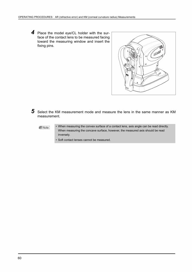
60
OPERATING PROCEDURES: AR (refractive error) and KM (corneal curvature radius) Measurements
4 Place the model eye/CL holder with the sur-face of the contact lens to be measured facingtoward the measuring window and insert thefixing pins.
5 Select the KM measurement mode and measure the lens in the same manner as KMmeasurement.
• When measuring the convex surface of a contact lens, axis angle can be read directly. When measuring the concave surface, however, the measured axis should be read inversely.
• Soft contact lenses cannot be measured.

61
OPERATING PROCEDURES: NT (Tonometry) Measurement: NT Mode
2
2.6 NT (Tonometry) Measurement: NT Mode
During NT measurement, the types of the target and focusing indicator are parameter (74. TARGETTYPE) -selectable from two options:
The following description is illustrated with the screens displayed on condition that the 33.TARGET TYPE parameter is set to RKT.
1 Press the RNG button to select the mea-surement range.
Every time the button is pressed, the measure-ment range switches in the following order: “APC40” → “APC 60” → “40” → “60” → “APC 40” →….
Just after power-up, “APC 40” is set by default.
2 If necessary, disable the eyelid detectionmode
Disable the mode by pressing the eyelid detec-tion mode button .
For the details of the eyelid detection mode, see“2.6.1 Eyelid detection mode” (page 70).
RKTDuring the R/K and NT measurements, the same target and focusing indicator are displayed (Factory setting).
AR/NTDuring the NT measurement, a special alignment target and focusing indicator are displayed.
Measurement range
Guide for selection Air pressure controls
APC 40 NormalThe peak of the air pressure is automatically controlled within the range of 1 to 40 mmHg.
APC 6040 mmHg or more of intraocular pressure
The peak of the air pressure is automatically controlled within the range of 1 to 60 mmHg.
40The intraocular pressure fluctuates substantially.
The peak of the air pressure is fixed within the range of 1 to 40 mmHg.
6040 mmHg or more of intraocular pressure that fluctuates substantially.
The peak of the air pressure is fixed within the range of 1 to 60 mmHg.
Measurement range
Eyelid detection mode marker

62
OPERATING PROCEDURES: NT (Tonometry) Measurement: NT Mode
3 Set the safety space between the patient’s eye and air nozzle with the safety stop-per.
1) Pressing the safety stopper*1, operate thejoystick so that the air nozzle approachesthe cornea slowly.
While pressing the safety stopper, “RTN TOORG” blinks on the screen.
2) While watching from a side of the device,release the safety stopper when the spacebetween the patient’s eye and the air noz-zle becomes 8 to 10 mm.
The blinking “RTN TO ORG” on the screen dis-appears when the safety stopper locks themain body to the determined position.
3) Slightly push the joystick backward and pull it backward to confirm that the main bodydoes not move toward the patient from the position locked in Step 2.
4 Provide the patient with an explanation about the measurement.To help the patient relax, provide the patient with such an explanation before starting themeasurement as:
“You may be surprised by air puffed into your eye, but do not worry. Please be patient andrelax for a moment until I can measure your intraocular pressure three times per eye.”
WARNING • Before the measurement, be sure to set the safety stopper.The air nozzle may touch and scratch the cornea.
*1. While the safety stopper is pushed down in NT measurement mode, the “RTN TO ORG” message is displayed on thescreen and the auto-tracking and auto-shooting functions are disabled.
Safety stopper
Press
8 to 10 mm
cornea Air nozzle

63
OPERATING PROCEDURES: NT (Tonometry) Measurement: NT Mode
2
5 Manipulate the joystick to display the patient’s eye on the screen.By tilting the joystick to the right and left, themain body moves right, left, back and forth.By turning the upper part of the joystick, themeasuring unit moves up and down.
Align the eye position to the measuring pointwith right, left, up and down movements.Adjust the focus with back and forth move-ments.
6 Instruct the patient to look at the fixation light(green luminous spot) in the air nozzle.
7 Perform alignment and focusing.The methods of alignment and focusing varyaccording to the 26. TRACKING SW parametersetting.
* See “ Auto-tracking mode and auto-shootingmode” (page 36) for details.
Align the alignment spot reflected over thepatient’s eye with the target ( ).
Perform focusing according to the indication ofthe focusing indicator displayed on the screen.
• Ensure that the patient's eyelashes or eyelid are not in the applanation area and the patient's eye is not watery.
These factors cause measurement errors or decrease the accuracy of measurements.
If the patient's eyelashes or eyelid are within the applanation area, lift the patient's lid, paying attention notto press against the eyeball.
If the eye is watery, have the patient blink his or her eyes or wipe tears.
• Select whether to illuminate or blink the fixation light by setting the 24. FIX LED BLINK parameter.
Applanation area
Alignment spot Target
Focusing indicator

64
OPERATING PROCEDURES: NT (Tonometry) Measurement: NT Mode
In the case of 3D auto-tracking:
1) Perform rough alignment and focusing bymanipulating the joystick to move thealignment spot in the working range ofauto-tracking
2) When the alignment spot is placed withinthe working range of auto-tracking, thedevice automatically starts alignment andfocusing.
In the case of 2D auto-tracking:
1) Perform rough alignment and focusing bymanipulating the joystick to move thealignment spot in the working range ofauto-tracking.
2) When the alignment spot is placed withinthe working range of auto-tracking, thedevice automatically starts alignment.
3) As the focusing indicator is displayed,manipulate the joystick until the optimalfocusing indicator is displayed.
When the auto-tracking function is turned off:
1) Manipulate the joystick to move the align-ment spot reflected by the patient’s eyewithin the alignment target.
2) As the focusing indicator is displayed,manipulate the joystick until the optimalfocusing indicator is displayed.
During the focusing, maintain alignmentbetween the device and the patient’s eye.
• When the 74. TARGET TYPE parameter is set to AR/NT, the indications on the screen are as shown on the right.
The indication of the applanation area andfocusing indicator is different from the one dis-played when the parameter is set to RKT.
Applanation area
Up-and-down and side-to-side alignment: Auto
Focusing: Auto
Focusing: Manual
Up-and-down and side-to-side alignment: Auto
Focusing: Manual
Up-and-down and side-to-side alignment: Manual

65
OPERATING PROCEDURES: NT (Tonometry) Measurement: NT Mode
2
If the main body gets out of the working range of auto-racking in the back-and-forth direction:
As the limit mark is displayed, manipulate the joystick in the direction of the arrow.
<Examples of displayed limit marks>
Indication of the focusing indicator:
If the main body gets out of the working range of auto-tracking in the back-and-forth direc-tion, the limit mark is displayed.
Manipulate the joystick in accordance with theindication of the focusing indicator.
Push the joystick backward and pull it backwarduntil the focusing indicator shows the optimal state.
• The device may not perform correct measurement when the eyelashes or eyelid is in the applanation area.
In such cases, instruct the patient to open his or her eye wider.
If the patient cannot open wider, lift the patient's lid, paying attention not to press against the eyeball.
Move the chinrest up.
Move the chinrest down.
Tilt the joystick slightly to the right.
Tilt the joystick slightly to the left.
Push the joystick forward.
Pull the joystick backward.
The patient eye is too high from the measuringunit. Move down the chinrest to lower the level ofthe eye.
The patient’s eye is too far to the left from tmeasuring unit. Tilt the joystick to the right move the measuring unit to the right.
Limit mark

66
OPERATING PROCEDURES: NT (Tonometry) Measurement: NT Mode
8 Start the measurement.• When the auto-shooting function is on:
The measurement takes place automatically when the device is best aligned and focuses on theeye.
• When the auto-shooting function is off:
Press the start button to start the measurement.
• The operator can start the measurement by pressing the start button.Press the start button to start the measurement when it takes some time until the measurement takesplace for patients who often blink.
• To obtain accurate measured data, measure wide-open, fixated eyes on condition that the patient is placed in a stable position.
• Air may be puffed while the eye is blinking. In this case, accurate measurement data cannot be obtained and the patient will feel uncomfortable.
Pull the joystick backward and wait until the eye stops blinking.
• If the alignment spot appears blurry on the cornea because of corneal wound, etc., the device may not start the measurement even when the proper alignment and focus are obtained.
Press the start button to start the measurement.
Too close to the patient’s eye
Optimal state
Too far from the patient’s eye
Pull the joystick backward to move the main body awayfrom the patient’s eye.
Push the joystick forward to move the main body to-ward the patient’s eye.
AR/NT type RKT type

67
OPERATING PROCEDURES: NT (Tonometry) Measurement: NT Mode
2
<Error messages during NT measurement>
• If the measurement was not performed correctly for some reasons, an abbreviated error message is displayed above the measurement range indication.
In this case, eliminate the cause of the error, following the suggestions in the table below andperform the measurement again.
Error message DescriptionALM
(Alignment error)Alignment is not proper.
Perform the alignment and the measurement again.
APL(Applanation error)
As the eye was not opened enough, corneal applanation was insufficient.
Instruct the patient to open his or her eyes wider.If the patient cannot do so, ask an assistant to open the eyelids wider by using a swab, etc.
OVR(Over the measurement range)
The intraocular pressure exceeds the preset measurement range.Switch the measurement range to “APC 60” or “60” and perform the measurement again.
BLK(Blinking of the eye)
The measurement is impossible because of blinking and slight movement of the eye.
Instruct the patient not to blink or move the eye until the measurement is completed.After the eye stopped blinking and moving, perform the measurement again.
PCE(APC error)
The patient’s eye cannot be measured with the air pressure which is controlled by the APC function because of substantial fluctuation in intraocular pressure.
Switch the measurement range from “APC 40” to “40” or from “APC 60” to “60”.
TOO CLOSE The space between the patient’s eye and the air nozzle is 9 mm or less.Pull the joystick backward to increase the space between them.
NO SEARCH The alignment spot cannot be detected.
CHECK THE EYE
This error appears when five consecutive APL errors with measurement values occur.
Check the condition of the patient’s eye.When APL errors continuously occur with no measurement values, this error is not displayed.
OPEN THE EYE WIDERAlignment is proper, but the eyelid detection lights cannot be detected.
Instruct the patient to open his/her eyes wider.This error occurs only when the eyelid detection mode is turned on.
Error message and measured data

68
OPERATING PROCEDURES: NT (Tonometry) Measurement: NT Mode
If the “CHECK THE EYE” error occurs:Check the condition of the patient’s eye.
If the patient cannot open the eye wide or eyelashes are over the applanation area, youhave to help the patient open the eye wide.
For a watery eye, have the patient blink his or her eyes, or wipe the tears.
The error is cleared when normal measured data is obtained.
The APL error may occur in a row even though the eye seems to be in normal conditions.
In this case, reset the 21. SET LOW CONF parameter to YES and perform the measurementagain.
The measurement value is displayed with a * mark, indicating low confidence data.
For the setting method, see “2.8 Parameter Settings” (page 76).
The measurement may be performed and measured data may be displayed even though ameasurement error (APL or ALM) occurred. Such data with the * is referred to as “low confi-dence data”.
The low confidence data is cleared together with the error message; it is also possible tomaintain the measured data with the * mark on the screen by setting the correspondingparameter.
9 Measured data is displayed on the screenMeasured data and average data are displayedon the screen.
After air is puffed, and the charge indicator is dis-played for several seconds to indicate that thedevice is in standby mode.
10 Repeat Steps 8 to 9 to perform the measurement three times or more.*1
*1. The intraocular pressure fluctuates with the patient’s pulse and breath. As the non-contact tonometer measures the in-stantaneous intraocular pressure, the average of the three or more measured values should be generally regarded as theintraocular pressure.
Eyelid is over the applanation area. Eyelashes are over the applanation area.
Charge indicator

69
OPERATING PROCEDURES: NT (Tonometry) Measurement: NT Mode
2
11 Pull the joystick backward once and move themain body to the other eye.
The measured eye indicator of the other eyeblinks and the measuring unit returns to the ori-gin in the back-and-forth and side-to-side direc-tions.
12 Measure the intraocular pressure of the other eyein the same way as Steps 5 to 10.
13 Inform the patient of the completion of the measurement and instruct him or her to take acomfortable position.
14 Print the measured results.• When the 31. PRINT parameter is set to AUTO:
Printout is automatically started after the number of measurements set by the 25. NT CONTINUEparameter.
• When the 31. PRINT parameter is set to MANUAL ALL:
Press the print button to produce a printout.
For the details of the printout, see “3.2 Connecting to the NIDEK Auto Lensmeter (LM)”(page 95).
• The contents of printout are parameter-changeable.For details, see “2.8 Parameter Settings” (page 76).

70
OPERATING PROCEDURES: NT (Tonometry) Measurement: NT Mode
2.6.1 Eyelid detection modeWith this mode, the device always checks the eye for the amount of eye-opening and the measure-ment takes place automatically only when the eyelid is opened wide.
Activating and cancelling eyelid detection mode
Press the eyelid detection mode button to activate orcancel the mode.When eyelid detection mode is canceled, the eyelid detec-tion cancel marker “ ” is displayed in the lower rightof the screen.
About eyelid detection mode
When eyelid detection mode is activated, eye-opening ischecked by the eyelid detection lights as shown on theright. (When the eyelid is over the applanation area, thedetection lights disappear.The measurement takes place automatically when theeyelid is opened wide on condition that alignment andfocusing are obtained.If eye-opening is insufficient, the “OPEN THE EYEWIDER” message is displayed to warn the operator; underthe condition, the measurement does not take place auto-matically.
• It is recommended to cancel eyelid detection mode only when it is difficult to perform the measurement with the eyelid detection mode activated.
The cancellation of the mode may result in increase in the occurrence of measurement errors andincrease in fluctuations in measured data.
Eyelid detection cancel marker
Eyelid detection lights
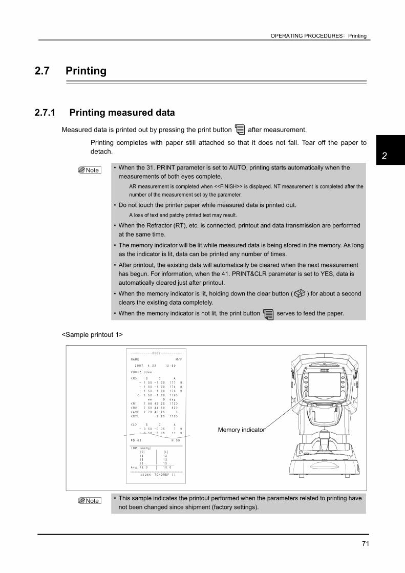
71
OPERATING PROCEDURES: Printing
2
2.7 Printing
2.7.1 Printing measured dataMeasured data is printed out by pressing the print button after measurement.
Printing completes with paper still attached so that it does not fall. Tear off the paper todetach.
<Sample printout 1>
• When the 31. PRINT parameter is set to AUTO, printing starts automatically when the measurements of both eyes complete.
AR measurement is completed when <<FINISH>> is displayed. NT measurement is completed after thenumber of the measurement set by the parameter.
• Do not touch the printer paper while measured data is printed out.A loss of text and patchy printed text may result.
• When the Refractor (RT), etc. is connected, printout and data transmission are performed at the same time.
• The memory indicator will be lit while measured data is being stored in the memory. As long as the indicator is lit, data can be printed any number of times.
• After printout, the existing data will automatically be cleared when the next measurement has begun. For information, when the 41. PRINT&CLR parameter is set to YES, data is automatically cleared just after printout.
• When the memory indicator is lit, holding down the clear button ( ) for about a second clears the existing data completely.
• When the memory indicator is not lit, the print button serves to feed the paper.
• This sample indicates the printout performed when the parameters related to printing have not been changed since shipment (factory settings).
Memory indicator

72
OPERATING PROCEDURES: Printing
<Sample printout 2>
• Items marked with “ ” indicate whether or not to print according to parameter settings.See PRINT1 to PRINT3 of “2.8.1 Parameter tables” (page 79).
Patient No.Space for name and sexDate and time of measurementVertex distance*1Near working distance*2
AR measurement, Confidence index*3S = Spherical powersC = Cylindrical powersA = Cylinder axis
AR median values*4
SE value*5
Eyeprint*6
Trial lens data*7CL conversion values*8
KM measurementR1 = Flattest meridianR2 = Steepest meridianAVE = Average of R1 and R2CYL = Corneal cylindrical powerdeg = Corneal cylinder axis
KM median values*9
CS measurement, PS measurement(ON or OFF of the lamp during PS measurement)
Measurable range over error
Pupillary distanceDistance PD, (Monocular PD), Near PD*10
Intraocular pressures
Average intraocular pressure
Comments*12

73
OPERATING PROCEDURES: Printing
2
* 1 Vertex distance
The distance between the corneal vertex to the posterior surface of spectacle lenses.* 2 Near working distance
Used for near PD calculation. Changeable in the 35 to 70 cm or in the 14- to 28-inch range by thecorresponding parameter.
* 3 Confidence index
One of six confidence indexes (9, 8, 7, 6, 5 or E) is printed out. E is erroneous data.
The higher the confidence index, the higher the reliability of measured data.
Measured data obtained in cataract measurement mode is marked with the preceding “ ” symbol.* 4 AR median value
Printed out when three or more AR measurements are in the memory.* 5 SE (Spherical Equivalent) value
Calculated for the AR median values (or the latest values when AR median values have not beenobtained) and CL conversion values.
* 6 Eyeprint
Tells graphically the patient’s refractive status based on the AR median values (or the latest valueswhen AR median values have not been obtained). There are 8 eyeprint patterns.
* 7 Trial lens data
Based on the AR median values (or the latest values when AR median values have not beenobtained), the cylinder reading direction is automatically converted so that a spherical trial lens haslower power as reference data.
* 8 Contact lens conversion value
The AR median values (or the latest values when AR median values have not been obtained) areconverted into CL values, letting the vertex distance (VD) be 0 mm.
* 9 KM median values
Printed out when three or more KM measurements are in the memory.
• Emmetropia • Astigmatism • Simple myopic astigmatism
• Myopia • Myopic astigmatism • Simple hyperopic astigmatism
• Hyperopia • Hyperopic astigmatism

74
OPERATING PROCEDURES: Printing
* 10 PD for near vision
PD for a near working distance of 40 cm (factory setting). Use it for prescriptions of reading glassesor bifocals.
* 11 Comments
It is possible to enter the desired letters or symbols.
See “2.8.3 Entering comments” (page 91) for the entering method.
2.7.2 EyeprintAside from normal printing, the eyeprint button serves to print the eyeprint and PD value only based onthe AR median values or latest values.The eyeprint is printed out regardless of the 52. EYEPRINT parameter. It helps you explain the patient therefractive condition of his or her eyes.There are 8 eyeprint patterns, the same as those onthe normal printing described in “2.7.1 Printing measured
data” (page 71).
• It is possible to print the eyeprint when measured data is stored and the memory indicator is lit.
• With monocular measurement only, printing can be performed.

75
OPERATING PROCEDURES: Printing
2
2.7.3 Printing parameter settingsThe present parameter settings, set time, comments and maintenance program versions are printed out.
1 Press the parameter button for about a second.The PARAMETER SETTING screen is displayed. The parameter No. and parameter namesare displayed.
See “2.8 Parameter Settings” (page 76) for details on the parameters.
2 Press the print button .The parameter settings areprinted as in the right.
The parameter settings areprinted regardless of the dis-played page on the PARAME-TER SETTING screen, all theparameter settings are printedout.
Parameters
Clock setting
Comments
Program version(for maintenance)

76
OPERATING PROCEDURES: Parameter Settings
2.8 Parameter Settings
The TONOREF II is provided with parameters that set various functions according to the user’s usagepattern. The procedure for checking and changing the parameter settings is explained.
1 Press the parameter button for about a sec-ond.
The PARAMETER SETTING screen is displayedand parameter items are displayed.
The currently selected parameter item is high-lighted.
2 Press the up/down button to select a parameterto be changed.
See “2.8.1 Parameter tables” (page 79) fordetails on the parameters.
Up button Moves the current selection up.
Down button Moves the current selection down.
• See “2.8.2 Setting the date and time” (page 89) when CLOCK SET is selected.
• See “2.8.3 Entering comments” (page 91) when COMMENT SET is selected.
• To check the parameter setting, press the print button .See “2.7.3 Printing parameter settings” (page 75) for details on printing.
Move the highlight.

77
OPERATING PROCEDURES: Parameter Settings
2
3 Press the execute button to switch to the[PRINT1] screen.
Parameters and their settings are displayed.
A parameter that is being selected is highlighted.
4 Press the up/down button to select a parameterto be changed.
5 Press the right button or left button tochange the parameter setting.
See “2.8.1 Parameter tables” (page 79) for the selectable options with the above switches.
Up button Moves the current selection up.
Down button Moves the current selection down.
Right button Selects the next parameter option.
Left button Selects the previous parameter option.
• Underlined options in the parameter tables indicate factory settings.
PRINT1 screen
Move the highlight.
Parameter setting changes.

78
OPERATING PROCEDURES: Parameter Settings
To change the page of parameter:
6 Repeat Steps 4 to 5 to change the desired parameter settings.
7 To finish setting the parameters, press the exit button .The screen returns to the step1 PARAMETER SETTING screen.
8 To finish setting the parameters, press the exit button again.The set parameter settings are saved even after power-off.
The screen returns to the measurement screen.
Resetting the parameters
To reset the parameters to the factory settings, follow the steps below.
1) Turn off the device.
2) Turn on the power switch while holding down the third function button from the top on theright of the LCD display.
3) The parameters are reset to the factory settings and the device is turned on.
*1 A rechargeable lithium battery is used in the device. (The lithium battery is not user replaceable.)• When you are operating the device for the first time after unpacking or when the device has not been operated for a long time
(about one month or longer), the clock may reset to zero, and the system parameters and comment settings may return to theirfactory settings. In such a case, turn on the device and leave it "ON" to recharge the battery. The battery needs 24 hours fora full charge. If you are using the device 8 hours a day, you will have to keep the device on for three days before the batteryis fully charged. Once the battery is fully charged, the device operates normally for daily use.
Page up button Displays the previous page.
Page down button Displays the next page.
• The parameter settings will be maintained in the memory due to an internal battery*1 even though the power switch is turned off.
• After changing parameter settings, turn off the device after pressing the exit button .Otherwise, parameter settings are not stored.
• Comments, date, time, and CL brand designation are not reset.

79
OPERATING PROCEDURES: Parameter Settings
2
2.8.1 Parameter tables[AR (AR measurement)]
* Underlined options indicate factory settings.
1 : STEP (AR measurement step)Selects the indication step of SPH and CYL data for AR measurement and indication step for cornealrefractive power (dioptric power converted from corneal curvature radius).
2 : VERTEX D. (vertex distance)Selects the distance between the corneal vertex to the posterior surface of the spectacle lens when thepatient wears glasses.
*13.75 mm is the factory setting of devices destined for NIDEK INCORPORATED.
3 : AXIS STEP (indication step of AXIS)Selects the indication step of AXIS data for AR and KM measurement.
4 : MEAS MODE (measurement mode)Selects the way of fogging for AR serial measurement.
5 : AI MODE (AI mode)Selects whether or not to use AI mode.
When the AI MODE parameter is set to YES, the measurement automatically completes under the fol-lowing conditions:
AR measurement automatically completes after three or more shots of AR measurement if theobtained data is stable and there are no variations in the obtained data.
If there is unstable data among multiple items of the obtained data, additional measurements takeplace and then the measurement completes.
6 : AR CONTINUE (continuous AR measurement)Sets the measurement count for a single eye.
When the AI MODE parameter is set to OFF, the measurement automatically completes after the spec-ified number of measurements.
When the AI MODE parameter is set to ON, variations of data are checked after the specified numberof measurements. As a result of check, the measurement completes if the data is stable. If not, themeasurement completes after the required number of additional measurements.
No. Parameter Settings
1 STEP 0.01D / 0.12D / 0.25D
2 VERTEX D. 0.00mm / 10.50mm / 12.00mm / 13.75mm / 15.00mm / 16.50mm
3 AXIS STEP 1°/ 5°
4 MEAS MODE CON. / NOR.
5 AI MODE YES / NO
6 AR CONTINUE 3 - 10 (Factory setting: 3)
7 AR THUMBNAIL YES / NO
CON.Fogging is maintained throughout the serial measurement.This mode is useful for children who do not fixate their eyes very long.
NOR.The patient’s view is fogged for each measurement even though the start button is held down.This mode is useful for patients who accommodate their eyes easily.
• A measurement count is set by the 6. AR CONTINUE parameter.

80
OPERATING PROCEDURES: Parameter Settings
7 : AR THUMBNAILSelects whether or not to display the thumbnail screen of the measurement ring image during AR mea-surement.
When YES is selected, a thumbnail of the measurement ring image is displayed to the left of thescreen after AR measurement is complete. Press the ring image enlargement button for fullscreen display of the ring image.
[KM (KM measurement)]* Underlined options indicate factory settings.
KM UNIT (unit for corneal curvature radius)
Selects whether or not to express the corneal curvature radius obtained in KM measurement in radius(mm) or in diopter (D).
8 : KM DISPLAY (representation of corneal curvature radius)Selects the KM measurement representation between R1 (flattest meridian) and R2 (steepest merid-ian), and AVE (averages of R1 and R2) and CYL (amount of corneal astigmatism).
9 : REF. INDEX (corneal refractive index)Selects the corneal refractive index.
10 : KM CONTINUE (continuous KM measurement)Selects the number of multiple KM measurements in KM measurement.
[NT (NT measurement)]* Underlined options indicate factory settings.
21 : SET LOW CONF (Display of low confidence data)Selection of whether or not to display low confidence data.
No. Parameter Settings
11 KM UNIT mm / D
12 KM DISPLAY R1, R2 / AVE, CYL
13 REF. INDEX 1.3320 / 1.3360 / 1.3375
14 KM CONTINUE 3 - 10 (Factory setting: 3)
No. Parameter Settings
21 SET LOW CONF YES / NO
22 LOW CONF LV. YES / NO
23 LOW CONF ALARM YES / NO
24 FIX LED BLINK YES / NO
25 NT CONTINUE 3 - 10 (Factory setting: 3)
26 DECIMAL DIGIT YES / NO
27 MEAS INTERVAL SHORT / NORMAL / LONG

81
OPERATING PROCEDURES: Parameter Settings
2
22 : LOW CONF LV (Display of confidence level)Setting of how to express the level of low confidence data when the 22. SET LOW CONF parameter isset to YES.
23 : LOW CONF ALARM (Warning of low confidence data)Selection of whether or not to produce a beep when low confidence data is obtained during NT mea-surement.
24 : FIX LED BLINK (Blinking of the fixation light)Setting of blinking or not blinking of the fixation light during NT measurement.
25 : NT CONTINUE (NT measurement count)Setting of the number of NT measurements per eye after which printout is automatically started.
This parameter setting takes effect when the 31. PRINT parameter is set to AUTO.
26 : DECIMAL DIGIT (Decimal point representation)In the NT measurement mode, set the measurement average value to either demical point representa-tion or integer representation.
27 : MEAS INTERVAL (Measurement interval)Set the measurable time interval in the NT measurement mode.
SHORT and LONG can be set in addition to NORMAL.
YESThe level is expressed by “*3” to “*1”. The smaller the number is, the lower the confidence of the data becomes.
NO Low confidence data is marked by “*” regardless of the level of confidence.
ON The fixation light blinks.
OFF The fixation light does not blink.
• If the 21. SET LOW CONF parameter (display of low confidence data) is set to YES (display), even low confidence data is counted as a NT measurement.
Do not change this parameter during NT measurement.
YES Displays the average value to one decimal place.
NO Rounds off to the nearest integer.

82
OPERATING PROCEDURES: Parameter Settings
[PRINT1 (Print setting 1)]* Underlined options indicate factory settings.
31 : PRINT (printing)Selects the method of starting printing.
32 : ECONO. PRINT (economical printing)When YES is set, printing is performed with reduced line-spacing to save printer paper.
33 : PRINT&CLEAR (clearing of data after printing)Selects whether or not to erase the measured data in the memory immediately after printing.
When this parameter is set to NO, the measured data is erased when the next measurement is per-formed after printing.
34 : PRINT DENCITY (density of printed text)Selects the density of text to be printed.
35 : PATIENT NO. (printing of patient number)Selects whether or not to print the patient No.
36 : SET PATIENT NO. (setting of patient ID)Selects the patient number in the range from 0001 to 9999.
Pressing the left button at the beginning resets the counter to 0001.
37 : NAME PRINT (printing of name)Selects whether or not to provide printing spaces for the patient’s name and sex.
No. Parameter Settings
31 PRINT MANUAL / AUTO / NO
32 ECONO. PRINT YES / NO
33 PRINT&CLEAR YES / NO
34 PRINT DENCITY LOW / MIDDLE / HIGH
35 PATIENT NO. YES / NO
36 SET PATIENT NO. 0001 to 9999
37 NAME PRINT YES / NO
38 DATE FORMAT Y/M/D / M/D/Y / D/M/Y / NO
39 PRINT COMMENT YES / NO
MANUAL Press the print button to print the measured data out.
AUTO Printing starts automatically at the completion of measurement.
NO Printing does not occur.
• Measured data in the memory is cleared automatically regardless of the 33. PRINT&CLEAR parameter setting when the patient ID is scanned by the barcode scanner and then the measured data is printed out.

83
OPERATING PROCEDURES: Parameter Settings
2
38 : DATE FORMAT (date format)Selects the format of date.
39 : PRINT COMMENTSelects whether or not to print comments.
[PRINT2 (Print setting 2)]* Underlined options indicate factory settings.
41 : AR PRINT (format of printed AR data)Selects the printing format of AR measurement.
42 : KM PRINT (format of printed KM data)Selects the printing format of KM measurement.
43 : CONF. INDEX (printing of confidence index)Selects whether or not to print the confidence indexes.
When NO is selected, the confidence index is not displayed on the measurement screen, either.
Y/M/D Year, Month, Date
M/D/Y Month, Date, Year
D/M/Y Date, Month, Year
NO No printing
No. Parameter Settings
41 AR PRINT ALL / SHORT
42 KM PRINT ALL / SHORT / ALL(KM)
43 CONF. INDEX YES / NO
44 ERROR DATA YES / NO
45 CAT MARK YES / NO
46 EEROR PRINT YES / NO
47 NT PRINT V / H / NO
48 PRINT FORMAT R→L / AR→KM
49 AR/NT CUT YES / NO
ALL All data and median values are printed out.
SHORT Only the median values are printed out.
ALL All data and median values are printed out.
SHORT Only the median values are printed out.
ALL(KM)If KM measurement mode is selected, all the data and median values are printed. Inother modes than KM measurement mode, only median values are printed.

84
OPERATING PROCEDURES: Parameter Settings
44 : ERROR DATASelects whether or not to display and print erroneousdata obtained during AR measurement.
When this parameter is set to YES and the measureddata is erroneous, the data is displayed in yellow and“Err” is printed before the measured data.
45 : CAT MARK (cataract mark)Selects whether or not to add “ ” representing that measurement has been performed in cataractmeasurement mode.
46 : ERROR PRINTSelects whether or not to print failed measurement data during AR measurement.
Also prints errors caused by the unavailablility of measurement data.
47 : NT PRINT (NT print format)Printout format in NT measurement.
48 : PRINT FORMAT (Order in which measured data is printed)Selection of the order in which R/K-measured data is printed.
49 : AR/NT PRINT CUT (Method of cutting printer paper)Selection of whether or not to cut the printer paper between the R/K-measured data and NT-measured data.
• When the 43. CONF. INDEX parameter is set to YES, “E” is printed out as a confidence index.
V Prints the NT measured data vertically.
H Prints the NT measured data horizontally.
NO Does not print the NT measurement value.
R → L Right-eye AR data → Right-eye KM data → Left-eye AR data → Left-eye KM data
AR → KM Right-eye AR data → Left-eye AR data → Right-eye KM data → Left-eye KM data
YES The printer paper is automatically cut after the printout of R/K-measured data.
NO The printer paper is not automatically cut after the printout of R/K-measured data.
Vertical format
Horizontal format
Printout sample

85
OPERATING PROCEDURES: Parameter Settings
2
[PRINT3 (Print setting 3)]* Underlined options indicate factory settings.
51 : SE PRINT (printing of SE values)Selects whether or not to print SE values for the median values (or the latest values when the medianvalues have not been obtained).
52 : EYE PRINT (eyeprint)Selects whether or not to include the eyeprint into printout.
53 : TL PRINT (printing of trial lens data)Selects whether or not to print trial lens data which is based on the AR median values.
54 : CL PRINT (printing of CL conversion data)Selects whether or not to print the CL conversion data, which is based on the AR median values, andSE values of the CL conversion data.
55 : NEAR PD PRINTSelects whether or not to print the near PD.
56 : WORKING. D (near working distance)Sets the near working distance, which is referred at near PD calculation, between 35 to 70 cm (5 cmincrements). After this, there is an option for the indication in inches between 14 to 28 inches (2 inchincrements).
The setting is also in effect as the near working distance during the view comparison function.
No. Parameter Settings
51 SE PRINT YES / NO
52 EYE PRINT YES / NO
53 TL PRINT YES / NO
54 CL PRINT YES / NO
55 NEAR PD PRINT YES / NO
56 WORKING D.35 to 70 cm (5 cm increments)14 to 28 inches (2 inch increments)
(Factory setting: 40 cm, 16 inches)
YESCL conversion data, which is based on the AR median values, and SE values of the CLconversion data are printed.
NOCL conversion data, which is based on the AR median values, and SE values of the CLconversion data are not printed.
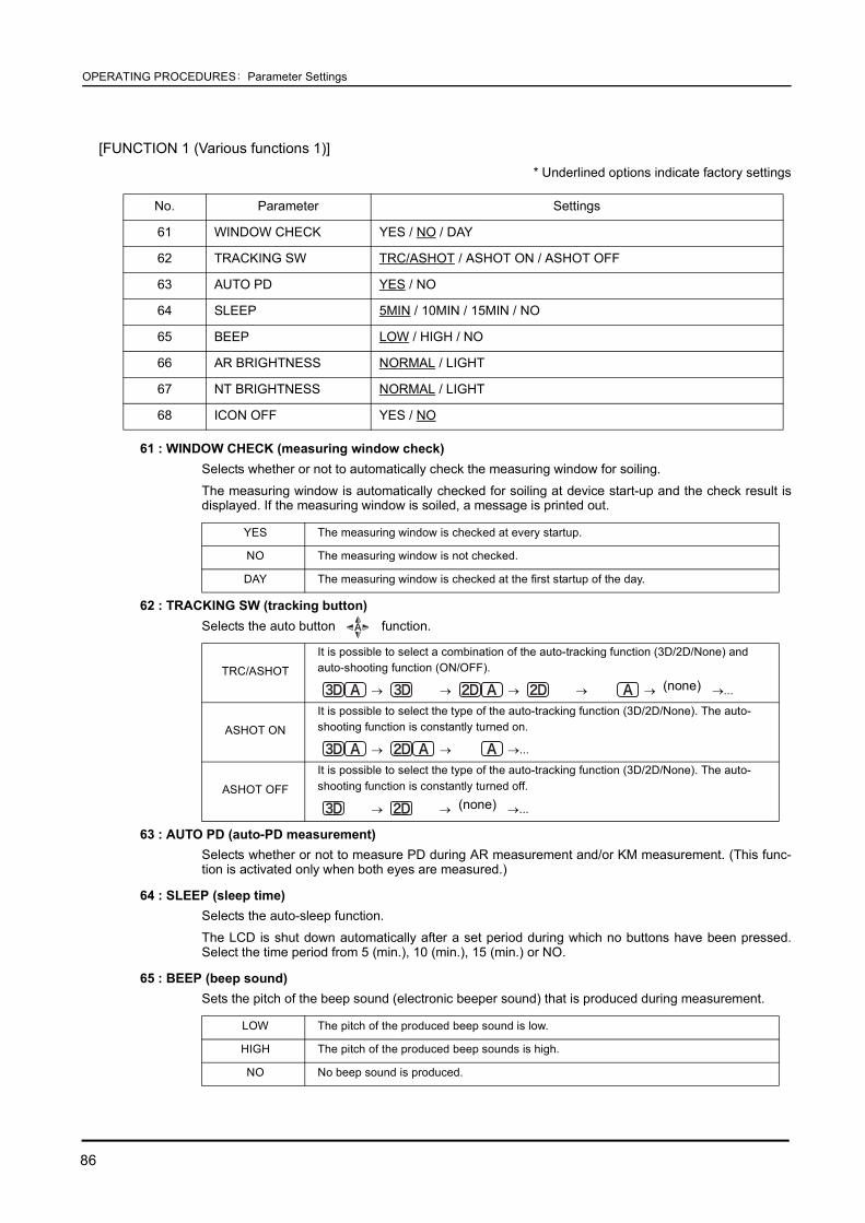
86
OPERATING PROCEDURES: Parameter Settings
[FUNCTION 1 (Various functions 1)]* Underlined options indicate factory settings
61 : WINDOW CHECK (measuring window check)Selects whether or not to automatically check the measuring window for soiling.
The measuring window is automatically checked for soiling at device start-up and the check result isdisplayed. If the measuring window is soiled, a message is printed out.
62 : TRACKING SW (tracking button)Selects the auto button function.
63 : AUTO PD (auto-PD measurement)Selects whether or not to measure PD during AR measurement and/or KM measurement. (This func-tion is activated only when both eyes are measured.)
64 : SLEEP (sleep time)Selects the auto-sleep function.
The LCD is shut down automatically after a set period during which no buttons have been pressed.Select the time period from 5 (min.), 10 (min.), 15 (min.) or NO.
65 : BEEP (beep sound)Sets the pitch of the beep sound (electronic beeper sound) that is produced during measurement.
No. Parameter Settings
61 WINDOW CHECK YES / NO / DAY
62 TRACKING SW TRC/ASHOT / ASHOT ON / ASHOT OFF
63 AUTO PD YES / NO
64 SLEEP 5MIN / 10MIN / 15MIN / NO
65 BEEP LOW / HIGH / NO
66 AR BRIGHTNESS NORMAL / LIGHT
67 NT BRIGHTNESS NORMAL / LIGHT
68 ICON OFF YES / NO
YES The measuring window is checked at every startup.
NO The measuring window is not checked.
DAY The measuring window is checked at the first startup of the day.
TRC/ASHOT
It is possible to select a combination of the auto-tracking function (3D/2D/None) and auto-shooting function (ON/OFF).
→ → → → → →...
ASHOT ON
It is possible to select the type of the auto-tracking function (3D/2D/None). The auto-shooting function is constantly turned on.
→ → →...
ASHOT OFF
It is possible to select the type of the auto-tracking function (3D/2D/None). The auto-shooting function is constantly turned off.
→ → →...
LOW The pitch of the produced beep sound is low.
HIGH The pitch of the produced beep sounds is high.
NO No beep sound is produced.
(none)
(none)

87
OPERATING PROCEDURES: Parameter Settings
2
66 : AR BRIGHTNESS (light intensity of AR measurement screen)Brightness of the LCD screen during the ARK measurement.
Select the brightness from NORMAL or LIGHT.
67 : NT BRIGHTNESS (light intensity of NT measurement screen)Brightness of the LCD screen during the NT measurement.
Select the brightness from NORMAL or LIGHT.
68 : ICON OFF (icon display)Selects whether to display the icon buttons on the measurement screen.
[FUNCTION 2 (Various functions 2)]* Underlined options indicate factory settings
71 : CHANGE MODE (Method of switching the measurement mode)Selection of whether or not to automatically check the air pressure.
The pressure of puffed air is automatically checked during startup and the check result is displayed. If thepressure of the puffed air is abnormal, a message is printed out.
72 : CHANGE MODE (Method of switching the measurement mode)Setting of the method of switching the measurement mode from the R/K measurement to the NT measure-ment in RKT mode.
YES
Touch icons are not displayed.To use each function of the function buttons (except for clear and print), follow the procedure below:
1) Press a function button (except for clear and print) on the measurement screen to display the icons.
2) When icons are displayed, each button functions.
3) Press the clear button or print button to turn off the displayed icons.
NO Touch icons are always displayed.
No. Parameter Settings
71 PRESSURE CHECK YES / NO / DAY
72 CHANGE MODE AUTO / MANUAL
73 CHANGE SPEED LOW / HIGH
74 TARGET TYPE RKT / AR/NT
DAY The air pressure is checked at the first startup of the day.
YES The air pressure is checked at every startup.
NO The air pressure is not checked.
AUTOAfter the completion of the R/K measurement, pull the main body backward on conditionthat “PULL BACK” message is displayed on the screen to switch the mode to NTmeasurement mode.
MANUALEven after the R/K measurement, the measurement mode is not switched to NTmeasurement. To switch to NT measurement mode, pull the main body backward andpress the start button.

88
OPERATING PROCEDURES: Parameter Settings
73 : CHANGE SPEED (Measurement changeover speed)Setting of the time period required when the measurement mode is switched from the R/K measurement tothe NT measurement in RKT mode.
74 : TARGET TYPE (Target type)Selection of the type of the target and focusing indicator that are displayed in NT measurement mode.
[COMMUNICATION (Communication function)]* Underlined options indicate factory settings.
81 : I/F MODE (communication mode)Selects the device to communicate with.
82 : I/F FORMAT (communication format)Selects the format of data to be transmitted.
83 : BAUD-RATESelects the baud-rate (bit transmission speed) for communication.
84 : BIT LENGTHSelects the bit number for a single character used for communication.
85 : CR CODE (line feed code)Selects whether or not to attach CR (carriage return) code at the end of data to be transmitted.
86 : LM DATA PRINT (printing of imported LM data)Selects whether or not to print the data imported from the lensmeter connected to the data input port bythe built-in printer of the ARK-530A/ARK-510A.
When the parameter is set to YES, the data is printed from the TONOREF II printer by pressing theprint button of the lensmeter.
(A lensmeter provided with the function of printing data is needed.)
See the Operator’s Manual of the lensmeter for details.
HIGH About ten seconds
LOW About six seconds
RKT During the R/K and NT measurements, the same focusing indicator is displayed.
AR/NT During the NT measurement, the special focusing indicator is displayed.
No. Parameter Settings
81 I/F MODE NIDEK / NCP10
82 I/F FORMAT ALL / SHORT
83 BAUD-RATE 1200 / 2400 / 4800 / 9600
84 BIT LENGTH 7 / 8
85 CR CODE YES / NO
86 LM DATA PRINT YES / NO
NIDEK Communication with a NIDEK-brand device
NCP10 NCP10-compliant device
ALL All data are transferred.
SHORT Restricted data is transmitted.
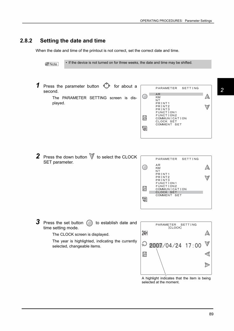
89
OPERATING PROCEDURES: Parameter Settings
2
2.8.2 Setting the date and timeWhen the date and time of the printout is not correct, set the correct date and time.
1 Press the parameter button for about asecond.
The PARAMETER SETTING screen is dis-played.
2 Press the down button to select the CLOCKSET parameter.
3 Press the set button to establish date andtime setting mode.
The CLOCK screen is displayed.
The year is highlighted, indicating the currentlyselected, changeable items.
• If the device is not turned on for three weeks, the date and time may be shifted.
A highlight indicates that the item is beingselected at the moment.

90
OPERATING PROCEDURES: Parameter Settings
4 Press the up button or down button tomove the highlight to an item to be changed.
5 Press the right button or the left button to change the setting.
To change the time format:
6 Repeat Steps 4 to 5 to set the date and time.
7 After entering comments, press the exit button to exit from comment setting mode.As soon as the exit button is pressed, the internal clock is updated to the set date andtime.
The screen is switched back to the PARAMETER SETTING screen.
8 Press the exit button to return to the measurement screen.
Right button Increases the number.
Left button Decreases the number.
/ Change the time format between the 24-hour and 12-hour.
Changes the date format in the order of Y/ M/ D, M/ D/ Y, D/ M/ Y...

91
OPERATING PROCEDURES: Parameter Settings
2
2.8.3 Entering commentsComments to be printed can be changed (factory setting: “NIDEK TONOREF II”).
1 Press the parameter button for about asecond.
The PARAMETER SETTING screen is dis-played.
2 Press the down button to select the COMMENTSET parameter.
3 Press the set button to establish the com-ment setting mode.
The SET COMMENT screen is displayed.
In the lower part of the screen, the currentlyentered comments are displayed.

92
OPERATING PROCEDURES: Parameter Settings
4 Press the right button or left button toselect the position where a character is enteredor changed
The cursor indicates the position where a char-acter is entered or changed.
Up to 24 characters can e entered in two lines.
5 Enter comments with the following buttons.After moving the cursor of the character list to the desired character, press the OK button
to confirm its entry.
The following buttons are available:
6 Repeat Steps 4 to 5 to enter the desired comments.
7 After entering comments, press the exit button to exit from the comment settingmode.
8 Press the exit button to return to the measurement screen.The entered comments are saved.
Moves the current selection to the left in the character table.
Moves the current selection to the right in the character table.
Determines the character to be entered and moves the highlight to the nextdigit.Erases the character at the cursor position and moves the highlight to theprevious digit.
It is also possible to erase characters by entering a space (SP).
Test prints the comment only.
• When the start button is held down with the SET COMMENT screen displayed, comments return to the default setting (“NIDEK TONOREF II”).
Move the cursor to the desired position.

93
3
3. OPERATION WHEN PERIPHERAL DEVICES ARE CONNECTED
The TONOREF II exports data to an external device such as NIDEK motorized refractor (hereafterreferred to as the RT), computer, and Eye Care card system.The TONOREF II also imports data from the NIDEK lensmeter (hereafter referred to as the LM).
3.1 Connecting to the NIDEK Motorized Refractor (RT) or Computer
3.1.1 OutlineAny data on printout can be exported to the RT or a computer.The AR-measured data transmitted to the RT is used as objective data in subjective tests.
Connectable devices: RT-2100 series, RT-5100Data transmitted to a computer can be managed by various database software.
CAUTION • Before connecting cables to devices, turn the devices off and disconnect the powercord from an outlet.
Malfunction may result.
• AR measured data is transmitted through an RS-232C interface.
Objective measurementSubjective measurement
AR data
AR data, KM dataNT data
Data management with data-base softwareData export to RT
NIDEK motorized refractor
Computer
Subjective test guided by former LMdata and objectively-measured data

94
OPERATION WHEN PERIPHERAL DEVICES ARE CONNECTED: Connecting to the NIDEK Motorized Refractor (RT) or Computer
3.1.2 Connecting procedure
1 Connect the RT (or a computer) to the data output port ( ) of the TONOREF IIvia an interface cable (optional).
Connect the cable with the device laid down.
Attach a ferrite core (optional) to the interface cable connector of the TONOREF II.
3.1.3 Operating procedure
1 After measurement, press the print button .Perform the printing process in the standard manner.
See “2.2 Preparation for Measurement (Page 24)”for the measuring method.
See “2.7 Printing (Page 71)” for printing.
2 The TONOREF II automatically transmits data to the RT (or computer).When connected to the RT, the TONOREF II receives the data No. (ID No.) from theRT. When connected to the PC, the data No. (ID No.) is not received.
3 The measured data is printed.
To RT or computer
RS-232C cable (optional)
Ferrite core (optional)
• Disconnect the interface cable while pressing the button on the connector.
When the cable is connected, the button islocated on the underside of the connector.
Button
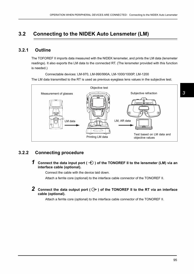
95
OPERATION WHEN PERIPHERAL DEVICES ARE CONNECTED: Connecting to the NIDEK Auto Lensmeter
3
3.2 Connecting to the NIDEK Auto Lensmeter (LM)
3.2.1 OutlineThe TOFOREF II imports data measured with the NIDEK lensmeter, and prints the LM data (lensmeterreadings). It also exports the LM data to the connected RT. (The lensmeter provided with this functionis needed.)
Connectable devices: LM-970, LM-990/990A, LM-1000/1000P, LM-1200The LM data transmitted to the RT is used as previous eyeglass lens values in the subjective test.
3.2.2 Connecting procedure
1 Connect the data input port ( ) of the TONOREF II to the lensmeter (LM) via aninterface cable (optional).
Connect the cable with the device laid down.
Attach a ferrite core (optional) to the interface cable connector of the TONOREF II.
2 Connect the data output port ( ) of the TONOREF II to the RT via an interfacecable (optional).
Attach a ferrite core (optional) to the interface cable connector of the TONOREF II.
Measurement of glasses
Objective test
Subjective refraction
LM data LM, AR data
Printing LM dataTest based on LM data andobjective values

96
OPERATION WHEN PERIPHERAL DEVICES ARE CONNECTED: Connecting to the NIDEK Auto Lensmeter (LM)
3.2.3 Operating procedure
1 After lens measurement with the LM, press the print button on the LM.
2 The TONOREF II receives lensmeter readings from the LM.
3 The LM data is printed and data is transmitted to the RT.
To RT
Interface cable(optional)
To LM
Ferrite cores(optional)
• When the device communicates with the LM, set the communication parameters of each instrument as follows. See the operator’s manual for the setting method of each device.
[Settings of TONOREF II]83. BAUD-RATE = 960084. BIT LENGTH = 886. LM DATA PRINT = YES
[Settings of NIDEK lensmeter]PRINTER = COM PRINTRS-232C = NIDEKBaud Rate = 9600Parity = OddData Bits = 8Stop Bits = 1

97
OPERATION WHEN PERIPHERAL DEVICES ARE CONNECTED: Connecting to the Eye Care Card System
3
3.3 Connecting to the Eye Care Card System
3.3.1 OutlineData transfer by way of the Eye Care card using the optional Eye Care card system “EyeCa-RW” isexplained.The Eye Care card system should be connected to the data output port ( ) provided at the bottomof the device.For the DIP switch settings, only set SW3 of the DIP switchpack of the Eye Care card system locatedat the bottom to the “ON” position.
3.3.2 Method of connection
1 Connect the interface cable of the EyeCa-RW to the data output port ( ).
In the case of AUTO OPTOMETRY SYSTEM COS-550:
EyeCa-RWEye Care card
EyeCa-RW
Objectively measured data
TONOREF II
EyeCa-RW
Interface cable(optional)

98
OPERATION WHEN PERIPHERAL DEVICES ARE CONNECTED: Connecting to the Eye Care Card System
3.3.3 Transferring data with the EyeCa-RWThe procedure for writing data to the Eye Care card differs depending on whether the measured datais printed or not.
When printing measured data
1 Insert the Eye Care card into the TONOREF II on condition that the TONOREF IIhas no measured data in the internal memory.
The EyeCa-RW emits a short beep and the access indicator illuminates in green.
If the TONOREF II has not measured data in its memory, the memory indicator of theTONOREF II is shut off.
2 Perform measurements.
3 Press the print button .Follow the same procedure as the normal printing procedure.
The access indicator changes to the orange one, and the data is written to the Eye Carecard.
After the data has been written successfully, the EyeCa-RW emits a short beep and theaccess indicator flashes in green.
See “2.7 Printing (Page 71)” for the printing procedure.
4 After the access indicator of the EyeCa-RW has changed to the green flashingone, eject the Eye Care card.
Eye Care cardIC card Reader/WriterEyeCa-RW
Access indicator
• Refer to the Operator's Manual supplied with the EyeCa-RW for the other procedures.

99
OPERATION WHEN PERIPHERAL DEVICES ARE CONNECTED: Connecting to the Eye Care Card System
3
When not printing measured data
Set the 39. PRINT parameter to “MANUAL” or “NO” in advance.See “2.8 Parameter Settings (Page 76)” for details.
1 After measurements, insert the Eye Care card.The EyeCa-RW emits a short beep and the access indicator illuminates in green. Theaccess indicator changes to the orange one, and the data is written to the Eye Care card.
After the data has been written successfully, the EyeCa-RW emits a short beep and theaccess indicator flashes in green.
2 After the access indicator of the EyeCa-RW starts flashing in green, eject the EyeCare card.
3.3.4 Erasing data on the Eye Care cardAll the data on the Eye Care card is erased.
1 Press the clear switch of the EyeCa-RW forabout a second.
The EyeCa-RW emits a short beep and theaccess indicator is lit in red.
2 Insert the Eye Care card.The access indicator is lit in orange and all the data on the Eye Care card is erased.
If the data has been erased, the EyeCa-RW emits a longer beep and the access indicatorflashes in green.
• Never eject the Eye Care card while it is being accessed.While the card is being accessed, the access indicator is lit in orange.
The access indicator flashing in orange indicates an error occurrence. In this case, the card canbe ejected.
When trying to eject the card while it is being accessed, data will not be written successfully andthe Eye Care card may be irreparably damaged.
Clear switch

100
OPERATION WHEN PERIPHERAL DEVICES ARE CONNECTED: Connecting to the Eye Care Card System

101
4
4. MAINTENANCE
4.1 Troubleshooting
In the event that the device does not work correctly, correct the problem according to the followingtable before contacting NIDEK or your authorized distributor.
Symptom Remedy
The LCD display does not turn on. • The power cord may not be correctly connected.
Reconnect it securely. • The power switch may not have been turn on. Check the power switch.
The LCD display does not turn on (not clear) even though the power is on.
• The sleep function may have been executed. Try to recover the monitor ON condition by pressing any button.
The screen disappears suddenly. • Sleep mode may have been activated. Press any button to exit from
sleep mode.
The main body cannot be moved laterally.
• The locking lever may be locked.Flip up the locking lever.
Data is not printed out.
• Check the printer paper. If the paper has been used up, load new printer paper.
• The 31. PRINT parameter may be set to NO.Reset the parameter.
The printer does operate, however, printed results cannot be obtained.
• The printer paper may be loaded with the wrong side up.Set it with the correct side up.
When the power is turned on or the
print button is pressed, “ERROR” or “NO PAPER” appears even though printer paper is loaded.
• Check that the printer cover is securely closed.Open the printer cover and close it securely.
• The print button may have been pressed too soon after the printer cover was closed.
After the printer cover is closed, it takes time for the printer to be ready.
Printer paper does not feed.
• Printer paper may be loaded in a tilted position or the core of the roll may not be placed properly.
Open the printer cover and make sure that printer paper is properly loaded.

102
MAINTENANCE: Troubleshooting
If the symptom cannot be corrected with the above actions, contact NIDEK or your authorized distributor.
The auto-tracking function or auto-shooting function does not work.
• The auto-tracking function or auto-shooting function may not have been turned on.
Turn them on with the auto button . • Room illumination may be reflecting on the cornea.
Change the location and try measurement again. • The auto-tracking function or auto-shooting function may not work on
some eyes such as keratoconus or recently-operated cornea.In such cases, turn off the auto-tracking function and start measurement.
• The patient who has substantial ocular ataxia or who cannot fixate his or her eyes, the auto-tracking function may not work.
In such cases, turn off the auto-tracking function and start measurement.
• If the device is installed in the vicinity of a window where the device is exposed to sunshine, light interference may adversely affect these functions.
Change the installed position of the device and start measurement again.
“PD ERR” is displayed on the screen. • Make sure that the PD measuring window is not blocked.
A measurement error appears.
• The patient may have blinked during measurement.Instruct the patient not to blink and try measurement again.
• The eyelid or eyelashes may obstruct measurement.Instruct the patient to open his/her eye wider.If the patient cannot open wider, lift the patient’s lid, paying attention not to press against the eyeball.
• The pupil may be too small for measurement.Have the patient sit in a dark room for a while until the pupil enlarges enough and try measurement again.
• The data may exceed the measurable limit.
Measurement values differ. (Measurement values do not differ when measuring the model eye.)
• The patient may be moving their visual line.Instruct the patient to look the fixiation chart.For AR, KM measurement: Look the center of the scenery chart.For NT measurement: Look the fixiation lamp.
• For patients who have difficulty maintaining their visual line, turn OFF the auto shooting function and manually press the start switch to measure when the visual line is proper.
“CHECK MEASURING WINDOW.” is printed out at device start-up.
• Clean the measuring window.See “4.6.1 Cleaning the measuring window” (page 111).
• If the measuring window is not dirty, make sure that the measuring window is not blocked at device start-up.
Errors such as "PRESSURE PEAK ERROR", “PRESSURE SLOPE ERROR" or “NO PRESURE UP" are printed out at device start-up.
• Turn off the power while in Measurement mode and clean the contamination from air nozzle.
・ See “4.6.2 Cleaning the air nozzle” (page 113).
Symptom Remedy

103
MAINTENANCE: Error Messages and Countermeasures
4
4.2 Error Messages and Countermeasures
If one of the following error codes is displayed on the screen or printed out, follow the suggestions inthe cause and countermeasure column.The error code, detailed indications and serial number of your device are helpful in proper servicing.
Error code Cause and countermeasure
ERR001
• Data error of backup memory (EEPROM)Data loss due to exogenous noise such as static electricity or malfunction of electric circuit board or EEPROM on the electric circuit board is probable.
• If the same error code is displayed again even after the device is turned off and on again, shut off the device and contact NIDEK or your authorized distributor.
ERR002
• Date and time setting errorThe built-in battery has been discharged after about one month or longer of nonuse, and the date and time settings went wrong, or malfunction of electric circuit board or timer IC on the electric circuit board is probable.
• If the same error code is displayed again even after the date and time are reset in the parameter setting mode, shut off the device and contact NIDEK or your authorized distributor.
PD ERR
• Error related to the PD measurementMalfunction of the PD sensor or LED is probable.
• Make sure that the PD measuring window is not blocked. • Shut off the device and contact NIDEK or your authorized distributor.
ERR011 • Error related to control signals for communication (output port)
Ensure that the interface cable is properly connected to the output port. • Also ensure that the communication parameters are properly set.
ERR012 • Error related to control signals for communication (output port)
Ensure that the interface cable is properly connected to the output port. • Also ensure that the communication parameters are properly set.
ERR013 • Error related to communication data (output port)
Ensure that the interface cable is properly connected to the output port. • Also ensure that the communication parameters are properly set.
ERR014 • Error related to communication data (output port)
Ensure that the interface cable is properly connected to the output port. • Also ensure that the parameters related to communication are properly set.
ERR015 • Error related to communication data (output port)
Ensure that the interface cable is properly connected to the output port. • Also ensure that the communication parameters are properly set.
ERR016 • Error related to communication data (output port)
Ensure that the interface cable is properly connected to the output port. • Also ensure that the communication parameters are properly set.
ERR017 • Error related to communication data (output port)
Ensure that the interface cable is properly connected to the output port. • Also ensure that the communication parameters are properly set.
ERR018 • Error related to communication data (output port)
Ensure that the interface cable is properly connected to the output port. • Also ensure that the communication are properly set.
NO DAT • Error related to communication data (output port)
Ensure that the interface cable is properly connected to the output port. • Also ensure that the communication parameters are properly set.

104
MAINTENANCE: Error Messages and Countermeasures
ERR021 • Error related to control signals for communication (input port)
Ensure that the interface cable is properly connected to the input port. • Also ensure that the communication parameters are properly set.
ERR022 • Error related to control signals for communication (input port)
Ensure that the interface cable is properly connected to the input port. • Also ensure that the communication parameters are properly set.
ERR023 • Error related to control signals for communication (input port)
Ensure that the interface cable is properly connected to the input port. • Also ensure that the communication parameters are properly set.
ERR024 • Error related to control signals for communication (input port)
Ensure that the interface cable is properly connected to the input port. • Also ensure that the communication parameters are properly set.
ERR025 • Error related to control signals for communication (input port)
Ensure that the interface cable is properly connected to the input port. • Also ensure that the communication parameters are properly set.
ERR026 • Error related to communication data (output port)
Ensure that the interface cable is properly connected to the output port. • Also ensure that the communication parameters are properly set.
ERR027 • Error related to communication data (output port)
Ensure that the interface cable is properly connected to the output port. • Also ensure that the communication parameters are properly set.
ERR028 • Error related to communication data (output port)
Ensure that the interface cable is properly connected to the output port. • Also ensure that the communication parameters are properly set.
ERR031
• Error related to the up-and-down trackingMalfunction of the up-and-down motor, up-and-down sensor, electric circuit board, or break in cables is probable.
• Shut off the device and contact NIDEK or your authorized distributor.
ERR032
• Error related to left-to-right trackingMalfunction of the right-to-left motor, right-to-left sensor, electric circuit board, or break in cables is probable.
• Shut off the device and contact NIDEK or your authorized distributor.
ERR033
• Error related to the back-and-forth trackingMalfunction of the back-and-forth motor, back-and-forth sensor, electric circuit, or break in cables is probable.
• Shut off the device and contact NIDEK or your authorized distributor.
ERR034
• Error related to the motorized chinrestMalfunction for the chinrest motor, motorized chinrest sensor, or electric circuit board, or break in cables is probable.
• Shut off the device and contact NIDEK or your authorized distributor.
NO PAPER
• Error related to the printerIf the printer is short of paper, refill paper.If the printer cover is open, close it securely.
• If the same error code is displayed even after the replacement of printer paper roll, malfunction of the printer, electric circuit board, or break in cables is probable.Shut off the device and contact NIDEK or your authorized distributor.
Error code Cause and countermeasure
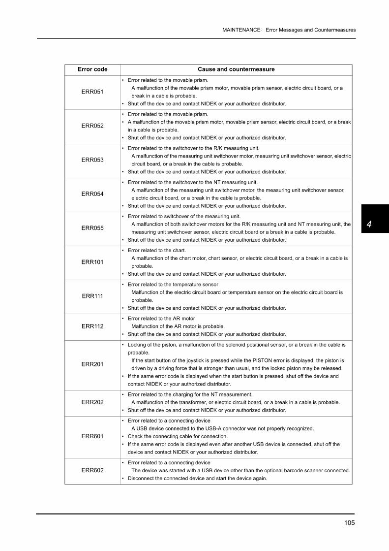
105
MAINTENANCE: Error Messages and Countermeasures
4
ERR051
• Error related to the movable prism.A malfunction of the movable prism motor, movable prism sensor, electric circuit board, or a break in a cable is probable.
• Shut off the device and contact NIDEK or your authorized distributor.
ERR052
• Error related to the movable prism. • A malfunction of the movable prism motor, movable prism sensor, electric circuit board, or a break
in a cable is probable. • Shut off the device and contact NIDEK or your authorized distributor.
ERR053
• Error related to the switchover to the R/K measuring unit.A malfunction of the measuring unit switchover motor, meausring unit switchover sensor, electric circuit board, or a break in the cable is probable.
• Shut off the device and contact NIDEK or your authorized distributor.
ERR054
• Error related to the switchover to the NT measuring unit.A malfunciton of the measuring unit switchover motor, the measuring unit switchover sensor, electric circuit board, or a break in the cable is probable.
• Shut off the device and contact NIDEK or your authorized distributor.
ERR055
• Error related to switchover of the measuring unit.A malfunction of both switchover motors for the R/K measuring unit and NT measuring unit, the measuring unit switchover sensor, electric circuit board or a break in a cable is probable.
• Shut off the device and contact NIDEK or your authorized distributor.
ERR101
• Error related to the chart.A malfunction of the chart motor, chart sensor, or electric circuit board, or a break in a cable is probable.
• Shut off the device and contact NIDEK or your authorized distributor.
ERR111
• Error related to the temperature sensorMalfunction of the electric circuit board or temperature sensor on the electric circuit board is probable.
• Shut off the device and contact NIDEK or your authorized distributor.
ERR112 • Error related to the AR motor
Malfunction of the AR motor is probable. • Shut off the device and contact NIDEK or your authorized distributor.
ERR201
• Locking of the piston, a malfunction of the solenoid positional sensor, or a break in the cable is probable.
If the start button of the joystick is pressed while the PISTON error is displayed, the piston is driven by a driving force that is stronger than usual, and the locked piston may be released.
• If the same error code is displayed when the start button is pressed, shut off the device and contact NIDEK or your authorized distributor.
ERR202 • Error related to the charging for the NT measurement.
A malfunction of the transformer, or electric circuit board, or a break in a cable is probable. • Shut off the device and contact NIDEK or your authorized distributor.
ERR601
• Error related to a connecting deviceA USB device connected to the USB-A connector was not properly recognized.
• Check the connecting cable for connection. • If the same error code is displayed even after another USB device is connected, shut off the
device and contact NIDEK or your authorized distributor.
ERR602 • Error related to a connecting device
The device was started with a USB device other than the optional barcode scanner connected. • Disconnect the connected device and start the device again.
Error code Cause and countermeasure

106
MAINTENANCE: Replacing Printer Paper
4.3 Replacing Printer Paper
When a red line appears on the side of printer paper, it means that paper is running short.In such a case, stop using the printer and replace printer paper with new one.
1 Press the cover open button to open the printercover.
2 Remove the used printer paper.
• Do not run the printer when printer paper is not loaded.It may ruin the printer head.
• Do not pull the paper in the printer forcefully.This may cause malfunction of the printer.
CAUTION • Do not touch the printer head at the top of the opened printer cover.The printer head is hot right after printing and you may get burned.

107
MAINTENANCE: Replacing Printer Paper
4
3 Insert new printer paper.Load printer paper as shown in the picture on theright.
Set printer paper so that its end is exposed from thecover.
4 Push the printer cover toward the main body.Press the printer cover at both ends to close thecover securely.
• If the roll is loaded in such a way that paper becomes upside down, it is not possible to print data out.
• Be sure that printer paper is not loaded in a tilted position, the core of the roll is properly placed, or there is no slack in the roll.
Printer paper may not be fed properly.
• Be sure that the cover is securely closed.If the cover is insecurely closed, the auto cutter may not operate properly. In addition, when theprint button is pressed, “ERROR” or “NO PAPER” may appear and printing will not occur.
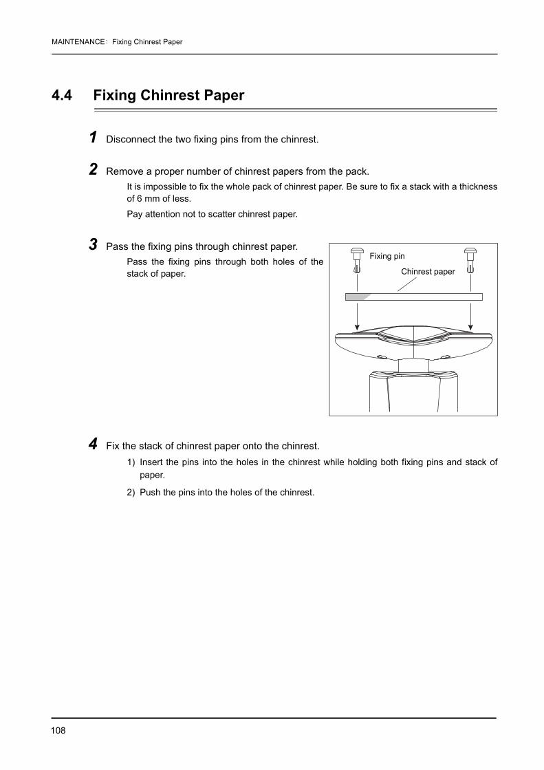
108
MAINTENANCE: Fixing Chinrest Paper
4.4 Fixing Chinrest Paper
1 Disconnect the two fixing pins from the chinrest.
2 Remove a proper number of chinrest papers from the pack.It is impossible to fix the whole pack of chinrest paper. Be sure to fix a stack with a thicknessof 6 mm of less.
Pay attention not to scatter chinrest paper.
3 Pass the fixing pins through chinrest paper.Pass the fixing pins through both holes of thestack of paper.
4 Fix the stack of chinrest paper onto the chinrest.1) Insert the pins into the holes in the chinrest while holding both fixing pins and stack of
paper.
2) Push the pins into the holes of the chinrest.
Fixing pin
Chinrest paper

109
MAINTENANCE: Checking the AR/KM Measurement Accuracy
4
4.5 Checking the AR/KM Measurement Accuracy
To check the accuracy of measured data, use the provided spherical model eye for R/K measurement.The spherical model eye is incorporated with a contact lens holder.
1 Remove the two fixing pins and remove thestack of chinrest paper from the chinrest.
2 Remove the cap from the spherical model eyeand put the model eye on the chinrest with itslens toward the measuring window and theninsert the fixing pins.
Check the lens surface of the model eye forsoiling.
3 Align the level of the spherical model eye for R/K measurement with the eye level markerwith the chinrest up/down button or .
4 Set the 1. STEP parameter to 0.01 D.See “2.8 Parameter Settings” (page 76) for the parameter setting method.
5 Perform AR and KM measurements in the same manner as normal AR and KM mea-surements.
• If the measured result is higher than the value indicated on the model eye, contact NIDEK or your authorized distributor.
• Always store the model eye with the cap on.If the lens surface is soiled or flawed, measurement accuracy cannot be properly checked.

110
MAINTENANCE: Checking the AR/KM Measurement Accuracy
Values marked on the labels of the spherical model eye
Vertex distanceDiopter (Unit: D)
Corneal curvature radius(Unit: mm)
• When the vertex distance is set to a value other than 12 mm (US: 13.75 mm), set the 2. VERTEX D. parameter to 12 mm (13.75 mm) before performing AR measurement.

111
MAINTENANCE: Cleaning
4
4.6 Cleaning
When the cover or panel of the device becomes dirty, wipe with a soft cloth. For stubborn dirt, immersethe cloth in a neutral detergent, wring well, and wipe. Finally wipe with a dry and soft cloth.
4.6.1 Cleaning the measuring windowWhen the measuring window gets fingerprints or dust on it, the reliability of the measured value isimpaired substantially. Check for dirt on the measuring window before use, and then clean it if it isdirty.The measuring window lens does not usually get soiled through normal use because it is recessed.Only clean it when “CHECK MEASURING WINDOW.” is displayed or the lens is soiled.
1 Display the R/K measurement screen.
2 Blow off dust on the measuring window with a blower.
3 Wrap lens cleaning paper around a thin sticksuch as a chopstick (or cotton swab) and wipethe lens of the measuring window with a materialmoistened with alcohol.
4 Wipe off the glass of the mire ring around the measuring window using a gauze or suchdampened with alcohol.
CAUTION • Never use an organic solvent such as paint thinner.It may ruin the surface of the device.
• Lightly wipe the exterior of the LCD display. Do not press the LCD display using anobject with a hard tip. In addition, keep magnetic objects away from the LCD display.
Scratches or failure of the LCD display may result.
• Never use a sponge or cloth soaked in water.The water may leak into the inside of the device and cause device failure.
• Use a thin stick which does not damage glass lenses.
• Wipe lightly from the center of the measuring window to the outside in a circular motion.
Wrap cleaning paper around the tip.

112
MAINTENANCE: Cleaning
5 Check if the window is cleaned using a penlight. If not, clean it again with new cleaningpaper.
Apply light with a penlight and change the view angle to check the dirt clearly.
Measuring window
Mirre ring part
• When the 61. WINDOW CHECK parameter is set to YES or DAY, the measuring window is checked whether it is soiled at device start-up.
YES⇒ The measuring window is checked at every start-up.
DAY⇒ The measuring window is checked at the first start-up of the day.
• When “CHECK MEASURING WINDOW.” is printed, clean the measuring window.
• At device start-up, do not stand or put objects in front of the measuring window.If something blocks the front of the measuring window within the range of 1 m, the measuring win-dow may not be checked correctly.

113
MAINTENANCE: Cleaning
4
4.6.2 Cleaning the air nozzle
1 Display the NT measuring screen.
2 Check the glass part of the air nozzle from an oblique direction for dust, soiling, etc.
3 Blow the dust, foreign particles etc. off with a blower if they are settled.
4 Gently wipe the glass part with a cotton swab dampened with alcohol.
5 Check the glass part for soiling again.
• Pay attention not to let dust or foreign particles into the air nozzle during cleaning.
Glass part Hole of the air nozzle
CAUTION • Gently wipe the air nozzle without rubbing or without wiping it with foreign particles settled.The glass part may be scratched.

114
MAINTENANCE: List of Replacement Parts
4.6.3 Cleaning the printerAfter repeated usage, the paper slot of the auto cutter of the printer may become soiled with powderypaper. If the powdery paper settles, malfunction of the auto cutter may result. It must be cleaned then.
1 Open the printer cover and remove the printerpaper roll.
See “4.3 Replacing Printer Paper” (page 106).
2 Apply the nozzle of a vacuum cleaner to the auto cutter to remove powdery paper.Never blow off powdery paper with a blower. If powdery paper settles on the internal workingstructure, malfunction may result.
3 Supply the printer paper as it was.
4.7 List of Replacement Parts
* After replacing consumables, restock them.
Auto cutter
Part name Part number Note
Printer paper 80620-00001 Width 58 mm, Length 25 m
Chinrest paper 32903-M047 Pack of chinrest paper
115
5
5. SPECIFICATIONS AND ACCESSORIES
5.1 Classifications
[Classification under the provision of 93/42EEC (MDD)] Class IIa
The TONOREF II is classified as a Class IIa device.
[Form of protection against electrical shock] Class I
The TONOREF II is classified as a Class I device.
A Class I is a device in which the protection against electric shock does not rely on basicinsulation only, but which includes an additional safety precaution in such a way that meansare provided for the connection of the device to the protective (ground) conductor in the fixedwiring of the installation in such a way that accessible metal parts can not become live in theevent of a failure in the basic insulation.
Use a power outlet which is equipped with a grounding terminal.
[Degree of protection against electrical shock] Type B applied part
The TONOREF II is classified as a device with a Type B Applied Part.
A Type B Applied Part provides a particular degree of protection against electrical shock,particularly regarding the following:
- allowable leakage currents
- reliability of the protective earth connection (if present)
[Degree of protection against liquid entry] IPX0
The TONOREF II is classified as a normal device, as such provides only minimal protectionagainst liquid intrusion.
Avoid exposing water to the device.
[Degree of protection against flammability]
The TONOREF II should be used in an environment where no flammable anesthetics and/orflammable cleaning agents are present.
Do not operate the device near flammable type materials.
[Method (s) of sterilization or disinfection recommended by the manufacturer]
The TONOREF II is a device that does not contain parts that need disinfecting.
[Mode of operation]
The TONOREF II is a continuous operation device.
[Mode of transport]
Stationary equipment.
116
SPECIFICATIONS AND ACCESSORIES: Safety Features
5.2 Safety Features
To ensure safe use, the device is provided with the following safety features.
<Main body position detection switch>The switch detects if the main body is fully pulled toward the operator.
Unless the switch is turned on, the switchover between the R/K measuring unit and NT mea-suring unit is disabled.
<Patient sensor>This sensor detects if the patient's chin is placed on the chinrest during the up-and-downmovement of the chinrest.
While the patient is being detected by the sensor, the chinrest is not initialized.
<Safety stopper>For safety, this stopper provides a safety space so that the air nozzle does not touch apatient’s eye during measurements.
The amount of space needed for safety depends on the patient. Change the position of thestopper for each patient to ensure the proper amount of space for safety.

117
SPECIFICATIONS AND ACCESSORIES: Specifications
5
5.3 Specifications
Measurement of refractive error (AR measurement)
Measurement of corneal curvature (KM measurement)
• Spherical power (S)-30.00 to +25.00 D (V.D.=12 mm)0.01/ 0.12/ 0.25 D increments
• Cylindrical power (C)0 to ±12.00 D0.01/ 0.12/ 0.25 D increments
• Cylinder axis (A) 0° to 180°1°/ 5° increments
• Vertex distance 0 mm/10.5 mm/12 mm/13.75 mm/15 mm/16.5 mm
• Minimum pupil diameter measurableφ2 mm
• Relaxation of accommodating eyeAuto-fogging system
• Chart Scenery chart
• Accuracy The accuracy specifications are based on the results of eye model testing performed inaccordance with ISO10342, Ophthalmic Instruments-Eye Refractometers.
• Corneal curvature radius (R1, R2, AVE)5.00 to 13.00 mm0.01 mm incrementsAccuracy:±0.05 mm
• Corneal refractive power (R1, R2, AVE)25.96 to 67.50 D (n=1.3375)0.01/0.12/0.25 D incrementsn = 1.3375/ 1.336/ 1.332
• Corneal cylindrical power (CYL)0 D to ±12.00 D0.01/0.12/0.25 D increments
Criterion Measurable rangeMaximum scale
interval Test devicea Tolerance
Spherical vertex power
-15 D to +15 D(Maximum meridional
vertex power)0.25 D
0 D, ±5 D, ±10 D ±0.25 D
±15 D ±0.50 D
Cylindrical vertex power
0 D to 6 D 0.25 D Sph: approx. 0 DCyl: -3 D
Axis: 0°, 90°
±0.25 D
Cylinder axisb for cylinder power
0° to 180° 1° ±5°
a The refractive error of the test device shall not differ by more than 1.0 from the nominal value above.b Cylinder axis shall be indicated as specified in ISO8429.

118
SPECIFICATIONS AND ACCESSORIES: Specifications
PD measurement
CS measurement
PS measurement
Measurement of intraocular pressure (NT measurement)
Working range of auto-tracking
Movable range of horizontal direction (by joystick)
• Cylinder axis (A)0° to 180°1°/ 5° increments
• Chart Scenery chart
• Measurable range 30 to 85 mm(Near PD: 28 to 80 mm, Near working distance= 40 cm)1 mm increments
• Measurable range 10.0 to 14.0 mm0.1 mm increments
• Measurable range 1.0 to 10.0 mm0.1 mm increments
• Measurable range 1 to 60 mmHg1 mmHg increments
• Measurement range APC40, APC60, 40, 60
• Working distance 11 mm
• Chart Fixation target: Green (Selectable between the bilking target and continuously-lit target)
• Up and down ±15 mm
• Right and left ±5 mm
• Back and forth ±5 mm
• Back and forth 36 mm or more
• Right and left 85 mm or more

119
SPECIFICATIONS AND ACCESSORIES: Specifications
5
Other functions
Dimensions and weight
Environmental conditions (during use)
Environmental conditions (during transport and storage)
Others
• Alignment/observation method 5.7-inch color LCD display
• Printer Thermal line printer with auto cutterWidth 58 mm
• Interface connectorsRS-232C: 2 ports (IN/OUT)USB: 1 port
• Dimensions 260 (W) × 481 (D) × 505 (H) mm
• Weight 23 kg
• Power source AC 100 to 240 V ±10% 50/60 Hz
• Power consumption 100 VA
• Temperature +10 to +35°C
• Humidity 30 to 75% (No condensation)
• Atmospheric pressure 800 to 1060 hPa
• Temperature -10 to +55°C
• Humidity 10 to 95% (No condensation)
• Atmospheric pressure 700 to 1060 hPa
• Installation categoryII (OVERVOLTAGE CATEGORIES)
• Pollution degree 2 (IEC60664)
• Packing unit 1 unit

120
SPECIFICATIONS AND ACCESSORIES: Standard Configuration
5.4 Standard Configuration
5.4.1 Standard accessories
5.4.2 Optional accessories
• Printer paper 3 rolls
• Power cord 1 unit
• Dust cover 1 unit
• Model eye for R/K measurement/ contact lens (CL)holder (Integral type)
1 set
• Fixing pins for chinrest paper 2 units
• Pack of chinrest paper 1 unit
• Operator’s manual 1 volume
• Eye Care card system
• Interface cable

121
6
6. EMC (ELECTROMAGNETIC COMPATIBILITY)
The Electromagnetic Compatibility Directive sets the essential requirements for electrical andelectronic equipment that may disturb or even be disturbed by other equipment. The TONOREF IIcomplies with these requirements as tabled below. Follow the guidance on the tables for use of thedevice in the electromagnetic environment.
EMC (IEC 60601-1-2: 2001)Guidance and manufacturer's declaration - electromagnetic emissions
The TONOREF II is intended for use in the electromagnetic environment specified below. The customer or the user of the TONOREF II should assure that it is used in such an environment.
Emissions test Compliance Electromagnetic environment - guidance
RF emissionsCISPR 11
Group 1 The TONOREF II uses RF energy only for its internal function. Therefore, its RF emissions are very low and are not likely to cause any interference in nearby electronic equipment.
RF emissionsCISPR 11
Class A The TONOREF II is suitable for use in all establishments other than domestic and those directly connected to the public low-voltage power supply network that supplies buildings used for domestic purposes.
Harmonic emissionsIEC 61000-3-2
Class A
Voltage fluctuations/Flicker emissionsIEC 61000-3-3
Complies

122
EMC (ELECTROMAGNETIC COMPATIBILITY)
Guidance and manufacturer's declaration - electromagnetic immunity
The TONOREF II is intended for use in the electromagnetic environment specified below. The customer or the user of the TONOREF II should assure that it is used in such an environment.
Immunity test IEC 60601 test level Compliance level Electromagnetic environment - guidance
Electrostatic Discharge (ESD) IEC 61000-4-2
±6kV contact±8kV air
±6kV contact±8kV air
Floor should be wood, concrete or ceramic tile. If floors are covered with synthetic material, the relative humidity should be at least 30%.
Electrical fast transient/burstIEC 61000-4-4
±2kVfor power supply lines±1kVfor input/output lines
±2kVfor power supply lines±1kVfor input/output lines
Mains power quality should be that of a typical commercial or hospital environment.
SurgeIEC 61000-4-5
±1kVdifferential mode±2kVcommon mode
±1kVdifferential mode±2kVcommon mode
Mains power quality should be that of a typical commercial or hospital environment.
Voltage, dips, short interruptions and voltage variations on power supply input linesIEC 61000-4-11
<5% UT
(>95% dip in UT)for 0,5 cycle40% UT
(60% dip in UT)for 5 cycles70% UT
(30% dip in UT)for 25 cycles< 5% UT
(> 95% dip in UT)for 5 sec
<5% UT
(> 95% dip in UT)for 0,5 cycle40% UT
(60% dip in UT)for 5 cycles70% UT
(30% dip in UT)for 25 cycles < 5% UT
(> 95% dip in UT)for 5 sec
Mains power quality should be that of a typical commercial or hospital environment. If the user of the TONOREF II requires continued operation during power mains interruptions, it is recommended that the TONOREF II be powered from an uninterruptible power supply or a battery.
Power frequency (50/60Hz) magnetic fieldIEC 61000-4-8
3 A/m 3 A/m Power frequency magnetic fields should be at levels characteristic of a typical location in a typical commercial or hospital environment.
NOTE UT is the a.c. mains voltage prior to application of the test level.
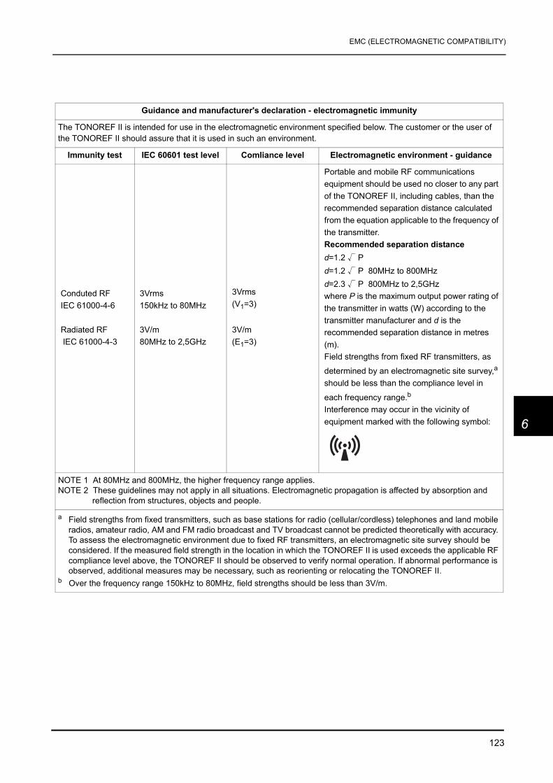
123
EMC (ELECTROMAGNETIC COMPATIBILITY)
6
Guidance and manufacturer's declaration - electromagnetic immunity
The TONOREF II is intended for use in the electromagnetic environment specified below. The customer or the user of the TONOREF II should assure that it is used in such an environment.
Immunity test IEC 60601 test level Comliance level Electromagnetic environment - guidance
Conduted RF IEC 61000-4-6
Radiated RF IEC 61000-4-3
3Vrms150kHz to 80MHz
3V/m80MHz to 2,5GHz
3Vrms(V1=3)
3V/m(E1=3)
Portable and mobile RF communications equipment should be used no closer to any part of the TONOREF II, including cables, than the recommended separation distance calculated from the equation applicable to the frequency of the transmitter.Recommended separation distanced=1.2 √ Pd=1.2 √ P 80MHz to 800MHzd=2.3 √ P 800MHz to 2,5GHzwhere P is the maximum output power rating of the transmitter in watts (W) according to the transmitter manufacturer and d is the recommended separation distance in metres (m).Field strengths from fixed RF transmitters, as
determined by an electromagnetic site survey,a should be less than the compliance level in
each frequency range.b Interference may occur in the vicinity of equipment marked with the following symbol:
NOTE 1 At 80MHz and 800MHz, the higher frequency range applies.NOTE 2 These guidelines may not apply in all situations. Electromagnetic propagation is affected by absorption and
reflection from structures, objects and people.
a Field strengths from fixed transmitters, such as base stations for radio (cellular/cordless) telephones and land mobile radios, amateur radio, AM and FM radio broadcast and TV broadcast cannot be predicted theoretically with accuracy. To assess the electromagnetic environment due to fixed RF transmitters, an electromagnetic site survey should be considered. If the measured field strength in the location in which the TONOREF II is used exceeds the applicable RF compliance level above, the TONOREF II should be observed to verify normal operation. If abnormal performance is observed, additional measures may be necessary, such as reorienting or relocating the TONOREF II.
b Over the frequency range 150kHz to 80MHz, field strengths should be less than 3V/m.

124
EMC (ELECTROMAGNETIC COMPATIBILITY)
Recommended separation distances between portable and mobile RF communications equipment and the TONOREF II
The TONOREF II is intended for use in an electromagnetic environment in which radiated RF disturbances are controlled. The customer or the user of the TONOREF II can help prevent electromagnetic interference by maintaining a minimum distance between portable and mobile RF communications equipment (transmitters) and the TONOREF II as recommended below, according to the maximum output power of the communications equipment.
Rated maximum output power of transmitter
W
Separation distance according to frequency of transmitterm
150kHz to 80MHzd=1.2 √ P
80MHz to 800MHzd=1.2 √ P
800MHz to 2,5GHzd=2.3 √ P
0.01 0.12 0.12 0.23
0.1 0.38 0.38 0.73
1 1.2 1.2 2.3
10 3.8 3.8 7.3
100 12 12 23
For transmitters rated at a maximum output power not listed above, the recommended separation distance d in metres (m) can be estimated using the equation applicable to the frequency of the transmitter, where P is the maximum output power rating of the transmitter in watts (W) according to the transmitter manufacturer. NOTE 1 At 80MHz and 800MHz, the separation distance for the higher frequency range applies.NOTE 2 These guidelines may not apply in all situations. Electromagnetic propagation is affected by
absorption and reflection from structures, objects and people.

125
7
7. GLOSSARY
Terminology related to the AR/KM measurement
AI mode
In this mode, the measurement is automatically completed after three or more measure-ments if the data is stable without variations in the AR measurement.
When unstable data is included, additional measurements are performed until stable data isobtained.
AR median values and KM median values
The central value of the measurements which are put in order in the computer. The latestvalues are selected when the number of the measured data is two or less.
Auto-shooting
This function automatically starts measurements as soon as the device is best aligned andfocused on the eye.
Auto-tracking, Auto-focusing
A function where the device automatically controls the up, down, right, and left movementsfor alignment and forward and backward movements for focusing.
CATARACT measurement mode
If abnormal optical reflection is detected or the auto-shooting function does not work, a crite-rion for measurement is changed automatically so that even cataract or abnormal eyes canbe measured.
Comments
Up to 24 desired characters and symbols can be entered in two lines.
Contact lens conversion value
The value from which the AR median values (The latest values when the median valueshave not been obtained) are converted into CL values, with the vertex distance (V.D.) at 0mm.
CS
Abbreviation of Corneal Size.
Eyeprint
Tells graphically the patient’s refractive status based on the AR median values (The latestvalues when the median values have not been obtained).

126
GLOSSARY:
Focusing indicator
The indicator which shows the distance between the corneal center of the patient’s eye andthe tip of the air nozzle.
Fogging
The patient’s view is blurred so as not to allow the eye to achieve focus to eliminate accom-modation.
Limit mark
When the main body gets out of the working range of auto-racking, the limit marks (arrows)are displayed on the screen.
Min. pupil mark
Indicates the minimum pupil size measurable.
Near working distance
Distance between the eye and a target, when a person sees the target through reading ormultifocal spectacles.
PD
Abbreviation of Pupillary Distance.
PD for near vision
Estimated PD at near, which is calculated by the preset near working distance of 40 cm (fac-tory-setting).
PS
Abbreviation of Pupil Size.
SE (Spherical Equivalent) value
The value that is 1/2 of the cylindrical power that is added to the spherical power. Calculatedfor the AR median values (The latest values when the median values have not beenobtained) and CL conversion values.
Sleep mode
After the preset time of non-actuation, the screen is automatically shut off to save powerconsumption.
To cancel sleep mode, press any button.
Trial lens data
Based on the AR median values (the latest values when the median values have not beenobtained) that were converted automatically from the cylinder values so that the sphecialvalues for the trial lens will become smaller.

127
GLOSSARY:
7
Vertex Distance (V.D.)
The distance between the corneal vertex to the posterior surface of the spectacle lens.
Terminology related to the NT measurement
APC (Automatic Puff Control)
The function which performs the normal measurement for the first time, however, in the sub-sequent measurements, automatically controls the air pressure in order to measure using asofter puff of air.
Applanation
To flatten the cornea by pressing it with air pressure.
Auto-shooting
This function automatically starts measurements as soon as the device is best aligned andfocuses on the eye.
Auto-tracking, Auto-focusing
A function where the device automatically controls the up, down, right, and left movementsfor alignment and forward and backward movements for focusing.
Automatic shut-off function
When measurement is finished, this function activates to stop puffing air to eliminate extrapuffing. This function decreases uncomfortableness and stimuli during measurements.
Comments
Up to 24 desired characters and symbols can be entered in two lines.
Eyelid detection mode
In this mode, eyes are constantly checked for the condition of opening. NT measurementtakes place only when the eye is opened wide enough.
It is recommended to select this mode for normal measurements.
Focusing indicator
The indicator which shows the distance between the corneal center of the patient’s eye andthe tip of the air nozzle. For the NT measurement, there are two display types.
Limit mark
When the main body gets out of the working range of auto-racking, the limit marks (arrows)are displayed on the screen.

128
GLOSSARY:
Low confidence data
Measured data with a “*” indication. This is displayed on the screen when measurement isperformed in spite of a measurement error (APL or ALM). As the confidence of the mea-sured data is low, this kind of measured data is called “Low confidence data”.
Measurement range
The range in which measurement can be performed. There are four types of measurementranges: “APC 40”, “APC 60”, “40”, “60” so that the most accurate measurement can be per-formed according to the intraocular pressure of the patient and its fluctuation.
Normally, select “APC 40” or “APC 60”.
Puff
To burst air onto the cornea of the patient’s eye for measurement or to blow out air. Thepressure necessary for applanation is called “air pressure” in this manual.
Safety space
The space maintained by the safety stopper so that the tip of the air nozzle does not touchthe cornea. Normally, the safety space is 8 to 10 mm.
Sleep mode
After the preset time of non-actuation, the screen is automatically shut off to save powerconsumption.
To cancel sleep mode, press any button.

129
8
8. INDEX
A
Air nozzle . . . . . . . . . . . . . . . . . . . . . . . . . . . . . . . . . . . . . 6Alignment spot . . . . . . . . . . . . . . . . . . . . . . . . . . . . . . . . 63Applanation area . . . . . . . . . . . . . . . . . . . . . . . . . . . . . . 14AR/KM measurement mode . . . . . . . . . . . . . . . . . . . . . 39Auto-shooting mark . . . . . . . . . . . . . . . . . . . . . . . . . . . . 10Auto-shooting mode . . . . . . . . . . . . . . . . . . . . . . . . . . . 36Auto-tracking mark . . . . . . . . . . . . . . . . . . . . . . . . . . . . 10Auto-tracking mode . . . . . . . . . . . . . . . . . . . . . . . . . . . . 36
C
CAT measurement mode mark . . . . . . . . . . . . . . . . . . . 12Cataract measurement mode . . . . . . . . . . . . . . . . . . . . 47Charge indicator . . . . . . . . . . . . . . . . . . . . . . . . . . . . . . 14Chinrest . . . . . . . . . . . . . . . . . . . . . . . . . . . . . . . . . . . . . . 6Chinrest up/down buttons . . . . . . . . . . . . . . . . . . . . . . . . 7CLR button . . . . . . . . . . . . . . . . . . . . . . . . . . . . . . . . . . . 5Corneal curvature radius measurement . . . . . . . . . . . . . 3Cover open button . . . . . . . . . . . . . . . . . . . . . . . . . . . . . . 5CYL mode . . . . . . . . . . . . . . . . . . . . . . . . . . . . . . . . . . . 26
E
Error messages . . . . . . . . . . . . . . . . . . . . . . . . . . 44, 67Eye level marker . . . . . . . . . . . . . . . . . . . . . . . . . . . . . . . 6Eyeprint button . . . . . . . . . . . . . . . . . . . . . . . . . . . . . . . 13
F
Focusing indicator . . . . . . . . . . . . . . . . . . . .11, 14, 42Forehead rest . . . . . . . . . . . . . . . . . . . . . . . . . . . . . . . . . 6Function buttons . . . . . . . . . . . . . . . . . . . . . . . . . . . . . . . 4
I
Inlet . . . . . . . . . . . . . . . . . . . . . . . . . . . . . . . . . . . . . . . . . 8
J
Joystick . . . . . . . . . . . . . . . . . . . . . . . . . . . . . . . . . . . . . . 5
L
LCD screen . . . . . . . . . . . . . . . . . . . . . . . . . . . . . . . . . . . 5Locking lever . . . . . . . . . . . . . . . . . . . . . . . . . . . . . . . . . . 5
M
Manual mode . . . . . . . . . . . . . . . . . . . . . . . . . . . . . . . . . 37Measured values . . . . . . . . . . . . . . . . . . . . . . . . . 10, 14
Measurement of intraocular pressure . . . . . . . . . . . . . . . 3Measurement range . . . . . . . . . . . . . . . . . . . . . . . . . . . 15Memory indicator . . . . . . . . . . . . . . . . . . . . . . . . . . . . . . 5Min. pupil mark . . . . . . . . . . . . . . . . . . . . . . . . . . . . . . . 10Mire ring . . . . . . . . . . . . . . . . . . . . . . . . . . . . . . . . . . . . 11Mode mark . . . . . . . . . . . . . . . . . . . . . . . . . . . . . . . . . . 10
N
NT Mode . . . . . . . . . . . . . . . . . . . . . . . . . . . . . . . . . . . . 61
O
Objective refraction . . . . . . . . . . . . . . . . . . . . . . . . . . . . . 3
P
Packing mode . . . . . . . . . . . . . . . . . . . . . . . . . . . . . . . . 33Page button . . . . . . . . . . . . . . . . . . . . . . . . . . . . . 11, 15Parameter button . . . . . . . . . . . . . . . . . . . . . . . . .13, 15Patient sensor . . . . . . . . . . . . . . . . . . . . . . . . . . . . . . . . . 6Patient’s eye . . . . . . . . . . . . . . . . . . . . . . . . . . . . . . . . . . 9PD indication . . . . . . . . . . . . . . . . . . . . . . . . . . . . . . . . 13PD window . . . . . . . . . . . . . . . . . . . . . . . . . . . . . . . . . . . 7Power inlet . . . . . . . . . . . . . . . . . . . . . . . . . . . . . . . . . . . 8Power switch . . . . . . . . . . . . . . . . . . . . . . . . . . . . . . . . . 5Printer cover . . . . . . . . . . . . . . . . . . . . . . . . . . . . . . . . . . 5PS indication . . . . . . . . . . . . . . . . . . . . . . . . . . . . . . . . . 12
R
R/K button . . . . . . . . . . . . . . . . . . . . . . . . . . . . . . . . . . . 10Range button . . . . . . . . . . . . . . . . . . . . . . . . . . . . . . . . 14Ring image . . . . . . . . . . . . . . . . . . . . . . . . . . . . . . . . . . 48Ring image enlargement button . . . . . . . . . . . . . . . . . . 11RKT button . . . . . . . . . . . . . . . . . . . . . . . . . . . . . . . . . . . 9RS-232C connector . . . . . . . . . . . . . . . . . . . . . . . . . . . . 8
S
Safety stopper . . . . . . . . . . . . . . . . . . . . . . . . . . . .7, 62Start button . . . . . . . . . . . . . . . . . . . . . . . . . . . . . . . . . . . 5
T
Target . . . . . . . . . . . . . . . . . . . . . . . . . . . . . . . . . . .9, 14
U
USB-A connector . . . . . . . . . . . . . . . . . . . . . . . . . . . . . . 8

130
INDEX: