Operation and Maintenance Manual for the AH5 Helmet - JFD
82
P2083-OM-128 R5 OM128 Operation and Maintenance Manual for the AH5 Helmet (Part No: DD030342) A part of
-
Upload
khangminh22 -
Category
Documents
-
view
3 -
download
0
Transcript of Operation and Maintenance Manual for the AH5 Helmet - JFD
P2083-OM-128 R5
OM128
Operation and Maintenance Manual
for the
AH5 Helmet
(Part No: DD030342)
A part of

(Intentionally Blank)
OM128 iP2083-OM-128 R5 Approval Sheet
Approval Sheet
This document is produced and controlled by Divex Ltd, Enterprise Drive, Westhill, Aberdeen,Scotland, AB32 6TQ; Tel: +44(0)1224 740145; email:[email protected]
It may not be communicated to a third party in part or whole without the prior written permission ofDivex.
Divex
Manual Number: P2083-OM-128
Advitium Number: OM128
Document Title: Operation and Maintenance Manual for the AH5 Helmet
Rev Date By Check App Comments
0 11/07/2001 P.G.B R.T.W R.T.W
1 07/11/2001 P.G.B R.T.W R.T.W ECN: 3627
2 19/01/2006 C.B E.A R.T.W ECN: 6175
3 23/06/2010 S.Mc C.C C.C ECN: 13588
4 28/05/2014 J. McIntosh A. Naylor A. Naylor ECN: 16737
5 17/10/2014 D. Allan A. Naylor S. Coull ECN: 17105
6
7
Original Issue Date: 11 July 2001
Original Document By: P. Buchan
Checked By: R. Wylie
Approved By: R. Wylie

ii OM128Approval Sheet P2083-OM-128 R5
(Intentionally Blank)
OM128 iiiP2083-OM-128 R5 Preface
Preface
The following address should be used in all communication with the manufacturer:
Divex Ltd.Enterprise Drive,Westhill,Aberdeen,AB32 6TQ,United Kingdom
Telephone: +44 (0)1224 740145Facsimile: +44 (0)1224 740172E-mail: [email protected]: www.divexglobal.com
NATIONAL APPROVALS AND MARKINGS:
AH5 HELMET MARKING: 0088Divex Limited declares that this Personal Protective Equipment is in conformity with theprovisions of Articles 10 and 11 of the EUROPEAN DIRECTIVE 89/686/EEC as aCATEGORY 3 DEVICE, and is manufactured under a Quality System approved by Lloyd’sRegister Q.A. (Notified Body No. 0088).
EC TYPE APPROVAL CONDUCTED BY:SGS United Kingdom Ltd.SGS House217-221 London RoadCamberleySurreyGU15 3EY
NOTIFIED BODY No. 0120
NATIONAL APPROVALSThe Divex Limited Quality Management System has been approved by Lloyd’s RegisterQuality Assurance Limited to BS EN ISO 9001.Approval Certificate No. 850495.

iv OM128Preface P2083-OM-128 R5
(Intentionally Blank)
OM128 iP2083-OM-128 R5 Table of Contents
Table of Contents
Page
Chapter 1 - Product Code Numbers & References ...........................................................................1
Chapter 2 - General Information .......................................................................................................3
Chapter 3 - Principles of Operation ...................................................................................................9
Chapter 4 - Description ...................................................................................................................19
Chapter 5 - Operating Instructions ..................................................................................................35
Chapter 6 - Repair and Maintenance ..............................................................................................45
Chapter 7 - Component Material List ..............................................................................................67
Chapter 8 - AH5 Helmet Specification ............................................................................................71
Chapter 9 - AH5 Helmet Drawings ..................................................................................................73

ii OM128Table of Contents P2083-OM-128 R5
(Intentionally Blank)
OM128 1P2083-OM-128 R5 Chapter 1
Chapter 1 - Product Code Numbers & References
Contents
Page
1.1 Product Code Numbers & References .............................................................................. 2
2 OM128Chapter 1 P2083-OM-128 R5
1.1 Product Code Numbers & References
The numbers which follow component part descriptions in the text are the referencenumbers used on the exploded drawing at the back of the manual.
These reference numbers and their corresponding full product code numbers are listed ontwo pages preceding the exploded drawing. When ordering components, it is important tospecify the product code numbers and, if possible, the full assembly part number and theserial number from the label inside the helmet.
Main Features of the Divex AH5 are:
1. Silenced air supply
2. Emergency air inlet valve
3. Main air inlet valve
4. Suit inflation port
5. Streamlined neck ring assembly
6. Simple double-action latch
7. Weighted G.R.P shell
8. Binding posts for communications
9. Waterproof communications connector
10. Adjustable pressure exhaust valve with head operated button
11. Two viewports for excellent vision
12. Lower neck ring suitable for neck seal or attachment directly to dry suit yoke
13. Easy to dress
14. Comfortable parachute-style harness
OM128 3P2083-OM-128 R5 Chapter 2
Chapter 2 - General Information
Contents
Page
2.1 Introduction ....................................................................................................................... 4
2.2 Scope of Manual ............................................................................................................... 5
2.3 General Description .......................................................................................................... 6
4 OM128Chapter 2 P2083-OM-128 R5
2.1 IntroductionThe Divex AH5 was developed from the General Aquadyne AH2 air hat, a helmet whichhad been supplied to commercial divers since the late Sixties. Originally introduced byGeneral Aquadyne Inc. of Santa Barbara, California, the AH2 helmet design, patents andtools were purchased by their British distributor Underwater Instrumentation Ltd in 1979.This company supplied a large number of AH2 helmets to commercial divers - civil,offshore, scientific and government departments. It is our intention that the Divex AH5 willimprove the performance available from free flow helmets.
OM128 5P2083-OM-128 R5 Chapter 2
2.2 Scope of ManualThe purpose of this manual is to explain the operation and maintenance of the AH5. Noattempt is made to cover the principles of diving. National regulations andrecommendations should be observed. Users should be qualified commercial divers.
6 OM128Chapter 2 P2083-OM-128 R5
2.3 General DescriptionThe Divex AH5 is designed for air range diving - down to 50 metres - (165 feet) - with airsupplied by an umbilical. This umbilical should comprise at least an air supply hose,communications cable and safety line. The diver receives a constant flow of air whilst thehelmet main air valve is open, and the surface supply of breathing air is connected andsupplied at adequate pressure.
There is no demand system to add potential breathing resistance. The diver is totally freeto move his head within the helmet as there is no oral-nasal mask, face seal or mouthpieceand the helmet is not clamped to the diver's head.
The Divex AH5 covers the whole of the diver's head, so that the entire head remains dry. Itis sealed either with a neoprene neck seal (DD030091) or attached directly to some typesof dry suit.
Communications are excellent because there is no oral-nasal mask, the communicationstransceivers (DD030024) are in a dry environment, and there is a silencing system for theinlet air.
The main body (DD030001) is corrosion resistant glass-reinforced plastic (GRP), madewith multiple layers of glass mat and strengthened additionally at key points to provide avery strong shell. Mass is added within the GRP at certain points to achieve good balanceand comfort.
Two view ports are provided. For normal use the large Front port (DD030076) providesexcellent vision. Since the diver is free to move his head within the helmet, he can also seethrough the top port (DD030073), which is helpful for example when crawling, swimming,guiding descending equipment, and ascending. It means that the diver does not have toconstantly change the position of the helmet in the water, as is necessary with mosthelmets.
Surface supplied air enters the helmet via a check valve located on the rear of the inletvalve assembly. This air is then directed to the main air valve located on the front of thisassembly (DD030163). From there it passes through the inner diffuser (DD030140) to theouter diffuser (DD030141) and then flows into the helmet via the directionally adjustabledeflector (DD030142).
An emergency air inlet valve (DD030167) is positioned on the side of the inlet valveassembly (DD030154). Air from the emergency valve bypasses the main air valve andflows directly through the diffusers (DD030140 & 141) into the helmet.
Breathing air is exhausted automatically. The exhaust valve vents circulated air from thehelmet whenever internal helmet pressure is great enough to overcome both the ambientwater pressure and the spring force acting on the poppet valve (DD030061).
The diver can adjust the internal helmet pressure by turning the exhaust valve knob(DD030054). Internal pressure can be reduced quickly by means of the head button(DD030066) located inside the helmet. Pressing this button with the head mechanicallyunseats the exhaust valve to vent down helmet/suit pressure without having to change theautomatic exhaust valve setting.
When the AH5 is fitted directly into a dry suit the diver can control his buoyancy simply byadjusting the helmet valves to achieve negative, neutral or positive buoyancy.
OM128 7P2083-OM-128 R5 Chapter 2
Communications are via two transceivers (DD030024) housed in recesses at each side ofthe helmet. These transceivers are wired in parallel to the inboard end of two binding posts(DD030019). If supplied without a waterproof four-pin connector (DD030027), thecommunications feed through is fitted but plugged with a blank (DD030144), sealed by an'O' ring (DD030101) and retained by a nut (DD030014). This facilitates the later addition ofa waterproof connector.
The neck rings are manufactured from Aluminium bronze (AB2), widely used for marineapplications because of its corrosion resistance, hardness and wear resistance. The twoparts are sealed by an 'O' ring (DD030081) and mated by segmented threads. A simple,strong, double-action latch firmly locates the assembly in the mated position (DD030082,83, 84 & 85). The lower neck ring is externally grooved with lower edge lip to facilitateattachment to certain dry suits or to a neck seal (DD030091). The neck seal, or dry suit isattached with a clamp band assembly (DD030088).
The AH5 is a positively buoyant helmet, kept in position by wearing a parachute-styleharness (DD030106) with two jocking straps. The straps are also used to adjust the helmetto the preferred horizontal position. The AH5 lower neck ring has two permanently fixed,self-centering 'D' rings (DD030094) to locate on the harness (DD030106).

8 OM128Chapter 2 P2083-OM-128 R5
(Intentionally Blank)
OM128 9P2083-OM-128 R5 Chapter 3
Chapter 3 - Principles of Operation
Contents
Page
3.1 Principles of Operation .................................................................................................... 10
3.2 Life Support System ........................................................................................................ 11
3.3 Communications ............................................................................................................. 12
3.4 Flexibility of Use .............................................................................................................. 13
3.5 Flooding .......................................................................................................................... 14
3.6 Noise Protection .............................................................................................................. 15
3.7 AH5 Air Helmet Dive Tables – Without Use of Ear Protection ........................................ 16
10 OM128Chapter 3 P2083-OM-128 R5
3.1 Principles of OperationThe Divex AH5 is designed for use with air supplied by umbilical, which should consist of atleast a separate air line, a communications cable and a safety line. The helmet should notbe used with air supply limited to diver-carried compressed air cylinders.
OM128 11P2083-OM-128 R5 Chapter 3
3.2 Life Support SystemThe Divex AH5 operates on a free flow of breathing air, that is, with the diver receiving aconstant flow of air. There is no demand valve system.
The breathing air is passed by the umbilicals air line into the helmet via a check valvepositioned at the side of the helmet. This air is routed via the main air valve, throughdiffusers (DD030140 & 141) and into the helmet via the directionally adjustable deflector(DD030142) situated to the side of the front port (DD030076). The deflector is normally setto direct air over the front port to act as a demister. It also reduces the chilling effect of theair flow on the diver’s cheek.
The exhaust valve automatically discharges circulated air into the water when the internalhelmet pressure is great enough to overcome the ambient water pressure plus the springforce acting on the poppet valve (DD030061). The external knob (DD030054) on theexhaust valve is diver adjustable to regulate the spring force acting on the poppet valve(DD030061).By operating this knob, the diver can set the internal helmet pressure betweenabout 0.25 and 1.5 psig (0.02 - 0.10 bar) over ambient. Additionally the head button(DD030066) on the inside of the helmet can be used to rapidly vent down the helmet/suitpressure without altering the preferred exhaust valve setting.
Emergency air supply should be by a diver-carried compressed air cylinder, fitted to eitheran independent safety harness which may include tool 'D' rings and weight pockets, or to aseparate back pack. The cylinder must be fitted with a high quality, high flow, scuba firststage regulator, with high-pressure gauge and whip. The regulator outlet should be withinthe range of 120 - 200 psi (8.3 - 13.8 bar). Most scuba regulators are set at around 125 psi(8.6 bar). An over pressure safety valve must be fitted to a low pressure outlet of the firststage regulator. This is essential as, if there is a leakage through the first stage regulatorwhen the emergency valve on the helmet is turned off, the emergency supply whip will overpressure and may burst. The whip is connected to one of the low pressure regulator outletsand, at the other end, to a 9/16" UNF fitting (DD030051) on the inlet valve assembly(DD030154). Should the main air supply fail, the emergency air valve (DD030167) on theinlet valve assembly should be turned on and the flow set by adjustment of this valve. Thehelmet's check valve will, at the same time, stop any reverse flow of air via the main air inlet(DE079). It is extremely important that this check valve operates correctly, otherwise, abreakage or hose rupture will result in immediate and rapid reduction of pressure within thehelmet, and also cause rapid depletion of the emergency air supply.
12 OM128Chapter 3 P2083-OM-128 R5
3.3 CommunicationsThe helmet has two removable transceivers (DD030024), each housed in a flexible cup(DD030023) within the ear pod recesses of the helmet. These units are both waterproofedand pressure balanced. Their quality is far superior to that of dynamic microphones withpaper or plastic cones, they will last much longer and give excellent communications. Theyare wired in parallel and connected to binding post terminals (DD030019) within thehelmet.
Connection to the umbilical communication cable is either via binding posts (DD030019) ormoulded waterproof connectors (DD030027).
The units are always wired in parallel for use on a two-wire system that is with press-to-talkoperation of the surface diver amplifier.
OM128 13P2083-OM-128 R5 Chapter 3
3.4 Flexibility of UseThe helmet can be locked directly into many dry suits by fixing the yoke of a dry suit ontothe lower neck ring of the helmet. In this configuration the diver is completely protectedfrom polluted waters, and can insulate himself from the cold by wearing as muchunderwear as the suit will accommodate. Additionally, since the airspace in the suit isconnected directly with the airspace in the helmet, the exhaust valve can be used to varythe air over pressure in the suit, and hence the buoyancy provided from within the suit. Thisrequires experience.
Alternatively, the helmet can be worn independently of any suit, with its own neck seal(DD030091).
Harness (DD030106) is essential to control the effect of buoyancy on the helmet and toadjust the relative attitude of the helmet to the diver’s body.
14 OM128Chapter 3 P2083-OM-128 R5
3.5 FloodingThe exhaust valve control allows the diver to vary the pressure within the helmet betweenapproximately 0.25 and 1.5 psig (0.02 - 0.10 bar) over ambient water pressure. Providedsufficient air flow and pressure is maintained water should not enter the helmet. If however,water does enter, it can be expelled by tilting the helmet until the exhaust valve is at thelowest point then, increasing the air flow with the main inlet valve and activating the headbutton (DD030066).
OM128 15P2083-OM-128 R5 Chapter 3
3.6 Noise ProtectionWhen sufficient air is supplied to the AH5 helmet to maintain a maximum CO2 level of0.5% SEV, the internal noise level of the helmet exceeds the minimum requirements ofHSE Noise at Work Regulations 1989 NaWR. 90 Db (A) noise level allows 8 hours duration(max) = 480 mins.
Although these regulations do not apply specifically to noise in a hyperbaric environmentDivex recommend the following:
1. Ear protection is provided, which is to be worn by the diver for the duration of thediving operation.
NoteThe ear protector provided must allow equalization of pressure to the diver’s ear and mustnot restrict communications with the diver.
2. The divers working time in the water is to be restricted to that of the following tables,The maximum expected work rate is to be selected. It is not permitted to extend thedive time by using a combination of work rates, only one dive time can be used in any24 hour period.
NoteIn the following tables the time at depth depends on the air supply (flow rate) to the helmet/diver and hence work rate, consequently the operator shall provide means of measuringthe air supply to the diver.
16 OM128Chapter 3 P2083-OM-128 R5
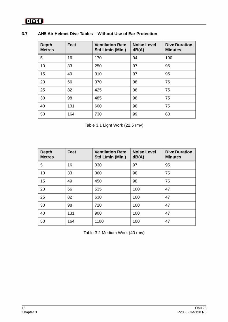
3.7 AH5 Air Helmet Dive Tables – Without Use of Ear Protection
Table 3.1 Light Work (22.5 rmv)
Table 3.2 Medium Work (40 rmv)
Depth Metres
Feet Ventilation RateStd L/min (Min.)
Noise Level dB(A)
Dive Duration Minutes
5 16 170 94 190
10 33 250 97 95
15 49 310 97 95
20 66 370 98 75
25 82 425 98 75
30 98 485 98 75
40 131 600 98 75
50 164 730 99 60
Depth Metres
Feet Ventilation RateStd L/min (Min.)
Noise Level dB(A)
Dive Duration Minutes
5 16 330 97 95
10 33 360 98 75
15 49 450 98 75
20 66 535 100 47
25 82 630 100 47
30 98 720 100 47
40 131 900 100 47
50 164 1100 100 47

OM128 17P2083-OM-128 R5 Chapter 3
Table 3.3 Medium/Heavy Work (62.5 rmv)
Table 3.4 Heavy Work (75 rmv)
Depth Metres
Feet Ventilation RateStd L/min (Min.)
Noise Level dB(A)
Dive Duration Minutes
5 16 380 97 75
10 33 470 99 60
15 49 580 100 47
20 66 660 101 38
25 82 780 101 38
30 98 890 101 38
40 131 1000 101 38
50 164 1320 102 30
Depth Metres
Feet Ventilation RateStd L/min (Min.)
Noise Level dB(A)
Dive Duration Minutes
5 16 400 98 75
10 33 490 99 60
15 49 600 100 47
20 66 720 101 38
25 82 860 101 38
30 98 990 101 38
40 131 1220 102 30
50 164 1500 103 24

18 OM128Chapter 3 P2083-OM-128 R5
(Intentionally Blank)
OM128 19P2083-OM-128 R5 Chapter 4
Chapter 4 - Description
Contents
Page
4.1 Helmet Body ................................................................................................................... 20
4.2 Ports and Frames ........................................................................................................... 21
4.3 Main Air Inlet Adapter ..................................................................................................... 22
4.4 Check Valve .................................................................................................................... 23
4.5 Inlet Valve Assembly ....................................................................................................... 24
4.6 Flow Diffusion ................................................................................................................. 25
4.7 Suit Inflation .................................................................................................................... 26
4.8 Exhaust Valve ................................................................................................................. 27
4.9 Communications ............................................................................................................. 28
4.10 Neck Ring Assembly .......................................................................................................29
4.11 Latch Assembly ............................................................................................................... 30
4.12 Neck Seal ........................................................................................................................ 31
4.13 Harness System .............................................................................................................. 32
4.14 Nose Pad ........................................................................................................................ 33
4.15 Headliner Pad ................................................................................................................. 34
20 OM128Chapter 4 P2083-OM-128 R5
4.1 Helmet BodyThe helmet is constructed from multiple layers of glass fibre matting, resin and lead. Theunit is very carefully constructed to achieve a good balance and strength. Stainless steelHelicoil screw inserts (DD030002) are fitted to receive the retaining screws for the portframes. The upper neck ring (DD030003) is permanently bonded to the helmet.

OM128 21P2083-OM-128 R5 Chapter 4
4.2 Ports and FramesThe two helmet ports are cut from polycarbonate plate. Port thickness for the port(DD030076) is 3/8" and for the top port (DD030073) 1/4". The ports fit into recesses in thehelmet body in which they are sealed on a gasket (DD030072 & 75). Each port is retainedby a metal frame (DD030074 & 77), ten screws (DD030078) securing each frame to thehelmet body.
22 OM128Chapter 4 P2083-OM-128 R5
4.3 Main Air Inlet AdapterThe umbilical airline is connected to the helmet via an adapter (DE079) which is fitted tothe check valve on the air inlet assembly (DD030154).
The external umbilical connection is a 9/16" UNF male, 60° cone seal, to accept the bull-nose fitting and swivel nut most commonly used in the diving industry.
OM128 23P2083-OM-128 R5 Chapter 4
4.4 Check ValveA brass check valve is used to prevent reverse flow of air from the helmet should there beany failure in the main air supply system.
The check valve is a mounted inside the rear face of the inlet valve assembly (DD030154)with the engraved arrowhead pointing upwards into the helmet, and is retained by the airinlet adapter (DE079). Routine maintenance comprises cleaning with warm water anddomestic washing-up liquid, thorough rinsing in fresh water and drying.
24 OM128Chapter 4 P2083-OM-128 R5
4.5 Inlet Valve AssemblyThe inlet valve assembly is the diver’s control for all air input and the connection point forhis umbilical and emergency air. The main air valve knob is positioned at the front of thehelmet and is fully adjustable to give the diver control of the main air flow rate into thehelmet. The stiffness of valve rotation is adjustable as preferred.
The emergency air knob is positioned behind the main air valve knob on the side of theinlet valve assembly. It gives the diver control of the flow rate of emergency air into thehelmet, the stiffness of valve rotation is adjustable as preferred.
The inlet valve body (DD030153) has a 1/4" NPT female inlet for the emergency air supply.The inlet is fitted with an adapter (DD030051) finishing in 9/16” UNF male thread withparallel bore suitable for an ‘O’ ring seal hose tail. The adapter is fitted with a blanking plug(DD030018), sealed by an 'O' ring (DD030053) and retained by a nut (DD030014) forshipping. These parts completely seal the adapter, and prohibit the ingress of dirt to sidevalve.
Remove the nut (DD030014) and blanking plug (DD030018) to connect an emergency airsupply hose fitted with a 9/16” UNF female thread and 'O' ring seal.
Both valve knobs are retained by two pairs of stainless steel socket setscrews(DD030046). One locates in an indent on the spindle and serves to position the knob. Theother locates on the cylindrical surface of the spndle to ensure a rigid connection. Bothouter socket setscrews act as locking screws. Use a hexagonal key 5/64" A/F in the socketsetscrews. For ease of servicing it is important to keep the hexagonal recess in the top ofsocket setscrews filled with candle wax or bees wax, to avoid retention of dirt.
The inlet valve body (DD030154) is located in the helmet by a pin and secured with locknut(DD030048).
OM128 25P2083-OM-128 R5 Chapter 4
4.6 Flow DiffusionThe purpose of the inlet diffusers (DD030140 & 141) is to silence the inlet flow and removeany dust particles that may be in the airline.
This is no substitute for effective filtration at the surface.
The diffusers are flat discs of porous material. They are fitted to the valve body using innerand outer circlips (DD030138 & 139) respectively.
It is recommended that diffusers are washed in non-toxic soap or domestic washing-upliquid. After washing very thoroughly, rinse out the unit in fresh water to remove all traces ofthe washing medium. Do not use any industrial detergents. Blow dry thoroughly with a lowpressure air supply hose before re-use.
26 OM128Chapter 4 P2083-OM-128 R5
4.7 Suit InflationA suit inflation port, ¼” NPT, is provided on the lower surface of the inlet valve body. Thisport is plugged for shipping and will not normally be required where the suit is fitted directlyto the lower ring. When a separate neck seal (DD030091) is fitted, an appropriate suitinflation hose may be connected.
OM128 27P2083-OM-128 R5 Chapter 4
4.8 Exhaust ValveThe exhaust valve body (DD030063) serves as the housing for the components and isflanged and threaded at one end for mounting to the helmet. A lock nut (DD030065)tightened onto the threaded section inside the helmet secures the installation.
The primary valve is of the poppet type (DD030061) and has a groove machined in thepoppet face to receive an 'O' ring (DD030062), ensuring watertight closure.
The poppet valve (DD030061) is held in the closed or seated position by a springarrangement, the tension of which is controlled by the exhaust valve knob (DD030054) atthe outer end of the valve body. The adjustment range is approximately 0.25 to 1.5 psig(0.02 - 0.10 bar) over ambient water pressure.
An override exhaust control is provided by means of a head button (DD030066) attached tothe stem of the poppet valve (DD030061) which protrudes into the helmet. The head button(DD030066) may be utilised to reduce the helmet pressure below a given adjustmentsetting or below the 0.25 psig minimum spring setting.
The secondary exhaust valves (DD030070) are of the mushroom-type and are installed inseries with, and downstream of, the primary exhaust valve outlet. The secondary valvesprevent water from entering the helmet through the open primary valve during the exhaustmode, regardless of diver orientation.
28 OM128Chapter 4 P2083-OM-128 R5
4.9 CommunicationsTwo-way communications are provided by two transceivers (DD030024), housed withinremovable cups (DD030023) which locate in the two ear pods of the helmet body.
The transceivers (DD030024) are water resistant, and have a hole in the rear to enable theunits to pressure compensate. They are wired in parallel with two-core cable to the inboardend of the binding posts (DD030019). The bare ends of the conductors are soldered toeyelets and fixed between two pairs of nuts on connector posts at the back of eachtransceiver (DD030024). The wiring (DD030021) from the left transceiver passes through apre-cut channel in the nose pad (DD030079) adjacent to the shell (DD030001), under theinlet valve duct and then directly to the binding posts (DD030019). The right transceivercable is routed vertically downwards to contact the left-hand-side cable then rearwards tothe binding posts.
At this end, the two eyelets (DD030020) each have connected to them one core from eachcable, and are fixed one to each binding post (DD030019) by a single brass nut.
Also available as an option is a rubber moulded four-pin male connector (DD030027) whichenters the helmet via a feed-through where a 9/16 UNF nut (DD030014) and two 'O' rings(DD030028) keep it secure and watertight, Inside the helmet two of the connector wires arefitted with eyelets (DD030020) and are connected one to each binding post (DD030019).
The connector (DD030027) is wired using the contact pins 1 & 3 (12 and 6 o'clock).Thewires from pins 2 & 4 (3 and 9 o’clock) are cut back inside the helmet.
When the communications connector (27) is not fitted, then the feed-through is fitted with ablanking plug (DD030144), sealed with 'O' ring (DD030101) and secured by a nut(DD030014).
OM128 29P2083-OM-128 R5 Chapter 4
4.10 Neck Ring AssemblyThe neck ring assembly is designed to provide a quick mating or separating of the helmetwhereby a positive mechanical connection and watertight seal are obtained.
The locking arrangement is simple, using the segmented thread system which has beensuccessfully used over many years. A turn of 42 degrees fully engages the rings.
The upper neck ring, the female half of the coupling, is bonded onto the base opening ofthe helmet. There is a large flat sealing surface, protected by a raised outer rim, on thebottom of the upper neck ring.
In the outer rim there is one vertical channel which locates the helmet latch pin(DD030083).There are also two tapped holes to which the countersunk head socketscrews (DD030086) holding the latch body (DD030082) are fitted.
The lower neck ring, the male half of the coupling, carries above its interrupted threads aflat section with an 'O' ring groove and an 'O' ring (DD030081) which seals against thebottom face of the top neck ring. On both front and back of the lower neck ring (4), milledlugs are provided which serve to locate the harness attachment 'D' rings (DD030094).
These lugs are located to accept a length of 3/32" (4 mm) diameter stainless steel cable(DD030092) which is also passed through the centre of two cable sleeves (DD030102) anda sliding stainless steel 'D' ring (DD03094). Each cable end is securely held by crimpedcable stops (DD030093).
The lower neck ring is machined with a lip at the bottom. Over this lip, the AH5 neck seal(DD030091) or neck opening of a dry suit is fitted and clamped on the ribbed surface.
The outer diameter of the lower ring has a machined vertical groove to locate a latch pineccentric head (DD030083). Adjacent to this is a stop pin (DD030087) to prevent thehelmet being over-tightened during dressing.
To facilitate correct engagement of the neck ring threads when dressing, each ring of thehelmet is marked with a coloured alignment dot. When these two dots are aligned, thesegmented threads are free and the rings mated or separated.
30 OM128Chapter 4 P2083-OM-128 R5
4.11 Latch AssemblyThe latch assembly is a positive, double-action system designed to ensure that the helmetlocking seal is not accidentally breached.
1. It is important that the latch lever (DD030085) is in the open position, not flush withthe latch body (DD030082) before attempting to position the helmet on the lowerneck ring.
2. The latch mechanism will close only when the helmet is fully locked to the lower neckring.
3. To protect the latch assembly from damage, the latch lever (DD030085) should be inthe closed position at all times other than when mating the helmet with the lower neckring.
After mating of the helmet rings, rotate the helmet clockwise (viewed from above) aboutone-eighth of turn (actually 42 degrees), then close the latch lever (DD030085). As itcloses, the latch bar (DD030083) will engage in the slot adjacent to the stop pin(DD030087) on the lower neck ring.
When detaching the helmet from the lower neck ring, it is first necessary to push the latchlever (DD030085) upwards to a stop before opening it outwards.
The lever (DD030085) is locked into the latch bar (DD030083) by two socket setscrews(DD030046), hexagonal key size 5/64" A/F (2 mm), that bear on a flat on the lever stud(DD030085). For ease of servicing it is important to keep the hexagonal recess in the top ofsocket setscrews filled with candle wax or bees wax, to avoid retention of dirt.
The latch body is fixed to the upper neck ring by two countersunk head socket screws(DD030086). A hexagonal key size 5/32" A/F is required for fitting.
OM128 31P2083-OM-128 R5 Chapter 4
4.12 Neck SealThe conical shaped neck seal (DD030091) is fabricated from double nylon lined foamedneoprene. Seams are joined with neoprene cement then stitched for added strength. Thelarger opening of the neck seal is fitted over the wide ribbed band in the lower neck ringwhere it is clamped in place with a single clamp band assembly (DD030088). The doublethickness neoprene bead provides a positive stop for the clamping.
If required, the neck seal can be glued and stitched directly to some dry diving suits.
32 OM128Chapter 4 P2083-OM-128 R5
4.13 Harness SystemThe harness (DD030106) is the means by which the helmet is held in position for divercomfort and versatility. The only parts of the harness system attached to the helmet lowerneck ring are two sliding 'D' rings (DD030094), each retained by a short length of stainlesssteel cable (DD030092).
The harness (DD030106) completes the system. It comprises:
1. A waist belt, tightened by stainless steel double 'D' rings, to which the various partsare attached.
2. Two leg straps, each fixed to the waist belt at one point only on the outside of eachleg.To dress, each strap is fed across the back of its respective leg, under the crutch,and continues around the same leg over the front, returning to the starting point. Hereit is attached to and adjusted to length by an adjustable 'D' which is itself permanentlysecured to the waist belt.
3. Two locking straps, one front and one back, are fixed to the waist belt by webbingloops, and are free to self centre on the waist belt. Each has an adjustable snapwhich locates in the 'D' ring of the helmet lower neck ring.
4. One large safety 'D' ring which is permanently fixed to the waist belt on the diver'sright hand side. This is for umbilical tie-off or tools.
OM128 33P2083-OM-128 R5 Chapter 4
4.14 Nose PadA pad (DD030079) is located along the lower rim of the helmet below the front port(DD030076). It is made with multiple layers of foam neoprene, with wedges cut out of thefirst layer, to take up the angle of the helmet surface, and through which the transceiverharness wire (DD030021) is run. This pad may be repositioned and reshaped for diverpreference.
34 OM128Chapter 4 P2083-OM-128 R5
4.15 Headliner PadA rectangular shaped pad (DD030080) of lined neoprene is fixed to the top inner surface ofthe helmet, to provide a cushioning effect when the helmet is worn out of the water.Additional padding can be glued around the inside of the helmet to suit divers' individualpreferences. If this is done, allow several hours for the glue to cure and for harmful fumesto disperse.
OM128 35P2083-OM-128 R5 Chapter 5
Chapter 5 - Operating Instructions
Contents
Page
5.1 Operating Instructions ..................................................................................................... 36
5.2 Surface Air Supply Requirements ................................................................................... 37
5.3 Pre-dive Checks .............................................................................................................. 38
5.4 Helmet Dressing Procedure ............................................................................................ 40
5.5 After-Dive Procedure ......................................................................................................42
5.6 Emergency Procedures .................................................................................................. 43
36 OM128Chapter 5 P2083-OM-128 R5
5.1 Operating InstructionsThe advice in this section is for guidance. Different diving situations will affect in detail theway in which the Divex AH5 is used. Always have a stand-by diver and always connect anindependent diver-carried emergency air supply system. It is recommended that the diverfamiliarise himself with the AH5 in quiet water before going on his first job with the helmet.
OM128 37P2083-OM-128 R5 Chapter 5
5.2 Surface Air Supply RequirementsThe AH5 must be used with surface supplied air from an air compressor, regulated bank ofair cylinders or both. The flow rate must be high enough to ensure sufficient ventilation atthe working depth to prevent the carbon dioxide level in the helmet from rising above safelimits. A safe rate will be between approximately 3 and 6 ambient cubic feet per minute(acfm), depending on the workload and breathing levels.
The pressure must be sufficient to overcome the water pressure at the diver's depth, pluspressure loss in the air supply system. As a rule of thumb, allow 60 psi (4.2 bar) overbottom pressure for depths up to 120 feet (36.6 metres). For depths greater than 120 feetadd 100 psi (6.9 bar) over bottom pressure.
38 OM128Chapter 5 P2083-OM-128 R5
5.3 Pre-dive ChecksInspect the helmet and harness (DD030106) for general condition and functions. Checkthat all fittings are securely attached to the helmet, that the valve controls operate smoothlyand that the silencer housing (DD030037) is set to direct air in the diver's preferreddirection.
5.3.1 Lower Neck Ring CheckCheck that the neck seal (DD030091) or suit yoke is positioned correctly on the lower neckring. When a neck seal is fitted, the bead is positioned so that it folds back over the entireclamp band (DD030088). Check that the clamp band is securely tightened. Foamneoprene does compress over time, requiring the clamp band to be re-tightened.
Check that the 'O' ring (DD030081) is clean and free of embedded particles, that the slidecable (DD030092) is in sound condition with the cable crimps (DD030093) firmly fixed andthe cable sleeves (DD0300102) in tact.
5.3.2 Exhaust Valve CheckCheck that the exhaust knob (DD030054) turns freely through the full range of adjustment,and that the head button (DD030066) also operates smoothly throughout the adjustmentrange. To ensure correct operation, these checks should be carried out again after thehelmet is put on the diver.
5.3.3 Location Latch CheckPut latch lever (DD030085) in the closed/locked position. Then check that it can be movedsmoothly upwards against the pressure of the latch spring (DD030084). While the lever(DD030085) is still held upward, check that it can be smoothly swung open to the unlockedposition. If the latch mechanism is sticky then clean the assembly and apply a smallamount of lubricant or WD40 spray. Take care not to get any spray on the helmet faceports.
5.3.4 Check Valve TestTest that the check valve is operational.
Method:Open the helmet main air valve. Try to inhale through the main air inlet adapter (DE078).When the check valve is functioning correctly there will be no inhalation. If in doubt thencarry out the following procedure:
1. Purge air supply hose to ensure system cleanliness.
2. Connect air supply hose to main air inlet adapter (DE079), and apply 100-150 psig airpressure to helmet.
3. Open helmet main air supply valve, verify air flow in helmet, then close this valve.
4. Purge air from the supply hose and then remove from helmet.
WARNING
This is a critical piece of safety equipment, no diving should be undertaken if it is faulty.
OM128 39P2083-OM-128 R5 Chapter 5
5. Submerge the air inlet adapter (DE079) in a small container of water and look forbubbles. If bubbles escape then the check valve is not functioning correctly. Formaintenance and repair to check valve refer to Section 5.4.
6. Open helmet main air supply valve and verify venting of air trapped downstream ofthe check valve.
5.3.5 Communications CheckThe best method is to connect the helmet to a surface diver phone and check function withan assistant.
Alternatively, without assistance, connect up with the surface phone (DD030024) one at atime. Each should be heard from the surface phone. To check communications in thereverse direction, talk into the surface speaker whilst feeling within finger tip each helmettransceiver (DD030024). Vibration should be felt in the transceiver. Another quick methodis to induce feedback between the helmet and surface phone, which will confirm the correctfunction of at least one of the two helmet transceivers.
5.3.6 Breathing System CheckBlow through the umbilical to clear out any dirt, and then connect the air line to main airinlet adapter (DE079).
Do up hand-tight plus a quarter turn. Do not tighten the 9/16" nut with stilsons!
Turn the emergency air valve off.
Open the main air valve and check that the flow level is regulated by adjustment of thisvalve and that there is no flow when the valve is turned off.
5.3.7 Emergency Air Supply CheckCheck the pressure in the diver-carried emergency air supply. Always use a full cylinder ofadequate capacity for the planned dive. Remember that the diver will need between 3 and6 acfm (ambient cubic feet per minute).
5.3.8 Front Port Seal CheckAfter delivery and/or storage and prior to any use the front port screws are to be checkedfor tightness using a torque spanner set at 12 in/lbs.
WARNING
Always use the correct size spanner and do not over tighten.
40 OM128Chapter 5 P2083-OM-128 R5
5.4 Helmet Dressing ProcedureEvery assistance should be given to the diver whilst he is being dressed and as he movesaround after dressing. He will expend a lot of energy moving around with all his equipmentat the surface.
The precise order of dressing and after-dive procedure will be dependent on the method ofuse of the helmet, whether it is to be worn with its own independent neck seal (DD030091),or with the lower neck ring attached directly to a dry suit.
When used with independent neck seal:
1. Fit the diver's AH5 harness (DD030106). Begin by fitting the waist band with thedouble 'D' buckles on the diver's left hand side, the long leg straps running verticallydown the diver's legs and the parachute legging adjusters angled down from thewaist belt. From the outside of each leg take the leg strap and feed it across the backof the same leg, under the crutch and continue around the same leg over the front,returning to the starting point. Fit to the adjustable 'D' buckle on the waist belt. Leavehanging down the two jocking straps which are suspended from the waist belt.
2. Pull the lower neck ring assembly over the diver's head ensuring that the red locationdot is on the diver's left side.
3. Adjust the neck seal (DD030091) to suit personal preference. The neck seal can beworn in two ways. If the seal opening is a little too large or loose, the edge can beturned in (similar to the way in which the wrist cuffs on deep-sea dress are turned in)and pushed up on the neck to give an adequate seal. When worn this way, any watercollecting in the resulting pocket of the neck seal (DD030091) around the neck willhave to be purged through the exhaust valve. Alternatively, with the edge of the neckseal pointing downwards, any excess air will blow out of the bottom of the seal, andmoisture or water in the helmet will also be expelled.
4. Fasten both harness straps' adjustable snaps to the 'D' rings on the lower neckring.Tension the rear harness straps at this time with the diver keeping hold of thelower neck ring, to keep its position horizontal.
5. Fit the emergency air system - comprising cylinder, first stage scuba regulator,pressure gauge and whip, safety valve and supply whip, all connected to a backpackor safety harness.
6. Fit weight belt, if weights are not incorporated into a safety harness system.
7. Ensure that the umbilical airline and telephone cable have been connected to thehelmet. Turn on the AH5 main air supply valve to give a good flow to the diver. Thenfit the helmet to the diver as follows:
Open the latch lever (DD030085) on the helmet before the helmet is placed over thediver's head. To assist the attendant fitting the helmet, the diver should lift the lowerneck ring at the front bringing it to the horizontal position. When the helmet is over thediver's head, position the two red location marks in line, then seat the helmet on tothe lower neck ring. The location marks are near the diver's left shoulder. Turn thehelmet clockwise until the latch bar (DD030083) lines up with its recess in the lowerneck ring.The stop pin (DD030087) in the lower neck ring will prevent the helmetbeing turned too far. Then close the latch lever (DD030085) causing the latch bar
OM128 41P2083-OM-128 R5 Chapter 5
(DD030083) to lower into a recess in the lower neck ring and lock in the closedposition.
8. The diver should now check that the air supply is on, that the main air valve isfunctioning and that a high flow of air is delivered when the valve is fully open.
9. Operate the head button (DD030066). The diver should notice an immediate buttemporary reduction in internal air pressure.
10. Carry out a check of the communications in both directions and adjust the surfacephone volume controls. Set the diver's listening level a little high so that the diver willstill hear clearly over the additional bubble noise on entering the water.
11. Connect the emergency air whip to the adapter (DD030051) on the inlet valveassembly. Ensure that the emergency valve is in the off position. Then turn on theemergency air supply at the cylinder valve, to give air pressure up to the emergencyair valve and check the emergency air cylinder pressure. The diver should now checkthe emergency air supply by first turning the helmet’s main air valve off, and thenopening the emergency air supply valve, when a smooth flow of air should resume.Then turn off the emergency air valve and re-establish main-air supply.
12. Connect the umbilical safety line snap hook to the diver's harness in such a way thatno load put on the umbilical or diver will be taken up by the helmet's inlet adapter(DE079) and umbilical connections.
13. The diver is now dressed in the helmet. Just before moving off and entering thewater, final jocking adjustments should be made. The tender should pull down firmlyon the front strap. The diver will usually be more comfortable if this is done beforeentering the water.
When used fitted to a dry suit:
Dressing procedure is much quicker when the helmet's lower neck ring is leftpermanently attached to a zip entry dry suit.
Dressing procedure is the same as when used with an independent neck seal(DD030091), except that the lower neck ring is in place whenever the suit is on.
42 OM128Chapter 5 P2083-OM-128 R5
5.5 After-Dive ProcedureThe surface tender should give the diver every assistance when he returns from the water,including help in negotiating ladders.
After completion of the dive, if weights are carried in a separate belt, remove the weightbelt, then release the helmet. First, disengage the latch bar (DD030083) by pushing thelatch lever (DD030085) upwards, and then swinging it outwards. Next, turn the helmet anti-clockwise (viewed from above) until the location dots on each ring line up over the diver'sleft shoulder. The helmet should then be carefully removed from the diver's head.
Turn off the main air supply at source and the valve on the diver-carried emergency aircylinder. Open both the helmet's main air and emergency air valves to bleed residualpressure in the two hoses. Disconnect the emergency air whip, communications cable andmain air hose from the helmet. If the helmet is being used with a neck seal (DD030091)then disconnect the harness (DD030106) from the sliding 'D' rings (DD030094) and allowthe diver remove the lower neck ring from his head.
Wherever practical at the worksite, keep the helmet and lower neck ring as an assembledunit, with the latch lever (DD030085) closed.
Before long term storage, the harness (DD030106) and lower neck ring assembly shouldbe rinsed in warm fresh water, wiped clean and dried. Clean the outside of the helmet infresh water, particularly the exhaust valve assembly, and wipe with a damp cloth the insideof the lower neck ring sealing surfaces, and the lower neck ring 'O' ring. Note any itemsrequiring maintenance. The outer surface may be polished with a household furniturepolish.
OM128 43P2083-OM-128 R5 Chapter 5
5.6 Emergency ProceduresPractice emergency procedures before using the equipment for the first time. Always planfor possible emergencies.
5.6.1 FloodingProvided sufficient air flow and pressure are maintained, water should not enter the helmet.Partial flooding of the helmet can be quickly cleared through the exhaust valve by tilting thehelmet until the exhaust valve is at the lowest point.
The water will be cleared more quickly if the air flow into the helmet is increased and theexhaust valve head button (DD030066) activated.
5.6.2 Main Air Supply FailureNever use the AH5 without a diver-carried emergency air supply of adequate capacity.Prior to diving, the emergency supply system should be checked. The emergency aircylinder valve should be left in the on position and the emergency air whip pressurisedthrough to the helmet emergency air inlet valve which should be in the off position.
If the main air supply fails, turn on the emergency air inlet valve knob and set it to give theminimum safe flow of air and reduce diver exertion to the minimum so as to conserve air.Advise the surface immediately of the situation and plan to terminate the dive. Startascending to the surface or the first decompression stop.
The pneumofathometer hose can be used as an additional source of emergency air byinsertion under the neck seal (DD030091) or under a suit cuff as appropriate then requestcontinuous supply.
5.6.3 Suit Blow UpWhen the AH5 is locked directly into the dry suit then the possibility of blow-up exists.
The diver needs to guard against:
1. Rapid increase in buoyancy caused by the diver going from head-up to feet-upposition, since the exhaust valve will then be positioned below the suit so that thewhole suit will inflate before the exhaust valve will automatically vent through overpressure.
2. Unnoticed gradual increase of suit inflation caused by clogging of the exhaust valve.
The potential for buoyancy increase is governed by the looseness and expansioncapabilities of the suit. Control the potential expansion of the suit leggings with laced boots,leg straps or automatic over-pressure relief valves. Use weighted boots and/or leg weightsto encourage stability with a feet down attitude.
When diving in particularly muddy or silty waters operate the head button (DD030066) atregular intervals to prevent clogging of the exhaust valve.
At the first sign of over-inflation, operate the head button (DD030066) and assume a headup position to vent down suit pressure. Should a blow-up occur then close the main air inletvalve, use the head button (DD030066), and vent from a suit cuff held above the head.
5.6.4 Rapid Loss of BuoyancyShould this happen when the AH5 is locked into a dry suit then completely open the air inletvalve and adjust helmet exhaust valve to give maximum over pressure.
44 OM128Chapter 5 P2083-OM-128 R5
The pneumofathometer hose can also be used as an emergency source of air by insertionunder the neck seal (DD030091) or under a suit cuff as appropriate then requestcontinuous supply.
OM128 45P2083-OM-128 R5 Chapter 6
Chapter 6 - Repair and Maintenance
Contents
Page
6.1 Repair and Maintenance ................................................................................................. 46
6.2 Daily Maintenance .......................................................................................................... 47
6.3 Three Monthly Maintenance ........................................................................................... 48
6.4 Ports ................................................................................................................................ 49
6.5 Check Valve and Main Inlet Adapter ............................................................................... 50
6.6 Air Inlet Valve Assembly ................................................................................................. 51
6.7 Exhaust Valve ................................................................................................................. 53
6.8 Communications ............................................................................................................. 55
6.9 Latch Assembly ............................................................................................................... 57
6.10 Lower Neck Ring Assembly ............................................................................................ 58
6.11 Lower Neck Ring Sliding “D” Ring Assembly .................................................................. 60
6.12 Neck Seal ........................................................................................................................ 61
6.13 Replacement Nose Pad, Liner Pad & Velcro Fasteners ................................................. 62
6.14 Harness ........................................................................................................................... 63
6.15 Helmet Shell - Glass Fibre .............................................................................................. 64
6.16 Socket Set Screws........................................................................................................... 65
46 OM128Chapter 6 P2083-OM-128 R5
6.1 Repair and MaintenanceMaintenance schedules will differ according to the type of diving work being undertaken.We offer the following guidance as to what may be a suitable maintenance procedure.
For details of how to maintain each assembly, refer to the relevant Section(s) withinsection 6.4 to section 6.16.
It is imperative that the helmet in a good operational condition.
Always use the correct tools.
Spanners of the wrong size, adjustable spanners, Mole wrenches, Stilsons and similarinappropriate tools can cause serious problems. Because they are ill-fitting they will round-off nuts and if they offer excessive leverage, they can overstress threads. Using hexagonalkeys of the wrong size will quickly deform recesses in socket screws making themextremely difficult to extract.

OM128 47P2083-OM-128 R5 Chapter 6
6.2 Daily Maintenance1. Inspect the helmet inside and out for any obvious damage.
2. Inspect the neck seal (DD030091) for damage and check that it is securely clampedto the lower neck ring.
3. Check all moving parts for smooth function - the main air inlet and emergency valves,the exhaust valve knob (DD030054) and head button (DD030066) and the latch lever(DD030085).
4. Check the check valve by blowing in one direction, and then trying to suck back.
5. Check that both transceivers (DD030024) are securely fixed inside the helmet andthat, if fitted, the pins of the communications connector (DD030027) are straight.
6. Visually check the lower neck ring 'O' ring (DD030081).
48 OM128Chapter 6 P2083-OM-128 R5
6.3 Three Monthly Maintenance1. Remove and clean air inlet adapter (DE079) and check valve components. Replace
'O' rings RN4016-7 & RN804-7. Re-assemble and re-test.
2. Dismantle the exhaust valve and clean all components. Replace the mushroomexhaust valves (DD030070) and the poppet valve 'O' ring (DD030062). Re-assembleand test. Refill socket setscrew recesses with candle or bees wax.
3. Replace 'O' ring (DD030081) in lower neck ring.
4. Dismantle inlet valve assembly. Clean valve body (DD030154), and inspect the mainair inlet valve spindle/seat assembly (DD030176) and emergency air inlet valvespindle/seat assembly (DD030044). Lubricate with molybdenum disulphide grease.Re-assemble and test. Refill socket screw recesses with candle or bees wax.
5. Clean and test inlet diffusers (DD030140 & 141) for obstruction. If cleaning is notcompletely successful, replacement is necessary.
6. Check that both transceivers (DD030024) transmit and receive clearly and that theunits are securely fixed in the helmet. If a communications connector (DD030027) isfitted, check that its pins are straight, and the cable connections to the binding posts(DD030019) are sound.
7. Remove the latch lever (DD030085), latch bar (DD030083) and spring (DD030084)from the latch body (DD030082). Clean all latch assembly parts. Apply a lightsmearing of silicone grease to the moving parts, replace and test for positive lockingaction and a smooth movement. Refill the latch bar (DD030083) socket setscrewrecess with candle or bees wax.
8. Check neck seal (DD030091) for condition and repair/replace as necessary.
9. Check, repair or replace as necessary the harness (DD030106) webbing, stitchingand buckles and the sliding 'D' ring (DD030094) assembly on the lower neck ring.
10. Inspect the helmet generally for any other damage and repair.
11. Finally connect communications line, main-air and emergency air supplies and testall functions in the dry.
OM128 49P2083-OM-128 R5 Chapter 6
6.4 PortsThe polycarbonate material used in the two ports is very strong. However, care should betaken not to use certain solvents which may attack the material. Use only mild detergentsor organic soap to clean the ports. Do not contact with silicone spray or any other aerosols,as this will damage the polycarbonate.
6.4.1 Scratch Removal and PolishingScratches are normally removed from polycarbonate ports (DD030073 & 76) using acrylicpolishing compounds. However, satisfactory results may be obtained using any fine gradepolishing compound, toothpaste or jewellers rouge. Small scratches are generally notnoticeable when underwater.
6.4.2 Port ReplacementRemove all screws 8-32 UNC (DD030078) from the port frame (DD030074 or 77). The port(DD030073 or 76) is easily removed by lightly tapping from inside the helmet. If a newgasket is to be used then remove the gasket strip (DD030072 or 75) by simply lifting oneedge and pulling away. Using a clean rag, wipe away any dirt or grease to ensure a cleansurface for the new gasket.
Use a pre-cut replacement gasket (DD030072 or 75). Remove a small amount of thebacking strip. Carefully lay the gasket starting from the midpoint of a straight edge of therecess, ensuring that it is maintained flat whilst it is eased into each corner. After laying thegasket all round, overlap the free ends.
Remove protective paper from the replacement port (DD030073 or 76) and install it. Eitherside can be used. Then infill any gap between the port, the gasket and the helmet shell withany non-setting mastic to eliminate any gap that can collect dirt. Install the port frame(DD030074 or 77) initially by screwing all of the screws (DD030078) into each stainlesssteel insert (DD030002) until they just begin to bind. Then proceed with care to tightendiagonally opposing screws half a turn at a time, until all screws are tightened down. Portscrews are to be checked for tightness using a torque spanner set at 12 in/lbs. Do not overtighten as this may strip the screw insert (DD030002).
If no replacement gasket is available the existing gasket may be re-usable, provided its topsealing surface is kept clean. If the gasket is not sealing effectively, then a temporary sealcan be made by applying soft mastic to the top of the existing gasket strip and thenreplacing the port, frame and screws.
50 OM128Chapter 6 P2083-OM-128 R5
6.5 Check Valve and Main Inlet Adapter
6.5.1 Check Valve RemovalUsing a 24mm spanner, loosen the check valve from the inlet valve body assembly(DD030154). Remove the ‘O’ ring (RN4016-7) and check for damage or deformation.Remove the air inlet adapter (DE079) from the check valve body. Visually inspect thecheck valve for body or thread damage. If signs of damage are apparent, replace thecomplete check valve.
6.5.2 Check Valve TestPerform preliminary test of check valve by placing the valve to mouth and verifying ease offlow in direction of arrow on the valve body. Verify that reverse flow is not possible byblowing air through in the reverse direction. Then try to suck air in the reverse direction. Ifreverse flow is possible the check valve requires servicing using spares kit DD030220which includes all internal sealing components.
6.5.3 AssemblyRefit inlet adapter (DE079) to Non Return Valve Adaptor (DD030170) Smear 'O' ring(RN4016-7) with a light film of silicone grease and fit in groove on adaptor.
Refit check valve components to helmet inlet valve assembly.
To confirm the check valve has been serviced and refitted correctly, refer to pre-divechecks.
OM128 51P2083-OM-128 R5 Chapter 6
6.6 Air Inlet Valve Assembly
6.6.1 Main Air Valve Bonnet Sub-AssemblyFirstly, the valve seals must be checked for air tightness and correct seating.
Remove wax from the two socket setscrew recesses on the valve knob (DD030045). Usinga 5/64" A/F hexagonal key, remove the two pairs of socket setscrews (DD030046) securingvalve knob to spindle (DD030044).
Connect emergency air supply to the helmet. Test the valve by turning on the air supply atsource and keeping the helmet valve turned off. Use soapy water on the outside of thevalve bonnet to check for leakage from the bonded seal (DD401129) and the stem seal(DD030043) in the bonnet assembly.
To test the emergency air valve seat, immerse a small flat-sided object in soapy water andplace over the inboard end of the valve body duct and repeat the above test. If bubblesappear, then the valve spindle/seat (DD030174) must be inspected. Remove the seat andinspect it for conditiOn and wear. If the seat is nicked or grooved the spindle/seat assemblyshould be replaced. If the stem seal (DD030043) leaks, tighten bonnet nut (DD030166)and re-check for leakage. If unsatisfactory after tightening, the stem seal (DD030043) mustbe replaced. To replace either the stem seal or spindle/seat assembly, use a 21 mmspanner on the gland nut (DD030166), to remove it from the bonnet (DD030164). Thenremove the spindle (DD030174) by unscrewing from bonnet then remove the brass bush(DD030104) and stem seal (DD030043) from the bonnet (DD030164). To remove thebonnet assembly (DD030163) and bonded seal (DD401129) from the side valve body(DD030154), use a 1” A/F spanner.
When re-assembling the bonnet, coat the spindle thread (DD030174), bush (DD030104),seal (DD030043) and gland nut (DD030166) with a light film of molybdenum disulphide(MoS2) grease. Insert the spindle (DD030174) into the bonnet (DD030164) and screw inuntil it bottoms in the bonnet. Then install a seal (DD030043), brass bush (DD030104) withconcave side towards the seal (DD030043), and gland nut (DD030166). Fit the bondedseal (DD401129) on the bonnet (DD030164) and install it into the inlet valve body(DD030153).Tighten the gland nut (DD030166) to the point where the spindle (DD030174)cannot be rotated by hand. Fit the valve knob upside down and fasten with socketsetscrews using a 5/64" AF Allen key. Repeat the bonnet assembly leak test and adjustgland nut if required ensuring that the valve is operable. Re-fit the valve knob (DD030045)in the correct position using a 5/64" A/F hexagonal key.
6.6.2 Emergency Air Inlet Valve Bonnet Sub-AssemblyFirstly, the valve seals must be checked for air tightness and correct seating.
Remove wax from the two socket setscrew recesses on the valve knob (DD030045). Usinga 5/64" A/F hexagonal key, remove the two pairs of socket setscrews (DD030046) securingvalve knob to spindle (DD030044).
Connect emergency air supply to the helmet. Test the valve by turning on the air supply atsource and keeping the helmet valve turned off. Use soapy water on the outside of thevalve bonnet to check for leakage from the bonded seal (DD401129) and the stem seal(DD030043) in the bonnet assembly.
To test the emergency air valve seat, immerse a small flat-sided object in soapy water andplace over the inboard end of the valve body duct and repeat the above test. If bubblesappear, then the valve spindle/seat (DD030044) must be inspected. Remove the seat and
52 OM128Chapter 6 P2083-OM-128 R5
inspect it for condition and wear. If the seat is nicked or grooved the spindle/seat assemblyshould be replaced. If the stem seal (DD030043) leaks, tighten bonnet nut (DD030166)and re-check for leakage. If unsatisfactory after tightening, the stem seal (DD030043) mustbe replaced. To replace either the stem seal or spindle/seat assembly, use a 21 mmspanner on the gland nut (DD030166), to remove it from the bonnet (DD030165). Thenremove the spindle (DD030044) by unscrewing from bonnet then remove the brass bush(DD030104) and stem seal (DD030043) from the bonnet (DD030165). To remove thebonnet assembly (DD030167) and bonded seal (DD401129) from the side valve body(DD030154), use a 1” A/F spanner.
When re-assembling the bonnet, coat the spindle thread (DD030044), bush (DD030104),seal (DD030043) and gland nut (DD030166) with a light film of molybdenum disulphide(MoS2) grease. Insert the spindle (DD030044) into the bonnet (DD030165) and screw inuntil it bottoms in the bonnet. Then install a seal (DD030043), brass bush (DD030104) withconcave side towards the seal (DD030043), and gland nut (DD030166). Fit the bondedseal (DD401129) on the bonnet (DD030165) and install it into the inlet valve body(DD030153). Tighten the gland nut (DD030166) to the point where the spindle (DD030044)cannot be rotated by hand. Fit the valve knob upside down and fasten with socketsetscrews using a 5/64" AF Allen key. Repeat the bonnet assembly leak test and adjustgland nut if required ensuring that the valve is operable. Re-fit the valve knob (DD030045)in the correct position using a 5/64" A/F hexagonal key.
6.6.3 CleaningConnect a low pressure air supply to the main inlet and blow any particles from the inletvalve body. A small brush or cotton cloth may prove helpful in removing particles from thisarea. Do not use a sharp object.
Clean the complete bonnet assemblies, or all its parts if previously dismantled formaintenance, plus the knobs (DD030045) and socket setscrews (DD030046) in warmsoapy water. Rinse in fresh water and wipe dry.
6.6.4 Inlet Valve Body RemovalShould it ever be necessary to remove the inlet valve body assembly (DD030154) from theshell (DD030001), proceed as follows:
Remove the air deflector from the body duct inside the helmet. This is a push fit. Using apurpose-made spanner, slacken and remove lock nut (DD030048). Pull inlet valve bodyassembly (DD030154) away from the shell taking care not to damage the shell wheresealant has formed a bond and where the location pin is fitted.
6.6.5 Inlet Valve Body ReplacementUse Dow Corning silicone rubber compound sealant type 732 RTV or equivalent. Spreadgenerously on the flange of the inlet valve body (DD030153). Leave to stiffen and is dry totouch before fitting to the helmet. Ensure that the locating pin on the inlet valve body(DD030153) is in the locating hole of the helmet. Wipe all sealant off the valve bodythreads. Refit lock nut (DD030048) from inside the helmet. Wipe away excessive sealantafter tightening of the lock nut. Connect air supply and verify air flow.
OM128 53P2083-OM-128 R5 Chapter 6
6.7 Exhaust Valve
6.7.1 DismantlingRemove wax from socket setscrew recesses. Unscrew the two screws (DD030071) andremove grating (DD030068). Using a hexagonal key size 5/64" A/F, remove socketsetscrews (DD030067) to allow disengagement of secondary body. Remove secondarybody (DD030069) and remove the mushroom valve (DD030070). Remove inner mushroomvalve from the exhaust body (DD030063). To remove the pressure adjustment assembly,withdraw socket setscrews (DD030067) then remove outer assembly giving access to theprimary spring (DD030060) and poppet valve (DD030061). Remove poppet valve byunscrewing the head button (DD030066) and remove 'O' ring (DD030062). Rotate theexhaust knob (DD030054) fully clockwise to expose the external circlip (DD030059).Remove the circlip, using appropriate pliers. Remove the knob (DD030054) by unscrewingfrom the cover nut (DD030055). Remove the internal circlip (DD030058), spring retainer(DD030109) and the secondary spring (DD030056) by inserting internal circlip pliers in theexhaust knob (DD030054) bore and compressing the circlip (DD030058) to remove it. Thespring (DD030056) and spring retainer (DD030109) are then free to be withdrawn.
6.7.2 CleaningAll metal parts can be soaked in white vinegar (acetic acid) for 15-30 minutes. Rinse allsoaked parts in fresh water. Use a dampened cloth to wipe clean all parts, including theinside of the exhaust valve body (DD030063), with particular attention to valve seatingsurfaces.
6.7.3 Assembly
NoteDuring routine maintenance it is advisable to replace the two rubber exhaust valves(DD030070) and poppet valve 'O' ring (DD030062). Apply a light film of silicone spray to allmetal parts. Install the secondary spring (DD030056) (short spring) followed by the springretainer (DD030109) (large diameter end against the spring) in the exhaust knob(DD03054) bore. Using circlip pliers install the internal circlip (DD030058) in the grooveprovided within the knob (54) bore. Verify that the circlip (DD030058) is well seated in thegroove and that the spring (DD030056) and spring retainer (DD030109) move freely whendepressed. Re-thread cover nut (DD030055) onto the exhaust knob (DD03054). Usingcirclip pliers install the external circlip (DD030059) in the machined groove located at theend of the threaded section of the exhaust knob (DD030054). Verify proper installation.
Apply a light film of silicone grease to the sealing surface only of the two rubber exhaustvalves (DD030070). Install both valves in their respective positions by placing the valvetabs through the location holes of the valve bodies, and pulling the free end of the tabs withpliers until the recess in the valve tab locates in the housing body, with the valve firmly heldin place.
Install secondary body (DD030069) and secure by screwing in the two socket setscrews(DD030067), using a hexagonal key 5/64" A/F.
Fix in position the grating (DD030068) by using the two screws (DD030071). Apply a lightfilm of silicone grease to 'O' ring (DD030062) and install on the poppet valve (DD030061).Install a poppet valve (DD030061) into exhaust body (DD030063). Hold firmly the poppetvalve and screw on head button (DD030066) from inside the helmet. Install the primaryspring (DD030060) over the poppet valve stem plunger inside the valve body.
54 OM128Chapter 6 P2083-OM-128 R5
Install the exhaust knob/cover nut assembly ensuring the primary spring (DD030060)enters the knob bore, secure the assembly with the two socket setscrews (DD030067),using a hexagonal key 5/64" A/F.
Refill the socket setscrew recesses with candle wax or bees wax.
Check that the exhaust knob (DD030054) turns smoothly throughout the full range ofadjustment, and that the head button (DD030066) also operates smoothly throughout theadjustment range.
Then check that the poppet valve (DD030061) is seating properly. Do this by screwing theexhaust knob (DD030054) fully in and then with the fingers gently try to pull the headbutton further out into the helmet. There will be no movement inwards if the poppet valve(DD030061) is assembled correctly, with the primary spring (DD030060) holding thepoppet valve against its seat.
Finally, to verify the system has been assembled correctly, connect the helmet to an airsupply, pressurise the system and fit with the lower neck ring assembly to the persontesting the unit. The helmet must be sealed, either by attaching directly to a dry suit or witha neck seal (DD030091).
OM128 55P2083-OM-128 R5 Chapter 6
6.8 Communications
6.8.1 Transceiver ReplacementTo remove a transceiver (DD030024) from its position in the helmet ear pod, carefullyseparate the Velcro fastenings (DD030025) at the back of the transceiver cup (DD030023).
Gently remove the cup (DD030023) from the transceiver (DD030024) and expose the twotransceiver connector posts. Remove the top nut from each connector post to disconnectthe transceiver (DD030024) from the harness wires (DD030021), and then refit the harnesswires to the connector posts of the replacement transceiver (DD030024), one wire to eachpost, sandwiched between the two nuts. Take care not to block the pressure equalisationhole at the back of the transceiver, and ensure that no stray strand of wire bridges the gapbetween the two connector posts. Refit the transceiver (DD030024) in the cup (DD030023)and the cup into the helmet ear pod, using the Velcro fasteners (DD030025).
The wire harness (DD030021) connects the two transceivers in parallel to the inboard endof the two binding posts (DD030019). Each binding post is connected to one connectorpost of each transceiver.
The wiring (DD030021) form the left-hand transceiver (DD030024) passes underneath thenose pad (DD030079) in a pre-cut channel, and then passes under the inlet valveassembly and then on to the binding posts (DD030019). The right-hand transceiver wireruns vertically down to the left-hand cable then follows this line to the binding posts. Thetwo transceivers are connected in parallel and joined by eyelets (DD030020) which areattached to the binding posts by brass nuts.
After re-assembly, test for correct function.
6.8.2 Connector ReplacementThe rubber moulded connector is an optional item.
From inside the helmet undo the two retaining nuts securing the connector eyelets(DD030020) to the binding posts (DD030019). Using a 21mm spanner unscrew the glandnut (DD030166).
Pull out carefully the connector (DD030027). When replacing a connector it is advisable torenew the two 'O' rings (DD030028).
For tidiness in the helmet it is preferable that only two of the connector wires are attachedto the terminal posts, and that the other two are trimmed back. This trimming is best donebefore fitting the connector to the helmet. Establish by testing with your umbilical which ofthe two connector wires is to be used and then trim back the other two. As supplied, thehelmet connector is wired using the contact pins 1 & 3 (12 and 6 o'clock).
To install a replacement connector (DD030027) first fit gland nut (DD030166) and 'O' rings(DD030028) to the connector before threading connector into helmet.
Ensure the connector has protruded sufficiently into the helmet to enable the eyelet(DD030020) to be fastened to the two binding posts (DD030019) and then tighten thegland nut (DD030166) using an 21 mm spanner.
Connect one of the four wires of the connector (DD030027) to each of the binding post (19)terminals. On re-assembly of connector, verify that the system functions correctly.

56 OM128Chapter 6 P2083-OM-128 R5
If the connector (DD030027) is not being replaced, then a blanking plug (DD030144) fittedwith an 'O' ring (DD030101) is to be inserted into the Feedthrough and gland nut(DD030166).
OM128 57P2083-OM-128 R5 Chapter 6
6.9 Latch AssemblyFor periodic maintenance, remove wax from latch pin (DD030083) and extract the twosocket setscrews (46), using a 5/64" A/F hexagonal key. Unscrew latch lever (DD030085).This will enable the latch pin (DD030083) and spring (DD030084) to be extracted.
Clean all these parts in white vinegar (acetic acid), rinse in fresh water and wipe dry.Should it ever be necessary, the latch body (DD030082) can be removed by unscrewingthe two Allen screws (DD030086) using a hexagonal key size 5/32" A/F.
Inspect the threaded stud of the latch lever (DD030085) and latch bar (DD030083) for anydamage. In the unlikely event of either part being bent then it should be replaced.
6.9.1 Re-AssemblyIf the latch body (DD030082) is removed, it should be re-attached with two countersunksocket screws (DD030086), using a 5/32" A/F hexagonal key. Apply a light film of siliconegrease on the spring (DD030084) and latch pin (DD030083). Insert spring (DD030084) andlatch pin (DD030083) into the latch body (DD030082). Replace the latch lever (DD030085)by screwing it into the latch pin (DD030083) until the free end of the lever, when in thelocked position, fits the groove in the latch body (DD030082). Then check that the latch pin(DD030083) moves smoothly in all directions within the latch body (DD030082). It may notfunction correctly if the lever (DD030085) has been screwed in too far. If this occurs, screwthe latch lever (DD030085) out one revolution and recheck the latch pin (DD030083)operation.
Check the tension of the spring (DD030084). The latch pin (DD030083) should moveinstantly downward when the lever (DD030085) is closed. There should be no rattle whenthe lever (DD030085) is in the closed position. If there is axial movement, then undo thelever, remove that latch bar (DD030083) and replace the spring (DD030084).
When the lever/latch bar adjustment is correct then, with a 5/64" A/F hexagonal key, tightenthe first socket setscrew (DD030046) securely up into the latch pin (DD030083), to grip theflat on the latch lever (DD030085). Use the second socket setscrew (DD030046) as alocking screw against the first. Refill the socket setscrew recesses with candle wax or beeswax to keep it free from or dirt.
Recheck that the latch assembly functions correctly and closes flush with the latch body.
58 OM128Chapter 6 P2083-OM-128 R5
6.10 Lower Neck Ring AssemblyRemove 'O' ring (DD030081) from the lower neck ring assembly. Take care not to damagethe sealing surface of the 'O' ring groove by pressure from any sharp object. Using a brushor cloth, clean the 'O' ring groove and skirt of the lower neck ring.
Apply a light film of silicone grease to the 'O' ring (DD030081).
Install new 'O' ring by placing it flat on top of the 'O' ring groove, so that it is evenlypositioned around the entire groove. Then press in a small part at 90 degree intervalsaround the 'O' ring groove, keeping equal length of loose 'O' ring between the four points.Distribute the rest of the 'O' ring evenly within the groove.
6.10.1 Fitting the Neck SealThe clamp band (DD030088) used to secure the neck seal (DD030091) is of simplereliable design. The band clamping bolt is just long enough to achieve initial engagementover foam neoprene, as well as working with the thinner non-foam neoprene yokes fitted tosome dry suits.
When fitting new, uncompressed foam neoprene neck seals (DD030091) then additionalassistance, and/or the use of a length of string will make the job easier.
Begin by placing the wider part of the neck seal (DD030091) around the lower part of theneck ring and then pull the neck seal (DD030091) up until its bead is positioned well abovethe grooved recess in the lower neck ring.
Place the clamp band (DD030088) around the neck seal (DD030091) with the clamp in aposition where it will not foul the sliding 'D' ring (DD030094) or cables (DD030092). Locatethe band (DD030088) within the ribbed recess of the lower neck ring.
Then squeeze towards each other the two ends of the clamping band (DD030088) at thesame time placing the clamp stud into the location groove on the clamp block retainingbracket.
Fit the clamp block (DD030089) over the stud end and squeeze the clamp band(DD030088) further until the end of the clamping stud is exposed beyond the clamp block(DD030089) and the clamp nut (DD030090) is fitted.
If there is difficulty compressing the neoprene sufficiently, then first check that none of theNeckseal (DD030091) beading has moved under the clamp band (DD030088). Foralternative methods to assist in initially engaging the thread of the clamp band (DD030088)see end of this section.
Before finally tightening the clamp band (DD030088) pull the neck seal (DD030091) into itsfinal position, with the bead left above the clamp band so that when it is folded down overthe clamp band (DD030088) it will cover the entire band. Then securely tighten the clampnut (DD030090).
Finally tighten the clamp nut (DD030090) and fold the neoprene beading over the clampband (DD030088).
6.10.2 Alternative Methods to Engage ClampbandTake a piece of strong twine (about 1 Metre long) and make a small figure-of-eight knotwith 2-3" loose end. Pass the free end of the twine around the neck seal (DD030091) andthrough its loop. Pull it tight back against the loop so that the neck seal (DD030091) is
OM128 59P2083-OM-128 R5 Chapter 6
forced down into the grooved recess of the ring. The twine will prevent the seal movingwhilst the clamp band is fitted.
Then fit the clamp band over the neck seal as detailed above, pulling out the twine frombeneath the clamp band as soon as the clamp nut (DD030090) is engaged.
60 OM128Chapter 6 P2083-OM-128 R5
6.11 Lower Neck Ring Sliding “D” Ring AssemblyInspect the sliding 'D' ring (DD030094) for wear on the guide tube and the condition of thecable sleeves (DD0300102) and check that the cable crimps (DD030093) are secure.
The cable (DD030092) will develop a permanent set where the ‘D’ ring has been pulledtight. This is quite normal and acceptable provided the cable strands are all intact. If anyare broken then the cable should be replaced.
To replace any part, proceed as follows:
1. Cut off one of the two cable crimps (DD030093) by cutting along its length rather thancutting through the stainless steel cable (DD030092).
2. Replace cable (DD030092), 'D' ring (DD030094) and cable sleeves (DD030102) asnecessary, and refit.
3. Cable crimps (DD030093) can be applied by using a crimping tool or by improvising asimple tool. Crimp at least 3 times to ensure positive fastening.
OM128 61P2083-OM-128 R5 Chapter 6
6.12 Neck SealThe neck seal (DD030091) is made of the same closed-cell foam neoprene as is used forwetsuits, and is repaired in the same manner. To inspect the neck seal (DD030091),stretch the neoprene between the hands and look for punctures, or breakdown in theseams. Clean any surfaces to be glued with a neoprene solvent. Coat each surface withneoprene glue and keep apart until the surfaces are dry to touch. Apply a second coat ofglue and again keep the two surfaces apart until the glue is dry to touch. Try to avoidgetting glue onto any part of the neck seal which will come into contact with the diver's skin,as it will irritate and chafe.Then bring the two surfaces firmly and squarely together whenan instant bond will be made. Allow the glue to dry for several hours to develop its fullstrength.
Do not use the neck seal (DD030091) until the glue is fully set. The glue gives offhazardous fumes until curing is completed.
62 OM128Chapter 6 P2083-OM-128 R5
6.13 Replacement Nose Pad, Liner Pad & Velcro FastenersReplacement Nose Pad (DD030079), Liner Pad (DD030080) & Velcro Fasteners(DD030025).
Use neoprene glue for all parts, as for permanent wetsuit repairs.
Clean both surfaces with solvent then coat both with neoprene glue. Leave until both aredry to touch. Re-coat both surfaces with glue and leave again until both are dry to touch.Lines up and then firmly hold together, pressing down all the parts to be glued. Do notattempt to reposition the item once initial glue contact is made.
Allow glue to dry fully before using the helmet. A strong glue smell indicates that the gluehas not fully dried.
OM128 63P2083-OM-128 R5 Chapter 6
6.14 HarnessMaintenance is limited to light lubrication of the edges of the slider bars where they contactthe sides of the buckles and to re-stitching the harness.
The length of the webbing straps can be reduced by cutting the webbing with a hot knife.
64 OM128Chapter 6 P2083-OM-128 R5
6.15 Helmet Shell - Glass Fibre
6.15.1 Helmet ShellThe helmet shell (DD030001) is constructed of multiple layers of hand-laid glass fibre withlead weight distributed at key points. It is extremely strong.
Scratches can be removed by using a car body rubbing compound and then waxing.
Deeper scratches need rubbing with 600 wet-and-dry paper, always used wet. Thensmooth over with 800 wet-and-dry paper, used wet. Then use a rubbing compound andfinally wax.
Deep indents should be filled with colour-matched polyester resin gel-coat which is then cutback to shape, with wet-and-dry paper, rubbed and waxed.
6.15.2 Helmet Shell - Screw InsertsHelicoil stainless steel screw inserts (DD030002) are embedded in the glass fibre toprovide a secure connection for the port frames (DD030074 or 77).
The 8-32 UNC screw inserts (DD030002) are not reusable if they are damaged or pulledout of the shell.
To remove a damaged or loose insert (DD030002), use a small screwdriver or scribe to liftthe end of the thread then extract with pliers. Thoroughly clean the hole of all loosematerial.
For field repair, fill the entire hole with Araldite or equivalent epoxy resin, ensuring that allair is removed. When dried, drill a pilot hole in the epoxy and then use a self tapping screwin this hole.
For long term repair, workshop facilities are required. Remove the insert (DD030002), asabove.
Remove any loose G.R.P. fragments with a vacuum line. The hole must now to be tappedwith a Helicoil insertion tap, 5/16" deep. Make sure that the new tapped holes are square.Screw in the insert (DD030002) until the top is flush to outside of the G.R.P.
OM128 65P2083-OM-128 R5 Chapter 6
6.16 Socket Set ScrewsRegular maintenance, the application of candle or beeswax in the screw thread, and theuse of the correct hexagonal keys will ensure that socket setscrews are serviceable.Use a5/64" A/F hexagonal key for all socket setscrews (DD030067 & 46) except those(DD030086) which secure the latch body (DD030082) to the upper neck ring. They requireuse of a 5/32" A/F hexagonal key.
If there is any difficulty, proceed as follows:
Apply penetrating spray such as WD40, taking care not to over spray the face ports. If thisfails, soak the assembly with the socket setscrews in the mild acetic acid (vinegar). Leavefor 15-30 minutes and then attempt to release with correct size hexagonal key.If this fails tofree the thread, the socket setscrews must be drilled out. To remove the smaller socketsetscrews (DD030067 or 46) use a drill 0.075" (2 mm) or smaller to drill out the centre ofthe screw. Do not use a larger drill as it is likely to wander and damage surroundingmaterial. Then take 0.125" (3 mm) drill and drill down the centre. Finally, clean the threadswith 8-32 UNC tap taking care not to dislodge the Helicoil or carefully pick out the remainsof threads with a hooked picking tool.

66 OM128Chapter 6 P2083-OM-128 R5
(Intentionally Blank)
OM128 67P2083-OM-128 R5 Chapter 7
Chapter 7 - Component Material List
Part No Description Material
DD030001 Shell GRP & Lead
DD030002 Insert, Helicoil, 8-32 (128-2) Stainless Steel
DD030003 Upper Neckring Bronze, Nickel Plated
DD030004 Lower Neckring Only Bronze, Nickel Plated
DD030013 Feedthrough, Communications Brass, Nickel Plated
DD030014 Nut, Gland Brass, Nickel Plated
DD030015 Locknut, Feedthrough, Communications Brass, Nickel Plated
DD030016 Washer, Plain Stainless Steel
DD030017 Gasket Rubber, Nitrile
DD030018 Blank, Bailout Inlet Adaptor Brass, Nickel Plated
DD030019 Binding Post Brass/Plastic
DD030020 Eyelet, 2BA Copper & Plastic
DD030021 Cable, 2 Core Communications Copper & PVC
DD030023 Speaker Moulding PVC
DD030024 Transceiver, Mic/Earphone Brass & Plastic
DD030025 Velcro, Set, 4 Pieces Velcro
DD030026 Pull Tie Plastic
DD030026B Base, Pull Tie Plastic
DD030027 Connector, Male, 4 Pin Neoprene & Brass
DD030028 O-Ring, Comms, Connector (119) VITON
DD030043 Seal, Valve Spindle P.T.F.E
DD030044 Spindle With Seat Assembly Stainless Steel & Kel-F
DD030046 Screw, Socket Set (no 8-32x1/4) (103-3) Stainless Steel
DD030048 Locknut, Inlet Valve Brass, Chrome Plated
DD030050 Plug, L.P. 1/4 NPT Plated Brass, Nickel Plated
DD030051 Adaptor, Inlet Valve, Bailout, 1/4” NPT - 9/16” NPT
Brass, Nickel Plated
DD030053 O-Ring, Blank Rubber, Nitrile
DD030054 Knob, Exhaust Valve, AH3/4/5 Brass, Nickel Plated
DD030055 Cover Nut (129-2A) Brass, Nickel Plated
DD030056 Spring, Secondary, (129-3) Stainless Steel
DD030057 Retainer, Spring, Exhaust Valve Brass
DD030058 Circlip, Internal (129-1A-1) Stainless Steel
DD030059 Circlip, External (129 1A-2) Stainless Steel
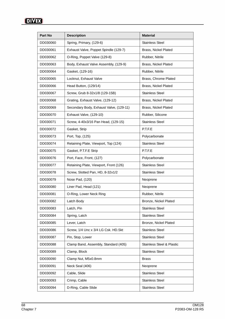
68 OM128Chapter 7 P2083-OM-128 R5
DD030060 Spring, Primary, (129-6) Stainless Steel
DD030061 Exhaust Valve, Poppet Spindle (129-7) Brass, Nickel Plated
DD030062 O-Ring, Poppet Valve (129-8) Rubber, Nitrile
DD030063 Body, Exhaust Valve Assembly, (129-9) Brass, Nickel Plated
DD030064 Gasket, (129-16) Rubber, Nitrile
DD030065 Locknut, Exhaust Valve Brass, Chrome Plated
DD030066 Head Button, (129/14) Brass, Nickel Plated
DD030067 Screw, Grub 8-32x1/8 (129-15B) Stainless Steel
DD030068 Grating, Exhaust Valve, (129-12) Brass, Nickel Plated
DD030069 Secondary Body, Exhaust Valve, (129-11) Brass, Nickel Plated
DD030070 Exhaust Valve, (129-10) Rubber, Silicone
DD030071 Screw, 4-40x3/16 Pan Head, (129-15) Stainless Steel
DD030072 Gasket, Strip P.T.F.E
DD030073 Port, Top, (125) Polycarbonate
DD030074 Retaining Plate, Viewport, Top (124) Stainless Steel
DD030075 Gasket, P.T.F.E Strip P.T.F.E
DD030076 Port, Face, Front, (127) Polycarbonate
DD030077 Retaining Plate, Viewport, Front (126) Stainless Steel
DD030078 Screw, Slotted Pan, HD, 8-32x1/2 Stainless Steel
DD030079 Nose Pad, (120) Neoprene
DD030080 Liner Pad, Head (121) Neoprene
DD030081 O-Ring, Lower Neck Ring Rubber, Nitrile
DD030082 Latch Body Bronze, Nickel Plated
DD030083 Latch, Pin Stainless Steel
DD030084 Spring, Latch Stainless Steel
DD030085 Lever, Latch Bronze, Nickel Plated
DD030086 Screw, 1/4 Unc x 3/4 LG Csk. HD.Skt Stainless Steel
DD030087 Pin, Stop, Lower Stainless Steel
DD030088 Clamp Band, Assembly, Standard (405) Stainless Steel & Plastic
DD030089 Clamp, Block Stainless Steel
DD030090 Clamp Nut, M5x0.8mm Brass
DD030091 Neck Seal (406) Neoprene
DD030092 Cable, Slide Stainless Steel
DD030093 Crimp, Cable Stainless Steel
DD030094 D-Ring, Cable Slide Stainless Steel
Part No Description Material
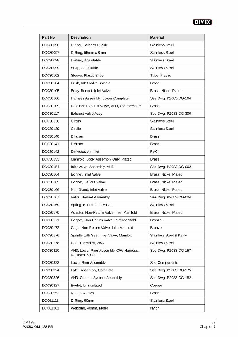
OM128 69P2083-OM-128 R5 Chapter 7
DD030096 D-ring, Harness Buckle Stainless Steel
DD030097 D-Ring, 55mm x 8mm Stainless Steel
DD030098 D-Ring, Adjustable Stainless Steel
DD030099 Snap, Adjustable Stainless Steel
DD030102 Sleeve, Plastic Slide Tube, Plastic
DD030104 Bush, Inlet Valve Spindle Brass
DD030105 Body, Bonnet, Inlet Valve Brass, Nickel Plated
DD030106 Harness Assembly, Lower Complete See Dwg. P2083-DG-164
DD030109 Retainer, Exhaust Valve, AH3, Overpressure Brass
DD030117 Exhaust Valve Assy See Dwg. P2083-DG-300
DD030138 Circlip Stainless Steel
DD030139 Circlip Stainless Steel
DD030140 Diffuser Brass
DD030141 Diffuser Brass
DD030142 Deflector, Air Inlet PVC
DD030153 Manifold, Body Assembly Only, Plated Brass
DD030154 Inlet Valve, Assembly, AH5 See Dwg. P2083-DG-002
DD030164 Bonnet, Inlet Valve Brass, Nickel Plated
DD030165 Bonnet, Bailout Valve Brass, Nickel Plated
DD030166 Nut, Gland, Inlet Valve Brass, Nickel Plated
DD030167 Valve, Bonnet Assembly See Dwg. P2083-DG-004
DD030169 Spring, Non-Return Valve Stainless Steel
DD030170 Adaptor, Non-Return Valve, Inlet Manifold Brass, Nickel Plated
DD030171 Poppet, Non-Return Valve, Inlet Manifold Bronze
DD030172 Cage, Non-Return Valve, Inlet Manifold Bronze
DD030176 Spindle with Seat, Inlet Valve, Manifold Stainless Steel & Kel-F
DD030178 Rod, Threaded, 2BA Stainless Steel
DD030320 AH3, Lower Ring Assembly, C/W Harness, Neckseal & Clamp
See Dwg. P2083-DG-157
DD030322 Lower Ring Assembly See Components
DD030324 Latch Assembly, Complete See Dwg. P2083-DG-175
DD030326 AH3, Comms System Assembly See Dwg. P2083-DG-182
DD030327 Eyelet, Uninsulated Copper
DD030552 Nut, 8-32, Hex Brass
DD061113 D-Ring, 50mm Stainless Steel
DD061301 Webbing, 48mm, Metre Nylon
Part No Description Material
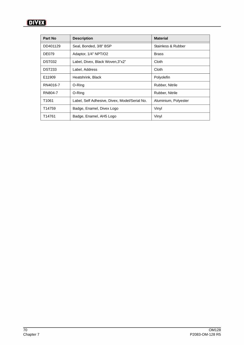
70 OM128Chapter 7 P2083-OM-128 R5
DD401129 Seal, Bonded, 3/8” BSP Stainless & Rubber
DE079 Adaptor, 1/4” NPT/O2 Brass
DST032 Label, Divex, Black Woven,3”x2” Cloth
DST233 Label, Address Cloth
E11909 Heatshrink, Black Polyolefin
RN4016-7 O-Ring Rubber, Nitrile
RN804-7 O-Ring Rubber, Nitrile
T1061 Label, Self Adhesive, Divex, Model/Serial No. Aluminium, Polyester
T14759 Badge, Enamel, Divex Logo Vinyl
T14761 Badge, Enamel, AH5 Logo Vinyl
Part No Description Material
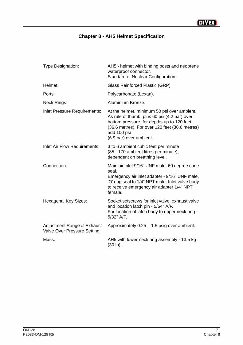
OM128 71P2083-OM-128 R5 Chapter 8
Chapter 8 - AH5 Helmet Specification
Type Designation: AH5 - helmet with binding posts and neoprene waterproof connector.Standard of Nuclear Configuration.
Helmet: Glass Reinforced Plastic (GRP)
Ports: Polycarbonate (Lexan).
Neck Rings: Aluminium Bronze.
Inlet Pressure Requirements: At the helmet, minimum 50 psi over ambient. As rule of thumb, plus 60 psi (4.2 bar) over bottom pressure, for depths up to 120 feet (36.6 metres). For over 120 feet (36.6 metres) add 100 psi (6.9 bar) over ambient.
Inlet Air Flow Requirements: 3 to 6 ambient cubic feet per minute (85 - 170 ambient litres per minute), dependent on breathing level.
Connection: Main air inlet 9/16" UNF male. 60 degree cone seal.Emergency air inlet adapter - 9/16" UNF male, 'O' ring seal to 1/4" NPT male. Inlet valve body to receive emergency air adapter 1/4" NPT female.
Hexagonal Key Sizes: Socket setscrews for inlet valve, exhaust valve and location latch pin - 5/64" A/F.For location of latch body to upper neck ring - 5/32" A/F.
Adjustment Range of Exhaust Valve Over Pressure Setting:
Approximately 0.25 – 1.5 psig over ambient.
Mass: AH5 with lower neck ring assembly - 13.5 kg (30 lb).

72 OM128Chapter 8 P2083-OM-128 R5
(Intentionally Blank)

OM128 73P2083-OM-128 R5 Chapter 9
Chapter 9 - AH5 Helmet Drawings
Part No Description Drawing No
DD030342 AH5 Helmet & Harness Assembly P2083-DG-001
DD030154 Inlet Valve Assembly P2083-DG-002
DD030163 Main Air Valve Bonnet Assembly P2083-DG-003
DD030167 Bailout Valve Bonnet Assembly P2083-DG-004
DD030117 Exhaust Valve Assembly P2083-DG-005
DD030324 Latch Assembly P2083-DG-006

74 OM128Chapter 9 P2083-OM-128 R5
(Intentionally Blank)