ST51A/ST75A/ST75AV Installation, Operation & Maintenance ...
Upload
khangminh22Category
view
2download
0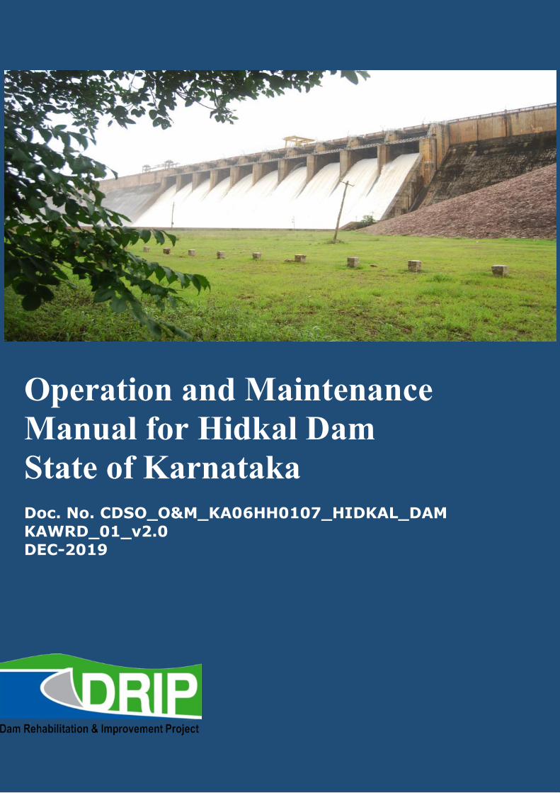
Guidelines for Instrumentation of Large Dams September 2016
Operation and Maintenance Manual for Hidkal Dam State of Karnataka
Doc. No. CDSO_O&M_KA06HH0107_HIDKAL_DAM KAWRD_01_v2.0 DEC-2019
O&M Manual for Hidkal Dam December-2019
Front Cover Photograph: Downstream view of Hidkal Dam during flood release Rrehabilitation works carried out under the Dam Rehabilitation & Improvement Project (DRIP)entailed multiple contracts for works carried out to1) reduce seepage on dyke no 1 at Ch 5+100M TO 5+300M doing curtain grouting at upstream side of the Dyke.2) For security purpose barbed wire fencing to Dyke no 1, constructing new monitoring building near Indira Gandhi circle also re-carpeting to the downstream service road.3) Providing New Emergency gate for irrigation sluice re fabrication of gates with embedded parts including hoist mechanism, providing shelter over hoists of sluice service gates and radial gates.4)Providing Special masonry repairs to upstream side by Poly ironite ceramic cementa-tions(PICC) mortar and to arrest leakages and strengthening of dam ch 8500’ to 10000’ and also providing M-60 concrete to the stilling basin for strengthening of stilling basin.5)Providing and fixing water proofing lighting with water proofing cable arrangements to the drainage gallery also illumination to the main dam 6) Fixing of CCTV system for crest gates, dam entry/exit, Ib and other important and crucial points in the view of security of Hidkal dam..
O&M Manual for Hidkal Dam December-2019
Doc. No. CDCO_O&M_KA06HH0107_Hidkal Dam_v2.0 Page i
Operation and Maintenance Manual for Hidkal Dam
Prepared by the Dam Safety Rehabilitation Directorate
with Assistance from
KARNATAKA NEERAVARI NIGAM LIMITED
(A Government of Karnataka undertaking)
State of Karnataka
4th floor, Coffee Board Building, No.1, Dr. B.R Ambedkar Veedhi Infantry Road, Bengaluru 560001
December-2019
O&M Manual for Hidkal Dam December-2019
Doc. No. CDCO_O&M_KA06HH0107_Hidkal Dam_v2.0 Page ii
MESSAGE
India has more than 5200 large dams. Their health and safety are of paramount importance for
sustainable use of the valuable assets, besides providing protection to the people and property in
the downstream areas. The Ministry of Water Resources, River Development & Ganga Rejuve-
nation through the Central Water Commission (CWC), with financial assistance from the World
Bank, started the Dam Rehabilitation and Improvement Project (DRIP) to rehabilitate 198 large
dam projects in seven states.
For managing a dam in a sustainable and scientific manner, it is very crucial for each dam owner
to have dam specific Operation and Maintenance Manual that lays down procedures for the daily
upkeep of the dam. An Operation and Maintenance Manual for a dam is essential for ensuring its
safe functioning and for deriving continued benefits. This Operation and Maintenance Manual
for Hidkal Dam has been prepared following the Guideline for Preparation Operation and
Maintenance Manuals published in January 2018 under DRIP and covers requirements for
project Operation, Inspection, Maintenance, Instrumentation and Monitoring the health of
Hidkal Dam both during monsoon and non-monsoon periods.
I recommend the dam officials to use this manual for the efficient and safe Operation and
Maintenance of the Hidkal Dam on regular basis.
I compliment all the experts who have contributed to the development of this manual and con-
gratulate the Ministry of Water Resources, River Development & Gang Rejuvenation, CWC for
the initiation of such important policy protocol to address dam safety management in India.
Shri. Rakesh Singh, IAS
Principal Secretary
Water Resources Department, Karnataka
O&M Manual for Hidkal Dam December-2019
Doc. No. CDCO_O&M_KA06HH0107_Hidkal Dam_v2.0 Page iii
THIS PAGE LEFT BLANK INTENTIONALLY
O&M Manual for Hidkal Dam December-2019
Doc. No. CDCO_O&M_KA06HH0107_Hidkal Dam_v2.0 Page iv
FORWARD
This Operation and Maintenance (O&M) Manual developed exclusively for Hidkal Dam is a de-
tailed set of written descriptions with step-by-step procedures for ensuring that the dam is safely
operated, frequently inspected and properly maintained. In this era of shrinking budgets, timely
inspection and preventative maintenance is necessary for the safe functioning of the dam and
continued productive use of the dam and reservoir.
The format of this manual was prepared following the principles published 2018 CWC guidelines
for operation and maintenance of dam for the use by all Dam Owners in developing their own
site-specific manuals. Each section of the documen tprovides the necessary instructions to oper-
ate, inspect and maintain their dam.
It is recommended that all dam officials charged with the operation of their dams to use this
manual to ensure their dam is operated and maintained in a sustainable manner and will continue
to derive benefits.
O&M Manual for Hidkal Dam December-2019
Doc. No. CDCO_O&M_KA06HH0107_Hidkal Dam_v2.0 Page v
Team Involved in Preparing this Manual O&M Manual
Aravind Kanagil Chief Engineer, KNNL, Irrigation North, Belagavi.
Shri C. D. Patil Superintending Engineer, KNNL, GRBC Circle, Hidkal Dam
Shri S.C.Naik Executive Engineer, KNNL, GRBC Division, Hidkal Dam.
Shri S.M.Madiwale Assistant Executive engineer, KNNL, CBC Sub Division No 2, Hidkal DAM
Shri S R Kamat Junior Engineer, KNNL, CBC Sub Division No 2, Hidkal Dam (Draft Development)
O&M Manual for Hidkal Dam December-2019
Doc. No. CDCO_O&M_KA06HH0107_Hidkal Dam_v2.0 Page vi
TABLE OF CONTENTS MESSAGE ................................................................................................................................. II
FORWARD ................................................................................................................................ IV
LIST OF FIGURES ..................................................................................................................... VI
CHAPTER 1. - GENERAL INFORMATION ....................................................................................... 1
1.1 Introduction ............................................................................................................ …...1
1.2 Purpose, Location & Description of Hidkal Dam ........................................................... 1
1.3 Background Details of the Project .................................................................................. 2
1.3.1 Hydrology of Ghataprabha project .................................................................... 3
1.3.2 Dam site Location:: ........................................................................................... 4
1.3.3 Main Design Features and Components of Hidkal Dam: .................................. 8
1.4 Salient Features of Hidkal Dam ...................................................................................... 9
1.5 Assignment of Responsibility ....................................................................................... 10
1.5.1 Roles and Responsibilities of the AEE and AE during Monsoon ..................... 12
1.5.2 Roles and Responsibilities of the SE and EE during Monsoon ........................ 13
1.5.3 Roles and Responsibilities of the Chief Engineer during Monsoon ................. 13
1.6 Collection & Reporting of Dam and Reservoir Data ..................................................... 14
1.7 Public and Project Staff - Health and Safety .................................................................. 16
1.7.1 Restricted Areas .............................................................................................. 16
1.7.2 Details of the Security arrangements at Hidkal Dam Site. ............................... 16
1.8 Staff Position, Communication & Warning System ....................................................... 19
1.8.1 Schedule of General Duties for Project Engineers .................................. 22 to 24
1.8.2 Hydro-Mechanical Inspections / Checks ............................................... 25to 27
1.9 Distribution of Operation & Maintenance Manuals ...................................................... 29
1.10 Supporting Documents & Reference Material............................................................... 29
CHAPTER 2. PROJECT OPERATION ..................................................................................... 31
2.1 Basic Data .................................................................................................................... 31
2.1.1 Area Capacity curves. ...................................................................................... 31
2.1.2 Latest Design flood & features related to safety .............................................. 33
2.2 Flood Management at Hidkal Reservoirs ..................................................................... 33
2.2.1 Gate Operations: ............................................................................................. 33
2.2.2 Rule Curve .......................................................... Error! Bookmark not defined.
2.2.3 Recommended gates operation procedure for normal flow condition… 34
2.2.4 Sequence of Opening or Closing of Gates. ..................................................... 355
O&M Manual for Hidkal Dam December-2019
Doc. No. CDCO_O&M_KA06HH0107_Hidkal Dam_v2.0 Page vii
2.2.5 Inflow Forecasting .......................................................................................... 36
2.2.6 Tables of discharge for crest gates ............................................................. 36-38
2.3 Operation of Radial Crest Gates of Hidkal Dam ........................................................... 42
2.3.1 Brief Description. ...................................................................................... 42-43
2.3.2 Radial Crest Gates – Technical Data ............................................................... 43
2.3.3 Salient Features ............................................................................................... 44
2.3.4 Material Specification ................................................................................ 43-44
2.4 Operating gates ............................................................................................................ 45
2.4.1 Operating system……………………………………………………………..44
2.4.2 Checklist before operations………………………………………………..44
2.4.4 Trouble shooting …………………………………………………………….45
2.4.5 Intake service Gates ......................................................................................... 46
2.4.6 Intake emergencey gate ....................................... Error! Bookmark not defined.
2.4.7 Emergency operation ………………………………………………………………………………….47
2.5 Reservoir level………………………………………………………………..47
2.6 Stoplogs ........................................................................................................................ 48
2.6.1 Brief Description ............................................................................................. 48
2.6.2 Technical Data ................................................................................................ 48
2.6.3 Material Specifications .................................................................................... 49
2.6.4 Instructions Before Operating the Stoplog Gate .............................................. 49
2.7 Handling Equipment ................................................................................................... 50
2.7.1 20-T Gantry Crane – Brief Description ............................................................ 50
2.7.2 Technical Data ................................................................................................ 50
2.7.3 Material Specifications .................................................................................... 52
2.7.4 Operational Instructions ................................................................................. 53
2.7.5 TROUBLE SHOOTING ................................................................................ 53
2.7.5.1 Motor ....................................................................................................... 53-54
2.7.5.2 E.M. BRAKE ............................................................................................... 54
2.7.5.3 Thrustor Brake .............................................................................................. 54
2.8 outlet works………………………………………………………………………54
2.8.1 Description…………………………………………………………………..54
2.8.1.1 Head regulator……………………………………………………………54
2.8.1.2 Head works………………………………………………………………..54
2.8.2 Historical events…………………………………………………………….55
O&M Manual for Hidkal Dam December-2019
Doc. No. CDCO_O&M_KA06HH0107_Hidkal Dam_v2.0 Page viii
2.8.3 Operations…………………………………………………………………..55
2.8.3.1 General……………………………………………………………………55
2.8.3.2 Restrictions………………………………………………………………..55
2.8.3.3 Mechanical………………………………………………………………..55
2.8.4 Reference…………………………………………………………………..55
2.8.4.1 Reports and data……………………………………………………..…...55
2.8.4.2 Drawings……………………………………………………………………55
2.9 Power outlet: ............................................................................................................. 56
2.9.1 Discription……………………………………………………………….56-57
2.9.2 General………………………………………………………………………57
2.9.3 Deficiences and problems………………………………………………… 57
2.9.4 Hydrolic design………………………………………………………….…..57
2.9.5 Normal operations…………………………………………………………..57
2.9.6 Used with excavation of reservoir………………………………………….57
2.10 Operations. ................................................................................................................... 58
2.10.1 General: ........................................................................................................... 58
2.10.2 Restrictions: ................................................................................................... 58
2.10.3 Mechanical: .................................................................................................... 58
2.10.4 Flood and emergencey conditions: .............................................................. 58
2.11 Access Roads ................................................................................................................ 58
2.11.1 Description ..................................................................................................... 58
2.11.2 Condition ........................................................................................................ 58
2.11.3 General road is in good condition .................................................................... 58
2.12 Record keeping ............................................................................................................ 59
CHAPTER 3 - PROJECT INSPECTIONS ......................................................................................... 60
3.1 Types of Inspections..................................................................................................... 60
3.1.1 Comprehensive Evaluation Inspections ..................................................... 60-61
3.1.2 Scheduled Inspections ..................................................................................... 61
3.1.3 Special (Unscheduled) Inspections............................................................ 61-62
3.1.4 Informal Inspections ....................................................................................... 62
3.2 Pre- and Post-Monsoon Checklist and Example of Report Proformas ..................... 63-71
CHAPTER 4 - PROJECT MAINTENANCE ..................................................................................... 72
4.1 Maintenance Priorities .................................................................................................. 72
4.1.1 Immediate Maintenance ........................................................................... 72-73
O&M Manual for Hidkal Dam December-2019
Doc. No. CDCO_O&M_KA06HH0107_Hidkal Dam_v2.0 Page ix
4.1.2 Preventive Maintenance .................................................................................. 73
4.1.2.1 Condition Based Maintenance ........................................................................ 73
4.1.2.2 Routine Maintenance ................................................................................ 73-74
4.2 Procedures for Routine Maintenance ............................................................................ 74
4.2.1 Earthwork ................................................................................................. 74-77
4.2.2 Masonry / Concrete Dams & Spillways ........................................................... 78
4.2.3 River Sluices .................................................................................................... 78
4.2.4 Gates & Hoisting Equipment .................................................................... 79-81
4.2.5 Electrically operated fixed hoists ............................................................... 81-83
4.3 Maintenance of electrical components of fixed rope drum hoists……………83-84
4.3.1 Spillway stoplogs, lifting beam and radial gate……………………….85-88
4.3.2 Additional maintenance items for stoplogs……………………………88-89
4.4 Maintenance of bearing……………………………………………………………89
4.5 Surface preparation and painting of HM works……………………………..90-93
4.6 Electrical system………………………………………………………………….93
4.7 Maintenance of metal gate components…………………………………………94
4.8 Access roads……………………………………………………………………….94
4.9 General cleaning…………………………………………………………………..94
4.10 Material and establishment requirement during monsoon period…………..94
4.11 General list of maintenance records……………………………………………95
4.12 Preparation of O & M budget……………………………………….……...95-97
4.13 Maintenance records……………………………………………………………97
CHAPTER 5 - INSTRUMENTATION AND MONITORING ................................................................ 98
5.1 Dam Instrumentation· ..................................................................................................... 98
5.1.1 General Information ........................................................................................ 98
5.1.2 Embedded Instruments – Concrete/Masonry ................................................. 98
5.1.3 Instruments Embedded in the Hidkal Earthen Dam ....................................... 99
5.1.4 Seismological Observations ..................................................................... 99-100
CHAPTER 6 - PREVIOUS REHABILITATION EFFORTS .......................................................... 101-102
CHAPTER 7 - UPDATING THE MANUAL ................................................................................... 103
APPENDIX 1 – BASIC DRAWINGS OF HIDKAL DAM .............................................................. 104-109
APPENDIX 2― KEY ELEMENTS OF HIDKAL DAM EAP ........................................................ 110-115
APPENDIX 3 ― MATERIAL REQUIRED FOR MAINTENANCE DURING MONSOON ......................... 116
APPENDIX 4 ― SCHEDULED OR UNSCHEDULED DAM SAFETY INSPECTION FORM ............... 117-129
APPENDIX 5 – HYDRAULIC OIL SERVICING AND MAINTENANCE INSTRUCTIONS ...................... 130
O&M Manual for Hidkal Dam December-2019
Doc. No. CDCO_O&M_KA06HH0107_Hidkal Dam_v2.0 Page x
APPENDIX 6 - GLOSSARY ................................................................................................... 131-137
List of Tables
Table 1 – Overall Responsibilities for Hidkal Dam 11
Table 2 – Roles & Responsibilities of AEE & AE 12
Table 3– Roles & Responsibilities of SE & EE 13
Table 4– Roles & Responsibilities of the Chief Engineer 13
Table 5– Example Proforma for recording Flow Data 15
Table 6 - Distribution of O&M Manual and Revisions 29
Table 7 – Rate of change in storage at Hidkal dam 31-32
Table 8 – Rule curve 34
Table 9 - Discharges for the Crest Gates (Part 1 of 2) 36-38
Table 10 - Stoplog Data 48
Table 11 - Material Specifications 49
Table 12 - Hidkal Dam 20-Ton Gantry Crane Design Data 50
Table 13 – Technical Details of Important Machinery Items 51-52
Table 14 – Materials for 20-Ton Gantry Crane 52
Table 15 – Troubleshooting for Motors 53
Table 16 - O&M BUDGET COSTS (ANNUAL) 95-97
Table 17 - Locations and Extents of Structural Members 98
Table 18 - Embedded Instruments (Statement No. 1 & No. 111) 98
Table 19 - Embankment Instruments at Ch. 360.00 meters (Statement No. 11) 99
LIST OF FIGURES
Figure 1 - Krishna Basin Map ............................................................................................................... 4
Figure 2 - Overhead Image of Hidkal Dam .......................................................................................... 6
Figure 3 Layout of Hidkal Dam Premises .......................................................................................... 17
Figure 4 - Organisation Chart ............................................................................................................ 21
Figure 5 – Reserviour operation chart of hidkal dam ...................................................................... 31
O&M Manual for Hidkal Dam December-2019
Doc. No. CDCO_O&M_KA06HH0107_Hidkal Dam_v2.0 Page xi
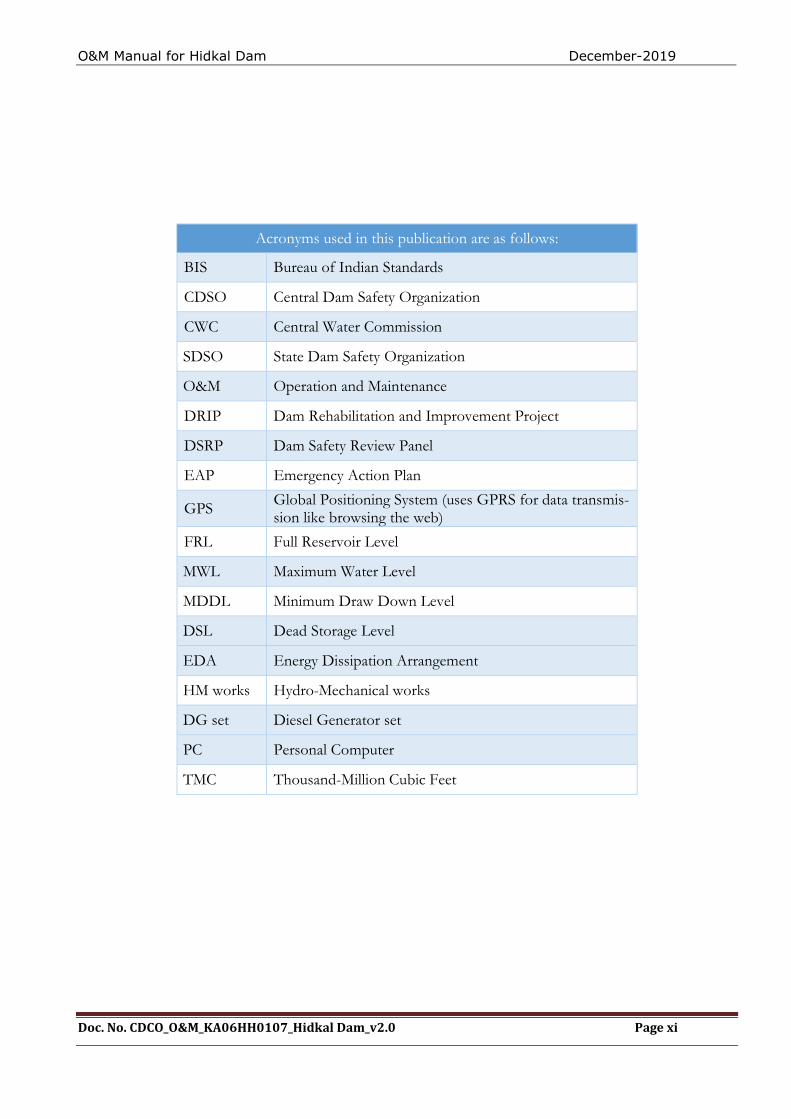
Acronyms used in this publication are as follows:
BIS Bureau of Indian Standards
CDSO Central Dam Safety Organization
CWC Central Water Commission
SDSO State Dam Safety Organization
O&M Operation and Maintenance
DRIP Dam Rehabilitation and Improvement Project
DSRP Dam Safety Review Panel
EAP Emergency Action Plan
GPS Global Positioning System (uses GPRS for data transmis-sion like browsing the web)
FRL Full Reservoir Level
MWL Maximum Water Level
MDDL Minimum Draw Down Level
DSL Dead Storage Level
EDA Energy Dissipation Arrangement
HM works Hydro-Mechanical works
DG set Diesel Generator set
PC Personal Computer
TMC Thousand-Million Cubic Feet

O&M Manual for Hidkal Dam December-2019
Doc. No. CDCO_O&M_KA06HH0107_Hidkal Dam_v2.0 Page xii
THIS PAGE BLANK LEFT INTENTIONALLY
O&M Manual for Hidkal Dam December-2019
Doc. No. CDCO_O&M_KA06HH0107_Hidkal Dam_v2.0 Page 1
CHAPTER 1. - GENERAL INFORMATION
1.1 Introduction
This document represents a detailed Operation and Maintenance (O&M) Manual for Hidkal Dam, Karnataka, providing written descriptions of procedures for ensuring that the dam oper-ates safely and is kept in a good condition by periodic inspections, repairs, and maintenance in a sustainable manner. Timely maintenance is important for the continued safe functioning and productive use of the dam and reservoir.
The Manual has been prepared primarily for the dam operation’s staff and their supervisors who are assigned the responsibility for the physical operations and maintenance of the dam. It con-tains, as a minimum, all information and instructions necessary for them to perform their allotted tasks in a safe manner. In addition to instructions for dam operations staff, the Manual includes all necessary instructions for other staff directly or indirectly involved in operating and maintain-ing the dam.
It is essential that the Manual or a copy of the Manual along with supporting data including the atlas of all drawings and manufacturer’s technical documents is available at site for ready refer-ence.
1.2 Purpose, Location & Description of Hidkal Dam
This river being an inter-state river, water utilization as of now is in accordance with the KWDT (Krishna Water Disputes Tribunal) award of 1976 based on the estimated 75% dependable yield with return flows. The water allocated to Karnataka was 734 TMC. Government of Karnataka has approved a Master plan to utilize 734 TMC of water in Krishna basin. Out of this, an alloca-tion made for Ghataprabha Project is 2412.86 MCM (85.20 TMC).
In Krishna basin, major Irrigation Projects such as Ghataprabha Project and Malaprabha Project were taken up for implementation, to provide irrigation facilities to the drought prone areas of Dharwad and Belgaum Districts; Reservoirs were constructed across the Rivers Ghataprabha and Malaprabha. Gravity canal network and lift irrigation schemes were provided in the com-mand area.
The river Ghataprabha with its main tributaries namely Hiranyakeshi, Tamrapani, and Mar-kandeya is one of the principal rivers of northern part of Karnataka State. It has substantial water resources. The river originates in Western Sahyadri range near Amboli and flows generally in an easterly direction for al length of 260 Kilo Meters before joining the river Krishna, in Bijaprur District. It has good Ghat fed catchment with an assured rainfall varying from about 6,250 mm to 1,000 mm and drains annually about 28 TMC of water. During summer, the river gradually dwindles down to a streamlet like all other Deccan Rivers. Even though, the rainfall in the Ghat area is assured and plentiful, it is scanty and untimely in the eastern part of the valley. Eastern part of Belgaum District and the whole of Bijapur District lies in arid zone and area, therefore, frequently subjected to famine. The agriculture is the main occupation of the population of the area and the irrigation facilities will go a long way in achieving the prosperity of the area. Hence, efforts were made to utilize the water of Ghataprabha river and its tributaries.
KWDT – II award passed in December 2010, based on assessed 65 % dependable yield and sur-plus yield Distributed water to Karnataka is given in Table-1
O&M Manual for Hidkal Dam December-2019
Doc. No. CDCO_O&M_KA06HH0107_Hidkal Dam_v2.0 Page 2
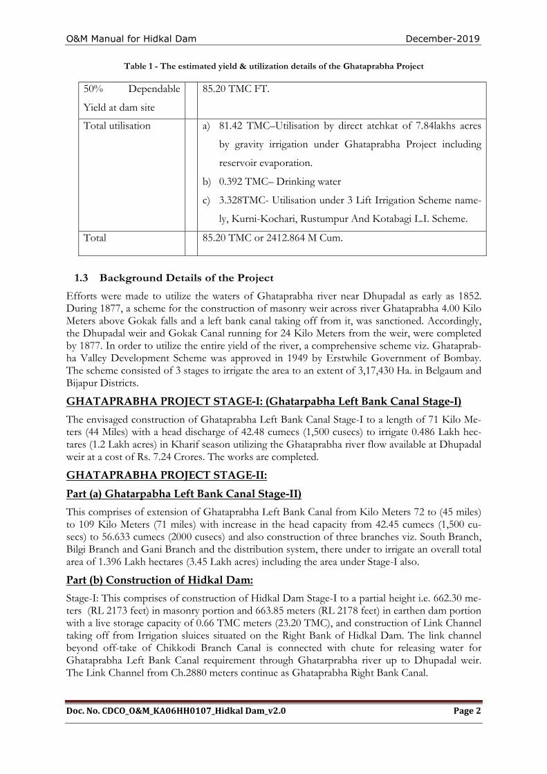
Table 1 - The estimated yield & utilization details of the Ghataprabha Project
50% Dependable
Yield at dam site
85.20 TMC FT.
Total utilisation a) 81.42 TMC–Utilisation by direct atchkat of 7.84lakhs acres
by gravity irrigation under Ghataprabha Project including
reservoir evaporation.
b) 0.392 TMC– Drinking water
c) 3.328TMC- Utilisation under 3 Lift Irrigation Scheme name-
ly, Kurni-Kochari, Rustumpur And Kotabagi L.I. Scheme.
Total 85.20 TMC or 2412.864 M Cum.
1.3 Background Details of the Project
Efforts were made to utilize the waters of Ghataprabha river near Dhupadal as early as 1852. During 1877, a scheme for the construction of masonry weir across river Ghataprabha 4.00 Kilo Meters above Gokak falls and a left bank canal taking off from it, was sanctioned. Accordingly, the Dhupadal weir and Gokak Canal running for 24 Kilo Meters from the weir, were completed by 1877. In order to utilize the entire yield of the river, a comprehensive scheme viz. Ghataprab-ha Valley Development Scheme was approved in 1949 by Erstwhile Government of Bombay. The scheme consisted of 3 stages to irrigate the area to an extent of 3,17,430 Ha. in Belgaum and Bijapur Districts.
GHATAPRABHA PROJECT STAGE-I: (Ghatarpabha Left Bank Canal Stage-I)
The envisaged construction of Ghataprabha Left Bank Canal Stage-I to a length of 71 Kilo Me-ters (44 Miles) with a head discharge of 42.48 cumecs (1,500 cusecs) to irrigate 0.486 Lakh hec-tares (1.2 Lakh acres) in Kharif season utilizing the Ghataprabha river flow available at Dhupadal weir at a cost of Rs. 7.24 Crores. The works are completed.
GHATAPRABHA PROJECT STAGE-II:
Part (a) Ghatarpabha Left Bank Canal Stage-II)
This comprises of extension of Ghataprabha Left Bank Canal from Kilo Meters 72 to (45 miles) to 109 Kilo Meters (71 miles) with increase in the head capacity from 42.45 cumecs (1,500 cu-secs) to 56.633 cumecs (2000 cusecs) and also construction of three branches viz. South Branch, Bilgi Branch and Gani Branch and the distribution system, there under to irrigate an overall total area of 1.396 Lakh hectares (3.45 Lakh acres) including the area under Stage-I also.
Part (b) Construction of Hidkal Dam:
Stage-I: This comprises of construction of Hidkal Dam Stage-I to a partial height i.e. 662.30 me-ters (RL 2173 feet) in masonry portion and 663.85 meters (RL 2178 feet) in earthen dam portion with a live storage capacity of 0.66 TMC meters (23.20 TMC), and construction of Link Channel taking off from Irrigation sluices situated on the Right Bank of Hidkal Dam. The link channel beyond off-take of Chikkodi Branch Canal is connected with chute for releasing water for Ghataprabha Left Bank Canal requirement through Ghatarprabha river up to Dhupadal weir. The Link Channel from Ch.2880 meters continue as Ghataprabha Right Bank Canal.
O&M Manual for Hidkal Dam December-2019
Doc. No. CDCO_O&M_KA06HH0107_Hidkal Dam_v2.0 Page 3
The works under Ghataprabha Project Stage-II i.e. Part (a) and (b) were completed in the year 1979-80 at cost of Rs. 64.15 Crores. The water impound in Hidkal Dam, is utilized for irrigation under Ghatarprabha Left Bank Canal command.
GHATAPRABHA PROJECT STAGE-III WORKS
The Ghataprabha Project Stage-III envisages following: -
(i) Raising the dam by 3.70 meters (12 feet) in Masonry Section to level 666.0 meters (RL
2185 feet) and 4.30 meters (14 feet) in earthen portion to level of 668.10 meters (2192’) and
F.R.L./M.W.L raised to 662.95 meters (2175 feet) to store (1440MCM) 51 TMC of water.
The storage is intended to feed Ghataprabha Left Bank Canal, Right Bank Canal and
Chikkodi Branch Canal.
(ii) Construction of Right Bank Canal and Chikkodi Branch Canal to irrigate 1,55,559
hectares (3,84,400 acres)
(iii) The lining of Ghataprabha Left Bank Canal including branches and distribution down to
0.56 cumecs (20 cusecs) to increase its discharging capacities and to save water by
minimizing seepage losses so as to irrigate additional area of 22,257 hectares (54,997 acres).
The Ghataprabha Project Stage-III works are under various stages and are under
progress.
1.3.1. HYDROLOGY OF GHATAPRABHA PROJECT:
Catchment: The river Ghataprabha has the catchment area of 1412 Square Kilo Meters
(545.00 Square Miles) up to Hidkal Dam. The rainfall varies from 6,250 mm (250”) to about
1,000 mm (40”). The catchment area is situated in extremely hilly country and it is mostly
covered by forest and shrub growth.
Rainfall: A rain gauge station is established at Daddi in the catchment area and it is
maintained by Central Water Commission.
Field at Dam site:The 75% dependable yield of Ghataprabha river at Hidkal Dam, is
worked out based on yields for 40 years i.e. from the year 1943-44 to 1982-83 and is 79.050
TMC which corresponds to the year 1952-53.
The 50% yield of Ghataprabha river at Hidkal Dam site is worked out based on the yield
details of 50 years i.e. from 1943-44 to 1982-83 and is 87.134 TMC.
Yield at Dhupadal weir: The average yield works out 116.50 TMC the 75%
dependable yield is 97.894 TMC or say 98 TMC.
A preliminary estimate of ground water potential is made by assuming the annual recharge of
ground water as 5% of precipitation plus 15% of irrigation supplies and the yield is worked
out to 17.95 TMC.
O&M Manual for Hidkal Dam December-2019
Doc. No. CDCO_O&M_KA06HH0107_Hidkal Dam_v2.0 Page 4
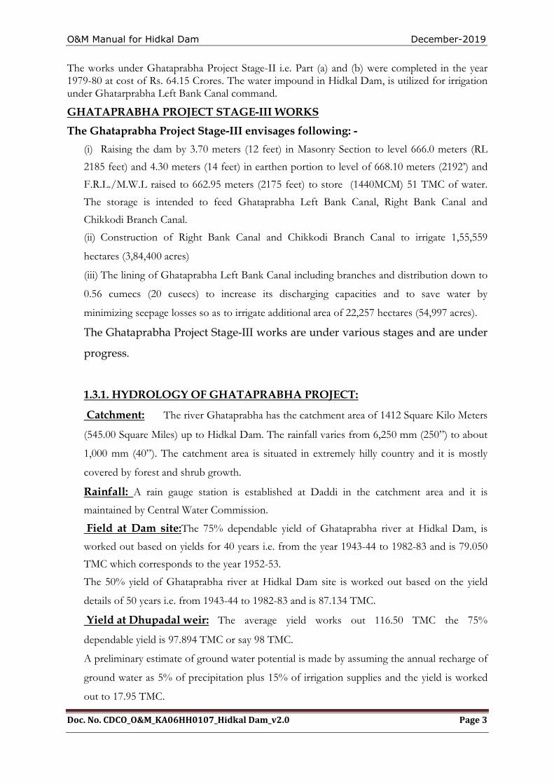
Utilization:
Sl.No Utilization Light Soil Heavy Soil
i Field application efficiency 65% 70%
ii Conveyance losses in distribution sys-
tem
25% 15%
iii - do – Main Canal 2 Cusecs per million Sq.ft of wetted perime-
ters. Including all losses are as given below.
1. For Ghatarprabha Left Bank Canal 38.006 TMC.
2. For Ghataprabha Right Bank Canal 36.524 TMC. including Chikkodi Branch Canal.
3. Foreshore Lift Irrigation Scheme 0.660 TMC. for Rehabilitations (4 Nos.). 75.190 TMC.
----------------- The annual utilization including evaporation losses of 3.24 TMC is 78.43 TMC.
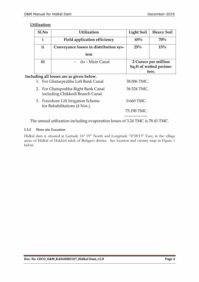
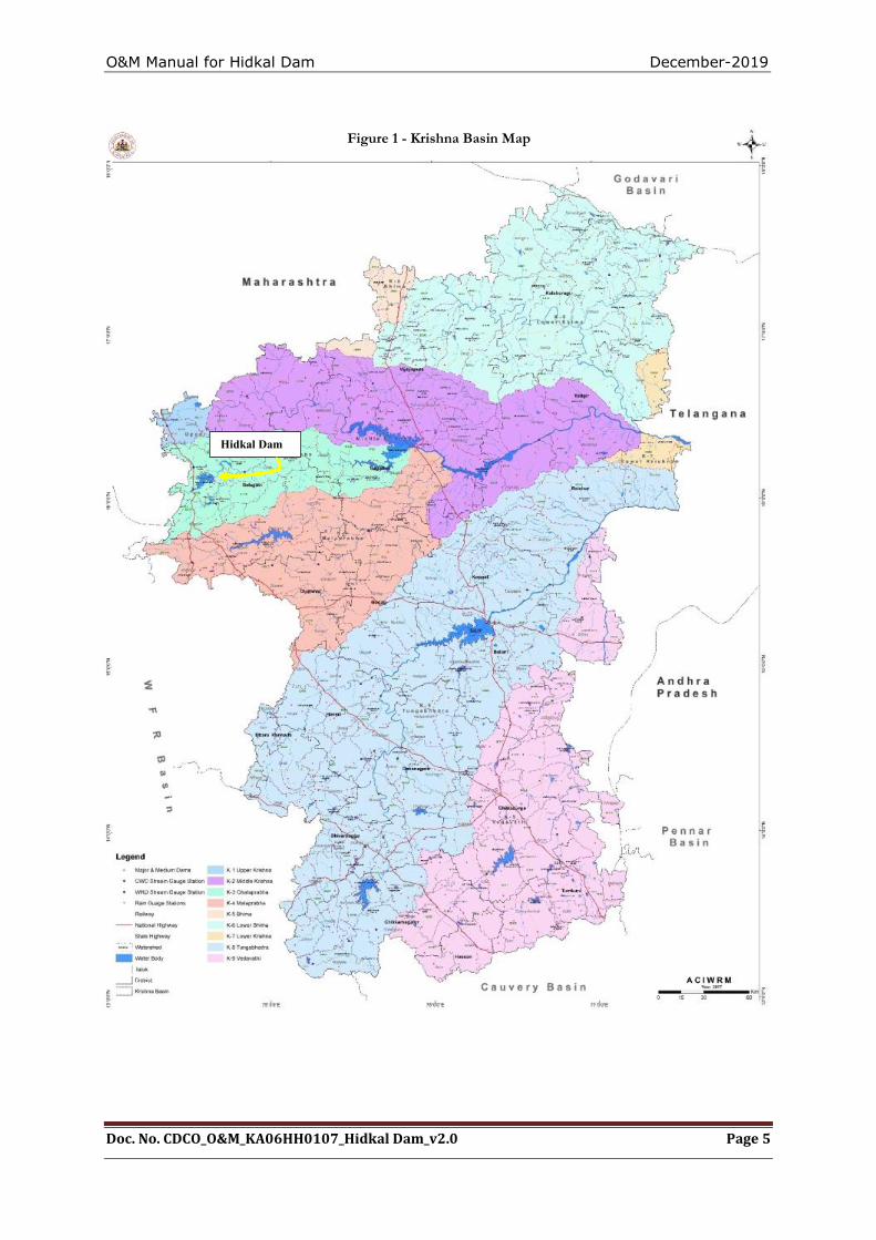
1.3.2 Dam site Location: Hidkal dam is situated at Latitude 16º 19” North and Longitude 74º38’15” East, in the village areas of Hidkal of Hukkeri taluk of Belagavi district. See location and vicinity map in Figure 1 below.
O&M Manual for Hidkal Dam December-2019
Doc. No. CDCO_O&M_KA06HH0107_Hidkal Dam_v2.0 Page 5
Hidkal Dam
Figure 1 - Krishna Basin Map

O&M Manual for Hidkal Dam December-2019
Doc. No. CDCO_O&M_KA06HH0107_Hidkal Dam_v2.0 Page 6
THIS PAGE LEFT BLANK INTENTIONALLY
O&M Manual for Hidkal Dam December-2019
Doc. No. CDCO_O&M_KA06HH0107_Hidkal Dam_v2.0 Page 7
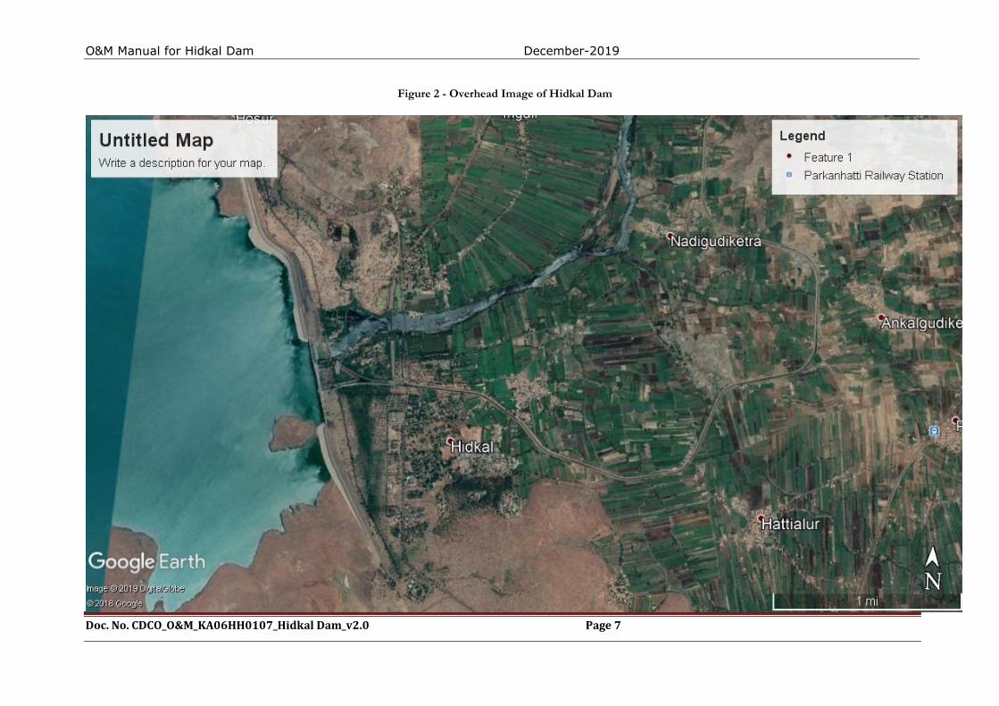
Figure 2 - Overhead Image of Hidkal Dam

O&M Manual for Hidkal Dam December-2019
Doc. No. CDCO_O&M_KA06HH0107_Hidkal Dam_v2.0 Page 8
THIS PAGE LEFT BLANK INTENTIONALLY
O&M Manual for Hidkal Dam December-2019
Doc. No. CDCO_O&M_KA06HH0107_Hidkal Dam_v2.0 Page 9
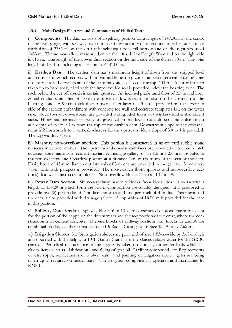
1.3.3 Main Design Features and Components of Hidkal Dam:
i) Components: The dam consists of a spillway portion for a length of 149.00m in the centre of the river gorge, with spillway, two non-overflow masonry dam sections on either side and an earth dam of 2286-m on the left flank including a rock fill portion and on the right side is of 1433 m. The non-overflow masonry dam on the left side is of length 50-m and on the right side is 613-m. The length of the power dam section on the right side of the dam is 50-m. The total length of the dam including all sections is 4481.00 m.
ii) Earthen Dam: The earthen dam has a maximum height of 26-m from the stripped level and consists of zonal sections with impermeable hearting zone and semi-permeable casing zone on upstream and downstream of the hearting zone, as also on the top 7.31-m. A cut-off trench taken up to hard rock, filled with the impermeable soil is provided below the hearting zone. The rock below the cut-off trench is curtain grouted. An inclined grade sand filter of 2.0-m and hori-zontal graded sand filter of 1.0-m are provided downstream and also on the upstream of the hearting zone. A 90-cm thick rip rap over a filter layer of 45-cm is provided on the upstream side of the earthen embankment with concrete toe wall and concrete templates i.e., on the water side. Rock toes on downstream are provided with graded filters at their base and embankment sides. Horizontal berms 3.0-m wide are provided on the downstream slope of the embankment at a depth of every 9.0-m from the top of the earthen dam. Downstream slope of the embank-ment is 2 horizontals to 1 vertical, whereas for the upstream side, a slope of 3.0 to 1 is provided. The top width is 7.5-m.
iii) Masonry non-overflow section: This portion is constructed in un-coursed rubble stone masonry in cement mortar. The upstream and downstream faces are provided with 0.65-m thick coursed stone masonry in cement mortar. A drainage gallery of size 1.6-m x 2.4-m is provided in the non-overflow and Overflow portion at a distance 1.50-m upstream of the axis of the dam. Drain holes of 45-mm diameter at intervals of 3-m c/c are provided in the gallery. A road way 7.5-m wide with parapets is provided. The non-earthen (both spillway and non-overflow sec-tions) dam was constructed in blocks. Non-overflow blocks 1 to 5 and 15 to 39.
iv) Power Dam Section: Six non-spillway masonry blocks from block Nos. 11 to 14 with a length of 156.20-m which form the power dam portion are suitably designed. It is proposed to provide five (2) penstocks of 7-m diameter each and one penstock of 4-m dia. This portion of the dam is also provided with drainage gallery. A top width of 10.00-m is provided for the dam in this portion.
v) Spillway Dam Section: Spillway blocks 6 to 10 were constructed of stone masonry except for the portion of the nappe on the downstream and the top portion of the crest, where the con-struction is of cement concrete. The end blocks of spillway portions viz., blocks 12 and 38 are combined blocks, i.e., they consist of ten (10) Radial Crest gates of Size 12.19-m by 7.62-m.
vi) Irrigation Sluices: Six (6) irrigation sluices are provided of size 1.83-m-wide by 3.65-m-high and operated with the help of a 10-T Gantry Crane. for the sluices release water for the GRBC canals. Periodical maintenance of these gates is taken up annually on tender basis which in-cludes items such as lubrication and filling of gear oil, Cardium compound, etc. Replacements of wire ropes, replacements of rubber seals and painting of irrigation sluice gates are being taken up as required on tender basis. The irrigation component is operated and maintained by KNNL.
O&M Manual for Hidkal Dam December-2019
Doc. No. CDCO_O&M_KA06HH0107_Hidkal Dam_v2.0 Page 10
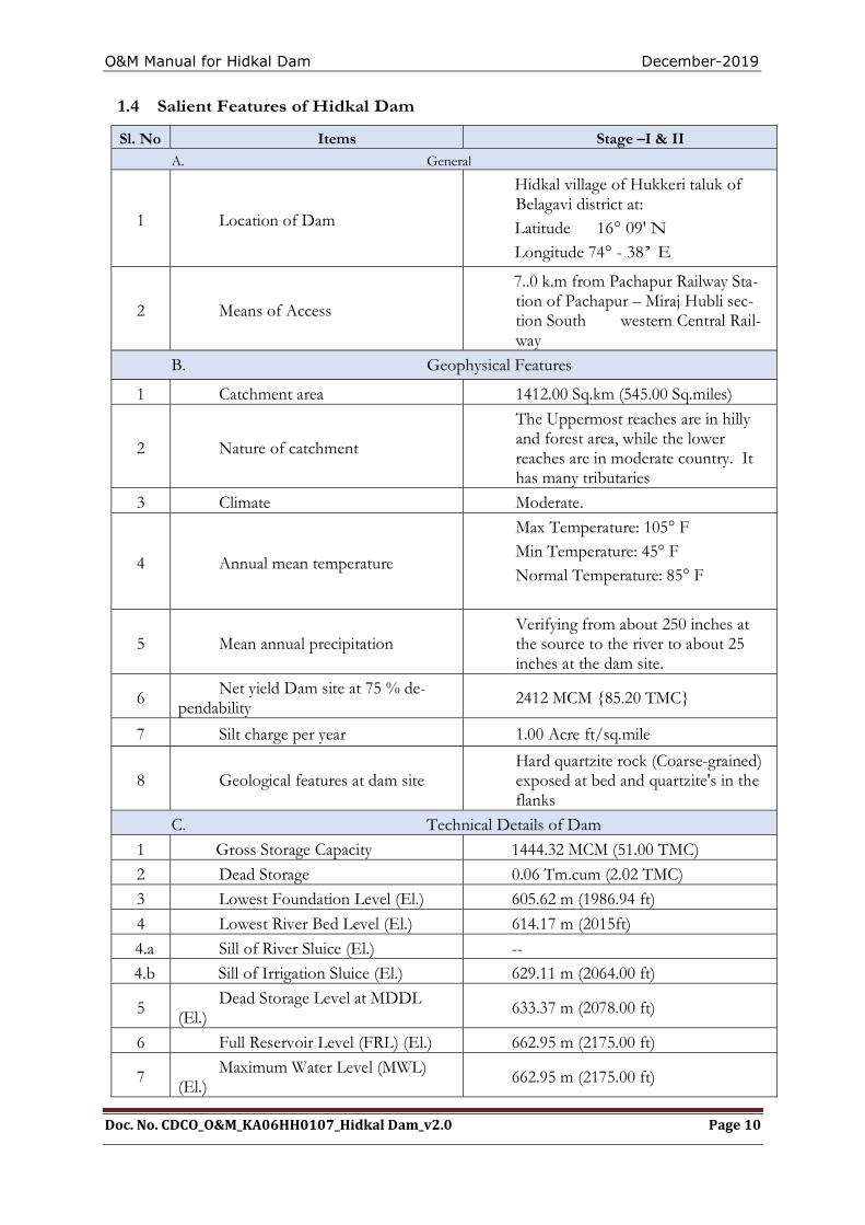
1.4 Salient Features of Hidkal Dam
Sl. No Items Stage –I & II A. General
1 Location of Dam
Hidkal village of Hukkeri taluk of Belagavi district at: Latitude 16° 09' N Longitude 74° - 38’ E
2 Means of Access
7..0 k.m from Pachapur Railway Sta-tion of Pachapur – Miraj Hubli sec-tion South western Central Rail-way
B. Geophysical Features
1 Catchment area 1412.00 Sq.km (545.00 Sq.miles)
2 Nature of catchment
The Uppermost reaches are in hilly and forest area, while the lower reaches are in moderate country. It has many tributaries
3 Climate Moderate.
4 Annual mean temperature
Max Temperature: 105° F Min Temperature: 45° F Normal Temperature: 85° F
5 Mean annual precipitation Verifying from about 250 inches at the source to the river to about 25 inches at the dam site.
6 Net yield Dam site at 75 % de-pendability
2412 MCM {85.20 TMC}
7 Silt charge per year 1.00 Acre ft/sq.mile
8 Geological features at dam site Hard quartzite rock (Coarse-grained) exposed at bed and quartzite's in the flanks
C. Technical Details of Dam
1 Gross Storage Capacity 1444.32 MCM (51.00 TMC)
2 Dead Storage 0.06 Tm.cum (2.02 TMC)
3 Lowest Foundation Level (El.) 605.62 m (1986.94 ft)
4 Lowest River Bed Level (El.) 614.17 m (2015ft)
4.a Sill of River Sluice (El.) --
4.b Sill of Irrigation Sluice (El.) 629.11 m (2064.00 ft)
5 Dead Storage Level at MDDL (El.) 633.37 m (2078.00 ft)
6 Full Reservoir Level (FRL) (El.) 662.95 m (2175.00 ft)
7 Maximum Water Level (MWL) (El.) 662.95 m (2175.00 ft)
O&M Manual for Hidkal Dam December-2019
Doc. No. CDCO_O&M_KA06HH0107_Hidkal Dam_v2.0 Page 11
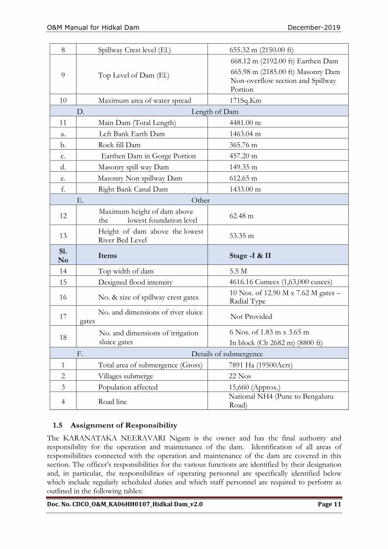
8 Spillway Crest level (El.) 655.32 m (2150.00 ft)
9 Top Level of Dam (El.)
668.12 m (2192.00 ft) Earthen Dam 665.98 m (2185.00 ft) Masonry Dam Non-overflow section and Spillway Portion
10 Maximum area of water spread 171Sq.Km
D. Length of Dam
11 Main Dam (Total Length) 4481.00 m
a. Left Bank Earth Dam 1463.04 m
b. Rock fill Dam 365.76 m
c. Earthen Dam in Gorge Portion 457.20 m
d. Masonry spill way Dam 149.35 m
e. Masonry Non spillway Dam 612.65 m
f. Right Bank Canal Dam 1433.00 m
E. Other
12 Maximum height of dam above the lowest foundation level 62.48 m
13 Height of dam above the lowest River Bed Level 53.35 m
Sl. No
Items Stage -I & II
14 Top width of dam 5.5 M
15 Designed flood intensity 4616.16 Cumecs (1,63,000 cusecs)
16 No. & size of spillway crest gates 10 Nos. of 12.90 M x 7.62 M gates – Radial Type
17 No. and dimensions of river sluice gates Not Provided
18 No. and dimensions of irrigation sluice gates
6 Nos. of 1.83 m x 3.65 m In block (Ch 2682 m) (8800 ft)
F. Details of submergence
1 Total area of submergence (Gross) 7891 Ha (19500Acrs)
2 Villages submerge 22 Nos
3 Population affected 15,660 (Approx.)
4 Road line National NH4 (Pune to Bengaluru Road)
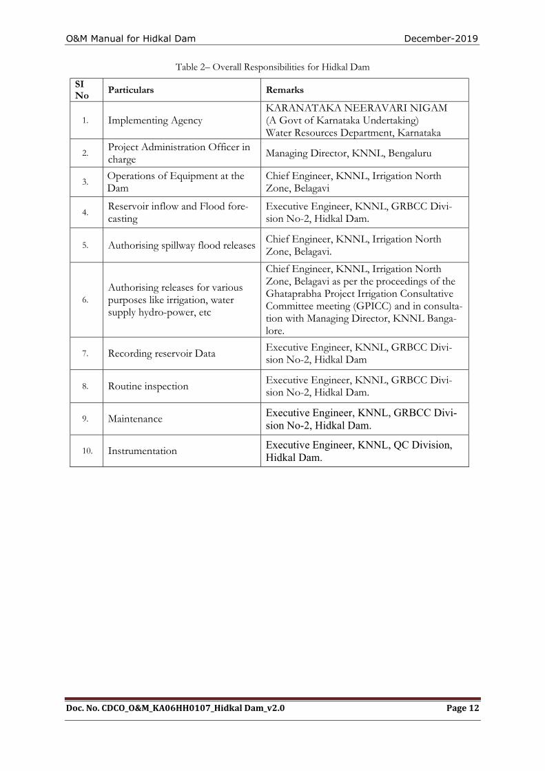
1.5 Assignment of Responsibility
The KARANATAKA NEERAVARI Nigam is the owner and has the final authority and responsibility for the operation and maintenance of the dam. Identification of all areas of responsibilities connected with the operation and maintenance of the dam are covered in this section. The officer’s responsibilities for the various functions are identified by their designation and, in particular, the responsibilities of operating personnel are specifically identified below which include regularly scheduled duties and which staff personnel are required to perform as outlined in the following tables:
O&M Manual for Hidkal Dam December-2019
Doc. No. CDCO_O&M_KA06HH0107_Hidkal Dam_v2.0 Page 12
Table 2– Overall Responsibilities for Hidkal Dam
SI No Particulars Remarks
1. Implementing Agency KARANATAKA NEERAVARI NIGAM (A Govt of Karnataka Undertaking) Water Resources Department, Karnataka
2. Project Administration Officer in charge Managing Director, KNNL, Bengaluru
3. Operations of Equipment at the Dam
Chief Engineer, KNNL, Irrigation North Zone, Belagavi
4. Reservoir inflow and Flood fore-casting
Executive Engineer, KNNL, GRBCC Divi-sion No-2, Hidkal Dam.
5. Authorising spillway flood releases Chief Engineer, KNNL, Irrigation North Zone, Belagavi.
6. Authorising releases for various purposes like irrigation, water supply hydro-power, etc
Chief Engineer, KNNL, Irrigation North Zone, Belagavi as per the proceedings of the Ghataprabha Project Irrigation Consultative Committee meeting (GPICC) and in consulta-tion with Managing Director, KNNL Banga-lore.
7. Recording reservoir Data Executive Engineer, KNNL, GRBCC Divi-sion No-2, Hidkal Dam
8. Routine inspection Executive Engineer, KNNL, GRBCC Divi-sion No-2, Hidkal Dam.
9. Maintenance Executive Engineer, KNNL, GRBCC Divi-sion No-2, Hidkal Dam.
10. Instrumentation Executive Engineer, KNNL, QC Division, Hidkal Dam.
O&M Manual for Hidkal Dam December-2019
Doc. No. CDCO_O&M_KA06HH0107_Hidkal Dam_v2.0 Page 13
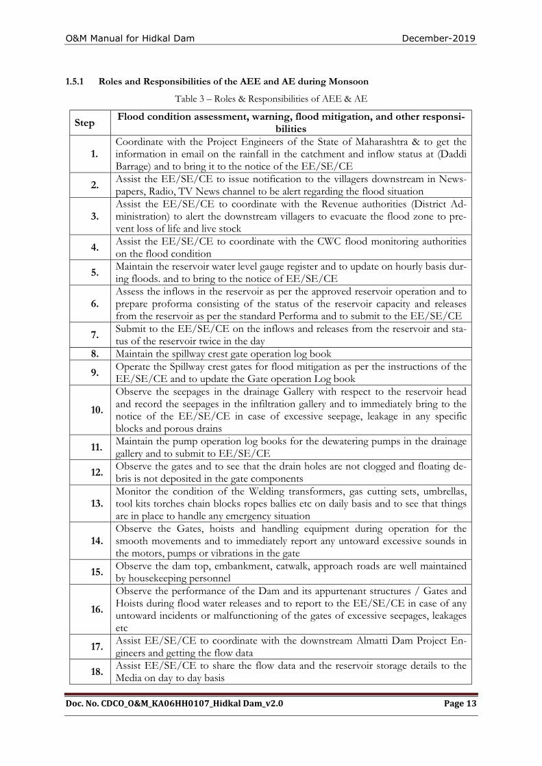
1.5.1 Roles and Responsibilities of the AEE and AE during Monsoon
Table 3 – Roles & Responsibilities of AEE & AE
Step Flood condition assessment, warning, flood mitigation, and other responsi-
bilities
1. Coordinate with the Project Engineers of the State of Maharashtra & to get the information in email on the rainfall in the catchment and inflow status at (Daddi Barrage) and to bring it to the notice of the EE/SE/CE
2. Assist the EE/SE/CE to issue notification to the villagers downstream in News-papers, Radio, TV News channel to be alert regarding the flood situation
3. Assist the EE/SE/CE to coordinate with the Revenue authorities (District Ad-ministration) to alert the downstream villagers to evacuate the flood zone to pre-vent loss of life and live stock
4. Assist the EE/SE/CE to coordinate with the CWC flood monitoring authorities on the flood condition
5. Maintain the reservoir water level gauge register and to update on hourly basis dur-ing floods. and to bring to the notice of EE/SE/CE
6. Assess the inflows in the reservoir as per the approved reservoir operation and to prepare proforma consisting of the status of the reservoir capacity and releases from the reservoir as per the standard Performa and to submit to the EE/SE/CE
7. Submit to the EE/SE/CE on the inflows and releases from the reservoir and sta-tus of the reservoir twice in the day
8. Maintain the spillway crest gate operation log book
9. Operate the Spillway crest gates for flood mitigation as per the instructions of the EE/SE/CE and to update the Gate operation Log book
10.
Observe the seepages in the drainage Gallery with respect to the reservoir head and record the seepages in the infiltration gallery and to immediately bring to the notice of the EE/SE/CE in case of excessive seepage, leakage in any specific blocks and porous drains
11. Maintain the pump operation log books for the dewatering pumps in the drainage gallery and to submit to EE/SE/CE
12. Observe the gates and to see that the drain holes are not clogged and floating de-bris is not deposited in the gate components
13. Monitor the condition of the Welding transformers, gas cutting sets, umbrellas, tool kits torches chain blocks ropes ballies etc on daily basis and to see that things are in place to handle any emergency situation
14. Observe the Gates, hoists and handling equipment during operation for the smooth movements and to immediately report any untoward excessive sounds in the motors, pumps or vibrations in the gate
15. Observe the dam top, embankment, catwalk, approach roads are well maintained by housekeeping personnel
16.
Observe the performance of the Dam and its appurtenant structures / Gates and Hoists during flood water releases and to report to the EE/SE/CE in case of any untoward incidents or malfunctioning of the gates of excessive seepages, leakages etc
17. Assist EE/SE/CE to coordinate with the downstream Almatti Dam Project En-gineers and getting the flow data
18. Assist EE/SE/CE to share the flow data and the reservoir storage details to the Media on day to day basis
O&M Manual for Hidkal Dam December-2019
Doc. No. CDCO_O&M_KA06HH0107_Hidkal Dam_v2.0 Page 14
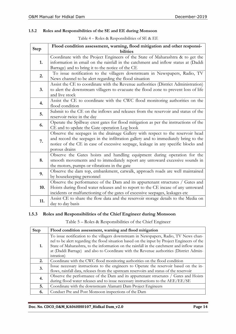
1.5.2 Roles and Responsibilities of the SE and EE during Monsoon
Table 4 – Roles & Responsibilities of SE & EE
Step Flood condition assessment, warning, flood mitigation and other responsi-
bilities
1. Coordinate with the Project Engineers of the State of Maharashtra & to get the information in email on the rainfall in the catchment and inflow status at (Daddi Barrage) and to bring it to the notice of the CE
2. To issue notification to the villagers downstream in Newspapers, Radio, TV News channel to be alert regarding the flood situation
3. Assist the CE to coordinate with the Revenue authorities (District Administration) to alert the downstream villagers to evacuate the flood zone to prevent loss of life and live stock
4. Assist the CE to coordinate with the CWC flood monitoring authorities on the flood condition
5. Submit to the CE on the inflows and releases from the reservoir and status of the reservoir twice in the day
6. Operate the Spillway crest gates for flood mitigation as per the instructions of the CE and to update the Gate operation Log book
7.
Observe the seepages in the drainage Gallery with respect to the reservoir head and record the seepages in the infiltration gallery and to immediately bring to the notice of the CE in case of excessive seepage, leakage in any specific blocks and porous drains
8. Observe the Gates hoists and handling equipment during operation for the smooth movements and to immediately report any untoward excessive sounds in the motors, pumps or vibrations in the gate
9. Observe the dam top, embankment, catwalk, approach roads are well maintained by housekeeping personnel
10. Observe the performance of the Dam and its appurtenant structures / Gates and Hoists during flood water releases and to report to the CE incase of any untoward incidents or malfunctioning of the gates of excessive seepages, leakages etc
11. Assist CE to share the flow data and the reservoir storage details to the Media on day to day basis
1.5.3 Roles and Responsibilities of the Chief Engineer during Monsoon
Table 5 – Roles & Responsibilities of the Chief Engineer
Step Flood condition assessment, warning and flood mitigation
1.
To issue notification to the villagers downstream in Newspapers, Radio, TV News chan-nel to be alert regarding the flood situation based on the input by Project Engineers of the State of Maharashtra, to the information on the rainfall in the catchment and inflow status at (Daddi Barrage) and also to Coordinate with the Revenue authorities (District Admin-istration)
2. Coordinate with the CWC flood monitoring authorities on the flood condition
3. Issue necessary instructions to the engineers to Operate the reservoir based on the in-flows, rainfall data, releases from the upstream reservoirs and status of the reservoir
4. Observe the performance of the Dam and its appurtenant structures / Gates and Hoists during flood water releases and to issue necessary instructions to the AEE/EE/SE
5. Coordinate with the downstream Alamatti Dam Project Engineers 6. Conduct Pre and Post Monsoon inspections of the Dam
O&M Manual for Hidkal Dam December-2019
Doc. No. CDCO_O&M_KA06HH0107_Hidkal Dam_v2.0 Page 15
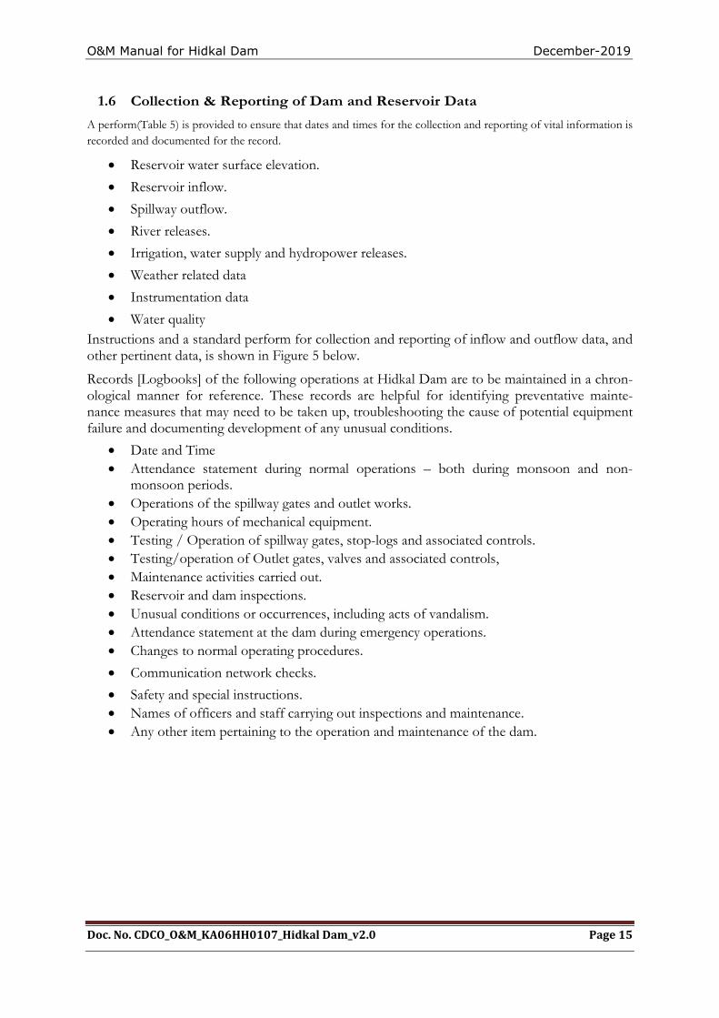
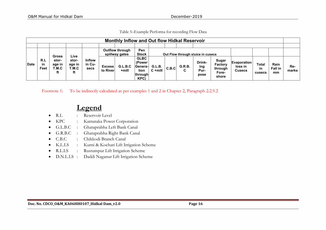
1.6 Collection & Reporting of Dam and Reservoir Data
A perform(Table 5) is provided to ensure that dates and times for the collection and reporting of vital information is recorded and documented for the record.
Reservoir water surface elevation.
Reservoir inflow.
Spillway outflow.
River releases.
Irrigation, water supply and hydropower releases.
Weather related data
Instrumentation data
Water quality Instructions and a standard perform for collection and reporting of inflow and outflow data, and other pertinent data, is shown in Figure 5 below.
Records [Logbooks] of the following operations at Hidkal Dam are to be maintained in a chron-ological manner for reference. These records are helpful for identifying preventative mainte-nance measures that may need to be taken up, troubleshooting the cause of potential equipment failure and documenting development of any unusual conditions.
Date and Time Attendance statement during normal operations – both during monsoon and non-
monsoon periods. Operations of the spillway gates and outlet works. Operating hours of mechanical equipment. Testing / Operation of spillway gates, stop-logs and associated controls. Testing/operation of Outlet gates, valves and associated controls, Maintenance activities carried out. Reservoir and dam inspections. Unusual conditions or occurrences, including acts of vandalism. Attendance statement at the dam during emergency operations. Changes to normal operating procedures.
Communication network checks.
Safety and special instructions. Names of officers and staff carrying out inspections and maintenance. Any other item pertaining to the operation and maintenance of the dam.
O&M Manual for Hidkal Dam December-2019
Doc. No. CDCO_O&M_KA06HH0107_Hidkal Dam_v2.0 Page 16
Table 5–Example Performa for recording Flow Data
Footnote 1: To be indirectly calculated as per examples 1 and 2 in Chapter 2, Paragraph 2.2.9.2
Legend R.L : Reservoir Level KPC : Karnataka Power Corporation G.L.B.C : Ghataprabha Left Bank Canal G.R.B.C : Ghataprabha Right Bank Canal C.B.C : Chikkodi Branch Canal K.L.I.S : Kurni & Kochari Lift Irrigation Scheme R.L.I.S : Rustumpur Lift Irrigation Scheme D.N.L.I.S : Daddi Naganur Lift Irrigation Scheme
Monthly Inflow and Out flow Hidkal Reservoir
Date R.L in
Feet
Gross stor-
age in T.M.C
ft
Live stor-
age in T.M.C
ft
Inflow in Cu-secs
Outflow through spillway gates
Pen Stock Out Flow through sluice in cusecs
Excess to River
G.L.B.C +mill
GLBC (Power Genera-
tion through
KPC)
G.L.B.C +mill
C.B.C G.R.B.
C
Drink-ing Pur-pose
Sugar Factory through
Fore-shore
(Evaporation loss in Cusecs
Total in
cusecs
Rain Fall in
mm
Re-marks
O&M Manual for Hidkal Dam December-2019
Doc. No. CDCO_O&M_KA06HH0107_Hidkal Dam_v2.0 Page 17
1.7 Public and Project Staff - Health and Safety
As safety of Project Staff is of prime concern, safety instructions & protection measures at the dam are carried out by all staff / project personnel. Electronic kiosks located on the left and right abutment provide public notices of events and status of security of the dam and downstream river conditions.
1.7.1 Restricted Areas
Certain areas of the dam and reservoir are restricted for entry of the general public. The purpose of restrictions is for security of the dam, public safety and uninterrupted safe operation of the dam.
Restricted areas will include the following:
Confined spaces such as adits, galleries, etc.
Spillway approach areas, chutes and stilling basins
Dam upstream and downstream slopes/faces
Control buildings and valve areas.
Intake or outlet channels adjacent to hydraulic structures.
1.7.2 Details of the Security arrangements at Hidkal Dam Site.
The security arrangements of Hidkal Dam are entrusted to the private security personal on ten-der basis with a total strength of 36 for 24hrs Security personnel and 3 security supervisors are deployed.
O&M Manual for Hidkal Dam December-2019
Doc. No. CDCO_O&M_KA06HH0107_Hidkal Dam_v2.0 Page 18
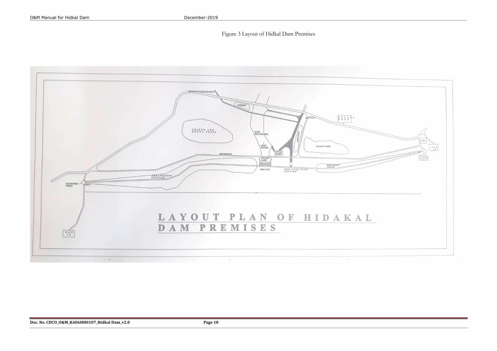
Figure 3 Layout of Hidkal Dam Premises

O&M Manual for Hidkal Dam December-2019
Doc. No. CDCO_O&M_KA06HH0107_Hidkal Dam_v2.0 Page 19
THIS PAGE LEFT BLANK INTENTIONALLY
O&M Manual for Hidkal Dam December-2019
Doc. No. CDCO_O&M_KA06HH0107_Hidkal Dam_v2.0 Page 20
1.8 Staff Position, Communication & Warning System
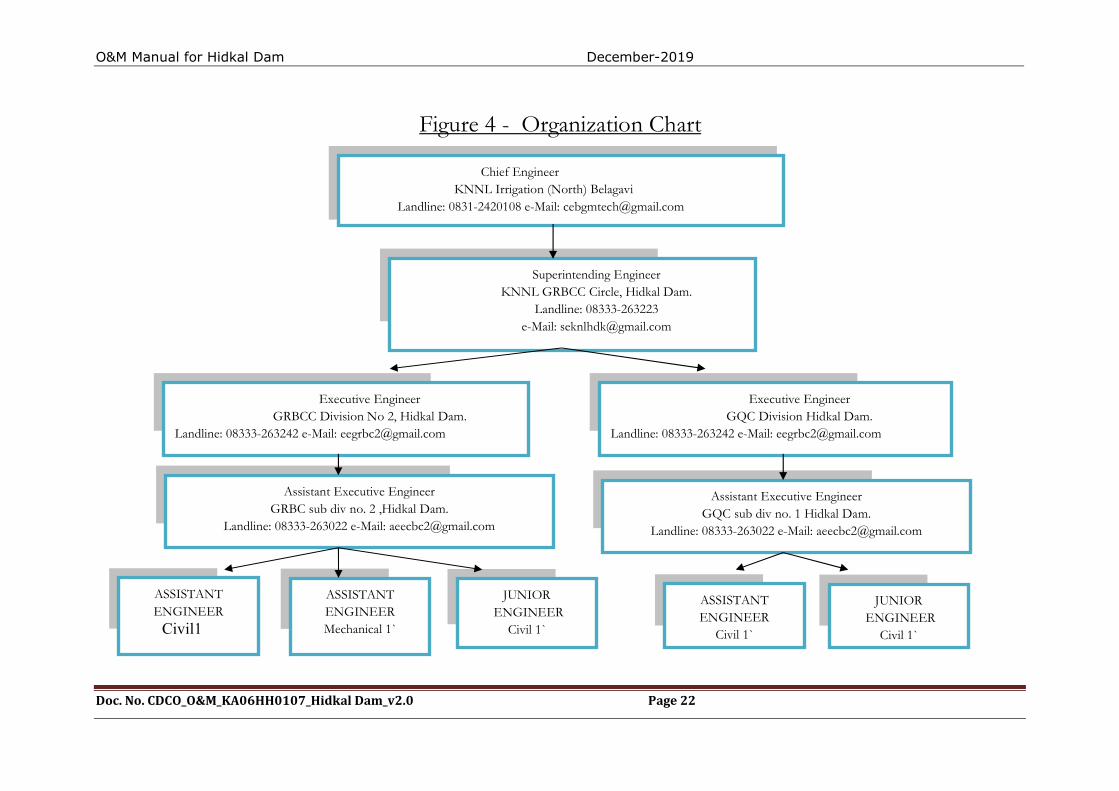
The number & description of operating unit personnel posted/placed at different locations of the dam are noted and referenced in this Manual. Staff positions vary according to requirement during monsoon / non-monsoon periods. An engineering organizational chart is shown in Figure 4below.
The means of communications both in normal and emergency situations are identified in the Communication Directory found below. Available communication means including mobile phones, at different locations on the dam.

O&M Manual for Hidkal Dam December-2019
Doc. No. CDCO_O&M_KA06HH0107_Hidkal Dam_v2.0 Page 21
THIS PAGE LEFT BLANK INTENTIONALLY
O&M Manual for Hidkal Dam December-2019
Doc. No. CDCO_O&M_KA06HH0107_Hidkal Dam_v2.0 Page 22
Assistant Executive Engineer
Figure 4 - Organization Chart
Chief Engineer KNNL Irrigation (North) Belagavi Landline: 0831-2420108 e-Mail: [email protected]
Superintending Engineer KNNL GRBCC Circle, Hidkal Dam.
Landline: 08333-263223 e-Mail: [email protected]
Executive Engineer GRBCC Division No 2, Hidkal Dam.
Landline: 08333-263242 e-Mail: [email protected]
Executive Engineer GQC Division Hidkal Dam.
Landline: 08333-263242 e-Mail: [email protected]
Assistant Executive Engineer GRBC sub div no. 2 ,Hidkal Dam.
Landline: 08333-263022 e-Mail: [email protected]
Assistant Executive Engineer GQC sub div no. 1 Hidkal Dam.
Landline: 08333-263022 e-Mail: [email protected]
ASSISTANT ENGINEER
Civil1
Civil 1`
ASSISTANT ENGINEER Mechanical 1`
JUNIOR ENGINEER
Civil 1`
ASSISTANT ENGINEER
Civil 1`
JUNIOR ENGINEER
Civil 1`
O&M Manual for Hidkal Dam December-2019
Doc. No. CDCO_O&M_KA06HH0107_Hidkal Dam_v2.0 Page 23
1.8.1 Schedule of General Duties for Project Engineers
Schedules of duties being performed by the staff assigned to various locations and components of and site registers.
DAILY
Visual inspection of dam
Crest of dam (Dam top)
Upstream and downstream faces
Visible portions of foundation and abutments contacts
Galleries
Record water surface elevation. (during monsoon on hourly basis)
Record reservoir inflow and spillway discharge. (during monsoon on hourly basis)
Record releases from outlets /sluices.
Record seepage from drainage systems-Toe drains, Gallery drains etc. on daily basis Record meteorological data.
Check security and safety devices.
Complete logbook / site registers which should include the above information
WEEKLY
Electrical System
Standby generator (DG Sets)
Run for 15-30 min to achieve recommended operating temperature
Check status of batteries and keep them charged.
Check Fuel Supply
Drainage systems - Toe drains, Gallery drains etc., and, during any reservoir filling operations
MONTHLY
Check condition of:
Dam and Reservoir
Reservoir periphery (During Monsoon)
Drainage systems - Toe Drains, Gallery drains etc. (on regular basis)
Measuring devices/Instruments
Security and safety devices – rectification, if needed.
Communication Devices
Status of Vegetation growth
Check Sign/Warning display boards near vulnerable locations are in place and updated as necessary
Mechanical/Electrical System
O&M Manual for Hidkal Dam December-2019
Doc. No. CDCO_O&M_KA06HH0107_Hidkal Dam_v2.0 Page 24
Replace fuses/light bulbs, as necessary
Inspect and maintain ventilation system; check for and remove any obstructions
Cleaning of control panel boards
QUARTERLY
Outlet Works
Availability of updated operating instruction
Check gate air vents
Clean gate control switchboxes
Check operation of gates and valves
Grease gate hanger / dogging arrangements
Check
Check condition of trash rack of intake structure
Check condition of Outlet works &the Energy Dissipation Arrangement (EDA)
Spillway
Check for debris in inlet channel
Check operation of gates
Check for damages in spillway glacis, EDA, d/s area, etc.
Check and clear spillway bridge drains
Clean inside of motor control cabinet and remove debris, insect (bee nests), nests, rodents and bird nests.
Seals and seal seating shall be inspected for leakages.
Remove all dirt, girt etc. from trunnion assembly and lubricate trunnion bearing of the gab with suitable grease.
Other works
Check for adherence to instrumentation schedule
Record pertinent information in Operation Log
Check conditions of V-notch weirs/other seepage measuring devices
BI-ANNUAL
Spillway & outlet works
Check paint on gates and other areas of corrosion
Check lubrication of wire ropes and application of cardium compound.
Check mechanical hoist bearings and flexible coupling bearings
Check gear systems
Exercise gate and valves for operational efficiency
Check oil reservoir level in hydraulic system and top up as necessary
O&M Manual for Hidkal Dam December-2019
Doc. No. CDCO_O&M_KA06HH0107_Hidkal Dam_v2.0 Page 25
Check pressure release valve and clean any debris, dirt, other foreign objects as necessary
Lubricate gate rollers
Check rubber seals and seal clamp bar
Electrical System and Equipment
Change oil in stand by generator
Check exposed electrical wiring of :
Operating equipment of gates/hoists of Outlet works.
Operating equipment of gates and hoists of Spillway
Operating equipment of any other gates and hoists in dam
Spillway catwalk / bridge
Dam Gallery
Check Gate limit switches and adjust.
ANNUAL
Spillway &Outlet works
Paint
Metalwork, Gate, Hoists and all exposed metal parts for corrosion
Hydraulic power pack system
Exercise Gates
Examine stilling basin / energy dissipation arrangement and d/s channel & carry out rectification works, as necessary.
Check metal welds for damages/cracks in Gates, Hoist platform, Radial Gate Tie flats, Trunnion Girders/supports etc.
Electrical
Check electrical conduits, pull-boxes and switches for:
Outlet works valve house
Gates & hoists
Spillway bridge
Gallery
FIVE YEAR (PERIODIC)
Inspect intake structures, trash racks and stilling basin / energy dissipation arrangement, which normally are underwater; less frequent if experience indicates. This may need to be done by carrying out dewatering or by divers/remote operated vehicle (ROV) as necessary.
Review Dam operation procedures and EAP and update as necessary.
O&M Manual for Hidkal Dam December-2019
Doc. No. CDCO_O&M_KA06HH0107_Hidkal Dam_v2.0 Page 26
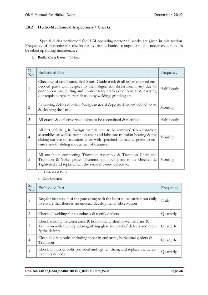
1.8.2 Hydro-Mechanical Inspections / Checks
Special duties performed for H-M operating personnel works are given in this section. Frequency of inspections / checks for hydro-mechanical components and necessary actions to be taken up during maintenance
1. Radial Crest Gates - 10 Nos.
a. Embedded Parts
b. Gate Structure
Sl. No. Embedded Part Frequency
1 Regular inspection of the gate along with the hoist to be carried out daily to ensure that there is no unusual development/ observation Daily
2 Check all welding for soundness & rectify defects Quarterly
3 Check welding between arms & horizontal girders as well as arms & Trunnion with the help of magnifying glass for cracks/ defects and recti-fy the defects.
Quarterly
4 Clean all drain boles including those in end arms, horizontal girders & Trunnion
Quarterly
5 Check all nuts & bolts provided and tighten them, and replace the defec-tive nuts & bolts Quarterly
Sl. No. Embedded Part Frequency
1
Checking of seal beams. Seal Seats, Guide track & all other exposed em-bedded parts with respect to their alignment, distortion: if any due to continuous use, pitting and un-necessary cracks due to wear & carrying out requisite repairs, rectification by welding, grinding etc.
Half Yearly
2 Removing debris & other foreign material deposited on embedded parts & cleaning the same Monthly
3 All cracks & defective weld joints to be ascertained & rectified. Half Yearly
4
All dirt, debris, grit, foreign material etc. to be removed from trunnion assemblies as well as trunnion chair and lubricate trunnion bearing & the sliding surface on trunnion chair with specified lubricant/ grade to en-sure smooth sliding movement of trunnion.
Monthly
5 All nut bolts connecting Trunnion Assembly & Trunnion Chair and Trunnion & Yoke, girder Trunnion pin lock plate to be checked & Tightened and replacement the same if found defective.
Monthly
O&M Manual for Hidkal Dam December-2019
Doc. No. CDCO_O&M_KA06HH0107_Hidkal Dam_v2.0 Page 27
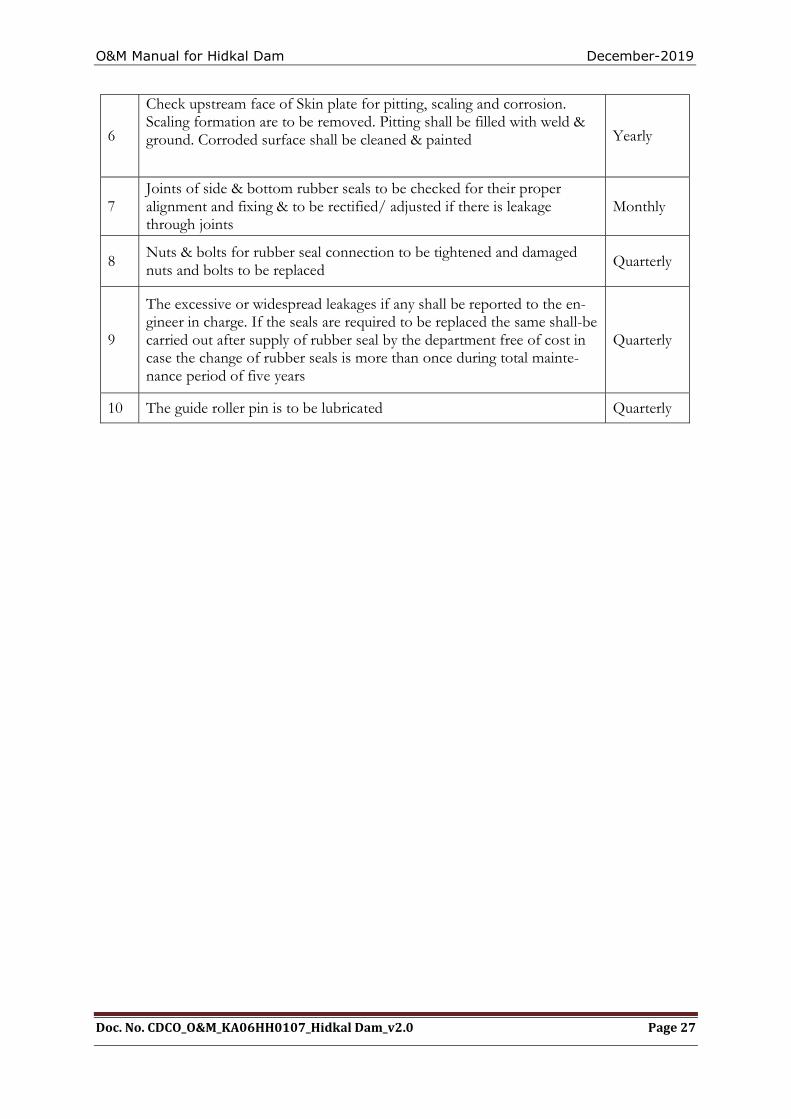
6
Check upstream face of Skin plate for pitting, scaling and corrosion. Scaling formation are to be removed. Pitting shall be filled with weld & ground. Corroded surface shall be cleaned & painted Yearly
7 Joints of side & bottom rubber seals to be checked for their proper alignment and fixing & to be rectified/ adjusted if there is leakage through joints
Monthly
8 Nuts & bolts for rubber seal connection to be tightened and damaged nuts and bolts to be replaced Quarterly
9
The excessive or widespread leakages if any shall be reported to the en-gineer in charge. If the seals are required to be replaced the same shall-be carried out after supply of rubber seal by the department free of cost in case the change of rubber seals is more than once during total mainte-nance period of five years
Quarterly
10 The guide roller pin is to be lubricated Quarterly
O&M Manual for Hidkal Dam December-2019
Doc. No. CDCO_O&M_KA06HH0107_Hidkal Dam_v2.0 Page 28
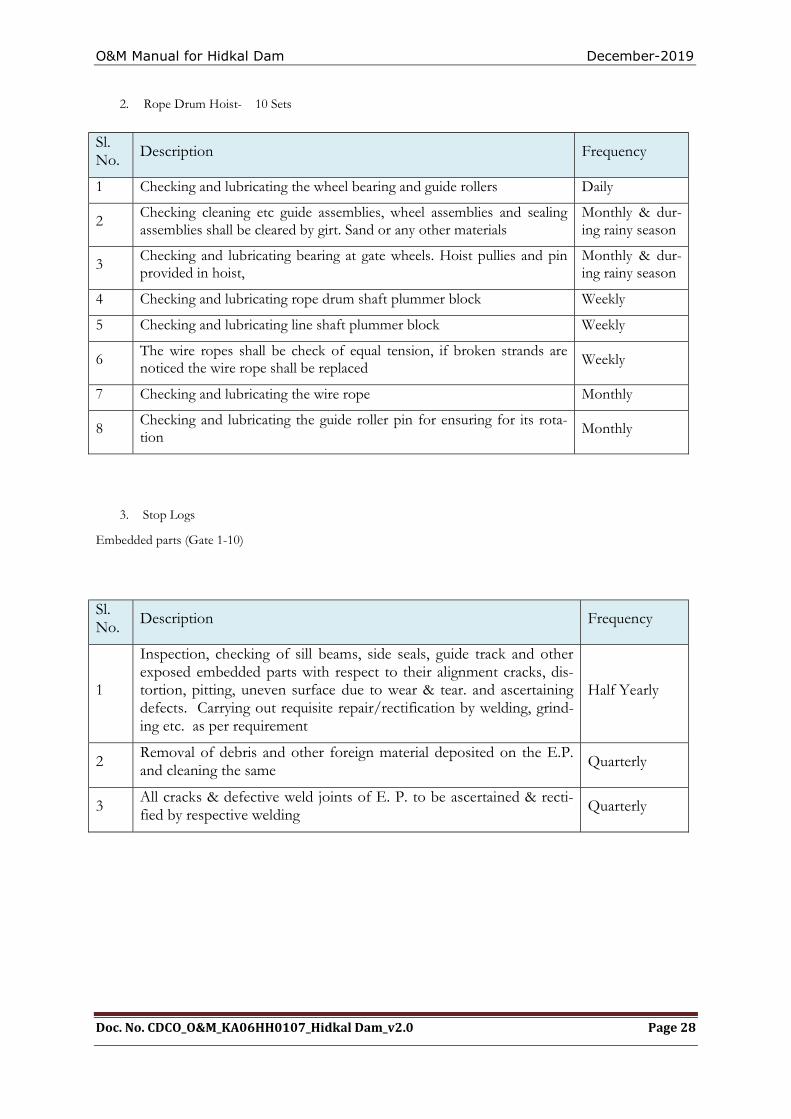
2. Rope Drum Hoist- 10 Sets
3. Stop Logs
Embedded parts (Gate 1-10)
Sl. No. Description Frequency
1 Checking and lubricating the wheel bearing and guide rollers Daily
2 Checking cleaning etc guide assemblies, wheel assemblies and sealing assemblies shall be cleared by girt. Sand or any other materials
Monthly & dur-ing rainy season
3 Checking and lubricating bearing at gate wheels. Hoist pullies and pin provided in hoist,
Monthly & dur-ing rainy season
4 Checking and lubricating rope drum shaft plummer block Weekly
5 Checking and lubricating line shaft plummer block Weekly
6 The wire ropes shall be check of equal tension, if broken strands are noticed the wire rope shall be replaced
Weekly
7 Checking and lubricating the wire rope Monthly
8 Checking and lubricating the guide roller pin for ensuring for its rota-tion
Monthly
Sl. No. Description Frequency
1
Inspection, checking of sill beams, side seals, guide track and other exposed embedded parts with respect to their alignment cracks, dis-tortion, pitting, uneven surface due to wear & tear. and ascertaining defects. Carrying out requisite repair/rectification by welding, grind-ing etc. as per requirement
Half Yearly
2 Removal of debris and other foreign material deposited on the E.P. and cleaning the same Quarterly
3 All cracks & defective weld joints of E. P. to be ascertained & recti-fied by respective welding Quarterly
O&M Manual for Hidkal Dam December-2019
Doc. No. CDCO_O&M_KA06HH0107_Hidkal Dam_v2.0 Page 29
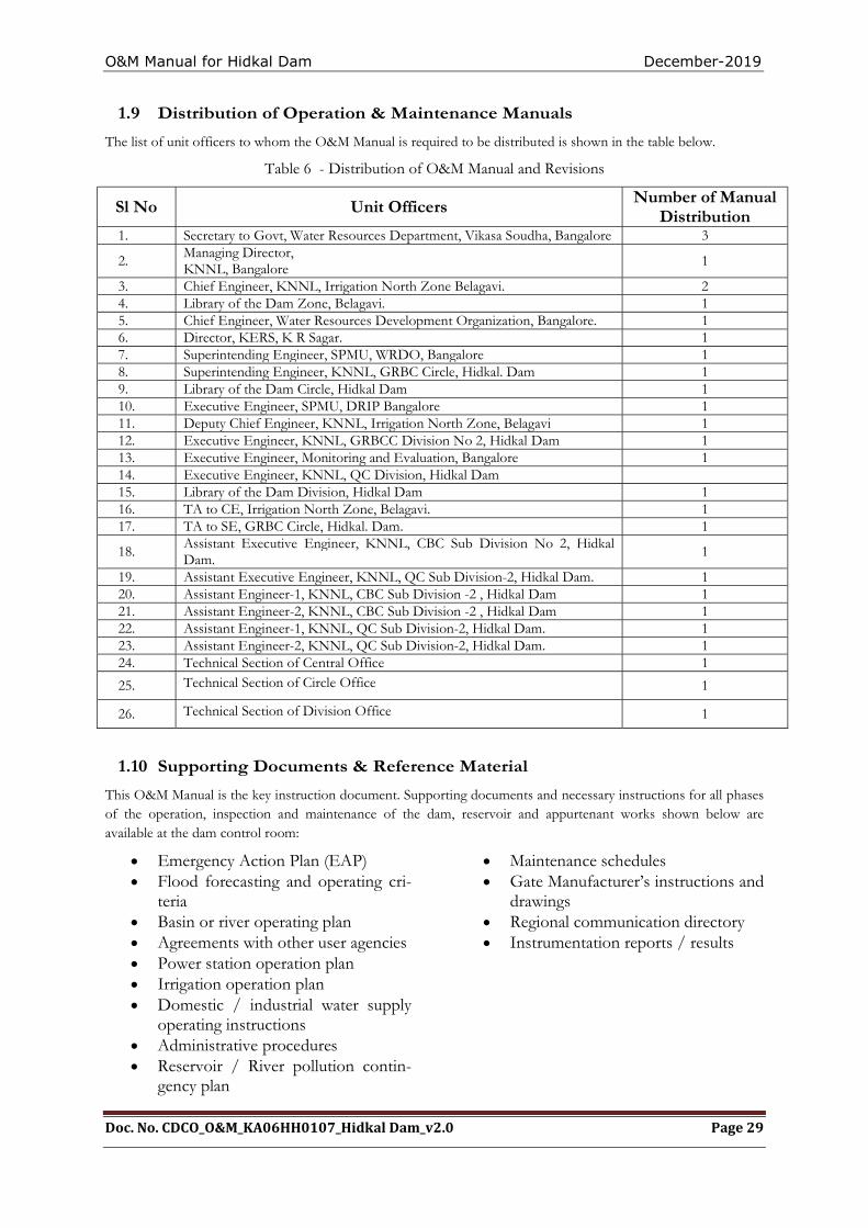
1.9 Distribution of Operation & Maintenance Manuals
The list of unit officers to whom the O&M Manual is required to be distributed is shown in the table below.
Table 6 - Distribution of O&M Manual and Revisions
Sl No Unit Officers Number of Manual Distribution
1. Secretary to Govt, Water Resources Department, Vikasa Soudha, Bangalore 3
2. Managing Director, KNNL, Bangalore
1
3. Chief Engineer, KNNL, Irrigation North Zone Belagavi. 2 4. Library of the Dam Zone, Belagavi. 1 5. Chief Engineer, Water Resources Development Organization, Bangalore. 1 6. Director, KERS, K R Sagar. 1 7. Superintending Engineer, SPMU, WRDO, Bangalore 1 8. Superintending Engineer, KNNL, GRBC Circle, Hidkal. Dam 1 9. Library of the Dam Circle, Hidkal Dam 1 10. Executive Engineer, SPMU, DRIP Bangalore 1 11. Deputy Chief Engineer, KNNL, Irrigation North Zone, Belagavi 1 12. Executive Engineer, KNNL, GRBCC Division No 2, Hidkal Dam 1 13. Executive Engineer, Monitoring and Evaluation, Bangalore 1 14. Executive Engineer, KNNL, QC Division, Hidkal Dam 15. Library of the Dam Division, Hidkal Dam 1 16. TA to CE, Irrigation North Zone, Belagavi. 1 17. TA to SE, GRBC Circle, Hidkal. Dam. 1
18. Assistant Executive Engineer, KNNL, CBC Sub Division No 2, Hidkal Dam.
1
19. Assistant Executive Engineer, KNNL, QC Sub Division-2, Hidkal Dam. 1 20. Assistant Engineer-1, KNNL, CBC Sub Division -2 , Hidkal Dam 1 21. Assistant Engineer-2, KNNL, CBC Sub Division -2 , Hidkal Dam 1 22. Assistant Engineer-1, KNNL, QC Sub Division-2, Hidkal Dam. 1 23. Assistant Engineer-2, KNNL, QC Sub Division-2, Hidkal Dam. 1 24. Technical Section of Central Office 1
25. Technical Section of Circle Office 1
26. Technical Section of Division Office 1
1.10 Supporting Documents & Reference Material
This O&M Manual is the key instruction document. Supporting documents and necessary instructions for all phases of the operation, inspection and maintenance of the dam, reservoir and appurtenant works shown below are available at the dam control room:
Emergency Action Plan (EAP) Flood forecasting and operating cri-
teria Basin or river operating plan Agreements with other user agencies Power station operation plan Irrigation operation plan Domestic / industrial water supply
operating instructions Administrative procedures Reservoir / River pollution contin-
gency plan
Maintenance schedules Gate Manufacturer’s instructions and
drawings Regional communication directory Instrumentation reports / results

O&M Manual for Hidkal Dam December-2019
Doc. No. CDCO_O&M_KA06HH0107_Hidkal Dam_v2.0 Page 30
THISPAGE LEFT BLANK INTENTIONALLY
O&M Manual for Hidkal Dam December-2019
Doc. No. CDSO_O&M_KA06HH107_Hidkal Dam_v2.0 Page 31
CHAPTER 2. PROJECT OPERATION
2.1 Basic Data
The Hidkal Dam operation plan consists of step-by-step instructions for operating the dam and reservoir during routine (normal) and emergency conditions. The operating procedures for normal operations are discussed in this chapter including operating criteria for the reservoir, spillway & outlets. The operation of a dam involves regulation of its reservoir as per project specific requirements. This includes the use of reservoir Operation Rule curve area capacity curve Spillway discharge rating curve, Sluice discharge rating curve and design flood; as described below.
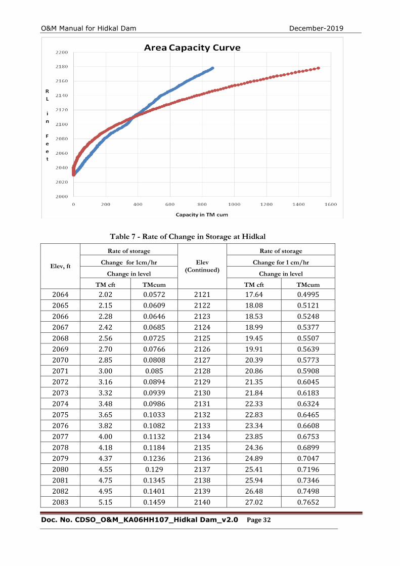
2.1.1 Area Capacity curves.
The area capacity curves for Hidkal Dam in tabular and graphical form are shown in Table 7 and Fig-ure 5
2.1.2 Data of the historic floods
Considering Ingle’s Formula, the maximum flood Discharges Q = 7000A/√A+4 =7000 x 545 /√545+4 =1,63,000 Cusecs A= Catchment area in Sq. miles Though the flood data is not available for the specific dam site, data for observed peak flood at Ha-dalaga on Ghataprabha river and at Rajagoli on tamraparani river are available. The figures are 47288 cusecs at Hadalaga and 33,126 cusecs at Rajagaoli, totaling to80414 cusecs. A mul,tiple factor of two is considered in this case to arrive the flood discharge of 1,60,828 cusecs. It was found that values ob-tained from Ingle’s formula from observed peak flood data as done above and unit hydrograph meth-od where more or less identical. In view of this fact the flood of 163000 cusecs is considered for de-sign of spillway.
O&M Manual for Hidkal Dam December-2019
Doc. No. CDSO_O&M_KA06HH107_Hidkal Dam_v2.0 Page 32
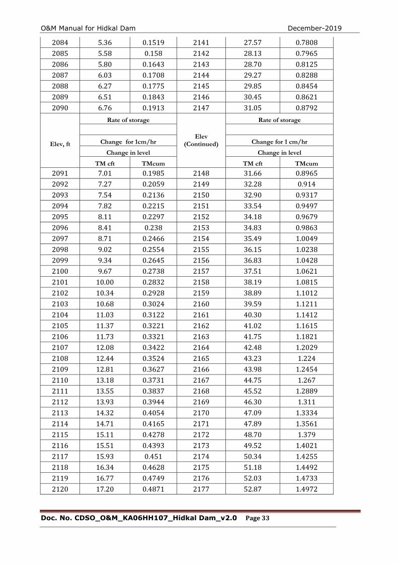
Table 7 - Rate of Change in Storage at Hidkal
Elev, ft
Rate of storage
Elev (Continued)
Rate of storage
Change for 1cm/hr Change for 1 cm/hr
Change in level Change in level
TM cft TMcum TM cft TMcum
2064 2.02 0.0572 2121 17.64 0.4995
2065 2.15 0.0609 2122 18.08 0.5121
2066 2.28 0.0646 2123 18.53 0.5248
2067 2.42 0.0685 2124 18.99 0.5377
2068 2.56 0.0725 2125 19.45 0.5507
2069 2.70 0.0766 2126 19.91 0.5639
2070 2.85 0.0808 2127 20.39 0.5773
2071 3.00 0.085 2128 20.86 0.5908
2072 3.16 0.0894 2129 21.35 0.6045
2073 3.32 0.0939 2130 21.84 0.6183
2074 3.48 0.0986 2131 22.33 0.6324
2075 3.65 0.1033 2132 22.83 0.6465
2076 3.82 0.1082 2133 23.34 0.6608
2077 4.00 0.1132 2134 23.85 0.6753
2078 4.18 0.1184 2135 24.36 0.6899
2079 4.37 0.1236 2136 24.89 0.7047
2080 4.55 0.129 2137 25.41 0.7196
2081 4.75 0.1345 2138 25.94 0.7346
2082 4.95 0.1401 2139 26.48 0.7498
2083 5.15 0.1459 2140 27.02 0.7652
O&M Manual for Hidkal Dam December-2019
Doc. No. CDSO_O&M_KA06HH107_Hidkal Dam_v2.0 Page 33
2084 5.36 0.1519 2141 27.57 0.7808
2085 5.58 0.158 2142 28.13 0.7965
2086 5.80 0.1643 2143 28.70 0.8125
2087 6.03 0.1708 2144 29.27 0.8288
2088 6.27 0.1775 2145 29.85 0.8454
2089 6.51 0.1843 2146 30.45 0.8621
2090 6.76 0.1913 2147 31.05 0.8792
Elev, ft
Rate of storage
Elev (Continued)
Rate of storage
Change for 1cm/hr Change for 1 cm/hr
Change in level Change in level
TM cft TMcum TM cft TMcum
2091 7.01 0.1985 2148 31.66 0.8965
2092 7.27 0.2059 2149 32.28 0.914
2093 7.54 0.2136 2150 32.90 0.9317
2094 7.82 0.2215 2151 33.54 0.9497
2095 8.11 0.2297 2152 34.18 0.9679
2096 8.41 0.238 2153 34.83 0.9863
2097 8.71 0.2466 2154 35.49 1.0049
2098 9.02 0.2554 2155 36.15 1.0238
2099 9.34 0.2645 2156 36.83 1.0428
2100 9.67 0.2738 2157 37.51 1.0621
2101 10.00 0.2832 2158 38.19 1.0815
2102 10.34 0.2928 2159 38.89 1.1012
2103 10.68 0.3024 2160 39.59 1.1211
2104 11.03 0.3122 2161 40.30 1.1412
2105 11.37 0.3221 2162 41.02 1.1615
2106 11.73 0.3321 2163 41.75 1.1821
2107 12.08 0.3422 2164 42.48 1.2029
2108 12.44 0.3524 2165 43.23 1.224
2109 12.81 0.3627 2166 43.98 1.2454
2110 13.18 0.3731 2167 44.75 1.267
2111 13.55 0.3837 2168 45.52 1.2889
2112 13.93 0.3944 2169 46.30 1.311
2113 14.32 0.4054 2170 47.09 1.3334
2114 14.71 0.4165 2171 47.89 1.3561
2115 15.11 0.4278 2172 48.70 1.379
2116 15.51 0.4393 2173 49.52 1.4021
2117 15.93 0.451 2174 50.34 1.4255
2118 16.34 0.4628 2175 51.18 1.4492
2119 16.77 0.4749 2176 52.03 1.4733
2120 17.20 0.4871 2177 52.87 1.4972
O&M Manual for Hidkal Dam December-2019
Doc. No. CDSO_O&M_KA06HH107_Hidkal Dam_v2.0 Page 34
2.1.2 Latest Design Flood and Features Related to Safety
The revised flood peaks of PMF under DRIP worked out in Case-I (1 Day PMP) and Case-II (2 day PMP) at Hidkal Dam as 7577 m^3/s and 6714.2m^3/s respectively and were approved by the Central water Commission New Delhi Vide Letter of the Director DSR Dte/Dir Hydrology(DSR) Dte.CWC Sewa Bhavan New Delhi CWC No.7/kar-64/2010-Hyd(S)/56-58 dated 17-02-2015. By using these PMF values flood routing of Hidkal reservoir was conducted by Karnataka Engineering Research station Krishna Raja Sagar to find out the adequacy of the Spillway. The flood routing study carried out by CPMU revealed that the revised MWL is at EL 663.46 m for the 1-day PMP flood. The TBL is for embankment dam section is at EL 668.1 m and for masonry dam section is at 666.0 m. The available freeboard above the 663.46 m MWL are, therefore, 4.64 m for embankment section and 2.54 m for masonry section, which are more than the minimum recom-mended 1.50 m as per IS 10635 and 1.0 m as per IS 6512, respectively.
2.2 Flood Management at Hidkal Reservoirs
2.2.1 Gate Operations:
The Gate Operation for flood management and Gate operation schedule during normal conditions are prepared by the design wing of Chief Engineer Irrigation North Belagavi. The same is adopted for operation the Gates of Hidkal Dam.
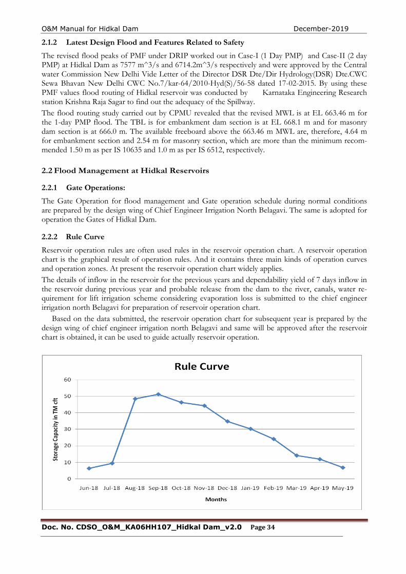
2.2.2 Rule Curve
Reservoir operation rules are often used rules in the reservoir operation chart. A reservoir operation chart is the graphical result of operation rules. And it contains three main kinds of operation curves and operation zones. At present the reservoir operation chart widely applies. The details of inflow in the reservoir for the previous years and dependability yield of 7 days inflow in the reservoir during previous year and probable release from the dam to the river, canals, water re-quirement for lift irrigation scheme considering evaporation loss is submitted to the chief engineer irrigation north Belagavi for preparation of reservoir operation chart. Based on the data submitted, the reservoir operation chart for subsequent year is prepared by the design wing of chief engineer irrigation north Belagavi and same will be approved after the reservoir chart is obtained, it can be used to guide actually reservoir operation.
O&M Manual for Hidkal Dam December-2019
Doc. No. CDSO_O&M_KA06HH107_Hidkal Dam_v2.0 Page 35
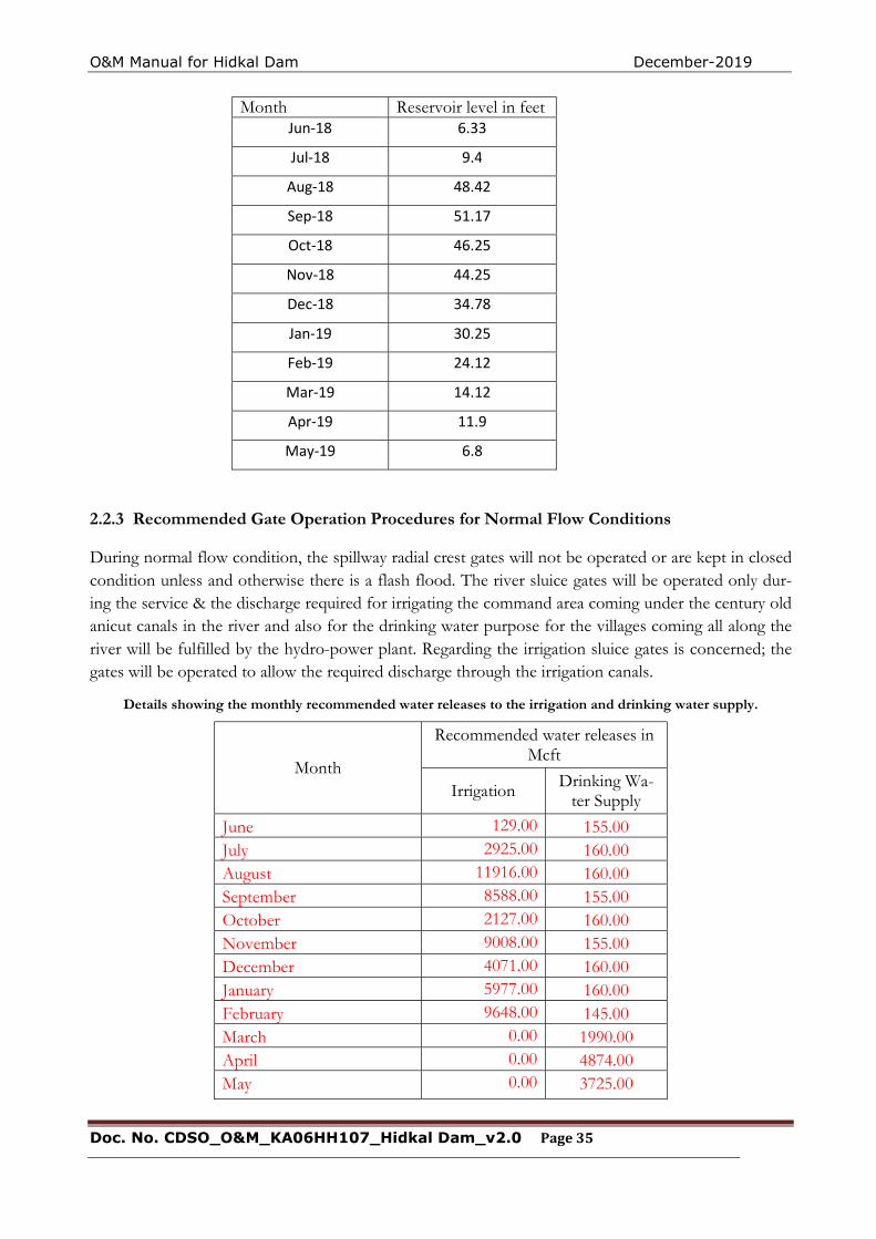
2.2.3 Recommended Gate Operation Procedures for Normal Flow Conditions
During normal flow condition, the spillway radial crest gates will not be operated or are kept in closed condition unless and otherwise there is a flash flood. The river sluice gates will be operated only dur-ing the service & the discharge required for irrigating the command area coming under the century old anicut canals in the river and also for the drinking water purpose for the villages coming all along the river will be fulfilled by the hydro-power plant. Regarding the irrigation sluice gates is concerned; the gates will be operated to allow the required discharge through the irrigation canals.
Details showing the monthly recommended water releases to the irrigation and drinking water supply.
Month
Recommended water releases in Mcft
Irrigation Drinking Wa-ter Supply
June 129.00 155.00 July 2925.00 160.00 August 11916.00 160.00 September 8588.00 155.00 October 2127.00 160.00 November 9008.00 155.00 December 4071.00 160.00 January 5977.00 160.00 February 9648.00 145.00 March 0.00 1990.00 April 0.00 4874.00 May 0.00 3725.00
Month Reservoir level in feet Jun-18 6.33
Jul-18 9.4
Aug-18 48.42
Sep-18 51.17
Oct-18 46.25
Nov-18 44.25
Dec-18 34.78
Jan-19 30.25
Feb-19 24.12
Mar-19 14.12
Apr-19 11.9
May-19 6.8
O&M Manual for Hidkal Dam December-2019
Doc. No. CDSO_O&M_KA06HH107_Hidkal Dam_v2.0 Page 36
2.2.4 Sequence of Opening or Closing of Gates.
Of the 10 crest gates, it is recommended that all 10 gates be operated for releasing water over the spillway. The gates are numbered 1 to 10. If, even when water is being released through the turbines at full capacity, the reservoir level tends to rise above 662.95m (FRL) ,the crest gates should be opened, starting With the end gates first (i.e., gate No.1 and 10), then the gates at the center (gates 5 and 6). And then the remaining gates in a systematic manner, such that no gate· is opened more than 0.2m. If the release over the spillway is to be further increased, the gates are opened further in a similar manner, no gate opening being more than 0. 2m. Further opening of gates, if required is done in the same way, keeping the difference in the openings of any two adjacent gates not more than 0.2m. During the recession part of the inflow hydrograph, it may be necessary to close the crest gates in or-der to maintain the reservoir level at the reservoir operation chart. In such a case, the closure of the gates should be done in the reverse order; the gate opened last being closed first, the entire opera-tion being such that the difference between the adjacent gate openings never exceed 0.2-m.
2.2.5 Inflow Forecasting
The gross storage of Hidkal Dam at FRL 662.95 m is 51.00 TMC. The Hidkal Dam has been de-signed for a probable maximum flood (PMF) of 4615.60 cumecs (1.63 lakhs cusecs) respectively. The storage in Hidkal Dam has commenced in the year 1977. During monsoon, incident rains in the catchment area cause the flash floods in Ghataprabha river. These floods may lead to problems like people getting displaced from their homes, huge damage to crops and other assets. The floods can have disastrous impact on the environment also. Adequate measures are required to be taken up in advance to control and regulate the flow water in the river. The regulation of flood water released from the Dams in Maharashtra is very important and has a most impact in Karnataka. The following measures are essential for effective management of floods in Ghataprabha River during the monsoons.
1) Nomination of liaising officers for respective reservoirs. 2) Sharing of Sub-basin wise directory of concerned officers responsible for flood management. 3) Exchange of data regarding rainfall, releases from dams, reservoir water levels.
Reservoir operation schedules.
Flood warning system in catchment area:
The regulation of flood from the dams on upstream of Hidkal reservoir is very crucial to quantify the inflow of floods into Hidkal dam. The agencies of Central water Commission will be coordinated to assist in the flood forecasting accordingly, sequence of opening or closing of gates will be taken up in accordance with the approved gate operation schedule.
Flood communication system:
The widely time-tested Communication to reach every corner of the flood affected zones have been radio and television and private media for the people to move to safer places by themselves in an emergency.
Communication is very important in such occasions. These days due to revolution in the telecommu-nication system, there is available, network of mobile phones. Advantage of this facility will be taken. Mobile numbers of all such staff will be listed and made available to all the personnel who have been assigned duty of disaster management.
Following liaising officers for flood co-ordination of Hidkal Dam are as listed below
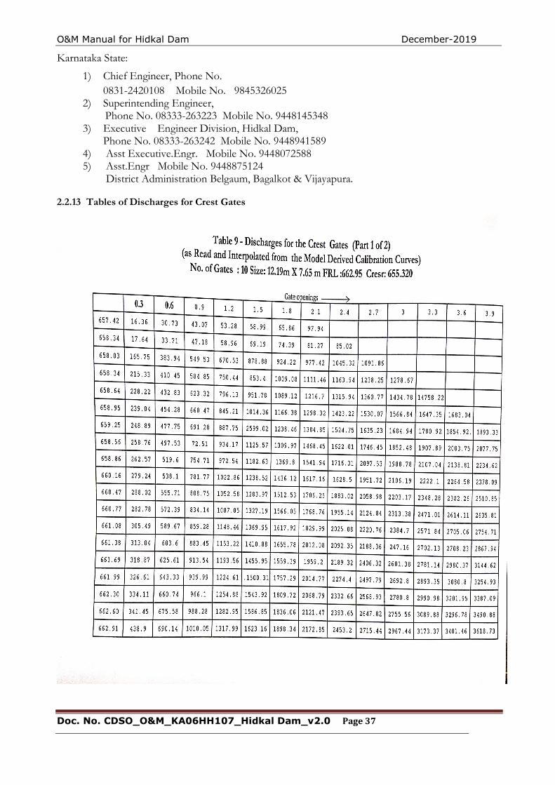
O&M Manual for Hidkal Dam December-2019
Doc. No. CDSO_O&M_KA06HH107_Hidkal Dam_v2.0 Page 37
Karnataka State:
1) Chief Engineer, Phone No. 0831-2420108 Mobile No. 9845326025
2) Superintending Engineer, Phone No. 08333-263223 Mobile No. 9448145348 3) Executive Engineer Division, Hidkal Dam, Phone No. 08333-263242 Mobile No. 9448941589 4) Asst Executive.Engr. Mobile No. 9448072588 5) Asst.Engr Mobile No. 9448875124
District Administration Belgaum, Bagalkot & Vijayapura.
2.2.13 Tables of Discharges for Crest Gates
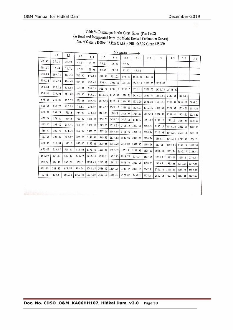
O&M Manual for Hidkal Dam December-2019
Doc. No. CDSO_O&M_KA06HH107_Hidkal Dam_v2.0 Page 38
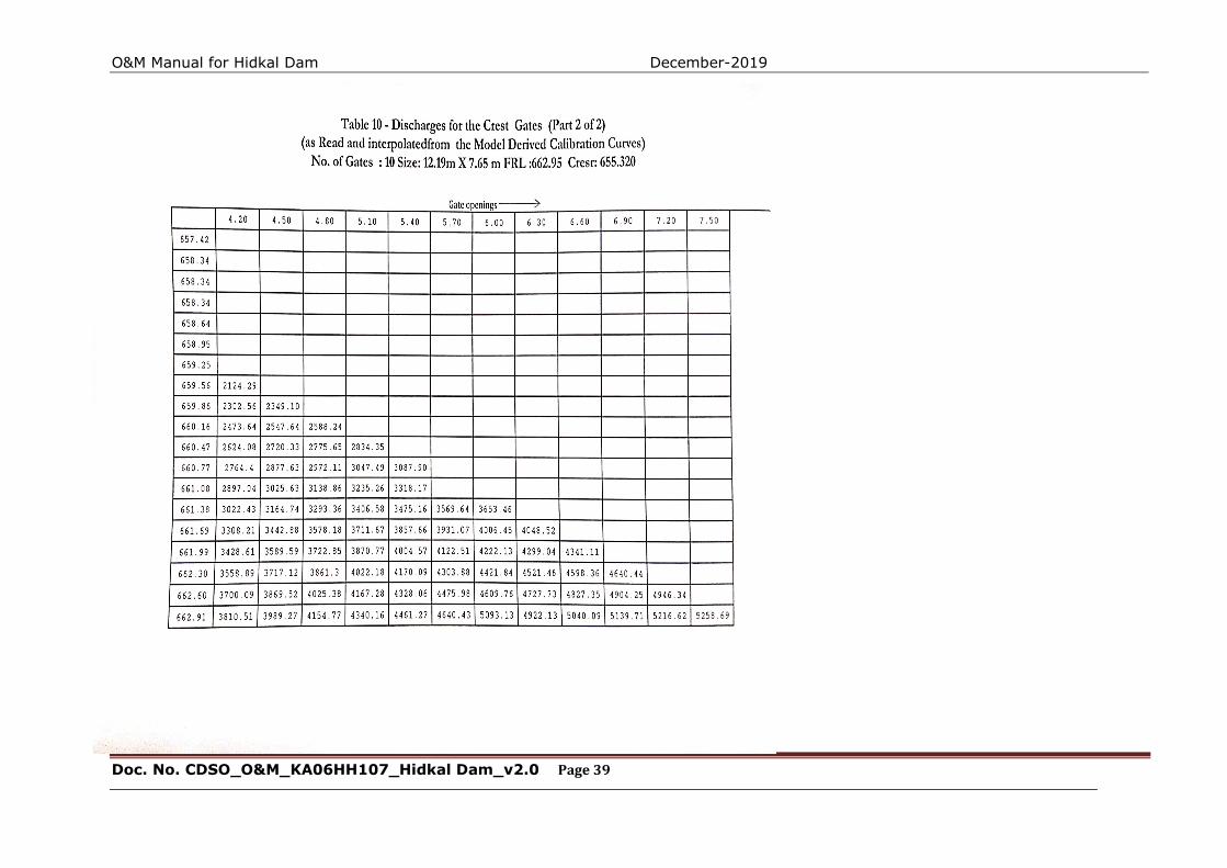
O&M Manual for Hidkal Dam December-2019
Doc. No. CDSO_O&M_KA06HH107_Hidkal Dam_v2.0 Page 39
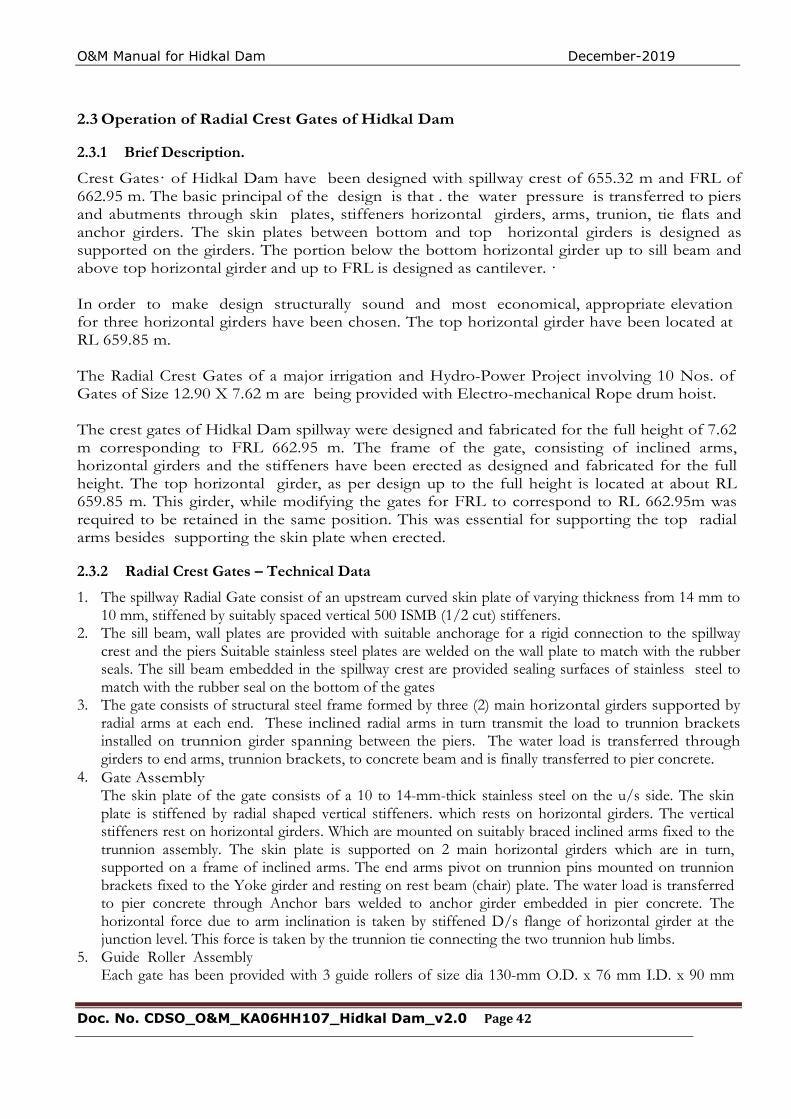
O&M Manual for Hidkal Dam December-2019
Doc. No. CDSO_O&M_KA06HH107_Hidkal Dam_v2.0 Page 42
2.3 Operation of Radial Crest Gates of Hidkal Dam
2.3.1 Brief Description.
Crest Gates· of Hidkal Dam have been designed with spillway crest of 655.32 m and FRL of 662.95 m. The basic principal of the design is that . the water pressure is transferred to piers and abutments through skin plates, stiffeners horizontal girders, arms, trunion, tie flats and anchor girders. The skin plates between bottom and top horizontal girders is designed as supported on the girders. The portion below the bottom horizontal girder up to sill beam and above top horizontal girder and up to FRL is designed as cantilever. · In order to make design structurally sound and most economical, appropriate elevation for three horizontal girders have been chosen. The top horizontal girder have been located at RL 659.85 m. The Radial Crest Gates of a major irrigation and Hydro-Power Project involving 10 Nos. of Gates of Size 12.90 X 7.62 m are being provided with Electro-mechanical Rope drum hoist. The crest gates of Hidkal Dam spillway were designed and fabricated for the full height of 7.62 m corresponding to FRL 662.95 m. The frame of the gate, consisting of inclined arms, horizontal girders and the stiffeners have been erected as designed and fabricated for the full height. The top horizontal girder, as per design up to the full height is located at about RL 659.85 m. This girder, while modifying the gates for FRL to correspond to RL 662.95m was required to be retained in the same position. This was essential for supporting the top radial arms besides supporting the skin plate when erected.
2.3.2 Radial Crest Gates – Technical Data
1. The spillway Radial Gate consist of an upstream curved skin plate of varying thickness from 14 mm to 10 mm, stiffened by suitably spaced vertical 500 ISMB (1/2 cut) stiffeners.
2. The sill beam, wall plates are provided with suitable anchorage for a rigid connection to the spillway crest and the piers Suitable stainless steel plates are welded on the wall plate to match with the rubber seals. The sill beam embedded in the spillway crest are provided sealing surfaces of stainless steel to match with the rubber seal on the bottom of the gates
3. The gate consists of structural steel frame formed by three (2) main horizontal girders supported by radial arms at each end. These inclined radial arms in turn transmit the load to trunnion brackets installed on trunnion girder spanning between the piers. The water load is transferred through girders to end arms, trunnion brackets, to concrete beam and is finally transferred to pier concrete.
4. Gate Assembly The skin plate of the gate consists of a 10 to 14-mm-thick stainless steel on the u/s side. The skin plate is stiffened by radial shaped vertical stiffeners. which rests on horizontal girders. The vertical stiffeners rest on horizontal girders. Which are mounted on suitably braced inclined arms fixed to the trunnion assembly. The skin plate is supported on 2 main horizontal girders which are in turn, supported on a frame of inclined arms. The end arms pivot on trunnion pins mounted on trunnion brackets fixed to the Yoke girder and resting on rest beam (chair) plate. The water load is transferred to pier concrete through Anchor bars welded to anchor girder embedded in pier concrete. The horizontal force due to arm inclination is taken by stiffened D/s flange of horizontal girder at the junction level. This force is taken by the trunnion tie connecting the two trunnion hub limbs.
5. Guide Roller Assembly Each gate has been provided with 3 guide rollers of size dia 130-mm O.D. x 76 mm I.D. x 90 mm
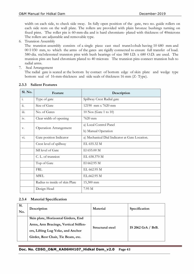
O&M Manual for Hidkal Dam December-2019
Doc. No. CDSO_O&M_KA06HH107_Hidkal Dam_v2.0 Page 43
width on each side, to check side sway. In fully open position of the gate, two no. guide rollers on each side rests on the wall plate. The rollers are provided with plain bronze bushings turning on fixed pins. The roller pin is 60-mm-dia and is hard chromium- plated with thickness of 40microns The rollers are adjustable and removable type.
6. Trunnion Assembly The trunnion assembly consists of a single piece cast steel trunn1o:hub having 10 680 mm and 00 I 030 mm, to which the arms of the gates are rigidly connected to ensure full transfer of load. 580-dia. sta1nlesssteel trunnion pins with bush bearings of size 580 I.D. x 680 O.D. are used. The trunnion pins are hard chromium plated to 40 microns The trunnion pins connect trunnion hub to radial arms.
7. Seal Arrangement The radial gate is seated at the bottom by contact of bottom edge of skin plate and wedge type bottom seal of 16-mm-thickness and side seals of thickness 16 mm (Z- Type).
2.3.3 Salient Features
Sl. No. Feature Description
i. Type of gate Spillway Crest Radial gate
ii. Size of Gate 12190 mm x 7620 mm
iii. No. of Gates 10 Nos (Gate 1 to 10)
iv. Clear width of opening 7620 mm
v. Operation Arrangement a) Local Control Panel
b) Manual Operation
vi. Gate position Indicator a) Mechanical Dial Indicator at Gate Location.
Crest level of spillway EL 655.32 M
Sill level of Gate El 655.00 M
C. L. of trunnion EL 658.370 M
Top of Gate El 662.95 M
FRL EL 662.95 M
MWL EL.662.95 M
Radius to inside of skin Plate 15,300 mm
Design Head 7.95 M
2.3.4 Material Specification
Sl.
No. Description Material Specification
Skin plate, Horizontal Girders, End
Arms, Arm Bracings, Vertical Stiffen-
ers, Lifting Lug Yoke, and Anchor
Girder, Rest Chair, Tie Beam, etc.
Structural steel IS 2062 GrA / BrB.
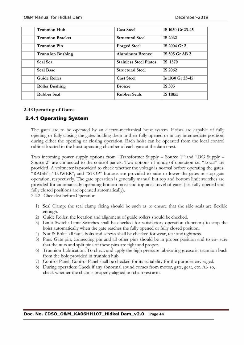
O&M Manual for Hidkal Dam December-2019
Doc. No. CDSO_O&M_KA06HH107_Hidkal Dam_v2.0 Page 44
Trunnion Hub Cast Steel IS 1030 Gr 23-45
Trunnion Bracket Structural Steel IS 2062
Trunnion Pin Forged Steel IS 2004 Gr 2
Trunn1on Bushing Aluminum Bronze IS 305 Gr AB 2
Seal Sea Stainless Steel Plates IS .1570
Seal Base Structural Steel IS 2062
Guide Roller Cast Steel Is 1030 Gr 23-45
Roller Bushing Bronze IS 305
Rubber Seal Rubber Seals IS 11855
2.4 Operating of Gates
2.4.1 Operating System The gates are to be operated by an electro-mechanical hoist system. Hoists are capable of fully opening or fully closing the gates holding them in their fully opened or in any intermediate position, during either the opening or closing operation. Each hoist can be operated from the local control cabinet located in the hoist operating chamber of each gate at the dam crest. Two incoming power supply options from “Transformer Supply – Source 1” and “DG Supply – Source 2” are connected to the control panels. Two options of mode of operation i.e. “Local” are provided. A voltmeter is provided to check whether the voltage is normal before operating the gates. “RAISE”, “LOWER”, and “STOP” buttons are provided to raise or lower the gates or stop gate operation, respectively. The gate operation is generally manual but top and bottom limit switches are provided for automatically operating bottom most and topmost travel of gates (i.e. fully opened and fully closed positions are operated automatically). 2.4.2 Checklist before Operation
1) Seal Clamp: the seal clamp fixing should be such as to ensure that the side seals are flexible enough.
2) Guide Roller: the location and alignment of guide rollers should be checked. 3) Limit Switch: Limit Switches shall be checked for satisfactory operation (function) to stop the
hoist automatically when the gate reaches the fully opened or fully closed position. 4) Nut & Bolts: all nuts, bolts and screws shall be checked for wear, tear and tightness. 5) Pins: Gate pin, connecting pin and all other pins should be in proper position and to en- sure
that the nuts and split pins of these pins are tight and proper. 6) Trunnion Lubrication: To check and apply the high pressure lubricating grease in trunnion bush
from the hole provided in trunnion hub. 7) Control Panel: Control Panel shall be checked for its suitability for the purpose envisaged. 8) During operation: Check if any abnormal sound comes from motor, gate, gear, etc. Al- so,
check whether the chain is properly aligned on chain rest arm.
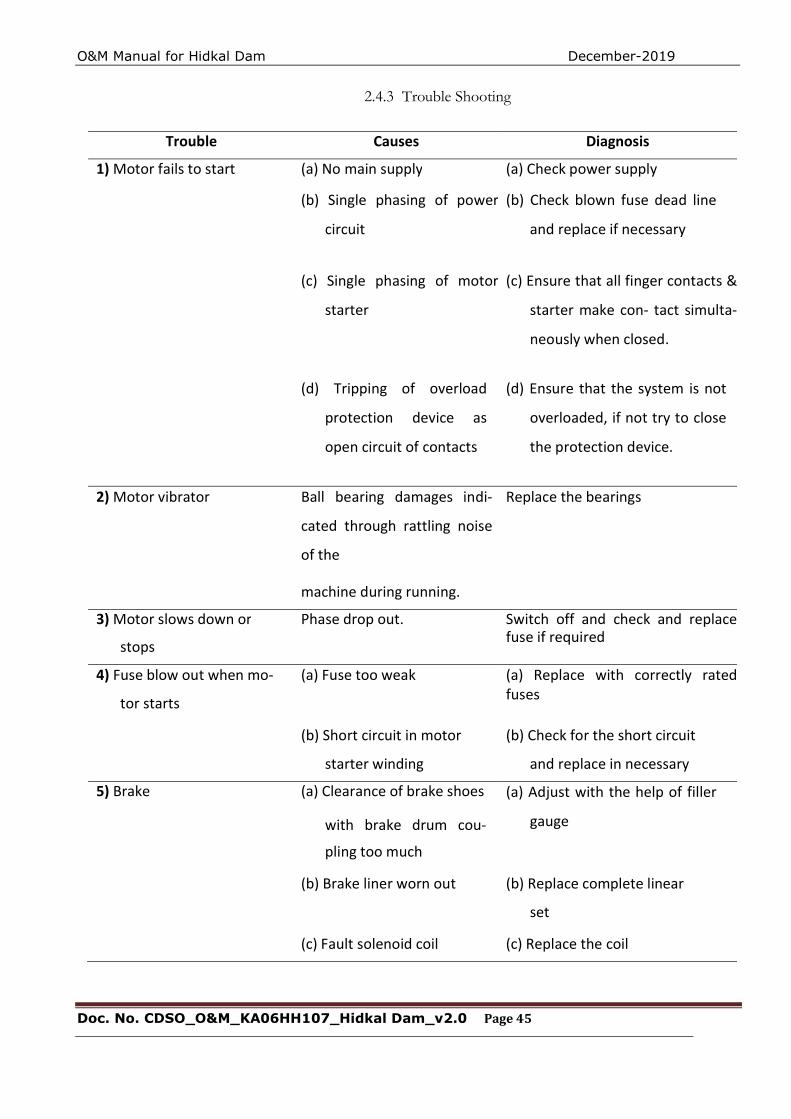
O&M Manual for Hidkal Dam December-2019
Doc. No. CDSO_O&M_KA06HH107_Hidkal Dam_v2.0 Page 45
2.4.3 Trouble Shooting
Trouble Causes Diagnosis
1) Motor fails to start (a) No main supply (a) Check power supply
(b) Single phasing of power
circuit
(b) Check blown fuse dead line
and replace if necessary
(c) Single phasing of motor
starter
(c) Ensure that all finger contacts &
starter make con- tact simulta-
neously when closed.
(d) Tripping of overload
protection device as
open circuit of contacts
(d) Ensure that the system is not
overloaded, if not try to close
the protection device.
2) Motor vibrator Ball bearing damages indi-
cated through rattling noise
of the
machine during running.
Replace the bearings
3) Motor slows down or
stops
Phase drop out. Switch off and check and replace fuse if required
4) Fuse blow out when mo-
tor starts
(a) Fuse too weak (a) Replace with correctly rated fuses
(b) Short circuit in motor
starter winding
(b) Check for the short circuit
and replace in necessary
5) Brake (a) Clearance of brake shoes
with brake drum cou-
pling too much
(a) Adjust with the help of filler
gauge
(b) Brake liner worn out (b) Replace complete linear
set
(c) Fault solenoid coil (c) Replace the coil
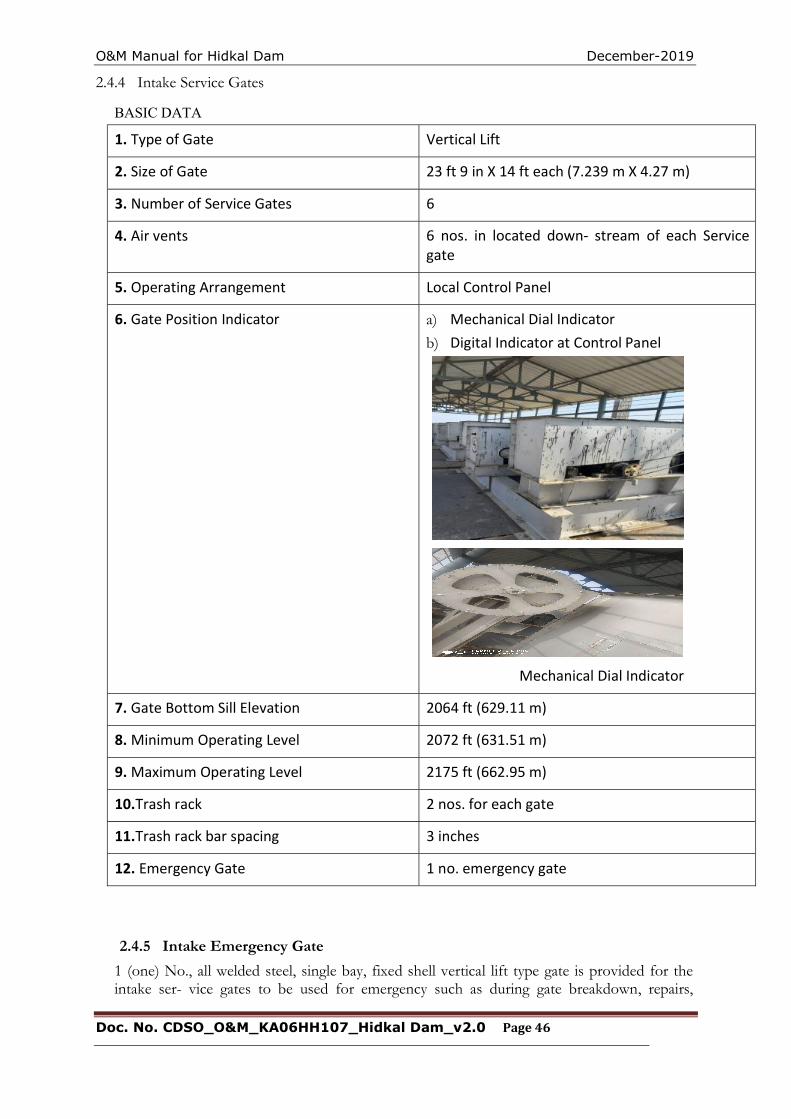
O&M Manual for Hidkal Dam December-2019
Doc. No. CDSO_O&M_KA06HH107_Hidkal Dam_v2.0 Page 46
2.4.4 Intake Service Gates
BASIC DATA
1. Type of Gate Vertical Lift
2. Size of Gate 23 ft 9 in X 14 ft each (7.239 m X 4.27 m)
3. Number of Service Gates 6
4. Air vents 6 nos. in located down- stream of each Service gate
5. Operating Arrangement Local Control Panel
6. Gate Position Indicator
a) Mechanical Dial Indicator b) Digital Indicator at Control Panel
Mechanical Dial Indicator
7. Gate Bottom Sill Elevation 2064 ft (629.11 m)
8. Minimum Operating Level 2072 ft (631.51 m)
9. Maximum Operating Level 2175 ft (662.95 m)
10.Trash rack 2 nos. for each gate
11.Trash rack bar spacing 3 inches
12. Emergency Gate 1 no. emergency gate
2.4.5 Intake Emergency Gate
1 (one) No., all welded steel, single bay, fixed shell vertical lift type gate is provided for the intake ser- vice gates to be used for emergency such as during gate breakdown, repairs,
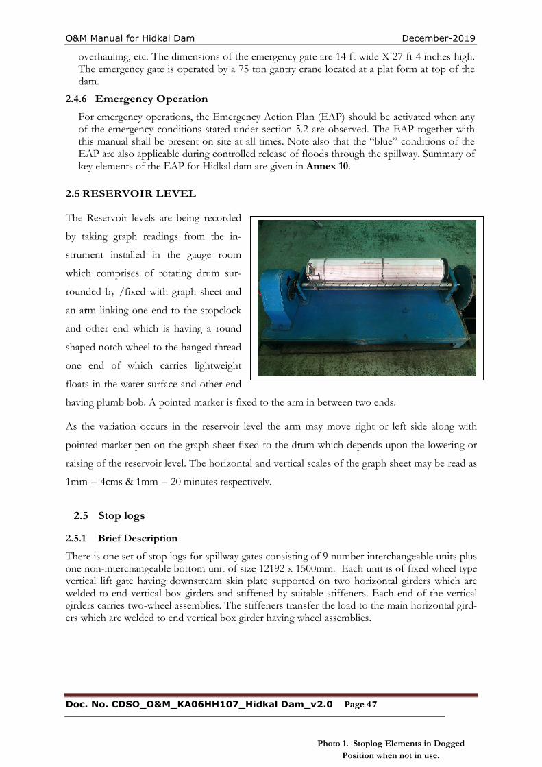
O&M Manual for Hidkal Dam December-2019
Doc. No. CDSO_O&M_KA06HH107_Hidkal Dam_v2.0 Page 47
Photo 1. Stoplog Elements in Dogged Position when not in use.
overhauling, etc. The dimensions of the emergency gate are 14 ft wide X 27 ft 4 inches high. The emergency gate is operated by a 75 ton gantry crane located at a plat form at top of the dam.
2.4.6 Emergency Operation
For emergency operations, the Emergency Action Plan (EAP) should be activated when any of the emergency conditions stated under section 5.2 are observed. The EAP together with this manual shall be present on site at all times. Note also that the “blue” conditions of the EAP are also applicable during controlled release of floods through the spillway. Summary of key elements of the EAP for Hidkal dam are given in Annex 10.
2.5 RESERVOIR LEVEL
The Reservoir levels are being recorded
by taking graph readings from the in-
strument installed in the gauge room
which comprises of rotating drum sur-
rounded by /fixed with graph sheet and
an arm linking one end to the stopclock
and other end which is having a round
shaped notch wheel to the hanged thread
one end of which carries lightweight
floats in the water surface and other end
having plumb bob. A pointed marker is fixed to the arm in between two ends.
As the variation occurs in the reservoir level the arm may move right or left side along with
pointed marker pen on the graph sheet fixed to the drum which depends upon the lowering or
raising of the reservoir level. The horizontal and vertical scales of the graph sheet may be read as
1mm = 4cms & 1mm = 20 minutes respectively.
2.5 Stop logs
2.5.1 Brief Description
There is one set of stop logs for spillway gates consisting of 9 number interchangeable units plus one non-interchangeable bottom unit of size 12192 x 1500mm. Each unit is of fixed wheel type vertical lift gate having downstream skin plate supported on two horizontal girders which are welded to end vertical box girders and stiffened by suitable stiffeners. Each end of the vertical girders carries two-wheel assemblies. The stiffeners transfer the load to the main horizontal gird-ers which are welded to end vertical box girder having wheel assemblies.
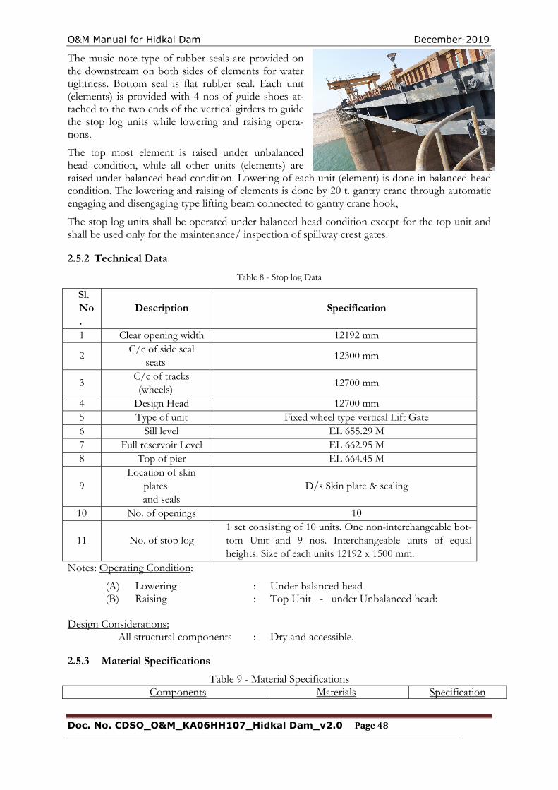
O&M Manual for Hidkal Dam December-2019
Doc. No. CDSO_O&M_KA06HH107_Hidkal Dam_v2.0 Page 48
The music note type of rubber seals are provided on the downstream on both sides of elements for water tightness. Bottom seal is flat rubber seal. Each unit (elements) is provided with 4 nos of guide shoes at-tached to the two ends of the vertical girders to guide the stop log units while lowering and raising opera-tions.
The top most element is raised under unbalanced head condition, while all other units (elements) are raised under balanced head condition. Lowering of each unit (element) is done in balanced head condition. The lowering and raising of elements is done by 20 t. gantry crane through automatic engaging and disengaging type lifting beam connected to gantry crane hook,
The stop log units shall be operated under balanced head condition except for the top unit and shall be used only for the maintenance/ inspection of spillway crest gates.
2.5.2 Technical Data
Table 8 - Stop log Data
Sl. No.
Description Specification
1 Clear opening width 12192 mm
2 C/c of side seal
seats 12300 mm
3 C/c of tracks (wheels)
12700 mm
4 Design Head 12700 mm 5 Type of unit Fixed wheel type vertical Lift Gate 6 Sill level EL 655.29 M 7 Full reservoir Level EL 662.95 M 8 Top of pier EL 664.45 M
9 Location of skin
plates and seals
D/s Skin plate & sealing
10 No. of openings 10
11 No. of stop log 1 set consisting of 10 units. One non-interchangeable bot-tom Unit and 9 nos. Interchangeable units of equal heights. Size of each units 12192 x 1500 mm.
Notes: Operating Condition:
(A) Lowering : Under balanced head (B) Raising : Top Unit - under Unbalanced head:
Design Considerations:
All structural components : Dry and accessible.
2.5.3 Material Specifications
Table 9 - Material Specifications Components Materials Specification
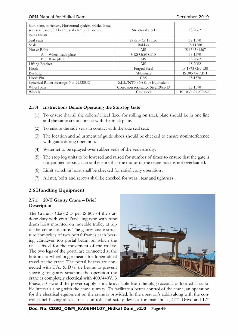
O&M Manual for Hidkal Dam December-2019
Doc. No. CDSO_O&M_KA06HH107_Hidkal Dam_v2.0 Page 49
Skin plate, stiffeners, Horizontal girders, tracks, Base, seal seat bases, Sill beam, seal clamp, Guide and guide shoes
Structural steel IS 2062
Seal seats SS Gr4 Cr 19 nilo IS 1570 Seals Rubber IS 11588 Nut & Bolts MS IS 1363/1367
A. Wheel track plate CRS Gr20 Cr13 IS 1570 B. Base plate MS IS 2062
Lifting Bracket MS IS 2062 Hook Forged Steel IS 1875 Grc-c30 Bushing Al-Bronze IS 305 Gr AB-1 Hook Pin CRS IS 1570 Spherical Roller Bearings No. 22328CC ZKL/NTN/NSK or Equivalent Wheel pins Corrosion resistance Steel 20cr-13 IS 1570 Wheels Cast steel IS 1030 Gr 270-520
2.5.4 Instructions Before Operating the Stop log Gate
(1) To ensure that all the rollers/wheel fixed for rolling on track plate should be in one line and the same are in contact with the track plate.
(2) To ensure the side seals in contact with the side seal seat.
(3) The location and adjustment of guide shoes should be checked to ensure noninterference with guide during operation.
(4) Water jet to be sprayed over rubber seals of the seals are dry.
(5) The stop log units to be lowered and raised for number of times to ensure that the gate is not jammed or stuck-up and ensure that the motor of the crane hoist is not overloaded.
(6) Limit switch in hoist shall be checked for satisfactory operation .
(7) All nut, bolts and screws shall be checked for wear , tear and tightness .
2.6 Handling Equipment
2.7.1 20-T Gantry Crane – Brief Description
The Crane is Class-2 as per IS 807 of the out-door duty with crab Travelling type with rope drum hoist mounted on movable trolley at top of the crane structure. The gantry crane struc-ture comprises of two portal frames each bear-ing cantilever top portal beam on which the rail is fixed for the movement of the trolley. The two legs of the portal are connected at the bottom to wheel bogie meant for longitudinal travel of the crane. The portal beams are con-nected with U/s. & D/s. tie beams to prevent skewing of gantry structure the operation the crane is completely electrical with 400/440V, 3 Phase, 50 Hz and the power supply is made available from the plug receptacles located at suita-ble intervals along with the crane runway. To facilitate a better control of the crane, an operation for the electrical equipment on the crane is provided. In the operator's cabin along with the con-trol panel having all electrical controls and safety devices for main hoist, C.T. Drive and L.T
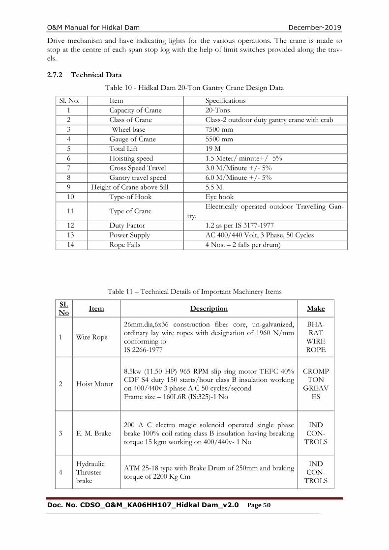
O&M Manual for Hidkal Dam December-2019
Doc. No. CDSO_O&M_KA06HH107_Hidkal Dam_v2.0 Page 50
Drive mechanism and have indicating lights for the various operations. The crane is made to stop at the centre of each span stop log with the help of limit switches provided along the trav-els.
2.7.2 Technical Data
Table 10 - Hidkal Dam 20-Ton Gantry Crane Design Data
Sl. No. Item Specifications 1 Capacity of Crane 20-Tons 2 Class of Crane Class-2 outdoor duty gantry crane with crab 3 Wheel base 7500 mm 4 Gauge of Crane 5500 mm 5 Total Lift 19 M 6 Hoisting speed 1.5 Meter/ minute+/- 5% 7 Cross Speed Travel 3.0 M/Minute +/- 5% 8 Gantry travel speed 6.0 M/Minute +/- 5% 9 Height of Crane above Sill 5.5 M 10 Type-of Hook Eye hook
11 Type of Crane Electrically operated outdoor Travelling Gan-
try. 12 Duty Factor 1.2 as per IS 3177-1977 13 Power Supply AC 400/440 Volt, 3 Phase, 50 Cycles 14 Rope Falls 4 Nos. – 2 falls per drum)
Table 11 – Technical Details of Important Machinery Items
SI. No
Item Description Make
1 Wire Rope
26mm.dia,6x36 construction fiber core, un-galvanized, ordinary lay wire ropes with designation of 1960 N/mm conforming to IS 2266-1977
BHA-RAT
WIRE ROPE
2 Hoist Motor
8.5kw (11.50 HP) 965 RPM slip ring motor TEFC 40% CDF S4 duty 150 starts/hour class B insulation working on 400/440v 3 phase A C 50 cycles/second Frame size – 160L6R (IS:325)-1 No
CROMPTON
GREAVES
3 E. M. Brake 200 A C electro magic solenoid operated single phase brake 100% coil rating class B insulation having breaking torque 15 kgm working on 400/440v- 1 No
IND CON-
TROLS
4 Hydraulic Thruster brake
ATM 25-18 type with Brake Drum of 250mm and braking torque of 2200 Kg Cm
IND CON-
TROLS

O&M Manual for Hidkal Dam December-2019
Doc. No. CDSO_O&M_KA06HH107_Hidkal Dam_v2.0 Page 51
5 Gear Box
Warm reducer Ratio 60:1 type “U” size 4” input H P 11.50 input speed 965 RPM output shaft with extension on either side having output torque 410kgm.
SHAN-THI
6
Plummer Block and bearing for 2nd Shaft
Plummer Block having SNA 522 with bearing No. 2222K adopter sleeve H-322, locating ring 2 FRR-13/200P STD
7
Plummer Block and bearing for 3rd Shaft
Plummer Block having SNA 516 with bearing No. 2216K, Sleeve H-318, locating ring 2 FRB-12.5/ 130P
STD
8 Motor for C.T Drive
2.1kw (2.85 HP) 880 RPM squirrel cage motor 40% CDF 150 starts per hour TEFC shaft extended on either sides working on 400/440v AC 3phase so cycles/sec confirm-ing to IS 325 frame size AMK112MG nos reqd : 2no
CROMPTON
GREAVES
9 E.M. Brake
for C.T. Driver
150 A C electro magtic solenoid operated single phase brake 100% coil rating class b insulation working on 400/440v A C 50 cycle/sec breaking torque capacity
4kgm -2 no s
IND CON-
TROLS
10
Plummer Block and bearing for
Pinion Shaft. for C.T. Drive
Plummer block SNA 513 Tc with bearing No. 1213K with locating ring 2FRB-14/120
STD
11 Bearing for Wheel shaft
SNA 516 - bearing 1216K adopter sleeve H316-2ring FRB 16/140P.
12 Wheel bear-ing for L. T.
drive
Spherical Roller Bearing No.73026CC/width-52mm ID/OD-130/200mm
NSK/NTN
13 Motor for L.
T. Drive
2 Nos. TCFC; Slipring Crane Duty Motor each having 4 KW @ 40% CDF, 890 RPM, working on 415/440V, 3
Phase, 50 Hz AC Electric supply, Motor frame size-130M (ILT 2133-6)
CROMPTON-
GREAVES
14 E. M. Brake for ASM-15 L.T. Drive
150mm dia brake drum (flexible coupling type) 70mm shoe width, single-phase, AC solenoid operated, spring set E.M Brake having breaking torque capacity of 850 KgCm
@ 100% coil rating
IND CON-TROL
15 Reduction Ratio for
L.T. Drive Two stage reduction box 300 HN
NU-TECK
16 Bearing for L.T. Gear
Wheel W 1
Spherical Roller 2 Nos. deed groove ball bearing No.6014, width 20mm ID/OD-70/110-mm.
NSK-NTN
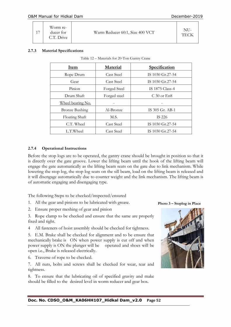
O&M Manual for Hidkal Dam December-2019
Doc. No. CDSO_O&M_KA06HH107_Hidkal Dam_v2.0 Page 52
Photo 3 – Stoplog in Place
17 Worm re-ducer for
C.T. Drive Warm Reducer 60:1, Size 400 VCT
NU-TECK
2.7.3 Material Specifications
Table 12 – Materials for 20-Ton Gantry Crane
Item Material Specification
Rope Drum Cast Steel IS 1030 Gr.27-54
Gear Cast Steel IS 1030 Gr.27-54
Pinion Forged Steel IS 1875 Class-4
Drum Shaft Forged steel C 30 or En8
Wheel bearing No. - -
Bronze Bushing Al-Bronze IS 305 Gr. AB-1
Floating Shaft M.S. IS 226
C.T. Wheel Cast Steel IS 1030 Gr.27-54
L.T.Wheel Cast Steel IS 1030 Gr.27-54
2.7.4 Operational Instructions
Before the stop logs are to be operated, the gantry crane should be brought in position so that it is directly over the gate groove. Lower the lifting beam until the hook of the lifting beam will engage the gate automatically as the lifting beam seats on the gate due to link mechanism. While lowering the stop log, the stop log seats on the sill beam, load on the lifting beam is released and it will disengage automatically due to counter weight and the link mechanism. The lifting beam is of automatic engaging and disengaging type.
The following Steps to be checked/inspected/ensured
1. All the gear and pinions to be lubricated with grease.
2. Ensure proper meshing of gear and pinion
3. Rope clamp to be checked and ensure that the same are properly fixed and tight.
4 All fasteners of hoist assembly should be checked for tightness.
5. E.M. Brake shall be checked for alignment and to be ensure that mechanically brake is ON when power supply is cut off and when power supply is ON the plunger will be operated and shoes will be open i.e., Brake is released electrically.
6. Traverse of rope to be checked.
7. All nuts, bolts and screws shall be checked for wear, tear and tightness.
8. To ensure that the lubricating oil of specified gravity and make should be filled to the desired level in worm reducer and gear box.
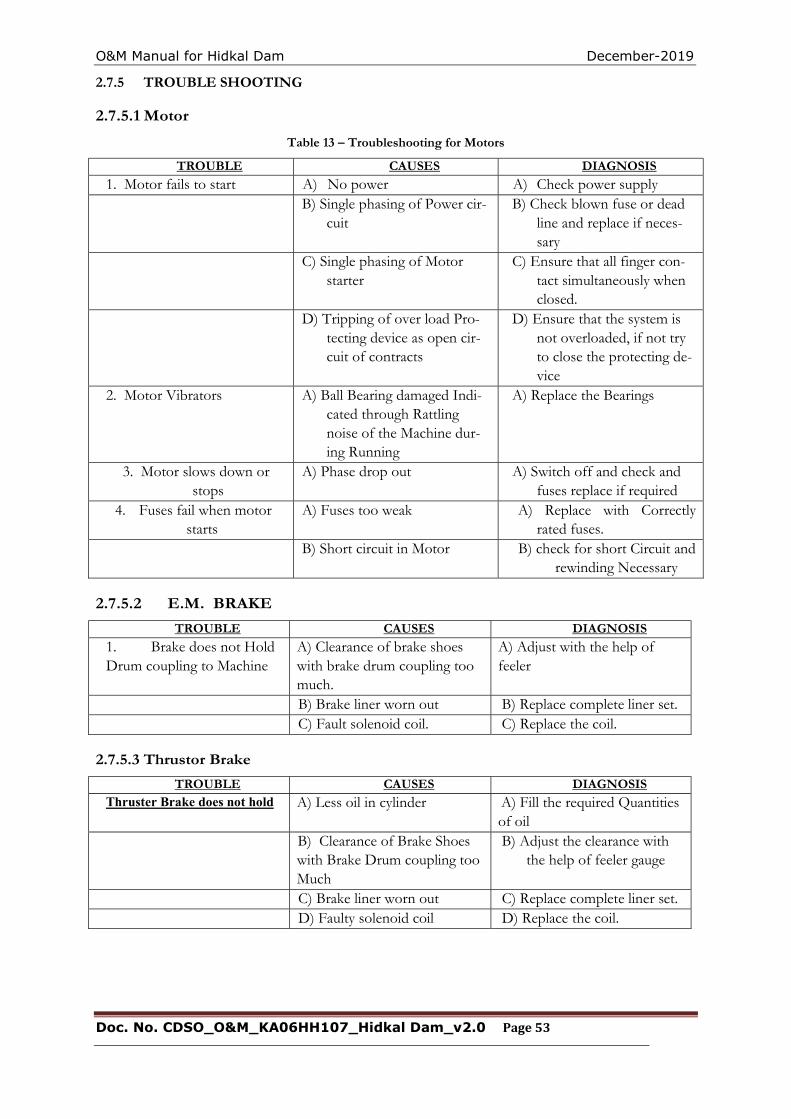
O&M Manual for Hidkal Dam December-2019
Doc. No. CDSO_O&M_KA06HH107_Hidkal Dam_v2.0 Page 53
2.7.5 TROUBLE SHOOTING
2.7.5.1 Motor
Table 13 – Troubleshooting for Motors
TROUBLE CAUSES DIAGNOSIS
1. Motor fails to start A) No power A) Check power supply B) Single phasing of Power cir-
cuit B) Check blown fuse or dead
line and replace if neces-sary
C) Single phasing of Motor starter
C) Ensure that all finger con-tact simultaneously when closed.
D) Tripping of over load Pro-tecting device as open cir-cuit of contracts
D) Ensure that the system is not overloaded, if not try to close the protecting de-vice
2. Motor Vibrators A) Ball Bearing damaged Indi-cated through Rattling noise of the Machine dur-ing Running
A) Replace the Bearings
3. Motor slows down or stops
A) Phase drop out A) Switch off and check and fuses replace if required
4. Fuses fail when motor starts
A) Fuses too weak A) Replace with Correctly rated fuses.
B) Short circuit in Motor B) check for short Circuit and rewinding Necessary
2.7.5.2 E.M. BRAKE
TROUBLE CAUSES DIAGNOSIS
1. Brake does not Hold Drum coupling to Machine
A) Clearance of brake shoes with brake drum coupling too much.
A) Adjust with the help of feeler
B) Brake liner worn out B) Replace complete liner set. C) Fault solenoid coil. C) Replace the coil.
2.7.5.3 Thrustor Brake
TROUBLE CAUSES DIAGNOSIS Thruster Brake does not hold A) Less oil in cylinder A) Fill the required Quantities
of oil B) Clearance of Brake Shoes
with Brake Drum coupling too Much
B) Adjust the clearance with the help of feeler gauge
C) Brake liner worn out C) Replace complete liner set. D) Faulty solenoid coil D) Replace the coil.
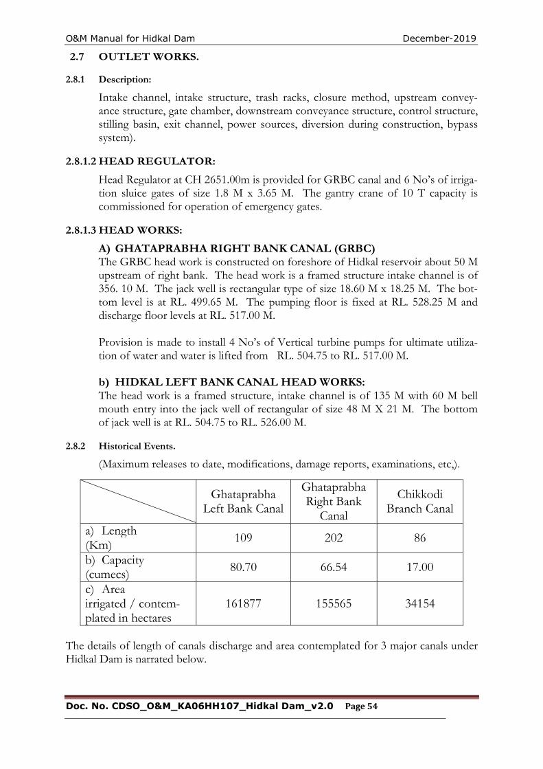
O&M Manual for Hidkal Dam December-2019
Doc. No. CDSO_O&M_KA06HH107_Hidkal Dam_v2.0 Page 54
2.7 OUTLET WORKS.
2.8.1 Description:
Intake channel, intake structure, trash racks, closure method, upstream convey-ance structure, gate chamber, downstream conveyance structure, control structure, stilling basin, exit channel, power sources, diversion during construction, bypass system).
2.8.1.2 HEAD REGULATOR:
Head Regulator at CH 2651.00m is provided for GRBC canal and 6 No’s of irriga-tion sluice gates of size 1.8 M x 3.65 M. The gantry crane of 10 T capacity is commissioned for operation of emergency gates.
2.8.1.3 HEAD WORKS:
A) GHATAPRABHA RIGHT BANK CANAL (GRBC) The GRBC head work is constructed on foreshore of Hidkal reservoir about 50 M upstream of right bank. The head work is a framed structure intake channel is of 356. 10 M. The jack well is rectangular type of size 18.60 M x 18.25 M. The bot-tom level is at RL. 499.65 M. The pumping floor is fixed at RL. 528.25 M and discharge floor levels at RL. 517.00 M.
Provision is made to install 4 No’s of Vertical turbine pumps for ultimate utiliza-tion of water and water is lifted from RL. 504.75 to RL. 517.00 M.
b) HIDKAL LEFT BANK CANAL HEAD WORKS: The head work is a framed structure, intake channel is of 135 M with 60 M bell mouth entry into the jack well of rectangular of size 48 M X 21 M. The bottom of jack well is at RL. 504.75 to RL. 526.00 M.
2.8.2 Historical Events.
(Maximum releases to date, modifications, damage reports, examinations, etc,).
The details of length of canals discharge and area contemplated for 3 major canals under Hidkal Dam is narrated below.
Ghataprabha
Left Bank Canal
Ghataprabha Right Bank
Canal
Chikkodi Branch Canal
a) Length (Km)
109 202 86
b) Capacity (cumecs) 80.70 66.54 17.00
c) Area irrigated / contem-plated in hectares
161877 155565 34154
O&M Manual for Hidkal Dam December-2019
Doc. No. CDSO_O&M_KA06HH107_Hidkal Dam_v2.0 Page 55
2.8.3 Operation:
2.8.3.1 General
Water is released when the water level depletes below crest level of 629.10 M through river sluices safely as per the requirements for irrigation purpose. The water is being let out through the irrigation sluice gates for GRBC canal for irriga-tion purpose.
2.8.3.2 Restrictions:
There are no restrictions for operation of irrigation sluice gates as per water re-quirements and discharge in GRBC,and CBC canal.and there are no restrictions for operation of penstock for GLBC canal.
2.8.3.3 Mechanical:
Irrigation Sluice Gates are operated by electrical power and incase of power fail-ure, these gates can be operated through generator.
2. 8. 4 References:
2.8.4.1 Reports and Data.
1) Ghataprabha Project Report 1986 2) Stage – II 2000
2.8.4.2 Drawings:
1) General Layout plan showing locations of Left & Right Head Works 2) Drawing of River Sluice is enclosed vide ANNEXURE -II.
2.9 POWER OUTLETS
2.9.1 Description
(Intake structures, trash racks, closure method, penstocks, turbines, tailrace, exit channel, etc.) Hidkal Dam Power House is situated at the foot of Hidkal Dam on the left bank of the river Ghataprabha. The power house has consists of a total of two generating units, each 16 MW ( total 32 MW Capacity) Following are the Power outlets details. Intake structure:
Mainly penstock gate operation (arrangements for entry of water into penstock gates) Trash racks:
I. Two (2) Nos. of trash rack vents for unit-1 and 2 clear size = 3.353 X 5.791 m.
Closure method: Automatic / Manually operated hydraulic penstock gates. Penstocks:
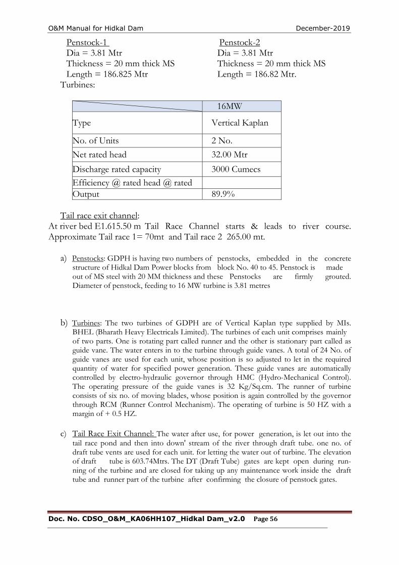
O&M Manual for Hidkal Dam December-2019
Doc. No. CDSO_O&M_KA06HH107_Hidkal Dam_v2.0 Page 56
Penstock-1 Penstock-2 Dia = 3.81 Mtr Dia = 3.81 Mtr Thickness = 20 mm thick MS Thickness = 20 mm thick MS Length = 186.825 Mtr Length = 186.82 Mtr. Turbines:
16MW
Type Vertical Kaplan
No. of Units 2 No.
Net rated head 32.00 Mtr
Discharge rated capacity 3000 Cumecs
Efficiency @ rated head @ rated Output 89.9%
Tail race exit channel: At river bed E1.615.50 m Tail Race Channel starts & leads to river course. Approximate Tail race 1= 70mt and Tail race 2 265.00 mt.
a) Penstocks: GDPH is having two numbers of penstocks, embedded in the concrete structure of Hidkal Dam Power blocks from block No. 40 to 45. Penstock is made out of MS steel with 20 MM thickness and these Penstocks are firmly grouted. Diameter of penstock, feeding to 16 MW turbine is 3.81 metres
b) Turbines: The two turbines of GDPH are of Vertical Kaplan type supplied by MIs. BHEL (Bharath Heavy Electricals Limited). The turbines of each unit comprises mainly of two parts. One is rotating part called runner and the other is stationary part called as guide vane. The water enters in to the turbine through guide vanes. A total of 24 No. of guide vanes are used for each unit, whose position is so adjusted to let in the required quantity of water for specified power generation. These guide vanes are automatically controlled by electro-hydraulic governor through HMC (Hydro-Mechanical Control). The operating pressure of the guide vanes is 32 Kg/Sq.cm. The runner of turbine consists of six no. of moving blades, whose position is again controlled by the governor through RCM (Runner Control Mechanism). The operating of turbine is 50 HZ with a margin of + 0.5 HZ.
c) Tail Race Exit Channel: The water after use, for power generation, is let out into the tail race pond and then into down' stream of the river through draft tube. one no. of draft tube vents are used for each unit. for letting the water out of turbine. The elevation of draft tube is 603.74Mtrs. The DT (Draft Tube) gates are kept open during run-ning of the turbine and are closed for taking up any maintenance work inside the draft tube and runner part of the turbine after confirming the closure of penstock gates.
O&M Manual for Hidkal Dam December-2019
Doc. No. CDSO_O&M_KA06HH107_Hidkal Dam_v2.0 Page 57
2.9.2General
Good condition. The Penstock, Turbines and Tail race exit channels are all in good con-dition.
2.9.3 Deficiencies and Problems
No deficiencies or problems have been observed, in above said components of the pow-er house, since its inception. Historical Events.
(Damage reports major malfunctions, examinations, etc.) Damage reports : None Major malfunctions : No malfunctions
Examination : Satisfactory results on examinations. No damages or malfunctions have happened so far in power outlets of Hidkal dam.
2.9.4 Hydraulic Design.
Penstock gates are hydraulically operated, normally operated from the Control room of Power House.
2.9.5 Normal Operation (discharge)
The turbines of Both Unit are designed for a discharge of 2504.88 Cusecs of water at its rated capacity. However, a maximum of 2828.0448 Cusecs of water can be discharged through it.
2.9.6 Use with Evacuation of Reservoir.
During post monsoon season, the water from Hidkal Dam is evacuated through the generating units of PH for meeting the irrigation requirement on downstream of Dam.
2.10 Operation
2.10.1 General: Generally the PH units are run at their rated capacity provided sufficient water head is available. All the units are operated and controlled from a single control room, using SCADA (Supervisory control and data acquisition) software technology, and monitored round the clock. However PH units are bound to discharge only the required amount of water from Hidkal dam for meeting the irrigation demand from downstream of dam. Minimum draw down level of first unit is 631.55 Mtr. Efficiency of turbine at rated capacity is 89.90%. 2.10.2 Restrictions: Main restriction for the operation of PH Turbine units is the water limitation from KNNL, which in turn depends upon the irrigation demand from irrigation canals. During monsoon floods, due to huge amount of water discharge from Hidkal Dam raises the level of Tail race of the power house very high. This reduces the net head drastically so low as up to 23 Mtr, which restricts the power generation. Usually our generation during this period will be around 90% of rated capacity. However, more than 100% power generation at PH can be achieved during
O&M Manual for Hidkal Dam December-2019
Doc. No. CDSO_O&M_KA06HH107_Hidkal Dam_v2.0 Page 58
rainy/flood season, if water level at dam is maintained at MDDL. 2.10.3 Mechanical The penstock pipes provided with a butterfly valve of 400mm dia which is opened using oil pressure of 30kg while generation/running of the unit.
2.10.4 Flood and Emergency Conditions During monsoon season the mighty river Ghataprabha at Hidkal receives huge amount of water as flood usually about for thousands of cusecs for months to-gether. Maximum permissible water is let out through PH generating units during this period. About 2504.88 cusecs @ head 662.94 of excess flood water is released through PH generating units.
2.11 ACCESS ROADS
2.11.1 Description
(Type of road, length, bridges, maintaining agency, etc.) Type of road: Asphalt road. Length: 1.60 km Bridges: 01 Maintaining agency: Maintaining departmentally.
2.11.2 Condition: 2.11.3 General: Road is in good condition
2.12 Record Keeping
Operating a dam includes keeping accurate records of items pertaining to project opera-tion. These include but not limited to the following: -
1. Rainfall and Reservoir Levels – On daily basis during non-monsoon and on hourly basis during monsoon. (see Chapters 2, 3 and 4 for detailed instructions and proce-dures)
2. Release through outlet/sluices on daily basis for irrigation, water supply, hydropower etc.
3. Outflows through spillway during monsoon on hourly basis. 4. Records of drawdown with reservoir levels, quantity of water released, drawdown
rates, reason for drawdown. 5. Other Procedures – Maintain a complete record of all operating procedures for gates,
sluices and remote-control operating system.
O&M Manual for Hidkal Dam December-2019
Doc. No. CDSO_O&M_KA06HH107_Hidkal Dam_v2.0 Page 59
CHAPTER 3 - PROJECT INSPECTIONS
The current practice of Inspection at Hidkal dam envisages the Sub division Officers to carryout pre-monsoon and post-monsoon inspections. The checklist Performa included in this chapter is currently in use at Hidkal dam.
Detailed description on project inspections is available in the Guideline for Safety Inspection of dams (Doc No. CDSO_GUD_DS_07_ v1.0), CWC 2018 (https://damsafety.in/ecm-includes/PDFs/Guidelines_for_Safety_Inspection_of_Dams. pdf). However an overview of the various types of inspections to be carried out at Hidkal dam is given below. Note that for uploading Inspection Data into DHARMA, the Inspection Instructions & Forms given in the aforementioned Guideline for Safety Inspection of Dams must be used (see Appendix 4). An effective inspection program is essential to identify problems and to keep Hidkal Dam in a good and healthy condition. This Chapter provides guidance on carrying out these inspections.
3.1 Types of Inspections
Four different types of dam safety inspections are available for being carried out at Hidkal Dam. These include, but not limited, to the following:
1. Comprehensive evaluation inspections
2. Scheduled inspections (Pre & Post monsoon inspections & other scheduled inspections)
3. Special (unscheduled) inspections
4. Informal inspections
The frequency of each type of inspection depends on the condition of the dam and State DSO regulations, etc.
Typical inspection elements and the detail of the safety inspections are provided below. More detailed descriptions are given in the ‘Guideline for Safety Inspection of Dams’ (CWC 2018). A checklist has been modified from the guideline to fit Hidkal requirements and is found in Appendix 5. This comphrehensive checklist allows for recording the status of each item being inspected and the overall condition of the equipment along with any consequential risks the condition may have on the health of the dam.
3.1.1 Comprehensive Evaluation Inspections
For comprehensive dam safety evaluation, an independent panel of experts known as Dam Safety Review Panel (DSRP) needs to be constituted for determining the condition of the dam and ap-purtenant works. The panel will undertake evaluation of the dam once in 10 years or on occur-rence of any extreme hydrological or seismic event or any unusual condition of the dam or in the reservoir rim. The terms of reference of the comprehensive dam safety evaluation shall include but not be limited to;
1. General assessment of hydrologic and hydraulic conditions, review of design flood, flood rout-ing for revised design flood and mitigation measures.
Review and analysis of available data of dam design including seismic safety, construc-tion, operation maintenance and performance of dam structure and appurtenant works.
O&M Manual for Hidkal Dam December-2019
Doc. No. CDSO_O&M_KA06HH107_Hidkal Dam_v2.0 Page 60
Evaluation of procedures for operation, maintenance and inspection of dam and to suggest improvements / modifications.
Evaluation of any possible hazardous threat to the dam structure such as dam abut-ment slope stability failure or slope failures along the reservoir periphery.
A comprehensive evaluation inspection of Hidkal consists of five major parts:
1. Review of project records (i.e. study of all design / construction records/drawings, history of the dam’s performance, past inspection notes/reports, notes on distress observed/ any rehabilitation measures undertaken earlier, instrumentation data and its interpretation.
2. Inspection of the dam and its appurtenant works.
3. To review the results and reports of additional field investigations & laboratory testing as required.
4. Review of design studies e.g. review of design flood, checking of the adequacy of spillway capacity, freeboard requirements, dam stability, any special study as required.
5. Preparation of a detailed report of the inspection.
3.1.2 Scheduled Inspections
Scheduled inspections shall consist of Pre-monsoon & Post-monsoon inspection and any other inspections carried out by the State Dam Safety Organisation / any Expert panels constituted by the dam owner.
These inspections are performed to gather information on the current condition of the dam and its appurtenant works. This information is then used to establish needed repairs and repair schedules, and to assess the safety and operational adequacy of the dam. Scheduled inspections are also performed to evaluate previous repairs.
The purpose of scheduled inspections is to keep the dam and its appurtenant structures in good operating condition and to maintain a safe structure. As such, these inspections and timely maintenance will minimize long-term costs and will extend the life of the dam. Scheduled inspections are performed more frequently than comprehensive evaluation inspections to detect at an early stage any developments that may be detrimental to the dam. These inspections involve assessing operational capability as well as structural stability and detection of any problems and to correct them before the conditions worsen. The field examinations should be made by the personnel assigned responsibility for monitoring the safety of the dam. If the dam or appurtenant works have instrumentation, the individual responsible for monitoring should analyze measurements as they are received and include an evaluation of that data. Dam Inspection Report or an inspection brief should be prepared following the field visit (Dam Inspection Report is recommended).
Scheduled inspections include the following four components as a minimum:
File review of past inspection reports, monitoring data, photographs, maintenance records, or other pertinent data as may be required;
Visual inspection of the dam and its appurtenant works;
O&M Manual for Hidkal Dam December-2019
Doc. No. CDSO_O&M_KA06HH107_Hidkal Dam_v2.0 Page 61
Preparation of a report or inspection brief, with relevant documentation and photographs. The report should be filed in the dam owner’s project files.
3.1.3 Special (Unscheduled) Inspections
Special inspections may need to be performed to resolve specific concerns or conditions at the site on an unscheduled basis. Special inspections are not regularly scheduled activities, but are usually made before or immediately after the dam or appurtenant works have been subjected to unusual events or conditions, such as an unusually high flood or a significant earthquake. These inspections are to be carried out after an initial assessment based on informal inspection carried out by project personnel reveal dam safety related concerns like cracking in the dam, damages, erosion/ scour, undermining/ piping/ sink holes/ liquefaction or any such undesirable feature. A special inspection may also be performed during an emergency, such as an impending dam breach, to evaluate specific areas or concerns. They are also made when the ongoing surveillance program identifies a condition or a trend that appears to warrant a special evaluation. Special inspections should focus on those dam components that are affected by the unusual event and should include at least three elements: 1) review of relevant files or data, 2) visual inspection, and 3) report preparation.
More detailed site investigations / studies may be required (such as drilling, surveys, or seepage flow estimates) if the special inspection reveals the need for the same. Photographic documentation is to be included as part of the inspection.
Japan Water Agency (JWA) has developed a system of carrying out inspections after an earthquake event for Ichari Dam, Uttarakhand. For details refer “Inspection Manual for Dam Field Engineers after Seismic Events, Ichari Dam, Uttarakhand (CDSO_GUD_DS_0_v1.0, September 2017). The manual is available at the following link: https://damsafety.in/ecm-includes/PDFs/Inspection_Manual_for_Dam_Field_Engineers_After_Seismic_Events.pdf
3.1.4 Informal Inspections
The last type of inspection, an informal inspection, is a continuing effort by on-site personnel (dam owners/operators and maintenance personnel) performed during their routine duties. Informal inspections are critical to the proper operation and maintenance of the dam. They consist of frequent observations of the general appearance and functioning of the dam and appurtenant structures.
Operators, maintenance crews, or other staff who are posted at Hidkal dam site conduct informal inspections. These people are the “first-line of defense” in assuring safe dam conditions, and it is their responsibility to be familiar with all aspects of the dam. Their vigilance in walking the dam, checking the operating equipment, and noting changes in conditions may prevent serious mishaps or even dam failures.
Informal inspections are important and are performed at every available opportunity. These inspections may only cover one or two dam components as the occasion presents itself, or they may cover the entire dam and its appurtenant structures. The informal inspections are not as detailed as comprehensive evaluation, scheduled, and special inspections and will only require that a formal report is submitted to the dam owner’s project files if a condition is detected that might endanger the dam. Report is to be
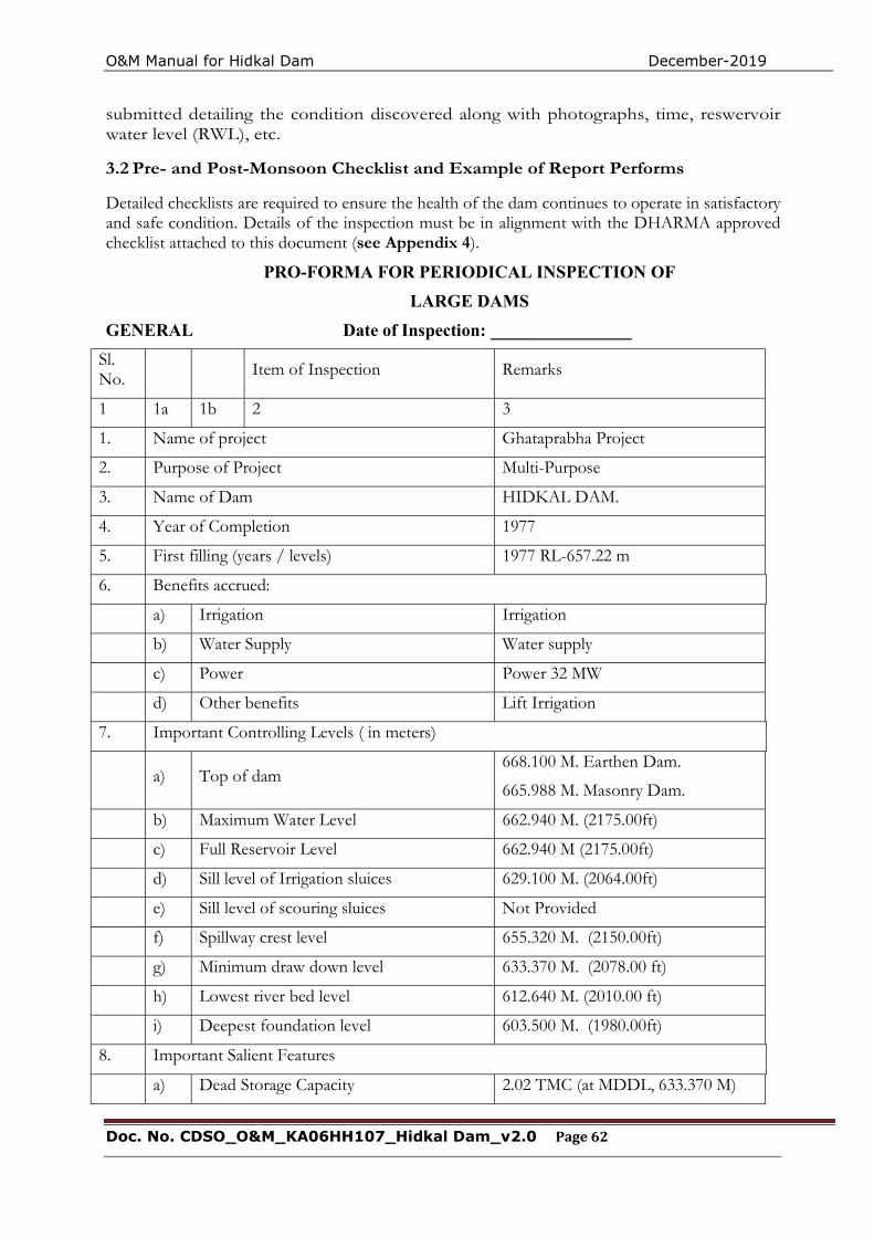
O&M Manual for Hidkal Dam December-2019
Doc. No. CDSO_O&M_KA06HH107_Hidkal Dam_v2.0 Page 62
submitted detailing the condition discovered along with photographs, time, reswervoir water level (RWL), etc.
3.2 Pre- and Post-Monsoon Checklist and Example of Report Performs
Detailed checklists are required to ensure the health of the dam continues to operate in satisfactory and safe condition. Details of the inspection must be in alignment with the DHARMA approved checklist attached to this document (see Appendix 4).
PRO-FORMA FOR PERIODICAL INSPECTION OF
LARGE DAMS
GENERAL Date of Inspection: ________________
Sl. No. Item of Inspection Remarks
1 1a 1b 2 3
1. Name of project Ghataprabha Project
2. Purpose of Project Multi-Purpose
3. Name of Dam HIDKAL DAM.
4. Year of Completion 1977
5. First filling (years / levels) 1977 RL-657.22 m
6. Benefits accrued:
a) Irrigation Irrigation
b) Water Supply Water supply
c) Power Power 32 MW
d) Other benefits Lift Irrigation
7. Important Controlling Levels ( in meters)
a) Top of dam 668.100 M. Earthen Dam.
665.988 M. Masonry Dam.
b) Maximum Water Level 662.940 M. (2175.00ft)
c) Full Reservoir Level 662.940 M (2175.00ft)
d) Sill level of Irrigation sluices 629.100 M. (2064.00ft)
e) Sill level of scouring sluices Not Provided
f) Spillway crest level 655.320 M. (2150.00ft)
g) Minimum draw down level 633.370 M. (2078.00 ft)
h) Lowest river bed level 612.640 M. (2010.00 ft)
i) Deepest foundation level 603.500 M. (1980.00ft)
8. Important Salient Features
a) Dead Storage Capacity 2.02 TMC (at MDDL, 633.370 M)
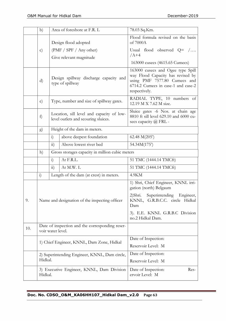
O&M Manual for Hidkal Dam December-2019
Doc. No. CDSO_O&M_KA06HH107_Hidkal Dam_v2.0 Page 63
b) Area of foreshore at F.R. L 78.03 Sq.Km.
c)
Design flood adopted
(PMF / SPF / Any other)
Give relevant magnitude
Flood formula revised on the basis of 7000A
Usual flood observed Q= /…. /A+4
163000 cusecs (4615.65 Cumecs)
d) Design spillway discharge capacity and type of spillway
163000 cusecs and Ogee type Spill way Flood Capacity has revised by using PMF 7577.80 Cumecs and 6714.2 Cumecs in case-1 and case-2 respectively.
e) Type, number and size of spillway gates. RADIAL TYPE, 10 numbers of 12.19 M X 7.62 M size.
f) Location, sill level and capacity of low-level outlets and scouring sluices.
Sluice gates -6 Nos. at chain age 8810 ft sill level 629.10 and 6000 cu-secs capacity @ FRL -
g) Height of the dam in meters.
i) above deepest foundation 62.48 M(205’)
ii) Above lowest river bed 54.34M(175’)
h) Gross storages capacity in million cubic meters
i) At F.R.L. 51 TMC (1444.14 TMCft)
ii) At M.W. L 51 TMC (1444.14 TMCft)
i) Length of the dam (at crest) in meters. 4.9KM
9. Name and designation of the inspecting officer
1) Shri, Chief Engineer, KNNL irri-gation (north) Belgaum
2)Shri. Superintending Engineer, KNNL, G.R.B.C.C. circle Hidkal Dam
3). E.E. KNNL G.R.B.C Division no.2 Hidkal Dam.
10. Date of inspection and the corresponding reser-voir water level.
1) Chief Engineer, KNNL, Dam Zone, Hidkal Date of Inspection:
Reservoir Level: M
2) Superintending Engineer, KNNL, Dam circle, Hidkal.
Date of Inspection:
Reservoir Level: M
3) Executive Engineer, KNNL, Dam Division Hidkal.
Date of Inspection: Res-ervoir Level: M
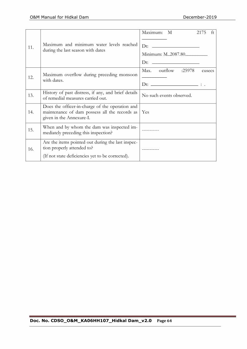
O&M Manual for Hidkal Dam December-2019
Doc. No. CDSO_O&M_KA06HH107_Hidkal Dam_v2.0 Page 64
11. Maximum and minimum water levels reached during the last season with dates
Maximum: M 2175 ft __________
Dt: ___________________
Minimum: M_2087.80_________
Dt: ___________________
12. Maximum overflow during preceding monsoon with dates.
Max. outflow :25978 cusecs __________
Dt: ___________________ : .
13. History of past distress, if any, and brief details of remedial measures carried out. No such events observed.
14. Does the officer-in-charge of the operation and maintenance of dam possess all the records as given in the Annexure-I.
Yes
15. When and by whom the dam was inspected im-mediately preceding this inspection? -----------
16. Are the items pointed out during the last inspec-tion properly attended to?
(If not state deficiencies yet to be corrected). -----------
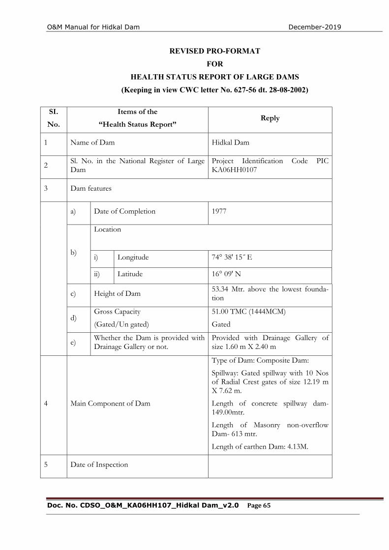
O&M Manual for Hidkal Dam December-2019
Doc. No. CDSO_O&M_KA06HH107_Hidkal Dam_v2.0 Page 65
REVISED PRO-FORMAT
FOR
HEALTH STATUS REPORT OF LARGE DAMS
(Keeping in view CWC letter No. 627-56 dt. 28-08-2002)
SI.
No.
Items of the
“Health Status Report” Reply
1 Name of Dam Hidkal Dam
2 Sl. No. in the National Register of Large Dam
Project Identification Code PIC KA06HH0107
3 Dam features
a) Date of Completion 1977
b)
Location
i) Longitude 74° 38' 15˝ E
ii) Latitude 16° 09' N
c) Height of Dam 53.34 Mtr. above the lowest founda-tion
d) Gross Capacity
(Gated/Un gated)
51.00 TMC (1444MCM)
Gated
e) Whether the Dam is provided with Drainage Gallery or not.
Provided with Drainage Gallery of size 1.60 m X 2.40 m
4 Main Component of Dam
Type of Dam: Composite Dam:
Spillway: Gated spillway with 10 Nos of Radial Crest gates of size 12.19 m X 7.62 m.
Length of concrete spillway dam-149.00mtr.
Length of Masonry non-overflow Dam- 613 mtr.
Length of earthen Dam: 4.13M.
5 Date of Inspection
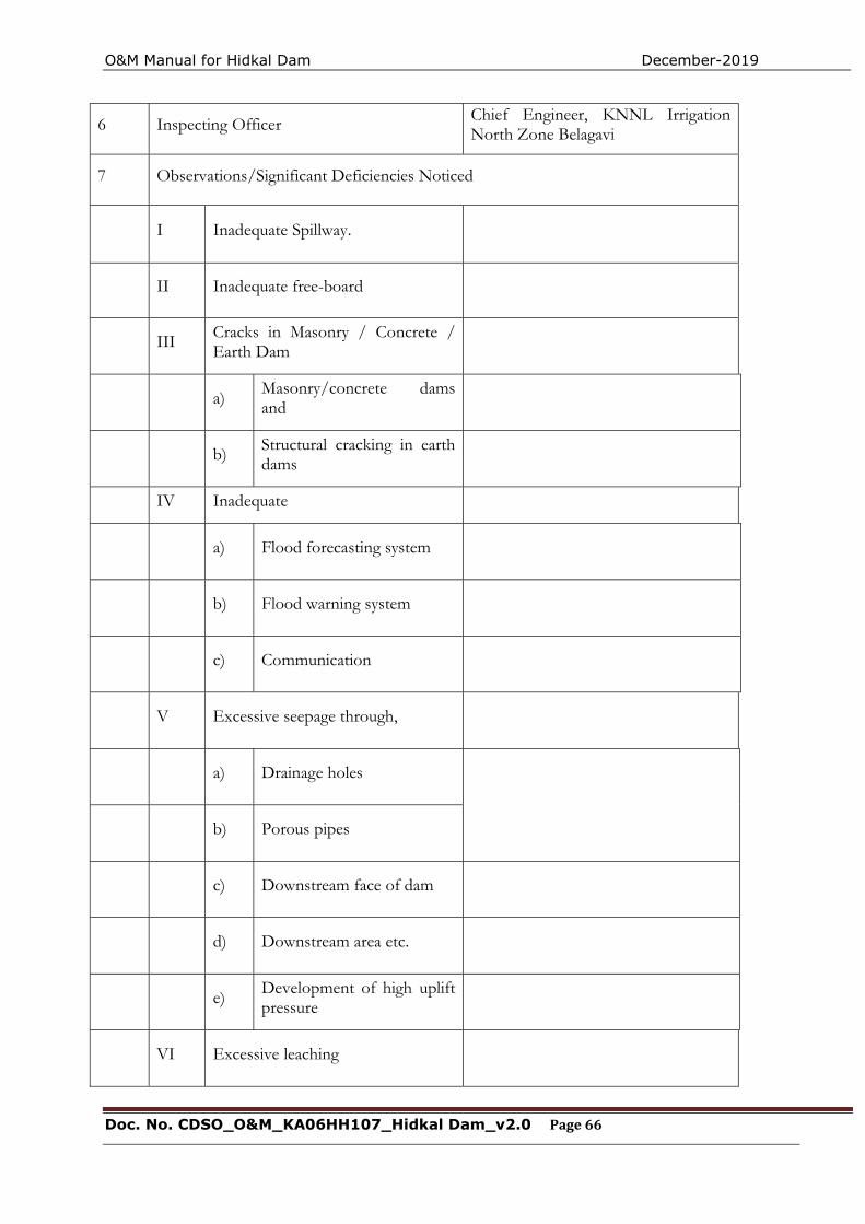
O&M Manual for Hidkal Dam December-2019
Doc. No. CDSO_O&M_KA06HH107_Hidkal Dam_v2.0 Page 66
6 Inspecting Officer Chief Engineer, KNNL Irrigation North Zone Belagavi
7 Observations/Significant Deficiencies Noticed
I Inadequate Spillway.
II Inadequate free-board
III Cracks in Masonry / Concrete / Earth Dam
a) Masonry/concrete dams and
b) Structural cracking in earth dams
IV Inadequate
a) Flood forecasting system
b) Flood warning system
c) Communication
V Excessive seepage through,
a) Drainage holes
b) Porous pipes
c) Downstream face of dam
d) Downstream area etc.
e) Development of high uplift pressure
VI Excessive leaching
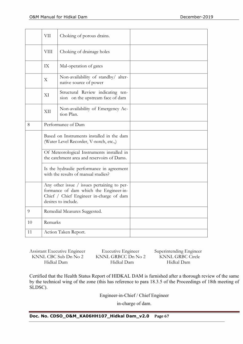
O&M Manual for Hidkal Dam December-2019
Doc. No. CDSO_O&M_KA06HH107_Hidkal Dam_v2.0 Page 67
VII Choking of porous drains.
VIII Choking of drainage holes
IX Mal-operation of gates
X Non-availability of standby/ alter-native source of power
XI Structural Review indicating ten-sion on the upstream face of dam
XII Non-availability of Emergency Ac-tion Plan.
8 Performance of Dam
Based on Instruments installed in the dam (Water Level Recorder, V-notch, etc.,)
Of Meteorological Instruments installed in the catchment area and reservoirs of Dams.
Is the hydraulic performance in agreement with the results of manual studies?
Any other issue / issues pertaining to per-formance of dam which the Engineer-in-Chief / Chief Engineer in-charge of dam desires to include.
9 Remedial Measures Suggested.
10 Remarks
11 Action Taken Report.
Assistant Executive Engineer Executive Engineer Superintending Engineer KNNL CBC Sub Dn No 2 KNNL GRBCC Dn No 2 KNNL GRBC Circle
Hidkal Dam Hidkal Dam Hidkal Dam
Certified that the Health Status Report of HIDKAL DAM is furnished after a thorough review of the same by the technical wing of the zone (this has reference to para 18.3.5 of the Proceedings of 18th meeting of SLDSC).
Engineer-in-Chief / Chief Engineer
in-charge of dam.

O&M Manual for Hidkal Dam December-2019
Doc. No. CDSO_O&M_KA06HH107_Hidkal Dam_v2.0 Page 68
THIS PAGE LEFT BLANK INTENTIONALLY
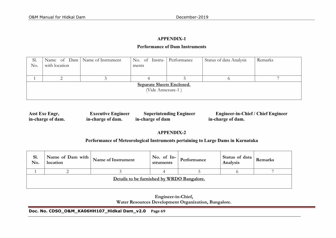
O&M Manual for Hidkal Dam December-2019
Doc. No. CDSO_O&M_KA06HH107_Hidkal Dam_v2.0 Page 69
APPENDIX-1
Performance of Dam Instruments
Sl.
No. Name of Dam with location
Name of Instrument No. of Instru-ments
Performance Status of data Analysis Remarks
1 2 3 4 5 6 7 Separate Sheets Enclosed.
(Vide Annexure-1 )
Asst Exe Engr, Executive Engineer Superintending Engineer Engineer-in-Chief / Chief Engineer in-charge of dam. in-charge of dam. in-charge of dam in-charge of dam.
APPENDIX-2
Performance of Meteorological Instruments pertaining to Large Dams in Karnataka
Sl. No.
Name of Dam with location Name of Instrument No. of In-
struments Performance Status of data Analysis Remarks
1 2 3 4 5 6 7
Details to be furnished by WRDO Bangalore.
Engineer-in-Chief,
Water Resources Development Organization, Bangalore.
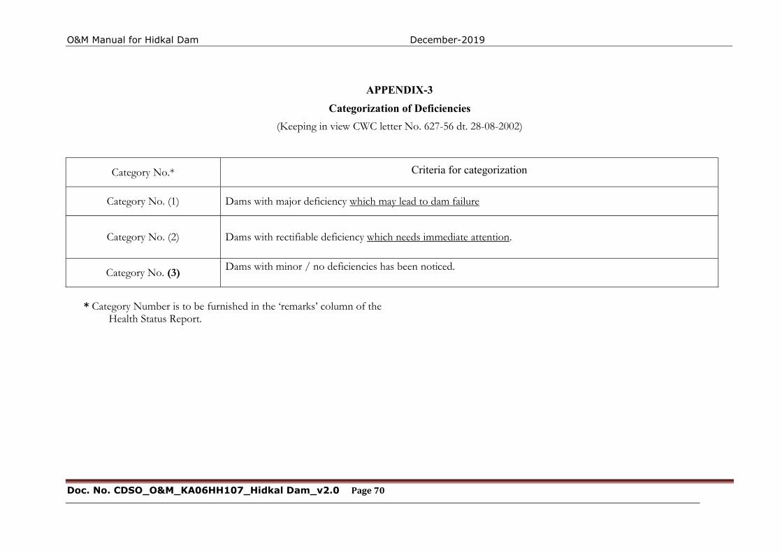
O&M Manual for Hidkal Dam December-2019
Doc. No. CDSO_O&M_KA06HH107_Hidkal Dam_v2.0 Page 70
APPENDIX-3
Categorization of Deficiencies
(Keeping in view CWC letter No. 627-56 dt. 28-08-2002)
Category No.* Criteria for categorization
Category No. (1) Dams with major deficiency which may lead to dam failure
Category No. (2) Dams with rectifiable deficiency which needs immediate attention.
Category No. (3) Dams with minor / no deficiencies has been noticed.
* Category Number is to be furnished in the ‘remarks’ column of the
Health Status Report.
O&M Manual for Hidkal Dam December-2019
Doc. No. CDSO_O&M_KA06HH107_Hidkal Dam_v2.0 Page 71
CHAPTER 4 - PROJECT MAINTENANCE
A good maintenance program protects Hidkal Dam against accelerating deterioration, prolongs its life, and greatly reduces the chance of failure. Nearly all the components of Hidkal Dam and its materials are susceptible to damage and deterioration if not well maintained. Moreover, the cost of a proper maintenance program is small compared to the costs of major repairs, loss of life and property and litigation. Preventative maintenance not only protects the dam and its owner but the public as well. If maintenance of a dam is neglected the consequences and costs will multiply.
Preventive maintenance assures that a dam and reservoir are in good working condition and prevents more harmful conditions from developing. Individual maintenance tasks are noted, with a description of the area where the maintenance is to be performed, the schedule for performing the tasks, and reporting procedures. Typical routine maintenance tasks performed includes mowing grass, removing vegetation, bushes and trees, removing litter and other debris, re-grading the crest and/or access roads, repairing fencing to keep livestock off the dam, etc. Other maintenance works that need to be performed on the embankment includes restoration of embankment to its design section, seepage problems, erosion, displaced riprap, cracking in embankment etc. In concrete / masonry dams there may be issues like cracking and disintegration in concrete, choking of drainage holes in dam body/ foundation, damages to spillway glacis/piers/energy dissipaters due to abrasion/ cavitation/unsymmetrical flows, damages to pointing on upstream & downstream faces of masonry dams, heavy seepages through some drains in foundation/inspection galleries etc.
A basic maintenance program has been developed primarily based on systematic and frequent inspections.
4.1 Maintenance Priorities
For Hidkal Dam, maintenance activities require to be prioriitized as immediate maintenance or preventative maintenance.
4.1.1 Immediate Maintenance
The following conditions are critical and call for immediate attention & reservoir lowering, if warranted. These conditions may include, but are not limited to:
The dam is about to be overtopped or being overtopped during high flood.
The dam is about to be breached by erosion, slope failure etc.
The dam showing signs of piping or internal erosion indicated by increasingly cloudy seepage or other symptoms.
The spillway being blocked or with some inoperable gates.
O&M Manual for Hidkal Dam December-2019
Doc. No. CDSO_O&M_KA06HH107_Hidkal Dam_v2.0 Page 72
Evidence of excessive seepage appearing anywhere on the dam site, e.g., the Embankment becomes saturated, defective water stops, etc., and seepage exiting on the downstream face is increasing in volume.
Although the remedy for some critical problems may be obvious (such as clearing a blocked spillway or repairing the spillway gates so that they are in working condition), the problems listed above generally demand the services of experienced engineers/expert panels familiar with the design, construction and maintenance of dams.
The emergency action plan (EAP) should be activated when any of the above conditions are noted. Note also that the “blue” conditions of the EAP are also applicable during con-trolled release of floods through the spillway.
4.1.2 Preventive Maintenance
This can be further classified as Condition based Maintenance and Routine Maintenance.
4.1.2.1 Condition Based Maintenance
The following maintenance should be completed as soon as possible after the defective condition is noted. These include but are not limited to:
Remove all vegetation and bushes from the dam and restoring any eroded areas and to establish a good grass cover.
Fill animal burrows. Restore and reseed eroded areas and gullies on embankment. Repair of defective gates, valves, and other hydro-mechanical equipment. Repair any concrete or metal components that have deteriorated. Cleaning of the choked drainage holes in the dam body/ foundations in concrete /
masonry dams. Repair any damages on spillway glacis, piers, energy dissipaters, training/divide walls,
downstream areas etc. Repairs on the upstream face of masonry dams, in case the pointing is damaged, due to
which there is increased seepage. Controlling any heavy seepage in the foundation/ inspection galleries in
Concrete/Masonry dams from drainage holes. Repairs of any cracks/cavities/joints in concrete/masonry dams/structures.
However, many of these works will require the services of experienced engineers/expert panels.
4.1.2.2 Routine Maintenance
Several tasks should be performed on a continuous basis. These include but are not limited to the following:
Routine mowing, restore and reseed eroded areas and gullies on downstream face of the left flank embankment and general maintenance including repairs/cleaning of surface drains on downstream face and in the downstream area.
Maintenance and treatment of any cracks/joints/ cavities in Concrete/Masonry dams and spillways based on the recommendations of experienced engineers / expert panels.
Observation of any springs or seepage areas, comparing quantity and quality (clarity) with prior observations in the embankment.
O&M Manual for Hidkal Dam December-2019
Doc. No. CDSO_O&M_KA06HH107_Hidkal Dam_v2.0 Page 73
Monitoring of downstream development which could have an impact on the dam and its hazard category.
Maintenance of Electrical & Hydro-Mechanical equipment and systems e. g. Servicing of spillway gates & stop logs, hoisting arrangements, gantry crane, gates/hoist of outlet works/sluices & stand by generator.
Maintaining proper lighting at dam top, galleries, etc. Monitoring of seepage in galleries. Monitoring/ cleaning & removal of leached deposits in porous concrete / formed drains
in dam body and foundation drainage holes. Maintenance of all dam roads & access roads. Operation of electrical and mechanical equipment and systems including exercising gates
& valves. To keep the gate slots clear of silt/debris. Maintenance/testing of monitoring equipment (instruments) and safety alarms. Testing of security equipment. Testing of communication equipment. Any other maintenance considered necessary.
4.2 Procedures for Routine Maintenance
The O&M Manual includes detailed instructions and schedules for performing periodic maintenance works at the site. This includes maintenance of the dam, the appurtenant works, and the reservoir areas. Methodology / Specifications for carrying out maintenance works of general & recurring nature should be included in the Manual.
Dam repairs are scheduled based on severity of the problem, available resources, and weather conditions. For example, if a severe settlement problem (more than envisaged in designs) or cracking is detected on the crest of the dam, it should have a high priority since further degradation could lead to dam breaching. The causes of all major issues / problems should be identified and evaluated by experienced engineers/ Expert Panels so that appropriate remedial measures can be finalized. Correcting minor rill erosion on the downstream slope could be assigned a low priority since it is not a dam safety concern. This type of repair will also be weather dependent, since grass can only be planted during specific times of the year, and the embankment should be dry so that more damage is not inflicted to the embankment slopes.
4.2.1 Earthwork
The surfaces of an earthen dam may deteriorate due to several reasons. For example, wave action may cut into the upstream slope, vehicles may cause ruts in the crest or slopes, trails left by livestock can result in erosion, or runoff waters may leave erosion gullies on the downstream slope. Other special problems, such as shrinkage cracks or rodent damage, may also occur. Damage of this nature must be repaired constantly.
The maintenance procedures described here are effective in repairing minor earthwork problems. However, this section is not intended to be a technical guide, and the methods discussed should not be used to solve serious problems. Conditions such as embankment slides, structural cracking, and sinkholes threaten the immediate safety of a dam and require immediate repair under the directions of experienced engineers/Expert panels.
The material selected for repairing embankments should be free from vegetation, organic materials, trash, and large rocks.
If flow-resistant portions such as the core of an embankment dam are being repaired, materials that are high in clay or silt content should be used. If the area is to be free draining or highly
O&M Manual for Hidkal Dam December-2019
Doc. No. CDSO_O&M_KA06HH107_Hidkal Dam_v2.0 Page 74
permeable (such as pervious shell of an embankment dam) the material should have a higher percentage of sand and gravel. It is usually satisfactory to replace or repair damaged areas with soils like those originally in place.
An important soil property affecting compaction is moisture content. Soils that are too dry or too wet do not compact well. One may test repair material by squeezing it into a tight ball. If the sample keeps its shape without cracking and falling apart (which means it is too dry), and without depositing excess water onto the hand (which means it is too wet), the moisture content is near the proper level.
Before placement of earth, the repair area needs to be prepared by removing all inappropriate material. All vegetation, such as bushes, roots, and tree stumps, along with any large rocks or trash need to be removed. Also, unsuitable earth, such as organic or loose soils, should be removed, so that the work surface consists of exposed, firm, clean embankment material.
Following cleanup, shape and dress the affected area so that the new fill can be placed and compacted in horizontal lifts to the level specified in the technical specifications. Also it must be properly keyed (benched) with the existing material for which proper construction practices ae carried out to “knit” the new fill in to the existing soils to ensure proper bonding. This can be accomplished by using the following simple procedures
1. Scarify the existing soil layer
2. Place new moisturized soils in loose layers up to 20 centimeters thick
3. Compact to required density at optimum moisture content (OMC)
4. Scarify compacted layer 10 centimeters
5. Moisturize the layer before placement of soils
6. Compact
7. Continue process until lines and grades are accomplished. Overbuild can be trimmed back to design lines and grades
8. Seed of turf the fill to minimize erosion processes
9. Water routinely to ensure turf root system is fully developed.
Erosion is one of the most common maintenance problems at embankment structures. Erosion is a natural process and its continuous forces will eventually wear down almost any surface or structure. Periodic and prompt maintenance is essential to prevent continuous deterioration and possible failure. Turfing, free from weeds and deleterious materials, is an effective means of preventing erosion. Rills and gullies should be filled with suitable soil, compacted, and then seeded or turfed as necessary. Large eroded gullies can be slowed by stacking bales of hay or straw across the gully until permanent repairs can be made.
Erosion is also common at the point where an embankment and the concrete walls of a spillway or other structure meet. Poor compaction adjacent to such walls during construction and later settlement can result in an area along the wall that is lower than the grade of the embankment. People often walk along these walls, wearing down the vegetative cover. Workable solutions include re-grading the area so that it slopes away from the wall, adding more resistant surface protection, or constructing steps. Steps can be provided / constructed at regular intervals along the length of the dam for going from downstream toe to the dam top. All vehicular traffic, except for maintenance, should be restricted from the dam.
Paths due to pedestrian, livestock, or vehicular traffic (two and four-wheeled) are a problem on many embankments. If a path has become established, vegetation will not provide adequate

O&M Manual for Hidkal Dam December-2019
Doc. No. CDSO_O&M_KA06HH107_Hidkal Dam_v2.0 Page 75
Photo 4 – View of rehabilitated upstream riprap. Repair of any noted settlement to be taken up as
necessary.
protection and more durable cover will be required unless traffic is eliminated. Stones may be used effectively to cover such footpaths.
Runoff often concentrates along embankment slopes where the hinge point on the crest is lower than the surrounding crest and runoff ponds in these low areas. The concentrated runoff flows down the slope cutting the soils and forming rills and gullies resulting in loss of design lines and grades and affecting stability of the structure.
Upstream Riprap
The upstream face is protected against wave erosion. Rip-rap is provided for the purpose with filter layers below.
Nonetheless, erosion can still occur in existing riprap. Water running down the slope under the riprap can erode the finer filter materials under the riprap and soils leaving voids and loss of grade. Wave runoff will also undermine the filter layer especially along the full reservoir level and over time wash out finer material. This can be checked through observance of linear embankment settlement. Sections of riprap that have slumped downward are often signs of this kind of erosion. When erosion occurs on the upstream slope of a dam, repairs should be made as soon as possible. Repairs can be made following the same design details as provided in the embankment section. proper preparation of the surfaces of the existing embankment as described in the earlier paragraph for placement and compaction of embankment. Please refer to IS 8237- Code of practice for protection of Slopes for Reservoir Embankments is recommended to be reviewed and followed for carrying out this repair work.
Controlling Vegetation
Keep the entire dam clear of unwanted vegetation such as bushes or trees. Excessive growth may cause several problems:
It can obscure the surface of an embankment and not allow proper inspection of the dam.
Large trees can be uprooted by high wind or erosion and leave large voids that can lead to breaching of the dam.
Some root systems can decay and rot, creating passageways for water, leading topping erosion.
Growing root systems can lift concrete slabs or structures.
Rodent habitats can develop undetected.
All bushes/trees should be as far as possible removed by root to prevent re-growth. The resulting voids must be backfilled with suitable, well-compacted soils. It is recommended to remove the plants/vegetation at their early stage to prevent or minimize their growing into big trees/bushes, etc. In cases where trees and bushes cannot be removed, the root systems should
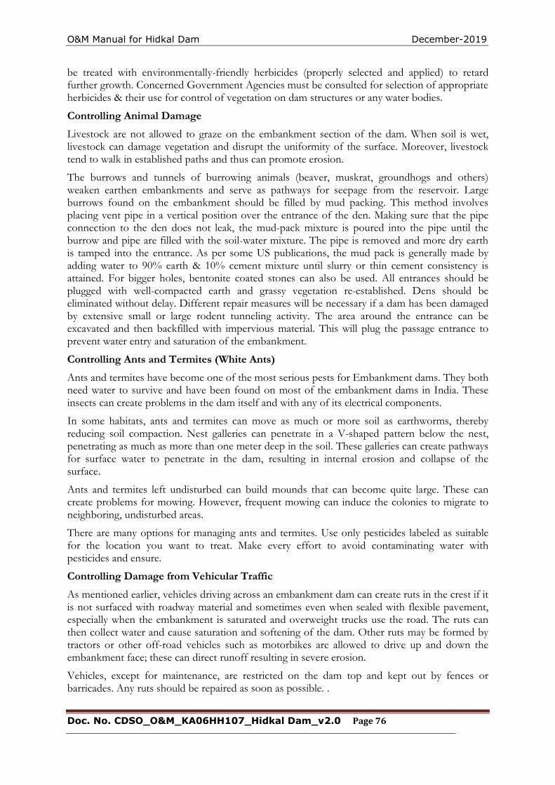
O&M Manual for Hidkal Dam December-2019
Doc. No. CDSO_O&M_KA06HH107_Hidkal Dam_v2.0 Page 76
be treated with environmentally-friendly herbicides (properly selected and applied) to retard further growth. Concerned Government Agencies must be consulted for selection of appropriate herbicides & their use for control of vegetation on dam structures or any water bodies.
Controlling Animal Damage
Livestock are not allowed to graze on the embankment section of the dam. When soil is wet, livestock can damage vegetation and disrupt the uniformity of the surface. Moreover, livestock tend to walk in established paths and thus can promote erosion.
The burrows and tunnels of burrowing animals (beaver, muskrat, groundhogs and others) weaken earthen embankments and serve as pathways for seepage from the reservoir. Large burrows found on the embankment should be filled by mud packing. This method involves placing vent pipe in a vertical position over the entrance of the den. Making sure that the pipe connection to the den does not leak, the mud-pack mixture is poured into the pipe until the burrow and pipe are filled with the soil-water mixture. The pipe is removed and more dry earth is tamped into the entrance. As per some US publications, the mud pack is generally made by adding water to 90% earth & 10% cement mixture until slurry or thin cement consistency is attained. For bigger holes, bentonite coated stones can also be used. All entrances should be plugged with well-compacted earth and grassy vegetation re-established. Dens should be eliminated without delay. Different repair measures will be necessary if a dam has been damaged by extensive small or large rodent tunneling activity. The area around the entrance can be excavated and then backfilled with impervious material. This will plug the passage entrance to prevent water entry and saturation of the embankment.
Controlling Ants and Termites (White Ants)
Ants and termites have become one of the most serious pests for Embankment dams. They both need water to survive and have been found on most of the embankment dams in India. These insects can create problems in the dam itself and with any of its electrical components.
In some habitats, ants and termites can move as much or more soil as earthworms, thereby reducing soil compaction. Nest galleries can penetrate in a V-shaped pattern below the nest, penetrating as much as more than one meter deep in the soil. These galleries can create pathways for surface water to penetrate in the dam, resulting in internal erosion and collapse of the surface.
Ants and termites left undisturbed can build mounds that can become quite large. These can create problems for mowing. However, frequent mowing can induce the colonies to migrate to neighboring, undisturbed areas.
There are many options for managing ants and termites. Use only pesticides labeled as suitable for the location you want to treat. Make every effort to avoid contaminating water with pesticides and ensure.
Controlling Damage from Vehicular Traffic
As mentioned earlier, vehicles driving across an embankment dam can create ruts in the crest if it is not surfaced with roadway material and sometimes even when sealed with flexible pavement, especially when the embankment is saturated and overweight trucks use the road. The ruts can then collect water and cause saturation and softening of the dam. Other ruts may be formed by tractors or other off-road vehicles such as motorbikes are allowed to drive up and down the embankment face; these can direct runoff resulting in severe erosion.
Vehicles, except for maintenance, are restricted on the dam top and kept out by fences or barricades. Any ruts should be repaired as soon as possible. .
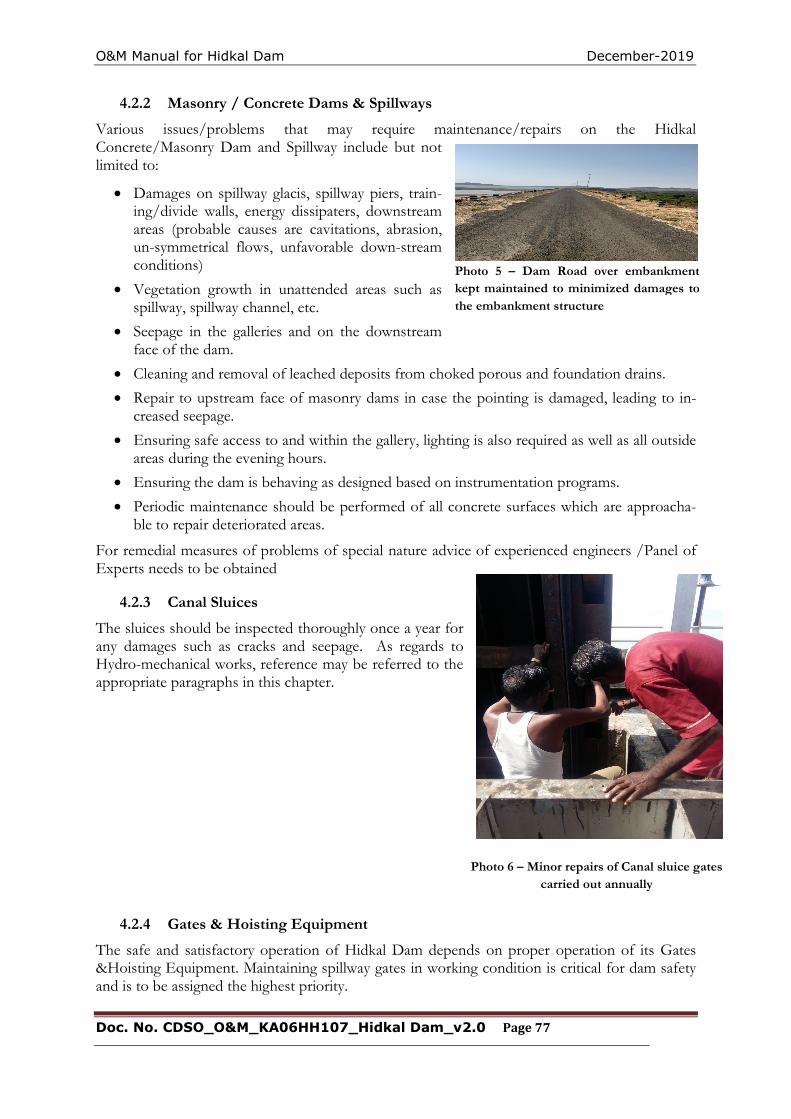
O&M Manual for Hidkal Dam December-2019
Doc. No. CDSO_O&M_KA06HH107_Hidkal Dam_v2.0 Page 77
Photo 5 – Dam Road over embankment kept maintained to minimized damages to the embankment structure
Photo 6 – Minor repairs of Canal sluice gates carried out annually
4.2.2 Masonry / Concrete Dams & Spillways
Various issues/problems that may require maintenance/repairs on the Hidkal Concrete/Masonry Dam and Spillway include but not limited to:
Damages on spillway glacis, spillway piers, train-ing/divide walls, energy dissipaters, downstream areas (probable causes are cavitations, abrasion, un-symmetrical flows, unfavorable down-stream conditions)
Vegetation growth in unattended areas such as spillway, spillway channel, etc.
Seepage in the galleries and on the downstream face of the dam.
Cleaning and removal of leached deposits from choked porous and foundation drains.
Repair to upstream face of masonry dams in case the pointing is damaged, leading to in-creased seepage.
Ensuring safe access to and within the gallery, lighting is also required as well as all outside areas during the evening hours.
Ensuring the dam is behaving as designed based on instrumentation programs.
Periodic maintenance should be performed of all concrete surfaces which are approacha-ble to repair deteriorated areas.
For remedial measures of problems of special nature advice of experienced engineers /Panel of Experts needs to be obtained
4.2.3 Canal Sluices
The sluices should be inspected thoroughly once a year for any damages such as cracks and seepage. As regards to Hydro-mechanical works, reference may be referred to the appropriate paragraphs in this chapter.
4.2.4 Gates & Hoisting Equipment
The safe and satisfactory operation of Hidkal Dam depends on proper operation of its Gates &Hoisting Equipment. Maintaining spillway gates in working condition is critical for dam safety and is to be assigned the highest priority.
O&M Manual for Hidkal Dam December-2019
Doc. No. CDSO_O&M_KA06HH107_Hidkal Dam_v2.0 Page 78
If routine inspection of the Hydro-Mechanical Equipment shows the need for maintenance, the work should be completed as soon as possible. The simplest procedure to ensure smooth operation of gates is to operate them through their full range at least once, and preferably twice annually (before monsoon & after monsoon keeping a gap of at least six months). Because operating gates under full reservoir pressure can result in large discharges, exercising of gates should preferably be carried out during dry conditions or lean times of the year using the stop-logs/ emergency gates.
Commonly used Gates and Hoists including their inspection / maintenance requirements are discussed below.
The aspects to be inspected and maintained periodically for ensuring proper operation of these gates are as under:
i) The gate slot and bottom platform/sill beam should be cleaned periodically. Scales formed over the embedded parts should be removed. Second-stage concrete should be checked for any development of cracks / leakages and repairs should be attended to immediately.
ii) The gate leaf should be thoroughly cleaned and repainted as and when necessary according to the procedure or guidelines- indicated in IS: 14177 or as per the recommendations of the paint manufacturer. All drain holes provided in the gate assembly should be cleaned.
iii) Rubber seals should be smoothed, if required, for proper alignment. All nuts and bolts fixing the seal to the gate should be tightened uniformly to required torques. Seals, if found damaged or found leaking excessively should be adjusted, repaired or replaced as considered necessary.
iv) The wheel shall be rotated to check their free movement. Gate roller bearings and guide roller bushes should be properly lubricated. Whenever necessary these should be opened for rectifications of defects, cleaning and lubrication and should thereafter be refitted. These may be replaced if repairs are not possible.
v) Hoisting connection of the gate leaf should be lubricated where necessary and defects if any should be rectified.
vi) All nuts, bolts, check nuts and cotter pins of the lifting devices should be checked periodically.
vii) All components should be greased and lubricated. Recommended and approved oils and grease only should be used.
viii) Roller assembly should be adjusted by the eccentricity arrangement to ensure all rollers rest uniformly on the track plates particularly in the closed position of the gate.
ix) Where filling valves are provided as part of the gate structure, all the nuts, bolts, check nuts etc. should be tightened.
x) All welds shall be checked for cracks/ damages. Any weld that might have become defective should be chipped out and redone following the relevant code provisions. Damaged nuts, bolts, rivets, screws etc. should be replaced without delay.
xi) The filling-in valves allow passage of water when it is lifted by lifting beam & crane due to creation of space between stem seat and exit passage liner. The springs and associated components should be checked periodically for damages and replaced if necessary.
O&M Manual for Hidkal Dam December-2019
Doc. No. CDSO_O&M_KA06HH107_Hidkal Dam_v2.0 Page 79
xii) The guide-assemblies, wheel-assemblies and sealing-assemblies shall be cleared off grit, sand or any other foreign material.
xiii) The wheel pin shall be coated with corrosion resistant compound.
xiv) All nuts and bolts shall be tightened.
The aspects to be inspected and maintained periodically for ensuring proper operation of these gates are as under :
a) Rubber Seals:
i) Seals shall be inspected for leakages. Locations of excessive leakages shall be recorded for taking remedial measures. Weeping or slight flow in localized area will not require immediate remedial measures. However, measures like tightening of bolts are carried out. Further adjustment is carried out during annual maintenance.
ii) If leakage is excessive & immediate repair is considered necessary, the stop log gates shall be dropped and seals repaired or replaced.
NOTE: - During monsoon period, stop log gates shall NEVER be lowered in spite of heavy leakage through seals.
b) Trunnion block assembly and anchorages:
(i) All the nuts and bolts of Trunnion block assembly and its anchorages shall be checked for tightness.
(ii) Check all the welds for soundness and rectify defects.
(iii) Check whether the Yoke girder and thrust block is covered on not. If not, cover it with mild steel plates.
(iv) Cover the trunnion pin with anti- corrosive jelly.
(v) Remove all dirt, grit etc. from trunnion assembly and lubricate trunnion bearings of the gate with suitable water resisting grease as recommended by bearing manufacturers.
c) Gate structures:
i) Check all the welds for soundness and rectify defects.
ii) Check welds between arms and horizontal girders as well as between latching bracket and skin plate with the help of magnifying glass for cracks/defects and rectify the defects.
iii) Clean all drain holes including those in end arms and horizontal girders.
iv) Check all the nuts and bolts and tighten them. Replace damaged ones.
v) Check upstream face of skin plate for pitting, scaling and corrosion. Scaling may be filled with weld and grinded. Corroded surface shall be cleaned and painted.
d) Embedded Parts:
i) All the sill beams and wall plates shall be inspected for crack, pitting etc. and defects shall be rectified.
ii) The guide roller pins shall be lubricated.
e) General Maintenance:
i) Defective welding should be chipped out and it should be re-welded duly following the relevant codal provision (IS: 10096, Part-3).
O&M Manual for Hidkal Dam December-2019
Doc. No. CDSO_O&M_KA06HH107_Hidkal Dam_v2.0 Page 80
ii) Damaged nuts, bolts, rivets, screws etc. should be replaced.
iii) Any pitting should be filled up by welding and finished by grinding if necessary.
iv) The gate leaf, exposed embedded metal parts, hoists and hoist supporting structure etc., should be thoroughly cleaned and repainted when required keeping in view the original painting system adopted and as per the guidelines contained in IS: 14177.
v) Trunnion bearing should be greased as and when required. Keeping trunnion bearings in perfect working condition is very important. All other bolted connections should also be checked up for proper tightness.
vi) Bolts and trunnion bearing housing should be tightened wherever required.
vii) The seals of the gate should be checked for wear and tear and deterioration. These should be adjusted/replaced as and when necessary.
viii) The wall plates, sill beams shall be checked and repaired if necessary.
ix) Wire ropes should be properly lubricated.
x) Oil level in the worm reduction unit should be maintained by suitable replenishment. Oil seals should also be replaced if required. Lubrication of other parts of hoists such as chains, position indicators and limit switches should also be done.
xi) The stroke of the brake should be reset to compensate for lining wear. Worn out brake linings should be replaced in time.
xii) Flexible couplings should be adjusted if required.
xiii) Repairs and replacements of all electrical relays and controls should be attended to.
xiv) Maintenance of alternative sources of Power such as Diesel Generating sets and alternative drives wherever provided should be carried out.
xv) The list of essential spare parts to be kept available should be reviewed and updated periodically. The condition of spares should be checked periodically and protective coating given for use.
4.2.5 Electrically operated fixed hoists
1. General Instructions:
a) Operation of fixed hoist without lifting the gate is not possible and need not therefore be attempted. It will be possible to operate the unit and observe operation of load carrying hoist component when gate is being lifted or lowered.
b) Never open any bolt or nut on motor, gear boxes, rope drums and other load carrying hoist components when the gate is in raised position. The gate should be fully closed or rested on the gate latches before carrying out any work on hoist components including motor brake and other electrical equipment.
c) The aspects to be inspected and maintained periodically for ensuring proper operation of Rope drum hoists are as under;
i. Entrance to all hoist platforms shall be kept locked. All keys shall remain with the shift supervisor.
O&M Manual for Hidkal Dam December-2019
Doc. No. CDSO_O&M_KA06HH107_Hidkal Dam_v2.0 Page 81
ii. A cursory daily inspection shall be made of hoist and gate to ensure that there is no unusual happening.
iii. Clean all hoisting equipment and hoist platform.
iv. Check oil level in gearboxes and replenish as and when required with oil of proper grade.
v. Apply grease of suitable grade by grease gun.
vi. Lubricate all bearings, bushings, pins, linkages etc.
vii. Check all the fuses on the power lines.
viii. All bolts and nuts on gear boxes, hoist drum and shaft couplings should be checked for tightness.
ix. Check the supply voltage.
x. Drain sample gear oil from each of the gear boxes. If excessive foreign particles or sludge is found, the gear box shall be drained, flushed and filled with new oil.
xi. All the geared couplings shall be greased.
xiii. Raise and lower the gate by hoist motor and check for smooth, and trouble free operation of gate without excessive vibration.
xiv. Observe current drawn by motor at the time of lifting and check if it is more than normal. If so, stop the hoist and investigate the cause and rectify.
xv. Check the condition of painting of various components and remove rust wherever noticed and repaint the portion after proper cleaning as per painting schedule.
xvi. All trash, sediments and any other foreign material shall be cleared off the lifting rope and lifting attachment.
xvii. All ropes shall be checked for wear and tear and if broken wires are noticed, the rope shall be replaced.
xviii. All the wire ropes shall be checked and all visible oxidation shall be removed.
xix. All wire ropes shall be greased with cardium compound.
xx. Check the overload relays for proper functioning.
xxi. Check all the nuts, bolts, rivets, welds and structural components for hoisting platform and its supporting structure for wear, tear and damage. All damages shall be rectified. All bolts shall be tightened. The portion with damaged painting shall be touched up.
xxii. Check the pulleys, sheaves and turn-buckles.
xxiii. Raise and lower the gate for its full lift several time (at least three to four) and observe the following:
O&M Manual for Hidkal Dam December-2019
Doc. No. CDSO_O&M_KA06HH107_Hidkal Dam_v2.0 Page 82
a) Check the limit switches and adjust for design limits.
b) The effectiveness and slip of the breaks shall be checked by stopping the gate in raising and lowering operations. The brakes shall be adjusted if needed.
c) When the gate is operated, there should not be any noise or chatter in the gears.
xxiv. Adjust the rope tension of wires if unequal.
xxv. Check for all gears and pinions for uneven wear and adjust for proper contact. Grease the gears.
xxvi. Repaint the hoist components, hoisting platform and its supporting structures as per requirement.
xxvii. The periodic maintenance of commercial equipment like motors, brakes, thrusts etc. shall be carried out as per manufacturers operation and maintenance manual.
4.3. Maintenance of Electrical components of Fixed Rope Drum Hoists:
a). The electrical components to be inspected and maintained periodically are as under;
i) Starters should be cleaned free of moisture and dust.
ii) Each individual contactor should be tried by hand to make sure that it operates freely.
iii) All wearing parts should be examined in order to take note of any wear which may have occurred during operation.
iv) If the contactor hums, the contact faces should be cleaned.
(v) Examine all connections to see that no wires are broken and no connections are loose.
vi) Clean the surface of the moving armature and magnet core which comes together when the contactor closes, free of dust or grease of any kind.
vii) Examine the mechanical interlocks between the reversing contactor and see when the contact tips of one of the contactor units are touching, it is impossible to get the contact tips of the other unit to touch.
viii) The contact tips should be kept free from burns or pits by smoothening with fine sand paper or emery paper.
ix) Replace the contact tips which have worn away half-way.
x) Do not lubricate the contacts.
xi) Blow out windings thoroughly by clean and dry air to clear air passage in the stator and the rotor of any accumulated dirt. The air pressure shall not be too high to damage the insulation.
xii) Examine earth connections and motor leads.
xiii) Examine motor windings for overheating
xiv) Examine control equipment’s
xv) Examine starting equipment for burnt contacts
xvi) Check and tighten all nuts and bolts
O&M Manual for Hidkal Dam December-2019
Doc. No. CDSO_O&M_KA06HH107_Hidkal Dam_v2.0 Page 83
xvii)Clean and tighten all terminals and screw connections all contact surfaces shall be made clean and smooth.
xviii)Lubricate the bearings
xix) Overhaul the controllers
xx) Inspect and clean circuit breakers.
xxi) Wipe brush holders and check bedding of brushes.
xxii) Blow out windings thoroughly by clean and dry air. The pressure shall not be so high that insulation may get damaged.
xxiii) Check the insulation resistance of the motor between any terminal and the frame. If the measured resistance is less than the prescribed value, then steps shall be taken to dry- out the motors either by
passing a low voltage current through the windings or by placing the stator and rotor only in a warm dry place for a day or so.
WARNING: The complete motor shall never be put in an oven for drying as that may melt the grease out of bearings.
xxiv) Coat the windings with an approved high temperature resisting insulation enamel or varnish.
xxv) Over haul the motor, if required.
xxvi) Check the switch fuse units and renew, if required.
xxvii) Check resistance or earth connections.
xxviii) Check air gap.
b) Solenoid Operated Brakes
i) All fixing bolts shall be checked and tightened at least once in three months.
ii) The magnet stroke should be reset to compensate for wear.
iii) Re-adjust the brake when the magnet stroke reaches the value given on the instruction plate.
iv) Brake lining should be checked and replaced when required.
v) Examine all electrical leads and connections.
vi) Rubber bushes or couplings should be checked and replaced if defective.
vii) The pins should be tightened.
viii) Brake drum shall be cleaned to remove any dust or grease.
Stop logs, lifting beam & gantry crane
1.4 Spillway Stoplogs, Lifting Beam &Radial Gate
4.3.1 MAINTENANCE OF STOPLOGS a. Regular Maintenance
1. For gear and pinion, grease or lubricating compound shall be frequently used for the smooth operation
2. Wire Rope should be kept lubricated on regular basis with cadmium compound.
3. Damaged nuts, bolts etc. should be replaced
4. Oil level in the gear box and worm reducer should maintained.
O&M Manual for Hidkal Dam December-2019
Doc. No. CDSO_O&M_KA06HH107_Hidkal Dam_v2.0 Page 84
5. Electromagnetic brake should be checked regularly and plunger to be cleaned dry to ensure proper functioning. The break shop to be cleaned.
b. Periodical Maintenance
1. Wire Rope should be examined for rusting, broken strands etc. and the wire rope at both the ends of the gate should have equal initial tension.
2. All nuts, bolts and screws shall be checked for wear, tear and tightness
3. Drain oil from gear box once in every 6 months and replace with relevant grade.
4. Ensure proper meshing of gear and pinion.
5. Location and adjustment of guide shoe should be checked.
6. Check E.M. Brake and thruster brake properly functioning.
7. All the moving parts should be properly lubricated.
8. The fuses are to be checked and replaced when they are worn-out. Replacements of fuses are necessary when they emit smell or get over heated. Care should be taken to select the correct size of fuses.
A. MAINTENANCE GANTRY CRANE
Hoisting trolley of the Gantry cranes is built on top of a wheeled mobile gantry structure travel-ling over fixed rails and is used to straddle an object or load over a workspace.
Following aspects need to be considered and attended to during maintenance;
1. Oil level in the gear boxes. It is very important to ensure that the correct oil level is maintained. Over filling causes overheating and leakage, therefore, care should be taken that the breather holes are not clogged by any foreign material like dust, paint etc.
2. The insulation resistance of motor windings. In case it is found to have dropped below a prescribed value, the motor should be dried prior to putting back in service. If weak insulation becomes a regular feature, the winding should be given a good coat of insulating varnish after the motor has been dried.
3. Checking of all the electrical connections.
4. Lubrication of each part of crane
5. Removal of any loose/foreign material along the rail track
6. Actuating tests of limit switches
7. Actuating tests of brakes.
8. All fuses in the control panel should be checked and if necessary, it should be replaced.
9. Necessary terminal connections of motors, brakes etc. is to be checked.
10. Overload relay should be checked.
O&M Manual for Hidkal Dam December-2019
Doc. No. CDSO_O&M_KA06HH107_Hidkal Dam_v2.0 Page 85
11. Visual inspection of wire ropes for any snapped loose wire and its proper lubrication.
12. Checking of rope clamps on the drum and tightening of bolts if required.
13. Gearbox assembly should not have any leakage of oil.
14. Unusual noise/vibration if any should be checked and rectified before operation.
B. MAINTENANCE OF MOTOR
Motors shall be blown out at regularly intervals to keep its ventilating passage clear, particularly when operating in dirty atmosphere.
Moisture, oil, dirt, grease and carbon or metallic dust are the principal causes of break down. The motor therefore be kept clean and dry and must be kept free from oil and greases, damp and dirt, periodical cleaning with dry compressed air with a brush is necessary.
The motor required be examining and dismantling from time to time and frequency of service cleaning will depend upon the conditions under which the motor operates. During periodical cleaning care shall be taken to clean air passage in the starter and motor of any accumulated dirt.
Terminals and screw connections shall be kept clean and tight. If they become dirty or corroded, they shall be disconnected and all contact surfaces made clean and smooth. Bad contact leads to sparking and ultimate breakdown.
C. LUBRICATION AND MAINTENANCE OF REDUCTION GEAR UNIT
1.Satisfactory performance of grease required that the lubricating oil kept be clean, and free from dirt, grit, moisture and sludge. Depending upon operating conditions the oil eventually becomes contaminated and should be drained periodically. During operation the oil level should be peri-odically chcked, too high-level results loss of power and oil leakage, too low oil results in fric-tion in bearings and on gear teeth causing overheating. Use proper graded oil.
2. Oil level should be checked with the help of dipstick or the oil indicator and should be topped up, if necessary.
3. Where the bearings of the unit are greases lubricated, the same should be filled with the top of grease gun.
4. Care should be taken that the breather holes are not clogged by any foreign materials, like dust, paint etc.
5. During cleaning gear casing should be flushed with the same sort oil that is used under work-ing Conditions. If encasing is opened for cleaning all sealing compound must be removed.
O&M Manual for Hidkal Dam December-2019
Doc. No. CDSO_O&M_KA06HH107_Hidkal Dam_v2.0 Page 86
D. LUBRICATION CHART PART LUBRICATION FOR FREQUENCY
1. Hoist Brake Hand oiled points One in a month
Fulcrum pins
2. Long travel Hand oiled points One in a month
Brake fulcrum
Pins
3. Motors:
Hoist Long travel End Bearing Replace once in six
Months and renew
Once in a year.
4. Long travel Grease Nipples Repack once in Six
Shaft Plummer Blocks Months and renew
Once in a year.
5. Gear Boxes Gear Boxes Check oil level once
A month and top up
As necessary.
6. Pinion & Gear Gears & Pinions Every 3 Months.
Wheels
7. Wire Rope Full Wire (Cardium Every year preferably
Compound) before onset of Monsoon
E. MAINTENANCE OF BEARING
Like all other important machine components ball and roller bearings must occasionally be cleaned and examined.
In many cases it is permissible to let the bearing run for considerable / longer time before carry-ing out inspections, especially the conditions of the bearings can be ascertained, during service for example, by listening to the sound produced during running, checking the temperature of noting the colour of the lubricant.
While spirit good quality paraffin, petrol or benzene may be recommended as suitable for clean-ing roller bearings.
Bearing should not be allowed to stand dry for any length of time after they have cleaned out, should be oiled and greased immediately when this is done, the bearings should be rotated sever-al times to that oil or grease can reach all vital parts and thereby protect the bearings from rust.
For sheaves, oiling the bearing at frequent interval and checking that they rotate freely must be done. A seized-up sheave may ruin a rope very speedily. Care should be taken to see that the rope does not foul in flat against any obstacle in its way.
O&M Manual for Hidkal Dam December-2019
Doc. No. CDSO_O&M_KA06HH107_Hidkal Dam_v2.0 Page 87
F. MAINTENANCE OF WIRE ROPE
Frequently the inspection of the entire length of rope is necessary. Watch constantly for broken wires, excessive wear and lubrication, see that the number of broken wires does not exceed as laid down in different regulation.
Prompt attention must be given to a broken wire in a rope otherwise damage to other wires and serious accidents may results.
Cleaning wire rope with brush or compressed air and giving it a light coating of special wire rope dressing is essential. This lubricant puts a protective film on each individual wire, repels water and stops corrosion.
G. CHECK FOR THE TIGHTNESS OF THE BOLTS
1. Fixing bolts of motor and reduction gears.
2. Plummer Block base Bolts.
3. Bolts of all Coupling.
4. Inspect the keys in the Couplings for its correct position once in every six months.
5. The wire Rope and is fixed over the winding drum by weans of clamps and bolts. These are to be checked for its tightness periodically.
4.3.2 ADDITIONAL MAINTENANCE ITEMS FOR STOPLOGS
The stop log units being in pieces, the top non-interchangeable unit with unique features as well as the other interchangeable units are stored in the grooves in various spans / bays. The follow-ing aspects are to be considered and attended to during maintenance:
1. Defective / damaged / cracked welding should be cutout and re-welded.
2. Damaged nuts, bolts, screws etc. should be replaced.
3. The gate leaf should be thoroughly cleaned and repainted whenever necessary
4. Rubber seals should be ground, if required to bring it in to alignment. All nuts and bolts for fixing seals to gate should be tightened uniformly. Seals when damaged or found leaking excessively should be adjusted or replaced as and when considered necessary.
5. All components should be greased and lubricated with the recommended oil and grease only.
6. The roller assembly should be adjusted by the eccentricity provision to ensure that all the rollers rest uniformly on track plates particularly in the closed position of the stop log gate.
7. The drain holes in horizontal girders should be cleaned.
8. It should be ensured that no bearing is overheated.
9. The gate slots should be kept cleaned. The scaling over the embedded parts should be removed.
Since normally the stop logs remain in hanging position, for any routine maintenance, these are required to be raised up to the top of pier or deck level to rest on the dogging beam with the help of the gantry crane and lifting beam. Thereafter, if required, it is further raised at a slow speed from safety point of view, it is to be ensured that these units do not foul or hit legs / col-umns of the gantry crane. Thereafter, the gate can be rested on the deck level for necessary
O&M Manual for Hidkal Dam December-2019
Doc. No. CDSO_O&M_KA06HH107_Hidkal Dam_v2.0 Page 88
maintenance, servicing, repairs or replacement of its component parts. After completion of maintenance, the stop log units are shifted back to their original dogged position.
H. LIFTING BEAM
Lifting beam is used for both raising& lowering of Spillway stop log units with the use of Gantry crane. Lifting Beam shall mainly comprise of two number structural steel channels or fabricated channels with back to back connection to make it a single fabricated structural frame. Two side guide rollers/shoes shall be provided on each side of the lifting beam. The depth of lifting beam /frame should be sufficient to accommodate to rollers on each side located at sufficient distance from one another to enable proper guided movement. The depth of lifting beam shall not be less than one tenth of the length / span of the lifting beam or 500 mm whichever is more.
Lifting beam hook mechanism shall provide for automatic engagement and release of the equipment to be handled manually by movement of the hook block. The two hooks shall be me-chanically linked together for simultaneous operation. All rotating parts of the lifting beam shall be provided with corrosion resistant steel pins and aluminum bronze bushing /roller bearings. All nuts, bolts and washers and retaining devices for pins shall be of corrosion resistant steel.
Following issues need to be considered and attended to during maintenance;
1. Bush bearing of lifting attachment and various pulleys /sheaves wheel gears etc. should be properly lubricated.
2. Whenever it is felt that friction in the bearing has increased, these should be taken out for cleaning and lubrication and should be refitted properly. These should be replaced, if found beyond repair.
4.4 MAINTENANCE OF BEARING
Like all other important machine components ball and roller bearings must occasionally be cleaned and examined.
In many cases it is permissible to let the bearing run for considerable / longer time before carry-ing out inspections, especially the conditions of the bearings can be ascertained, during service for example, by listening to the sound produced during running, checking the temperature of noting the colour of the lubricant.
While spirit good quality paraffin, petrol or benzene may be recommended as suitable for clean-ing roller bearings.
Bearing should not be allowed to stand dry for any length of time after they have cleaned out, should be oiled and greased immediately when this is done, the bearings should be rotated sever-al times to that oil or grease can reach all vital parts and thereby protect the bearings from rust.
For sheaves, oiling the bearing at frequent interval and checking that they rotate freely must be done. A seized-up sheave may ruin a rope very speedily. Care should be taken to see that the rope does not foul in flat against any obstacle in its way.
O&M Manual for Hidkal Dam December-2019
Doc. No. CDSO_O&M_KA06HH107_Hidkal Dam_v2.0 Page 89
4.5 Surface Preparation and Painting of HM Works
i) Protection of painted surfaces is considered essential for protection & enhancement of ser-vice life. Gates, their embedded parts, gate leaf, hoists and its supporting structures need to be protected against corrosion due to climatic condition, weathering, biochemical reaction and abrasion etc. This equipment is likely to deteriorate or get damaged to any extent that the replacement of parts may become necessary and such replacement may become difficult and costly.
ii) Surface preparation & Painting requirements:
Painting for hydro-mechanical works is to be carried out as prescribed in IS 14177 for both new-ly manufactured as well as old & used gates, hoists and associated works after proper surface preparation. The preparation includes thorough cleaning, smoothing irregular surfaces, rust-ed surfaces, weld spatters, oil, grease, dirt, earlier applied damaged layers of primers/ paint by use of mechanical tools, by use of solvents, wire brush etc. The sand / grit blasting process is used for surface preparation to a level of Sa 2½ of the Swedish standard.
iii) Surfaces not requiring painting & their protection during surface preparation, painting & transportation process:
a) The following surfaces are not to be painted unless or otherwise specified:
• Machine finished or similar surface
• Surfaces which will be in contact with concrete
• Stainless steel overlay surfaces.
• Surfaces in sliding or rolling contact
• Galvanized surfaces, brass and bronze surfaces.
• Aluminum alloy surfaces
b) The Surfaces of stainless steel, nickel, bronze and machined surface adjacent to metal work being cleaned or painted shall be protected by using sticky protective tape or by other suitable means over the surfaces not to be painted.
c) All embedded parts which come in contact with concrete shall be cleaned as detailed above and given two coats of cement latex to prevent rusting during the shipment while awaiting installation.
iv) Application of primer &finish coats on embedded parts and gates:
a) EMBEDDED PARTS:
• The prescribed primer shall be applied as soon as the surface preparation is complete and prior to the development of surface rusting and within the specified time pre-scribed by Indian Standards or the Paint Manufacturer. In case there is lapse of con-siderable time beyond the prescribed time limit, the surfaces shall be again cleaned prior to priming.
• Two coats of zinc rich primer with epoxy resin shall be applied to all embedded parts surfaces which are not in contact with concrete and shall remain exposed to atmos-phere or submerged in water to obtain a dry film thickness of 75 microns.
O&M Manual for Hidkal Dam December-2019
Doc. No. CDSO_O&M_KA06HH107_Hidkal Dam_v2.0 Page 90
• This shall be followed by three coats at an interval of 24hours of coal-tar blend epoxy resin so as to get a dry film thickness of 80 microns in each coat. Total dry film thickness of paint shall not be less than 300 microns.
b) GATES:
Primer Coat:
• Over the prepared surface one coat of inorganic zinc silicate primer giving a dry film thickness of 70 ± 5 microns should be applied. Alternatively, two coats of zinc rich primer, which should contain not less than 85% zinc on dry film should be applied to give a total dry film thickness of 75 ± 5 microns.
Finished paint:
• Two coats of solvent less coal tar epoxy paints. These shall be applied at an interval of about 24 hours. Each coat shall give a dry film thickness of 150±5 microns. The total dry film thickness of all the coats including primer coating shall not be less than 350 microns.
a) Structural components:
Primer coats of zinc phosphate primer shall be applied to give a dry film thickness of 40±5 mi-crons.
Final Coats: One coat of alkalized based micaceous iron oxide paint to give a dry film thickness of 65 ± 5 microns followed by two coats of synthetic enamel paint confirming to IS 2932 – 1974 to give a dry film thickness of 25 ± 5 microns per coat. The interval between each coat shall be 24hours. The total dry thickness of all coats of paint including the primer coat shall not be less than 175 microns.
b) Machinery: Except machined surfaces all surfaces of machinery including gearing, housing, shafting, bear-ing pedestals etc., shall be given:
Primer coats: One coat of zinc phosphate primer paint to give minimum film thickness of 50 microns. Motors and other bought out items shall be painted if necessary.
Finished coats: The finished paint shall consist of three coats of aluminum paint confirming to IS2339 – 1963 or synthetic enamel paint confirming to IS 2932 – 1977 to give a dry film thickness of 25±5 microns per coat to obtain a total minimum dry film thickness of 125 mi-crons.
c) Machined surfaces:
All machined surfaces of ferrous metal including screw threads which will be exposed during shipment or installation shall be cleaned by suitable solvent and given a heavy uniform coat-ing of gasoline soluble removable rust preventive compound or equivalent. Machined surfac-es shall be protected with the adhesive tapes or other suitable means during the cleaning and painting operation of other components.
vi) Application of paint:
Mix the contents thoroughly as directed by paint manufacturer before and during use.
Painting at shop can be done by any of the three methods namely Brush / roller, Conven-tional spray, Airless spray etc.
O&M Manual for Hidkal Dam December-2019
Doc. No. CDSO_O&M_KA06HH107_Hidkal Dam_v2.0 Page 91
The paint can be made to suit the adopted method. But once the gate and equipment is in erect-ed position the general method adopted is only brush / roller. In case of spray lot of precautions are to be taken.
For More details: Refer IS: 14177 Part (II) – 1971.
Appendix A – Brushing of paint
Appendix B – Spraying of paint
Appendix C – Spray painting defects: Causes and remedies.
Removal of old paint / rust and carrying out fresh painting:
The carrying out of fresh painting is to be considered under the following conditions:
• The rusting is noticed all over the surface or
• Rusting is severe or
• Cracking and blistering has damaged the primer coat exposing the metal and is noticed all over the surface or
• The paint film has eroded badly, the scrap of entire paint film to the base metal and carry out fresh painting.
Note: In case of maintenance and renovation: Refer IS 14177 (Part II) – 1971 for checking and repainting.
vii) Removal of old paint for repainting:
Caution should be exercised while removing the old paint. The surfaces shall be de-rusted and decaled by either mechanically by one or more of the methods, namely:
a) Wire brushing, Scraping, and chipping. Sand papering or cleaning with steel wool or abrasive paper
b) Power tool cleaning
c) Flame cleaning
d) Sand blasting or shot blasting and
e) Chemical rust removal.
Note:The method of application shall be decided based on conditions existing. After clean-ing painting is to be carried out as originally proposed.
Some are painted without removal of old paint and rusting this will amounts to no painting and deteriorate faster than the original one.
viii) Inspection and testing of painting of H. M works:
a) The following steps are involved in inspection of painting:
General inspection before and during painting
Viscosity test of paints
Paint thickness test – using Elco-meter.
Inspection of general appearance of finished work.
b) General:
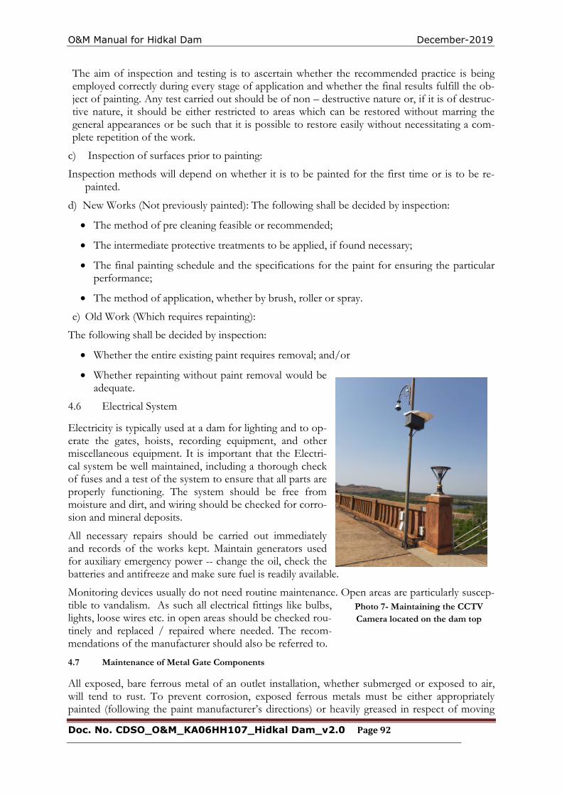
O&M Manual for Hidkal Dam December-2019
Doc. No. CDSO_O&M_KA06HH107_Hidkal Dam_v2.0 Page 92
The aim of inspection and testing is to ascertain whether the recommended practice is being employed correctly during every stage of application and whether the final results fulfill the ob-ject of painting. Any test carried out should be of non – destructive nature or, if it is of destruc-tive nature, it should be either restricted to areas which can be restored without marring the general appearances or be such that it is possible to restore easily without necessitating a com-plete repetition of the work.
c) Inspection of surfaces prior to painting:
Inspection methods will depend on whether it is to be painted for the first time or is to be re-painted.
d) New Works (Not previously painted): The following shall be decided by inspection:
The method of pre cleaning feasible or recommended;
The intermediate protective treatments to be applied, if found necessary;
The final painting schedule and the specifications for the paint for ensuring the particular performance;
The method of application, whether by brush, roller or spray.
e) Old Work (Which requires repainting):
The following shall be decided by inspection:
Whether the entire existing paint requires removal; and/or
Whether repainting without paint removal would be adequate.
4.6 Electrical System
Electricity is typically used at a dam for lighting and to op-erate the gates, hoists, recording equipment, and other miscellaneous equipment. It is important that the Electri-cal system be well maintained, including a thorough check of fuses and a test of the system to ensure that all parts are properly functioning. The system should be free from moisture and dirt, and wiring should be checked for corro-sion and mineral deposits.
All necessary repairs should be carried out immediately and records of the works kept. Maintain generators used for auxiliary emergency power -- change the oil, check the batteries and antifreeze and make sure fuel is readily available.
Monitoring devices usually do not need routine maintenance. Open areas are particularly suscep-tible to vandalism. As such all electrical fittings like bulbs, lights, loose wires etc. in open areas should be checked rou-tinely and replaced / repaired where needed. The recom-mendations of the manufacturer should also be referred to.
4.7 Maintenance of Metal Gate Components
All exposed, bare ferrous metal of an outlet installation, whether submerged or exposed to air, will tend to rust. To prevent corrosion, exposed ferrous metals must be either appropriately painted (following the paint manufacturer’s directions) or heavily greased in respect of moving
Photo 7- Maintaining the CCTV Camera located on the dam top
O&M Manual for Hidkal Dam December-2019
Doc. No. CDSO_O&M_KA06HH107_Hidkal Dam_v2.0 Page 93
parts & on surfaces like guides & track seats on which there is movement of gates. When areas are repainted, it should be ensured that paint is not applied to gate seats, wedges, or stems (where they pass through the stem guides), or on other friction surfaces where paint could cause binding. Heavy grease should be applied on friction surfaces to avoid binding. As rust is especially damaging to contact surfaces, existing rust is to be removed before periodic application of grease.
4.8 Access Roads
For a dam to be operated and maintained, there must be a safe means of access to it at all times. Access road surfaces must be maintained to allow safe passage of automobiles and any required equipment for servicing the dam in any weather conditions. Routine observations of any cut and fill slopes along the sides of the road should be made. If unstable conditions develop assistance of experienced Engineers/Expert Panels should be obtained and remedial measures initiated.
Drains are required to be provided and maintained along roads to remove surface and subsurface drainage. This will prolong the life of the road and help reduce deterioration from rutting. Road surfacing should be repaired or replaced as necessary to maintain the required traffic loadings. In most cases, specialized contractors will be required to perform this maintenance.
4.9 General Cleaning
As already suggested, for proper operation of spillways, sluiceways, approach channels, inlet and outlet structures, stilling basin / energy dissipation arrangements, discharge conduit, dam slopes, trash racks, debris control devices etc., regular and thorough cleaning and removal of debris is necessary. Cleaning is especially important after large floods, which tend to send more debris into the reservoir.
4.10 Materials and Establishment Requirements during Monsoon Period
Materials required during monsoon period for both immediate maintenance and preventive maintenance must be stocked in adequate quantities for emergency situations that may arise. Needful instructions in this regard is enclosed in the O&M Manual. At Hidkal Dam, a 24/7 hour patrol schedule is carried out during monsoon period. At the same time the additional management requirements during monsoon period are enhanced.
4.11 General List of Maintenance Records
Maintenance records are of utmost importance. Records are kept of all maintenance activities, both immediate and preventive maintenance works. Essential information to be recorded include the following:
Date and time of maintenance, Weather conditions, Type of maintenance, Name of person, title and / or contractor performing maintenance, Description of work performed, Length of time it took to complete the work with dates, Equipment and materials used, and Before and after dated photographs.
The data is recorded by the person responsible for maintenance.
O&M Manual for Hidkal Dam December-2019
Doc. No. CDSO_O&M_KA06HH107_Hidkal Dam_v2.0 Page 94
4.12 Preparation of O&M budget
The O&M budget for Hidkal Dam includes the following items:
i) Establishment Cost of Regular Staff - Salaries and allowances, Bonus, Medical Reim-bursement, LTC, Leave Encashment, pension benefits, etc. (as applicable).
ii) Establishment Cost of Work charged Staff - Salaries and allowances, Bonus, Medical Re-imbursement, LTC, Leave Encashment, Pension benefits, TA and DA , etc. (as applica-ble).
iii) Establishment Cost of Daily wage Staff - Salaries and allowances, TA and DA etc. (as ap-plicable).
iv) Office Expenses – Rent for office, Telephone/Mobile/any other Telecommunication bills, Electricity bills, water bills, Office stationery, Day to day office requirements.
v) Motor Vehicles - Running and Maintenance cost of inspection vehicles, Cost of hiring of vehicles as required
vi) Maintenance of Colony - Maintenance of staff quarters, colony roads, Electricity, Sanitary and Water supply systems etc.
vii) T&P - T&P requirements for offices, colony, works etc. as applicable.
viii) Works -Painting, oiling, greasing, overhauling of HM equipment’s, Repair/replacement of gates seals & wire ropes, POL for pumps & generator sets, Electricity charges and mainte-nance of Electric systems of dam site, specific requirements for all Civil, H.M & Electrical maintenance works, vegetation removal and mowing of turfing on earth dams, mainte-nance/cleaning of drains in dam, maintenance of lift/elevators in dam (as applicable), maintenance of access roads & basic facilities, provision for flood contingency works dur-ing monsoon, unforeseen events/items (about 10% of the cost of works) etc.
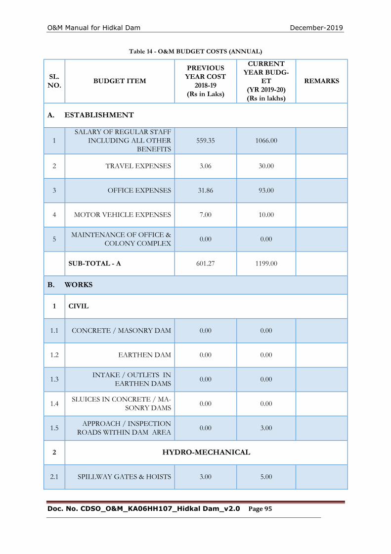
O&M Manual for Hidkal Dam December-2019
Doc. No. CDSO_O&M_KA06HH107_Hidkal Dam_v2.0 Page 95
Table 14 - O&M BUDGET COSTS (ANNUAL)
SL. NO.
BUDGET ITEM
PREVIOUS YEAR COST
2018-19 (Rs in Laks)
CURRENT YEAR BUDG-
ET (YR 2019-20) (Rs in lakhs)
REMARKS
A. ESTABLISHMENT
1 SALARY OF REGULAR STAFF
INCLUDING ALL OTHER BENEFITS
559.35 1066.00
2 TRAVEL EXPENSES 3.06 30.00
3 OFFICE EXPENSES 31.86 93.00
4 MOTOR VEHICLE EXPENSES 7.00 10.00
5 MAINTENANCE OF OFFICE &
COLONY COMPLEX 0.00 0.00
SUB-TOTAL - A 601.27 1199.00
B. WORKS
1 CIVIL
1.1 CONCRETE / MASONRY DAM 0.00 0.00
1.2 EARTHEN DAM 0.00 0.00
1.3 INTAKE / OUTLETS IN
EARTHEN DAMS 0.00 0.00
1.4 SLUICES IN CONCRETE / MA-
SONRY DAMS 0.00 0.00
1.5 APPROACH / INSPECTION
ROADS WITHIN DAM AREA 0.00 3.00
2 HYDRO-MECHANICAL
2.1 SPILLWAY GATES & HOISTS 3.00 5.00
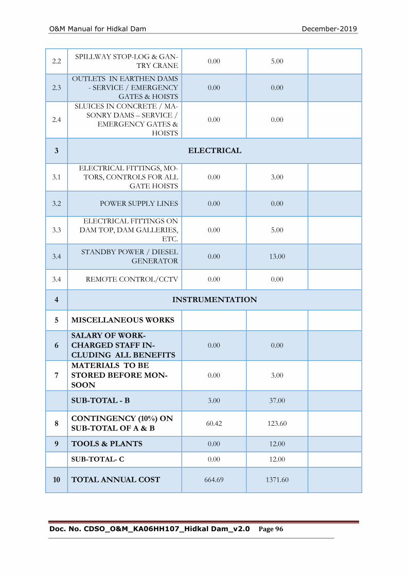
O&M Manual for Hidkal Dam December-2019
Doc. No. CDSO_O&M_KA06HH107_Hidkal Dam_v2.0 Page 96
2.2 SPILLWAY STOP-LOG & GAN-
TRY CRANE 0.00 5.00
2.3 OUTLETS IN EARTHEN DAMS
- SERVICE / EMERGENCY GATES & HOISTS
0.00 0.00
2.4
SLUICES IN CONCRETE / MA-SONRY DAMS – SERVICE /
EMERGENCY GATES & HOISTS
0.00 0.00
3 ELECTRICAL
3.1 ELECTRICAL FITTINGS, MO-
TORS, CONTROLS FOR ALL GATE HOISTS
0.00 3.00
3.2 POWER SUPPLY LINES 0.00 0.00
3.3 ELECTRICAL FITTINGS ON
DAM TOP, DAM GALLERIES, ETC.
0.00 5.00
3.4 STANDBY POWER / DIESEL
GENERATOR 0.00 13.00
3.4 REMOTE CONTROL/CCTV 0.00 0.00
4 INSTRUMENTATION
5 MISCELLANEOUS WORKS
6 SALARY OF WORK- CHARGED STAFF IN-CLUDING ALL BENEFITS
0.00 0.00
7 MATERIALS TO BE STORED BEFORE MON-SOON
0.00 3.00
SUB-TOTAL - B 3.00 37.00
8 CONTINGENCY (10%) ON SUB-TOTAL OF A & B
60.42 123.60
9 TOOLS & PLANTS 0.00 12.00
SUB-TOTAL- C 0.00 12.00
10 TOTAL ANNUAL COST 664.69 1371.60

O&M Manual for Hidkal Dam December-2019
Doc. No. CDSO_O&M_KA06HH107_Hidkal Dam_v2.0 Page 97
O&M Manual for Hidkal Dam December-2019
Doc. No. CDSO_O&M_KA06HH107_Hidkal Dam_v2.0 Page 98
4.13 Maintenance Records
Maintenance records are of utmost importance. A record shall be kept for all maintenance activi-ties, both immediate and preventive maintenance works. Information that must be recorded in-cludes, but not limited to, the following:
date and time of maintenance,
weather conditions,
the type of maintenance,
name of person or contractor performing maintenance,
description of work performed,
the length of time it took to complete the work with dates,
equipment and materials used, and
before and after photographs.
The data should be recorded by the person responsible for maintenance.
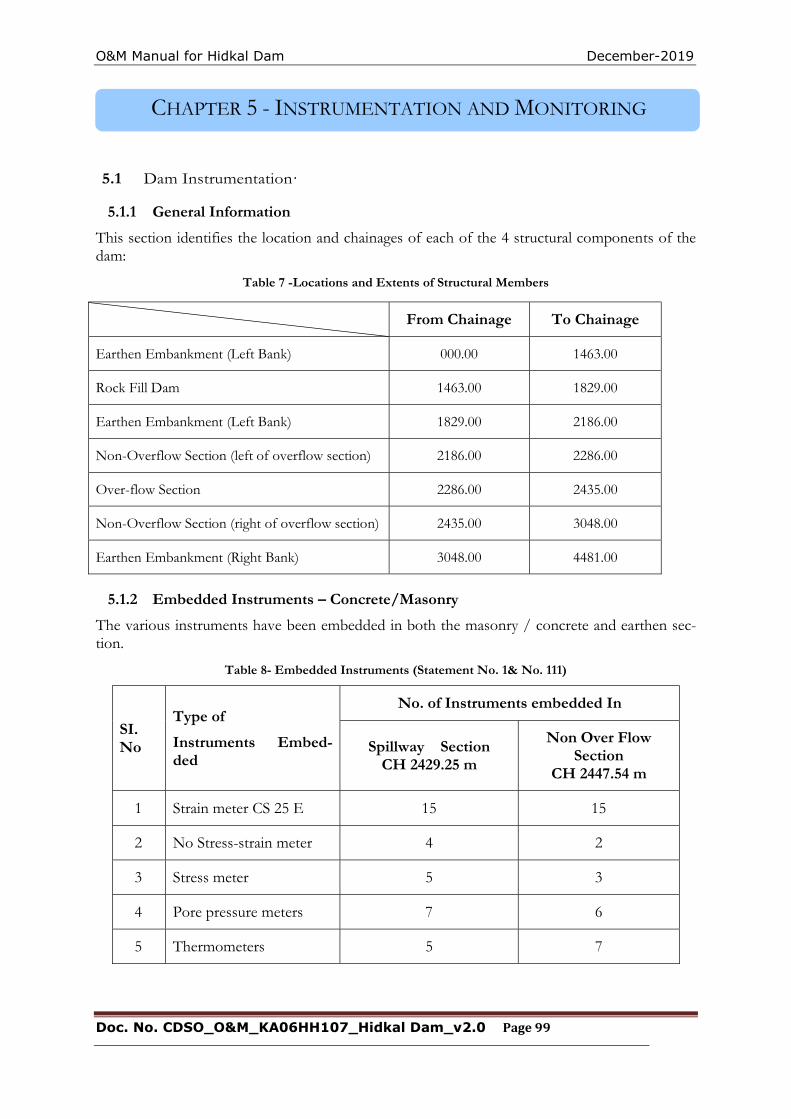
O&M Manual for Hidkal Dam December-2019
Doc. No. CDSO_O&M_KA06HH107_Hidkal Dam_v2.0 Page 99
CHAPTER 5 - INSTRUMENTATION AND MONITORING
5.1 Dam Instrumentation·
5.1.1 General Information
This section identifies the location and chainages of each of the 4 structural components of the dam:
Table 7 -Locations and Extents of Structural Members
5.1.2 Embedded Instruments – Concrete/Masonry
The various instruments have been embedded in both the masonry / concrete and earthen sec-tion.
Table 8- Embedded Instruments (Statement No. 1& No. 111)
SI. No
Type of
Instruments Embed-ded
No. of Instruments embedded In
Spillway Section CH 2429.25 m
Non Over Flow Section
CH 2447.54 m
1 Strain meter CS 25 E 15 15
2 No Stress-strain meter 4 2
3 Stress meter 5 3
4 Pore pressure meters 7 6
5 Thermometers 5 7
From Chainage To Chainage
Earthen Embankment (Left Bank) 000.00 1463.00
Rock Fill Dam 1463.00 1829.00
Earthen Embankment (Left Bank) 1829.00 2186.00
Non-Overflow Section (left of overflow section) 2186.00 2286.00
Over-flow Section 2286.00 2435.00
Non-Overflow Section (right of overflow section) 2435.00 3048.00
Earthen Embankment (Right Bank) 3048.00 4481.00
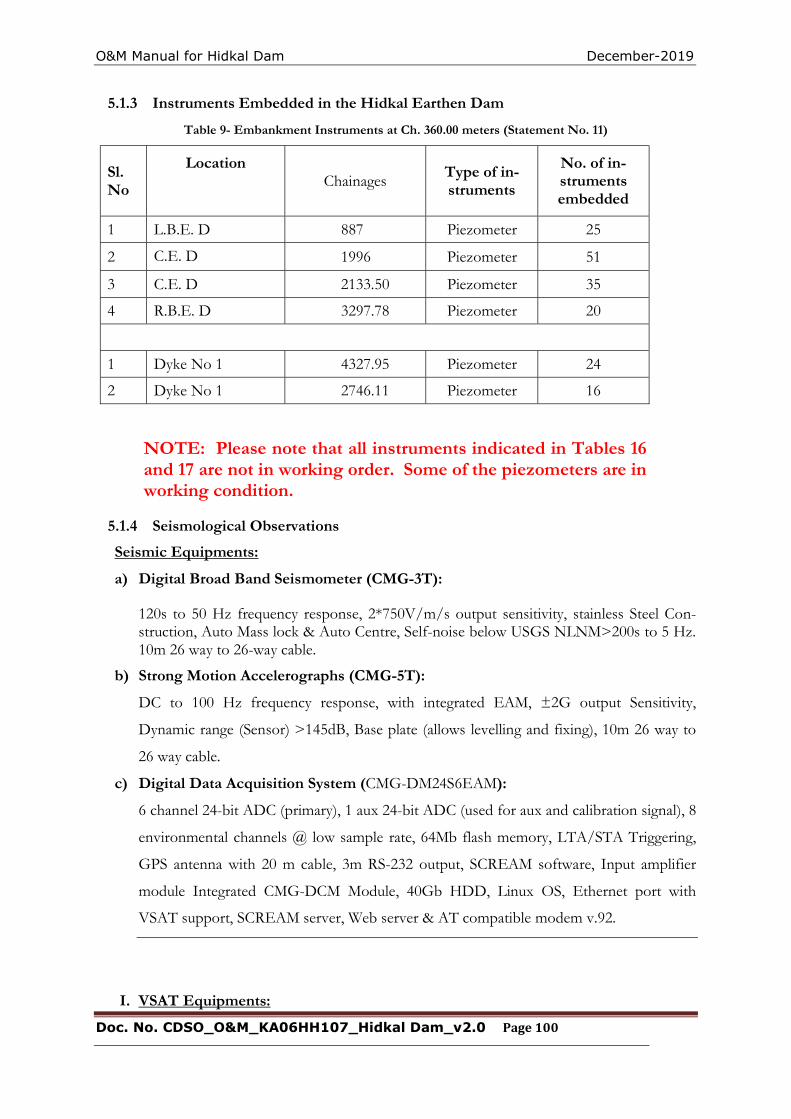
O&M Manual for Hidkal Dam December-2019
Doc. No. CDSO_O&M_KA06HH107_Hidkal Dam_v2.0 Page 100
5.1.3 Instruments Embedded in the Hidkal Earthen Dam
Table 9- Embankment Instruments at Ch. 360.00 meters (Statement No. 11)
Sl. No
Location Chainages
Type of in-struments
No. of in-struments embedded
1 L.B.E. D 887 Piezometer 25
2 C.E. D 1996 Piezometer 51
3 C.E. D 2133.50 Piezometer 35
4 R.B.E. D 3297.78 Piezometer 20
1 Dyke No 1 4327.95 Piezometer 24
2 Dyke No 1 2746.11 Piezometer 16
NOTE: Please note that all instruments indicated in Tables 16 and 17 are not in working order. Some of the piezometers are in working condition.
5.1.4 Seismological Observations
Seismic Equipments:
a) Digital Broad Band Seismometer (CMG-3T):
120s to 50 Hz frequency response, 2*750V/m/s output sensitivity, stainless Steel Con-struction, Auto Mass lock & Auto Centre, Self-noise below USGS NLNM>200s to 5 Hz. 10m 26 way to 26-way cable.
b) Strong Motion Accelerographs (CMG-5T):
DC to 100 Hz frequency response, with integrated EAM, ±2G output Sensitivity,
Dynamic range (Sensor) >145dB, Base plate (allows levelling and fixing), 10m 26 way to
26 way cable.
c) Digital Data Acquisition System (CMG-DM24S6EAM):
6 channel 24-bit ADC (primary), 1 aux 24-bit ADC (used for aux and calibration signal), 8
environmental channels @ low sample rate, 64Mb flash memory, LTA/STA Triggering,
GPS antenna with 20 m cable, 3m RS-232 output, SCREAM software, Input amplifier
module Integrated CMG-DCM Module, 40Gb HDD, Linux OS, Ethernet port with
VSAT support, SCREAM server, Web server & AT compatible modem v.92.
I. VSAT Equipments:
O&M Manual for Hidkal Dam December-2019
Doc. No. CDSO_O&M_KA06HH107_Hidkal Dam_v2.0 Page 101
a) 1.2M Antenna Xc band suitable for site locations in Karnataka (Prodelin make, India).
b) FTDMA VSAT, IDU, ODU and 30m IFL cable, Xc band with 24 V DC input power
(Gilat make, Israel).
II. Solar Power Supply System (12V & 24V):
a) For Seismic Instrumentation: Solar Panels-12V, 60Watts, SMF Batteries-12V, 75 Ah,
Solar Charge Control Units, CCU-12V, 10A, Mounting Structures Roof top/Ground level
of Building for housing the Seismometer and Solar Lighting.
b) For VSAT Telemetry: Solar Panels-24V, 160Watts, SMF Batteries-12V, 200 Ah), Solar
Charge Control Units, CCU-24V, 10A), Mounting Structures
Roof top/Ground level of Building for housing the Seismometer and Solar Lighting.
5.1.5 Parameters being permanently Monitored
Observations of the following parameters need to be continued but not limited to;
• Water levels in the reservoir.
• Hydro-meteorological observations.
• Seepage observations using V-notches/ weirs etc.
• Displacements in the dam by means of survey observations using prism/paper targets fixed at structures, tilt meters or repaired plumb lines, etc.
• Uplift pressures at dam base using stand pipes in Gravity dams.
In case some of the instruments are not in working condition following are some of the steps to be done;
i) In case connecting cables of the non-working instruments are accessible, the manufacturer of the said instruments should be approached for checking and rectification of the installations to make instruments work.
ii) In case the embedded non-working instruments cannot be repaired, the same are to be abandoned.
5.1.6 Frequency of Monitoring
As a rule of thumb, simple visual observations should be made during each visit to the dam and not less than monthly. Immediate readings should be taken following a storm or earthquake. Suggested frequency of measurements is given in the following table. These are generally as per the Guidelines on Instrumentation for dams (CWC).
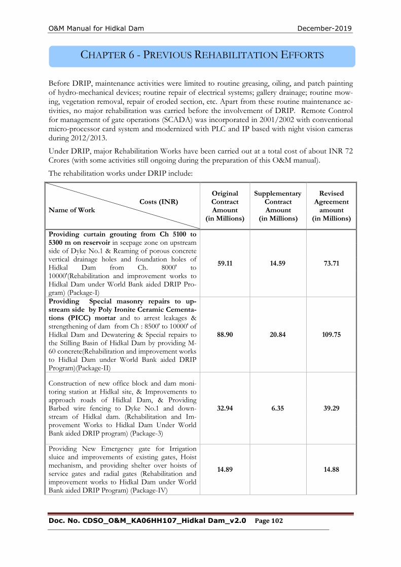
O&M Manual for Hidkal Dam December-2019
Doc. No. CDSO_O&M_KA06HH107_Hidkal Dam_v2.0 Page 102
CHAPTER 6 - PREVIOUS REHABILITATION EFFORTS
Before DRIP, maintenance activities were limited to routine greasing, oiling, and patch painting of hydro-mechanical devices; routine repair of electrical systems; gallery drainage; routine mow-ing, vegetation removal, repair of eroded section, etc. Apart from these routine maintenance ac-tivities, no major rehabilitation was carried before the involvement of DRIP. Remote Control for management of gate operations (SCADA) was incorporated in 2001/2002 with conventional micro-processor card system and modernized with PLC and IP based with night vision cameras during 2012/2013.
Under DRIP, major Rehabilitation Works have been carried out at a total cost of about INR 72 Crores (with some activities still ongoing during the preparation of this O&M manual).
The rehabilitation works under DRIP include:
Costs (INR) Name of Work
Original Contract Amount
(in Millions)
Supplementary Contract Amount
(in Millions)
Revised Agreement
amount (in Millions)
Providing curtain grouting from Ch 5100 to 5300 m on reservoir in seepage zone on upstream side of Dyke No.1 & Reaming of porous concrete vertical drainage holes and foundation holes of Hidkal Dam from Ch. 8000' to 10000'(Rehabilitation and improvement works to Hidkal Dam under World Bank aided DRIP Pro-gram) (Package-I)
59.11 14.59 73.71
Providing Special masonry repairs to up-stream side by Poly Ironite Ceramic Cementa-tions (PICC) mortar and to arrest leakages & strengthening of dam from Ch : 8500' to 10000' of Hidkal Dam and Dewatering & Special repairs to the Stilling Basin of Hidkal Dam by providing M-60 concrete(Rehabilitation and improvement works to Hidkal Dam under World Bank aided DRIP Program)(Package-II)
88.90 20.84 109.75
Construction of new office block and dam moni-toring station at Hidkal site, & Improvements to approach roads of Hidkal Dam, & Providing Barbed wire fencing to Dyke No.1 and down-stream of Hidkal dam. (Rehabilitation and Im-provement Works to Hidkal Dam Under World Bank aided DRIP program) (Package-3)
32.94 6.35 39.29
Providing New Emergency gate for Irrigation sluice and improvements of existing gates, Hoist mechanism, and providing shelter over hoists of service gates and radial gates (Rehabilitation and improvement works to Hidkal Dam under World Bank aided DRIP Program) (Package-IV)
14.89 14.88
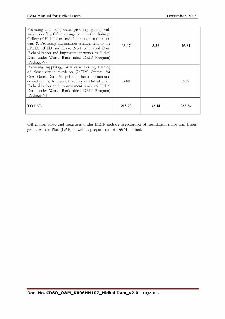
O&M Manual for Hidkal Dam December-2019
Doc. No. CDSO_O&M_KA06HH107_Hidkal Dam_v2.0 Page 103
Providing and fixing water proofing lighting with water proofing Cable arrangement to the drainage Gallery of Hidkal dam and illumination to the main dam & Providing illumination arrangement to the LBED, RBED and Dyke No.1 of Hidkal Dam (Rehabilitation and improvement works to Hidkal Dam under World Bank aided DRIP Program) (Package-V)
13.47 3.36 16.84
Providing, supplying, Installation, Testing, training of closed-circuit television (CCTV) System for Crest Gates, Dam Entry/Exit, other important and crucial points, In view of security of Hidkal Dam. (Rehabilitation and improvement work to Hidkal Dam under World Bank aided DRIP Program) (Package-VI)
3.89 3.89
TOTAL 213.20 45.14 258.34
Other non-structural measures under DRIP include preparation of inundation maps and Emer-gency Action Plan (EAP) as well as preparation of O&M manual.
O&M Manual for Hidkal Dam December-2019
Doc. No. CDSO_O&M_KA06HH107_Hidkal Dam_v2.0 Page 104
CHAPTER 7 - UPDATING THE MANUAL
As features of the dam and appurtenant structures change occasionally, the O&M Manual must be edited and portions rewritten to reflect these changes. This important task is often ignored. Updating information in the O&M Manual should be done whenever major changes like con-struction of an additional spillway, construction of dam on the upstream etc. take place. Aspects to be considered when updating include:
Increase/decrease in the frequency of an inspection or the maintenance routine based on additional data/ experience acquired.
Changes in the operation and/or maintenance procedures based on additional da-ta/experience acquired.
Alterations to the project data because of changes/modifications in the dam by way of addi-tional spillway etc.
All up-dates/revisions of the O&M Manual need to be sent to all the locations/addresses to whom the copies of the original O&M Manual had been sent earlier. It is recommended that O&M Manuals be reviewed/ updated after every 10 years by the respective Dam Owners.
O&M Manual for Hidkal Dam December-2019
Doc. No. CDSO_O&M_KA06HH0107_Hidkal Dam_v2.0 Page 105
APPENDIX 1 – BASIC DRAWINGS OF HIDKAL DAM
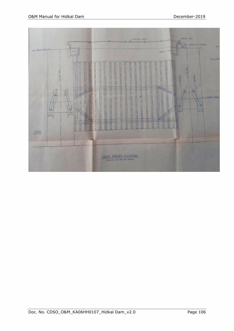
O&M Manual for Hidkal Dam December-2019
Doc. No. CDSO_O&M_KA06HH0107_Hidkal Dam_v2.0 Page 106
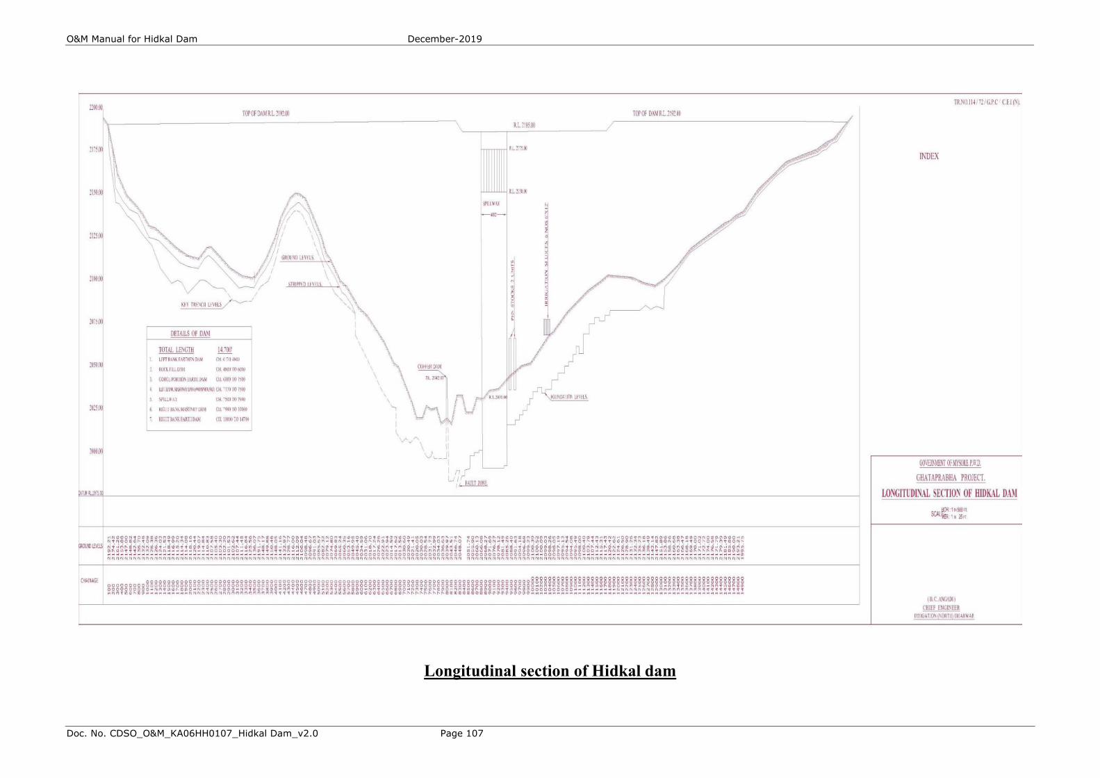
O&M Manual for Hidkal Dam December-2019
Doc. No. CDSO_O&M_KA06HH0107_Hidkal Dam_v2.0 Page 107
Longitudinal section of Hidkal dam
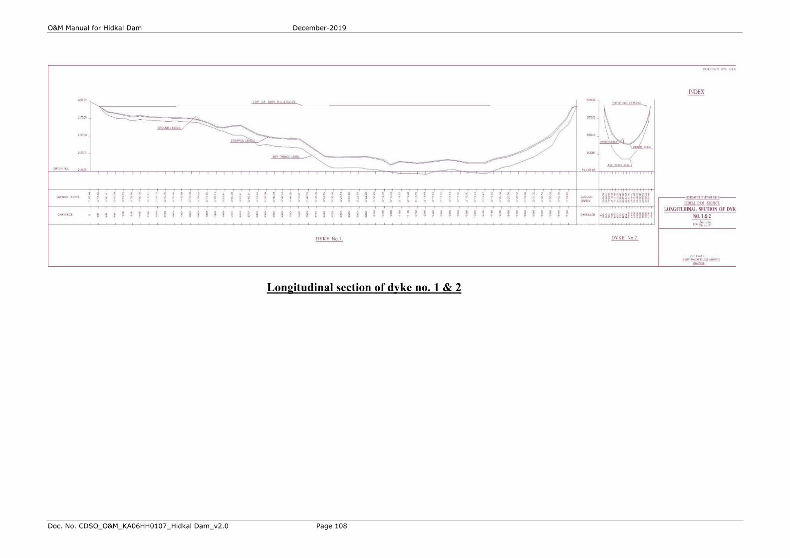
O&M Manual for Hidkal Dam December-2019
Doc. No. CDSO_O&M_KA06HH0107_Hidkal Dam_v2.0 Page 108
Longitudinal section of dyke no. 1 & 2
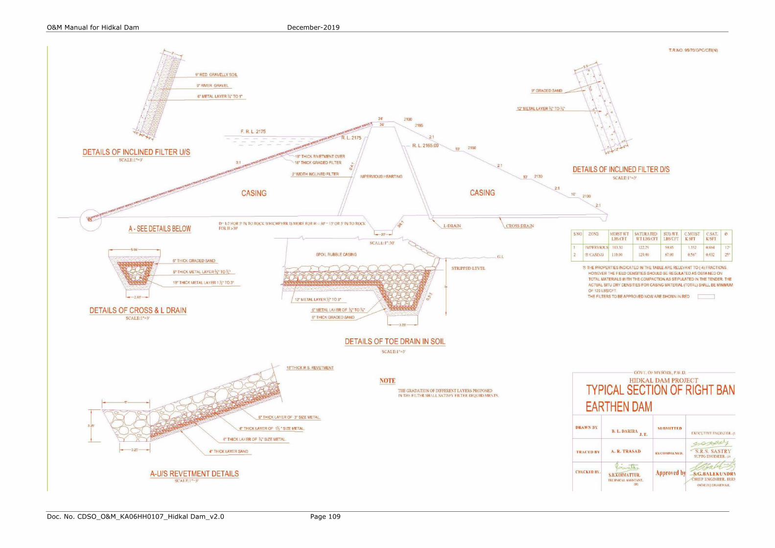
O&M Manual for Hidkal Dam December-2019
Doc. No. CDSO_O&M_KA06HH0107_Hidkal Dam_v2.0 Page 109
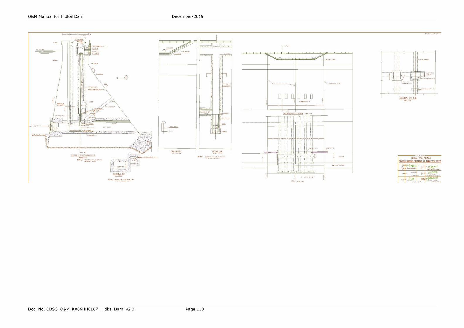
O&M Manual for Hidkal Dam December-2019
Doc. No. CDSO_O&M_KA06HH0107_Hidkal Dam_v2.0 Page 110
O&M Manual for Hidkal Dam December-2019
Doc. No. CDSO_O&M_KA06HH0107_Hidkal Dam_v2.0 Page 111
THIS PAGE LEFT BLANK INTENTIONALLY
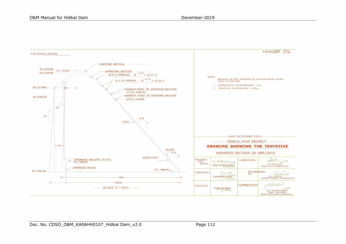
O&M Manual for Hidkal Dam December-2019
Doc. No. CDSO_O&M_KA06HH0107_Hidkal Dam_v2.0 Page 112
O&M Manual for Hidkal Dam December-2019
Doc. No. CDSO_O&M_KA06HH0107_Hidkal Dam_v2.0 Page 113
THIS PAGE LEFT BLANK INTENTIONALLY
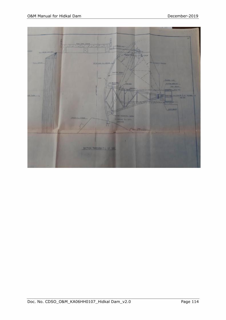
O&M Manual for Hidkal Dam December-2019
Doc. No. CDSO_O&M_KA06HH0107_Hidkal Dam_v2.0 Page 114

O&M Manual for Hidkal Dam December-2019
Doc. No. CDSO_O&M_KA06HH0107_Hidkal Dam_v2.0 Page 115
THIS PAGE LEFT BLANK INTENTIONALLY

O&M Manual for Hidkal Dam December-2019
Doc. No. CDSO_O&M_KA06HH0107_Hidkal Dam_v2.0 Page 116
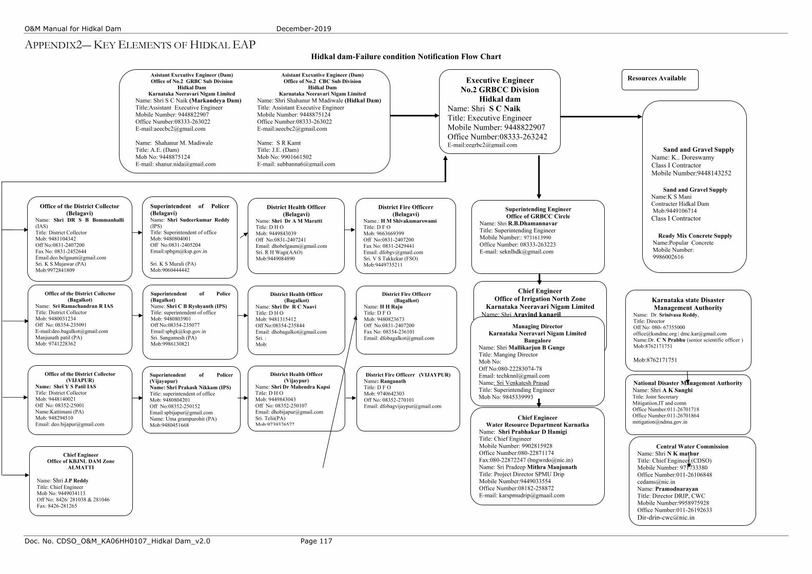
O&M Manual for Hidkal Dam December-2019
Doc. No. CDSO_O&M_KA06HH0107_Hidkal Dam_v2.0 Page 117
APPENDIX2― KEY ELEMENTS OF HIDKAL EAP Hidkal dam-Failure condition Notification Flow Chart
Asistant Exexutive Engineer (Dam) Office of No.2 CBC Sub Division
Hidkal Dam Karnataka Neeravari Nigam Limited
Name: Shri Shahanur M Madiwale (Hidkal Dam) Title: Assistant Executive Engineer Mobile Number: 9448875124 Office Number:08333-263022 E-mail:[email protected] Name: S R Kamt Title: J.E. (Dam) Mob No: 9901661502 E-mail: [email protected]
Executive Engineer No.2 GRBCC Division
Hidkal dam Name: Shri S C Naik Title: Executive Engineer Mobile Number: 9448822907 Office Number:08333-263242 E-mail:[email protected]
Superintending Engineer Office of GRBCC Circle
Name: Shri R.B.Dhamannavar Title: Superintending Engineer Mobile Number:: 9731613990 Office Number: 08333-263223 E-mail: [email protected]
Chief Engineer Office of Irrigation North Zone
Karnataka Neeravari Nigam Limited Name: Shri Aravind kanagil Title: Chief Engineer Mobile Number: 9845326025 Office Number: 0831-2420108 E-mail:[email protected]
Chief Engineer Water Resource Department Karnatka
Name: Shri Prabhakar D Hamigi Title: Chief Engineer Mobile Number: 9902815928 Office Number:080-22871174 Fax:080-22872247 ([email protected]) Name: Sri Pradeep Mithra Manjunath Title: Project Director SPMU Drip Mobile Number:9449033554 Office Number:08182-258872 E-mail: [email protected]
Central Water Commission Name: Shri N K mathur Title: Chief Engineer (CDSO) Mobile Number: 971733380 Office Number:011-26106848 [email protected] Name: Pramodnarayan Title: Director DRIP, CWC Mobile Number:9958975928 Office Number:011-26192633 [email protected]
Office of the District Collector (Belagavi)
Name: Shri DR S B Bommanhalli (IAS) Title: District Collector Mob: 9481104342 Off No:0831-2407200 Fax No: 0831-2452644 [email protected] Sri. K S Mujawar (PA) Mob:9972841809
Office of the District Collector (Bagalkot)
Name: Sri Ramachandran R IAS Title: District Collector Mob: 9480031234 Off No: 08354-235091 E-mail:[email protected] Manjunath patil (PA) Mob: 9741228362
Office of the District Collector (VIJAPUR)
Name: Shri Y S Patil IAS Title: District Collector Mob: 9448140021 Off No: 08352-25001 Name:Kattimani (PA) Mob: 948294510 Email: [email protected]
Sand and Gravel Supply Name: K.. Doreswamy Class I Contractor Mobile Number:9448143252
Ready Mix Concrete Supply Name:Popular Concrete Mobile Number: 9986002616
National Disaster Management Authority Name: Shri A K Sanghi Title: Joint Secretary Mitigatiion,IT and comn Office Number:011-26701718 Office Number:011-26701864 [email protected]
Karnataka state Disaster Management Authority
Name: Dr. Srinivasa Reddy, Title: Director Off No: 080- 67355000 [email protected] | [email protected] Name:Dr. C N Prabhu (senior scientific officer ) Mob:8762171751 Mob:8762171751
Managing Director Karnataka Neeravari Nigam Limited
Bangalore Name: Shri Mallikarjun B Gunge Title: Manging Director Mob No: Off No:080-22283074-78 Email: [email protected] Name: Sri Venkatesh Prasad Title: Superintending Engineer Mob No: 9845339993
Chief Engineer Office of KBJNL DAM Zone
ALMATTI
Name: Shri J.P Reddy Title: Chief Engineer Mob No: 9449034113 Off No: 8426/ 281038 & 281046 Fax: 8426-281265
Resources Available Asistant Exexutive Engineer (Dam) Office of No.2 GRBC Sub Division
Hidkal Dam Karnataka Neeravari Nigam Limited
Name: Shri S C Naik (Markandeya Dam) Title:Assistant Executive Engineer Mobile Number: 9448822907 Office Number:08333-263022 E-mail:[email protected] Name: Shahanur M. Madiwale Title: A.E. (Dam) Mob No: 9448875124 E-mail: [email protected]
Superintendent of Policer (Belagavi) Name: Shri Sudeerkumar Reddy (IPS) Title: Superintendent of office Mob: 9480804001 Off No:0831-2405204 Email:[email protected] Sri. K S Murali (PA) Mob:9060444442
District Health Officer (Belagavi)
Name: Shri Dr A M Maratti Title: D H O Mob: 9449843039 Off No:0831-2407241 Email: [email protected] Sri. R H Wagi(AAO) Mob:9449084890
District Fire Officerr (Belagavi)
Name.: H M Shivakumarswami Title: D F O Mob: 9663669399 Off No:0831-2407200 Fax No: 0831-2429441 Email: [email protected] Sri. V S Takkekar (FSO) Mob:9449735211
District Health Officer (Bagalkot)
Name: Shri Dr R C Naavi Title: D H O Mob: 9481315412 Off No:08354-235844 Email: [email protected] Sri. : Mob:
District Fire Officerr (Bagalkot)
Name: H H Raju Title: D F O Mob: 9480823673 Off No:0831-2407200 Fax No: 08354-236101 Email: [email protected]
Superintendent of Police (Bagalkot) Name: Shri C B Ryshyanth (IPS) Title: superintendent of office Mob: 9480803901 Off No:08354-235077 Email:[email protected] Sri. Sangamesh (PA) Mob:9986130821
Superintendent of Policer (Vijayapur) Name: Shri Prakash Nikkam (IPS) Title: superintendent of office Mob: 9480804201 Off No:08352-250152 Email [email protected] Name: Uma grampurohit (PA) Mob:9480451668
District Health Officer (Vijaypur)
Name: Shri Dr Mahendra Kapsi Title: D H O Mob: 9449843043 Off No: 08352-250107 Email: [email protected] Sri. Telii(PA) Mob:9739376572
District Fire Officerr (VIJAYPUR) Name: Ranganath Title: D F O Mob: 9740642303 Off No: 08352-270101 Email: [email protected]
Sand and Gravel Supply Name:K S Mani Contracter Hidkal Dam Mob:9449106714 Class I Contractor

O&M Manual for Hidkal Dam December-2019
Doc. No. CDSO_O&M_KA06HH0107_Hidkal Dam_v2.0 Page 118
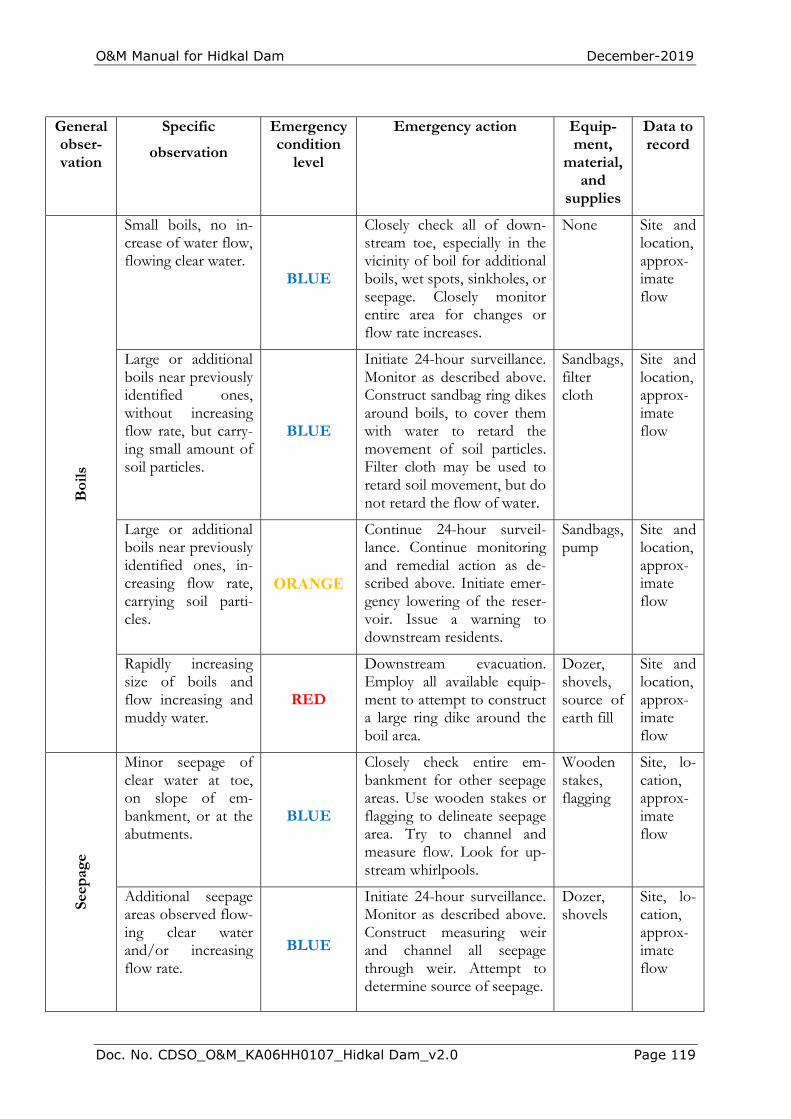
O&M Manual for Hidkal Dam December-2019
Doc. No. CDSO_O&M_KA06HH0107_Hidkal Dam_v2.0 Page 119
General obser-vation
Specific
observation
Emergency condition
level
Emergency action Equip-ment,
material, and
supplies
Data to record
Boi
ls
Small boils, no in-crease of water flow, flowing clear water.
BLUE
Closely check all of down-stream toe, especially in the vicinity of boil for additional boils, wet spots, sinkholes, or seepage. Closely monitor entire area for changes or flow rate increases.
None Site and location, approx-imate flow
Large or additional boils near previously identified ones, without increasing flow rate, but carry-ing small amount of soil particles.
BLUE
Initiate 24-hour surveillance. Monitor as described above. Construct sandbag ring dikes around boils, to cover them with water to retard the movement of soil particles. Filter cloth may be used to retard soil movement, but do not retard the flow of water.
Sandbags, filter cloth
Site and location, approx-imate flow
Large or additional boils near previously identified ones, in-creasing flow rate, carrying soil parti-cles.
ORANGE
Continue 24-hour surveil-lance. Continue monitoring and remedial action as de-scribed above. Initiate emer-gency lowering of the reser-voir. Issue a warning to downstream residents.
Sandbags, pump
Site and location, approx-imate flow
Rapidly increasing size of boils and flow increasing and muddy water.
RED
Downstream evacuation. Employ all available equip-ment to attempt to construct a large ring dike around the boil area.
Dozer, shovels, source of earth fill
Site and location, approx-imate flow
Seep
age
Minor seepage of clear water at toe, on slope of em-bankment, or at the abutments.
BLUE
Closely check entire em-bankment for other seepage areas. Use wooden stakes or flagging to delineate seepage area. Try to channel and measure flow. Look for up-stream whirlpools.
Wooden stakes, flagging
Site, lo-cation, approx-imate flow
Additional seepage areas observed flow-ing clear water and/or increasing flow rate.
BLUE
Initiate 24-hour surveillance. Monitor as described above. Construct measuring weir and channel all seepage through weir. Attempt to determine source of seepage.
Dozer, shovels
Site, lo-cation, approx-imate flow
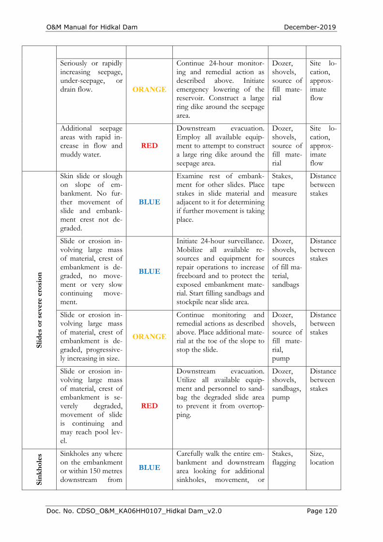
O&M Manual for Hidkal Dam December-2019
Doc. No. CDSO_O&M_KA06HH0107_Hidkal Dam_v2.0 Page 120
Seriously or rapidly increasing seepage, under-seepage, or drain flow. ORANGE
Continue 24-hour monitor-ing and remedial action as described above. Initiate emergency lowering of the reservoir. Construct a large ring dike around the seepage area.
Dozer, shovels, source of fill mate-rial
Site lo-cation, approx-imate flow
Additional seepage areas with rapid in-crease in flow and muddy water.
RED
Downstream evacuation. Employ all available equip-ment to attempt to construct a large ring dike around the seepage area.
Dozer, shovels, source of fill mate-rial
Site lo-cation, approx-imate flow
Slid
es o
r se
vere
ero
sion
Skin slide or slough on slope of em-bankment. No fur-ther movement of slide and embank-ment crest not de-graded.
BLUE
Examine rest of embank-ment for other slides. Place stakes in slide material and adjacent to it for determining if further movement is taking place.
Stakes, tape measure
Distance between stakes
Slide or erosion in-volving large mass of material, crest of embankment is de-graded, no move-ment or very slow continuing move-ment.
BLUE
Initiate 24-hour surveillance. Mobilize all available re-sources and equipment for repair operations to increase freeboard and to protect the exposed embankment mate-rial. Start filling sandbags and stockpile near slide area.
Dozer, shovels, sources of fill ma-terial, sandbags
Distance between stakes
Slide or erosion in-volving large mass of material, crest of embankment is de-graded, progressive-ly increasing in size.
ORANGE
Continue monitoring and remedial actions as described above. Place additional mate-rial at the toe of the slope to stop the slide.
Dozer, shovels, source of fill mate-rial, pump
Distance between stakes
Slide or erosion in-volving large mass of material, crest of embankment is se-verely degraded, movement of slide is continuing and may reach pool lev-el.
RED
Downstream evacuation. Utilize all available equip-ment and personnel to sand-bag the degraded slide area to prevent it from overtop-ping.
Dozer, shovels, sandbags, pump
Distance between stakes
Sink
hole
s Sinkholes any where on the embankment or within 150 metres downstream from
BLUE
Carefully walk the entire em-bankment and downstream area looking for additional sinkholes, movement, or
Stakes, flagging
Size, location
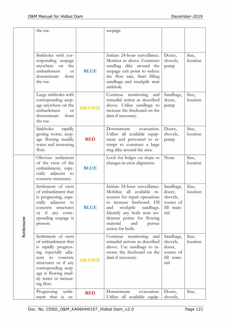
O&M Manual for Hidkal Dam December-2019
Doc. No. CDSO_O&M_KA06HH0107_Hidkal Dam_v2.0 Page 121
the toe. seepage.
Sinkholes with cor-responding seepage anywhere on the embankment or downstream from the toe.
BLUE
Initiate 24-hour surveillance. Monitor as above. Construct sandbag dike around the seepage exit point to reduce the flow rate. Start filling sandbags and stockpile near sinkhole.
Dozer, shovels, pump
Size, location
Large sinkholes with corresponding seep-age anywhere on the embankment or downstream from the toe.
ORANGE
Continue monitoring and remedial action as described above. Utilize sandbags to increase the freeboard on the dam if necessary.
Sandbags, dozer, pump
Size, location
Sinkholes rapidly getting worse, seep-age flowing muddy water and increasing flow.
RED
Downstream evacuation. Utilize all available equip-ment and personnel to at-tempt to construct a large ring dike around the area.
Dozer, shovels, pump
Size, location
Sett
lem
ent
Obvious settlement of the crest of the embankment, espe-cially adjacent to concrete structures.
BLUE
Look for bulges on slope or changes in crest alignment.
None Size, location
Settlement of crest of embankment that is progressing, espe-cially adjacent to concrete structures or if any corre-sponding seepage is present.
BLUE
Initiate 24-hour surveillance. Mobilize all available re-sources for repair operations to increase freeboard. Fill and stockpile sandbags. Identify any boils near set-tlement points for flowing material and pursue action for boils.
Sandbags, dozer, shovels, source of fill mate-rial
Size, location
Settlement of crest of embankment that is rapidly progress-ing especially adja-cent to concrete structures or if any corresponding seep-age is flowing mud-dy water or increas-ing flow.
ORANGE
Continue monitoring and remedial actions as described above. Use sandbags to in-crease the freeboard on the dam if necessary.
Sandbags, shovels, dozer, source of fill mate-rial
Size, location
Progressing settle-ment that is ex-
RED Downstream evacuation. Utilize all available equip-
Dozer, shovels,
Size,
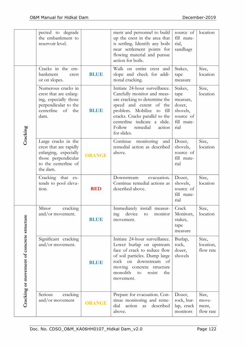
O&M Manual for Hidkal Dam December-2019
Doc. No. CDSO_O&M_KA06HH0107_Hidkal Dam_v2.0 Page 122
pected to degrade the embankment to reservoir level.
ment and personnel to build up the crest in the area that is settling. Identify any boils near settlement points for flowing material and pursue action for boils.
source of fill mate-rial, sandbags
location
Cra
ckin
g
Cracks in the em-bankment crest or on slopes.
BLUE Walk on entire crest and slope and check for addi-tional cracking.
Stakes, tape measure
Size, location
Numerous cracks in crest that are enlarg-ing, especially those perpendicular to the centerline of the dam.
BLUE
Initiate 24-hour surveillance. Carefully monitor and meas-ure cracking to determine the speed and extent of the problem. Mobilize to fill cracks. Cracks parallel to the centerline indicate a slide. Follow remedial action for slides.
Stakes, tape measure, dozer, shovels, source of fill mate-rial
Size, location
Large cracks in the crest that are rapidly enlarging, especially those perpendicular to the centerline of the dam.
ORANGE
Continue monitoring and remedial action as described above.
Dozer, shovels, source of fill mate-rial
Size, location
Cracking that ex-tends to pool eleva-tion. RED
Downstream evacuation. Continue remedial actions as described above.
Dozer, shovels, source of fill mate-rial
Size, location
Cra
ckin
g or
mov
emen
t of
con
cret
e st
ruct
ure
Minor cracking and/or movement.
BLUE
Immediately install measur-ing device to monitor movement.
Crack Monitors, stakes, tape measure
Size, location
Significant cracking and/or movement.
BLUE
Initiate 24-hour surveillance. Lower burlap on upstream face of crack to reduce flow of soil particles. Dump large rock on downstream of moving concrete structure monolith to resist the movement.
Burlap, rock, dozer, shovels
Size, location, flow rate
Serious cracking and/or movement
ORANGE
Prepare for evacuation. Con-tinue monitoring and reme-dial action as described above.
Dozer, rock, bur-lap, crack monitors
Size, move-ment, flow rate
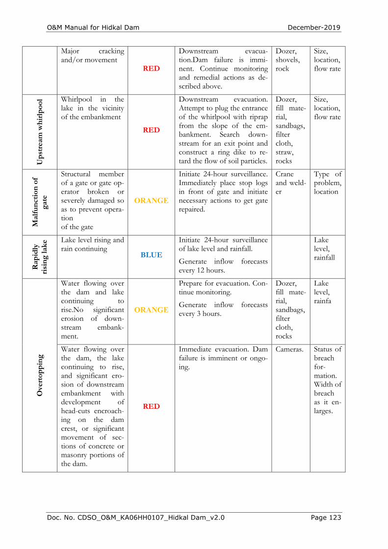
O&M Manual for Hidkal Dam December-2019
Doc. No. CDSO_O&M_KA06HH0107_Hidkal Dam_v2.0 Page 123
Major cracking and/or movement
RED
Downstream evacua-tion.Dam failure is immi-nent. Continue monitoring and remedial actions as de-scribed above.
Dozer, shovels, rock
Size, location, flow rate
Ups
trea
m w
hirl
pool
Whirlpool in the lake in the vicinity of the embankment
RED
Downstream evacuation. Attempt to plug the entrance of the whirlpool with riprap from the slope of the em-bankment. Search down-stream for an exit point and construct a ring dike to re-tard the flow of soil particles.
Dozer, fill mate-rial, sandbags, filter cloth, straw, rocks
Size, location, flow rate
Mal
func
tion
of
gate
Structural member of a gate or gate op-erator broken or severely damaged so as to prevent opera-tion of the gate
ORANGE
Initiate 24-hour surveillance. Immediately place stop logs in front of gate and initiate necessary actions to get gate repaired.
Crane and weld-er
Type of problem, location
Rap
idly
ri
sing
lake
Lake level rising and rain continuing
BLUE
Initiate 24-hour surveillance of lake level and rainfall.
Generate inflow forecasts every 12 hours.
Lake level, rainfall
Ove
rtop
ping
Water flowing over the dam and lake continuing to rise.No significant erosion of down-stream embank-ment.
ORANGE
Prepare for evacuation. Con-tinue monitoring.
Generate inflow forecasts every 3 hours.
Dozer, fill mate-rial, sandbags, filter cloth, rocks
Lake level, rainfa
Water flowing over the dam, the lake continuing to rise, and significant ero-sion of downstream embankment with development of head-cuts encroach-ing on the dam crest, or significant movement of sec-tions of concrete or masonry portions of the dam.
RED
Immediate evacuation. Dam failure is imminent or ongo-ing.
Cameras. Status of breach for-mation. Width of breach as it en-larges.

O&M Manual for Hidkal Dam December-2019
Doc. No. CDSO_O&M_KA06HH0107_Hidkal Dam_v2.0 Page 124
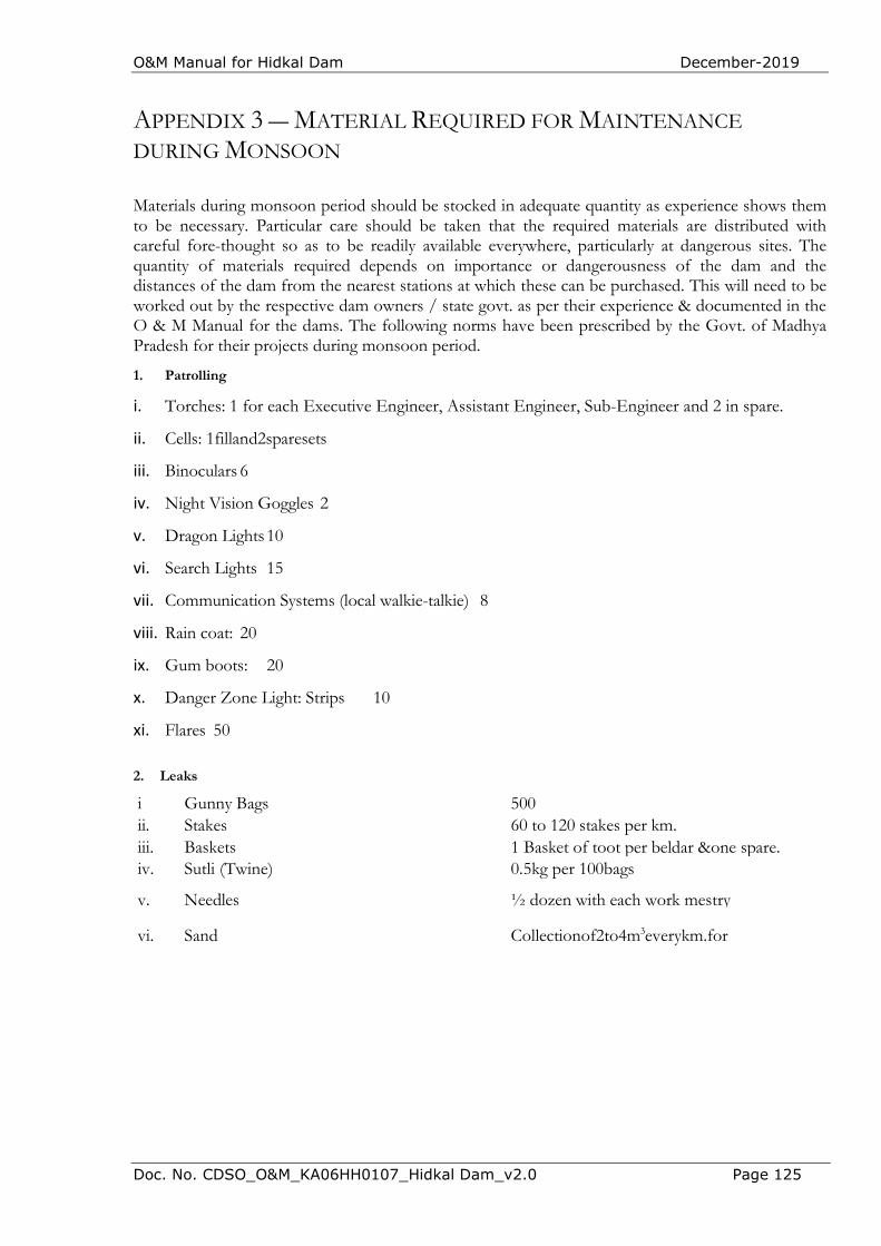
O&M Manual for Hidkal Dam December-2019
Doc. No. CDSO_O&M_KA06HH0107_Hidkal Dam_v2.0 Page 125
APPENDIX 3 ― MATERIAL REQUIRED FOR MAINTENANCE DURING MONSOON
Materials during monsoon period should be stocked in adequate quantity as experience shows them to be necessary. Particular care should be taken that the required materials are distributed with careful fore-thought so as to be readily available everywhere, particularly at dangerous sites. The quantity of materials required depends on importance or dangerousness of the dam and the distances of the dam from the nearest stations at which these can be purchased. This will need to be worked out by the respective dam owners / state govt. as per their experience & documented in the O & M Manual for the dams. The following norms have been prescribed by the Govt. of Madhya Pradesh for their projects during monsoon period.
1. Patrolling
i. Torches: 1 for each Executive Engineer, Assistant Engineer, Sub-Engineer and 2 in spare.
ii. Cells: 1filland2sparesets
iii. Binoculars 6
iv. Night Vision Goggles 2
v. Dragon Lights 10
vi. Search Lights 15
vii. Communication Systems (local walkie-talkie) 8
viii. Rain coat: 20
ix. Gum boots: 20
x. Danger Zone Light: Strips 10
xi. Flares 50
2. Leaks
i Gunny Bags 500 ii. Stakes 60 to 120 stakes per km. iii. Baskets 1 Basket of toot per beldar &one spare. iv. Sutli (Twine) 0.5kg per 100bags
v. Needles ½ dozen with each work mestry
vi. Sand Collectionof2to4m3everykm.for

O&M Manual for Hidkal Dam December-2019
Doc. No. CDSO_O&M_KA06HH0107_Hidkal Dam_v2.0 Page 135
THIS PAGE LEFT INTERNTIOANLLY BLANK
O&M Manual for Hidkal Dam December-2019
Doc. No. CDSO_O&M_KA06HH0107_Hidkal Dam_v2.0 Page 2
Appendix 4 ― Scheduled or Unscheduled Dam Safety Inspection Form
A form designed for use during scheduled dam safety inspections – which includes pre- and post-monsoon inspections – follows. The form contains a comprehensive checklist (Part 2a) of items that are found at dams that need to be evaluated during a safety inspection. The checklist consists of (1) a series of questions that need to be answered as Yes/No/Not Applicable for each inspection item, (2) a remarks box in which critical aspects can be commented upon following each question, and (3) a final condition assessment (Unsatisfactory/Poor/Fair/Satisfactory) for that inspection item. Not all inspection items will be found at a dam. The form concludes with a Consolidated Dam Health Status Report (Part 2b)
.
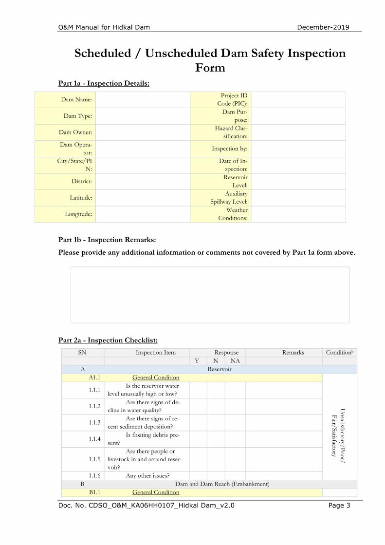
O&M Manual for Hidkal Dam December-2019
Doc. No. CDSO_O&M_KA06HH0107_Hidkal Dam_v2.0 Page 3
Scheduled / Unscheduled Dam Safety Inspection Form
Part 1a - Inspection Details:
Dam Name: Project ID
Code (PIC):
Dam Type: Dam Pur-
pose:
Dam Owner: Hazard Clas-
sification:
Dam Opera-tor:
Inspection by:
City/State/PIN:
Date of In-
spection:
District: Reservoir
Level:
Latitude: Auxiliary
Spillway Level:
Longitude: Weather
Conditions:
Part 1b - Inspection Remarks:
Please provide any additional information or comments not covered by Part 1a form above.
Part 2a - Inspection Checklist:
SN Inspection Item Response Remarks Conditionb
Y N NA A Reservoir
A1.1 General Condition
Unsatisfactory/Poor/ F
air/Satisfactory
1.1.1 Is the reservoir water
level unusually high or low?
1.1.2 Are there signs of de-
cline in water quality?
1.1.3 Are there signs of re-
cent sediment deposition?
1.1.4 Is floating debris pre-
sent?
1.1.5 Are there people or
livestock in and around reser-voir?
1.1.6 Any other issues? B Dam and Dam Reach (Embankment)
B1.1 General Condition
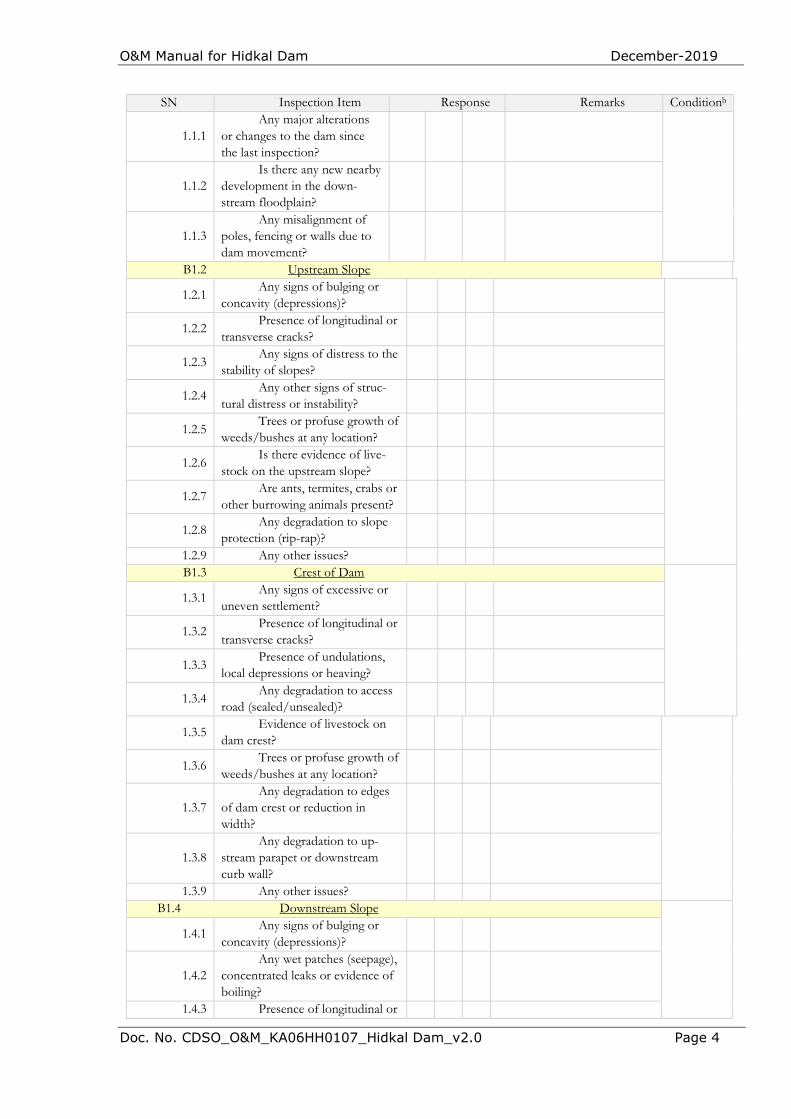
O&M Manual for Hidkal Dam December-2019
Doc. No. CDSO_O&M_KA06HH0107_Hidkal Dam_v2.0 Page 4
SN Inspection Item Response Remarks Conditionb
1.1.1 Any major alterations
or changes to the dam since the last inspection?
1.1.2 Is there any new nearby
development in the down-stream floodplain?
1.1.3 Any misalignment of
poles, fencing or walls due to dam movement?
B1.2 Upstream Slope
1.2.1 Any signs of bulging or
concavity (depressions)?
1.2.2 Presence of longitudinal or
transverse cracks?
1.2.3 Any signs of distress to the
stability of slopes?
1.2.4 Any other signs of struc-
tural distress or instability?
1.2.5 Trees or profuse growth of
weeds/bushes at any location?
1.2.6 Is there evidence of live-
stock on the upstream slope?
1.2.7 Are ants, termites, crabs or
other burrowing animals present?
1.2.8 Any degradation to slope
protection (rip-rap)?
1.2.9 Any other issues? B1.3 Crest of Dam
1.3.1 Any signs of excessive or
uneven settlement?
1.3.2 Presence of longitudinal or
transverse cracks?
1.3.3 Presence of undulations,
local depressions or heaving?
1.3.4 Any degradation to access
road (sealed/unsealed)?
1.3.5 Evidence of livestock on
dam crest?
1.3.6 Trees or profuse growth of
weeds/bushes at any location?
1.3.7 Any degradation to edges
of dam crest or reduction in width?
1.3.8 Any degradation to up-
stream parapet or downstream curb wall?
1.3.9 Any other issues? B1.4 Downstream Slope
1.4.1 Any signs of bulging or
concavity (depressions)?
1.4.2 Any wet patches (seepage),
concentrated leaks or evidence of boiling?
1.4.3 Presence of longitudinal or
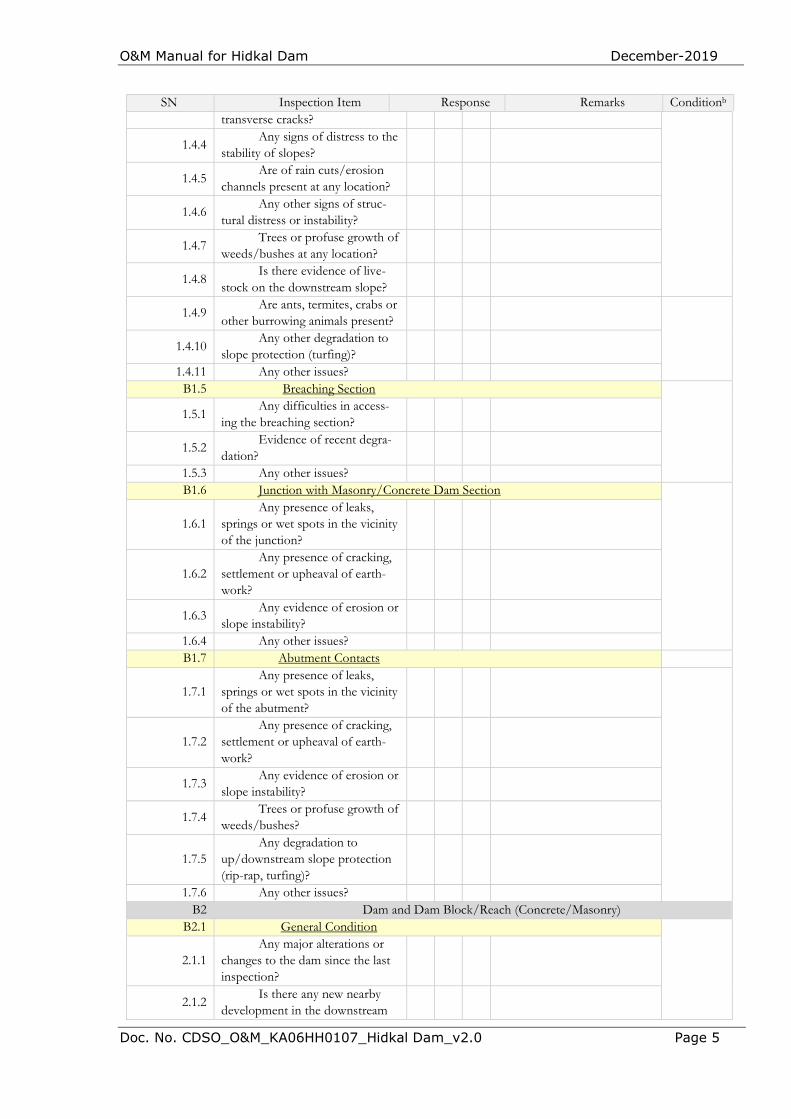
O&M Manual for Hidkal Dam December-2019
Doc. No. CDSO_O&M_KA06HH0107_Hidkal Dam_v2.0 Page 5
SN Inspection Item Response Remarks Conditionb
transverse cracks?
1.4.4 Any signs of distress to the
stability of slopes?
1.4.5 Are of rain cuts/erosion
channels present at any location?
1.4.6 Any other signs of struc-
tural distress or instability?
1.4.7 Trees or profuse growth of
weeds/bushes at any location?
1.4.8 Is there evidence of live-
stock on the downstream slope?
1.4.9 Are ants, termites, crabs or
other burrowing animals present?
1.4.10 Any other degradation to
slope protection (turfing)?
1.4.11 Any other issues? B1.5 Breaching Section
1.5.1 Any difficulties in access-
ing the breaching section?
1.5.2 Evidence of recent degra-
dation?
1.5.3 Any other issues? B1.6 Junction with Masonry/Concrete Dam Section
1.6.1 Any presence of leaks,
springs or wet spots in the vicinity of the junction?
1.6.2 Any presence of cracking,
settlement or upheaval of earth-work?
1.6.3 Any evidence of erosion or
slope instability?
1.6.4 Any other issues? B1.7 Abutment Contacts
1.7.1 Any presence of leaks,
springs or wet spots in the vicinity of the abutment?
1.7.2 Any presence of cracking,
settlement or upheaval of earth-work?
1.7.3 Any evidence of erosion or
slope instability?
1.7.4 Trees or profuse growth of
weeds/bushes?
1.7.5 Any degradation to
up/downstream slope protection (rip-rap, turfing)?
1.7.6 Any other issues? B2 Dam and Dam Block/Reach (Concrete/Masonry)
B2.1 General Condition
2.1.1 Any major alterations or
changes to the dam since the last inspection?
2.1.2 Is there any new nearby
development in the downstream
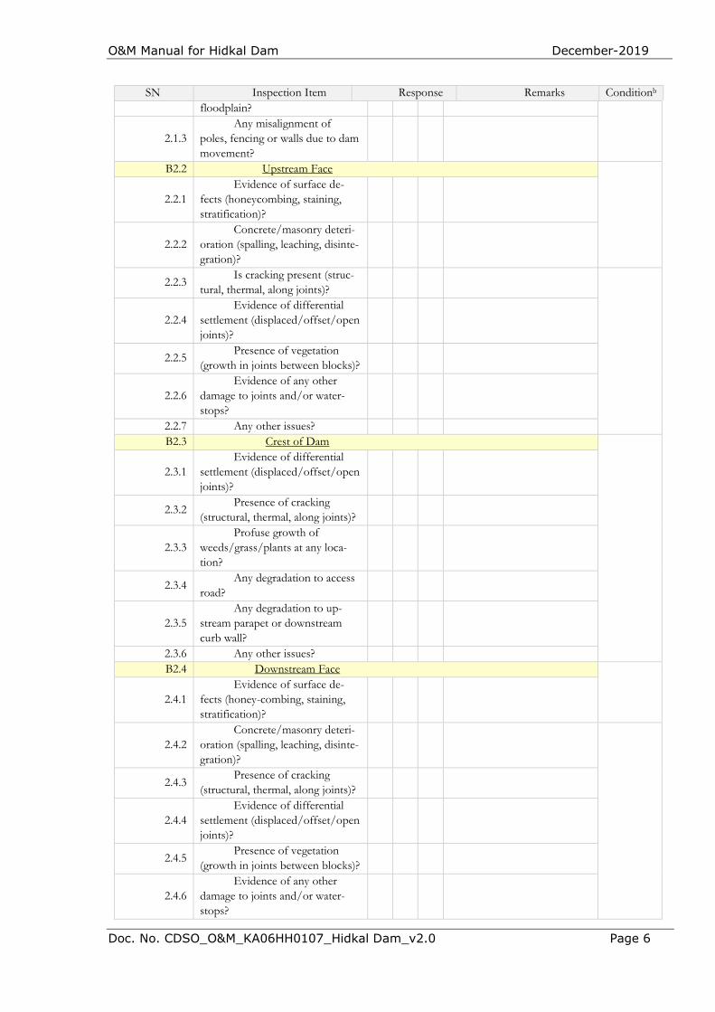
O&M Manual for Hidkal Dam December-2019
Doc. No. CDSO_O&M_KA06HH0107_Hidkal Dam_v2.0 Page 6
SN Inspection Item Response Remarks Conditionb
floodplain?
2.1.3 Any misalignment of
poles, fencing or walls due to dam movement?
B2.2 Upstream Face
2.2.1 Evidence of surface de-
fects (honeycombing, staining, stratification)?
2.2.2 Concrete/masonry deteri-
oration (spalling, leaching, disinte-gration)?
2.2.3 Is cracking present (struc-
tural, thermal, along joints)?
2.2.4 Evidence of differential
settlement (displaced/offset/open joints)?
2.2.5 Presence of vegetation
(growth in joints between blocks)?
2.2.6 Evidence of any other
damage to joints and/or water-stops?
2.2.7 Any other issues? B2.3 Crest of Dam
2.3.1 Evidence of differential
settlement (displaced/offset/open joints)?
2.3.2 Presence of cracking
(structural, thermal, along joints)?
2.3.3 Profuse growth of
weeds/grass/plants at any loca-tion?
2.3.4 Any degradation to access
road?
2.3.5 Any degradation to up-
stream parapet or downstream curb wall?
2.3.6 Any other issues? B2.4 Downstream Face
2.4.1
Evidence of surface de-fects (honey-combing, staining, stratification)?
2.4.2 Concrete/masonry deteri-
oration (spalling, leaching, disinte-gration)?
2.4.3 Presence of cracking
(structural, thermal, along joints)?
2.4.4 Evidence of differential
settlement (displaced/offset/open joints)?
2.4.5 Presence of vegetation
(growth in joints between blocks)?
2.4.6 Evidence of any other
damage to joints and/or water-stops?
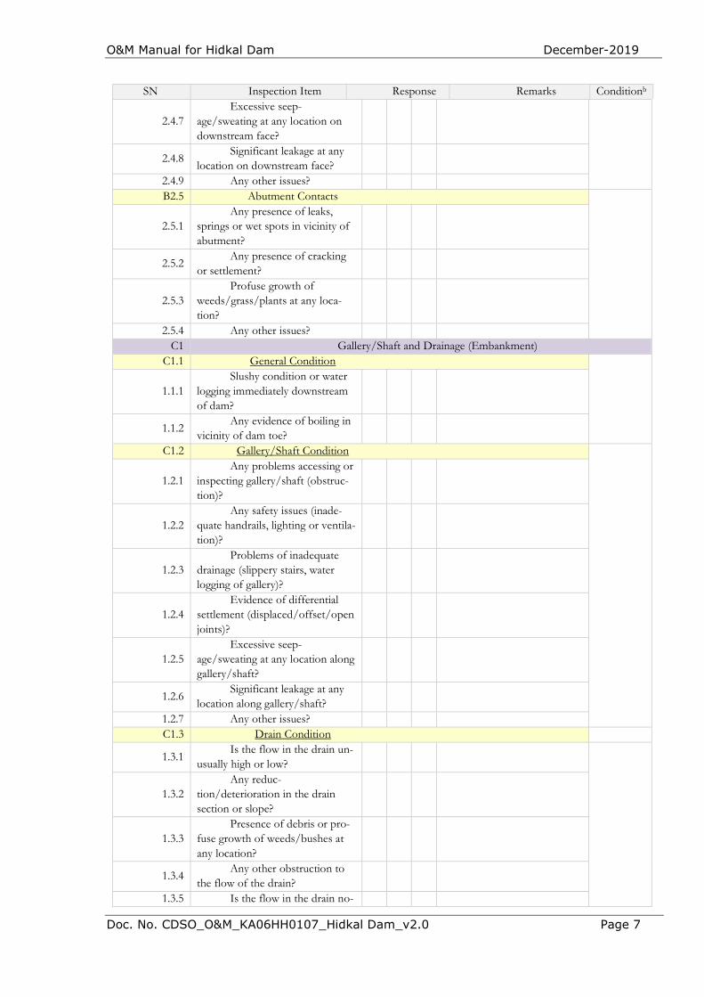
O&M Manual for Hidkal Dam December-2019
Doc. No. CDSO_O&M_KA06HH0107_Hidkal Dam_v2.0 Page 7
SN Inspection Item Response Remarks Conditionb
2.4.7 Excessive seep-
age/sweating at any location on downstream face?
2.4.8 Significant leakage at any
location on downstream face?
2.4.9 Any other issues? B2.5 Abutment Contacts
2.5.1 Any presence of leaks,
springs or wet spots in vicinity of abutment?
2.5.2 Any presence of cracking
or settlement?
2.5.3 Profuse growth of
weeds/grass/plants at any loca-tion?
2.5.4 Any other issues? C1 Gallery/Shaft and Drainage (Embankment)
C1.1 General Condition
1.1.1 Slushy condition or water
logging immediately downstream of dam?
1.1.2 Any evidence of boiling in
vicinity of dam toe?
C1.2 Gallery/Shaft Condition
1.2.1 Any problems accessing or
inspecting gallery/shaft (obstruc-tion)?
1.2.2 Any safety issues (inade-
quate handrails, lighting or ventila-tion)?
1.2.3 Problems of inadequate
drainage (slippery stairs, water logging of gallery)?
1.2.4 Evidence of differential
settlement (displaced/offset/open joints)?
1.2.5 Excessive seep-
age/sweating at any location along gallery/shaft?
1.2.6 Significant leakage at any
location along gallery/shaft?
1.2.7 Any other issues? C1.3 Drain Condition
1.3.1 Is the flow in the drain un-
usually high or low?
1.3.2 Any reduc-
tion/deterioration in the drain section or slope?
1.3.3 Presence of debris or pro-
fuse growth of weeds/bushes at any location?
1.3.4 Any other obstruction to
the flow of the drain?
1.3.5 Is the flow in the drain no-
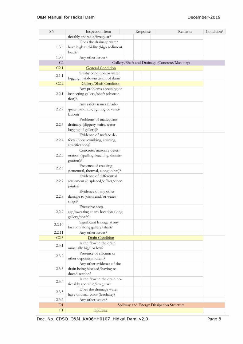
O&M Manual for Hidkal Dam December-2019
Doc. No. CDSO_O&M_KA06HH0107_Hidkal Dam_v2.0 Page 8
SN Inspection Item Response Remarks Conditionb
ticeably sporadic/irregular?
1.3.6 Does the drainage water
have high turbidity (high sediment load)?
1.3.7 Any other issues? C2 Gallery/Shaft and Drainage (Concrete/Masonry)
C2.1 General Condition
2.1.1 Slushy condition or water
logging just downstream of dam?
C2.2 Gallery/Shaft Condition
2.2.1 Any problems accessing or
inspecting gallery/shaft (obstruc-tion)?
2.2.2 Any safety issues (inade-
quate handrails, lighting or venti-lation)?
2.2.3 Problems of inadequate
drainage (slippery stairs, water logging of gallery)?
2.2.4 Evidence of surface de-
fects (honeycombing, staining, stratification)?
2.2.5 Concrete/masonry deteri-
oration (spalling, leaching, disinte-gration)?
2.2.6 Presence of cracking
(structural, thermal, along joints)?
2.2.7 Evidence of differential
settlement (displaced/offset/open joints)?
2.2.8 Evidence of any other
damage to joints and/or water-stops?
2.2.9 Excessive seep-
age/sweating at any location along gallery/shaft?
2.2.10 Significant leakage at any
location along gallery/shaft?
2.2.11 Any other issues? C2.3 Drain Condition
2.3.1 Is the flow in the drain
unusually high or low?
2.3.2 Presence of calcium or
other deposits in drain?
2.3.3 Any other evidence of the
drain being blocked/having re-duced section?
2.3.4 Is the flow in the drain no-
ticeably sporadic/irregular?
2.3.5 Does the drainage water
have unusual color (leachate)?
2.3.6 Any other issues? D1 Spillway and Energy Dissipation Structure 1.1 Spillway
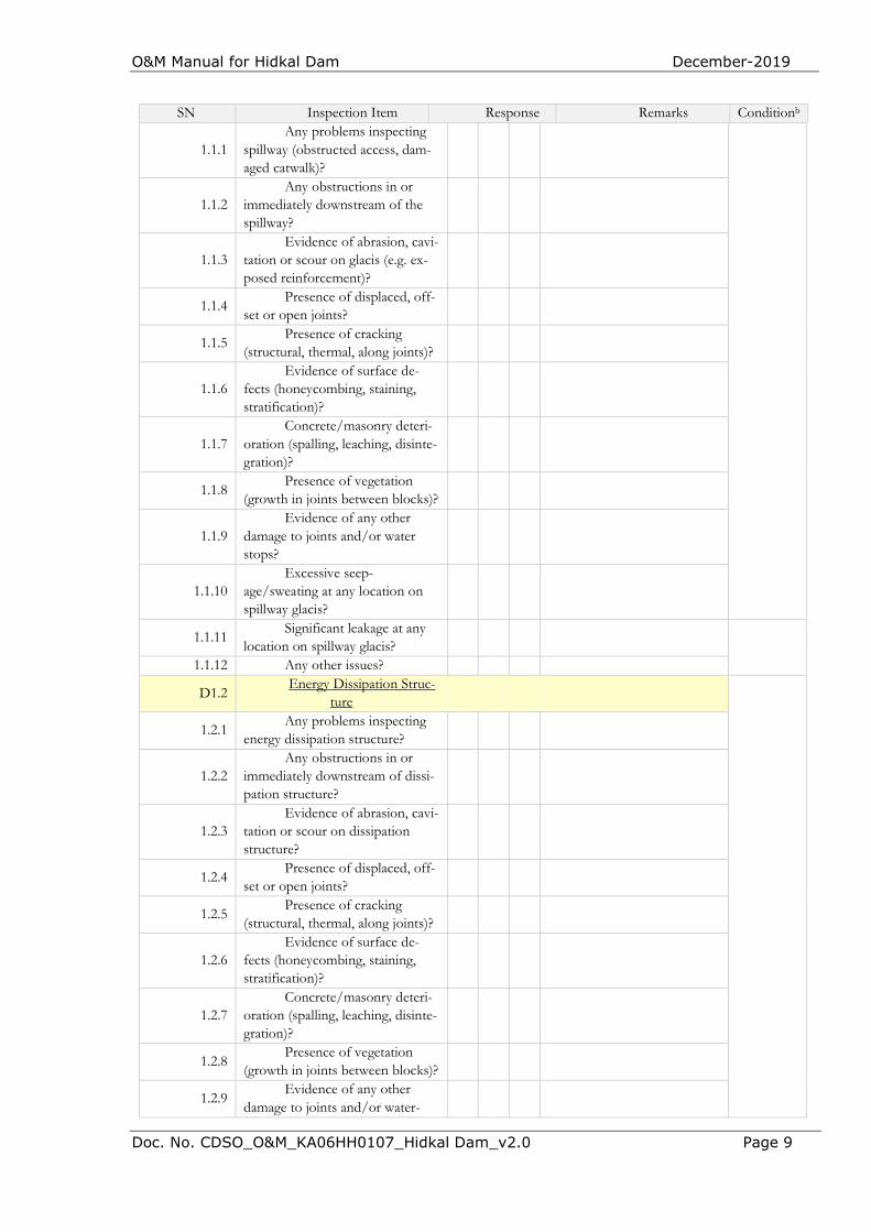
O&M Manual for Hidkal Dam December-2019
Doc. No. CDSO_O&M_KA06HH0107_Hidkal Dam_v2.0 Page 9
SN Inspection Item Response Remarks Conditionb
1.1.1 Any problems inspecting
spillway (obstructed access, dam-aged catwalk)?
1.1.2 Any obstructions in or
immediately downstream of the spillway?
1.1.3 Evidence of abrasion, cavi-
tation or scour on glacis (e.g. ex-posed reinforcement)?
1.1.4 Presence of displaced, off-
set or open joints?
1.1.5 Presence of cracking
(structural, thermal, along joints)?
1.1.6 Evidence of surface de-
fects (honeycombing, staining, stratification)?
1.1.7 Concrete/masonry deteri-
oration (spalling, leaching, disinte-gration)?
1.1.8 Presence of vegetation
(growth in joints between blocks)?
1.1.9 Evidence of any other
damage to joints and/or water stops?
1.1.10 Excessive seep-
age/sweating at any location on spillway glacis?
1.1.11 Significant leakage at any
location on spillway glacis?
1.1.12 Any other issues?
D1.2 Energy Dissipation Struc-
ture
1.2.1 Any problems inspecting
energy dissipation structure?
1.2.2 Any obstructions in or
immediately downstream of dissi-pation structure?
1.2.3 Evidence of abrasion, cavi-
tation or scour on dissipation structure?
1.2.4 Presence of displaced, off-
set or open joints?
1.2.5 Presence of cracking
(structural, thermal, along joints)?
1.2.6 Evidence of surface de-
fects (honeycombing, staining, stratification)?
1.2.7 Concrete/masonry deteri-
oration (spalling, leaching, disinte-gration)?
1.2.8 Presence of vegetation
(growth in joints between blocks)?
1.2.9 Evidence of any other
damage to joints and/or water-
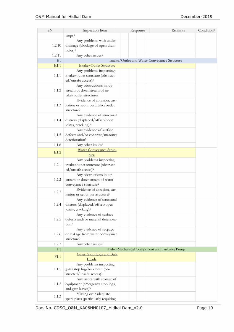
O&M Manual for Hidkal Dam December-2019
Doc. No. CDSO_O&M_KA06HH0107_Hidkal Dam_v2.0 Page 10
SN Inspection Item Response Remarks Conditionb
stops?
1.2.10 Any problems with under-
drainage (blockage of open drain holes)?
1.2.11 Any other issues? E1 Intake/Outlet and Water Conveyance Structure
E1.1 Intake/Outlet Structure
1.1.1 Any problems inspecting
intake/outlet structure (obstruct-ed/unsafe access)?
1.1.2 Any obstructions in, up-
stream or downstream of in-take/outlet structure?
1.1.3 Evidence of abrasion, cav-
itation or scour on intake/outlet structure?
1.1.4 Any evidence of structural
distress (displaced/offset/open joints, cracking)?
1.1.5 Any evidence of surface
defects and/or concrete/masonry deterioration?
1.1.6 Any other issues?
E1.2 Water Conveyance Struc-
ture
1.2.1 Any problems inspecting
intake/outlet structure (obstruct-ed/unsafe access)?
1.2.2 Any obstructions in, up-
stream or downstream of water conveyance structure?
1.2.3 Evidence of abrasion, cav-
itation or scour on structure?
1.2.4 Any evidence of structural
distress (displaced/offset/open joints, cracking)?
1.2.5 Any evidence of surface
defects and/or material deteriora-tion?
1.2.6 Any evidence of seepage
or leakage from water conveyance structure?
1.2.7 Any other issues? F1 Hydro-Mechanical Component and Turbine/Pump
F1.1 Gates, Stop Logs and Bulk
Heads
1.1.1 Any problems inspecting
gate/stop log/bulk head (ob-structed/unsafe access)?
1.1.2 Any issues with storage of
equipment (emergency stop logs, and gate leaves)?
1.1.3 Missing or inadequate
spare parts (particularly requiring
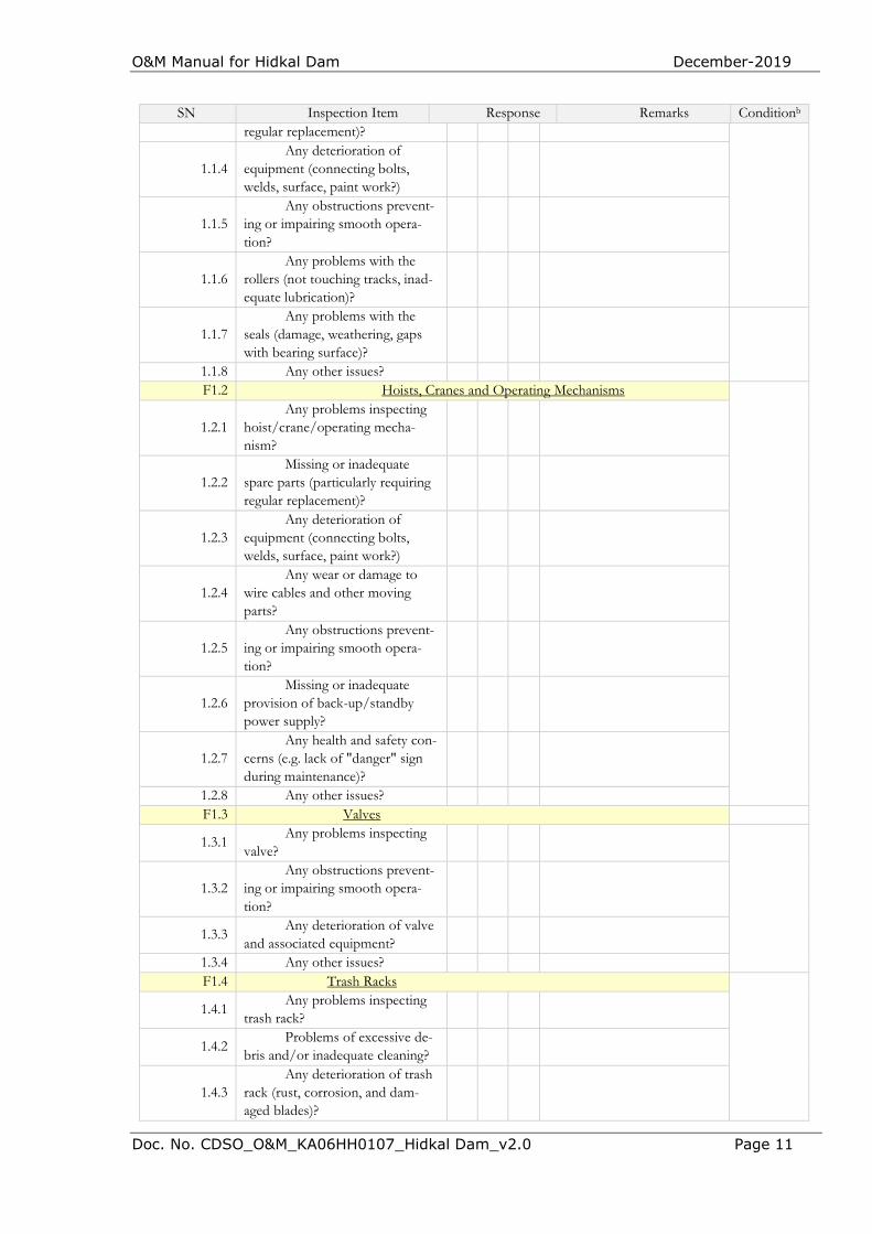
O&M Manual for Hidkal Dam December-2019
Doc. No. CDSO_O&M_KA06HH0107_Hidkal Dam_v2.0 Page 11
SN Inspection Item Response Remarks Conditionb
regular replacement)?
1.1.4 Any deterioration of
equipment (connecting bolts, welds, surface, paint work?)
1.1.5 Any obstructions prevent-
ing or impairing smooth opera-tion?
1.1.6 Any problems with the
rollers (not touching tracks, inad-equate lubrication)?
1.1.7 Any problems with the
seals (damage, weathering, gaps with bearing surface)?
1.1.8 Any other issues? F1.2 Hoists, Cranes and Operating Mechanisms
1.2.1 Any problems inspecting
hoist/crane/operating mecha-nism?
1.2.2 Missing or inadequate
spare parts (particularly requiring regular replacement)?
1.2.3 Any deterioration of
equipment (connecting bolts, welds, surface, paint work?)
1.2.4 Any wear or damage to
wire cables and other moving parts?
1.2.5 Any obstructions prevent-
ing or impairing smooth opera-tion?
1.2.6 Missing or inadequate
provision of back-up/standby power supply?
1.2.7 Any health and safety con-
cerns (e.g. lack of "danger" sign during maintenance)?
1.2.8 Any other issues? F1.3 Valves
1.3.1 Any problems inspecting
valve?
1.3.2 Any obstructions prevent-
ing or impairing smooth opera-tion?
1.3.3 Any deterioration of valve
and associated equipment?
1.3.4 Any other issues? F1.4 Trash Racks
1.4.1 Any problems inspecting
trash rack?
1.4.2 Problems of excessive de-
bris and/or inadequate cleaning?
1.4.3 Any deterioration of trash
rack (rust, corrosion, and dam-aged blades)?
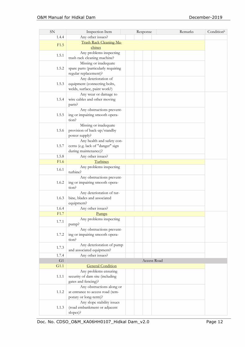
O&M Manual for Hidkal Dam December-2019
Doc. No. CDSO_O&M_KA06HH0107_Hidkal Dam_v2.0 Page 12
SN Inspection Item Response Remarks Conditionb
1.4.4 Any other issues?
F1.5 Trash Rack Cleaning Ma-
chines
1.5.1 Any problems inspecting
trash rack cleaning machine?
1.5.2 Missing or inadequate
spare parts (particularly requiring regular replacement)?
1.5.3 Any deterioration of
equipment (connecting bolts, welds, surface, paint work?)
1.5.4 Any wear or damage to
wire cables and other moving parts?
1.5.5 Any obstructions prevent-
ing or impairing smooth opera-tion?
1.5.6 Missing or inadequate
provision of back-up/standby power supply?
1.5.7 Any health and safety con-
cerns (e.g. lack of "danger" sign during maintenance)?
1.5.8 Any other issues? F1.6 Turbines
1.6.1 Any problems inspecting
turbine?
1.6.2 Any obstructions prevent-
ing or impairing smooth opera-tion?
1.6.3 Any deterioration of tur-
bine, blades and associated equipment?
1.6.4 Any other issues? F1.7 Pumps
1.7.1 Any problems inspecting
pump?
1.7.2 Any obstructions prevent-
ing or impairing smooth opera-tion?
1.7.3 Any deterioration of pump
and associated equipment?
1.7.4 Any other issues? G1 Access Road
G1.1 General Condition
1.1.1 Any problems ensuring
security of dam site (including gates and fencing)?
1.1.2 Any obstructions along or
at entrance to access road (tem-porary or long-term)?
1.1.3 Any slope stability issues
(road embankment or adjacent slopes)?
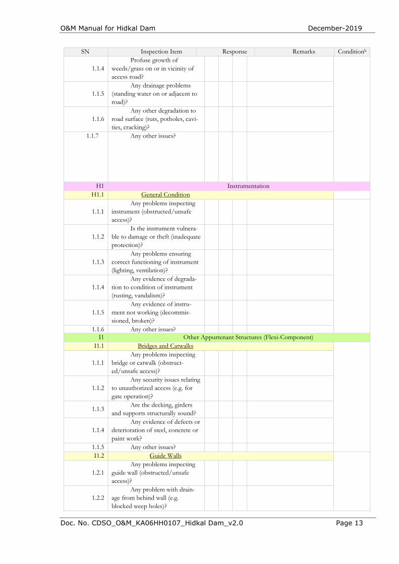
O&M Manual for Hidkal Dam December-2019
Doc. No. CDSO_O&M_KA06HH0107_Hidkal Dam_v2.0 Page 13
SN Inspection Item Response Remarks Conditionb
1.1.4 Profuse growth of
weeds/grass on or in vicinity of access road?
1.1.5 Any drainage problems
(standing water on or adjacent to road)?
1.1.6 Any other degradation to
road surface (ruts, potholes, cavi-ties, cracking)?
1.1.7 Any other issues?
H1 Instrumentation H1.1 General Condition
1.1.1 Any problems inspecting
instrument (obstructed/unsafe access)?
1.1.2 Is the instrument vulnera-
ble to damage or theft (inadequate protection)?
1.1.3 Any problems ensuring
correct functioning of instrument (lighting, ventilation)?
1.1.4 Any evidence of degrada-
tion to condition of instrument (rusting, vandalism)?
1.1.5 Any evidence of instru-
ment not working (decommis-sioned, broken)?
1.1.6 Any other issues? I1 Other Appurtenant Structures (Flexi-Component)
I1.1 Bridges and Catwalks
1.1.1 Any problems inspecting
bridge or catwalk (obstruct-ed/unsafe access)?
1.1.2 Any security issues relating
to unauthorized access (e.g. for gate operation)?
1.1.3 Are the decking, girders
and supports structurally sound?
1.1.4 Any evidence of defects or
deterioration of steel, concrete or paint work?
1.1.5 Any other issues? I1.2 Guide Walls
1.2.1 Any problems inspecting
guide wall (obstructed/unsafe access)?
1.2.2 Any problem with drain-
age from behind wall (e.g. blocked weep holes)?
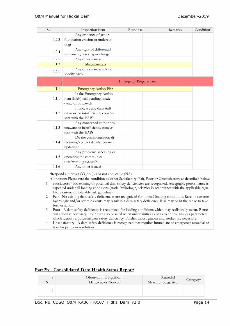
O&M Manual for Hidkal Dam December-2019
Doc. No. CDSO_O&M_KA06HH0107_Hidkal Dam_v2.0 Page 14
SN Inspection Item Response Remarks Conditionb
1.2.3 Any evidence of scour,
foundation erosion or undercut-ting?
1.2.4 Any signs of differential
settlement, cracking or tilting?
1.2.5 Any other issues? I1.3 Miscellaneous
1.3.1 Any other issues? (please
specify part)
1Emergency Preparedness
J1.1 Emergency Action Plan
1.1.1 Is the Emergency Action
Plan (EAP) still pending, inade-quate or outdated?
1.1.2 If not, are any dam staff
unaware or insufficiently conver-sant with the EAP?
1.1.3 Any concerned authorities
unaware or insufficiently conver-sant with the EAP?
1.1.4 Do the communication di-
rectories/contact details require updating?
1.1.5 Any problems accessing or
operating the communica-tion/warning system?
1.1.6 Any other issues?
aRespond either yes (Y), no (N) or not applicable (NA). bCondition: Please rate the condition as either Satisfactory, Fair, Poor or Unsatisfactory as described below:
1. Satisfactory - No existing or potential dam safety deficiencies are recognized. Acceptable performance is expected under all loading conditions (static, hydrologic, seismic) in accordance with the applicable regu-latory criteria or tolerable risk guidelines.
2. Fair - No existing dam safety deficiencies are recognized for normal loading conditions. Rare or extreme hydrologic and/or seismic events may result in a dam safety deficiency. Risk may be in the range to take further action.
3. Poor - A dam safety deficiency is recognized for loading conditions which may realistically occur. Reme-dial action is necessary. Poor may also be used when uncertainties exist as to critical analysis parameters which identify a potential dam safety deficiency. Further investigations and studies are necessary.
4. Unsatisfactory - A dam safety deficiency is recognized that requires immediate or emergency remedial ac-tion for problem resolution.
Part 2b – Consolidated Dam Health Status Report:
SN
Observations/Significant Deficiencies Noticed
Remedial Measures Suggested
Categorya
1

O&M Manual for Hidkal Dam December-2019
Doc. No. CDSO_O&M_KA06HH0107_Hidkal Dam_v2.0 Page 15
2
3
4
aCategory I – deficiencies which may lead to failure; Category II – major deficiencies requiring prompt remedial measures; Category III – minor remedial measures which are rectifiable during the year

O&M Manual for Hidkal Dam December-2019
Doc. No. CDSO_O&M_KA06HH0107_Hidkal Dam_v2.0 Page 16
APPENDIX 7 - GLOSSARY
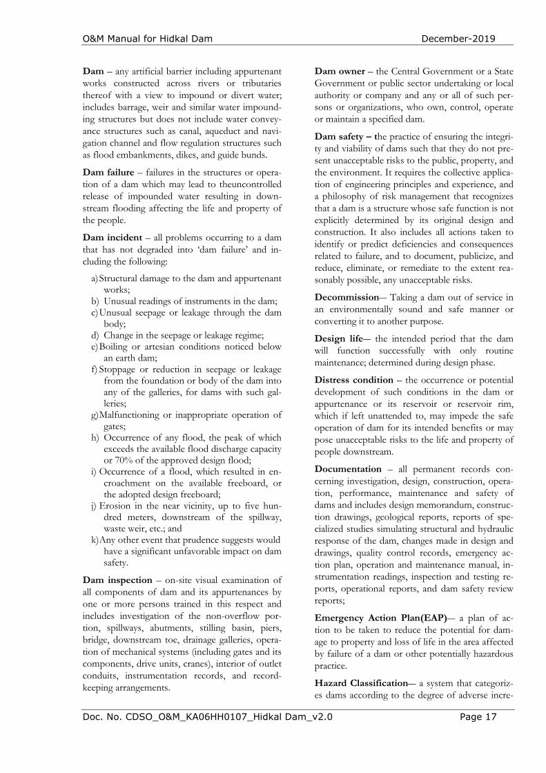
O&M Manual for Hidkal Dam December-2019
Doc. No. CDSO_O&M_KA06HH0107_Hidkal Dam_v2.0 Page 17
Dam – any artificial barrier including appurtenant works constructed across rivers or tributaries thereof with a view to impound or divert water; includes barrage, weir and similar water impound-ing structures but does not include water convey-ance structures such as canal, aqueduct and navi-gation channel and flow regulation structures such as flood embankments, dikes, and guide bunds.
Dam failure – failures in the structures or opera-tion of a dam which may lead to theuncontrolled release of impounded water resulting in down-stream flooding affecting the life and property of the people.
Dam incident – all problems occurring to a dam that has not degraded into ‘dam failure’ and in-cluding the following:
a) Structural damage to the dam and appurtenant works;
b) Unusual readings of instruments in the dam; c) Unusual seepage or leakage through the dam
body; d) Change in the seepage or leakage regime; e) Boiling or artesian conditions noticed below
an earth dam; f) Stoppage or reduction in seepage or leakage
from the foundation or body of the dam into any of the galleries, for dams with such gal-leries;
g) Malfunctioning or inappropriate operation of gates;
h) Occurrence of any flood, the peak of which exceeds the available flood discharge capacity or 70% of the approved design flood;
i) Occurrence of a flood, which resulted in en-croachment on the available freeboard, or the adopted design freeboard;
j) Erosion in the near vicinity, up to five hun-dred meters, downstream of the spillway, waste weir, etc.; and
k) Any other event that prudence suggests would have a significant unfavorable impact on dam safety.
Dam inspection – on-site visual examination of all components of dam and its appurtenances by one or more persons trained in this respect and includes investigation of the non-overflow por-tion, spillways, abutments, stilling basin, piers, bridge, downstream toe, drainage galleries, opera-tion of mechanical systems (including gates and its components, drive units, cranes), interior of outlet conduits, instrumentation records, and record-keeping arrangements.
Dam owner – the Central Government or a State Government or public sector undertaking or local authority or company and any or all of such per-sons or organizations, who own, control, operate or maintain a specified dam.
Dam safety – the practice of ensuring the integri-ty and viability of dams such that they do not pre-sent unacceptable risks to the public, property, and the environment. It requires the collective applica-tion of engineering principles and experience, and a philosophy of risk management that recognizes that a dam is a structure whose safe function is not explicitly determined by its original design and construction. It also includes all actions taken to identify or predict deficiencies and consequences related to failure, and to document, publicize, and reduce, eliminate, or remediate to the extent rea-sonably possible, any unacceptable risks.
Decommission― Taking a dam out of service in an environmentally sound and safe manner or converting it to another purpose.
Design life― the intended period that the dam will function successfully with only routine maintenance; determined during design phase.
Distress condition – the occurrence or potential development of such conditions in the dam or appurtenance or its reservoir or reservoir rim, which if left unattended to, may impede the safe operation of dam for its intended benefits or may pose unacceptable risks to the life and property of people downstream.
Documentation – all permanent records con-cerning investigation, design, construction, opera-tion, performance, maintenance and safety of dams and includes design memorandum, construc-tion drawings, geological reports, reports of spe-cialized studies simulating structural and hydraulic response of the dam, changes made in design and drawings, quality control records, emergency ac-tion plan, operation and maintenance manual, in-strumentation readings, inspection and testing re-ports, operational reports, and dam safety review reports;
Emergency Action Plan(EAP)― a plan of ac-tion to be taken to reduce the potential for dam-age to property and loss of life in the area affected by failure of a dam or other potentially hazardous practice.
Hazard Classification― a system that categoriz-es dams according to the degree of adverse incre-
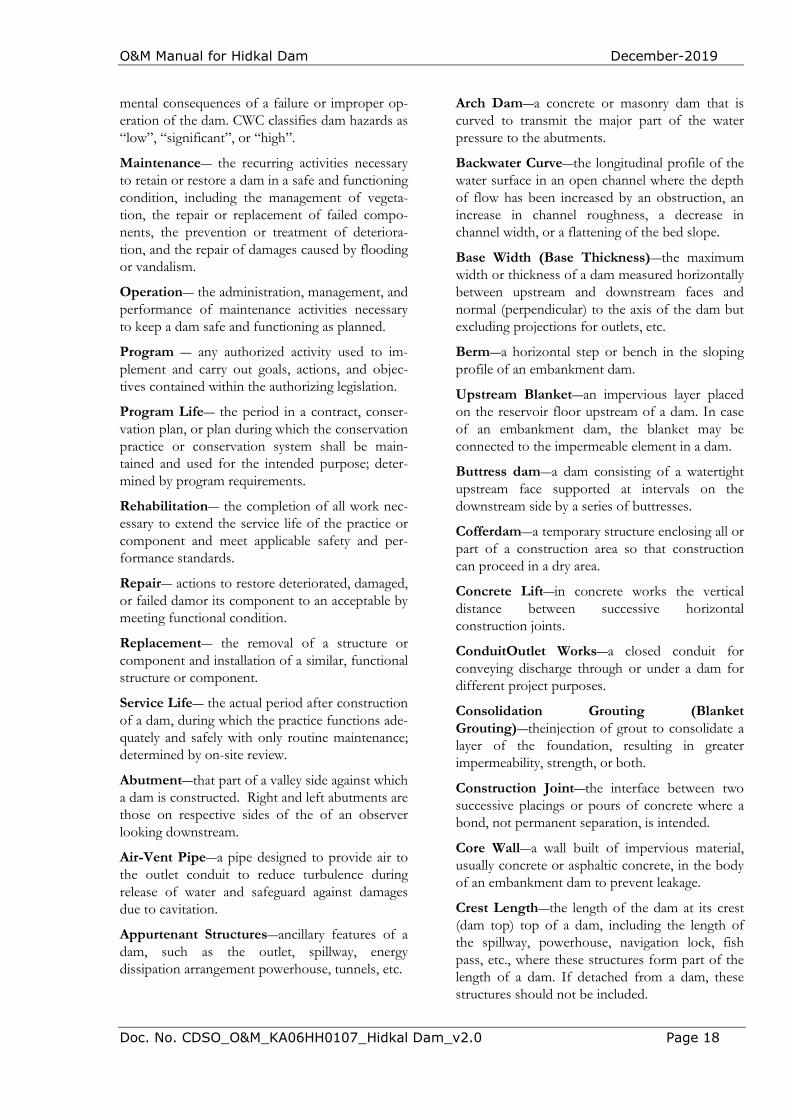
O&M Manual for Hidkal Dam December-2019
Doc. No. CDSO_O&M_KA06HH0107_Hidkal Dam_v2.0 Page 18
mental consequences of a failure or improper op-eration of the dam. CWC classifies dam hazards as “low”, “significant”, or “high”.
Maintenance― the recurring activities necessary to retain or restore a dam in a safe and functioning condition, including the management of vegeta-tion, the repair or replacement of failed compo-nents, the prevention or treatment of deteriora-tion, and the repair of damages caused by flooding or vandalism.
Operation― the administration, management, and performance of maintenance activities necessary to keep a dam safe and functioning as planned.
Program ― any authorized activity used to im-plement and carry out goals, actions, and objec-tives contained within the authorizing legislation.
Program Life― the period in a contract, conser-vation plan, or plan during which the conservation practice or conservation system shall be main-tained and used for the intended purpose; deter-mined by program requirements.
Rehabilitation― the completion of all work nec-essary to extend the service life of the practice or component and meet applicable safety and per-formance standards.
Repair― actions to restore deteriorated, damaged, or failed damor its component to an acceptable by meeting functional condition.
Replacement― the removal of a structure or component and installation of a similar, functional structure or component.
Service Life― the actual period after construction of a dam, during which the practice functions ade-quately and safely with only routine maintenance; determined by on-site review.
Abutment―that part of a valley side against which a dam is constructed. Right and left abutments are those on respective sides of the of an observer looking downstream.
Air-Vent Pipe―a pipe designed to provide air to the outlet conduit to reduce turbulence during release of water and safeguard against damages due to cavitation.
Appurtenant Structures―ancillary features of a dam, such as the outlet, spillway, energy dissipation arrangement powerhouse, tunnels, etc.
Arch Dam―a concrete or masonry dam that is curved to transmit the major part of the water pressure to the abutments.
Backwater Curve―the longitudinal profile of the water surface in an open channel where the depth of flow has been increased by an obstruction, an increase in channel roughness, a decrease in channel width, or a flattening of the bed slope.
Base Width (Base Thickness)―the maximum width or thickness of a dam measured horizontally between upstream and downstream faces and normal (perpendicular) to the axis of the dam but excluding projections for outlets, etc.
Berm―a horizontal step or bench in the sloping profile of an embankment dam.
Upstream Blanket―an impervious layer placed on the reservoir floor upstream of a dam. In case of an embankment dam, the blanket may be connected to the impermeable element in a dam.
Buttress dam―a dam consisting of a watertight upstream face supported at intervals on the downstream side by a series of buttresses.
Cofferdam―a temporary structure enclosing all or part of a construction area so that construction can proceed in a dry area.
Concrete Lift―in concrete works the vertical distance between successive horizontal construction joints.
ConduitOutlet Works―a closed conduit for conveying discharge through or under a dam for different project purposes.
Consolidation Grouting (Blanket Grouting)―theinjection of grout to consolidate a layer of the foundation, resulting in greater impermeability, strength, or both.
Construction Joint―the interface between two successive placings or pours of concrete where a bond, not permanent separation, is intended.
Core Wall―a wall built of impervious material, usually concrete or asphaltic concrete, in the body of an embankment dam to prevent leakage.
Crest Length―the length of the dam at its crest (dam top) top of a dam, including the length of the spillway, powerhouse, navigation lock, fish pass, etc., where these structures form part of the length of a dam. If detached from a dam, these structures should not be included.
O&M Manual for Hidkal Dam December-2019
Doc. No. CDSO_O&M_KA06HH0107_Hidkal Dam_v2.0 Page 19
Crest of dam―Used to indicate the “top of dam”. To avoid confusion to indicate the crest of spillway and top of dam may be used.
Culvert―a drain or waterway built under a road, railway, or embankment, usually consisting of a pipe or covered conduits
Cutoff―an impervious construction or material which reduces seepage through the foundation material.
Cutoff trench―an excavation later to be filled with impervious material to form a cutoff.
Cutoff wall―a wall of impervious material (e.g., concrete, asphaltic concrete, steel-sheet piling) built into the foundation to reduce seepage under the dam.
Dead storage―the storage that lies below the invert of the lowest outlet and that, therefore, cannot be withdrawn from the reservoir.
Design flood―see spillway design flood.
Diaphragm―see membrane.
Dike (Levee)―a long low embankment whose height is usually less than 5 m and whose length is more than 10 times the maximum height. Usually applied to embankments or structures built to protect land from flooding. If built of concrete or masonry, the structure is usually referred to as a flood wall. Also, used to describe embankments that block areas on a reservoir rim that are lower than the top of the main dam and that are quite long. In the Mississippi River basin, where the old French word levee has survived, the term now applies to flood-protecting embankments whose height can average up to 15 m.
Diversion channel, canal, or tunnel―a waterway used to divert water from its natural course. These terms are generally applied to temporary structures such as those designed to bypass water around a dam site during construction. “Channel’ is normally used instead of “canal” when the waterway is short.Occasionally these terms are applied to permanent structures.
Drainage area―an area that drains naturally to a point on a river.
Drainage layer or blanket―a layer of permeable material in a dam to relieve pore pressure or to facilitate drainage of fill.
Relief well―vertical wells or boreholes, constructed downstream of an embankment dam to relieve the pressure from confined pervious layers in foundation overlaid by an impervious layer to arrest boiling.
Drawdown―the lowering of water surface level due to release of water from a reservoir.
Earthen dam or earth filleddam―see embankment dam.
Embankment dam (Fill dam)― any dam constructed of excavated natural materials.
Earth dam (Earth filldam)―An embankment dam in which more than 50 percent of the total volume is formed of compacted fine-grained material obtained from a borrow area.
Homogeneous earth filldam― an embankment dam constructed of similar earth material throughout, except internal drains or drainage blankets; distinguished from a zoned earth fill dam.
Hydraulic fill dam―an embankment dam constructed of materials, often dredged, that are conveyed and placed by suspension in flowing water.
Rock fill dam―an embankment dam in which more than 50 percent of the total volume comprises compacted or dumped pervious natural or crushed rock.
Rolled fill dam―an embankment dam of earth or rock in which the material is placed in layers and compacted using rollers or rolling equipment.
Zoned embankment dam―an embankment damcomposed of zones of materials selected for different degrees of porosity, permeability and density.
Emergency spillway―see spillway.
Face―the external surface of a structure, e.g., the surface of a wall of a dam.
Failure―the uncontrolled release of water from a dam.
Filter (filter zone)―A band or zone of granular material that is incorporated into a dam and is graded (either naturally or by selection) to allow seepage to flow across or down the filter without causing the migration of material from zones adjacent to it.
O&M Manual for Hidkal Dam December-2019
Doc. No. CDSO_O&M_KA06HH0107_Hidkal Dam_v2.0 Page 20
Flashboards―a length of timber, concrete, or steel placed on the crest of a spillway to raise the retention water level but that may be quickly removed in the event of a flood, either by a tripping device or by deliberately designed failure of the flashboard or its supports.
Floodplain―an area adjoining a body of water or natural stream that has been, or may be, covered by flood water.
Floodplain management―a management program to reduce the consequences of flooding, either by natural runoff or by dam failure, to existing and future properties in a floodplain.
Flood routing―the determination of the attenuating effect of storage on a flood passing through a valley, channel, or reservoir.
Flood surcharge―the volume or space in a reservoir between the controlled retention water level (Full Reservoir Level) and the maximum water level. Flood surcharge cannot be retained in the reservoir but will flow over the spillway until the controlled retention water level is reached.
Flood wall―a concrete wall constructed adjacent to a stream to prevent flooding of property on the landward side of the wall, normally constructed in lieu of or to supplement a levee where the land required for levee construction is expensive or not available.
Foundation of dam―the natural material on which the dam structure is placed.
Freeboard―the vertical distance between a stated reservoir level and the top of a dam.Normal freeboard is the vertical distance between Full Reservoir Level (FRL) and the top of the dam. Minimum freeboard is the verticaldistance between the Maximum Water Level (MWL) and the top of the dam.
Gallery―(a) a passageway within the body of a dam or abutment, hence the terms grouting gallery, inspection galleryand drainage gallery (b) a long and rather narrow hall, hence the following terms for a power plant viz.valve gallery, transformer gallery andbus bar gallery.
Gate―a device in which a leaf or member is moved across the waterway from an external position to control or stop the flow.
Bulkhead gate―a gate used either for temporary closure of a channel or conduit to empty it for inspection or maintenance or for closure against
flowing water when the head difference is small, e.g., for diversion tunnel closure. Although a bulkhead gate is usually opened and closed under nearly balanced pressures, it nevertheless may be capable of withstanding a high pressure differential when in the closed position.
Crest gate (spillway gate)―a gate on the crest of a spillway to control overflow or reservoir water level.
Emergency gate―a standby or reserve gate which is lowers only for repairing / servicing of the service gate.
Fixed wheel gate (fixed-roller gate, fixed-axle gate)―a gate having wheels or rollers mounted on the end posts of the gate. The wheels move against rails fixed in side grooves or gate guides.
Flap gate―a gate hinged along one edge, usually either the top or bottom edge. Examples of bottom-hinged flap gates are tilting gates and belly gates, so called due to their shape in cross-section.
Flood gate―a gate to control flood release from a reservoir.
Guard gate(guard valve)―a gate or valve that operates fully open or closed. It may function as a secondary device for shutting off the flow of water in case the primary closure device becomes inoperable but is usually operated under conditions of balanced pressure and no flow.
Outlet gate―a gate controlling the outflow of water from a reservoir.
Radial gate (Tainter gate)―a gate with a curved upstream plate and radial arms hinged to piers or other supporting structures.
Service/Regulating gate(regulating valve)―a gate or valve that operates under full pressure and flow to throttle and vary the rate of discharge.
Slide gate (sluice gate)―a gate that can be opened or closed by sliding it in supporting guides.
Gravity dam―a dam constructed of concrete, masonry, or both that relies on its weight for stability.
Grout cap―a pad or wall constructed to facilitate pressure grouting of the grout curtain beneath it.
Grout curtain (grout cutoff)―a barrier produced byinjecting grout into a vertical zone, usually
O&M Manual for Hidkal Dam December-2019
Doc. No. CDSO_O&M_KA06HH0107_Hidkal Dam_v2.0 Page 21
narrow horizontally, in the foundation to reduce seepage under a dam.
Height above lowest foundation―the maximum heightfrom the lowest point of the general foundation to the top of the dam.
Hydraulic height―the height to which water rises behind a dam and the difference between the lowest point in the original streambed at the axis of the dam and the maximum controllable water surface.
Hydrograph―a graphic representation of discharge, stage, or other hydraulic property with respect to time for a point on a stream. (At times the term is applied to the phenomenon the graphic representation describes; hence a flood hydrograph is the passage of a flood discharge past the observation point.)
Inclinometer―an instrument, usually consisting of a metal or plastic tube inserted in a drill hole and a sensitized monitor either lowered into the tube or fixed within it. The monitor measures at different points the tube’s inclination to the vertical. By integration, the lateral position at various levels of the tube may be found relative to a point, usually the top or bottom of the tube, assumed to be fixed. The system may be used to measure settlement.
Intake―any structure in a reservoir, dam, or river through which water can be drawn into an aqueduct.
Internal Erosion―see piping.
Inundation map―a map delineating the area that would be inundated in case of a failure.
Leakage―Uncontrolled loss of water by flow through a hole or crack.
Lining― a coating of asphaltic concrete, reinforced or unreinforced concrete, shotcrete, rubber or plastic on a canal, tunnel etc. to provide water tightness, prevent erosion, reduce friction, or support the periphery of structure. May also refer to lining, such as steel or concrete, of outlet pipe or conduit.
Low-level outlet (bottom outlet)―an opening at a lowlevel from a reservoir generally used for emptying or for scouring sediment and sometimes for irrigation releases.
Masonry dam―a dam constructed mainly of stone, brick, or concrete blocks that may or may
not be joined with mortar. A dam having only a masonry facing should not be referred to as a masonry dam.
Maximum cross-section of dam―a cross-section of a dam at the point of its maximum height.
Maximum water level―the maximum water level, including flood surcharge, the dam is designed to withstand.
Membrane (Diaphragm)―a sheet or thin zone or facing made of a flexible material, sometimes referred to as a diaphragm wall or diaphragm.
Minimum operating level―the lowest level to which the reservoir is drawn down under normal operating conditions.
Morning glory spillway―see spillway.
Full Reservoir Level (FRL)/Normal water level―for a reservoir with un-gated spillway it is the spillway crest level. For a reservoir, whose outflow is controlled wholly or partly by movable gates, siphons or other means, it is the maximum level to which water can be stored under normal operating conditions, exclusive of any provision for flood surcharge.
One-Hundred Year (100-Year) Exceedance Interval― the flood magnitude expected to be equaled or exceeded on the average of once in 100 years. It may also be expressed as an exceedance frequency, i.e. a percent chance of being exceeded in any given year.
Outlet―an opening through which water can be freely discharged from a reservoir.
Overflow dam―a dam designed to be overtopped.
Parapet Wall―a solid wall built along the top of a dam for ornament, for the safety of vehicles and pedestrians, or to prevent overtopping.
Peak Flow―the maximum instantaneous discharge that occurs during a flood. It coincides with the peak of a flood hydrograph.
Pervious Zone―a part of the cross-section of an embankment dam comprising material of high permeability.
Phreatic Surface―thetop most flow line in an embankment dam.
Piezometer―an instrument for measuring pore water pressure within soil, rock, or concrete.
O&M Manual for Hidkal Dam December-2019
Doc. No. CDSO_O&M_KA06HH0107_Hidkal Dam_v2.0 Page 22
Piping―the progressive development of internal erosion by seepage, appearing downstream as a hole or seam discharging water that contains soil particles.
Pore Pressure―the interstitial pressure of water within a mass of soil, rock, or concrete.
Pressure Cell―an instrument for measuring pressure within a mass of soil, rock, or concrete or at an interface between one and the other.
Pressure Relief Pipes―Pipes used to relieve uplift or pore water pressure in a dam’s foundation or structure.
Probable Maximum Flood (PMF)―a flood that would result from the most severe combination of critical meteorologic and hydrologic conditions possible in the region.
Probable Maximum Precipitation (PMP)―the maximum amount and duration of precipitation that can be expected to occur on a drainage basin.
Pumped storage reservoir―a reservoir filled entirely or mainly with water pumped from outside its natural drainage area.
Regulating dam―a dam impounding a reservoir from which water is released to regulate
Reservoir area―the surface area of a reservoir when filled to controlled retention level.
Reservoir routing―the computation by which the interrelated effects of the inflow hydrograph, reservoir storage, and discharge from the reservoir are evaluated.
Reservoir surface―the surface of a reservoir at any level.
Riprap―a layer of large stones, broken rock, or precast blocks placed randomly on the upstream slope of an embankment dam, on a reservoir shore, or on the sides of a channel as a protection against wave action. Large riprap is sometimes referred to as armoring.
Risk assessment―as applied to dam safety, the process of identifying the likelihood and consequences of dam failure to provide the basis for informed decisions on a course of action.
Rock fill Dam―see embankment dam.
Roll Crete or Roller-Compacted ConcreteAno-slump concrete that can be hauled in dump trucks, spread with a bulldozer or grader, and compacted with a vibratory roller.
Seepage―the interstitial movement of water that may take place through a dam, its foundation, or its abutments.
Sill―(a) A submerged structure across a river to control the water level upstream. (b) The crest of a spillway. (c) A horizontal gate seating, made of wood, stone, concrete or metal at the invert of any opening or gap in a structure, hence the expressions gate sill and stop log sill.
Slope―(a) the side of a hill or mountain. (b) The inclined face of a cutting or canal or embankment. (c) Inclination from the horizontal. In the United States, it is measured as the ratio of the number of units of horizontal distance to the number of corresponding units of vertical distance. The term is used in English for any inclination and is expressed as a percentage when the slope is gentle, in which case the term gradient is also used.
Slope Protection―the protection of a slope against wave action or erosion.
Sluiceway―see low-level outlet.
Spillway―a structure over or through which flood flows are discharged. If the flow is controlled by gates, it is a controlled spillway; if the elevation of the spillway crest is the only control, it is an uncontrolled spillway.
Auxiliary Spillway (Emergency Spillway)―a secondary spillway designed to operate only during exceptionally large floods.
Fuse-Plug Spillway―an auxiliary or emergency spillway comprising a low embankment or a natural saddle designed to be overtopped and eroded away during a rare and exceptionally large flood.
Primary Spillway(Principal Spillway)―the principal or first-used spillway during flood flows.
Shaft Spillway (Morning Glory Spillway)―a vertical or inclined shaft into which flood water spills and then is conducted through, under, or around a dam by means of a conduit or tunnel. If the upper part of the shaft is splayed out and terminates in a circular horizontal weir, it is termed a “bell mouth” or “morning glory” spillway.
Side Channel Spillway―a spillway whose crest is roughly parallel to the channel immediately downstream of the spillway.
Siphon Spillway―a spillway with one or more siphons built at crest level. This type of spillway is
O&M Manual for Hidkal Dam December-2019
Doc. No. CDSO_O&M_KA06HH0107_Hidkal Dam_v2.0 Page 23
sometimes used for providing automatic surface-level regulation within narrow limits or when considerable discharge capacity is necessary within a short period.
Spillway Channel (Spillway Tunnel)―a channel or tunnel conveying water from the spillway to the river downstream.
Stilling Basin―a basin constructed to dissipate the energy of fast-flowing water, e.g., from a spillway or bottom outlet, and to protect the riverbed from erosion.
Stop logs―large logs or timber or steel beams placed on top of each other with their ends held in guides on each side of a channel or conduit providing a cheaper or easily handled temporary closure than a bulkhead gate.
Storage―the retention of water or delay of runoff either by planned operation, as in a reservoir, or by temporary filling of overflow areas, as in the progression of a flood crest through a natural stream channel.
Tailrace―the tunnel, channel or conduit that conveys the discharge from the turbine to the river, hence the terms tailrace tunnel and tailrace canal.
Tail water Level―the level of water in the tailrace at the nearest free surface to the turbine or in the discharge channel immediately downstream of the dam.
Toe of Dam―the junction of the downstream face of a dam with the ground surface, referred to as the downstream toe. For an embankment dam the junction of upstream face with ground surface is called the upstream toe.
Top of Dam―the elevation of the uppermost surface of a dam, usually a road or walkway, excluding any parapet wall, railings, etc.
Top Thickness (Top Width)―the thickness or width of a dam at the level of the top of the dam.
In general, “thickness” is used for gravity and arch dams, “width” for other dams.
Transition Zone (Semi-pervious Zone)―a part of the cross-section of a zoned embankment dam comprising material of intermediate size between that of an impervious zone and that of a permeable zone.
Trash rack―a screen located at an intake to prevent the ingress of debris.
Tunnel―a long underground excavation usually having a uniform cross-section. Types of tunnel include: headrace tunnel, pressure tunnel, collecting tunnel, diversion tunnel, power tunnel, tailrace tunnel, navigation tunnel, access tunnel, scour tunnel, draw-off tunnel, and spillway tunnel.
Under seepage―the interstitial movement of water through a foundation.
Uplift―the upward pressure in the pores of a material (interstitial pressure) or on the base of a structure.
Upstream Blanket―see blanket.
Valve―a device fitted to a pipeline or orifice in which the closure member is either rotated or moved transversely or longitudinally in the waterway to control or stop the flow.
Water stop―a strip of metal, rubber or other material used to prevent leakage through joints between adjacent sections of concrete.
Weir―(a) a low dam or wall built across a stream to raise the upstream water level, called fixed-crest weir when uncontrolled. (b) A structure built across a stream or channel for measuring flow, sometimes called a measuring weir or gauging weir. Types of weir include broad-crested weir, sharp-crested weir, drowned weir, and submerged weir.

O&M Manual for Hidkal Dam December-2019
Doc. No. CDSO_O&M_DS_01_v2.0 Page24
THIS PAGE LEFT BLANK INTENTIONALLY
O&M Manual for Hidkal Dam December-2019
Doc. No. CDSO_O&M_DS_01_v2.0 Page25
Central Dam Safety Organisation
Central Water Commission
Vision
To remain as a premier organisation with best technical and managerial ex-pertise for providing advisory services on matters relating to dam safety.
Mission
To provide expert services to State Dam Safety Organisations, dam owners, dam operating agencies and others concerned for ensuring safe functioning of dams with a view to protect human life, property and the environment.
Values
Integrity: Act with integrity and honesty in all our actions and practices.
Commitment: Ensure good working conditions for employees and encour-age professional excellence.
Transparency: Ensure clear, accurate and complete information in commu-nications with stakeholders and take all decisions openly based on reliable information.
Quality of service: Provide state-of-the-art technical and managerial ser-vices within agreed time frame.
Striving towards excellence: Promote continual improvement as an integral part of our working and strive towards excellence in all our endeavours.
Quality Policy
We provide technical and managerial assistance to dam owners and State Dam Safety Organizations for proper surveillance, inspection, operation and maintenance of all dams and appurtenant works in India to ensure safe func-tioning of dams and protecting human life, property and the environment.
We develop and nurture competent manpower and equip ourselves with state-of-the-art technical infrastructure to provide expert services to all stakeholders.
We continually improve our systems, processes and services to ensure satis-faction of our customers.
Copyright © 2022 FDOKUMEN