Online Help
337
Online Help Issue 01 Date 2020-05-30 HUAWEI TECHNOLOGIES CO., LTD.
-
Upload
khangminh22 -
Category
Documents
-
view
2 -
download
0
Transcript of Online Help

Online Help
Issue 01
Date 2020-05-30
HUAWEI TECHNOLOGIES CO., LTD.

Copyright © Huawei Technologies Co., Ltd. 2020. All rights reserved.
No part of this document may be reproduced or transmitted in any form or by any means without priorwritten consent of Huawei Technologies Co., Ltd. Trademarks and Permissions
and other Huawei trademarks are trademarks of Huawei Technologies Co., Ltd.All other trademarks and trade names mentioned in this document are the property of their respectiveholders. NoticeThe purchased products, services and features are stipulated by the contract made between Huawei andthe customer. All or part of the products, services and features described in this document may not bewithin the purchase scope or the usage scope. Unless otherwise specified in the contract, all statements,information, and recommendations in this document are provided "AS IS" without warranties, guaranteesor representations of any kind, either express or implied.
The information in this document is subject to change without notice. Every effort has been made in thepreparation of this document to ensure accuracy of the contents, but all statements, information, andrecommendations in this document do not constitute a warranty of any kind, express or implied.
Issue 01 (2020-05-30) Copyright © Huawei Technologies Co., Ltd. i

Contents
1 Prerequisites............................................................................................................................. 1
2 Feature Updates.......................................................................................................................2
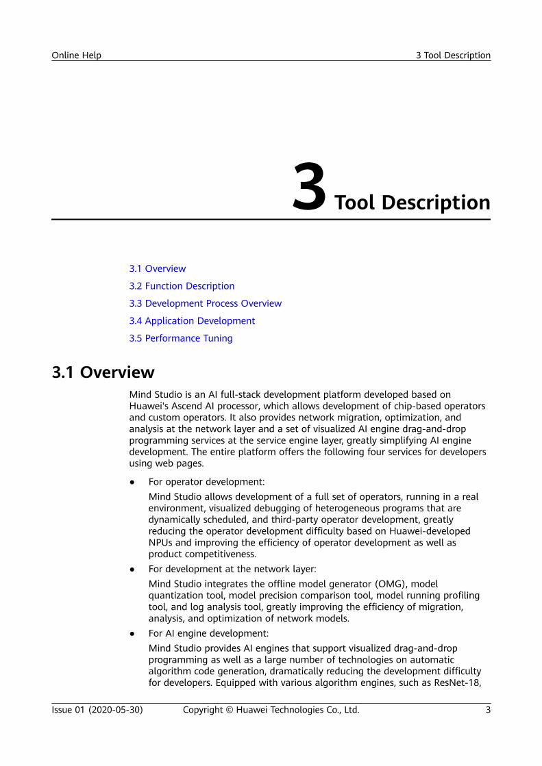
3 Tool Description....................................................................................................................... 33.1 Overview.................................................................................................................................................................................... 33.2 Function Description.............................................................................................................................................................. 43.3 Development Process Overview......................................................................................................................................... 53.4 Application Development..................................................................................................................................................... 63.4.1 Project Management.......................................................................................................................................................... 63.4.2 Graphical Service Orchestration......................................................................................................................................83.4.3 Model Management......................................................................................................................................................... 103.4.4 Offline Model Conversion...............................................................................................................................................113.4.5 Development of Custom Operators ...........................................................................................................................143.4.6 Dataset Management...................................................................................................................................................... 153.5 Performance Tuning............................................................................................................................................................. 173.5.1 Performance Profiler........................................................................................................................................................ 173.5.2 Log Analysis.........................................................................................................................................................................193.5.3 Black Box.............................................................................................................................................................................. 20
4 Basic Operations.................................................................................................................... 214.1 Introduction............................................................................................................................................................................ 214.1.1 Statement.............................................................................................................................................................................214.1.2 Overview...............................................................................................................................................................................214.1.3 Function Description........................................................................................................................................................ 224.2 User Management................................................................................................................................................................ 234.2.1 Logging In............................................................................................................................................................................ 244.2.2 Resetting the Password................................................................................................................................................... 254.2.3 Changing the Password................................................................................................................................................... 264.2.4 Logging Out........................................................................................................................................................................ 274.2.5 Querying Security Logs....................................................................................................................................................274.3 Project Management........................................................................................................................................................... 274.3.1 Project Introduction.......................................................................................................................................................... 274.3.2 Basic Project Operations................................................................................................................................................. 284.3.2.1 Creating/Deleting a Project........................................................................................................................................ 28
Online Help Contents
Issue 01 (2020-05-30) Copyright © Huawei Technologies Co., Ltd. ii

4.3.2.2 Uploading/Downloading a Project........................................................................................................................... 304.3.2.3 Creating/Deleting a File............................................................................................................................................... 314.3.2.4 Uploading a File/Folder............................................................................................................................................... 314.3.2.5 Opening a Project.......................................................................................................................................................... 324.3.2.6 Closing a Project............................................................................................................................................................. 354.3.2.7 Compiling a Project....................................................................................................................................................... 354.3.2.8 Running a Project........................................................................................................................................................... 464.3.2.9 Supported File Formats................................................................................................................................................474.3.3 Basic Node Operations.................................................................................................................................................... 484.3.3.1 Service Node Overview................................................................................................................................................ 484.3.3.2 Placing a Node................................................................................................................................................................ 524.3.3.3 Deleting a Node............................................................................................................................................................. 534.3.3.4 Copying and Pasting a Node......................................................................................................................................554.3.3.5 Setting the Properties of a Node.............................................................................................................................. 574.3.3.6 Establishing a Connection........................................................................................................................................... 624.3.3.7 Saving Nodes................................................................................................................................................................... 634.3.3.8 Generating a .cpp File...................................................................................................................................................644.4 Dataset Management......................................................................................................................................................... 644.4.1 Overview...............................................................................................................................................................................644.4.2 Dataset Management in the Projects Explorer Window......................................................................................654.4.2.1 Viewing the Datasets.................................................................................................................................................... 654.4.2.2 Importing a Dataset...................................................................................................................................................... 674.4.2.3 Viewing the Dataset Properties.................................................................................................................................834.4.2.4 Generating a .cpp File...................................................................................................................................................854.4.2.5 Selecting Images............................................................................................................................................................ 864.4.2.6 Deleting a Custom Dataset........................................................................................................................................ 874.4.3 Dataset Management in the Datasets Explorer Window.................................................................................... 884.4.3.1 Viewing the Datasets.................................................................................................................................................... 884.4.3.2 Copying a Path................................................................................................................................................................ 894.4.3.3 Refreshing......................................................................................................................................................................... 904.5 Model Management............................................................................................................................................................ 914.5.1 Overview...............................................................................................................................................................................914.5.2 Model Conversion..............................................................................................................................................................914.5.2.1 Model Conversion Modes............................................................................................................................................914.5.2.2 Adding a Custom Model Component..................................................................................................................... 924.5.2.3 Encrypting a Custom Model.................................................................................................................................... 1064.5.2.4 Decrypting a Custom Model.................................................................................................................................... 1084.5.3 Model Management in the Projects Explorer Window...................................................................................... 1084.5.3.1 Viewing the Models.................................................................................................................................................... 1084.5.3.2 Adding a Caffe Model Component........................................................................................................................1094.5.3.3 Viewing Model Properties.........................................................................................................................................1124.5.3.4 Viewing the Network Structure of a Model....................................................................................................... 113
Online Help Contents
Issue 01 (2020-05-30) Copyright © Huawei Technologies Co., Ltd. iii

4.5.3.5 Deleting a Model Component.................................................................................................................................1164.5.4 Model Management in the Model Zoo Explorer Window................................................................................ 1174.5.4.1 Viewing the Models.................................................................................................................................................... 1174.5.4.2 Adding a Custom Model Component................................................................................................................... 1184.5.4.3 Copying a Path............................................................................................................................................................. 1184.5.4.4 Refreshing a Folder..................................................................................................................................................... 1194.5.4.5 Importing an Offline Model ................................................................................................................................... 1204.6 Publish Mode Management........................................................................................................................................... 1214.6.1 Overview............................................................................................................................................................................ 1224.6.2 Function Description...................................................................................................................................................... 1224.6.2.1 Node Display................................................................................................................................................................. 1224.6.2.2 Mode Switching............................................................................................................................................................1234.6.2.3 Node Placement and Connection.......................................................................................................................... 1254.6.2.4 Packaging and Publishing.........................................................................................................................................1284.7 System Configuration Management............................................................................................................................ 1284.7.1 Tool Settings..................................................................................................................................................................... 1284.7.2 Assistant Tool................................................................................................................................................................... 1334.7.2.1 Overview......................................................................................................................................................................... 1334.7.2.2 Querying a Shortcut Key........................................................................................................................................... 1334.8 Change History.................................................................................................................................................................... 136
5 Building the First AI Application..................................................................................... 1375.1 Workflow............................................................................................................................................................................... 1375.2 Engine Orchestration for the Classification Network............................................................................................ 1385.2.1 Creating a Mind Project................................................................................................................................................ 1395.2.2 Engine Orchestration..................................................................................................................................................... 1405.2.3 Compiling and Running................................................................................................................................................ 1465.2.4 Viewing the Running Result........................................................................................................................................ 1505.3 Engine Orchestration for the Detection Network................................................................................................... 1565.3.1 Creating a Mind project................................................................................................................................................ 1565.3.2 Engine Orchestration..................................................................................................................................................... 1575.3.3 Compiling and Running................................................................................................................................................ 1665.3.4 Viewing the Running Result........................................................................................................................................ 1665.4 (Extended) Engine Orchestration Without Preprocessing.................................................................................... 1695.4.1 Overview............................................................................................................................................................................ 1695.4.2 Engine Orchestration..................................................................................................................................................... 1695.5 (Extended) Multi-Network Engine Orchestration in Serial ................................................................................ 1715.5.1 Overview............................................................................................................................................................................ 1715.5.2 Engine Orchestration..................................................................................................................................................... 1735.5.2.1 Setting the Post-Processing Output of the Detection Network.................................................................. 1745.5.2.2 Connecting the Post-processing Node of a Detection Network with the Pre-Processing Node of theFollowing Network.................................................................................................................................................................... 1775.5.2.3 Verifying the Graph Before Compilation............................................................................................................. 177
Online Help Contents
Issue 01 (2020-05-30) Copyright © Huawei Technologies Co., Ltd. iv

5.6 Engine Orchestration in Publish Mode....................................................................................................................... 1785.6.1 Overview............................................................................................................................................................................ 1785.6.2 Engine Orchestration..................................................................................................................................................... 1785.6.3 Compiling and Running................................................................................................................................................ 1795.6.4 Packaging and Publishing............................................................................................................................................ 1855.6.5 Package Usage................................................................................................................................................................. 1885.6.5.1 Usage of the C++ Package....................................................................................................................................... 1885.6.5.2 Usage of the Python Package................................................................................................................................. 1895.7 Engine Orchestration Within the Open-Source Caffe Framework.................................................................... 1915.7.1 Overview............................................................................................................................................................................ 1915.7.2 Engine Orchestration for the Classification Network......................................................................................... 1915.7.3 Engine Orchestration for the Detection Network................................................................................................1935.7.4 (Extended) Engine Orchestration Without Preprocessing................................................................................ 1985.8 Appendix................................................................................................................................................................................ 2005.8.1 labelmap_voc File Content.......................................................................................................................................... 200
6 Auxiliary Tools for Development..................................................................................... 2026.1 Operator Comparison Tool.............................................................................................................................................. 2026.1.1 Overview............................................................................................................................................................................ 2026.1.2 Preparing Data for Comparison................................................................................................................................. 2036.1.2.1 Generating Dump Data of an Offline Model.....................................................................................................2046.1.2.2 Generating Dump Data of a Caffe Model.......................................................................................................... 2056.1.3 Lower Bound Comparison............................................................................................................................................2076.1.3.1 Comparison Procedure...............................................................................................................................................2086.1.3.2 Comparison Results.................................................................................................................................................... 2146.1.4 Lower Bound Comparison (CLI Mode).................................................................................................................... 2166.1.5 Vector Comparison......................................................................................................................................................... 2186.1.5.1 Comparison Procedure...............................................................................................................................................2186.1.5.2 Comparison Results.................................................................................................................................................... 2216.1.6 Saving Comparison Results..........................................................................................................................................2246.2 Log Tool................................................................................................................................................................................. 2266.2.1 Overview............................................................................................................................................................................ 2266.2.2 Log Overview....................................................................................................................................................................2276.2.2.1 Log Processing Mechanism...................................................................................................................................... 2286.2.2.2 Log Files.......................................................................................................................................................................... 2286.2.2.3 Log Levels....................................................................................................................................................................... 2296.2.2.4 Log Format.................................................................................................................................................................... 2306.2.2.5 Log Configuration........................................................................................................................................................2316.2.3 Basic Operations.............................................................................................................................................................. 2326.2.3.1 Viewing Logs................................................................................................................................................................. 2336.2.3.2 Exporting Logs.............................................................................................................................................................. 2356.2.3.3 Uploading Logs............................................................................................................................................................ 2356.2.3.4 Deleting Logs................................................................................................................................................................ 238
Online Help Contents
Issue 01 (2020-05-30) Copyright © Huawei Technologies Co., Ltd. v

6.2.3.5 Setting the Log Level..................................................................................................................................................2396.2.4 FAQs.....................................................................................................................................................................................2426.2.4.1 What Do I Do If No Log File Is Generated in the Log Directory?...............................................................2426.2.4.2 How Do I Restart the slogd Process?....................................................................................................................2436.2.4.3 How Do I Query Logs in CLI Mode?......................................................................................................................2446.3 Profiling..................................................................................................................................................................................2446.3.1 Overview............................................................................................................................................................................ 2446.3.2 Full-Process Profiling in GUI Mode........................................................................................................................... 2456.3.2.1 Configuring Data to Be Profiled............................................................................................................................. 2466.3.2.2 Profiling Performance Data..................................................................................................................................... 2506.3.2.3 Viewing Performance Analysis Results.................................................................................................................2516.3.2.3.1 Summary..................................................................................................................................................................... 2546.3.2.3.2 Timeline....................................................................................................................................................................... 2646.3.2.3.3 Control CPU Function............................................................................................................................................. 2686.3.2.3.4 AI CPU Function........................................................................................................................................................2686.3.3 Full-Process Profiling in CLI Mode............................................................................................................................ 2696.3.4 Reference........................................................................................................................................................................... 2816.3.4.1 Function to Source Code Redirection....................................................................................................................2816.3.4.2 Password Reset for Connecting to the Redis Service...................................................................................... 2846.3.4.3 Script List........................................................................................................................................................................ 2856.3.4.4 Audit Log........................................................................................................................................................................ 2996.3.4.5 Inference Service Process.......................................................................................................................................... 3006.3.4.6 What Do I Do If I Forget the Profiling Password?............................................................................................3016.3.4.7 What Do I Do If Profiling Fails After Caffe Model Conversion?.................................................................. 3026.4 Black Box .............................................................................................................................................................................. 3036.4.1 Overview............................................................................................................................................................................ 3036.4.2 Basic Operations.............................................................................................................................................................. 3036.5 Change History.................................................................................................................................................................... 306
7 Version Upgrade.................................................................................................................. 3077.1 Ubuntu x86 OS.................................................................................................................................................................... 3077.1.1 Preparing for Upgrade...................................................................................................................................................3087.1.2 Performing Upgrade.......................................................................................................................................................3097.1.3 Exception Handling........................................................................................................................................................ 3147.1.3.1 What Do I Do If the Message "get board_id failed" Is Displayed During the Upgrade?....................3157.1.3.2 What Do I Do If the Developer Board Failed to Be Upgraded Due to Timeout?.................................. 3167.2 CentOS x86 OS.................................................................................................................................................................... 3167.2.1 Preparing for Upgrade...................................................................................................................................................3177.2.2 Performing Upgrade.......................................................................................................................................................3187.2.3 Exception Handling........................................................................................................................................................ 3217.3 CentOS ARM OS................................................................................................................................................................. 3227.3.1 Preparing for Upgrade...................................................................................................................................................3237.3.2 Performing Upgrade.......................................................................................................................................................324
Online Help Contents
Issue 01 (2020-05-30) Copyright © Huawei Technologies Co., Ltd. vi

7.3.3 Exception Handling........................................................................................................................................................ 327
A Change History....................................................................................................................329
Online Help Contents
Issue 01 (2020-05-30) Copyright © Huawei Technologies Co., Ltd. vii

1 Prerequisites
The browser cache has been cleared after a version upgrade, which helps betteruse the online help to query matched documents.
Online Help 1 Prerequisites
Issue 01 (2020-05-30) Copyright © Huawei Technologies Co., Ltd. 1

2 Feature Updates
Querying the Version NumberOn Mind Studio, choose Help > About from the main menu. The displayedwindow shows version information of Mind Studio.
New FeaturesNone
Modified FeaturesNone
Deleted FeaturesNone
Online Help 2 Feature Updates
Issue 01 (2020-05-30) Copyright © Huawei Technologies Co., Ltd. 2
3 Tool Description
3.1 Overview
3.2 Function Description
3.3 Development Process Overview
3.4 Application Development
3.5 Performance Tuning
3.1 OverviewMind Studio is an AI full-stack development platform developed based onHuawei's Ascend AI processor, which allows development of chip-based operatorsand custom operators. It also provides network migration, optimization, andanalysis at the network layer and a set of visualized AI engine drag-and-dropprogramming services at the service engine layer, greatly simplifying AI enginedevelopment. The entire platform offers the following four services for developersusing web pages.
● For operator development:Mind Studio allows development of a full set of operators, running in a realenvironment, visualized debugging of heterogeneous programs that aredynamically scheduled, and third-party operator development, greatlyreducing the operator development difficulty based on Huawei-developedNPUs and improving the efficiency of operator development as well asproduct competitiveness.
● For development at the network layer:Mind Studio integrates the offline model generator (OMG), modelquantization tool, model precision comparison tool, model running profilingtool, and log analysis tool, greatly improving the efficiency of migration,analysis, and optimization of network models.
● For AI engine development:Mind Studio provides AI engines that support visualized drag-and-dropprogramming as well as a large number of technologies on automaticalgorithm code generation, dramatically reducing the development difficultyfor developers. Equipped with various algorithm engines, such as ResNet-18,
Online Help 3 Tool Description
Issue 01 (2020-05-30) Copyright © Huawei Technologies Co., Ltd. 3

Mind Studio enhances the development and migration efficiency of the AIalgorithm engine.
● For application development:Mind Studio provides developers with a graphically integrated developmentenvironment by integrating various tools, such as Profiler and Compiler,allowing them to perform full-process development across projectmanagement, compilation, commissioning, simulation, and performanceanalysis, and therefore greatly enhancing the development efficiency.
3.2 Function Description
Overall ArchitectureFigure 3-1 shows the overall architecture of Mind Studio.
Figure 3-1 Overall framework of Mind Studio
Function DescriptionMind Studio provides the following features:
● User-friendly NPU-based programming GUIOperator developers can customize CCE development in Mind Studio basedon the CCE programming depth to implement in-depth integration. Thekeywords of the extended CCE language are highlighted. You can compileheterogeneous hybrid codes in one-click mode.
● NPU-based graphical debuggingFor the development of the operator acceleration library on the NPU, MindStudio provides graphical user interfaces (GUIs) for users to implement real-time tracking of the running status of the acceleration operators on the AIcore and AI CPU.
● Automatic offline model managementTrained third-party offline models under frameworks such as Caffe andTensorFlow (Caffe2 and MXNet are not supported currently) can be imported
Online Help 3 Tool Description
Issue 01 (2020-05-30) Copyright © Huawei Technologies Co., Ltd. 4

to Mind Studio and converted into models supported by the system. Modelinterfaces are generated automatically in one-click mode, enabling interface-based model programming.
● "Zero" programming for service process orchestrationFor service process developers, Mind Studio provides the drag-and-dropprogramming mode based on service nodes. You can implement serviceorchestration by simply dragging and connecting service nodes. The one-stopservice after orchestration, ranging from compilation and running to resultdisplay, makes process development smarter. "Zero" programming is involved.In this way, you can get started quickly without extra learning costs.
● Graphical TE programmingMind Studio provides the industry's first integrated development environmentbased on the TVM-based Tensor Engine (TE) for programming development.Operators can be transplanted quickly across platforms, enabling instant NPUadaption.
● Log analysisMind Studio provides a system-wide log collection and analysis solution forthe NPU platform, improving the efficiency of locating runtime algorithmproblems. A unified log format is adopted. Visualized analysis of cross-platform logs and runtime diagnosis runs in web mode, improving theusability of the log analysis system.
● Performance analysisMind Studio provides GUIs and CLIs to implement efficient, easy-to-use, andflexible performance profiling on the multi-node and multi-moduleheterogeneous system on the host and device. Synchronous analysis ofperformance and power consumption of the NPU device is implemented,which meets the requirements of algorithm optimization for systemperformance analysis.
● SimulationFunction-level simulation execution libraries for the AI core are provided. Youcan call AI core simulation by using the program.
3.3 Development Process OverviewMind Studio shows the Figure 3-2 development process.
Online Help 3 Tool Description
Issue 01 (2020-05-30) Copyright © Huawei Technologies Co., Ltd. 5

Figure 3-2 Development Process Overview
3.4 Application DevelopmentThis topic describes the main functions of Mind Studio in app development.
3.4.1 Project ManagementMind Studio supports the following projects:
● Python projects● C/C++ projects● Matrix orchestration projects (Mind projects)● Tensor Engine projects
You can perform the following project management operations:
● Creating/Deleting a project● Uploading/Downloading a project● Opening/Closing a project● Creating/Deleting a file● Uploading a file/folder
Figure 3-3 shows the dialog box for creating a project.
Online Help 3 Tool Description
Issue 01 (2020-05-30) Copyright © Huawei Technologies Co., Ltd. 6

Figure 3-3 New Project dialog box
After a project is created, a .mind file with the same name as the project name isgenerated. Figure 3-4 shows the workspace after a project is created.
Figure 3-4 Workspace
Currently, the following 12 keyboard shortcuts are not supported on the canvas.
Online Help 3 Tool Description
Issue 01 (2020-05-30) Copyright © Huawei Technologies Co., Ltd. 7

Table 3-1 Keyboard shortcuts not supported on the canvas
KeyboardShortcut
Description Keyboard Shortcut Description
Ctrl+E Open the lastopened file.
Alt+F12 Open theterminaloperationwindow.
Alt+W Close the lastopened file.
Shift+F10 Check thecommand lineoptions.
Ctrl+Shift+F Open thesearch dialogbox.
Alt+Shift+F9 Open the debugconfiguration.
Ctrl+Shift+A Query anaction.
Alt+<-- Go to theprevious file.
Ctrl+Alt+N Query a file. Alt+--> Go to the nextfile.
Alt+G Open thecompilationconfiguration.
Alt+O Modify a file.
3.4.2 Graphical Service OrchestrationMind Studio provides HiAI Engine, a graphical service orchestration tool. With thistool, you are allowed to orchestrate projects by dragging nodes. The process codeis automatically generated by the DSL, requiring "zero" human programming andgreatly reducing the bug introduction risks. Mind Studio provides variousvisualized views, covering data flows, models, result information, and systemanalysis.
Figure 3-5 and Table 3-2 describe the nodes supported by Mind Studio.
Online Help 3 Tool Description
Issue 01 (2020-05-30) Copyright © Huawei Technologies Co., Ltd. 8

Figure 3-5 Node types supported by Mind Studio
Table 3-2 Nodes supported by Mind Studio
Node Type Description
Datasets Dataset nodes
Model Model nodes
PreProcess Pre-processing nodes
Customize Custom nodes
Deep Learning Execute Engine Deep learning network executionengine (DLEE)
PostProcess Post-processing nodes
Publish Publication nodes
The basic operations in process orchestration are as follows:
● Node dragging: Drag a node on the Tool tab page to the canvas. Select anode in the canvas to set the properties of the node on the Property tabpage.
● Node connecting: Select a node and drag the cursor to another node toconnect the process. The output from a node serves as the input to anothernode.
Figure 3-6 shows a process orchestration example.
Online Help 3 Tool Description
Issue 01 (2020-05-30) Copyright © Huawei Technologies Co., Ltd. 9

Figure 3-6 Process orchestration example
3.4.3 Model ManagementModels are classified into built-in models, custom models, and Caffe models.
● BuiltIn ModelsBuilt-in models are preset in Mind Studio and exist before a workspace iscreated. You can use them but cannot add, delete, or modify them.The currently available built-in model is ResNet-18.
● My ModelsA custom model (such as a Caffe or TensorFlow model) can be added to MindStudio by using the offline conversion function for future use. A newly createdworkspace has no custom models. You can add a custom model by modelconversion or simply adding one.
● Caffe ModelsAfter a Caffe model is added on the orchestration window, the Caffe model isadded to Model Zoo. A newly created workspace has no Caffe models.
As shown in Figure 3-7, available models are automatically displayed as diagramelements on the tool tab page on the right. You can drag the nodes to the canvasfor process orchestration.
Online Help 3 Tool Description
Issue 01 (2020-05-30) Copyright © Huawei Technologies Co., Ltd. 10

Figure 3-7 Diagram elements ready to be dragged
As shown in Figure 3-8, you can view the file structure of a model in the ModelZoo area on the left.
Figure 3-8 Model Zoo area
3.4.4 Offline Model ConversionYou can convert an open-source neural network model such as a Caffe orTensorFlow model into a model supported by the Huawei NPU. Figure 3-9 showsthe overall solution and core technologies.
Online Help 3 Tool Description
Issue 01 (2020-05-30) Copyright © Huawei Technologies Co., Ltd. 11

Figure 3-9 Offline model conversion solution and core technologies
● The offline model generator (OMG) can convert a trained Caffe or TensorFlowmodel to an offline model supported by Ascend 310. During the conversion,the OMG can implement operator scheduling optimization, weight data re-orchestration, quantized compression, and memory usage optimization,thereby pre-processing the model without depending on the device.
● During the execution of the app, the offline model executor (OME) loads theconverted offline model file, allocates required runtime resources, traverseseach operator in the model file, creates the descriptions required for runningthe operators, copies the weight data to the device memory, creates amessage processing thread, and waits for the input data to be processed inthe thread.
An optimal policy is automatically selected to generate an offline OMG model.
Perform the following steps to convert a model:
Step 1 Right-click a project and choose Convert Model from the shortcut menu, orchoose Tool > Convert Model from the menu bar. The model conversion windowis displayed.
Mind Studio offline model conversion supports only Caffe and TensorFlow models.
Step 2 You can enable 8-bit quantization. With the verification set input, faster inferenceis obtained at a low memory cost.
See area 2 in Figure 3-10.
Online Help 3 Tool Description
Issue 01 (2020-05-30) Copyright © Huawei Technologies Co., Ltd. 12

Figure 3-10 Model conversion configuration
Step 3 Implement hardware-based image pre-processing during the input to the firstlayer in the NN, accelerating operation efficiency.
See area 3 in Figure 3-10.
Step 4 You can encrypt a model by using hardware keys to support the intellectualproperty right of the model.
Online Help 3 Tool Description
Issue 01 (2020-05-30) Copyright © Huawei Technologies Co., Ltd. 13

See area 4 in Figure 3-10.
You can monitor the whole model conversion process in a visualized way.
After successful conversion, a message is displayed indicating the storage spaceoccupied by the model and its runtime memory usage, helping you to identifyresource risks in advance.
If the model conversion fails, you can view the operator analysis reportautomatically generated.
----End
3.4.5 Development of Custom OperatorsDuring Mind Studio model conversion, a message is displayed for an unsupportedoperator, that is, an operator not implemented in the acceleration operatorlibraries such as the CCE operator library and the AI CPU operator library andneeds to be user-defined. You can add a custom operator to the operator libraryto facilitate the model conversion.
Mind Studio provides a tool for the development of custom Tensor Engine (TE)operators. TE is a custom operator development framework based on TensorVirtual Machine (TVM). It provides the DSL language in the Python syntax fordeveloping custom operators.
Figure 3-11 shows the process of developing custom operators.
Figure 3-11 Process of developing custom operators
The process of using a custom operator during model conversion is as follows. Fordetails, see Ascend 310 TE Custom Operator Development Guide (Mind Studio).
Step 1 Use the TE framework to develop an operator in Mind Studio.
1. Create a Mind project.2. Use the TE framework to compile the code for operator implementation. If an
operator file exists on the local host, you can choose File > Upload Project toupload the operator file to the custom project.
3. Build the operator and test the operator correctness.
Step 2 Develop an operator plug-in in Mind Studio and insert the operator developed inStep 1 into the model conversion process as a plug-in.
Step 3 Perform offline model conversion again.
----End
Online Help 3 Tool Description
Issue 01 (2020-05-30) Copyright © Huawei Technologies Co., Ltd. 14

3.4.6 Dataset ManagementMind Studio datasets are classified into built-in datasets and custom datasets (mydatasets). Built-in datasets can be directly used by dragging. Custom datasetsneed to be manually imported.
● Built-in DatasetsThey are provided by Mind Studio for direct use.
● My DatasetsYou can create your own datasets by saving sets of images as custom datasetsfor future use.The images of a custom dataset can be obtained from local files, local folders,and URLs.
As shown in Figure 3-12, available datasets are automatically displayed asdiagram elements on the Tool tab page on the right. You can drag the datasets tothe canvas for process orchestration.
Online Help 3 Tool Description
Issue 01 (2020-05-30) Copyright © Huawei Technologies Co., Ltd. 15

Figure 3-12 Diagram elements ready to be dragged
As shown in Figure 3-13, you can browse the files contained in each dataset inDatasets Explorer.
Online Help 3 Tool Description
Issue 01 (2020-05-30) Copyright © Huawei Technologies Co., Ltd. 16

Figure 3-13 Datasets Explorer
3.5 Performance Tuning
3.5.1 Performance ProfilerMind Studio provides GUIs and CLIs to implement efficient, easy-to-use, andflexible performance profiling on the multi-node and multi-module heterogeneoussystem on the host and device. Synchronous analysis of performance and powerconsumption of the NPU device is implemented, which meets the requirements ofalgorithm optimization for system performance analysis.
Figure 3-14 shows the principle of Profiler.
Online Help 3 Tool Description
Issue 01 (2020-05-30) Copyright © Huawei Technologies Co., Ltd. 17

Figure 3-14 Profiler principle diagram
The performance analysis of Mind Studio includes:
● Time slice analysis, including AI core execution, AI CPU execution, and runtimeAPI execution time slice analysis.
● Instruction count performance.● Memory performance specifications, including device memory usage, memory
transaction loading count, and memory transaction loading throughput.● HCCS performance specifications, including total amount of data sent and
received by the HCCS, total amount of user data sent and received by theHCCS, and the HCCS overhead of sending and receiving data.
● FU performance specifications, including FU load/store execution usage,control instruction usage, and usage of feature operations such as sin and cos.
● Performance specifications of the Task Scheduler, including task executionsequence, queue status statistics, and processor load statistics.
● Bandwidth performance specifications, including statistics of the PCIeinterface on the host, bus bandwidth usage, and bandwidth statistics of theDVPP input/output interface.
● System performance specifications, including system clock, memory clock, andtemperature.
Figure 3-15, Figure 3-16, and Figure 3-17 show the performance analysis results.
Online Help 3 Tool Description
Issue 01 (2020-05-30) Copyright © Huawei Technologies Co., Ltd. 18

Figure 3-15 Running status analysis
Figure 3-16 Thread analysis
Figure 3-17 CPU usage analysis
3.5.2 Log AnalysisMind Studio provides a system-wide log collection and analysis solution for theNPU platform, improving the efficiency of locating runtime algorithm problems. Aunified log format is adopted. Visualized analysis of cross-platform logs andruntime diagnosis runs in web mode, improving the usability of the log analysissystem.
Figure 3-18 shows the principle of log analysis of Mind Studio.
Figure 3-18 Principle diagram of log analysis
● The device generates log and transfers log through the HDC channel.
Online Help 3 Tool Description
Issue 01 (2020-05-30) Copyright © Huawei Technologies Co., Ltd. 19

● The host dumps and compresses logs.● Mind Studio parses and displays logs.● Logs stored on the host can be exported.
Currently, logs of the following modules are supported: Dlog, Slog, IDE-daemon-host, IDE-daemon-device, Log-agent-host, HCCL, Framework, Matrix, DVPP,Runtime, CCE, HDC, Driver, MDC, DEVMM, and Kernel.
● Slog: system logs.● Matrix: process orchestration● HCCL: Huawei collection communication library, which provides APIs for
operations such as reduce and gather● MDC: self-driving mobile data center, including regulation control, space
perception, monitoring, and positioning● DEVMM: device memory management● Kernel: system kernel
Logs reported by each module are displayed in the IDE in a centralized manner.
Output logs can be filtered by module, time, log type, and keyword. You canimport offline logs for analysis. You can also export unfiltered logs and filteredlogs.
Figure 3-19 shows the log analysis result.
Figure 3-19 Log Analysis
3.5.3 Black BoxThe black box is used to store important running information before the system isrestarted and provides debugging information for breakdown locating.
The Mind Studio black box function is triggered in the following scenarios:
● The system breaks down and restarts due to a software reason such as Linuxpanic, driver exception, secure OS exception.
● The system breaks down due to a hardware reason such as the SoC exceeds acertain temperature or the DDR bus fails to response.
● A subsystem startup failure occurs, such as a control CPU system startupfailure, TS startup failure, AI CPU failure, and LPM3 startup failure.
Online Help 3 Tool Description
Issue 01 (2020-05-30) Copyright © Huawei Technologies Co., Ltd. 20

4 Basic Operations
4.1 Introduction
4.2 User Management
4.3 Project Management
4.4 Dataset Management
4.5 Model Management
4.6 Publish Mode Management
4.7 System Configuration Management
4.8 Change History
4.1 Introduction
4.1.1 StatementIn this document, $HOME indicates the home directory of the Mind Studioinstallation user.
4.1.2 OverviewMind Studio is an AI full-stack development platform developed based onHuawei's Ascend AI processor, which allows development of chip-based operatorsand custom operators. It also provides network migration, optimization, andanalysis at the network layer and a set of visualized AI engine drag-and-dropprogramming services at the service engine layer, greatly simplifying AI enginedevelopment. The entire platform offers the following four services for developersusing web pages.
● For operator development:Mind Studio allows development of a full set of operators, running in a realenvironment, visualized debugging of heterogeneous programs that aredynamically scheduled, and third-party operator development, greatlyreducing the operator development difficulty based on Huawei-developed
Online Help 4 Basic Operations
Issue 01 (2020-05-30) Copyright © Huawei Technologies Co., Ltd. 21

NPUs and improving the efficiency of operator development as well asproduct competitiveness.
● For development at the network layer:Mind Studio integrates the offline model generator (OMG), modelquantization tool, model precision comparison tool, model running profilingtool, and log analysis tool, greatly improving the efficiency of migration,analysis, and optimization of network models.
● For AI engine development:Mind Studio provides AI engines that support visualized drag-and-dropprogramming as well as a large number of technologies on automaticalgorithm code generation, dramatically reducing the development difficultyfor developers. Equipped with various algorithm engines, such as ResNet-18,Mind Studio enhances the development and migration efficiency of the AIalgorithm engine.
● For application development:Mind Studio provides developers with a graphically integrated developmentenvironment by integrating various tools, such as Profiler and Compiler,allowing them to perform full-process development across projectmanagement, compilation, commissioning, simulation, and performanceanalysis, and therefore greatly enhancing the development efficiency.
4.1.3 Function Description
Overall Architecture
Figure 4-1 shows the overall architecture of Mind Studio.
Figure 4-1 Overall framework of Mind Studio
Function Description
Mind Studio provides the following features:
● User-friendly NPU-based programming GUI
Online Help 4 Basic Operations
Issue 01 (2020-05-30) Copyright © Huawei Technologies Co., Ltd. 22

Operator developers can customize CCE development on Mind Studio basedon the CCE programming depth to implement functions such as in-depthintegration, highlight of the keywords of the extended CCE language, and fastcompilation of heterogeneous hybrid codes.
● NPU-based graphical debugging
For the development of the operator acceleration library on an NPU, MindStudio provides a graphical GUI for users to track the running status of theacceleration operators on the AI core and AI CPU in real time.
● Automatic offline model management
Trained third-party models, such as Caffe and TensorFlow models, can beimported to Mind Studio and converted into system-supported models. Modelinterfaces are generated automatically in one-click mode, facilitatinginterface-based model programming. For details, see 4.5.2 Model Conversion.
● "Zero" programming for service process orchestration
For service process developers, Mind Studio provides the drag-and-dropprogramming mode based on service nodes, implementing serviceorchestration by simply dragging and connecting service nodes. The one-stopservice after orchestration, ranging from compilation and running to resultdisplay, makes process development smarter and achieves "zero"programming. In this way, you can get started quickly without extra learningcosts. For details, see Building the First Machine Learning Application in theAscend 310 Mind Studio Quick Start.
● Graphical TE programming
Built on the TVM-based Tensor Engine (TE) for programming development,Mind Studio provides the industry's first integrated development environmentthat allows operators to be transplanted quickly across platforms, enablinginstant NPU adaption.
● Log analysis
Mind Studio provides a system-wide log collection and analysis solution forthe NPU platform, improving the efficiency of locating algorithm problems atruntime. A unified log format is adopted. Mind Studio also offers visualizedanalysis of cross-platform logs and runtime diagnosis in web mode, improvingthe usability of the log analysis system.
● Performance analysis
Mind Studio provides graphical user interfaces (GUIs) and command-lineinterfaces (CLIs) to implement efficient, easy-to-use, and flexible performanceanalysis on the multi-node and multi-module heterogeneous system on thehost and device as well as synchronous analysis of performance and powerconsumption of the NPU device, meeting the requirements of algorithmoptimization for system performance analysis.
● Simulation
Function-level simulation execution libraries for Caffe models are provided.You can call AI core simulation by using the program.
4.2 User Management
Online Help 4 Basic Operations
Issue 01 (2020-05-30) Copyright © Huawei Technologies Co., Ltd. 23

4.2.1 Logging InFigure 4-2 shows the login page.
Figure 4-2 Login page
Table 4-1 describes the parameters on the login page.
Table 4-1 Parameters on the login page
Parameter Description
User Name Login user name. The default value isMindStudioAdmin. You cannot change it or createone.
Password Login password. The initial password is [email protected] requirements:● The password contains 8 to 16 characters.● The password contains at least one uppercase or
lowercase letter.● The password contains at least one digit.● The password contains at least one of the following
special characters: ~!@#$%^&*()_-=+|\[]{}:;,<>/?NOTE
● If you have entered incorrect passwords for threeconsecutive times within 5 minutes, a message will bedisplayed indicating that the login is locked. Try againafter 30 minutes.
● A password will expire 90 days from the date when it isset. If the password expires, a message will bedisplayed to prompt you to change the password.
Login Login. Enter the correct user name and password, andclick this button to access the Mind Studio window.
Online Help 4 Basic Operations
Issue 01 (2020-05-30) Copyright © Huawei Technologies Co., Ltd. 24

Parameter Description
Modify Password change. If you want to change the passwordafter logging in to Mind Studio, click this button. Fordetails, see 4.2.3 Changing the Password.
Enter the correct password and click Login.
● If you are logging in for the first time, the password resetting page isdisplayed. For details, see 4.2.2 Resetting the Password.
● If it is not the first login, the system displays the login information, includingwhether the last login is successful, login time, IP address of the login user,number of login attempts, and validity period of the password. Click OK toaccess the Mind Studio window.
– If no operation is performed within 30 minutes after a successful login, amessage will be displayed indicating that the session times out and theuser will be forced to log out. In this case, the user needs to enter thepassword again to log in.
To configure a login timeout period, set SessionTimeOut in ~/tools/conf/mind_studio.config. The value range is 5–1440, in minutes. Thedefault value is 30. If this parameter is set to -1, the session never timesout. If the value is not in the valid range, the default value 30 is used.
– After the successful login, the user can open Mind Studio on one webpage of a browser of one client only.
– If the current user is logged in and the same user name and password areused to log in to Mind Studio on a different client, the current user willbe forced to log out.
– If the server is shut down, the message "The service is not available!" isdisplayed upon login. In this case, go to the log file in the tools directory($HOME/tools by default) selected during the installation and check themind_log file to confirm whether the Mind Studio background service isstopped. If yes, restart Mind Studio.
4.2.2 Resetting the PasswordAfter you successfully log in to Mind Studio for the first time, the page forresetting the password will be displayed, asking you to reset the password. Table4-2 describes the parameters on the page.
Table 4-2 Parameters on the password resetting page
Parameter Description
User Name Login user name. The default value isMindStudioAdmin. You cannot change it orcreate one.
Old Password Default password
Online Help 4 Basic Operations
Issue 01 (2020-05-30) Copyright © Huawei Technologies Co., Ltd. 25

Parameter Description
New Password New password, which cannot be the same asOld Password.For details about the password format, see thepassword requirements in Table 4-1.The new password must be different from any ofthe latest three passwords.
Confirm Password Confirmed password, which must be the same asNew Password
After the password is reset, click OK. A dialog box is displayed, indicating that thepassword is reset successfully. After you click OK, the page shown in 4.2.1Logging In will be displayed. Enter the new password to access Mind Studio.
● If you fail to reset the password for three consecutive times within 5 minutes, the resetfunction will be locked. Try again in 30 minutes.
● The password can be reset only once.
4.2.3 Changing the PasswordIf you want to change the password, click Modify Password on the login pageshown in Figure 4-2. The page for changing the password is displayed, as shownin Table 4-3.
Table 4-3 Parameters on the password change page
Parameter Description
User Name Login user name. The default value isMindStudioAdmin. You cannot change it orcreate one.
Old Password Old password
New Password New password, which cannot be the same asOld Password.For details about the password format, see thepassword requirements in Table 4-1.The new password cannot be the same as theprevious three passwords.
Confirm Password Confirmed password, which must be the same asNew Password
Online Help 4 Basic Operations
Issue 01 (2020-05-30) Copyright © Huawei Technologies Co., Ltd. 26

If you fail to change the password for three consecutive times within 5 minutes, thepassword change function will be locked. Try again in 30 minutes.
After the password is changed, click OK. A dialog box is displayed, indicating thatthe password is changed successfully. After you click OK, the page shown in 4.2.1Logging In will be displayed. Enter the new password to access Mind Studio.
If the password of a logged in user is changed, the user will be forced to log out.
4.2.4 Logging OutIf you want to log out Mind Studio, choose File > Logout. The dialog box shownin Figure 4-3 will be displayed. Click Yes to exit.
Figure 4-3 Logout dialog box
4.2.5 Querying Security LogsSecurity logs are stored in the log file in the tools directory (the default path is$HOME/tools/log/login_log). The logs are updated on a daily basis. The namingformat of the log file is USR-year-month-day .LOG. Figure 4-4 shows an exampleof the log content.
Figure 4-4 Security log example
4.3 Project Management
4.3.1 Project IntroductionMind Studio provides the project management function to manage the followingtypes of projects:
● Python projects● Matrix orchestration projects (Mind projects)● C/C++ projects
Online Help 4 Basic Operations
Issue 01 (2020-05-30) Copyright © Huawei Technologies Co., Ltd. 27

● Tensor Engine projects
Project management operations include:
● Creating/Deleting a project● Uploading/Downloading a project● Opening/Closing a project● Creating/Deleting a file● Uploading a file/folder
4.3.2 Basic Project Operations
NO TICE
● Ensure that the Mind Studio web page is not zoomed out (zoom-in is allowed).If the page is zoomed out, some menus may not be displayed.
● All windows opened in the Mind project cannot be dragged.
4.3.2.1 Creating/Deleting a Project● Project creation
In Mind Studio, choose File > New > New Project from the main menu tocreate a project such as a Mind project. In the dialog box that is displayed,click Mind Project under Mind Engine Project, enter the project name, andclick Create to create a project, as shown in Figure 4-5. Table 4-4 describesthe parameters on the page.
Online Help 4 Basic Operations
Issue 01 (2020-05-30) Copyright © Huawei Technologies Co., Ltd. 28

Figure 4-5 New Project dialog box
● The new Mind Studio project is saved in the /projects file under the directoryspecified by the toolpath parameter in the $HOME/tools/scripts/env.conf file. Forexample, if toolpath is set to ~tools, the new project is saved in $HOME/tools/projects.
● After a project is created, a .project file is automatically generated in the /projectsdirectory. This file cannot be modified or automatically created after it is manuallydeleted.
Table 4-4 Parameter description
Parameter Description
Name Set the project name. Set this parameter as required.The name must be a character string without spaces orChinese characters. A space is automatically filled with ahyphen (-).
Mind Type Project type, which is selected from the drop-down list box● DEFAULT: A canvas is generated as the project is created.
You can orchestrate the project by dragging.● CUSTOM: A custom project is created without generating
a canvas.
Online Help 4 Basic Operations
Issue 01 (2020-05-30) Copyright © Huawei Technologies Co., Ltd. 29

Parameter Description
Target Running environment, which is selected from the drop-downlist box● ASIC: evaluation Board (EVB) or PCIe board connected● Atlas DK: developer board connected● Local: simulation environment, which is used only for the
Caffe inference engineNOTE
If a local simulation project is created, model components underCaffe Models in Model must be used. For details about how to addCaffe model components, see 4.5.3.2 Adding a Caffe ModelComponent. The pre-processing node must be ImagePreProcessPil-low and the inference engine must be CaffeInferenceEngine.
Source Code Code source, which is selected from the drop-down list box● Empty: The project is not imported externally.● Local(Web Client): The source file is imported from the
local Windows PC. The text box for uploading the sourcefiles displayed.
● Local(Web Server): The source file is imported from theserver. If this option is selected, the text box for enteringthe code path of the Mind Studio server is displayed.
● Project deletion
Right-click the root directory of the project and choose Delete from theshortcut menu.
4.3.2.2 Uploading/Downloading a Project● Project import
In Mind Studio, choose File > Upload Project from the main menu. TheUpload Project dialog box is displayed. Select the .zip project file to beuploaded. After the file is uploaded successfully, a progress bar is displayed, asshown in Figure 4-6.
Figure 4-6 Upload Project dialog box
● Project downloadIn Mind Studio, choose File > Download Project from the main menu. Theproject is downloaded to the download directory of the local user as a .zip
Online Help 4 Basic Operations
Issue 01 (2020-05-30) Copyright © Huawei Technologies Co., Ltd. 30

package. Custom datasets and custom models added to the Mind project aredownloaded with the project and saved in the MyDataset and MyModelfolders respectively in the .zip package. When the .zip package is uploadedagain, the data in the MyDataset and MyModel folders is also uploaded tothe corresponding dataset and model directories.
4.3.2.3 Creating/Deleting a File● Creating a file:
Right-click in the Projects Explorer view and choose New from the shortcutmenu, or choose File > New from the main menu. In the displayed sub-menu,select the file type to be created. In the displayed dialog box, enter the filename (the suffix of the file is not required), as shown in Figure 4-7.
Figure 4-7 Entering the name of the new file
● Deleting a file:Right-click a file and choose Delete from the shortcut menu.
4.3.2.4 Uploading a File/FolderFor details about the supported formats of the files to be uploaded and the filescontained in the uploaded folders, see 4.3.2.9 Supported File Formats.
● File upload– Upload from the local computer: In the Projects Explorer view, select a
folder and choose File > Add File > Add File(Client). In the dialog boxthat is displayed, select a local file and upload it. Figure 4-8 shows thesuccessful upload.
– Upload from the server: In the Projects Explorer view, select a folder andchoose File > Add File > Add File(Server). In the dialog box that isdisplayed, select a file and upload it. After the file is uploadedsuccessfully, it can be found in the selected folder.
Figure 4-8 Successful file upload
Online Help 4 Basic Operations
Issue 01 (2020-05-30) Copyright © Huawei Technologies Co., Ltd. 31

● Folder uploadIn the Projects Explorer view, select a folder and choose File > Add Folder toopen the folder upload dialog box. Select a local folder and upload it. Afterthe folder is uploaded successfully, the dialog box shown in Figure 4-9 isdisplayed.
Figure 4-9 Successful folder upload dialog box
If a file or folder with the same name already exists in the project, a dialogbox is displayed, as shown in Figure 4-10.
Figure 4-10 Confirm Overwrite dialog box
Ensure that the root directory of the uploaded folder contains files. An empty folder isnot uploaded.
4.3.2.5 Opening a ProjectTo open a project, choose File > Open Project from the main menu, as shown inFigure 4-11.
Online Help 4 Basic Operations
Issue 01 (2020-05-30) Copyright © Huawei Technologies Co., Ltd. 32

Figure 4-11 Open Project sub-menu
The Open Project dialog box is displayed, as shown in Figure 4-12.
Figure 4-12 Open Project dialog box
Select a project and click Open, as shown in Figure 4-13.
Online Help 4 Basic Operations
Issue 01 (2020-05-30) Copyright © Huawei Technologies Co., Ltd. 33

Figure 4-13 Selecting a project
If no project is selected, a message is displayed prompting you to return to theprevious dialog box to select a project, as shown in Figure 4-14.
Figure 4-14 Open Project dialog box
Then, the opened project is displayed in Projects Explorer.
Online Help 4 Basic Operations
Issue 01 (2020-05-30) Copyright © Huawei Technologies Co., Ltd. 34

4.3.2.6 Closing a Project
Select a project in Projects Explorer, and choose File > Close Project, as shown inFigure 4-15.
Figure 4-15 Close Project submenu
The Close Project dialog box is displayed, as shown in Figure 4-16.
Figure 4-16 Close Project dialog box
If you select OK, the project is closed. The project cannot be found in ProjectsExplorer. The files of the project are closed as well.
4.3.2.7 Compiling a Project
C/C++ and Python projects do not support compilation, running, debugging, or profiling.
Mind Project
Step 1 Create a project. (Project my_vgg16 is used as an example.)
1. In Mind Studio, choose File > New > New Project..... from the main menu.2. In the New Project dialog box, choose Mind Engine Project > Mind Project.
– Set Name to my_vgg16.– Set Mind Type to CUSTOM.
Online Help 4 Basic Operations
Issue 01 (2020-05-30) Copyright © Huawei Technologies Co., Ltd. 35

– Set Target to ASIC or Atlas DK.
▪ ASIC: The project runs on the PCIe board. You need to obtain theinstallation package of ASIC during the installation of Mind Studio.
▪ Atlas DK: The project runs the developer board. You need to obtainthe installation package of the developer board during theinstallation of Mind Studio.
– Set Source Code From to Local (WebServer).– Set Local File Path to $HOME/tools/che/ddk > ddk > sample >
fasterrcnn_vgg16_asic.Click Create to import the sample project.
Figure 4-17 Importing a sample project
Step 2 In Projects Explorer, select a Mind project (for example, my_vgg16) and chooseBuild > Edit Build Configuration.... The Build Configurations dialog box isdisplayed, as shown in Figure 4-18.
Online Help 4 Basic Operations
Issue 01 (2020-05-30) Copyright © Huawei Technologies Co., Ltd. 36

Figure 4-18 Build Configurations dialog box
Step 3 Configure a custom project.
The custom configuration project consists of three tab pages: Main, Host, andDevice.
Each .so file needs to be configured on the corresponding tab page based on theside value of each engine in the sample.prototxt file.
Table 4-5 describes the parameters on the Main, Host, and Device tab pages.
Online Help 4 Basic Operations
Issue 01 (2020-05-30) Copyright © Huawei Technologies Co., Ltd. 37

Table 4-5 Configuration description
TabPage
Description
Main Used to generate an executable file.Choose Build > Edit Build Configurations > Main and select thefollowing files:● vgg16_main.cpp● /src/data_recv.cpp● /src/dest_engine.cpp● /src/src_engine.cpp● /src/util.cppIn Build Options, enter <project_path> in the text box of includepath.To view the value of <project_path>, right-click the project directoryon the left and choose Show References from the shortcut menu.Separate multiple directories to be included by spaces.Example: /home/ascend/tools/projects/my_vgg16 In the precedingpath, ascend is the installation user name, which must be changedbased on actual requirements.After the compilation is successful, the executable files my_vgg16 (inthe out folder) and CMakeLists.txt (in the build folder under theroot directory of the project) are generated.
Host Used for adding an engine to run on the host and entering theengine nameIn this sample, parameters on this tab page do not need to beconfigured.
Online Help 4 Basic Operations
Issue 01 (2020-05-30) Copyright © Huawei Technologies Co., Ltd. 38

TabPage
Description
Device Used for generating the device library.Choose Build > Edit Build Configurations > Device, set EngineName to faster_rcnn_vgg16 (this is the name of the generated .solibrary file, which must be unique), and select /src/faster_rcnn_engine.cpp under Files.In Build Options, enter <project_path> in the text box of includepath.To view the value of <project_path>, right-click the project directoryon the left and choose Show References from the shortcut menu.Separate multiple directories to be included by spaces.Example: /home/ascend/tools/projects/my_vgg16 In the precedingpath, ascend is the installation user name, which must be changedbased on actual requirements.After the compilation is successful, the executable .so files (in the outfolder) and CMakeLists.txt (in the build folder under the rootdirectory of the project) are generated.NOTE
The .so file needs to be signed to avoid being tampered with. The signingmethod is as follows:1. Call the RSA_generate_key interface of the OpenSSL tool to generate the
public key pub.pem and the private key pri.pem. The recommended keylength is greater than or equal to 2048 bits.
2. Use the private key to sign the .so file using the SHA256 algorithm togenerate the .so.signature file, which is stored in the same directory as theoriginal .so file.
3. Call the SetPublicKeyForSignatureEncryption interface to transfer the publickey to Matrix. For details about the interface information, see the Ascend310 Matrix API Reference.
Which of the three tab pages is configured depends on which side the .so file ofthe engine needs to be used. In this sample, SrcEngine and DestEngine areconfigured on the Main tab page while faster_rcnn_vgg16 is configured on theDevice tab page. The following figures show the compilation configurationexamples.
Online Help 4 Basic Operations
Issue 01 (2020-05-30) Copyright © Huawei Technologies Co., Ltd. 39

Figure 4-19 Configuration example on the Main tab page
Online Help 4 Basic Operations
Issue 01 (2020-05-30) Copyright © Huawei Technologies Co., Ltd. 40

Figure 4-20 Configuration example on the Device tab page
Click Build Options in the Build Configurations dialog box. A dialog box isdisplayed, as shown in Figure 4-21.
Online Help 4 Basic Operations
Issue 01 (2020-05-30) Copyright © Huawei Technologies Co., Ltd. 41

Figure 4-21 Main tab in the Build Options dialog box
Online Help 4 Basic Operations
Issue 01 (2020-05-30) Copyright © Huawei Technologies Co., Ltd. 42

Figure 4-22 Device tab page in the Build Options dialog box
● On the Main and Device tab pages, set Include Path to /home/ascend/tools/projects/my_vgg16. All the .cpp files in the src directory and vgg16_main.cpp reference the /home/acend/tools/projects/my_vgg16/inc/util.h file during compilation.
● In the preceding path, ascend is the installation user name, which must be changedbased on actual requirements.
Table 4-6 describes the parameters on each tab page of the Build Options dialogbox.
Table 4-6 Parameters in the Build Options dialog box
Parameter Description
AutomaticallyregenerateCMakeLists.txt
This check box is selected by default.● If this check box is selected, the CMakeLists.txt file
is automatically overwritten each time theconfiguration is saved. (If Makefile is modified,CMakeLists.txt will also be overwritten.)
● If this check box is deselected, CMakeLists.txt is notautomatically overwritten each time theconfiguration is saved.
Online Help 4 Basic Operations
Issue 01 (2020-05-30) Copyright © Huawei Technologies Co., Ltd. 43

Parameter Description
C++ Standard C++ standard. The options are as follows:● C++ 11● C++ 98The default setting is C++ 11.
Debug Flags Compilation mode. The options are as follows:● Debug● ReleaseThe default setting is Debug.
Cpp Flags Compilation option, configurable
Link Library Referenced link library, configurableLinked dynamic library, corresponding to the value of -lin the compilation command
Lib Path Link library path, configurable. Currently, the defaultpath is used.Dynamic library search path, corresponding to thevalue of -L in the compilation command
Include Path Header file path, configurable. Currently, the defaultpath is used.Header file search path, corresponding to the value of -I in the compilation command.
Step 4 After the configuration is complete, click Save to save the project structureconfiguration. Choose Build > Build > Build-Configuration to compile the projectstructure.
----End
Tensor Engine Projects
Step 1 In Projects Explorer, select a Tensor Engine project and choose Build > Edit BuildConfiguration.... The Build Configurations dialog box is displayed, as shown inFigure 4-23.
Online Help 4 Basic Operations
Issue 01 (2020-05-30) Copyright © Huawei Technologies Co., Ltd. 44

Figure 4-23 Build Configurations dialog box of the Tensor Engine project
Step 2 Click Advance Options. The Convert Model Parser area is displayed, as shown inTable 4-7.
Table 4-7 Parameters in the Build Configurations dialog box of the Tensor Engineproject
Parameter Description
Build Configuration Project name
Custom Operator Name Operator to be compiled
Cpp Flags Compilation option, configurable
Link Library Referenced link library, configurableLinked dynamic library, corresponding to thevalue of -l in the compilation command
Online Help 4 Basic Operations
Issue 01 (2020-05-30) Copyright © Huawei Technologies Co., Ltd. 45

Parameter Description
Lib Path Link library path, configurable. Currently, thedefault path is used.Dynamic library search path, correspondingto the value of -L in the compilationcommand
Include Path Header file path, configurable. Currently, thedefault path is used.Header file search path, corresponding tothe value of -I in the compilation command.
Debug Mode Debug mode enable, corresponding to the -g compilation option
Automatically Generate Makefile Whether to generate Makefileautomatically
Step 3 After the configuration is complete, click Save to save the project structureconfiguration. Choose Build > Build. Multiple configurations of the selectedproject are displayed, as shown in Figure 4-24. Select the correspondingconfiguration for compilation as required.
Figure 4-24 Sets of configurations corresponding to one project
----End
4.3.2.8 Running a Project
The following operations are available only when the project type is CUSTOM.
Select a project in Projects Explorer and choose Run > Edit Run Configuration...from the main menu. The Run Configurations dialog box is displayed, as shownin Figure 4-25.
Online Help 4 Basic Operations
Issue 01 (2020-05-30) Copyright © Huawei Technologies Co., Ltd. 46

Figure 4-25 Run Configurations dialog box
On the configuration page, click + to add a configuration or select a configurationfrom the drop-down list to delete it. The build configurations GUI changesaccording to the value of Run Configuration.
Select a project in Projects Explorer, and then choose Run > Run from the mainmenu. The configurations of the selected project are displayed.
4.3.2.9 Supported File Formats
For details about the file formats supported by Mind Studio, see Table 4-8.
Table 4-8 Supported file formats
No. Supported File Format
1 7z
2 asc, asp, and aspx
3 bak, bat, bin, blank, bmp, and build_project
4 c, caffemodel, cc, cce, cfg, check_cache, class, CMake, com,conf, config, cpp, crt, cs, css, csv, and cxx
Online Help 4 Basic Operations
Issue 01 (2020-05-30) Copyright © Huawei Technologies Co., Ltd. 47

No. Supported File Format
5 data, db, and dll
6 exe
7 go and gz
8 h, H.264, H.265, host, hpp, and html
9 i, ico, iml, inc, ini, includecache, info, and internal
10 jar, java, jpeg, jpg, js, json, and jsp
11 key
12 lib and log
13 make, mapping, marks, md, mind, mk, and mkldnn
14 nv12
15 o, obj, om, and out
16 params, pb, php, png, project, property, proto, prototxt, py,and pyc
17 rar, rom, and run
18 scala, sh, so, spec, sql, and src
19 ar, tar.gz, template, TensorFlow, tgz, ts, and txt
20 war
21 xml
22 YAML, YML, YUV, YUV400P, YUV400SP, YUV420P,YUV420SP, YUV422P, YUV422SP, YUV444P, and YUV444SP
23 zip
4.3.3 Basic Node Operations
4.3.3.1 Service Node OverviewOn Mind Studio, service developers can orchestrate and run service processes bydragging graphical service nodes, connecting service nodes, and editing servicenode properties to achieve "zero" programming of service process orchestration.
A service node indicates a handling process. For example, the ImagePreProcessnode can be used to re-edit an image, set its size, and zoom it in or out.
Online Help 4 Basic Operations
Issue 01 (2020-05-30) Copyright © Huawei Technologies Co., Ltd. 48

Mind Studio supports drag-and-drop programming, which reduces the difficulty fordeveloping AI engines. You can drag and drop nodes in a visualized manner toautomatically generate inference code, which is quite simple. The automatically generatedcode is the sample code in a typical application scenario and is for reference only. You mustidentify, modify, and optimize the code based on the actual application scenario.
The connection between service nodes indicates the data flow between nodes. Theoutput of the connection start is the input of the connection end. The propertyconfigurations of a service node are the parameters required for running the node.
Service nodes are classified into the following types:
● Datasets: dataset node, used to specify the data input to a network● Model: model node, used to specify the NN model● PreProcess: data pre-processing node, used to pre-process the data in a
dataset● Customize: data input node● Deep Learning Execution Engine: NN execution node, used to run a network● PostProcess: post-processing node, used to perform post-processing on a
network execution result● Publish: node in publish mode
The following describes the default nodes provided in the current version.
Table 4-9 Built-in nodes
Type Node Name Function
Datasets
MnistDataset Preset dataset for the identification ofhandwritten digits
ImageNet100 Preset ImageNet dataset containing 100 images,used as the data input to a classification network
Pascal100 Preset Pascal dataset containing 100 images, usedas the data input to a detection network
COCO100 Preset COCO dataset containing 100 images, usedas the data input to a detection network
Image10 Preset image-type dataset containing 10 images,used as the data input to the classification anddetection networks
RawDataset Raw-type dataset containing one 224 x 224image, used as the data input to the classificationand detection networks
Model
Resnet18 Classification network model for classifyingimages
Online Help 4 Basic Operations
Issue 01 (2020-05-30) Copyright © Huawei Technologies Co., Ltd. 49

Type Node Name Function
Preprocess
ImagePreProcess Function: used to pre-process the image data andconvert the image data into YUV images in NV12formatRunning side: deviceDataset: image data in JPG, JPEG, PNG, or NV12formatModel: any network modelScenario: Target set to ASIC or Atlas DK
ImagePreProcessPil-low
Function: used to pre-process the image data andconvert the image data into BGR imagesRunning side: Mind Studio serverDataset: image data in JPG, JPEG, PNG, or NV12formatModel: Caffe modelScenario: Target set to Local
Deep-LearningExecutionEngine
MindInferenceEn-gine
Function: Mind inference engine, used in inferencefor the classification network and detectionnetworkRunning side: deviceModel: converted classification or detectionnetwork model using Mind StudioScenario: Target set to ASIC, or Atlas DK
CaffelnferenceEn-gine
Function: open-source Caffe inference engineRunning side: Mind Studio serverModel: Caffe modelScenario: Target set to Local (withImagePreProcessPillow as the pre-processingnode)Faster R-CNN multi-batch is not supported(because it is not supported in open source code).
Postprocess
ImageClassifica-tionPostProcess
Function: post-processing node of theclassification network, used to parse theclassification network inference results and obtainthe inferred categories of images and inferenceprobabilitiesRunning side: hostDataset: classification network dataset (such asImage and ImageNet)Model: classification network model (such asResNet18)Scenario: Target set to ASIC, Atlas DK, or Local
Online Help 4 Basic Operations
Issue 01 (2020-05-30) Copyright © Huawei Technologies Co., Ltd. 50

Type Node Name Function
FasterRCNNPostProcess
Function: used to analyze the output of the FasterR-CNN network and obtain the image detectionresultRunning side: hostDataset: A detection network dataset isrecommended (such as the Pascal or COCOdataset). If the JPG images in the Image orImageNet dataset are used, only the box detectionis supported. The prediction result cannot bemarked.Model: Faster R-CNN network modelScenario: Target set to ASIC, Atlas DK, or LocalRestrictions: The template code of the post-processing node in the Faster R-CNN model isapplicable only to a specific network structure andthe specific number of categories. The defaultnumber of categories is 20. If the Faster R-CNNmodel is customized, the parameters in thetemplate code of the post-processing node needto be modified accordingly.
SSDPostProcess Function: used to analyze the output of the SSDnetwork and obtain the image detection resultRunning side: hostDataset: detection network dataset (such as thePascal or COCO dataset)Model: SSD network modelScenario: Target set to ASIC, Atlas DK, or Local
SaveFilePostProcess Function: post-processing node, used to write theinference result into a file for further processingRunning side: hostDataset: image data in JPG, JPEG, PNG, NV12, orbinary formatModel: any network modelScenario: Target set to ASIC, Atlas DK, or Local
Custmoize
FastRCNNImageIn-fo
Function: used to specify the height, width, andscaling ratio of the images input to a network(only used in the Faster R-CNN network as thethird input of MindInferenceEngine)Running side: deviceDataset: detection network dataset (such as thePascal or COCO dataset)Model: Faster R-CNN network modelScenario: Target set to ASIC, Atlas DK, or Local
Online Help 4 Basic Operations
Issue 01 (2020-05-30) Copyright © Huawei Technologies Co., Ltd. 51

Type Node Name Function
Publish
PublishInput Function: input graphical element in publish modeRunning side: hostDataset: dataset in JPG, PNG, BMP, binary, or JPEGformatModel: models matching datasetsScenario: Target set to ASIC or Atlas DK
PublishOutput Function: output graphical element in publishmodeRunning side: hostScenario: Target set to ASIC or Atlas DK
The digital vision pre-process (DVPP) output is in YUV420SP format, that is, in NV12 format(default format). The width is 128-byte aligned and the height is 16-byte aligned.In engine orchestration, the post-processing node is not universal. It is only applicable tothe inference result parsing of specific models.For example, the template code of the post-processing node in Faster R-CNN is onlyapplicable to specific network architectures and the specific quantity of classes. The defaultnumber of classes is 20.
4.3.3.2 Placing a NodeIn the right pane of the engine process orchestration window, all node types aredisplayed on the tool tab. Click the triangle arrow before a node type to expandits details. Hold down the left mouse button to drag a node to the canvas on theleft, as shown in Figure 4-26. You can move the nodes dragged to the canvasflexibly.
Figure 4-26 Placing a node
For details about the nodes on the Tool tab, see 4.3.3.1 Service Node Overview.
Online Help 4 Basic Operations
Issue 01 (2020-05-30) Copyright © Huawei Technologies Co., Ltd. 52

NO TICE
1. In the Mind Engine process, a Datasets node serves as the start node, and aPostProcess node serves as the end node. The connection direction is fromDatasets to PostProcess.
2. Currently, nodes with the same name cannot coexist because nodes with thesame name represent the same source folder.
3. A folder with the same name as the placed node will be generated in thedirectory of the .mind file on Mind Studio, as shown in Figure 4-27.
Figure 4-27 Folder generated after a node is placed
4.3.3.3 Deleting a NodeYou can delete a node by pressing the Delete key or using the shortcut menu.
● Pressing the Delete key
a. To delete a single node, click the node to be deleted. A blue frame isdisplayed around the node, as shown in Figure 4-28. Then, press Delete .The connections led out from the node are also deleted.
Figure 4-28 Deleting a single node
Online Help 4 Basic Operations
Issue 01 (2020-05-30) Copyright © Huawei Technologies Co., Ltd. 53

b. To delete multiple nodes, press and hold down the Ctrl key, and thenpress and hold the left mouse button to select an area. Red frames aredisplayed around the nodes in the selected area, as shown in Figure 4-29.
Figure 4-29 Deleting multiple nodes
Select the area and release the Ctrl key, and then press Delete to deleteall the nodes in the selected area. You can click the blank area in thecanvas to cancel the selection.
● Choosing Delete from the shortcut menu
a. To delete a single node, select the node to be deleted, right-click, andchoose Delete from the shortcut menu, as shown in Figure 4-30.
Figure 4-30 Deleting a single node
b. To delete multiple nodes, press and hold down the Ctrl key, and thenpress and hold the left mouse button to select an area. Right-click theselected area and choose Delete from the shortcut menu, as shown inFigure 4-31.
Online Help 4 Basic Operations
Issue 01 (2020-05-30) Copyright © Huawei Technologies Co., Ltd. 54

Figure 4-31 Deleting multiple nodes
4.3.3.4 Copying and Pasting a NodeYou can copy a single node or multiple nodes.
Select a node or an area covering multiple nodes, right-click, and choose Copyfrom the shortcut menu. Right-click the blank area and choose Paste from theshortcut menu. If you have selected multiple connected nodes, the connections arealso copied. For details, see Figure 4-32, Figure 4-33, and Figure 4-34.
After you right-click a selected node and choose Copy or Cut from the shortcut menu, thecopied or cut node can be pasted only on the current canvas. If you switch to anothercanvas or switch to another canvas and then switch back to the current canvas, the Pastefunction is unavailable, and the copied or cut node data will be lost.
Online Help 4 Basic Operations
Issue 01 (2020-05-30) Copyright © Huawei Technologies Co., Ltd. 55

Figure 4-32 Copying a node
Figure 4-33 Pasting a node
Online Help 4 Basic Operations
Issue 01 (2020-05-30) Copyright © Huawei Technologies Co., Ltd. 56

Figure 4-34 Copying multiple nodes
4.3.3.5 Setting the Properties of a Node
You can perform the following operations to configure node properties:
Select a node and set its properties on the property tab page in the right pane, asshown in Figure 4-35.
Figure 4-35 Setting node properties
Different types of nodes have different properties, as described in Table 4-10.
Table 4-10 Node properties
Node Type Property Description
All Name Node name
Datasets Path Path for storing the dataset
Data Type Data type
Include YUV420SP Whether YUV420SP is included
Online Help 4 Basic Operations
Issue 01 (2020-05-30) Copyright © Huawei Technologies Co., Ltd. 57

Node Type Property Description
Batch Number of images processed ata time Value range: [1, 65535]
Run mode Image processing mode, whichis selected from the drop-downlist box● All: Processes all images.● Specify: Processes selected
images.● Random: Processes Random
Number images.
Model Model Path Path for storing the model file
DVPP Parameter Path Path for storing the DVPPparameter filesFor a built-in model, thisparameter uses the defaultvalue and cannot be modified.This parameter cannot be setfor a custom model.
Decryption Passcode Model decryption key fileNOTE
This parameter needs to be setonly for encrypted custom models.
Preprocess Running On Side on which the node isdeployed: Host or Device
Crop(crop enable)
From-Upper
Whether to use the cropparameters transferred from theupper-layer engine
point_x Horizontal coordinate of thestart position of cropping. Thestart position is in the upper leftcorner of the image. The valueis [0, 4079] or –1. The valuemust be an integer.
point_y Vertical coordinate of the startposition of cropping. The startposition is in the upper leftcorner of the image. The valueis [0, 4079] or –1. The valuemust be an integer.
Online Help 4 Basic Operations
Issue 01 (2020-05-30) Copyright © Huawei Technologies Co., Ltd. 58

Node Type Property Description
crop_width Width of the cropped image.The value is [16, 4096] or –1.The value must be an integer.The value of resize_width/crop_width must be a multipleof [1/32, 16].
crop_height
Height of the cropped image.The value is [16, 4096] or –1.The value must be an integer.The value of resize_height/crop_height must be a multipleof [1/32, 16].
NOTEIf any value of point_x, point_y, crop_width, andcrop_height is –1, the other three values must alsobe –1.
Resize(resizeenable)
resize_width
Width of the cropped imageafter scaling. The value range is[16, 4096]. The value must bean integer. The value ofresize_width/crop_width mustbe a multiple of [1/32, 16].
resize_height
Height of the cropped imageafter scaling. The value range is[16, 4096]. The value must bean integer. The value ofresize_width/crop_width mustbe a multiple of [1/32, 16].
Dump Image Pre-processing result in theform of images
Mean Value(average ofthe imagepre-processingresult)
mean_of_B Image pre-processing channel B.The mean values in theinference and training processesmust be the same. The value isan integer in [0, 255].
mean_of_R Image pre-processing channel R.The mean values in theinference and training processesmust be the same. The value isan integer in [0, 255].
mean_of_G Image pre-processing channelG. The mean values in theinference and training processesmust be the same. The value isan integer in [0, 255].
Online Help 4 Basic Operations
Issue 01 (2020-05-30) Copyright © Huawei Technologies Co., Ltd. 59

Node Type Property Description
Scale scale_value Scaling ratio. The value range is[1, 255]. The value can be afloating point number with upto five decimal places.
NOTEThe Mean Value and Scale parameters are available only in theImagePreProcessPillow node.
Deep-LearningExecutionEngine
Running On Side on which the node isdeployed: Host or Device
Input Count Number of input nodes. Thevalue is an integer in [2, 16].The default value is 2.
Output Count Number of output nodes. Thevalue is an integer in [1, 16].The default value is 1.
Dynamic Aipp(DynamicAIPP)
InputImageFormat
Input image format. The defaultformat is YUV420SP_U8.Options: YUV420SP_U8,XRGB8888_U8, RGB888_U8,and YUV400_U8NOTE
U8 indicates uint8.
ImageFormatConversion
Color gamut conversion. Thisfunction is enabled by default.This function needs to beenabled when the format of theinput image is different fromthat of the model processingfile.
ModelImageFormat
Format of the model processingimage. The default format isBGR888_U8.Options: YUV444SP_U8,YVU444SP_U8, RGB888_U8,BGR888_U8, and GRAYAn option can be selected aftercolor gamut conversion isenabled.
Online Help 4 Basic Operations
Issue 01 (2020-05-30) Copyright © Huawei Technologies Co., Ltd. 60

Node Type Property Description
During model conversion, if the ImagePreprocess Mode parameter in the InputImage Preprocess area is set to Dynamic,this parameter is enabled by default when theinference engine is connected. Otherwise, thisparameter is disabled by default. If thedynamic AIPP model is imported by importingan offline model, you need to manuallyenable Dynamic AIPP.
Advanced ThreadCount
Number of threads on a node.Value range: [1, 30]. The valuemust be an integer.
ThreadPriority
Thread priority of a node. Valuerange: [1, 99]. The value mustbe an integer.
Postprocess Running On Side on which the node isdeployed: Host or Device
OutputName Name of the output layer. Thedefault value is prob for aclassification network ordetection_out for a detectionnetwork. The value range is [a-zA-Z0-9_./\-], and the valuecannot end with a dot (.).NOTE
If the name of the last networklayer in the user model is differentfrom the default value of theOutputName parameter of thepost-processing node, a messagesimilar to "the output namedoesn't exist" is displayed. In thiscase, you need to change the nameof the last network layer to prob ordetection_out based on the modeltype.
Output Count Number of output nodes. Valuerange: [0, 15]. The value mustbe an integer.NOTE
This parameter is available only onthe detection network post-processing node.
Advanced ThreadCount
Number of threads on a node.Value range: [1, 30]. The valuemust be an integer.
Online Help 4 Basic Operations
Issue 01 (2020-05-30) Copyright © Huawei Technologies Co., Ltd. 61

Node Type Property Description
ThreadPriority
Thread priority of a node. Valuerange: [1, 99]. The value mustbe an integer.
SoName List of file names of all .sodynamic library files required bythe node. Click the plus sign (+)next to SoName to add morefile names. The value range is[a-zA-Z0-9_.], and the valuecannot end with a dot (.).
Configs Node configuration properties,including Name and Value.Click the plus sign (+) next toConfigs to add more properties.The value range of Name is [a-zA-Z0-9_./\-]. The value ofValue cannot contain spaces,Chinese characters, or doublequotation marks and cannotend with a dot (.).
OutputSettings
Output settings, including thefollowing three parameters:● Port: output port ID, which is
selected from the drop-downlist box
● Label: label of the categoryto be filtered. The value is aninteger in [0, 1000000].
● Confidence (%): confidencelevel. The value is an integerin [0, 100].
NOTEThis parameter is available onlywhen the network post-processingnode is detected and the value ofOutput Count is greater than 0.
Publish PublishInput Used to receive external parsingdata and send the data to thenext engine
PublishOutput Post-processing output function
4.3.3.6 Establishing a Connection
The connection between service nodes indicates the data flow direction betweennodes.
Online Help 4 Basic Operations
Issue 01 (2020-05-30) Copyright © Huawei Technologies Co., Ltd. 62

After the basic properties of a node are set, you can set up the node connections.Each node has input and output connecting points.
● An orange solid point represents an output connecting point while a greenone represents an input connecting point. A line must be connected from theoutput connecting point of a node to the input connecting point of anothernode.
● When you hold down an output connecting point, you can pull out theconnection line and place it on the input connecting point of another node toestablish a connection. When you pull out the connection line, a green dashedframe is displayed around the connectable node, as shown in Figure 4-36.
Figure 4-36 Node connection
4.3.3.7 Saving Nodes
After the connection is established, click Save in the lower left corner of thecanvas to save the flowchart. If the saving is successful, a dialog box is displayed,indicating that the flowchart is saved successfully, as shown in Figure 4-37.
Figure 4-37 Saving the connected nodes
Online Help 4 Basic Operations
Issue 01 (2020-05-30) Copyright © Huawei Technologies Co., Ltd. 63

4.3.3.8 Generating a .cpp File
After the Mind Engine process is saved, click Generate in the lower left corner ofthe canvas. A .cpp file is generated based on the configuration of the Mind project.The generated .cpp file is added to the navigation tree on the left, as shown inFigure 4-38.
Figure 4-38 Generating a .cpp file
NO TICE
If the Mind project lacks configurations, the .cpp file fails to be generated and anerror is reported, as shown in Figure 4-39. Check whether the .project file exists inthe root directory of the project and whether Target is configured in the file.Target can be set to Local, ASIC, or Atlas DK.
Figure 4-39 Error message
4.4 Dataset Management
4.4.1 OverviewDatasets are classified into built-in datasets and custom datasets (my datasets).Built-in datasets can be directly used by dragging. Custom datasets need to be
Online Help 4 Basic Operations
Issue 01 (2020-05-30) Copyright © Huawei Technologies Co., Ltd. 64

manually imported. The properties of custom datasets are stored in MongoDB,and the files imported by users are stored in the file system. The properties ofcustom datasets are stored in MongoDB, and the files imported by users arestored in the file system.
● Built-in DatasetsMind Studio provides built-in datasets that can be used in created Mindprojects. Built-in datasets exist before a workspace is created. You can usethem but cannot add, delete, or modify them.Currently the following built-in datasets are available:– MnistDataset: most commonly used dataset for reasonableness check. It
consists of 28 x 28 black and white images of handwritten digits. Thedigits are displayed in the center of each image. MNIST is a simple task.Passing the MNIST test does not necessarily indicate that a model canoperate effectively.
– ImageNet100: most commonly used dataset of the classification network,with a label file. 100 sample images are selected from the official websiteand put into the built-in dataset.
– Pascal100: common dataset of the detection network, with a label file.100 sample images are selected from the official website and put into thebuilt-in dataset.
– COCO100: common dataset of the detection network, with a label file.100 sample images are selected from the official website and put into thebuilt-in dataset.
– Image10: dataset of the image type, which contains 10 images– RawDataset: dataset of the raw type, which contains one 224 x 224
image● My Datasets
You can create your own datasets by saving sets of images as custom datasetsfor future use. A newly created workspace has no custom datasets. Customdatasets can be added or deleted but cannot be modified.The images of a custom dataset come from local files and local folders.
4.4.2 Dataset Management in the Projects Explorer Window
4.4.2.1 Viewing the DatasetsDouble-click the .mind file of a Mind engine project to open the engineorchestration window.
On the Tool tab page on the right, Datasets consists of two subdirectories, asshown in Figure 4-40.
● Built-in Datasets● My Datasets (custom datasets)
Online Help 4 Basic Operations
Issue 01 (2020-05-30) Copyright © Huawei Technologies Co., Ltd. 65

Figure 4-40 Dataset management area
Click to expand a directory. The content of the directory is displayed, as shownin Figure 4-41.
Online Help 4 Basic Operations
Issue 01 (2020-05-30) Copyright © Huawei Technologies Co., Ltd. 66

Figure 4-41 Expanding Built-in Datasets
4.4.2.2 Importing a Dataset
Importing Different Types of Data
You can import different datasets based on data types. Table 4-11 describes thedata types and their differences.
Table 4-11 Dataset description
Dataset Image Suffix With Label File orNot
Image NV12 (YUV420SP format), jpeg,png, jpg, bmp, JPEG, JPG, PNG,and BMP
No
Online Help 4 Basic Operations
Issue 01 (2020-05-30) Copyright © Huawei Technologies Co., Ltd. 67

Dataset Image Suffix With Label File orNot
Raw bin (float BGR format) No
ImageNet jpeg and JPEG Yes
COCO jpg Yes
PASCAL jpg Yes
Camera N/A No
MIC N/A No
The supported width/height range of the image is [16, 4096].
Click on the right of My Datasets, as shown in Figure 4-42. The ImportDataset dialog box is displayed, as shown in Figure 4-43.
Figure 4-42 Dataset import 1
Figure 4-43 Dataset import 2
Online Help 4 Basic Operations
Issue 01 (2020-05-30) Copyright © Huawei Technologies Co., Ltd. 68

● Importing an image dataset– Import a dataset without selecting Include YUV420SP formats, as shown
in Figure 4-44.
i. Set Data Type to Image.ii. Enter the dataset name in the Dataset Name text box.iii. Select a value from the Data Source drop-down list box. For details,
see Importing from Different Data Sources.
iv. On the left of the text box of File, click on the left to import the
dataset from the local web client, and click on the right toimport the dataset from the $HOME directory on the web server(The parameter setting method is the same as that of import fromthe local web client). The following description is based on thedataset import from the local web client.
v. With all the above-mentioned parameters set, the Import button isavailable. Click Import to import a dataset, as shown in Figure 4-44.
Figure 4-44 Dialog box for importing an image dataset 1
If Data Source is set to Local Folder, the selected folder must containimages only.
– Import a dataset with Include YUV420SP selected, as shown in Figure4-45.
i. Select the Include YUV420SP check box.ii. Set Width and Height of the images.
Online Help 4 Basic Operations
Issue 01 (2020-05-30) Copyright © Huawei Technologies Co., Ltd. 69

The width and height of the dataset must be integers.
iii. With all the above-mentioned parameters set, the Import button isavailable. Click Import.
Figure 4-45 Dialog box for importing an image dataset 2
The values of Width and Height of all YUV420SP images in the samedataset must be the same.
● Import a raw dataset, as shown in Figure 4-46.
a. Set Data Type to Raw.
b. Enter the dataset name image in the Dataset Name text box.
c. Select Local File from the Data Source drop-down list box. For details,see Importing from Different Data Sources.
d. On the left of the text box of File, click on the left to import the
dataset from the local web client, and click on the right to importthe dataset from the $HOME directory on the web server (The parametersetting method is the same as that of import from the local web client).The following description is based on the dataset import from the localweb client.
e. Image Format: image format, which is selected from the drop-down listbox
f. Width/Height: width and height of the dataset
Online Help 4 Basic Operations
Issue 01 (2020-05-30) Copyright © Huawei Technologies Co., Ltd. 70

The width and height of the dataset must be integers.
g. Mean of B/R/G: mean value of the dataset. The value range is [0, 255].
The mean values are floating-point numbers with up to four decimal places.
h. With all the above-mentioned parameters set, the Import button isavailable. Click Import.
Figure 4-46 Dialog box for importing a raw dataset
The width, height, and mean values of all files in the same raw dataset must bethe same.
● Importing an ImageNet dataset– Import an ImageNet dataset with Use Ground Truth and Use Label
selected, as shown in Figure 4-47.
i. Set Data Type to ImageNet.ii. Enter the dataset name imagenet in the Dataset Name text box.iii. Select Local File from the Data Source drop-down list box. For
details, see Importing from Different Data Sources.
iv. On the left of the text box of File, click on the left to import the
dataset from the local web client, and click on the right toimport the dataset from the $HOME directory on the web server(The parameter setting method is the same as that of import from
Online Help 4 Basic Operations
Issue 01 (2020-05-30) Copyright © Huawei Technologies Co., Ltd. 71

the local web client). The following description is based on thedataset import from the local web client.
v. The Use Ground Truth check box is selected by default, which isconfigurable. In this sample, keep this check box selected.
vi. The Use Label check box is selected by default, which isconfigurable. In this sample, keep this check box selected.On the left of the text boxes of Ground Truth File and Label File,
click on the left to import a file from the local web client, and
click on the right to import a file from the $HOME directory onthe web server (The parameter setting method is the same as that ofimport from the local web client). The following description is basedon the file imported from the local host.
A ground truth file is a .csv file, which indicates the number correspondingto the image. A label file is a JSON file, which indicates the objectcorresponding to the number.
vii. With all the above-mentioned parameters set, the Import button isavailable. Click Import.
Figure 4-47 Dialog box for importing an ImageNet dataset
If Data Source is set to Local Folder, the selected folder must containimages only.
– Import an ImageNet dataset without selecting Use Ground Truth andUse Label, as shown in Figure 4-48.
Online Help 4 Basic Operations
Issue 01 (2020-05-30) Copyright © Huawei Technologies Co., Ltd. 72

If both Dataset Name and File are set, the Import button is available.Click Import.
Figure 4-48 Import Dataset dialog box 1
– Import an ImageNet dataset with only Use Ground Truth selected, asshown in Figure 4-49.
i. Keep the Use Ground Truth check box selected and deselect the UseLabel check box.
ii. Import the .csv ground truth file.iii. With all the above-mentioned parameters set, the Import button is
available. Click Import.
Online Help 4 Basic Operations
Issue 01 (2020-05-30) Copyright © Huawei Technologies Co., Ltd. 73

Figure 4-49 Import Dataset dialog box 2
– Import an ImageNet dataset with a label file, as shown in Figure 4-50.
i. Keep the Use Label check box selected and deselect the Use GroundTruth check box.
ii. Import the .json label file.iii. With all the above-mentioned parameters set, the Import button is
available. Click Import.
Figure 4-50 Import Dataset dialog box 3
Online Help 4 Basic Operations
Issue 01 (2020-05-30) Copyright © Huawei Technologies Co., Ltd. 74

If the Use Ground Truth or Use Label check box is selected, theHiAIAnnotations directory is generated in the dataset directory. Thedirectory stores the annotation files of each image. When the Use Labelcheck box is selected, the label dictionary file HiAI_label.json is generatedin this directory, as shown in Figure 4-51.
Figure 4-51 ImageNet dataset
● Import a COCO dataset, as shown in Figure 4-52.
a. Set Data Type to COCO. Data Source can only be set to Folder.b. Enter the dataset name in the Dataset Name text box, for example,
coco.
c. Select a directory for Folder. Click on the left to import a dataset
from the local web client, and click on the right to import a datasetfrom the web server. Select the directory from the $HOME directory onthe web server (The parameter setting method is the same as that ofimport from the local web client). The following description is based onthe dataset import from the local web client.
The directory must contain the Annotations and Images directories. TheAnnotations directory must contain the standard .json files of the instances, andthe Images directory must contain jpg images.
d. If both Dataset Name and Folder are set, the Import button is available.Click Import.
Online Help 4 Basic Operations
Issue 01 (2020-05-30) Copyright © Huawei Technologies Co., Ltd. 75

Figure 4-52 Dialog box for importing a COCO dataset
After successful import, the HiAIAnnotations directory is generated in thedataset directory. The directory stores the annotation file and label fileHiAI_label.json of each image, as shown in Figure 4-53.
Online Help 4 Basic Operations
Issue 01 (2020-05-30) Copyright © Huawei Technologies Co., Ltd. 76

Figure 4-53 COCO dataset
● Import a PASCAL dataset, as shown in Figure 4-54.
a. Set Data Type to PASCAL. Data Source can only be set to Folder.b. Enter the dataset name pascal in the Dataset Name text box.
c. Select a directory for Folder. Click on the left to import a dataset
from the local web client, and click on the right to import a datasetfrom the web server. (Select the directory from the $HOME directory onthe web server (The parameter setting method is the same as that ofimport from the local web client). The following description is based onthe dataset import from the local web client.
The directory must contain the Annotations and JPEGImages directories. TheAnnotations directory contains the XML file of each image, and the JPEGImagesdirectory contains .jpg images.
d. If both Dataset Name and Folder are set, the Import button is available.Click Import.
Online Help 4 Basic Operations
Issue 01 (2020-05-30) Copyright © Huawei Technologies Co., Ltd. 77

Figure 4-54 Dialog box for importing a PASCAL dataset
After successful import, the HiAIAnnotations directory is generated in thedataset directory. The directory stores the annotation file and label fileHiAI_label.json of each image, as shown in Figure 4-55.
Figure 4-55 PASCAL dataset
Online Help 4 Basic Operations
Issue 01 (2020-05-30) Copyright © Huawei Technologies Co., Ltd. 78

● Import a camera dataset, as shown in Figure 4-56.
NO TICE
The dataset of this type is used to set parameters only for obtaining images.In actual applications, input data needs to be sourced from cameras. Fordetails about the application example, see the face detection sample athttps://ascend.huawei.com/applications.
Figure 4-56 Dialog box for importing a camera dataset
Table 4-12 describes the parameters in the dialog box for importing a cameradataset.
Table 4-12 Parameters in the dialog box for importing a camera dataset
Parameter Description
Data Type Camera type
Dataset Name Name of the Camera dataset
Data Source Camera channel. The current channelsinclude Channel-1 and Channel-2.
FPS Frame per second, which is set to thecamera frame rate. Currently, the valuerange is [1, 20].
Online Help 4 Basic Operations
Issue 01 (2020-05-30) Copyright © Huawei Technologies Co., Ltd. 79

Parameter Description
Image Format Format of the collected image. Currently,only YUV420SP is supported.
Image Size Size of the image to be collected. Currently,only 1280 x 720 is supported.
Currently, the camera dataset supports only the Atlas DK developer board scenario.
● Import an MIC dataset, as shown in Figure 4-57.
Figure 4-57 Dialog box for importing an MIC dataset
Table 4-13 describes the parameters in the dialog box for importing an MICdataset.
Table 4-13 Parameters in the dialog box for importing an MIC dataset
Parameter Description
Data Type MIC type
Dataset Name Name of the MIC dataset
Data Source MIC channel. The current channels includeMONO and STEREO.
Online Help 4 Basic Operations
Issue 01 (2020-05-30) Copyright © Huawei Technologies Co., Ltd. 80

Parameter Description
Sample Rate MIC sample rate. The available options are asfollows: 8K, 11.025K, 12K, 16K, 22.05K, 32K,44.1K, 48K, 64K, and 96K.
Sample Number/Frame Number of samples in each frame to becollected. The available options are as follows:80, 160, 240, 480, 1024, and 2048.
Bit Depth Bit depth of each sample
● Currently, the MIC dataset supports only the Atlas DK developer board scenario.
● Due to hardware limitations, the interval between frames must be greater than orequal to 10 ms. The following requirement must be met: Sample Number/Frame ≥Sample Rate/100
Importing from Different Data Sources● Import a dataset through a local file, as shown in Figure 4-58.
a. Select Local File from the Data Source drop-down list box.
b. Click next to File to select an image.
Figure 4-58 Importing a dataset through a local file
● Import a dataset through a local folder, as shown in Figure 4-59.
a. Select Local Folder from the Data Source drop-down list box.
b. Click next to Folder to select a folder.
Figure 4-59 Importing a dataset through a local folder
A maximum of 50,000 files are supported. If the number of files in the selectedfolder exceeds 50,000, the browser may be suspended. A dialog box will bedisplayed, indicating that the browser does not respond. Click Wait. A foldername may be displayed in the text box.
Online Help 4 Basic Operations
Issue 01 (2020-05-30) Copyright © Huawei Technologies Co., Ltd. 81

Follow-up OperationsIf the Import Dataset Progress dialog box is displayed during the import, theimport is in progress, as shown in Figure 4-60.
Figure 4-60 Import Dataset Progress dialog box
If the dialog box shown in Figure 4-61 is displayed, it indicates that the import issuccessful.
Figure 4-61 Create MyDataset Success
Expand My Datasets on the Tool tab page. A new dataset component is added, asshown in Figure 4-62, indicating that the dataset is successfully imported. You candrag the component to use it.
Online Help 4 Basic Operations
Issue 01 (2020-05-30) Copyright © Huawei Technologies Co., Ltd. 82

Figure 4-62 Dataset successfully imported
Expand the my-datasets directory in the Dataset Explorer, and click to refreshthe directory. The new Dataset Name directory is added to the my-datasetsdirectory, as shown in Figure 4-63.
Figure 4-63 Viewing the imported dataset in Datasets Explorer
4.4.2.3 Viewing the Dataset PropertiesThe property configurations of a service node are the parameters required forrunning the node.
Select a dataset and set its properties on the property tab page in the right pane,as shown in Figure 4-64 and Figure 4-65.
Online Help 4 Basic Operations
Issue 01 (2020-05-30) Copyright © Huawei Technologies Co., Ltd. 83

Figure 4-64 Setting the properties of the built-in COCO100 dataset
Figure 4-65 Setting the properties of the custom raw dataset
Table 4-14 describes the node property parameters.
Table 4-14 Description of the node property parameters
Property Description
Name Dataset name, set in the Import Dataset dialog box.
Path Dataset path on Mind Studio, set in the Import Datasetdialog box
Online Help 4 Basic Operations
Issue 01 (2020-05-30) Copyright © Huawei Technologies Co., Ltd. 84

Property Description
Data Type Data type, set in the Import Dataset dialog box.
IncludeYUV420SP
Whether a YUV420SP image is included in the dataset, set inthe Import Dataset dialog box
Height Image height, available only when Include YUV420SP istrue or Data Type is Raw and set in the Import Datasetdialog box. The value is an integer.
Width Image width, available only when Include YUV420SP is trueor Data Type is Raw and set in the Import Dataset dialogbox. The value is an integer.
Mean of B Mean value of channel B. This parameter is available onlyData Type is Raw and set in the Import Dataset dialog box.The value is a floating-point number with up to four decimalplaces.
Mean of G Mean value of channel G. This parameter is available onlyData Type is Raw and set in the Import Dataset dialog box.The value is a floating-point number with up to four decimalplaces.
Mean of R Mean value of channel R. This parameter is available onlyData Type is Raw and set in the Import Dataset dialog box.The value is a floating-point number with up to four decimalplaces.
Image Format Image format. Only Float is supported.
Batch Number of images processed at a time
Run Mode Running mode● All: Processes all images.● Specify: Processes selected images.● Random: Processes Random Number images.
RandomNumber
This parameter is available only when Run Mode is set toRandom. The value range is [1, Image count in the dataset).If the image count in the dataset is 1, this parameter canonly be set to 1.
4.4.2.4 Generating a .cpp FileAfter the dataset component is dragged to the canvas, a .cpp file and a .h file areautomatically generated and added to the directory pane on the left for full-process orchestration. For details, see Figure 4-66.
Online Help 4 Basic Operations
Issue 01 (2020-05-30) Copyright © Huawei Technologies Co., Ltd. 85

Figure 4-66 Generating a .cpp file
4.4.2.5 Selecting ImagesIf a dataset contains too many images and only some of them need to beprocessed, right-click the dataset component and choose Select Images from theshortcut menu to select desired images, as shown in Figure 4-67.
Figure 4-67 Selecting images
On the page that is displayed, select the check boxes of the desired images, andclick select, as shown in Figure 4-68.
Online Help 4 Basic Operations
Issue 01 (2020-05-30) Copyright © Huawei Technologies Co., Ltd. 86

Figure 4-68 Dataset Select dialog box
The Run Mode property of the dataset changes to Specified, indicating that onlythe selected images will be processed.
4.4.2.6 Deleting a Custom Dataset
Step 1 Right-click a dataset under My Datasets and choose Delete from the shortcutmenu, as shown in Figure 4-69.
Figure 4-69 Deleting a Custom Dataset
Step 2 In the Confirmation dialog box that is displayed, click Yes, as shown in Figure4-70.
Figure 4-70 Confirmation dialog box
Online Help 4 Basic Operations
Issue 01 (2020-05-30) Copyright © Huawei Technologies Co., Ltd. 87

When the dialog box shown in Figure 4-71 is displayed, the dataset is successfullydeleted.
Figure 4-71 Successful deletion dialog box
Step 3 Click ok.
Step 4 In Datasets Explorer, expand my-datasets, and click to refresh the directory.The directory of the images in the deleted dataset is gone, as shown in Figure4-72.
Figure 4-72 Checking Datasets Explorer
----End
4.4.3 Dataset Management in the Datasets Explorer Window
4.4.3.1 Viewing the DatasetsClick Datasets tab page on the menu bar on the left. The Datasets Explorer viewis displayed, where you can find the datasets directory containing twosubdirectories, as shown in Figure 4-73.
Online Help 4 Basic Operations
Issue 01 (2020-05-30) Copyright © Huawei Technologies Co., Ltd. 88

● built-in-datasets● my-datasets (custom datasets)
The directory under my-datasets is a controlled directory. Do not store datasets thatare not imported from Mind Studio in this directory.1. When the background service is restarted, data consistency check is performed. If a
directory under my-datasets is not in MongoDB, the data in this directory will beautomatically deleted.
2. If a directory is created under the my-datasets directory and a dataset with thesame name as the new directory is imported from Mind Studio, Mind Studiodeletes the created directory before importing the data.
Figure 4-73 Datasets Explorer
You can click to view the directory details.
4.4.3.2 Copying a PathRight-click a directory or file of a dataset and choose Copy Path from the shortcutmenu, as shown in Figure 4-74. The background server path of the directory orfile is copied to the clipboard.
Figure 4-74 Choosing Copy Path
Online Help 4 Basic Operations
Issue 01 (2020-05-30) Copyright © Huawei Technologies Co., Ltd. 89

You can also open the datasets directory on the Mind Studio server, as shown inFigure 4-75.
Figure 4-75 Going to the directory of a custom image dataset
4.4.3.3 Refreshing
If you add a dataset to my-datasets, a new folder (file) will be generated indatasets. Select a folder as shown in Figure 4-76 and click the Refresh icon, itssub-level content is refreshed. If you expand multiple layers, only one layer isrefreshed, as shown in Figure 4-77. Note that only the sub-level content isrefreshed.
Figure 4-76 Before refresh
Figure 4-77 After refresh
Online Help 4 Basic Operations
Issue 01 (2020-05-30) Copyright © Huawei Technologies Co., Ltd. 90

For the sake of performance, you are not allowed to refresh a directory by expanding thefolder. To refresh a directory, click .
4.5 Model Management
4.5.1 OverviewModels are classified into built-in models, custom models, and Caffe models.
● Built-in modelsBuilt-in models are preset in Mind Studio and exist before a workspace iscreated. You can use them but cannot add, delete, or modify them.The currently available built-in model is ResNet-18.
● Custom modelsA custom model (such as a Caffe or TensorFlow model) can be added byusing the offline conversion function for future use. A newly createdworkspace has no custom models. You can add a custom model by modelconversion or simply adding one.
● Caffe modelsAfter a Caffe model is added to the orchestration window, the Caffe model isadded to Model Zoo. A newly created workspace has no Caffe models.
4.5.2 Model ConversionTo make it easier for developers to use trained models and build a machinelearning app with the least code, Mind Studio provides an offline model systemthat offers the following features:
● Offline model conversion: The neural network models under open sourceframeworks such as Caffe and TensorFlow can be converted into the networkmodels supported by the Huawei NPU.
● Offline model import: A converted unencrypted model can be directlyimported to a Mind Studio project.
● Offline model visualization: The network structure of the offline model can bevisualized, providing details about each layer.
4.5.2.1 Model Conversion ModesModel conversion can be implemented in either user interface (UI) or commandline interface (CLI) mode.
● If model conversion is performed in UI mode, model conversion isimplemented by adding a custom model component. When a custom modelcomponent is added, the encryption model or non-encryption model issupported.
● If model conversion is performed in CLI mode, the encryption model or non-encryption model is supported. For details about model conversion in CLImode, see the Ascend 310 Model Conversion Guide.
Online Help 4 Basic Operations
Issue 01 (2020-05-30) Copyright © Huawei Technologies Co., Ltd. 91

The ARM-based Atlas 300 does not support this function.
4.5.2.2 Adding a Custom Model Component
The navigation paths for adding a customized model component are as follows:
● In the Projects Explorer window, open the orchestration window of the*.mind file and choose Tool > Model > My Models in the right pane to add acustom model component.
● In the Projects Explorer window, select a Mind project, right-click, and chooseTools > Convert Model... from the shortcut menu.
● In the Projects Explorer window, select a Mind project, right-click, and chooseConvert Model... from the shortcut menu.
The following describes the two ways.
Adding a Custom Model Component in the New Model Dialog Box
Step 1 Click on the right of My Models to add a custom model component, asshown in Figure 4-78.
Figure 4-78 Adding a custom model
Step 2 The Convert Model dialog box is displayed, as shown in Figure 4-79.
Online Help 4 Basic Operations
Issue 01 (2020-05-30) Copyright © Huawei Technologies Co., Ltd. 92

Figure 4-79 Convert Model dialog box
Select Caffe, Tensorflow, or OfflineModel from the Model Type drop-down listbox.
● Caffe: The model file and weight file must be configured.● Tensorflow: The model file must be configured.● OfflineModel: The model path must be selected.
Step 3 Click on the right of Model File to select a model file. Click the button onthe left to select a file from the client, and click the button on the right to select afile from the root directory of the installation user on the Mind Studio server. Thisrule applies to areas for file selection.
To select a model file from the Mind Studio server, the Mind Studio installation user shouldhave the write permission on the directory where the model file is located.
For details, see Figure 4-80.
Figure 4-80 Selecting a model file
● The name of the model file is automatically filled in the Model Name textbox. After selecting a model file, you can change the model name as required.
● Input Shape
Online Help 4 Basic Operations
Issue 01 (2020-05-30) Copyright © Huawei Technologies Co., Ltd. 93

– Caffe model: The tool parses the model file to obtain the default InputShape value of the model. The format is input_name:n,c,h,w.
– Offline model: Input Shape is not displayed.– TensorFlow model: The TensorFlow model or models with a custom layer
does not support the parsing of Input Shape. You can click on theright of Input Shape to set this parameter. Up to two records of thisparameter setting are supported, as shown in Figure 4-81.
Figure 4-81 Input Shape
A network model uploaded by the user can be parsed at https://lutzroeder.github.io/netron/ by using the Chrome browser. Figure 4-82shows a parsing result, where, n (number of images processed at a time)is parsed as ?. You need to set n as required.
Figure 4-82 Parsing result
Step 4 After you select a model file, the button is displayed on the right of ModelFile. Click this button. The original network structure of the model is displayed.You can set the layer which needs to be reported. (After conversion, the output ofthe selected layer is directly used as the output of the offline model.) If Report isset to Yes for a layer, the layer turns green. For details, see Figure 4-83.
Online Help 4 Basic Operations
Issue 01 (2020-05-30) Copyright © Huawei Technologies Co., Ltd. 94

Figure 4-83 Model network structure
Currently, the button is displayed on the right of Model File only after you select aCaffe model file. This button is not displayed when a TensorFlow model file is selected.
Step 5 Set Quantization to On. Then you can perform quantization settings. For details,see Figure 4-84.
Set Input Type to Image or Binary.
● If you select IMAGE, image folders are available to Images File.● If you select BINARY, bin files are available to Images File.
Online Help 4 Basic Operations
Issue 01 (2020-05-30) Copyright © Huawei Technologies Co., Ltd. 95

Figure 4-84 Quantization configuration
You are advised to select multiple images for quantization at a time. If the number ofselected images is too small, the precision may be affected. It is recommended that amaximum of 50 images be selected because the excessive number of images may prolongquantization and cause the process timeout. The specified timeout period is three hours.
Step 6 Click Advanced to set Image Format, Mean Less[R][G][B], and StandardDeviation. Then, click ok to make the settings take effect, as shown in Figure4-85.
Figure 4-85 Advanced quantization configuration
If the quantization switch is turned on, you can view the configuration informationabout quantization parameters in the convertModel.log file of the corresponding
Online Help 4 Basic Operations
Issue 01 (2020-05-30) Copyright © Huawei Technologies Co., Ltd. 96

project after the model conversion is complete. For details about quantizationconfiguration, see the Ascend 310 Model Conversion Guide.
Step 7 Click Optional Options. More options can be configured, as shown in Figure 4-86and Figure 4-87.
Figure 4-86 Optional Options (static)
Online Help 4 Basic Operations
Issue 01 (2020-05-30) Copyright © Huawei Technologies Co., Ltd. 97

Figure 4-87 Optional Options (dynamic)
Table 4-15 lists the configuration parameters.
Table 4-15 Parameter description of the Optional Options area
Parameter Description
Operator Plugin Path Operator plug-in path.If there are custom development operators for theimported model, you need to import them to thepath.
Input Image Preprocess Advanced image preprocessing (AIPP) configuration.This parameter is enabled by default. You can disableit as required. If this parameter is enabled, you canview the parameter settings in theconvertModel.log file in the corresponding projectdirectory after model conversion is complete. Fordetails about the AIPP configuration, see the Ascend310 Model Conversion Guide.
Online Help 4 Basic Operations
Issue 01 (2020-05-30) Copyright © Huawei Technologies Co., Ltd. 98

Parameter Description
Image Preprocess mode AIPP image pre-processing mode, which is selectedfrom the drop-down list box. The default value isStatic.● Static: static AIPP● Dynamic: dynamic AIPP
NOTICE– When Image Preprocess Mode is set to Static, the
system displays the following parameters: InputImage Format, Input Image Size[W|H], ImageFormat Conversion, Model Image Format, CropStart Loc[W|H], Mean Less, and MultiplyingFactor.
– When Image Preprocess Mode is set to Dynamic,the system displays only the parameter Max ImageSize(Byte).
– When Image Preprocess Mode is set to Dynamic, ifyou need to change the input and output formats ofimages after model conversion, modify the propertyparameters of the inference engine node, includingInput Image Format, Image Format Conversion,and Model Image Format. For details about how tomodify information other than the input and outputformats of images, see the Ascend 310 Matrix APIReference.
Input Image Format Input image format. The default format isYUV420SP_U8.Options: YUV420SP_U8, XRGB8888_U8,RGB888_U8, and YUV400_U8
Input Image Size[W|H] Input image size. The default value is obtained basedon the 128-pixel aligned width and 16-pixel alignedheight of the input layer in the model file.
Image FormatConversion
Color gamut conversion. This function is enabled bydefault.This function needs to be enabled when the formatof the input image is different from that of themodel processing file.
Model Image Format Format of the model processing image. The defaultformat is BGR888_U8.Options: YUV444SP_U8, YVU444SP_U8, RGB888_U8,BGR888_U8, and GRAYAn option can be selected after color gamutconversion is enabled.
Crop Start Loc[W|H] Start position of image cropping. This parameter isdisabled by default. After enabling it, you can set thestart position.
Online Help 4 Basic Operations
Issue 01 (2020-05-30) Copyright © Huawei Technologies Co., Ltd. 99

Parameter Description
Mean Less Mean reduction values. The mean reduction functionis enabled by default.The default values of the three channels are 104,117, and 123, respectively.
Multiplying Factor Multiplication coefficient (standard deviation orreciprocal of (Max – Min)). This parameter isdisabled by default.
Max Image Size(Byte) Size of the memory that is applied for at a timeduring image processing. The value range is (0,4294967295].To modify this parameter, set this parameter to N *H * W * 4. (The values of N, H, and W are obtainedfrom Input Shape.) The default values of W and Hare obtained by aligning the width by 128 bytes andheight by 16 bytes of the input layer in the modelfile. 4 indicates a coefficient, which varies accordingto the input image format during system verification.The options are as follows: YUV400_U8 (1),YUV420SP_U8 (1.5), RGB888_U8 (3), andXRGB8888_U8 (4). To ensure sufficient space, use themaximum value 4.
Encryption Whether to enable encryption. If the switch is turnedon, encryption is performed. Otherwise, encryption isnot performed.For details, see 4.5.2.3 Encrypting a Custom Model.
When a model is converted in the scenario where Input Image Preprocess is enabledduring model conversion, and Input Image Format is set to XRGB8888_U8 or RGB888_U8,the image imported to the data set should be in NHWC format.
Step 8 After the configuration is complete, click ok to create a model. However, there is a3-hour running time limit on this operation. If the model conversion cannot becompleted within 3 hours, the conversion process ends.
1. After a model is successfully converted, a dialog box indicating conversionsuccess is displayed, as shown in Figure 4-88. You can also view the modelpath (the path of the model running on the device is displayed by default)and file size.
Online Help 4 Basic Operations
Issue 01 (2020-05-30) Copyright © Huawei Technologies Co., Ltd. 100

Figure 4-88 Successful model conversion
2. If a mode fails to be converted, an error report dialog box is displayed.
NO TICE
On the failure report page, ensure that the web page is not zoomed in(zooming out is allowed). Otherwise, some of the menus may be missing.
If the failure is due to operator renaming, select the operator, as shown inFigure 4-89.
Figure 4-89 Conversion failure report - 1
Re-select an operator from the drop-down list box and click Retry, as shownin Figure 4-90.
Online Help 4 Basic Operations
Issue 01 (2020-05-30) Copyright © Huawei Technologies Co., Ltd. 101

Figure 4-90 Re-selecting an operator
The failure may also be caused by an unsupported operator, as shown inFigure 4-91.
Figure 4-91 Conversion failure report - 2
Click Customize to create a project for the unsupported operator and developthe custom operator plug-in. For details, see the Ascend 310 TE CustomOperator Development Guide (Mind Studio).After the custom operator plug-in is developed, import the offline modelagain. During the import, select the customized operator plug-in, as shown inFigure 4-92.
Online Help 4 Basic Operations
Issue 01 (2020-05-30) Copyright © Huawei Technologies Co., Ltd. 102

Figure 4-92 Importing an offline model - selecting the custom operator plug-in
Click ok to start model conversion.
Step 9 After model conversion is successful, check that the converted model is displayedunder My Models, as shown in Figure 4-93. It can be dragged for the subsequentengine orchestration.
Figure 4-93 My Models
Click the Model Zoo tab page on the right. You can view the custom models inmodel-zoo > my-model, as shown in Figure 4-94.
Online Help 4 Basic Operations
Issue 01 (2020-05-30) Copyright © Huawei Technologies Co., Ltd. 103

Figure 4-94 Model file generated after conversion
----End
Adding a Custom Model Component by Model Conversion
Step 1 On the Projects Explorer tab page, select the project whose model needs to beconverted.
Step 2 Right-click the project and choose Convert Model... or choose Tools > ConvertModel... from the shortcut menu.
The Convert Model dialog box is displayed, as shown in Figure 4-95.
Figure 4-95 Convert Model dialog box
Step 3 Parameters on the Convert Model window are the same as those on the NewModel window. For details, see Adding a Custom Model Component in the NewModel Dialog Box.
Online Help 4 Basic Operations
Issue 01 (2020-05-30) Copyright © Huawei Technologies Co., Ltd. 104

Step 4 After the configuration is complete, click ok to convert the model.
Step 5 After a model is successfully converted, a dialog box indicating conversion successis displayed, as shown in Figure 4-96. You can also view the model path (the pathof the model running on the device is displayed by default) and file size.
Figure 4-96 Successful conversion dialog box
If the conversion fails and an error report dialog box is displayed, performtroubleshooting by referring to Step 8.2.
Step 6 After the model is converted successfully, you can view the custom modelcomponent in model-zoo > my-model, as shown in Figure 4-97.
Figure 4-97 Model file generated after conversion
If the model is not displayed, click the refresh button on the left of Model Zoo Explorer.For the sake of performance, you are not allowed to refresh a directory by expanding thefolder. To refresh a directory, click .
The new model is displayed in tool > My Models, as shown in Figure 4-98.
Online Help 4 Basic Operations
Issue 01 (2020-05-30) Copyright © Huawei Technologies Co., Ltd. 105

Figure 4-98 New model under My Models after successful conversion
----End
4.5.2.3 Encrypting a Custom Model
By encrypting models, model users can control the use of models. They can usethe encryption function to obtain the encrypted offline model and key. Only userswith the encrypted model and key can use the model.
An encrypted model can run only in a Mind project whose Target is set to ASIC orAtlas DK.
Step 1 Select a project, choose Tools > Convert Model, or click of My Models on thetool tab page.
Step 2 Expand Optional Options and set Encryption to On, as shown in Figure 4-99.
Figure 4-99 Enabling Encryption
Online Help 4 Basic Operations
Issue 01 (2020-05-30) Copyright © Huawei Technologies Co., Ltd. 106

Step 3 Enter the password in the text box of Customized Key. The encryption systemuses this password to generate a unique key, which is used as an input forencryption.
The password contains no more than 32 characters and does not support Chinesecharacters.
Step 4 If you have entered a password for the workspace, the previous password is usedby default. You can also deselect this option as shown in Figure 4-100 and set anew password.
Figure 4-100 Use Last Password
Step 5 Upload the ISV hardware key, ISV certificate, and ISV private key, as shown inFigure 4-101.
Figure 4-101 Uploading the hardware key, certificate, and private key
Step 6 After the model conversion is complete, the encrypted model file and PASSCODEfile for decrypting the model are generated.
After the model conversion is successful, a dialog box is displayed, indicating thatthe conversion is successful, as shown in Figure 4-102. Offline Model Pathindicates the path of the encrypted file.
Figure 4-102 Successful conversion dialog box
Log in to the Mind Studio server. You can view the encrypted model file in thepath indicated by Offline Model Path and passcode file in the path indicated byPasscode Path.
----End
Online Help 4 Basic Operations
Issue 01 (2020-05-30) Copyright © Huawei Technologies Co., Ltd. 107

4.5.2.4 Decrypting a Custom Model
Step 1 Add an encrypted offline model to the draggable components.
Step 2 Drag the offline model to the orchestration canvas and go to the property tabpage, as shown in Figure 4-103.
Figure 4-103 Model property tab page
Step 3 Set Decryption to On, select the passcode file, and decrypt the model.
----End
4.5.3 Model Management in the Projects Explorer Window
4.5.3.1 Viewing the Models
Step 1 Double-click the .mind file of a Mind Engine project to open the engineorchestration window.
Step 2 Manage the network models in the Model area on the tool tab page. This areaconsists of three subdirectories, as shown in Figure 4-104.
Figure 4-104 Model area on the Tool tab page
● Built-in Models● My Models● Caffe Models
Step 3 Click to expand a directory. The content of the directory is displayed, as shownin Figure 4-105.
Online Help 4 Basic Operations
Issue 01 (2020-05-30) Copyright © Huawei Technologies Co., Ltd. 108

Figure 4-105 Model directory details
----End
4.5.3.2 Adding a Caffe Model Component
Step 1 Click next to Caffe Models and add a model, as shown in Figure 4-106.
Online Help 4 Basic Operations
Issue 01 (2020-05-30) Copyright © Huawei Technologies Co., Ltd. 109

Figure 4-106 Adding a Caffe model
Step 2 In the displayed New Caffe Model dialog box, enter the Caffe model name, selectthe model file and weight file, and click ok, as shown in Figure 4-107.
Figure 4-107 New Caffe Model dialog box
Step 3 A new Caffe model component is generated under Caffe Models on the tool tabpage, as shown in Figure 4-108. The Caffe model component is used in the sameway as a custom model. Drag it to the canvas and connect the Caffe inferenceengine to run Caffe model inference.
Online Help 4 Basic Operations
Issue 01 (2020-05-30) Copyright © Huawei Technologies Co., Ltd. 110

Figure 4-108 Generating a Caffe model file
Step 4 After the model is created, the Caffe model file is added to the model-zoo >caffe-model, as shown in Figure 4-109.
Online Help 4 Basic Operations
Issue 01 (2020-05-30) Copyright © Huawei Technologies Co., Ltd. 111

Figure 4-109 Viewing the Caffe model file
----End
4.5.3.3 Viewing Model PropertiesThe property configurations of a service node are the parameters required forrunning the node.
Viewing the Properties of a Built-in or Custom ModelSelect a model node and set its properties on the property tab page in the rightpane, as shown in Figure 4-110.
Figure 4-110 Setting the model properties
The node properties are described as follows:● Name: Specifies the model name. It is set in the New Model dialog box and
cannot be changed.● Model Path: Specifies the path for storing models on Mind Studio. It is set in
the New Model dialog box and cannot be changed.
Online Help 4 Basic Operations
Issue 01 (2020-05-30) Copyright © Huawei Technologies Co., Ltd. 112

● DVPP Parameter Path: Specifies the path for storing the DVPP optimizationparameter files on Mind Studio. The file is generated after DVPP tuning.
● Decryption: For an encrypted model, enable this function and upload thedecryption key. For details, see 4.5.2.3 Encrypting a Custom Model.
Viewing the Properties of a Caffe Model
Figure 4-111 shows the properties of the Caffe model.
Figure 4-111 Setting the Caffe model properties
The node properties are described as follows:● Name: Specifies the model name. It is set in the New Caffe Model dialog box
and cannot be changed.● Model File: Specifies the path for storing the model file on Mind Studio. It is
set in the New Caffe Model dialog box and cannot be changed.● Weight File: Specifies the path for storing the weight file on Mind Studio. It is
set in the New Caffe Model dialog box and cannot be changed.
4.5.3.4 Viewing the Network Structure of a Model
Viewing the Network Structure of a Built-In Model or Custom Model
Drag an offline model component to the canvas, right-click the model, and chooseView Model from the shortcut menu, as shown in Figure 4-112.
Figure 4-112 Choosing view model
The network topology dialog box is displayed, as shown in Figure 4-113. Themodel properties are displayed on the upper right of the dialog box.
Online Help 4 Basic Operations
Issue 01 (2020-05-30) Copyright © Huawei Technologies Co., Ltd. 113

Figure 4-113 Viewing the model properties
Select a layer of the model. The properties of the layer are displayed, as shown inFigure 4-114.
Figure 4-114 Viewing the layer properties
Viewing the Network Structure of a Caffe ModelDrag the Caffe model component to the canvas, right-click the canvas, and chooseView Caffe Model from the shortcut menu, as shown in Figure 4-115.
Online Help 4 Basic Operations
Issue 01 (2020-05-30) Copyright © Huawei Technologies Co., Ltd. 114

Figure 4-115 Choosing View Caffe Model
The network topology dialog box is displayed, as shown in Figure 4-116. Themodel properties are displayed on the upper right of the dialog box.
Figure 4-116 Viewing the model properties
Select a layer of the model. The properties of the layer are displayed, as shown inFigure 4-117.
Online Help 4 Basic Operations
Issue 01 (2020-05-30) Copyright © Huawei Technologies Co., Ltd. 115

Figure 4-117 Viewing the layer properties
4.5.3.5 Deleting a Model ComponentCustom and Caffe model components can be deleted. Right-click the modelcomponent to be deleted and choose delete from the shortcut menu, as shown inFigure 4-118. If the component has been used on the canvas, delete thecomponent on the canvas first.
Figure 4-118 Deleting a model component
Online Help 4 Basic Operations
Issue 01 (2020-05-30) Copyright © Huawei Technologies Co., Ltd. 116

When a model under My Models or Caffe Models is deleted, the offline model or Caffemodel file in model-zoo is also deleted.
4.5.4 Model Management in the Model Zoo Explorer Window
4.5.4.1 Viewing the ModelsClick the Model Zoo tab page on the menu bar on the left. The Model ZooExplorer view is displayed, where you can find the model-zoo directory containingthree subdirectories, as shown in Figure 4-119.
● built-in-model (built-in model)● my-model (custom model)● caffe-model (Caffe model)
Figure 4-119 Model Zoo Explorer view
Click to expand the content of a directory, for example, the built-in modeldirectory.
Viewing the Network Structure of a ModelDouble-click an offline model file (for example, Resnet18.om) in Model ZooExplorer. (Only an offline model is supported. Do not double-click a Caffe modelfile.) Open the offline model in the editor on the right, as shown in Figure 4-120.
Online Help 4 Basic Operations
Issue 01 (2020-05-30) Copyright © Huawei Technologies Co., Ltd. 117

Figure 4-120 Offline model file
The network topology diagram of the model is displayed, and the modelproperties are displayed on the upper right. Select a layer of the model. Theproperties of the layer are displayed, as shown in Figure 4-121.
Figure 4-121 Viewing the layer properties
4.5.4.2 Adding a Custom Model ComponentFor details about how to add a custom model component in the code editingwindow, see Adding a Custom Model Component by Model Conversion.
4.5.4.3 Copying a PathRight-click a model file and choose Copy Path from the shortcut menu, as shownin Figure 4-122. The file path on the server is copied to the clipboard.
Online Help 4 Basic Operations
Issue 01 (2020-05-30) Copyright © Huawei Technologies Co., Ltd. 118

Figure 4-122 Choosing Copy Path
4.5.4.4 Refreshing a FolderAfter you add a custom model or convert a model, a new folder (file) is generatedin Model Zoo Explorer. Select a folder as shown in Figure 4-123 and click theRefresh icon, its sub-level content is refreshed. If you expand multiple layers, onlyone layer is refreshed, as shown in Figure 4-124. Note that only the sub-levelcontent is refreshed.
Figure 4-123 Before refresh
Online Help 4 Basic Operations
Issue 01 (2020-05-30) Copyright © Huawei Technologies Co., Ltd. 119

Figure 4-124 After refresh
For the sake of performance, you are not allowed to refresh a directory by expanding thefolder. To refresh a directory, click .
4.5.4.5 Importing an Offline ModelA converted offline model file or a model file on the server can be imported to theproject directory for project development. The operation procedure is as follows:
Step 1 Import an offline model.
Select a project, choose Model > My Model on the tool tab page on the right,and click +. The New Model dialog box is displayed. Table 4-16 describes theparameters in the dialog box. Figure 4-125 shows the New Model dialog box.
Figure 4-125 New Model dialog box
Online Help 4 Basic Operations
Issue 01 (2020-05-30) Copyright © Huawei Technologies Co., Ltd. 120

Table 4-16 Parameters in the New Model dialog box
Parameter Value
Model Type Select OfflineModel.
Model Path Select the .om model file.
Click on the left to upload a model from the
client, and click on the right to load a modelfrom the root directory (starting with "~") of theinstallation user on the Mind Studio server.NOTE
To select a model file from the Mind Studio server,upload the model file to the home directory of theMind Studio installation user or its subdirectory. Do notupload the model file to the ~/tools/che/model-zoo/my-model directory. Otherwise, the custom modelin My Models on the GUI is different from that in themy-model directory on the server. The Mind Studioinstallation user should have the read permission onthe model file.
Model Name The value is automatically filled based on themodel file name.
Click OK.
Step 2 Begin engine orchestration using the model file.
The imported model is displayed in the My Models area on the right, as shown inFigure 4-126. Drag the model to the canvas for engine orchestration.
Figure 4-126 My Models area
Step 3 Develop a custom project using the model file.
During code development, directly reference the path of the custom model fileimported to the project.
----End
4.6 Publish Mode Management
Online Help 4 Basic Operations
Issue 01 (2020-05-30) Copyright © Huawei Technologies Co., Ltd. 121

4.6.1 OverviewThis mode is used to package the process orchestration result and store thepackage in a user-specified path. The publish nodes include the input nodePublishInput and output node PublishOutput.
● PublishInput nodeReceives external parsing data and sends the data to the next engine
● PublishOutput nodeProvides the post-processing output function.
4.6.2 Function Description
4.6.2.1 Node DisplayDouble-click the .mind file of a Mind Engine project to open the engineorchestration window.
On the Tool tab page on the right, the Publish area (for publish management)
consists of two sub-directories, as shown in Figure 4-127. You can also click on the right of a node to customize a publish node.
● PublishInput: input node● PublishOutput: output node
Figure 4-127 Graphical element display area
Click to expand a directory. The content of the directory is displayed, as shownin Figure 4-128.
Online Help 4 Basic Operations
Issue 01 (2020-05-30) Copyright © Huawei Technologies Co., Ltd. 122

Figure 4-128 Expanding datasets
4.6.2.2 Mode SwitchingAfter the publish function is added, the window of the Publish mode is differentfrom the normal orchestration window. Mind Studio provides buttons that allowthe switch between the Publish mode and Normal mode.
Figure 4-129 shows the process orchestration window with the Publish function.You can click Normal and Publish in the lower right corner to switch the mode.
Online Help 4 Basic Operations
Issue 01 (2020-05-30) Copyright © Huawei Technologies Co., Ltd. 123
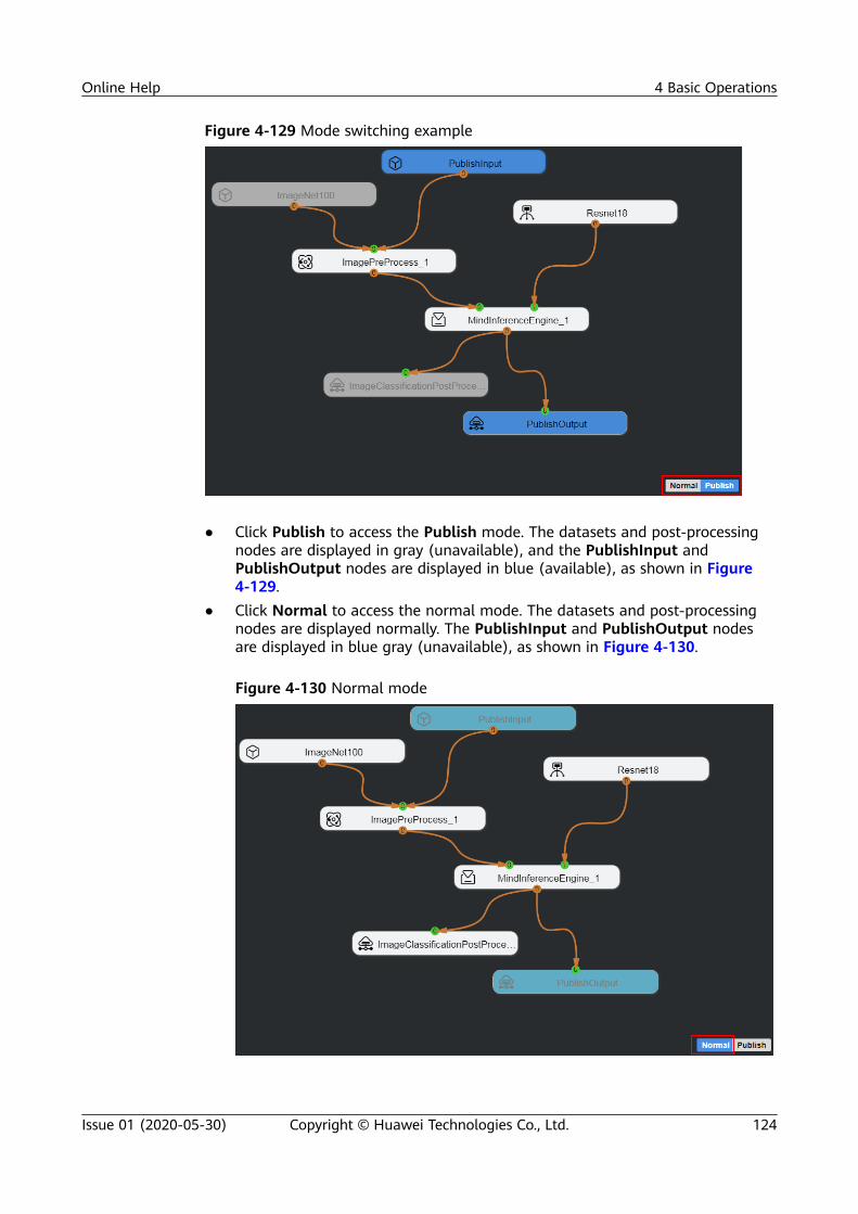
Figure 4-129 Mode switching example
● Click Publish to access the Publish mode. The datasets and post-processingnodes are displayed in gray (unavailable), and the PublishInput andPublishOutput nodes are displayed in blue (available), as shown in Figure4-129.
● Click Normal to access the normal mode. The datasets and post-processingnodes are displayed normally. The PublishInput and PublishOutput nodesare displayed in blue gray (unavailable), as shown in Figure 4-130.
Figure 4-130 Normal mode
Online Help 4 Basic Operations
Issue 01 (2020-05-30) Copyright © Huawei Technologies Co., Ltd. 124

4.6.2.3 Node Placement and ConnectionThis topic uses a complete process orchestration canvas as an example, as shownin Figure 4-131. For details about basic node operations, see 4.3.3 Basic NodeOperations.
Figure 4-131 Canvas without Publish nodes
Click Publish under the canvas in Figure 4-131 or drag the PublishInput orPublishOutput node under Publish on the Tool tab page to the canvas.
Figure 4-132 Publish node settings
Table 4-17 describes the parameters.
Online Help 4 Basic Operations
Issue 01 (2020-05-30) Copyright © Huawei Technologies Co., Ltd. 125

Table 4-17 Parameter description
Parameter Description
Publish Name Name of a published package. The name must startwith a letter and consists at most 30 characters andsupport letters (a-z, A-Z), digits (0–9), and underscores(_). The default value is the project name.
Publish Languages The value can be C++ or Python (default).
● To add a node by clicking Publish, perform the following steps:After you click Publish and set the parameters shown in Table 4-17, thePublishInput and PublishOutput nodes are added to the canvas. ThePublishInput node is connected in the same way as the datasets and thePublishOutput node is connected in the same way as the post-processingnode. In addition, the Normal and Publish buttons shown in the lower rightcorner of the canvas, and the dataset and post-processing node in the canvasare displayed in gray, as shown in Figure 4-133.
Figure 4-133 Clicking Publish
If you add a node in this mode, the PublishInput and PublishOutput nodes are addedto the canvas regardless of whether the canvas has nodes.
The folders named after the PublishInput and PublishOutput nodes areautomatically displayed in the project directory, as shown in Figure 4-134.Table 4-18 describes the files in the folders.
Online Help 4 Basic Operations
Issue 01 (2020-05-30) Copyright © Huawei Technologies Co., Ltd. 126

Figure 4-134 Project directory
Table 4-18 File description
File Description
PublishInput.cpp Template code, which is used to replacethe dataset on the orchestration network
PublishInput.h Template code header file
PublishOutput.cpp Template code, which is used to replacethe post-processing node on theorchestration network
PublishOutput.h Template code header file
● To add a node by dragging, perform the following steps:
Drag PublishInput or PublishOutput nodes under Publish on the Tool tabpage to the canvas and set the parameters shown in Figure 4-132. Thecorresponding nodes are displayed in the canvas, and the Normal andPublish buttons for mode switching are displayed in the lower right corner ofthe canvas. The dataset and the post-processing node in the canvas aredisplayed in gray (unavailable). In this mode, only one node can be draggedat a time, and the added nodes are not automatically connected, as shown inFigure 4-135.
Online Help 4 Basic Operations
Issue 01 (2020-05-30) Copyright © Huawei Technologies Co., Ltd. 127

Figure 4-135 Dragging a node
Drag another node to the canvas in the same way. In this case, you do notneed to set the parameters described in Figure 4-132. The folders namedPublishInput and PublishOutput are displayed in the project directory, asshown in Figure 4-134.
4.6.2.4 Packaging and PublishingFor details, see Engine Orchestration in Publish Mode > Packaging andPublishing in Ascend 310 Mind Studio Quick Start.
4.7 System Configuration Management
4.7.1 Tool SettingsYou can set the Mind Studio themed GUI and view plug-ins in the Setting... dialogbox .
IDE Settings● Editor settings
Choose IDE > Editor and set the display attributes of the Mind Studio, asshown in Figure 4-136.
Online Help 4 Basic Operations
Issue 01 (2020-05-30) Copyright © Huawei Technologies Co., Ltd. 128

Figure 4-136 Editor settings
For details about the parameters, see Table 4-19.
Table 4-19 Parameters of Editor settings
Category
Parameter Description
Fonts Font Size Sets the font size of the editor.
Font Family Sets the font style of the editor.
Keys Key Bindings Sets the editor style, Vi editing environment orEmacs editing environment.
Tabs Tab Size Sets the space width of the Tab key.
Edit Enable Autosave Enables code auto-saving.
Typing SmartIndentation
Enables smart indenting.
Typing-Autopair Enables symbol auto-pairing.
Autopair[Square]Brackets
Closes square brackets automatically.
Autopair"Quotations"
Closes quotation marks automatically.
Online Help 4 Basic Operations
Issue 01 (2020-05-30) Copyright © Huawei Technologies Co., Ltd. 129

Category
Parameter Description
Whitespaces
ShowWhitespaceCharacters
Shows whitespace characters.
Rulers Show LineNumber Ruler
Shows the line number ruler.
Show FoldingRuler
Shows the folding ruler.
Show OverwriteRuler
Shows the overwrite ruler.
Show ZoomRuler
Shows the zoom ruler.
– Setting the font size and style of the editor
i. In the main menu, choose File > Setting.... The Setting dialog box isdisplayed.
ii. Choose IDE > Editor from the navigation pane.iii. In the Fonts area on the right, choose a value from the Font Size
drop-down list box and choose a value from the Font Family drop-down list box.
iv. Click Save as shown in Figure 4-137. The font size and font style ofthe editor before and after the settings are shown in Figure 4-138and Figure 4-139.
Online Help 4 Basic Operations
Issue 01 (2020-05-30) Copyright © Huawei Technologies Co., Ltd. 130

Figure 4-137 Saving the font size and style settings
Figure 4-138 Default font size and style
Figure 4-139 Modified font size and style
Plug-ins DisplayChoose Plug-Ins > List from the navigation pane. The plug-in information aboutMind Studio is displayed on the right, as shown in Figure 4-140. Table 4-20describes the functions of some of the plug-ins.
Online Help 4 Basic Operations
Issue 01 (2020-05-30) Copyright © Huawei Technologies Co., Ltd. 131

Figure 4-140 Plug-in list
Table 4-20 Plug-in description
Parameter Description
BBoxExtension
Black box plug-in
Git Git plug-in
HelpExtension
Help plug-in
NvconfigExtension
NvConfig plug-in
SD MakingExtension
SD card making plug-in
SSH SSH plug-in
BuilderExtension
Compilation plug-in
CCE-GDB CCE-GDB debugging plug-in
CompareTool Extension
Tool comparison plug-in
ConvertmodelDebugger
Model conversion debugging plug-in
Online Help 4 Basic Operations
Issue 01 (2020-05-30) Copyright © Huawei Technologies Co., Ltd. 132

Parameter Description
Convertmodel
Model conversion plug-in
Cpp Cpp plug-in
C# C# plug-in
OfflineModel
Offline model plug-in
DvpptuningExtension
DVPP tuning plug-in
Logtool Log tool
RunExtension
Execution plug-in
PythonExtension
Python plug-in
TVM TVM plug-in
UpdatePackage
Upgrade plug-in
4.7.2 Assistant ToolThis chapter describes the functions and instructions of the Assistant tool.
4.7.2.1 OverviewThe Assistant of Mind Studio can be used to quickly query shortcut keys bound toMind Studio.
Figure 4-141 shows the Assistant page.
Figure 4-141 Assistant page
4.7.2.2 Querying a Shortcut Key
Step 1 Choose Assistant > Key Bindings on the toolbar. A dialog box is displayed, asshown in Figure 4-142.
Online Help 4 Basic Operations
Issue 01 (2020-05-30) Copyright © Huawei Technologies Co., Ltd. 133

Figure 4-142 Key Bindings dialog box
You can query the shortcut keys supported in the IDE and Editor.
● IDE: Contains the shortcut keys used in Mind Studio.● Editor: Contains the shortcut keys used for editing a document.
Click IDE or Editor to expand shortcut keys. Figure 4-143 shows the shortcut keyssupported in the IDE.
Online Help 4 Basic Operations
Issue 01 (2020-05-30) Copyright © Huawei Technologies Co., Ltd. 134

Figure 4-143 Shortcut keys supported in the IDE
Step 2 Enter keywords in the search text box to search for a shortcut key, as shown inFigure 4-144.
Online Help 4 Basic Operations
Issue 01 (2020-05-30) Copyright © Huawei Technologies Co., Ltd. 135

Figure 4-144 Searching for a shortcut key
----End
4.8 Change HistoryRelease Date Description
2020-05-30 This issue is the first official release.
Online Help 4 Basic Operations
Issue 01 (2020-05-30) Copyright © Huawei Technologies Co., Ltd. 136

5 Building the First AI Application
5.1 Workflow5.2 Engine Orchestration for the Classification Network5.3 Engine Orchestration for the Detection Network5.4 (Extended) Engine Orchestration Without Preprocessing5.5 (Extended) Multi-Network Engine Orchestration in Serial5.6 Engine Orchestration in Publish Mode5.7 Engine Orchestration Within the Open-Source Caffe Framework5.8 Appendix
5.1 WorkflowThe engine orchestration function of Mind Studio provides the AI engine-basedvisualized drag-and-drop programming and automatic generation of algorithmiccode, greatly reducing the difficulty for developers.
Service developers can orchestrate and run service processes by dragging graphicalservice nodes, connecting service nodes, and editing service node attributes toachieve "zero" programming of service process orchestration.
Figure 5-1 shows the service orchestration process on Mind Studio.
Figure 5-1 Service orchestration process
Online Help 5 Building the First AI Application
Issue 01 (2020-05-30) Copyright © Huawei Technologies Co., Ltd. 137

Table 5-1 describes the orchestration process.
Table 5-1 Process description
Process Description
Creating a Mindproject
If Target is set to ASIC or Atlas DK, see 5.2 EngineOrchestration for the Classification Network–5.5(Extended) Multi-Network Engine Orchestration inSerial .
If Target is set to Local, see 5.7 Engine OrchestrationWithin the Open-Source Caffe Framework.
Orchestratingengines
If the selected model file is a classification network model,see 5.2 Engine Orchestration for the ClassificationNetwork.
If the selected model file is a detection network model,see 5.3 Engine Orchestration for the DetectionNetwork.
If the engine orchestration does not contain the pre-processing node, see 5.4 (Extended) EngineOrchestration Without Preprocessing.
If multiple network models such as classification anddetection network models are selected, see 5.5(Extended) Multi-Network Engine Orchestration inSerial .
If you want to package a project and provide it to externalsystems using interfaces after the engine orchestrationand project running are complete, see 5.6 EngineOrchestration in Publish Mode.
Compiling a project The corresponding source code and execution script aregenerated.
Running a project The script output after compilation is executed.
End -
Mind Studio supports drag-and-drop programming, which reduces the difficulty fordeveloping AI engines. You can drag and drop nodes in a visualized manner toautomatically generate inference code, which is quite simple. The automatically generatedcode is the sample code in a typical application scenario and is for reference only. You mustidentify, modify, and optimize the code based on the actual application scenario.
5.2 Engine Orchestration for the Classification Network
Online Help 5 Building the First AI Application
Issue 01 (2020-05-30) Copyright © Huawei Technologies Co., Ltd. 138

5.2.1 Creating a Mind ProjectStep 1 In the main menu, choose File > New > New Project. The New Project dialog
box is displayed.
Step 2 In the New Project dialog box, choose Mind Engine Project > Mind Project. Theconfiguration window is displayed, as shown in Figure 5-2.
Figure 5-2 Creating a Mind engine project
Step 3 Configure the project by referring to Table 5-2.
Table 5-2 Parameter description
Parameter Description
Name Set the project name. Set this parameter as required.The name must be a character string without spaces. A space isautomatically filled with a hyphen (-).
Mind Type Select a project type from the drop-down list box.● DEFAULT: A canvas is generated as the project is created. You
can orchestrate the project by dragging.● CUSTOM: A custom project is created without generating a
canvas.
Online Help 5 Building the First AI Application
Issue 01 (2020-05-30) Copyright © Huawei Technologies Co., Ltd. 139

Parameter Description
Target Select a running environment from the drop-down list box.● Local: simulation environment, which is used for the Caffe
inference engine.● ASIC: EVB or PCIe card connected● Atlas DK: developer board connectedNOTE
If a local simulation project is created, model components under CaffeModels in Model must be used. For details about how to add a Caffemodel component, see 5.2.4 "Adding a Caffe Model Component" inAscend 310 Mind Studio Basic Operations. The pre-processing nodemust be ImagePreProcessPillow and the inference engine must beCaffeInferenceEngine. For details, see 5.7 Engine OrchestrationWithin the Open-Source Caffe Framework.
Source Code Select a code source from the drop-down list box.● Empty: The project is not imported externally.● Local(Web Client): The source file is imported from the
local Windows PC. The text box for uploading the source filesdisplayed.
● Local(Web Server): The source file is imported from thebackend server. The text box for entering the code path ofthe Mind Studio server is displayed.
In this example, set Mind Type to DEFAULT, Target to Atlas DK (developerboard), and Source Code to Empty.
Step 4 Click Create to create a Mind project. A .mind file is automatically generated as aDEFAULT Mind project is created. The name of the mind file name is the samename as the project name, as shown in Figure 5-3. The file cannot be copied,deleted, or renamed.
Figure 5-3 Creating a demo project
----End
5.2.2 Engine OrchestrationYou can double-click the .mind file (for example, Demo.mind) to open the engineorchestration window, as shown in Figure 5-4.
Online Help 5 Building the First AI Application
Issue 01 (2020-05-30) Copyright © Huawei Technologies Co., Ltd. 140

Figure 5-4 Engine orchestration window
In the following figure, you can place, delete, copy, set, save, and add a node. Fordetails, see "Basic Node Operations" in Ascend 310 Mind Studio Basic Operations.
Figure 5-5 shows an example of the ResNet-18 network.
Figure 5-5 ResNet-18 network example
The ResNet-18 network consists of the following nodes: a dataset, a model, a datapre-processing node, an execution engine, and an image post-processing node.
Procedure
Step 1 Add a model.
In this example, Model > Built-in Models > Resnet18 in Mind Studio is used.
To use your own model, choose [+] on the right of Model > My Models. In theConvert Model dialog box that is displayed, import the model file, that is, theweight file, configure the parameters, and convert the custom model into a modelsupported by the Huawei NPU.
For details about model conversion parameters, see "Adding a Custom ModelComponent" in Ascend 310 Mind Studio Basic Operations.
Step 2 Add a dataset node.
In this example, Datasets > BuiltIn Datasets > ImageNet100 in Mind Studio isused.
Online Help 5 Building the First AI Application
Issue 01 (2020-05-30) Copyright © Huawei Technologies Co., Ltd. 141

To use your own dataset, select [+] on the right of Datasets > My Datasets. Inthe displayed Import Dataset dialog box that is displayed, set Dataset Name,Data Type, and Data Source, and import the custom dataset.
For details about how to add dataset parameters, see "Importing a Dataset" inAscend 310 Mind Studio Basic Operations.
Step 3 Place the required nodes in their positions.1. On the Tool tab in the right pane, click Datasets to expand the dataset list
and expand its subitem My Datasets.2. Select the ImageNet control, hold down the left mouse button on the control,
drag it to the drawing area on the left, and release the left mouse button, asshown in Figure 5-6.
Figure 5-6 Placing a node
3. After the ImageNet node is placed, repeat Step 3.1 and Step 3.2 to place thefollowing four nodes:
● Resnet18 node under Model > Built-in Models● ImagePreProcess node under Preprocess● MindInferenceEngine node under Deep-Learning Execution Engine● ImageClassificationPostProcess node under Postprocess
After all nodes are configured, the final node placement result is displayed, asshown in Figure 5-7.
Figure 5-7 Node placement example
Online Help 5 Building the First AI Application
Issue 01 (2020-05-30) Copyright © Huawei Technologies Co., Ltd. 142

● When Target is set to ASIC or Atlas DK, select the ImagePreProcess node underPreprocess.
● When Target is set to Local, select the ImagePreProcessPillow node under Preprocess.● The CaffeInferenceEngine and MindInterfaceEngine nodes under Deep-Learning
Execution Engine are similar. They can also be used for the inference of theclassification network and detection network. However, CaffeInferenceEngine can onlyrun in a local simulation environment.
Step 4 Configure the node properties.
To meet the requirements of the ResNet-18 network, you need to set theproperties of the ImagePreProcess node.
1. Click ImagePreProcess.2. Enable the Resize function on the property tab on the right.3. Set resize_width and resize_height to 224 (enabled by default, and the
width and height are 224 x 224). The value of Resize must meet the modelinput requirements. The model size can be obtained from input_param in theprototxt file. For the ResNet18 model, the input data format must be 224 x224, as shown in Figure 5-8.
Figure 5-8 Modifying node properties
4. Check whether the value of OutputName in the post-processing nodeproperties is the same as the name of the operator at the last layer of themodel.
If the value of OutputName in the post-processing node properties is different fromthe name of the operator at the last layer of the model, the error message the outputnode name doesn't exist is displayed in the log during engine orchestration.
a. Check the value of OutputName in the post-processing node properties:Click the post-processing node and view the value of OutputName onthe Property tab page, as shown in Figure 5-9.
Online Help 5 Building the First AI Application
Issue 01 (2020-05-30) Copyright © Huawei Technologies Co., Ltd. 143

Figure 5-9 Setting the OutputName parameter
b. View the name of the operator at the last layer of the model:
i. Right-click a model and choose View Model from the shortcutmenu.
ii. On the window that is displayed, find the node at the bottom.iii. Click the last node. In the Op Info area, view the value of src _name,
which is the operator name. See Figure 5-10.
Figure 5-10 Name of the operator at the last layer
c. As shown in Step 4.4.a and Step 4.4.b, the value of the OutputNameparameter in the post-processing node properties is different from that ofsrc_name at the last layer of the model. In this case, change the value ofOutputName, as shown in Figure 5-11.
Figure 5-11 Modified OutputName parameter value
Online Help 5 Building the First AI Application
Issue 01 (2020-05-30) Copyright © Huawei Technologies Co., Ltd. 144

● In a simulation environment, the pre-processing node is ImagePreProcessPillow.- The configuration of Resize must be the consistent with that of ImagePreProcess.- Mean Value also needs to be set for this node (Subtraction average value/Averagevalue of channel n):
● The B, G, and R values of the inception_v4, xcecption, and inception_v3 models are all128. Retain the default values of mean_of_B, mean_of_G, and mean_of_R for othermodels. The default values are 104, 117, and 123, respectively.- Enable Scale for the densenet, moblienet, moblienet_v2, inception_v4, xcecption, andinception_v3 models. The value is the reciprocal of Multiplying Factor (MultiplyingFactor = Multiplying factor/Standard deviation of channel n or Multiplying Factor =Reciprocal of (Max – Min). Keep Scale disabled for other network models.
Step 5 Establish connections between nodes.
After the required nodes are placed and the properties are set, set up thecorresponding connections.
An orange round endpoint is an output port, from which a connection line can beled out. A green endpoint is an input port and can be used to place a connectionline. Figure 5-12 shows the final connections between the nodes.
Figure 5-12 Setting up connections between nodes
NO TICE
Pay attention to the following points when setting up the connections:● The Preprocess node must be connected to input port 0 of the Deep Learning
Execution Engine node.● The Model node must be connected to input port 1 of the Deep-Learning
Execution Engine node.
Online Help 5 Building the First AI Application
Issue 01 (2020-05-30) Copyright © Huawei Technologies Co., Ltd. 145

Step 6 Click Save at the bottom of the canvas to save the orchestration process.
----End
5.2.3 Compiling and RunningMind Engine supports one-click compilation and execution in the device orsimulation environment. Different operations are performed during executionaccording to how a project is configured. The following uses the Atlas 200 DKdeveloper board as an example.
Compiling
Step 1 After editing the network structure, click Generate in the lower left corner togenerate the source code and execution script, as shown in Figure 5-13.
Figure 5-13 Compiling a project
Step 2 After the project is compiled, the corresponding source code and executable filesare automatically generated, as shown in Figure 5-14.
Online Help 5 Building the First AI Application
Issue 01 (2020-05-30) Copyright © Huawei Technologies Co., Ltd. 146

Figure 5-14 Files generated after compilation
Step 3 Parse the graph.config file.
The engine parameters and the connection between the engines are configured inthe graph file.
● As shown in Figure 5-15, 881 is the ID of ImagePreProcess, and 224 is thevalue of resize_width and resize_height.
Online Help 5 Building the First AI Application
Issue 01 (2020-05-30) Copyright © Huawei Technologies Co., Ltd. 147

Figure 5-15 Example of the configuration information in the graph file
● As shown in Figure 5-16, the connection information of the engines isconfigured in the graph file. The output data of engine 881 is used as theinput data of engine 150.
Online Help 5 Building the First AI Application
Issue 01 (2020-05-30) Copyright © Huawei Technologies Co., Ltd. 148

Figure 5-16 Connection information in the graph file
----End
Running
When the Target configuration item of the project is set to ASIC or Atlas DK, the RunConfiguration dialog box, as shown in Figure 5-17, will be displayed after Run is clicked.You need to configure the host IP address. In a simulation environment, the hardwareaddress does not need to be configured, and the running process is automatically started.During project running, model files, configuration files, link libraries, binary programs, andinput and output data will be automatically copied to the host side. To improve the runningperformance, Mind Studio does not automatically delete the data on the host side. If thesefiles are not needed, log in to the host and delete the obsolete folders in /home/HwHiAiUser/HIAI_DATANDMODELSET and /home/HwHiAiUser/HIAI_PROJECTS.
Step 1 Click Run at the bottom of the canvas and configure the IP address of thehardware platform, as shown in Figure 5-17.
Figure 5-17 Running configuration
Step 2 After the configuration is complete, click Run to start the Mind Engineorchestration process. You can view the corresponding running output on the dev-machine tab page.
Online Help 5 Building the First AI Application
Issue 01 (2020-05-30) Copyright © Huawei Technologies Co., Ltd. 149

Figure 5-18 Saving the device information
Figure 5-19 Running output
----End
5.2.4 Viewing the Running ResultAfter running is complete, a result folder named after the timestamp is generatedin the out folder in the root directory of the project. In this case, you can right-click the Postprocess node and choose a result from the shortcut menu to viewthe result.
Online Help 5 Building the First AI Application
Issue 01 (2020-05-30) Copyright © Huawei Technologies Co., Ltd. 150

Figure 5-20 Shortcut menu
There are three types of results: Image Result, Statistical Result, and ProfilingResult.
Check whether the input dataset contains the ground truth file (calibrated truthdata) and label file (label dictionary file), which affect the image result andstatistical result.
The following describes how to select a label dictionary when a dataset isimported:
The label dictionary file is imported during data import. Set Data Type toImageNet, Ground Truth File to the calibrated truth data, and Label File to thelabel dictionary file, as shown in Figure 5-21.
For details about the tag dictionary example, see Tag Dictionary.zip in theresource folder.
Figure 5-21 Configurations for importing a label dictionary file
Different options lead to different results, as described in Table 5-3.
Online Help 5 Building the First AI Application
Issue 01 (2020-05-30) Copyright © Huawei Technologies Co., Ltd. 151

Table 5-3 Results of different options
InputDataImages
GroundTruth File
LabelFile
Result Availability
Import Selected Selected
Both Image Result and Statistical Resultcan be displayed.In Image Result, the image category afterinference and the category label aredisplayed.
Import Selected - Both Image Result and Statistical Resultcan be displayed.In Image Result, only the image categoryNo. after inference is displayed while thecategory labels are not displayed.
Import - Selected
Only Image Result is displayed.In Image Result, the image category afterinference and the category label aredisplayed.
Import - - Only Image Result is displayed.In Image Result, only the image categoryNo. after inference is displayed while thecategory labels are not displayed.
Therefore, the statistical result availability depends on the ground truth file whilethe image result availability depends on the label file. The details are described asfollows:
Image ResultImage Result displays the prediction result of image inference. The category andprediction probability are shown on the upper left corner of each result image.● If a label dictionary file that matches the model is provided along with the
imported dataset, the label text is also displayed, as shown in Figure 5-22.
Online Help 5 Building the First AI Application
Issue 01 (2020-05-30) Copyright © Huawei Technologies Co., Ltd. 152

Figure 5-22 Image result example 1 for the classification network
The label on each image represents a category and the probability that the imagebelongs to the category. Labels may share similar meanings. Therefore, one imagemay have multiple category labels.
● If the label dictionary file is not imported or the label dictionary file does notmatch the model, only the label ID is displayed, as shown in Figure 5-23.
Online Help 5 Building the First AI Application
Issue 01 (2020-05-30) Copyright © Huawei Technologies Co., Ltd. 153

Figure 5-23 Image result example 2 for the classification network
● No.*** (for example, No.692) indicates the predicted category No., and thepercentage (for example, 22.05%) indicates the probability that the image belongsto the category.
● The label numbers in the post-processing result of the classification network startfrom "0". For example, for 1000 types of datasets, when the model is ResNet18and the post-processing node of the corresponding classification network is used,the label numbers of the images in the inference result are 0 to 999.
Statistical ResultIf a calibrated ground truth file is imported along with the dataset, StatisticalResult is available.
The statistical result is displayed as a table, listing the number of inferred images,the number of categories (the default number of categories for ImageNet is1000), and the top n hit accuracy, as shown in Figure 5-24.
Figure 5-24 Statistical result example
Online Help 5 Building the First AI Application
Issue 01 (2020-05-30) Copyright © Huawei Technologies Co., Ltd. 154

Table 5-4 Statistical result description
Parameter Description
Number of images Total number of input images
Number of classes Total number of categories
Top1 accuracy Prediction accuracy of the top 1 category
Top2 accuracy Prediction accuracy of the top 2 categories
Top3 accuracy Prediction accuracy of the top 3 categories
Top4 accuracy Prediction accuracy of the top 4 categories
Top5 accuracy Prediction accuracy of the top 5 categories
Profiling Result
The profiling result is displayed only after the compilation in a simulation environment. Fordetails about profiling in the Atlas DK or ASIC environment, see "Profiling" in Ascend 310Mind Studio Auxiliary Tools.
The result is the profiling data during the network running. It contains thefollowing contents.
Figure 5-25 Profiling result
Online Help 5 Building the First AI Application
Issue 01 (2020-05-30) Copyright © Huawei Technologies Co., Ltd. 155

The histogram displays the running time and memory usage of each layer of themodel. Table 5-5 describes the content of the table in the histogram.
Table 5-5 Table in the histogram
resNet Level Name of the Model
input Size of the memory occupied by the input data
output Size of the memory occupied by the output data
weight Weight
workspace Size of the temporary memory used during operator computation
total Total memory size
Time Running time
Mac Ratio MAC usage
Click View Report to download the output data of the corresponding layer, asshown in Figure 5-26.
Figure 5-26 View Report
5.3 Engine Orchestration for the Detection Network
5.3.1 Creating a Mind projectFor details, see 5.2.1 Creating a Mind Project.
Online Help 5 Building the First AI Application
Issue 01 (2020-05-30) Copyright © Huawei Technologies Co., Ltd. 156

5.3.2 Engine OrchestrationYou can double-click the .mind file (for example, Demo.mind) to open the engineorchestration window, as shown in Figure 5-27.
Figure 5-27 Engine orchestration window
In the following figure, you can place, delete, copy, set, save, and add a node. Fordetails, see "Basic Node Operations" in Ascend 310 Mind Studio Basic Operations.
Figure 5-28 shows an example of the Faster R-CNN network.
Figure 5-28 Faster R-CNN example
A Faster R-CNN network consists of at least the following nodes: one dataset(Pascal100), one model (Faster R-CNN), one data preprocessing(ImagePreProcess), one model image information (FastRCNNImageInfo), oneexecution engine (MindInferenceEngine), and one image post-processing node(FasterRCNNPostProcess).
Online Help 5 Building the First AI Application
Issue 01 (2020-05-30) Copyright © Huawei Technologies Co., Ltd. 157

Figure 5-29 shows an example of the SSD network.
Figure 5-29 SSD network example
An SSD network consists of at least the following nodes: one dataset (Pascal100),one model (SSD), one data preprocessing (ImagePreProcess), one executionengine (MindInferenceEngine), and one image post-processing node(SSDPostProcess).
PrerequisitesIf the Faster R-CNN or SSD network is used to orchestrate the process, and thepost-processing node is FasterRCNNPostProcess or SSDPostProcess, add thefollowing operator to the last layer of the model file before importing the Caffemodel file (for example, faster-rcnn_resent18.prototxt). Otherwise, engineorchestration fails. If the model file contains this operator already, check theinformation.
Add the following content at the last layer of the Faster R-CNN model file:layer { name: "detection_out" #Operator name type: "FSRDetectionOutput" # Operator type bottom: "cls_prob" # Input score bottom: "bbox_pred" # Predicted correction coordinate bottom: "rois" # ROI generated on the original feature map top: "out_box_num" # Number of active ouput boxes top: "detection_out" # Coordinate of an active output box detection_output_param { num_classes: 21 # Number of classfications (including the background) nms_threshold: 0.3 # Non-maximum suppression (NMS) threshold confidence_threshold: 0.8 # Filter box threshold } }
Add the following content at the last layer of the SSD model file:layer { name: "detection_out" # Operator name
Online Help 5 Building the First AI Application
Issue 01 (2020-05-30) Copyright © Huawei Technologies Co., Ltd. 158

type: "SSDDetectionOutput" bottom: "mbox_loc" # mbox_loc coordinate input bottom: "mbox_conf_flatten" # Classification score input bottom: "mbox_priorbox" # Prior box generated on the original feature map top: "detection_out" # Operator ouput name include { phase: TEST } detection_output_param { num_classes: 21 # Number of classifications (including background) share_location: true # Box shared by all classifications background_label_id: 0 # Background classifiction ID nms_param { nms_threshold: 0.45 # NMS threshold top_k: 400 # Number of boxes after NMS } save_output_param {label_map_file: "$HOME/labelmap_voc.prototxt" # Save the labelmap_voc.prototxt file in any path on the Mind Studio server as the Mind Studio installation user, for example, $HOME. For the file content, see Appendix >labelmap_voc File Content. } code_type: CENTER_SIZE # Coordinate correction mode keep_top_k: 200 # Number of final output boxes confidence_threshold: 0.3 # Filter box threshold } }
The following uses the Faster R-CNN model file as an example:
Click on the right of My Models to add the custom Faster R-CNN modelcomponent. After importing the model, drag the model to the canvas, right-clickthe model, and choose View Model from the shortcut menu, as shown in Figure5-30.
Figure 5-30 Choosing View Model from the shortcut menu
The network structure shown in Figure 5-31 is displayed. The last layer input ofthe network structure of the original model consists of a prediction layer(bbox_pred) and a classification prediction layer (cls_prob). If the detection_outoperator is not added, post-processing cannot be performed directly. WhenFasterRCNNPostProcess is added for engine orchestration with post-processing,the execution fails.
Online Help 5 Building the First AI Application
Issue 01 (2020-05-30) Copyright © Huawei Technologies Co., Ltd. 159

Figure 5-31 Network structure of the original model
After the detection_out operator is added to the last layer of the original modelnetwork structure, as shown in Figure 5-32, engine orchestration with post-processing (FasterRCNNPostProcess) can be directly performed.
Figure 5-32 Model network structure with the detection_out operator
The attachment faster-rcnn_prototxt.zip in the resource folder contains a modelfile without the detection_out operator and a model file with the detection_outoperator. They are for reference only.
ProcedureFor details, see 3.1.2 "Engine Orchestration."
Step 1 For details, see Step 1.
Step 2 For details, see Step 2.
Step 3 Place the required nodes in their positions. For details about how to place a node,see Step 3.
Online Help 5 Building the First AI Application
Issue 01 (2020-05-30) Copyright © Huawei Technologies Co., Ltd. 160

Table 5-6 and Table 5-7 describe the nodes required by the Faster R-CNNnetwork and SSD network, respectively.
Table 5-6 Nodes required by the Faster R-CNN network
Input Source Remarks
Dataset Datasets > Built-in Datasets> Pascal100
-
Model Model > My Models >FasterRCNN
The Faster R-CNN model is importedby users. For details about how toimport the model, see "Adding aCustom Model Component" inAscend 310 Mind Studio BasicOperations.
Data pre-processing
Preprocess >ImagePreProcess
For details about how to set thevalues of resize_width andresize_height in the node properties,see Step 4.NOTE
When Target is set to ASIC or Atlas DK,select the ImagePreProcess node underPreprocess.
Modelimageinformation
Customize >FastRCNNImageInfo
-
Executionengine
Deep-Learning ExecutionEngine > MindInferenceEn-gine
-
Online Help 5 Building the First AI Application
Issue 01 (2020-05-30) Copyright © Huawei Technologies Co., Ltd. 161

Input Source Remarks
Imagepost-processingnode
Postprocess >FasterRCNNPostProcess
Check whether the value ofOutputName in the post-processingnode properties is the same as thename of the operator at the lastlayer of the model. If they aredifferent, the error message theoutput node name doesn't exist isdisplayed during engineorchestration. For details, see Step4.4.View the name of the operator atthe last layer of the model:1. Right-click a model and choose
View Model from the shortcutmenu.
2. On the window that is displayed,find the node at the bottom.
3. Click the last node. In the Op Infoarea, view the value of src _name,which is the operator name. SeeFigure 5-33.
Table 5-7 Nodes required by the SSD network
Input Source Remarks
Dataset Datasets > Built-in Datasets> Pascal100
-
Model Model > My Models > SSD The SSD model is imported by users.For details about how to import themodel, see "Adding a Custom ModelComponent" in Ascend 310 MindStudio Basic Operations.
Data pre-processing
Preprocess >ImagePreProcess
For details about how to set thevalues of resize_width andresize_height in the node properties,see Step 4.NOTE
When Target is set to ASIC or Atlas DK,select the ImagePreProcess node underPreprocess.
Executionengine
Deep-Learning ExecutionEngine > MindInferenceEn-gine
-
Online Help 5 Building the First AI Application
Issue 01 (2020-05-30) Copyright © Huawei Technologies Co., Ltd. 162

Input Source Remarks
Imagepost-processingnode
PostProcess >SSDPostProcess
Check whether the value ofOutputName in the post-processingnode properties is the same as thename of the operator at the lastlayer of the model. If they aredifferent, the error message theoutput node name doesn't exist isdisplayed during engineorchestration. For details, see Step4.4.View the name of the operator atthe last layer of the model:1. Right-click a model and choose
View Model from the shortcutmenu.
2. On the window that is displayed,find the node at the bottom.
3. Click the last node. In the Op Infoarea, view the value of src_name, which is the operatorname. See Figure 5-34.
Figure 5-33 Name of the operator at the last layer of Faster R-CNN
Online Help 5 Building the First AI Application
Issue 01 (2020-05-30) Copyright © Huawei Technologies Co., Ltd. 163

Figure 5-34 Name of the operator at the last layer of SSD
Step 4 Set the Resize attribute of the pre-processing node.
The resize values of the pre-processing node must be the same as the modelinput. The model size can be obtained from input_param in the prototxt file, asshown in Figure 5-35.
Figure 5-35 Setting the Resize attribute
Step 5 Establish connections between nodes.
After the required nodes are placed and the properties are set, set up thecorresponding connections.
An orange round endpoint is an output port, from which a connection line can beled out. A green endpoint is an input port and can be used to place a connectionline.
Figure 5-36 shows the final connections between the Faster R-CNN nodes.
Online Help 5 Building the First AI Application
Issue 01 (2020-05-30) Copyright © Huawei Technologies Co., Ltd. 164

Figure 5-36 Connections between the Faster R-CNN nodes
Pay attention to the following points when setting up the connections:1. In the property settings of the Deep Learning Execution Engine node, set Input Count
to 3.2. The Preprocess node must be connected to input port 0 of the Deep Learning Execution
Engine node.3. The FasterRCNNImageInfo node must be connected to input port 2 of the Deep
Learning Execution Engine node.4. The Model node must be connected to input port 1 of the Deep Learning Execution
Engine node.
Figure 5-37 shows the final connections between the SSD nodes.
Figure 5-37 Connections between the SSD nodes
Online Help 5 Building the First AI Application
Issue 01 (2020-05-30) Copyright © Huawei Technologies Co., Ltd. 165

NO TICE
Pay attention to the following points when setting up the connections:
1. The Preprocess node must be connected to input port 0 of the Deep LearningExecution Engine node.
2. The Model node must be connected to input port 1 of the Deep LearningExecution Engine node.
Step 6 Click Save at the bottom of the canvas.
Save the orchestration process.
----End
5.3.3 Compiling and RunningFor details, see 5.2.3 Compiling and Running.
5.3.4 Viewing the Running ResultAfter running is complete, a result folder named after the timestamp is generatedin the out folder in the root directory of the project. In this case, you can right-click the Postprocess node and choose a result from the shortcut menu to viewthe result.
Figure 5-38 Shortcut menu
There are three types of results: Image Result, Statistical Result, and ProfilingResult.
Image Result
Image Result displays the inference prediction result. For the detection network,BBoxes and confidence values are displayed on the result images. See Figure 5-39.
Online Help 5 Building the First AI Application
Issue 01 (2020-05-30) Copyright © Huawei Technologies Co., Ltd. 166

Figure 5-39 Image result example 1 for the detection network
1. The label in the image represents the inferred category of the image and the confidencevalue of the inference.2. The rectangular frame in the image indicates the inferred location of the target object.
● If the label dictionary file is not imported or the label dictionary file does notmatch the model, only the label ID is displayed, as shown in Figure 5-40.
Figure 5-40 Image result example 2 for the detection network
Online Help 5 Building the First AI Application
Issue 01 (2020-05-30) Copyright © Huawei Technologies Co., Ltd. 167

● Label*** (for example, Label 1) indicates the predicted category No., and thepercentage (for example, 37.36%) indicates the probability that the image belongsto the category.
● The label numbers in the post-processing result of the detection network startfrom "0". For example, for 20 types of PASCAL datasets, when the model is FasterR-CNN and the post-processing node of the corresponding detection network isused, the label numbers of the images in the inference result are 0 to 19.
Statistical Result
The statistical result is displayed as a table, listing the number of inferred images,the number of categories (the default number of categories for Pascal is 20), andconfidence value of each category and the general prediction mAP value, asshown in Figure 5-41.
Figure 5-41 Statistical result example
To view the statistical result, the image data to be inferred must be contained in the labelfile. Otherwise, the following error message is displayed, as shown in Figure 5-42.
During statistics collection, the timeout set for the server to parse the inference results is30s. If too many images are selected from the dataset for inference, the server may fail toparse them within 30s. As a result, an error is reported, and the inference result cannot beviewed on the GUI.
Figure 5-42 Error message
Online Help 5 Building the First AI Application
Issue 01 (2020-05-30) Copyright © Huawei Technologies Co., Ltd. 168

Profiling Result
For details, see Profiling Result.
5.4 (Extended) Engine Orchestration WithoutPreprocessing
5.4.1 OverviewTo eliminate the pre-processing impact on the result, the Preprocess node can beomitted during engine orchestration, that is, engine orchestration without pre-processing.
Prerequisites
This topic is the extension of 5.1 Workflow.
Function Description
The ResNet-18 network is used as an example. Orchestration without pre-processing involves the following nodes:
A dataset, a model, an execution engine, and an image post-processing node, asshown in Figure 5-43.
Figure 5-43 Engine orchestration example without pre-processing
5.4.2 Engine Orchestration
Context● In this section, the engine refers to MindInferenceEngine.● The network model is ResNet-18. You can use the built-in ResNet-18 network
of the tool or import a custom model. For details about how to import a
Online Help 5 Building the First AI Application
Issue 01 (2020-05-30) Copyright © Huawei Technologies Co., Ltd. 169

custom model, see "Adding a Custom Model Component" in Ascend 310 MindStudio Basic Operations.
● The network structure is orchestrated without a pre-processing node.
ProcedureTable 5-8 describes the orchestration process and precautions.
Table 5-8 Engine orchestration without a pre-processing node
Procedure
Environment Configuration
Creating aMindproject
Set Target to ASIC or Atlas DK.
Editingthenetworkstructure
The following dataset formats are supported:● Raw float format: one of the BGR float formats. Select the raw
dataset for import. The model must be a user-defined networkmodel without the aipp file. That is, you need to set OptionalOptions and Input Image Process to Off when importing thenetwork model.
● Raw U8 format: one of the BGR U8 formats. Select the rawdataset for import. A user-defined network model, such as astatic AIPP model or a dynamic AIPP model, must be used.NOTE
If a dynamic AIPP model is used for datasets in the raw U8 and NV12formats, modify the code in MindInferenceEngine, as shown in Figure5-44.
● nv12 format: one of the YUV420 planar formats. Select theimage dataset for import.NOTE
The width and height of the nv12 dataset must be 256 and 224,respectively.
Compilingandrunning
For details, see 5.2.3 Compiling and Running.
Viewingtherunningresult
For details, see 5.2.4 Viewing the Running Result.
Online Help 5 Building the First AI Application
Issue 01 (2020-05-30) Copyright © Huawei Technologies Co., Ltd. 170

Figure 5-44 Modifying the code
Figure 5-45 shows an example of the orchestrated network structure.
Figure 5-45 Engine orchestration example without pre-processing in the EVBenvironment
5.5 (Extended) Multi-Network Engine Orchestration inSerial
5.5.1 OverviewProcess orchestration is a directional graph. The involved concepts are as follows:
● NodeVertex of the graph, such as 0, 1, 2, 3, 4, 5, 6, 7, and 8 in Figure 5-46
● BranchEdge of the graph, such as 0->1, 0->3, 0->5, 1->2, 1->4, 3->6, 5->8, and 8->7in Figure 5-46.
● RootVertex puts forth one or more branches. Each node of a tree can serve as aroot. As shown in Figure 5-46, node 0 can be the root.
● Leaf
Online Help 5 Building the First AI Application
Issue 01 (2020-05-30) Copyright © Huawei Technologies Co., Ltd. 171

After a root is selected in a tree, for example, node 0, a node that cannot putforth branches becomes a leaf. As shown in Figure 5-46, the root is node 0,and nodes 2, 4, 6, and 7 are leaves.
Figure 5-46 Graph example
PrerequisitesThis topic is the extension of 5.1 Workflow.
Function DescriptionIn previous sections, only one network is involved in the orchestration for imageprocessing. In actual applications, more than one network can be used. The keyelements in an image can be selected by using a detection network. Then, theselected elements can be fine processed by using a classification network oranother detection network.
● In the case of a single network, the end point of the network is the post-processing node.
● In the case of multiple networks, the output data of the post-processing nodeof the intermediate network serves as the input data of the downstreamnetwork.In the currently supported post-processing nodes, only the SSDPostProcessand FasterRCNNPostProcess nodes can be directly configured with outputports and output conditions, so that the two post-processing results of thedetection networks and the original dataset can be sent to the downstreamnetwork for further processing.
Currently, only detection networks SSDPostProcess and FasterRCNNPostProcess beconfigured with output ports and output conditions.
Figure 5-47 shows a simple multi-network connection in serial.
Online Help 5 Building the First AI Application
Issue 01 (2020-05-30) Copyright © Huawei Technologies Co., Ltd. 172

Figure 5-47 Multi-network engine orchestration
5.5.2 Engine Orchestration
PrerequisitesThe SSD or Faster R-CNN detection network models are ready and imported toMy Models.
For details about how to add a custom model component, see Ascend 310 Mind StudioBasic Operations.
ProcedureTable 5-9 describes the orchestration process and precautions.
Table 5-9 Engine orchestration in the multi-network connection scenario
Procedure
Environment Configuration
Creating aMindproject
Set Target to ASIC or Atlas DK.
Online Help 5 Building the First AI Application
Issue 01 (2020-05-30) Copyright © Huawei Technologies Co., Ltd. 173

Procedure
Environment Configuration
Editingthenetworkstructure
● Datasets: In the current example, this parameter is set to thebuilt-in Pascal dataset.NOTE
A raw dataset is not supported in the multi-network connection scenario.
● Model: The first network can only be the SSD or FasterRCNNdetection network model in My Models. This example uses theSSD detection network model.
● Pre-processing node: Only ImagePreProcess is supported.NOTE
Because the SSD network model is used, set resize_width andresize_height of the first network pre-processing node to 300.
● Inference engine: Only MindInferenceEngine is supported.● Post-processing node: The post-processing node of the first
network can only be SSDPostProcess or FasterRCNNPostPro-cess. For details, see 5.5.2.1 Setting the Post-ProcessingOutput of the Detection Network and 5.5.2.2 Connecting thePost-processing Node of a Detection Network with the Pre-Processing Node of the Following Network.
Compilingandrunning
Before compilation, verify the graph by referring to 5.5.2.3Verifying the Graph Before Compilation. If the verification issuccessful, follow 5.2.3 Compiling and Running.
Viewingtherunningresult
For details, see 5.2.4 Viewing the Running Result.NOTE
If no content is detected after the image passes through the first networkinference, that is, there is no detection box in the image, the image will notbe input to the second network. The inference result of the image cannot beviewed on the final post-processing node (that is, the number of imagesobtained through inference may be less than the number of images that areinitially input).
5.5.2.1 Setting the Post-Processing Output of the Detection NetworkAfter engine orchestration, you need to configure the output ports and outputconditions.
Setting the Number of Output PortsDrag the SSDPostProcess or FasterRCNNPostProcess node to the canvas, clickthe node in the canvas, and set Output Count to 1 (the value range is 0 to 15), asshown in Figure 5-48. If Output Count is greater than 0, a corresponding numberof output ports are displayed below the post-processing node, ready forconnection.
Online Help 5 Building the First AI Application
Issue 01 (2020-05-30) Copyright © Huawei Technologies Co., Ltd. 174

Figure 5-48 Setting Output Count for post-processing of the detection network
Setting the Output Conditions● If Output Count is greater than 0, expand the Advance drop-down list, the
Output Settings item is displayed, as shown in Figure 5-49.
Figure 5-49 Finding Output Settings
● Click next to Output Settings. A dialog box is displayed, as shown inFigure 5-50. Table 5-10 describes the GUI parameters.
Figure 5-50 Setting the output conditions
Online Help 5 Building the First AI Application
Issue 01 (2020-05-30) Copyright © Huawei Technologies Co., Ltd. 175

Table 5-10 Parameters for setting the output conditions
Parameter Description
Port Port ID. Because SSDPostProcess has only oneoutput port, the port ID in this example is 0.
Label Category label. The value is a number.In this example, set this parameter to 1.
Confidence Confidence level. The value range is [0, 100]. In thisexample, set this parameter to 80, indicating thatthe port sends only images whose label is 1 andwhose confidence level is greater than 80% to thenext node.
If no filter criterion is configured for a port, all network processing results are outputto the next port.
● You can set multiple filter criteria. They are displayed in the Output Settingsarea, as shown in Figure 5-51. The confidence level can be quickly modifiedhere.
Figure 5-51 Setting filter criteria
To delete a filter criterion, right-click Setting0 and choose delete from theshortcut menu, as shown in Figure 5-52.
Online Help 5 Building the First AI Application
Issue 01 (2020-05-30) Copyright © Huawei Technologies Co., Ltd. 176

Figure 5-52 Deleting a filter criterion
5.5.2.2 Connecting the Post-processing Node of a Detection Network withthe Pre-Processing Node of the Following Network
Drag a pre-processing node to the canvas, click the node and view its properties.Enable the Crop switch to add an input node. Then enable the From-Upperswitch. The number of input ports on the pre-processing node is changed from 1to 2. That is, the dataset connection port ID is 0 and the port ID for connecting thepost-processing output port is 1. See Figure 5-53.
Figure 5-53 Setting the pre-processing input
5.5.2.3 Verifying the Graph Before Compilation
Connect the nodes required for engine orchestration and click Generate. Thefollowing verification is performed on the engine orchestration graph:
● If the nodes in the graph are not connected, a message is displayed indicatingthat compilation fails due to an unconnected graph.
● If a graph has multiple inference engines, they all must run on either thedevice side or the host side.
Online Help 5 Building the First AI Application
Issue 01 (2020-05-30) Copyright © Huawei Technologies Co., Ltd. 177

For details about the service node to which the inference engine belongs, see "ServiceNode Overview" in Ascend 310 Mind Studio Basic Operations.
● If a node in the graph is not connected, compilation fails.● Leaf nodes must run on the host side (this verification is not required for
developer boards). Otherwise, compilation fails.● Currently, parallel networks are not supported.
5.6 Engine Orchestration in Publish Mode
5.6.1 OverviewThis chapter describes how to orchestrate an engine in publish mode andillustrates the differences between compilation in normal mode and compilationin publish mode.
5.6.2 Engine Orchestration
Prerequisites
You are familiar with the function described in 5.1 Workflow.
Procedure
Table 5-11 describes the orchestration process and precautions.
Table 5-11 Engine orchestration process
Orchestration
Environment Configuration
Creating aMindProject
● Mind Type: Only DEFAULT is supported.● Target: Only ASIC or Atlas DK is supported.
Editingthenetworkstructure
● Datasets: The JPG, PNG, BMP, BIN, and JPEG formats aresupported. In the current example, the built-in datasetImageNet100 is used.
● Model: You can use a built-in model or add a custom model. Inthe current example, the built-in model ResNet18 is used.NOTE
For details about how to add a custom model component, see Ascend310 Mind Studio Basic Operations.
● Pre-processing node: Only ImagePreProcess is supported.● Inference engine: Only MindInferenceEngine is supported.● Post-processing node: In the current example, ImageClassifica-
tionPostProcess is selected.
Online Help 5 Building the First AI Application
Issue 01 (2020-05-30) Copyright © Huawei Technologies Co., Ltd. 178

Orchestration
Environment Configuration
Compilingandrunning
For details, see 5.6.3 Compiling and Running.
Packagingandpublishing
For details, see 5.6.4 Packaging and Publishing.
Figure 5-54 shows an example of the orchestrated network structure.
Figure 5-54 Example of engine orchestration in publish mode
5.6.3 Compiling and Running
Compilation in Publish Mode
Step 1 Drag a node to the canvas and connect the node. For details, see "Basic NodeOperations" in Ascend 310 Mind Studio Basic Operations. Select the built-indataset ImageNet100 and the built-in model ResNet18. Set the pre-processingnode to ImagePreProcess, the inference engine to MindInferenceEngine, and thepost-processing node to ImageClassificationPostProcess.
Step 2 Generate the PublishInput and PublishOutput nodes. For details, see "ModeSwitching" in Ascend 310 Mind Studio Basic Operations.
Step 3 After editing the network structure, click Generate in the lower left corner togenerate the source code and execution script, as shown in Figure 5-55.
Online Help 5 Building the First AI Application
Issue 01 (2020-05-30) Copyright © Huawei Technologies Co., Ltd. 179

Figure 5-55 Compiling a project
Step 4 After the project compilation is complete, the Publish folder is generated in theproject root directory, as shown in Figure 5-56.
Figure 5-56 Directory generated after compilation
Table 5-12 describes the parameters.
Table 5-12 Compiled parameters in publish mode
Level-1Directory
Level-2Directory
Description
device Makefile Template code file on the device side, which isused to compile and generate the .so library onwhich the C++ or Python publishing interfacedepends
Online Help 5 Building the First AI Application
Issue 01 (2020-05-30) Copyright © Huawei Technologies Co., Ltd. 180

Level-1Directory
Level-2Directory
Description
host Makefile Template code file on the host side, which isused to compile and generate the .so library onwhich the C++ or Python publishing interfacedepends
cpp - Folder that is displayed only when PublishLanguages is set to C++ after the PublishInputand PublishOutput nodes are added to thecanvas
Makefile Used to compile and generate the .so library onwhich the C++ publishing interface depends
main.cpp Sample code
test_publish.cpp C++ publish interface file, which is named afterthe project
test_publish.h Header file for the C++publish interface file,which is named after the project
python - Folder that is displayed only when PublishLanguages is set to Python after thePublishInput and PublishOutput nodes areadded to the canvas
python_cpp Folder that stores the dependency files forPython to call C++
python_include Folder that stores the header files of thedependency files for Python to call C++
main.py Sample code
mindengine_test_publish.py
File for interaction between Python and C++
setup.py Python compilation file, which is used togenerate the .so library on which the file forinteraction between Python and C++ depends
tensor.py Data structure file
tensor_list.py Data structure file
test_publish.i Used to generate mindengine_test_publish.py(which is the file for interaction between Pythonand C++) and named after the project
build.sh - Used to call Makefile in the device and hostfolders to generate the required .so file
graph.config
- Configuration file of an engine
Online Help 5 Building the First AI Application
Issue 01 (2020-05-30) Copyright © Huawei Technologies Co., Ltd. 181

Step 5 Parse the graph.config file.
In the graph file, the engine parameters and engine connection information areconfigured. In publish mode, the dataset and post-processing node are unavailable(in gray). Therefore, the information about the two nodes is not written to thegraph.config file during compilation.
● As shown in Figure 5-57, 213 is the ID of the PublishInput node. The value ofso_name of an engine running on the host is set to lib Project name Host.so,for example, ./lib Project name Host.so in Figure 5-57. If an engine runs onthe device, set so_name to lib Project name Device.so.
Figure 5-57 Example of the configuration information in the graph file
● As shown in Figure 5-58, the engine connection information is configured inthe graph file. The output data of engine 213 is used as the input data ofengine 377.
Online Help 5 Building the First AI Application
Issue 01 (2020-05-30) Copyright © Huawei Technologies Co., Ltd. 182

Figure 5-58 Connection information in the graph file
----End
Compilation in Normal Mode
For details about the compilation in normal mode, see 5.2.3 Compiling andRunning. In this mode, the PublishInput and PublishOutput nodes are displayed inblue and gray. During compilation, the information about the two nodes is notwritten into the graph.config file.
Running in Publish Mode
Step 1 Click Run at the bottom of the canvas. The Run Configuration dialog box isdisplayed, as shown in Figure 5-59.
Figure 5-59 Running configuration
Online Help 5 Building the First AI Application
Issue 01 (2020-05-30) Copyright © Huawei Technologies Co., Ltd. 183

Table 5-13 describes the parameters.
Table 5-13 Parameters on the Run Configuration dialog box
Parameter Description
Host IP address of the host
Language Publish type. The available options can be viewed whenyou click Publish on the GUI for the first time.
Dataset Imported dataset. Image10 and RawDataset are built-indatasets. If an imported dataset exists, you can selectthe imported dataset. In the current example, the built-in Image10 dataset is used.NOTE
● RawDataset is used when there is no pre-processing node.● For details about how to import a dataset, see "Importing a
Dataset" in Ascend 310 Mind Studio Basic Operations.
The build.sh script in the publish folder is executed, as shown in Figure 5-60.
● This script calls Makefile in the host and device folders at the same level tocompile the code into lib Project name host.so and lib Project namedevice.so, and generate the files in the cpp/out directory at the same level asthe build.sh script.
● This script also calls Makefile in the cpp folder of the publishing type at thesame level. The main and main.o files are generated in the cpp/out directory.
Figure 5-60 Files generated by running the build.sh script
Online Help 5 Building the First AI Application
Issue 01 (2020-05-30) Copyright © Huawei Technologies Co., Ltd. 184

After you click Run, the GUI cannot be switched to the normal mode. That is, you cannotswitch the GUI mode by clicking Normal or Publish in the lower right corner. Similarly,when the system is running in normal mode, the GUI cannot be switched to the publishmode until the current running is complete.
Step 2 After the execution is complete, the result files of the corresponding publishingtype are generated in the publish folder of the project, as shown in Figure 5-61.
Figure 5-61 Files generated after the running
----End
Running in Normal Mode
For details, see the running part in 5.2.3 Compiling and Running.
5.6.4 Packaging and PublishingClick Run, and then click Publish in the lower right of the canvas. A dialog box isdisplayed, as shown in Figure 5-62.
Online Help 5 Building the First AI Application
Issue 01 (2020-05-30) Copyright © Huawei Technologies Co., Ltd. 185

Figure 5-62 Publish dialog box
Table 5-14 describes the parameters.
Table 5-14 Parameters on the Publish dialog box
Parameter Description
Publish Name Name of the publish package. The project name is used bydefault. The name can contain only letters (a–z and A–Z),digits (0–9), underscores (_), and a combination of lettersand digits. In addition, the name must start with a letterand can contain only a maximum of 30 characters.If you drag the PublishInput or PublishOutput node to thecanvas for the first time or if you click Publish to generatethe PublishInput or PublishOutput node for the first time,Publish Name which is configured on the Publish Settingwindow will be automatically used in Figure 5-62.
Publish Icon Publish icon, which is a JPG image less than or equal to 10MB. The image name can contain only letters (a–z and A–Z), digits (0–9), and special characters such as dots andunderscores.
Publish Path Path of the publish package. The default path is publish/Project name in the current user directory. You can log in tothe server where Mind Studio is located to view the path.
Author User name, which is set to the name of the current user bydefault. The user name can contain only a maximum of 15characters, including letters (a–z and A–Z), digits (0–9), andspecial characters such as dots and underscores.
Online Help 5 Building the First AI Application
Issue 01 (2020-05-30) Copyright © Huawei Technologies Co., Ltd. 186

Parameter Description
Description Description, which is empty by default. The description cancontain only a maximum of 100 characters, including letters(a–z and A–Z), digits (0–9), as well as special characterssuch as dots, underscores, and spaces.
After setting the parameters, click Publish. The corresponding publish package isgenerated in Publish path. The name of the publish package is Project name+Language name+.zip.
The contents of a ZIP package vary according to the publish type. For details, seeTable 5-15.
Table 5-15 Zip package type and contained files
ProgrammingLanguage Type
Packaging File Remarks
python setup.py Configuration file for pipinstall
__init__.py Interface file for pipinstall
_mindengine_projectName_interface.so
.so library for calling fromC++ to Python
tensor.py Data structure file
tensor_list.py Data structure file
graph.config Graph configuration file
libprojectNameDevice.so .so library on the deviceside
libprojectNameHost.so .so library on the hostside
mindengine_projectName_interface.py
.py file for calling from C++ to Python
Model file (.om) Model file
DVPP model file Optional
Publish image Icon
C++ graph.config Graph configuration file
projectName.h File for C++ externalinterfaces
BatchImageParaWithScale.h Shared structure file
Online Help 5 Building the First AI Application
Issue 01 (2020-05-30) Copyright © Huawei Technologies Co., Ltd. 187

ProgrammingLanguage Type
Packaging File Remarks
MindPublish.h File for C++ externalstructures
libprojectNameDevice.so .so library on the deviceside
libprojectNameHost.so .so library on the hostside
libpublishName.so .so library that providesexternal interfaces
Model file (.om) Model file
DVPP model file Optional
Publish image Icon
5.6.5 Package Usage
5.6.5.1 Usage of the C++ PackageFor details, see the C++ part in Table 5-15.
To use the C++ package, perform the following steps:
Step 1 Decompress the .zip package obtained in 5.6.4 Packaging and Publishing.
Step 2 Write a program to call the libpublishName.so file.
A simple method is recommended: Copy main.cpp and Makefile in the cpp folderof the project and modify the following contents in Makefile:
● Retain only main.cpp in local_src_files and change the format as follows:local_src_files := \ $(TOPDIR)/main.cpp
● Add $(TOPDIR) \ to local_inc_dirs. For example:local_inc_dirs := \ $(TOPDIR)\
● Add the generated lib${Project name}.so to local_shared_libs. (Note:Remove lib and .so.)
● Add $(TOPDIR) \ to local_shared_libs_dirs. For example:loca_shared_lib_dirs := \ $(TOPDIR)\ $(DDK_HOME)/host/lib/ \
● Delete the following information from do_build:$(CC) -shared -o out/libc...
● Change CPP :=g++ -fPIC to CPP :=g++ (in the ASIC project environment).Change CPP :=aarch64-linux-gnu-g++ -fPIC to CPP :=aarch64-linux-gnu-g++ (in the Atlas DK project environment).
Online Help 5 Building the First AI Application
Issue 01 (2020-05-30) Copyright © Huawei Technologies Co., Ltd. 188

Step 3 Run the make command to compile the project. An executable file is generated,for example, the main executable file.
Step 4 Upload the .so file, graph.config file, main executable file, main.o file, .om modelfile, and .h shared structure file to a directory on the host side, for example, /home/user/test.
Step 5 Run the export LD_LIBRARY_PATH=/home/user/test command.
Step 6 Run an executable program, for example, ./main Image path image-type [widthheight].● Image-type supports the following image formats:
– Image: If this format is used, the width and height are optional.– Raw: If this format is used, the width and height are mandatory.
● width height: indicates the width and height of an image. Value range: [1,8192].
Step 7 After the program is executed, the result_files folder is generated. This foldercontains four sub-folders: data_sync, data_async, list_sync, and list_async. Youcan check whether the inference results are correct by checking the contents ofthe four files.
----End
5.6.5.2 Usage of the Python Package
Prerequisites
Before using the Python package, log in to the server on the host side, switch theuser to HwHiAiUser, and install the NumPy, future, and enum dependency inPython 2.7.
● If Ubuntu is used on the host side:
a. Ensure that the server on the host side is normally connected to thenetwork.
b. Configure the sources. For details, see "Configuring the Sources in Ascend310 Mind Studio Installation Guide (Ubuntu, x86).
c. Run the following command to install the dependency:sudo apt-get install python-future python-numpy python-enum
Or run the following command to install the dependency:pip install numpy future enum
d. Run the pip list command to check whether the version of the installeddependency meets the following requirements: NumPy version 1.14 orlater, future version 0.15 or later, enum version 0.4 or later.
● If CentOS is used on the host side:
a. Ensure that the server on the host side is normally connected to thenetwork.
b. Configure the sources. For details, see Ascend 310 Mind StudioInstallation Guide (CentOS, x86) or "Configuring the Sources" in Ascend310 Mind Studio Installation Guide (CentOS, Arm).
Online Help 5 Building the First AI Application
Issue 01 (2020-05-30) Copyright © Huawei Technologies Co., Ltd. 189

c. Run the following command to install the dependency:sudo yum -y install epel-releasesudo yum -y install python-pippip install numpy future enum
Or run the following command to install the dependency:pip install numpy future enum
d. Run the pip list command to check whether the version of the installeddependency meets the following requirements: NumPy version 1.14 orlater, future version 0.15 or later, enum version 0.4 or later.
● If the version of the dependency installed using apt-get install or yum -y install isearlier than required, replace it with the latest available source.
● If the version of the dependency installed using pip install is earlier than required, runthe following upgrade command (replace the dependency package name with theactual name, for example, NumPy):pip install --upgrade Dependency package name
ProcedureFor details, see the Python part in Table 5-15.
To use the Python package, perform the following steps:
Step 1 Upload the .zip package obtained in 5.6.4 Packaging and Publishing to adirectory on the host side (ensure that the decompressed files are stored in thisdirectory) and decompress the package. For example, the name of thedecompressed file is mindengine_projectName_python.
Step 2 Go to the preceding directory and run pip install.
After the preceding command is executed, the published project is installed as apython package.
Step 3 Write a program to call the Python package.
A simple method is recommended: Copy the original main.py file in the pythonfolder of the project, and save the .py file in the same directory(mindengine_projectName folder) as the files decompressed in Step 1. Specifythe image location and inference type. Run the following command:
chmod +x main.py./main.py Image path image-type [width height]
● Image-type supports the following image formats:– Image: If this format is used, the width and height are optional.– Raw: If this format is used, the width and height are mandatory.
● width height: indicates the width and height of an image. Value range: [1,8192].
● Image path: Place the image in an independent folder that does not contain othercontents. That is, the image path is the path of the folder.
● If the information like ImportError is displayed when you run the compilation program,run the pip uninstall mindengine_projectName command to uninstall the package,and then perform Step 2 again.
Online Help 5 Building the First AI Application
Issue 01 (2020-05-30) Copyright © Huawei Technologies Co., Ltd. 190

Step 4 After the program is executed, the result_files folder is generated. This foldercontains four sub-folders: data_sync, data_async, list_sync, and list_async. Youcan check whether the inference results are correct by checking the contents ofthe four files.
----End
5.7 Engine Orchestration Within the Open-Source CaffeFramework
5.7.1 OverviewThis topic describes the engine orchestration process based on an open-sourceCaffe model.
5.7.2 Engine Orchestration for the Classification Network
Prerequisites● The model file and weight file complying with the open source Caffe
framework for the classification network are ready and imported to CaffeModels.
For details about how to add a custom model component, see Ascend 310 MindStudio Basic Operations.
● You are familiar with the function described in 5.1 Workflow.
Procedure
Table 5-16 describes the orchestration process and precautions.
Table 5-16 Engine orchestration process
Orchestration
Environment Configuration
Creating aMindproject
● Mind Type: Only DEFAULT is supported.● Target: Only Local (simulation environment) is supported.
Editingthenetworkstructure
● Model: Only a new component under Caffe Models issupported. The new component in this example isresnet18_caffe.
● Pre-processing node: Only ImagePreProcessPillow is supported.● Inference engine: Only CaffeInferenceEngine is supported.● Post-processing node: ImageClassificationPostProcess
Online Help 5 Building the First AI Application
Issue 01 (2020-05-30) Copyright © Huawei Technologies Co., Ltd. 191

Orchestration
Environment Configuration
Compilingandrunning
For details, see 5.2.3 Compiling and Running.
Viewingtherunningresult
For details, see 5.2.4 Viewing the Running Result.
Figure 5-63 shows the engine orchestration process for the open-source Caffemodel.
Figure 5-63 Engine orchestration example for the open source Caffe model
Figure 5-64 Querying the batch size of the dataset
Online Help 5 Building the First AI Application
Issue 01 (2020-05-30) Copyright © Huawei Technologies Co., Ltd. 192

Figure 5-65 Querying the batch size of the Caffe model
5.7.3 Engine Orchestration for the Detection Network
PrerequisitesIf the detection network Faster R-CNN or SSD network is used for engineorchestration under the open source Caffe framework, and the post-processingnode is FasterRCNNPostProcess or SSDPostProcess, add the following operatorto the last layer of the model file before importing the open source Caffe modelfile (for example, faster-rcnn_resent18.prototxt). Otherwise, engine orchestrationfails. If the model file contains this operator already, check the information.
Add the following content at the last layer of the Faster R-CNN model file:
layer { name: "detection_out" # Operator name type: "FSRDetectionOutput" # Operator type bottom: "cls_prob" # Input score bottom: "bbox_pred" # Predicted correction coordinate bottom: "rois" # ROI generated on the original feature map bottom: "data" # Input data top: "out_box_num" # Number of active ouput boxes top: "detection_out" # Coordinate of an active output box detection_output_param { num_classes: 21 # Number of classfications (including the background) nms_threshold: 0.3 # Non-maximum suppression (NMS) threshold confidence_threshold: 0.8 # Filter box threshold } }
Add the following content at the last layer of the SSD model file:
layer { name: "detection_out" # Operator name type: "DetectionOutput" # Operator type bottom: "mbox_loc" # mbox_loc coordinate input bottom: "mbox_conf_flatten" # Classification score input bottom: "mbox_priorbox" # Prior box generated on the original feature map top: "detection_out" # Operator ouput name include { phase: TEST } detection_output_param { num_classes: 21 # Number of classifications (including background) share_location: true # Box shared by all classifications background_label_id: 0 # Background classifiction ID nms_param { nms_threshold: 0.45 # NMS threshold top_k: 400 # Number of boxes after NMS } save_output_param {label_map_file: "$HOME/labelmap_voc.prototxt" # Save the labelmap_voc.prototxt file in any path on the Mind Studio server as the Mind Studio installation user, for example, $HOME. For the file content, see Appendix >labelmap_voc File Content.
Online Help 5 Building the First AI Application
Issue 01 (2020-05-30) Copyright © Huawei Technologies Co., Ltd. 193

} code_type: CENTER_SIZE # Coordinate correction mode keep_top_k: 200 # Number of final output boxes confidence_threshold: 0.3 # Filter box threshold } }
The following uses the Faster R-CNN model file as an example:
Click on the right of Model > Caffe Models to add a custom Faster R-CNNmodel component. After importing the model, drag the model to the canvas,right-click the model, and choose View Caffe Model from the shortcut menu, asshown in Figure 5-66.
Figure 5-66 Viewing the network structure of a Caffe model
The network structure shown in Figure 5-67 is displayed. The last layer input ofthe network structure of the original model consists of a prediction layer(bbox_pred) and a classification prediction layer (cls_prob). If the detection_outoperator is not added, post-processing cannot be performed directly. WhenFasterRCNNPostProcess is added for engine orchestration with post-processing,the execution fails.
Figure 5-67 Network structure of the original model
Online Help 5 Building the First AI Application
Issue 01 (2020-05-30) Copyright © Huawei Technologies Co., Ltd. 194

After the detection_out operator is added to the last layer of the original modelnetwork structure, as shown in Figure 5-68, engine orchestration with post-processing (FasterRCNNPostProcess) can be directly performed.
Figure 5-68 Model network structure with the detection_out operator
The attachment faster-rcnn_prototxt.zip in the resource folder contains a modelfile without the detection_out operator and a model file with the detection_outoperator. They are for reference only.
Procedure
For details, see 5.2.2 Engine Orchestration.
Step 1 Create a Mind project. Mind Type supports only DEFAULT, and Target supportsonly the local simulation environment.
Step 2 Place the required nodes in their positions. For details about how to place a node,see Step 3.
Table 5-17 and Table 5-18 describe the nodes required by the Faster R-CNNnetwork and SSD network, respectively.
Table 5-17 Nodes required by the Faster R-CNN network
Input Source Remarks
Dataset Datasets > Built-in Datasets> Pascal100
For details about how to add datasetparameters, see "Importing aDataset" in Ascend 310 Mind StudioBasic Operations.
Model Model > Caffe Models >FasterRCNN
The Faster R-CNN model is importedby users. For details about how toimport the model, see "Adding aCustom Model Component" inAscend 310 Mind Studio BasicOperations.
Online Help 5 Building the First AI Application
Issue 01 (2020-05-30) Copyright © Huawei Technologies Co., Ltd. 195

Input Source Remarks
Data pre-processing
Preprocess >ImagePreProcessPillow
The values of resize_width andresize_height in the node propertiesmust be the same as the value ofinput_param in the prototxt file.
Modelimageinformation
Customize >FastRCNNImageInfo
-
Executionengine
Deep-Learning ExecutionEngine > CaffeInferenceEn-gine
-
Imagepost-processingnode
Postprocess >FasterRCNNPostProcess
-
Table 5-18 Nodes required by the SSD network
Input Source Remarks
Dataset Datasets > Built-in Datasets> Pascal100
For details about how to add datasetparameters, see "Importing aDataset" in Ascend 310 Mind StudioBasic Operations.
Model Model > Caffe Models >SSD
The SSD model is imported by users.For details about how to import themodel, see "Adding a Custom ModelComponent" in Ascend 310 MindStudio Basic Operations.
Data pre-processing
Preprocess >ImagePreProcessPillow
The values of resize_width andresize_height in the node propertiesmust be the same as the value ofinput_param in the prototxt file.
Executionengine
Deep-Learning ExecutionEngine > CaffeInferenceEn-gine
-
Imagepost-processingnode
Postprocess >SSDPostProcess
-
Step 3 Establish connections between nodes.
Online Help 5 Building the First AI Application
Issue 01 (2020-05-30) Copyright © Huawei Technologies Co., Ltd. 196

After the required nodes are placed and the properties are set, set up thecorresponding connections.
An orange round endpoint is an output port, from which a connection line can beled out. A green endpoint is an input port and can be used to place a connectionline.
Figure 5-69 shows the final connections between the Faster R-CNN nodes.
Figure 5-69 Connections between the Faster R-CNN nodes
Pay attention to the following points when setting up the connections:1. In the property settings of the Deep Learning Execution Engine node, set Input Count
to 3.2. The Preprocess node must be connected to input port 0 of the Deep Learning Execution
Engine node.3. The FasterRCNNImageInfo node must be connected to input port 2 of the Deep
Learning Execution Engine node.4. The Model node must be connected to input port 1 of the Deep Learning Execution
Engine node.
Figure 5-70 shows the final connections between the SSD nodes.
Online Help 5 Building the First AI Application
Issue 01 (2020-05-30) Copyright © Huawei Technologies Co., Ltd. 197

Figure 5-70 Connections between the SSD nodes
NO TICE
Pay attention to the following points when setting up the connections:1. The Preprocess node must be connected to input port 0 of the Deep Learning
Execution Engine node.2. The Model node must be connected to input port 1 of the Deep Learning
Execution Engine node.
Step 4 Click Save at the bottom of the canvas.
Save the orchestration process.
----End
Compiling and RunningFor details, see 5.2.3 Compiling and Running.
Viewing the Running ResultFor details, see 5.3.4 Viewing the Running Result.
5.7.4 (Extended) Engine Orchestration Without Preprocessing
Prerequisites● The model file and weight file complying with the Caffe framework are ready
and imported to Caffe Models.
For details about how to add a custom model component, see Ascend 310 MindStudio Basic Operations.
● You are familiar with the function described in 5.1 Workflow.
Online Help 5 Building the First AI Application
Issue 01 (2020-05-30) Copyright © Huawei Technologies Co., Ltd. 198

ProcedureTable 5-19 describes the engine orchestration process and precautions for theopen-source Caffe model without pre-processing.
Table 5-19 Engine orchestration process for the open-source Caffe model withoutpre-processing.
Orchestration
Environment Configuration
Creating aMindproject
● Mind Type: Only DEFAULT is supported.● Target: Only Local (simulation environment) is supported.
Editingthenetworkstructure
● Datasets: Only BGR images are supported. That is, only rawdatasets are supported.
● Model: Only a new component under Caffe Models issupported. The new component in this example isresnet18_caffe.
● Inference engine: Only CaffeInferenceEngine is supported.
Compilingandrunning
For details, see 5.2.3 Compiling and Running.
Viewingtherunningresult
For details, see 5.2.4 Viewing the Running Result.
Figure 5-71 shows the engine orchestration process for the open-source Caffemodel.
Figure 5-71 Engine orchestration example for the open source Caffe model
Online Help 5 Building the First AI Application
Issue 01 (2020-05-30) Copyright © Huawei Technologies Co., Ltd. 199

5.8 Appendix
5.8.1 labelmap_voc File Contentitem { name: "none_of_the_above" label: 0 display_name: "background"}item { name: "aeroplane" label: 1 display_name: "aeroplane"}item { name: "bicycle" label: 2 display_name: "bicycle"}item { name: "bird" label: 3 display_name: "bird"}item { name: "boat" label: 4 display_name: "boat"}item { name: "bottle" label: 5 display_name: "bottle"}item { name: "bus" label: 6 display_name: "bus"}item { name: "car" label: 7 display_name: "car"}item { name: "cat" label: 8 display_name: "cat"}item { name: "chair" label: 9 display_name: "chair"}item { name: "cow" label: 10 display_name: "cow"}item { name: "diningtable" label: 11 display_name: "diningtable"}item {
Online Help 5 Building the First AI Application
Issue 01 (2020-05-30) Copyright © Huawei Technologies Co., Ltd. 200

name: "dog" label: 12 display_name: "dog"}item { name: "horse" label: 13 display_name: "horse"}item { name: "motorbike" label: 14 display_name: "motorbike"}item { name: "person" label: 15 display_name: "person"}item { name: "pottedplant" label: 16 display_name: "pottedplant"}item { name: "sheep" label: 17 display_name: "sheep"}item { name: "sofa" label: 18 display_name: "sofa"}item { name: "train" label: 19 display_name: "train"}item { name: "tvmonitor" label: 20 display_name: "tvmonitor"}
Online Help 5 Building the First AI Application
Issue 01 (2020-05-30) Copyright © Huawei Technologies Co., Ltd. 201

6 Auxiliary Tools for Development
6.1 Operator Comparison Tool
6.2 Log Tool
6.3 Profiling
6.4 Black Box
6.5 Change History
6.1 Operator Comparison Tool
6.1.1 OverviewMind Studio provides a comparison tool to locate model accuracy errors. The toolcompares the computation results of Huawei operators with those of the Caffeoperators to locate the error causes. Complex scenarios are not supported.
Mind Studio provides the following comparison algorithms:
● Lower bound comparison, which is developed by Huawei● Vector comparison, including cosine similarity, maximum absolute error,
cumulative relative error, and Euclidean relative distance
Mind Studio provides two portals to the Comparison Tool:
● Opening the comparison tool from the Tool menuIn Mind Studio, select a Mind project and choose Tool > Comparison Toolfrom the menu bar. The Comparison Tool window is displayed, as shown inFigure 6-1.
Online Help 6 Auxiliary Tools for Development
Issue 01 (2020-05-30) Copyright © Huawei Technologies Co., Ltd. 202

Figure 6-1 Comparison Tool dialog box
● Opening the compare tool in the *.mind orchestration windowDouble-click the *.mind file under a Mind project. The process orchestrationwindow is displayed. Click Compare in the bottom, as shown in Figure 6-2.The Comparison Tool dialog box is displayed.
Figure 6-2 Compare icon
The comparison tool does not support projects in the following scenarios:● The size of a single dump file exceeds 1 GB.● The operator dimensions change after the conversion, for example, the proposal,
roi_pool5, relu6, relu7, cls_score, bbox_pred, and cls_prob operators of the Faster R-CNN.
● The batch count is greater than 1.● Multiple networks are cascaded.
6.1.2 Preparing Data for Comparison
Online Help 6 Auxiliary Tools for Development
Issue 01 (2020-05-30) Copyright © Huawei Technologies Co., Ltd. 203

6.1.2.1 Generating Dump Data of an Offline ModelA Mind Engine project with Target set to ASIC has been created and the processorchestration has been completed.
Step 1 Enable offline model dump.
1. Double-click the *.mind file of the Mind Engine project. In the processorchestration window that is displayed, right-click a model component andchoose View Model from the shortcut menu, as shown in Figure 6-3.
Figure 6-3 View Model in the shortcut menu
2. The detailed layer hierarchy is displayed. Dump Option is set to None,indicating that the offline model data is not dumped, as shown in Figure 6-4.
Figure 6-4 Checking Dump Option
3. Set Dump Option to All to dump offline model data at all layers, as shown inFigure 6-5.
Online Help 6 Auxiliary Tools for Development
Issue 01 (2020-05-30) Copyright © Huawei Technologies Co., Ltd. 204

Figure 6-5 Setting Dump Option
4. Click in the upper right corner to close the View Model dialog box.5. Click Generate to save the Dump Option setting to the graph.config file in
the project directory, as shown in Figure 6-6.
Figure 6-6 graph.config file
Step 2 In the process orchestration window, click Save, Generate, and Run in sequence tocompile and run the orchestrated process.
----End
6.1.2.2 Generating Dump Data of a Caffe Model
The dump data is required only for vector comparison.A Mind Engine project with Target set to Local has been created and the processorchestration has been completed.
Step 1 Enable the dump function of the Caffe model.
1. Double-click the *.mind file of the Mind Engine project. In the processorchestration window that is displayed, right-click a model component andchoose View Caffe Model from the shortcut menu, as shown in Figure 6-7.
Online Help 6 Auxiliary Tools for Development
Issue 01 (2020-05-30) Copyright © Huawei Technologies Co., Ltd. 205

Figure 6-7 View Caffe Model in the shortcut menu
2. The detailed layer hierarchy is displayed. Dump Option is set to None,indicating that the Caffe model data is not dumped, as shown in Figure 6-8.
Figure 6-8 Checking Dump Option
3. Set Dump Option to All to dump Caffe model data at all layers, as shown inFigure 6-9.
Online Help 6 Auxiliary Tools for Development
Issue 01 (2020-05-30) Copyright © Huawei Technologies Co., Ltd. 206

Figure 6-9 Setting Dump Option
4. Click in the upper right corner to close the View Model dialog box.5. Click Generate to save the Dump Option setting to the graph.config file in
the project directory, as shown in Figure 6-10.
Figure 6-10 graph.config file
Step 2 In the process orchestration window, click Save, Generate, and Run in sequence tocompile and run the orchestrated process.
----End
6.1.3 Lower Bound Comparison
Online Help 6 Auxiliary Tools for Development
Issue 01 (2020-05-30) Copyright © Huawei Technologies Co., Ltd. 207

6.1.3.1 Comparison Procedure
● Layers that are not supported by open-source Caffe (for example, newly added ormodified operators) cannot be used in lower bound comparison.
● This algorithm does not apply to operators dedicated to offline models and cannot beused for lower bound comparison between layers such as the detection_out layer of theSSD and that of the Faster R-CNN.
● To compare the SSD and Faster R-CNN, delete the detection_out layer from the .prototxtfile when orchestrating the SSD and Faster R-CNN, and select the SaveFilePostProcessgraphical element for post-processing.
Perform the following steps to conduct lower bound comparison:
Step 1 In Mind Studio, choose Tool > Comparison Tool from the main menu. TheComparison Tool window is displayed.
Step 2 Set Algorithm to LowerBound.
Step 3 In the Left area, click on the right of Model File to set an offline model file,as shown in Figure 6-11.
Figure 6-11 Setting Model File in the Left area
● Click of From Web Client to select an .om model file from the client.
● Click of From Web Server to select an .om model file from the server.Click Select to save the selection, as shown in Figure 6-12. Only an .om file inthe device directory is valid.
Online Help 6 Auxiliary Tools for Development
Issue 01 (2020-05-30) Copyright © Huawei Technologies Co., Ltd. 208

Figure 6-12 Selecting an offline model
The selected offline model file is displayed in the text box, as shown in Figure6-13.
Figure 6-13 Configuration result of Model File in the Left area
Step 4 In the Left area, click on the right of Dump Path to set the dump path of theoffline model, as shown in Figure 6-14.
Figure 6-14 Setting Dump Path in the Left area
● Click of From Web Client to select a dump path from the client. Theselected offline model file is displayed in the text box, as shown in Figure6-15.
Figure 6-15 Configuration result of Dump Path in the Left area
Online Help 6 Auxiliary Tools for Development
Issue 01 (2020-05-30) Copyright © Huawei Technologies Co., Ltd. 209

● Click of From Web Server to select a dump path from the server. ClickSelect to save the selection, as shown in Figure 6-16. Only a path in thetime_stamp_mind/model_name/model_id/data_index directory is valid.
Figure 6-16 Selecting the dump data in the Left area
The selected dump path is displayed in the text box, as shown in Figure 6-17.
Figure 6-17 Configuration result of Dump Path in the Left area
Step 5 In the Right area, click on the right of Model File to set a Caffe model file,as shown in Figure 6-18.
Figure 6-18 Setting Model File in the Right area
● Click of From Web Client to select a .prototxt model file from the client.
● Click of From Web Server to select a .prototxt model file from theserver. Click Select to save the selection, as shown in Figure 6-19. Onlya .prototxt file is valid.
Online Help 6 Auxiliary Tools for Development
Issue 01 (2020-05-30) Copyright © Huawei Technologies Co., Ltd. 210

Figure 6-19 Selecting a Caffe model file
The selected offline model file is displayed in the text box, as shown in Figure6-20.
Figure 6-20 Configuration result of Model File in the Right area
Step 6 In the Right area, click on the right of Weight File to set a Caffe weight file,as shown in Figure 6-21.
Figure 6-21 Setting Weight File in the right area
● Click of From Web Client to select a .caffemodel file from the client.
● Click of From Web Server to select a weight file from the server. ClickSelect to save the selection, as shown in Figure 6-22. Only a .caffemodel fileis valid.
Online Help 6 Auxiliary Tools for Development
Issue 01 (2020-05-30) Copyright © Huawei Technologies Co., Ltd. 211

Figure 6-22 Selecting a Caffe weight file
The selected weight file is displayed in the text box, as shown in Figure 6-23.
Figure 6-23 Configuration result of Weight File in the Right area
Step 7 Click Show Operator to obtain the information about the fusion operators to becompared, as shown in Figure 6-24.
Online Help 6 Auxiliary Tools for Development
Issue 01 (2020-05-30) Copyright © Huawei Technologies Co., Ltd. 212

Figure 6-24 Comparison of fusion operators
The operator comparison information shown in Figure 6-24 is described asfollows:
● CheckBox: whether the layer can be compared● Left Operator Name: name of the operator on the left in the comparison,
which is generally an operator of a Da Vinci model● Right Operator Name: name of the operator on the right in the comparison,
which is generally an operator of a Caffe model
The fusion operators come in the following scenarios:
● Operator elimination: During graph construction, the OMG merges somesmall operators into a large operator.As shown in the preceding figure, res3a_branch2b, res3a_branch2a,res2b_branch2a, res3a_branch2, res3a, and res3b_branch2a are merged intoone large operator in the Da Vinci model.
● Operator fusion: The OMG supports the fusion of the UB, L1, and L2. Theseoperators still exist in the model, but they are executed as a whole. Therefore,they are also compared only as a whole.
Online Help 6 Auxiliary Tools for Development
Issue 01 (2020-05-30) Copyright © Huawei Technologies Co., Ltd. 213

For example, res3a_branch1 and res3a, as well as res2b_branch2b and res2bare fused.
● Operator addition: During model conversion, some operators are added to theOMG. These operators do not have corresponding operators on the right, forexample, dynamic_cost_15, dynamic_cost_126, and dynamic_cost_160operators.
● Operator consistency: The names of some operators remain unchanged,where, the left and right operators in a pair share the same name, forexample, fc1000 and data operators.An added operator (for example, dynamic_cost_15) or an operator with noinput (for example, data) cannot be compared. That is, such an operator doesnot have a check box.
Step 8 Select the operators to be compared, as shown in Figure 6-25.
Figure 6-25 Operators selected
Step 9 Click Compare.
Wait until the comparison is finished. For details about the comparison results, see6.1.3.2 Comparison Results.
----End
6.1.3.2 Comparison ResultsThe lower bound comparison results are described as follows.
Online Help 6 Auxiliary Tools for Development
Issue 01 (2020-05-30) Copyright © Huawei Technologies Co., Ltd. 214

Figure 6-26 Lower bound comparison results
Only the selected layers are compared. The comparison results are displayed indescending order of the K values.
● Left Operator Name: name of the operator on the left in the comparison,which is generally an operator of an offline model
● Right Operator Name: name of the operator on the right in the comparison,which is generally an operator of a Caffe model
● Output ID: ID of the operator output, which starts from 0
● K: times of the interference. The value ranges from 1.0 to 8.0. A larger valueindicates poorer operator performance.
● Golden Deviation: standard deviation between the current operator resultand the Caffe result
● Noise Deviation: standard deviation between the Caffe result with the timesof interference (K) applied and the standard Caffe result.
As K increases, interference stops until Noise Deviation is greater than GoldenDeviation. Alternatively, when K reaches the maximum value 8 and NoiseDeviation is still less than Golden Deviation, interference stops. A larger value ofK indicates larger interference and poorer operator performance.
Online Help 6 Auxiliary Tools for Development
Issue 01 (2020-05-30) Copyright © Huawei Technologies Co., Ltd. 215

6.1.4 Lower Bound Comparison (CLI Mode)
PreparationsPrepare the offline model dump file by referring to 6.1.2 Preparing Data forComparison and obtain the .json, .caffemodel, and .prototxt files of the project(absolute paths).
Before running the comparison command, grant the Mind Studio installation userwith the read and write permissions on the directory for storing comparisonresults.
The command for lower bound comparison is as follows:
python CompareLowerBound.pyc -f JSONFILE -d OMEDUMPDIR -mCAFFEMODELFILE -p PROTOTXTFILE -o OUTPUTNAME -l LAYERS
● JSONFILE: network-wide layer information file (generated during customoperator building)
● CAFFEMODELFILE: .caffemodel file● PROTOTXTFILE: .prototxt file● OMEDUMPDIR: directory for storing the offline model dump file● OUTPUTNAME: name of the file for storing the comparison results● LAYERS: operator layers of the offline model to be compared. Separate
multiple layers by commas (,).
Comparison ProcedurePerform the following steps to conduct lower bound comparison:
The DDK installation path /mnt/mind/tools/che/ddk/ddk is used for reference only.Replace it with the actual DDK installation path.
Step 1 Log in to the OS as the Mind Studio installation user and go to /mnt/mind/tools/che/ddk/ddk/toolchains/operator_cmp/compare.
Step 2 Run the export command to set environment variables and generate a .json file.
export LD_LIBRARY_PATH=${LD_LIBRARY_PATH}:/mnt/mind/tools/che/ddk/ddk/uihost/lib
/mnt/mind/tools/che/ddk/ddk/uihost/bin/omg --mode=1 --om=/mnt/mind/tools/che/compare_tool/data/FasterRCNN_VGG.om --json=/mnt/mind/tools/che/compare_tool/data/FasterRCNN_VGG16_500x374_do_no_detection.om.json
Step 3 Run the LowerBound command, for example:
python CompareLowerBound.pyc -f /mnt/mind/tools/che/compare_tool/data/FasterRCNN_VGG16_500x374_do_no_detection.om.json -d /mnt/mind/tools/che/dump/20190531114829_mind/VGG_ILSVRC_16_layers/1/0 -m /mnt/mind/tools/che/compare_tool/data/FasterRCNN_VGG16_do.caffemodel -p /mnt/mind/tools/che/compare_tool/data/
Online Help 6 Auxiliary Tools for Development
Issue 01 (2020-05-30) Copyright © Huawei Technologies Co., Ltd. 216

FasterRCNN_VGG16_500x374_do.prototxt -o /mnt/mind/tools/che/compare_tool/data/result/lower_bound_result.txt -lconv4_3,rpn_cls_score_reshape,conv4_2,conv4_1,conv2_2,conv2_1,rpn_conv/3x3,fc6,bbox_pred,fc7,cls_prob,rpn_cls_score,cls_score,conv5_3,conv5_2,conv3_3,conv5_1,conv3_2,conv3_1,pool4,rpn_cls_prob,conv1_2,pool2,pool3,pool1,rpn_cls_prob_reshape,roi_pool5,rpn_bbox_pred >> /mnt/mind/tools/log/compare_tool_log/compare_tool.log 2>&1
This command writes the execution result to the /mnt/mind/tools/che/compare_tool/data/result/lower_bound_result.txt file. The field following -f is the JSON file of thenetwork. The field following -d is the directory of the dump file. The field following -m isthe .caffemodel file of the network. The field following -p is the .prototxt file of thenetwork. The field following -o is the output result file (an absolute directory including thefile name, with the read and write permissions). The field following -l is the layers to becompared, separated by commas (,).
The command log can be found in the /mnt/mind/tools/log/compare_tool_log/compare_tool.log file.
Step 4 Figure 6-27 shows the content of the lower_bound_result.txt file.
Figure 6-27 Lower bound comparison results
● Index: sequence index
● Id: sequence number of the operator layer
● LeftOP: operator name of the offline model
● RightOP: operator name of the Caffe model
● OutputId: sequence number of the output of the offline model
● K: times of the interference. The value ranges from 1.0 to 8.0. A larger valueindicates poorer operator performance.
● GoldenDeviation: standard deviation between the current operator result andthe Caffe result
Online Help 6 Auxiliary Tools for Development
Issue 01 (2020-05-30) Copyright © Huawei Technologies Co., Ltd. 217

● NoiseDeviation: standard deviation between the Caffe result with the timesof interference (K) applied and the standard Caffe result.
----End
6.1.5 Vector Comparison
6.1.5.1 Comparison ProcedurePerform the following steps to conduct vector comparison:
Step 1 In Mind Studio, choose Tool > Comparison Tool from the main menu. TheComparison Tool window is displayed.
Step 2 Set Algorithm to Vector.
Step 3 In the Left area, click on the right of Model File to set an offline model file,as shown in Figure 6-28.
Figure 6-28 Setting Model File in the Left area
● Click of From Web Client to select an .om file from the client.
● Click of From Web Server to select an .om file from the server. ClickSelect to save the selection, as shown in Figure 6-29. Only an .om file in thedevice directory is valid.
Online Help 6 Auxiliary Tools for Development
Issue 01 (2020-05-30) Copyright © Huawei Technologies Co., Ltd. 218

Figure 6-29 Selecting an offline model
The selected offline model file is displayed in the text box, as shown in Figure6-30.
Figure 6-30 Configuration result of Model File in the Left area
Step 4 In the Left area, click on the right of Dump Path to set the dump path of theoffline model, as shown in Figure 6-31.
Figure 6-31 Setting Dump Path in the Left area
● Click of From Web Client to select a dump data folder from the client.
The selected offline model file is displayed in the text box, as shown in Figure6-32.
Figure 6-32 Configuration result of Dump Path in the Left area
Online Help 6 Auxiliary Tools for Development
Issue 01 (2020-05-30) Copyright © Huawei Technologies Co., Ltd. 219

● Click of From Web Server to select a weight file from the server. ClickSelect to save the selection, as shown in Figure 6-33. Only a path in thetime_stamp_mind/model_name/model_id/data_index directory is valid.
Figure 6-33 Selecting the dump data in the Left area
The selected dump path is displayed in the text box, as shown in Figure 6-34.
Figure 6-34 Configuration result of Dump Path in the Left area
Step 5 In the Right area, click on the right of Dump Path to set the dump path ofthe Caffe model, as shown in Figure 6-35.
Figure 6-35 Setting Dump Path in the Right area
● Click of From Web Client to select a dump data folder from the client.
The selected offline model file is displayed in the text box, as shown in Figure6-36.
Figure 6-36 Configuration result of Dump Path in the Right area
Online Help 6 Auxiliary Tools for Development
Issue 01 (2020-05-30) Copyright © Huawei Technologies Co., Ltd. 220

● Click of From Web Server to select a dump path from the server. ClickSelect to save the selection, as shown in Figure 6-37. Only a path in thetime_stamp_caffe/model_name/model_id/data_index directory is valid.
Figure 6-37 Setting Dump Path in the Right area
The selected dump path is displayed in the text box, as shown in Figure 6-38.
Figure 6-38 Configuration result of Dump Path in the Right area
Step 6 Click Compare.
For details about the comparison results, see 6.1.5.2 Comparison Results.
----End
6.1.5.2 Comparison Results
Comparison ResultsThe vector comparison results are described as follows.
Online Help 6 Auxiliary Tools for Development
Issue 01 (2020-05-30) Copyright © Huawei Technologies Co., Ltd. 221

Figure 6-39 Vector comparison results
Only operators with results are displayed. You can click a column name marked
with . If the icon changes to , the column is sorted in descending order. If theicon changes to , the column is sorted in ascending order.
● Left Operator Name: name of the operator on the left in the comparison,which is generally an operator of an offline model
● Right Operator Name: name of the operator on the right in the comparison,which is generally an operator of a Caffe model
● Output Id: ID of the operator output on the left, which starts from 0
● Cosine Similarity: cosine similarity comparison result. The value range is [–1,+1]. A value closer to 1 indicates higher similarity. A value closer to –1indicates greater difference.
● Max Absolute Error: result of the maximum absolute error comparison. Avalue closer to 0 indicates higher similarity. Otherwise, it indicates greaterdifference.
● Accumulated Relative Error: result of the accumulated relative errorcomparison. A value closer to 0 indicates higher similarity. Otherwise, itindicates greater difference.
Online Help 6 Auxiliary Tools for Development
Issue 01 (2020-05-30) Copyright © Huawei Technologies Co., Ltd. 222

● Relative Euclidean Distance: result of the Euclidean relative distancecomparison. A value closer to 0 indicates higher similarity. Otherwise, itindicates greater difference.
Comparison Result Details
Click a specific operator. The comparison result details are displayed, as shown inFigure 6-40.
Figure 6-40 Comparison result details
The following describes the parameters of comparison result details:
● Absolute Error: absolute error
● [0, 1.076]: range of the absolute error
● 0.664968: golden ratio of the absolute error. If Absolute Error is greater thanthis value, Absolute Error is displayed in red. You can change the goldenratio. An integer or floating number is supported. Up to six decimal places aresupported.
● Relative Error: relative error
Online Help 6 Auxiliary Tools for Development
Issue 01 (2020-05-30) Copyright © Huawei Technologies Co., Ltd. 223

● [2.97491e-7, 39.9037]: range of the relative error● 24.660487: golden ratio of the relative error. If Relative Error is greater than
this value, Relative Error is displayed in red. You can change the golden ratio.An integer or floating number is supported. Up to six decimal places aresupported.
● OutputId: index of the output● n,c,h,w or n,h,w,c: data format● Left: dump value of the operator on the left● res4b_branch2b, res4b: names of operators on the left. If there are more
than two operators, only two of them are displayed.● Right: dump value of the operator on the right● res4b_branch2b, bn4b_branch2b, ...: names of operators on the right. If there
are more than two operators, only two of them are displayed.● Relative Error: result of the comparison between the dump value of the left
operators and that of the right operators using the relative error algorithm● Absolute Error: result of the comparison between the dump value of the left
operators and that of the right operators using the absolute error algorithm
6.1.6 Saving Comparison ResultsClick Save in the Compare Tool window to save the comparison results. Acompare_tools_report.csv file is generated in the download directory of thebrowser.● Lower bound comparison result file
Format description:Index,Id, LeftOp,RightOp ,OutputId, K,Golden Deviation,Noise Deviation5,2,D,D,0,4.0,0.254,0.68771,1,B,B,1,3.0,0.584,0.68742,1,C,C,1,3.0,0.584,0.68743,1,B,B,0,2.0,0.254,0.6554,1,C,C,0, 2.0,0.254,0.6550,0,A,, , , ,Format description:– Index: index, in ascending order– Id: fusion operator ID. Operators fused into one share the same ID.– LeftOp: name of the operator on the left in the comparison, which is
generally an operator of an offline model– RightOp: name of the operator on the right in the comparison, which is
generally an operator of a Caffe model– Output Id: ID of the operator output on the left, which starts from 0– K: times of the noise. The value ranges from 1.0 to 8.0. A larger value
indicates poorer operator performance.– Golden Deviation: result standard deviation between the current
operator and that of Caffe
Online Help 6 Auxiliary Tools for Development
Issue 01 (2020-05-30) Copyright © Huawei Technologies Co., Ltd. 224

– Noise Deviation: result standard deviation between the current operatorand that of Caffe after the noise is considered
● Vector comparison result fileFormat description:Index,Id, LeftOp,RightOp ,OutputId,Cosine Similarity,Max AbsoluteError,Accumulated Relative Error,Relative Euclidean Distance0,0,A,, , , , ,1,1,B,B,1,66.66,88,99,102,1,C,C,1,66.66,88,99,103,1,B,B,0,8.66,8,9,10.144,1,C,C,0,8.66,8,9,10.145,2,D,D,0,88.98,33.5,66.7,77.7Format description:– Index: index, in ascending order– Id: fusion operator ID. Operators fused into one share the same ID.– LeftOp: name of the operator on the left in the comparison, which is
generally an operator of an offline model– RightOp: name of the operator on the right in the comparison, which is
generally an operator of a Caffe model– OutputId: ID of the operator output on the left, which starts from 0– Cosine Similarity: cosine similarity comparison result between LeftOp
and RightOp– Max Absolute Error: absolute error comparison result between LeftOp
and RightOp, which may be empty– Accumulated Relative Error: accumulated error comparison result
between LeftOp and RightOp, which may be empty– Relative Euclidean Distance: Euclidean relative distance comparison
result between LeftOp and RightOp, which may be empty
In the vector comparison result details dialog box, click Save to save thecomparison result. An operator_name_detail_result.zip file is generated in thedownload directory of the browser.
The ZIP package contains the following files:
operator_name_summary.txt: detailed comparison summary
operator_name_index.csv: N, C, H, and W values
The format of the operator_name_index.csv file is as follows:
Index,OutputId, n,c,h,w or n,h,w,c, LeftOp,RightOp,RelativeError,AbsoluteError
0,0,0,0,0,0,10,20,0.5,10
1,0,0,0,0,1,0.1,0.1,0,0
2,0,0,0,1,0,25,10,1.5,15
3,0,0,0,1,1,200,100,1,100
Online Help 6 Auxiliary Tools for Development
Issue 01 (2020-05-30) Copyright © Huawei Technologies Co., Ltd. 225

4,0,0,1,0,0,0,0,0,0
5,0,0,1,0,1,0.2,0.1,1,0.1
6,0,0,1,1,0,250,10,24,240
7,0,0,1,1,1,30,90,0.66666,60
Format description:
● Index: index● OutputId: index of the output● n,c,h,w or n,h,w,c: data format● LeftOp: dump value of the operator on the left● RightOp: dump value of the operator on the right● RelativeError: result of the comparison between the dump value of the left
operators and that of the right operators using the relative error algorithm● AbsoluteError: result of the comparison between the dump value of the left
operators and that of the right operators using the absolute error algorithm
6.2 Log Tool
6.2.1 OverviewMind Studio provides a system-wide log collection and log analysis solution forthe neural-network processing unit (NPU) to improve the efficiency in locatingalgorithm problems.
Mind Studio provides a unified log format and a graphical user interface (GUI) forvisualized analysis of cross-platform logs and runtime diagnosis, improving theease of use of the log analysis system.
1. If the host is deployed on CentOS, ensure that the CentOS firewall is disabled.Otherwise, Mind Studio may fail to connect to the host. As a result, the log informationcannot be viewed.
2. You are advised to install JDK 1.8.0_171 or later before using the log tool. Otherwise,dynamic log transmission may fail.
Click Log at the bottom of the Mind Studio window, as shown in Figure 6-41. TheLog window is displayed.
Online Help 6 Auxiliary Tools for Development
Issue 01 (2020-05-30) Copyright © Huawei Technologies Co., Ltd. 226

Figure 6-41 Portal for viewing logs
6.2.2 Log OverviewLogs record the running process and exception information of the system andsupport troubleshooting in system running and program debugging duringdevelopment.
Online Help 6 Auxiliary Tools for Development
Issue 01 (2020-05-30) Copyright © Huawei Technologies Co., Ltd. 227

6.2.2.1 Log Processing Mechanism
Figure 6-42 Log processing mechanism
The log data flow in Figure 6-42 is described as follows:
1. Collecting logsOn the device side, the log driver collects logs of non-control CPUs, and thesklogd and slogd processes collect logs of the control CPU.On the host side, the sklogd and slogd processes collect user-mode andkernel-mode logs.
2. Transmitting logsDevice logs can be transmitted from the device side to the host side throughthe driver, and the host side receives logs through the IDE-daemon-hostmodule.
3. Saving logs to filesDevice logs are recorded by IDE-daemon-host in log files whose names startwith device-id. Host logs are recorded by slogd in log files whose names startwith host-0. IDE-daemon-host starts the TCP/IP thread and sends host logs toMind Studio.The host records logs in log files in customized compression mode. You canview the log information in Mind Studio, but cannot view logs directlythrough the log files. The log information is displayed as garbled characterswhen you directly open a log file.To change the log level, run the IDE-daemon-client command. For details,see 6.2.3.5 Setting the Log Level.
6.2.2.2 Log FilesIn Mind Studio, log files are classified into device-side logs and host-side logs. Thistopic describes the path, name, and content of each log file.
Online Help 6 Auxiliary Tools for Development
Issue 01 (2020-05-30) Copyright © Huawei Technologies Co., Ltd. 228

Table 6-1 Log types
Log File Path Description
device-id_*.log /var/dlog ● Device logs of the Ctrl CPU collectedby Slog, covering the followingmodules:– Slog– IDE-daemon-device– Matrix– Driver– HDC
● Device logs of the non-Ctrl CPUs,covering the following modules:– Task Scheduler CPU– LPM3
host-0_*.log /var/dlog User-mode and kernel-mode host logscollected by Slog, covering the followingmodules:● Slog● Matrix● Framework● Runtime● CCE● IDE-daemon-host● Driver● HCCL● DVPP● HDC● MDC● MLL● Kernel
The log file of the log tool itself is slogd.log, stored in the /usr/slog/slogd.log directory.When the size of the slogd.log file reaches the specified value, the file is renamedslogd.log.old for backup.The error information in the log file is Linux error codes.
6.2.2.3 Log LevelsThis topic describes log levels and level definitions.
Online Help 6 Auxiliary Tools for Development
Issue 01 (2020-05-30) Copyright © Huawei Technologies Co., Ltd. 229

Table 6-2 Log levels
Log Level Definition
ERROR Common error level. Logs at this level record the following errors:● Unexpected data or event● Error with large-scale impacts but can be processed by a
module● Error restricted within a module● Error that slightly affects other modules, for example, a
creation failure of a statistics task● Error that causes an invocation failure● Incorrect service logic. The information about the error status
and the possible causes of the error are recorded.
WARNING Warning level. The system status is inconsistent with theexpected one, but the system running is not affected.
INFO Information level. The information about the normal running ofthe system is recorded.
DEBUG Debug level. Logs of this level record debugging information forR&D engineers or maintenance personnel to locate faults.
NULL No log generated
EVENT Event level indicates the most critical logs of the entire system,for example: The calculation of the entire network is started,completed, or terminated abnormally, the memory is insufficient,or the PCB temperature is too high.
6.2.2.4 Log Format
This topic describes the log format and the meaning of each field, which helps youunderstand the information recorded in a log.
A log example is as follows:
[INFO] KERNEL(1080,sklogd):1970-01-01-08:00:04.495.604 sklogd started
The log format is as follows:
[Level] ModuleName(PID,PName):DateTimeMS LogContent
Table 6-3 Log field description
Field Description
Level Log level: ERROR, WARNING, INFO, DEBUG, or EVENT
ModuleName Name of the module that generates the log
PID Process ID
Online Help 6 Auxiliary Tools for Development
Issue 01 (2020-05-30) Copyright © Huawei Technologies Co., Ltd. 230

Field Description
PName Process name
DateTimeMS Time when the log is printed, in yyyy-mm-ddhh:mm:ss.SSS
LogContent Detailed log information of each module
NO TICE
The log formatting character string % must be correctly used. To print %, use the%% format, which is consistent with the printf rule.Otherwise, logs cannot be properly printed.
6.2.2.5 Log Configuration
This topic describes how to set the log levels, log output paths, log file names, andlog file size.
Modify log configuration items based on the recommended values or value rangesdescribed in Table 6-4. Otherwise, system exceptions may occur.
slog.conf
The /etc/slog.conf file controls the configuration of Slog log collection. Aconfiguration sample is provided as follows. After modifying the configuration fileon the server, run the reboot command to restart the system.
# Global log levelglobal_level=1
# Useruser=HwHiAiUser
# log-agent-host #logAgentMaxFileNum=8# set host one log file max size, range is (0, 104857600]logAgentMaxFileSize=10485760# set host log dirlogAgentFileDir=/arv/dlog
#log server send log to IDE#IP_address to bind: if you want to set ip_address manually, please open the item and add your ip.#log_server_ip = 127.0.0.1
# Port: Please select a port number between 18000 and 18080([18000, 18080]).daemon_socket_port=18080
#enable print event log, 0:disable, 1:enableenableEvent=1
#zip switch, default : not zip#0 : not zip#1 : zipzip_switch = 1
Online Help 6 Auxiliary Tools for Development
Issue 01 (2020-05-30) Copyright © Huawei Technologies Co., Ltd. 231

#zip level: 0 ~ 9, others err and exit, default:0#zip_level=0
Table 6-4 describes the configuration parameters.
Table 6-4 Configuration items
Item Description
Global_level slog log level. The levels on the device and host side areset separately.● 0: DEBUG● 1: INFO● 2: WARNING● 3: ERROR● 4: NULL (no log is generated)
user User who can view logs in the server. The default useris HwHiAiUser.
LogAgentMaxFileNum Number of files stored in the /var/dlog directory on thehost side. If the number of stored files is greater thanthis value, the new log file overwrites the earliest one.This parameter is invalid on the device side.
logAgentMaxFileSize Maximum size of a log file. If the size of a log fileexceeds this value, a new log file is generated. Thedefault value is 10 (MB). You can change the value asrequired. The maximum value is 100 (MB).This parameter is invalid on the device side.
logAgentFileDir Log file pathThis parameter is invalid on the device side.
daemon_socket_port Port number for sending logs to the IDE (Mind Studio)This parameter is invalid on the device side.
enableEvent Event log level enable● 1: enabled● 0: disabled
zip_switch Whether log files can be viewed in the server● 0: yes● 1: No, instead, logs should be viewed in the Log
window in the Mind Studio client.
6.2.3 Basic OperationsThis topic describes some basic log operations in Mind Studio, such as viewing,exporting, deleting, and uploading log files. The log files are stored in /var/dlog.
Online Help 6 Auxiliary Tools for Development
Issue 01 (2020-05-30) Copyright © Huawei Technologies Co., Ltd. 232

6.2.3.1 Viewing Logs
Step 1 In the address box of the Chrome browser, enter the URL of Mind Studio:https://IP address of the Mind Studio host:8888
Step 2 Click the Log tab at the bottom of the window. The Log window is displayed.
Step 3 Click in Log List at the upper left corner, and enter the host IP address (HostAddress) and port number 18080 (Port), as shown in Figure 6-43.
Figure 6-43 Connection settings dialog box
If you want to break the connection, click on Log List. The dialog box shownin Figure 6-44 is displayed. Then, click Yes.
Figure 6-44 Disconnection dialog box
Step 4 Click OK. If Connect success! is displayed in the right pane, the connection issuccessful.
Step 5 In the Log window, expand Log List, select a device or host, and view all logs ofthe category.
Each log contains the following fields:
● Type: log level● Time: log generation timestamp● Module: name of the module that reports the log● Content: log content. Double-click the log information under this column to
view the log context in the dialog box is displayed. If the Time column isempty, the log context is not available.
You can click Select Columns on the left of the page to filter out unwanted fields.For example, the following fields can be left:
● PID: ID of the process that reports the log
Online Help 6 Auxiliary Tools for Development
Issue 01 (2020-05-30) Copyright © Huawei Technologies Co., Ltd. 233

● PName: name of the process that reports the log● SubModule: name of the submodule that reports the log
You can search logs based on the log level, time range, process ID, process name,module name, sub-module name, and log content.
Step 6 After the device or host log window is opened where the Auto Refresh function isON by default. The logs are dynamically obtained from the host and updatedevery five seconds. The latest 10,000 logs are obtained each time, as shown inFigure 6-45.
Figure 6-45 Refreshing log information
When you click the Search button or jump to another page, Auto Refresh isautomatically disabled and dynamically obtaining logs from the host is alsostopped. Logs can be dynamically updated only after you manually enable AutoRefresh. If Auto Refresh is enabled for different devices or hosts at the sametime, only one device or host log is transmitted each time. The Log windowdisplays the logs of the current device or host.
You can also click Refresh to dynamically obtain the latest logs from the host.This button is available only when Auto Refresh is set to OFF.
Step 7 To adjust the log columns to be displayed, click the Select Columns drop-downlist box at the top of the Log window, as shown in Figure 6-46.
Figure 6-46 Setting the log columns to be displayed
Online Help 6 Auxiliary Tools for Development
Issue 01 (2020-05-30) Copyright © Huawei Technologies Co., Ltd. 234

Search by Content is valid only for the currently opened file.
----End
6.2.3.2 Exporting LogsIn the Log window, you can click Export All Data to export all the current logs.You can also select some of the logs in the index column and click ExportSelection Only to export the selected logs, as shown in Figure 6-47.
Figure 6-47 Exporting logs
6.2.3.3 Uploading Logs
Uploading Local Log FilesLocal log files are saved in the computer where the browser is located.
Step 1 In the File List area of the Log window, click .
Step 2 In the New Log window that is displayed, click Select and select one or more logfiles, as shown in Figure 6-48.
Currently, only *.log files are supported. To upload a log file in an unsupported format, anerror message will be reported, as shown in Figure 6-49. After Upload is clicked, only *.logfiles will be uploaded.
Figure 6-48 Uploading log files
Online Help 6 Auxiliary Tools for Development
Issue 01 (2020-05-30) Copyright © Huawei Technologies Co., Ltd. 235

Figure 6-49 Importing log files in unsupported formats
A maximum of 50 files can be uploaded each time, as shown in Figure 6-50.
Figure 6-50 Selecting multiple files
Step 3 Select the log files to be uploaded and click Upload.
Log files uploaded successfully can be viewed in the File List area.
----End
Online Help 6 Auxiliary Tools for Development
Issue 01 (2020-05-30) Copyright © Huawei Technologies Co., Ltd. 236

Uploading Log Files from the Server
Step 1 In the File List area of the Log window, click .
Step 2 In the Upload From Online dialog box that is displayed, set Address, as shown inFigure 6-51.
Input the IP address of the server on the host side in the Address text box. Theport number must be 18080.
Figure 6-51 Configuring the server address
Step 3 Click Get File. The log files in /var/dlog in the host server are displayed, as shownin Figure 6-52.
You can search for a log file to be uploaded by using the file name as the keywordin the Search area.
Online Help 6 Auxiliary Tools for Development
Issue 01 (2020-05-30) Copyright © Huawei Technologies Co., Ltd. 237

Figure 6-52 Obtaining files
Step 4 Select the log files to be uploaded and click Upload.
You can click All to select all log files or click Reverse to deselect all log files.
Log files uploaded successfully can be viewed in the File List area.
----End
6.2.3.4 Deleting Logs
Step 1 Delete log files in Log list.
If you do not want to retain log files, you can clear all logs. Click in Log list todelete all logs in Log List, or click Drop All Data to delete all logs correspondingto the current device ID, as shown in Figure 6-53.
Figure 6-53 Deleting logs in batches
Online Help 6 Auxiliary Tools for Development
Issue 01 (2020-05-30) Copyright © Huawei Technologies Co., Ltd. 238

Step 2 Delete log files in File List.
A check box is displayed before each log file name, as shown in Figure 6-54. Youcan select multiple log files to be deleted, click All to select all log files, or click
Reverse to deselect all log files. Click in File List. In the Delete Conformationdialog box that is displayed, click Yes to delete all selected log files.
Figure 6-54 Deleting logs in batches
----End
6.2.3.5 Setting the Log LevelCurrently, you can set the log level in the following three ways:
● Set the log level in Mind Studio.
In the Log window of Mind Studio, click in Log List. In the Config LogLevel dialog box that is displayed, set the log level and click OK.The log level configuration in the System area applies globally. The log levelconfiguration in the ModuleList area applies by module. If the global loglevel is set, the module-level log level cannot be set. To set the module-levellog level, disable the log level setting in the System area, as shown in Figure6-55.
After the log level is changed, if the Ascend AI processor is restarted, the log levelsetting for the device side is restored to defaults.
Online Help 6 Auxiliary Tools for Development
Issue 01 (2020-05-30) Copyright © Huawei Technologies Co., Ltd. 239

Figure 6-55 Disabling the global log level setting
● Run the command in the server to set the log level.Log in to the server as the Mind Studio installation user, run commandsexport LD_LIBRARY_PATH=~/tools/che/ddk/ddk/uihost/lib and exportPATH=$PATH:~/tools/che/ddk/ddk/uihost/bin in sequence to setenvironment variables, and run the global or module-level log level settingcommand.
Online Help 6 Auxiliary Tools for Development
Issue 01 (2020-05-30) Copyright © Huawei Technologies Co., Ltd. 240

● ~/tools is the default toolpath path
● You can also log in to the host server as the HwHiAiUser user and run thecommand for setting the global log level or module log level. Currently, only thePCIe form is supported.
● Run the following command to change the log level. The change takes effect onboth the host and device.
● For forms other than Atlas 200 DK , if the Ascend AI processor is restarted,the log level on the device is restored to the default level.
● For the single-card multi-chip form other than Atlas 200 DK, if you run thecommand to change the log level of a device by specifying the device ID, thelog levels of the host and the specified device are changed.
● The parameters in the command for changing the log level are described asfollows:
● HosetIP: IP address of the host
● Port: port number, default to 22118
● level: log level. The value can be error, info, warning, debug, or null (logprinting disabled).
● id: ID of the device whose log level is to be changed
– To set the global log level, run the following command:IDE-daemon-client --HosetIP:Port --log 'SetLogLevel(0)[level]' --device idExample: IDE-daemon-client --host 192.168.1.2:22118 --log 'SetLogLevel(0)[info]' --device 0
– To set the log level of a specific module, run the following command:IDE-daemon-client --HosetIP:Port --log 'SetLogLevel(1)[moduleName:level]' --device idExample: IDE-daemon-client --host 192.168.1.2:22118 --log 'SetLogLevel(1)[TS:info]' --device 0
moduleName can be set to TS, TSDUMP, AICPU, or LPM3.– To set the event log level, run the following command:
IDE-daemon-client --HosetIP:Port --log 'SetLogLevel(2)[enable/disable]'--device idExample: IDE-daemon-client --host 192.168.1.2:22118 --log 'SetLogLevel(2)[enable]' --device 0
enable: enables the event log level setting.disable: disables the event log level setting.
After command execution, check if the /etc/slog.conf configuration files onthe host and device are successfully modified. If yes, the log level change hastaken effect.
● Modify the configuration file in the server to set the slogd log levels.For details about the configuration file, see 6.2.2.5 Log Configuration.– For the Atlas 200 DK form:After manually modifying the configuration file, restart the slogd, IDE-daemon-host, and IDE-daemon-device processes in sequence for themodification to take effect. Or run the reboot command to reboot theprocessor for the modification to take effect.
a. Log in to the host as the HwHiAiUser user and go to /var.b. Restart the slogd process: pkill slogd; ./slogd &
Online Help 6 Auxiliary Tools for Development
Issue 01 (2020-05-30) Copyright © Huawei Technologies Co., Ltd. 241

c. Restart the IDE-daemon-host process: pkill IDE-daemon; ./IDE-daemon-host &
d. Restart the IDE-daemon-device process: ./IDE-daemon-device &
– For the PCIe form such as Atlas 300:Manually modify the host-side configuration file and run the rebootcommand to restart the processor for the modification to take effect onthe host.Manually modify the device-side configuration file and restart the slogdand matrixdaemon processes for the modification to take effect.However, if the Ascend AI processor is restarted, the device-side log levelsetting is restored to defaults.
If you manually modify the host-side configuration file and then restart only thehost-side slogd process, the host-side log level modification takes effect formodules except for Profiling and black box.
6.2.4 FAQsThis section describes how to solve common problems by analyzing logs so thatyou quickly locate the faults.
6.2.4.1 What Do I Do If No Log File Is Generated in the Log Directory?If no log file is generated in the log directory, check whether the correspondingprocess on the host side is running properly.
If the process does not exist, log in as the HwHiAiUser user and run the followingcommand to start the process: For example, for Atlas 200 DK, run the /var/ProcessName >/dev/null & command.
Step 1 Check whether the slogd process exists on the host, as shown in Figure 6-56.
Run the following command:
ps -elf | grep slogd
Figure 6-56 Checking the slogd process
Step 2 Check whether the IDE-daemon-host process exists on the host, as shown inFigure 6-57.
Run the following command:
ps -elf | grep IDE
Online Help 6 Auxiliary Tools for Development
Issue 01 (2020-05-30) Copyright © Huawei Technologies Co., Ltd. 242

Figure 6-57 Checking the IDE-daemon-host process
----End
6.2.4.2 How Do I Restart the slogd Process?
After the process is restarted, the generated logs are written into a new log file even if thesize of the previous log file does not reach the limit.
ASIC ScenarioRestart the slogd process.
Log in to the host server as the HwHiAiUser user, switch to the root user, go tothe /usr/local/HiAI/driver/tools directory, and run the following commands:ps -elf | grep slogdkill slogd process ID./slogd &
AtlasDK ScenarioRestart the slogd process.
Log in to the developer board as the HwHiAiUser user in SSH mode, switch to theroot user, and run the following commands:ps -elf | grep slogdkill slogd process ID/var/slogd >/dev/null &
Startup Exception HandlingIf the slogd process fails to be started by using the slogd command, the possiblecauses are as follows:
● The slogd.pid owner is abnormal.Go to the /usr/slog directory and run the ls -l command to check whetherthe slogd.pid owner is root. If the owner is root, delete the file and run thecommand again to restart the slogd process.
● The usage of the disk where the /var directory is located reaches 100%.Go to the root directory and run the df -h command. If the usage of the diskwhere the /var directory is located reaches 100%, go to the /var/log directoryand manually delete some large log files that are generated earlier. Then, runthe command again to restart the slogd process.
Online Help 6 Auxiliary Tools for Development
Issue 01 (2020-05-30) Copyright © Huawei Technologies Co., Ltd. 243

6.2.4.3 How Do I Query Logs in CLI Mode?
Enabling Log Query in CLI Mode
Change the value of zip_switch in the /etc/slog.conf file to 0, and restart theslogd and IDE-daemon-host processes. For details, see 6.2.4.2 How Do I Restartthe slogd Process?.
Querying Logs
Log in to the host server, go to the /var/dlog directory, and run the cat commandto view the log file content.
The methods of downloading and deleting logs are similar to those on Linux.
6.3 Profiling
6.3.1 OverviewMind Studio provides an efficient, easy-to-use, and flexible tool—Profiling—targeting the multi-node, multi-module heterogeneous architecture on the hostand device. The tool supports multi-card and multi-processor scenarios. It canquickly identify key performance bottlenecks and provides suggestions onperformance optimization, hence ensures the ultimate performance of yourproduct.
Tool Introduction
Mind Studio can collect, analyze, and display the performance data of hardwareand software in GUI or CLI mode. The overall process is as follows:
1. Configure the data to be profiled, including the hardware and softwareperformance data.The hardware performance data includes the performance monitor unit(PMU) events on the control CPU, PMU events on the task schedule CPU,PMU events on the AI CPU, and performance data of peripheral devices.The software performance data refers to the performance data of modulessuch as Matrix, the offline model inference engine (OME), and the runtimeand task schedule (RTS).
2. Profile the performance data.Configure the connection between Mind Studio and the host before profilingthe performance data.
3. View the performance analysis results.On the Mind Studio GUI, performance analysis results are displayed in thefollowing three dimensions: Summary, Timeline, and functions (including AICPU Function and Control CPU Function).
Online Help 6 Auxiliary Tools for Development
Issue 01 (2020-05-30) Copyright © Huawei Technologies Co., Ltd. 244

Before running the Profiling tool, ensure that:1. The non-root user folder in the environment where Profiling runs has permission750.2. The host connected to the device has the permission to run a compiled instance,that is:● Permission to access and execute the dependent library: Access the path where the
dependent library is located as the current user and query whether the dependentlibrary can be executed by the current user.
● Permission to check the compiled instance: After running the process orchestrationinstance, switch to the project path in ~/HIAI_PROJECTS/workspace_mind_studioto check whether the instance can be executed.
Tool ConstraintsProfiling cannot be used in the following situations:
● Mind Studio running on an OS based on the CentOS ARM architecture● Multi-graph demo app that is programmed using the Matrix framework and
composed of concurrent processes● Two Profiling tasks using the same result directory initiated at the same time
from the Mind Studio installation side
6.3.2 Full-Process Profiling in GUI ModeMind Studio provides the profiling capability for the system based on the processorchestration. The full-process profiling function can be used to analyze theperformance of the entire network.
PrerequisitesA Mind project has been configured on Mind Studio, datasets and models havebeen imported, and the project has been compiled and executed, as shown inFigure 6-58.
To ensure the accuracy of Profiling performance analysis and statistics, set the log level toERROR by referring to 6.2.3.5 Setting the Log Level before compiling and running theproject.
Online Help 6 Auxiliary Tools for Development
Issue 01 (2020-05-30) Copyright © Huawei Technologies Co., Ltd. 245

Figure 6-58 Mind project
6.3.2.1 Configuring Data to Be Profiled
Step 1 Double-click the *.mind file under a Mind project.
Step 2 On the process orchestration page that is displayed, click the Profiling icon, asshown in Figure 6-59.
Figure 6-59 Profiling icon
Step 3 In the Profiling dialog box that is displayed, configure the configuration items inthe Hardware, Software, and Connection areas to specify the modules whoseperformance data needs to be profiled and the profiling interval.
1. Set the Hardware parameters.Figure 6-60 shows the profiling attributes that can be configured for thehardware.
Online Help 6 Auxiliary Tools for Development
Issue 01 (2020-05-30) Copyright © Huawei Technologies Co., Ltd. 246

Figure 6-60 Hardware configuration area
Table 6-5 describes the details of the Hardware parameters.
Table 6-5 Hardware configuration parameters
Parameter Description
Control CPUProfiling
Whether to enable profiling for the control CPU of theNPU. When this parameter is set to ON, the PMUevent on the control CPU is profiled. Currently, thedefault events are 0x11 and 0x8, where 0x11 indicatesthe number of cycles executed by the CPU and 0x8indicates the number of executed instructions.
TS CPU Profiling Whether to enable profiling for the AI task schedule(TS) CPU. When this parameter is set to ON, the PMUevent on the TS CPU is profiled. Currently, the defaultevents are 0x11 and 0x8, where 0x11 indicates thenumber of cycles executed by the CPU and 0x8indicates the number of executed instructions.
Online Help 6 Auxiliary Tools for Development
Issue 01 (2020-05-30) Copyright © Huawei Technologies Co., Ltd. 247

Parameter Description
AI CPU Profiling Whether to enable profiling for the AI operator CPU(different from the AI Core). When this parameter isset to ON, the PMU event on the AI CPU is profiled.Currently, the default events are 0x11 and 0x8, where0x11 indicates the number of cycles executed by theCPU and 0x8 indicates the number of executedinstructions.
CPU SamplingIntervals(ms)
PMU event profiling interval of the control CPU, TSCPU, and AI CPU. The default value is 20 (ms).
AI Core Profiling Processing unit responsible for the scalar, cube, and FPAI computation. Task-based and sample-based AI coreprofiling is supported. Currently, the supported defaultevents include 0x3, 0x8, 0x9, 0xe, 0x3a, 0x3b, 0x4a,and 0x49. 0x3 indicates the number of executedinstructions of the cube type. 0x8 indicates cycles forexecuting instructions of the vector type. 0x9 indicatescycles for executing instructions of the scalar type. 0xeindicates the cycles for executing all instructions. 0x3aindicates cycles for executing scalar instructionsrequesting to read the UB. 0x3b indicates cycles forexecuting scalar instructions requesting to write theUB. 0x4a indicates cycles for executing instructions ofthe cube int type. 0x49 indicates cycles for executinginstructions of the cube FP type.In task-based mode, the performance data is profiledby task, while in sample-based mode, the performancedata is profiled at a fixed interval.
PeripheralProfiling
Whether to enable profiling for the peripherals.Currently, the supported peripherals are the digitalvision pre-process (DVPP) and network interfacecollector (NIC). The default profiling interval is 10 ms.
LLC Capacity Whether to enable profiling for the capacityinformation of the last level cache (LLC). This switch ismutually exclusive with the LLC bandwidth switch.Only one type of LLC data can be profiled at a time.Sampling Intervals indicates the LLC profilinginterval. The value range is [100, 1000]. The defaultvalue is 100 (ms).
LLC Bandwidth Whether to enable profiling for the read and writebandwidths of the LLC. This switch is mutuallyexclusive with the LLC capacity switch. Only one typeof LLC data can be profiled at a time. SamplingIntervals indicates the LLC profiling interval. The valuerange is [100, 1000]. The default value is 100 (ms).
Online Help 6 Auxiliary Tools for Development
Issue 01 (2020-05-30) Copyright © Huawei Technologies Co., Ltd. 248

Parameter Description
DDR Profiling Whether to enable profiling for the read and writebandwidths of the DDR SDRAM. The default setting isOFF.Master ID indicates the core whose read and writebandwidths are to be profiled. The value range is 0–7.0–3 correspond to the core IDs of the control CPU. 4–7correspond to the core IDs of the AI CPU.Sampling Intervals indicates the DDR profilinginterval. The value range is [100, 1000]. The defaultvalue is 100 (ms).
– The performance monitor unit (PMU) is a hardware unit of the CPU. The CPUperformance data can be read by accessing related registers.
– DVPP is short for digital vision pre-process.
– NIC is short for network interface controller.
– It is recommended that the DDR and LLC sampling intervals be not greater thanthe time required for program execution. Otherwise, data cannot be profiled.
2. Set the Software parameters.Figure 6-61 shows the profiling attributes that can be configured for thesoftware.
Figure 6-61 Software configuration area
Table 6-6 describes the details of the Software parameters.
Table 6-6 Software configuration parameters
Parameter Description
HIAI Engine Profiling Whether to enable profiling for HiIAI Engine
OME Profiling Whether to enable OME profiling
RTS Profiling Whether to enable RTS profiling
3. Set the Connection parameters.
Online Help 6 Auxiliary Tools for Development
Issue 01 (2020-05-30) Copyright © Huawei Technologies Co., Ltd. 249

Figure 6-62 shows the connection information. Table 6-7 describes theconnection configuration parameters.
Figure 6-62 Connection configuration page
Table 6-7 Connection configuration parameters
Parameter Description
Host Address IP address of the server on the host side
----End
6.3.2.2 Profiling Performance Data
In the Profiling window, click Start, as shown in Figure 6-63.
Figure 6-63 Profiling Performance Data
View the running result in the dev-machine window, as shown in Figure 2Profiling results. In the dev-machine window, if messages send command andlaunch profiling and Parse data finish are displayed and no error is reportedbetween the two lines of logs, the performance data is successfully profiled.
Figure 6-64 Profiling results
Online Help 6 Auxiliary Tools for Development
Issue 01 (2020-05-30) Copyright © Huawei Technologies Co., Ltd. 250

1. To profile all hardware and software data in the miniRC scenario, make sure thefollowing tools are installed in the /bin directory on the device side: Perf (version 4.19 orlater, for profiling the control CPU and AI CPU performance), dmidecode (for profiling thefrequency data in the Host Info area), and mpstat (for profiling the CPU usage). Grant theexecute permissions on the tools. The Perf, mpstat, and dmidecode tools are provided bythe Linux kernel. If the Linux version is Ubuntu 16.04 or later, you can directly use thesetools. Otherwise, you need to prepare an SD card by referring to Preparing the SD Card inAscend 310 Atlas 200 Developer Kit User Guide.2. Ensure that the IDE-daemon-host program on the AI host and the IDE-daemon-deviceprogram on the device are started. When IDE-daemon-host is started, you can set the portnumber. The default port number is 22118.
To stop profiling, click Stop on the process orchestration window.
Figure 6-65 Stopping profiling
6.3.2.3 Viewing Performance Analysis ResultsThis topic uses the ResNet-18 network as an example to describe how to view theperformance analysis results.
After successful profiling, right-click the ImageClassificationPostProcess nodeand choose profiling result from the shortcut menu, as shown in Figure 6-66.The profiling main page is displayed. You are required to enter the user name andpassword to log in.
Online Help 6 Auxiliary Tools for Development
Issue 01 (2020-05-30) Copyright © Huawei Technologies Co., Ltd. 251

Figure 6-66 Choosing profiling result
Online Help 6 Auxiliary Tools for Development
Issue 01 (2020-05-30) Copyright © Huawei Technologies Co., Ltd. 252

1. If you log in to the Profiling main page for the first time, after you click profiling result,
the address bar of the browser will be marked pop-up blocked . Click , selectAlways allow pop-ups and redirects from [site], and click Done. Click profiling resultagain. The profiling main page is displayed.
2. 64-bit Chrome of version 67.0.3396.87 or later is required. The Mind Studio environmentrequirements are met.
3. You are not advised to open two Mind Studio tab pages on a browser and initiateprofiling for the same project. Otherwise, the profiling function may be abnormal.
4. The default account for logging in to the profiling main page is the administrator. Theuser name is msvpadmin and the initial password is Admin12#$. This administrator isable to view performance analysis results and create common users.
5. To ensure your account security, you will be prompted to change the initial passwordupon your first login and update your password every 90 days. If incorrect passwords areentered three consecutive times, the login page will be locked for 10 minutes.On the result page, choose User Management from the user drop-down list box in theupper right corner.1. If the user name is msvpadmin, you can modify the information of all users in the
dialog box that is displayed.2. If the user is a common user, change the password in the dialog box that is
displayed.6. After logging in to the profiling main page using the msvpadmin account, you can
perform the following operations:● In the User Management dialog box, click add user to add a common user as
prompted. If a user of user group is created, the user can view the analysis data ofthe user, edit his/her own analysis results, and view the analysis results of otherusers, but cannot edit the analysis results of other users. If a user of guest group iscreated, the user can only view the analysis results of other users and cannotimport new analysis results.
● In the User Management dialog box, click edit to change the password asprompted.
● In the User Management dialog box, click delete to delete a common user asprompted.
● In the Show Log dialog box, view operation logs of all users.
The analysis results, as shown in Figure 6-67, are displayed in the followingdimensions: Summary, Configuration, functions (including AI CPU Function andControl CPU Function), Timeline and Collection Log (Profiling runninginformation).
Online Help 6 Auxiliary Tools for Development
Issue 01 (2020-05-30) Copyright © Huawei Technologies Co., Ltd. 253

Figure 6-67 Profiling analysis results
6.3.2.3.1 Summary
The Summary tab displays the profiled performance data in tables, covering thefollowing aspects:
You can click next to a table to export the performance data to an Excel fileon the local PC.
1. Collection Info area: displays the data collection start time and end time andthe size of the profiled performance data, as shown in Figure 6-68.
Figure 6-68 Collection Info area
2. Host Info area: displays the OS and CPU information about the host wherethe performance data is profiled. For the developer kit form, the host anddevice are both located on the miniRC. Therefore, the profiled data is thebasic information about the miniRC, as shown in Figure 6-69.
Online Help 6 Auxiliary Tools for Development
Issue 01 (2020-05-30) Copyright © Huawei Technologies Co., Ltd. 254

Figure 6-69 Host Info area
3. Device area:– Displays the information about the device where the performance data is
profiled, as shown in Figure 6-70.
Figure 6-70 Device area
– Matrix area: displays the runtime start and end of each engine, as shownin Figure 6-71.
In the Matrix area, a graph name is in the format graph+device/host+graphID,and an engine name is in the format Engine name(thread ID).
Figure 6-71 Matrix area
– OME area: displays the time consumed by data input to, inference of, anddata output from the model, and details about the running of each
Online Help 6 Auxiliary Tools for Development
Issue 01 (2020-05-30) Copyright © Huawei Technologies Co., Ltd. 255

operator, including the operator name, operator type, running time, andmemory usage, as shown in Figure 6-72.
For the development of the Matrix code, if a thread for invoking the inferenceengine is created in the code, when Profiling is executed to collect OME dataafter the project is compiled and executed, the internal thread of the systemcannot match the engine. As a result, the Model Statistic table in the profilingresults cannot display the Engine Name information.
Figure 6-72 OME area
Table 6-8 OME parameters
Parameter Description
Model Statistic
ModelName/ID
Model name and ID during system running
Data InputStart/End Time
Start time and end time of the processing of themodel input data (copied from the user memory tothe DDR)
InferenceStart/End Time
Start time and end time of model inference
Data OutputStart/End Time
Start time and end time of the processing of theinference result (time when the inference result iscopied from the DDR to the user memory and timewhen the user registers the callback function forpost-processing)
Op Statistic
Op Name/Num Operator name and operator count
Memory:input Memory size of the input tensor
Memory:output Memory size of the output tensor
Memory:weight
Memory size of the weight
Online Help 6 Auxiliary Tools for Development
Issue 01 (2020-05-30) Copyright © Huawei Technologies Co., Ltd. 256

Parameter Description
Memory:workspace
Workspace memory size
Memory:total Total memory, which is the sum of input, output,weight, and workspace memory
Task Num Number of tasks that need to be executed by thefusion operator
Task IDs Task ID allocated by Runtime.
– RTS areas: Display the runtime API invocation details and task scheduling
information of the Task Scheduler, as shown in Figure 6-73.
Figure 6-73 RTS area
Table 6-9 RTS parameters
Parameter Description
Runtime API
Name Name of the called API
StreamID Stream ID of the API
Calls Number of times that the API is called
Task Scheduler
Count Number of executed tasks
Waiting Total waiting time of a task
Running Total running time of a task
Type Task type
API API name
Task Task name
Stream Stream corresponding to a task
Online Help 6 Auxiliary Tools for Development
Issue 01 (2020-05-30) Copyright © Huawei Technologies Co., Ltd. 257

– LLC area under NPU: displays the read and write bandwidths and hit rateof the LLC of all cores, as shown in Figure 6-74.
Figure 6-74 LLC area under NPU
– DDR area: displays the DDR information, as shown in Figure 6-75.
Figure 6-75 DDR area
– Control CPU areas: displays the profiled PMU events and hotspotfunctions of the control CPU, as shown in Figure 6-76.
Figure 6-76 Control CPU areas
Table 6-10 Parameters of control CPU top 5 functions
Parameter Description
Function Name of the function that runs on the control CPU
Module Name of the module called by the function
Cycles Number of cycles executed by the function
Cycles(%) Percentage of number of cycles executed by thefunction in all cycles
– Control CPU Usage area: Display the CPU usage, as shown in Figure
6-77.If the profiling time is less than 1s, the diagram is not displayed.
Online Help 6 Auxiliary Tools for Development
Issue 01 (2020-05-30) Copyright © Huawei Technologies Co., Ltd. 258

Figure 6-77 Control CPU Usage area
● Irq: ratio of the hardware interrupt duration
● Soft: ratio of the soft interrupt duration
● Guest: percentage of common processes in guest mode
● User: percentage of the execution duration of user-mode processes
● System: percentage of execution duration of kernel-mode processes
● Wait: percentage of I/O waiting duration
● Nice: percentage of the execution duration of priority processes in the guestmode
● Steal: OS consumption percentage in the virtual environment
● Idle: percentage of idle duration
– LLC area under Control CPU: displays the total used capacity of the LLCof the control CPU, as shown in Figure 6-78.
Figure 6-78 LLC area under Control CPU
– TS CPU area: displays the TS CPU usage, as shown in Figure 6-79.If the profiling time is less than 1s, the diagram is not displayed.
Figure 6-79 TS CPU area
In the figure, core id 0 indicates the TS CPU. 0.280* indicates the time of theprofiling point. 0.1% indicates the CPU usage.
– AI CPU areas: displays the profiled PMU events and hotspot functions ofthe control CPU, as shown in Figure 6-80.
Online Help 6 Auxiliary Tools for Development
Issue 01 (2020-05-30) Copyright © Huawei Technologies Co., Ltd. 259
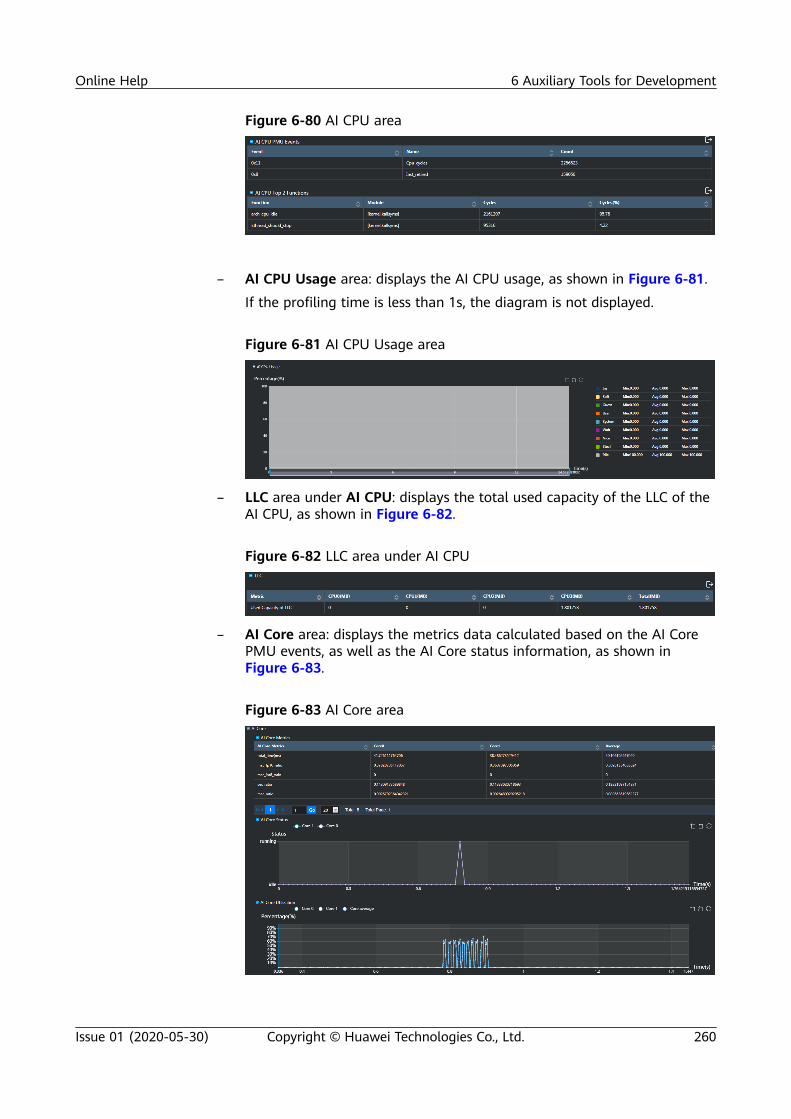
Figure 6-80 AI CPU area
– AI CPU Usage area: displays the AI CPU usage, as shown in Figure 6-81.
If the profiling time is less than 1s, the diagram is not displayed.
Figure 6-81 AI CPU Usage area
– LLC area under AI CPU: displays the total used capacity of the LLC of theAI CPU, as shown in Figure 6-82.
Figure 6-82 LLC area under AI CPU
– AI Core area: displays the metrics data calculated based on the AI CorePMU events, as well as the AI Core status information, as shown inFigure 6-83.
Figure 6-83 AI Core area
Online Help 6 Auxiliary Tools for Development
Issue 01 (2020-05-30) Copyright © Huawei Technologies Co., Ltd. 260

Status area: displays the busy/idle status of each AI Core at the samplingtime; Percentage area: displays the usage of each AI Core at thesampling time.
Online Help 6 Auxiliary Tools for Development
Issue 01 (2020-05-30) Copyright © Huawei Technologies Co., Ltd. 261

Currently, the supported default events include 0x3, 0x8, 0x9, 0xe, 0x3a, 0x3b,0x4a, and 0x49. 0x3 indicates the number of executed instructions of the cubetype. 0x8 indicates cycles for executing instructions of the vector type. 0x9indicates cycles for executing instructions of the scalar type. 0xe indicates thecycles for executing all instructions. 0x3a indicates cycles for executing scalarinstructions requesting to read the UB. 0x3b indicates cycles for executing scalarinstructions requesting to write the UB. 0x4a indicates cycles for executinginstructions of the cube int type. 0x49 indicates cycles for executing instructionsof the cube FP type.
The formulas for calculating the AI Core metrics are as follows. The ratios do notadd up to 1 because there is an inclusion relationship among them.
1. total_time indicates the time consumption based on the task cycles obtainedfrom the PMU_TASK_CYC_CNT register and the operating frequency.
2. mac_fp16_ratio indicates the execution cycle ratio of cube FP instructions toall instructions: mac_fp16_ratio = 1.0 x SUM(0x49)/SUM(PMU_TASK_CYC_CNT)
3. mac_int8_ratio indicates the execution cycle ratio of cube int instructions toall instructions: mac_int8_ratio = 1.0 x SUM(0x4a)/SUM(PMU_TASK_CYC_CNT)
4. vec_ratio indicates the execution cycle ratio of vec instructions to allinstructions: vec_ratio = 1.0 x SUM(0x8)/SUM(PMU_TASK_CYC_CNT)
5. mac_ratio indicates the ratio of cube instructions (excluding the write requestson special registers) to total instruction cycles: mac_ratio = 1.0 x SUM(0x3)/SUM(PMU_TASK_CYC_CNT)
6. scalar_ratio indicates the execution cycle ratio of scalar instructions to allinstructions: scalar_ratio = 1.0 x SUM(0x9)/SUM(PMU_TASK_CYC_CNT)
7. scalar_ld_ratio indicates the execution cycle ratio of scalar instructionsrequesting to read the UB to all instructions: scalar_ld_ratio = 1.0 x SUM(0x3a)/SUM(PMU_TASK_CYC_CNT)
8. scalar_st_ratio indicates the execution cycle ratio of scalar instructionsrequesting to write the UB to all instructions: scalar_st_ratio = 1.0 x SUM(0x3b)/SUM(PMU_TASK_CYC_CNT)
9. l1_read_bw indicates the L1 read bandwidth rate: 1.0 x SUM(r31) x 256.0 x16.0/total_time/8.0 x 2.0^30.0 (r31 event is l1_read_req)
10. l1_write_bw indicates the L1 write bandwidth rate: 1.0 x SUM(r32) x 256.0 x8.0/total_time/8.0 x 2.0^30.0 (r32 event is l1_write_req)
11. l2_read_bw indicates the L2 read bandwidth rate: 1.0 x SUM(rf) x 256.0 x8.0/total_time/8.0 x 2.0^30.0 (rf event is l2_read_req)
12. l2_write_bw indicates the L2 write bandwidth rate: 1.0 x SUM(r10) x 256.0 x8.0/total_time/8.0 x 2.0^30.0 (r10 event is l2_write_req)
13. hbm_read_bw indicates the HBM read bandwidth rate: 1.0 x SUM(r12) x256.0 x 8.0/total_time/8.0 x 2.0^30.0 (r12 event is hbm_read_req)
14. hbm_write_bw indicates the HBM write bandwidth rate: 1.0 x SUM(r13) x256.0 x 8.0/total_time/8.0 x 2.0^30.0 (r13 event is hbm_write_req)
15. vec_bankgroup_cflt_ratio indicates the execution cycle ratio ofvec_bankgroup_stall_cycles instructions to all instructions: 1.0 x SUM(r64)/SUM(PMU_TASK_CYC_CNT) (r64 event is vec_bankgroup_cflt_ratio)
16. vec_bank_cflt_ratio indicates the execution cycle ratio ofvec_bank_stall_cycles instructions to all instructions: 1.0 x SUM(r65)/SUM(PMU_TASK_CYC_CNT) (r65 event is vec_bank_cflt_ratio)
17. vec_resc_cflt_ratio indicates the execution cycle ratio of vec_resc_cflt_ratioinstructions to all instructions: 1.0 x SUM(r66)/SUM(PMU_TASK_CYC_CNT) (r66event is vec_resc_cflt_ratio)
Online Help 6 Auxiliary Tools for Development
Issue 01 (2020-05-30) Copyright © Huawei Technologies Co., Ltd. 262
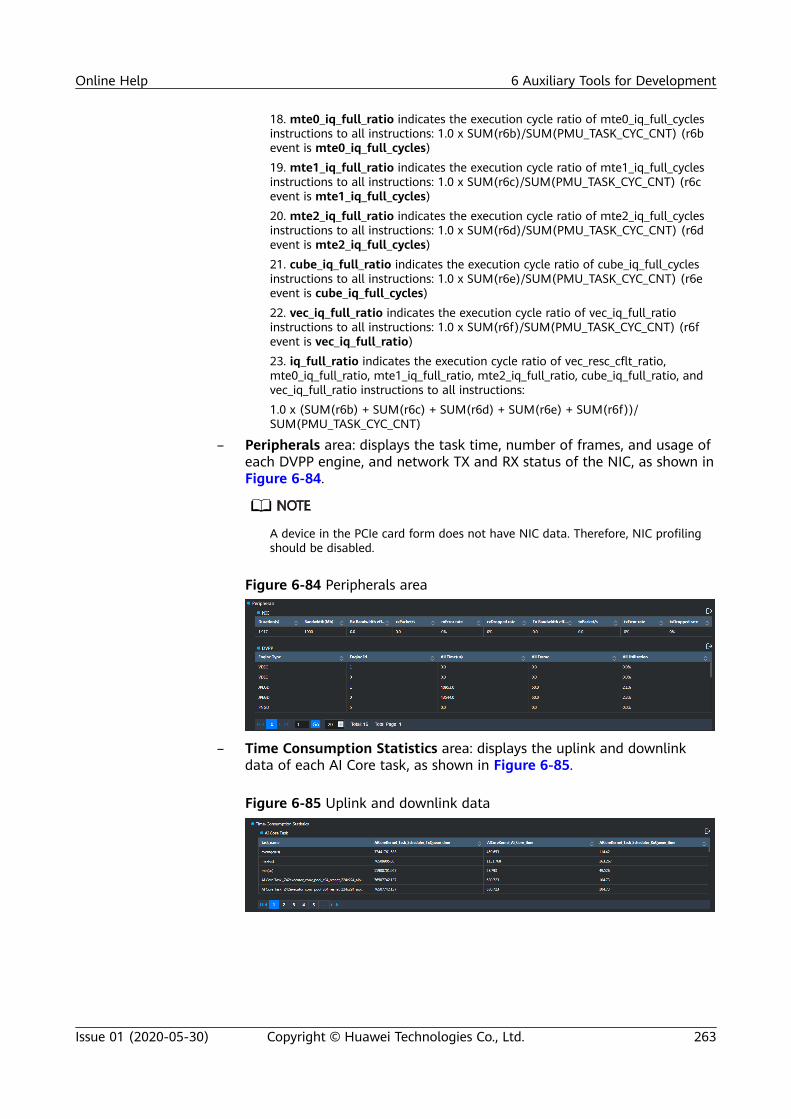
18. mte0_iq_full_ratio indicates the execution cycle ratio of mte0_iq_full_cyclesinstructions to all instructions: 1.0 x SUM(r6b)/SUM(PMU_TASK_CYC_CNT) (r6bevent is mte0_iq_full_cycles)19. mte1_iq_full_ratio indicates the execution cycle ratio of mte1_iq_full_cyclesinstructions to all instructions: 1.0 x SUM(r6c)/SUM(PMU_TASK_CYC_CNT) (r6cevent is mte1_iq_full_cycles)20. mte2_iq_full_ratio indicates the execution cycle ratio of mte2_iq_full_cyclesinstructions to all instructions: 1.0 x SUM(r6d)/SUM(PMU_TASK_CYC_CNT) (r6devent is mte2_iq_full_cycles)21. cube_iq_full_ratio indicates the execution cycle ratio of cube_iq_full_cyclesinstructions to all instructions: 1.0 x SUM(r6e)/SUM(PMU_TASK_CYC_CNT) (r6eevent is cube_iq_full_cycles)22. vec_iq_full_ratio indicates the execution cycle ratio of vec_iq_full_ratioinstructions to all instructions: 1.0 x SUM(r6f)/SUM(PMU_TASK_CYC_CNT) (r6fevent is vec_iq_full_ratio)23. iq_full_ratio indicates the execution cycle ratio of vec_resc_cflt_ratio,mte0_iq_full_ratio, mte1_iq_full_ratio, mte2_iq_full_ratio, cube_iq_full_ratio, andvec_iq_full_ratio instructions to all instructions:1.0 x (SUM(r6b) + SUM(r6c) + SUM(r6d) + SUM(r6e) + SUM(r6f))/SUM(PMU_TASK_CYC_CNT)
– Peripherals area: displays the task time, number of frames, and usage ofeach DVPP engine, and network TX and RX status of the NIC, as shown inFigure 6-84.
A device in the PCIe card form does not have NIC data. Therefore, NIC profilingshould be disabled.
Figure 6-84 Peripherals area
– Time Consumption Statistics area: displays the uplink and downlinkdata of each AI Core task, as shown in Figure 6-85.
Figure 6-85 Uplink and downlink data
Online Help 6 Auxiliary Tools for Development
Issue 01 (2020-05-30) Copyright © Huawei Technologies Co., Ltd. 263

Table 6-11 Parameters of uplink and downlink data of AI Core tasks
Parameter Description
task_name Kernel function name
AiCoreKernel_Task_Scheduler_TxQueue_time
Time taken to run the task on the AI Core after TStask scheduling
AiCoreKernel_AI_Core_time
Time that a task runs on the AI Core
AiCoreKernel_Task_Scheduler_RxQueue_time
Time that a task is scheduled by the TS afterrunning on the AI Core
6.3.2.3.2 Timeline
The Timeline tab displays the performance timelines of the RTS, Matrix, OME,CCE, and Peripherals, as shown in Figure 6-86.
● The pending, waiting, and running states in the upper left corner of Figure 6-86indicate the state duration of the RTS tasks. These states are valid only for the stream,scheduling, and compute tasks of the RTS module. An RTS compute task has thepreceding three states, while an RTS stream or scheduling task has only the runningstate.
● An RTS compute task may be in the running, waiting->running, or waiting->pendingstate.
● The time blocks of other modules indicate the state duration of the correspondingmodules. Different colors are used for differentiation. For example, the white and lightblue colors of a thread are used to differentiate the calling different APIs.
● When you drag the progress bar in the upper right corner of the page, the pagerequests data again. Some modules are not displayed in the time segment if no relateddata is available.
Figure 6-86 Performance timelines
1. The RTS area consists of the following parts:– Thread: timeline information when each thread invokes the runtime APIs,
as shown in Figure 6-87.
Online Help 6 Auxiliary Tools for Development
Issue 01 (2020-05-30) Copyright © Huawei Technologies Co., Ltd. 264

Figure 6-87 Thread area
– Scheduling: runtime timeline information of tasks scheduled by the TaskScheduler, as shown in Figure 6-88.
Figure 6-88 Scheduling area
– Compute: runtime timeline information about the kernel functions onthe AI Core. You can click the rectangle of each kernel function to view itsstart runtime and end runtime and the AI Core PMU value collected intask-based mode, as shown in Figure 6-89.
Figure 6-89 Compute area
– Streams: task runtime timeline information in the streams, including theinformation about inter-stream synchronization, as shown in Figure 6-90.
Figure 6-90 Streams area
2. Matrix area: displays the runtime start and end of each engine, as shown inFigure 6-91.
Online Help 6 Auxiliary Tools for Development
Issue 01 (2020-05-30) Copyright © Huawei Technologies Co., Ltd. 265

Figure 6-91 Matrix analysis
3. OME area: displays the start runtime, end runtime, and other information ofeach operator, as shown in Figure 6-92.
Figure 6-92 OME area
4. Peripherals area: displays the peripheral information, including the task timeand number of task frames of each engine of the DVPP. The TX and RXnetwork performance of the NIC at each moment is also displayed, as shownin Figure 6-93.
Figure 6-93 Peripherals area
The indicators in the NIC chart are described as follows:– rxPacket/s: indicates the packet RX rate per second.– rxError rate: indicates the error rate of received packets.– rxDropped rate: indicates the packet loss rate of received packets.– Rx Bandwidth efficiency(%): indicates the bandwidth usage of received
packets.– txPacket/s: indicates the packet TX rate per second.– txError rate: indicates the error rate of transmitted packets.– txDropped rate: indicates the packet loss rate of transmitted packets.
Online Help 6 Auxiliary Tools for Development
Issue 01 (2020-05-30) Copyright © Huawei Technologies Co., Ltd. 266

– Tx Bandwidth efficiency(%): indicates the bandwidth usage oftransmitted packets.
The indicators in the DVPP chart are described as follows:– proc_time: indicates the engine usage time in each sampling interval.– last_time: indicates the time when the last task is consumed.– proc_frame: indicates the number of frames processed by the engine in
each sampling interval.– last_frame: indicates the number of frames of the last task.– proc_utilization: indicates the time window usage, that is, the
accumulated processing time divided by the runtime.– all_utilization: indicates the average usage, that is, the accumulated
processing time divided by the runtime.5. LLC area: displays the read/write bandwidth and hit ratio of the LLC at each
moment, including the LLC capacity used by the Ctrl CPU and AI CPU at eachmoment, as shown in Figure 6-94.
Figure 6-94 LLC area
6. DDR area: displays the DDR information.
Figure 6-95 DDR area
7. RTStrack area: displays the uplink and downlink data of each AI Core task, asshown in Figure 6-96.
Figure 6-96 RTStrack area
Online Help 6 Auxiliary Tools for Development
Issue 01 (2020-05-30) Copyright © Huawei Technologies Co., Ltd. 267

1. The time blocks in all timeline charts can be zoomed in or out by using the scrollwheel. You can also find the zoom in, zoom out, and restoration buttons in the upperright corner.2. After zooming in, you can press and hold the left mouse button and drag a timeblock to view the details.
6.3.2.3.3 Control CPU Function
As long as Control CPU Profiling is enabled in the Hardware configuration area,the Control CPU Function tab is generated.
The top functions of the control CPU during profiling are ranked by Cycles bydefault, as shown in Figure 6-97.
You can click next to the table to export the data to an Excel file on the localPC.
Figure 6-97 Control CPU Function tab page
6.3.2.3.4 AI CPU Function
As long as Al CPU Profiling is enabled in the Hardware configuration area, the AlCPU Function tab page is generated.
The top functions of the Al CPU during profiling are ranked by Cycles by default,as shown in Figure 6-98.
You can click next to the table to export the data to an Excel file on the localPC.
Online Help 6 Auxiliary Tools for Development
Issue 01 (2020-05-30) Copyright © Huawei Technologies Co., Ltd. 268

Figure 6-98 Al CPU Function tab page
6.3.3 Full-Process Profiling in CLI ModeTo analyze performance data in command line mode, log in to the Mind Studioserver as the Mind Studio installation user and run the commands in the script ~/tools/che/ddk/ddk/toolchains/profiler/analysis/msvp/host/bin64/hiprof.pyc toprofile performance data. After successful profiling, you can view the performanceanalysis results in CLI mode.
● ~/tools is the default toolpath path, which can be customized during Mind Studioinstallation.
Profiling Performance DataThe following uses the data on process orchestration as an example to describehow to profile the performance data.
Step 1 Log in to the Mind Studio server as the Mind Studio installation user.
Step 2 Go to the directory of the hiprof.pyc script, for example: ~/tools/che/ddk/ddk/toolchains/profiler/analysis/msvp/host/bin64
Step 3 Profile software and hardware data in sample-based mode and task-based moderespectively.
In the following commands, --ai_core_profiling_mode=sample-based indicatesthe sample-based mode. Replace x.x.x.x with the IP address of the server wherethe host is located.
After the command is executed, the configuration parameters in the command aresaved in the sample.ini file by default. The file is saved in the directory specifiedby result_dir. For details about the parameters in the command line, see Table6-12. You must set the parameters according to the description.● Commands for profiling all software and hardware data in sample-based
mode.python hiprof.pyc --ip_address=x.x.x.x --ddk_dir=/home/ascend/tools/che/ddk/ddk --app=/home/ascend/tools/projects/MIND/out/main --app_dir=/home/ascend/tools/projects/MIND/ --umode=MIND --result_dir=/home/ascend/tools/out --peripheral_profiling=nic,dvpp --
Online Help 6 Auxiliary Tools for Development
Issue 01 (2020-05-30) Copyright © Huawei Technologies Co., Ltd. 269

ai_cpu_profiling=on --RTS_Profiling=on --ai_core_profiling_mode=sample-based --ai_core_profiling=on --HIAI_Engine_Profiling=on --aicore_metrics=mac_fp16_ratio,mac_int8_ratio --OME_Profiling=on --topN=50 --pid=10 --ctrl_cpu_profiling=on --profiling_mode=online --llc_bandwidth=on --ddr_profiling=on
● Commands for profiling all software and hardware data in task-based mode.python hiprof.pyc --ip_address=x.x.x.x --ddk_dir=/home/ascend/tools/che/ddk/ddk --app=/home/ascend/tools/projects/MIND/out/main --app_dir=/home/ascend/tools/projects/MIND/ --umode=MIND --result_dir=/home/ascend/tools/out --peripheral_profiling=nic,dvpp --ai_cpu_profiling=on --RTS_Profiling=on --ai_core_profiling_mode=task-based --ai_core_profiling=on --HIAI_Engine_Profiling=on --aicore_metrics=mac_fp16_ratio,mac_int8_ratio --OME_Profiling=on --topN=50 --pid=10 --ctrl_cpu_profiling=on --profiling_mode=online --llc_bandwidth=on --ddr_profiling=on
● In task-based mode, run the command with parameters to profile data. Thistype of case is user-defined. In this scenario, the app parameters and appinput parameters must be placed at the end of the command line. Thefollowing is an example: /home/ascend/tools/projects/CCE_BBIT/out/mainindicates the path and name of the custom app, and RTS_SINK_2001indicates the parameters that need to be set for the app.python hiprof.pyc --ip_address=x.x.x.x --ddk_dir=/home/ascend/tools/che/ddk/ddk --app_dir=/home/ascend/tools/projects/CCE_BBIT/out/--umode=MIND --result_dir=/home/ascend/tools/out --ai_cpu_profiling=on --RTS_Profiling=on --ai_core_profiling=on --ctrl_cpu_profiling=on --profiling_mode=online --aicore_metrics=mac_fp16_ratio,mac_int8_ratio --topN=50 --pid=10 -- /home/ascend/tools/projects/CCE_BBIT/out/main RTS_SINK_2001
● Profiling (CLI) supports fuzzy matching. For any command parameter, entering a correctprefix without ambiguity can trigger proper execution, for example:
Calling --aicore_metri equivalent to calling --aicore_metrics.
● If the error message "Data folder is locked" is reported during the command execution,the possible cause is that the Profiling command exits abnormally last time. Delete theoutput result folder and try again.
● The following special characters are not supported in the CLI: [';*?`!#$%^&+=<>{}]|"
----End
Viewing Performance Analysis Results1. System AI CPU and Ctrl CPU usage and system memory information
Figure 6-99 AI CPU and Ctrl CPU usage
Online Help 6 Auxiliary Tools for Development
Issue 01 (2020-05-30) Copyright © Huawei Technologies Co., Ltd. 270

Figure 6-100 System memory
2. Runtime API calls and Task Scheduler information
Figure 6-101 Runtime API calls
Figure 6-102 Task Scheduler
3. Ctrl CPU PMU Events
Figure 6-103 Ctrl CPU PMU Events
4. Control CPU Top Functions
Figure 6-104 Ctrl CPU Top Functions
5. AI CPU PMU Events
Online Help 6 Auxiliary Tools for Development
Issue 01 (2020-05-30) Copyright © Huawei Technologies Co., Ltd. 271

Figure 6-105 AI CPU PMU Events
6. AI CPU Top Function
Figure 6-106 AI CPU Top 2 Functions
7. TS CPU PMU Events
Figure 6-107 TS CPU PMU Events
8. AI Core data Matrices
Online Help 6 Auxiliary Tools for Development
Issue 01 (2020-05-30) Copyright © Huawei Technologies Co., Ltd. 272

Figure 6-108 AI Core data Matrices
9. NIC Data
Figure 6-109 Nic Data
10. DVPP Data
Figure 6-110 Dvpp data
Online Help 6 Auxiliary Tools for Development
Issue 01 (2020-05-30) Copyright © Huawei Technologies Co., Ltd. 273

11. Matrix data information (When the number of data records is greater than100, only the first 100 data records are displayed.)
Figure 6-111 Matrix Information
12. OME Data
Figure 6-112 OME Information
13. LLC Data
Figure 6-113 LLC data
14. DDR Data
Online Help 6 Auxiliary Tools for Development
Issue 01 (2020-05-30) Copyright © Huawei Technologies Co., Ltd. 274

Figure 6-114 DDR area
15. Memory and CPU usage of top N processes
Figure 6-115 Memory and CPU usage of processes
16. Memory usage and CPU usage of a specified PID process
Figure 6-116 Memory usage
Online Help 6 Auxiliary Tools for Development
Issue 01 (2020-05-30) Copyright © Huawei Technologies Co., Ltd. 275

Figure 6-117 CPU usage
Follow-up OperationsYou can also import profiling results to Profiling on the profiling main page. Theprocedure is as follows:
Step 1 Go to https://IP address of the Profiling server:8099 using a browser. Log in tothe Profiling page. The default account name is msvpadmin and the password isAdmin12#$. After login, choose Import Results from the Analysis drop-down listbox on the upper left of the page, as shown in Figure 6-118.
Figure 6-118 Choosing Import Results
Step 2 In the dialog box that is displayed, enter the path of the profiling results in thePath text box and click OK, as shown in Figure 6-119.
The value of Path must be the same as the value of result_dir in the commandline.
Figure 6-119 Importing the profiling result
----End
sample.ini FileThe content of the sample.ini file is as follows:
[GENERAL]analysis_type=aianalysis_target=Launch Applicationresult_dir=/home/ascend/tools/outumode=MINDprofiling_mode=onlineHIAI_Engine_Profiling=on
Online Help 6 Auxiliary Tools for Development
Issue 01 (2020-05-30) Copyright © Huawei Technologies Co., Ltd. 276

Framework_Profiling=onRTS_Profiling=onlocal_app_dir=/home/ascend/tools/projects/MIND0126_02local_app=/home/ascend/tools/projects/MIND0126_02/out/mainapp_parameters=cpu_profiling_interval=20ctrl_cpu_profiling=onts_cpu_profiling=offai_cpu_profiling=onai_core_profiling=onai_core_profiling_interval=10ai_core_profiling_mode=task-basedcustom_pid=10topN=50peripheral_profiling=nicperipheral_profiling_interval=10ai_core_profiling_metrics=mac_fp16_ratio,mac_int8_ratioai_core_profiling_events=0x4a,0x9llc_capacity=onllc_bandwidth=offllc_interval=100ddr_profiling=onddr_interval=100ddr_master_id=3
app_dir=/home/HwHiAiUser/HIAI_PROJECTS/66adc0ebcb506226f153262feb4f7c7c//MIND0126_02/outapp=hiai_66adc0ebcb506226f153262feb4f7c7c_MIND0126_02_mainctrl_cpu_profiling_events=0x11,0x8ai_cpu_profiling_events=0x11,0x8ts_cpu_profiling=offllc_profiling_events=hisi_l3c0_1/dsid0/,hisi_l3c0_1/dsid1/,hisi_l3c0_1/dsid2/,hisi_l3c0_1/dsid3/,hisi_l3c0_1/dsid4/,hisi_l3c0_1/dsid5/,hisi_l3c0_1/dsid6/,hisi_l3c0_1/dsid7/ddr_profiling_events=read,writestream_enabled=oncleanup_host_results=oncleanup_device_results=onddk_dir=/home/ascend/tools/che/ddk/ddkllc_profiling=onjob_id=b8380eea-236c-11e9-8354-286ed488e3a7devices=0
Table 6-12 describes the key parameters.
Table 6-12 Key parameters
Parameter Description Mandatory orNot
profiling_mode
Profiling mode. The value online indicates that the app runs on the host,while the value offline indicates that the app runs on the device.NOTE
The released version does not support offline profiling. This parameter can only beset to online.
Yes
ddk_dir DDK installation directory (which must exist). Yes
ip_address IP address of the host. This parameter is not recorded in sample.ini forsecurity purposes.
Yes
Online Help 6 Auxiliary Tools for Development
Issue 01 (2020-05-30) Copyright © Huawei Technologies Co., Ltd. 277

Parameter Description Mandatory orNot
umode Project mode. The value MIND indicates a project created using MindStudio or in DDK CLI mode. To use Profiling to profile data, the value ofprofiling_mode must be online.The value CCE indicates a CCE operator app.
Yes
app_dir Directory of the application project on the Mind Studio server, includingthe project name. This parameter is mandatory and the directory mustexist.Example: --app_dir /home/ascend/tools/projects/MIND0126_02NOTE
The specified directory must be in the Mind Studio installation directory. Ensure thatthe Mind Studio installation user has the read and write permissions on thedirectory. Same for the directory specified by the app parameter.
Yes
app Directory of the application executable file on the Mind Studio server,including the project name. This parameter is mandatory and thedirectory must exist.Example: --app /home/ascend/tools/projects/MIND0126_02/out/main
Yes
devices Device list. The default value is 0.This parameter is required only in CCE scenarios.
No
OME_Profiling
Whether to enable OME profiling. The default setting is OFF.In sample.ini, this item is displayed as Framework_Profiling.
No
HIAI_Engine_Profiling
Whether to enable profiling for the Matrix module. The default setting isOFF.
No
CCE_Profiling Whether to enable profiling for the CCE module. The default setting isOFF.
No
peripheral_profiling_interval
Peripheral profiling interval. The value range is [1, 1000]. The defaultvalue is 10.
No
peripheral_profiling
Peripheral profiling mode: dvpp, nic, or both. A comma (,) must be usedto separate them. This parameter is left blank by default.
No
ctrl_cpu_profiling
Whether to enable profiling for the Ctrl CPU. The default setting is OFF. No
ts_cpu_profiling
Whether to enable profiling for the TS CPU. The default setting is OFF. No
ai_cpu_profiling
Whether to enable profiling for the AI CPU. The default setting is OFF. No
ai_core_profiling
Whether to enable profiling for the AI Core. The default setting is OFF. No
Online Help 6 Auxiliary Tools for Development
Issue 01 (2020-05-30) Copyright © Huawei Technologies Co., Ltd. 278

Parameter Description Mandatory orNot
ai_core_profiling_mode
AI Core profiling mode. The value can be task-based or sample-based. Intask-based mode, data is profiled by task. In sample-based mode, data isprofiled by sample. The default setting is task-based.
No
ai_core_profiling_interval
Profiling interval when the AI Core profiling mode is sample-based. Thevalue range is [1, 1000]. The default value is 10.
No
aicore_metrics
In the command line, aicore_metrics is used to specify the events to beprofiled each time. A maximum of eight events are supported. Separatethem using commas (,). For details about the profiling event, see AI Corearea.In sample.ini, the value of ai_core_profiling_metrics is the same as thatof aicore_metrics in the command line.Currently, the following events can be specified:mac_fp16_ratio, mac_int8_ratio, vec_ratio, mac_ratio, scalar_ratio,scalar_ld_ratio, scalar_st_ratio, l1_read_bw, l1_write_bw, l2_read_bw,l2_write_bw, hbm_read_bw, hbm_write_bw, vec_bankgroup_cflt_ratio,vec_bank_cflt_ratio, vec_resc_cflt_ratio, mte0_iq_full_ratio,mte1_iq_full_ratio, mte2_iq_full_ratio, cube_iq_full_ratio, vec_iq_full_ratio,iq_full_ratio
No
pid In the command line, pid specifies the memory and CPU usage of aspecified PID to be displayed after each profiling. The pid parametersupports only one input.In sample.ini, the value of custom_pid is the same as that of pid in thecommand line.
No
topN In the command line, topN specifies the top N processes to be displayedby memory and CPU usage in descending order after each profiling.In sample.ini, the value of topN is the same as that of topN in thecommand line.
No
RTS_Profiling Whether to enable RTS profiling. No
result_dir Directory of the profiling results. Ensure that the Mind Studio installationuser has the read and write permissions on the directory. Set result_dir toa directory in the home directory ~/tools/ of the Mind Studio installationuser.If the directory does not exist, the system automatically creates one. If thedirectory exists, the system adds the .old suffix to the directory name.
No
cpu_profiling_interval
CPU profiling interval. This parameter is mandatory if the interval isrequired. The value range is [20, 1000]. The default value is 20.
No
Online Help 6 Auxiliary Tools for Development
Issue 01 (2020-05-30) Copyright © Huawei Technologies Co., Ltd. 279

Parameter Description Mandatory orNot
import Imports profiling result file to the database by calling mvsp_import.pyc.You need to configure the project file path. A profiling result file must bestored in a directory under Home directory of the Mind Studioinstallation user/tools/. Otherwise, the file cannot be imported. Thisparameter is not saved in sample.ini.The python hiprof.pyc command can contain only the import parameter.
No
report Prints the profiling result.In the python hiprof.pyc command line, contain the report parameterand add the absolute path of the profiling result to be printed. Example:python hiprof.pyc --report /home/ascend/tools/projects/test/profiling_output/
No
llc_bandwidth
Whether to enable read/write bandwidth profiling for the LLC. The defaultsetting is OFF. This parameter is mutually exclusive with llc_capacity.Only one type of LLC data can be profiled at a time.
No
llc_capacity Whether to enable LLC usage profiling. The default setting is OFF. Thisparameter is mutually exclusive with llc_bandwidth. Only one type of LLCdata can be profiled at a time.
No
llc_interval LLC profiling interval. This parameter is mandatory if the interval isrequired. The value range is [100, 1000]. The default value is 100 (ms).
No
ddr_profiling Whether to enable profiling for the DDR SDRAM. No
ddr_master_id
Whether to enable read/write bandwidth profiling for the AI CPU and CtrlCPU core. This parameter is left blank by default. The value range is 0–7.0–3 correspond to the core IDs of the Ctrl CPU. 4–7 correspond to the coreIDs of the AI CPU.
No
ddr_interval DDR profiling interval. This parameter is mandatory if the interval isrequired. The value range is [100, 1000]. The default value is 100 (ms).
No
all Whether to enable profiling for all performance. The default setting isOFF.
No
help Help information No
Online Help 6 Auxiliary Tools for Development
Issue 01 (2020-05-30) Copyright © Huawei Technologies Co., Ltd. 280

● Ensure that all paths of result_dir have the 750 permission.
● The input format of the operators with parameters is: -- Path where the app file isstored in the UI host (including the app name) para1 para2. (para1 para2 are theparameters of the app) Example: -- /home/ascend/tools/projects/CCE/out/main para1para2 If Path where the app file is stored in the UI host (including the app name)para1 para2 is added to the command line for performance data profiling, thisparameter must be placed at the end of the command line and the --app parametermust be deleted from the command line, otherwise, a parsing error occurs.
● It is recommended that the DDR and LLC sampling intervals be not greater than thetime required for program execution. Otherwise, data cannot be profiled.
● If the profiling time is less than 1s, the Control CPU Usage, AI CPU Usage, and TS CPUUsage charts are not displayed.
6.3.4 Reference
6.3.4.1 Function to Source Code Redirection
Configure the Control CPU Binary/Symbol Search and Control CPU C/C++Source Search paths on the Configuration tab page. On the Control CPUFunction tab page, select Module/Fucntion/Callstack in the Grouping area,double-click the function name to redirect to the source code of the correspondingfunction.
Configure the Al CPU Binary/Symbol Search path on the Configuration tabpage. On the Al CPU Function tab page, select Module/Fucntion/Callstack in theGrouping area, double-click the function name to redirect to the source code ofthe corresponding function.
● To enable this feature, the following requirement must be met before binarycompilation: The code must contain the symbol information (not striped). That is, usethe debug version compiled by using the -g option and the address randomizationcompilation options such as -pie, -fpic, -fPIC, -fpie, and -fPIE cannot be used.Otherwise, the source code path cannot be obtained after the addr2line command isexecuted.
● A compiled app using Mind Studio cannot use this feature. User-defined .so binary filesare supported. The .so files must be compiled based on the preceding parameterrequirements.
● A project file that meets the preceding conditions can be configured the feature offunction to source code redirection.
The procedure is as follows:
Step 1 Go to the Control CPU Function tab page, select Module/Fucntion/Callstack,view the path of the binary application file to which the function belongs on thedevice, and record the path.
For example, in the example shown in Figure 6-120, the binary application filelibcrypto.so.1.1 is stored in the /usr/lib64 directory on the device.
Online Help 6 Auxiliary Tools for Development
Issue 01 (2020-05-30) Copyright © Huawei Technologies Co., Ltd. 281

Figure 6-120 Viewing the path of the binary app file
Step 2 Log in to the Mind Studio server as the Mind Studio installation user and obtainthe aarch64-linux-gnu-objdump and aarch64-linux-gnu-addr2line tools from the~/tools/che/ddk/ddk/toolchains/aarch64-linux-gcc6.3/bin directory. Run thefollowing commands:
./aarch64-linux-gnu-objdump -S binary file path: Obtains the address of theassembly instructions.
./aarch64-linux-gnu-addr2line -ie libcrypto.so.1.1 Specific assembly instructionaddress: Obtains the source code path.
● ~/tools is the default toolpath setting, which can be customized during Mind Studioinstallation. You can view the value of toolpath in the scripts/env.conf file. You can runthe find / -name 'env.conf' command to view the location of the env.conf file in thescript directory.
● objdump and addr2line are third-party open source tools. You can look up theparameters of them yourself.
● In the developer board scenario, you can obtain the aarch64-linux-gnu-objdump andaarch64-linux-gnu-addr2line tools from the /usr/bin directory in the Mind Studio server.
Step 3 Go to the Configuration tab and click Modify next to Control CPU Binary/Symbol Search. Set the path to the tools path of the Mind Studio installationdirectory in the server, for example, /home/ascend/tools/demo.
Figure 6-121 Modifying the path
Online Help 6 Auxiliary Tools for Development
Issue 01 (2020-05-30) Copyright © Huawei Technologies Co., Ltd. 282

Step 4 Similarly, click Modify next to Control CPU C/C++ Source Search. Set the path tothe tools path of the Mind Studio installation directory in the server, forexample, /home/ascend/tools/demo.
Step 5 Create the binary file path recorded in Step 3 in the path configured in Step 1.Create the source code path recorded in Step 4 in the path configured in Step 2.
For example, create the usr/lib64 directory in ~/tools/demo.
● If the binary file path and source code path are not in the standard Linux absolute pathformat, directly save the binary file and source code in the Step 3 root directory of theconfiguration path.
● If the binary file path and source code path contain invalid characters such as [ \ ' ; * ? ~` ! @ # $ % ^ & + = ) ( < > { } ] | ", the function cannot be used.
Step 6 Copy the binary files on the device side to the directory created in Step 5, forexample, ~/tools/demo/usr/lib64.
Step 7 Go to the Control CPU Function tab and double-click any function in the redframe. The assembly code and source code corresponding to the function isdisplayed.
Figure 6-122 Redirecting to the source code
Step 8 Configure function redirection on the Al CPU Function tab page. For details, seeControl CPU Function redirection configuration.
Figure 6-123 Configuration tab page
Online Help 6 Auxiliary Tools for Development
Issue 01 (2020-05-30) Copyright © Huawei Technologies Co., Ltd. 283

The Al CPU C/C++ Source Search parameter is not used in any scenarios.
----End
6.3.4.2 Password Reset for Connecting to the Redis Service
Out of security considerations, you are advised to reset the password forconnecting to the Redis service periodically (for example, every 90 days). Thedefault password is Huawei12#$.
Step 1 Log in to the Mind Studio server as the Mind Studio installation user.
Step 2 Go to the tools/profiler directory and run the following command to reset thepassword:
dir indicates the installation path of Profiling, and ~ must be replaced with thehome directory of the Mind Studio installation user../install_profiling.sh --reset_redis_pwd --dir=~/tools/profiler
● ~/tools is the default toolpath setting, which can be customized during Mind Studioinstallation. You can view the value of toolpath in the scripts/env.conf file. You can runthe find / -name 'env.conf' command to view the location of the env.conf file in thescript directory.
Enter the new password twice as prompted, as shown in Figure 6-124.
A new password must meet the following requirements:
● The password must contain at least six characters.● A password is a combination of at least two types of the following:
– At least one lowercase letter– At least one uppercase letter– At least one digit– At least one space or one of the following special characters: ` ~ ! @ # $
% ^ & * ( ) - _ = + \ | [ { } ] ; : ' " , < . > / ?
Figure 6-124 Entering the new password
If the information shown in Figure 6-125 is displayed, the password is resetsuccessfully.
Figure 6-125 Password reset successfully
----End
Online Help 6 Auxiliary Tools for Development
Issue 01 (2020-05-30) Copyright © Huawei Technologies Co., Ltd. 284

6.3.4.3 Script ListTo execute a script in Table 6-13, perform the following steps:
1. Log in to the Mind Studio server as the Mind Studio installation user.2. Go to the ~/tools/che/ddk/ddk/toolchains/profiler/analysis/msvp/host/
bin64 directory.
● ~/tools is the default toolpath path, which can be customized during Mind Studioinstallation.
● The following special characters are not supported when you run the followingscript commands: [';*?`!#$%^&+=<>{}]|"
3. Run a command listed in Table 6-13 to call a tool.
Table 6-13 Script list
Script Function Parameter and Example
get_env_info.pycVerifies a folderor deletes a file orfolder.
Verifies if a foldercomplies with theimportspecifications.
--verify/-v <Folder>Example: python get_env_info.pyc -v /home/msvptest/tools/projects_name
Deletes a file orfolder.
--remove/-r <File>Example: python get_env_info.pyc -r /home/whl/info.xml
Views the helpinformation.
-h/--help
Online Help 6 Auxiliary Tools for Development
Issue 01 (2020-05-30) Copyright © Huawei Technologies Co., Ltd. 285

Script Function Parameter and Example
get_msvp_function.pycObtains data onthe Function tabpage based onthe specifiedproject, modulename, andfunction name.
Specifies a projectand obtains dataof all data typeson the Functiontab page.
● --project <Project folder>: Thisparameter is mandatory.
● --target <Data type>: It can be setto total, core, thread, module,function, callstack, export, class,classmethod, exportfunc,exportmodule, exportcore, orexporttid.
● --deviceid=<Device ID>● --type <CPU type>: It can be set to
ctrlcpu or aicpu.● --order/-o <Indicator order>: It
can be set to cycles.● --core/-c <Number of CPU cores>:
Filters results by core.● --pid/-p <pid>: Filters results by
process ID● --tid/-t <tid>: Filters results by
thread ID.● --sort/-s <Sorting order>: It can be
set to ASC (ascending order) orDESC (descending order).
● --limit/-l <Result count>● --export/-e: If this parameter is
added, the result is to be exported.Example: pythonget_msvp_function.pyc --project /home/msvptest/tools/projects_name--target total --deviceid=0 --type=ctrlcpu -o cycles -c 1 -p 1 -t 1 -s DESC -l 1 -e
Specifies theproject andmodule name, andobtains the datawhose data type isfunction on theFunction tabpage.
--module/-m <Module name>Example: /home/whl/analysis/msvp/host/bin64# pythonget_msvp_function.pyc --project /home/msvptest/tools/projects_name--target function -m /usr/lib64/libc-2.17.so --type ctrlcpu --deviceid=0
Online Help 6 Auxiliary Tools for Development
Issue 01 (2020-05-30) Copyright © Huawei Technologies Co., Ltd. 286

Script Function Parameter and Example
Specifies projectand functionname, and obtainsthe data whosedata type iscallstack on theFunction tabpage.
--function/-f <Function name>Example: pythonget_msvp_function.pyc --project /home/msvptest/tools/projects_name--target callstack -f_dl_relocate_object --type ctrlcpu --deviceid=0
Views the helpinformation.
-h/--help
get_msvp_info.pycObtains data onthe Summary tabpage of aspecified project.
Obtains the CPUusage of aspecified CPU onthe Summary tabpage
● --project <Project folder>: Thisparameter is mandatory.
● --deviceid=<Device ID>● --cpuusage: Obtains the CPU
usage of a specified type of CPUs,which is used together with --type.
● --type <CPU type>: It can be set toaicpu or ctrlcpu.
● --startTime=<Start time>:Specifies the start time for scaling.If the profiling period is 10s, --startTime=0 indicates that theprofiling starts from 0s.
● --endTime=<End time>: Specifiesthe end time for scaling. If theprofiling period is 10s, --endTime=6 indicates that theprofiling ends at 6s.
● --number <Maximum number ofdata records displayed on apage>
Example: python get_msvp_info.pyc--project /home/msvptest/tools/projects_name --deviceid=0 --cpuusage --type ctrlcpu --startTime=0 --endTime=6 --number1000
ObtainsCollection Info onthe Summary tabpage.
--collection_infoExample: python get_msvp_info.pyc--project /home/msvptest/tools/projects_name --deviceid=0 --typeaicpu --collection_info
Online Help 6 Auxiliary Tools for Development
Issue 01 (2020-05-30) Copyright © Huawei Technologies Co., Ltd. 287

Script Function Parameter and Example
Obtains Host Infoon the Summarytab page.
--host_infoExample: python get_msvp_info.pyc--project /home/msvptest/tools/projects_name --deviceid=0 --typeaicpu --host_info
Obtains the deviceID.
--msvp_deviceExample: python get_msvp_info.pyc--project /home/msvptest/tools/projects_name --msvp_device
Obtainsinformation of adevice.
--msvp_deviceinfoExample: python get_msvp_info.pyc--project /home/msvptest/tools/projects_name --msvp_deviceinfo --deviceid=0
Obtains theruntime API data.
--runtime_apiExample: python get_msvp_info.pyc--project /home/msvptest/tools/projects_name --runtime_api --deviceid=0
Obtains theoperator data ofthe framework.
● --framework_op● --limitPage <Number of records
to be displayed on each page>● --page <Page to be obtained>● --sortColName <Column to be
sorted>: This parameter is optional.It can be set to op_names,fusion_op_nums, modelname,model_id, stream_id, op_start,op_end, op_en, memory_input,memory_output, memory_weight,memory_workspace,memory_total, task_num, ortask_ids.
● --sortType <Sorting order>: Thisparameter is optional. It can be setto desc (descending order) or asc(ascending order).
Example: python get_msvp_info.pyc--project /home/msvptest/tools/projects_name --deviceid=0 --framework_op --limitPage 50 --page1 --sortColName op_names --sortType desc
Online Help 6 Auxiliary Tools for Development
Issue 01 (2020-05-30) Copyright © Huawei Technologies Co., Ltd. 288

Script Function Parameter and Example
Obtains the modeldata of theframework.
● --framework_model● --limitPage <Number of records
to be displayed on each page>● --page <Page to be obtained>● --sortColName <Column to be
sorted>: This parameter is optional.It can be set to modelname,model_id, input_start, input_end,infer_start, infer_end,output_start, output_end, orthread_id.
● --sortType <Sorting order>: Thisparameter is optional. It can be setto desc (descending order) or asc(ascending order).
Example: python get_msvp_info.pyc--project /home/msvptest/tools/projects_name --deviceid=0 --framework_model --limitPage 50 --page 1 --sortColName modelname--sortType desc
Obtains the CCEdata.
--cceExample: python get_msvp_info.pyc--project /home/msvptest/tools/projects_name --deviceid=0 --cce
Obtains the taskscheduler data.
● --task_scheduler● --limitPage <Number of records
to be displayed on each page>● --page <Page to be obtained>● --sortColName <Column to be
sorted>: This parameter is optional.It can be set to TimeRatio, Time,Count, Avg, Min, Max, Waiting,Running, Pending, Type, API,taskID, or streamID.
● --sortType <Sorting order>: Thisparameter is optional. It can be setto desc (descending order) or asc(ascending order).
Example: python get_msvp_info.pyc--project /home/msvptest/tools/projects_name --deviceid=0 --typeaicpu --task_scheduler --limitPage100 --page 1 --sortColNameTimeRatio --sortType desc
Online Help 6 Auxiliary Tools for Development
Issue 01 (2020-05-30) Copyright © Huawei Technologies Co., Ltd. 289

Script Function Parameter and Example
Obtains the CtrlCPU PMU events.
--control_cpu_pmu_eventsExample: python get_msvp_info.pyc--project /home/msvptest/tools/projects_name --deviceid=0 --control_cpu_pmu_events
Obtaining the top5 functions of theCtrl CPU.
--control_cpu_top_functionsExample: python get_msvp_info.pyc--project /home/msvptest/tools/projects_name --deviceid=0 --control_cpu_top_functions
Obtains the TSCPU PMU events.
--ts_cpu_pmu_eventsExample: python get_msvp_info.pyc--project /home/msvptest/tools/projects_name --deviceid=0 --ts_cpu_pmu_events
Obtaining the top5 functions of theTS CPU.
--ts_cpu_top_functionsExample: python get_msvp_info.pyc--project /home/msvptest/tools/projects_name --deviceid=0 --ts_cpu_top_functions
Obtains the AICPU PMU events.
--ai_cpu_pmu_eventsExample: python get_msvp_info.pyc--project /home/msvptest/tools/projects_name --deviceid=0 --ai_cpu_pmu_events
Obtaining the top5 functions of theAI CPU.
--ai_cpu_functionsExample: python get_msvp_info.pyc--project /home/msvptest/tools/projects_name --deviceid=0 --ai_cpu_functions
Online Help 6 Auxiliary Tools for Development
Issue 01 (2020-05-30) Copyright © Huawei Technologies Co., Ltd. 290

Script Function Parameter and Example
Obtains the AICore CPU PMUevents.
● --ai_core_pmu_events● --limitPage <Number of records
to be displayed on each page>● --page <Page to be obtained>● --sortColName <Column to be
sorted>: This parameter is optional.It can be set to total_time,mac_fp16_ratio, mac_int8_ratio,mac_ratio, vec_ratio, scalar_ratio,scalar_ld_ratio, or scalar_st_ratio.
● --sortType <Sorting order>: Thisparameter is optional. It can be setto desc (descending order) or asc(ascending order).
Example: python get_msvp_info.pyc--project /home/msvptest/tools/projects_name --deviceid=0 --ai_core_pmu_events --limitPage 50--page 1 --sortColName total_time--sortType desc
Obtains the AICore CPU PMUevents of aspecified eventtype.
--event_type <Event type>: It can beset to 0 or 5. The value 0 indicates AICore, and the value 5 indicates DMA.Example: python get_msvp_info.pyc--project /home/msvptest/tools/projects_name --deviceid=0 --typeaicpu --event_type=0 --ai_core_pmu_events
Obtains the NICperipherals.
--nicExample: python get_msvp_info.pyc--project /home/msvptest/tools/projects_name --deviceid=0 --nic
Obtains DVPPperipherals.
--dvppExample: python get_msvp_info.pyc--project /home/msvptest/tools/projects_name --deviceid=0 --dvpp
Obtains the LLCdata.
● --llc● --type <CPU type>: This parameter
is optional. It can be set to aicpu orctrlcpu.
Example: python get_msvp_info.pyc--project /home/msvptest/tools/projects_name --deviceid=0 --llc --type ctrlcpu
Online Help 6 Auxiliary Tools for Development
Issue 01 (2020-05-30) Copyright © Huawei Technologies Co., Ltd. 291

Script Function Parameter and Example
Obtains the DDRdata.
--ddrExample: python get_msvp_info.pyc--project /home/msvptest/tools/projects_name --deviceid=0 --ddr
Obtains the TSCPU usage.
● --ts_cpu_usage● --startTime=<Start time>:
Specifies the start time for scaling.This parameter is optional. If theprofiling period is 10s, --startTime=0 indicates that theprofiling starts from 0s.
● --endTime=<End time>: Specifiesthe end time for scaling. Thisparameter is optional. If theprofiling period is 10s, --endTime=6 indicates that theprofiling ends at 6s.
● --number <Maximum number ofdata records displayed on apage>: This parameter ismandatory.
Example: python get_msvp_info.pyc--project /home/msvptest/tools/projects_name --deviceid=0 --ts_cpu_usage --number 100
Obtains the AICore status.
● --ai_core_status● --number <Maximum number of
data records displayed on apage>: This parameter ismandatory.
Example: python get_msvp_info.pyc--project /home/msvptest/tools/projects_name --deviceid=0 --ai_core_status -number 100
Online Help 6 Auxiliary Tools for Development
Issue 01 (2020-05-30) Copyright © Huawei Technologies Co., Ltd. 292

Script Function Parameter and Example
Obtains the RTStrack data.
● --autotuning: You need to specifythe --event_type parameter aswell. The --event_type parametercan be set to 0 or 5. The value 0indicates AI Core, and the value 5indicates DMA.
● --limitPage <Number of recordsto be displayed on each page>
● --page <Page to be obtained>● --sortColName <Column to be
sorted>: This parameter is optional.It can be set to app_runtime,task_duration, run_tx_time,run_rx_time, runtime_app,sched_tx_time, core_time, orsched_rx_time.
● --sortType <Sorting order>: Thisparameter is optional. It can be setto desc (descending order) or asc(ascending order).
Example: python get_msvp_info.pyc--project /home/msvptest/tools/projects_name --deviceid=0 --autotuning --event_type=0 --limitPage 100 --page 1 --sortColName app_runtime --sortType desc
Obtains the usageof each core andthe average usageof all cores.
--utilizationExample: python get_msvp_info.pyc--project /home/msvptest/tools/projects_name --deviceid=0 --utilization --startTime=0 --endTime=6 --number 1000
Obtains HiAIconcrete data.
--hiai_engine_concreteExample: python get_msvp_info.pyc--project /home/msvptest/tools/projects_name --deviceid=0 --hiai_engine_concrete --limitPage=100 --page=1
Obtains HiAIGraph data.
--hiai_engine_graphExample: python get_msvp_info.pyc--project /home/msvptest/tools/projects_name --deviceid=0 --hiai_engine_graph --limitPage=100--page=1
Online Help 6 Auxiliary Tools for Development
Issue 01 (2020-05-30) Copyright © Huawei Technologies Co., Ltd. 293

Script Function Parameter and Example
Obtains HiAIconsumption data.
--hiai_engine_consumptionExample: python get_msvp_info.pyc--project /home/msvptest/tools/projects_name --deviceid=0 --hiai_engine_consumption --limitPage=100 --page=1
Views the helpinformation.
-h/--help
get_msvp_instruction.pycPerforms coderedirection andobtains data onthe code tabpage.
Specifies thesource code pathand obtains thedata on the codetab page.
● --project <Project folder>: Thisparameter is mandatory.
● --ddk_dir <DDK directory>: Thisparameter is mandatory.
● --module/-m <Module name>● --function/-f <Function name>● --source <Path of the source
code>● --type <CPU type>: It can be set to
ctrlcpu or aicpu.● --deviceid=<Device ID>● --core/-c <Number of CPU cores>:
Filters results by core.● --pid/-p <pid>: Filters results by
process ID● --tid/-t <tid>: Filters results by
thread ID.● --field/-fld <field on the code tab
page>: It can be set to cycles(default) or r8. cycles is the defaultvalue.
Example: pythonget_msvp_instruction.pyc --project /home/msvptest/tools/projects_name--ddk_dir /home/tools/che/ddk/ddk--source /home/whl/MIND0214001 -m /usr/lib64/libpthread-2.17.so -f__errno_location --deviceid=0 --type=ctrlcpu --field cycles -c 1 -p 1 -t 1
Online Help 6 Auxiliary Tools for Development
Issue 01 (2020-05-30) Copyright © Huawei Technologies Co., Ltd. 294

Script Function Parameter and Example
Specifies thebinary symboltable and obtainsthe data on thecode tab page.
--symtab <Binary symbol table file>Example: pythonget_msvp_instruction.pyc --project /home/msvptest/tools/projects_name--ddk_dir /home/tools/che/ddk/ddk--symtab /home/whl/MIND0214001-m /usr/lib64/libpthread-2.17.so -f__errno_location --deviceid=0 --type=ctrlcpu
Views the helpinformation.
-h/--help
get_msvp_timeline.pycObtains the dataon the Timelinetab page.
Obtains thetimeline diagram.
● --project <Project folder>: Thisparameter is mandatory.
● --startTime=<Start time>● --endTime=<End time>● --deviceid=<Device ID>● --timeline_diagram: Obtains the
timeline diagram, excluding thetree structure.
● --replayid=<replayid>: reservedExample: pythonget_msvp_timeline.pyc --project /home/msvptest/tools/projects_name --startTime=1550759017.8505 --endTime=1550759018.9249 --deviceid=0 --timeline_diagram
Obtains the LLCtimeline data.
● --type <CPU type>: It can be set toaicpu or ctrlcpu.
● --timeline_llc: Obtains the LLCtimeline data.
Example: pythonget_msvp_timeline.pyc --project /home/msvptest/tools/projects_name--deviceid=0 --startTime=1550759017.8505 --endTime=1550759018.3505 --typeaicpu --timeline_llc
Online Help 6 Auxiliary Tools for Development
Issue 01 (2020-05-30) Copyright © Huawei Technologies Co., Ltd. 295

Script Function Parameter and Example
Obtains the DDRtimeline data.
● --master_id <DDR channel>: It canbe set to 0, 1, 2, 3, 4, 5, 6, or 7.
● --timeline_ddr: Obtains the DDRtimeline data.
Example: pythonget_msvp_timeline.pyc --project /home/msvptest/tools/projects_name--deviceid=0 --startTime=1550759017.8505 --endTime=1550759018.3505 --master_id 0 --timeline_ddr
Obtains the hostdata on theTimeline tabpage.
--timeline_hostExample: pythonget_msvp_timeline.pyc --project /home/msvptest/tools/projects_name--startTime=1550813088.0822 --endTime=1550813089.9895 --deviceid=0 --timeline_host
Obtains theperipheral data liston the left.
--timeline_list_periExample: pythonget_msvp_timeline.pyc --project /home/msvptest/tools/projects_name--deviceid=0 --timeline_list_peri
Obtains the starttime, end time,and duration ofthe timeline data.(In the case of alarge amount ofdata, it is used todisplay the datawithin a period oftime.)
● --timeline_maxtime● --deviceid=<Device ID>: This
parameter is mandatory.Example: pythonget_msvp_timeline.pyc --project /home/msvptest/tools/projects_name--timeline_maxtime --deviceid=0
Online Help 6 Auxiliary Tools for Development
Issue 01 (2020-05-30) Copyright © Huawei Technologies Co., Ltd. 296

Script Function Parameter and Example
Obtains the DVPPtimeline data.
● --timeline_dvpp● --enginetype <Engine type>: It
can be set to VDEC, JPEGD, PNGD,JPEGE, VPC, or VENC.
● --engineid=<Engine ID>● --number <Maximum number of
data records displayed on apage>
Example: pythonget_msvp_timeline.pyc --project /home/msvptest/tools/projects_name--startTime=1550813088.0822 --endTime=1550813089.9895 --deviceid=0 --timeline_dvpp --enginetype VDEC --engineid=1 --number 10000
Obtains timelinedata of API tasks.
● --timeline_apitask: Obtainstimeline data of API tasks. (rowIdmust be specified.)
● --rowId=<Row ID>Example: pythonget_msvp_timeline.pyc --project /home/msvptest/tools/projects_name--deviceid=0 -- rowId=0 --timeline_apitask
Views the helpinformation.
-h/--help
get_rstrack_info.pycObtains the RTStrack data on theTimeline tabpage.
Obtains the RTStrack data.
● --project <Project folder>: Thisparameter is mandatory.
● --startTime=<Start time>● --endTime=<End time>● --deviceid=<Device ID>● --rtstrackExample: python get_rstrack_info.pyc--project /home/msvptest/tools/projects_name --startTime=1550759017.8505 --endTime=1550759018.9249 --deviceid=0 --rtstrack
Obtains the starttime and endtime.
--timerangeExample: python get_rstrack_info.pyc--project /home/msvptest/tools/projects_name --deviceid=0 --timerange
Online Help 6 Auxiliary Tools for Development
Issue 01 (2020-05-30) Copyright © Huawei Technologies Co., Ltd. 297

Script Function Parameter and Example
Views the helpinformation.
-h/--help
msvp_import.pyc Imports theprofiling result tothe database.
● --target <Folder to be imported>:This parameter is mandatory.
● --ddk_dir <DDK directory>Example: python msvp_import.pyc --target /home/msvptest/tools/profiler/projects/68:05:ca:83:ad:57/projects_20190221/rts_test_2019022109234475 --ddk_dir /home/msvptest/tools/che/ddk/ddkNOTE
Before running the script, delete all *.dbfiles in the sqlite directory in the folderspecified by --target and the *.db files inthe data/log directory.
Views the helpinformation.
-h/--help
msvp_runss.pyc Runs the mainfunction forprofiling.
● -c <Path of the sample.ini file>-ddk <DDK directory>-ip <IP address of the environmentto be profiled>: Specifies the IPaddress of the host server.Example: python msvp_runss.pyc -c /home/whl/r000ai/sample.ini -ddk /home/msvptest/tools/che/ddk/ddk -ip xx.xx.xx.xx:22118NOTE
● Replace xx.xx.xx.xx with the actual IPaddress of the host server.
● Before running the script, copy theassociated files of the compiled projectto the corresponding directory on thehost (the directory is the same as thatspecified by the app_dir parameter inthe sample.ini file) and delete othercontents in the app parameter in thesample.ini file.
Stops profiling. -stopExample: python msvp_runss.pyc -stop -c /home/whl/r000ai/sample.ini-ip xx.xx.xx.xx:22118NOTE
Replace xx.xx.xx.xx with the actual IPaddress of the host server.
Online Help 6 Auxiliary Tools for Development
Issue 01 (2020-05-30) Copyright © Huawei Technologies Co., Ltd. 298

Script Function Parameter and Example
Views the helpinformation.
-h/--help
6.3.4.4 Audit Log
OverviewThe Profiling audit log records the calling to the Python operation interfaces.
The log path is: ~/tools/profiler/python_operation_log/ operation.log
~ indicates the Mind Studio installation directory. By default, the log file is automaticallycreated during the installation.If the message "~/tools/profiler/python_operation_log/operation.log not exists, please referto user guide." is displayed during data profiling, you need to manually create the log file.1. Create the python_operation_log folder in the directory, change the folder permission
to 750, authorize the folder permissions to the Mind Studio installation user, andchange the user group to msvpUser. Example:chomd 750 python_operation_logchown Installation user:msvpUser python_operation_log
2. Create the operation.log file in the directory, change the folder permission to 660,authorize the file permissions to the Mind Studio installation user, and change the usergroup to msvpUser. Example:chomd 750 operation.logchown installation user:msvpUser operation.log
3. Change the folder permission to 550. Example:chomd 550 python_operation_log
FormatTime| User| IP| FileName| Param| Operation| Result
● Time: time when the log is generated, in the format %Y-%m-%d %H:%M:%S
● User: current user● IP: IP address of the current host● FileName: name of the executed file● Param: executed parameter● Operation: current operation● Result: execution result
Log Deletion MechanismBefore a new log is written, the system checks whether the size of the log isgreater than 1 GB. If yes, the system deletes the earlier logs.
Online Help 6 Auxiliary Tools for Development
Issue 01 (2020-05-30) Copyright © Huawei Technologies Co., Ltd. 299

ExampleTime: 2019-04-30 06:28:17User: profilerIP: 10.162.225.252FileName: msvp_runss.pyParam: param:{'sample': '/home/profiler/tools/profiling_result/profiling_output.3450e9c1-ccfa-47a4-aaa9-774ca5545689/sample.ini ',' ip_address' : '10.110.60.66:22118 ',' ddk_dir' : '/home/profiler/tools/che/ddk/ddk '}Operation: start collectingResult: SUCCESS
This log indicates that the information of the 10.110.60.66 host is successfullycollected by the profiler user on the 10.162.225.252 host using the msvp_runss.pyfile at 06:28:17 on April 30, 2019.
6.3.4.5 Inference Service ProcessThe following uses the Matrix framework and the simplest inference scenario asan example to describe the typical service process, helping you understand eachphase of Profiling performance analysis, as shown in Figure 6-126.
Figure 6-126 Service process in the Atlas 200 DK scenario
Table 6-14 Service process description
Process No. Description
Graphcreation
1-2 ● Create a graph object based on the graphconfiguration file.
● Initialize the engine. In this process, the inferenceengine loads models by using the Init interface of theoffline model manager (AIModelManager).
Graphexecution
3 Input data.
Online Help 6 Auxiliary Tools for Development
Issue 01 (2020-05-30) Copyright © Huawei Technologies Co., Ltd. 300

Process No. Description
4-6 The pre-processing engine calls DVPP APIs to pre-processdata, for example, encoding and decoding videos andimages and cropping and scaling images.
7-9 The inference engine calls the process interface of theoffline model manager (AIModelManager) to performinference and computing tasks.
10-11
The inference engine calls the SendData interfaceprovided by the Matrix to send the inference result tothe DestEngine. The DestEngine returns the inferenceresult to the app using the callback function.
Graphdestroying
12-13
End the program and destroy the graph object.
6.3.4.6 What Do I Do If I Forget the Profiling Password?A lost Profiling password cannot be recovered. You can only reinstall Mind Studioto restore the password to the default one.
Before running the installation script, change the value of load_data in theenv.conf file to false, as shown in Figure 6-127.
Figure 6-127 Modifying env.conf
If load_data is set to false, the existing backup project will not be automatically loaded.You need to manually download the backup project data from the path specified by thebackup field in the env.conf file to the local disk, and then upload the downloaded backupdata to Mind Studio by choosing File > Upload project.
Online Help 6 Auxiliary Tools for Development
Issue 01 (2020-05-30) Copyright © Huawei Technologies Co., Ltd. 301

6.3.4.7 What Do I Do If Profiling Fails After Caffe Model Conversion?
Symptom
When starting Profiling in Mind Studio, an error message shown in Figure 6-128is displayed.
Figure 6-128 Import analysis failed
Possible Cause
Check the files in the ome folder, as shown in Figure 6-129. File names beginningwith underscores (_) are not allowed.
Figure 6-129 Incorrect file names
Further analysis shows that, in the .prototxt file for Caffe model conversion usingOMG, the name field is missing or empty, resulting in the Profiling startup error.
Solution
Perform the following steps:
Step 1 Open the .prototxt file of the source model and add the name field to the firstline and assign a value. Figure 6-130 shows an example.
Online Help 6 Auxiliary Tools for Development
Issue 01 (2020-05-30) Copyright © Huawei Technologies Co., Ltd. 302

Figure 6-130 Adding the name field
Step 2 Convert the Caffe model in Mind Studio.
Step 3 Start Profiling again with the newly converted model.
----End
6.4 Black Box
6.4.1 OverviewYou can obtain the device exception information in the black box of Mind Studiofor cause analysis. (A third-party exception analysis tool, such as Trace32, is usedto parse some of the exception information.)
Figure 6-131 shows the Black Box portal. For details, see Table 6-15.
Figure 6-131 Black Box menu
Table 6-15 Black Box menu
No. Parameter Description
1 Latest Obtains the latest exception of each device.
2 All Obtains the exceptions of all devices.
3 Filtered Obtains the latest N exceptions of a specified device.
6.4.2 Basic OperationsAccording to Table 6-15, the following describes how to obtain the exceptioninformation in three scenarios.
Online Help 6 Auxiliary Tools for Development
Issue 01 (2020-05-30) Copyright © Huawei Technologies Co., Ltd. 303

Obtaining the Latest Exception of Each Device
Step 1 In the Mind Studio main menu, choose Tool > Black Box > Latest.
Step 2 Enter the IP address of the target host, as shown in Figure 6-132.
Figure 6-132 Host IP configuration dialog box
Step 3 Click OK. The Download black box exceptions dialog box is displayed, showingthe download progress, as shown in Figure 6-133.
Figure 6-133 Download black box exceptions dialog box
Step 4 After the exception information is transferred, the message indicating that theexception ZIP package is being downloaded. The ZIP package is named after thetimestamp. Send it to Huawei engineers for analysis.
The timestamp is the time when the exception occurs on the host or device, not the timewhen the exception is obtained.
----End
Obtaining the Exceptions about All Devices
Step 1 In the Mind Studio main menu, choose Tool > Black Box > All.
Step 2 Enter the IP address of the target host, as shown in Figure 6-132.
Step 3 Click OK. The Download black box exceptions dialog box is displayed, showingthe download progress, as shown in Figure 6-133.
Step 4 Wait until the exception information ZIP package is downloaded. The ZIP packageis named after the timestamp. Send it to Huawei engineers for analysis.
----End
Online Help 6 Auxiliary Tools for Development
Issue 01 (2020-05-30) Copyright © Huawei Technologies Co., Ltd. 304

Obtaining the Latest N Exceptions of a Specified Device
Step 1 In the Mind Studio main menu, choose Tool > Black Box > Filtered.
Step 2 Enter the IP address of the target host, as shown in Figure 6-132.
Step 3 A dialog box is displayed, as shown in Figure 6-134. Select the ID of the abnormaldevice and enter the number of the latest exceptions to be obtained.
Figure 6-134 Black Box dialog box
Step 4 Click Confirm. The Download black box exceptions dialog box is displayed,showing the download progress, as shown in Figure 6-133.
Step 5 Wait until the exception information ZIP package is downloaded. The ZIP packageis named after the timestamp. Send it to Huawei engineers for analysis.
----End
Online Help 6 Auxiliary Tools for Development
Issue 01 (2020-05-30) Copyright © Huawei Technologies Co., Ltd. 305

6.5 Change HistoryRelease Date Description
2020-05-30 This issue is the first official release.
Online Help 6 Auxiliary Tools for Development
Issue 01 (2020-05-30) Copyright © Huawei Technologies Co., Ltd. 306

7 Version Upgrade
Perform the version upgrade based on the operating system (OS).
7.1 Ubuntu x86 OSOnline upgrade of Mind Studio and Atlas 200 DK developer board is supported.You do not need to uninstall Mind Studio and reinstall it. You can directly upgradethe tool and the Atlas 200 DK developer board.
7.2 CentOS x86 OSOnline upgrade of Mind Studio is supported. You do not need to uninstall MindStudio and reinstall it. You can directly upgrade it in the upgrade window.
7.3 CentOS ARM OSOnline upgrade of Mind Studio is supported. You do not need to uninstall MindStudio and reinstall it. You can directly upgrade it in the upgrade window.
7.1 Ubuntu x86 OSOnline upgrade of Mind Studio and Atlas 200 DK developer board is supported.You do not need to uninstall Mind Studio and reinstall it. You can directly upgradethe tool and the Atlas 200 DK developer board.
Before the upgrade, query the current version of Mind Studio by referring to"Querying the Mind Studio Version" in the Ascend 310 Mind Studio InstallationGuide (Ubuntu, x86).
● If the current version is 1.3.XX, upgrade it by referring to Table 7-1.● If the current version is 1.1.XX and you want to upgrade it to 1.3.X, refer to
Table 7-2.
Table 7-1 1.3.XX upgrade
Source Version Target Version
1.3.T10.B770 to1.3.T21.B880
Upgrade to 1.3.T10.B770 to 1.3.T21.B880
1.3.T21.B880 to1.3.T25.B883
Online upgrade not supported
Online Help 7 Version Upgrade
Issue 01 (2020-05-30) Copyright © Huawei Technologies Co., Ltd. 307

Source Version Target Version
1.3.T25.B883,1.3.T26.B885, and later
Upgrade to 1.3.T28.B886 and later. However, you needto re-obtain the Mind Studio public keys. For details,see Configuring OpenPGP Public Keys in theinstallation guide of the target version.
Table 7-2 Upgrade from 1.1.XX to 1.3.XX
Source Version Target Version
Versions earlier than1.1.T8.B750
Online upgrade not supported. Performuninstallation then re-installation.
1.1.T8.B750 to1.1.T19.B880
Upgrade to 1.3.T10.B770 to 1.3.T21.B880
1.1.T19.B880 to1.1.T22.B883
Upgrade to 1.3.T22.B881, 1.3.T23.B882, or1.3.T25.B883 not supported
1.1.T22.B883,1.1.T23.B885, and later
Upgrade to 1.3.T28.B886 and later. However, youneed to re-obtain the Mind Studio public key. Fordetails, see Configuring OpenPGP Public Keys inthe installation guide of the target version.
XX indicates the version number.
7.1.1 Preparing for Upgrade● Ensure that the havaged dependency has been installed on the Mind Studio
server. If they are not installed, run the following command on the server:sudo apt-get install haveged
● Before the upgrade, run the gpg --list-keys command to check the public keyfiles in the system. If the following two public keys are returned, the upgradecan be performed. If only one of them is returned, obtain the missing one byreferring to Configuring OpenPGP Public Keys in the Ascend 310 MindStudio Installation Guide (Ubuntu, x86) before the upgrade.
Figure 7-1 Checking the public keys in the system
● For the upgrade from 1.3.T25.B883 or 1.3.T26.B885 to 1.3.T28.B886 or later,reconfigure the Mind Studio public keys by referring to ConfiguringOpenPGP Public Keys in the installation guide of the target version. After the
Online Help 7 Version Upgrade
Issue 01 (2020-05-30) Copyright © Huawei Technologies Co., Ltd. 308

reconfiguration, run the gpg --list-keys command to check the public keyfiles of the system. If two public keys shown in Figure 7-1 are returned, theupgrade can be performed.
● Before the upgrade, prepare the following installation packages.
Table 7-3 Overview of the software packages
InstallationPackage
Integrity VerificationFile
Application Scenario
mini_mind_studio_Ubuntu.rar
mini_mind_studio_Ubuntu.rar.asc
Mind Studio installationpackage for Ubuntu (x86)
MSpore_DDK-{version}-<uihostarch.os>-<hostarch.os>-<devicearch.os>.tar.gz
MSpore_DDK-{version}-<uihostarch.os>-<hostarch.os>-<devicearch.os>.tar.gz.asc
DDK installation package forUbuntu (x86)● DDK installation package in
the Atlas 200 DK scenario:MSpore_DDK-{version}-x86_64.ubuntu16.04-aarch64.ubuntu16.04-aarch64.ubuntu16.04.tar.gz
● DDK installation package inthe non-Atlas 200 DKscenario:MSpore_DDK-{version}-x86_64.ubuntu16.04-x86_64.ubuntu16.04-aarch64.miniOS.tar.gz
mini_developerkit-x.x.x.x.rar
mini_developerkit-x.x.x.x.rar.asc
Installation package of theAtlas 200 DK developer board
● x indicates the version number of the software package.● To upgrade Mind Studio and the Atlas 200 DK together, ensure that the Mind
Studio, DDK, and Atlas 200 DK versions are consistent.● To upgrade Mind Studio only, you do not need to download the Atlas 200 DK
installation package mini_developerkit-x.x.x.x.rar.● To verify software package integrity, you need to install the GnuPG tool and
configure the OpenPGP public keys on the Linux server where Mind Studio isinstalled. For details, see Configuring OpenPGP Public Keys in Ascend 310 MindStudio Installation Guide (Ubuntu, x86).
7.1.2 Performing Upgrade
PrerequisitesBefore the upgrade, log in to the server as the Mind Studio installation user,switch to the root user, and run the ./add_sudo.sh username script inthe /usr/bin directory to add permissions to the user. The command is as follows:
Online Help 7 Version Upgrade
Issue 01 (2020-05-30) Copyright © Huawei Technologies Co., Ltd. 309

su root./add_sudo.sh username
Procedure
Step 1 Choose Help > Upgrade. The Upgrade dialog box is displayed, as shown in Figure7-2.
Figure 7-2 Upgrade dialog box
You can upgrade Mind Studio and Atlas 200 DK developer board separately or at
the same time. If you click , the corresponding module is hidden ordisplayed. Table 7-4 describes the parameters on the Upgrade page.
Table 7-4 Parameters on the upgrade page
Parameter Description
Mind Studio Path Path of the Mind Studio installation package
Online Help 7 Version Upgrade
Issue 01 (2020-05-30) Copyright © Huawei Technologies Co., Ltd. 310

Parameter Description
Studio Asc Path Path of the verification file of the Mind Studioinstallation package
DDK Path Path of the DDK installation package
DDK Asc Path Path of the verification file of the DDKinstallation package
Mini Package Path Path of the installation package of the Atlas 200DK developer board
Mini Asc Path Path of the verification file of the installationpackage of the Atlas 200 DK developer board
Board IP IP address of the Atlas 200 DK developer board
If the Atlas 200 DK is upgraded separately, Mind Studio does not stop.
Step 2 Click next to Mind Studio Path, Studio Asc Path, DDK Path, DDK AscPath, Mini Package Path, and Mini Asc Path, select the upgrade packagesand .asc files with the same name as the upgrade packages, enter the IP addressof the developer board in the Board IP text box, and click Update to upload thefiles, as shown in Figure 7-3.
Online Help 7 Version Upgrade
Issue 01 (2020-05-30) Copyright © Huawei Technologies Co., Ltd. 311

Figure 7-3 Uploading the upgrade packages and verification files
The package names displayed in Figure 7-3 are for reference only.
Step 3 After successful upload and verification, the dialog box shown in Figure 7-4 isdisplayed. Click OK and the upgrade window is displayed. During the upgrade ofMind Studio and the developer board, the back-end services are disconnected andthe front end is masked. Do not refresh or close the window during this phase.During the upgrade of the developer board only, the back-end services of MindStudio are not disconnected and the upgrade progress is displayed, as shown inFigure 7-5.
Online Help 7 Version Upgrade
Issue 01 (2020-05-30) Copyright © Huawei Technologies Co., Ltd. 312

Figure 7-4 Message displayed after the package is uploaded and verified
Figure 7-5 Developer board upgrade progress
Step 4 After the upgrade is successful, Mind Studio is restarted. The Mind Studio loginpage is displayed, as shown in Figure 7-6.
Figure 7-6 Upgrade success dialog box
----End
After the upgrade is successful or the upgrade is canceled, close the dialog box shown inFigure 7-3. The redundant folders (upgrade and upgradeForLog) generated due to theupgrade by the Mind Studio server will be automatically deleted.
Online Help 7 Version Upgrade
Issue 01 (2020-05-30) Copyright © Huawei Technologies Co., Ltd. 313

Verifying the UpgradeTo check the Mind Studio version, see Querying Mind Studio Version in Ascend310 Mind Studio Installation Guide (Ubuntu, x86).
7.1.3 Exception HandlingIf an exception occurs during the upgrade, an error message is displayed in theupgrade dialog box. You can view the exception information in the ~/upgradeLogForMindStudio directory of the server. The following log files areprovided for the upgrade process.
Table 7-5 Upgrade log files
Log File Description
upgradeMindStudio.log
Records information about uninstalling Mind Studio ofan earlier version, saving user data, installing MindStudio of a later version, restoring user data, andinstalling the DDK.
upgradeMini.log Records information about the process of transferringpackages to the Atlas 200 DK developer board andrestarting the Atlas 200 DK developer board.
startMindStudio.log Records information about starting Mind Studio,generated whenMind Studio or the Atlas 200 DKdeveloper board is upgraded separately.
stopMindStudio.log Records information about stopping Mind Studio,generated when Mind Studio or the Atlas 200 DKdeveloper board is upgraded separately.
startNewIDE.log Records the information about the startup of MindStudio of a later version after successful upgrade. If theupgrade fails, the log file is not generated.
restartStudio.log Records the information about the startup of MindStudio of an earlier version after an upgrade failure. Ifthe upgrade is successful, the log file is not generated.
● If the message "Unpacking package failed" is displayed during the upgrade,check whether the upgradeassembly folder exists in the /tmp directory ofthe server. If yes, delete the folder and try again.
● If the message "Please manually delete upgrade folder" is displayed duringthe upgrade, delete the ~/upgrade folder from the server and try again.
● If only stopMindStudio.log exists during the upgrade, check the log content,rectify the fault, restart Mind Studio, and perform the upgrade again.
● If only upgradeMindStudio.log exists but startMindStudio.log does not, runthe bash mind_studio.sh rollback command in the ~/upgrade/scriptsdirectory of the server to roll back to an earlier version, restart the system,and perform the upgrade again.
Online Help 7 Version Upgrade
Issue 01 (2020-05-30) Copyright © Huawei Technologies Co., Ltd. 314

● If only startMindStudio.log exists, restart Mind Studio in the installationdirectory to complete the upgrade.
● During the upgrade of the Atlas 200 DK developer board, a script is executed.The return value of the script is displayed on the page when an error occurs.– The return value 0 indicates that the script is executed successfully.– The return value 1 indicates that the SD card space on the Atlas 200 DK
developer board is insufficient.– The return value 2 indicates that the script fails to be decompressed.– Other return values are not defined currently.
Ensure that the IP address can be restored after the Atlas 200 DK developer board isrestarted. Otherwise, manually configure the IP address. The upgrade log informationof the Atlas 200 DK developer board is stored in upgradeMini.log in the ~/upgradeLogForMindStudio directory.
7.1.3.1 What Do I Do If the Message "get board_id failed" Is DisplayedDuring the Upgrade?
Symptom
When the online upgrade function of Mind Studio is used to upgrade the Atlas200 DK, the system displays the failure message check board_id failed toupgrade Mini.... The upgrade log file upgradeMini.log prompts get board_idfailed, as shown in Figure 7-7.
Figure 7-7 Upgrade failure log information
Possible Cause
During the online upgrade, the background checks board_id of the Atlas 200 DK.If the board ID of the Atlas 200 DK is changed or added, the ID verification willfail, resulting in an upgrade failure.
Solution
Write board_id of the Atlas 200 DK to the configuration file in ~/tools/scripts/upgradeMiniBoardId.conf. During the upgrade, the system compares board_id
Online Help 7 Version Upgrade
Issue 01 (2020-05-30) Copyright © Huawei Technologies Co., Ltd. 315

obtained from the background with that in the configuration file. If they are thesame, the verification is successful and the upgrade is allowed.
For example:
As shown in Figure 7-7, set board_id to 1004, write this ID to the configurationfile in ~/tools/scripts/upgradeMiniBoardId.conf, and save the file. Then, performthe upgrade again.
7.1.3.2 What Do I Do If the Developer Board Failed to Be Upgraded Due toTimeout?
SymptomDuring the upgrade of the developer board, the upgrade progress page issuspended, causing the timeout. The log file upgradeMini.log in the ~/upgradeLogForMindStudio directory on the server prompts "ping: icmp opensocket: Operation not permitted".
SolutionLog in to the server as the Mind Studio installation user, switch to the root user,and run the following commands:
su rootchmod +s /bin/ping
7.2 CentOS x86 OSOnline upgrade of Mind Studio is supported. You do not need to uninstall MindStudio and reinstall it. You can directly upgrade it in the upgrade window.
Before the upgrade, query the current version of Mind Studio by referring to"Querying the Mind Studio Version" in the Ascend 310 Mind Studio InstallationGuide (CentOS, x86).
● If the current version is 1.3.XX, upgrade it by referring to Table 7-6.● If the current version is 1.1.XX and you want to upgrade it to 1.3.X, refer to
Table 7-7.
Table 7-6 1.3.XX upgrade
Source Version Target Version
1.3.T10.B770 to1.3.T21.B880
Upgrade to 1.3.T10.B770 to 1.3.T21.B880
1.3.T21.B880 to1.3.T25.B883
Online upgrade not supported
1.3.T25.B883,1.3.T26.B885, and later
Upgrade to 1.3.T28.B886 and later. However, you needto re-obtain the Mind Studio public keys. For details,see Configuring OpenPGP Public Keys in theinstallation guide of the target version.
Online Help 7 Version Upgrade
Issue 01 (2020-05-30) Copyright © Huawei Technologies Co., Ltd. 316

Table 7-7 Upgrade from 1.1.XX to 1.3.XX
Source Version Target Version
Versions earlier than1.1.T8.B750
Online upgrade not supported. Performuninstallation then re-installation.
1.1.T8.B750 to1.1.T19.B880
Upgrade to 1.3.T10.B770 to 1.3.T21.B880
1.1.T19.B880 to1.1.T22.B883
Upgrade to 1.3.T22.B881, 1.3.T23.B882, or1.3.T25.B883 not supported
1.1.T22.B883,1.1.T23.B885, and later
Upgrade to 1.3.T28.B886 and later. However, youneed to re-obtain the Mind Studio public key. Fordetails, see Configuring OpenPGP Public Keys inthe installation guide of the target version.
XX indicates the version number.
7.2.1 Preparing for Upgrade● Ensure that the havaged dependency has been installed on the server where
Mind Studio is installed. Otherwise, run the sudo -E yum install havegedcommand on the server.
● Before the upgrade, run the gpg --list-keys command to check the public keyfiles in the system. If the following two public keys are returned, the upgradecan be performed. If only one of them is returned, obtain the missing one byreferring to Configuring OpenPGP Public Keys in the Ascend 310 MindStudio Installation Guide (CentOS, x86) before the upgrade.
Figure 7-8 Checking the public keys in the system
● For the upgrade from 1.3.T25.B883 or 1.3.T26.B885 to 1.3.T28.B886 or later,reconfigure the Mind Studio public keys by referring to ConfiguringOpenPGP Public Keys in the installation guide of the target version. After thereconfiguration, run the gpg --list-keys command to check the public keyfiles of the system. If two public keys shown in Figure 7-8 are returned, theupgrade can be performed.
● Before the upgrade, prepare the following installation packages.
Online Help 7 Version Upgrade
Issue 01 (2020-05-30) Copyright © Huawei Technologies Co., Ltd. 317

Table 7-8 Overview of the software packages
Installation Package Integrity VerificationFile
Application Scenario
mini_mind_studio_centos.rar
mini_mind_studio_centos.rar.asc
Mind Studio installationpackage for CentOS(x86)
MSpore_DDK-{version}-x86_64.centOS7.4-x86_64.centOS7.4-aarch64.miniOS.tar.gz
MSpore_DDK-{version}-x86_64.centOS7.4-x86_64.centOS7.4-aarch64.miniOS.tar.gz.asc
DDK installationpackage for CentOS(x86)
To verify software package integrity, you need to install the GnuPG tool and configurethe OpenPGP public keys on the Linux server where Mind Studio is installed. Fordetails, see Configuring OpenPGP Public Keys in Ascend 310 Mind Studio InstallationGuide (CentOS, x86).
7.2.2 Performing Upgrade
PrerequisitesBefore the upgrade, log in to the server as the Mind Studio installation user,switch to the root user, and run the ./add_sudo.sh username script inthe /usr/bin directory to add permissions to the user. The command is as follows:
su root./add_sudo.sh username
Procedure
Step 1 Choose Help > Upgrade. The Upgrade dialog box is displayed, as shown in Figure7-9.
Online Help 7 Version Upgrade
Issue 01 (2020-05-30) Copyright © Huawei Technologies Co., Ltd. 318
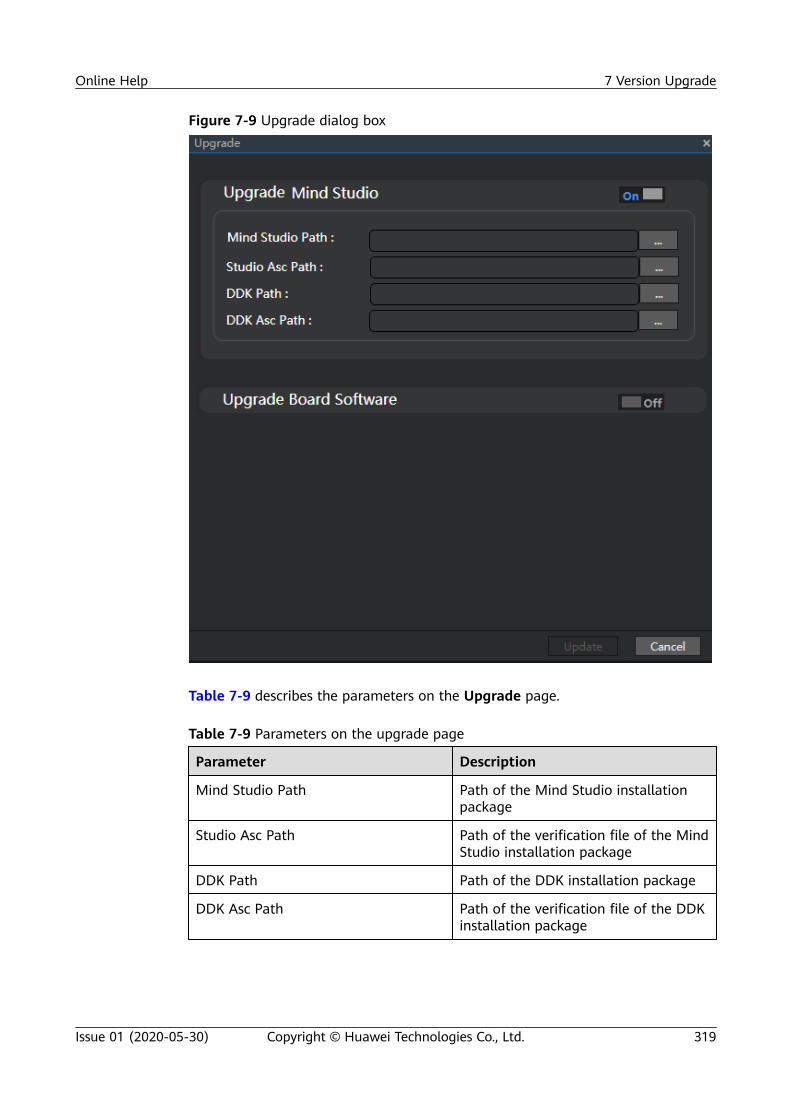
Figure 7-9 Upgrade dialog box
Table 7-9 describes the parameters on the Upgrade page.
Table 7-9 Parameters on the upgrade page
Parameter Description
Mind Studio Path Path of the Mind Studio installationpackage
Studio Asc Path Path of the verification file of the MindStudio installation package
DDK Path Path of the DDK installation package
DDK Asc Path Path of the verification file of the DDKinstallation package
Online Help 7 Version Upgrade
Issue 01 (2020-05-30) Copyright © Huawei Technologies Co., Ltd. 319

Step 2 Click next to Mind Studio Path, Studio Asc Path, DDK Path, and DDK AscPath, select the upgrade packages and the .asc files with the same name as theupgrade packages, and click Update to upload the files, as shown in Figure 7-10.
Figure 7-10 Uploading the upgrade packages and verification files
Step 3 After successful upload and verification, the dialog box as shown in Figure 7-11 isdisplayed. Click OK and the upgrade window is displayed. During the upgrade, theback-end services are disconnected and the front end is masked. In this phase, donot refresh or close the window.
Figure 7-11 Message displayed after the package is uploaded and verified
Online Help 7 Version Upgrade
Issue 01 (2020-05-30) Copyright © Huawei Technologies Co., Ltd. 320

Step 4 After the upgrade is successful, Mind Studio is restarted. The Mind Studio loginpage is displayed, as shown in Figure 7-12.
Figure 7-12 Upgrade success dialog box
----End
After the upgrade is successful or the upgrade is canceled, close the dialog box shown inFigure 7-10. The following redundant folders generated by the Mind Studio server will beautomatically deleted:
upgrade folder and upgradeForLog folder
Verifying the Upgrade
After the upgrade is successful, check whether the Mind Studio version is correctby referring to Querying Mind Studio Version in Ascend 310 Mind StudioInstallation Guide (CentOS, x86).
7.2.3 Exception HandlingIf an exception occurs during the upgrade, an error message is displayed in theupgrade dialog box. You can view the exception information in the ~/upgradeLogForMindStudio directory of the server. The following log files areprovided for the upgrade process.
Table 7-10 Upgrade log files
Log File Description
stopMindStudio.log Records the logs generated during the stop ofMind Studio.
Online Help 7 Version Upgrade
Issue 01 (2020-05-30) Copyright © Huawei Technologies Co., Ltd. 321

Log File Description
upgradeMindStudio.log Records information about uninstalling MindStudio of an earlier version, saving user data,installing Mind Studio of a later version, restoringuser data, and installing the DDK.
startMindStudio.log Records the logs generated during the startup ofMind Studio.
startNewIDE.log Records the information about the startup of MindStudio of a later version after successful upgrade.If the upgrade fails, the log file is not generated.
restartStudio.log Records the information about the startup of MindStudio of an earlier version after an upgradefailure. If the upgrade is successful, the log file isnot generated.
● If the message "Unpacking package failed" is displayed during the upgrade,check whether the upgradeassembly folder exists in the /tmp directory. Ifyes, delete the folder and try again.
● If the message "Please manually delete upgrade folder" is displayed duringthe upgrade, delete the ~/upgrade folder from the server and try again.
● If only stopMindStudio.log exists during the upgrade, check the log content,rectify the fault, restart Mind Studio, and perform the upgrade again.
● If only upgradeMindStudio.log exists but startMindStudio.log does not, runthe bash mind_studio.sh rollback command in the ~/upgrade/scriptsdirectory to roll back to an earlier version, restart the system, and perform theupgrade again.
● If only startMindStudio.log exists, restart Mind Studio in the installationdirectory to complete the upgrade.
7.3 CentOS ARM OSOnline upgrade of Mind Studio is supported. You do not need to uninstall MindStudio and reinstall it. You can directly upgrade it in the upgrade window.
Before the upgrade, query the current version of Mind Studio by referring to"Querying the Mind Studio Version" in the Ascend 310 Mind Studio InstallationGuide (CentOS, Arm).
● If the current version is 1.3.XX, upgrade it by referring to Table 7-11.● If the current version is 1.1.XX and you want to upgrade it to 1.3.X, refer to
Table 7-12.
Online Help 7 Version Upgrade
Issue 01 (2020-05-30) Copyright © Huawei Technologies Co., Ltd. 322

Table 7-11 1.3.XX upgrade
Source Version Target Version
1.3.T10.B770 to1.3.T21.B880
Upgrade to 1.3.T10.B770 to 1.3.T21.B880
1.3.T21.B880 to1.3.T25.B883
Online upgrade not supported
1.3.T25.B883,1.3.T26.B885, and later
Upgrade to 1.3.T28.B886 and later. However, you needto re-obtain the Mind Studio public keys. For details,see Configuring OpenPGP Public Keys in theinstallation guide of the target version.
Table 7-12 Upgrade from 1.1.XX to 1.3.XX
Source Version Target Version
Versions earlier than1.1.T8.B750
Online upgrade not supported. Performuninstallation then re-installation.
1.1.T8.B750 to1.1.T19.B880
Upgrade to 1.3.T10.B770 to 1.3.T21.B880
1.1.T19.B880 to1.1.T22.B883
Upgrade to 1.3.T22.B881, 1.3.T23.B882, or1.3.T25.B883 not supported
1.1.T22.B883,1.1.T23.B885, and later
Upgrade to 1.3.T28.B886 and later. However, youneed to re-obtain the Mind Studio public key. Fordetails, see Configuring OpenPGP Public Keys inthe installation guide of the target version.
XX indicates the version number.
7.3.1 Preparing for Upgrade● Ensure that the havaged dependency has been installed on the server where
Mind Studio is installed. Otherwise, run the sudo -E yum install havegedcommand on the server.
● Before the upgrade, run the gpg --list-keys command to check the public keyfiles in the system. If the following two public keys are returned, the upgradecan be performed. If only one of them is returned, obtain the missing one byreferring to Configuring OpenPGP Public Keys in Ascend 310 Mind StudioInstallation Guide (CentOS, Arm) before the upgrade.
Figure 7-13 Checking the public keys in the system
Online Help 7 Version Upgrade
Issue 01 (2020-05-30) Copyright © Huawei Technologies Co., Ltd. 323

● Before the upgrade, prepare the following installation packages.
Table 7-13 Overview of the software packages
Installation Package IntegrityVerification File
Application Scenario
mini_mind_studio_centos_arm_server.rar
mini_mind_studio_centos_arm_server.rar.asc
Mind Studio installationpackage for CentOS (Arm)
MSpore_DDK-{version}-aarch64.centOS7.6-aarch64.centOS7.6-aarch64.miniOS.tar.gz
MSpore_DDK-{version}-aarch64.centOS7.6-aarch64.centOS7.6-aarch64.miniOS.tar.gz.asc
DDK installation packagefor CentOS (Arm)
To verify software package integrity, you need to install the GnuPG tool and configurethe OpenPGP public keys on the Linux server where Mind Studio is installed. Fordetails, see Configuring OpenPGP Public Keys in Ascend 310 Mind Studio InstallationGuide (CentOS, Arm).
7.3.2 Performing Upgrade
PrerequisitesBefore the upgrade, log in to the server as the Mind Studio installation user,switch to the root user, and run the ./add_sudo.sh username script inthe /usr/bin directory to add permissions to the user. The command is as follows:
su root./add_sudo.sh username
Procedure
Step 1 Choose Help > Upgrade. The Upgrade dialog box is displayed, as shown in Figure7-14.
Online Help 7 Version Upgrade
Issue 01 (2020-05-30) Copyright © Huawei Technologies Co., Ltd. 324

Figure 7-14 Upgrade dialog box
Table 7-14 describes the parameters on the Upgrade page.
Table 7-14 Parameters on the upgrade page
Parameter Description
Mind Studio Path Path of the Mind Studio installationpackage
Studio Asc Path Path of the verification file of the MindStudio installation package
DDK Path Path of the DDK installation package
DDK Asc Path Path of the verification file of the DDKinstallation package
Online Help 7 Version Upgrade
Issue 01 (2020-05-30) Copyright © Huawei Technologies Co., Ltd. 325

Step 2 Click next to Mind Studio Path, Studio Asc Path, DDK Path, and DDK AscPath, select the upgrade packages and the .asc files with the same name as theupgrade packages, and click Update to upload the files, as shown in Figure 7-15.
Figure 7-15 Uploading the upgrade packages and verification files
Step 3 After successful upload and verification, the dialog box as shown in Figure 7-16 isdisplayed. Click OK and the upgrade window is displayed. During the upgrade, theback-end services are disconnected and the front end is masked. In this phase, donot refresh or close the window.
Figure 7-16 Message displayed after the package is uploaded and verified
Online Help 7 Version Upgrade
Issue 01 (2020-05-30) Copyright © Huawei Technologies Co., Ltd. 326

Step 4 After the upgrade is successful, Mind Studio is restarted. The Mind Studio loginpage is displayed, as shown in Figure 7-17.
Figure 7-17 Upgrade success dialog box
----End
After the upgrade is successful or the upgrade is canceled, close the dialog box shown inFigure 7-15. The following redundant folders generated by the Mind Studio server will beautomatically deleted:
upgrade folder and upgradeForLog folder
Verifying the Upgrade
After the upgrade is successful, check whether the Mind Studio version is correctby referring to Querying Mind Studio Version in Ascend 310 Mind StudioInstallation Guide (CentOS, x86).
7.3.3 Exception HandlingIf an exception occurs during the upgrade, an error message is displayed in theupgrade dialog box. You can view the exception information in the ~/upgradeLogForMindStudio directory of the server. The following log files areprovided for the upgrade process.
Table 7-15 Upgrade log files
Log File Description
stopMindStudio.log Records the logs generated during the stop ofMind Studio.
Online Help 7 Version Upgrade
Issue 01 (2020-05-30) Copyright © Huawei Technologies Co., Ltd. 327

Log File Description
upgradeMindStudio.log Records information about uninstalling MindStudio of an earlier version, saving user data,installing Mind Studio of a later version, restoringuser data, and installing the DDK.
startMindStudio.log Records the logs generated during the startup ofMind Studio.
startNewIDE.log Records the information about the startup of MindStudio of a later version after successful upgrade.If the upgrade fails, the log file is not generated.
restartStudio.log Records the information about the startup of MindStudio of an earlier version after an upgradefailure. If the upgrade is successful, the log file isnot generated.
● If the message "Unpacking package failed" is displayed during the upgrade,check whether the upgradeassembly folder exists in the /tmp directory. Ifyes, delete the folder and try again.
● If the message "Please manually delete upgrade folder" is displayed duringthe upgrade, delete the ~/upgrade folder from the server and try again.
● If only stopMindStudio.log exists during the upgrade, check the log content,rectify the fault, restart Mind Studio, and perform the upgrade again.
● If only upgradeMindStudio.log exists but startMindStudio.log does not, runthe bash mind_studio.sh rollback command in the ~/upgrade/scriptsdirectory to roll back to an earlier version, restart the system, and perform theupgrade again.
● If only startMindStudio.log exists, restart Mind Studio in the installationdirectory to complete the upgrade.
Online Help 7 Version Upgrade
Issue 01 (2020-05-30) Copyright © Huawei Technologies Co., Ltd. 328

A Change History
Release Date Description
2020-05-30 This issue is the first official release.
Online Help A Change History
Issue 01 (2020-05-30) Copyright © Huawei Technologies Co., Ltd. 329