On-board Handbook Expedition Participants Research Vessel ...
222
17/01/2018 2017_FS-Meteor_EN-2-1-2 1 - 1 On-board Handbook for Expedition Participants 2017_FS-Meteor_DE-2-1-2.docx Research Vessel METEOR Research Vessel METEOR
-
Upload
khangminh22 -
Category
Documents
-
view
4 -
download
0
Transcript of On-board Handbook Expedition Participants Research Vessel ...

17/01/2018 2017_FS-Meteor_EN-2-1-2 1 - 1
On-board Handbook for
Expedition Participants
2017_FS-Meteor_DE-2-1-2.docx
Research Vessel METEOR
Research Vessel METEOR

17/01/2018 2 - 1 2017_FS-Meteor_EN-2-1-2
Table of revisions:
Version Subject of the change Processor Date
Origin Meteor Handbook Crew and inspection RF Reederei Forschungsschifffahrt
V 1.0 New document Dr. Rogenhagen / Crew and inspection Reederei F. Laeisz (Bremerhaven) GmbH
IV/2011
V 1.1 Various updates Dr. Rogenhagen / Crew and inspection Reederei F. Laeisz (Bremerhaven) GmbH
XI/2012
V 2.0 Various updates Klaus Bergmann Briese Schiffahrts GmbH&Co. KG Research Shipping Department
IV/2013
V 2.1 Various updates Klaus Bergmann Briese Schiffahrts GmbH&Co. KG Research Shipping Department
V/2014
V 2.1.1 Various updates Klaus Bergmann Briese Schiffahrts GmbH&Co. KG Research Shipping Department
IX/2015
V 2.1.2 Various updates Klaus Bergmann Briese Schiffahrts GmbH&Co. KG Research Shipping Department
VII/2017

17/01/2018 2017_FS-Meteor_EN-2-1-2 3 - 1
Table of contents
1. Research vessel Meteor ................................................................................. 1-9
1.1 Technical Data ................................................................................................ 1-10
1.1.1 Ship ................................................................................................................ 1-10
1.1.2 Machinery ....................................................................................................... 1-11
1.1.3 Energy generation .......................................................................................... 1-11
1.1.4 Aids to manoeuvring ....................................................................................... 1-11
2. Crew .............................................................................................................. 2-12
3. Plans of the ship ........................................................................................... 3-13
3.1 Deck arrangement .......................................................................................... 3-14
3.2 Deck plans ...................................................................................................... 3-16
3.2.1 6th and 5th superstructure deck...................................................................... 3-16
3.2.2 4th and 3rd superstructure deck ..................................................................... 3-18
3.2.3 2nd superstructure deck ................................................................................. 3-20
3.2.4 1st superstructure deck .................................................................................. 3-22
3.2.5 Forecastle deck .............................................................................................. 3-24
3.2.6 Main deck ....................................................................................................... 3-26
3.2.7 Tween deck .................................................................................................... 3-28
3.2.8 Storage ........................................................................................................... 3-30
3.2.9 Raised floor .................................................................................................... 3-32
3.3 Plan of staircases ........................................................................................... 3-34
3.4 Lifting apparatus with working area ................................................................. 3-36
3.4.1 Cranes on the working deck ........................................................................... 3-36
3.4.2 Outrigger ........................................................................................................ 3-38
3.4.3 Movebar ......................................................................................................... 3-40
3.4.4 Rear gallows ................................................................................................... 3-42
3.4.5 Crane on the foredeck .................................................................................... 3-44
3.4.6 Crane on 5th superstructure deck ................................................................... 3-46
3.5 Winch and rope data ....................................................................................... 3-48
3.6 Container spaces ............................................................................................ 3-50
3.6.1 Numbering of container spaces ...................................................................... 3-52
3.6.2 Deck socket grid ............................................................................................. 3-54
3.7 Scientific storage area .................................................................................... 3-56
3.7.1 Scientific storage areas I and IV ..................................................................... 3-56
3.7.2 Scientific storage areas II and III ..................................................................... 3-58
3.8 Antenna plans ................................................................................................. 3-60
3.8.1 Communication antennae ............................................................................... 3-60

17/01/2018 4 - 1 2017_FS-Meteor_EN-2-1-2
3.8.2 Navigation antennae ....................................................................................... 3-62
3.8.3 Antennae and sensors used for meteorological purposes ............................... 3-64
3.9 Overview: Escape routes / assembly point / rescue resources ........................ 3-66
4. Laboratory and workrooms on board.......................................................... 4-68
4.1 General ........................................................................................................... 4-68
4.1.1 Laboratory sockets: ........................................................................................ 4-69
4.1.2 Securing of heavy objects ............................................................................... 4-69
4.1.3 Securing of light objects to walls ..................................................................... 4-69
4.2 Air chemistry laboratory 1 ............................................................................... 4-70
4.3 Sounding centre 2 ........................................................................................... 4-74
4.4 Darkroom 3 ..................................................................................................... 4-76
4.5 Clean laboratory 4 with double door ................................................................ 4-78
4.6 Clean laboratory 5 .......................................................................................... 4-82
4.7 Bio-chemistry laboratory 6 .............................................................................. 4-86
4.8 Dry laboratory 7 .............................................................................................. 4-90
4.9 Dry laboratory 8 .............................................................................................. 4-94
4.10 Measurement and registration room 9 ............................................................ 4-98
4.11 Wet laboratory 10 ......................................................................................... 4-102
4.12 Air gun room 11 ............................................................................................ 4-106
4.13 Gravimeter room 12 ...................................................................................... 4-108
4.14 Drawing room 13 .......................................................................................... 4-110
4.15 Universal laboratory 15 ................................................................................. 4-114
4.16 Geo laboratory 16 ......................................................................................... 4-118
4.17 Filling room 17 .............................................................................................. 4-122
4.18 Measurement and sounding room 18 ............................................................ 4-126
4.19 Air conditioned laboratory unit 19 .................................................................. 4-128
4.20 Bridge ........................................................................................................... 4-132
4.21 German Meteorological Service (DWD) ........................................................ 4-134
4.21.1 Tasks of the on board weather service ......................................................... 4-135
4.21.2 Meteorological Advice ................................................................................... 4-135
4.21.3 Data recording .............................................................................................. 4-137
4.21.4 Trajectory data .............................................................................................. 4-137
4.22 Conference room .......................................................................................... 4-138
4.23 Library .......................................................................................................... 4-140
5. Appliances and equipment ........................................................................ 5-142
5.1 Hydro acoustic equipment and measurement appliances ............................. 5-142

17/01/2018 2017_FS-Meteor_EN-2-1-2 5 - 1
5.1.1 Echo sounder for bathymetric measurement................................................. 5-143
5.1.2 Echo sounder for bathymetric deep sea measurement ................................. 5-144
5.1.3 Deep sea sediment echo sounder ................................................................ 5-148
5.1.4 Navigation echo sounder / echograph .......................................................... 5-152
5.1.5 Acoustic Doppler current profiler ................................................................... 5-154
5.1.6 Position sensor ............................................................................................. 5-156
5.1.7 Seapath ........................................................................................................ 5-158
5.1.8 2-axis Doppler log ......................................................................................... 5-160
5.2 Other navigation and measurement appliances ............................................ 5-162
5.2.1 Underwater positioning system ..................................................................... 5-162
5.2.2 Differential GPS (DGPS) .............................................................................. 5-164
5.2.3 Global Positioning System (GPS) ................................................................. 5-165
5.2.4 VHF radio direction finder ............................................................................. 5-166
5.2.5 GPS position sensor ..................................................................................... 5-168
5.2.6 Gyrocompass ............................................................................................... 5-169
5.2.7 Fibre optic course and position reference system FOG ................................ 5-170
5.3 Scientific work equipment ............................................................................. 5-172
5.3.1 Hydrophone extension unit ........................................................................... 5-172
5.3.2 Deep freezers ............................................................................................... 5-173
5.3.3 Thermosalinograph ....................................................................................... 5-174
5.3.4 Sounding shaft .............................................................................................. 5-177
5.3.5 Water-borne sound detectors ....................................................................... 5-178
5.3.6 Core stacking frame ...................................................................................... 5-179
5.3.7 CTD probe and water carousel ..................................................................... 5-181
5.3.8 Radiation protection container ...................................................................... 5-183
5.3.9 MeBo launching device ................................................................................. 5-187
5.3.10 Nitrogen generator ........................................................................................ 5-189
5.3.11 Milli-Q Integral 10 ultra-pure water system .................................................... 5-191
5.3.12 Container cable winch .................................................................................. 5-193
5.4 Working boats ............................................................................................... 5-197
5.4.1 Motor rescue and working boat METEORIT .................................................... 5-198
5.4.2 Working boat ................................................................................................ 5-199
6. Communication .......................................................................................... 6-201
6.1 Marine radio ................................................................................................. 6-201
6.2 Telephone/fax/data ....................................................................................... 6-201
6.2.1 Dedicated line (C band / KU band) ............................................................... 6-201
6.2.2 Iridium OpenPort .......................................................................................... 6-201
6.2.3 RV Meteor telephone numbers ..................................................................... 6-202
6.2.4 Telephone (private use) ................................................................................ 6-202

17/01/2018 6 - 1 2017_FS-Meteor_EN-2-1-2
6.2.5 On board telephone ...................................................................................... 6-202
6.3 Scientific intercom system ............................................................................ 6-203
6.4 E-mail ........................................................................................................... 6-203
6.4.1 Personal e-mail address ............................................................................... 6-203
6.4.2 Permanent e-mail addresses ........................................................................ 6-203
6.4.3 Accessibility of the ship ................................................................................. 6-204
6.5 Internet ......................................................................................................... 6-204
6.5.1 PC with internet access ................................................................................ 6-204
6.5.2 Internet use, bandwidth ................................................................................. 6-204
6.6 Network (LAN) .............................................................................................. 6-205
6.6.1 Description .................................................................................................... 6-205
6.6.2 Rooms with network connections (LAN) ....................................................... 6-205
6.7 PC work stations ........................................................................................... 6-207
6.7.1 Scientific PC work stations ............................................................................ 6-207
6.7.2 Software ....................................................................................................... 6-207
6.8 DSHIP display PC ......................................................................................... 6-208
6.8.1 Recording of data ......................................................................................... 6-208
6.8.2 Distribution of data ........................................................................................ 6-208
6.8.3 Visualisation of data ...................................................................................... 6-208
6.8.4 Storage of data ............................................................................................. 6-208
6.8.5 Export of data ............................................................................................... 6-210
6.8.6 Further features ............................................................................................ 6-210
6.9 Camera monitoring system ........................................................................... 6-211
6.9.1 Description .................................................................................................... 6-212
6.9.2 Cameras on RV Meteor ................................................................................ 6-212
7. Life on board ............................................................................................... 7-213
7.1 Cabins .......................................................................................................... 7-214
7.2 Food ............................................................................................................. 7-216
7.3 Sale of canteen goods .................................................................................. 7-216
7.4 On board laundry .......................................................................................... 7-216
7.5 General rules of conduct ............................................................................... 7-216
7.5.1 Safety ........................................................................................................... 7-216
7.5.2 Health ........................................................................................................... 7-217
7.5.3 Battery supply ............................................................................................... 7-217
7.5.4 Glasses ........................................................................................................ 7-217
7.5.5 Table tennis .................................................................................................. 7-217
7.5.6 Room doors .................................................................................................. 7-217
7.6 Waste disposal ............................................................................................. 7-217

17/01/2018 2017_FS-Meteor_EN-2-1-2 7 - 1
7.6.1 Waste separation .......................................................................................... 7-217
7.6.2 Packaging ..................................................................................................... 7-217
7.6.3 Used batteries .............................................................................................. 7-218
7.6.4 Residual waste ............................................................................................. 7-218
7.6.5 Chemicals ..................................................................................................... 7-219

17/01/2018 8 - 1 2017_FS-Meteor_EN-2-1-2
Index
“Neptune” Postprocessing Software . 5-147 A0 plotter ......................................... 4-110 ADCP ............................................... 5-155 ADU-2 .............................................. 5-169 Air pulse fittings ............................... 4-106 Applied Microsystems SV Plus V2 ... 5-178 Bathymetric measurement ............... 5-143 Cashless payment ........................... 7-216 C-bars ................................................ 4-69 Cold room ........................................ 4-129 Computer network ............................ 6-205 CTD deck unit .................................... 4-99 CTD water carousel ......................... 4-123 Data transfer .................................... 6-207 Disembark........................................ 7-216 ELAC LAZ 5100 ............................... 5-153 Emergency shower ............................ 4-83 Fitness room .................................... 7-215 Fume cupboard ......................... 4-87, 4-91 General alarm .................................. 7-216 Gonio ............................................... 5-167 Gonio radio direction finder ................ 4-71 GPS C-Nav ...................................... 5-165 GPS position sensor ADU 2 ............... 4-71 Gravimeter base .............................. 4-108 Headquarters ....................................... 1-9 Hydrophone ..................................... 4-121 Icon .................................................... 4-69 Inflatable boat .................................. 5-199 IXSEA TT-801 .................................. 5-172 Junction box winches W 2,3,12 ........ 4-115 Kongsberg EM 122 1° x 2° .............. 5-145 Kongsberg EM 710 1° x 1° ............... 5-143 Laboratory and measuring room ...... 4-129 Laboratory cleaning machine ............. 4-95 Laboratory network ............................ 4-69
Measurement data distributors ......... 4-117 MeBo ................................................ 5-187 Mess ................................................ 7-213 Meteorit ............................................ 5-197 Milli-Q Integral 10 ............................. 5-192 Navigat X MK1 ................................. 5-169 Network connection standard ........... 6-207 Network printer / scanner ................. 4-110 Parasound DS-3 / P70 ...................... 5-149 Parastore-3 Post processing system .............................................. 5-151 Posidonia 6000 ........................ 4-98, 5-163 Position sensor MRU 5 ..................... 5-157 Pre-paid card .................................... 6-202 Projector ........................................... 4-139 RhoTheta 300 ................................... 5-167 SAM 4683 Doppler log ..................... 5-161 SBE21 Seacat .................................. 5-176 Scientific journey planning .................... 1-9 Sea forecast ..................................... 4-135 Seacat .............................................. 4-121 Seapath 300 ..................................... 5-159 Senate Commission for Oceanography ...................................... 1-9 Shipowner ............................................ 1-9 Sounding shaft ................................. 4-122 Sounding shaft basket ...................... 4-123 Sports equipment ............................. 7-215 Standard operating system ............... 6-207 Telephone box .................................. 6-202 Thermometer SBE38 ........................ 5-176 Thermosalinograph................ 4-127, 5-174 Transducer ITC–3013 ....................... 5-172 Weather forecast .............................. 4-135 Wet work table .................................. 4-103 Winch control station ........................ 4-132
17/01/2018 2017_FS-Meteor_EN-2-1-2 9 - 1
1. RESEARCH VESSEL METEOR Information about the ship
Ship's name: Meteor
Call sign: DBBH
IMO number: 8411279
Flag: German flag (federal service flag)
Home port: Hamburg
Owner: Federal Republic of Germany, represented by the BMBF (Federal Ministry for Education and Research)
Scientific journey planning: Senate Commission for Oceanography
Chair Prof. Dr. Michael Schulz
MARUM – Centre for Marine Sciences
University of Bremen
Leobener Straße
28359 Bremen
Logistics/supervision of ship's operation:
Headquarters German research vessels
Institute for Geology of the University of Hamburg
Prof. Dr. Christian Betzler
Bundesstraße 55
20146 Hamburg
Tel: (040) 42838-3640
Fax: (040) 42838-4644
E-Mail: [email protected]
Homepage: http://www.ifm.zmaw.de/de/leitstelle
Shipowner Briese Schiffahrts GmbH & Co.KG
Research Shipping Department
Hafenstraße 12
D-26789 Leer, Germany
Phone: +49 (0) 491 925 20 – 160
Fax: +49 (0) 491 925 20 – 169
www.briese.de

17/01/2018 10 - 1 2017_FS-Meteor_EN-2-1-2
1.1 Technical Data
1.1.1 Ship Ship's data
Shipyard Schlichting-Werft, Travemünde
Year of manufacture 1985/86
Build number 2030
Class GL+100 A5 E2+MC AUT
Certified according to DIN EN ISO 9002 + ISM-Code
Total length 97.50 m
Length between perpendiculars
90.00 m
Width 16.50 m
Depth 5.61 m
Height of main deck 7.70 m
Total height 46.40 m
Loop antenna folded down 45.00 m
Measurement according to London agreement
4.280 BRZ
Unladen weight of ship 3,825 t
Scientific load capacity plus 40 t for fixed load capacity, spare wires etc.
100 t
60 t
Speed 11.5 kn
Sphere of action (at 11.5 kn) 10,000 NM
Crew 33
Scientists / technicians 28
German Meteorological Service (DWD)
2

17/01/2018 2017_FS-Meteor_EN-2-1-2 11 - 1
1.1.2 Machinery
2 electrical propulsion motors 1,150 kW each
1 fixed pitch propeller 5 blades, diameter 3.00 m
1.1.3 Energy generation
4 diesel engines Each 1,000 kW at 750 rpm
4 alternating current generators Each 1,350 kVA at 660 V
1 port diesel 342 kW at 1,500 rpm
1 alternating current generator 390 kVA at 380 V
1 emergency diesel 81.9 kW at 1,500 rpm
1 alternating current generator 93 kVA at 380 V
1.1.4 Aids to manoeuvring
Bow thruster, extendable HRP 6011 PT with 1,100 kW, max. 1,200 rpm
Fin stabilisers HDW 2 x 5.1 m²
Rudder Spade rudder with hinged fin

17/01/2018 12 - 2 2017_FS-Meteor_EN-2-1-2
2. CREW
Function Number
Master 1
Leading nautical officer 1
1st Officer 1
2nd Officer 1
1st Engineer 1
2nd Engineer 2
Electrical engineer 1
Leader of the Scientific Technical Service (WTD) 1
WTD electronic engineer 1
WTD systems engineer 1
Doctor 1
Cook 1
Assistant cook 1
Fitter 1
Bosun 1
1st Steward 1
2nd Steward 2
Machine room mechanic 3
Deck mechanic 7
Launderer 1
Trainee max. 3
Total 30 – 33

17/01/2018 2017_FS-Meteor_EN-2-1-2 3 - 13
3. PLANS OF THE SHIP
Fig. 1 Research vessel METEOR

17/01/2018 14 -3 2017_FS-Meteor_EN-2-1-2
3.1 Deck arrangement
1
2
3
4
5
6
7
8
9
10
11
21 20 19 18 17 16 15 14 13 12
Fig. 2 RV METEOR, deck arrangement, scientific storage space, propulsion and aids to manoeuvring

17/01/2018 2017_FS-Meteor_EN-2-1-2 3 - 15
Key:
1 6th superstructure deck 2 5th superstructure deck 3 4th superstructure deck, bridge 4 3rd superstructure deck (dark green doors) 5 2nd superstructure deck (green doors) 6 1st superstructure deck (yellow doors) 7 Forecastle deck (orange doors) 8 Main deck (red doors) 9 Tween deck (dark red doors) 10 Storage 11 Raised floor 12 Scientific storage area I 13 Bow thruster 14 Fin stabilisers 15 Energy generation 16 Scientific storage area IV 17 Scientific storage area II 18 Drive motors 19 Scientific storage area III 20 Propeller 21 Spade rudder (Becker rudder with fin)

17/01/2018 16 -3 2017_FS-Meteor_EN-2-1-2
3.2 Deck plans
3.2.1 6th and 5th superstructure deck
1 2 3 4
1 2 6 5
Fig. 3 RV METEOR, 6th and 5th superstructure deck

17/01/2018 2017_FS-Meteor_EN-2-1-2 3 - 17
Key:
1 Centre line 2 Outer edge of main deck / bulwark 3 Antenna and signal mast 4 Work surface 6th superstructure deck 5 Air chemistry laboratory 6 Gas bottle area

17/01/2018 18 -3 2017_FS-Meteor_EN-2-1-2
3.2.2 4th and 3rd superstructure deck
1 2 3 4 5 6 7
1 2 12 11 10 9 8
Fig. 4 RV METEOR, 4th and 3rd superstructure deck

17/01/2018 2017_FS-Meteor_EN-2-1-2 3 - 19
Key:
1 Centre line 2 Outer edge of main deck / bulwark 3 Rear control console 4 Scientific workplace 5 Raised deck 6 Bridge wings 7 Main control console 8 Converter room 9 Side room 10 Telephone box 11 Radio room 12 Sounding centre

17/01/2018 20 -3 2017_FS-Meteor_EN-2-1-2
3.2.3 2nd superstructure deck
1 2 3 4 5 6 420* 8 9 10 11
433 14 13 12
Fig. 5 RV METEOR, 2nd superstructure deck

17/01/2018 2017_FS-Meteor_EN-2-1-2 3 - 21
Key:
1 Centre line 2 Outer edge of main deck / bulwark 3 Paint store 4 Room: Crew (work experience person) 5 On board weather station 6 Ship's office 420 Room: Weather technician 8 Room: Scientific Head of WTD 9 Room: 1st Officer 10 Room: Chief engineer 11 Helicopter abseil deck 12 Room: Master 13 Room: 2nd Officer 14 Room: 2nd Officer 433* Room: Scientific expedition leader *: Position number = room number scientific expedition participants

17/01/2018 22 -3 2017_FS-Meteor_EN-2-1-2
3.2.4 1st superstructure deck
1 2 3 4 552* 6 7 8 9 10 11 12 13 14 15
16
29 28 27 26 25 543* 539* 535* 529* 525* 519* 511* 505*
Fig. 6 RV METEOR, 1st superstructure deck

17/01/2018 2017_FS-Meteor_EN-2-1-2 3 - 23
Key:
1 Centre line 2 Outer edge of main deck / bulwark 3 Winch electronics room 4 Workboat / lifeboat METEORIT 552* Room: Meteorologist 6 Room: 1st Cook 7 Room: 1st Steward 8 Room: Fitter 9 Room: 1st Bosun 10 Room: Electronic engineer 11 Room: System Manager 12 Room: Electrician 13 Room: 2nd Engineer 14 Room: 2nd Engineer 15 Office: Machine 16 Dark room 505* Room: 1 scientist + 1 reserve 511* Room: 1 scientist + 1 reserve 519* Room: 1 scientist + 1 reserve 525* Room: 1 scientist + 1 reserve 529* Room: 1 scientist + 1 reserve 535* Room: 1 scientist + 1 reserve 539* Room: 1 scientist + 1 reserve 543* Room: Senior scientist 25 Free time area 26 Sauna 27 Lifeboat 28 Emergency diesel room 29 Movebar *: Position number = room number

17/01/2018 24 -3 2017_FS-Meteor_EN-2-1-2
3.2.5 Forecastle deck
1 2 3 4 5 6 7 8 9 10 11 12 13 14 15 16 17 18 19
20
21
22
33 32 31 30 29 28 27 26 25 24 23
Fig. 7 RV METEOR, forecastle deck
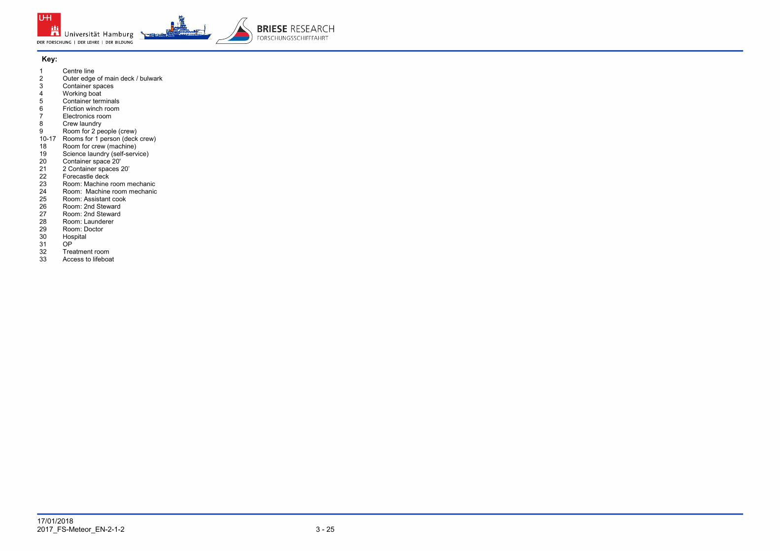
17/01/2018 2017_FS-Meteor_EN-2-1-2 3 - 25
Key:
1 Centre line 2 Outer edge of main deck / bulwark 3 Container spaces 4 Working boat 5 Container terminals 6 Friction winch room 7 Electronics room 8 Crew laundry 9 Room for 2 people (crew) 10-17 Rooms for 1 person (deck crew) 18 Room for crew (machine) 19 Science laundry (self-service) 20 Container space 20' 21 2 Container spaces 20’ 22 Forecastle deck 23 Room: Machine room mechanic 24 Room: Machine room mechanic 25 Room: Assistant cook 26 Room: 2nd Steward 27 Room: 2nd Steward 28 Room: Launderer 29 Room: Doctor 30 Hospital 31 OP 32 Treatment room 33 Access to lifeboat

17/01/2018 26 -3 2017_FS-Meteor_EN-2-1-2
3.2.6 Main deck
1 2 3 4 5 6 7 8 9 10 11 12 13 14 742* 736* 734* 726* 724* 718* 15 16
27 26 25 24 23 22 21 20 19 18 17
Fig. 8 RV METEOR, main deck with scientific working areas and living areas

17/01/2018 2017_FS-Meteor_EN-2-1-2 3 - 27
Key:
1 Centre line 2 Outer edge of main deck / bulwark 3 Container terminals 4 Pulser station (laboratory 11) 5 Deck workshop 6 Wet laboratory (laboratory 10)2 7 Measurement and registration room (laboratory 9) 8 Electronics workshop 9 Dry laboratory (laboratory 8) 10 Dry laboratory (laboratory 7) 11 Chemistry and biology laboratory (laboratory 6) 12 Clean laboratory (laboratory 5) 13 Clean laboratory (laboratory 4) 14 Double doors to clean laboratory 742* Room: 1 scientist + 1 reserve 736* Room: 1 scientist + 1 reserve 734* Room: 1 scientist + 1 reserve 726* Room: 1 scientist + 1 reserve 724* Room: 1 scientist + 1 reserve 718* Room: 1 scientist + 1 reserve 15 Laundry 16 Scientific storage area I 17 Paper store 18 Library 19 Conference room 20 Drawing room (laboratory 13) 21 Computer room 22 Universal laboratory (laboratory 15) 23 Geology laboratory (laboratory 16) 24 Gravimeter room (laboratory 12) 25 Filling room (laboratory 17) 26 Store for hazardous materials 27 Lift *: Position number = room number
17/01/2018 28 -3 2017_FS-Meteor_EN-2-1-2
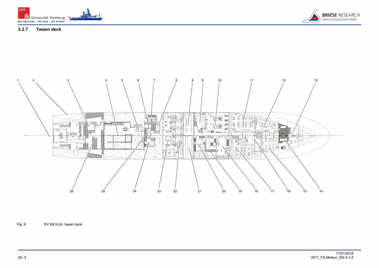
3.2.7 Tween deck
1 2 3 4 5 6 7 6 8 9 10 11 12 13
26 25 24 23 22 21 20 19 18 17 16 15 14
Fig. 9 RV METEOR, tween deck

17/01/2018 2017_FS-Meteor_EN-2-1-2 3 - 29
Key:
1 Centre line 2 Outer edge of main deck / bulwark 3 Chemicals room 4 Scientific storage area II 5 Lift 6 2 refrigeration rooms -2 to -25 °C 7 Storage winch W 12, 18.2 mm-single conductor cable 8 Machine control console 9 Waste incineration plant 10 Refrigeration room 11 Mess 1 for 28 people 12 Meeting room with bar 13 Measurement and sounding room 14 Bow thruster 15 Mess 2 for 16 people 16 Pantry 17 Galley 18 Machine workshop 19 Welding workshop 20 Electrical workshop 21 Control room 22 Machine room 23 Sounding shaft 24 Aquarium -2 to +25 °C 25 Laboratory and measuring room 26 Scientific storage area III
Tween deck

17/01/2018 30 -3 2017_FS-Meteor_EN-2-1-2
3.2.8 Storage
1 2 3 4 5 6 7 8 9
12 11 10
Fig. 10 RV METEOR, storage

17/01/2018 2017_FS-Meteor_EN-2-1-2 3 - 31
Key:
1 Centre line 2 Outer edge of main deck / bulwark 3 Drive motor room 4 Scientific storage area IV 5 Storage winch W 11, 18 mm-deep sea wire 6 Diesel generator room 7 Auxiliary engine room 8 Storage / refrigeration areas ship 9 Ground measurement room 10 Auxiliary engine room 11 Hydraulic room 12 Propeller
Storage

17/01/2018 32 -3 2017_FS-Meteor_EN-2-1-2
3.2.9 Raised floor
1 2 3 4 5 6 7 8 9 10 11
19 18 17 16 15 14 13 12
Fig. 11 RV METEOR, raised floor with sensors

17/01/2018 2017_FS-Meteor_EN-2-1-2 3 - 33
Key:
1 Centre line 2 Outer edge of main deck / bulwark 3 Transponder converter 4 Pinger converter 5 Hydraulic lowering device 6 Naviknot converter 7 75 kHz-converter ADCP 8 Dual frequency sound converter 9 Dual frequency sound converter 10 ATLAS Dolog converter 11 Pure sea water intake 12 Dual frequency sound converter 13 Transponder converter 14 Pure sea water intake 15 Bow thruster 16 Posidonia converter 17 EM 710 transmitting and receiving converter 18 EM 122 receiving converter 19 EM 122 transmitting converter

17/01/2018 34 -3 2017_FS-Meteor_EN-2-1-2
3.3 Plan of staircases
1 2 3 4 5 6 7 8 9 10 11 12
20 19 18 17 16 15 14 13
Fig. 12 RV METEOR, arrangement of connecting staircases inside the ship

17/01/2018 2017_FS-Meteor_EN-2-1-2 3 - 35
Key:
1 Deck companionway forecastle rear: Staircase to scientific storage room 3 2 Tween deck under “3”: Staircase to scientific storage room 4 3 Main deck next to measurement and registration room: Staircase to scientific storage room
2 4 Main deck outside: Staircase midships to the forecastle deck under the movebar 5 Movebar area 6 Inner main deck opposite WTD-workshop: Staircase to the air-conditioned laboratory
rooms 7 3rd superstructure deck: Staircase to the 4th superstructure deck (sounding centre to
bridge aft) 8 4th superstructure deck: Staircase to the 5th superstructure deck (air chemistry) 9 3rd superstructure deck: Staircase to the 4th superstructure deck (radio centre to bridge
front) 10 Central staircase: Main deck to 3rd superstructure deck, main deck to tween deck 11 Main deck: Staircase to mess (tween deck) and machine (storage) 12 Front staircase: Main deck 1st superstructure deck, main deck to the bar (tween deck) 13 Scientific storage area 1 (main deck) 14 Meeting room with bar / mess 2 (tween deck) 15 Mess 1 for scientists and officers (tween deck) 16 Machine rooms (storage and tween deck) 17 Air-conditioned laboratory rooms (tween deck) 18 Scientific storage area 2 (tween deck) 19 Scientific storage area 4 (storage) 20 Scientific storage area 3 (tween deck)

17/01/2018 36 -3 2017_FS-Meteor_EN-2-1-2
3.4 Lifting apparatus with working area
3.4.1 Cranes on the working deck 1
6
5 4 3 2
Fig. 13 RV METEOR, deck cranes and lifting apparatus with working area

17/01/2018 2017_FS-Meteor_EN-2-1-2 3 - 37
Key:
1 Crane port rear (9): SWL 2,000 kg at 13 m radius 2 Outrigger (3): SDL 3,000 kg with 5,83 m radius 3 Movebar (4): SWL 20,000 kg at 7.6 m radius 4 Crane deck centre (5): SWL 5,500 kg at 15.5 m radius 5 Crane starboard rear (6): SWL 5,500 kg at 15.5 m radius, identical in construction to
pos. 4 6 Rear gallows (7): SWL 20,000 kg up to 3 m behind transom

17/01/2018 38 -3 2017_FS-Meteor_EN-2-1-2
3.4.2 Outrigger
1 2 3 1 4 5
4, 5
8
7 6
Fig. 14 RV METEOR, outrigger with winch arrangement and cable guide
17/01/2018 2017_FS-Meteor_EN-2-1-2 3 - 39
Key:
1 Winch W 3 (installation height 1st superstructure deck) 2 Outrigger in upper end position 3 Outrigger in side end position 4 Winch W 2 (installation height forecastle) 5 Winch W 1 (dto.) 6 Winch console 7 Working deck (main deck) 8 Bulwark

17/01/2018 40 -3 2017_FS-Meteor_EN-2-1-2
3.4.3 Movebar
1 2 3 4 5 6 3
8 7 5
Fig. 15 RV METEOR, movebar
1: 150
3.15m 3.15m

17/01/2018 2017_FS-Meteor_EN-2-1-2 3 - 41
Key:
1 Friction winch W 10 2 Oceanographic wire winch W 4 3 Movebar and outriggers in stop position 4 Movebar in outer end position (Safe Design Load (SDL) 20 t) 5 Movebar positioning winch W 16 SDL 8 t 6 Movebar outrigger in outer working position SDL 7.5 t 7 Storage winch W 11 8 Storage winch W 12

17/01/2018 42 -3 2017_FS-Meteor_EN-2-1-2
3.4.4 Rear gallows
1 2 3
4
Fig. 16 RV METEOR, rear gallows
10 m
4 m
11 m
8 m
0 1 2
1: 150

17/01/2018 2017_FS-Meteor_EN-2-1-2 3 - 43
Key:
1 Rear gallows end position, swivelled out SDL 30 t 2 Winch W 14 SDL 10t 3 Rear gallows end position, swivelled in SDL 30 t 4 Hydraulic swing drive under working deck
Lifting apparatus

17/01/2018 44 -3 2017_FS-Meteor_EN-2-1-2
3.4.5 Crane on the foredeck
1
Fig. 17 RV METEOR, crane on the foredeck (provision crane)
SWL 8.000 kg

17/01/2018 2017_FS-Meteor_EN-2-1-2 3 - 45
Key:
1 Provision crane on the foreship: SWL 8,000 kg at 11 m radius
Lifting apparatus

17/01/2018 46 -3 2017_FS-Meteor_EN-2-1-2
3.4.6 Crane on 5th superstructure deck
1 2
Fig. 18 RV METEOR, crane on 5th superstructure deck
SWL 400 kg

17/01/2018 2017_FS-Meteor_EN-2-1-2 3 - 47
Key:
1 Position of crane on 5th superstructure deck, near rib 64
2 Crane on 5th superstructure deck SWL 400 kg at 5 m radius
Lifting apparatus

17/01/2018 48 -3 2017_FS-Meteor_EN-2-1-2
3.5 Winch and rope data Winch number / (position number) W 1 W 2 W 3 W 4 W 10 W 11 W 12 W 14 W 16 W 17
Winch type Single conductor and series winch Oceanographic wire winch
Friction winch Storage winch Storage winch Rear gallows winch, switchable Movebar positioning winch Transportable rewind winch
Heave speed [m/sec] 0 – 2 0 – 2 0 – 2 0 – 2 0 – 2 0 – 2 0 – 2 0 – 0.3 0 – 0.6 0 – 0.33 3 – 30 m/min
Rope number D 1 K 1 K 2 D 2
Rope type COSA aramide fibre rope
Single conductor
Single conductor cable
Stainless steel wire
Wire Single conductor cable
Drakoflex wire Single conductor cable
Casar Powerplast wire rope Casar Powerplast wire rope
Diameter [mm] 8 11 11 6 18 18 18.2 22 18 max 18.2
Length [m] 6000 6000 6000 2000 11000 8000, room for
11000 45 45
Make Aramide fibre core with PA inlay + PE sheath
Coax, steel-reinforced
Coax, steel-reinforced
1x19 1570 N/m² sZ
Drakoflex 1700A zZ
Coax, steel-reinforced Right-hand lay, Warrington Seale
36x6, right-hand lay, sZ, plastic core
Corrosion protection galvanised galvanised Stainless steel thick galvanised
thick galvanised
galvanised galvanised
Twist free condition non-rotating non-rotating non-rotating non-rotating
Tractive force of the winch [kN] 30 30 30 25 200 10/friction 200 10/friction 200 100 50 80 30
Breaking strength [kN] 36 80 80 29.7 207 175 471 300.1
Breaking strength single wires [kN] 1.6 1.6 1.77 1.8 1.96 1.96
Safe Working Load [kN], SF= 3.6 (GL for research) or 4 (manufacturer) 10 20 20 8.25 57.5 43.75 130.8 130.8 83.4
Empty weight [kg/km] 60 470 470 179 1260 1120 2518 1676
Weight in water [kg/km] 12 390 390 Approx. 160 956 850 2518 1776
Total weight in water [kg] 72 2340 2340 Approx. 320 10519 6800 113.3 79.92 Max. residual load in water against pull of winch [kg], with rope at max. stretch, but limiting SWL of ropes
2928 660 660 2180 8670 10155 9481 13200 9869 4886.7 7920.08
Max. residual load in water [kg], against SWL with rope at max. stretch (mathematical) 928
-340 (if stretched out 6000 m, rope weight
exceeds SWL)
-340 (if stretched out 6000 m, rope
weight exceeds SWL)
505
-3731 (if stretched out 11000 m, rope weight exceeds
SWL)
-2425 (if stretched out 8000 m, rope
weight exceeds SWL)
12966.7 12966.7 8260.08
Min. bending diameter [mm] 200 200 480 720 700 660 660
Cable structure 19 x 0.287 mm 19 x 0.287 mm 19 X 0.455 mm
Insulation material PE PE PEw
Insulation material strength 1.3 mm 1.3 mm 3.3mm
Material outer cable shield CU-braid CU-braid CU-braid
Structure outer cable shield 24 x 3 x 0.2 mm
24 x 3 x 0.2 mm
24 x 6 x 0.2 mm
Reinforcement 2x steel, galv. 2x steel, galv. 2x steel, galv.
Capacity [nF/km] 110 110 95
Resistance inside/outside [Ohm/km] 15 / 10 15 / 10 6 / 4
Test voltage [kV] 8 (2 min) 8 (2 min) 10
Wave resistance [Ohm] 50
Attenuation 1 MHz [dB/km] 6
Attenuation 10 MHz [dB/km] 20

17/01/2018 2017_FS-Meteor_EN-2-1-2 3 - 49
W14 W4 W10 W16 W3 W2
W11 W12 W1
Fig. 19 RV METEOR, winch arrangement and cable guide (without mobile or container winches)
Connecting plug for the Koax single conductor cable
Watertight underwater sockets are fitted on the "wet end" on the coaxial single conductor cables.
The plugs can be used for the connection of measurement appliances, e.g. CTD probes.
Manufacturer Sea Connections Systems Ltd.
Plug type IL-2-FS (female)
Opposite piece on the appliance
IL-2-FS (male)
Plug layout
Core 1 Black Shield (earth)
Core 2 White Signal cable
Winch and rope data

17/01/2018 50 -3 2017_FS-Meteor_EN-2-1-2
3.6 Container spaces
1 2 3 4 5 6 7 8 9 10
11
Fig. 20 RV METEOR, container spaces

17/01/2018 2017_FS-Meteor_EN-2-1-2 3 - 51
Caution
The total weight of the scientific load capacity is 60 to.
Key:
1 Working deck with total of 16 spaces of 10 ft (or 6 of 20 ft + 4 of 10 ft) 2 Container feet for 30’ LMF compressor container 3 Spaces for FOC container cable winches 150/20, if in use (2 of 20 ft) 4 Hatch cover of hatch to scientific storage room 2 with 1 space of 20 ft / 8 t 5 Scientific storage room 2 with 6 spaces of 10 ft or 6 2 spaces on the rear forecastle are permanently reserved for the German Meteorological
Service 7 1 space on the rear forecastle is occupied by a disposal container 8 Hatch cover on forecastle deck 4 x 10 ft spaces (or 2 x 20 ft) 9 Forecastle deck on port side with 2 x 10 ft spaces (or 1 x 20 ft) 10 Scientific storage area 1 with 4 x 10 ft spaces (or 2 x 20 ft) 11 Do not use these spaces if possible (safety assembly point and crane working area)
Caution
Containers which are brought / stowed on board must meet the US coastguard standard (proof with a test certificate)
Note
Containers which are to be stowed in the scientific storage area 1 (Fig. 20/10) must be loaded in such a way that the doors can be opened through the hatch before lowering.
If 2 containers are stored in the scientific storage area 1 (Fig. 20/10), then only the outer doors of the adjoining containers can be opened!
Note
Lashing in the form of twistlocks, chains, rods and clamping bolts is available on board for securing the containers on board.
The weight load is limited to 10,000 kg per 10 ft. space.
Loading and unloading can usually be carried out with the onboard cranes, for working areas see chap. 3.4.1 and 3.4.6
Note
In the tropics a maximum of one refrigeration container can be placed in the hatch for scientific storage space 2 (Fig. 20/3).

17/01/2018 52 -3 2017_FS-Meteor_EN-2-1-2
3.6.1 Numbering of container spaces
1 2 3 4 5 6
Key: 1 Working deck 2 Hatch cover to scientific storage room 2 3 Forecastle deck, rear 4 Observation deck 5 Heli deck 6 Forecastle deck, front 7 Hatch cover to scientific storage room 1 8 Scientific storage room 1 9 Scientific storage room 2 10 Space for FOC winch 20’ 11 Space for compressor 30’
11 10 9 8 7
Fig. 21 RV METEOR, storage plan

17/01/2018 2017_FS-Meteor_EN-2-1-2 3 - 53
RV Meteor / DBBH
Master: Port:
Voyage:
Issue:
Cont. No.
General Cargo Weight [mt] Stowage Remarks
1 ASDE 02 5.5 2605 + 2606 DWD container
2 Helium gas bottle 2.4 2603 + 2607 DWD gas bottles
3 HBSU 100 704-1 2.2 2604 SOPEP container
4 BCHU 240 125-0 7.5 2601 + 2602 Lab container
5 RAVU 030 141-1 9.5 1701 + 1702 Provision container
6 MEBO frame 1.5 On top of 1701 + 1702
On top of canteen container
7 Mobile M winch 3.0 2802 Mobile METEOR winch
8 Spooling winch 6.0 2803 General Cargo without
9 Core stacking frame
2.9 On top of 2601 + 2602
On top of lab container
10 Parts of grav. Core frame
3.4 BD fwd Pin + adapter
11
12
13
14
15
16
17
18
Additionally general equipment:

17/01/2018 54 -3 2017_FS-Meteor_EN-2-1-2
3.6.2 Deck socket grid
For details see next page
Fig. 22 RV METEOR, deck socket grid

17/01/2018 2017_FS-Meteor_EN-2-1-2 3 - 55
Key
1 Rear edge of rear float
2 Bulwark, port
3 Front edge of built-over rear float
4 Bulwark, starboard
Fig. 23 RV METEOR, deck sockets of built-over rear float

17/01/2018 56 -3 2017_FS-Meteor_EN-2-1-2
3.7 Scientific storage area
3.7.1 Scientific storage areas I and IV 1 2 3 4 5 6 7 8
9
16
5
7
15 6
3 14 13 12 11 10 8
Fig. 24 RV METEOR, scientific storage areas I and IV

17/01/2018 2017_FS-Meteor_EN-2-1-2 3 - 57
Key:
1 Scientific storage area I (WS I) on the main deck: 2 Opened hatch cover WS II to WS IV 3 Hatch opening WS II to WS IV 4 Deck surface in WS II 5 Deck opening and hatch coaming to forecastle above the scientific storage area I 6 Access to emergency exit foreship 7 Floor hatch in WS I 8 Floor hatch in WS I 9 Load 20' container in WS I 10 Access to staircase for sounding and measurement room 11 Floor hatch in WS I 12 Passage to main floor on main deck 13 WS I main deck: Access to on board laundry 14 Scientific storage room IV (WS IV) in storage: Access to the staircase for the aft ship 15 Access to the drive motor room 16 WS IV in storage

17/01/2018 58 -3 2017_FS-Meteor_EN-2-1-2
3.7.2 Scientific storage areas II and III
1 2 2 3 4 5 6
7
18
17
16
15 8
1 14 13 5 7 12 11 10 9 5 6 7
Fig. 25 RV METEOR, scientific storage areas II and III

17/01/2018 2017_FS-Meteor_EN-2-1-2 3 - 59
Key:
1 Scientific storage area III (WS III) on the middle deck 2 Scientific storage area II (WS II) on the middle deck 3 View into the scientific storage area III 4 View into the scientific storage area II 5 Deck opening and hatch coaming to main deck above the scientific storage area II 6 Deck opening of the main deck to the WS II: Hatch cover opened 7 Deck opening with hatch cover from WS II to WS IV in storage 8 Main deck crane 9 Load lift to the deck and wet laboratory 10 Access to the landing (machine room, aquarium, aquarium staircase) 11 Crane column main deck crane (pos. 8) 12 Access to the staircase laboratory area rear 13 Watertight bulkhead with access from the scientific storage area II to III 14 Access to deck 15 Access to landing (rudder machine room, stores) 16 WS III middle deck: access to explosives room 17 Access to the staircase for the aft ship 18 Access to machine
Scientific storage areas

17/01/2018 60 -3 2017_FS-Meteor_EN-2-1-2
3.8 Antenna plans
3.8.1 Communication antennae 1 2 3 4 5 6 7 8 9 10 11 7 13 4 2 1 5 14 6 8 15
14
12
19
17
16
15 18 21 20 19 18 12 17 16
Fig. 26 RV METEOR, Communication antennae
17/01/2018 2017_FS-Meteor_EN-2-1-2 3 - 61
Key:
1 AIS GPS / HF antenna COMROD AC 17 2 VHF GMDSS Raytheon CX4 3 VHF GMDSS Raytheon CX4 4 Inmarsat-C TT 3026 5 VHF GMDSS Raytheon CX4 6 VHF3 antenna GMDSS bridge port Raytheon CX4 7 GW/SW transmission antenna GMDSS Raytheon AT82D 8 TV antenna and LMK/VHF antenna KA 2-1-2, KA 4 RW, LMKU 9 VHF2 antenna GMDSS console DSC Raytheon CX4 10 Short wave antenna R&S HE010 11 KU band antenna 12 VHF4 antenna bridge starboard Raytheon CX4 13 VHF GMDSS Raytheon CX4 14 VHF6 antenna rear console Raytheon CX4 15 Intelsat dedicated line SeaTel 9797 16 VHF1 antenna GMDSS bridge centre DSC Raytheon CX4 17 Iridium Sailor 18 GW/SW DSC Controller RX GMDSS Raytheon AR55T 19 SAT TV antenna NERA 20 Inmarsat-C LRIT TT 3000 21 Iridium OpenPort Iridium

17/01/2018 62 -3 2017_FS-Meteor_EN-2-1-2
3.8.2 Navigation antennae 1 2 3 4 5 6 7 8 2 1 4 3 5 8 6 9 10 11
12
8
9
10
11
Fig. 27 RV METEOR, navigation antennae

17/01/2018 2017_FS-Meteor_EN-2-1-2 3 - 63
Key:
1 DGPS CNAV-3050-1 2 DGPS CNAV-3050-2 3 Loop antenna GONIO 4 Loop antenna RT 300 5 GPS compass HS 50 6 RADAR antenna S-Band GR 3013 A001, A002 BZ 7 LORAN antenna Mod. M-75 8 Seapath GPS SIMRAD, 2 antennae 9 RADAR antenna X-Band GR 3004 BZ 10 RADAR response beacon Seawatch 300/28 11 AIS-VHF/GPS COMROD AC 17

17/01/2018 64 -3 2017_FS-Meteor_EN-2-1-2
3.8.3 Antennae and sensors used for meteorological purposes 1 2 3 4 5 6 7 4 1 8 9
7
11
10
Fig. 28 RV METEOR, antennae and sensors used for meteorological purposes

17/01/2018 2017_FS-Meteor_EN-2-1-2 3 - 65
Key:
1 Wind speed / wind direction 2 Radiation sensor, global CXU 055 3 Radiation sensor, long wave CXU 055 4 Wind speed / wind direction 4431.2111 5 Sunshine duration sensor 6 Moisture indicator with protection 3110.0000 and 3120.0000 7 UV sensor 8 Precipitation gauge yes/no 9 Precipitation meter quantity 10 Heated psychrometer with protection 3020.0000 and 3022.0000 11 Air pressure sensor (labyrinth)
Antenna plans

17/01/2018 66 -3 2017_FS-Meteor_EN-2-1-2
3.9 Overview: Escape routes / assembly point / rescue resources
1 2 3 4 5 6
7 7 7
Fig. 29 RV METEOR, escape routes to assembly point and rescue boat

17/01/2018 2017_FS-Meteor_EN-2-1-2 3 - 67
1 6
5
8
10 9
Fig. 30 Rescue resources
1 Assembly point main deck 6 Life rafts on the 2nd superstructure deck 2 Staircase, main deck to forecastle deck 7 Watertight bulkheads 3 Staircase forecastle deck to 1st
superstructure deck 8 Boatsman's seat
4 Ambulatory 1st superstructure deck port 9 Seats with safety belts 5 Lifeboat starboard 10 Lifeboat entry from behind
Escape routes

17/01/2018 4 - 68 2017_FS-Meteor_EN-2-1-2
4. LABORATORY AND WORKROOMS ON BOARD 4.1 General
1 2 3 4 5 6 7 8 9
10
11
14 13 12
Fig. 31 Equipment details for the laboratory and workrooms
1 Double socket red, 220 V (RFI suppressed) 8 Antennae socket 2 Double socket white, 220 V, not RFI suppressed 9 Socket 380 V with switch 3 Network connections (LAN) 10 Connections to data distribution system 4 Double socket 220 V in wet rooms 11 Speech button 5 Intercom science (pos. 11 -14) 12 Speech set 6 Loudspeaker for announcements 13 Volume regulator for the reception signal 7 Connection for control monitors 14 Selection buttons for selection of network

17/01/2018 2017_FS-Meteor_EN-2-1-2 4 - 69
The technical equipment of the laboratory and workrooms with connections and work resources can be found in the list of icons on the left side of the page. The meaning of the icons is explained as a key in the left-hand book cover next to the icon list.
You can also print this key off separately. It is an appendix on the last page of this handbook.
You will find typical connections in the picture printed on the left hand side.
The connections and securing rails on the walls and the floor grid of the fastening thread are drawn in on the floor plans of the laboratory rooms. The scale of the representation is a uniform 1 : 50 so that you can take measurements for planning work.
The photos and floor plans shown come from the current recording from 2010. The wall plans give the condition at the time of commissioning in 1986. The information from the wall plans has been partly superseded by conversions. Contradictions between the plans and photos are therefore unavoidable to a certain extent.
The current photos and floor plans take precedence if there is any doubt!
4.1.1 Laboratory sockets: There are two 220 V networks on board:
The red double sockets belong to the RFI suppressed "laboratory network". They are reserved for consumers which react sensitively to network disruption (measurement and recording appliances, PC).
The white double sockets and the ones marked AN are intended for non-sensitive consumers such as refrigerators or compartment driers.
Protection sockets must be used in wet rooms or during wet work for safety reasons. These are made available to the users of the ship.
4.1.2 Securing of heavy objects A grid made of securing rails (C-rails) is present in the ceilings and walls in all laboratory rooms (except laboratory 3, 13, 18). The rail spacing is 600 mm. Mounting bars and M8 spring nuts are available for securing appliances to the C-bars in the rooms.
Threaded M8 bushes are located in the floor which are matched to the C-rail system. The grid width is also 600 mm.
C-rails and threaded bushes are included in the floor plans.
4.1.3 Securing of light objects to walls Since most of the walls are made of sheet steel, magnets are the most suitable method for securing plans, papers or other information material. As the requirement for magnets cannot be covered on board, it is necessary to bring a sufficient number of magnets with you.
Adhesive tape is not permitted due to damage to the paint!

17/01/2018 4 - 70 2017_FS-Meteor_EN-2-1-2
4.2 Air chemistry laboratory 1
5th superstructure deck 1
5 4 3 2
Fig. 32 Air chemistry laboratory 1
1 Air chemistry laboratory on the 5th superstructure deck
4 Cable feed through
2 Place of installation ADU II position receiver (above "3")
5 Anteroom, access from observation deck and from the staircase from the bridge
3 Refrigerator

17/01/2018 2017_FS-Meteor_EN-2-1-2 4 - 71
1 2 3 4 5 6 7
8
Fig. 33 Air chemistry laboratory 1, Gonio radio direction finder
1 Junction box GPS position sensor 5 Refrigerator* 2 Operating appliance for GPS position sensor
ADU 2 6 Storage location for Gonio radio direction
finder 3 Antenna sockets 7 Access from anteroom, observation deck
and bridge 4 Double sockets 8 Gonio radio direction finder (see chap.
5.2.4)
Refrigerator: Standard refrigerator without freezer compartment, temperature setting 1 – 3 – 5 – 7 – 9 °C Model Liebherr KP 3120 Comfort, usable capacity 297 litres, automatic defrosting

17/01/2018 4 - 72 2017_FS-Meteor_EN-2-1-2
1 2 3
8
7
6 5 4
Fig. 34 Air chemistry laboratory 1
1 Data port hydrosweep+science 5 Sea water (rotary pump) 2 Double sockets 6 Hot/cold water 3 Network connections (LAN) 7 Compressed air 0-6 bar, oil separated 4 Telephone 8 Intercom science

17/01/2018 2017_FS-Meteor_EN-2-1-2 4 - 73
1 2 3 4 5
8 7 6 Fig. 35 Air chemistry laboratory 1 (detailed plan laboratory walls, status 1986)
1 Draining rack above sink 5 Refrigerator 2 Double sockets 6 Telephone 3 Mounting location of magnetic compass 7 Access from anteroom, observation deck and
bridge 4 Mounting location of operating appliance
position sensor ADU II 8 Cable feed through

17/01/2018 4 - 74 2017_FS-Meteor_EN-2-1-2
4.3 Sounding centre 2
3rd superstructure deck 1
2
3 13
12 4
5
11 6
10
7
9 8 Fig. 36 Sounding centre 2
1 Sounding lab. on 3rd superstructure deck 8 Access from landing 3rd superstructure deck/bridge
2 Workplace PARASOUND Slave 9 Rack with EM122, EM710, PARASOUND master and slave computers 3 Workplace DSHIP
4 Workplace EM122 10 Plotter 5 Workplace EM710 11 Multibeam Postprocessing Neptune Softw. 6 Planning workplace and ECDIS display 12 Multibeam Postprocessing MBES Software 7 Colour laser printer 13 Workplace PARASOUND Master

17/01/2018 2017_FS-Meteor_EN-2-1-2 4 - 75
1 2 3 4 5 6
15
7
14
13
12
11
10
8
9
Fig. 37 Sounding laboratory 2 (detailed plan laboratory walls, status 1986)
1 Plotter 8 Cable feed through 2 Workplace Postprocessing Neptune Softw. 9 LAN connections 3 Workplace Postprocessing MBES Software 10 Colour laser printer 4 Workplace PARASOUND Master 11 Planning workplace 5 Workplace PARASOUND Slave 12 Workplace EM710 6 Workplace DSHIP 13 Workplace EM122 7 Rack with EM122, EM710, PARASOUND
master and PARASOUND slave computers 14 Workplace DSHIP
15 ECDIS display

17/01/2018 4 - 76 2017_FS-Meteor_EN-2-1-2
4.4 Darkroom 3
1st superstructure deck 1
3 2
Fig. 38 Darkroom 3
1 Darkroom on 1st superstructure deck 3 Darkroom 2 Anteroom
Note
The former (chemical) photographic laboratory is no longer used for its original purpose in this age of digital photography.
Mainly used by the ship’s doctor to analyse blood samples, but also available as a darkroom for scientific purposes.

17/01/2018 2017_FS-Meteor_EN-2-1-2 4 - 77
1
Fig. 39 Darkroom area of dark room 3 (detailed plan laboratory walls, status 1986)
1 Double sink

17/01/2018 4 - 78 2017_FS-Meteor_EN-2-1-2
4.5 Clean laboratory 4 with double door
Main deck port 1
2
8
7 3
6 5 4
Fig. 40 Clean laboratory 4 with double door
1 Clean lab. 4 with double door on main deck 5 Double door 2 Additional folding table 6 Access from landing main deck port 3 Cool box 7 Access to clean laboratory 5, can be
closed off with separate wall sections 4 Sink 8 4 sea water sinks

17/01/2018 2017_FS-Meteor_EN-2-1-2 4 - 79
1
4
2
3
Fig. 41 Clean laboratory 4 with double door
1 Access to clean laboratory 5, can be closed off with separate wall sections
3 Cool box
2 Ice cube maker in the double door area 4 Access to double door area

17/01/2018 4 - 80 2017_FS-Meteor_EN-2-1-2
1 2 3 4 5 6 7 8
9
14 10
11
13 12
Fig. 42 Detailed plan of clean laboratory 4 with double door
1 Draining rack 8 Connections for control monitors 2 Sea water taps 9 Data port hydrosweep+science 3 Hand shower 10 Intercom science 4 Cable feed through 11 Switch for UV light 5 Telephone 12 Sea water taps (rotary pump) 6 Connections to data distribution system 13 Hot/cold water 7 Antennae socket 14 Compressed air 0-6 bar, oil separated

17/01/2018 2017_FS-Meteor_EN-2-1-2 4 - 81
1 2 3 4 5
1 8 7 6 Fig. 43 Clean laboratory 4 (detailed plan laboratory walls, status 1986)
1 Double sockets 6 Communication connections 2 Access to double door area 7 Access to clean laboratory 5, 3 Draining rack can be closed off with separate wall
sections 4 Cable feed through 8 Shelves 5 Access from main landing port

17/01/2018 4 - 82 2017_FS-Meteor_EN-2-1-2
4.6 Clean laboratory 5
Main deck port 1
2
3
4
Fig. 44 Clean laboratory 5
1 Clean laboratory 5 on main deck 3 Access to clean laboratory 4, can be closed off with separate wall sections
2 4 small sea water basins 4 Access from landing main deck port

17/01/2018 2017_FS-Meteor_EN-2-1-2 4 - 83
1
2
3
4
5
Fig. 45 Clean laboratory 5
1 Access to clean laboratory 4, can be closed off with separate wall sections
4 Access to double door area clean laboratory 4
2 Emergency shower 5 Access to bio-chemistry laboratory 6 3 Operating fitting for emergency shower
Note
Emergency showers for decontamination in emergencies are located on the landing in front of laboratories 5 and 8.

17/01/2018 4 - 84 2017_FS-Meteor_EN-2-1-2
1 2 3 4 5 6 7 8
9
10
12 11
Fig. 46 Clean laboratory 5
1 Sea water taps (rotary pump) 7 Antennae socket 2 Hot/cold water 8 Connections to data distribution system 3 Hand shower 9 Telephone 4 Switch for UV light 10 Intercom science 5 Data port hydrosweep+science 11 Sea water taps (rotary pump) 6 Connections for control monitors 12 Compressed air 0-6 bar, oil separated

17/01/2018 2017_FS-Meteor_EN-2-1-2 4 - 85
1 2 3 1 4 5 6
8 1 7 Fig. 47 Clean laboratory 5 (detailed plan laboratory walls, status 1986)
1 Double sockets 5 Draining rack 2 Communication connections 6 Sink 3 Access to clean laboratory 4, can be
closed off with separate wall sections 7 Access from landing main deck port (with
emergency shower) 4 Sample cabinet 8 Additional folding table

17/01/2018 4 - 86 2017_FS-Meteor_EN-2-1-2
4.7 Bio-chemistry laboratory 6
Main deck port 1
2
6 5 4 3
Fig. 48 Bio-chemistry laboratory 6
1 Bio-chemistry laboratory on main deck 4 Compartment drier 2 4 sea water sinks 5 Access from landing main deck port 3 Fume cupboard 6 Cable feed through

17/01/2018 2017_FS-Meteor_EN-2-1-2 4 - 87
1 2
14 13
3
4
5
12 6
11 7
10 9 8
Fig. 49 Bio-chemistry laboratory 6
1 Fume cupboard 8 Hot/cold water 2 Compartment drier 9 Hand shower 3 Data port hydrosweep+science 10 4 sea water taps 4 Connections to data distribution system 11 Switch for UV light 5 Telephone 12 Intercom science 6 Compressed air 0-6 bar, oil separated 13 Double sockets 7 2 sea water taps (membrane pump) 14 Connections for control monitors

17/01/2018 4 - 88 2017_FS-Meteor_EN-2-1-2
1
4
3
2
Fig. 50 Bio-chemistry laboratory 6
1 Network connections (LAN) 3 Additional folding table 2 Securing rails for C-rail fitting 4 Hanging shelf

17/01/2018 2017_FS-Meteor_EN-2-1-2 4 - 89
1 1 2 3
1 4
Fig. 51 Bio-chemistry laboratory 6 (detailed plan laboratory walls, status 1986)
1 Double sockets 3 Cable feed through 2 Fume cupboard 4 Access from landing main deck port
17/01/2018 4 - 90 2017_FS-Meteor_EN-2-1-2
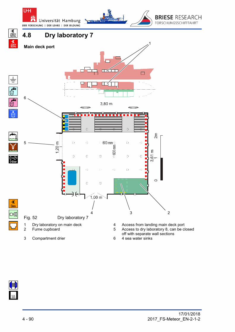
4.8 Dry laboratory 7
Main deck port 1
6
5
4 3 2
Fig. 52 Dry laboratory 7
1 Dry laboratory on main deck 4 Access from landing main deck port 2 Fume cupboard 5 Access to dry laboratory 8, can be closed
off with separate wall sections 3 Compartment drier 6 4 sea water sinks

17/01/2018 2017_FS-Meteor_EN-2-1-2 4 - 91
1 2 3
4
Fig. 53 Dry laboratory 7
1 Fume cupboard 3 Network connections (LAN) 2 Compartment drier 4 Access to dry laboratory 8
can be closed off with separate wall sections

17/01/2018 4 - 92 2017_FS-Meteor_EN-2-1-2
1 2 3 4 5 6 7
8
9
14
10
13 12 11
Fig. 54 Dry laboratory 7
1 Water from water purifier 8 Connections for control monitors 2 Compressed air 0-6 bar, oil separated 9 Network connections (LAN) 3 2x distillate from vapouriser 10 Double socket 4 Hot/cold water 11 Antennae socket 5 2x pure sea water (rotary pump) 12 Connections to data distribution system 6 Telephone 13 Intercom science 7 Hand shower 14 Data port hydrosweep+science

17/01/2018 2017_FS-Meteor_EN-2-1-2 4 - 93
1 1 2 3 4
7 6 5 Fig. 55 Dry laboratory 7 (detailed plan laboratory walls, status 1986)
1 Double sockets 5 Communication connections 2 Fume cupboard 6 Access to dry laboratory 8, can be closed off with
separate wall sections 3 Access from landing main deck port 4 Cable feed through 7 Telephone

17/01/2018 4 - 94 2017_FS-Meteor_EN-2-1-2
4.9 Dry laboratory 8
Main deck port 1
2
3
4
6 5
Fig. 56 Dry laboratory 8
1 Dry laboratory 8 on main deck 4 Laboratory cleaning machine 2 4 sea water sinks 5 Access from landing main deck port 3 Access to dry laboratory 7, can be closed off
with separate wall sections 6 Deep freezer space -80 °C

17/01/2018 2017_FS-Meteor_EN-2-1-2 4 - 95
1 2 3
4
Fig. 57 Dry laboratory 8
1 Telephone 3 Passage to dry laboratory 7, 2 Laboratory dishwasher can be closed off with separate wall
sections 4 Deep freezer space -80 °C

17/01/2018 4 - 96 2017_FS-Meteor_EN-2-1-2
1 2 3 4 5 6 7
8
14
9
13
12
11
10 Fig. 58 Dry laboratory 8
1 Double socket 8 Intercom science 2 Network connections (LAN) 9 4 pure sea water taps (membrane pump) 3 Double socket 10 PC workplace (example) 4 Connections to data distribution system 11 Wall shelf with PC 5 Connections for control monitors 12 Network connections (LAN) 6 Connections to data distribution system 13 Horizontal C-rails 7 Antennae socket 14 Vertical C-rails

17/01/2018 2017_FS-Meteor_EN-2-1-2 4 - 97
1 2 3 4 5 6
8 7 1
Fig. 59 Dry laboratory 8 (detailed plan laboratory walls, status 1986)
1 Double sockets 5 Cable feed through 2 Earthing bolts M10 (potential
equalisation) 6 Access from landing main deck port
3 Access to dry laboratory 7, can be closed off with separate wall sections
7 Shelves
4 Laboratory cleaning machine 8 Deep freezer space-80 °C

17/01/2018 4 - 98 2017_FS-Meteor_EN-2-1-2
4.10 Measurement and registration room 9
Main deck port 1
2
6 3
5 4
Fig. 60 Measurement and registration room 9
1 Measurement and registration room on main deck
4 Cable feed through
2 Posidonia 6000 operating unit 5 Access from staircase 3 Hand wash sink 6 Access to wet laboratory 10

17/01/2018 2017_FS-Meteor_EN-2-1-2 4 - 99
1
2
3
10 4
5
6
9
7
8
Fig. 61 Measurement and registration room 9
1 CTD monitor 6 CTD PC 2 DSHIP or Posidonia monitor 7 Double sockets 3 Posidonia monitor pull-out 8 Access to wet laboratory 10 4 Posidonia deck unit 9 Cable feed through 5 CTD deck unit 10 Posidonia PC

17/01/2018 4 - 100 2017_FS-Meteor_EN-2-1-2
1 2 3 4 5
7 6
Fig. 62 Measurement and registration room 9
1 Access to staircase aft ship port 5 Access to wet laboratory 10 2 Network connections (LAN) 6 Hand wash sink 3 Additional folding table 7 Operating unit Posidonia 6000 4 Securing rails for C-rail fitting

17/01/2018 2017_FS-Meteor_EN-2-1-2 4 - 101
1 2 3 4 5 6 7
12 11 10 9 3 8 Fig. 63 Measurement and registration room 9 (detailed plan, status 1986)
1 Connection for control monitors 7 Connection measurement data distributor 2 Intercom science 8 Thermosalinograph (optional) 3 Cable feed throughs 9 Access to staircase aft ship port 4 Network connections (LAN) 10 Telephone 5 Connection winches W 2,3,12 11 Compressed air 0-6 bar, oil separated 6 Operating unit Posidonia 6000 12 Hand wash sink

17/01/2018 4 - 102 2017_FS-Meteor_EN-2-1-2
4.11 Wet laboratory 10
Main deck port 1
2
8
3
7 4
6 5
Fig. 64 Wet laboratory 10
1 Wet laboratory 10 on main deck 5 Direct access from working deck 2 4 sea water sinks 6 Wet work table with run offs 3 Access to measurement/registration room 7 Double wash basin 4 Load lift to scientific stowage II 8 Additional folding table

17/01/2018 2017_FS-Meteor_EN-2-1-2 4 - 103
1
2 2
Fig. 65 Wet laboratory 10
1 Wet work table 2 Water connections at the ceiling of the room

17/01/2018 4 - 104 2017_FS-Meteor_EN-2-1-2
1 2 3 4 5 6 7
8
9
1
10
12 11 Fig. 66 Wet laboratory 10
1 Double sockets 7 Loudspeaker for announcements 2 Dataport hydrosweep/science 8 Intercom science 3 380 V connection with switch 9 Sea water taps (membrane pump) 4 Connections to data distribution system 10 Access to hoist to science 2 5 Connections for control monitors 11 Access to the measurement and
registration room 9 6 Antennae socket 12 Cable feed through

17/01/2018 2017_FS-Meteor_EN-2-1-2 4 - 105
1 2 3 4 5 6
10 6 7 5 9 8 2 7 Fig. 67 Wet laboratory 10 (detailed plan laboratory walls, status 1986)
1 Access to the work deck for the aft ship 6 Draining rack 2 Cable feed throughs 7 Large double sink 3 Double sockets 8 Network connections (LAN) 4 Dataport hydrosweep/science 9 Telephone 5 Sea water taps (membrane pump) 10 Access to the work deck for the aft ship

17/01/2018 4 - 106 2017_FS-Meteor_EN-2-1-2
4.12 Air gun room 11
Main deck 1
2
4
3
Fig. 68 Air gun room 11
1 Air gun room 11 on main deck 3 Direct access from working deck 2 Workbench 4 Air pulse fittings
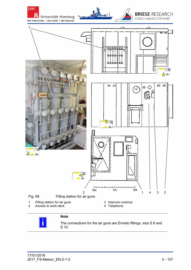
17/01/2018 2017_FS-Meteor_EN-2-1-2 4 - 107
1
2 1 4 3 2 Fig. 69 Filling station for air guns
1 Filling station for air guns 3 Intercom science 2 Access to work deck 4 Telephone
Note
The connections for the air guns are Ermeto fittings, size S 8 and S 10.

17/01/2018 4 - 108 2017_FS-Meteor_EN-2-1-2
4.13 Gravimeter room 12
Main deck 1
2
4
3
Fig. 70 Gravimeter room 12
1 Gravimeter room on main deck 3 Access to main landing 2 Gravimeter base 4 Air conditioning appliance (optional)

17/01/2018 2017_FS-Meteor_EN-2-1-2 4 - 109
1 2 3 4 5
4 8 7 5 6 Fig. 71 Gravimeter room 12 (detailed plan of laboratory walls, version 1986)
1 Air conditioning appliance (optional) 5 Wooden platform 2 Telephone 6 Access to main landing 3 Intercom science 7 Cable feed through 4 Double sockets 8 Network connections (LAN)

17/01/2018 4 - 110 2017_FS-Meteor_EN-2-1-2
4.14 Drawing room 13
Main deck starboard 1
2
8
7 3
6
4
5
Fig. 72 Drawing room 13
1 Drawing room on main deck 5 Network printer / scanner 2 Photocopier 6 Large drawing table 3 Access to conference room main deck 7 Network printer 4 A0 plotter 8 Access from landing main deck starboard

17/01/2018 2017_FS-Meteor_EN-2-1-2 4 - 111
1 2 3 4
3
5
6
Fig. 73 Drawing room 13
1 Network printer 4 Network printer / scanner 2 Photocopier 5 Access to conference room main deck 3 A0 plotter 6 Large drawing table
17/01/2018 4 - 112 2017_FS-Meteor_EN-2-1-2
1 2 3 4
5
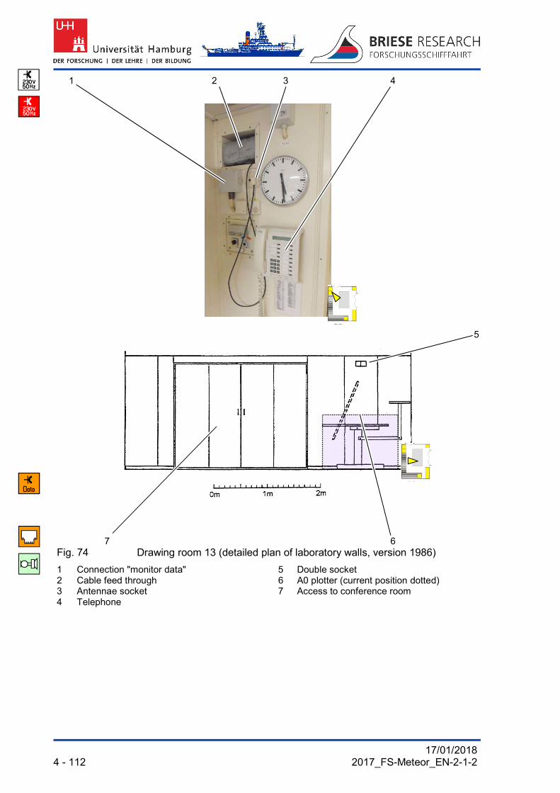
7 6 Fig. 74 Drawing room 13 (detailed plan of laboratory walls, version 1986)
1 Connection "monitor data" 5 Double socket 2 Cable feed through 6 A0 plotter (current position dotted) 3 Antennae socket 7 Access to conference room 4 Telephone

17/01/2018 2017_FS-Meteor_EN-2-1-2 4 - 113
1 2 3 4
7 6 5 4 1
Fig. 75 Drawing room 13 (detailed plan of laboratory walls, version 1986)
1 Communication connections 5 Hanging shelf 2 Access to main landing starboard 6 Hanging lockers 3 Network connections (LAN) 7 A0 plotter (current position dotted) 4 Double sockets

17/01/2018 4 - 114 2017_FS-Meteor_EN-2-1-2
4.15 Universal laboratory 15
Main deck starboard 1
4
3
2
Fig. 76 Universal laboratory 15
1 Universal laboratory on main deck 3 Access to geo laboratory 16 2 4 small sea water basins 4 Access from landing main deck starboard

17/01/2018 2017_FS-Meteor_EN-2-1-2 4 - 115
1 2 3 4
1
5
6
Fig. 77 Universal laboratory 15
1 Cable feed throughs 4 Junction box winches W 2,3,12 2 Access to geo laboratory 16 5 Large sink 3 Connections measurement data distributors 6 Access to landing main deck starboard

17/01/2018 4 - 116 2017_FS-Meteor_EN-2-1-2
1 2 3 4 5 6 7 8 9
10
11 11
14 13 12 Fig. 78 Universal laboratory 15
1 Junction box magnetometer winch 8 Double socket 2 Antennae socket 9 Compressed air 0-6 bar, oil separated 3 Connections for control monitors 10 Telephone 4 Connections to data distribution system 11 Sea water taps (rotary pump) 5 Earthing bolts M10 (ship's earth) 12 Network connections (LAN) 6 Connections hydrosweep/science 13 Large sink 7 Intercom science 14 Draining rack

17/01/2018 2017_FS-Meteor_EN-2-1-2 4 - 117
1 2 3 4 5 6 7 8
10 4 9 7
Fig. 79 Universal laboratory 15 (detailed plan of laboratory walls, version 1986)
1 Connections measurement data distributors
6 Draining rack
2 Network connections (LAN) 7 Double sockets 3 Access to main landing starboard 8 Junction box winches W2, W3, W12 4 Cable feed throughs 9 Access to geo laboratory 16 5 Large sink 10 Communication connections

17/01/2018 118 - 4 2017_FS-Meteor_EN-2-1-2
4.16 Geo laboratory 16
Main deck starboard 1
10
9
8
2
3
7
6 5 4
Fig. 80 Geo laboratory 16
Key:
1 Geo laboratory 16 on main deck 6 Compartment drier 2 Access to universal laboratory 7 Direct access from working deck 3 Crane track 8 Drinking water basin 4 4 small sea water basins 9 Work table 5 Refrigerator 10 Access from landing main deck starboard

17/01/2018 2017_FS-Meteor_EN-2-1-2 4 - 119
1 2
6
3
5 4
Fig. 81 Geo laboratory 16
1 Drinking water tap 4 Sea water taps (rotary pump) 2 Communication connections 5 Passage to universal laboratory 15 3 Cable feed through 6 Control box for crane track

17/01/2018 120 - 4 2017_FS-Meteor_EN-2-1-2
1 2 3 4 2 2
5
2
2
11
10
6
1 Communication connections 9
2 Transverse rails for crane track
3 Access to landing main deck starboard
4 Cable feed through
5 Double sockets
6 Large double sink 4 7 Access to the work deck for the aft ship
8 Draining rack
9 Refrigerator
10 Compartment drier
11 Lengthways rails and crane block of the crane track
8 6 7 1 Fig. 82 Geo laboratory 16

17/01/2018 2017_FS-Meteor_EN-2-1-2 4 - 121
1 2 3 4 5 6
4
7
9
8
Fig. 83 Geo laboratory 16
1 Large double sink 6 Access to the work deck for the aft ship 2 Compressed air 0-6 bar, oil separated 7 PC with Seacat software for mobile sound
probes 3 Hot/cold water and pure sea water (rotary pump) 8 Connector for mobile sound probe 4 Longitudinal rail of the crane track SWL
2000 kg 9 Connecting socket of on-board hydrophone
at mobile triggering units 5 Transverse rail of movable crane track (pos. 4)

17/01/2018 122 - 4 2017_FS-Meteor_EN-2-1-2
4.17 Filling room 17
Main deck midships 1
2
3
6
5
4
Fig. 84 Filling room 17
1 Filling room on main deck 4 Direct access from working deck 2 Hoist to machine room middle deck 5 Suspension crane track SWL 900 kg 3 Access from landing main deck starboard 6 Sounding shaft
17/01/2018 2017_FS-Meteor_EN-2-1-2 4 - 123
1 2 3 4 5
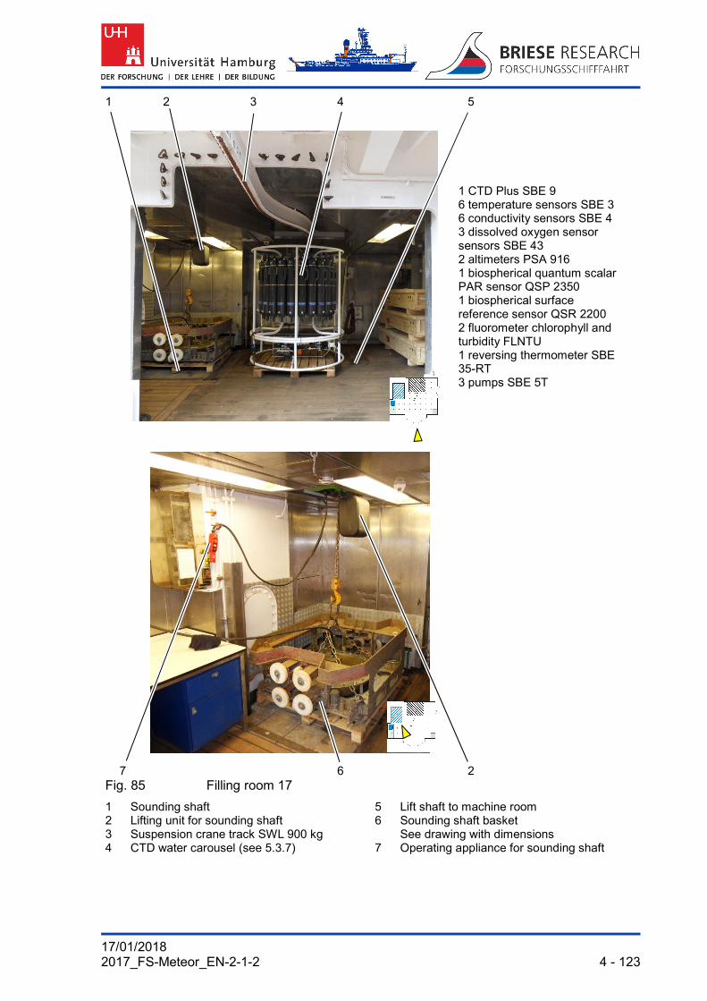
1 CTD Plus SBE 9 6 temperature sensors SBE 3 6 conductivity sensors SBE 4 3 dissolved oxygen sensor sensors SBE 43 2 altimeters PSA 916 1 biospherical quantum scalar PAR sensor QSP 2350 1 biospherical surface reference sensor QSR 2200 2 fluorometer chlorophyll and turbidity FLNTU 1 reversing thermometer SBE 35-RT 3 pumps SBE 5T
7 6 2 Fig. 85 Filling room 17
1 Sounding shaft 5 Lift shaft to machine room 2 Lifting unit for sounding shaft 6 Sounding shaft basket 3 Suspension crane track SWL 900 kg See drawing with dimensions 4 CTD water carousel (see 5.3.7) 7 Operating appliance for sounding shaft

17/01/2018 124 - 4 2017_FS-Meteor_EN-2-1-2
1 2 3 4 5 6
11 7
1
8
10 9 Fig. 86 Filling room 17 (detailed plan laboratory walls, status 1986)
1 Double sockets 6 Operating appliance for sounding shaft 2 Intercom science 7 Cable feed ADCP 3 Junction box ADCP 8 Network connections (LAN) 4 Hot/cold water and pure sea water 9 Access to landing main deck starboard (from rotary pump) 10 Cable clamps to the measurement and registration
room 9 5 Compressed air 0-6 bar, oil separated 11 Telephone

17/01/2018 2017_FS-Meteor_EN-2-1-2 4 - 125
1 2 3 4 5 6
9 8 3 7 Fig. 87 Filling room 17 (detailed plan laboratory walls, status 1986)
1 High voltage sockets 380V 16/32 A 6 Telephone 2 Cable feed through 7 Intercom science 3 Installation space lifting unit sounding shaft 8 Compressed air 0-6 bar, oil separated 4 Suspension crane track SWL 900 kg 9 Sink with hot/cold water and pure sea water 5 Access to the work deck for the aft ship

17/01/2018 126 - 4 2017_FS-Meteor_EN-2-1-2
4.18 Measurement and sounding room 18
Tween deck midships 1
2
5 3
4
Fig. 88 Measurement and sounding room 18
1 Measurement / sounding room on tween deck
4 Access from the scientific stowage 1
2 Seawater sampling from TSG 5 Access to the bow thruster room 3 Parasound electronics

17/01/2018 2017_FS-Meteor_EN-2-1-2 4 - 127
4 5
3
2
6
1
7
8
12 11 10 9 8 Fig. 89 Thermosalinograph in ground measurement room below measuring
and sounding room 18
1 Debubbler Measurement and sounding room drawing 18 2 Venting valves 8 Telephone, intercom, science 3 Sea water valves of thermosalinographs 9 Access to the bow thruster room 4 Display of flow rate (DFM) 10 Parasound electronics 5 Thermosalinographs 11 Hand wash sink 6 Valves upstream of filters 12 Access from staircase and 7 sea water inlet valves in bilge scientific stowage 1

17/01/2018 128 - 4 2017_FS-Meteor_EN-2-1-2
4.19 Air conditioned laboratory unit 19
Tween deck midships 1 2
3
6
5
4
Fig. 90 Air conditioned laboratory unit 19
1 Refrigeration room (-2 to -25 °C) 4 Deep freezer -80 °C 2 Refrigeration room (-2 to -25 °C) 5 4 sea water sinks 3 Air conditioned laboratories on tween deck 6 Access from staircase

17/01/2018 2017_FS-Meteor_EN-2-1-2 4 - 129
1 2 3 4 5
6
2
7 Air conditioned laboratories and refrigeration room: Laboratory and
measuring room
1 Laboratory and measuring room (+2 to 25 °C)
5 Sink with hot/cold water/pure sea water
2 Access to the refrigeration room 6 Sea water (membrane pump) 3 Intercom science 7 Refrigeration room (-2 to -25 °C) 4 Telephone

17/01/2018 130 - 4 2017_FS-Meteor_EN-2-1-2
1 2 3 1 4 2
5
8
6
7
5
Fig. 92 Air conditioned laboratory unit: Aquarium cold room (photo), laboratory and measuring room (plan)
1 Pure sea water taps (membrane pump) 5 Access laboratory and measurement room/aquarium cold store
2 Compressed air 0-6 bar, oil separated 6 Access from staircase 3 Hot/cold water 7 Access to refrigeration room (-2 to -25 °C) 4 Draining rack 8 Deep freezer -80 °C

17/01/2018 2017_FS-Meteor_EN-2-1-2 4 - 131
1 2 3 4
7 6 5 1 Fig. 93 Aquarium refrigeration room (detailed plan laboratory walls, status 1986)
1 Large sink 5 Pure sea water taps, compressed air, oil separated
2 Cable feed through 6 Work table 3 Access from laboratory and measurement
room 7 Deep freezer -80 °C
4 Double sockets
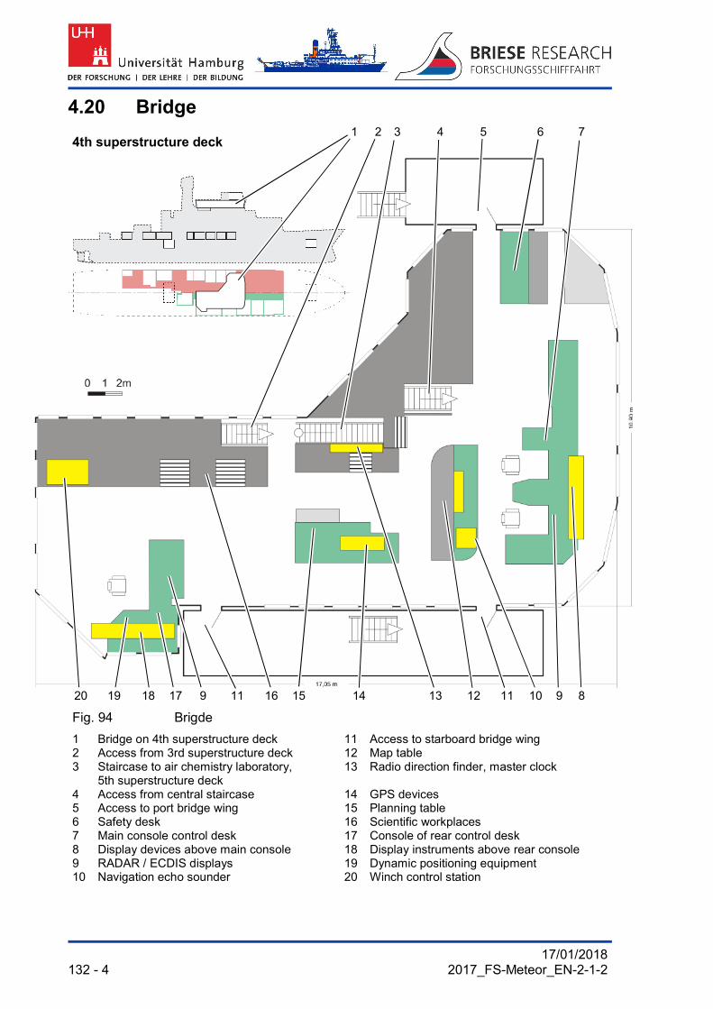
17/01/2018 132 - 4 2017_FS-Meteor_EN-2-1-2
4.20 Bridge
4th superstructure deck 1 2 3 4 5 6 7
20 19 18 17 9 11 16 15 14 13 12 11 10 9 8
Fig. 94 Brigde
1 Bridge on 4th superstructure deck 11 Access to starboard bridge wing 2 Access from 3rd superstructure deck 12 Map table 3 Staircase to air chemistry laboratory,
5th superstructure deck 13 Radio direction finder, master clock
4 Access from central staircase 14 GPS devices 5 Access to port bridge wing 15 Planning table 6 Safety desk 16 Scientific workplaces 7 Main console control desk 17 Console of rear control desk 8 Display devices above main console 18 Display instruments above rear console 9 RADAR / ECDIS displays 19 Dynamic positioning equipment 10 Navigation echo sounder 20 Winch control station

17/01/2018 2017_FS-Meteor_EN-2-1-2 4 - 133
1 2
10
3
5
9
8
7 3
6 1 5 4
Fig. 95 Bridge
1 Rear console (Fig. 94/17) 6 RADAR / ECDIS monitors (Fig. 94/9) 2 Main console (Fig. 94/7) 7 Dynamic positioning (Fig. 94/19) 3 Map table (Fig. 94/12) 8 Display instruments above console
(Fig. 94/18) 4 Scientific workplaces (Fig. 94/16) 9 Main console (Fig. 94/7) 5 Staircase to air chemistry laboratory,
5th superstructure deck 10 Display instruments above console
(Fig. 94/8)

17/01/2018 134 - 4 2017_FS-Meteor_EN-2-1-2
4.21 German Meteorological Service (DWD)
2nd superstructure deck, port 1 2
3 1 4 3 Fig. 96 (DWD) container with balloon ascent
1 DWD container on the rear forecastle deck 3 Balloon container in DWD container 2 DWD on board weather service on the 2nd
superstructure deck 4 Balloon ascent

17/01/2018 2017_FS-Meteor_EN-2-1-2 4 - 135
4.21.1 Tasks of the on board weather service The on board weather service on the expedition vessel METEOR – a station of the German Meteorological Service (DWD) – is a fixed installation on board.
It is located on the 2nd superstructure deck on the forecastle side ("green deck").
On research expeditions it is permanently manned by a weather radio technician and if required also a qualified meteorologist of the DWD. Both are competent in questions of maritime meteorology and the interpretation of meteorological data.
The tasks of the on board weather service essentially consist of the following items:
As ship use and research activity are weather and sea dependent, the ship's officers and expedition leaders receive meteorological advice with the aim of safe and optimum carrying out of research tasks. Therefore, scientific appliances and equipment can be used without damage to the ship and its equipment. The basis of this advice is meteorological data material from the area where the ship is being used and the wider surroundings. These are weather observations from ships, buoys and land stations, map material prepared by national weather services, forecast maps of the German Weather Service received by E-Mail from DWD in Hamburg and from the European Centre for Medium-Term Weather Forecasting in Reading (ECMWF) and appropriate sea forecasts. Satellite images also play a big part in the assessment and interpretation of weather conditions and development.
Generation of short and medium term (up to 10 days) weather forecasts or warnings for the relevant area of travel and use.
Recording, testing and preparation of the ongoing meteorological data gained on board. They serve as basic material for scientific examinations on the part of the participating groups and for DWD and are incorporated directly into the advisory activity of the on board weather service.
Some of these measurement data are already fed into the worldwide data exchange of the GTS (Global Telecommunication System) during the journey according to the international standard of the WMO (World Meteorological Organization)
4.21.2 Meteorological Advice Weather forecasts and warnings for various time scales are created on the basis of meteorological data material from the area of use and the wider surrounding area. Short term weather forecasts (up to 36 hours) and warnings support the ship's officers and expedition leaders in the up to date planning and implementation of ship use and research activity.

17/01/2018 136 - 4 2017_FS-Meteor_EN-2-1-2
1
2
Fig. 97 DWD weather service
1 Weather technician workplace 2 Workplace meteorologist

17/01/2018 2017_FS-Meteor_EN-2-1-2 4 - 137
Medium term prognoses (up to 10 days) of the DWD and other meteorological centres serve as a basis for the planning of subsequent engagements and thereby make a contribution to the optimum exploitation of ship times.
In this, satellite images received on board are assessed and interpreted and added to map material prepared by national weather services (analyses, prognoses). This map material is increasingly received by satellite supported channels of communication (E-Mail) as only as small number of short wave transmitters (e.g. DWD transmitter Pinneberg) air such products. First of all the model chains of the German Meteorological Service (GME model) and the EZMW and the subsequent products based on them like swell prognoses etc. are used.
4.21.3 Data recording The ongoing meteorological data must be recorded, tested and prepared. They are not just incorporated in the advisory work. They also serve as basic material for scientific examinations on the part of the participating groups of scientists and also later examinations by the German Meteorological Service. Some of these measurement data are fed into the worldwide data exchange of the GTS during the journey in accordance with the international standard within the framework of the GOS (Global Observing System) of the WMO.
4.21.4 Trajectory data The on board weather service on RV METEOR can if required make trajectory data available for scientific investigations daily via the German Meteorological Service in Offenbach by e-mail. This request for trajectory data must be made to the on board weather service prior to the start of the section of the expedition.
With the help of trajectory data the path of air particles at various heights (ground up to a pressure surface of 50 hPa) can be traced back to the ship position within a time period of up to 108 hours before their arrival. Therefore they can be used by air chemical working groups as reference values for investigations into the origin and further removal of air impurities for example.
Current trajectory data are made available in the on board weather service as complete map plots or raw data files.
For further detailed information (measurement instruments, data recording) on the RV METEOR on board weather service in the form of a PDF file (approx 2.5 MB) see www.dwd.de.

17/01/2018 138 - 4 2017_FS-Meteor_EN-2-1-2
4.22 Conference room
Main deck starboard 1 2
7 6 5 4 3 Fig. 98 Conference room
1 Conference room on the main deck 4 Projector below ceiling 2 Access from landing main deck starboard 5 Lectern (easily movable) 3 Access to library (key from ship’s doctor) 6 Projection screen
7 Access to drawing room

17/01/2018 2017_FS-Meteor_EN-2-1-2 4 - 139
1 2 3
4
Fig. 99 Conference room
1 Beamer 3 Projection screen 2 Various playing appliances 4 Lectern
Note
The arrangement of the tables shown can be changed if required.

17/01/2018 140 - 4 2017_FS-Meteor_EN-2-1-2
4.23 Library
Main deck starboard 1
5 4 3 2 Fig. 100 Library
1 Library on main deck starboard 4 Cabinet 2 Shelves 5 Access from conference room 3 Table

17/01/2018 2017_FS-Meteor_EN-2-1-2 4 - 141
Fig. 101 Library
Note
The key to the on board library is held by the doctor.

17/01/2018 142 - 5 2017_FS-Meteor_EN-2-1-2
5. APPLIANCES AND EQUIPMENT 5.1 Hydro acoustic equipment and measurement
appliances
Fig. 102 Echo sounder KONGSBERG EM 710 and EM 122

17/01/2018 2017_FS-Meteor_EN-2-1-2 5 - 143
5.1.1 Echo sounder for bathymetric measurement
Kongsberg EM 710 1° x 1°
The appliance enables extensive hydrographic measurement in flat sea areas up to a depth of 2,000 m and the recording of the morphological structures. These can be represented on maps as isolines or grids.
Manufacturer Kongsberg Maritime A/S, Norway
Frequency 70 – 100 kHz
Properties Echo sounder with 432 beams
Radiation angle up to 140° transverse to ship's axis
Range up to 2,000 m
Measurement width Depth/substrate dependent, max. 5.5 times water depth
Hardware 2 operator-PC
2 post-processing-PC
Location one in the sounding centre and one in the drawing room
Display The data is shown online on the operator PC and the helmsman display PC (bridge).
Real-time colour display with 2D or 3D ground map and isoline plot.
Data issue Printouts of display in Postscript and then on A3 laser printer or A0 colour plotter.
The data is stored in binary for further processing with the Neptune software, output in ASCII format.
Operating software Seafloor Information System SIS v3.7
Post processing-software Neptune
Data storage Raw data on DVD, hard drive, DAT tape
Corrections Roll, pitch, heave
Calibration via waterborne sound speed (input / fixed probe)
via waterborne sound profile (mobile probe)
with help of data of a CTD
Transducer / sensor installation location
Between rib 102 and 105
Note
Supervisors and trained scientific personnel must be provided for the operation, water-borne sound profiles and the post processing of the data.

17/01/2018 144 - 5 2017_FS-Meteor_EN-2-1-2
5.1.2 Echo sounder for bathymetric deep sea measurement
1 2
4 3 Fig. 103 Echo sounders KONGSBERG EM 710 and EM 122
1 Receiving transducer EM 710 3 Receiving transducer EM 122 2 Transmission transducer EM 710 4 Transmission transducer EM 122

17/01/2018 2017_FS-Meteor_EN-2-1-2 5 - 145
Kongsberg EM 122 1° x 2°
The appliance enables extensive hydrographic measurement in sea areas up to a depth of 11,000 m and the recording of the morphological structures. These can be represented on maps as isolines or grids.
Frequency 12 kHz
Properties Echo sounder with 400 beams
Radiation angle up to 140° transverse to ship's axis
Range up to 11,000 m
Measurement width > 5.5-times water depth
Hardware 2 operator-PC
2 post-processing-PC
Location one in the sounding centre and one in the drawing room
Display The data is shown online on the operator PC and the helmsman display PC (bridge). Real-time colour display with 2D or 3D ground map and isoline plot.
Data issue Printouts of display in Postscript and then on A3 laser printer or A0 colour plotter. The data are saved in a binary way for further processing with Software Neptune, issue in ASCII format is possible.
Operating software Seafloor Information System SIS v3.7
Post processing-software Neptune (issue in ASCII-Code possible)
Data storage Raw data on DVD, hard drive or DAT tape
Corrections Roll, pitch, heave
Calibration via waterborne sound speed (input / fixed probe)
via waterborne sound profile (of mobile probe)
Installation position transducer
between rib no. 87 and 101
Note
Quantity of data depending on depth 1 – 4 GB/month
Processing time 5 – 6 hours per day of measurement
Data archiving in DOD, BSH Hamburg
Note
Supervisors and trained scientific personnel must be provided for the operation, water-borne sound profiles and the post processing of the data.

17/01/2018 146 - 5 2017_FS-Meteor_EN-2-1-2
Fig. 104 Screen presentation on echo sounder KONGSBERG EM 710

17/01/2018 2017_FS-Meteor_EN-2-1-2 5 - 147
“Neptune” Postprocessing Software
Description Neptune is a software for recording, visualisation and post processing of the echo sound data. Neptune therefore represents a comprehensive postprocessing package for hydrographic measurements.
Hardware 2 post processing-PCs with DVD, USB connection and external hard drive
Work places 1 for each post processing PC
in the computer room
in the drawing room (laboratory 13)
Data editing The following data can be corrected retrospectively:
Position
Course
Depth (with depth distorted values)
Profile definition
Waterborne sound speed
Data reduction is possible.
Presentation Map extract and scale can be freely selected
Isoline, map grid and transverse profiles on plotter possible
Data issue Laser printer A3 and colour plotter A0
Data import and export via
DVD
USB
Mobile hard drive
Operator PC network
External computers via TCP/IP, FTP (Twisted Pair)

17/01/2018 148 - 5 2017_FS-Meteor_EN-2-1-2
5.1.3 Deep sea sediment echo sounder
Fig. 105 Appliance chart "Parasound P70"

17/01/2018 2017_FS-Meteor_EN-2-1-2 5 - 149
Parasound DS-3 / P70
Parasound is a sediment echo sounder with which the internal structures of the sedimentary sea bed covering are measured along the ship's course.
Manufacturer ATLAS HYDROGRAPHIC GmbH, Bremen
Frequencies: Frequency Radiation angle
Primary High Frequency PHF 1 18 – 33 kHz 4.0° x 4.5° (18 kHz)
2.2° x 2.5° (33 kHz)
Primary High Frequency PHF 2 18.5 – 39 kHz
Primary Low Frequency PLF 3 – 12 kHz 24.0° x 28.0° (3 kHz)
6.0° x 7.0° (12 kHz)
Secondary High Frequency SHF 36.5 – 40 kHz 2.0° x 2.3°
Secondary Low Frequency SLF 0.5 – 6.0 kHz 4.5° x 5.0°
Range 10 m – 10,000 m
Sediment penetration Up to over 200 m, depending on water depth and sediment
Resolution Up to 15 cm
Note
With a ground inclination > 4° no more penetration!
Hardware 1 Operator-PC with DVD drive
Location operating appliance Sounding centre
Display Echogram presentation on operator PC (online and offline)
Issue Print outs by colour printer
Compensation Roll (>+/- 20°), pitch (> +/-10°), heave (> +/- 5 m)
Transducer / sensor installation location
Between rib 126 and 127, midships
Note
Supervisors and trained scientific personnel must be provided for the operation and the post processing of the data.
Note
You can find further information in the ATLAS Parasound P70 handbook which can be dowloaded from the website of the control centre.

17/01/2018 150 - 5 2017_FS-Meteor_EN-2-1-2
Fig. 106 Screen presentation sediment echo "Parasound"

17/01/2018 2017_FS-Meteor_EN-2-1-2 5 - 151
Parastore-3 postprocessing system
Description Parastore-3 is a software for the recording, visualisation and post processing of the Parasound data. It is possible to present and print out echograms, spectograms and single traces in several instances. Several numerical or graphical processing algorithms can be applied in order to improve the graphic quality of the data.
Workplace Operator-PC in the sounding centre
Data The raw data are deposited by Parasound 3 in asd format (“atlas sound data” format). The raw data contain the data of the complete water column. In order to extract the relevant part of the sediment echo, the data can be extracted online or offline through a depth window. The data reduction occurs through automatic or manual carrying along of a data window and by sampling the traces. The offline processing is not possible during measurement operation. The export of the data occurs into the standard seismic data format SEG-Y. As an option storage can occur in PS3 format (Parasound data format of the University of Bremen).
Note
Supervisors and trained scientific personnel must be provided for operation of the software.
Note
The software is issued free of charge but in a controlled fashion by ATLAS HYDROGRAPHIC GmbH, Bremen to users in German institutions.

17/01/2018 152 - 5 2017_FS-Meteor_EN-2-1-2
5.1.4 Navigation echo sounder / echograph 1
2
4 3
Fig. 107 ELAC LAZ 5100 and repeater display DAZ 25
1 Navigation echo sounder ELAC LAZ 5100 3 Installation location repeater display 2 Navigation echo sounder installation location 4 Repeater display: DAZ 25

17/01/2018 2017_FS-Meteor_EN-2-1-2 5 - 153
ELAC LAZ 5100
Measurement of the water depth below the keel for navigation and for support of the scientific echo sounding equipment
Manufacturer L3 ELAC Nautik GmbH, Kiel
Frequency 100 kHz
Range 600 m
Hardware Display appliance (recorder) on map table
Digital display (ceiling console on the control console)
Installation locations Bridge front, starboard
Transducer / sensor installation location
Between rib 130 and 131, midships

17/01/2018 154 - 5 2017_FS-Meteor_EN-2-1-2
5.1.5 Acoustic Doppler current profiler 1
Fig. 108 ADCP
1 75 kHz transducer of the ADCP at rib 125

17/01/2018 2017_FS-Meteor_EN-2-1-2 5 - 155
ADCP
The appliance is for measurement of the current direction and speed in the water column.
Description The ADCP measures the relative current direction and current speed in the water column under the travelling ship with the help of the Doppler effect.
Subsequently a conversion into absolute values occurs with the data of the external GPS position sensor and the compass heading being incorporated.
There are two systems on board: Ocean Surveyor 38 kHz (OS38) and Ocean Surveyor 75 kHz (OS75). The 75 kHz appliance is installed at a fixed angle of 45°, the 38 kHz appliance is used in the hydrographic shaft at an installation angle of 0°.
Manufacturer Teledyne RD Instruments
Working frequencies
Frequency Range Installation position of the transducer
38 kHz up to 1,000 m Sounding shaft
75 kHz up to 400 m At rib 125
Note
The use of the other devices in the sounding shaft is restricted while the 38 kHz converter is being used.
Both transducers can be operated at the same time.
Location operating appliance ADCP-PC in the computer room
Data storage on PC
Software VmDas (Teledyne RD Instruments)

17/01/2018 156 - 5 2017_FS-Meteor_EN-2-1-2
5.1.6 Position sensor
Fig. 109 Position sensor MRU 5 in the machine workshop

17/01/2018 2017_FS-Meteor_EN-2-1-2 5 - 157
Position sensor MRU 5
The motion sensor measures roll, pitch, heading and the heave of the ship.
Description The data is given to the multibeam echo sounders EM710 and EM122, the sediment echo sounder Parasound P70 and to DSHIP with 100 Hz in Simrad3000 format via Seapath.
Manufacturer Kongsberg Maritime

17/01/2018 158 - 5 2017_FS-Meteor_EN-2-1-2
5.1.7 Seapath
Fig. 110 Seapath system

17/01/2018 2017_FS-Meteor_EN-2-1-2 5 - 159
Seapath 300
Description Seapath 300 is a positioning, position and heading sensor and combines the movement sensor data of the MRU with GPS satellite signals. The heart of the system consists of the MRU 5 (motion to reference unit) and two GPS.
Seapath was specially developed for hydrographic applications in which it is important to have the exact heading, position, heave, roll and pitch data with chronological synchronism. The combination of the movement data of the ship and an exact GPS position makes it possible to calculate correction data that is even more accurate, which is sent to the EM710 and EM122 multibeam echo sounders and the Parasound sediment echo sounder. The sounders can therefore compensate for the movements of the ship in the best possible way. Precise bathymetric maps can be produced in this way.
Manufacturer Kongsberg

17/01/2018 160 - 5 2017_FS-Meteor_EN-2-1-2
5.1.8 2-axis Doppler log
1
Fig. 111 SAM 4683 Doppler log (2-axis)
1 SAM 4683 installation location

17/01/2018 2017_FS-Meteor_EN-2-1-2 5 - 161
SAM 4683 Doppler log (2-axis)
Description The appliance works under water with the Doppler effect and on the basis of the satellite locating.
The Doppler-Log supplies the speed over ground in a lengthways and lateral direction and speed through water.
Manufacturer SAM Electronics / Skipper
Location operating appliance Bridge, front and various repeater displays
Installation position transducer
Spant 124 ship’s floor
Values issued The following are displayed via the device itself, the repeater displays and DSHIP:
Speed in lengthways direction
Speed in lateral direction
Speed through water
Rate of turn
Heading
Lateral speeds on bow and stern

17/01/2018 162 - 5 2017_FS-Meteor_EN-2-1-2
5.2 Other navigation and measurement appliances
5.2.1 Underwater positioning system 1
2
3
4
Fig. 112 Way of operation of the Posidonia appliance
1 GPS receiver determines ship position 3 ROV sends position signals 2 4 underwater sound transducers on the floor
receive/transmit position signals 4 Transponder or responder in device
transmits / receives position signals

17/01/2018 2017_FS-Meteor_EN-2-1-2 5 - 163
Posidonia 6000
The appliance helps determine the position of one or several underwater vehicles or objects e.g. anchorings up to a max water depth of 6,000 metres.
Description With the Posidonia 6000 the position of an underwater vehicle is determined with the time differences of acoustic position signals between 4 transmitters or receivers below the ship and a transponder or responder on the underwater vehicle being evaluated and placed in relation to DGPS signals.
Manufacturer iXSea SAS
Location operating appliance Posidonia-PC in the measurement and registry room
Display As an image on the Posidonia PC,
on the bridge as a position on the electronic map (ECDIS)
Data storage on PC
Installation position of the sensors
Floor, rib 106, midships
Transponders
Two mini transponders and a releaser are present for the Posidonia system:
Technical Data
Type Number Type
Transponders 3 Ixsea Oceano MT861S-R
Frequency range Low Frequency Band 8 kHz -16 kHz
Engagement depth 6000 m
Weight air/water 8 kg / 6 kg
Dimensions L = 450 mm, Ø 70 mm
Releaser 1 Ixsea Oceano RT861B2S
Frequency range Low Frequency Band 8 kHz -16 kHz
Engagement depth 6000 m
Weight air/water 25 kg / 16 kg
Dimensions L = 780 mm, Ø 130 mm

17/01/2018 164 - 5 2017_FS-Meteor_EN-2-1-2
5.2.2 Differential GPS (DGPS) 1
2
Fig. 113 C-Navigator, RhoTheta 300 radio direction finder
1 C-Navigator at planning table 2 C-Navigator installation location

17/01/2018 2017_FS-Meteor_EN-2-1-2 5 - 165
GPS C-Nav
The appliance supplies the position and time data for the multibeam echo sounders and the sediment echo sounder. The correction data are leased for the full year.
Two C-Nav 3050 DGPS receivers are present on board.
Manufacturer C&C Technologies
Installation point operating appliance
Bridge (planning table)
5.2.3 Global Positioning System (GPS) The following appliances are also present on board as additional GPS systems:
Shipmate GN30-2 (manufacturer Simrad)
Simrad HS50 (GPS-compass)

17/01/2018 166 - 5 2017_FS-Meteor_EN-2-1-2
5.2.4 VHF radio direction finder 1
2
Fig. 114 RhoTheta 300 radio direction finder, Gonio radio direction finder
1 RhoTheta 300 radio direction finder 2 Gonio radio direction finder

17/01/2018 2017_FS-Meteor_EN-2-1-2 5 - 167
RhoTheta 300
The device is used to take bearings on and locate scientific devices equipped with VHF transmitters.
Antenna position Top platform
Installation point operating appliance
Bridge (control panel)
Frequencies Aircraft radio band: 118.8 … 121.5 … 124.0 MHz in steps of 5 kHz
Marine radio band: 156 – 162.1 MHz in steps of 5 kHz
On board transmitter Model Novatech
Max. water depth 7300 m
Frequencies 154.585 MHz and 160.785 MHz
Gonio
There is a GONIO radio direction finder for ARGOS and SARSAT transmitters in the blue cabinet in air chemistry laboratory 1. This can be connected if required. The antenna cables have fixed routing from the mast and exit from the cable leadthrough in the wall.
Antenna position Top platform
Operating appliance storage location
Air chemistry laboratory 1
Frequencies 401.650 MHz ± 2 kHz (ARGOS)
406.025 MHz ± 2 kHz (SARSAT)

17/01/2018 168 - 5 2017_FS-Meteor_EN-2-1-2
5.2.5 GPS position sensor 1 2
Fig. 115 GPS position sensor
1 Antennae array GPS position sensor ADU-2 2 Installation location of central device ADU-2
(in air chemistry laboratory, 5th superstructure deck)

17/01/2018 2017_FS-Meteor_EN-2-1-2 5 - 169
ADU-2
As well as the usual GPS data, the system returns the roll and pitch values.
Description The data are recorded for use with the ADCPs.
Manufacturer Ashtech
Installation point operating appliance
Air chemistry laboratory
Installation position receiver Antennae array on the upper starboard mast yardarm
Data storage via DSHIP
5.2.6 Gyrocompass
Navigat X MK1
The compasses Navigat X and Navigat 2001/FOG work in parallel. The FOG is connected as main sensor, the Navigat X serves as a reserve system.
The speed error is corrected automatically.
Manufacturer C. Plath, Hamburg
Installation location Converter room next to the bridge
Retrospective turning gyrocompass
> 100° / sec
Roll and pitch freedom +/- 40°
Oscillation error < 0.1° secans* of the width
Static errors < 0.1° secans* of the width
Dynamic error < 0.4° secans* of the width
*: secans = 1/cosinus

17/01/2018 170 - 5 2017_FS-Meteor_EN-2-1-2
5.2.7 Fibre optic course and position reference system FOG
Fig. 116 Navigat 2100, compass displays

17/01/2018 2017_FS-Meteor_EN-2-1-2 5 - 171
Navigat 2100
The Navigat 2100 is a fully electronic, digital, fibre optic gyrocompass system in an adaptive strapdown technology.
Description An arrangement of three fibre optic gyroscopes and two electronic levels is able to determine geographical north. In this the turning speeds of the three fibreoptic gyroscopes and the signals of the electronic levels are used to calculate the earth's direction of rotation by using an adaptive Kalman filter. The northern direction is derived from this.
In addition to the angle information for heading, roll and pitch, the turning rates are also available as initial values. The roll and pitch values serve for compensation of the hydroacoustic plant equipped with appropriate entries e.g. Parasound, ADCP.
The data and the status are recorded, stored and distributed via the DSHIP.
Manufacturer C. Plath, Hamburg
Installation location Converter room next to the bridge
Measurement ranges
Course / z-axis 0° – 360°
Roll x-axis +/- 45°
Pitch y-axis +/- 45°
Rotation speeds (X, Y, Z) +/- 50°/sec
Accuracy
Course < 0.7°sec / width
Roll/pitch angle < 1.0°
Rotation speed (ROT) < 0.4°/min
X-/Y-rotation speeds < 0.4°/min
Area of use
Geographical width +/- 75°
Speed: +/- 75 kn

17/01/2018 172 - 5 2017_FS-Meteor_EN-2-1-2
5.3 Scientific work equipment
5.3.1 Hydrophone extension unit 1 2
Fig. 117 Transmit / receive characteristic transducer ITC–3013, triggering unit IXSEA TT-801
1 Transmit / receive characteristic transducer ITC–3013 2 Triggering unit IXSEA TT-801
The hydrophone extension unit is a universal extending unit for securing hydro-acoustic converters. At present the ship's own transducer is fitted.
However a user specific transducer can also be used. The exchange can take place with the ship afloat without docking.
Note
When using new transducers, the available space in the extension shaft must be taken into account.
Manufacturer Hoppe
Installation point operating appliance
Bridge, operation by bridge personnel
Hydrophone extension unit installation location
Foreship, ground measurement room between rib 123 and 124
Extension depth 600 mm below lower edge box keel
Hydrophone extension unit clearance width
125 mm, sufficient for e.g. OCEANO acoustic modules AM 121)
On board transducer International Transducer Corporation, Type ITC 3013
On-board triggering unit IXSEA, Type TT-801

17/01/2018 2017_FS-Meteor_EN-2-1-2 5 - 173
5.3.2 Deep freezers
Fig. 118 Deep freezer
National Lab GmbH, ProfiLine Taurus , type: PLTA 0986
The two freezers are used for storing samples at very low temperatures.
Temperature -40 to -80 °C
Dimensions (inner) L 385 mm, W 385 mm, H 470 mm
Contents each approx. 70 litres
Installation locations Clean laboratory 8 and aquarium refrigeration room
Note
Requirement should be stated in good time (>24 h in advance).
If samples remain on board for longer, it is requested that subsequent user groups are informed about fill level, duration of stay and ideal temperature.

17/01/2018 174 - 5 2017_FS-Meteor_EN-2-1-2
5.3.3 Thermosalinograph
4
5
3
2
1 6
7
8
8
9
13
12 11
10
Fig. 119 Thermosalinograph, temperature sensor SBE 38
1 Debubbler 8 Sea water filter 2 Venting valves for debubbler 9 Inlet connection installation location in bilge 3 Sea water valves to the TSG 10 Temperature sensor SBE 38 4 Flow meter display 11 Thermosalinograph in bow measurement
room 5 Thermosalinographs (TSG) 12 Water inlet connections Spt 134 port and
starboard 6 Fresh water flushing valves to the TSG 13 Measurement and sounding room 18 with
sampling 7 Valves upstream of sea water filters

17/01/2018 2017_FS-Meteor_EN-2-1-2 5 - 175
2 3 4 5 6 7 8 9 10 11 12
13
14
1 15
16
17
18
19
24 20
21
22
23
7
19 21 20 6
5
Fig. 120 Thermosalinograph, temperature sensor SBE 38
1 Floor measuring room (not accessible) 13 TSG drainage valves 2 Bow and sounding room (accessible) 14 Thermosalinograph 3 Thermosalinograph enclosure 15 Venting valves for debubbler 4 Fresh water access 16 Debubbler 5 Tap with hose for sampling 17 Sea water pump 6 TSG outlet 18 Sea water filter 7 Pressure retention valve 19 SVP (Sound Velocity Profiler) 8 Debubbler venting outlet 20 SBE38 temperature sensor 9 Flow meter sensor 21 Inlet connection installation location in bilge 10 TSG outlet valves 22 TSG drainage outlet 11 Fresh water flushing valves to the TSG 23 Water inlet connections in foreship Spt 134 12 Sea water valves to the TSG 24 Bilge

17/01/2018 176 - 5 2017_FS-Meteor_EN-2-1-2
SBE21 Seacat
The thermosalinograph is used to measure the temperature, conductivity and salt content of the sea water The water inlet connections are in the bulbous bow, several metres below the water line. An external temperature sensor is attached to the TSG.
Manufacturer Sea-Bird Electronics, inc.
Accuracy
Temperature 0.01 °C / 6 months
Conductivity 0.001 S/m/month
Resolution
Temperature 0.01 °C
Conductivity 0.0001 S/m
Measurement rate 6 sec
Installation location Measurement and registration room, laboratory 18
Calibration The sensors are regularly sent to the manufacturer for calibration.
Digital Oceanographic Thermometer SBE38
The Digital Oceanographic Thermometer SBE 38 is installed as an external temperature sensor upstream of the thermosalinographs, in order to obtain an exact water temperature. The sensors are embedded into the supply lines directly at the entry point on the outer shell of the ship at the level of the intake connections for the thermosalinographs.
Manufacturer Sea-Bird Electronics, inc.
Accuracy
Working area -5 … +35 °C
Starting accuracy 1 ± 0.001 °C (1 mK)
Stability 0.001 °C (1 mK) in 6 months (certified)
Resolution
Temperature 0.00025 °C (0.5 mK)
Calibration -1 … + 32 °C
Measurement error caused by self-warming
below 200 µK
Installation location Embedded in the supply lines at the outer skin of the ship at the entry point

17/01/2018 2017_FS-Meteor_EN-2-1-2 5 - 177
5.3.4 Sounding shaft
Fig. 121 Sounding shaft, sounding shaft basket and adapter plate

17/01/2018 178 - 5 2017_FS-Meteor_EN-2-1-2
The sounding shaft basket in the sounding shaft makes it possible to suspend sensors, samplers and other scientific appliances.
For this purpose one adapter plate acts as carrier of the appliances. There are two adapter plates on board.
Description The adapter plate used as appliance carrier is moved in the sounding by means of an electrically operated winch and locked hydraulically in the lower end position.
Note
The additional use of other devices in the sounding shaft is restricted while the 38 kHz ADCP converter is being used.
Installation location Filling room, laboratory 17, accessible from the working deck
Thickness of the plate 15 mm
Studs Ø 20, L 120 mm
Height of sounding shaft basket 440 mm
Hook height of the lifting equipment 1,920 mm above floor of the filling room
Deck clearance 2,150 mm
Height of floor above ship's floor approx. 6,400 mm
5.3.5 Water-borne sound detectors
Applied Microsystems SV Plus V2
Two mobile water-borne sound detectors are available on board for measuring the velocities of water-borne sound.
Manufacturer AML Applied Microsystems
Depth
2000 m AML Applied Microsystems SV Plus V2 SN 3498
5000 m AML Applied Microsystems SV Plus V2 SN 3757

17/01/2018 2017_FS-Meteor_EN-2-1-2 5 - 179
5.3.6 Core stacking frame 1 2
1 2
Fig. 122 Core stacking frame
1 Core stacking frame 2 Pivot with adapter on movebar

17/01/2018 180 - 5 2017_FS-Meteor_EN-2-1-2
The appliance assists in safely bringing various core unloading appliances with possible core lengths of up to 24 metres on or off the ship.
Manufacturer Elbe Hydraulik, Osterrönfeld
Description of structure Square pipe construction from hot dip galvanised steel
Load bearing capacity of the frame
Max. 6,000 kg
Note
The load capacity of the system is restricted to a maximum of 5,000 kg by the holding force of the positioning winch.
Components
Weights set-holder Number 1
Length 1,820 mm
Width 900 mm
Height 750 mm
Mass 450 kg
Core box / core pipe sensor frame
Number 3
Length each 5,700 mm
Width each 800 mm
Height each 750 mm
Mass each 550 kg
End frame with swing arm and wheels
Number 1
Length 1,200 mm
Width 1,074 mm
Height 770 mm
Mass 250 kg
Note
The core stacking frame is only on board if requested and if it is not used it will be removed!
If required, the maximum required length must be specified during the coordination meeting and entered in the device list in the minutes.

17/01/2018 2017_FS-Meteor_EN-2-1-2 5 - 181
5.3.7 CTD probe and water carousel
Fig. 123 CTD probe and water carousel

17/01/2018 182 - 5 2017_FS-Meteor_EN-2-1-2
Conductivity and temperature profiles in the water column are measured with a CTD probe (“Conductivity, Temperature, Depth”) (salt content calculated from this).
A CTD probe with water carousel is available on board as a back up for the CTDs people have brought with them.
The equipment consists of a water carousel with CTD, the on board appliance (Deck Unit) SBE-11 Plus (V2) and a PC with data recording.
SEASOFT from Sea-Bird Electronics is used as software.
Manufacturer Sea-Bird Electronics, inc.
Type designation SBE911Plus
Total weight of the frame Max. 200 kg
Number of water carousels 24 bottles ocean test equipment OTE 110B
Content / bottle 12 litres
Sensors present
Number Equipment
1 CTD Plus SBE 9
6 Temperature sensors SBE 3
6 Conductivity sensors SBE 4
3 Dissolved oxygen sensor SBE-43
2 Altimeter PSA 916
1 Biospherical quantum scalar PAR sensor QSP 2350
1 Biospherical surface reference sensor QSR 2200
2 Fluorometer chlorophyll and turbidity FLNTU
1 Reversing thermometer SBE-35 RT
3 Pumps SBE 5T
Note
The sensors must be calibrated regularly by the manufacturer and are not available on board during this time.

17/01/2018 2017_FS-Meteor_EN-2-1-2 5 - 183
5.3.8 Radiation protection container
Fig. 124 Radiation protection container

17/01/2018 184 - 5 2017_FS-Meteor_EN-2-1-2
Warning!
Danger of scatter contamination of the ship!
Do not under any circumstances bring contaminated sediments outside the container unintentionally!
Following completion of the work with radioactive substances and cleaning of the container, wipe tests must be carried out in line with the valid Ship Board Procedure (SBP).
A record of these wipe tests is kept.
One copy of this record (forms on board) goes to the next person in charge of safety (to be filed in the log book for the radiation protection container), to the chief and to Mr Rabsch (Institute for Marine Science, Kiel).
The next person responsible for safety must retest the wipe test values passed on to him by his predecessor when taking over the container as any possible contamination will otherwise be blamed on him.
Radiation protection container
The laboratory container is used for handling radioactive materials and sources in accordance with the certificate of approval of the container.
Safety level of the container:
Authorised activities involving handling radioactive emitters in accordance with handling license F 004-2.2/3–RS dated 20.10.1997 Laboratory container F.S. Meteor
Calculation of protection class in accordance with DIN 25425-1
Previous version: Handling type A and B
H-3: 1500 * FG 5MBq = 7500 MBq; 3000 MBq GJAZ => K = 2,5
C-14: 1500 * FG 0.5 MBq = 750 MBq; 90 MBq GJAZ => K = 8.33
P-32: 1500 * FG 0.5 MBq = 750 MBq; 6 MBq GJAZ => K = 125
S-35: 1500 * FG 0.5 MBq = 750 MBq; 30 MBq GJAZ => K = 25
Total of all K = 160.83
The container must be operated in accordance with the S2 directives as per DIN 25425-1 with this K value of 160 and handling types A and B.
An approval from the Kiel Ministry of Justice exists for the following isotopes: Open handling with the isotopes H-3, C-14, S-35, P-32 and P33.

17/01/2018 2017_FS-Meteor_EN-2-1-2 5 - 185
Fig. 125 View of inside of radiation protection container

17/01/2018 186 - 5 2017_FS-Meteor_EN-2-1-2
Owner German Federal Republic,
represented by the BMBF (Federal Ministry for Training and Research)
Contact for approval processes
Applications to work with radioactive materials must be submitted following consultation with the University of Hamburg, the shipping company and the Leitstelle Deutsche Forschungsschiffe (German Research Fleet Coordination Centre).
http://www.mpi-bremen.de/Strahlenschutzcontainer_FS_Meteor.html
Power supply 380 / 220 V AC
Connections Hot/cold water
Pure sea water
Working pressure 5 bar
Dimensions In line with 20' standard container
Mass approx. 7,500 kg
Set up location Space 1 and 2, forecastle deck rear
Note
For operation the container must be on deck!
Storage If the container is not on board, the sensitive items of equipment (scintillation counter, monitor etc) must be stored in a wooden box in scientific storage room 3.
Note
The organization of the radiation protection container on board F.S. Meteor has been subject to new regulations since 2010.
In order to allow the expeditions to run seamlessly, the registrations for the radioactive work must arrive punctually with the authorities. Working with radioactive isotopes is strictly prohibited without the relevant approval.
Dose rate measurement device
Radiometer FH 40 G-L
Manufacturer Eberline Instruments
Measurement range 0.01 uSv/h – 9.9 Sv/h
Radiation source Model By 24/80 No.1328
Cs-137/333 kBq

17/01/2018 2017_FS-Meteor_EN-2-1-2 5 - 187
5.3.9 MeBo launching device
Fig. 126 MeBo launching arrangement

17/01/2018 188 - 5 2017_FS-Meteor_EN-2-1-2
The appliance acts as a launching device for the sea bed measurement appliance "MeBo" belonging to the University of Bremen.
Manufacturer MWB AG, Bremerhaven
Total mass 5,600 kg
Dimensions on deck
Length approx. 10 m
Width approx. 4 m
Height approx. 1.5 m
Dimensions of swivel device
Length approx. 3 m
Width approx. 2.6 m
Height approx. 1.0 m
Set up location Working deck, at the rear on the rear gate
Note
The launching frame is stored at MeBo in Bremen and if required sent to the ship dismantled in a 20' open top container (height 2.75 m).
The use of the MeBo must be agreed with the headquarters and the University of Bremen in good time.
The shipping company must be informed regarding transport.

17/01/2018 2017_FS-Meteor_EN-2-1-2 5 - 189
5.3.10 Nitrogen generator
Fig. 127 Nitrogen generator

17/01/2018 190 - 5 2017_FS-Meteor_EN-2-1-2
LNP 40 / CP 640
The appliance is able to generate up to 40 litres of nitrogen per day.
Manufacturer Cryomech Inc.
Dimensions of Dewar vessel
Diameter approx. 610 mm
Height approx. 1,500 mm
Volume 160 l
Dimensions of compressor
Length approx. 580 mm
Width approx. 510 mm
Height approx. 990 mm
Mass 140 kg
Installation location WS1, starboard
Note
The appliance needs approx. 5 days to start up.
If nitrogen is needed at the start of the journey, the requirement must be registered in good time.

17/01/2018 2017_FS-Meteor_EN-2-1-2 5 - 191
5.3.11 Milli-Q Integral 10 ultra-pure water system
Fig. 128 Milli-Q ultra-pure water system

17/01/2018 192 - 5 2017_FS-Meteor_EN-2-1-2
Milli-Q Integral 10
The Milli-Q integral system produces pure and ultra pure water from fresh water for all laboratory applications.
A Progard pretreatment pack performs the first preparation step and protects the system from coarse contaminants and hardening constituents.
Subsequent treatment is carried out in a high-performance reverse osmosis module. Reverse osmosis (RO) technology is a water treatment process based on the use of membranes, which removes a high percentage of all types of contamination from tap water.
In the third treatment step, an Elix module removes the remaining ions. The ion exchange resins contained in the module are continuously regenerated by an electric current. As a result, they perform to a consistently high standard and must neither be chemically regenerated nor replaced.
The water flows through a 254 nm UV reactor to reduce the level of germs and is sent for interim storage in a pure water reservoir. The pure water reservoir is equipped with an automatic disinfection system.
The next step in the preparation of ultra pure water involves using an application-specific Quantum polishing pack to remove ions and organic contaminants at trace level.
In addition to the ultra pure treatment media used to remove ions and organic matter, the Milli-Q Integral System is equipped with UV photo-oxidation technology, which reduces the organic substances to a minimum thereby maximising the useful life of the Quantum polishing pack.
Finally, the Milli-Pak filter unit at the Q-Pod extraction station ensures the microbiological and particulate purity of the ultra pure water.
Production capacity 10 litres / hour
Reservoir capacity 60 litres
Point of withdrawal Dry laboratory 7

17/01/2018 2017_FS-Meteor_EN-2-1-2 5 - 193
5.3.12 Container cable winch 1 2
Fig. 129 Container cable winches in standard set up (series operation)
1 Container with storage winch 2 Container with friction winch

17/01/2018 194 - 5 2017_FS-Meteor_EN-2-1-2
HATLAPA 150 / 20
The container cable winch is intended for mobile use with FOC cables with an external diameter of 18.2 or 25 mm.
It is for example used with drilling appliances such as "ROCKDRILL" (BGS) or “MeBo” (Marum).
The system consists of two containers:
Container "F" with friction winch
Container "S" with storage winch
Manufacturer HATLAPA
"Uetersener Maschinenfabrik GmbH&Co.KG"
Construction 20’ standard container with CSC certificate and GL certificate
Dimensions (L x W x H) 6,058 x 2,438 x 2,591 m
Set up location Working deck (main deck)
Ring wheel
Manufacturer Ramert, Kiel
Electrical connections 3 x 3.6 kV, 25 A
3 x 1 kV, 6 A
2 x 230 V for heating
2 x for safety switches
FOC connection 1 Monomode 9 / 125 µm
Max. cable lengths
Cable diameter Max length Number of layers
18.2 mm 7,600 m 21
25 mm 3,800 m 15
Mass
Container "F" (friction winch) "S" (storage winch)
Weight without cable 13.5 t 11.5 t
Weight with cable 20 t

17/01/2018 2017_FS-Meteor_EN-2-1-2 5 - 195
Fig. 130 Container winches F and S
C
on
tain
er
“S”
20’
C
on
tain
er
“F”
20
’
with
fri
ctio
n w
inch
w
ith s
tora
ge
win
ch
7600
m c
able
1
0.2
mm
in 2
1 la
yers
O
r 38
00 m
cab
le
26
mm
in 1
5 la
yers

17/01/2018 196 - 5 2017_FS-Meteor_EN-2-1-2
Note
The container cable winches are not constantly on board. Their use must be agreed with the headquarters in good time.
The shipping company must be informed regarding transport.
Note
The container cable winches are designed for both cable diameters.
The cables must be provided by the user and spooled at the manufacturer HATLAPA's premises.
The containers can also be stacked one above the other.
The rollers needed for operation with this set up are not available at present.

17/01/2018 2017_FS-Meteor_EN-2-1-2 5 - 197
5.4 Working boats 1 2 3 4
7 6 5
Fig. 131 Working boat METEORIT
1 Work crane, manually operated, SWL 250 kg
5 Log
2 Weather protection covering (removable) 6 Work winch, 150 wire ø 8 mm 3 Radar reflector 7 Rear platform for divers etc. 4 Rudder pipe, ø 50 mm (sounding shaft)

17/01/2018 198 - 5 2017_FS-Meteor_EN-2-1-2
5.4.1 Motor rescue and working boat METEORIT
The motor boat METEORIT is available for outboard work and limited transport of personnel.
It has a covered and heated control station and a large open deck area with a bench which can be covered by weather protection.
A manually operated crane with 250 kg lifting capacity, an electric winch with 150 m wire and a platform at the rear make launching and diving work from the boat possible. Measurement appliances can be brought out by a rudder pipe.
The working boat on METEOR is stored midships on the forecastle deck on the port side.
Nautical equipment:
Magnetic compass, echo sounder, log, mobile GPS receiver
VHF voice radio, radar reflector, position and work lighting
Energy supply:
24 V power supply, 4 CEE standard sockets
24 V – 32 A connection for a 230 V transformer
Scientific:
Worktop with socket grid (M8, 600 x 600 mm in the floor)
Work crane (pivoted davit), hand operated, SWL 250 kg
Electric winch at the rear, 150 m wire ø 8 mm
Rudder pipe (e.g. as sounding shaft) ø 50 mm, front at starboard side
Boat data
Shipyard Hatecke-Werft, Drochtersen, Germany
Year of manufacture 1985/86
Total length 8.51 m
Width 2.75 m
Depth 1.10 m
Side height 1.75 m
Displacement 5.5 t
Driving power 72 kW
Speed 8.5 kn
Sphere of action (at 8.5 kn) 200 NM
Water tank capacity 125 L
Number of people permitted 41

17/01/2018 2017_FS-Meteor_EN-2-1-2 5 - 199
5.4.2 Working boat
Fig. 132 Working boat (inflatable boat)
17/01/2018 200 - 5 2017_FS-Meteor_EN-2-1-2
A rigid inflatable boat with outboard motor is available for assistance outside.
It has a solid floor and a central, fixed control station.
The inflatable boat on METEOR is stored above the working deck by laboratory 10 (wet laboratory) in a bedding and it is lowered with the deck crane.

17/01/2018 2017_FS-Meteor_EN-2-1-2 6 - 201
6. COMMUNICATION 6.1 Marine radio Call sign of RV METEOR: DBBH
6.2 Telephone/fax/data
6.2.1 Dedicated line (C band / KU band) C-band is used as standard on board
The C band equipment works via a so-called global beam and provides a secure connection up to an elevation angle of 5°.
The satellite capacity is hired exclusively and is thus used exclusively for connection to and from the Meteor. Data can be permanently transferred via the connection. For this purpose all internet services such as www, e-mail etc are available.
The antenna of the C band equipment (radome with 3.65 m diameter, approx. 800 kg weight) is installed on the port side of the 2nd superstructure deck. Because of this installation location, there is a limited viewing angle of 90° azimuth to the satellite at an elevation of less than 45°. In addition there is a limited viewing angle of 25° azimuth at an elevation of 45° to 60°.
In order to prevent possible connection interruptions because of C-band antenna shut-offs, an additional KU band antenna was installed on the roof of the paint store behind the funnel. A connection interruption can still occur if the ship operates outside the KU band coverage area (e.g. in the Indian or Pacific Ocean).
In addition the dedicated line provides the integration into the ship's telephone system. The ship has telephone numbers which are on the German landline network and it can be reached by them.
6.2.2 Iridium OpenPort The Iridium OpenPort system provides worldwide availability and it is therefore used in those areas where the C band satellite is not available. For this system costs are incurred based on use. No flat rate is offered at present, e.g. a flat rate for monthly data transfer. Data transfer via this system is more cost effective than via the Fleet77 devices which are present.
The system provides Iridium telephone devices as well as data transfer. At periods when the ship is not being used, there is just a low basic charge as the ship has C band coverage for a long period.
The antenna of the Iridium OpenPort device has a diameter of 57 cm and it is 23 cm high. The weight is 12 kg.
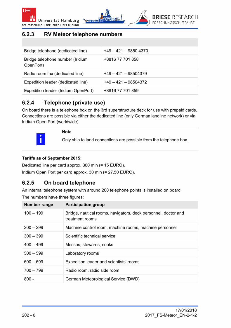
17/01/2018 202 - 6 2017_FS-Meteor_EN-2-1-2
6.2.3 RV Meteor telephone numbers
Bridge telephone (dedicated line) +49 – 421 – 9850 4370
Bridge telephone number (Iridium OpenPort)
+8816 77 701 858
Radio room fax (dedicated line) +49 – 421 – 98504379
Expedition leader (dedicated line) +49 – 421 – 98504372
Expedition leader (Iridium OpenPort) +8816 77 701 859
6.2.4 Telephone (private use) On board there is a telephone box on the 3rd superstructure deck for use with prepaid cards. Connections are possible via either the dedicated line (only German landline network) or via Iridium Open Port (worldwide).
Note
Only ship to land connections are possible from the telephone box.
Tariffs as of September 2015:
Dedicated line per card approx. 300 min (= 15 EURO).
Iridium Open Port per card approx. 30 min (= 27.50 EURO).
6.2.5 On board telephone An internal telephone system with around 200 telephone points is installed on board.
The numbers have three figures:
Number range Participation group
100 – 199 Bridge, nautical rooms, navigators, deck personnel, doctor and treatment rooms
200 – 299 Machine control room, machine rooms, machine personnel
300 – 399 Scientific technical service
400 – 499 Messes, stewards, cooks
500 – 599 Laboratory rooms
600 – 699 Expedition leader and scientists' rooms
700 – 799 Radio room, radio side room
800 - German Meteorological Service (DWD)

17/01/2018 2017_FS-Meteor_EN-2-1-2 6 - 203
6.3 Scientific intercom system The scientific intercom system serves to create up to three speech circuits on board which are independent of one another, one of which can always be selected.
On board there are 42 telephone points at user relevant locations.
On deck these are also equipped with pressure chamber loudspeakers. By selecting a speech circuit, it is possible to make a connection to one or more telephone points of the same circuit. Channel 3 is normally used for communication between the laboratories, the bridge and the winch consoles.
Selection of the speech circuit occurs by pressing a button on the operating appliance. The activation of the connection occurs by pressing the speech button on the handset.
6.4 E-mail An electronic mail system is present on the ship (DAVIS-mail, Software & Systems AG).
Each participant in the voyage is given a personal e-mail address, which can be used both officially and privately. The addresses are allocated on board by the systems manager (Sysman). For this purpose he receives a list of the scientists who will be joining the ship prior to departure.
Participation in the e-mail system includes agreement by the user to electronic storing of his e-mail in on board or on land systems for any verification obligations.
6.4.1 Personal e-mail address "1st letter of first [email protected]"e.g. for Hein Mück "[email protected]"
Personal addresses are limited to 500 kBytes per e-mail (incoming and outgoing).
For incoming e-mails (to *.*@meteor.briese-research.de) above the size limits, notification will take place via the mail system. The e-mail can then be released by the system manager on the instruction of the system manager.
6.4.2 Permanent e-mail addresses The following official addresses are available for sending/receiving large e-mails, which will be issued by the voyage leader:
[email protected] (limited to 2 MBytes)
[email protected] (limited to 2 MBytes)
[email protected] (limited to 2 MBytes)
[email protected] (limited to 2 MBytes)
The size limit can be increased accordingly by the Sysman (system administrator) for the transmission time if required.
If required and with the consent of the expedition leader, additional work addresses with a higher size limit of up to 2 MB can be set up temporarily.

17/01/2018 204 - 6 2017_FS-Meteor_EN-2-1-2
6.4.3 Accessibility of the ship The ship can be reached by e-mail at address [email protected]. The e-mails must be limited to a maximum of 2 MBytes!
6.5 Internet
6.5.1 PC with internet access If the dedicated line is available, the following computers are made available in subordinate order for free internet use with reference to telephone and e-mail:
Expedition leader
Master
German Meteorological Service
Sysman
1 public PC available for scientific use in the drawing room
1 public PC available for crew in ship's office 2nd superstructure deck
In principle the activation of the internet access is restricted to these PCs.
The sysman can if required clear further computers/laptops temporarily for internet use following assent of the expedition leader and master.
6.5.2 Internet use, bandwidth As the bandwidth is restricted, simultaneous internet use has an adverse effect on the general internet speed. The current bandwidth of 128 kbit/s will in no way allow "jerk free" surfing and downloading as it would on land.
If there is only Iridium OpenPort available, internet use will remain limited to the PC of the expedition manager for reasons of cost. If required, an additional internet connection can be made temporarily available by the system manager.
Note
The laws and stipulations regarding internet use (e.g. surfing on pages with illegal content or content which endangers young people) do of course also apply on board.
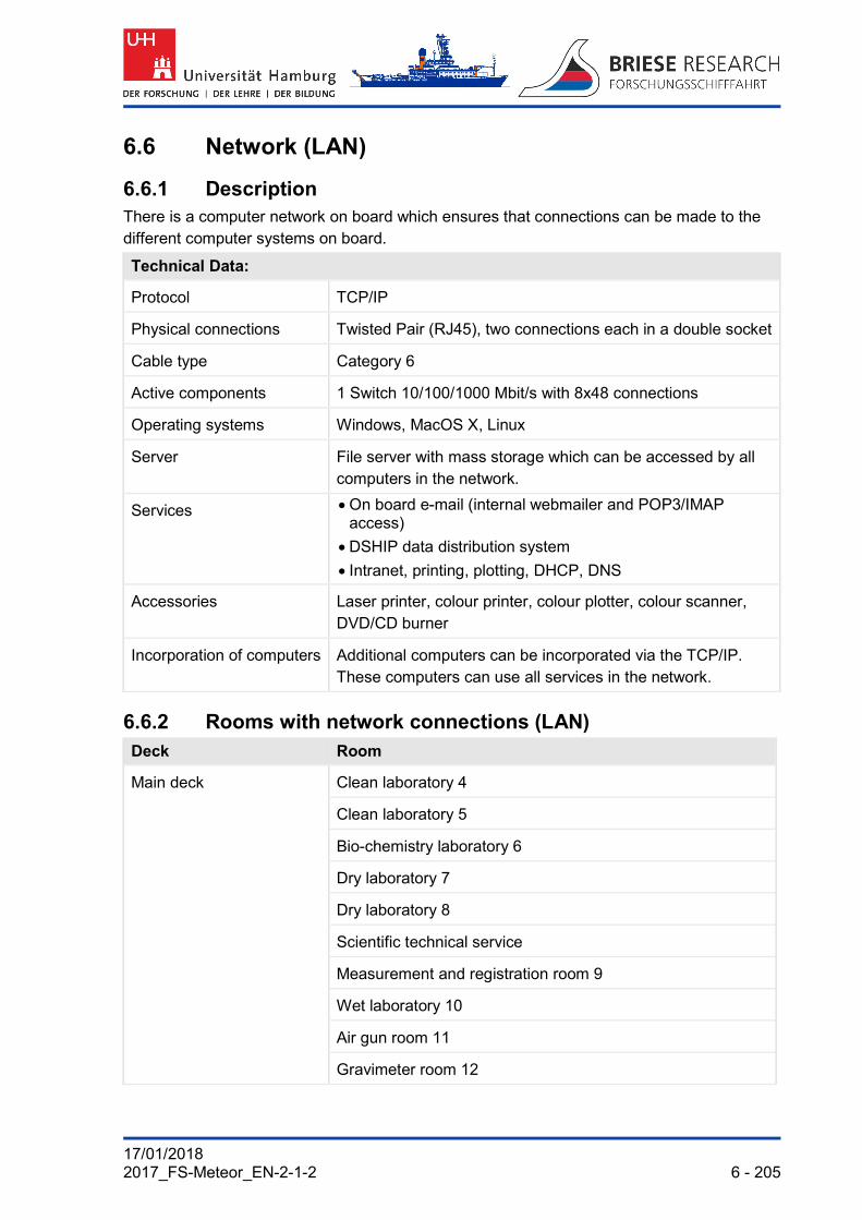
17/01/2018 2017_FS-Meteor_EN-2-1-2 6 - 205
6.6 Network (LAN)
6.6.1 Description There is a computer network on board which ensures that connections can be made to the different computer systems on board.
Technical Data:
Protocol TCP/IP
Physical connections Twisted Pair (RJ45), two connections each in a double socket
Cable type Category 6
Active components 1 Switch 10/100/1000 Mbit/s with 8x48 connections
Operating systems Windows, MacOS X, Linux
Server File server with mass storage which can be accessed by all computers in the network.
Services On board e-mail (internal webmailer and POP3/IMAP access)
DSHIP data distribution system
Intranet, printing, plotting, DHCP, DNS
Accessories Laser printer, colour printer, colour plotter, colour scanner, DVD/CD burner
Incorporation of computers Additional computers can be incorporated via the TCP/IP. These computers can use all services in the network.
6.6.2 Rooms with network connections (LAN) Deck Room
Main deck Clean laboratory 4
Clean laboratory 5
Bio-chemistry laboratory 6
Dry laboratory 7
Dry laboratory 8
Scientific technical service
Measurement and registration room 9
Wet laboratory 10
Air gun room 11
Gravimeter room 12

17/01/2018 206 - 6 2017_FS-Meteor_EN-2-1-2
Deck Room
Main deck Drawing room 13
Computer room 14
Universal laboratory 15
Geo laboratory 16
Filling room 17
Conference room
All rooms for scientists
Scientific stowage 1
Forecastle deck Treatment room
All rooms for crew
1st superstructure deck Machine office
All rooms for scientists and crew
2nd superstructure deck On board weather station
Ship's office
All rooms for scientists and crew
3rd superstructure deck Sounding centre 2
Radio room
4th superstructure deck Bridge
5th superstructure deck Air chemistry laboratory 1
Tween deck Machine control room (MKR)
Containers, further rooms Connection by loose laid network cables possible.
Note
Several connections are already taken up by recording computers and DSHIP display PCs with fixed installations.

17/01/2018 2017_FS-Meteor_EN-2-1-2 6 - 207
6.7 PC work stations
6.7.1 Scientific PC work stations Three PC work stations for scientific users are installed in the drawing room (main deck). The computers are connected to the other laboratory rooms via the network, meaning that data transfer with other computers is possible without problems.
The DSHIP display PCs installed in the laboratory rooms can also be used for normal PC applications.
Network connection standard: Ethernet connection 10/100/1000 Mbit/sec, TCP/IP
6.7.2 Software The PC workstations and DSHIP display PCs have the Windows 7™ or Windows10™ operating system as standard.
Most of the PCs also have Microsoft Office™ (Word, Excel etc.), scanner software and DVD/CD burner software.
User specific software which has been brought on board can be installed by the system manager if required and should be deleted again at the end of the expedition.

17/01/2018 208 - 6 2017_FS-Meteor_EN-2-1-2
6.8 DSHIP display PC DSHIP is based on the DAVIS™ measurement data management system and it represents a flexible system for the recording, processing, visualisation, distribution and archiving of marine measurement data.
6.8.1 Recording of data DSHIP is suitable for the recording of data of various instruments via standard interfaces like
NMEA 0183 / 2000,
IEEE 488,
networks.
6.8.2 Distribution of data DSHIP generates standard and user specific configured data telegrams and makes these available via various interfaces:
to configurable NMEA clients,
via serial interfaces,
via network interfaces.
6.8.3 Visualisation of data The visualisation of data occurs
through pre-configured standard displays,
through freely configurable displays,
o scale values
o graphs
o plots
in day/night mode,
in maps.
6.8.4 Storage of data Measurement data can be archived in various ways:
automatically online,
in configurable compression,
in compressed storage on board,
for later use on land.

17/01/2018 2017_FS-Meteor_EN-2-1-2 6 - 209
Fig. 133 Example of DSHIP display presentation

17/01/2018 210 - 6 2017_FS-Meteor_EN-2-1-2
6.8.5 Export of data The data export occurs web based in various formats:
as ASCII,
CSV or
Other.
Selection of export data according to
Date,
Time,
Sensor.
The data are available as an e-mail message or for offline processing.
6.8.6 Further features DSHIP works independently, is capable of multitasking and provides
Comfortable autonomy for automatic use, this allows
o Fitting of new sensors
o Configuration of available sensors
o Installation of back up and archiving modalities
Continuous monitoring,
Possibility of configuration before start of expedition,
Avoidance of inconsistent entries,
Scientific station book with
o Event and alarm treatment with classification of the events
o Position according to time and other data
o Listing of the use of appliances and events.

17/01/2018 2017_FS-Meteor_EN-2-1-2 6 - 211
6.9 Camera monitoring system 1 2 3
5 4 Fig. 134 Monitoring cameras 2 and 8, junction box in geo laboratory 16
1 Outrigger 4 Junction box in geo laboratory 16 2 Winch W3 5 Camera 8 at winch W12 3 Camera 2

17/01/2018 212 - 6 2017_FS-Meteor_EN-2-1-2
6.9.1 Description The camera monitoring system provides visual monitoring of the winches and the working deck.
The setting of the cameras and the operation occur through the ship's personnel (scientific technical service WTD) and the ship's personnel on the bridge.
In some of the laboratories connecting sockets for video monitors are available, onto which the images of cameras 1, 2 and 3 can be switched.
The connection is undertaken by WTD.
6.9.2 Cameras on RV Meteor
Camera Installation Monitoring area
1 horizontal/vertical can be pivoted with zoom
Rear gallows with linked deck area
2 horizontal/vertical can be pivoted with zoom
Rope outlet winches W1, W2, W3 with associated deck area
3 horizontal/vertical can be pivoted with zoom
Area under the movebar, winch W4 with associated deck area
4 fixed Storage winch W3 (11mm cable)
5 fixed Storage winch W2 (11mm cable)
6 fixed Friction winch W10
7 fixed Storage winch W11
8 fixed Storage winch W12

17/01/2018 2017_FS-Meteor_EN-2-1-2 7 - 213
7. LIFE ON BOARD 1 2
4 3
Fig. 135 Mess and bar
1 Buffet in the mess 3 Bar 2 Dining room 4 Counter in the bar

17/01/2018 214 - 7 2017_FS-Meteor_EN-2-1-2
Life on board the expedition vessel for the scientists is determined by various factors:
Accommodation in (double) cabins
Comprehensive, varied on board catering
Uniformity of daily routine (except for current experimentation phases), no customary passing of the week
Possibility of convivial and sporting activities during free time on board
Limited individual opportunities for withdrawal
Limited communication channels to mainland
Limited sharing in up to date media, politics and culture. E-newspaper “Die Welt” is available on the Meteor Intranet
Best possible incorporation into on board life
7.1 Cabins The accommodation of the scientists is usually in comfortable twin cabins with bunk beds on the mostly well attended expeditions.
Each room has a comfortably sized wet room (WC, shower and sink).
A table, couch and network connection are also available. Cupboard space is appropriate but not lavish.
Cabin Deck Number Cabin number
Twin cabins 1st superstructure deck
7 505, 511, 519, 525, 529, 535, 539
Twin cabins Main deck 6 718, 724, 726, 734, 736, 742
Single cabins 1st superstructure deck
2 543 (Senior scientist)
552 (Meteorologist)
Single cabins 2nd superstructure deck
2 433 (Voyage leader)
420 (Weather radio engineer)

17/01/2018 2017_FS-Meteor_EN-2-1-2 7 - 215
1
3 2
Fig. 136 Free time opportunities
1 Sports equipment in fitness room 2 Sports equipment in scientific stowage 1 3 Seat on rear forecastle deck

17/01/2018 216 - 7 2017_FS-Meteor_EN-2-1-2
7.2 Food The catering for the expedition participants is done in the on board kitchen in the mess in the middle deck port front.
7.3 Sale of canteen goods The steward is responsible for the sale of canteen goods.
Please speak to the steward regarding sales times.
A card reader for cashless payments is present on board, which takes EC cards and the most popular credit cards.
7.4 On board laundry A laundry is present on board in which any washing can be processed on request.
The on board laundry is located on the main deck port side next to the front scientific stowage 1.
A washing machine and drier are available for scientists who are travelling in the front of the forecastle deck. The washing powder is available on board.
7.5 General rules of conduct
Note
No waste or other objects may be thrown from the ship!
7.5.1 Safety At the start of each expedition the safety officer conducts a comprehensive safety lecture.
Safety instructions are placed on the inside of all doors of rooms. These must be read carefully by each participant in the expedition.
Please memorise the following two types of alarm:
General alarm 7 short tones and 1 long
tone in succession
Leaving the ship 1 short and 1 long tone in
succession (repeated continuously)

17/01/2018 2017_FS-Meteor_EN-2-1-2 7 - 217
7.5.2 Health The following documents must be brought along regardless of the area of the expedition:
Blood group notification or emergency ID
Allergy notification (if present and necessary)
Vaccination certificate Vaccination certificates are required by the port health authorities of many countries.
Medication taken regularly in sufficient quantity. The stocks of the on-board pharmacy only cover emergency and standard medication.
7.5.3 Battery supply Watch, camera and other important batteries are of course at the end of their life cycle during a research expedition. Even if various types of battery are available on board, there cannot be any guarantee that the right type is available. For this reason it is absolutely necessary that replacement batteries are brought for appliances which the expedition participant brings on board!
7.5.4 Glasses Glasses are sensitive. They can only be repaired on board in exceptional cases. You must bring a replacement pair with you. Remember your sunglasses as well!
7.5.5 Table tennis There is a table tennis table on board which can be set up in the scientific stowage areas 1 and 2 in good weather and when there is sufficient space available.
If you like to use your own bat, you will need to bring it with you!
7.5.6 Room doors Room doors should remain open at sea if nobody is in the room. The stewards can then carry out cleaning without anyone having to be present or disturbed.
7.6 Waste disposal
7.6.1 Waste separation Separate containers in the living and laboratory area are put in place for glass and metal waste and also for waste which can be incinerated.
The waste containers in the living rooms may only be used for waste which can be incinerated.
7.6.2 Packaging When packing scientific equipment, you are asked to use materials which can easily be reduced to small pieces and burnt with low pollution.

17/01/2018 218 - 7 2017_FS-Meteor_EN-2-1-2
7.6.3 Used batteries Used batteries and old rechargeable batteries are collected on board and disposed of in accordance with the national regulations.
7.6.4 Residual waste Combustible waste is disposed of by means of a shredder and a waste incinerator.
Rubbish which cannot be or may not be shredded and incinerated is collected and disposed of properly on shore.

17/01/2018 2017_FS-Meteor_EN-2-1-2 7 - 219
7.6.5 Chemicals
Fig. 137 Chemical store
During the voyage, chemicals will be kept in the chemical store, which is on the working deck next to the stairs to the forecastle deck.
The store has an area of 2.44 m x 0.97 m and a height of 2.33 m.
It is equipped with two racks, each of which has five shelves (height per compartment 41 cm, depth 45 cm):
Shelf 1 [W x H]: 1.75 m x 1.80 m,
Shelf 2 [W x H]: 0.81 m x 1.80 m.
At the end of the trip, all chemicals must be removed from the ship and the chemical store handed over to the 1st officer broom-clean.
The disposal of solid and liquid chemicals must occur in a technically correct manner, with return transport where necessary.
With larger quantities the following must be taken into account:
Collect chemicals separately in plastic containers while taking the IMDG regulations into account
Mark containers clearly with contents while taking the IMDG regulations into account
Return transport is performed by the user together with the scientific equipment
The following documents are required:
Safety data sheet for each substance (reference via the manufacturer)
Certification concerning hazardous goods (responsible declaration)
Container packing certificate
Labelling with IMDG label:
Container marking: 4 large labels
Container marking: 2 small labels

17/01/2018 220 - 7 2017_FS-Meteor_EN-2-1-2
List of illustrations: Fig. 1 Research vessel METEOR ................................................................................................................... 3-13 Fig. 2 RV METEOR, deck arrangement, scientific storage space, propulsion and aids to manoeuvring ........ 3-14 Fig. 3 RV METEOR, 6th and 5th superstructure deck .................................................................................... 3-16 Fig. 4 RV METEOR, 4th and 3rd superstructure deck .................................................................................... 3-18 Fig. 5 RV METEOR, 2nd superstructure deck ................................................................................................ 3-20 Fig. 6 RV METEOR, 1st superstructure deck ................................................................................................. 3-22 Fig. 7 RV METEOR, forecastle deck .............................................................................................................. 3-24 Fig. 8 RV METEOR, main deck with scientific working areas and living areas ............................................... 3-26 Fig. 9 RV METEOR, tween deck .................................................................................................................... 3-28 Fig. 10 RV METEOR, storage .......................................................................................................................... 3-30 Fig. 11 RV METEOR, raised floor with sensors ................................................................................................ 3-32 Fig. 12 RV METEOR, arrangement of connecting staircases inside the ship ................................................... 3-34 Fig. 13 RV METEOR, deck cranes and lifting apparatus with working area ..................................................... 3-36 Fig. 14 RV METEOR, outrigger with winch arrangement and cable guide ....................................................... 3-38 Fig. 15 RV METEOR, movebar ........................................................................................................................ 3-40 Fig. 16 RV METEOR, rear gallows ................................................................................................................... 3-42 Fig. 17 RV METEOR, crane on the foredeck (provision crane) ........................................................................ 3-44 Fig. 18 RV METEOR, crane on 5th superstructure deck .................................................................................. 3-46 Fig. 19 RV METEOR, winch arrangement and cable guide (without mobile or container winches) .................. 3-49 Fig. 20 RV METEOR, container spaces ........................................................................................................... 3-50 Fig. 21 RV METEOR, storage plan .................................................................................................................. 3-52 Fig. 22 RV METEOR, deck socket grid ............................................................................................................ 3-54 Fig. 23 RV METEOR, deck sockets of built-over rear float ............................................................................... 3-55 Fig. 24 RV METEOR, scientific storage areas I and IV .................................................................................... 3-56 Fig. 25 RV METEOR, scientific storage areas II and III .................................................................................... 3-58 Fig. 26 RV METEOR, Communication antennae ............................................................................................. 3-60 Fig. 27 RV METEOR, navigation antennae ...................................................................................................... 3-62 Fig. 28 RV METEOR, antennae and sensors used for meteorological purposes ............................................. 3-64 Fig. 29 RV METEOR, escape routes to assembly point and rescue boat ........................................................ 3-66 Fig. 30 Rescue resources .............................................................................................................................. 3-67 Fig. 31 Equipment details for the laboratory and workrooms ......................................................................... 4-68 Fig. 32 Air chemistry laboratory 1 .................................................................................................................. 4-70 Fig. 33 Air chemistry laboratory 1, Gonio radio direction finder ..................................................................... 4-71 Fig. 34 Air chemistry laboratory 1 .................................................................................................................. 4-72 Fig. 35 Air chemistry laboratory 1 (detailed plan laboratory walls, status 1986) ............................................ 4-73 Fig. 36 Sounding centre 2 .............................................................................................................................. 4-74 Fig. 37 Sounding laboratory 2 (detailed plan laboratory walls, status 1986) .................................................. 4-75 Fig. 38 Darkroom 3 ........................................................................................................................................ 4-76 Fig. 39 Darkroom area of dark room 3 (detailed plan laboratory walls, status 1986) .................................... 4-77 Fig. 40 Clean laboratory 4 with double door .................................................................................................. 4-78 Fig. 41 Clean laboratory 4 with double door .................................................................................................. 4-79 Fig. 42 Detailed plan of clean laboratory 4 with double door ......................................................................... 4-80 Fig. 43 Clean laboratory 4 (detailed plan laboratory walls, status 1986) ....................................................... 4-81 Fig. 44 Clean laboratory 5 ............................................................................................................................. 4-82 Fig. 45 Clean laboratory 5 ............................................................................................................................. 4-83 Fig. 46 Clean laboratory 5 ............................................................................................................................. 4-84 Fig. 47 Clean laboratory 5 (detailed plan laboratory walls, status 1986) ....................................................... 4-85 Fig. 48 Bio-chemistry laboratory 6 ................................................................................................................. 4-86 Fig. 49 Bio-chemistry laboratory 6 ................................................................................................................. 4-87 Fig. 50 Bio-chemistry laboratory 6 ................................................................................................................. 4-88 Fig. 51 Bio-chemistry laboratory 6 (detailed plan laboratory walls, status 1986) ........................................... 4-89 Fig. 52 Dry laboratory 7 ................................................................................................................................. 4-90 Fig. 53 Dry laboratory 7 ................................................................................................................................. 4-91 Fig. 54 Dry laboratory 7 ................................................................................................................................. 4-92 Fig. 55 Dry laboratory 7 (detailed plan laboratory walls, status 1986) ........................................................... 4-93 Fig. 56 Dry laboratory 8 ................................................................................................................................. 4-94 Fig. 57 Dry laboratory 8 ................................................................................................................................. 4-95 Fig. 58 Dry laboratory 8 ................................................................................................................................. 4-96 Fig. 59 Dry laboratory 8 (detailed plan laboratory walls, status 1986) ........................................................... 4-97 Fig. 60 Measurement and registration room 9 ............................................................................................... 4-98 Fig. 61 Measurement and registration room 9 ............................................................................................... 4-99 Fig. 62 Measurement and registration room 9 ............................................................................................. 4-100 Fig. 63 Measurement and registration room 9 (detailed plan, status 1986) ................................................. 4-101 Fig. 64 Wet laboratory 10 ............................................................................................................................ 4-102 Fig. 65 Wet laboratory 10 ............................................................................................................................ 4-103 Fig. 66 Wet laboratory 10 ............................................................................................................................ 4-104

17/01/2018 2017_FS-Meteor_EN-2-1-2 7 - 221
Fig. 67 Wet laboratory 10 (detailed plan laboratory walls, status 1986) ...................................................... 4-105 Fig. 68 Air gun room 11 ............................................................................................................................... 4-106 Fig. 69 Filling station for air guns ................................................................................................................. 4-107 Fig. 70 Gravimeter room 12......................................................................................................................... 4-108 Fig. 71 Gravimeter room 12 (detailed plan of laboratory walls, version 1986) ............................................. 4-109 Fig. 72 Drawing room 13 ............................................................................................................................. 4-110 Fig. 73 Drawing room 13 ............................................................................................................................. 4-111 Fig. 74 Drawing room 13 (detailed plan of laboratory walls, version 1986) ................................................. 4-112 Fig. 75 Drawing room 13 (detailed plan of laboratory walls, version 1986) ................................................. 4-113 Fig. 76 Universal laboratory 15 .................................................................................................................... 4-114 Fig. 77 Universal laboratory 15 .................................................................................................................... 4-115 Fig. 78 Universal laboratory 15 .................................................................................................................... 4-116 Fig. 79 Universal laboratory 15 (detailed plan of laboratory walls, version 1986) ........................................ 4-117 Fig. 80 Geo laboratory 16 ............................................................................................................................ 4-118 Fig. 81 Geo laboratory 16 ............................................................................................................................ 4-119 Fig. 82 Geo laboratory 16 ............................................................................................................................ 4-120 Fig. 83 Geo laboratory 16 ............................................................................................................................ 4-121 Fig. 84 Filling room 17 ................................................................................................................................. 4-122 Fig. 85 Filling room 17 ................................................................................................................................. 4-123 Fig. 86 Filling room 17 (detailed plan laboratory walls, status 1986) ........................................................... 4-124 Fig. 87 Filling room 17 (detailed plan laboratory walls, status 1986) ........................................................... 4-125 Fig. 88 Measurement and sounding room 18 .............................................................................................. 4-126 Fig. 89 Thermosalinograph in ground measurement room below measuring and sounding room 18 ......... 4-127 Fig. 90 Air conditioned laboratory unit 19 .................................................................................................... 4-128 Fig. 91 Air conditioned laboratories and refrigeration room: Laboratory and measuring room .................... 4-129 Fig. 92 Air conditioned laboratory unit: Aquarium cold room (photo), laboratory and
measuring room (plan) .................................................................................................................... 4-130 Fig. 93 Aquarium refrigeration room (detailed plan laboratory walls, status 1986) ...................................... 4-131 Fig. 94 Brigde .............................................................................................................................................. 4-132 Fig. 95 Bridge .............................................................................................................................................. 4-133 Fig. 96 (DWD) container with balloon ascent .............................................................................................. 4-134 Fig. 97 DWD weather service ...................................................................................................................... 4-136 Fig. 98 Conference room ............................................................................................................................. 4-138 Fig. 99 Conference room ............................................................................................................................. 4-139 Fig. 100 Library ............................................................................................................................................. 4-140 Fig. 101 Library ............................................................................................................................................. 4-141 Fig. 102 Echo sounder KONGSBERG EM 710 and EM 122 ......................................................................... 5-142 Fig. 103 Echo sounders KONGSBERG EM 710 and EM 122 ....................................................................... 5-144 Fig. 104 Screen presentation on echo sounder KONGSBERG EM 710 ....................................................... 5-146 Fig. 105 Appliance chart "Parasound P70".................................................................................................... 5-148 Fig. 106 Screen presentation sediment echo "Parasound" ........................................................................... 5-150 Fig. 107 ELAC LAZ 5100 and repeater display DAZ 25 ................................................................................ 5-152 Fig. 108 ADCP .............................................................................................................................................. 5-154 Fig. 109 Position sensor MRU 5 in the machine workshop ........................................................................... 5-156 Fig. 110 Seapath system ............................................................................................................................... 5-158 Fig. 111 SAM 4683 Doppler log (2-axis) ....................................................................................................... 5-160 Fig. 112 Way of operation of the Posidonia appliance .................................................................................. 5-162 Fig. 113 C-Navigator, RhoTheta 300 radio direction finder ........................................................................... 5-164 Fig. 114 RhoTheta 300 radio direction finder, Gonio radio direction finder ................................................... 5-166 Fig. 115 GPS position sensor ........................................................................................................................ 5-168 Fig. 116 Navigat 2100, compass displays ..................................................................................................... 5-170 Fig. 117 Transmit / receive characteristic transducer ITC–3013, triggering unit IXSEA TT-801 .................... 5-172 Fig. 118 Deep freezer .................................................................................................................................... 5-173 Fig. 119 Thermosalinograph, temperature sensor SBE 38 ........................................................................... 5-174 Fig. 120 Thermosalinograph, temperature sensor SBE 38 ........................................................................... 5-175 Fig. 121 Sounding shaft, sounding shaft basket and adapter plate ............................................................... 5-177 Fig. 122 Core stacking frame ........................................................................................................................ 5-179 Fig. 123 CTD probe and water carousel ........................................................................................................ 5-181 Fig. 124 Radiation protection container ......................................................................................................... 5-183 Fig. 125 View of inside of radiation protection container ............................................................................... 5-185 Fig. 126 MeBo launching arrangement ......................................................................................................... 5-187 Fig. 127 Nitrogen generator........................................................................................................................... 5-189 Fig. 128 Milli-Q ultra-pure water system ........................................................................................................ 5-191 Fig. 129 Container cable winches in standard set up (series operation) ....................................................... 5-193 Fig. 130 Container winches F and S ............................................................................................................. 5-195 Fig. 131 Working boat METEORIT ................................................................................................................... 5-197 Fig. 132 Working boat (inflatable boat) .......................................................................................................... 5-199 Fig. 133 Example of DSHIP display presentation .......................................................................................... 6-209

17/01/2018 222 - 7 2017_FS-Meteor_EN-2-1-2
Fig. 134 Monitoring cameras 2 and 8, junction box in geo laboratory 16 ....................................................... 6-211 Fig. 135 Mess and bar ................................................................................................................................... 7-213 Fig. 136 Free time opportunities .................................................................................................................... 7-215 Fig. 137 Chemical store ................................................................................................................................. 7-219