2009 Expedition SSV Modifiers Guide, 09/2008
73
EXPEDITION EXPEDITION EL MODIFIERS GUIDE SPECIAL SERVICE VEHICLE (SSV) FCS-15102-09 2009 2009
-
Upload
khangminh22 -
Category
Documents
-
view
4 -
download
0
Transcript of 2009 Expedition SSV Modifiers Guide, 09/2008

EXPEDITION
EXPEDITION EL
MODIFIERS GUIDESPECIAL SERVICE VEHICLE (SSV)
FCS-15102-09
20092009

TABLEOF
CONTENTS
1 General Information
2 Electrical
3 Installation Considerations
4 Cargo Mounting Considerations
5 Reference Information
INTRODUCTION
SECTIONS
NOTE: The descriptions and specifications contained in this manual were in effect at the time this manual was approved for printing. Ford Motor Company reserves the right to discontinue models at any time, or change specifications or design without notice and without incurring any obligation.
All rights reserved. Reproduction by any means, elec tron ic or me chan i cal, in clud ing pho to copy ing, recording, or by any in for ma tion storage and re triev al system or trans la tion in whole or part is not per mit ted without writ ten au tho ri za tion from Ford Mo tor Company.
Copyright © 2008, Ford Motor Company

SECTION 0
Introduction
Contents
Introduction.......................................................................................0-1
2009 Expedition SSV Modifiers Guide, 09/2008

Introduction 0-1
Introduction
Ford Motor Company has assembled this Expedition Special Service Vehicle (SSV) ModifiersGuide to assist vehicle modifiers in producing safe and quality products. Ford believes that safetyand quality come first.
This book is divided into topics pertinent to modifiers of vehicles. Reference is made to the currentFord Expedition Workshop Manual for appropriate service procedures, torque specifications,component separation clearances and other standard information that is common with theunmodified vehicle. Specifications that are unique to the guide are designated.
This modifier guide is not a ‘‘how-to’’ book; it should be used as a checklist to help make sure thatcertain important steps in the modification process are considered. While Ford is providing thisinformation to assist modifiers, it does not warrant the products, methods, materials or theworkmanship of the modifier. Nor does it warrant against failures that result from the modificationof a vehicle.
Following the guidelines contained in this guide does not assure individual modifiers that theproducts they modify comply with U.S. Federal or Canadian Motor Vehicle Safety Standards ineffect at the time of the modification. The guidelines set forth are based on engineering analysesof typical vehicles. If followed, the modifier’s efforts in certifying vehicles to applicable standardsshould be aided. Compliance testing that may be required for certification of specific vehicleconfigurations or construction is, however, the sole responsibility of the individual modifier.
2009 Expedition SSV Modifiers Guide, 09/2008

SECTION 1
General Information
Contents
Section 1: General Information ........................................................1-1
Important Safety Notice................................................................1-1
Warnings, Notices and Notes ...................................................1-1
Making Safety Devices and Elements Inoperative...................1-2
Special Service Vehicle (SSV) Definition.....................................1-3
Identification Codes ......................................................................1-5
Good Practices .............................................................................1-9
Process and Quality Assurance Systems ................................1-9
Quality Assurance.....................................................................1-9
Minimum and Maximum Screw Sizes ......................................1-9
New Vehicle Storage....................................................................1-9
Tire Pressure Monitoring System (TPMS) Principles ofOperation ..................................................................................1-11
Ambient Temperature Change and Tire Pressure.....................1-12
2009 Expedition SSV Modifiers Guide, 09/2008

General Information 1-1
Section 1: General Information
Important Safety Notice
Note: The descriptions and specifications contained in this guide were in effect at the time thismanual was approved for printing. Ford Motor Company reserves the right to discontinuemodels at any time, or change specifications or design without notice and without incurringobligation.
Appropriate repair methods and procedures are essential for the safe, reliable operation of allmotor vehicles as well as the personal safety of the individual doing the work. This manualprovides general directions and guidelines for performing modifications to the Expedition SpecialService Vehicle (SSV). Following them will help assure reliability.
There are numerous variations in procedures, techniques, tools and parts for modifying vehicles,as well as in the skill of the individual doing the work. This manual cannot possibly anticipate allsuch variations and provide advice or cautions as to each. Accordingly, anyone who departs fromthe instructions provided in this manual must first establish that he compromises neither hispersonal safety nor the vehicle integrity by his choice of methods, tools or parts.
Warnings, Notices and Notes
As you read through this guide, you will come across WARNINGS, NOTICES and NOTES. Eachone is there for a specific purpose. WARNINGS remind you to be especially careful in those areaswhere carelessness can cause you personal injury. NOTICES are given to prevent you frommaking an error that could damage the vehicle. NOTES give you added information that will helpyou to complete a particular procedure.
2009 Expedition SSV Modifiers Guide, 09/2008

1-2 General Information
Section 1: General Information
The following list contains some general warnings that you should follow when you work on avehicle.
WARNING:
• Always wear safety glasses for eye protection.
• Use safety stands whenever a procedure requires you to be under the vehicle.
• Make sure that the ignition switch is always in the OFF position, unless otherwiserequired by the procedure.
• Set the parking brake when working on the vehicle. The gear selector should be set inPARK unless instructed otherwise for a specific operation. Place wood blocks (4 in x 4 inor larger) against the front and rear surfaces of the tires to help prevent the vehicle frommoving.
• Operate the engine only in a well-ventilated area to avoid the danger of carbon monoxidepoisoning.
• Keep yourself and your clothing away from moving parts when the engine is running,especially the drive belts.
• To reduce the risk of serious burns, avoid contact with hot metal parts such as theradiator, exhaust manifold, tailpipe, catalytic converter and muffler.
• Do not smoke while working on a vehicle.
• To reduce the risk of injury, always remove rings, watches, loose hanging jewelry andloose clothing before beginning to work on a vehicle.
• When it is necessary to work under the hood, keep hands and other objects clear of theradiator fan blades.
• Failure to follow these instructions may result in personal injury.
Making Safety Devices and Elements Inoperative
The vehicle contains many safety features required by Federal or Canadian Motor Vehicle SafetyStandards. These features, which include the key-in-ignition chime and brake lights, should neverbe disabled or modified.
Section 30122 of 49 USC states that ‘‘A manufacturer, distributor, dealer or motor vehicle repairbusiness may not knowingly make inoperative any part of a device or element of design installedon or in a motor vehicle or motor vehicle equipment in compliance with an applicable motor vehiclesafety standard prescribed under this chapter unless the manufacturer, distributor, dealer or repairbusiness reasonably believes the vehicle or equipment will not be used (except for testing or asimilar purpose during maintenance or repair) when the device or element is inoperative.’’
2009 Expedition SSV Modifiers Guide, 09/2008

General Information 1-3
Section 1: General Information
Special Service Vehicle (SSV) Definition
Special Service Vehicles (SSV) are offered to fill the special needs of police agencies that astandard patrol car can not.
SSV Standard Package Deletes
Item
Floor consoleFloor matsFog lamps
Third-row seat
Standard Equipment
System Description
Powertrain/Functional 5.4L SOHC 3V V8 Engine6-speed automatic O/D transmissionNon-limited slip axle (3.73 ratio)Multi-link independent rear suspensionP265/70R17 BSW A/S tires (4x2 only)P265/70R17 OWL ON/OFF road tires (4x4 only)Front skid plates only (4x2)Front, transfer case and gas tank skid plates (4x4 only)Tire pressure monitoring system (TPMS)Variable assist power rack and pinion steering
Exterior 17-in Steel wheels (Expedition only)17-in Aluminum wheels (Expedition EL only)AutolampsBody-color body-side cladding, front/rear fascia and wheel lip moldingsBlack door handlesFog lampsBlack grilleDual beam complex reflector headlampsKeyless entry keypadBlack, heated power mirrors with security approach lampsPrivacy glassRemote keyless entry with 2 key fobs (4 buttons each)Black roof railsStep bars (4x2 only)Tow hooks (4x4 only)Trailer towing — integrated class III receiver with 4-pin connector
(Continued)
2009 Expedition SSV Modifiers Guide, 09/2008

1-4 General Information
Section 1: General Information
Standard Equipment
System Description
Interior Second and third row coat hooksSecond row map lightsManual A/C with auxiliary climate controlsAM/FM single CD, 6-premium speakers (160-watts peak), driver adjusted speedcompensated volume, partitioned audio, rear seat controls and MP3 capabilityColor-keyed assist handlesAuxiliary audio input jack in instrument panelCargo organizer (Expedition EL only)Column shifterDome lightVinyl floor coveringVinyl jack stowage coverElectrochromatic day/night auto-dimming rearwiew mirrorOverhead console with map lights, single sunglasses holder and conversation mirrorPower door locks and windows with one-touch DOWN driver side windowFirst row low back cloth captain’s chairs with 2-way adjustable headrests, 6-waypower driver with power lumbar, passenger manual reclineSecond row vinyl 40/20/40 seats without armrest or cupholderColor-keyed, leather-wrapped steering wheel with tilt and speed control switchesSunvisors with dual auxiliary blades and illuminated mirrors
Safety/Security AdvanceTrac with Roll Stability Control (RSC)Driver and passenger passive restraint air bagsRear door child safety locksLower anchors and tethers for children system in rear outboard seatsPower disc brakes with 4-wheel anti-lock system and brake assistPersonal safety systemPerimeter alarmSafety CanopySide intrusion door beamsSide thorax air bagsSecurilock passive anti-theft system (PATS)S.O.S. post-crash alert
Miscellaneous Options (See sales brochure for complete list of available options)
Item Description
XLT Comfort Group (52C) Overhead console with map lights, sunglasses holder, front auxiliary climate controlsand conversation mirrorSecond row map lightsIlluminated visor vanity mirrors
Convenience Package (50C) Power-adjustable pedals(requires XLT Comfort Power rear quarter windows
Group) Universal garage door openerReverse sensing system
Heavy-Duty Trailer Tow Class IV hitch receiverPackage (536) Four- and 7-pin connectors
Heavy-duty auxiliary transmission oil cooler and radiatorElectronic brake wiring kit
Technical Package (17T) Auto-dimming rearview mirror(requires XLT Comfort Keyless-enty keypad
Group) Heated sideview mirrors(Continued)
2009 Expedition SSV Modifiers Guide, 09/2008

General Information 1-5
Section 1: General Information
Miscellaneous Options (See sales brochure for complete list of available options)
Item Description
Exterior Options Daytime running lamps (43D)Engine block heater (41H)Heated sideview mirrors (54H)Running boards (4x4 only) (186)
Seat Options First row 40/60 split bench cloth with power adjustable driver’s seat (M)Second row 40/20/40 split bench cloth (N/A with 875 third row seat) (21F)Second and third row bench cloth (requires 574 rear aux A/C and heat)1 (21S)Third row 60/40 split bench vinyl (requires 574 rear aux A/C and heat)2 (875)
Identification Codes
Vehicle Certification (VC) Label
The upper portion of the vehicle certification (VC) label contains the manufacturer name, themonth and year of manufacture, the certification statement and the vehicle identification number(VIN). It also includes the gross vehicle weight rating (GVWR) and the gross axle weight rating(GAWR), as well as tire size and pressure ratings. The VC label is located on the left-hand frontdoor edge.
1, 2 Standard on EL SSV
2009 Expedition SSV Modifiers Guide, 09/2008

1-6 General Information
Section 1: General Information
Vehicle Certification (VC) Label Code Positions
Position Description
1 Exterior paint code
2 Region code
3 District Special Order(DSO)
4 Wheelbase code
5 Interior trim code
6 Tape/paint pinstripe code
7 Radio code
8 Axle code
9 Transmission code
10 Spring code
11 Powertrain calibrationinformation
2009 Expedition SSV Modifiers Guide, 09/2008

General Information 1-7
Section 1: General Information
1. Exterior Paint Color Code
The first set of numbers/letters listed indicate the vehicle primary body color code. The second setof letters/numbers listed (if applicable) indicate a 2-tone or accent body color code.
• DX — Dark Blue Pearl
• HS — Stone Green
• JV — Sangria Red
• T9 — Black Pearl Slate
• UA — Ebony
• UG — White Platinum
• UK — Royal Red
• YZ — Oxford Red
• ZY — Vapor Silver Pearl
4. Wheelbase Code
• 119 — 3,023 mm (119 in) wheelbase
• 131 — 3,327 mm (131 in) wheelbase
5. Interior Trim Code
The interior trim colors are:
Trim Type
• 1 — Verona leather (2-tone), 40/40 Captain’s chairs — Expedition
• 2 — Verona leather, 40/40 Captain’s chairs — Expedition
• 3 — Verona leather, 40/40 Captain’s chairs with accent — Expedition
• 4 — Verona leather, Eddie Bauer — Expedition
• 5 — Aniline leather (perforated), King Ranch — Expedition
• F — Cloth Captain’s chair — Expedition
• M — Cloth 40/60 split bench seat — Expedition
• T — Premium/Soho leather, 40/60 Captain’s chairs — Navigator
2009 Expedition SSV Modifiers Guide, 09/2008

1-8 General Information
Section 1: General Information
Interior Trim Color
• C — Camel Tan
• L — Medium Light Stone
• W — Charcoal Black
7. Radio Type
• 1 — AM/FM stereo with in-dash, 6-disc CD changer and clock
• F — AM/FM stereo CD player, navigation system and clock
• S — Premium electric AM/FM stereo CD player
• T — Premium AM/FM stereo with in-dash CD changer and clock
• U — Premium AM/FM stereo with in-dash, 6-disc CD changer and THX speaker System
• X — AM/FM stereo with in-dash, CD changer and navigation system
8. Axle Ratio Code
The axle ratios are:
• 15 — 3.31 ratio, non-limited slip
• 16 — 3.73 ratio, non-limited slip
• H6 — 3.73 ratio, limited slip
10. Spring Code
Front Springs
• AA — 5L14-3C-098-AB
• BB — 5L14-3C098-BB
• CC — 3L1J-18B036-AA
• DD — 5L74-3C098-AC
• FF — 3L14-18B036-BA
• HH — 3L14-18B036DA
Rear Springs
• 11 — 4L14-18W00-AA
• 33 — 5L14-5A965-BB
2009 Expedition SSV Modifiers Guide, 09/2008

General Information 1-9
Section 1: General Information
• 44 — 5L14-5A965-AB
• 55 — 4L1J-18W002-AA
• 66 — 5L74-5A965-AB
11. Powertrain Calibration Information
Powertrain calibration information is printed in the lower right corner of the VC label. Only the basecalibration information is printed. Revision levels will not appear. Powertrain calibration informationis limited to a maximum of 5 characters per line on the VC label. Calibration identificationconsisting of more than 5 characters will wrap to the second line on the VC label.
Good Practices
Process and Quality Assurance Systems
A formalized Process and Quality Assurance system may be helpful in consistently producinghigh-quality products. An overview of some of the key items for such a system are outlined in thissection.
Quality Assurance
Completed Unit Sign-Off: All control items should be inspected with a written sign-off. All labelsshould be inspected and signed off, including verification that the information on the labels iscorrect. All appropriate systems should be checked for leaks. A road test should be performed toverify that all systems are operating correctly. All systems and functions that were provided byFord should be checked to make sure that they function correctly after the build process.
The modifier’s Process and Quality Assurance Systems should also make sure that appropriatetraining is provided to the employees.
Minimum and Maximum Screw Sizes
When installing aftermarket equipment, avoid using fasteners that are too long for the applicationor are in an area which might damage vehicle components, including wiring, brake lines, fuel tankand lines, powertrain components, exhaust system and suspension. Details for mountingequipment in the trunk, as well as appropriate fasteners, can be found in Section 4, CargoMounting Considerations.
New Vehicle Storage
New Vehicle Storage — General
• Vehicles should be stored in a dry, ventilated place, and protected from sunlight, if possible.
• If vehicles are stored outside, maintenance against rust and damage, as described below, isrecommended.
2009 Expedition SSV Modifiers Guide, 09/2008

1-10 General Information
Section 1: General Information
NOTICE: Keep all rubber parts free from oil and solvents. Damage to rubber parts canoccur.
New Vehicle Storage — Body
• Wash vehicle thoroughly to remove dirt, grease, oil, tar or mud from exterior surfaces andunderside of front fender.
• Periodically wash vehicles stored in exposed locations.
• Touch up exposed raw or primed metal to provide rust protection.
• Cover chrome and stainless steel parts with a thick coat of auto wax to prevent discoloration.Rewax as necessary when the vehicle is washed.
• Lubricate all hood, door hinges and latches with a light grade oil.
• Cover the interior soft trim to prevent fading.
New Vehicle Storage — Engine
• Start the engine every 15 days. Run it at fast idle until it reaches normal operating temperature.
• With foot on brake pedal (and brake applied), shift the transmission into all gears while theengine is running.
New Vehicle Storage — Fuel System
• Regularly move vehicles short distances to mix fuel anti-oxidation agents.
NOTICE: During extended periods of vehicle storage (60 days or more), gasoline maydeteriorate due to oxidation. This can damage rubber and other polymers in the fuel systemand may clog small orifices. A commercially available gasoline fuel stabilizer (Sta-Bil orequivalent) should be added to gasoline-powered vehicles whenever actual or expectedstorage periods exceed 60 days. The manufacturer’s instructions packaged with the productshould be followed. The vehicle should then be operated at an idle speed to circulate theadditive throughout the fuel system.
New Vehicle Storage — Tires
Most high-performance tires are made with nylon overlay.
2009 Expedition SSV Modifiers Guide, 09/2008

General Information 1-11
Section 1: General Information
As such, the following steps should be taken to avoid flat spotting when the vehicles are not usedfor a period of time.
• Store the vehicles with 44 psi in the tires. If the cars are to be driven, the air pressure should bereduced to recommended operating pressure and then increased back up to 44 psi whenreturned to storage.
• If the vehicle is stored for periods longer than 30 days, it should be moved several feet at leastonce during each 30-day period, so that a different portion of the tread contacts the ground.
Tire Pressure Monitoring System (TPMS) Principles of Operation
The tire pressure monitoring system (TPMS) monitors the air pressure of all 4 regular road tires.The tire pressure sensors, attached to each rim by a metal band located in the drop well, transmitvia a 315 Mhz radio frequency signal to the internal antenna of the smart junction box (SJB).These transmissions are sent approximately every 60 seconds when the vehicle speed exceeds32 km/h (20 mph). The SJB compares the tire pressure data against a low-pressure limit. If themodule determines that the tire pressure has fallen below this limit, the module communicates thison the vehicle network to the instrument cluster (IC) and illuminates the TPMS indicator solid. Ifthere is a system malfunction, the TPMS indicator flashes for 70 seconds and then goes solid.
This vehicle, as delivered by Ford Motor Company, conforms to Standard FMVSS138, TirePressure Monitoring Systems.
This system may not function if any of the following components are removed, relocated ormodified in any way:
• OEM wheels and tires
• Tire pressure sensors, cradles and bands
• SJB
• SJB software and calibrations
• IC
• IC software and calibrations
• Instrument panel wiring
• Wheel bases greater than originally released
Certain modifications could cause reduced system performance, including the complete loss ofTPMS functionality. This may include:
• Non-OEM wheels or tires
• The addition of steel carcass or run-flat tires
• Removal of tire pressure sensors, cradles or bands
• Modification of the recommended tire pressure
2009 Expedition SSV Modifiers Guide, 09/2008

1-12 General Information
Section 1: General Information
• Modifications to the mounting location of the SJB
• Modifications or re-location of the harness supplying the SJB and IC modules
• Addition of metallic structures, such as prisoner partitions, may affect the signal strength of thesensors and could interfere or prevent the SJB from hearing the sensors
• Addition of intended or unintended transmitters to the vehicle may affect the signal strength ofthe sensors or interfere SJB internal antenna
The TPMS, as delivered from the Ford Motor Company, complies with part 15 of the FCC rulesand with RS-210 of Industry Canada. Operation is subject to the following 2 conditions:
• This device may not cause harmful interference, and
• This device must accept any interference received, including interference that may causeundesired operation.
Ambient Temperature Change and Tire Pressure
NOTICE: Do not inflate tire higher than maximum pressure stamped on tire sidewall.Premature tire wear or damage to the tire may result.
Tire pressures fluctuate with temperature changes. For this reason, tire pressure must be set tospecification when tires are at outdoor ambient temperatures. If the vehicle is allowed to warm upto shop temperatures, and the outside temperature is less than shop temperature, the tire inflationpressure must be adjusted accordingly.
If the tires are inflated to specification at shop temperatures, and the vehicle is moved outdoorswhen the outdoor ambient temperature is significantly lower, the tire pressure may drop enough tobe detected by the tire pressure monitoring system (TPMS) and activate the TPMS warning lamp.
2009 Expedition SSV Modifiers Guide, 09/2008

General Information 1-13
Section 1: General Information
As the ambient temperature decreases by 6°C (10°F), tire pressure decreases 7 kPa (1 psi).Adjust the tire pressure by 7 kPa (1 psi) for each 6°C (10°F) ambient temperature drop asnecessary to keep the tire at the specified vehicle certification (VC) label pressure. Refer to thefollowing tables to adjust the tire pressure indoors for colder outside temperatures.
2009 Expedition SSV Modifiers Guide, 09/2008
SECTION 2
Electrical
Contents
Section 2: Electrical .........................................................................2-1
Electrical Basics ...........................................................................2-1
Electrical Systems Management ..................................................2-2
Generator Output..........................................................................2-2
Charging Margins .........................................................................2-2
Vehicle Component Electrical Loads........................................2-2
Typical Police Equipment .........................................................2-3
PCM — Red Area ........................................................................2-4
Disabling Brake Lights..................................................................2-4
Auxiliary Power Point (12V DC)...................................................2-4
General Guidelines.......................................................................2-4
Splices and Repairs ...................................................................2-14
How To Change Option Content................................................2-19
Rear Power Window Disable .....................................................2-20
Wiring Reference Information.....................................................2-20
2009 Expedition SSV Modifiers Guide, 09/2008

Electrical 2-1
Section 2: Electrical
Electrical Basics
Inside a vehicle, electricity is supplied through powered wires (commonly called ‘‘hot’’ wires),comparable to the pressurized supply pipes of a plumbing system. At various points along thewires are outlets in the form of lights, switches and receptacles. Turning on a light switch issomewhat like opening a faucet to let water run — an electric current flows through the hot wire tomake the light glow. Once the electricity has done its work, its potential drops to zero, just aswater loses pressure after flowing through a sink or laundry tub. The electrical system has ‘‘drains’’— which are the ground wires that return the current to its source just as a plumbing system hasdrain pipes through which water runs into the sewer mains or the ground.
The light or equipment powered by the current, technically called the load, can be compared to awater wheel that remains motionless until a stream of water causes it to turn. A load may be oneof 2 kinds. The first consists of a resistance — a material that permits the passage of electriccurrent, but only with difficulty, and thereby creates heat. The tungsten filament of an incandescentbulb is resistance; so is the heating element of an electric heater of a coffee pot. A load may alsobe an inductance — typically a motor with windings of copper wire, in which the magnetic fieldsgenerated by the current create motion. At any moment, the demand on an electrical systemdepends on the number of loads in operation and their consumption of energy, just as demand ona water system depends on how many faucets are opened and how wide they are opened.
The mechanics and physical fittings of the system are simple. Current moves throughout thevehicle in wires of different sizes, according to the current a circuit may have to carry. Power issupplied directly to equipment through connectors.
Electrical Terms
VOLT is the unit of electrical potential, equal to the difference of electrical potential between 2points on a circuit.
AMPERE is the unit used to measure the amount of current - that is, the number of electricallycharged particles called electrons - that flows past a given point on a circuit each second. It issimilar to measuring the amount of water flowing through a pipe at any given point. The larger thepipe is, the more water that can flow past the point per second. Similarly, the bigger the wire is,the more current that can flow through it at any given point. Current that has lost its voltage stillhas amperage as it completes the circuit and returns to the battery.
WATT is the unit of power. It indicates that rate at which a device converts electric current toanother form of energy, either heat or motion, or to put it another way, the rate at which a deviceconsumes energy.
The relationship of volts, amperes and watts to one another is expressed in a simple equation thatenables you to make any calculations you may need for correct and safe electrical modifications tothe vehicle. Volts x amperes = watts. If the current is at 12 volts and a device requires 4 amperesof current, the equation will read 12 volts x 4 amperes = 48 watts.
To figure the current needed for a device rated in watts, turn the equation around: watts/volts =amperes. For example, if you have a piece of equipment, such as a communications radio, thatuses 120 watts: 120 watts/12 volts = 10 amperes.
2009 Expedition SSV Modifiers Guide, 09/2008

2-2 Electrical
Section 2: Electrical
Electrical Systems Management
Care must be given in deciding what equipment should be installed into a police vehicle given thepower demands of the equipment and the power available from the vehicle. A power load strategyshould be developed to minimize the risk of running out of power. Examine the proposedequipment for vehicle installation. Add up the current requirements. If the current requirementsexceed what the vehicle can reasonably be expected to be able to provide, the battery will begindischarging to provide the power to the equipment that the generator is unable to provide. Aftersome period of time, the vehicle will shut off as the battery voltage decreases to a level thatcannot sustain vehicle operation.
There are alternatives that can be considered to minimize system electrical overload. Considerthe current requirements of equipment before it is purchased and installed. Modern light bars andradios use a fraction of the current than units made as recently as 1996. As the light bar is themost power intensive unit installed on most police vehicles, considerable attention should be givento its current requirements. Changes in officer habits while in the field can make a difference aswell. When a vehicle is sitting at an accident scene and no one is in the car, the A/C can beturned off until the officer is ready to get back into the vehicle. The A/C is among the largestcurrent users of non-police equipment. As such, it can impact available power for other uses aswell.
Generator Output
On the Expedition Special Service Vehicle (SSV) the generator is controlled by the PCM.
The Expedition SSV has a 150-amp generator.
• Generator amp output.
— Maximum output for the Expedition SSV is 150 amps
• Generator drive ratio, determined by generator pulley size.
— 2.96:1
Charging Margins
Generator output varies with engine speed and ambient temperature. The worst case for policevehicles is when the vehicle is idling for long periods of time on a very hot day. Lower enginespeeds while idling, coupled with high underhood temperatures that may approach 93°C (200°F),combine to minimize power output from the generator. At the same time, electrical demand on thevehicle is often at its highest because the A/C loads are added to the usual electrical loadsexperienced in emergency situations.
Vehicle Component Electrical Loads
Vehicle component electrical loads are shown in the table below. Not all features are powered allthe time, so actual vehicle loads on the power supply system will vary.
2009 Expedition SSV Modifiers Guide, 09/2008

Electrical 2-3
Section 2: Electrical
Component Amps
Base
Miscellaneous Base Loads 16.5
Cooling
Cooling Fan (electric fan clutch) 2.2
Climate Control
A/C Clutch 3.5
A/C Fan-to-Face — High Speed 18.9
A/C Fan-to-Face — M/H Speed 13.4
Heater Fan-to-Foot — M/H Speed 12.5
Auxiliary Blower — M/H Speed 8.5
Auxiliary Blower — High Speed 9.5
Lighting
Exterior and Instrument Panel Lamps 7.5(non-dimmable)
Headlamps — Low Beam 6.4
Headlamps — High Beam 7.1(incremental)
Brake Lights (with CHMSL) 10.7
Heated Features
Heated Rear Windows 21.9
Other
Radio 3.0
Front Wiper 3.5
Rear Wiper 1.5
Typical Vehicle Load = 80 - 110 Amps
Typical Police Equipment
Loads for equipment commonly found on police vehicles are shown in the table below. Not allequipment will be operating at the same time, so actual loads on the power supply system willvary.
Component Amps
Communications Radio 4.0 (8.0 w/mic active)
Mobile Data Transmitter 3.0
Light Bar 28-43
Light Bar with All Internal 36-63Accessory Lights Activated
Spot Lights (each) 7.8
Alley Lights (each) 1.0
Radar 0.8
Camcorder 0.5
2009 Expedition SSV Modifiers Guide, 09/2008

2-4 Electrical
Section 2: Electrical
PCM — Red Area
NOTICE: DO NOT make electrical connections to vehicle electrical systems not specificallydesigned for police equipment installations. Damage to the electrical system can occur.
Do not install any components into the PCM or PCM harness. Connecting into this system mayaffect engine and transmission operation. As an example: connection of aftermarket electricalequipment into the brake light circuit or any other circuit which is connected to the PCM, anti-lockbrake computer, air bag system or any other vehicle system will cause vehicle malfunction.
Disabling Brake Lights
Do not disable the brake light circuits for any reason. For additional information, refer to Section 1:General Information in this guide.
Auxiliary Power Point (12V DC)
NOTICE: Do not plug optional accessories into the cigar lighter socket (if equipped).Incorrect use of the lighter/socket can cause damage not covered by the warranty.
NOTICE: Power outlets are designed for accessory plugs only. Do not insert any otherobject in the power outlet as this will damage the outlet and blow the fuse. Do not hang anytype of accessory or accessory bracket from the plug. Incorrect use of the power outlet cancause damage not covered by the warranty.
The auxiliary power point is located on the instrument panel. Do not use the power point foroperating the cigar lighter element (if equipped). To prevent the fuse from being blown, do not usethe power point(s) over the vehicle capacity of 12V DC/180W. If the power point or cigar lightersocket is not working, a fuse may have blown. To prevent the battery from being discharged, donot use the power point longer than necessary when the engine is not running. Always keep thepower point caps closed when not being used.
General Guidelines
• Provide circuit protection (fuses) for all wiring. The fuse rating should not exceed either the ratedwiring current capacity or the total current requirements for all the add-on components on thecircuit. Install fuses as close to the point of tapped power as possible.
• Document all revisions to the electrical system and place with the vehicle Owner’s Literature.Color code and/or label all revisions or additions to wiring.
• Provide protective covering in all areas that could be damaged during normal equipmentinstallations.
2009 Expedition SSV Modifiers Guide, 09/2008
Electrical 2-5
Section 2: Electrical
• Disconnect the negative battery cable of vehicles stored on site to reduce the possibility ofdraining the battery by lights or other equipment.
• Do not allow control panels attached to the instrument panel to protrude into the driver andpassenger air bag deployment zones. For additional information, refer to Section 5: ReferenceInformation in this guide.
• Do not install switches and gauges in the driver or passenger knee impact areas.
• Inspect all Ford gauges, lights and switches for correct operation after instrument panel work isperformed.
• Correctly secure all wiring relocated or removed while working behind the instrument panel toprevent chafing, squeaks and rattles.
• Provide adequate retention for wiring harnesses so that they are clear of bolts, corners or edgeswhich could abrade the wires during normal vehicle operation.
• Anticipate misrouted wiring situations and protect all wiring from penetration by screws and rawedges.
• Weather seal all electrical connectors exposed to the elements.
• Do not use quick splice connectors or wire nuts.
• Install the fuse panel so fuses are readily accessible.
• Make sure that connections are easily accessible for assembly and service.
• Make sure submersible connectors do not lose their seals under extreme assembly conditionssuch as bending wires 90 degrees immediately after the connector.
• Whenever using connectors, use a socket (female) connector on the electrical source side and aplug (male) connector on the electrical load side to reduce the possibility of a short circuit whendisconnected.
• Air bag restraint systems must remain intact as received from Ford Motor Company. Beforemodifications are done to the vehicle, the system must be disarmed by following the instructionsprovided in the current Expedition Workshop Manual.
• Adherence to the above guidelines is not to be construed as approval by Ford Motor Companyof any specific revisions or additions to the vehicle’s original electrical system.
Keep-Alive Memory (KAM) Power
The electronic engine and transmission control modules require battery power to be supplied at alltimes to maintain the keep-alive memory (KAM). Keep this in mind when installing load disconnectswitches or solenoids.
2009 Expedition SSV Modifiers Guide, 09/2008

2-6 Electrical
Section 2: Electrical
Equipment Grounding Guidelines
• Do not ground the body to the transmission or transmission crossmember. Ground accessoriesto the chassis or the vehicle battery.
• Splicing into circuitry relating to the electronic engine and/or transmission control systems is notacceptable because of the adverse effect on the electronic system operation.
• Adequately protect electrical connections exposed to the elements.
Wire Insulation
• Polyvinyl Chloride (PVC), rated at 90°C (194°F), is the standard wire insulation that is acceptablefor inside body use, but is not acceptable for underhood/underbody wiring.
• Hypalon insulation should be used on links only (Ford Specification ESB-M1L54-A).
• Cross-linked Polyethylene (XPLPE or SXL), rated at 135°C (275°F), is the required insulation forunderhood/underbody applications (Ford Specification ESB-M1L123-A).
• GXL can be used as an alternate wire (Ford Specification ESB-M7L85B) as long as theconcentricity specifications are met. To provide a water-resistant seal in conjunction with crimpconnectors, a Duraseal crimp connector is recommended since it is designed to account foroutside wire diameter that is smaller than the present SXL wire.
Terminals and Connectors
Connector Types
• Submersible (sealed) — A connector that is capable of being immersed in water.
• Weather-resistant — A connector that will retain its sealing and connection qualities while beingexposed to adverse weather conditions.
• Duraseal crimp — A supplier trade name for a sealed wiring repair or splice.
When a connection is not defined (typical situation — harness-to-harness connectors), thefollowing suggestions should be implemented:
• Determine the connector type. If it will be located in a hostile environment, use a submersible(sealed) connector; if not, use an open connector. A hostile environment is defined as beingexposed to water and/or salt accumulation and/or high temperatures (for example, underhood,exterior panels and footwells). Use in-line connectors with secondary locks to prevent theterminal from being pushed out.
— Do not use single wires smaller than 14-gauge in a 2-way or larger weather-resistantconnector (the very large style), since the wire may break during disengagement.
— Use Hypalon, XLPE or Elexar insulation in submersible connectors to maintain sealingintegrity. PVC is not acceptable because it cold flows and allows setting in a deformedpattern, therefore compromising the integrity of the seal.
2009 Expedition SSV Modifiers Guide, 09/2008

Electrical 2-7
Section 2: Electrical
• Determine the terminal type. Base your decision on wire gauge, current carrying capacity,connector type and insulation type.
— Use non-detent low insertion force terminals whenever possible.
— Do not use low insertion force female terminals in weather-resistant connectors.
— Analyze circuit requirements (signal levels, current, voltage) to determine the correct platingmaterial (such as gold). Use of non-plated terminals is not recommended.
— Do not use plugs to seal holes in micropin connector grommets. It is very easy to forget toinsert them during manufacturing and ruin the seal. Use a grommet with only the necessarynumber of holes or use dummy wires at least 600 mm (24 in) long.
— Fully align connectors prior to terminal connection — terminal cavities should have minimumtolerance to prevent terminals from floating, bending or pin push-out duringmating/engagement.
— Make sure connectors of similar type and color are identifiable to the operator to eliminatecrossed connections and minimize assembly time. Avoid using similar types and colors ofconnectors close together.
— Be sure that connectors have positive locking devices that allow easy installation with a lowinsertion force and easy removal. The connector snap should be easily felt and heard.
— Eliminate the use of edgeboard, tang-type and molded-over connectors. The use ofblade-type weather-resistant connectors is restricted to high-current applications which cannotbe handled by submersible connectors.
Circuit Protection and Electrical Load
• Modification to existing vehicle wiring should be done only with caution and careful considerationof effects on the completed vehicle electrical system. Anticipated circuitry should be studied todetermine the required circuit protection and to avoid feedback loops.
• Added circuitry must be protected either by a base vehicle fuse or circuit breaker, or by a similardevice supplied by the modifier.
• When adding loads to a base vehicle-protected circuit, make sure that the total electrical loadthrough the base vehicle fuse or circuit breaker is less than the device’s load rating.
• Use 80% of the fuse rating to determine maximum steady state load to reduce nuisance fusefailures.
2009 Expedition SSV Modifiers Guide, 09/2008

2-8 Electrical
Section 2: Electrical
• Use 135% of the fuse rating when sizing wiring to protect the circuit in the event of an overload.Fuses will last for 1 hour at 135% of their rating.
— Total current draw is the sum of the base vehicle’s circuit current requirement (measured withan ammeter) and the anticipated add-on component current requirements.
— Never increase the rating of a factory installed fuse or circuit breaker.
— If the total electrical load including additional electrical components, on any circuit, is lessthan the fuse protection rating or the capacity of some limiting component (switch, relay), theitems to be added can be connected directly to that circuit. The headlamp switch circuitsshould never have additional lighting or electrical components directly connected.
— Added devices that exceed the current capabilities of the factory-installed system are bestcontrolled through the use of a relay or separate switch. The coil of the relay can be fed fromthe circuit in the factory harness (now acting as a signal circuit) with added wiring providingfeeds to the added electrical device. The relay selection is important and depends on currentrequirements, number of cycles expected in the relay lifetime, whether the relay is to beoperated intermittently or for long periods of time and whether the relay is exposed toweather conditions or is installed in a protected area. When the current requirements of acircuit exceed the capacity of an available relay, the load should be reduced or dividedthrough the use of additional relays.
Wire Protection Requirements
General Notes
• Anticipate problems and design accordingly. Try to anticipate what could go wrong and modifyyour designs to address any adverse impact.
• Review all connector applications and electrical systems to determine the need for solder,grease, weather-resistant or sealed connectors. Make sure components and wire insulation arecompatible with greased connectors (important for long-term durability).
• Make sure that drip loops or other means are provided to prevent water leakage into the vehiclethrough wiring assemblies that pass through the dash panel.
2009 Expedition SSV Modifiers Guide, 09/2008

Electrical 2-9
Section 2: Electrical
• Use greased or sealed connectors in floor pan troughs which are subject to moisture comingthrough the carpeting.
• Use XLPE insulation for uncovered runs that exceed 305 mm (12 in).
Electrical Protection
• Correctly route wires away from noise-generating wires or components. However, if routing nearnoisy wires or plugging into noisy components is unavoidable, additional protection must bedesigned into the harness.
• Shielding — Electro Magnetic Interference (EMI) — Consider shielding if you must route close tohigh-current or noisy circuits. Use shielded wire and ground one side. Seal all splices in wireassemblies that use bare coaxial shielding (braid or tape) for EMI suppression, and insulate ortape over all shielding ends that terminate near any open connectors. This prevents splice andterminal shorts to the shielding. Minimize the length of conductors which extend beyond theshield. Failure to do this reduces the effectiveness of the shield.
• Spike suppression, in general, is accomplished by connecting a diode or resistor-diodecombination across the terminals of the noisy component. The diode should be sufficiently closeto the component (both electrically and physically) so that inductive spikes are clamped off.Make sure the diode is connected with the correct polarity.
Correct routing and retention will reduce the likelihood of chafing or pinching. When this idealrouting is unattainable, the following additional protection is needed:
Mechanical/Environmental Protection
• Tape — Tape is the most basic means of protection. It contains the wires in a loose bundle andprovides limited environmental protection. It does not protect against chafing and pinching.
— Kendall Polyken Fiberglass Base Tape (Ford Specification ESB-M3G38-A) is used for enginecompartment applications. This durable tape provides against cut-through and abrasioncommonly found in underhood applications.
— Polyken 267 is a substitute tape that may be used in lower temperature areas of the enginecompartment (apron area).
• Convolute - Use convolute for all underhood/underbody applications or when increasedtemperature, abrasion or pinch resistance is required. Convoluted tubing comes in differentdiameters and materials to accommodate different temperature ranges and harness sizes.
— Use polyethylene convolute when abrasion is the only consideration; this convolute isadequate up to 96°C (205°F) maximum. Use nylon convolute when underhood/underbody orabrasion and temperature are considerations; nylon convolute is adequate up to 177°C(350°F) maximum.
— On all engine-mounted wiring or bend points, use vinyl tape on the outside of the convoluteto prevent wiring from looping out. This tape must be able to withstand temperatures 135°C(275°F) or higher.
— Tape convolute junctions with abrasion-resistant tape (Polyken 267, fiberglass).
2009 Expedition SSV Modifiers Guide, 09/2008
2-10 Electrical
Section 2: Electrical
• Scroll — Similar to convolute, but without the ridges. Scroll is used where harness rigidity isrequired, especially for maintaining critical locator dimensions. Use scroll for short lengths only,as it is quite inflexible.
Note: This is not meant to be an all-inclusive list of methods for physically protecting the wires.There are other means of protection available that are not listed.
Grommets and Sealing Requirements
Any additional wiring routed through sheet metal must pass through a grommet that both seals theopening and locates the wire(s). Two-piece grommets (rubber with plastic inserts) arerecommended to facilitate installation and retention.
• Locate grommets so they are accessible for correct seating (achieved by pulling) in sheet metalholes.
• Ramp grommets at the insertion end to facilitate installation and sealing.
• Be sure that the direction of the hole punch is in the direction of grommet seating and the hole isburr-free.
• Make sure the grommet molding compound will adhere to the harness to prevent slippage.
• Make sure the grommet will withstand the environment (temperature, splash).
• Be sure that holes are large enough to allow the installation of the harness without causingcircuit damage.
• Use adhesive tape on main trunks or branches with at least a 50% overlap to prevent wickingthrough grommets. Be certain to diaper-wrap the takeouts.
Wire Routing
WARNING: Do not place electrical component attachments or ground screws adjacentto vehicle fuel tanks, fuel filler pipes, fuel lines, fuel vapor lines or carbon canisters. Failureto follow these instructions may result in personal injury in the event of a collision.
Wire harness routing should conform to the following:
• Protect wires routed through holes in sheet metal or castings with a grommet whether or notconduit is used (see figure below).
2009 Expedition SSV Modifiers Guide, 09/2008

Electrical 2-11
Section 2: Electrical
• Route wires to avoid metal edges, screws, trim fasteners and abrasive surfaces. When suchrouting is not possible, use protective devices (shields, caps) to protect the wires. Cover metaledges with a protective shield and fasten the wiring within 76 mm (3 in) on each side of theedge (see figure below).
• Route wires to provide at least 76 mm (3 in) of clearance to moving parts in their extrememovement location, unless positively fastened and protected by a conduit.
• Avoid wire routing without conduit in areas where temperatures exceed 82°C (180°F). Minimumclearance of 152 mm (6 in) should be maintained from exhaust system components. Heatinsulation and heat shields must be used on the wires routed in high temperature areas.
• Make certain that all underhood or underbody wiring is cross-linked polyethylene hightemperature insulation wire with a 135°C (275°F) minimum rating, consistent with SAEspecification J1128 Type SXL wire. Normal PVC wire must not be used in underhood orunderbody applications.
• Make sure all ground locations are readily accessible for installation, service and verification.
• Do not place ground attachments in high-splash areas.
• Do not route underbody wiring over the exhaust system.
• Underhood/underbody wiring must be routed in conduit for protection. Minimum conduit rating is177°C (350°F).
2009 Expedition SSV Modifiers Guide, 09/2008

2-12 Electrical
Section 2: Electrical
Wire Retention and Routing
Use the following criteria to determine the location of retainers:
• Size and weight of wire bundle.
• Holes with poor accessibility that prevent installation of locators.
• Movement of wires that can result in abrasion, squeaks and rattles.
• When wiring is routed between 2 members where relative motion can occur, the wiring should besecured to each member with enough wire slack to allow flexing without damaging the wire.
• Wiring exposed to weather must provide a drip loop to prevent moisture from being conductedinto the device through the wire connection (see figure below).
• Avoid routing wires into areas exposed to wheel splash. When such routing cannot be avoided,adequate clipping and/or protective shields are required to protect the wires from stone and icedamage. Allow adequate slack in wiring between the engine and stationary components tocompensate for engine roll.
• Avoid routing wires under the frame side members or at points lower than the bottom frameflange.
• Use plastic ‘‘zip’’ straps for ‘‘bundling’’ only (securing to other wires).
• The wire retainers and grommets installed by the assembly plant are usually designed toaccommodate only the Ford-installed wires. Additional wiring or tubing should be retained byadditional clips. When added wires or tubes are routed through sheet metal panels, new holeswith correct wire protection and sealing must be used.
2009 Expedition SSV Modifiers Guide, 09/2008

Electrical 2-13
Section 2: Electrical
For retainer screws, the following guidelines apply:
• Avoid using fasteners that are too long for the application or are in an area which might damagevehicle components, including wiring, brake lines, fuel tank and lines, powertrain components,exhaust system and suspension.
• Do not use pointed screws for attachments. Also check that screws used in the vicinity of thewiring are blunt-ended.
• To minimize the potential for wiring shorts, do not use drill point screws. Trim components(including wiring shields) should use pin-type attachments instead of screws.
• Always check areas that screws protrude into for verification that an interference condition toother components does not exist.
• Make sure that retainers used are capable of withstanding the environment over the vehicle’s lifeexpectancy.
2009 Expedition SSV Modifiers Guide, 09/2008

2-14 Electrical
Section 2: Electrical
Splices and Repairs
For quality splicing and to reduce potential problems, the following guidelines are recommended:
• Stagger the splices within a harness to reduce increased harness diameter. Splice only onstraight areas as installed, not on bends.
• Strip wire ends making sure that individual conductor strands are not damaged.
• When soldering, make sure an adequate mechanical joint exists before applying solder. Use onlyresin-core solder. Acid-core solder should not be used since it may result in corrosion.
• For crimp joints, use butt-type metal barrel fasteners and the correct tool at the appropriatesetting for the wire size (such as Motorcraft crimp tool S-9796) specifically designed for this typeof work.
• Make sure splice joints are adequately sealed and insulated. In an outside environment, useDuraseal butt connectors or equivalent. A durable substitute splice joint can be achieved byusing a bare metal barrel, crimping, flow-soldering and covering with shrink tubing. Qualityelectrical tape can be used inside the vehicle, but is not recommended for an outsideenvironment.
• Be sure that the new wire is not a lesser gauge than its original mating wire.
Recommended Splicing Method — Solder (For 16 AWG and Smaller Diameter WireOnly)
1. Disconnect the battery ground cable.
2009 Expedition SSV Modifiers Guide, 09/2008

Electrical 2-15
Section 2: Electrical
2. Strip wires to appropriate length.
3. Install heat shrink tubing.
4. Twist the wires together.
5. Note: Use resin-core mildly-activated (RMA) solder. Do not use acid-core solder.
Solder wires together.
6. Note: Wait for solder to cool before moving wires.
Bend wire 1 back in a straight line.
2009 Expedition SSV Modifiers Guide, 09/2008

2-16 Electrical
Section 2: Electrical
7. Note: Overlap tubing on both wires.
Evenly position heat shrink tubing over wire repair.
8. Use a shielded heat gun to heat the repaired area until adhesive flows out of both ends of theheat shrink tubing.
2009 Expedition SSV Modifiers Guide, 09/2008

Electrical 2-17
Section 2: Electrical
9. Reconnect the battery ground cable.
Sealed Connectors
Ford Part Number Part Name Class
E6FZ-14488-A Butt Connector C Gauge: 18-22, Color: Red
E6FZ-14488-B Butt Connector CGauge: 14-16, Color: Blue
E6FZ-14488-C Butt Connector CGauge: 10-12, Color: Yellow
Heat Shrinkable Tubing (Heat Shrink) (Ford Specification ESB-M99D56-A2)
Heat shrinkable tubing is available in various diameters for different splice sizes andconfigurations. When shrunk, it forms a small, flexible hermetic seal.
Other methods (tape, PVC mold) do not provide a hermetic seal and are not recommended. Splicebalancing is critical with heat shrink insulation. If the splice is extremely unbalanced (more circuitson one side than the other), heat shrink insulation will not provide a correct seal. Evaluate the useof double terminals instead of splices where practical in these situations.
Recommended Splicing Method — Crimp (For 1022 AWG Diameter Wire to Like WireDiameter)
1. Disconnect the battery ground cable.
2. Strip wires to appropriate length.
3. Install heat shrink tubing.
2009 Expedition SSV Modifiers Guide, 09/2008

2-18 Electrical
Section 2: Electrical
4. Select the appropriate wire slice for the wires to be spliced from Rotunda Wire Splice Kit164-R5903.
5. Note: Rotunda 164-R5901 Pro-Crimper supplied with the wire splice kit is the only tool thatcan be used with these splices.
Identify the appropriate chamber on the Rotunda Pro-Crimper by matching the wire size on thedies with the wire size stamped on the butt splice.
(1) Cavity
(2) Indenter
6. Crimp the connector.
(1) Center one end of the wire splice in the appropriate crimping chamber.
(2) Insert stripped wire into the barrel.
(3) Holding the wire in place, squeeze the tool handles until ratchet releases.
7. Repeating Step 6, crimp the other half of the splice.
2009 Expedition SSV Modifiers Guide, 09/2008

Electrical 2-19
Section 2: Electrical
8. Check for acceptable crimp.
(1) Crimp should be centered on each end of the butt splice.
(2) Wire insulation does not enter butt splice.
(3) Wire is visible through inspection hole of splices.
9. Evenly position supplied heat shrink tubing over wire repair.
10. Use shielded heat gun to heat the repaired area until adhesive flows out of both ends of theheat shrink tubing.
11. Reconnect the battery ground cable.
How To Change Option Content
Courtesy Lamp Disable (Dark Mode)
Move the panel dimmer control to the full down position, past detent, to prevent the interior lightsfrom illuminating when the doors are opened.
2009 Expedition SSV Modifiers Guide, 09/2008

2-20 Electrical
Section 2: Electrical
Rear Power Window Disable
The rear power windows of the Expedition SSV can be disabled by disconnecting the rear windowmotor connectors (C701 [LH] and C801 [RH]). This connector is located inside the door, behindthe door trim panel. While they are disabled, the master window control switch will not control therear windows. Refer to Expedition Wiring Diagrams Manual for additional power window wiringinformation.
Wiring Reference Information
Ordering Information
To obtain information about ordering complete copies of Ford or Lincoln/Mercury publications, call1-800-782-4356.
Available publications include Workshop Manuals, Wiring Diagrams, PC/ED Manuals and Owner’sLiterature.
In addition, a publications order form can be obtained by writing to: Ford Publications, c/o HelmInc., P.O. Box 07150, Detroit, MI 48207.
2009 Expedition SSV Modifiers Guide, 09/2008

SECTION 3
Installation Considerations
Contents
Section 3: Installation Considerations..............................................3-1
Mobile Radio Installation Guidelines ............................................3-1
General Information ..................................................................3-1
Spotlight Installation Location.......................................................3-4
Push Bumpers ..............................................................................3-5
Siren and Grille Lights..................................................................3-6
Partition Installation Guidelines ....................................................3-6
Safety Belt Retractor and Side Impact Sensor ........................3-7
Console Design and Installation...................................................3-8
Restraints Control Module (RCM) ............................................3-8
Air Bag Deployment Interference .............................................3-8
Seat Bolts..................................................................................3-9
Driveshaft Clearance ................................................................3-9
Brake Line Clearance ...............................................................3-9
Battery Saver................................................................................3-9
2009 Expedition SSV Modifiers Guide, 09/2008

Installation Considerations 3-1
Section 3: Installation Considerations
Mobile Radio Installation Guidelines
NOTICE: This information has been prepared for use by persons installing 2-way radioequipment (transmitters and receivers) in vehicles. It has been prepared in accordance withcurrent engineering principles and generally accepted practices, using the best informationavailable at the time of publication. These guidelines are intended to supplement, but not tobe used in place of detailed instructions for such installations which are the soleresponsibility of the manufacturer of the land mobile radio. Since it is not possible to coverall possible installations of 2-way radio equipment, Ford Motor Company cannot be heldresponsible for incidental or consequential damages arising from the use of the informationcontained herein. Certain land mobile radios or the way in which they are installed mayaffect the vehicle operations such as the performance of the engine and driver information,entertainment and electrical charging systems. Expenses incurred to protect the vehiclesystems from any adverse effect of any such installation are not the responsibility of FordMotor Company.
General Information
Ford Motor Company vehicles are designed and tested for safe operation with correctly installedand used land mobile/amateur radio communication equipment with up to 100 watt transmitterpower.
Special design considerations are incorporated into all Ford vehicle electronic systems to provideimmunity to radio frequency signals. To maintain compatibility with vehicle electronic systems,mobile 2-way radio and telephone equipment must be installed correctly by trained personnel,observing these general guidelines:
• Power connections should be made directly to the battery and fused as close to the battery aspossible. Avoid using cigar lighter or power point receptacles as power sources for radiocommunication equipment.
• Antennas for 2-way radios should be mounted on the roof or the rear area of the vehicle. Careshould be used in mounting antennas with magnet bases, since magnets may affect theaccuracy or operation of the compass on vehicles, if so equipped.
• The antenna cable should be high quality, fully shielded coaxial cable, and kept as short aspractical. Avoid routing the antenna cable in parallel with vehicle wiring over long distances.
• Carefully match the antenna and cable to the radio to achieve a low standing wave ratio (SWR)and to avoid radio frequency currents on the antenna cable shield.
All installations should be checked for possible interference between the communicationsequipment and vehicle electronics. Mobile radio equipment with greater than 100 watts output mayrequire special precautionary measures beyond those outlined in this document.
This pamphlet is provided as a supplement to the radio manufacturer’s installation instructions forinstalling communication equipment in Ford vehicles. Additional sources of information are listedon page 3-4.
2009 Expedition SSV Modifiers Guide, 09/2008
3-2 Installation Considerations
Section 3: Installation Considerations
Radio transmitters are regulated by the Federal Communications Commission (FCC) in the UnitedStates. Compliance with FCC regulations is the responsibility of the manufacturer and/or user oftransmitter equipment and not Ford Motor Company.
Installation Guidelines
WARNING: Do not mount any transceiver, microphones, speakers or any other item inthe deployment path of the airbag system. Failure to follow these instructions may result inpersonal injury.
Transceiver Location
A transceiver location should be selected that provides a solid mounting point which does notinterfere with the vehicle operator controls and provides adequate ventilation.
Before using screws to mount the transceiver equipment, be sure to check for vehicle wiring underthe carpet or behind the instrument panel which could be pinched, cut or otherwise damaged.
Radio Wiring and Routing
Transceiver power connections should be made directly to the battery and appropriately fused asclose to the battery as possible. A weatherproof fuse holder is recommended. Twist the positiveand negative power leads together to enhance noise immunity.
Use caution when routing wires between the passenger and engine compartments to avoid chafingor pinching of wires. Use grommets over any exposed sharp edges and strain reliefs to keep wiresin place. Seal all holes to prevent moisture intrusion.
Route and secure all underhood wiring away from mechanical hazards such as exhaust manifoldsand moving parts (steering shaft, throttle linkage, fans, etc.).
Maintain as great a distance as possible between mobile radio power leads and the vehicle’selectronic modules and wiring. Avoid running power leads in parallel with vehicle wiring over longdistances.
Note: On some Ford vehicles, the rear window contains the entertainment radio antennas (AMand FM). Avoid using the rear window to mount mobile radio antennas in these vehicles.
Antenna Location and Installation
Permanently installed antennas are preferable over magnetic, glass or body lip mounts foranything other than for low power or temporary installations. Most of these alternate antennas canreflect significant power back at the feedpoint; this reflected power could then radiate from thefeedline inside the passenger compartment and be picked up by the vehicle wiring. However, amagnetic-mount antenna is a good tool for checking the proposed fixed antenna location forunwanted effects on the vehicle since antenna location is a major factor in these effects.
2009 Expedition SSV Modifiers Guide, 09/2008

Installation Considerations 3-3
Section 3: Installation Considerations
Glass-mounted antennas should be kept as high as possible in the center of the rear window orwindshield. Some vehicles use glass that contains a thin metallic coating for defrosting or tocontrol solar gain; glass mount antennas may NOT function correctly when mounted on this typeof glass. (Ford Privacy Glass contains such a coating.) Also, refer to the antenna manufacturer’srecommendations.
If a magnetic mount antenna is used, take care to locate the magnetic base in a location whichavoids interference to the vehicle’s compass mechanism, if so equipped. Also, some Ford vehiclesuse non-metallic body panels (decklids, etc.). If metallic backing panels are used, do not block thereception paths for factory installed antennas, such as Global Position Satellite (GPS) transceivers,if so equipped.
Note: The installation should be checked periodically for correct SWR and any signs of damageor deterioration to maintain correct operation with your vehicle.
Antenna Tuning: It is important that the antenna be tuned correctly and reflected power be keptto less than 10% (VSWR less than 2:1).
Antenna Cable Routing
Always use a high-quality, 1-piece coaxial cable (at least 95% shield coverage). Connector qualityand termination techniques are just as important. The ARRL handbook provides excellentguidelines for terminating coaxial cables.
The antenna cable should be treated in the same way as the control and power cables. Avoidsharp edges and pinches and keep the cable as short as possible. Also, avoid routing the antennacable in parallel with vehicle wiring over long distances. If it is necessary to cross over wiring,cross at right angles. (In some cases, additional shielding between the antenna cable and thevehicle wiring may be helpful.)
Additional Information
Troubleshooting
Should vehicle-radio interaction develop following installation, the source of the problem should beidentified prior to further operation of the vehicle. Most interaction problems can be eliminated byfollowing these installation guidelines.
Possible causes of vehicle-radio interaction include:
• Antenna location (move antenna to another position)
• Antenna feed line routing (locate as far as possible from vehicle electronics and wiring)
• Inadequate shielding or loose/corroded connectors associated with the antenna feed line
• Mismatched antenna or high SWR
• Power feeds not connected directly to the vehicle battery
• Power feed routing (locate as far as possible from vehicle electronics and wiring)
2009 Expedition SSV Modifiers Guide, 09/2008

3-4 Installation Considerations
Section 3: Installation Considerations
If any vehicle radio interaction problems exist after following these guidelines, contact the radioequipment manufacturer for additional assistance.
Additional Sources of Information
Radio Frequency Interference: How to Find It and Fix It ISBN: 0-87259-375-4, The AmericanRadio Relay League, Inc. Newington, Connecticut 06111-1494, Phone 203-666-1541 / Fax203-665-7531
Giving 2-Way Radio Its Voice (booklet) Champion Spark Plug Company, Automotive TechnicalServices Dept., P.O. Box 910, Toledo, Ohio 43661
Spotlight Installation Location
2009 Expedition SSV Modifiers Guide, 09/2008

Installation Considerations 3-5
Section 3: Installation Considerations
Item Description
1 Side curtain tether anchorbolt hole
2 A-pillar assist handlebracket lower mounting bolt
hole
3 Center line
4 Spotlight shaft hole
5 Spotlight mount lower bolthole
1. Mark a center line between the center of the side curtain tether anchor bolt hole and theA-pillar assist handle bracket lower mounting bolt hole. Extend the center line past the A-pillarassist handle bracket lower mounting bolt hole by at least 50 mm (1.97 in).
2. The spotlight shaft hole is to be located 50 mm (1.97 in) above the center of the A-pillar assisthandle bracket lower mounting bolt hole on the marked center line.
3. The spotlight mount lower bolt hole is to be located 14 mm (0.55 in) below the center of thespotlight shaft hole and 1 mm (0.04 in) forward of the marked centerline.
Push Bumpers
Effect On Air Bag Deployment
Different push bumper designs may each have different deformation characteristics in a crashsituation that may or may not affect the deployment of air bags. Without the benefit of crash testson vehicles equipped with push bumpers (there are a number of different styles available), it is theopinion of Ford Motor Company that installation of some push bumpers could affect the timing ofthe air bag deployment. Use of a push bumper that mounts solely to the vehicle’s bumper shouldnot have a significant effect upon air bag deployment.
Effect On Weight Distribution
The balance and weight distribution of a vehicle is carefully planned to achieve optimal stabilityand handling. Push bumpers can change this weight distribution by adding excessive weight to thefront of the vehicle. There are many different styles of push bumpers available. Depending on themounting and weight of the push bumper to be installed, it could have an adverse effect on thehandling of a vehicle. Always verify the vehicle ride height after the addition of a push bumper. Foradditional information, refer to Section 1: General Information in this guide. Adjust the ride height ifthe measurements are not within specifications.
Airflow
The engine cooling system on a vehicle relies on correct airflow through the radiator to keep theengine at its correct operating temperature. When adding a push bumper to a vehicle, make surethis airflow is not obstructed, especially when lights and sirens are mounted on the push bumper.Reduced airflow could put additional strain on the cooling system and shorten the operational lifeof related components. During the installation process, keep the placement of components awayfrom the grille area of the vehicle.
2009 Expedition SSV Modifiers Guide, 09/2008

3-6 Installation Considerations
Section 3: Installation Considerations
Siren and Grille Lights
The engine cooling system relies on correct airflow through the radiator to keep the engine at itscorrect operating temperature. When adding sirens and grille lights to a vehicle, make sure thisairflow is not obstructed. Reduced airflow could put additional strain on the cooling system andshorten the operational life of related components. During the installation process, keep theplacement of components away from the grille area of the vehicle.
Partition Installation Guidelines
WARNING: Side curtain deployment drawing are shown in Section 5: ReferenceInformation. Review the deployment drawings before installing a partition or otherequipment to make sure that there is no deployment interference. Failure to follow theseinstructions may result in personal injury.
WARNING: The partition and the installation hardware of the partition must notinterfere with the correct operation of the safety belt, safety belt retractor, side impactsensor and the safety belt height adjusters. Failure to follow these instructions may resultin personal injury.
WARNING: Installation of prisoner partitions may increase the risk of injury to frontseat occupants if the vehicle is impacted from a high-speed rear-end collision. This riskshould be balanced by the law enforcement agency against the risk of injury to the officerassociated with prisoner transportation. Failure to follow these instructions may result inpersonal injury.
2009 Expedition SSV Modifiers Guide, 09/2008

Installation Considerations 3-7
Section 3: Installation Considerations
Safety Belt Retractor and Side Impact Sensor
Item Description
1 Side impact sensor
2 Front safety belt retractor
The front safety belt retractors are located in the base of the B-pillars. The pretensioner located inthe buckle is referred to as the ‘‘safety belt buckle pretensioner’’. In the event of an air bagdeployment, pretensioners provide improved occupant protection by rapidly removing slack fromthe safety belt. Removing slack from the safety belt helps to correctly position the occupant andallows for maximum effectiveness of the safety belts and the air bags.
• Do not use the safety belt retractor bolts for mounting the partition.
• Do not mount any partition hardware on the B-pillar.
• Do not mount any partition hardware that will interfere with the correct sealing of the door.
2009 Expedition SSV Modifiers Guide, 09/2008
3-8 Installation Considerations
Section 3: Installation Considerations
WARNING: The front side impact sensors are located in the front doors. These arepressure sensors that measure the pressure change in the front door during an impact. Donot mount anything on or in the door. Do not cut any holes in the door sheet metal, trim orwater seals. Failure to follow this instruction may cause personal injury.
Console Design and Installation
Restraints Control Module (RCM)
WARNING: Do not relocate the restraints control module (RCM) or modify itsinstallation in any way. Failure to follow these instructions may result in personal injury.
The restraints control module (RCM) is mounted on the center tunnel under carpet (under first rowbench seat if equipped). The RCM orientation is critical for correct operation of the restraintsystems. Do not use the RCM mounting bolts for attachment purposes of any equipment.
Air Bag Deployment Interference
WARNING: Side curtain deployment drawing are shown in Section 5: ReferenceInformation. Review the deployment drawings before installing a partition or otherequipment to make sure that there is no deployment interference. Failure to follow theseinstructions may result in personal injury.
WARNING: Do not place objects or mount equipment in front of the air bag modulecover or in front seat areas that may come in contact with a deploying air bag. Dash, tunnelor console-mounted equipment should be placed within the specified zone. Dash, tunnel orconsole-mounted equipment should not be placed outside of the specified zone. Failure tofollow these instructions may result in personal injury.
WARNING: Do not mount equipment between the side of the front seat and the doortrim that would block deployment of the side air bag. Failure to follow these instructionsmay result in personal injury.
2009 Expedition SSV Modifiers Guide, 09/2008

Installation Considerations 3-9
Section 3: Installation Considerations
Driver/passenger air bags affect the way police equipment can be mounted in police vehicles. Anysurfaces that could come into contact with an air bag during deployment must not damage the airbag or alter its deployment path. Sharp edges, corners or protrusions could damage the nylon airbag material and reduce the effectiveness of the air bag. Do not mount or place any objects in thedeployment path of an air bag. Air bags must be allowed to fully deploy without restriction. Thedeployment of air bags is not compatible with any configuration of police equipment mounting thatplaces objects in the air bag deployment path. Equipment mounted or placed in the deploymentarea of an air bag will reduce the effectiveness of the air bag, damage the air bag and potentiallydamage or dislodge the equipment.
Air bag deployment drawings are provided in Section 5: Reference Information. Consult thedrawings before equipment is installed inside the passenger compartment to make sure that themounted equipment does not interfere with air bag deployment.
Seat Bolts
NOTICE: Do not install longer seat bolts if reinstalling seats.
The vehicle safety belts and seat assemblies are factory installed in their correct location. Seatattaching bolts are not to be used as attachment points for any equipment. Any added materialbetween the seat bolt and the seat frame could have unpredictable effects on the seat bolt torque.If the safety belts are removed for any reason, all of the appropriate attaching hardware must behand started and then tightened to the correct torque specifications as per the workshop manual.Correct operation must be verified before returning the vehicle to service.
Driveshaft Clearance
When installing police equipment such as a console or other equipment in the console area, it isimportant to consider the available clearance between the underbody and the driveshaft. Neveruse self-tapping screws and never use screws that are longer than necessary in the console area.
Brake Line Clearance
When installing equipment, it is important to consider the available clearance between the brakelines and the fastener or component. Any fasteners or static components should allow a minimumof 15 mm (0.60 in) clearance to the brake lines. Any dynamic components should allow for aminimum of 19 mm (0.75 in) clearance to the brake lines.
Battery Saver
All Expedition vehicles are equipped with a battery saver feature, which is a function of the smartjunction box (SJB). The battery saver will disrupt power to the courtesy, demand and headlampsoff after 10 minutes, and chimes after 30 minutes. Interior lamps include the dome lamps and theinstrument cluster lamps. Demand lamps include the front map lamp, glove compartment lamp,luggage compartment lamp and engine compartment lamp. Turning the ignition switch to the RUNor ACC position will terminate the battery saver feature by disabling the interrupt timers, reinstatingpower to the lamps.
2009 Expedition SSV Modifiers Guide, 09/2008

3-10 Installation Considerations
Section 3: Installation Considerations
A reset event will set the interior lamps interrupt timer to 0. The reset events for the interior lampsinterrupt timer are: turning on the interior lamps by using the dome lamp switch or opening anydoor (as detected by the door ajar switches).
A reset event will set the demand lamps interrupt timer to 0. The reset events for the demandlamps interrupt timer are: opening the luggage compartment door or opening any door (asdetected by the door ajar switches).
2009 Expedition SSV Modifiers Guide, 09/2008

SECTION 4
Cargo Mounting Considerations
Contents
Section 4: Cargo Mounting Considerations.....................................4-1
Cargo Area Equipment Mounting Guide......................................4-1
Safety Belt Retractor and Side Impact Sensor (ifequipped).................................................................................4-1
Auxiliary Climate Control System .............................................4-3
Cargo Loading ..............................................................................4-4
Cargo Area Weight.......................................................................4-5
2009 Expedition SSV Modifiers Guide, 09/2008

Cargo Mounting Considerations 4-1
Section 4: Cargo Mounting Considerations
Cargo Area Equipment Mounting Guide
NOTICE: When installing equipment, it is important to consider the available clearancebetween the brake lines and the fastener or component. Any fasteners or static componentsshould allow a minimum of 15 mm (0.60 in) clearance to the brake lines. Any dynamiccomponents should allow for a minimum of 19 mm (0.75 in) clearance to the brake lines.
NOTICE: Inspect behind trim and under the vehicle when determining mounting locations.Be sure the drill/fasteners will not puncture/touch and will leave adequate clearance fromthe fuel tank, fuel lines, brake lines, wiring harnesses, evaporative emissions (EVAP)canister and the fuel pump shut-off switch as well as other vehicle systems. Refer toSection 5: Reference Information in this guide for additional illustrations showing thelocation of the fuel tank, fuel lines, brake lines and the fuel pump shut-off switch. Damageto vehicle components may occur.
Be aware of the following component locations when mounting equipment in the cargo area:
• Fuel tank
• Fuel lines
• Brake lines
• Evaporative emissions (EVAP) canister
• Electronic modules
• Wiring harnesses
Safety Belt Retractor and Side Impact Sensor (if equipped)
WARNING: The installation of hardware must not interfere with the correct operationof the safety belt, safety belt retractor, side impact sensor and the safety belt heightadjusters. Failure to follow these instructions may result in personal injury.
Note: Expedition EL shown, Expedition similar.
2009 Expedition SSV Modifiers Guide, 09/2008

4-2 Cargo Mounting Considerations
Section 4: Cargo Mounting Considerations
Item Description
1 Side impact sensor
2 Second row safety beltretractor
3 Third row safety beltretractor
The second row safety belt retractors are located in the middle of the C-pillars. The third rowsafety belt retractors are located in the middle of the D-pillars.
• Do not use the safety belt retractor bolts for mounting the partition.
• Do not mount any hardware on the C-pillar or D-pillars.
• Do not mount any hardware that will interfere with the correct sealing of the door.
2009 Expedition SSV Modifiers Guide, 09/2008

Cargo Mounting Considerations 4-3
Section 4: Cargo Mounting Considerations
WARNING: The rear side impact sensors are located in the C-pillars. The installationof hardware must not interfere with the correct operation of the rear side impact sensors.Failure to follow these instructions may result in personal injury.
Auxiliary Climate Control System
Note: Expedition EL shown, Expedition similar.
The auxiliary heater core and evaporator core housing is located behind the passenger side lowerquarter trim panel. Do not mount any equipment to the housing. Do not mount any equipment in away that may block the air intake or vents.
2009 Expedition SSV Modifiers Guide, 09/2008

4-4 Cargo Mounting Considerations
Section 4: Cargo Mounting Considerations
Cargo Loading
WARNING: Ford recommends that police equipment be both secured and laterallyaligned. Hard, stiff or sharp objects, especially when not secured or correctly located, posea risk to the occupants. Aftermarket organizers that do not adequately deform inrear-impacts can themselves become injury-producing objects. Failure to follow theseinstructions may result in personal injury.
A slogan has been developed to increase police agency awareness of the importance of cargopacking. Improve police officer safety by implementing a cargo-packing process called ‘‘LOADSAFE’’.
LOAD SAFE
Lateral Soft
Orientation And
And Fixed
Direction Equipment
Equipment Categories and Placement
WARNING: Gasoline should not be stored in the cargo area at any time, regardless ofcontainer. Failure to follow this instruction may result in personal injury.
It is recognized that a wide variety of equipment is carried in police vehicles as noted above. Thissection addresses the inherent risks of various types of equipment in the event of a high-speedrear impact.
• Carrying Not Recommended —The following items have been observed in police vehicles andshould not be transported in the vehicle cargo area: containers with gasoline, loose ammunition,loose flares, loose fire extinguisher(s), loose 4-point lug wrenches, loose crowbars, loose axesand other loose equipment with potential injury capability in collisions.
• Carry With Caution —These items will require special packing or mounting consideration.Examples include (with proposed orientation): fire extinguisher (fixed), lug wrench 4-point (fixed,vertical), rolotape measuring wheel (fixed, vertical), safety flares (lateral orientation, in acontainer), stop stick (lateral), shovel (lateral, place at rear of cargo area), shotgun and rifle(lateral, store in case), baton (lateral, place at rear of cargo area), electronic equipment andammunition (container). Flares should be placed in a protective storage container (preferablysoft-sided plastic). Flares with spikes attached should be laterally oriented in the cargo area.
2009 Expedition SSV Modifiers Guide, 09/2008

Cargo Mounting Considerations 4-5
Section 4: Cargo Mounting Considerations
• Low Risk Items — These items are soft in feel and pose a low risk of potential injury capabilityin collisions. Examples are: a soft camera case, biohazard kit in plastic boxes, gloves, safetyrope, tow strap, traffic cones and sleeves, rain gear, riot gear (soft), emergency blankets,bullet-resistant vests, tie straps, cloth tape, garment bags, first responder kit, Res-Q-Flo masks(placed in garment bag), fuses (plastic container), briefcases, notebooks, spray bottles, helmetsand jumper cables.
Cargo Area Weight
The vehicle’s high-speed handling and curb height will become increasingly affected as weight isadded to the cargo area. The more weight that is placed in the cargo area, the more it will changethe ride and handling characteristics of the vehicle. Consider these factors when installingequipment and placing items in the cargo area of the vehicle.
The vehicle certification (VC) label on the driver door lists a maximum load of 530 kg (1,170 lb)(Expedition) or 793 kg (1,750 lb) (Expedition EL) (occupants + luggage).
2009 Expedition SSV Modifiers Guide, 09/2008

SECTION 5
Reference Information
Contents
Section 5: Reference Information ....................................................5-1
Engineering Drawings ..................................................................5-1
Air Bag Deployment Interference .............................................5-1
Fuel Lines — Short Wheelbase................................................5-5
Fuel Lines — Long Wheelbase ................................................5-6
Fuel Tank — Cut View, Short Wheelbase ...............................5-7
Fuel Tank — Cut View, Long Wheelbase................................5-8
Fuel Tank — Bottom View, Short Wheelbase .........................5-9
Fuel Tank — Bottom View, Long Wheelbase ........................5-10
Fuel Tank — Top View, Short Wheelbase.............................5-11
Fuel Tank — Top View, Long Wheelbase .............................5-12
Fuel Pump Shut-Off Switch ....................................................5-13
Brake Lines .............................................................................5-13
Technical Specifications .............................................................5-14
2009 Expedition SSV Modifiers Guide, 09/2008

Reference Information 5-1
Section 5: Reference Information
Engineering Drawings
Air Bag Deployment Interference
WARNING: Do not place objects or mount equipment in front of the air bag modulecover or in front seat areas that may come in contact with a deploying air bag, dash, tunnelor console-mounted equipment should be placed within the specified zone. Failure to followthese instructions may result in personal injury.
WARNING: Dash, tunnel or console-mounted equipment should not be placed outsideof the specified zone. Failure to follow these instructions may result in personal injury.
WARNING: Do not mount equipment between the side of the front seat to the doortrim that would block deployment of the side air bag. Failure to follow these instructionsmay result in personal injury.
Driver/passenger air bags affect the way equipment can be mounted in vehicles. Any surfaces thatcould come into contact with an air bag during deployment must not damage the air bag or alterits deployment path. Sharp edges, corners or protrusions could damage the nylon air bag materialand reduce the effectiveness of the air bag. Do not mount or place any objects in the deploymentpath of an air bag. Air bags must be allowed to fully deploy without restriction. The deployment ofair bags is not compatible with any configuration of police equipment mounting that places objectsin the air bag deployment path. Equipment mounted or placed in the deployment area of an airbag will reduce the effectiveness of the air bag, damage the air bag and potentially damage ordislodge the equipment.
Some approximate dimensions for air bags, at full inflation, are provided in Figures 1 through 4.These dimensions are somewhat flexible and represent free-form deployments without the loadingof occupants.
All air bag and equipment mounting zone dimensions are approximate due to different air bagdeployment characteristics.
Mount no equipment between the side of the front seat and the door trim that would blockdeployment of the side air bag.
2009 Expedition SSV Modifiers Guide, 09/2008

5-2 Reference Information
Section 5: Reference Information
Figure 1.
(1) 250 mm (9.8 in) from center of air bag door
(2) 325 mm (12.8 in) from center of air bag door
(3) 650 mm (25.6 in)
Figure 2.
2009 Expedition SSV Modifiers Guide, 09/2008

Reference Information 5-3
Section 5: Reference Information
(1) 500 mm (19.7 in)
(2) 300 mm (11.8 in)
(3) 200 mm (8 in)
Figure 3.
No objects should be placed between the air bags due to air bag variability.
(1) 300 mm (11.8 in)
(2) 500 mm (19.7 in)
(3) 260 mm (10.25 in)
(4) 175 mm (7 in)
WARNING: The front side impact sensors are located in the front doors. These arepressure sensors that measure the pressure change in the front door during an impact. Donot mount anything on or in the door. Do not cut any holes in the door sheet metal, trim orwater seals. Failure to follow these instructions may result in personal injury.
WARNING: The rear side impact sensors are located in the C-pillars. The installationof hardware must not interfere with the correct operation of the rear side impact sensors.Failure to follow these instructions may result in personal injury.
2009 Expedition SSV Modifiers Guide, 09/2008

5-4 Reference Information
Section 5: Reference Information
Figure 4.
The curtain airbag extends from the A-pillar to the D-pillar and from the roof rail to the beltline.
• Do not mount equipment to the B-, C- and D-pillars above the beltline.
• Do not mount equipment to the A-pillar above the beltline except for spotlights. Refer to Section3: Installation Considerations, Spotlight Installation Location.
• Do not mount equipment on the headliner within 200 mm (8 in) of the side edges.
• Do not mount equipment above the beltline within 200 mm (8 in) of the side glass from theA-pillar leading edge to the rear edge of the D-pillar.
• Do not mount equipment on the headliner along the siderails.
2009 Expedition SSV Modifiers Guide, 09/2008

Reference Information 5-5
Section 5: Reference Information
Fuel Lines — Short Wheelbase
Item Description
1 Fuel line
2009 Expedition SSV Modifiers Guide, 09/2008

5-6 Reference Information
Section 5: Reference Information
Fuel Lines — Long Wheelbase
Item Description
1 Fuel line
2 Fuel filter
2009 Expedition SSV Modifiers Guide, 09/2008

Reference Information 5-7
Section 5: Reference Information
Fuel Tank — Cut View, Short Wheelbase
Item Description
1 Evaporative emissions hose
2 Fuel tank
3 Fuel line
2009 Expedition SSV Modifiers Guide, 09/2008

5-8 Reference Information
Section 5: Reference Information
Fuel Tank — Cut View, Long Wheelbase
Item Description
1 Evaporative emissions hose
2 Fuel tank
3 Fuel line
4 Fuel filter
2009 Expedition SSV Modifiers Guide, 09/2008

Reference Information 5-9
Section 5: Reference Information
Fuel Tank — Bottom View, Short Wheelbase
Item Description
1 Fuel lines
2 Fuel tank
2009 Expedition SSV Modifiers Guide, 09/2008

5-10 Reference Information
Section 5: Reference Information
Fuel Tank — Bottom View, Long Wheelbase
Item Description
1 Fuel lines
2 Fuel tank
2009 Expedition SSV Modifiers Guide, 09/2008

Reference Information 5-11
Section 5: Reference Information
Fuel Tank — Top View, Short Wheelbase
2009 Expedition SSV Modifiers Guide, 09/2008

5-12 Reference Information
Section 5: Reference Information
Fuel Tank — Top View, Long Wheelbase
2009 Expedition SSV Modifiers Guide, 09/2008

Reference Information 5-13
Section 5: Reference Information
Fuel Pump Shut-Off Switch
Brake Lines
NOTICE: When installing equipment, it is important to consider the available clearancebetween the brake lines and the fastener or component. Any fasteners or static componentsshould allow a minimum of 15 mm (0.60 in) clearance to the brake lines. Any dynamiccomponents shuld allow for a minimum of 19 mm (0.75 in) clearance to the brake lines.
2009 Expedition SSV Modifiers Guide, 09/2008
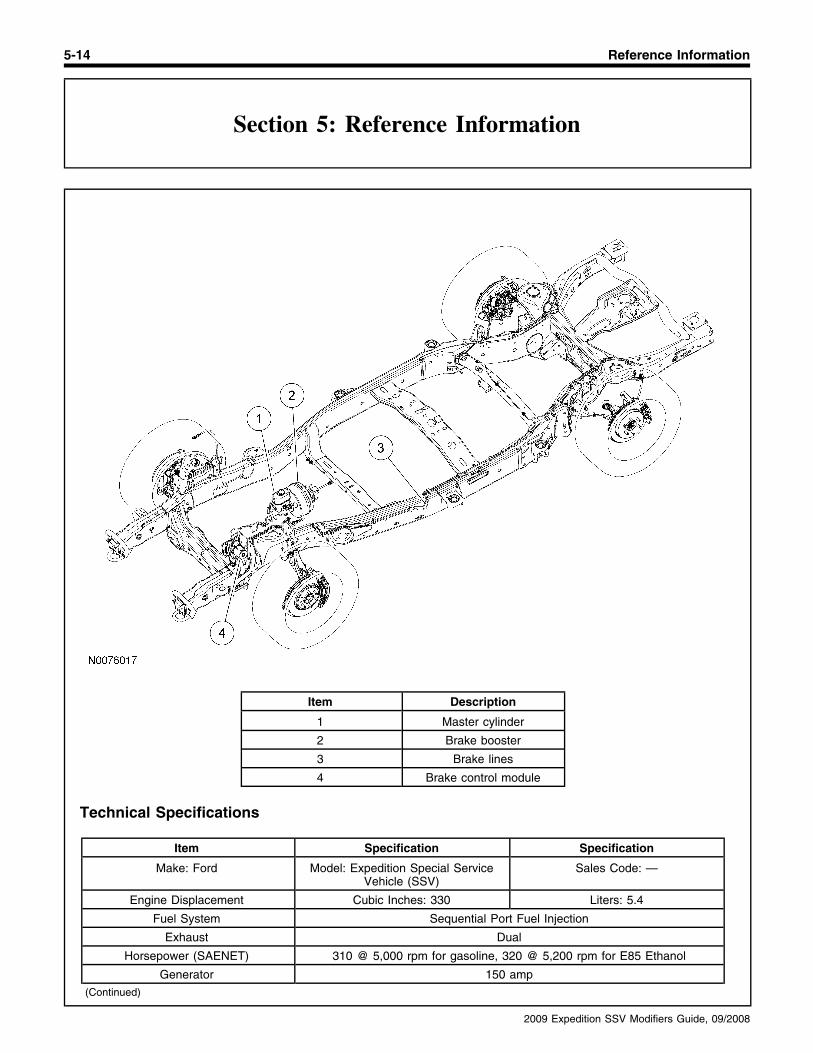
5-14 Reference Information
Section 5: Reference Information
Item Description
1 Master cylinder
2 Brake booster
3 Brake lines
4 Brake control module
Technical Specifications
Item Specification Specification
Make: Ford Model: Expedition Special Service Sales Code: —Vehicle (SSV)
Engine Displacement Cubic Inches: 330 Liters: 5.4
Fuel System Sequential Port Fuel Injection
Exhaust Dual
Horsepower (SAENET) 310 @ 5,000 rpm for gasoline, 320 @ 5,200 rpm for E85 Ethanol
Generator 150 amp(Continued)
2009 Expedition SSV Modifiers Guide, 09/2008

Reference Information 5-15
Section 5: Reference Information
Item Specification Specification
Torque 365 lb-ft @ 3,750 rpm
Battery 750 cca
Compression Ratio 9.8:1
Transmission Model: 6R80 Type: 6-speed electronic automaticwith lockup torque converter and
overdrive.
Axle Ratio 3.73:1
Gross vehicle weight rating (GVWR) 3,333 kg (7,350 lb) (Expedition) or 3,492 kg (7,700 lb) (Expedition EL)(4x2)
GVWR (4x4) 3,424 kg (7,550 lb) (Expedition) or 3,583 kg (7,900 lb) (Expedition EL)
Steering Power Rack and Pinion, variable ratio
Turning circle (curb to curb) 12.4 m (40.8 ft) (Expedition) or 15.0 m (43.9 ft) (Expedition EL)
Tire Size, Load and Speed Rating P265/70R17 A/S BSW (4x2) or P265/70/R17 A/T OWL (4x4)
Suspension Type (Front) Independent SLA with ball joint and coil spring
Suspension Type (Rear) 5-bar link with Watts Linkage
Fuel Capacity Liters: 105.9 (Expedition) or Gallons: 28.0 (Expedition) or 126.8 (Expedition EL) 33.5 (Expedition EL)
General Measurements Wheelbase: 3,022 mm (119.0 in) Length: 5,245 mm (206.5 in)(Expedition) or 3,327 mm (131.0 in) (Expedition) or 5,621 mm (221.3 in)
(Expedition EL) (Expedition EL)
General Measurements Width: 2,001 mm (78.8 in) —
General Measurements Track Width, Front: 1,701 mm Track Width, Rear: 1,706 mm(67.0 in) (67.2 in)
Head Room
First Row 1,005 mm (39.6 in) (Expedition) or 1,003 mm (39.5 in) (Expedition EL)
Second Row 1,010 mm (39.8 in) (Expedition) or 1,008 mm (39.7 in) (Expedition EL)
Third Row (optional) 972 mm (38.3 in) (Expedition) or 965 mm (38.0 in) (Expedition EL)
Leg Room
First Row 1,046 mm (41.2 in)
Second Row 993 mm (39.1 in)
Third Row (optional) 957 mm (37.7 in)
Shoulder Room
First Row 1,605 mm (63.2 in)
Second Row 1,617 mm (63.7 in)
Third Row (optional) 1,318 mm (51.9 in) (Expedition) or 1,704 mm (67.1 in) (Expedition EL)
Hip Room
First Row 1,529 mm (60.2 in)
Second Row 1,521 mm (59.9 in)
Third Row (optional) 1,275 mm (50.2 in) (Expedition) or 1,316 mm (51.8 in) (Expedition EL)
Cargo Volume
Behind First Row Seat 3.06 cu m (108 cu ft) (Expedition) or 3.70 cu m (130.8 cu ft) (Expedition EL)
Behind Second Row Seat 1.53 cu m (54 cu ft) (Expedition) or 2.42 cu m (85.5 cu ft) (Expedition EL)(Continued)
2009 Expedition SSV Modifiers Guide, 09/2008

5-16 Reference Information
Section 5: Reference Information
Item Specification Specification
Behind Third Row Seat (optional) 0.51 cu m (18 cu ft) (Expedition) or 1.21 cu m (42.6 cu ft) (Expedition EL)
EPA Mileage Est. (mpg) City: 16/Highway: 22 Combined: 18
Mileage Est. (km/L) City: 6.8/Highway: 9.3 Combined: 7.7
2009 Expedition SSV Modifiers Guide, 09/2008