
cata 09-10
43
-
Upload
khangminh22 -
Category
Documents
-
view
0 -
download
0
Transcript of cata 09-10

[email protected] PRODUCTS 2 YEARS GUARANTEE
www.langlois-france.com
Solar energy
ref. SOL-1 Electrical cabinet + 2 Photovoltaic panels + 1 link cable
ref. SOL-1-N Electrical cabinet only
Sold without panel. Use your own panels with characteristics comprise between 35 and 150VDC.
3. PHOTOVOLTAIC SOLAR PANEL 200WC ON TILTING FRAME (FOR EACH PANEL)• Open circuit voltage: 57V DC • Short-circuit current: 4.6A • Optimum operating voltage: 47V DC • Optimum operating current: 4.3A • Maximum power: 200Wc
(variation of ± 10% depending on the series) • Sealed connections IP65 – 1000V
on the rear of the panel. • Type of cells: Monocrystalline silicon • Robust aluminium frame. • Useful surface area of the cells 1.5m². • Output 47VDC – 4.2A – 200Wc per panel on 2
photovoltaic terminals. • Device for measuring the tilt angle • Tilt adjustable from 5° to 70° • Two ball joints with clamping levers for positioning
the panel to the required tilt angle. • Light and easy to move.
Folded position: 1620 x 1060 x 100mm Unfolded to 70° position: 2100 x 1060 x 700mm
1. ELECTRICAL CABINET Technical cabinet of standardized solar central unit on wheeled frame. Dimensions: 810 x 600 x 1890mm Comprises • 2 disconnectors • 1 500mA -30A differential • 1 30mA differential • 1 lightning arrester + fuses • 3 100 Wh resolution meters • 1 Mushroom head emergency stop • 1 source inverter • 1 charging controller 12/24VDC-20A • 2 batteries 12V-12Ah • 1 set of photovoltaic connectors • 1 500W inverter for network synchronisation • 1 Voltage converter 24VDC/230VAC-200W
2. LINK CABLE 30-m cable for connecting the solar panels to any type of solar system.
Technical characteristic for the inverter coupled to the electrical grid.
PARTIAL OR TOTAL RESALE OPERATION In the cabinet a DC/AC inverter converts the DC from the photovoltaic panels to AC 220VAC 50Hz, and in-jects its power in synchronism into the electrical grid. This inverter is protected against any polarity reversal and any overload on the DC or AC side. When the panels are not lit, the inverter consumes no current.
Technical characteristics of converter for isolated site
OPERATION IN ISOLATED SITE WITH NO RESALE The photovoltaic current charges two 12V sealed batteries cabled in series through a charge controller. This DC voltage is either available on safety terminals at the rear of the cabinet or converted to 250VAC 50Hz by a 300VA voltage converter.
SOLAR CENTRAL UNIT WITH NETWORK INJECTION AND ISOLATED SITE
Supplied with 1 pyranometer
• Understanding the different elements of a photovoltaic system. • Understanding the safety components involved in the system. • Electrical measurements of different parameters. • Analyzing and interpreting results. • Studying the efficiency and impacts related to the positioning of the
solar panels. • Studying of the chain of solar energy
(production, storage, consumption, resale, energetic behavior). • Wiring of a photovoltaic system.
EDUCATIONAL OBJECTIVES
TEACHING RESOURCES STUDENT & TEACHER
VOLTAGE CONVERTER Voltage Max Current PowerINPUT 20~32 VDC 11AOUTPUT 230VAC 50Hz 1,5A 300VA
INVERTER Voltage Max current Power
INPUT 65~125VDC 8A
OUTPUT 230VAC-50Hz 2,25A 500W

[email protected] PRODUCTS 2 YEARS GUARANTEE
www.langlois-france.com
Solar energy
D3500mA
D430mA
D5 D6 D7
2P+T500W
2P+T
D130mAF1
24V-DC 230V-AC 230V-AC
ETUDE VENTE PRODUCTION ENERGIE
230Vca
100Vccenv.
230Vca
I4 I5
Cde Eclairage
230Vca 230Vca
Eclairage Dressing
Eclairage Salon
I6
U - Secteur
Protections
Tableau Modulaire
Onduleur
130Vcc -Max
Panneaux Photovoltaiques
Armoire Technique
!
N
Ph
Chauffage
I7
W1
W2 W3
Compteur Habitation
Compteurs Production
RESEAU ERNERGIE ELECTRIQUE230Vca - Monophase
Liaison : Vente du SURPLUS de consommation
Liaison : Vente de TOUTE la production
230Vca
500W
Cde Eclairage
600W
ouVariante de Cablage
(cf Notice)
ETUDE SUR SITE ISOLE
+- +- +-
24Vccenv.
24Vccenv.
230Vca
24Vccenv.
230Vca
48Vccenv.
230Vca - MAX:250VA
U - LAMPES
I1 - Eclairage Cuisine I2 - Eclairage Chambre
Cde Eclairage Cuisine Cde Eclairage Chambre
24Vcc 24Vcc
Eclairage ChambreEclairage Cuisine
I3 - Prise 2P+T
U - Prise 2P+T
Protections
Tableau Modulaire
Régulateur de tension
Onduleur
250VA
24V-cc
230V-ca
Batterie 1 Batterie 2
+- +-
12Vccenv. 12Vccenv.
Armoire Technique
!
!IMPORTANT: Tension en Sortie
des Panneaux MAX: 48VRespecter le Cablage (cf notice)
+ +
+ +- + N
Ph
Panneaux Photovoltaiques
SYNOPTIC UNITS
NETWORK USINGZONE FOR
230V-AC
P F1C
ELECTRICAL NETWORK
DC / 24DC
DC230VAC
50Hz
BATT.
DC230VAC
INVERTER
Q
D2500mA
D130mA
Q
KWh
SOL1
230V-ACKWh KWh
50Hz
SOL200
HABITAT 1
NETW
ORK I
NJE
CTIO
N
SOL200
GARAGE ROOM
230V-50HZ
DC
DC AC
AC
AC
230V-AC
230V-AC
24V-DC
ISOLATED SITEZONE FOR
230V-AC
AC
DC
USING SOLAR ENERGY WITH PUBLIC NETWORK INJECTION AND ISOLATED SITE CHOOSE SOL-1 + HABITAT-1
Double function Network injection and isolated site
RECOMMENDED OPTION LOADING PANEL FOR ISOLATED SITE USE
SEE REF. HABITAT-1
RECOMMENDED OPTION FOR INDOOR OPERATION ARTIFICIAL SOLAR SOURCE QTE 2.
SEE REF. SOL-ARTI2
Requires download in Play Store or Apple Store the free application “Victron Energy”. Display on tablet or Smartphone: - Voltage – Current of the panel / Power (W) - Voltage – Current of the battery / Charge current - On-Off state charge
Smar
tpho
ne n
ot s
uppl
ied

[email protected] PRODUCTS 2 YEARS GUARANTEE
www.langlois-france.com
Solar energy
ref. SOL-2 Electrical cabinet + 2 Photovoltaic panels + 1 link cable
3. PHOTOVOLTAIC SOLAR PANEL 200WC ON TILTING FRAME (FOR EACH PANEL)
• Open circuit voltage: 57V DC • Short-circuit current: 4.6A • Optimum operating voltage: 47V DC • Optimum operating current: 4.3A • Maximum power: 200Wc
(variation of ± 10% depending on the series) • Sealed connections IP65 – 1000V
on the rear of the panel. • Type of cells: Monocrystalline silicon • Robust aluminium frame. • Useful surface area of the cells 1.5m². • Output 47VDC – 4.2A – 200Wc per panel
on 2 photovoltaic terminals. • Device for measuring the tilt angle • Tilt adjustable from 5° to 70° • Two ball joints with clamping levers for positioning
the panel to the required tilt angle. • Light and easy to move.
Folded position: 1620 x 1060 x 100mm Unfolded to 70° position: 2100 x 1060 x 700mm
1. ELECTRICAL CABINET Technical cabinet of standardized solar central unit on wheeled frame. Dimensions: 810 x 600 x 1890mm Comprises • 2 disconnectors • 1 500mA -30A differential • 1 30mA differential • 1 lightning arrester + fuses • 1 Mushroom head emergency stop • 3 100 Wh resolution meters • 1 set of photovoltaic connectors • 1 500W inverter for network synchronisation
2. LINK CABLE 30-m cable for connecting the solar panels to any type of solar system.
ref. SOL-2-N Electrical cabinet only
Sold without panel. Use your own panels with characteristics comprise between 35 and 150VDC.
SOLAR CENTRAL UNIT WITH NETWORK INJECTION
Supplied with 1 pyranometer
• Understanding the different elements of a photovoltaic system. • Understanding the safety components involved in the system. • Electrical measurements of different parameters. • Analyzing and interpreting results. • Studying the efficiency and impacts related to the positioning
of the solar panels. • Studying of the chain of solar energy
(production, storage, consumption, resale, energetic behavior). • Wiring of a photovoltaic system.
EDUCATIONAL OBJECTIVES
TEACHING RESOURCES STUDENT & TEACHER
MODULAR
SOLUTION
Technical characteristic for the inverter coupled to the electrical grid.
PARTIAL OR TOTAL RESALE OPERATION In the cabinet a DC/AC inverter converts the DC from the photovoltaic panels to AC 220VAC 50Hz, and injects its power in synchronism into the electrical grid. This inverter is protected against any polarity reversal and any overload on the DC or AC side. When the panels are not lit, the inverter consumes no current.
INVERTER Voltage Max current Power
INPUT 65~125VDC 8A
OUTPUT 230VAC-50Hz 2,25A 500W

[email protected] PRODUCTS 2 YEARS GUARANTEE
www.langlois-france.com
Solar energy
D3500mA
D430mA
D5 D6 D7
2P+T
500W230V-AC
ETUDE VENTE PRODUCTION ENERGIE
230Vca
100Vccenv.
230Vca
I4 I5
Cde Eclairage
230Vca 230Vca
Eclairage Dressing
Eclairage Salon
I6
U - Secteur
Protections
Tableau Modulaire
Onduleur
130Vcc -Max
Panneaux Photovoltaiques
Armoire Technique
!
N
Ph
Chauffage
I7
W1
W2 W3
Compteur Habitation
Compteurs Production
RESEAU ERNERGIE ELECTRIQUE230Vca - Monophase
Liaison : Vente du SURPLUS de consommation
Liaison : Vente de TOUTE la production
230Vca
500W
Cde Eclairage
600W
ouVariante de Cablage
(cf Notice)
SYNOPTIC UNIT
230V-AC
P F1I
ELECTRICAL NETWORK
DC230VAC
INVERTER
Q
D2500mA
D1
30mA
Q
KWh
230V-ACKWh KWh
50Hz
SOL200
HABITAT 2
SOL200
SOL2
GARAGE ROOM
230V-50HZ
DC
DCAC
AC
AC
USING
230V-AC
NETWORK INJECTION
USING SOLAR ENERGY WITH PUBLIC NETWORK INJECTION CHOOSE SOL-2 + HABITAT-2
Simple function Network injection
RECOMMENDED OPTION LOADING PANEL FOR USE ON SITE WITH ELECTRICITY NETWORK
SEE REF. HABITAT-2
RECOMMENDED OPTION FOR INDOOR OPERATION ARTIFICIAL SOLAR SOURCE QTE 2.
SEE REF. SOL-ARTI2

[email protected] PRODUCTS 2 YEARS GUARANTEE
www.langlois-france.com
Solar energy
ref. SOL-3 Electrical cabinet + 2 Photovoltaic panels + 1 link cable
ref. SOL-3-N Electrical cabinet only
Sold without panel. Use your own panels with characteristics comprise between 18 and 150VDC.
3. PHOTOVOLTAIC SOLAR PANEL 200WC ON TILTING FRAME (FOR EACH PANEL)
• Open circuit voltage: 57V DC • Short-circuit current: 4.6A • Optimum operating voltage: 47V DC • Optimum operating current: 4.3A • Maximum power: 200Wc
(variation of ± 10% depending on the series) • Sealed connections IP65 – 1000V
on the rear of the panel. • Type of cells: Monocrystalline silicon • Robust aluminium frame. • Useful surface area of the cells 1.5m². • Output 47VDC – 4.2A – 200Wc per panel
on 2 photovoltaic terminals. • Device for measuring the tilt angle • Tilt adjustable from 5° to 70° • Two ball joints with clamping levers for positioning
the panel to the required tilt angle. • Light and easy to move.
Folded position: 1620 x 1060 x 100mm Unfolded to 70° position: 2100 x 1060 x 700mm
1. ELECTRICAL CABINET Technical cabinet of standardized solar central unit on wheeled frame. Dimensions: 810 x 600 x 1890mm Comprises • 2 disconnectors • 1 lightning arrester + fuses • 1 Mushroom head emergency stop • 1 charging controller 12/24VDC-20A • 2 batteries 12V-12Ah • 1 set of photovoltaic connectors • 1 Voltage converter 24VDC/230VAC-200W
2. LINK CABLE 30-m cable for connecting the solar panels to any type of solar system.
• Understanding the different elements of a photovoltaic system. • Understanding the safety components involved in the system. • Electrical measurements of different parameters. • Analyzing and interpreting results. • Studying the efficiency and impacts related to the positioning of the solar panels. • Studying of the chain of solar energy (production, storage, resale, energetic behavior). • Wiring of a photovoltaic system.
EDUCATIONAL OBJECTIVES
TEACHING RESOURCES STUDENT & TEACHER
Supplied with 1 pyranometer
SOLAR CENTRAL UNIT FOR ISOLATED SITE
MODULAR
SOLUTION
Technical characteristics of converter for isolated site
OPERATION IN ISOLATED SITE WITH NO RESALE The photovoltaic current charges two 12V sealed batteries cabled in series through a charging controller. This DC voltage is used directly by low energy consumption lamps 24VDC, and/or converted to 250VAC 50Hz by a 300VA voltage converter.
VOLTAGE CONVERTER Voltage Max current Power
INPUT 20~32 VDC 11AOUTPUT 230VAC 50Hz 1,5A 300VA

[email protected] PRODUCTS 2 YEARS GUARANTEE
www.langlois-france.com
Solar energy
2P+T
D130mAF1
24V-DC 230V-AC
ETUDE SUR SITE ISOLE
+- +- +-
24Vccenv.
24Vccenv.
230Vca
24Vccenv.
230Vca
48Vccenv.
230Vca - MAX:250VA
U - LAMPES
I1 - Eclairage Cuisine I2 - Eclairage Chambre
Cde Eclairage Cuisine Cde Eclairage Chambre
24Vcc 24Vcc
Eclairage ChambreEclairage Cuisine
I3 - Prise 2P+T
U - Prise 2P+T
Protections
Tableau Modulaire
Régulateur de tension
Onduleur
250VA
24V-cc
230V-ca
Batterie 1 Batterie 2
+- +-
12Vccenv. 12Vccenv.
Armoire Technique
!
!IMPORTANT: Tension en Sortie
des Panneaux MAX: 48VRespecter le Cablage (cf notice)
+ +
+ +- + N
Ph
Panneaux Photovoltaiques
SYNOPTIC UNIT
230V-AC
P F1I
DC / 24DC
DC
230VAC50Hz
BATT.
SOL3
SOL200
HABITAT 3
SOL200
GARAGE ROOM
DC
DC
230V-AC
24V-DC
REGULATOR
VOLTAGECONVERTER
USING SOLAR ENERGY ON AN ISOLATED SITE WITHOUT PUBLIC NETWORK ACCESS - CHOOSE SOL-3 + HABITAT-3
Simple function Isolated site
RECOMMENDED OPTION LOADING PANEL FOR ISOLATED SITE USE
SEE REF. HABITAT-3
RECOMMENDED OPTION FOR INDOOR OPERATION ARTIFICIAL SOLAR SOURCE QTE 2.
SEE REF. SOL-ARTI2
Requires download in Play Store or Apple Store the free application “Victron Energy”. Display on tablet or Smartphone: - Voltage – Current of the panel / Power (W) - Voltage – Current of the battery / Charge current - On-Off state charge
Smar
tpho
ne n
ot s
uppl
ied
[email protected] PRODUCTS 2 YEARS GUARANTEE
www.langlois-france.com
Solar energy
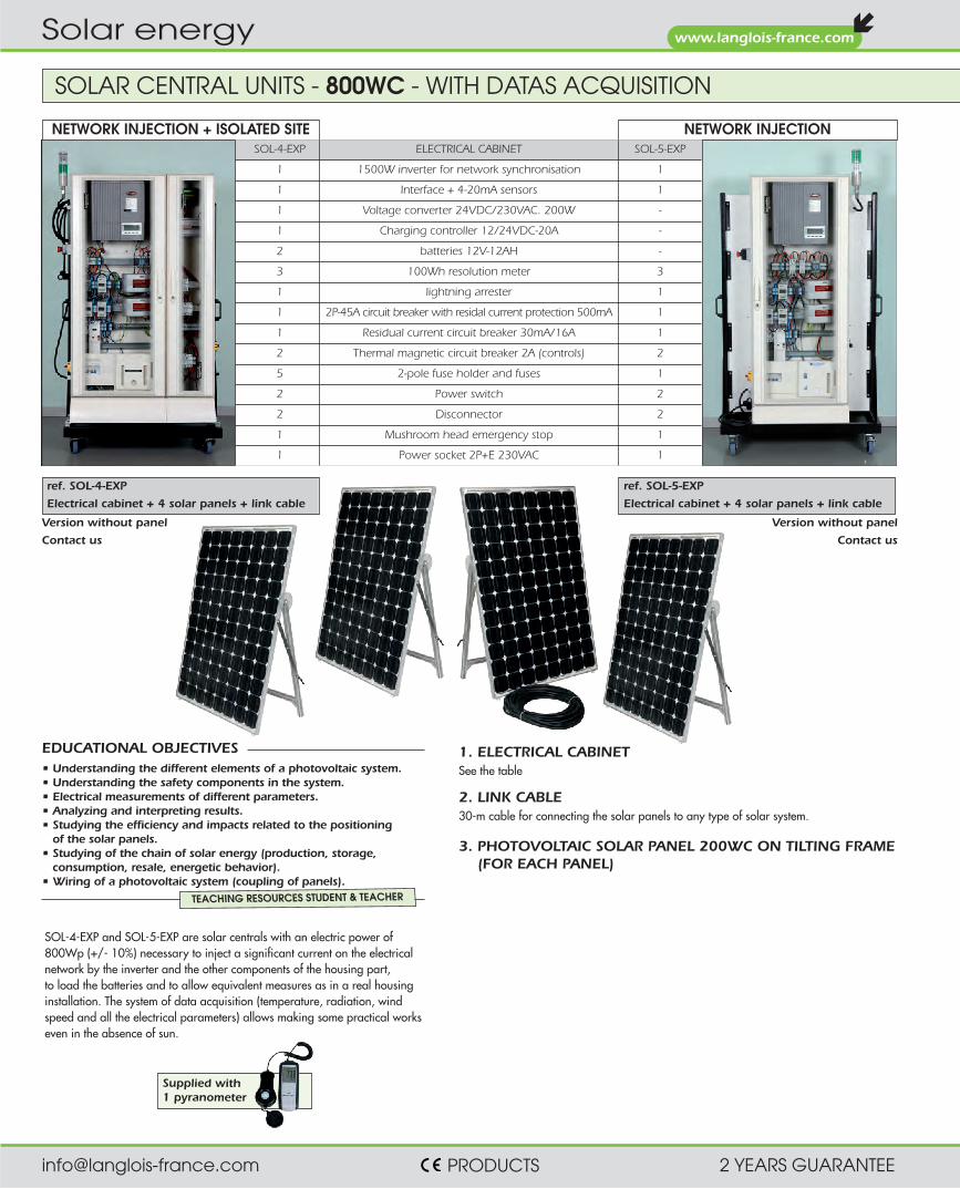
SOLAR CENTRAL UNITS - 800WC - WITH DATAS ACQUISITION
Supplied with 1 pyranometer
NETWORK INJECTION + ISOLATED SITE NETWORK INJECTIONSOL-4-EXP ELECTRICAL CABINET SOL-5-EXP
1 1500W inverter for network synchronisation 1
1 Interface + 4-20mA sensors 1
1 Voltage converter 24VDC/230VAC. 200W -
1 Charging controller 12/24VDC-20A -
2 batteries 12V-12AH -
3 100Wh resolution meter 3
1 lightning arrester 1
1 2P-45A circuit breaker with residal current protection 500mA 1
1 Residual current circuit breaker 30mA/16A 1
2 Thermal magnetic circuit breaker 2A (controls) 2
5 2-pole fuse holder and fuses 1
2 Power switch 2
2 Disconnector 2
1 Mushroom head emergency stop 1
1 Power socket 2P+E 230VAC 1
ref. SOL-4-EXP
Electrical cabinet + 4 solar panels + link cable
ref. SOL-5-EXP
Electrical cabinet + 4 solar panels + link cable
• Understanding the different elements of a photovoltaic system. • Understanding the safety components in the system. • Electrical measurements of different parameters. • Analyzing and interpreting results. • Studying the efficiency and impacts related to the positioning
of the solar panels. • Studying of the chain of solar energy (production, storage,
consumption, resale, energetic behavior). • Wiring of a photovoltaic system (coupling of panels).
EDUCATIONAL OBJECTIVES
TEACHING RESOURCES STUDENT & TEACHER
Version without panel
Contact us
Version without panel
Contact us
SOL-4-EXP and SOL-5-EXP are solar centrals with an electric power of 800Wp (+/- 10%) necessary to inject a significant current on the electrical network by the inverter and the other components of the housing part, to load the batteries and to allow equivalent measures as in a real housing installation. The system of data acquisition (temperature, radiation, wind speed and all the electrical parameters) allows making some practical works even in the absence of sun.
3. PHOTOVOLTAIC SOLAR PANEL 200WC ON TILTING FRAME (FOR EACH PANEL)
2. LINK CABLE 30-m cable for connecting the solar panels to any type of solar system.
1. ELECTRICAL CABINET See the table

ref. HABITAT-1 PAGE 133
ref. HABITAT-2 PAGE 133
[email protected] PRODUCTS 2 YEARS GUARANTEE
www.langlois-france.com
Solar energy
FUNCTIONING DIAGRAM OF SOL-4-EXP + HABITAT-1
FUNCTIONING DIAGRAM OF SOL-5-EXP + HABITAT-2
INTERFACE AND SENSORS DELIVERED WITH SOL-4-EXP AND SOL-5-EXP Measure of the solar radiation Temperature of the solar panels Wind speed These physical parameters and also the electri-cal parameters (voltage and current AC/DC), the power and the energy are recorded (1 year of data maximum) by an interface placed in the electrical cabinet and monitored by a PC. The software provided with SOL-5 and SOL-4 allows to display one or several curves on the screen, diagrams, … All data can be exported to Excel®.
Screenshoot of 3 recordings made during the day : Instant alternative power, temperature of panels, intensity of solar radiation.
Screenshoot showing the voltage and the power at the output of the inverter, the temperature of panels. Scales are specified with units.
WARRANTY Factory guarantee of the inverter: 5 years The website of Fronius offers the free update of the software, and answers the Frequently Asked Questions.
SUPPLIED ACCESSORIES • A connection cable of 30 meters – 3x 6mm²
panels/electrical cabinet • A connection cable of 30 meter for the link
sensors/interface for signal 4-20mA • A CD-rom with all the pratical works • A software for the exploitation of data • A pyranometer for measuring the solar
radiation (200 and 2000 W/m² range)
TECHNICAL CHARACTERISTIC FOR THE INVERTER COUPLED TO THE PUBLIC NETWORK.
PARTIAL OR TOTAL RESALE OPERATION (SOL-4-EXP AND SOL-5-EXP)In the cabinet a DC/AC inverter converts the DC from the photovoltaic panels to AC 220VAC 50Hz, and injects its power in synchronism into the network through an isolation transformer. This inverter is protected against any polarity reversal and any overload on the DC or AC side. When the panels are not lit, the inverter consumes no current.
TECHNICAL CHARACTERISTICS FOR THE ISOLATED SITE CONVERTER
OPERATION IN ISOLATED SITE WITH NO RESALE (SOL-4-EXP ONLY)The photovoltaic current charges two 12V sealed batteries cabled in series through a charging controller. This DC voltage is used directly by low energy consumption lamps 24VDC, and/or converted to 250VAC 50Hz by a 200W voltage converter.
VOLTAGE CONVERTER Voltage Max current Power
INPUT 20~32 VDC 11A 210W
OUTPUT 230VAC 50Hz 1A 200VA
INVERTER Voltage Max current Power Cos Distorsion Rendement
INPUT 150~450VDC 10,8A
OUTPUT 230VAC-50Hz 6,5A 1,5kW 1 ≤3,5% 91%
[email protected] PRODUCTS 2 YEARS GUARANTEE
www.langlois-france.com
Solar energy
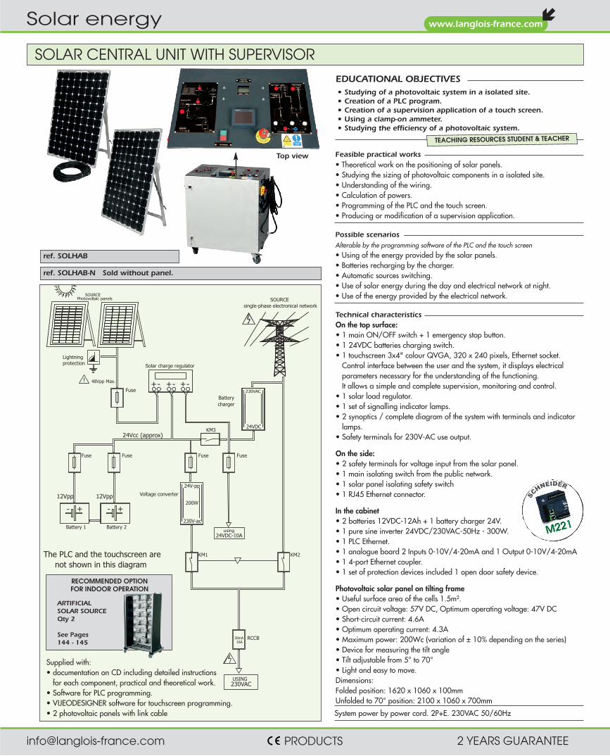
Technical characteristics On the top surface: • 1 main ON/OFF switch + 1 emergency stop button. • 1 24VDC batteries charging switch. • 1 touchscreen 3x4" colour QVGA, 320 x 240 pixels, Ethernet socket.
Control interface between the user and the system, it displays electrical parameters necessary for the understanding of the functioning. It allows a simple and complete supervision, monitoring and control.
• 1 solar load regulator. • 1 set of signalling indicator lamps. • 2 synoptics / complete diagram of the system with terminals and indicator
lamps. • Safety terminals for 230V-AC use output. On the side: • 2 safety terminals for voltage input from the solar panel. • 1 main isolating switch from the public network. • 1 solar panel isolating safety switch • 1 RJ45 Ethernet connector. In the cabinet • 2 batteries 12VDC-12Ah + 1 battery charger 24V. • 1 pure sine inverter 24VDC/230VAC-50Hz - 300W. • 1 PLC Ethernet. • 1 analogue board 2 Inputs 0-10V/4-20mA and 1 Output 0-10V/4-20mA • 1 4-port Ethernet coupler. • 1 set of protection devices included 1 open door safety device. Photovoltaic solar panel on tilting frame • Useful surface area of the cells 1.5m². • Open circuit voltage: 57V DC, Optimum operating voltage: 47V DC • Short-circuit current: 4.6A • Optimum operating current: 4.3A • Maximum power: 200Wc (variation of ± 10% depending on the series) • Device for measuring the tilt angle • Tilt adjustable from 5° to 70° • Light and easy to move. Dimensions: Folded position: 1620 x 1060 x 100mm Unfolded to 70° position: 2100 x 1060 x 700mm
Photovoltaic panels
24VDC-10Ausing
USING230VAC
Fuse
48Vpp Max.
Battery 1
12Vpp
- +
Lightningprotection
!
Battery 2
- +
12Vpp
16A30mA RCCB
230V-ac
200W
Voltage converter
Fuse
24Vcc (approx)
24V-pp
Fuse Fuse
Solar charge regulator
Fuse
-+ -+ -+
single-phase electronical network
24VDC
230VAC
Batterycharger
KM1 KM2
KM3
SOURCESOURCE
The PLC and the touchscreen arenot shown in this diagram
Supplied with: • documentation on CD including detailed instructions
for each component, practical and theoretical work. • Software for PLC programming. • VIJEODESIGNER software for touchscreen programming. • 2 photovoltaic panels with link cable
ref. SOLHAB-N Sold without panel.
ref. SOLHAB
Top view
SOLAR CENTRAL UNIT WITH SUPERVISOR
• Studying of a photovoltaic system in a isolated site. • Creation of a PLC program. • Creation of a supervision application of a touch screen. • Using a clamp-on ammeter. • Studying the efficiency of a photovoltaic system.
EDUCATIONAL OBJECTIVES
TEACHING RESOURCES STUDENT & TEACHER
Feasible practical works • Theoretical work on the positioning of solar panels. • Studying the sizing of photovoltaic components in a isolated site. • Understanding of the wiring. • Calculation of powers. • Programming of the PLC and the touch screen. • Producing or modification of a supervision application.
Possible scenarios Alterable by the programming software of the PLC and the touch screen • Using of the energy provided by the solar panels. • Batteries recharging by the charger. • Automatic sources switching. • Use of solar energy during the day and electrical network at night. • Use of the energy provided by the electrical network.
System power by power cord. 2P+E. 230VAC 50/60Hz
RECOMMENDED OPTION FOR INDOOR OPERATION
ARTIFICIAL SOLAR SOURCE Qty 2 See Pages 144 - 145

[email protected] PRODUCTS 2 YEARS GUARANTEE
www.langlois-france.com
Solar energy
Set of sensors, interfaces and software for the real time data monitoring of a photovoltaic installation. COMPRISES • Three 4-20mA sensors for reading wind speed (m/s), solar irradiation (W/m2) and the temperature of the solar panel (°C). • 1 sealed "solar panel power interface" box for reading the voltage and current supplied by the photovoltaic panels.
This interface transmits information (U / I / Wind speed /temperature / irradiance) to the data interface as 4-20mA signals. Voltage 250VDC Max./Current 25A Max. • 1 "inverter power interface" box to be installed near the inverter reads the voltage and current supplied to the installation. U/I information is transmitted to the data interface
as 4-20mA signals. Voltage 250VDC Max./Current 20A Max • 1 "battery power interface" box to be installed near the batteries reads the voltage supplied to the installation. U information is transmitted
to the data interface as 4-20mA signals. Voltage 250VDC. • 1 "data interface" box collects the 4-20mA signals from the different power interfaces to transmit them to your PC. Mains power supply 230VAC - PC link by USB lead sup-
plied. • 1 Software for monitoring photovoltaic settings and data
Allows: - you to create your photovoltaic installation. - real time display as curves and numeric blocks of the different data of: wind speed, solar irradiation, panel temperature; U / I supplied by the solar panel; U / I supplied by the inverter; U supplied by the battery - the display, after acquisition, of the curves of electrical power supplied by the solar panels, electrical power supplied by the inverter, installation efficiency - selection of the sampling frequency for data acquisition (1 to 60 minutes), the acquisition period (1 minute to 24H), the display scales of the curves and their colours, data export to a spreadsheet like Excel®.
The Software is compatible with Windows XP, W7. Supplied on CD. All the connection cables and mounting accessories are supplied.
ref. ACQUI-SOL
ACQUISITION FOR CENTRAL UNIT

[email protected] PRODUCTS 2 YEARS GUARANTEE
www.langlois-france.com
Solar energy
NETWORK INJECTION AND ISOLATED SITE NETWORK INJECTION ISOLATED SITE
Synoptic for isolated site useSynoptic sale of energy production
Wheeled frame which reproduces domestic electrical installations on a vertical panel and enables the use of the voltage sources (AC + DC) produced by our solar central units SOL-1 to SOL-5. At the back another blank panel protects the electrical cables. Dimensions: 1000 x 500 x h 1600mm The frame is supplied assembled, fully cabled, ready to operate, with safety leads for the measuring units, and a CD including the technical data and cabling diagram.
Measurement with a clamp
LOADING ZONE FOR ISOLATED SITE USE This part includes a standard unit with standardized protection described below, and the different loads. • 1 differential circuit-breaker 16A/30mA • 1 two-pole fuse holder with fuse cartridges gPV
10x38 1000V • 2 24V DC low energy consumption light fittings
with switches • 2 light fittings 230VAC with switches • 1 230VAC 50Hz 2P+E socket • 1 mimic unit with safety terminals for I and U
measurements in different circuits. LOADING ZONE FOR USE ON SITE WITH ELECTRICITY NETWORK This part includes a standard unit with standardized protection described below, and the different loads. • 1 connection circuit-breaker 500mA • 1 differential circuit-breaker 16A/30mA • 3 thermal-magnetic circuit breakers • 2 light fittings 100W-230VAC with switches • 1 500W convector • 1 230VAC 50Hz 2P+E socket • 1 mimic unit with safety terminals for I and U
measurements in different circuits.
ref. HABITAT-1
LOADING ZONE FOR USE ON SITE WITH ELECTRICITY NETWORK This part includes a standard unit with standardized protection described below, and the different loads. • 1 connection circuit-breaker 500mA • 1 differential circuit-breaker 16A/30mA • 3 thermal-magnetic circuit breakers • 2 light fittings 100W-230VAC with switches • 1 500W convector • 1 230VAC 50Hz 2P+E socket • 1 mimic unit with safety terminals for I and U
measurements in different circuits.
ref. HABITAT-2
LOADING ZONE FOR ISOLATED SITE USE This part includes a standard unit with standardized protection described below, and the different loads. • 1 differential circuit-breaker 16A/30mA • 1 two-pole fuse holder with fuse cartridges gPV
10x38 1000V • 2 24V DC low energy consumption light fittings
with switches • 2 light fittings 230VAC with switches • 1 230VAC 50Hz 2P+E socket • 1 mimic unit with safety terminals for I and U
measurements in different circuits.
ref. HABITAT-3
LOADING PANELS FOR SOLAR CENTRAL UNITS
[email protected] PRODUCTS 2 YEARS GUARANTEE
www.langlois-france.com
Solar energy
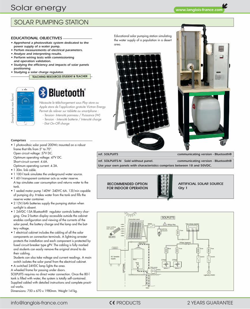
Nécessite le téléchargement sous Play store ou Apple store de l’application gratuite Victron Energy. Permet de relever sur tablette ou smartphone : - Tension- Intensité panneau / Puissance (W) - Tension - Intensité batterie / Intensité charge - Etat On-Off chargeSm
artp
hone
non
four
ni
SOLAR PUMPING STATION
Educational solar pumping station simulating the water supply of a population in a desert area.
ref. SOLPUITS communicating version - Bluetooth®
ref. SOLPUITS-N Sold without panel. communicating version - Bluetooth®
Use your own panels with characteristics comprises between 18 and 50VDC.
Comprises • 1 photovoltaic solar panel 200Wc mounted on a robust
frame that tilts from 5° to 70°. Open circuit voltage: 57V DC. Optimum operating voltage: 47V DC. Short-circuit current: 4.6A. Optimum operating current: 4.3A.
• 1 30m. link cable. • 1 100-l tank simulates the underground water source. • 1 60-l transparent container acts as water reserve.
A tap simulates user consumption and returns water to the tank.
• 1 sealed motor pump 140W- 24DVC-6A. 13l/min capable of pumping dry. It takes water from the tank and fills the reserve water container.
• 2 12V/6Ah batteries supply the pumping station when sunlight is absent.
• 1 24VDC-15A Bluetooth® regulator controls battery char-ging. One 2-button display accessible outside the cabinet enables configuration and viewing of the currents of the solar panel, the battery charge and the lamp and the bat-tery voltage.
• 1 electrical cabinet includes the cabling of all the solar components on connection terminals. A lightning arrester protects the installation and each component is protected by fused circuit-breaker type gPV. The cabling is fully marked and students can easily remove the original strand to do their cabling. Students can also take voltage and current readings. A main switch isolates the solar panel from the electrical cabinet.
• A switched 24VDC lamp lights the area. A wheeled frame for passing under doors. SOLPUITS requires no direct water connection. Once the 80-l tank is filled with water, the system is totally self-contained. Supplied cabled with detailed instructions and complete practi-cal works. Dimensions: 750 x 670 x 1980mm. Weight 141kg.
RECOMMENDED OPTION FOR INDOOR OPERATION
ARTIFICIAL SOLAR SOURCE Qty 1
SOLPUITS
+- +- +-
24Vpp (approx)
Lighting 24VDC
48Vpp Max. Solar charge regulator
Photovoltaic panel
Battery 1
Switch
+- +-
12Vpp 12Vpp
DC Variablesupply
Indoor artificialsolar source
SOL-ARTI
DC10
Lightningprotection Fuse
Fuse Fuse Fuse Fuse
Battery 2
WELL
Moto-pump
24VDC
Water
Valve
Water flow
MP-DC
Switch Switch
OPT
ION
S
!
• Apprehend a photovoltaic system dedicated to the power supply of a water pump.
• Perfom measurements of electrical parameters. • Analyze and interpreting results. • Perform wiring tests with commissioning
and operation validation. • Studying the efficiency and impacts of solar panels
positioning • Studying a solar charge regulator.
EDUCATIONAL OBJECTIVES
TEACHING RESOURCES STUDENT & TEACHER

[email protected] PRODUCTS 2 YEARS GUARANTEE
www.langlois-france.com
Solar energy
ref. SOL-PRO ref. SOL-PRO-N briefcase only
A synoptic shows the different components and the interconnections. Connection in jump wires by safety leads 4mm. Connection of the panels to the technical case by 2 photovoltaic leads (delivered). Measures are possible indoor by using the artificial solar source.
The SOL-PRO solar unit includes: 1 technical briefcase. 2 portable and folding photovoltaic panels. 1 artificial light source (3 spotlights). 2 cables to connect the panels to the case. 1 set of safety leads 4mm.
Electrical characteristics of the solar unit • photovoltaic panel (panel features):
- nominal power Pmpp: 30 Wc - max power voltage Vmpp: 18V DC - max power current Impp: 1.67 A - open circuit voltage Voc: 22.5V DC - short-circuit current Isc: 2A
• Power injected, with artificial source: 17 Wc (24V/0.7A)
• Output voltage 230 V - 50 Hz pure sinusoidal. 120 VA max.
• Output voltage 24V DC. 180W max
• Understand a photovoltaic installation of isolated site type. • Understand the security features of the system. • Perform wiring of a photovoltaic system. • Perform electrical measurements of different quantities. • Analyze & interpret the results. • Study the performance and impact of solar panels positioning • Study the energy chain (production, storage, use of a solar charge
controller for battery).
EDUCATIONAL OBJECTIVES
TEACHING RESOURCES STUDENT & TEACHER
Requires download in Play Store or Apple Store the free application “Victron Energy”. Display on tablet or Smartphone: - Voltage – Current of the panel / Power (W) - Voltage – Current of the battery / Charge current - On-Off state chargeSm
artp
hone
not
sup
plie
d
PORTABLE SOLAR CENTRAL UNIT FOR ISOLATED SITE WITH ARTIFICIAL LIGHT SOURCE
Composition of the technical case • Case made of impact-resistant polypropylene. It can be closed without disconnec-
ting the safety cords from the front. Light and easy to carry by its handle. • 2 photovoltaic sockets for connecting solar panels. • 1 surge arrester. • 1 Start/Stop switch to isolate the solar panel circuit from the technical case. • 4 two-pole fuse holders with gPV cartridge protecting the solar panel circuit,
batteries and use. • 1 24V/20A solar charge controller with display showing:
- battery charge - current supplied by the solar panels - battery charge current - current consumed by the use circuit - battery voltage.
• 1 voltage converter pure sinusoidal 50 Hz - 24/230V AC, 120 VA. Auto-protection by resettable thermal fuse.
• 1 set of 4 mm safety cords. • 1 output 230V AC - 120 VA on 4 mm safety terminals • 1 use output 24V DC - 180 VA on 4 mm safety terminals • Dimensions: 540 x 430 x 215mm Composition of the photovoltaic panels frame • Aluminium frame • 2 mono-crystalline photovoltaic panels, each 30 Wc. • 2 hinges for folding them together. • Separate cabling for series or parallel connection. • Useful surface area of the cells on each panel 0.2 m² • 2 ball joints for putting the panels at the tilt angle required. • 1 device for measuring the tilt angle. • 2 3-metre photovoltaic cords. • Light and easy to move (Carrying handle). • Dimensions in unfolded position: 1140 x 470 x 200 mm • Dimensions in folded position: 570 x 470 x 100 mm Composition of the artificial light source • 3 400W spotlights with variable tilt. • Power supply 230V AC 50/60 Hz by 2-metre mains cord. • Spotlight dimensions: 300 x 220 x h 360 mm Supplied with CD containing • Theoretical summary of the different types of photovoltaic cells and energy. • The detailed wiring diagram of the solar unit • 5 theoretical assignments and 3 complete practical assignments
as student/instructor book. • Full instructions for each component

[email protected] PRODUCTS 2 YEARS GUARANTEE
www.langlois-france.com
Solar energy
ref. VALSOL
SOLAR KIT
When closed, the panels are protected against impact and scratches. The following can be found underneath the solar panel: • a standard 15V DC 15 Ah Li-ion battery • a 12V DC/220V AC, 50Hz, 150W converter • a safety and monitoring electronics device Control panel • On/Off button • a circuit breaker to protect against over-currents • 4mm safety terminals for voltage and electric current inputs, with jumpers • the converter’s On/Off button • a 230V AC 50Hz socket with on and defect lamps
• a two-line LCD display delivering messages about the battery: temperature, % charge, charging current and voltage, usage current and voltage, undercharged battery, overcharged battery and overheating, etc., as well as the power output. NB: these are indications, rather than highly accurate measurements.
PROTECTION OF COMPONENT IN THE CASE OF
• battery overcharge: when its voltage reaches 16.5V the charging current is auto-matically cut, in order to preserve the battery’s service life.
• excessive battery discharge: When its voltage reaches 11.5V, an audible alarm will be triggered. When it falls below 10.5 V the output will be disconnected automatically.
• overload or short-circuit on the converter’s output SPECIFICATIONS OF THE SOLAR PANEL • Total surface area: 420 x 680mm • Total power: 30W • Typical voltage: 17.5V • Typical current: 1.7A • Short-circuit current: 1.9A • No-load circuit: 21.5V OTHER CHARACTERISTICS • Fitted side compartment for the storage of leads, jumpers, the targeting
system and the inclination stand . Dims: 570 x 380 x 160mm. Weight 17kg.
• Studying the principles of solar energy, storage and conversion. • Electrical measurements of different parameters. • Analyzing and interpreting results. • Studying the efficiency and impacts related to the positioning.
EDUCATIONAL OBJECTIVES
Suggested tutorials One of the jumpers isolates the photo-voltaic panels from the rest of the electronics. In this way, students can measure • The voltage in the no-load circuit (approximately 21V) • The short-circuit current (approximately 1.9A)
• The current and the voltage according to the lighting, by covering one of the two panels or by varying the tilt of the kit's lid in relation to the sun by an angle α; and check that the power output is a function of the power factor
• Using a rheostat (e.g. ECO1/2-330), students can look for the charge which corresponds to a maximum power supplied by the panel
The second jumper measures the DC level delivered by the battery. The third jum-per allows the current measuring at the converter’s input. Students can: • Measure the no-load voltage and current at the converter’s input, and calculate the
no-load power input
• Measure currents and voltages upstream and downstream of the converter and calculate the converter’s efficiency and losses by loading the 220V AC output.
• Check that the converter can supply up to 150W. Compare this power with the power supplied instantly by the panels. Draw conclusions about the role of the bat-tery.
Angle of incidence of sun rays measurement The solar kit VALSOL is supplied with a protractor and a simplified targeting system allowing the measuring (within a few degrees of precision) the angle of incidence of sun rays on the solar panels. This targeting system which is placed on side can be removed and stored in the side compartment dedicated to accessories storage. A stand
TEACHING RESOURCES STUDENT & TEACHER

[email protected] PRODUCTS 2 YEARS GUARANTEE
www.langlois-france.com
Solar energy
SOLAR LED STREET LAMP
COMPRISES • Wheeled aluminum frame, very stable, passes easily between doorways. • A monocrystalline photovoltaic panel of 80Wc fixed on an aluminum mat. The panel is adjustable. Allows
outdoor use in good weather. • A MPPT (Maximum Power Point Tracking) load control system and electronic device control with twilight
detection and voltage level programming directly modifiable from a smartphone or tablet. A recording of the voltages, currents and powers of the solar panel, battery and LEDs in the form of data can be retrieved by an application, in multi-languages, via a Bluetooth link (visualization in the form of a bargraph).
• A solar battery 12V / 60Ah. • A 40W lantern equipped with ultra-powerful latest generation LEDs with high light output with a color
temperature of 4500K and an IRC of 70. • An electronic LED power management device integrating a management system for reducing the luminous
flux and a detection of people. • A set of photovoltaic fuse holders. • A surge arrester. • A tutorial case containing all the components: inside the case, a silkscreen (insensitive to scratches) allows
to visualize through a synoptic the production chain of photovoltaic energy. The connection of the components is ensured by safety terminals 4mm allowing the student to carry out the cabling as well as electrical measurement points in complete safety.
PRACTICAL WORKS • Lessons on different solar panel technologies (Monocrystalline, Polycrystalline, Amorphous) • Study on the positioning of solar panels for maximum efficiency. • Mechanical attachment of the mat, the panel and the street lamp to the aluminum frame. • Study of solar irradiation. • Reminder on Direct, Diffused and Reflected Solar Radiation. • Study and execution of the wiring of the solar energy chain in isolated site. • Record currents and voltages at different points in the wiring. • Perform measures and then calculate efficiency. • Calculation of the discharge time of the battery according to the load. • Configuring the application from a touch pad. • Mechanical and electrical maintenance.
• Study street lighting with LED street lamp and solar energy. • Commission a solar system. • Demonstrate the ecological functioning of LED technology. • Discover the different technologies of solar panels. • Wire photovoltaic components, mechanically install a public lighting. • Perform electrical and mechanical maintenance on the street lamp. • Use hand tools. • Identify the different electrical quantities of a solar energy production line. • Calculate the performance of the installation. • Set up a Bluetooth network communication. • Set up a photovoltaic system from a tablet or a smartphone.
EDUCATIONAL OBJECTIVES
EDUCATIONAL SUPPORT • Technical leaflet in English • All technical “manufacturers” resources of components implemented on the system • 12 learning scenarios in the form of Practical Works (on cd-rom) of TEACHER / STUDENT type. • All the elements necessary for the planned practical work. • Answer sheets for student assessment.
TEACHING RESOURCES STUDENT & TEACHER
MAQ-DEL allows discovering and studying the operation of a Led solar lamp for communities or individuals for street lighting, a terrace, or any other type of application. Totally autonomous, the whole works with solar energy thanks to a set of photovoltaic components. Totally waterproof, the set can be used outdoors, thanks to large diameter wheels (200mm), to put it in a real context of use day and night.
ref. MAQ-DEL
Dimensions : 600 x 800 x 1700mm. Net Weight : 72kg.
Battery case + charge controller. Bluetooth
Monocrystalline panel of 80Wc
Ultra-powerful LEDs with high light output
[email protected] PRODUCTS 2 YEARS GUARANTEE
www.langlois-france.com
Solar energy
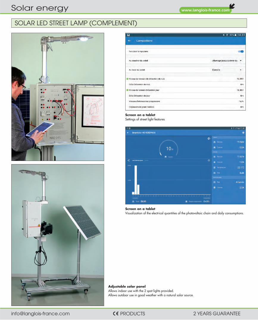
SOLAR LED STREET LAMP (COMPLEMENT)
Screen on a tablet Settings of street light features
Adjustable solar panel Allows indoor use with the 2 spot lights provided. Allows outdoor use in good weather with a natural solar source.
Screen on a tablet Visualization of the electrical quantities of the photovoltaic chain and daily consumptions.

[email protected] PRODUCTS 2 YEARS GUARANTEE
www.langlois-france.com
Solar energy
Features • 3-metre mains lead included, for the charger and artificial source. • Dimensions: 1100 x 600 x (H) 1600mm. Weight: 68kg. • The pole and the panels are easy to remove for going through doorways.
Practical works • Lessons on the different technologies of solar panels
(Monocristalline, Polycristalline, Amorphous) • Study on the positioning of solar panels for maximum output. • Study of solar radiation. • Reminder on Direct, Diffused and Reflected solar radiation. • Interpretations of the theoretical curves produced from the 3 solar sensors. • Study and creation of the wiring of a solar energy system at an isolated site. • Reading the currents and voltages at different points of the wiring. • Interpreting the measurements then calculation of the efficiency. • Calculation of the discharge time of the battery according to the load. • Creation of a controller program in contact language. • Downloading and setting up the Bluetooth® application
WORKSITE TRAFFIC LIGHTS - LED TECHNOLOGY – SELF-CONTAINED
• Study and putting into service of solar energy worksite traffic lights. • Reminder on the different solar panel technologies. • Wiring of the components of a photovoltaic installation at an isolated site. • Reading the different electrical values of the production system of solar energy. • Calculation of the efficiency of the installation. • Programming a controller (PLC). • Setting up a Bluetooth® connection
OBJECTIFS PÉDAGOGIQUES
Comprises • 2 traffic lights with Red / Orange / Green LEDS. • 2 photovoltaic panels 30W/12V Monocristalline. • 2 artificial sources. with light controller. • 1 electrical cabinet with :
- 1 Voltmeter measures the voltage of the photovoltaic panels. - 1 Voltmeter measures the voltage of the 2 batteries. - 1 Set of pushbuttons, switches and indicator lights. - 1 front synoptic gives the overall diagram of the system. 4mm connection terminals enable reading of U/I panels, U/I batteries, U/I charge and I charger. - 1 SCHNEIDER® programmable logic controller (PLC). - 1 solar load regulator 24VDC/15A Bluetooth®. - 1 battery charger 12V. - 2 batteries 12V-8Ah. - 1 set of electrical protection with gPV cartridge fuses.
Simulator of worksite traffic lights powered with solar energy. Two artificial and variable light sources simulate sunlight and enable the batteries to be recharged. Fully self-contained, operation of the FEU-LED is managed with a Schneider® PLC. One solution for manually recharging the batteries is included in the electrical unit for better organization of the explanations and practical work.
ref. FEU-LED communicating version - Bluetooth®
Requires download in Play Store or Apple Store the free application “Victron Energy”. Display on tablet or Smartphone: - Voltage – Current of the panel / Power (W) - Voltage – Current of the battery / Charge current - On-Off state charge Sm
artp
hone
not
sup
plie
d

[email protected] PRODUCTS 2 YEARS GUARANTEE
www.langlois-france.com
Solar energy
DUAL ENERGY ELECTRIC GATES, SOLAR OR MAINS 230VAC
• To observe and understand the operation of electric gate automation. • Reminder about the different solar panel technologies. • To study the operation of an assembly of solar panel, battery, charge regulator. • To take measurements of electrical values. • To study the operation of photo-electric cells. • To learn how to program gate automation according to several operating criteria. • To perform industrial maintenance operations.
EDUCATIONAL OBJECTIVES
TEACHING RESSOURCES STUDENT & TEACHER
Practical works • Study and identification of the different components of the gate. • Measurement of the current, voltage and power absorbed by the motors. • Measurement of the current, voltage, and solar power. • Study of the operating principle of photo-electric cells. • Configuring the different gate operations.
Composition of the gates • One electronic unit with control board equipped with digital display and three pushbuttons
for configuring the assembly. • One console with printed diagram of the different components including all the gate's
connectors. Interconnection with safety leads supplied. • Two gear motors 24VDC with hinged arm (version POA-1)
and one motor 24VDC (version POA-2). • One signalling light. • One pair of photocells. • One face equipped with 2 indicator lights to simulate lighting in the gate opening area
and garden lighting. • One two position switch for opening/closing of the gate, or a single leaf (for version POA-1). • One unit with battery 24V-12Ah and charge regulator 24VDC
Automated solar swing gates (POA-1). Automated solar sliding gate (POA-2). All the electrical connectors of the components (motors, cells, light, control board) are brought to one front using 4mm safety terminals. Thus the student can wire, using the safety leads, all the operations of the gate with no risk of deterioration of the screws or connectors of the components. They can also quite safely read the different vol-tages and currents of the system. The many operating parameters can be modified in the electrical cabinet using the programming console with digital display. There are two types of power supply wi-ring for the gates: • Wiring by solar energy power supply.
The solar panel is linked to the gate's electrical cabinet. Operation is autonomous thanks to the 24VDC batteries.
• Wiring directly to the electricity mains 230VAC using its mains lead with plug 2P+E.
ref. POA-1 swing gates
ref. POA-2 sliding gate
The assembly is supplied fully functional with examples of opera-tion. A CD contains the user instructions and tutorials. Dimensions: Overall: H 1700 x W 1400 x 630mm (POA-1) Overall: H 1700 x W 1800 x 630mm (POA-2)
The gates POA-1 and POA-2 are supplied with an autonomous wheeled frame comprising a solar panel 25W-24VDC and two spotlights simulating the sun. Non-solar versions Ref. POA-11 and POA-22
POA-1 - House side viewPOA-1 - Street side view
[email protected] PRODUCTS 2 YEARS GUARANTEE
www.langlois-france.com
Solar energy
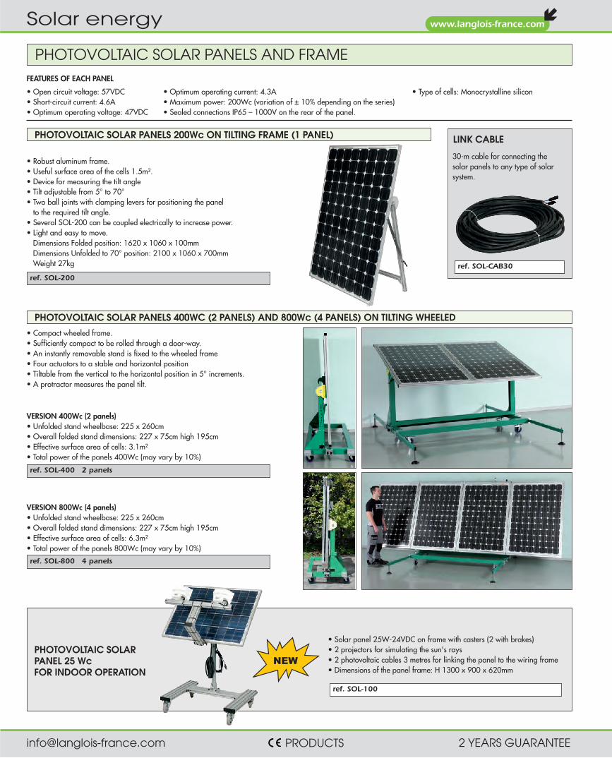
• Robust aluminum frame. • Useful surface area of the cells 1.5m². • Device for measuring the tilt angle • Tilt adjustable from 5° to 70° • Two ball joints with clamping levers for positioning the panel
to the required tilt angle. • Several SOL-200 can be coupled electrically to increase power. • Light and easy to move.
Dimensions Folded position: 1620 x 1060 x 100mm Dimensions Unfolded to 70° position: 2100 x 1060 x 700mm Weight 27kg
VERSION 800Wc (4 panels) • Unfolded stand wheelbase: 225 x 260cm • Overall folded stand dimensions: 227 x 75cm high 195cm • Effective surface area of cells: 6.3m² • Total power of the panels 800Wc (may vary by 10%)
VERSION 400Wc (2 panels) • Unfolded stand wheelbase: 225 x 260cm • Overall folded stand dimensions: 227 x 75cm high 195cm • Effective surface area of cells: 3.1m² • Total power of the panels 400Wc (may vary by 10%)
• Open circuit voltage: 57VDC • Short-circuit current: 4.6A • Optimum operating voltage: 47VDC
• Optimum operating current: 4.3A • Maximum power: 200Wc (variation of ± 10% depending on the series) • Sealed connections IP65 – 1000V on the rear of the panel.
• Type of cells: Monocrystalline silicon
• Compact wheeled frame. • Sufficiently compact to be rolled through a door-way. • An instantly removable stand is fixed to the wheeled frame • Four actuators to a stable and horizontal position • Tiltable from the vertical to the horizontal position in 5° increments. • A protractor measures the panel tilt.
ref. SOL-400 2 panels
ref. SOL-200
ref. SOL-800 4 panels
ref. SOL-CAB30
LINK CABLE
30-m cable for connecting the solar panels to any type of solar system.
FEATURES OF EACH PANEL
PHOTOVOLTAIC SOLAR PANELS AND FRAME
PHOTOVOLTAIC SOLAR PANELS 200Wc ON TILTING FRAME (1 PANEL)
PHOTOVOLTAIC SOLAR PANELS 400WC (2 PANELS) AND 800Wc (4 PANELS) ON TILTING WHEELED
ref. SOL-100
• Solar panel 25W-24VDC on frame with casters (2 with brakes) • 2 projectors for simulating the sun's rays • 2 photovoltaic cables 3 metres for linking the panel to the wiring frame • Dimensions of the panel frame: H 1300 x 900 x 620mm
PHOTOVOLTAIC SOLAR PANEL 25 Wc FOR INDOOR OPERATION

[email protected] PRODUCTS 2 YEARS GUARANTEE
www.langlois-france.com
Solar energy
Practical works • Course on the different technologies of solar panels
(Monocristalline, Polycristalline, Amorphous) • Study on the positioning of solar panels for maximum efficiency. • Study of solar irradiation. • Reminder on Direct, Diffused and Reflected solar radiation. • Comparison of the reading powers with fixed panels and tracking panels. • Study and creation of the wiring of a solar energy system in isolated site. • Reading the currents and voltage at different points of the wiring. • Interpret measurements and calculate efficiency. • Calculation of the battery discharge time according to the load.
SOLAR TRACKER WITH BATTERY
Comprises • 2 solar panels 30W-12V Monocrystalline. • 1 azimuth rotation motor of 160° maximum, that is more than 5 hours of tracking
in position perpendicular to the sun. • 1 zenith rotation motor 43° allowing a complete follow-up of the sun elevation. • 1 set of solar cells. • 1 cabinet with door. • 1 Solar load regulator 12V/ 15A Bluetooth®. • 1 battery 12V-8Ah. • 1 output 12VDC-60W max available on 4mm terminal. • Protection with gPV cartridge fuse. • Emergency stop and switch + 'on' indicator light. • 1 screen printed side with 4 BNC plugs. • 1 artificial solar source mounted on a telescopic stand.
Features • 3-metre mains lead for the artificial source. • Dim.: 1100 x 600 x (H) 1600mm. Weight: 64kg. • The pole and the panels are easy to remove for going through doorways.
The solar tracker is a technical innovation for tracking the sunlight, in order to increase the yield of photovoltaic panels. The productivity gain can reach 40% with a 2-axis tracking system. TRACSOL is a teaching solution for learning this technique. Equipped with 2 axes and 4 cells for automatic sunlight tracking of the sun, it is com-pletely self-contained. No 230V mains connection is required. Only the artificial solar source enabling TRACSOL to be used indoors is powered with 230VAC. The transparent sides of the mechanical box enclosing the two axes provide a full view of the chain drive linkages. 4 BNC fixed on the front of the cabinet allow the oscilloscope reading of the signals generated by the 4 solar cells. The voltage of the solar panels is available on the two safety terminals. The assembly is mobile thanks to 4 heavy-duty wheels attached under the frame.
• Study and comissioning a solar tracker. • Understand how solar cells work. • Master the wiring of the components of an installation photovoltaic
in isolated site. • Perform measurements using an oscilloscope and ammeter clamp
not supplied). • Set up a Bluetooth® connection.
EDUCATIONAL OBJECTIVES
TEACHING RESOURCES STUDENT & TEACHER
ref. TRACSOL Bluetooth®
Requires download in Play Store or Apple Store the free application “Victron Energy”. Display on tablet or Smartphone: - Voltage – Current of the panel / Power (W) - Voltage – Current of the battery / Charge current - On-Off state charge Sm
artp
hone
not
sup
plie
d
ref. DC10
SIMULATION OF A SOLAR PANEL
SOL-1
SOL-2
SOL-3
SOL-4-EXP
SOL-5-EXP
SOLPUITS
SOLHAB
Given that photovoltaic panels do not produce significant power in cloudy conditions, it is not possible to complete the related tutorials. DC10 is a source which, by replacing the solar panels, overcomes unpredictable sunshine. • Mains input 230V single-phase • Stop/start switching Push-button + LED indicator lights • Emergency stop Key operated • DC output Adjustable from 0 to 230V DC • Maximum current 10A • Filtering 5% of residual ripple at 10A. • Adjustment method Button on the top • Display of outputs 1 voltmeter and 1 ammeter • Output terminals in parallel 2 photovoltaic type connectors
2 4mm safety terminals • Upstream protection By fuse • Output protection By circuit breaker • Protection of individuals By safety isolation transformer • Dimensions/Weight 330 x 280mm height 510mm/49kg • Castors 4 including 2 with brakes
Supplied with cable (1m) for connection to the management system of photovoltaic panels.
Suitable for indoor operation with our products.

[email protected] PRODUCTS 2 YEARS GUARANTEE
www.langlois-france.com
Solar energy
This source for getting around the loss of sunlight by illuminating the solar panel with artificial light whose spectrum is close to sunlight. While not having as much luminosity as unclouded sunlight, it illuminates with sufficient intensity for the panel to generate 1/3 of its peak power Wc (corresponding to sunlight at 1kW/m²). The solar panel can be removed easily in order to replace a spotlight quickly if necessary. The unit located on the back of the spotlights panel includes • a key-operated emergency stop button for cutting the electricity supply to the spotlights • a digital thermometer shows the temperature at the surface of the solar panel. Accuracy 1°C. • a potentiometer for lighting adjustment, by dimmer built into the unit • a flow control for the forced ventilation • automatic power supply cut-off to the spotlights in the event of abnormal temperature rise of
the solar panel
Ventilation system with protection grid.
SOL-ECO2, protection by bounded safety zone
ELECTRICAL FEATURES OF THE SOLAR PANEL AT 25°C
ARTIFICIAL SOLAR SOURCE
The versions SOL-ECO2 and SOL-ECO2-N have no lateral protection, no forced ventilation. Versions delivered with 4 poles and 2 chains for the delimitation of a safety zone around the system.
Special characteristics for SOL-ARTI2 et SOL-ARTI2-N Two opaque side panels prevent the accidental blinding of a stu-dent. With the solar panel and spotlight support they also make a closed duct for evacuating heat by an air current going from bot-tom to top. Centrifugal fans, located in the bottom part, inject fresh air that runs up the panel. Grids in the bottom and top parts let the air flow pass evacuating the heat, and prevent accidental contact by hand with a burning spotlight or with the fan blades.
REF Photovoltaic panel delivered installed
Side protection against the direct access to the
lamps
Forced ventilation to simulate the wind
Poles and chains for zone boundary
SOL-ARTI2 Yes Yes Yes No
SOL-ARTI2-N No Yes Yes No
SOL-ECO2 Yes No No Yes
SOL-ECO2-N No No No Yes
The versions without “installed photovoltaic panels” are compatible with the reference SOL-200 of page 146.
LIGHTING SOLAR ARTIFICIALMaximum power 220Wc 70WcOpen circuit voltage 43V 43VShort-circuit current 6.2A 2.3A
• Sealed connections IP65 – 1000V • Power supply: 230VAC. • Dimensions/Weight: 1228 x 665mm height 1926mm. • 4 casters including 2 with brake
PRACTICAL WORK Adjustment of the light intensity demonstrates the correlation between the light flow and the cur-rent delivered by the photovoltaic panel, at constant voltage. A temperature probe linked to the unit thermometer is located on the solar panel. This shows its instantaneous temperature. Any reduction of the ventilation flow causes the panel temperature to rise, and lowers the photovoltaic current in constant lighting.
[email protected] PRODUCTS 2 YEARS GUARANTEE
www.langlois-france.com
Solar energy
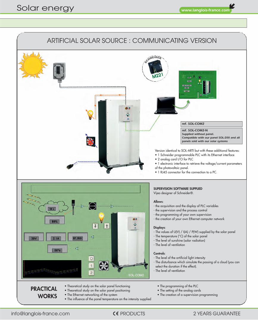
SUPERVISION SOFTWARE SUPPLIED Vijeo designer of Schneider®. Allows: - the acquisition and the display of PLC variables - the supervision and the process control - the programming of your own supervision - the creation of your own Ethernet computer network Displays: - The values of U(V) / I(A) / P(W) supplied by the solar panel - The temperature (°C) of the solar panel - The level of sunshine (solar radiation) - The level of ventilation Controls: - The level of the artificial light intensity - The disturbance which simulate the passing of a cloud (you can
select the duration if the effect). - The level of ventilation
ARTIFICIAL SOLAR SOURCE : COMMUNICATING VERSION
ref. SOL-COM2
ref. SOL-COM2-N Supplied without panel. Compatible with our panel SOL-200 and all panels sold with our solar systems
Version identical to SOL-ARTI but with these additional features: • 1 Schneider programmable PLC with its Ethernet interface • 2 analog card I/O for PLC • 1 electronic interface to retrieve the voltage/current parameters of the photovoltaic panel. • 1 RJ45 connector for the connection to a PC.
• Theoretical study on the solar panel functioning • Theoretical study on the solar panel positioning • The Ethernet networking of the system • The influence of the panel temperature on the intensity supplied
• The programming of the PLC • The setting of the analog cards • The creation of a supervision programming
PRACTICAL WORKS

[email protected] PRODUCTS 2 YEARS GUARANTEE
www.langlois-france.com
Solar energy
This learning panel supports studying a photovoltaic or wind energy source at an isolated site. TAE-ISOL is put on a table. It is equipped with 2 unfolding mobile arms which can move 70° and provide great stability. Dimensions: 700 x 600 x 400mm (unfolded arms). Delivered with a group of 4mm safety leads. Integrated batteries.
• Discover the various elements of a photovoltaic or wind turbine system. • Learn and understand the safety elements present. • Perform activities at different electrical dimensions. • Analyze & interpret the results. • Study the yield and incidence related to the panel positioning. • Study the energy chain (production, storage, utilization, energy behavior). • Wire a photovoltaic or wind facility • Set up a Bluetooth® connection
PEDAGOGICAL OBJECTIVES
TEACHING RESOURCES STUDENT & TEACHER
ref. TAE-ISOL Bluetooth®
This teaching panel must be connected to a PV or wind voltage source. It is compatible with our SOL-200 solar panels and our EOLYS-500 wind power. Input voltage between 24Vdc and 48Vdc maximum.
Requires download in Play Store or Apple Store the free application “Victron Energy”. Display on tablet or Smartphone: - Voltage – Current of the panel / Power (W) - Voltage – Current of the battery / Charge Current - On-Off state charge Sm
artp
hone
not
sup
plie
d
TEACHING PANEL FOR AN ENERGY FACILITY AT AN ISOLATED SITE

[email protected] PRODUCTS 2 YEARS GUARANTEE
www.langlois-france.com
Solar energy
TEACHING PANEL FOR NETWORK INJECTION
You can choose between two types of operation: total return of energy produced or restitution of energy not consumed only. TAE-RES is put on a table. It is equipped with 2 unfolding mobile arms which can move 70° and provide great stability. Dimensions: 770 x 600 x 360mm (unfolded arms). Delivered with a group of 4mm safety cords.
• Discover the various elements of a photovoltaic or wind turbine system. • Learn and understand the safety elements present. • Perform activities at different electrical dimensions. • Analyze & interpret the results. • Study the yield and incidence related to the panel positioning. • Study the energy chain (production, utilization, energy behavior). • Wire a photovoltaic or wind facility
PEDAGOGICAL OBJECTIVES
TEACHING RESOURCES STUDENT & TEACHER
ref. TAE-RES
This worktable must be connected to a PV or wind voltage source It is compatible with our SOL-200 solar panels and our EOLYS-500 wind power. Entry voltagecomprises between 75VCC and 150Vcc.

[email protected] PRODUCTS 2 YEARS GUARANTEE
www.langlois-france.com
Solar energy
STUDY OF FAULT DIAGNOSTICS ON A SOLAR INSTALLATIONSOL-DIAG is a solar model for producing faults at different points of the wi-ring. The assembly is comprised of an aluminium frame on casters, a wiring frame with solar components, a set of switches and a separate photovoltaic panel. The faults can be produced by the instructor by rotating single switches. The voltage of the circuit does not exceed 30VDC. Thus students can take measurements or perform tests in complete safety, regardless of the fault type.
• To learn and understand the operation of a photovoltaic installation.
• To diagnose faults on a photovoltaic installation in isolated site. • To take the measurements of the different electrical values. • Analysing and interpreting the results. • To study the efficiency of the solar panels. • To study the energy system (production, storage, use, energy
performance).
EDUCATIONAL OBJECTIVES
TEACHING RESSOURCES STUDENT & TEACHER
Practical works • Identification of the different components of the energy system. • Producing the electrical diagrams. • Calculation of the efficiency of the photovoltaic panel. • Reading the currents and voltages in the circuit. • Finding the faults on the circuit using measuring devices.
Composition of the model • Frame with casters, two with brakes • One wiring frame equipped with:
1 surge arrester 6 two-pole fuse holders 1 maintenance switch 2 batteries 12VDC-8Ah 1 20A charge regulator with LCD 1 voltage converter 24VDC/230VAC-200VA 2 bulkhead lights, one with 230VAC, the other with 24VDC 1 battery charger 12VDC
• One unit containing 7 switches for creating faults One key operated flap for hiding the switches
• Melamine shelf 750x400mm • Dimensions of the frame: H 1800 x 800 x 700mm
DESCRIPTION OF THE FAULTS
ref. SOL-DIAG
Model supplied wired, operational, with teaching manual on CD. Autonomous power supply. Recharges the batteries using the supplied charger.
Composition of the solar source • Solar panel 25W-24VDC on frame with casters (2 with brakes) • 2 projectors for simulating the sun's rays • 2 photovoltaic cables 3 metres for linking the panel to the wiring frame • Dimensions of the panel frame: H 1300 x 900 x 620mm
Model + Solar source (panel and spotlights) for indoor operation
aref. SOL-DIAG-N Sold without solar panel
Use your own panels with specifications comprises between 18 & 50VDC.
Flap for access to the switches • Marked red
Faults 1/2/4: switch for wire break Fault 3: Insertion of high resistance in series Faults 5/6/7: faults on the 3 inputs of an electronic component inside the charge regulator. The voltages are present on the + and – terminals but the regulator does not work.
• Marked blue Faults 1/2/3/4/5/6: change of fuse with defective one. 6 OS fuses are supplied with the model.
• Marked green Fault 1: change of bulb 24V with a defective one. Defective bulb supplied with the model.

[email protected] PRODUCTS 2 YEARS GUARANTEE
www.langlois-france.com
Solar energy
ref. PYR1307
ref. VA200
Battery info: 8 x LR6
Battery info: 2 x LR03
SOLAR ANALYSER
PYRANOMETER
ref. VA1011
Complete datasheet
www.langlois-france.com
PHOTOVOLTAIC INSTALLATION ANALYZER
The PYR1307 pyranometer measures the power of solar radiation in watts per m2: W/m2 • Ratings: 199.9 W/m2 and 1,999 W/m2 • Measuring error: < 10W/m2 or 5% of the reading • Display: 2,000 pixel LCD • Captures min. and max. values • "Hold" key allows one to freeze the display • Backlighting • Supplied with a carry case • Dimensions: 162 x 63 x 28mm • Weight: 250g
• Current/voltage graph drawing (characteristic of the solar panel)
• Autoscan search of the solar panel maximum power – Pmax (60V – 6A)
• Maximal voltage Vmaxp at Pmax power • Maximal voltage Imaxp at Pmax power • Opened circuit voltage Vopen • Short-circuit opened Ishort • I = f(V) graph with a cursor • Efficiency calculation in % • Power by area unit (in W/m2) • Manual test for a particular point • Range 10V / accuracy 0.001V
Range 60V / accuracy 0.01V Range 1A / accuracy 0.1mA Range 6A / accuracy 1mA Accuracy 1% + 18dgt
Package includes: • bag • AC power • accumulators • cables connecting
panels • USB cable & software.
Professional device for testing, maintaining, troubleshooting and checking the efficiency of solar panels. The VA1011 analyzer measures and displays: • the search for maximum solar energy (Pmax) with the AUTO SCAN function (1000V, 12A) • the maximum voltage (Vmaxp) at Pmax • the maximum current (Imaxp) at Pmax • the open circuit voltage (Vopen) • the short-circuit current (Ishort) • the I / V curve of a panel or set of solar panels. • The efficiency calculation (%) of your installation • Solar radiation as W/m² • The temperature of your solar panel • The series resistance (Rs) of solar panels All these functions are accessible through the software.
Using the amps and watts clamps • P min/max as DC/AC upstream and downstream of the inverter. Digital display and as curves. • U and I min/max as DC / AC upstream and downstream of the inverter. • The power factor as AC. All the readings taken can be saved as easy to recover dated files. 3980 measurements by file.
Scope of supply • 1 portable solar analyzer, power supply by lithium battery with its mains
charger 230V AC 50/60 Hz. Dim: 257x155x57 mm. Weight: 1.55 kg • 1 software + cord for USB link to PC. • 1 amps clamp (direct link to analyzer using specific cord). • 1 watts clamp (direct link to analyzer using specific cord). • 1 solar radiation sensor with its support for attaching to solar panel • 1 temperature sensor for attaching to solar panel. • set of safety and photovoltaic cords. • 1 carrying case. • Detailed instructions with connection diagrams.

[email protected] PRODUCTS 2 YEARS GUARANTEE
www.langlois-france.com
Solar energy
SOLAR CHARGE REGULATOR NETWORK INVERTER VOLTAGE CONVERTER
ref. CIA-BAT24
ref. CIA-REG ref. CIA-OND05 ref. CIA-CONV
BOXED COMPONENTS FOR STUDYING SOLAR ENERGY
SEALED SOLAR BATTERIES LIGHTNING ARRESTER PROTECTION
ref. CIA-PRF
2 x CIA-COM 1 x CIA-PRF 1 x CIA-FUS 4 x SBT-FUS12 1 x CIA-OND05 3 x CIA-CPT 1 x CIA-BORN 1 x CIA-VDE
1 x CHT-V6 (see Page 177) 1 x CIA-SE0 (see Page 182) 2 x CIA-MT37 (see Page 181) 2 x SOL-200 (see Page 146) 1 x SOL-CAB30 (see Page 146)
For instance : set of components
for the study of the wiring of a
solar energy system with energy
release on the electrical network
230 Vac (mains).
6 leads 402S-R (see Page 225) 15 leads 402S-N (see Page 225) 10 leads 402S-B (see Page 225) 2 leads 404S-R (see Page 225) 6 leads 404S-N (see Page 225) 2 leads 404S-B (see Page 225) 4 leads TE-200 (see Page 225)
Tips and wiring diagrams provided
OPTIONS Ref. SOL-200 Photovoltaic panel 200W on tilting
foot with device for measuring the tilt angle (description P.146)
Ref. SOL-CAB30 Connection cable for photovoltaic panels 30m 3G6mm2
(description P.146) Ref. ACQUI-SOL Interface with 3 sensors and acqui-
sition software to read the installa-tion's electrical characteristics. (description P.129).
Ref. DC10 Power supply DC 0 - 220V - 10A protected. Simulates the panels. (description P.147).
Ref. SOL-ARTI2 Source of artificial sunlight. (description P.144)
These components are made safe in plastic boxes with transparent covers. They are perfectly visible and the cabling is facilitated by the different safety terminals Ø4mm. Each box is supplied with detailed instructions
• Lot of 2 sealed solar batteries 12V-12Ah. • Separate cabling of the two sources for putting the
2 batteries in series or parallel. • L x W x h: 280x190x130mm
• Solar charge regulator with LCD. • Max current 20A. • Operating voltage 12V or 24V with automatic
recognition. • Input voltage area from 6.9 to 17.2VDC for
12VDC and from 17.3 to 43VDC for 24VDC. • Front pushbuttons for displaying the voltage and
current of the charge in the battery and in the use circuit.
• Solar panel input 48VDC Max • Minimum battery voltage 6.9V. • L x W x h: 200x200x130mm
• Network inverter 500W. • Automatic synchronization on the network
230VAC-50Hz. • Input voltage from 65 to 130VDC. • Input on safety terminals and output on 2 1-m
cables fitted with safety plugs Ø 4mm male. • Thermal protection integral to the box. • L x W x h: 350x150x60mm
• Pure sine-wave voltage converter 300W. • Input voltage, on safety terminal, from 20 to
32VDC and output 230VAC-50Hz on 2P socket. • Thermal protection integral to the box. • L x W x h: 210x210x70mm
• Lightning arrester protection for 2-pole DC circuit - 500VDC.
• L x W x h: 180x80x90mm

[email protected] PRODUCTS 2 YEARS GUARANTEE
www.langlois-france.com
Solar energy
PHOTOVOLTAIC 2-POLE FUSE HOLDER
MODULAR ENERGY METER PHOTOVOLTAIC SWITCH
PHOTOVOLTAIC INVERTER2-POLE CIRCUIT-BREAKER
INTERFACE FOR SAFETY TERMINALS
ref. CIA-FUS
ref. CIA-CPT ref. CIA-COM
ref. CIA-VDE
ref. CIA-INV
ref. CIA-BORN
SOLAR PUMP 24VDC - 3.5A
ref. CIA-POMP
Option for fast attachment onto an universal rail. In this way, you can attach your various industrial components onto a grid in order to make wiring and testing easier. To order this option, simply add –FIX to the end of the reference Ex : CIA-VDE-FIX
OPTION ACCROCHAGE SUR RAILS
1 x CIA-COM 1 x CIA-BAT24 1 x CIA-PRF 5 x CIA-FUS 12 x SBT-FUS12 1 x CIA-REG 1 x CIA-CONV 1 x CIA-BORN
1 x CIA-MT37 (voir Page 181) 2 x SOL-200 (voir Page 146) 1 x SOL-CAB30 (see Page 146) 15 leads 402S-R (see Page 225) 15 leads 402S-N (see Page 225) 2 leads 404S-R (see Page 225) 2 leads 404S-N (see Page 225) 2 leads TE-200 (see Page 225)
For instance : set of components
for the study of the wiring of a
solar energy system for isolated
site using batteries.
Tips and wiring diagrams provided
• Photovoltaic two-pole fuse holder 10x38mm, • 2-pole for DC. • Fuse replacement without opening box • Max: 1000VDC. • L x W x h: 130x80x90mm • Supplied without fuse cartridges gPV.
Option Fuse gPV 10x38 1000V: Ref. SBT-FUS10
• Single-phase modular energy meter 63A. • Gauges key kW.h/kW/Partial. • Reset key. • Resolution 0.1kW • L x W x h: 170x140x100mm
• Photovoltaic switch 500VDC. • 3-pole – 32A. • Front operation control 90° • Position: O/I • L x W x h: 120x120x100mm
• Two-pole Photovoltaic circuit-breaker with EMS de-fault current in compliance with Standard VDE0126.
• Adjustable without opening box • Gauge 16A-30mA. • Use voltage from 196 to 250VAC • L x W x h: 170x140x100mm
• Photovoltaic inverter switch 500VDC. • 6-pole – 32A. • Front operation control 190° • Position I/O/I • L x W x h: 170x140x100
• Interface unit for converting 2 photovoltaic type terminals into safety terminals 4mm.
• 32A Max. • L x W x h: 105x80x90mm
• Self-priming • Power supply on safety terminals

[email protected] PRODUCTS 2 YEARS GUARANTEE
www.langlois-france.com
Wind turbine energy
EOLYP is a test bench dealing with the study of the hyper synchronous activity of a wind turbine for its electricity production aspects, excluding the mechanical aspects. Due to noise pollution and draughts, which are incompatible with a classroom environment, the propeller has been replaced by a variable speed drive motor. The functional diagram presents the operating principle. The safety components placed in the electrical cabinet are not represented to simplify reading. The propeller, for which the operator adjusts the speed, drives the generator from 0 to 1800 rpm. Two sensors placed on the shaft, returns rotation speed and torque information to the console which displays this information. The generator is coupled to the public three-phase network, through an electrical measurement bench indicating the: • active power injected into the network. • voltage between phases • current • power factor. The central-zero wattmeter shows that depending on the drive speed, the generator consumes or produces energy highlighting the hypersynchronous and hyposynchronous operations. The voltage/current distortion also changes with the rotation speed as indicated by the central-zero power factor meter. The adjustable capacitors battery is used to adjust the power factor to around 1 depending on the speed and power produced.
ref. EOLYP
ref. EOLYP-ECO without sensor and display unit
WIND TURBINE SIMULATOR - NETWORK INJECTION

[email protected] PRODUCTS 2 YEARS GUARANTEE
www.langlois-france.com
Wind turbine energy
ACQUISITION PACK
ref. EOL-COM2
EOL-COM2 is an option for EOLYP and EOLYP-ECO. This option allows recording and plotting on PC the electrical values as voltage, current and power provided to the Electrical network. The software supplied dis-plays these electrical values in real time and collects them in Excel for-mat.
Function U I W
Ranges400Vrms single-phase 700Vrms 3-phase
20Arms 0.2 - 2 - 20kW
Accuracy
in %
of reading
1% from 0 to 70kHz2% 0 ~ 20kHz
3% 20 ~ 70kHz
2% 0 ~ 20kHz
3% 20 ~ 30kHz
5% 30 ~ 70kHz
Protection Electronic breaker 20A delayed fuse
Impedance 1.5MΩ <5mΩRecopy
outputs10VDC/1000Vrms 10VDC/20Arms
10VDC/
0,2kW - 2kW - 20kW
DISPLAY By two displays 2000 pts and one display 2000 pts with LEDS. INPUTS Voltage inputs: Three floating potential voltage terminals, situated at the rear of the apparatus allowing either the application of an alternating, continuous or com-posite voltage, or a balanced three phase voltage. These inputs are electronically protected against over voltages. Max. voltage: 400Vrms single phase, 700Vrms three phase Current inputs: Two floating potential current terminals, situated at the rear of the apparatus allowing the application of an alternating, continuous or composite current. Imax = 20A. The current input is protected by a delay fuse, allowing mea-surements on starting up a motor RECOPY OUTPUTS Voltage output: 0 to 10V DC signal for 0 to 1000Vrms entering. Current output: 0 to 10V DC signal for 0 to 20Arms entering. Power output: 0 to 10V DC for 0 to 0.2kW - 0 to 2kW - 0 to 20kW; these three ratings are switched automatically. Important: these three outputs are insulated from the voltage and currents applied to the input terminals of the apparatus. OTHER CHARACTERISTICS Dimensions of each case : 375 x 80 x 275mm. Weight : 5kg.
During the acquisition, the values of U/I/P are displayed at the same time as curves and numerical values. Connection on PC by a USB cable of 2m (sup-plied). Mains supply: 230Vac – 50/60Hz
Proposed Practical Works • Reminders on the wind turbine functioning. • Synchronization procedure on the electrical network. • Raising the power factor by a capacitors bank and study the results. • Plotting the electrical characteristics of the energy production system. • Calculating the overall efficiency. • Studying of the functioning in an isolated site.
COMPRISES • 1 frame on casters, dim. 1200x750mm height : 1820mm. Weight: 143kg. • 1 asynchronous motor 1.5 kVA • 1 generator • 1 DC tachogenerator / 1 torque sensor • 1 command console • 1 electrical cabinet • 1 network coupling unit
GENERATOR FEATURES • Generator: 3 x 400VAC Asynchronous motor. • Active power injected into the network: 0 to 1.2kVA • Generator efficiency: 78% • Speed variation: 0 to 1800 rpm
ELECTRICAL CABINET FEATURES Inside • 30 mA circuit breakers & thermal-magnetic
and thermal circuit breakers. • 2.2kVA speed controller with control
unit on the console. • stepped capacitors battery On the front • 1 emergency stop circuit breaker • 1 switch disconnector • 1 stop/Start button with push button • 4 switches triggering the capacitors
to rectify the cosϕ • 2 indicator lights show a thermal fault
on the motor and generator
• Understanding the mechanical & electrical principles of a wind turbine. • Studying the hypo-synchronous and hyper-synchronous operating
modes of an asynchronous motor. • Studying the synchronization of the electrical network. • Calculating the efficiency of the energy production system. • Using a clamp-on Ammeter.
EDUCATIONAL OBJECTIVES
TEACHING RESOURCES STUDENT & TEACHER
W V A rpm Nm
GENERATORSensors
Mains
ϕ

[email protected] PRODUCTS 2 YEARS GUARANTEE
www.langlois-france.com
Wind turbine energy
ref. EOLYS-500
Wind turbine features • Three-phase output 3 x 53V AC - 400W at 370 rpm on safety
terminals. • Direct current output 90V DC - 400W at 370 rpm on safety terminals. • Selection of these outputs by using an included rectifier or by direct
connection. Features of the wind simulation • Squirrel-cage three-phase asynchronous motor. • Speed controller simulating wind turbine speed 0-400 rpm. • Using the supplied SOMOVE software, the PC operations are:
- Acceleration of the wind speed. - Deceleration of the wind speed.
General features • Wheeled frame with brakes • Overall dimensions: 750 x 670 x (h) 1500 mm • Top cover made with aluminium frame and Lexan sides
(translucent and unbreakable). • Power supply 2P+N+E 230V AC - 50/60 Hz
(5m lead with mains plug) • Supplied with: Practical assignments in the form of
measurements/tests; RJ45-USB cable for linking between the speed controller and the PC. Schneider® SoMove software.
Supplied with SoMove
EOLYS-500 is a three-phase wind turbine 400W belt-linked to a driven motor that simulates the wind strength. This sys-tem is suited to class room conditions. It perfectly simulates wind turbine operation without noise or draughts since there is no fan. Protected by a transparent cover, the wind turbine can be seen with no risk of direct contact. EOLYS-500 is more than a simulator because it rotates a true three-phase generator and short blades.
THREE-PHASE WIND TURBINE - 400W
W
V
U
L3
L2
L1
N
20V53VAC
3-PHASE DIODES BRIDGE
Transformer 550VA
-
+
Neutral
Phase
VOLTAGE CONVERTER
+
-
Ph
N
VOLTAGE OUTPUT 230VAC / 500VA Max.
CHARGEOL
DC
out
put
AC
out
put
EXAMPLE OF COMPATIBLE LOAD
See page 154
• Understanding the different elements of a wind turbine.
• Make the measurements of electrical parameters (3-phase and continuous).
• Analyzing and interpreting results. • Studying the efficiency and impacts related to the
wind force. • Studying the chain of wind energy (production,
storage, consumption, energetic behavior). • Control and set a speed variator from a PC.
EDUCATIONAL OBJECTIVES
DELIVERED WITH TESTS & PRACTICAL WORKS

[email protected] PRODUCTS 2 YEARS GUARANTEE
www.langlois-france.com
Wind turbine energy
1. WIND TURBINE 400W • SEE opposite EOLYS-500 2. ELECTRICAL CABINET Standard technical cabinet on wheeled frame. Dimensions: 810 x 600 x 1890mm base included. Comprises • 2 disconnectors • 1 500mA -30A RC device • 1 30mA RC device • 1 lightning arrester + fuses • 3 100Wh resolution meters • 1 Mushroom head emergency stop • 1 source inverter • 1 charging controlle. 12/24VDC-20A • 2 batteries 12V-12Ah • 1 set of photovoltaic connectors • 1 500W inverter for network synchronisation • 1 Voltage converter 24VDC/230VAC-200W
Requires download in Play Store or Apple Store the free application “Victron Energy”. Display on tablet or Smartphone: - Voltage – Current of the panel / Power (W) - Voltage – Current of the battery / Charge current - On-Off state charge
Smar
tpho
ne n
ot s
uppl
ied
THREE-PHASE WIND TURBINE UNITS - 400W
• Understanding the different parts of a wind turbine. • Make the measurements of electrical parameters. • Analyzing and interpreting results. • Studying the efficiency and impacts related to the wind force. • Study the chain of wind energy (production, storage,
consumption, energetic behavior). • Wiring of a wind turbine installation. • Set up a Bluetooth connection
EDUCATIONAL OBJECTIVES
• Studying and reading of the electrical features of the wind turbine. • Calculate the system’s efficiency. • Realization of the diagram and wiring for the energy injection on
the electrical network. • Realization of a diagram & wiring for the energy use in an
isolated site. • Download and setup of the Bluetooth application
Proposed practical works
TEACHING RESOURCES STUDENT & TEACHER
Reference EOL-1
When the turbine is stopped, the inverter consumes no current
PARTIAL OR TOTAL RESALE OPERATION In the cabinet, a DC/AC inverter converts the DC current from the turbine into alternating current 220VAC 50Hz and feeds it into the grid in synchronism. This inverter is protected against any polarity reversal and any overload on the DC or AC side. When the wind turbine is stopped, the inverter does not consume any power.
Technical characteristics for the isolated site converter
OPERATION AT ISOLATED SITE The turbine current charges two 12V sealed batteries cabled in series through a charging control-ler. This DC voltage is either available on safety terminals at the rear of the cabinet, or transformed into 250VAC 50Hz voltage by a 300VA voltage converter.
VOLTAGE CONVERTER Voltage Max Current PowerINPUT 20~32 VDC 11AOUTPUT 230VAC 50Hz 1.5A 300VA
INVERTER VOLTAGE Max current Power
INPUT 65~125VDC 8A
OUTPUT 230VAC-50Hz 2,25A 400W
Ref Communicating version Features
EOL1 YES (Bluetooth®) Operation with partial and total resale + at isolated site
EOL2 No Partial or total resale operation only
EOL3 YES (Bluetooth®) Operation at isolated site only
Each reference includes: 1 turbine (Ref. EOLYS-500) + 1 specific electrical cabinet + 1 link cable

[email protected] PRODUCTS 2 YEARS GUARANTEE
www.langlois-france.com
Solar & wind turbine energy
• Discover the different components involved in a wind / solar Hybrid installation. • Perform electrical measurements of different quantities. • Analyze & interpret the results. • Study the efficiency and impacts related to wind strength and sunlight. • Study the energy chain (production, storage, use, energy behavior). • Wire a hybrid wind / solar installation.
EDUCATIONAL OBJECTIVES
TEACHING RESOURCES STUDENT & TEACHER
Travaux pratiques proposés • Record and study of the electrical characteristics of the wind turbine. • Record and study of the electrical characteristics of solar panels. • Calculating the efficiency of the wind / solar hybrid system. • Realization of the diagram and wiring for restitution of the energy
on the electrical grid. • Realization of the diagram and cabling for use of the energy in isolated site.
STATION HYBRIDE SOLAIRE ET EOLIENNE - RESEAU ET SITE ISOLE
Technical characteristic for the inverter coupled to the electrical grid.
PARTIAL OR TOTAL RESALE OPERATION In the cabinet a DC/AC inverter converts the DC from the photovoltaic panels and/or the wind turbine to AC 220VAC 50Hz, and injects its power in synchronism into the electrical grid. This inverter is protected against any polarity reversal and any overload on the DC or AC side. When the panels are not lit, the inverter consumes no current.
Technical characteristics of converter for isolated site.
OPERATION IN ISOLATED SITE WITH NO RESALE The photovoltaic and/or wind turbine current charges two 12V sealed batteries cabled in series through a charge controller. This DC voltage is either available on safety terminals at the rear of the cabinet or converted to 250VAC 50Hz by a 200W voltage converter.
ref. SOLEOL-1 Composition next page
Requires download in Play Store or Apple Store the free application “Victron Energy”. Display on tablet or Smartphone: - Voltage – Current of the panel / Power (W) - Voltage – Current of the battery / Charge current - On-Off state charge
Smar
tpho
ne n
ot s
uppl
ied
SOLAR AND WIND TURBINE HYBRID STATION - NETWORK INJECTION AND ISOLATED SITE
VOLTAGE CONVERTER Voltage Max Current PowerINPUT 20~32 VDC 11A 210WOUTPUT 230VAC 50Hz 1,5A 300VA
INVERTER Voltage Max current Power
INPUT 65~125VDC 8A
OUTPUT 230VAC-50Hz 2,25A 500W

[email protected] PRODUCTS 2 YEARS GUARANTEE
www.langlois-france.com
Solar & wind turbine energy
STATION HYBRIDE SOLAIRE ET EOLIENNE - RESEAU ET SITE ISOLESOLAR AND WIND TURBINE HYBRID STATION - NETWORK INJECTION AND ISOLATED SITE
2 PHOTOVOLTAIC SOLAR PANEL 200WC ON TILTING FRAME (FOR EACH PANEL)
• Open circuit voltage: 57V DC • Short-circuit current: 4.6A • Optimum operating voltage: 47V DC • Optimum operating current: 4.3A • Maximum power: 200Wc (variation of ± 10% depending on the series) • Sealed connections IP65 – 1000V on the rear of the panel. • Type of cells: Monocrystalline silicon • Robust aluminium frame. • Useful surface area of the cells 1.5m². • Output 47VDC – 4.2A – 200Wc per panel on 2 photovoltaic terminals. • Device for measuring the tilt angle • Tilt adjustable from 5° to 70° • Two ball joints with clamping levers for positioning the panel to the required tilt angle. • Light and easy to move.
Folded position: 1620 x 1060 x 100mm Unfolded to 70° position: 2100 x 1060 x 700mm
1. ELECTRICAL CABINET Technical cabinet of standardized solar central unit on wheeled frame. Dimensions: 810 x 600 x 1890mm Comprises • 2 disconnectors • 1 500mA -30A differential • 1 30mA differential • 1 lightning arrester + fuses • 3 100 Wh resolution meters • 1 Mushroom head emergency stop • 1 source inverter • 1 charging controller 12/24VDC-20A • 2 batteries 12V-12Ah • 1 set of photovoltaic connectors • 1 500W inverter for network synchronisation • 1 Voltage converter 24VDC/230VAC-200W
1. LINK CABLE 30-m cable for connecting the solar panels to any type of solar system.
Wind turbine features • Three-phase output 3 x 53V AC - 400W at 370 rpm on safety terminals. • Direct current output 90V DC - 400W at 370 rpm on safety terminals. • Selection of these outputs by using an included rectifier or by direct connection. Features of the wind simulation • Squirrel-cage three-phase asynchronous motor. • Speed controller simulating wind turbine speed 0-400 rpm. • Using the supplied SOMOVE software, the PC operations are:
- Acceleration of the wind speed. - Deceleration of the wind speed.
General features • Wheeled frame with brakes • Overall dimensions: 750 x 670 x (h) 1500 mm • Top cover made with aluminium frame and Lexan sides (translucent and unbreakable). • Power supply 2P+N+E 230V AC - 50/60 Hz (5m lead with mains plug) • Supplied with: Practical assignments in the form of measurements/tests; RJ45-USB cable for linking
between the speed controller and the PC. Schneider® SoMove software.
1 3-PHASE WIND TURBINE 400W

[email protected] PRODUCTS 2 YEARS GUARANTEE
www.langlois-france.com
Solar & wind turbine energy
SOLAR AND WIND TURBINE HYBRID STATION - NETWORK INJECTION
ref. SOLEOL-2 Composition next page
• Understanding the different elements of a photovoltaic and wind turbine system. • Understanding the safety components involved in the system. • Electrical measurements of different parameters. • Analyzing and interpreting results. • Studying the efficiency and impacts related to the positioning of the solar panels. • Studying of the chain of solar energy (production, consumption, resale, energetic behavior). • Wiring of a hybrid system.
EDUCATIONAL OBJECTIVES
TEACHING RESOURCES STUDENT & TEACHER
PARTIAL OR TOTAL RESALE OPERATION In the cabinet a DC/AC inverter converts the DC from the photovoltaic panels or the wind turbine to AC 220VAC 50Hz, and injects its power in synchronism into the network through an isolation transformer. This inverter is protected against any polarity reversal and any overload on the DC or AC side. When the panels are not lit, the inverter consumes no current.
Technical characteristic for the inverter coupled to the public network.
INVERTER Voltage Max current Power
INPUT 65~125VDC 8A
OUTPUT 230VAC-50Hz 2,25A 500W

[email protected] PRODUCTS 2 YEARS GUARANTEE
www.langlois-france.com
Solar & wind turbine energy
SOLAR AND WIND TURBINE HYBRID STATION - NETWORK INJECTION
1. ELECTRICAL CABINET Technical cabinet of standardized solar central unit on wheeled frame. Dimensions: 810 x 600 x 1890mm Comprises • 2 disconnectors • 1 500mA -30A differential • 1 30mA differential • 1 lightning arrester + fuses • 1 Mushroom head emergency stop • 3 100 Wh resolution meters • 1 set of photovoltaic connectors • 1 500W inverter for network synchronisation
2 PHOTOVOLTAIC SOLAR PANEL 200WC ON TILTING FRAME (FOR EACH PANEL)
• Open circuit voltage: 57V DC • Short-circuit current: 4.6A • Optimum operating voltage: 47V DC • Optimum operating current: 4.3A • Maximum power: 200Wc (variation of ± 10% depending on the series) • Sealed connections IP65 – 1000V on the rear of the panel. • Type of cells: Monocrystalline silicon • Robust aluminium frame. • Useful surface area of the cells 1.5m². • Output 47VDC – 4.2A – 200Wc per panel on 2 photovoltaic terminals. • Device for measuring the tilt angle • Tilt adjustable from 5° to 70° • Two ball joints with clamping levers for positioning the panel to the required tilt angle. • Light and easy to move.
Folded position: 1620 x 1060 x 100mm Unfolded to 70° position: 2100 x 1060 x 700mm
1. LINK CABLE 30-m cable for connecting the solar panels to any type of solar system.
Wind turbine features • Three-phase output 3 x 53V AC - 400W at 370 rpm on safety terminals. • Direct current output 90V DC - 400W at 370 rpm on safety terminals. • Selection of these outputs by using an included rectifier or by direct connection. Features of the wind simulation • Squirrel-cage three-phase asynchronous motor. • Speed controller simulating wind turbine speed 0-400 rpm. • Using the supplied SOMOVE software, the PC operations are:
- Acceleration of the wind speed. - Deceleration of the wind speed.
General features • Wheeled frame with brakes • Overall dimensions: 750 x 670 x (h) 1500 mm • Top cover made with aluminium frame and Lexan sides (translucent and unbreakable). • Power supply 2P+N+E 230V AC - 50/60 Hz (5m lead with mains plug) • Supplied with: Practical assignments in the form of measurements/tests; RJ45-USB cable for linking
between the speed controller and the PC. Schneider® SoMove software.
1 3-PHASE WIND TURBINE 400W

[email protected] PRODUCTS 2 YEARS GUARANTEE
www.langlois-france.com
Solar & wind turbine energy
SOLAR AND WIND TURBINE HYBRID STATION - ISOLATED SITE
ref. SOLEOL-3 Composition next page
• Understanding the different elements of a photovoltaic and wind turbine system. • Understanding the safety components involved in the system. • Electrical measurements of different parameters. • Analyzing and interpreting results. • Studying the efficiency and impacts related to the positioning of the solar panels. • Studying of the chain of solar energy (production, storage, consumption, resale, energetic behavior). • Wiring of a hybrid system.
EDUCATIONAL OBJECTIVES
TEACHING RESOURCES STUDENT & TEACHER
Technical characteristics for the isolated site converter
OPERATION IN ISOLATED SITE WITH NO RESALE The photovoltaic or wind turbine current charges two 12V sealed batteries cabled in series through a charging controller. This DC voltage is either available on safety terminals at the rear of the cabinet or converted to 250VAC 50Hz by a 200W voltage converter.
VOLTAGE CONVERTER Voltage Max Current PowerINPUT 20~32 VDC 11A 210WOUTPUT 230VAC 50Hz 1,5A 300VA

[email protected] PRODUCTS 2 YEARS GUARANTEE
www.langlois-france.com
Solar & wind turbine energy
SOLAR AND WIND TURBINE HYBRID STATION - ISOLATED SITE
1. ELECTRICAL CABINET Technical cabinet of standardized solar central unit on wheeled frame. Dimensions: 810 x 600 x 1890mm Comprises • 2 disconnectors • 1 lightning arrester + fuses • 1 Mushroom head emergency stop • 1 charging controller 12/24VDC-20A • 2 batteries 12V-12Ah • 1 set of photovoltaic connectors • 1 Voltage converter 24VDC/230VAC-200W
2 PHOTOVOLTAIC SOLAR PANEL 200WC ON TILTING FRAME (FOR EACH PANEL)
• Open circuit voltage: 57V DC • Short-circuit current: 4.6A • Optimum operating voltage: 47V DC • Optimum operating current: 4.3A • Maximum power: 200Wc (variation of ± 10% depending on the series) • Sealed connections IP65 – 1000V on the rear of the panel. • Type of cells: Monocrystalline silicon • Robust aluminium frame. • Useful surface area of the cells 1.5m². • Output 47VDC – 4.2A – 200Wc per panel on 2 photovoltaic terminals. • Device for measuring the tilt angle • Tilt adjustable from 5° to 70° • Two ball joints with clamping levers for positioning the panel to the required tilt angle. • Light and easy to move.
Folded position: 1620 x 1060 x 100mm Unfolded to 70° position: 2100 x 1060 x 700mm
1. LINK CABLE 30-m cable for connecting the solar panels to any type of solar system.
Wind turbine features • Three-phase output 3 x 53V AC - 400W at 370 rpm on safety terminals. • Direct current output 90V DC - 400W at 370 rpm on safety terminals. • Selection of these outputs by using an included rectifier or by direct connection. Features of the wind simulation • Squirrel-cage three-phase asynchronous motor. • Speed controller simulating wind turbine speed 0-400 rpm. • Using the supplied SOMOVE software, the PC operations are:
- Acceleration of the wind speed. - Deceleration of the wind speed.
General features • Wheeled frame with brakes • Overall dimensions: 750 x 670 x (h) 1500 mm • Top cover made with aluminium frame and Lexan sides (translucent and unbreakable). • Power supply 2P+N+E 230V AC - 50/60 Hz (5m lead with mains plug) • Supplied with: Practical assignments in the form of measurements/tests; RJ45-USB cable for linking
between the speed controller and the PC. Schneider® SoMove software.
1 3-PHASE WIND TURBINE 400W

[email protected] PRODUCTS 2 YEARS GUARANTEE
www.langlois-france.com
Wind turbine energy
EOLYP CONVERTYS
Voltage output 230V-AC / 500VA Max.
W
V
U
L3
L2
L1
N
N
Ph
-
+20V
Voltage converter
3-phase diodes bridge
Transformer
-
+Phase
Neutral
The different electrical protections are not shown on the drawingEOLYS-500 CHARGEOL
ref. CONVERTYS
ref. CHARGEOL
CONVERTYS IS SPECIALLY MADE TO WORK WITH EOLYP CHARGEOL IS SPECIALLY MADE TO WORK WITH EOLYS-500 List of Practical Works achievable with each set: • Principle of functioning • The 3-phase voltage delivered by the wind turbine is galvanically separated by an isolation transformer, and then rectified
by a Graetz bridge. • This DC voltage is transformed by a DC/AC converter in an alternative voltage 230V (50Hz) / 500VA • In case of exceeding of this power, the converter automatically offloads the output, switch on an overload indicator light,
and resets 15 seconds after load reduction.
STUDYING THE CONVERSION OF RENEWABLE ENERGY
TECHNICAL CHARACTERISTICS • The converter's synoptic, printed on the front, facilitates location of the com-
ponents and measurement points. • The three-phase voltage from the wind turbine is applied to CONVERTYS
or CHARGEOL through 4 safety terminals 4mm dia. The wind turbine-to-converter interconnection is made using laboratory leads.
CONVERTYS : Inputs between 375 and 460V three-phase. CHARGEOL : Inputs between 80 and 120V three-phase.
• A main switch located on the top of the box, starts and stops the converter's power supply.
• Safety terminals 4mm diam. located between each component enable the voltages and currents to be measured at each conversion step.
• A thermal-magnetic circuit-breaker protects the transformer primary against any overload.
• Output converter 500W/230V. • A differential circuit-breaker 30mA protects the output to the use network
cabled according to neutral system TT. • Unit on casters dimensions: 700 x 500mm. Height 355mm
These converters operate on the same principle as an industrial model. They treat the electrical power supplied by a wind turbine. The output cannot be synchronized with the network but can be used in isolated site.
Proposed Practical Works • Understanding of the wiring diagram. • Sizing of the electrical components related to the voltage and the power. • Reading of currents and voltage in different points of the circuit. • Calculation of powers. • Calculation of electrical efficiencies.
• Study of the conversion of the electrical energy from 3-phase to single-phase.
• Make some measurements with a clamp-on ammeter.
EDUCATIONAL OBJECTIVES
TEACHING RESOURCES STUDENT & TEACHER

[email protected] PRODUCTS 2 YEARS GUARANTEE
www.langlois-france.com
Energy saving
Features of the base • Base on large wheels • easy to move. • Dim. L x W x H: 1500 x 750 x 1980mm • Melamine surface: 1200 x 1700mm
• Panel supplied with a full wiring diagram and all of the detailed instructions for each component.
• The items on the panel may be different from one series to another depending on manufacturer alterations.
ICO cables (placed between the 2 melamine plates that the panel com-prises) connect the components together
Components located on the panel • 1 watt-hour meter displaying: The total power consumed for tariff 1 and 2. The partial power consumed for tariff 1 and 2. The instantaneous active power consumed. The max. active power for tariff 1 and 2. • 1 500mA mains installation residual current circuit breaker at the front of the unit, after
the meter. • 1 modular table consisting of: 1 circuit breaker protection set, including 1 30mA residual current type. 1 adjustable cut-off device with 2 secondary circuits 9 modules with 4mm safety terminals, including: - 7 for measuring currents - 2 for measuring voltages (mains and low-voltage). • 4 lighting circuits with fitted circuit breaker for an 18W fluorescent tube for a wall light with a 100W incandescence light bulb for a wall light with a 20W energy-efficient light bulb for a 50W low-voltage spotlight • 3 heating circuits with two 1000W convectors. a 600W radiant.
ref. ECODOM-C Wiring version
HOME ENERGY USE PANEL
Practical works • Measuring instantaneous consumption and consumption over time using the watt-hour
meter. • Varying consumption according to usage between two periods • Distributing power consumption between two tariffs • Managing overconsumption (watt-hour meter and load shedding) • Measuring the two voltages available on the panel • Measuring the current using modules fitted with safety terminals (Without modification,
currents are measured using a standard ammeter or a hook-on ammeter).
• Understanding of the energy metering, intensities, load shedding and the comfort under control of lighting circuits and heating a home, with the same consumption than an apartment.
• Achieving the measure of electrical quantities. • Analyzing and interpreting the results.
EDUCATIONAL OBJECTIVES
TEACHING RESOURCES - 7 PW

[email protected] PRODUCTS 2 YEARS GUARANTEE
www.langlois-france.com
Energy saving
AUTOMATIC LEAK ALERT SYSTEM
Features • Dimensions of the frame
MAQ-FUITE-A version: 370 x 230 x 1005mm. MAQ-FUITE version: 370 x 230 x 700mm.
• Technical cabinet dimensions: 330 x 200 x 440mm • Total weight, frame + cabinet
MAQ-FUITE-A version: 25kg. MAQ-FUITE version: 19 kg
• Mains power supply 230V + E with 3-metre lead • Requires phone SIM card with subscription or prepaid.
Composition of the sytem • 1 tank, 5 litres (for the MAQ-FUITE-A version) • 1 pump 24VDC – 3.5A (for the MAQ-FUITE-A version) • 1 quick connector for water inlet (for the MAQ-FUITE version) • 1 water meter • 1 pulse sensor attached to the meter • 1 solenoid valve 24V • 1 valve for creating a water leak • 1 valve for cutting off the water inlet • 1 unit with connector for linking to the technical cabinet
A leak of water can be very costly and statistics show that this fault is common at all distribution points. This model represents the drinking water supply circuit of a house equipped with a leak detection system and GSM alert device. When the house is declared unoccupied, a sensor, connected to the water meter, detects the slightest abnormal consumption. A GSM phone trans-mitter then sends an SMS to warn you of the problem. The assembly is managed by a ZELIO logic module. Practical works
• Configuration and installation of the water leak sensor • Configuration of the GSM phone transmitter and test with mobile
phone • Creation of the ZELIO logic module programmes with or without
presence in the home, with or without solenoid valve control.
• Learning about water leak detection by sensor. • Using a GSM phone transmitter • Using and programming a ZELIO logic module
Composition of the technical cabinet • 1 set of magneto-thermal and RC protection devices. • 1 modular power supply 24VDC. • 1 ZELIO logic module • 1 GSM transmitter • 1 set of switches, emergency stop and indicator lights
EDUCATIONAL OBJECTIVES
TEACHING RESOURCES STUDENT & TEACHER
ref. MAQ-FUITE-A
Fully self-contained version thanks to its tank and pump 24V. Requires no water inlet. Lenght of the base 1005mm.
ref. MAQ-FUITE
Version with no pump or tank. Requires a pressurized water inlet in the room. Lenght of the base 700mm.
PULSE WATER METERref. CHT-EAU
Water meter equipped with 2-wire pulse transmitter for remotely sending informa-tion relating to the water meter. Ratio K = 1 - 1 meter unit equal to 1 pulse. Connection to the water circuit using 2 quick connectors (not supplied).

[email protected] PRODUCTS 2 YEARS GUARANTEE
www.langlois-france.com
Energy saving
SPEED CONTROLLER USED FOR ENERGY SAVING
TEACHING RESOURCES STUDENT + TEACHER
ref. MAQ-WATT
Features • Three-phase mains lead 400V 3 metres long for power supply. • Dimensions: 600 x 800 x h 1400mm. Weight: 85kg.
Comprises • Wheeled frame. • One surface pump 750W – three-phase 400VAC. Self-priming and protected against
dry running. • A 30-litre water tank makes the model self-contained. • A manual valve for regulating the water flow. • A float flow rate indicator. • A cabinet with top engraved showing the diagram of operation of the system. • A set of magneto-thermal and RC protection devices. • A set of switches and indicator lights to select the type of operation required. • An energy measuring unit with display of P/Q/S/I/U/V/Cosphi. • Speed controller with software. 1500W – three-phase 400VAC.
Offset control box for controlling the controller from the top of the cabinet. • 3 safety sockets are available at the output of the speed controller for the connection of
your own pump or any other load as a fan (3x 400V / 1.5kW max.)
In a pumping or ventilation installation, the motor, supplied direct from the mains, rotates at its nominal speed. The flow rate can be regulated with manual valve or speed controller. The speed controller enables significant electricity savings to be made, which is not the case of the manual valve. MAQ-WATT demonstrates this phenomenon by comparing the consumption in the two situations. 2 types of operation are offered: • Direct supply of the pump with a contactor and regulation of the water flow with manual
valve. • Supply of the pump with controller and regulation of the flow rate by variation of the
speed of rotation. A measuring unit compares, among other things, the 2 powers absorbed. A float provides a visual indication of the flow rate.
Practical works • Configuration of the speed controller with software. • Configuration of the energy measuring unit. • Comparison of energy consumption. • Calculation of the cost of depreciation of the speed controller. • Reading and plot of the electrical characteristics.
• Energy savings by speed controller demonstrated. • Creation of the configuration of a speed controller with software. • Using an energy measuring unit. • Using a clamp ammeter.
EDUCATIONAL OBJECTIVES