
OMI-2 - optical machine interface - 5MP EU
33
Installation and user’s guide H-2000-5233-03-A OMI-2 - optical machine interface
-
Upload
khangminh22 -
Category
Documents
-
view
1 -
download
0
Transcript of OMI-2 - optical machine interface - 5MP EU

Installation and user’s guide H-2000-5233-03-A
OMI-2 - optical machine interface

© 2005–2009 Renishaw plc. All rights reserved.
This document may not be copied or reproduced in whole or in part, or transferred to any other media or language, by any means, without the prior written permission of Renishaw.
The publication of material within this document does not imply freedom from the patent rights of Renishaw plc.
Disclaimer
RENISHAW HAS MADE CONSIDERABLE EFFORTS TO ENSURE THE CONTENT OF THIS DOCUMENT IS CORRECT AT THE DATE OF PUBLICATION BUT MAKES NO WARRANTIES OR REPRESENTATIONS REGARDING THE CONTENT. RENISHAW EXCLUDES LIABILITY, HOWSOEVER ARISING, FOR ANY INACCURACIES IN THIS DOCUMENT.
Renishaw part no: H-2000-5233-03-A
Issued: 04.09
Trademarks
RENISHAW® and the probe emblem used in the RENISHAW logo are registered trademarks of Renishaw plc in the UK and other countries.
apply innovation is a trademark of Renishaw plc.
All other brand names and product names used in this document are trade names, service marks, trademarks, or registered trademarks of their respective owners.

1Contents
Contents
EC declaration of conformity . . . . . . . . . . . . . . . .2
FCC declaration (USA) . . . . . . . . . . . . . . . . . . . .3
Safety . . . . . . . . . . . . . . . . . . . . . . . . . . . . . . . . .3
Introduction . . . . . . . . . . . . . . . . . . . . . . . . . . . . .5
Mounting bracket . . . . . . . . . . . . . . . . . . . . . . . . .6
OMI-2 visual diagnostics . . . . . . . . . . . . . . . . . . .7
OMI-2 outputs . . . . . . . . . . . . . . . . . . . . . . . . . . .9
OMI-2 output waveforms . . . . . . . . . . . . . . . . . .12
Switches SW1, SW2 and start input . . . . . . . . .14
Switch SW1 output configuration . . . . . . . . . . . .14
Switch SW2 output configuration . . . . . . . . . . . .15
Wiring diagram . . . . . . . . . . . . . . . . . . . . . . . . .16
Installation with inspection and tool setting probe . . . . . . . . . . . . . . . . . . . . . . . . . . . . . . . . .17
Remote external audible output . . . . . . . . . . . . .17
OMI-2 cable . . . . . . . . . . . . . . . . . . . . . . . . . . . .18
OMI-2 cable sealing . . . . . . . . . . . . . . . . . . . . .18
Fitting flexible conduit . . . . . . . . . . . . . . . . . . . .19
Removing the OMI-2 window . . . . . . . . . . . . . .20
Removing the OMI-2 label . . . . . . . . . . . . . . . . .21
Refitting the OMI-2 label . . . . . . . . . . . . . . . . . .21
Changing the reception range . . . . . . . . . . . . . .22
Fitting the OMI-2 window . . . . . . . . . . . . . . . . . .23
Screw torque values . . . . . . . . . . . . . . . . . . . . .24
Fault-finding . . . . . . . . . . . . . . . . . . . . . . . . . . . .25
Parts list . . . . . . . . . . . . . . . . . . . . . . . . . . . . . . .29

2
EC DECLARATION OF CONFORMITY
Renishaw plc declares that the product:
Name: OMI-2
Description: Optical machine interface
has been manufactured in conformity with the following standard:
BS EN 61326-1:2006 Electrical equipment for measurement, control and laboratory use – EMC requirements .
Immunity to table 2 – industrial locations . Emissions to class A – industrial locations .
BS EN 60825-12:2004 Safety of laser products - Part 12: Safety of free space optical communication systems used for transmission of information .
and that it complies with the requirements of directives:
2004/108/EC Electromagnetic compatibility
2006/95/EC Low voltage
The above information is summarised from the full EC declaration of conformity . A copy is available from Renishaw on request .
c

3
FCC DECLARATION (USA)
FCC Section 15.19This device complies with Part 15 of the FCC rules . Operation is subject to the following two conditions:
1 . This device may not cause harmful interference .
2 . This device may accept any interference received, including interference that may cause undesired operation .
FCC Section 15.105This equipment has been tested and found to comply with the limits for a Class A digital device, pursuant to Part 15 of the FCC rules . These limits are designed to provide reasonable protection against harmful interference when the equipment is operated in a commercial environment .
This equipment generates, uses, and can radiate radio frequency energy and, if not installed and used in accordance with the instruction manual, may cause harmful interference to radio communications .
Operation of this equipment in a residential area is likely to cause harmful interference, in which case you will be required to correct the interference at your own expense .
FCC Section 15.21The user is cautioned that any changes or modifications not expressly approved by Renishaw plc or authorised representative could void the user’s authority to operate the equipment .
SAFETY
Information for the user
Beware of unexpected movement . The user should remain outside of the full working envelope of probe head/extension/probe combinations .
Handle and dispose of batteries in accordance with the manufacturer’s recommendations . Use only the recommended batteries . Do not allow the battery terminals to contact other metallic objects .
In all applications involving the use of machine tools or CMMs, eye protection is recommended .
Refer to the machine supplier’s operating instructions .
Information for the machine supplier
It is the machine supplier’s responsibility to ensure that the user is made aware of any hazards involved in operation, including those mentioned in Renishaw product documentation, and to ensure that adequate guards and safety interlocks are provided .
Under certain circumstances the probe signal may falsely indicate a probe seated condition . Do not rely on probe signals to stop the machine’s movement .

4
WarrantyEquipment requiring attention under warranty must be returned to your supplier . No claims will be considered where Renishaw equipment has been misused, or repairs or adjustments have been attempted by unauthorised persons .
Care of the OMI-2Keep system components clean and treat the OMI-2 with care .
Do not apply labels to the front of the OMI-2 .
Changes to equipmentRenishaw reserves the right to change specifications without obligation to change equipment previously sold .
Weight OMI-2 including 8 metres (26 ft) of cable = 1000 g (35 oz) .
OMI-2 including 15 metres (49 ft) of cable = 1500 g (53 oz) .
SealingThe unit is fully sealed to IPX8 .
CNC machineCNC machine tools must always be operated by competent persons in accordance with manufacturer’s instructions .
TemperatureThe OMI-2 is specified for storage over –10 °C to 70° C (14 °F to 158° F) and operation over 0 °C to 60 °C (32 °F to 140 °F) ambient temperature range .
Patent noticeFeatures of products shown in this guide, and of related products, are the subject of the following patents and/or patent applications:
EP 0974208 US 6,839,563 B1
EP 1503524 B

5
Introduction
OMI-2
The OMI-2 is a combined optical receiver and machine interface that is designed to be mounted within the machine’s working envelope .
The OMI-2 operates using a ‘Modulated’ optical transmission mode and is compatible with machine probes that also operate in ‘Modulated’ mode .
Power supply
The OMI-2 can draw its supply from the CNC machine’s 12 Vdc to 30 Vdc supply . Alternatively, power may be supplied from a Renishaw PSU3 power supply unit . The maximum supply current is 40 mA and the maximum current is 200 mA during a START signal .
CAUTION: This equipment will only perform to specification if the power supply 0 V is connected to the machine ground (star point) .
!
40 (1 .57)
84 (3 .30)
40 (1 .57)
40 (
1 .57
)
46 .7 (1 .84)
45 (
1 .77
)
63 (
2 .48
)
16 (0 .63)
dimensions mm (in)
Contact Renishaw for cable rear exit version
Input voltage ripple
The input voltage ripple must not cause the voltage to fall below 12 V or rise above 30 V .
Introduction

6 Mounting bracket
Mounting bracket (optional) dimensions mm (in)
3 holes Ø6 .4 (0 .25)
25 (0 .98)
25 (0 .98)
19 (
0 .75
)
38 (
1 .50
)
45
(1 .7
7)
25
(0 .9
8)30
(1
.18)
3 grip protrusions
100 .5 (3 .95)
90 (3 .54)
2 .0 (0 .08)
2 .0 (0 .08)
3 pairs of holes Ø5 .3 (0 .20) permit OMI-2 mounting in alternative orientation
45 (1 .77) 45°
NOTE: Install the OMI-2 with the cable exiting from the lower side for good coolant run-off . The mounting bracket cannot be used with an OMI-2 in rear exit configuration .

7OMI-2 visual diagnostics
OMI-2 visual diagnostics
A visual indication of system status is provided by LEDs . Indication is provided for START, LOW BATTERY, PROBE STATUS, ERROR and SIGNAL CONDITION .
1. LED (yellow) – START signal status
Lit when a START signal is transmitted to the probe .
This LED will either flash once when a machine-controlled START signal is commanded, or flash at one second intervals when the system is set to ‘Auto-Start’ mode and is waiting for a probe transmission signal .
2. LED (red) – LOW BATTERY
When the OMP battery voltage falls below a set level, the low battery output device changes state and causes the LOW BATTERY LED to be lit .
Replace the OMP battery as soon as practicable after the LED is lit .
KEEP THE WINDOW CLEAN
1 2 3 4 5
Magnetic label
A summary of OMI-2 LED activity is provided on a magnetic label . The label may be placed on any machine flat metal surface .

8 OMI-2 visual diagnostics
3. LED (green, red) – PROBE STATUS
This bi-colour LED is lit when the OMI-2 is powered .
Green – Probe is seated .
Red – Probe is triggered or an error has occurred .
The change of colour of this LED will coincide with the probe status output device’s changing state .
4. LED (red, blue, yellow, violet) – ERROR
Indicates transmission error condition, e .g . optical beam obstructed/probe out of optical range/probe switched off/battery dead .
Red – The signal from the probe has either failed or stopped .
Blue – A second modulated signal is being received .
Yellow – Interference or a weak probe signal is being received .
Violet – Interference or a weak probe signal has caused the trigger instant to be delayed .
NOTE: If the ERROR SSR is activated because the blue or yellow condition causes the loss of a good probe signal, or the violet condition occurs, then the indication persists until the Machine Start is activated or one hour has elapsed .
5. LED (red, yellow, green) – Infrared SIGNAL CONDITION received from probe
As long as there is power to the system, this LED will always be lit . It is a tri-colour LED and indicates as follows:
Red – There is no signal from the probe .
Yellow – Either the signal received from probe is too weak or interference is present .
Green – The condition of the signal received from the probe is good .

9OMI-2 outputs
OMI-2 outputs
There are five outputs:
Probe status 1 (SSR)
Probe status 2a (5 V isolated driven skip)
Probe status 2b (driven at power supply voltage)
Error (SSR)
Low battery (SSR)
All outputs can be inverted by using switches SW1 and SW2 – see page 14 .
Probe status 1, Error, Low battery (SSR)
‘On’ resistance = 50 ohms max .
Load voltage = 40 V max .
Load current = 100 mA max .
Switching times
Open to closed = 100 µs max .Closed to open = 25 µs max .
Probe status 2a (5 V isolated driven skip)
Load current = 50 mA max .
Output voltages
Sourcing = 4 .5 V min at 10 mA . = 2 .4 V min at 50 mA .
Sinking = 0 .4 V max at 10 mA . = 1 .3 V max at 50 mA .
Switching times
Low to high = 20 µs max .High to low = 10 µs max .

10 OMI-2 outputs
Probe status 2b (driven at power supply voltage)
Load current = 50 mA max .
Output voltages
Sourcing (voltage supply – output voltage)
= 2 .6 V max at 10 mA . = 3 .5 V max at 50 mA .
Sinking = 2 .0 V max at 10 mA . = 2 .9 V max at 50 mA .
Switching times
Low to high = 10 µs max .High to low = 10 µs max .
The Low Battery, Probe Status, and Error LEDs will start flashing red when an output overload has occurred . All outputs will be switched off . If this occurs, turn off the power supply and remove the source of the problem . Turning on the power supply will reset the OMI-2 .

11OMI-2 outputs
CAUTION: Power supply voltage Do not exceed 30 V between the black wire and the screen wire (green/yellow), or the red wire and the screen wire (green/yellow), or the red and black wires (power supply), as this could result in permanent damage to the OMI-2 and/or the customer’s power supply . The use of in-line fuses at the machine cabinet end is recommended to provide protection for the OMI-2 and cable . Screen connection A good connection should be made to machine ground (star point) . Output Ensure that outputs from the OMI-2 do not exceed specified current ratings .
!

12 OMI-2 output waveforms
OMI-2 output waveforms
Probe switch
on
Seated
Power off
Probe trigger
Triggered
Probe reseat
SeatedError
e .g . low signal
Error clear
SSR closedNormally open
Probe switch
offLow
battery
PROBE
PROBE STATUS 1 (LEVEL)
OMI-2 SSR/driven
outputs
Normally open
PROBE STATUS 1 (PULSED)
Normally closed
ERROR
Outputs can be inverted by switches – see page 14 .
SSR open
SSR open
SSR open
SSR closed
SSR closed

13OMI-2 output waveforms
Normally open
PROBE
LOW
BATTERY
OMI-2 SSR/driven
outputs
Normally low
PROBE STATUS 2a/2b
(LEVEL)
Normally low
PROBE STATUS 2a/2b
(PULSED)
Probe switch
on
Seated
Power off
Probe trigger
Triggered
Probe reseat
SeatedError
e .g . low signal
Error clear
Probe switch
offLow
battery
SSR open
Output high
Output high
SSR closed
Output low
Output low
SIGNAL DELAYS
1. Transmission delay. Probe trigger to output change of state = 1 .3 ms max .
2. Start delay . Time from initiation of start signal to valid signal transmission = 410 ms max .
NOTE: Pulsed outputs are 40 ms ±1 ms duration .

14 Switches SW1, SW2 and start input
To gain access to the switches, remove the OMI-2 window
Switches SW1, SW2 and start input
N/C
ON
LOW BATTERY
N/C
Pulsed N/O
Level
ERROR
N/C
PROBE STATUS 1
SW1 SW2
N/O = Normally OpenN/C = Normally Closed
Switch SW1 output configuration
Factory settings shown are for:
A-5191-0049A-5191-0050
CAUTION: Exercise caution when using error SSR in N/O mode, as a wiring fault could cause loss of error condition and therefore could result in a non-fail safe condition .
!
CAUTION: Only qualified persons should adjust switches .!
N/O N/O

15Switch SW2 output configuration
MACHINE START
PulsedNormally
high
PulsedNormally low
STARTSTART RANGE
100%
ON
Machine
PROBE STATUS 2a/2b
Level
Auto start
‘Auto start’ selection causes the system to send a START signal at one second intervals, and should only be used when there is no available output from the machine control . In this mode, ensure start signals cannot be received by probes in the tool changer or on other machines .
Machine start
‘Machine start’ is configurable as a level or pulsed signal .
Level 10 V – 30 V (2 .4 mA at 24 V)
When input is active, the probe is switched on .
Pulsed 12 V – 30 V (10 mA at 24 V)
The probe toggles from being switched on/off . The minimum pulse width is 10 ms .
Machine start wires
White = positiveBrown = negative
Switch SW2 output configuration
Factory settings shown are for:
A-5191-0049A-5191-0050
Level Auto 50%

16 Wiring diagram
CAUTION: The power supply 0 V should be terminated at the machine ground (star point) . If a negative supply is used, then the negative output must be fused .
Wiring diagram (with the output groupings shown)
12 V to 30 V
Turquoise
Turquoise/black
Violet
Violet/black
Green
Green/black
White
Brown
Screen
OMI-2
5 VDriver
Driver
Yellow
Grey
Orange
Red
Black
Green/yellow Machine ground (star point)
Power supply (12 V to 30 V)
Probe status 1 (SSR)
Low battery (SSR)
Error (SSR)
Machine start input
Probe status 2a
(5 V isolated driven skip)
+ve
–ve
Signal
Return
Probe status 2b (driven at power supply voltage)
!
0 V

17Inspection and tool setting probe/Remote external audible output
Installation with inspection and tool setting probe
On machines where the OMI-2 is to be integrated with a tool setting probe input, and only one probe input is provided on the control, an M code can be utilised to drive an external relay that will select which probe is monitored .
Remote external audible output
Any one of the probe status outputs can be used to drive an external audible indicator when set to pulsed – see section “OMI-2 outputs” .
NOTE: Audible indicator operation is not possible if both skip drives are being monitored by the control .
CONTROL
PROBE INPUT
M CODE
Probe status from OMI-2
Probe status from tool setter
RELAY

18 OMI-2 cable/OMI-2 cable sealing
OMI-2 cable
Cable termination
A ferrule should be crimped onto each cable wire for more positive connection at the terminal box .
Standard cable variants
The OMI-2 standard polyurethane cables are 8 m (26 ft) and 15 m (49 ft) long .
Contact Renishaw for other cable lengths .
Cable specification
Ø7 .5 mm (0 .29 in), 13 core screened cable, each core 18 x 0 .1 mm .
NOTE: The maximum length of the specified cable must not exceed 25 m (82 ft) .
OMI-2 cable sealing
Coolant and dirt are prevented from entering the OMI-2 by the cable sealing gland . The OMI-2 cable can be protected against physical damage by fitting flexible conduit if required .
Recommended flexible conduit is AnametTM Sealtite HFX (5/16 in) polyurethane . A conduit kit is available – see Parts list .
CAUTION: Failure to adequately protect the cable can result in system failure due to either cable damage or coolant ingress through cores into the OMI-2 . Failure due to inadequate cable protection will invalidate the warranty . When tightening or loosening nut B onto the conduit, ensure that torque is only applied between A and B .
!

19Fitting flexible conduit
Conduit bulkhead fittings require a clearance hole
for an M16 thread
Fitting flexible conduit
Flexible conduit Nut B
Cable
Adaptor A
Conduit termination piece
Plastic olive
1 . Slide nut B and the plastic olive onto the conduit .
2 . Screw the conduit termination piece into the end of the conduit .
3 . Fit the conduit to adaptor A and tighten nut B .
20 Removing the OMI-2 window
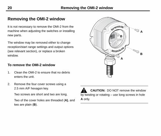
Removing the OMI-2 window
It is not necessary to remove the OMI-2 from the machine when adjusting the switches or installing new parts .
The window may be removed either to change reception/start range settings and output options (see relevant section), or replace a broken window .
To remove the OMI-2 window
1 . Clean the OMI-2 to ensure that no debris enters the unit .
2 . Remove the four cover screws using a 2 .5 mm A/F hexagon key .
Two screws are short and two are long .
Two of the cover holes are threaded (A), and two are plain (B) .
A
A
B
B
CAUTION: DO NOT remove the window by twisting or rotating – use long screws in hole A only .
!
21Removing and refitting the OMI-2 label
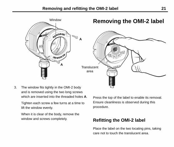
Removing the OMI-2 label
Press the top of the label to enable its removal . Ensure cleanliness is observed during this procedure .
Refitting the OMI-2 label
Place the label on the two locating pins, taking care not to touch the translucent area .
3 . The window fits tightly in the OMI-2 body and is removed using the two long screws which are inserted into the threaded holes A .
Tighten each screw a few turns at a time to lift the window evenly .
When it is clear of the body, remove the window and screws completely .
Window
A
ATranslucent
area

22 Changing the reception range
Changing the reception range
(factory set to 100% range)
To reduce the reception range to 50%, move the filter
to the position indicated
50% range
100% range
Avoid touching filter
Avoid touching filter

23Fitting the OMI-2 window
4 . Insert the two short screws into window holes A and tighten .
Screw torque is 0 .3 Nm to 0 .5 Nm (0 .22 lbf .ft to 0 .37 lbf .ft) .
5 . Place the window complete with ‘O’ ring onto the OMI-2 body .
NOTE: The ‘O’ ring should be lightly lubricated with grease .
6 . Insert the long screws into holes B . Tighten each screw a few turns at a time, to pull the window down evenly . There may be some resistance due to compression of air trapped inside the body .
Screw torque is 0 .9 Nm to 1 .1 Nm (0 .66 lbf .ft to 0 .81 lbf .ft) .
Fitting the OMI-2 window
1 . Before fitting the window, check for any damage to screws or scratch marks which could prevent sealing .
2 . Ensure that the ‘O’ ring seating in the OMI-2 body is clean .
3 . Ensure that the window and ‘O’ ring are clean .
B
A
A
B

24 Screw torque values
8 mm AF 5 Nm
(3 .68 lbf .ft)
HOLD
3 mm AF 2 Nm
(1 .47 lbf .ft)
Screw torque values
4 mm AF
7/8 in AF 22 Nm (16 .22 lbf .ft)
MAXIMUM
19 mm AF

25Fault-finding
Fault-finding
If in doubt, consult your probe supplier .
Symptom Cause Action
The probe fails to switch on when in Optical Start mode or fails to switch off when in Optical Stop mode .
Installation/CNC program fault Correct the M-code wiring and/or the CNC program .
Probe out of start range Change the CNC program to bring the probe within the start range of the OMI-2 . Ensure that the appropriate START RANGE is selected (SW2) .
Beam obstructed Clean the OMI-2 window and remove any obstructions .
Incompatible probe/probe transmission setting
Change the probe or probe setting to MODULATED .
Incorrect MACHINE START setting
Reconfigure the MACHINE START setting (SW2) .
Dead probe batteries Replace the probe batteries .
Optical interference is blocking the start signal
Remove the source of interference or reposition the OMI-2 so that interfering light does not shine onto the OMI-2 window or the probe window .
Check the visual diagnostics (see page 7) .

26 Fault-finding
Symptom Cause Action
The probe stops in mid-cycle
or
An unexpected error occurs during a probing cycle
or
An unexpected ‘trigger’ occurs during the probing cycle
Beam obstructed Remove the obstruction .
Optical interference Remove the source of interference or reposition the OMI-2 so that the interfering light does not shine into the OMI-2 window .
Intermittent wiring fault Correct the wiring .
Probe has moved outside RECEPTION RANGE
Change the CNC program to bring the probe within the RECEPTION RANGE of the OMI-2 and ensure that the appropriate RECEPTION RANGE is selected .
Probe is in Timer Off mode and has not been triggered for the timer period
Increase the Timer Off time setting or change the probing routine .
Probe has not been triggered for more than 90 minutes
Restart the probe and ensure that the probe is not idle for 90 minutes .

27Fault-finding
Symptom Cause Action
The probe switches on, but OMI-2 ERROR remains active .
Interfering light source shining directly into the OMI-2 window
Remove the source of interference or reposition the OMI-2 so that the interfering light does not shine into the OMI-2 window .
Check visual diagnostics (see page 7) .
Probe is out of range Check the SIGNAL CONDITION LED .
Change the CNC program to move the probe into the RECEPTION RANGE of the OMI-2 and ensure that the appropriate RECEPTION RANGE is selected
Probe is triggered when OMI-2 is set to Level Machine Start
Reseat the probe .
A signal is being received from a probe on an adjacent machine tool
Change the adjacent probe to Low Power Mode or change the OMI-2 RECEPTION RANGE to 50% if this range is acceptable .
Installation/CNC program fault Check the Error SSR wiring and the CNC program .

28 Fault-finding
Symptom Cause Action
The probe indicates a Low Battery condition, but the machine control does not .
Installation/CNC program fault Correct the Low Battery SSR wiring and/or the CNC program .
The machine control does not respond to the probe being triggered or seated .
Probe is not switched on Attempt to switch it on .
Probe is out of range Change the CNC program to bring the probe within the RECEPTION RANGE .
Installation/CNC program fault Correct the PROBE STATUS output(s) wiring and the CNC program .
A signal is being received from a probe on an adjacent machine tool
Change the adjacent probe to Low Power Mode or change the OMI-2 RECEPTION RANGE to 50% if this range is acceptable .
The probe fails to switch on . Probe was already on when the START signal was transmitted
Check that the probe was turned off at the end of the last probing cycle .

29Parts list
Parts list
Please quote the part number when ordering equipment .
Type Part number Description
OMI-2 kit A-5191-0049 OMI-2 with 8 m (26 ft) cable, magnetic label, tool kit and user’s guide .
OMI-2 kit A-5191-0050 OMI-2 with 15 m (49 ft) cable, magnetic label, tool kit and user’s guide .
Mounting bracket A-2033-0830 Mounting bracket .
Conduit kit A-4113-0306 Conduit kit with 1 m (3 .28 ft) of polyurethane conduit and bulkhead connector (M16 thread) .
Window replacement kit
A-5191-0019 Comprising window assembly with ‘O’ ring, 3 x stainless steel M3 x 14 mm long screws, 3 x stainless steel M3 x 5 mm long screws and 2 .5 mm hexagon wrench .
Tool kit A-5191-0300 Comprising 2 .5 mm hexagon wrench, 4 mm hexagon wrench, 14 x ferrules, 2 x M5 screws, 2 x M5 washers and 2 x M5 nuts .
The serial number of each OMI-2 is found at the bottom of the housing .


Renishaw plc
New Mills, Wotton-under-Edge, Gloucestershire, GL12 8JR United Kingdom
T +44 (0)1453 524524 F +44 (0)1453 524901 E [email protected]
www.renishaw.com
For worldwide contact details, please visit our main web site at
www.renishaw.com/contact
*H-2000-5233-03*