Numerical simulations of miscible channel flow with chemical reactions
12
RESEARCH ARTICLES CURRENT SCIENCE, VOL. 106, NO. 6, 25 MARCH 2014 841 *For correspondence. (e-mail: [email protected]) Numerical simulations of miscible channel flow with chemical reactions J. N. Kusuma 1 , Omar K. Matar 2 and Kirti Chandra Sahu 1, * 1 Department of Chemical Engineering, Indian Institute of Technology Hyderabad, Yeddumailaram 502 205, India 2 Department of Chemical Engineering, Imperial College London, South Kensington Campus, London, SW7 2AZ, UK We study the pressure-driven miscible displacement of one fluid by another in a horizontal channel in the presence of an exothermic chemical reaction. We solve the continuity, Navier–Stokes, and energy conserva- tion equations coupled to convective–discussion equa- tions of the reactant and product. The viscosity is assumed to depend on the volume fraction of the reac- tant and product as well as the temperature. The effects of relevant parameters such as the Reynolds number, Schmidt number, Damköhler number and viscosity ratio of the reactant and product are studied. Our results indicate that increasing the intensity of the chemical reaction by increasing the Damköhler num- ber and decreasing the dimensionless activation en- ergy increases the displacement rate. We have also found that increasing Reynolds number leads to more pronounced instabilities and roll-up phenomena, which in turn promote rapid displacement of the resident fluid inside the channel. Variation of the relative signifi- cance of the heat of reaction and the Schmidt numbers of the reactants and products, however, has a negligible influence on the displacement rates for the parameter ranges considered in the present work. Keywords: Chemical reaction, laminar flow, miscible flow, numerical simulation. THE dynamics of two-fluid flows is an active research area due to their central importance to a number of indus- trial applications, which include enhanced oil recovery, fixed-bed regeneration, hydrology and filtration, trans- portation of crude oil in pipelines 1 , and mixing of liquids using, for instance, static mixers 2 . In food and drink industrial plants, ‘cleaning-in-place’ processes involve the removal of a highly viscous fluid by high-speed flow of water pumped through the plant 3 . Thus in the latter case, achieving fundamental understanding of these flows permits the determination of the degree of mixing between the fluids and minimization of the amount of wastewater utilized. The stability of two-phase flows in a channel or pipe has been widely studied both theoretically 4–6 and experi- mentally 1,7–9 in the context of immiscible 9–16 and misci- ble 17– 21 fluids. By conducting a linear stability analysis, Ern et al. 19 have shown that for rapidly varying viscous stratification, diffusion can be destabilizing. However, Govindarajan 18 has demonstrated that three-layer Poiseuille flow is unstable at high Schmidt and low Reynolds numbers. In neutrally buoyant, coreannular flows, Selvam et al. 6 have shown that, above a critical viscosity ratio, the flow is unstable even when the less viscous fluid is at the wall (although it should be noted that the range of parameters over which this is true is lim- ited). This is in contrast to the studies of Joseph et al. 1 , and Malik and Hooper 22 , who found stable flow in this configuration. Several authors 23–27 have also studied miscible core-annular flows experimentally and investi- gated the thickness of the remnant fluid layer left on the pipe walls and the speed of the propagating ‘finger tip’. The development of different instability patterns, such as axisymmetric ‘corkscrew’ patterns in miscible flows, has also been studied 2,28–31 . d’Olce et al. 32 obser- ved axisymmetric ‘pearl’ and ‘mushroom’ patterns in neutrally buoyant, core-annular horizontal pipe flow at high Schmidt and Reynolds numbers in the range 2 < Re < 60. Sahu et al. 20 studied the stability of neutrally buoyant, two-fluid miscible channel flows for large viscosity con- trasts. They also carried out a generalized spatio-temporal linear stability analysis for the case of a three-layer flow 33– 35 and determined the boundaries between convec- tively and absolutely unstable flows in the space of the Reynolds number and viscosity ratio, for parameterically varying Schmidt number. The vertical gradients of viscosity perturbations were found to be the main destabilizing influence. In order to understand the flow dynamics in the nonlinear regime, the Navier–Stokes equations coupled to a convective-diffusion equation for the concentration of the more viscous fluid were solved. These transient numerical simulations demonstrated the development of complex dynamics characterized by ‘roll- up’ and convective mixing, which increase in intensity with increasing viscosity ratio, Reynolds and Schmidt numbers. Selvam et al. 36 also made a similar analysis in miscible core-annular flows at high Schmidt number. This system was also studied experimentally by d’Olce et al. 37 . They observed absolute instabilities for a range of core radii for high viscosity ratios when the less viscous fluid is in the core. The work of Sahu et al. 20 has been
Transcript of Numerical simulations of miscible channel flow with chemical reactions

RESEARCH ARTICLES
CURRENT SCIENCE, VOL. 106, NO. 6, 25 MARCH 2014 841
*For correspondence. (e-mail: [email protected])
Numerical simulations of miscible channel flow with chemical reactions J. N. Kusuma1, Omar K. Matar2 and Kirti Chandra Sahu1,* 1Department of Chemical Engineering, Indian Institute of Technology Hyderabad, Yeddumailaram 502 205, India 2Department of Chemical Engineering, Imperial College London, South Kensington Campus, London, SW7 2AZ, UK
We study the pressure-driven miscible displacement of one fluid by another in a horizontal channel in the presence of an exothermic chemical reaction. We solve the continuity, Navier–Stokes, and energy conserva-tion equations coupled to convective–discussion equa-tions of the reactant and product. The viscosity is assumed to depend on the volume fraction of the reac-tant and product as well as the temperature. The effects of relevant parameters such as the Reynolds number, Schmidt number, Damköhler number and viscosity ratio of the reactant and product are studied. Our results indicate that increasing the intensity of the chemical reaction by increasing the Damköhler num-ber and decreasing the dimensionless activation e n-ergy increases the displacement rate. We have also found that increasing Reynolds number leads to more pronounced instabilities and roll-up phenomena, which in turn promote rapid displacement of the resident fluid inside the channel. Variation of the relative signifi-cance of the heat of reaction and the Schmidt numbers of the reactants and products, however, has a negligible influence on the displacement rates for the parameter ranges considered in the present work. Keywords: Chemical reaction, laminar flow, miscible flow, numerical simulation. THE dynamics of two-fluid flows is an active research area due to their central importance to a number of indus-trial applications, which include enhanced oil recovery, fixed-bed regeneration, hydrology and filtration, trans-portation of crude oil in pipelines1, and mixing of liquids using, for instance, static mixers2. In food and drink industrial plants, ‘cleaning-in-place’ processes involve the removal of a highly viscous fluid by high-speed flow of water pumped through the plant3. Thus in the latter case, achieving fundamental understanding of these flows permits the determination of the degree of mixing between the fluids and minimization of the amount of wastewater utilized. The stability of two-phase flows in a channel or pipe has been widely studied both theoretically4–6 and experi-mentally1,7–9 in the context of immiscible9–16 and misci-ble17–21 fluids. By conducting a linear stability analysis,
Ern et al.19 have shown that for rapidly varying viscous stratification, diffusion can be destabilizing. However, Govindarajan18 has demonstrated that three-layer Poiseuille flow is unstable at high Schmidt and low Reynolds numbers. In neutrally buoyant, coreannular flows, Selvam et al.6 have shown that, above a critical viscosity ratio, the flow is unstable even when the less viscous fluid is at the wall (although it should be noted that the range of parameters over which this is true is lim-ited). This is in contrast to the studies of Joseph et al.1, and Malik and Hooper22, who found stable flow in this configuration. Several authors23–27 have also studied miscible core-annular flows experimentally and investi-gated the thickness of the remnant fluid layer left on the pipe walls and the speed of the propagating ‘finger tip’. The development of different instability patterns, such as axisymmetric ‘corkscrew’ patterns in miscible flows, has also been studied2,28–31. d’Olce et al.32 obser-ved axisymmetric ‘pearl’ and ‘mushroom’ patterns in neutrally buoyant, core-annular horizontal pipe flow at high Schmidt and Reynolds numbers in the range 2 < Re < 60. Sahu et al.20 studied the stability of neutrally buoyant, two-fluid miscible channel flows for large viscosity con-trasts. They also carried out a generalized spatio-temporal linear stability analysis for the case of a three-layer flow33–35 and determined the boundaries between convec-tively and absolutely unstable flows in the space of the Reynolds number and viscosity ratio, for parameterically varying Schmidt number. The vertical gradients of viscosity perturbations were found to be the main destabilizing influence. In order to understand the flow dynamics in the nonlinear regime, the Navier–Stokes equations coupled to a convective-diffusion equation for the concentration of the more viscous fluid were solved. These transient numerical simulations demonstrated the development of complex dynamics characterized by ‘roll-up’ and convective mixing, which increase in intensity with increasing viscosity ratio, Reynolds and Schmidt numbers. Selvam et al.36 also made a similar analysis in miscible core-annular flows at high Schmidt number. This system was also studied experimentally by d’Olce et al.37. They observed absolute instabilities for a range of core radii for high viscosity ratios when the less viscous fluid is in the core. The work of Sahu et al.20 has been

RESEARCH ARTICLES
CURRENT SCIENCE, VOL. 106, NO. 6, 25 MARCH 2014 842
extended to account for buoyancy effects in inclined channels38, and non-isothermal effects in pressure-driven miscible displacement flow5 in the nonlinear regime. The results of Sahu et al.5,38 demonstrated that the rates of mixing and displacement of the more viscous fluid are promoted by the development of Rayleigh–Taylor insta-bilities, and enhanced with increasing density ratio, Froude number and viscous heating. The mixing rates were also shown to increase with increasing inclination angles when the displaced fluid is also the denser one. In the absence of density contrast, when a highly viscous fluid displaces a less viscous one, the flow becomes unstable and the famous Saffman–Taylor instability39 occurs at the interface separating the fluids. In spite of the large volume of research on two-fluid flows, very few studies have considered the effects of chemical reactions on the flow dynamics in pressure-driven displacement flows, although their effects on vis-cous fingering in porous media have been examined extensively by several authors40–42. Nagatsu et al.43,44 have studied experimentally the reactive viscous finger-ing in a Hele-Shaw cell and found that the fingering becomes more pronounced when the product is more vis-cous than the reactant; the reverse trend was observed for reactions generating a less viscous product. For relatively slow reactions, these authors have also shown that finger-ing becomes more vigorous in the reactive than in the non-reactive case. More recently, Burghelea and Fri-gaard45 demonstrated the appearance of instability in low-Reynolds number, parallel, miscible channel flows in the presence of rapid chemical reactions. The instability characteristics depend on a number of system parameters, which include the channel aspect ratio, flow speed and viscosity contrast. In the present work, we examine the flow dynamics of miscible, pressure-driven displacements in horizontal, rectangular channels in the presence of exothermic chemical reactions, of the type A + B C, via direct nu-merical simulations. We solve the mass and energy con-servation equations coupled to convective-diffusion equations of the reactant and product, and the full Navier–Stokes equations (rather than Darcy’s equations, appropriate for Hele-Shaw flow). The viscosity is assumed to vary with temperature and the volume frac-tion of the reactant and product; the density is assumed to remain constant. The governing equations are parameter-ized by the Reynolds, Schmidt and Damköhler numbers, and the viscosity ratio of the reactant and product. Our numerical results demonstrate that increasing the inten-sity of the chemical reaction by increasing the Damköhler number and/or decreasing dimensionless activation energy increases the displacement of the resident fluid present inside the channel. We have also found that increasing the Reynolds number leads to more pronoun-ced instabilities and roll-up phenomena, which increase the displacement rates of the resident fluid.
Formulation
We consider two-dimensional miscible flow in a horizon-tal channel, wherein, initially, the channel is occupied by a stationary, viscous fluid of viscosity 1. Another liquid with viscosity 2 is injected into the channel with an average velocity V Qf/H, where Qf denotes the total flow rate; we assume the densities of all fluids to be the same. The initially resident and invading fluids are labelled ‘A’ and ‘B’, as shown in Figure 1, and their ini-tial temperatures are denoted by T1 and T2 respectively. An exothermic second-order chemical reaction of the type A + B C, accompanies the flow which takes place in the mixed region separating the two fluids; this then alters the viscosity in this region. The quantities, m and p are defined as the volume fractions of reactant A and product C; the latter is initially equal to zero. The volume fraction of reactant B is then simply equal to 1 – m – p. A rectangular coordinate system (x, y) is used to model the flow dynamics, where x and y denote the coordinates in the axial and vertical directions respectively. The channel inlet and outlet are located at x = 0 and x = L respectively. The channel walls, which are rigid and impermeable are located at y = H/2. The equations governing the problem can be written as: u = 0, (1)
[ ( )],Tpt
u u u u u (2)
2 (1 ),mm m m m m pk
t
u (3)
2 2 (1 ),pp p p m m pk
t
u (4)
2 (1 ) ,m m pT T T k qt
u (5)
where u, p and T denote the velocity, pressure and temperature fields of the fluids respectively; m and Dp are the diffusion coefficients of the reactant and product
Figure 1. Schematic diagram showing the initial flow configuration. Fluid A occupies the entire channel, and is about to be displaced by the inflowing fluid B. Symbols are defined in the text.

RESEARCH ARTICLES
CURRENT SCIENCE, VOL. 106, NO. 6, 25 MARCH 2014 843
respectively; denotes the thermal diffusivity and q is the heat of the reaction. In eqs (3)–(5), the rate of reac-tion is defined as k(T) = k0exp(–E/RT), (6) where k0 is the pre-exponential factor, E the activation energy and R is the universal gas constant. The viscosity of the fluid is assumed to depend on temperature and the volume fractions of the reactant and product as follows:
1 1(( ) / )2 1( )e ,m m p pR R T T TT
(7)
where Rm ( ln(1(T1)/2(T1))) and Rp( ln(p(T1)/2(T2))) are the log-mobility ratios of the reactant and product respectively. The following scaling is employed in order to render the governing equations dimensionless:
( , ) ( , ), , ( , ) ( , ),Hx y H x y t t u v V u vV
2 ,p V p 2 1 1 1( ), ,T T TT T (8) where the tildes designate dimensionless quantities. After dropping tildes from all non-dimensional terms, the gov-erning dimensionless equations are given by: u = 0, (9)
1 [ ( )],Tpt Re
u u u u u (10)
21mm m
mt ReSc
u
/( 1)e (1 ),T
m m pDa (11)
21pp p
pt ReSc
u
/( 1)2 e (1 ),T
m m pDa (12)
21T T Tt RePr
u
/( 1)e (1 ),T
m m pDa (13) where Re VH/2(T1) denotes the Reynolds number, Sci 2(T1)/i (i = m, p) represent the Schmidt numbers of the reactant and product; q/T1cp is the dimen-
sionless heat of reaction, and Da k0H/V and Pr cp 2(T1)/ are the Damköhler number and Prandtl num-ber respectively, wherein cp is the specific heat capacity at constant pressure. The dimensionless activation energy is given by = E/RT1, while the dimensionless tempera-ture of the invading fluid is expressed by rT = (T2 – T1)/T1. Finally, the dimensionless viscosity has the following dependence on T, m and p: = exp(Rmm + Rpp – T). (14)
Numerical methods
We use a finite-volume approach similar to the one developed by Ding et al.46 in order to solve the system of equations (9)–(14). These equations are discretized using a staggered grid; the scalar variables (pressure, tempera-ture and volume fraction) are defined at the centre of each cell and the velocity components are defined at the cell faces. The discretized advection–diffusion equations for the reactant and product, and the energy equation are given by:
1 1
2 11.5 2 0.5 1n n nnm m mm
mt ReSc
1 12 ( ) ( )n n n n
m m u u /( 1)e (1 ),T
m m pDa (15)
1 1
2 11.5 2 0.5 1n n np p p n
ppt ReSc
1 12 ( ) ( )n n n n
p p u u /( 1)e (1 ),T
m m pDa (16)
1 1
2 11.5 2 0.5 1n n nnT T T T
t RePr
1 12 ( ) ( )n n n nT T u u /( 1)e (1 ),T
m m pDa (17) where t = tn + 1 – tn and the superscript n signifies the discretized nth step. In order to discretize the advective terms in eqs (15)–(17), a weighted essentially non-oscillatory (WENO) scheme is used, while a centred-difference scheme is used to discretize the diffusive terms on the right-hand sides of these equations.
RESEARCH ARTICLES
CURRENT SCIENCE, VOL. 106, NO. 6, 25 MARCH 2014 844
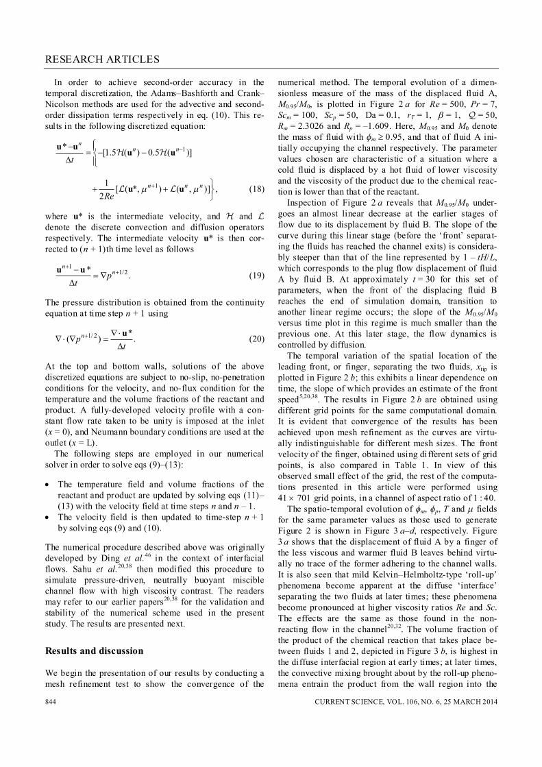
In order to achieve second-order accuracy in the temporal discretization, the Adams–Bashforth and Crank–Nicolson methods are used for the advective and second-order dissipation terms respectively in eq. (10). This re-sults in the following discretized equation:
1* [1.5 ( ) 0.5 ( )]n
n n
t
u u u u
11 [ ( *, ) ( , )] ,2
n n n
Re
u u (18)
where u* is the intermediate velocity, and and denote the discrete convection and diffusion operators respectively. The intermediate velocity u* is then cor-rected to (n + 1)th time level as follows
1
1/2* .n
npt
u u (19)
The pressure distribution is obtained from the continuity equation at time step n + 1 using
1/ 2 *( ) .npt
u (20)
At the top and bottom walls, solutions of the above discretized equations are subject to no-slip, no-penetration conditions for the velocity, and no-flux condition for the temperature and the volume fractions of the reactant and product. A fully-developed velocity profile with a con-stant flow rate taken to be unity is imposed at the inlet (x = 0), and Neumann boundary conditions are used at the outlet (x = L). The following steps are employed in our numerical solver in order to solve eqs (9)–(13): The temperature field and volume fractions of the
reactant and product are updated by solving eqs (11)–(13) with the velocity field at time steps n and n – 1.
The velocity field is then updated to time-step n + 1 by solving eqs (9) and (10).
The numerical procedure described above was originally developed by Ding et al.46 in the context of interfacial flows. Sahu et al.20,38 then modified this procedure to simulate pressure-driven, neutrally buoyant miscible channel flow with high viscosity contrast. The readers may refer to our earlier papers20,38 for the validation and stability of the numerical scheme used in the present study. The results are presented next.
Results and discussion
We begin the presentation of our results by conducting a mesh refinement test to show the convergence of the
numerical method. The temporal evolution of a dimen-sionless measure of the mass of the displaced fluid A, M0.95/M0, is plotted in Figure 2 a for Re = 500, Pr = 7, Scm = 100, Scp = 50, Da = 0.1, rT = 1, = 1, = 50, Rm = 2.3026 and Rp = –1.609. Here, M0.95 and M0 denote the mass of fluid with m 0.95, and that of fluid A ini-tially occupying the channel respectively. The parameter values chosen are characteristic of a situation where a cold fluid is displaced by a hot fluid of lower viscosity and the viscosity of the product due to the chemical reac-tion is lower than that of the reactant. Inspection of Figure 2 a reveals that M0.95/M0 under-goes an almost linear decrease at the earlier stages of flow due to its displacement by fluid B. The slope of the curve during this linear stage (before the ‘front’ separat-ing the fluids has reached the channel exits) is considera-bly steeper than that of the line represented by 1 – tH/L, which corresponds to the plug flow displacement of fluid A by fluid B. At approximately t = 30 for this set of parameters, when the front of the displacing fluid B reaches the end of simulation domain, transition to another linear regime occurs; the slope of the M0.95/M0 versus time plot in this regime is much smaller than the previous one. At this later stage, the flow dynamics is controlled by diffusion. The temporal variation of the spatial location of the leading front, or finger, separating the two fluids, xtip is plotted in Figure 2 b; this exhibits a linear dependence on time, the slope of which provides an estimate of the front speed5,20,38. The results in Figure 2 b are obtained using different grid points for the same computational domain. It is evident that convergence of the results has been achieved upon mesh refinement as the curves are virtu-ally indistinguishable for different mesh sizes. The front velocity of the finger, obtained using different sets of grid points, is also compared in Table 1. In view of this observed small effect of the grid, the rest of the computa-tions presented in this article were performed using 41 701 grid points, in a channel of aspect ratio of 1 : 40. The spatio-temporal evolution of m, p, T and fields for the same parameter values as those used to generate Figure 2 is shown in Figure 3 a–d, respectively. Figure 3 a shows that the displacement of fluid A by a finger of the less viscous and warmer fluid B leaves behind virtu-ally no trace of the former adhering to the channel walls. It is also seen that mild Kelvin–Helmholtz-type ‘roll-up’ phenomena become apparent at the diffuse ‘interface’ separating the two fluids at later times; these phenomena become pronounced at higher viscosity ratios Re and Sc. The effects are the same as those found in the non-reacting flow in the channel20,32. The volume fraction of the product of the chemical reaction that takes place be-tween fluids 1 and 2, depicted in Figure 3 b, is highest in the diffuse interfacial region at early times; at later times, the convective mixing brought about by the roll-up pheno-mena entrain the product from the wall region into the

RESEARCH ARTICLES
CURRENT SCIENCE, VOL. 106, NO. 6, 25 MARCH 2014 845
Figure 2. a, Mass fraction M0.95 = M0 of m and b, temporal evolut ion of the posit ion of the leading front separating the two fluids, x tip for different grid densit ies. The rest of the parameter values are Re = 500, Pr = 7, Scm = 100, Scp = 50, Da = 0.1, rT = 1, = 1, = 50, Rm = 2.3026 and Rp = –1.609. Dotted lines in panel (a) and (b) represent the limit ing case given by M0.95/M0 = 1 – tH/L and x tip = t respectively.
Figure 3. Spatio- temporal evolution of the contours of (a) m, (b) p, (c) T and (d) at successive times (from top to bottom: t = 10, 20 and 25). The rest of the parameter values are the same as those used to generate Figure 2. The colour maps are shown at the bottom.
Table 1. Velocity of the fingertip, Vf, for different grid densities. The rest of the parameter values are the same as those used to generate Figure 2.
Grid Vf
41 701 1.584 61 701 1.587 41 1001 1.56
core. The mixing action of the roll-up instabilities is also clearly seen in the case of the temperature within the channel shown in Figure 3 c. In contrast, very little mix-ing can be seen in the case of the viscosity , which exhibits similar patterns to those associated with the dynamics of fluids 1 and 2, as shown in Figure 3 d; this is
due to the dependence of on m through the term exp(Rm m) in eq. (14) which for the parameter values used to generate Figure 3, is the dominant contribution to that equation. To compare this dynamics to a reference case, the spatio-temporal evolution of m, p, T and fields for rT = 0, with the rest of the parameter values remaining the same as in Figure 2, is shown in Figure 4 a–d, respectively. In this case, there is no imposed tem-perature gradient, i.e. the system is isothermal at t = 0. However, at later times, a temperature gradient arises due to heat generation by the exothermic chemical reaction. It can be clearly seen in Figure 4 c that the temperature is maximum at the interfacial region where the reaction takes place. Next, we examine the parametric dependence of the temporal variation of M0.95/M0 on Da, which provides a

RESEARCH ARTICLES
CURRENT SCIENCE, VOL. 106, NO. 6, 25 MARCH 2014 846
Figure 4. Spatio- temporal evolution of the contours of (a) m, (b) p, (c) T and (d) at successive times (from top to bottom: t = 10, 20 and 25) for rT = 0 (at t = 0 flow is isothermal). The rest of the parameter values are the same as those used to generate Figure 2. The colour maps are shown at the bottom.
Figure 5. (a, c), Mass fraction M0.95/M0 of m, and (b, d), temporal evolut ion of the position of the leading front separat-ing the two fluids, x tip for different values of Da. (a, b) and (c, d), correspond to the parameters (Rm = 2.3026 and Rp = –1.609) and (Rm = 1.609 and Rp = 2.3026) respectively. The rest of the parameter values are Re = 500, Pr = 7, Scm = 100, Scp = 50, rT = 1, = 1 and = 50. Dotted lines in (a, c) and (b, d) represent the limit ing case given by M0.95/M0 = 1 – tH/L and x tip = t respectively.
dimensionless measure of the relative importance of chemical reactions in this flow. This is shown in Figure 5 with the rest of the parameters remaining unaltered from those used to generate Figures 2 and 3. Figure 5 a shows
that increasing the relative intensity of chemical reaction by increasing Da leads to more rapid displacement in comparison to displacement without chemical reactions (Da = 0). It can be seen that all the curves in Figure 5 a

RESEARCH ARTICLES
CURRENT SCIENCE, VOL. 106, NO. 6, 25 MARCH 2014 847
lie below the 1 – tH/L curve that corresponds to a plug-flow-type displacement in which the ‘interface’ separat-ing the fluids remains vertical throughout; the curves closest to the 1 – tH/L line are those associated with Da = 0. In Figure 5 b, it is clearly seen that increasing Da leads to an increase in the speed of the penetrating front.
Figure 6. Spatio-temporal evolution of the contours of m for (a) Da = 0 and (b) Da = 0.5 at successive times (from top to bottom in each panel: t = 5, 10, 15 and 20) for Rm = 2.3026 and Rp = – 1.609. The rest of the parameter values are the same as those used to generate Figure 5. Colour map is shown at the bottom.
Figure 7. Spatio- temporal evolut ion of the contours of for (a) Da = 0 and (b) Da = 0.5 at successive times (from top to bottom in each panel: t = 5, 10, 15 and 20) for Rm = 2.3026 and Rp = – 1.609. The rest of the parameter values are the same as those used to generate Figure 5. Colour map is shown at the bottom.
The spatio-temporal evolution of the m fields associ-ated with Da = 0 and 0.5 is shown in Figure 6 a and b respectively. It can be seen in Figure 6 a that for Da = 0, the remnants of m assume the form of thin layers
Figure 8. Spatio-temporal evolution of the contours of m for (a) Da = 0 and (b) Da = 0.5 at successive times (from top to bottom in each panel: t = 5, 10, 15 and 20) for Rm = 1.609 and Rp = 2.3026. The rest of the parameter values are the same as those used to generate Figure 5. Colour map is shown at the bottom.
Figure 9. Spatio- temporal evolut ion of the contours of for (a) Da = 0 and (b) Da = 0.5 at successive times (from top to bottom in each panel: t = 5, 10, 15 and 20) for Rm = 1.609 and Rp = 2.3026. The rest of the parameter values are the same as those used to generate Figure 5. Colour map is shown at the bottom.

RESEARCH ARTICLES
CURRENT SCIENCE, VOL. 106, NO. 6, 25 MARCH 2014 848
Figure 10. a, Mass fraction M0.95/M0 of m, and b, temporal evolution of the position of the leading front separating the two fluids, x tip for different values of the dimensionless activation energy . The rest of the parameter values are Re = 500, Pr = 7, Scm = 100, Scp = 50, rT = 1, Da = 0.1, = 50, Rm = 2.3026 and Rp = – 1.609. Dotted lines in panel (a) and (b) represent the limit ing case given by M0.95/M0 = 1 – tH/L and x tip = t, respectively.
Figure 11. Spatio- temporal evolut ion of the contours of m for differ-ent values of the dimensionless activation energy, : (a) = 0.5 and (b) = 10 at successive times (from top to bottom in each panel: t = 5, 10, 15 and 20). The rest of the parameter values are the same as those used to generate Figure 10. Colour map is shown at the bottom.
adjacent to the upper and lower channel walls. Also evi-dent are roll-up instabilities that lead to vigorous, convec-tive mixing of the two fluids. In the reactive flow case (Da = 0.5), shown in Figure 6 b, the flow dynamics is rather less complex: the ‘interfacial’ region remains more parabolic than in the nonreactive case, with a well-defined ‘nose’ and less evidence of instability. It can also be seen that reactive displacements appear to be faster and more efficient than non-reactive ones, with very little fluid A left at the walls. This is because the viscosity of the wall layers is significantly lower in the case of reac-tive displacements (see Figure 7), which facilitates their
removal. Thus the displacement rate increases with in-creasing Da (shown in Figure 5 a). Interestingly, we have found that even for Rp > 0, i.e. when 2 < p < 1, the chemical reaction helps in the cleaning process by increasing the displacement rate as shown in Figure 5 c, generated for Rm = 1.609 and Rp = 2.3026, with the rest of the parameter values remain-ing unaltered from Figure 5 a. Close inspection of the m field in Figure 8 b, however, shows that the parabolic nose shape, characteristic of the interfacial region in the Rp < 0 case (shown in Figure 6 b), has given way to a sharper structure whose tip becomes increasingly elon-gated with time. In case of miscible flow without chemical reaction, this type of finger of the invading fluid with sharp nose was observed experimentally by Petitjeans and Maxworthy25, and numerically by Rakotomalala et al.47. The viscosity fields for Da = 0 and Da = 0.5 with the rest of the parameter values same as Figure 5 c and d are shown in Figure 9 a and b respectively. In this case, it can be seen that the viscosity of the fluid in front of the invading finger becomes significantly lower compared to that of the fluid initially present in this region, which accelerates the displacement process. The effect of varying the dimensionless activation energy , on the displacement process is shown in Figure 10. The temporal evolution of the dimensionless mass of the displaced fluid A, M0.95/M0, and the position of the leading front separating the two fluids, xt ip, are plotted for different values of in Figure 10 a and b, respectively; the rest of the parameters remain unaltered from Figure 2. As expected, increasing the values of , which raises the activation energy barrier for the chemical reaction, decreases the displacement rate (see Figure 10 a). Figure 10 b reveals that the velocity of the leading front also de-creases with increasing . The spatio-temporal evolution of the m fields associated with = 0.5 and 10 is shown in Figure 11 a and b respectively. As expected, it can be seen that the flow dynamics associated with higher

RESEARCH ARTICLES
CURRENT SCIENCE, VOL. 106, NO. 6, 25 MARCH 2014 849
Figure 12. a, Mass fraction M0.95/M0 of m and b, temporal evolut ion of the position of the leading front separating the two fluids, x tip for different values of the dimensionless temperature of the invading fluid, rT. The rest of the parameter values are Re = 500, Pr = 7, Scm = 100, Scp = 50, Da = 0.05, = 5, = 50, Rm = 2.3026 and Rp = – 1.609. Dotted lines in a and b represent the limiting case given by M0. 95/M0 = 1 – tH/L and x tip = t, respective ly.
Figure 13. Spatio-temporal evolut ion of m for different values of the dimensionless tempera-ture of the invading fluid, rT : a, rT = 0 and b, rT = 5 at successive times (from top to bottom in each panel: t = 5, 10, 15 and 20). The rest of the parameter values are the same as those used to generate Figure 12. Colour map is shown at the bottom.
value is qualitatively similar to that associated with the smaller Da value considered. Next, in Figure 12 we study the effect of rT with Da = 0.05, = 200 and = 5, the dimensionless tempe-rature of the invading fluid (fluid B) on the displacement characteristics. The rest of the parameter values remain unaltered from Figure 2. It can be seen in Figure 12 a that increasing rT progressively from 0 to 5 leads to more rapid displacement of fluid A in comparison to the iso-thermal case. In Figure 12 b, it can be seen that the posi-tion of the leading front separating the two fluids, xt ip, is weakly dependent on variation in rT values. It can also be seen that all the curves in Figure 12 a lie below
1 – tH/L (and these in Figure 12 b are above xt ip = t), which corresponds to plug flow displacements. This is due to the presence of instabilities which enhance mixing and increase the displacement rate. The above results are rationalized by examining the spatio-temporal evolution of m contours for rT = 0 and rT = 5 in Figure 13 a and b respectively. The rest of the parameter values remain unchanged from those used to generate Figure 12. rT = 5 corresponds to the case when a warmer fluid displaces a cooler one. For rT = 0 (isother-mal flow at t = 0), it can be seen that fluid A is penetrated by a relatively stable finger of fluid B at the early times (t < 10). Similar observations were made by Sahu et al.5,

RESEARCH ARTICLES
CURRENT SCIENCE, VOL. 106, NO. 6, 25 MARCH 2014 850
Figure 14. a, Mass fraction M0.95/M0 of m, and b, temporal evolut ion of the position of the leading front separating the two fluids, x tip for different values of Re. c, Spatio-temporal evolut ion of m at t = 20 for different Reynolds numbers (from top to bottom in each panel: Re = 50, 100, 500 and 1000). The rest of the parameter values are Pr = 7, Scm = 100, Scp = 50, rT = 1, Da = 0.1, = 5, = 50, Rm = 2.3026 and Rp = –1.609. Dotted lines in (a) and (b) represent the limit ing case given by M0.95/M0 = 1 – tH/L and x tip = t respectively.
Figure 15. (a, c) Mass fraction M0.95/M0 of m, and (b, d) temporal evolut ion of the position of the leading front separat-ing the two fluids, x tip. (a, b) and (c, d) are plotted for different values of Scm for Scp = 50, and Scp for Scm = 100 respec-tively. The rest of the parameter values are Re = 500, Pr = 7, rT = 1, Da = 0.1, = 1, = 50, Rm = 2.3026 and Rp = – 1.609. Dotted lines in (a) and (b) represent the limiting case given by M0. 95/M0 = 1 – tH/L and x tip = t respectively.

RESEARCH ARTICLES
CURRENT SCIENCE, VOL. 106, NO. 6, 25 MARCH 2014 851
Figure 16. a, Mass fraction M0.95/M0 of m, and b, temporal evolut ion of the position of the leading front separating the two fluids, x tip for different values of . The rest of the parameter values are Re = 500, Pr = 7, Scm = 100, Scp = 50, rT = 1, Da = 0.1, = 1, Rm = 2.3026 and Rp = – 1.609. Dotted lines in (a) and (b) represent the limit ing case given by M0.95/M0 = 1 – tH/L and x tip = t respectively.
who studied the displacement flow without chemical reaction. In contrast to the rT = 0 case, for rT = 5, the flow appears to be considerably more unstable due to the asso-ciated increase in viscosity contrasts. As a result, the region separating fluids 1 and 2 is highly diffuse and hence a higher displacement rate is observed for rT = 5 compared to rT = 0. Finally, we have studied the effect of varying Re on the flow dynamics. As shown in Figure 14, increasing Re leads to more pronounced roll-up phenomena, highly convective mixing and rapid displacement rates. Varia-tion of Scm, Scp and was also found to have a negligible effect on the displacement rates, as shown in Figures 15 and 16.
Conclusion
Pressure-driven displacement of one fluid by another in a horizontal channel in the presence of an exothermic chemical reaction is studied numerically. In our simula-tions, the continuity, Navier–Stokes and energy equations coupled to two convective-diffusion equations of the reactant and product, are solved using a finite-volume approach. The viscosity is assumed to be an exponential function of the temperature as well as the volume fraction of the reactant and product. In order to isolate the effects of viscosity contrast, the density is assumed to be con-stant. The effects of relevant parameters such as the Reynolds number, Schmidt number, Damköhler number and viscosity ratio of the reactant and product are investi-gated. The results of the present study indicate that increasing the intensity of the chemical reaction by increasing Dam-köhler number and decreasing dimensionless activation energy increases the displacement rate. For situations characterized by a product viscosity that is lower than that of the reactants, the viscosity of the fluid layers adja-cent to the wall is lower in the presence of chemical reac-
tions than in the unreactive case, which facilitates their removal. For cases wherein the product viscosity is in-termediate between that of the reactants, it is the fact that the chemical reaction reduces the viscosity of the resident fluid ahead of the displacing fluid that promotes its dis-placement. More pronounced instabilities and roll-up phenomena are observed with increasing Reynolds num-ber, which increases the displacement rate of the resident fluid inside the channel. For the parameter range consid-ered, we found that the heat of reaction and the Schmidt numbers of the reactant and product have a negligible in-fluence on the displacement characteristics. The present simulations are two-dimensional and it will be interesting to study the effects of chemical reaction in a three-dimensional channel. However, intuitively we can expect a more profound effect of chemical reaction in that case. It will also be interesting to conduct experiments in such flow systems.
1. Joseph, D. D., Bai, R., Chen, K. P. and Renardy, Y. Y., Core-annular flows. Annu. Rev. Fluid Mech., 1997, 29, 65–90.
2. Cao, Q., Ventresca, L., Sreenivas, K. R. and Prasad, A. K., Insta-bility due to viscosity stratification downstream of a centreline injector. Can. J. Chem. Eng., 2003, 81, 913–922.
3. Regner, M., Henningsson, M., Wiklund, J., Östergren, K. and Trägårdh, C., Predicting the displacement of yoghurt by water in a pipe using CFD. Chem. Eng. Technol., 2007, 30, 844–853.
4. Fernandez, J., Kurowski, P., Petitjeans, P. and Meiburg, E., Den-sity driven unstable flows of miscible fluids in a Hele-Shaw cell,’ J. Fluid Mech., 2002, 451, 239–260.
5. Sahu, K. C., Ding, H. and Matar, O. K., Numerical simulation of nonisothermal pressure-driven miscible channel flow with viscous heating. Chem. Eng. Sci., 2010, 65, 3260–3267.
6. Selvam, B., Merk, S., Govindarajan, R. and Meiburg, E., Stability of miscible core-annular flows with viscosity stratification. J. Fluid Mech., 2007, 592, 23–49.
7. Hu, H. H. and Joseph, D. D., Lubricated pipelining: stability of core-annular flows. Part 2. J. Fluid Mech., 1989, 205, 395–396.
8. Joseph, D. D. and Renardy, Y. Y., Fundamentals of two-fluid dynamics. Part II: Lubricated Transport, Drops and Miscible Liquids, Springer-Verlag, New York, 1992.

RESEARCH ARTICLES
CURRENT SCIENCE, VOL. 106, NO. 6, 25 MARCH 2014 852
9. Hickox, C. E., Instability due to viscosity and density stratification in axisymmetric pipe flow. Phys. Fluids, 1971, 14, 251–262.
10. Yih, C. S., Instability due to viscous stratification. J. Fluid Mech., 1967, 27, 337–352.
11. Joseph, D. D., Renardy, M. and Renardy, Y. Y., Instability of the flow of two immiscible liquids with different viscosit ies in a pipe. J. Fluid Mech., 1984, 141, 309–317.
12. Kouris, C. and Tsamopoulos, J., Dynamics of axisymmetric core-annular flow in a straight tube. I. The more viscous fluid in the core, bamboo waves. Phys. Fluids, 2001, 13, 841–858.
13. Kouris, C. and Tsamopoulos, J., Dynamics of axisymmetric core-annular flow in a straight tube. II. The less viscous fluid in the core, saw tooth waves. Phys. Fluids, 2002, 14, 1011–1029.
14. Sahu, K. C. and Matar, O. K., Three-dimensional convective and absolute instabilities in pressure-driven two-layer channel flow. Int. J. Multiphase Flow, 2011, 37, 987–993.
15. Sahu, K. C. and Matar, O. K., Three-dimensional linear instability in pressure-driven two-layer channel flow of a Newtonian and a Herschel–Bulkley fluid. Phys. Fluids, 2010, 22, 112-103.
16. Sahu, K. C., Valluri, P., Spelt, P. D. M. and Matar, O. K., Linear instability of pressure-driven channel flow of a Newtonian and Herschel–Bulkley fluid. Phys. Fluids, 2007, 19, 122101.
17. Ranganathan, B. T. and Govindarajan, R., Stabilisation and desta-bilization of channel flow by location of viscosity-stratified fluid layer. Phys. Fluids, 2001, 13(1), 1–3.
18. Govindarajan, R., Effect of miscibility on the linear instability of two-fluid channel flow. Int. J. Multiphase Flow, 2004, 30, 1177–1192.
19. Ern, P., Charru, F. and Luchini, P., Stability analysis of a shear flow with strongly stratified viscosity. J. Fluid Mech., 2003, 496, 295–312.
20. Sahu, K. C., Ding, H., Valluri, P. and Matar, O. K., Linear stabil-ity analys is and numerical simulation of miscible channel flows. Phys. Fluids, 2009, 21, 042104.
21. Sahu, K. C. and Govindarajan, R., Linear stability of double-diffusive two-fluid channel flow. J. Fluid Mech., 2011, 687, 529–539.
22. Malik, S. V. and Hooper, A. P., Linear stability and energy growth of viscosity stratified flows. Phys. Fluids, 2005, 17, 024101.
23. Taylor, G. I., Deposit ion of viscous fluid on the wall of a tube. J. Fluid Mech., 1961, 10, 161–165.
24. Cox, B. G., On driving a viscous fluid out of a tube. J. Fluid Mech., 1962, 14, 81–96.
25. Petitjeans, P. and Maxworthy, P., Miscible displacements in capillary tubes. Part 1. Experiments. J. Fluid Mech., 1996, 326, 37–56.
26. Chen, C.-Y. and Meiburg, E., Miscible displacement in capillary tubes. Part 2. Numerical simulations. J. Fluid Mech., 1996, 326, 57–90.
27. Kuang, J., Maxworthy, T. and Petitjeans, P., Miscible displace-ments between silicone oils in capillary tubes. Eur. J. Mech., 2003, 22, 271–277.
28. Lajeunesse, E., Martin, J., Rakotomalala, N. and Salin, D., 3D instability of miscible displacements in a Hele-Shaw cell. Phys. Rev. Lett., 1997, 79, 5254–5257.
29. Lajeunesse, E., Martin, J., Rakotomalala, N., Salin, D. and Yort-sos, Y. C., Miscible displacement in a Hele-Shaw cell at high rates. J. Fluid Mech., 1999, 398, 299–319.
30. Scoffoni, J., Lajeunesse, E. and Homsy, G. M., Interface instabili-ties during displacement of two miscible fluids in a vertical pipe. Phys. Fluids, 2001, 13, 553–556.
31. Gabard, C. and Hulin, J.-P., Miscible displacement of non-Newtonian fluids in a vertical tube. Eur. Phys. J. E, 2003, 11, 231–241.
32. d’Olce, M., Martin, J., Rakotomalala, N., Salin, D. and Talon, L., Pearl and mushroom instability patterns in two miscible fluids core annular flows. Phys. Fluids, 2008, 20, 024104.
33. Huerre, P. and Monkewitz, P. A., Local and global instability in spatially developing flows. Annu. Rev. Fluid Mech., 1990, 22, 473–537.
34. Chomaz, J.-M., Global instabilit ies in spatially developing flows: nonnormality and nonlinearity. Annu. Rev. Fluid Mech., 2005, 37, 357–392.
35. Schmid, P. J. and Henningson, D. S., Stability and Transit ion in Shear Flows, Springer, New York, 2001.
36. Selvam, B., Talon, L., Lesshafft, L. and Meiburg, E., Convec-tive/absolute instability in miscible core-annular flow. Part 2. Numerical simulations and nonlinear global modes. J. Fluid Mech., 2009, 618, 323–348.
37. d’Olce, M., Martin, J., Rakotonalala, N., Salin, D. and Talon, L., Convective/absolute instability in miscible core-annular flow. Part 1: Experiments. J. Fluid Mech., 2009, 618, 305–322.
38. Sahu, K. C., Ding, H., Valluri, P. and Matar, O. K., Pressure-driven miscible two-fluid channel flow with density gradients. Phys. Fluids, 2009, 21, 043603.
39. Saffman, P. G. and Taylor, G. I., The penetration of a fluid into a porous medium or Hele-Shaw cell containing a more viscous liquid. Proc. R. Soc. London, Ser. A, 1958, 245, 312–329.
40. De Wit, A. and Homsy, G. M., Nonlinear interactions of chemical reactions and viscous fingering in porous media. Phys. Fluids, 1999, 11(5), 949–951.
41. Kalliadasis, S., Yang, J. and De Wit, A., Fingering instabilit ies of exothermic reaction-diffus ion fronts in porous media. Phys. Fluids, 2004, 16(5), 1395–1409.
42. Bratsun, D. A. and De Wit, A., Buoyancy-driven pattern formation in reactive immiscible two-layer systems. Chem. Eng. Sci., 2011, 66, 5723–5734.
43. Nagatsu, Y., Matsuda, K., Kato, Y. and Tada, Y., Experimental study on miscible viscous fingering involving viscosity changes induced by variations in chemical species concentrations due to chemical reactions. J. Fluid Mech., 2007, 571, 475–493.
44. Nagatsu, Y., Kondo, Y., Kato, Y. and Tada, Y., Effects of moder-ate Damkohler number on miscible viscous fingering involving viscosity decrease due to a chemical reaction. J. Fluid Mech., 2009, 625, 97–124.
45. Burghelea, T. I. and Frigaard, I. A., Unstable parallel flows trig-gered by a fast chemical reaction. J. Non-Newton. Fluid Mech., 2011, 166, 500–514.
46. Ding, H., Spelt, P. D. M. and Shu, C., Diffuse interface model for incompressible two-phase flows with large density ratios. J. Com-put. Phys., 2007, 226, 2078–2095.
47. Rakotomalala, N., Salin, D. and Watzky, P., Miscible displace-ment between two parallel plates: BGK lattice gas simulations. J. Fluid Mech., 1997, 338, 277–297.
Received 19 August 2013; revised accepted 30 January 2014