Numerical investigation of performance characteristics of a cyclone prolonged with a dipleg
7
Chemical Engineering Journal 151 (2009) 39–45 Contents lists available at ScienceDirect Chemical Engineering Journal journal homepage: www.elsevier.com/locate/cej Numerical investigation of performance characteristics of a cyclone prolonged with a dipleg Fuat Kaya ∗ , Irfan Karagoz 1 Uludag University, Department of Mechanical Engineering, 16059 Bursa, Turkey article info Article history: Received 23 May 2008 Received in revised form 19 January 2009 Accepted 26 January 2009 Keywords: Swirling flows Separation efficiency Numerical simulation Lagrangian method abstract Numerical modeling of a particle separation process is carried out to understand the gas-particle two- phase flow field inside a cyclone prolonged with a dipleg and results of the numerical simulations are compared with experimental data to validate the numerical results. The flow inside the cyclone separator is modeled as a three-dimensional turbulent continuous gas flow with solid particles as a discrete phase. The continuous gas flow is predicted by solving Navier–Stokes equations using the differential RSM tur- bulence model with nonequilibrium wall functions. The second phase is modeled based on a Lagrangian approach. Analysis of computed results shows that the length of the dipleg considerably influences the cyclone separation efficiency rather than the cyclone pressure drop, especially for lower inlet velocities in relatively short cyclones, by providing more separation space. © 2009 Elsevier B.V. All rights reserved. 1. Introduction An efficient removal of particles from two-phase flows is essential to develop advanced separation technologies. Cyclone separators are widely used for this purpose, due to their sev- eral advantages such as simple design, absence of moving parts, low manufacturing and maintenance costs. Entrance of flow into cyclone can be axial or tangential through inlet section, which can be in different shapes for each cyclone. Cyclone separators oper- ate under the action of centrifugal forces. Fluid mixture enters the cyclone and makes a swirl motion and, due to the centrifugal forces, the particles in the flow gain a relative motion in the radial direc- tion and are separated from the main flow. It is difficult to analyze this problem, since this swirling flow is very complex, and there are many parameters influenced this flow. The main performance char- acteristics of a cyclone separator are collection efficiency, fractional efficiencies and pressure losses. Many experimental and theoretical studies performed on this difficult problem provide semiempirical models ranging from simple [1–4] to more comprehensive models [5,6] for the prediction of a cyclone performance. Due to the fact that the fluids dynamics of cyclones are com- plex, including highly turbulent structure and limitations in the usage of empirical models, optimization of cyclone performance by improving the cyclone efficiency and minimizing the pressure drop was essentially based on experiments rather than theoretical studies [7–14]. However, the computational fluid dynamics (CFD) ∗ Corresponding author. Tel.: +90 224 2941997; fax: +90 224 2941903. E-mail address: [email protected] (F. Kaya). 1 Tel.: +90 224 2941911; fax: +90 224 2941903. of cyclones has exploded recently with advances in computer capa- bilities, numerical methods and software, and with the advent to the field of a large number of investigators [15–23]. Although many works have been carried out to investigate the influence of different geometric parameters such as cyclone length, inlet and outlet pipe geometries etc. on the performance of cyclones, there has been little work concerning the dust outlet geometries. Obermair et al. [24] performed cyclone tests with five different dust outlet geometries to find the influence of the dust outlet geometry on the separation process. They showed that sepa- ration efficiency can be improved significantly by changing the dust outlet geometry, and they reported that further research is needed to clarify precise effects of dust outlet geometry. The effect of a dipleg was posed and investigated by several researchers [25–27]. It is well known that in a reverse flow cyclone, the outer vortex flow weakens and changes its direction at a certain axial distance from the vortex finder. This axial magnitude has been called the “natural length” or the “vortex length” of the cyclone, and the axial position is referred to as “the end of the vortex”. The influence of the dipleg on the vortex and flow characteristics was investigated by Gil et al. [27], and they found that the vortex end was related not only to inlet and vortex finder geometry, but also to inlet gas velocity and solid loading. They also found that a small amount of “underflow” drawn through the dust exit causes the vortex end to move down the dipleg and a higher dust loading caused the end of the vortex to move up the dipleg. Hoffmann et al. [28] studied the effect of cyclone length on separation efficiency and pressure drop, experimentally and the- oretically, by varying the length of the cylindrical segment of a cylinder-on-cone cyclone. They showed that the separation effi- ciency improves for certain ratio of L/D. However, they found an 1385-8947/$ – see front matter © 2009 Elsevier B.V. All rights reserved. doi:10.1016/j.cej.2009.01.040
-
Upload
independent -
Category
Documents
-
view
5 -
download
0
Transcript of Numerical investigation of performance characteristics of a cyclone prolonged with a dipleg
Nw
FU
a
ARRA
KSSNL
1
eselcbactttmaesm[
pubds
1d
Chemical Engineering Journal 151 (2009) 39–45
Contents lists available at ScienceDirect
Chemical Engineering Journal
journa l homepage: www.e lsev ier .com/ locate /ce j
umerical investigation of performance characteristics of a cyclone prolongedith a dipleg
uat Kaya ∗, Irfan Karagoz1
ludag University, Department of Mechanical Engineering, 16059 Bursa, Turkey
r t i c l e i n f o
rticle history:eceived 23 May 2008eceived in revised form 19 January 2009
a b s t r a c t
Numerical modeling of a particle separation process is carried out to understand the gas-particle two-phase flow field inside a cyclone prolonged with a dipleg and results of the numerical simulations are
ccepted 26 January 2009
eywords:wirling flowseparation efficiency
compared with experimental data to validate the numerical results. The flow inside the cyclone separatoris modeled as a three-dimensional turbulent continuous gas flow with solid particles as a discrete phase.The continuous gas flow is predicted by solving Navier–Stokes equations using the differential RSM tur-bulence model with nonequilibrium wall functions. The second phase is modeled based on a Lagrangianapproach. Analysis of computed results shows that the length of the dipleg considerably influences the
ncy rs, by
umerical simulationagrangian method
cyclone separation efficiein relatively short cyclone
. Introduction
An efficient removal of particles from two-phase flows isssential to develop advanced separation technologies. Cycloneeparators are widely used for this purpose, due to their sev-ral advantages such as simple design, absence of moving parts,ow manufacturing and maintenance costs. Entrance of flow intoyclone can be axial or tangential through inlet section, which cane in different shapes for each cyclone. Cyclone separators oper-te under the action of centrifugal forces. Fluid mixture enters theyclone and makes a swirl motion and, due to the centrifugal forces,he particles in the flow gain a relative motion in the radial direc-ion and are separated from the main flow. It is difficult to analyzehis problem, since this swirling flow is very complex, and there are
any parameters influenced this flow. The main performance char-cteristics of a cyclone separator are collection efficiency, fractionalfficiencies and pressure losses. Many experimental and theoreticaltudies performed on this difficult problem provide semiempiricalodels ranging from simple [1–4] to more comprehensive models
5,6] for the prediction of a cyclone performance.Due to the fact that the fluids dynamics of cyclones are com-
lex, including highly turbulent structure and limitations in the
sage of empirical models, optimization of cyclone performancey improving the cyclone efficiency and minimizing the pressurerop was essentially based on experiments rather than theoreticaltudies [7–14]. However, the computational fluid dynamics (CFD)∗ Corresponding author. Tel.: +90 224 2941997; fax: +90 224 2941903.E-mail address: [email protected] (F. Kaya).
1 Tel.: +90 224 2941911; fax: +90 224 2941903.
385-8947/$ – see front matter © 2009 Elsevier B.V. All rights reserved.oi:10.1016/j.cej.2009.01.040
ather than the cyclone pressure drop, especially for lower inlet velocitiesproviding more separation space.
© 2009 Elsevier B.V. All rights reserved.
of cyclones has exploded recently with advances in computer capa-bilities, numerical methods and software, and with the advent tothe field of a large number of investigators [15–23].
Although many works have been carried out to investigatethe influence of different geometric parameters such as cyclonelength, inlet and outlet pipe geometries etc. on the performanceof cyclones, there has been little work concerning the dust outletgeometries. Obermair et al. [24] performed cyclone tests with fivedifferent dust outlet geometries to find the influence of the dustoutlet geometry on the separation process. They showed that sepa-ration efficiency can be improved significantly by changing the dustoutlet geometry, and they reported that further research is neededto clarify precise effects of dust outlet geometry. The effect of adipleg was posed and investigated by several researchers [25–27].
It is well known that in a reverse flow cyclone, the outer vortexflow weakens and changes its direction at a certain axial distancefrom the vortex finder. This axial magnitude has been called the“natural length” or the “vortex length” of the cyclone, and the axialposition is referred to as “the end of the vortex”. The influence ofthe dipleg on the vortex and flow characteristics was investigatedby Gil et al. [27], and they found that the vortex end was relatednot only to inlet and vortex finder geometry, but also to inlet gasvelocity and solid loading. They also found that a small amount of“underflow” drawn through the dust exit causes the vortex end tomove down the dipleg and a higher dust loading caused the end ofthe vortex to move up the dipleg.
Hoffmann et al. [28] studied the effect of cyclone length onseparation efficiency and pressure drop, experimentally and the-oretically, by varying the length of the cylindrical segment of acylinder-on-cone cyclone. They showed that the separation effi-ciency improves for certain ratio of L/D. However, they found an
4 nginee
oL
cietdwra
tutra(a
2
2
csit
m
0 F. Kaya, I. Karagoz / Chemical E
ptimal cyclone length: lengthening the cyclone to more than/D = 5.65 dramatically lower separation efficiency.
Qian et al. [29] studied, experimentally and numerically, ayclone prolonged with a dipleg. They stated that the dipleg hasmportant influence on separation efficiency of the cyclones. How-ver, their work is very specific and has not exhaustively exploredhe effects of the dipleg. They studied only one cyclone with threeifferent dipleg lengths. Their experimental and numerical testsere carried out for a single inlet velocity and a particle diameter,
espectively. Therefore, the question can be considered still opennd needs further investigation.
The aim of the present study is to give a detailed description ofhe flow structure in a tangential inlet cyclone with a dipleg locatednder the cyclone and to investigate the effects of the dipleg onhe cyclone collection efficiency and pressure drop. Computationalesults were verified by comparing them with experimental datavailable in the literature. The differential Reynolds Stress ModelRSM) was employed for turbulence closure and the Lagrangianpproach was used to compute discrete particle motions.
. Theoretical bases
.1. Modeling of airflow and turbulence
Cyclone separator consists of three main parts: inlet, separationhamber and vortex finder. Tangential inlets are preferred for theeparation of particles from gases [30]. Therefore, the present works deal with a tangential inlet cyclone whose schematic represen-ation is given in Fig. 1.
The Reynolds-averaged equations for conservation of mass and
omentum can be written in the following compact form:∂(��)∂xt
+ ∂(�uj�)∂xj
= ∂
∂xj
[�ϕ
∂�
∂xj
]+ Sϕ (1)
Fig. 1. Tangential inlet cyclone.
ring Journal 151 (2009) 39–45
where � is a universal dependent variable, � ϕ is the diffusivity, andSϕ is the source term. For the continuity equation, � is l, � ϕ and Sϕ
are 0. In the momentum equations, �, � ϕ , and Sϕ stand for ui, � and
− ∂P
∂xi+ �gi + ∂
∂xj
(�
∂ui
∂xj− 2
3ıij
∂ul
∂xl
)− ∂
∂xi(�u′
iu′
j)
respectively.In order to obtain values for the Reynolds stress terms (�u′
iu′
j),
the differential Reynolds stress model (RSM) was used, due tostrong anisotropy in the cyclone flow. The RSM closes the governingequations by solving transport equations for individual Reynoldsstresses as
∂�uiuj
∂t+ ∂
∂xk
(Uk∂�uiuj
)
= Pij + �ij + ∂
∂xk
[(� + 2
3cs�
k2
ε
)∂�uiuj
∂xk
]− 2
3ıijε� (2)
where Pi,j is the production term, and �ij is the pressure–strain cor-relation term. The pressure–strain correlation term is responsiblefor the redistribution of turbulent energy amongst the six stresscomponents and needs modeling. The linear pressure–strain modelwas used to model this term [31].
The turbulence dissipation (ε) appears in the individual stressequations and can be expressed as
∂�ε
∂t+ ∇ · (�Uε)
= ε
k(cε1P − cε2�ε) + ∇ ·
[1
εRS
(� + �C�RS
k2
ε
)∇ · ε
](3)
The model constants in these equations are cs = 0.22, cε1 = 1.45,cε2 = 1.9, C�RS = 0.1152.
2.2. Modeling of particle motion
Modeling of particle motion is based on the assumptions thatthe second phase consists of spherical particles dispersed dilutelyin the continuous phase so that particle–particle interactions andeffect of the particle volume fraction on the continuous phase arenegligible. In this study, the discrete phase model (DPM) was usedto simulate the second phase in a Lagrangian frame of reference bydefining the initial position, velocity and size of individual particles.
The trajectory of a particle was obtained by integrating the forcebalance on the particle. This force balance equates the particle iner-tia with the forces acting on the particle and can be written in thefollowing form:
dup
dt= FD(u − up) + g(�p − �)
�p+ Fx (4)
where FD(u − up) is the drag force per unit particle mass and can bewritten as [31]
FD = 18�
�pd2p
CDRer
24(5)
Rer is the relative Reynolds number, which is defined as
Rer = �dp|up − u|�
(6)
where u is the fluid phase velocity, up is the particle velocity, � isthe molecular viscosity of the fluid, � is the fluid density, �p and dp
are the density and the diameter of the particle, respectively. Thedrag coefficient CD for spherical particles is calculated by using thecorrelation developed by Morsi and Alexander [32].
ngineering Journal 151 (2009) 39–45 41
mTal
3
vcaeatfa(ttsD
wbaa
otat
4
tiStltOp
F. Kaya, I. Karagoz / Chemical E
Fx denotes additional forces such as Brownian forces, ther-ophoretic forces, acceleration forces etc., per unit particle mass.
hese forces may be important depending on the flow and oper-tional conditions. More information can be found in relatediterature [31].
. Numerical method
Governing equations were solved numerically by using finiteolume based Fluent CFD code. According to the basic idea of theontrol volume method, the computation domain is divided intonumber of cells, and the differential equation is integrated over
ach cell to obtain the corresponding discretized equations. Theselgebraic equations were solved iteratively to obtain the field dis-ribution of dependent variables. The Presto interpolation schemeor pressure, the Simplec algorithm for pressure–velocity couplingnd the quadratic upstream interpolation for convective kineticsQuick) scheme for momentum variables were used giving satisfac-ory results for highly swirling flows in cyclones. Due to difficultyo reach the convergence in simulations, the first order upwindcheme was applied for discretization of the Reynolds stresses.etails on these schemes can be found in the literature.
The boundary condition for airflow velocities at the cyclone inletas assumed to be uniform at different inlet velocities. The outflowoundary condition was used at the exit. At the walls, no slip bound-ry condition was applied for velocity, and near-wall treatment waschieved by using nonequilibrium wall functions.
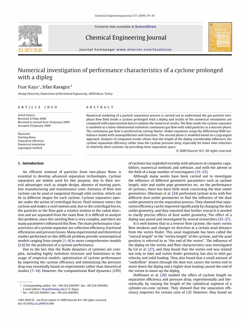
Extensive grid refinement tests have been done on the flow fieldsf cyclone so as to get grid independent solution. Typical computa-ional meshes are shown in Fig. 2 for the cyclones C1 and C2, withnd without a dipleg. Numerical experiments were carried out withhe residuals less than 10−5.
. Results and discussion
The particulate flow structure in a tangential inlet cyclone andhe effects of the dipleg length on the cyclone performance werenvestigated by using Fluent CFD code. The differential Reynoldstress model with nonequilibrium wall function was used to model
urbulence, and the Discrete Phase Model was applied to simu-ate particle motion. Predicted results were validated by comparinghem with the experimental values given in the literature [14].perating conditions (such as flow rate, dust loading, temperature,ressure, density) in numerical simulations have been taken as inFig. 2. CFD surface mesh for the cyclone with and without a dipleg.
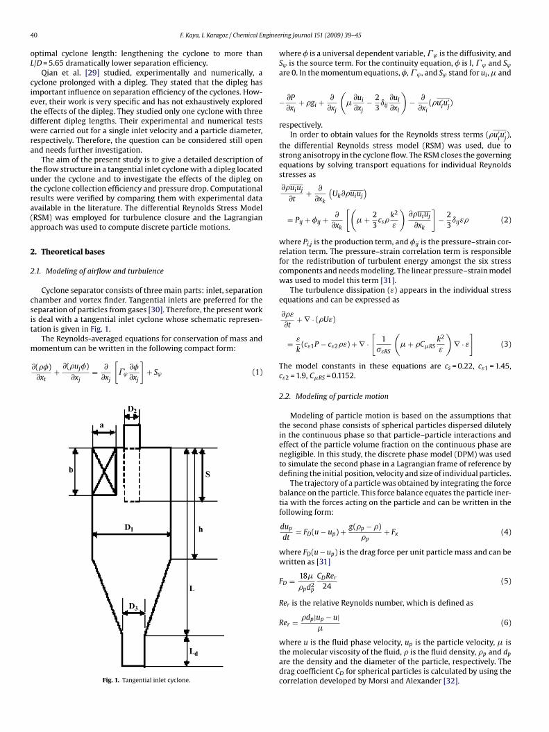
Fig. 3. Comparison between computed particle collection efficiency and experimen-tal data (Vi = 16 m/s).
the related references. Three cyclones, different in type and size,have been tested in this study. The dimensions of them are givenin Table 1. The second cyclone (C2) is the Stairmand high efficiencycyclone.
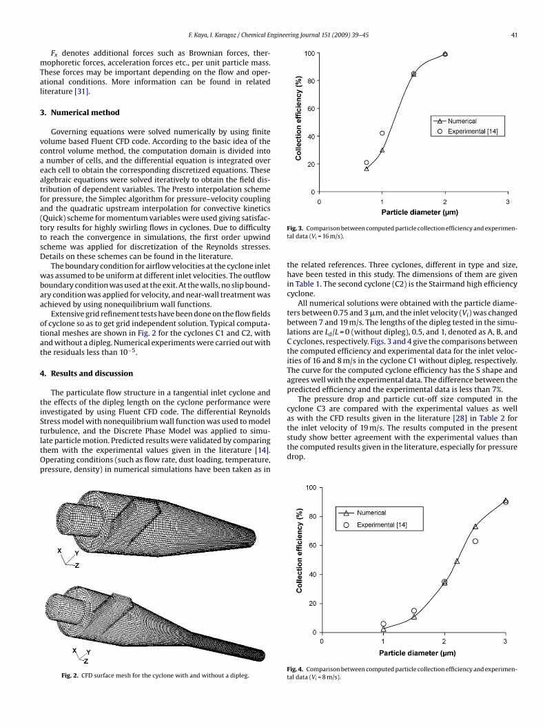
All numerical solutions were obtained with the particle diame-ters between 0.75 and 3 �m, and the inlet velocity (Vi) was changedbetween 7 and 19 m/s. The lengths of the dipleg tested in the simu-lations are Ld/L = 0 (without dipleg), 0.5, and 1, denoted as A, B, andC cyclones, respectively. Figs. 3 and 4 give the comparisons betweenthe computed efficiency and experimental data for the inlet veloc-ities of 16 and 8 m/s in the cyclone C1 without dipleg, respectively.The curve for the computed cyclone efficiency has the S shape andagrees well with the experimental data. The difference between thepredicted efficiency and the experimental data is less than 7%.
The pressure drop and particle cut-off size computed in thecyclone C3 are compared with the experimental values as wellas with the CFD results given in the literature [28] in Table 2 forthe inlet velocity of 19 m/s. The results computed in the present
study show better agreement with the experimental values thanthe computed results given in the literature, especially for pressuredrop.Fig. 4. Comparison between computed particle collection efficiency and experimen-tal data (Vi = 8 m/s).

42 F. Kaya, I. Karagoz / Chemical Engineering Journal 151 (2009) 39–45
Table 1Geometrical dimensions of the cyclones used in this study.
Model a (mm) b (mm) D2 (mm) S (mm) h (mm) L (mm) D3 (mm) D1 (mm)
C1 5 12.5 15.5 15.5 31 77 11.6 31C2 (Stairmand) 4 10 10 10 30 80 7.5 20C3 50 114 65 140 260–560–960 670–970–1370 110 200
Table 2Comparison of the computed results with experimental values for the cyclone C3.
Pressure drop (Pa) Cut-off size (�m)
ECP
mc
4
gnppi
ataiitoltif
V
xperimental [28] 3600 1.15FD [28] 3000 2.1resent CFD 3601 1.66
After these validation studies, different dipleg lengths wereodeled and the role of the dipleg on the flow structure and the
yclone performance were investigated in detail.
.1. Velocity fields of conventional and prolonged cyclones
Tangential and axial velocities are two important variables of theas flow in a cyclone. Tangential velocity creates centrifugal forceseeded for particle separation. Axial velocity makes particle trans-ort to the dustbin. The tangential velocity contours and velocityrofiles of the conventional and prolonged cyclones are presented
n Figs. 5 and 6 for the inlet velocity of 16 m/s, in the cyclone C1.The simulation results show that the length of the dipleg has
negligible influence on the tangential velocity distribution inhe cylindrical part. Although the maximum tangential velocitieslmost remain the same and a small decrease is observed with thencreasing of the dipleg length in the core of the conical part, anncreased dipleg length results in a reduced tangential velocity inhe dipleg (Fig. 5). However, the tangential velocity relatively highver the entire length of the dipleg for Ld = 38.5 compare to theongest dipleg. This also indicates that the vortex does not attaino the bottom for the longest dipleg. Fig. 6 also shows the decrease
n the tangential velocity profiles along radius at the same positionrom the bottom (z = 0.076, 0.1145 and 0.153 m).Fig. 7 shows the static pressure contours in the cyclone C1, fori = 7 m/s. The decrease in the pressure values toward bottom of the
Fig. 5. Tangential velocity contours of the cyclones A, B, C (Vi = 16 m/s, C1).
Fig. 6. Tangential velocity profiles along the radius, position at z = 0.076 m, 0.1145 mand 0.153 m (Vi = 16 m/s, C1).
dipleg is caused by the low tangential velocities below the vortexend. For the longest dipleg, a nearly constant radial pressure at thelower part of the dipleg indicates the presence of the vortex endlocation.
As can be seen from Figs. 8–10, the dipleg length consider-ably influences the axial velocity distribution. Two flow regionsare clear. Along the wall, a vortex moves down and transports thecentrifuged particles, and a second vortex moves upwards in thecenter. Figs. 9 and 10 compare the axial velocity profiles quantita-tively at the sections in the cylindrical (z = 0.03 m) and in the conical
(z = 0.053 m) parts, respectively. The effect of the dipleg is negligiblein the outer vortex; however, when the dipleg length is increased,two-peak shape axial velocity profile in the core disappears andupward velocity increases. This increase in upward velocity is pro-Fig. 7. Static pressure contours of the cyclones A, B, C (Vi = 7 m/s, C1).

F. Kaya, I. Karagoz / Chemical Engineering Journal 151 (2009) 39–45 43
Fig. 8. Axial velocity contours of the cyclones A, B, C (Vi = 16 m/s, C1).
F(
miAtlbT
F(
of separated particles and low efficiency; the same effect was foundwith higher solids loadings in cyclones [27]. On the other hand, rel-atively lower turbulence kinetic energy is seen in the conical part,which may assist improving efficiency.
ig. 9. Comparison of axial velocity profile computed at different dipleg lengthsz = 0.03 m, Vi = 16 m/s).
oted by shortcut flows into the inner vortex. Similar behaviors observed for the variation of turbulent kinetic energy (Fig. 11).s expected, the size of the low turbulent kinetic energy region at
he bottom of the cyclone increases with the increase in the diplegength. However, at the conical part, the turbulent kinetic energyecomes minimum value when the dipleg length is about 38 mm.herefore, one can expect that the lower turbulent kinetic energy in
ig. 10. Comparison of axial velocity profile computed at different dipleg lengthsz = 0.053 m, Vi = 16 m/s).
Fig. 11. Contours of turbulent kinetic energy of cyclone (Vi = 16 m/s).
the conical part will prevent the entrainment of particles and willimprove the separation process.
4.2. Performance analysis of conventional and prolonged cyclones
Fig. 12 shows the fractional efficiency curves for different dipleglengths in the cyclone C1 for the inlet velocity of 8 m/s. The lengthof the dipleg considerably affects the fractional efficiency. The pro-longed cyclone can provide more separation space, which is usefulto increase the separation efficiency. However, results obtainedfrom the numerical tests for all velocities and particle diametershave demonstrated that the best efficiency was obtained for the dip-leg length of 38.5 which corresponds the half of the cyclone height.The main reason might be the natural vortex length. In the case ofLd = 38.5 mm, the vortex end reaches the bottom of the dipleg leadsto a high collection efficiency. Further increase in the dipleg lengthmakes the vortex shorter. In this case, the vortex end attaches to thewall and crates instabilities which eventually cause re-entrainment
Fig. 12. Comparison of fractional efficiency computed at different dipleg lengths inC1 (Vi = 8 m/s).

44 F. Kaya, I. Karagoz / Chemical Engineering Journal 151 (2009) 39–45
Fc
aruHloTtoeavbdiciNrifdcit
tBiff
Fc
ig. 13. Comparison among the particle collection efficiencies of the prolonged C1yclones for different inlet velocities (dp = 1.5 �m).
The computed efficiencies under five different inlet velocitiesre shown in Figs. 13 and 14 for particle diameters of 1.5 and 2 �m,espectively. A clear trend of increasing collection efficiency is seenp to the length of about 40 mm in the cyclone C1 (Figs. 13 and 14).owever, the efficiency starts to decrease for the inlet velocities
ower than 10 m/s which corresponds to the inlet Reynolds numberf about 104, and remains almost the same for the higher velocities.hese figures also show that collection efficiency is increasing withhe increase of inlet velocity for all particle diameters at any lengthf dipleg. Higher particle diameter also leads to higher collectionfficiency, as expected. The optimal dipleg length is obtained atbout Ld/L = 0.5 for the cyclone C1 which is shorter than the con-entional Stairmand high efficiency cyclone without dipleg. As cane seen from Fig. 14, the Stairmand high efficiency cyclone (C2)oes not exhibit higher collection efficiency when the dipleg length
ncreases. The main reason is that the Stairmand high efficiencyyclone has an optimal length (L/D = 4). Therefore, further increasen the length by using a dipleg may cause a decrease in efficiency.umerical tests with larger cyclones were also carried out. The
esults of the cyclone with a diameter of 200 mm (C3) have been alsoncluded in Fig. 14. The effect of the dipleg length is not significantor this cyclone. The inlet Reynolds number is bigger than 3 × 10⁴
ue to larger inlet hydraulic diameter and L/D is about 3.35 for thisyclone. Therefore, the results from these tests showed negligiblenfluence of the dipleg length on the collection efficiency. Similarrend was also observed for the other particle diameters.
Although the dipleg length considerably influences the collec-
ion efficiency, its effect on the cyclone pressure drop is negligible.y increasing the length of dipleg, the surface for wall friction isncreased, which should result in a lower tangential velocity. There-ore, a small decrease is observed as the dipleg length increasesor higher inlet velocities, and pressure drop in the cyclone almost
ig. 14. Comparison among the particle collection efficiencies of the prolongedyclones for different inlet velocities (dp = 2 �m).
Fig. 15. Comparison among the pressure drop of the prolonged cyclones for differentinlet velocities.
remains the same for lower velocities, as can be seen in Fig. 15.Increasing in the inlet velocity also causes an increase in pressuredrop.
5. Conclusion
This study is deal with the numerical investigation of isothermalflow characteristics and particle collection efficiencies of conven-tional and prolonged cyclones. The results computed by using thedifferential RSM turbulence model were validated with the exper-imental values given in the literature. The collection efficiency andpressure drop were evaluated for various dipleg lengths at differentinlet velocities and particle diameters.
It is concluded from the results that the separation efficiency canbe improved by using a dipleg which leads to a change in flow pat-tern, for tangential inlet short cyclones. The tangential velocity andturbulence in these cyclones are reduced by a longer dipleg. How-ever, an excessive increase in the dipleg length leads the upwardaxial velocity to increase in the core region, due to vortex turning.
The static pressure values decrease toward the bottom of thedipleg due to low tangential velocities and become nearly con-stant in radial direction, where there is very low swirl, showing theexistence of the vortex end location, especially for longer dipleg.
By increasing the length of the dipleg, the surface for wall fric-tion is increased, which should results in a slightly lower tangentialvelocity. This eventually causes less pressure drop especially at highinlet velocities.
The length of the dipleg influences the cyclone performance con-siderably in cyclones shorter than the Stairmand high efficiencycyclone. The fractional separation efficiency increases up to a cer-tain level depending on particle diameter by increasing the lengthof the dipleg, due to increase of separation space. Further increasein dipleg length may cause the separation efficiency to decreaseespecially at the inlet velocities lower than 10 m/s which corre-sponds to the inlet Reynolds number of about 104, and remainsalmost the same for the higher velocities. A decrease in cone, andtherefore, dipleg diameter leads to slightly higher collection effi-ciency and pressure drop. However, the effects of the dipleg lengthdo not change with the cone dimensions.
References
[1] G.B. Shepherd, C.E. Lapple, Flow pattern and pressure drop in cyclone dustcollectors, Ind. Eng. Chem. 31 (1939).
[2] R.M. Alexander, Fundamentals of cyclone design and operation, Proc. Aus. Inst.Min. Met. NS 152–153 (1949) 203–228.
[3] W. Barth, Berechnung und Auslegung von Zyklonabscheiden auf Grund neuererUntersuchungen, BWK 8 (1956) 1–9.
[4] W. Barth, L. Leineweber, Evaluation of design of cyclone separators, Staub. Rein-halt. Luft 24 (1964) 41–55.
[5] A. Avci, I. Karagoz, Effect of flow and geometrical parameters on the collectionefficiency incyclone separators, J. Aerosol Sci. 34 (2003) 937–955.
[6] I. Karagoz, A. Avci, Modelling of the pressure drop in tangential inlet cycloneseparators, Aerosol Sci. Technol. 39 (2005) 857–865.

nginee
[[
[
[
[
[
[
[
[
[
[
[
[
[
[
[
[
[
[
[
[
F. Kaya, I. Karagoz / Chemical E
[7] M.E. Moore, A.R. Mcfarland, Performance modelling of single-inlet aerosol sam-pling cyclones, Environ. Sci. Technol. 27 (1993) 1842–1848.
[8] L.C. Kenny, R.A. Gussman, Characterizations and modelling of a family of cyclonepreseparators, J. Aerosol Sci. 26 (1995) 777–778.
[9] C.J. Stairmand, The design and performance of cyclone separators, Trans. Inst.Chem. Eng. 29 (1951) 356–383.
10] C.E. Lapple, Processes use many collector types, Chem. Eng. 58 (1951) 144–151.11] J.C. Kim, K.W. Lee, Experimental study of particle collection by small cyclones,
Aerosol Sci. Technol. 12 (1990) 1003–1015.12] C. Köning, H. Büttner, F. Ebert, Desing data for cyclones, Particle and particle
systems characterization 8 (1991) 301–307.13] S.L. Upton, D. Mark, W.D. Griffiths, A wind tunnel evaluation of the sampling
efficiencies of three bioaerosol samplers, J. Aerosol Sci. 25 (1994) 1493–1501.14] R. Xiang, S.H. Park, K.W. Lee, Effects of cone dimension on cyclone performance,
J. Aerosol Sci. 32 (2001) 549–561.15] J. Gimbun, T.G. Chuah, A. Fakhru’l-Razi, S.Y. Choong Thomas, The influence of
temperature and inlet velocity on cyclone pressure drop: a CFD study, Chem.Eng. Process. 44 (2005) 7–12.
16] A.J. Hoekstra, J.J. Derksen, H.E.A. Van Den Akker, An experimental and numer-ical study turbulent swirling flow in gas cyclones, Chem. Eng. Sci. 54 (1999)2055–2065.
17] A.L. Gong, L.Z. Wang, Numerical study of gas phase flow in cyclones with therepds, Aerosol Tech. 38 (2004) 506–512.
18] T.G. Chuah, J. Gimbun, S.Y. Choong Thomas, A CFD study the effect of cone
dimensions on sampling aerocyclones performance and hydrodynamics, Pow.Technol. 162 (2006) 126–132.19] L. Ma, D.B. Ingham, X. Wen, Numerical modelling of the fluid and particle pen-etration through small sampling cyclones, J. Aerosol Sci. 31 (2000) 1097–1119.
20] D.B. Ingham, L. Ma, Predicting the performance of air cyclones, Int. J. Eng. Res.26 (2002) 633–652.
[[
ring Journal 151 (2009) 39–45 45
21] I. Karagoz, F. Kaya, CFD investigation of the flow and heat transfer character-istics in a tangential inlet cyclone, Int. Commun. Heat Mass Transf. 34 (2007)1119–1126.
22] J.J. Derksen, H.E.A. Van den Akker, S. Sundaresan, Two-way coupled large-eddysimulations of the gas–solid flow in cyclone separators, AIChE J. 54 (2008)872–885.
23] F. Kaya, I. Karagoz, Performance analysis of numerical schemes in swirling tur-bulent flows in cyclones, Curr. Sci. 94 (2008) 1273–1278.
24] S. Obermair, J. Woisetschlager, G. Staudinger, Investigation of the flow pattern indifferent dust outlet geometries of a gas cyclone by laser Doppler anemometry,Pow. Technol. 138 (2003) 239–251.
25] A.C. Hoffmann, M. De Groot, A. Hospers, The effect of the dust collection systemon the flowpattern and separation efficiency of a gas cyclone, Can. J. Chem. Eng.74 (1996) 464–470.
26] C. Cortes, A. Gil, Modeling the gas and particle flow inside cyclone separators,Progr. Eng. Comb. Sci. 33 (2007) 409–452.
27] A. Gil, C. Cortes, L.M. Romeo, J. Velilla, Gas-particle flow inside cyclone diplegswith pneumatic extraction, Pow. Technol. 128 (2002) 78–91.
28] A.C. Hoffmann, M. De Groot, W. Peng, H.W.A. Dries, J. Kater, Advantagesand risks in increasing cyclone separator length, AIChE J. 47 (11) (2001)2452–2460.
29] F. Qian, J. Zhang, M. Zhang, Effect of the prolonged vertical tube on the separa-tion performance of a cyclone, J. Hazar. Mater. B136 (2006) 822–829.
30] S. Altmeyer, V. Mathieu, S. Jullemier, P. Contal, N. Midoux, S. Rode, J.P. Leclerc,
Comparison of different models of cyclone prediction performance for variousoperating conditions using a general software, Chem. Eng. Process. 43 (2004)511–522.31] Fluent Incorporation, Fluent user’s guide, second edition 4 (1997) 19–111.32] S.A. Morsi, A.J. Alexander, An investigation of particle trajectories in two-phase
flow systems, J. Fluid Mech. 55 (1972) 193–208.