Numerical Behaviour of Steel Columns subject to Localized Fire Loading
20
1 Abstract This paper presents the results of numerical simulations of the behaviour in a real fire of a full-size, loaded, two-dimensional, unprotected steel frame. The objective of this study is to gain confidence in the results obtained from different numerical tools, that will be used on the ROBUSTFIRE project and to ensure that these outcomes are comparable. The benchmark example is based on the paper of Franssen published in 1995 about a natural fire test on a fully loaded, two dimensional, unprotected steel framework carried out in a purpose-built compartment in Cardington [1]. The heated members are modelled by beam elements and the restraint offered by the secondary steelwork is simulated by spring elements. Geometrical and material nonlinearity and temperature dependent material properties are taken into account. The influence of the model definition, axial restraint to beam, thermal expansion and non-uniform temperature is discussed for each numerical tool. Keywords: fire, numerical, modelling, steel, structures, non-uniform temperature, beam axial restraint. 1 Introduction In the ROBUSTFIRE project, a RFCS funded European project, a general philosophy for the design of robust structures against exceptional events will be developed and practical design guidelines for its application to car parks under localised fire will be derived. The behaviour of a composite steel concrete car park subjected to fire will be studied using numerical tools, as an entire structure with a particular attention on the connections behaviour. A lot of numerical tools are available to model a composite structure subjected to fire. Some of them are specialized programs dedicated to analyzing steel structural behaviour in fire. According to Wang [2], the programs being actively developed Paper 7 Numerical Behaviour of Steel Columns subject to Localized Fire Loading A. Santiago, C. Haremza, L. Simões da Silva and J.P. Rodrigues Civil Engineering Department University of Coimbra, Portugal ©Civil-Comp Press, 2009 Proceedings of the Twelfth International Conference on Civil, Structural and Environmental Engineering Computing, B.H.V. Topping, L.F. Costa Neves and R.C. Barros, (Editors), Civil-Comp Press, Stirlingshire, Scotland
Transcript of Numerical Behaviour of Steel Columns subject to Localized Fire Loading

1
Abstract This paper presents the results of numerical simulations of the behaviour in a real fire of a full-size, loaded, two-dimensional, unprotected steel frame. The objective of this study is to gain confidence in the results obtained from different numerical tools, that will be used on the ROBUSTFIRE project and to ensure that these outcomes are comparable. The benchmark example is based on the paper of Franssen published in 1995 about a natural fire test on a fully loaded, two dimensional, unprotected steel framework carried out in a purpose-built compartment in Cardington [1]. The heated members are modelled by beam elements and the restraint offered by the secondary steelwork is simulated by spring elements. Geometrical and material nonlinearity and temperature dependent material properties are taken into account. The influence of the model definition, axial restraint to beam, thermal expansion and non-uniform temperature is discussed for each numerical tool. Keywords: fire, numerical, modelling, steel, structures, non-uniform temperature, beam axial restraint. 1 Introduction In the ROBUSTFIRE project, a RFCS funded European project, a general philosophy for the design of robust structures against exceptional events will be developed and practical design guidelines for its application to car parks under localised fire will be derived. The behaviour of a composite steel concrete car park subjected to fire will be studied using numerical tools, as an entire structure with a particular attention on the connections behaviour.
A lot of numerical tools are available to model a composite structure subjected to fire. Some of them are specialized programs dedicated to analyzing steel structural behaviour in fire. According to Wang [2], the programs being actively developed
Paper 7 Numerical Behaviour of Steel Columns subject to Localized Fire Loading A. Santiago, C. Haremza, L. Simões da Silva and J.P. Rodrigues Civil Engineering Department University of Coimbra, Portugal
©Civil-Comp Press, 2009 Proceedings of the Twelfth International Conference on Civil, Structural and Environmental Engineering Computing, B.H.V. Topping, L.F. Costa Neves and R.C. Barros, (Editors), Civil-Comp Press, Stirlingshire, Scotland

2
and used in major centres of steel structural fire research in Europe are ADAPTIC, initially developed at the Imperial College of London, UK [3], FEAST, developed at the University of Manchester, UK [4,5], VULCAN developed at the University of Sheffield, UK, and SAFIR developed at the University of Liège, Belgium [6]. The three first ones were initially developed as analysis program of steel structures at ambient temperatures and were later extended to analyse the behaviour of steel or composite structures at elevated temperature. SAFIR has always been developed for structural analyses at elevated temperatures. His predecessor is the computer program CEFICOSS [7], whose results are presented and discussed in this paper. This program can be used for both thermal analysis and structural analysis at elevated temperatures, but these two analyses cannot be coupled. These specialized programs have generally been developed according to the needs of research works, such as simulating particular experimental tests. Consequently, these programs are not able to perform all the simulations or to simulate in detail local and global behaviours. It is then necessary to choose the right program in function of the numerical needs.
ADAPTIC is particularly able to model the effect of fire after an explosion using beam and shell elements, but cannot study problems of local/distortional buckling or lateral torsional buckling, nor simulating composite construction of study detailed connection behaviour. FEAST is particularly useful to simulate the detailed connection behaviour, with all modes of local behaviour being included in the program, but it is not suitable to simulate composite structural behaviour. VULCAN is able to simulate composite construction with composite floor slabs, but its element library is limited and many modes of detailed local structural behaviour such as local or distortional buckling and connection behaviour can not be modelled. SAFIR can model various modes of flexural bending behaviour of steel, concrete and composite framed structures, but cannot model detailed connections or the large displacement behaviour of composite floor slabs in fire [2].
Commercial general finite element packages, such as ABAQUS or DIANA, have the ability to simulate complex structural behaviour under fire conditions even though they do not have special facilities to model structural behaviour in fire. All modes of structural behaviour involved in fire can be simulated thanks to a large library of finite elements which enables the creation of an efficient and detailed model, in which relevant material properties at elevated temperatures are included [2]. Temperature distributions in structures under fire can be obtained by performing a heat transfer analysis. ABAQUS is able to simulate the detailed behaviour of connections in fire and user defined subroutines enable modelling many of the special features of structural behaviour in fire. ABAQUS has been chosen to perform the numerical simulations of the ROBUSTFIRE project because of its capacity to simulate composite structures subjected to fire, as well as modelling detailed behaviour of connections in fire.
This paper presents a comparison between a specialized program dedicated to the analyses of structures submitted to fire, CEFICOSS (the predecessor of SAFIR), against the commercially available program, ABAQUS. The main objective is to validate the utilization of the ABAQUS program for steel structures submitted to elevated temperatures. This benchmark example is based on the paper by Franssen

3
published in 1995 about a natural fire test on a fully loaded, two dimensional, unprotected steel framework carried out in a purpose-built compartment in Cardington [1]. The influence of the model definition, axial restraint to beam, thermal expansion and non-uniform temperature is discussed, and the differences between the results of the two numerical software ABAQUS and CEFICOSS as well as the experimental results are illustrated. The study cases are listed in Table 1.
Parameter Study Cases
1 Model definition a) Initial structure with symmetry conditions (see Figure 5) b) Entire Cardington structure (see Figure 16)
2 Axial restraint to beam
a) Initial structure with symmetry conditions without the spring (see Figure 17(a)) b) Entire structure without the springs (see Figure 17(b))
3 Thermal expansion Initial structure with symmetry conditions, without expansion coefficient (see Figure 5)
4 Non-uniform temperature
Initial structure with symmetry conditions and uniform temperature within the cross-section (see Figure 5)
Table 1: Overview of the parametric study.
2 Description of the benchmark study
The natural fire test reported by Franssen [1] was carried out by British Steel in collaboration with the Fire Research Station. The fully loaded, two dimensional steel framework shown in Figure 1 was tested in fire in a purpose-built compartment of typical size of office accommodation (floor area of 50 m2 and ceiling height of 3.9 m). Dimensions of this steel framework were specified for a building of two or three storey in height. The beam, 4550 mm long, with a universal beam section of 406 x 178 x 54, Grade 43A, was bolted to two columns of 3530 mm tall, with a universal column section of 203 x 203 x 52, Grade 43A. M20 grade 8.8 bolts were used to provide improved resistance to loss in strength at high temperatures. Columns were pin jointed at the base and extended above the beam.
Autoclaved aerated concrete blocks were built between the column flanges to protect the web from fire, but there were only considered to give thermal insulation (non-composite behaviour). A concrete slab, which has a cross-section of 1200 x 150 mm, was also only represented because of its influence on the temperature distribution in the beam (non-composite behaviour). Lateral and sway instabilities were prevented by a subsidiary framework specially designed for.
The loads, maintained constant throughout the fire test, were applied to the two columns by a hydraulic jack and load cell placed between the top bearing plate and the load reaction frame, and to the beam, at each four equal positions along the span.
Due to the combination of ventilation openings and the thermal loading (timber cribs), equivalent fire duration of 32.5 min was achieved in the test. Maximum temperatures over 750 °C and 606 °C were observed in the beam and in the column, respectively.

4
Figure 1: Schematic layout of the loaded frame used in the Cardington tests [1].
3 Numerical Model 3.1 Numerical tools The numerical analysis is performed using the non-linear finite element package ABAQUS, v6.7 [8]. The results are compared to the experimental results and to the numerical results obtained by the software CEFICOSS [7]. Nonlinearities arise from large-displacement effects and material nonlinearities, and are taken into account on the numerical model. Moreover, temperature dependent material properties and nonlinear temperature gradient over the cross-section are also considered. 3.1.1 Finite Element Program CEFICOSS CEFICOSS (Computer Engineering of the Fire design of Composite and Steel Structures) is a special purpose finite element program developed in Liège, Belgium [7], for analysing the behaviour of structures in fire. This program integrates thermal and structural analysis and is the predecessor to the SAFIR program, which consists of an integrated thermal and structural analysis program for performing non-linear 2D and 3D analyses of steel, concrete and composite structures in fire [9].
The 2D finite difference program (thermal part of CEFICOSS) is first used for the calculation of temperatures in steel and composite steel-concrete building members exposed to fire. The heat flow from the environment to the section is assumed to be convective and radiative [1]. The structural part of the CEFICOSS program is then used to model the tested frame using beam finite elements.

5
3.1.2 Finite Element Program ABAQUS ABAQUS provides a complete and flexible solution for a large range of problems, including the analysis of structures subjected to fire. The coupled thermal-stress analysis available in this program requires the use of elements with both temperature and displacement degrees of freedom. In this study, beam elements are used, which only have displacement degrees of freedom, but no temperature degree of freedom. A heat transfer analysis is first realised to obtain the temperatures in beam and column cross-sections. The heat flow from the environment to the section is also assumed to be convective and radiative, as in the CEFICOSS program. These first thermal results are then used in the static general analysis, where temperature gradients in the beam elements cross-section are applied as predefined temperatures (see § 3.4.2). 3.2 Mechanical and Thermal Material Properties 3.2.1 Stress-Strain-Temperature Behaviour of Steel The steel stress-strain relationship at elevated temperatures is introduced in ABAQUS according to the expressions given in the EN1993-1-2:2005 [10], and illustrated in Figure 2. At room temperature, the yield stress fy considered by Franssen to simulate the experimental test is 408 MPa. This value was not experimentally measured, so five numerical simulations were carried out with CEFICOSS, using five different values: 255, 306, 357, 408 and 459 MPa [1]. The best numerical agreement with the test was reached using this yield stress equal to 408 MPa (Figure 12).
0
50
100
150
200
250
300
350
400
450
0 0.05 0.1 0.15 0.2Strain
Stre
ss (M
Pa)
20 ºC100ºC200ºC300ºC400ºC500ºC600ºC700ºC800ºC900ºC1000ºC1100ºC1200ºC
Figure 2: Nominal stress-strain relationship of steel at high temperatures.
The elastic modulus considered is 210 MPa, which decreases at high temperatures according to the reduction factor kE,θ [10]. The creep effect on the deformation of steel is included in the expressions of the EN1993-1-2:2005. A Poisson ratio constant equal to 0.3 is used. The true stress-logarithmic strain measures ( )εσ − calculated by the equation (1) is used in ABAQUS, Malvern [11]:

6
( )nomnom 1 εσσ += and ( )nom1ln εε += (1) where σnom and εnom is the nominal stress and nominal strain (Figure 2), respectively. 3.2.2 Thermal Properties of Steel The Eurocode EN 1993-1-2:2005 [10] defines the steel thermal elongation Δl/l as a function of the temperature by the equations (2), (3) and (4). In ABAQUS, it is the thermal expansion coefficient that has to be introduced. This coefficient is obtained from the expansion coefficient definition (α (θa)=ε/θa, where ε is the strain resulting from a change in steel temperature, aθ ) by dividing the expressions of the elongation (2), (3) and (4) by the current temperature, which is illustrated by the Figure 3. 42
a8
a5
a 10416.2104.0102.1/:C750ºC20ºfor −−− ×−×+×=Δ<≤ θθθ ll (2) 2
a 101.1/:C860ºC750ºfor −×=Δ≤≤ llθ (3) 3
a5
a 102.6102/:C1200ºC860ºfor −− ×−×=Δ≤< θθ ll (4)
0.000000
0.000002
0.000004
0.000006
0.000008
0.000010
0.000012
0.000014
0.000016
0 200 400 600 800 1000 1200Temperature (ºC)
Exp
ansi
on (/
ºC)
Figure 3: Thermal expansion coefficient. The conductivity and the specific heat of the steel at high temperatures are defined according to the expressions given by the EN 1993-1-2:2005 [10]. The convective heat transfer coefficient and the emissivity used by Franssen [1] and given by the EN 1993-10:1990 [13] are respectively equal to 25 W/m2K and 0.5. However, for the column flange facing the wall of the fire compartment, the emissivity is taken equal to 0.3 to account for some degree of radiative shadowing [1]. 3.2.3 Concrete properties An elastic material is assumed for the concrete as it is not taking part in the structural resistance but only plays an insulating role. The conductivity and the specific heat of the concrete slab are defined according to the EN 1992-1-2:2004 [14], with a density, an elastic modulus and a Poisson ratio equal to 2400 kg/m3, 30

7
MPa and 0.2 respectively. The concrete blocks insulating the column have particular properties: a density equal to 677 kg/m3, a constant specific heat of 1050 J/kgK and a thermal conductivity given by 0.20 + 0.0004θc W/mK [1]. 3.3 Heat Transfer analysis The heat-transfer problem analysed in ABAQUS involves conduction and boundary radiation. In these analyses, the stress/deformation state is not studied, only the temperature field is computed [8]. 3.3.1 Finite elements and Mesh discretization The two models (beam and column) are developed using 2D deformable element DC2D4, a 4-node linear heat transfer quadrilateral, and are simplified taken into account the symmetry of the section. Figure 4(a) shows the beam model where the concrete slab is modelled as it provides thermal boundary conditions. The column section model is shown in Figure 4(b) with the insulating concrete blocks between the flanges. The concrete slab and the concrete blocks are linked to the steel profiles by a tie constraint. The FE mesh is similar to the mesh used by Franssen [1] in CEFICOSS program.
a) b)
Figure 4: a) Beam and b) column cross-sections. 3.4 Static, General analysis The mechanical analysis of the structure is realised in ABAQUS by a static stress procedure in which inertia effects are neglected. Nonlinearities arise from large-displacement effects and material nonlinearity, and temperature-dependent materials are taken into account. The method to solve the nonlinear equilibrium equations

8
used by this static general analysis is the Newton’s method. A series of increments are realised in order to obtain the solution. In each increment, equilibrium is obtained by iterations. The default automatic incrementation scheme is used and increment sizes are chosen by the program on the base of computational efficiency [8]. 3.4.1 General modelling assumptions Figure 5 presents the steel frame structure for which symmetry conditions are taken into account. In order to apply these symmetry conditions at mid-span of the beam, the axial displacement in the X-direction and the rotation around Z were restrained. At the bottom of the column, the displacements in the directions X and Y are restrained.
(mm)
Figure 5: Reference frame (case 1a).
As the concrete slab and the concrete blocks in the column only provide thermal boundary conditions for the temperature, they are not modelled in the structural analysis.
Two dimension beam elements type B21 are used to define the beam and the column, with three degrees of freedom per node (X, Y, Zθ ) - Timoshenko beams. These elements have five integration points in the beam element cross-section, as shown in Figure 6.
According Franssen [1], during the experimental test, no relative rotation at the connection occurred and the temperature around the connection remained lower than elsewhere in the compartment during the fire. It is then allowed to suppose a rigid beam-to-column connection, which is modelled in ABAQUS by a coupling constraint. In order to represent the restraint offered by the secondary steelwork, a bi-linear spring is modelled using a connector element with a non-linear force-displacement behaviour, as illustrated in Figure 7. Franssen [1] defined the following spring properties: an axial stiffness equal to 6700 kN/m and an axial plastic load equal to 86 kN.

9
Figure 6: Default integration, cross-section of a beam.
-100-75-50-25
0255075
100
-100 -50 0 50 100
Displacement (mm)
Forc
e (k
N)
Figure 7: Behaviour of the spring.
3.4.2 Mechanical and Thermal Loading The mechanical loads are applied at ambient temperature and maintained constant during the fire. They corresponds to the self-weight, a vertical load on the column equal to 552 kN (P1), two vertical load on the beam equal to 39.6 kN (P2) and a uniform loading of 2.4 kN/m distributed along the beam to represent the self-weight of the concrete slab.
In CEFICOSS, the calculated temperatures can be directly used by the structural part, the cross-section being discretized using the same mesh. In ABAQUS, thermal loading can only be specified at specific points through the section or by defining the value at the origin of the cross-section and specifying the gradients [8].
Thermal loading is specified as a predefined field, as explained previously (see §3.1.2). The predefined temperature field affects temperature-dependent material properties: the elastic modulus, the stress-strain behaviour and the thermal expansion will change in function of the steel temperature.
Column and beam have temperature variations across their section, as defined by the previous heat transfer analysis. In the static analysis, temperatures are specified at the three specific points through the section [8]: i) centroid of the top flange; centroid of the web and iii) centroid of the bottom flange. Only one amplitude curve defining the evolution of the temperature in function of the time can be introduced.

10
The thermal gradients applied in the beam and column cross-sections are shown in Figure 8. The amplitude curve corresponds to the web temperatures for the beam and to the outer flange temperatures for the column.
Figure 8: Thermal gradient within the beam and column cross-sections.
Because the measured temperatures of the combustion gases were slightly lower in the vicinity of the beam-to-column connection [1], the beam has also a temperature variation along its length. In CEFICOSS, Franssen used a sinusoidal function f(x) that reduces the temperatures at the beam-to-column connection with values of 0.90 θa of the beam mid-span. In order to approximate this variation in ABAQUS, the half of the beam (case 1a, Figure 5) is divided into five parts where the temperature along each length part is constant (Figure 9).
Figure 9: Temperature gradient along the beam span.
4 Thermal results Figure 10 a) and b) show the evolution of the temperatures in flanges and in web centroid of the beam and column sections. Each dashed curve and thin plain curve represent, respectively, the experimental and the CEFICOSS results. The ABAQUS results are given by thick plain curve. The air temperature is drawn in black.
Numerical results obtained by ABAQUS show good agreement with the measured temperatures, as well as with the computed temperatures of CEFICOSS. The coefficients of variation between temperatures calculated by CEFICOSS and by ABAQUS are 2.80% for the beam and 6.26% for the column.
Mid-span Beam-to-column
connection 0.918 θa 0.95 θa 1.00 θa 0.974 θa 0.99 θa

11
a)
0
100
200
300
400
500
600
700
800
900
0 5 10 15 20 25 30Time (min.)
Tem
pera
ture
(ºC
)
AIRWeb_ExperimentalWeb_CEFICOSSWeb_ABAQUSBottom flange_ExperimentalBottom flange_CEFICOSSBottom flange_ABAQUSTop flange_ExperimentalTop flange_CEFICOSSTop flange_ABAQUS
b)
0
100
200
300
400
500
600
700
800
900
0 5 10 15 20 25 30Time (min.)
Tem
pera
ture
(ºC
)
AIRInner flange_ExperimentalInner flange_CEFICOSSInner flange_ABAQUSOuter flange_ExperimentalOuter flange_CEFICOSSOuter flange_ABAQUSWeb_ExperimentalWeb_CEFICOSSWeb_ABAQUS
Figure 10: Temperatures a) in the beam and b) in the column. Based on the considerations presented in §3.4.2, Figure 11 compares the thermal
loading introduced in the mechanical analysis of ABAQUS with the temperatures obtained from the heat transfer analyses. Because the top flange of the beam shows the lower temperatures, good approximations were preferred to the bottom flange and to the web. The same consideration is made to the column.
a)
0
100
200
300
400
500
600
700
800
900
0 5 10 15 20 25 30Time (min)
Tem
pera
ture
(ºC
) .
Web_ABAQUS_Result/AppliedBottom flange_ABAQUS_ResultBotom flange_ABAQUS_AppliedTop flange_ABAQUS_ResultTop flange_ABAQUS_Applied
b)
0
100
200
300
400
500
600
700
800
900
0 5 10 15 20 25 30Time (min)
Tem
pera
ture
(ºC
) .
Inner flange_ABAQUS_ResultInner flange_ABAQUS_AppliedOuter flange_ABAQUS_Result/AppliedWeb_ABAQUS_ResultWeb_ABAQUS_Applied
Figure 11: Applied thermal loading: a) in the beam, b) in the column.

12
5 Mechanical Results 5.1 Reference case: behaviour and validation of the numerical
model The model of the reference structure (Figure 5) is validated by comparing beam mid-span vertical displacements, column lateral displacements and beam axial load with the experimental and CEFICOSS results.
As it was explained previously, the yield stress was not experimentally measured, so five numerical simulations were carried using five different values of yield stress: 255, 306, 357, 408 and 459 MPa [1]. Figure 12 compares the measured deflection of the beam during the experimental test with the calculated deflections using CEFICOSS and ABAQUS codes for each of these values. A yield value equal to 408 MPa approximates the numerical deflection with the measured one. All the comparisons between the calculated and measured results are now done using a steel yield stress equal to 408 MPa. Because on the experimental tests, displacement transducers were switched on only at the beginning of the fire, and numerical simulations include also the deflection due to the load applied before the fire, initial difference between numerical and experimental curves are observed.
Material properties used in CEFICOSS were taken from the EN 1993-10:1990 [13], where a constant expansion coefficient α = 1.4 x 10⁻⁵ was recommended. An ABAQUS simulation was done using this constant coefficient expansion and showed results slightly closer to the CEFICOSS ones than when using the expansion coefficient variable, notably with a yield stress equal to 459 MPa (Figure 12).
0
20
40
60
80
100
120
140
0 5 10 15 20 25 30
Time (min.)
Ver
tical
disp
lace
men
t - M
id sp
an (m
m)
CEFICOSS_fy=255ABAQUS_fy=255CEFICOSS_fy=306ABAQUS_fy=306CEFICOSS_fy=357ABAQUS_fy=357CEFICOSS_fy=408ABAQUS_fy=408CEFICOSS_fy=459ABAQUS_fy=459EXP.
Figure 12: Numerical calibration of the yield stress (case 1a).

13
Figure 13 shows the vertical displacement at the mid-span of the beam and the axial compression force in the beam. A good agreement between the results from both software is shown. Both calculated fire resistances are at about 19 min. against the 20 min experimentally measured.
a)
0
20
40
60
80
100
120
140
0 5 10 15 20 25Time (min.)
Ver
tical
disp
lace
men
t - M
id sp
an (m
m)
ExperimentalCEFICOSSABAQUS
b)
0
20
40
60
80
100
120
140
0 5 10 15 20 25Time (min.)
Axi
al c
ompr
essio
n fo
rce
in b
eam
(kN
)
CEFICOSSABAQUS
Figure 13: Case 1a): a) vertical displacement of the beam in the fire test; b) calculated axial force in the beam.
The evolution of the lateral horizontal displacement at column mid-height is shown in Figure 14. Due to the elongation of the beam, the column bows laterally up to the buckling at about 19-20 min.
-80
-70
-60
-50
-40
-30
-20
-10
00 5 10 15 20 25
Time (min.)
Lat
eral
disp
lace
men
t - m
id h
eigh
t (m
m)
CEFICOSS
ABAQUS
Figure 14: Calculated horizontal displacement at mid height of column (case 1a).
14
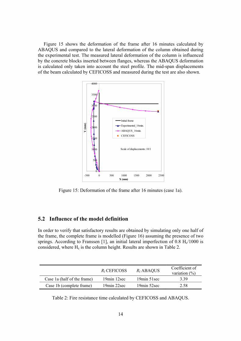
Figure 15 shows the deformation of the frame after 16 minutes calculated by ABAQUS and compared to the lateral deformation of the column obtained during the experimental test. The measured lateral deformation of the column is influenced by the concrete blocks inserted between flanges, whereas the ABAQUS deformation is calculated only taken into account the steel profile. The mid-span displacements of the beam calculated by CEFICOSS and measured during the test are also shown.
Scale of displacements: 10/1
0
500
1000
1500
2000
2500
3000
3500
4000
-500 0 500 1000 1500 2000 2500X (mm)
Y (m
m) .
Initial frame
Experimental_16min.
ABAQUS_16min.
CEFICOSS
Figure 15: Deformation of the frame after 16 minutes (case 1a). 5.2 Influence of the model definition In order to verify that satisfactory results are obtained by simulating only one half of the frame, the complete frame is modelled (Figure 16) assuming the presence of two springs. According to Franssen [1], an initial lateral imperfection of 0.8 Hc/1000 is considered, where Hc is the column height. Results are shown in Table 2.
Rf CEFICOSS Rf ABAQUS Coefficient of variation (%)
Case 1a (half of the frame) 19min 12sec 19min 51sec 3.39 Case 1b (complete frame) 19min 22sec 19min 52sec 2.58
Table 2: Fire resistance time calculated by CEFICOSS and ABAQUS.

15
Figure 16: Complete frame (case 1b). 5.3 Influence of the axial restraint to beam Mainly due to the axial restraints, the beam can not expand when temperatures increase, which develops an axial compressive force in the beam. In order to see if the frame stability is influenced or not by these restraints, the half of the frame and the complete frame are modelled without springs, as shown in Figure 17 (a) and (b).
a) b) (mm)
Figure 17: Cases 2a and 2b – No axial restraint. 5.3.1 Case 2a – half of the unrestrained frame
The axial compression load in the beam is shown in Figure 18 for the case 2a, and compared to the case 1a (with lateral restraint). Results of ABAQUS are close to the CEFICOSS one.
The fire resistance calculated by ABAQUS for the case 2a is 20min. 37sec. which is slightly higher than the fire resistance calculated by CEFICOSS, as shown in

16
Table 3. The fire resistance of the non-restraint frame is increased of 3.86% for the ABAQUS results and 2% for the CEFICOSS results without lateral restraints. The peak values reached by the axial compression forces in the beam are equal to 116.5 kN and 41.6 kN with ABAQUS results, and 124 kN and 43 kN with CEFICOSS results when restraint is present and absent respectively.
At failure, the axial compression force in the beam is reduced from 100 kN to 11 kN for ABAQUS, and 103 kN to 21 kN for CEFICOSS, when lateral restraint is removed. It shows that the stability of the frame is few influenced by the beam axial force.
0
20
40
60
80
100
120
140
0 5 10 15 20 25Time (min.)
Axi
al c
ompr
essi
on fo
rce
in b
eam
(kN
)
CEFICOSS_Restrained frameABAQUS_Case1aCEFICOSS_Unrestrained frameABAQUS_Case2a
Figure 18: Calculated axial force in the beam.
Rf CEFICOSS Rf ABAQUS Coefficient of variation (%)
Case 1a (restrained frame) 19min 12sec 19min 51sec 3.39 Case 2a (unrestrained frame) 19min 35sec 20min 37sec 5.28
Table 3: Fire resistance time calculated by CEFICOSS and ABAQUS.
5.3.2 Case 2b – Entire unrestrained frame The failure mode of this complete unrestrained frame submitted to an initial lateral imperfection (case 2b) is really different from the initial failure mode (case 1a) of the structure restraint, as shown in Figure 19.

17
(scale of displacements 4/1)
Figure 19: Calculated failure mode of the sway frame (case 2b).
As the structure sways, the fire resistance is reduced by 28.4% in CEFICOSS, against 29.8% in ABAQUS, as listed in Table 4. Good agreement between the both software is observed.
Rf CEFICOSS Rf ABAQUS Coefficient of variation (%)
Case 1a (restrained frame) 19min 12sec 19min 51sec 3.39 Case 2b (complete unrestrained frame) 13min 45sec 13min 56sec 1.33
Table 4: Fire resistance time calculated by CEFICOSS and ABAQUS.
5.4 Influence of the thermal expansion The influence of the thermal expansion on the fire resistance of the frame is tested by modelling the initial structure represented in Figure 5, without any thermal expansion coefficients (case 3).
The total thermal expansion from a reference temperature is defined by the thermal expansion coefficients, which generate thermal strains. The ABAQUS results reinforce the conclusion of Franssen, saying that the expansion coefficients have a significant effect [1]. Indeed, without expansion coefficients:
i) The fire resistance increases from 19min. 51sec. (case 1a) up to the end of the analysis – 30 min. (case 3) and probably more because of the cooling of the steel as the fire decays [1]. However, because no experimental temperatures were measured after 30 min., the numerical analyses were also limited to this time.
ii) The axial compression load in the beam increases much less from a maximum value of 116.5kN after 12 minutes (case 1a) to a maximum value of 17kN after 18 minutes (case 3). The value at ambient temperature stays constant and equal to 7kN;
iii) The lateral displacement of the column decreases because of the absence of the thermal expansion of the beam that was pushing the column outward.
ABAQUS obtains results quite close to the CEFICOSS ones. The higher difference (20%) is in the maximum axial compression load value in the beam: CEFICOSS have 21kN after 17 minutes, and ABAQUS 17kN after 18 minutes. However, the stability of the frame is few influenced by the axial force, as it was confirmed in § 5.3.1.
18
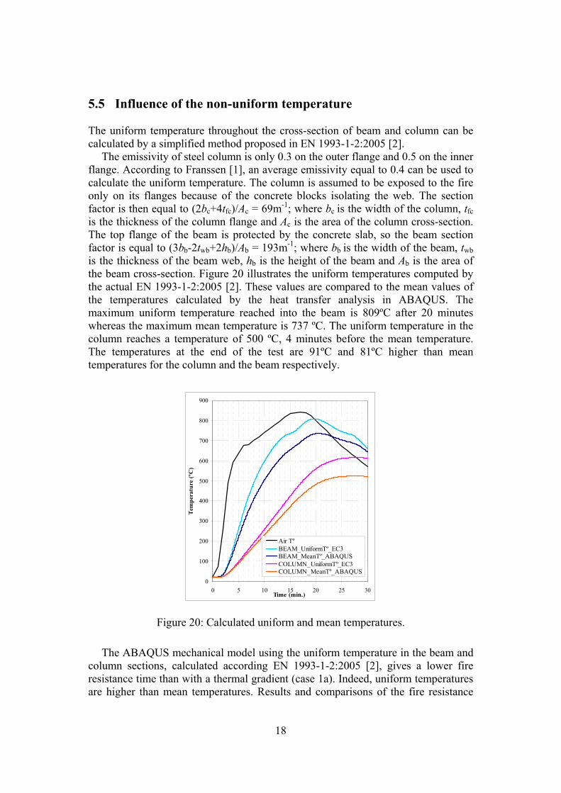
5.5 Influence of the non-uniform temperature The uniform temperature throughout the cross-section of beam and column can be calculated by a simplified method proposed in EN 1993-1-2:2005 [2].
The emissivity of steel column is only 0.3 on the outer flange and 0.5 on the inner flange. According to Franssen [1], an average emissivity equal to 0.4 can be used to calculate the uniform temperature. The column is assumed to be exposed to the fire only on its flanges because of the concrete blocks isolating the web. The section factor is then equal to (2bc+4tfc)/Ac = 69m-1; where bc is the width of the column, tfc is the thickness of the column flange and Ac is the area of the column cross-section. The top flange of the beam is protected by the concrete slab, so the beam section factor is equal to (3bb-2twb+2hb)/Ab = 193m-1; where bb is the width of the beam, twb is the thickness of the beam web, hb is the height of the beam and Ab is the area of the beam cross-section. Figure 20 illustrates the uniform temperatures computed by the actual EN 1993-1-2:2005 [2]. These values are compared to the mean values of the temperatures calculated by the heat transfer analysis in ABAQUS. The maximum uniform temperature reached into the beam is 809ºC after 20 minutes whereas the maximum mean temperature is 737 ºC. The uniform temperature in the column reaches a temperature of 500 ºC, 4 minutes before the mean temperature. The temperatures at the end of the test are 91ºC and 81ºC higher than mean temperatures for the column and the beam respectively.
0
100
200
300
400
500
600
700
800
900
0 5 10 15 20 25 30Time (min.)
Tem
pera
ture
(ºC
)
Air TºBEAM_UniformTº_EC3BEAM_MeanTº_ABAQUSCOLUMN_UniformTº_EC3COLUMN_MeanTº_ABAQUS
Figure 20: Calculated uniform and mean temperatures.
The ABAQUS mechanical model using the uniform temperature in the beam and column sections, calculated according EN 1993-1-2:2005 [2], gives a lower fire resistance time than with a thermal gradient (case 1a). Indeed, uniform temperatures are higher than mean temperatures. Results and comparisons of the fire resistance

19
obtained by the numerical tools CEFICOSS and ABAQUS using uniform temperatures (case 4) and temperature gradients in the cross-section (case 1a) are presented in Table 5.
Rf CEFICOSS Rf ABAQUS Coefficient of variation (%)
Case 1a (gradient of temperature) 19min 12sec 19min 51sec 3.39 Case 4 (uniform temperature) 18min 15sec 19min 4.11
Table 5: Fire resistance time calculated by CEFICOSS and ABAQUS.
6 Concluding remarks This paper presented a comparison between a specialized program dedicated to the analyses of structures submitted to fire, CEFICOSS (the predecessor of SAFIR), against a commercially available program, ABAQUS. The main objective was to validate the utilization of the ABAQUS program for steel structures submitted to elevated temperatures. The simple 2D steel frame studied in this paper was based on the paper of Franssen published in 1995 about a natural fire test on a fully loaded, two dimensional, unprotected steel framework carried out in a purpose-built compartment in Cardington [1]. The influence of the model definition, axial restraint to the beam, thermal expansion and non-uniform temperature were discussed.
ABAQUS performed well the heat transfer analysis to obtain temperature distributions in structures, and showed a good ability to simulate steel structural behaviour under fire conditions using beam elements.
Some of the differences between the results of the commercial program ABAQUS and the fire dedicated program CEFICOSS could be explained by three main reasons. First, the CEFICOSS and experimental results were only available via the paper of Franssen [1] and all values were directly measured on this paper. Secondly, the temperature gradients in cross-sections were approximated in ABAQUS as they only could be defined into three dependant points in the cross-section whereas CEFICOSS could directly apply all the temperature results obtained by the heat transfer analysis. Finally, CEFICOSS being the predecessor of SAFIR, with a version from 1995, some differences relate to the improvements that took place in the last 14 years in terms of numerical capabilities and techniques. References [1] J.M. Franssen, G.M.E. Cooke, D.J. Latham, “Numerical Simulation of a Full
Scale Fire Test on a Loaded Steel Framework”, Journal of Constructional Steel Research, 35, 377-408, 1995.
[2] Y.C. Wang, “Steel and composite structures – Behaviour and design for fire safety”, Spon Press, 2002.
[3] B.A. Izzuddin, L. Song, A.S Elnashai, and P.J Dowling, “An Integrated Adaptive Environment for Fire and Explosion analysis of steel frame – Part 2:

20
verification and application”, Journal of Constructional Steel Research, 53, 87-111, 2000.
[4] T.C.H. Liu, “Theoretical Modelling of Steel Bolted Connection under Fire Exposure”, Proceedings of International Conference of Computational Methods in Structural and Geotechnical Engineering Mechanics, Hong Kong, 1994.
[5] T.C.H. Liu, “Finite element modelling of behaviour of steel beams and connections in fire”, Journal of Constructional Steel Research, 36(2), pp.181-199, 1996.
[6] J.M. Franssen, V.K.R. Kodur, and J. Mason, “User Manual for SAFIR 2001, A computer program for analysis of structures submitted to the fire”, University of Liège, Belgium, 2000.
[7] J.M Franssen, “Etude du comportement au feu des structures mixtes acier béton”, PhD Thesis, University of Liège, 1987.
[8] ABAQUS Theory Manual & Users Manuals, Version 6.7, Hibbitt, Karlsson and Sorensen, Inc. USA, 2007.
[9] L. Lim, A. Buchanan, P. Moss, J.M. Franssen, “Numerical modelling of two-way reinforced concrete slabs in fire”, Engineering Structures, 26, 1081-1091, 2004.
[10] EN 1993-1-2:2005, “Eurocode 3: Design of steel structures – Part 1-2: General rules – Structural fire design”, European committee for standardization, April 2005.
[11] L.E. Malvern, “Introduction to the mechanics of a continuous medium”, Englewood Cliffs, NJ: Prentice-Hall, 1969.
[12] M. Gillie, “The Behaviour of Steel-Framed Composite Structures in Fire Conditions”, PhD Thesis, University of Edinburgh, UK, 2000.
[13] EN 1993-10:1990, “Eurocode 3: Design of Steel Structures, Part 10: Structural Fire Design”, Draft April 1990.
[14] EN 1992-1-2:2004, “Eurocode 2: Design of concrete structures – Part 1-2: General rules – Structural fire design”, European committee for standardization, December 2004.