Numerical and experimental analysis of non-circular gears and cam-follower systems as function...
21
MECHMT-D-06-00269 Mechanism and Machine Theory (REVISED) Numerical and Experimental Analysis of Non-Circular Gears and Cam-Follower Systems as Function Generators Erika Ottaviano 1 , Domenico Mundo 2 , Guido A Danieli 2 and Marco Ceccarelli 1 1 LARM: Laboratory of Robotics and Mechatronics, University of Cassino, Cassino (Fr) – Italy e- mail: ottaviano/[email protected] 2 Department of Mechanics, University of Calabria, Arcavacata di Rende (Cs) – Italy e-mail: d.mundo/[email protected] Abstract The paper shows an analysis of two mechanisms that are typically used as function generators. The former consists of a pair of non-circular gears, which drives a slider- crank mechanism, the latter is a cam-follower system. Both mechanisms are designed to obtain a specific motion law. In this paper the proposed application is to generate a pulsating blood flow during cardiopulmonary by-pass for cardiac surgery. The prescribed motion law can be obtained by a volumetric pump, which can be used to modulate the blood flow in external circulation machines. The reciprocating motion consists of a quick forward stroke, corresponding to the Systolic phase, and a slow return stroke, corresponding to the Diastolic phase. The study has been focused on specific transmission characteristics that are related to a mechanical blood pumping design. In particular, experimental tests have been analyzed to understand benefits and drawbacks for using non-circular gears and polynomial cams in pure mechanical transmissions with limited motion regulation but with specific prescribed motion law. The contribution of the paper can be recognized in comparing numerically and experimentally a traditional cam transmission with a non-circular gear solution to show proper operation feasibility for both solutions without using complex control equipment, even for a robust/reliable demanding application like a blood pumping system. Keywords: Mechanism Analysis, Non-Circular Gears, Cam-follower Systems, Function Generators, Experimental Mechanics 1
Transcript of Numerical and experimental analysis of non-circular gears and cam-follower systems as function...

MECHMT-D-06-00269 Mechanism and Machine Theory (REVISED)
Numerical and Experimental Analysis of Non-Circular
Gears and Cam-Follower Systems as Function Generators
Erika Ottaviano1, Domenico Mundo2, Guido A Danieli2 and Marco Ceccarelli1
1 LARM: Laboratory of Robotics and Mechatronics, University of Cassino, Cassino (Fr) – Italy e-
mail: ottaviano/[email protected] 2 Department of Mechanics, University of Calabria, Arcavacata di Rende (Cs) – Italy
e-mail: d.mundo/[email protected]
Abstract
The paper shows an analysis of two mechanisms that are typically used as function
generators. The former consists of a pair of non-circular gears, which drives a slider-
crank mechanism, the latter is a cam-follower system. Both mechanisms are designed to
obtain a specific motion law. In this paper the proposed application is to generate a
pulsating blood flow during cardiopulmonary by-pass for cardiac surgery. The
prescribed motion law can be obtained by a volumetric pump, which can be used to
modulate the blood flow in external circulation machines. The reciprocating motion
consists of a quick forward stroke, corresponding to the Systolic phase, and a slow
return stroke, corresponding to the Diastolic phase. The study has been focused on
specific transmission characteristics that are related to a mechanical blood pumping
design. In particular, experimental tests have been analyzed to understand benefits and
drawbacks for using non-circular gears and polynomial cams in pure mechanical
transmissions with limited motion regulation but with specific prescribed motion law.
The contribution of the paper can be recognized in comparing numerically and
experimentally a traditional cam transmission with a non-circular gear solution to show
proper operation feasibility for both solutions without using complex control equipment,
even for a robust/reliable demanding application like a blood pumping system.
Keywords: Mechanism Analysis, Non-Circular Gears, Cam-follower Systems,
Function Generators, Experimental Mechanics
1

1 INTRODUCTION
A function generator is a mechanism synthesized to satisfy the optimal Input/Output
relationship for a specified application. In many industrial applications a purely
mechanical device is often desirable to obtain the required motion with robust
operation, like for example for automatic equipment in printing presses, textile industry,
packaging machines, quick-return mechanisms [1-3]. The generation of a specific
motion law is essential also in recreational equipments and rehabilitation devices, in
which the maximization of human output is fundamental.
Several mechanical devices can be designed to obtain a prescribed motion law of the
output element. Among them, cam-follower mechanisms are widely used in modern
machinery. These devices can reproduce almost any characteristics of the follower’s
motion and they are not particularly difficult to design and build. Their manufacturing
costs are rather limited, as well as the number and dimensions of moving parts [4,5].
When a mechanical system is used to obtain a required motion of the output link, non-
circular gears are another possible choice. The application of non-circular gears in
function generating mechanisms has been proposed and discussed in [6,7]. By designing
a pair of non-circular gears, which are able to perform a proper gear ratio function, the
output member of a mechanism can be effectively forced to move according to a
prescribed law of motion, when operated at a constant input-velocity, [8,9]. In typical
arrangements, a pair of variable radius pitch curves is synthesized to drive a slider-crank
mechanism according to a prescribed motion law. For many applications non-circular
gears provide some benefits over cams, although they are more difficult to design and
expensive to manufacture. The main advantages are the lower weight-to-strength ratios
and absence of gross separation or decoupling of moving parts [10].
In this paper, two function generators are designed to drive a flow modulator for
external blood circulation, during cardiopulmonary by-pass for cardiac surgery.
In the first mechanism, the output motion is obtained by using a pair of non-circular
gears. The pitch curves synthesis is formulated by means of the inverse kinematic
analysis of the system. Then, the teeth profiles are generated by assuming the pressure
angle to be constant along each tooth, but variable from tooth to tooth.
The second mechanism consists of a cam-follower system, which is commonly used
to achieve complex and very variable transmission laws between input rotative shafts
2

and output linear or rotative motion of the follower. The cam has been designed
according to the prescribed motion law and with suitable values for the base and
follower radii. Both mechanisms have been prototyped by means of a CNC milling
machine. Suitable test-beds have been designed at Department of Mechanical
Engineering, University of Calabria in Arcavacata di Rende and LARM: Laboratory of
Robotics and Mechatronics in Cassino in order to carry out experimental validation. An
analysis and comparison for both mechanical devices have been carried out at
University of Cassino in order to validate the used design methods and to compare main
characteristics of the two mechanical systems, according to the specific proposed
application. Preliminary result of the proposed application has been presented in [11].
2 DESCRIPTION OF THE REQUESTED MOTION LAW
The application task is to generate a pulsating blood flow during cardiopulmonary
by-pass for cardiac surgery. In human body, the blood flow follows a pulsating law
consisting of two phases known as the Systole and the Diastole [12]. During the systolic
phase, the cardiac muscle contracts in order to pump blood into the cardiovascular
circuit, and during the diastolic phase the heart’s relaxation occurs. In physiological
conditions, the contraction phase is quicker than the relaxation one, being the duration
ratio about 1:2.
Starting point of the design process is the definition of the Input/Output relationship,
i.e. the motion that the function generator must satisfy. Therefore, the aim is to design a
mechanical device, which can be able to drive the piston of a pump that is used to
modulate the blood flow during the external circulation [13].
Several mechanisms have been proposed to reproduce these characteristics in the
external blood circulation, as reported in [14]. A roller pump can be used in order to
generate a constant flow, and then to modulate it by means of a volumetric pump. The
periodic motion law for the modulator’s piston can be determined on the basis of emo-
dynamic considerations, [15]. The required law of motion consists of two phases,
corresponding to the forward and return stroke of the piston. The two phases are defined
separately by two polynomial functions. Four boundary conditions, listed in Table 1,
have been properly established at each extreme of the two regions to guarantee
3

continuity between the two curves up to the first derivative of the acceleration, so that a
regular dynamic behavior of the proposed mechanisms could be expected. In order to
fulfill the boundary conditions, i.e. displacement, velocity, acceleration and jerk values
at each extreme, the order of such polynomials is set to 7, according to the following
expression
( ) ∑=
=7
0i
ii tats (1)
in which t is the time parameter and the coefficients ai have been determined for both
strokes, by imposing the boundary conditions of Table 1 as listed in Table 2.
The proposed motion law is characterized by a maximum displacement of 40 mm and a
period of 1 second. In order to obtain a blood flow similar to the one that a healthy heart
usually produces, different durations have been assigned to the strokes. In particular, the
return stroke has been assumed with duration of 0.667 sec, and the forward one lasts
0.333 sec. Figure 1 shows the motion law characteristics for the proposed application.
Table 1. Boundary conditions for the polynomial function in Eq.(1)
Time (s) Displacement
s(mm)
Velocity
(mm/s)
Acceleration
(mm/s2)
Jerk
(mm/s3)
0t = 40 0 -800 10000
3/2t = 0 0 800 10000
1t = 40 0 -800 10000
Table 2. Coefficients of the polynomial function in Eq.(1)
Time (s) a7 a6 a5 a4
3/2t0 <≤ 6243.75 -14568.75 13365 -6087.5
1t3/2 <≤ -702000 4095000 -10142280 13822000
Time (s) a3 a2 a1 a0
3/2t0 <≤ 1666.66667 -400 0 40
1t3/2 <≤ -11193533 5388000 -1428000 160853.333
4

Fig. 1. Requested motion law for the output element: a) displacement; b) velocity;
c) acceleration; d) jerk.
The polynomial of 7th order has been imposed to ensure a prescribed behavior even
in term of limiting vibrating output with the aim to reproduce the smooth of the natural
blood pumping.
3 DESIGN FORMULATION FOR NON-CIRCULAR GEARS
In typical arrangements, a pair of non-circular gears is used to drive a slider-crank
mechanism, so that the piston is forced to move according to a specific law of motion.
The design of these mechanisms consists of two phases, namely the synthesis of the
pitch curves, starting from the requested law of motion, and the determination of teeth
profiles.
3.1 Synthesis of the pitch curves
The synthesis of the pitch curves can be formulated by means of the inverse
kinematic analysis of the mechanism. Starting point is the prescribed law of motion of
5

the piston s(t). In the proposed application, the purpose is to provide the piston of a
volumetric pump with the specific law of motion that is represented in Fig. 1.
Referring to the schemes in Fig.2, the relation between the displacement of the
connecting-rod end D and the rotational angle δ on the driven gear is
( ) ( ) ( )( )⎥⎦⎤
⎢⎣⎡ δλ−−
λ−δ−=δ 22
D sin111cos1rs (2)
where λ is the crank-to-rod ratio, equal to 0.2 in this application, the crank length r = 20
mm, as it can be assigned on the basis of the stroke value. The constant angular velocity
of the driving gear is ω,while Ω is the variable angular velocity of the driven gear.
By coupling the analytical law sD(δ) and numerical expression sD(t) in Eq.(1), the
time dependence of the rotational angle of the driven gear can be deduced. The
rotational angle θ of the driving gear can be evaluated as
( ) tT2tt π
=ω=θ (3)
where T is the period of the driving gear motion that has been fixed equal to 1 second in
this application. Once δ(t) and θ(t) are known, the variable gear ratio can be evaluated
as a function of θ in the form
Fig. 2. Schematic representation of the mechanism.
6

( )( ) ( )( )tdtdt
θδ
=ωΩ
=θτ (4)
Figure 3 shows the computed variable gear ratio that is characterized by a variation
between 0.66 and 1.77, with an average value equal to 1.00.
By imposing that the contact points of the pitch curves have the same velocity, a first
relation between the pitch curves radii can be formulated as
( ) ( ) ( )( )( )θδθ
=ωθΩ
=θτ2
1
RR
(5)
where R1 (θ) and R2 (δ(θ)) are the pitch curve radii at the time t=θ/ω.
In order to determine the shape of the pitch curves a second relation can be obtained
by considering the constant distance rc between the centers of rotation
( ) ( )( ) c21 rRR =θδ+θ (6)
In this application the constant value rc=100 mm has been assumed.
The pitch curves for the requested output curve of Fig. 1 can be obtained by
combining equations 4 and 5. The synthesized curves are shown in Fig. 4.
Fig. 3. Gear ratio as a function of the driving gear angle.
7

Fig. 4. Computed pitch curves generating the output curve of Fig. 1.
It is worth to note that the pitch curves represented in Fig. 4 have the same length,
since the average value of the gear ratio function is equal to one. This ensures that each
tooth of the driving gear always meshes with the corresponding tooth on the driven gear.
3.2 Determination of Tooth Profiles
The numerical generation of tooth profiles in non-circular pitch curves is based on
the description of the meshing evolution and can be performed according to several
methods [16]. In this paper the mathematical model of tooth profiles has been based on
the following differential equation
( ) ( ) ( )⎥⎦⎤
⎢⎣⎡ α
θ−θα=
θtan
ddRRcos
ddy 1
12 (7)
where dθ refers to the rotation of the driving gear, and dy is the corresponding
displacement of the contact point, as projected onto the normal direction to the curve
crossing O1 and O2 [17]. The angle α is the constant pressure angle. Equation (7) can be
integrated numerically by starting from the intersection point of a tooth profile with the
pitch curve. Points can be derived as a pair in the conjugate profiles, by means of a
coordinate transformation that is based on two suitable rotation matrices.
8

Once established the contact point between the first teeth pair on the pitch curves and
given the diameter pitch and number of teeth, the intersection point of any profile with
the pitch curves can be determined straightforward .
The integration process stops when one of the following conditions occurs: the radial
dimension of a tooth exceeds the established upper bound; the distance between the
contact point and gear centre is stationary. The last condition refers to undercutting
conditions. By using the above-mentioned procedure for the pitch curves in Fig. 4 and
assuming a number of teeth equal to 30, the profiles are generated as represented in Fig.
5.
Since the tangent line to the pitch curves at the contact points shows variable
direction, the pressure angle is varied from tooth to tooth, so that the angle between the
pressure line and the normal to the pitch curves has always the same prescribed value of
20 degree [18]. Of course, two meshing teeth on different gears have the same pressure
angle.
In order to check for the continuity of power transmission, the contact ratio can be
evaluated through the parameter
1i
1i,i
1i
i,1i1c+
+
−
−
θ∆
θ∆+
θ∆
θ∆+= (8)
Fig. 5. Designed teeth profiles
9
where ∆θi-1,i is the rotation of the gear 1 while the meshing evolves from the beginning
of the contact on the ith tooth to the end on the (i-1)th tooth; ∆θi,i+1 corresponds to i th and
(i+1) th teeth; ∆θi-1 is the rotation angle referring to (i-1)th tooth; and ∆θi+1 is for (i+1)th
tooth.
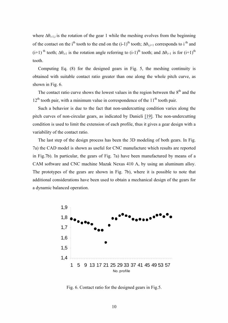
Computing Eq. (8) for the designed gears in Fig. 5, the meshing continuity is
obtained with suitable contact ratio greater than one along the whole pitch curve, as
shown in Fig. 6.
The contact ratio curve shows the lowest values in the region between the 8th and the
12th tooth pair, with a minimum value in correspondence of the 11th tooth pair.
Such a behavior is due to the fact that non-undercutting condition varies along the
pitch curves of non-circular gears, as indicated by Danieli [19]. The non-undercutting
condition is used to limit the extension of each profile, thus it gives a gear design with a
variability of the contact ratio.
The last step of the design process has been the 3D modeling of both gears. In Fig.
7a) the CAD model is shown as useful for CNC manufacture which results are reported
in Fig.7b). In particular, the gears of Fig. 7a) have been manufactured by means of a
CAM software and CNC machine Mazak Nexus 410 A, by using an aluminum alloy.
The prototypes of the gears are shown in Fig. 7b), where it is possible to note that
additional considerations have been used to obtain a mechanical design of the gears for
a dynamic balanced operation.
1,4
1,5
1,6
1,7
1,8
1,9
1 5 9 13 17 21 25 29 33 37 41 45 49 53 57No. profile
Fig. 6. Contact ratio for the designed gears in Fig.5.
10
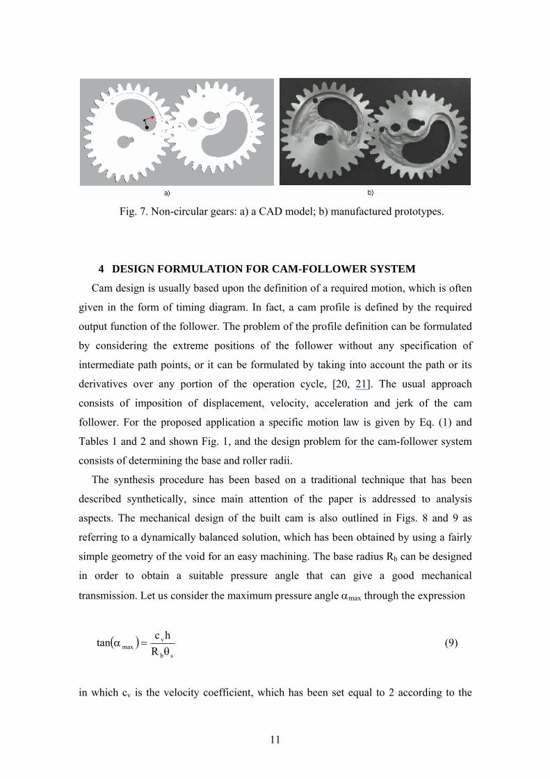
Fig. 7. Non-circular gears: a) a CAD model; b) manufactured prototypes.
4 DESIGN FORMULATION FOR CAM-FOLLOWER SYSTEM
Cam design is usually based upon the definition of a required motion, which is often
given in the form of timing diagram. In fact, a cam profile is defined by the required
output function of the follower. The problem of the profile definition can be formulated
by considering the extreme positions of the follower without any specification of
intermediate path points, or it can be formulated by taking into account the path or its
derivatives over any portion of the operation cycle, [20, 21]. The usual approach
consists of imposition of displacement, velocity, acceleration and jerk of the cam
follower. For the proposed application a specific motion law is given by Eq. (1) and
Tables 1 and 2 and shown Fig. 1, and the design problem for the cam-follower system
consists of determining the base and roller radii.
The synthesis procedure has been based on a traditional technique that has been
described synthetically, since main attention of the paper is addressed to analysis
aspects. The mechanical design of the built cam is also outlined in Figs. 8 and 9 as
referring to a dynamically balanced solution, which has been obtained by using a fairly
simple geometry of the void for an easy machining. The base radius Rb can be designed
in order to obtain a suitable pressure angle that can give a good mechanical
transmission. Let us consider the maximum pressure angle αmax through the expression
( )sb
vmax R
hctan
θ=α (9)
in which cv is the velocity coefficient, which has been set equal to 2 according to the
11
specific motion law in Eq.(1); h is the maximum stroke; θs is the rise angle. By
choosing a maximum value of 30 deg for the pressure angle, [22], Eq.(9) gives a value
for Rb equal to 65 mm. A value of 25 mm has been chosen for the roller radius, in
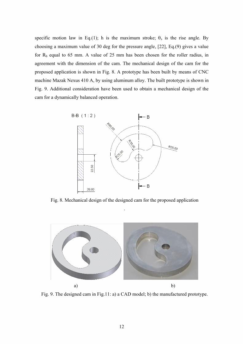
agreement with the dimension of the cam. The mechanical design of the cam for the
proposed application is shown in Fig. 8. A prototype has been built by means of CNC
machine Mazak Nexus 410 A, by using aluminum alloy. The built prototype is shown in
Fig. 9. Additional consideration have been used to obtain a mechanical design of the
cam for a dynamically balanced operation.
Fig. 8. Mechanical design of the designed cam for the proposed application
.
a) b)
Fig. 9. The designed cam in Fig.11: a) a CAD model; b) the manufactured prototype.
12

5 EXPERIMENTAL TESTS
Low-cost test-beds have been designed and settled up at LARM in Cassino, Italy.
They have been used for experimental tests and validation of cams, [11; 23-26]. In this
paper, a low-cost test bed for experimental validation is presented for tests on both the
herein designed cam-follower and non-circular gears systems, as shown in the scheme
of Fig. 10. In particular, in order to compare kinematic performances of the two
mechanical transmissions the same acquisition system, servomotor and sensors have
been used for both test-beds. For each test-bed configuration it has been thought
convenient to use LabView software with NI 6024E Acquisition Card, in order to work
with suitable virtual instruments, which can manage commercial sensors. Thus, an
accelerometer S1 has been used to determine the output acceleration of the follower.
Signal conditioner and amplifier denoted by A1 in Fig. 10 have been used in order to
provide suitable power supply to S1 and to reduce the noise in the measured signal. The
same DC motor with servo amplifier, an encoder S2 and a tachometer S3 have been used
in order to give and to monitor the input motion. In particular, the encoder gives the
possibility to monitor the angle of the input shaft, whereas the tachometer is used to
monitor the angular velocity of the input shaft. In addition, three control modes can be
selected by DIP switches on board of the servo amplifier: - speed control using
tachometer signals or encoder signals; - compensated speed control; - torque or current
control. In addition, signal conditioner and amplifier A2 have been used in order to
provide suitable power supply to S2 and S3 and to reduce the noise in the measured
signal. A linear transducer, S4 has been used only in the test-bed configuration with the
non-circular gears.
The test-bed with non-circular gears shown in Fig. 11 consists of a base, on which
the driving and driven shafts are supported. It is fundamental that the distance between
the two axes has the nominal value of 100 mm, otherwise an irregular transmission can
be obtained. On the same base a slider-crank mechanism has been assembled, so that a
crank radius of 20 mm is obtained on the driven gear. Figure 12 shows a particular of
the test-bed with the cam transmission system.
The displacement history of a follower point in the cam system gives the output
function as related to the cam profile. Once the cam transmission operates properly, the
cam profile is the characterizing element of the transmission operation of a cam system.
13

Thus, it is not necessary to ensure an accurate cam profile fulfilling the prescribed
motion law. Since the cam has been manufactured by means of a CNC machine to
obtain the prescribed polynomial profile, the output motion of the follower has been
verified by verifying accurately the cam profile of the built prototype before its use.
Even zero eccentricity between cam and follower has been verified in the assembling of
the test-bed in Fig. 12.
Since the aim of the transmission systems is to generate accurately a prescribed
function, operation efficiency can be controlled/ensured mainly by looking at the
fulfillment of the motion characteristics that give the function. Of course, this require a
consideration of dynamic conditions, but they can be synthetically considered by
looking at the actuator torque that gives the prescribed function as output motion. Thus,
the feasibility of the non kinematical aspects can be considered by looking at the
feasibility of the actuation torque both in terms of practical possibility for a commercial
motor and a proper dynamic operation. Both of them can be checked by looking at the
time history of the actuation torque. Thus, the proposed test-beds allow also to develop
considerations about dynamical aspects for both transmission systems in order to take
into account those aspects, the input torque has been also monitored for the proposed
experimental results.
Fig. 10. A scheme for the sensored test-bed for mechanical transmission system testing.
(S1 is an accelerometer; S2 is an encoder; S3 is a tachymeter; S4 is a linear transducer.)
14

Fig. 11. A view of the test-bed with non-circular gears of Fig. 7.
Experimental tests have been carried out on the mechanical test-bed transmission
systems of Figs. 11 and 12 by imposing the input velocity to be a constant value
according to design requirements. Information about acceleration is then obtained by
using an accelerometer; actuation torque has been monitored by measuring the DC
motor current. In Fig. 13 an experimental test is reported with the non-circular gears of
Fig. 11. In particular, the input torque and follower acceleration have been reported.
Fig. 12. A view of the test-bed with the cam in Fig. 9.
15

a) b)
Fig.13. Experimental results of the operation of the non-circular gears system in
Fig.11: a) input torque; b) follower acceleration.
Figure 14 shows experimental results that have been obtained with the cam system
in Figs. 8 and 12. In particular, Fig. 14a) shows the input torque versus time; Fig. 14b)
shows the measured acceleration of the follower.
A comparative analysis of the two different mechanical systems shows a good
match with respect to the prescribed motion characteristics. The comparison between
numerical and experimental results for the follower acceleration for both mechanical
transmissions is reported in Fig. 15. Discrepancies between theoretical and
experimental results on acceleration plots can be considered due mainly to dynamical
aspects that are not taken into account in the proposed kinematic analysis.
a) b)
Fig.14. Experimental results of the operation of the cam-follower system in Fig.12:
a) input torque; b) follower acceleration.
16

a) b)
Fig. 15. A comparison between theoretical and experimental results for the follower
acceleration: a) non-circular gears; b) cam system. (dotted line is for theoretical
acceleration; continuous line is for experimental acceleration)
The results that are plotted in Fig. 15 have been considered satisfactory as matching
the prescribed data in Fig. 1, since the function shape is properly obtained and
deviations are very limited in the pulsing peaks, as easily observable also in Fig.15.
The relationship between the experimental and theoretical displacement of the slider
is shown in Fig.16. The experimental curve is well fitted on the theoretical one: the
values of 0.081 mm and 0.06 mm are the average and the standard deviation of the
difference between the measured and theoretical curves, respectively. The maximum
deviation between the two curves is equal to 0.3 mm.
By looking at numerical simulations in Fig. 1 and mainly at experimental results in
Figs.13 to 16 a comparison of characteristics can be outlined in term of the following
observations:
- non-circular gears show more vibratory response when the input velocity is not
exactly the prescribed value for the design solution;
- cam transmission has a limited maximum value for the input velocity, which is
due to the condition given by the spring ensuring proper contact between cam
profile and follower contact surface;
- cam transmissions have a compact design with reduced dimensions and they can
ensure a robust repetitive operation because of a robust mechanical design. They
can have limitations because they suffer of noise and vibrations due to the
17

profile itself as combined with dynamic properties of the spring element of the
output slider;
- transmissions with non-circular gears have a suitable operation performance that
can be designed at proper matches for specific applications by even avoiding
springs for the return stroke.
Fig. 16. A comparison between theoretical and experimental results for the follower
displacement for non-circular gears. (dotted line is for theoretical acceleration;
continuous line is for experimental acceleration)
6 CONCLUSION
In this paper two function generators, namely, a pair of non-circular gears and a cam-
follower system have been designed to generate a prescribed motion law for an
application concerning blood external circulation in surgical applications. Suitable
design solutions have been designed and tested. The experimental validation of the
proposed mechanical designs have been carried out by means of suitable test-beds,
which have been designed at the Department of Mechanical Engineering of University
of Calabria in Arcavacata di Rende and LARM: Laboratory of Robotics and
Mechatronics in Cassino. Main characteristics of the proposed mechanical have been
outlined by using both numerical and experimental evaluations. In particular, specific
attention has been addressed to a comparison between geared solution and cam design,
since usually they can be considered as competitive solutions for transmissions even in
many mechanical machines as for example in packaging equipment. Experimental tests
18

show that both the two mechanical systems can reproduce very well the prescribed
motion law. Experimental results approximate closely the prescribed design acceleration
diagrams, with small oscillatory deviations in the region of low acceleration values. In
particular, cam transmissions have a compact design with reduced dimensions and they
can ensure a robust repetitive operation because of a robust mechanical design. They
can have limitations because they suffer of noise and vibrations due to the profile itself
as combined with dynamic properties of the spring element of the output slider.
Transmissions with non-circular gears have a suitable operation performance that can be
designed at proper matches for specific applications by even avoiding springs for the
return stroke. But they can suffer of an unknown reliability since they need an average
transmission ratio equal to one or a multiple integer, as due to the periodicity of their
pitch curves. This forces to have an equal number of teeth in the two gears, which is a
potential hazard for an efficient operation. Summarizing, the reported numerical and
experimental analysis shows efficiency of mechanical transmissions with robust design
and accurate behaviour that can be still useful even in non-industrial applications like in
medical equipment with very reliable operation but without complex system integration.
REFERENCES
[1] Emura T., and Arakawa A., “A New Steering Mechanism Using Non Circular Gears”,
JSME International Journal, Vol.35, No.4, 1992, pp. 604-610.
[2] Chirinois N.P., “Mechanisms, Linkages and Mechanical Controls”, McGraw-Hill, 1965.
[3] Olsson K., “Non-Circular Cylindrical Gears”, Acta Polytechnica No. 135, Mechanical
Engineering Series 2 No. 10, 1953, pp. 1-216.
[4] Uicker J.J., Pennock G.R., Shigley, J.E., Theory of Machines and Mechanisms, Oxford
University Press, New York, 2003.
[5] Hain K. “Das Zweikurven-Hebelgetriebe, eine Brücke zwischen gleichmäßig und
ungleichmäßig übersetzenden Getrieben“, VDI-Berichte No. 374, 1980, pp. 43-47.
[6] Litvin, F. L., & Fuentes, A, "Gear Geometry and Applied Theory, 2nd Ed.", Cambridge
University Press, New York, 2004.
[7] Dooner D. B., “Function Generation Utilizing an Eight-Link Mechanism and Optimized
Non-circular Gear Elements with Application to Automotive Steering”, Trans. ASME,
Journal of Mechanical Design, Vol. 215, 2001, pp. 847-857.
19

[8] Doege, E., Hindersmann, M., “Optimized Kinematics of Mechanical Presses with
Noncircular Gears”, Annals of the CIBP 46, Vol. 1, 1997, pp. 213–216.
[9] Mundo D., Yan, H.S., “Kinematic Optimization of Ball-Screw Transmission
Mechanisms”, Mechanism and Machine Theory, Vol. 42, 2007, pp. 34-47.
[10] Dooner D.B., Seireg A.A., “The Kinematic Geometry of Gearing: A Concurrent
Engineering Approach”, Wiley Series in Design Engineering, 1995.
[11] Ottaviano E., Ceccarelli M., Danieli G., Mundo D., “Analysis of Non-Circular Gears
and Cam-Follower Systems as Function Generators”, Proceedings of MUSME 2005
International IFToMM-FeIbIM Symposium on Multibody Systems and Mechatronics,
Uberlandia, Paper n. 29-MUSME05, 2005, pp.344-353.
[12] Guyton AC, Jones CE, Coleman TG., ”Circulatory Physiology: Cardiac Output and its
Regulation”, W.B. Saunders Company, Philadelphia , 1973.
[13] Parolari A., Alamanni F., Naliato M., Spirit, R., Franzè V., Pompili, G., Agrifoglio M.,
Biglioli P., “Adult Cardiac Surgery Outcomes: Role of the Pump Type”, Journal of
Cardiothoracic Surgery, Vol. 18, 2000, pp. 575-582.
[14] Gordon W., “Mechanical Simulation of Cardiac Function by Means of Pulsatile Blood
Pumps”, Journal of Cardiothoracic and Vascular Anesthesia, Vol. 11, No.3, 1997,
pp.299-309.
[15] Guyton A. C., Hall J.E., “Textbook of Medical Physiology”, W. B. Saunders
Company, 2000.
[16] Chang S.L., Tsay C.B., Wu L.I., “Mathematical Model and Undercutting Analysis of
Elliptical Gears Generated by Rack Cutters”, Mechanism and Machine Theory, Vol. 31,
1996, pp. 879-890.
[17] Danieli G.A., Mundo D., “New Developments in Variable Radius Gears using
Constant Pressure Angle Teeth Profiles”, Mechanism and Machine Theory, Vol. 40,
2005, pp. 203-217.
[18] Mundo D., Danieli G.A., Maiorino M., Pisano A., Salatino A.F., “Generation of
Variable Radius Elliptical Helical Gears and Experimental Results”, Proceedings of
11th World Congress in Mechanism and Machine Science, Tianjin, 2004, Vol.2, pp.
768-772.
[19] G.A. Danieli, “Toward a Greater Industrial Application of Variable Radius Gearing”,
accepted by 12th IFToMM World Congress, Besançon, June18-21, 2007.
[20] Norton R., “Chapter 7: Cam and Cams Follower”. In Modern Kinematic:
Developments in the last forty years, Erdman G.A. Editor, A Wiley-Interscience
20

Publication, New York, 1993.
[21] Cardona A., Lens E., Nigro N., “Optimal Design of Cams”, Multibody System
Dynamics, 2002, pp. 285-305.
[22] Magnani P.L., Ruggieri G., “Mechanism for Automatic Machinery”, Ed. UTET,
Torino, 1986. (in Italian)
[23] Lanni C., Ceccarelli M., Carvalho J.C.M., “An Analytical Design for Two Circular-
Arc Cams”, 4th Iberoamerican Congress on Mechanical Engineering, Santiago de Chile,
Vol. 2, 1999.
[24] Lanni C., Ceccarelli M., Figliolini G., “An Analitical Formulation for Two Circular-
Arc Cams”, CSME Transactions on Mechanical Engineering, Vol.25, N.1, pp.29-49.
[25] Lanni C., Ceccarelli M., Figliolini G., “An Analytical Design for Three Circular-Arc
Cams”, Mechanism and Machine Theory, Vol. 37, pp. 915-924, 2002.
[26] Ceccarelli M., Carbone G., Lanni C., Ottaviano E., “A Fairly Simple Method to
Identify the Curvature of a Cam Profile”, ASME Design Engineering Technical
Conference and Computers in Engineering Conference, Salt Lake City, paper
DETC2004-57387, 2004.
21