N:\standard_rev\Standard Specifications\02000\02205_1.wpd
351
1X000 (03/03) 02205 - 1 SECTION 02205 REMOVAL AND RESTORATION OF EXISTING FACILITIES PART 1 - GENERAL 1.01 DESCRIPTION: A. This section specifies removing, restoring and reinstalling miscellaneous facilities on public and private property which are removed during construction. B. Related Work Specified Elsewhere: 1. Demolition: Section 02220. 2. Grading, excavating and backfilling: Section 02320. 3. Base for pavements: Section 02725. 4. Bituminous pavement: Section 02740. 5. Concrete pavement: Section 02750. 6. Curbs, gutters and walks: Section 02772. 7. Fencing: Section 02820. 8. Topsoil, seeding and sodding: Section 02920. 9. Landscaping: Section 02930. 10. Concrete formwork: Section 03100. 11. Concrete reinforcement: Section 03200. 12. Cast-in-place structural concrete: Section 03300. C. Definitions: 1. Miscellaneous facilities include, but are not limited to, the following: Store fronts, alarm and sprinkler systems, bay windows, cornices, signs, fire escapes, canopies, awnings, security grilles, heating, cooling and electrical facilities, vaults, entrance walkways, steps, sidewalks, curbs, walls, railings, fences, planter boxes, shrubs, lawns and trees. 2. Definitions pertaining to trees, shrubs and other plants: ANSI Z60.1. 3. .Salvage: To remove and store material and equipment for reuse in this or other Authority contracts. D. Salvage: 1. Clean salvaged items of foreign material and store in accordance with the General Requirements at accessible points within right-of-way unless otherwise shown, approved or directed. 2. Repair or replace salvaged items which are damaged or destroyed. 3. Unless otherwise specified items removed but not to be salvaged will become the property of the Contractor. 1.02 SUBMITTALS: A. Submit the following for approval in accordance with the General Requirements and with the additional requirements as specified for each: 1. Working Drawings: a. Complete details of proposed reconstruction of store fronts and shop windows. b. Complete details of temporary signs including method of reinstalling existing permanent signs. Submit prior to removing signs. 1.03 QUALITY ASSURANCE:
-
Upload
khangminh22 -
Category
Documents
-
view
1 -
download
0
Transcript of N:\standard_rev\Standard Specifications\02000\02205_1.wpd
1X000 (03/03) 02205 - 1
SECTION 02205
REMOVAL AND RESTORATION OF EXISTING FACILITIES
PART 1 - GENERAL
1.01 DESCRIPTION:
A. This section specifies removing, restoring and reinstalling miscellaneous facilities on publicand private property which are removed during construction.
B. Related Work Specified Elsewhere:1. Demolition: Section 02220.2. Grading, excavating and backfilling: Section 02320.3. Base for pavements: Section 02725.4. Bituminous pavement: Section 02740.5. Concrete pavement: Section 02750.6. Curbs, gutters and walks: Section 02772.7. Fencing: Section 02820.8. Topsoil, seeding and sodding: Section 02920.9. Landscaping: Section 02930.10. Concrete formwork: Section 03100.11. Concrete reinforcement: Section 03200.12. Cast-in-place structural concrete: Section 03300.
C. Definitions:1. Miscellaneous facilities include, but are not limited to, the following: Store fronts,
alarm and sprinkler systems, bay windows, cornices, signs, fire escapes, canopies,awnings, security grilles, heating, cooling and electrical facilities, vaults, entrancewalkways, steps, sidewalks, curbs, walls, railings, fences, planter boxes, shrubs,lawns and trees.
2. Definitions pertaining to trees, shrubs and other plants: ANSI Z60.1.3. .Salvage: To remove and store material and equipment for reuse in this or other
Authority contracts.
D. Salvage:1. Clean salvaged items of foreign material and store in accordance with the General
Requirements at accessible points within right-of-way unless otherwise shown,approved or directed.
2. Repair or replace salvaged items which are damaged or destroyed.3. Unless otherwise specified items removed but not to be salvaged will become the
property of the Contractor.
1.02 SUBMITTALS:
A. Submit the following for approval in accordance with the General Requirements and with theadditional requirements as specified for each:1. Working Drawings:
a. Complete details of proposed reconstruction of store fronts and shopwindows.
b. Complete details of temporary signs including method of reinstalling existingpermanent signs. Submit prior to removing signs.
1.03 QUALITY ASSURANCE:
02205 - 2 (03/03) 1X000
A. Codes, Regulations, Reference Standards and Specifications:1. Comply with codes and regulations of the jurisdictional authorities.2. ANSI: Z60.1.3. ASTM: C4.4. ICNCP (International Commission for the Nomenclature of Cultivated Plants):
International Code of Nomenclature for Cultivated Plants.
PART 2 - PRODUCTS
2.01 MATERIALS:
A. Materials for Restoration: New materials, unless otherwise approved, conforming to existingundisturbed materials in quality, color and finish.
B. Topsoil: Section 02920.
C. Seeding and Sodding: Section 02920.
D. Trees, Shrubs and Other Plants: Same species as that removed, unless otherwise specified,and identified in accordance with the International Code of Nomenclature for CultivatedPlants.
E. Clay Drain Tile: ASTM C4.
PART 3 - EXECUTION
3.01 REMOVALS:
A. Remove work to extent shown minimizing damage to work which is to remain in place.
3.02 STORE FRONTS, BAY WINDOWS AND CORNICES:
A. Store Fronts:1. Rebuild store fronts at or behind building line to match existing fronts insofar as
practicable.2. Complete restoration in accordance with approved working drawings.
B. Bay Windows:1.Rebuild bay windows at or behind building line as window walls.
C. Cornices:1. Do not replace cornices which have been removed.2. Parge areas disturbed by removal with cement plaster.
3.03 ALARM AND SPRINKLER SYSTEMS AND FIRE ESCAPES:
A. Alarm Systems:1. Maintain existing alarm systems in operating condition. On completion of
construction, reinstall components to provide same degree of protection as originalsystem.
1X000 (03/03) 02205 - 3
B. Sprinkler Systems:1. Maintain existing sprinkler systems fully operative in areas temporarily occupied for
construction purposes.2. Protect system from freezing where exposed to open-air conditions.3. Restore sprinkler system to provide same degree of protection as original system.
C. Fire Escapes:1. Relocate fire escapes temporarily and maintain safe egress.2. Replace fire escapes in original location as soon as practicable.
3.04 CANOPIES, AWNINGS AND GRILLES:
A. Canopies and Awnings:1. Store canopies and awnings during construction.2. Reinstall as soon as construction permits.
B. Grilles:1. Remove and reinstall security grilles concurrently with building modifications.
3.05 VAULTS:
A. Perform work on vaults as specified in Section 02320.
3.06 HEATING, COOLING AND ELECTRICAL FACILITIES:A. Heating and Cooling Facilities:
1. Remove and rebuild heating and air-conditioning facilities as necessary to provideservice.
B. Electrical Facilities:1. Remove and reconstruct electrical facilities to extent necessary to provide electrical
service inside building line.
3.07 SIGNS, FLAGPOLES, RAILINGS AND FENCES:A. Salvage signs, flagpoles, railings and fences where shown.
B. Provide temporary sign for each permanent sign removed in accordance with approvedworking drawings. Remove on completion of construction.
C. Reinstall items in their original locations or in other locations shown. Reinstall or replacechain-link fences in accordance with Section 02820.
D. Repair existing surfaces, damaged during the work, by cleaning and restoration to matchexisting.
3.08 STEPS, WALLS AND COPINGS:
A. Salvage steps and copings of wall components where shown and rebuild them to matchexisting.
B. Where new reinforcing steel and concrete construction is necessary, provide such items inaccordance with Sections 03100, 03200 and 03300 so as to maintain continuity of quality andappearance between existing and new construction.
02205 - 4 (03/03) 1X000
3.09 SIDEWALKS AND CURBS:
A. Salvage components of sidewalks and curbs where shown. Dispose of six-inch granite curb.It will not be reused.
B. Restore sidewalks and curbs to line and grades which existed originally or new lines andgrades shown.
C. Restore asphalt and concrete sidewalks and curbs using new asphalt and concrete of equalquality to existing and to match lines, grades, thickness and construction existing prior toremoval. Perform work in accordance with Sections 02725, 02740, 02750 and 02772.
3.10 PARKING AREAS AND DRIVEWAY PAVEMENTS:
A. Restore parking area and driveway pavements to lines, grades, thickness and constructionexisting prior to removal. Perform work in accordance with Section 02725, 02740 and 02750.
3.11 LANDSCAPING:
A. Tree Preservation:1. Repair injuries, abrasions or other damage to planting by cleanly removing broken
members, loose or torn bark and shape edges in order to permit drainage of rainwater from wounds. Perform pruning in accordance with Section 02930.a. Where depth of soil over root system of existing plantings is to be modified
by final grading, provide the following:1) Where increase of one foot or more in elevation is shown, spread
continuous layer of rock aggregate, graded 1/4 inch to two inches,six inches deep from trunk to drip line of branches prior toinstallation of fill.
2) Provide proper aeration by installing, within perimeter of spread,system of four-inch clay drain tile, vertically from soil surface intoaggregate fill.
3) Construct stone wells around trunks as shown, detailed or asapproved. Extend stone work from rock fill layer to final grade,allowing sufficient space for trunk growth.
4) Protect trees, shrubs, groundcovers and features such aslandforms, walls, wells, coping and similar items that are to remain.Exercise special precautions and provide treatment for retentionand protection of such landscape items in preference to removal.
B. Tree Removal and Replacement:1. Where existing trees are to be removed and replaced by others at present locations,
use replacement trees of comparable species and size up to four inches maximumcaliper, except that the jurisdictional authorities have the right to specify alternatetree species or varieties of comparable size and cost, if such are readily available.Do not replant or relocate trees over 12 inches in caliper, except in cases ofhistorical significance, rarity of type, excellence of form or other specialconsiderations.
2. Replace trees of minimum three-inch caliper, removed by construction, on the basisof diameter inch for diameter inch, up to four-inch maximum caliper, and on totaldiameter inches removed, so that planting can be complete and uniform throughout.
3. Use replacement trees of prime specimen quality, field selected and seal-tagged.Measure, grade, install and maintain plants in accordance with ANSI Z60.1, exceptfor National Park Service lands where trees are to be measured for diameter bytaking the average of two trunk caliper measurements at right angles, six inches
1X000 (03/03) 02205 - 5
above the root crown.4. Replace shrubs removed with same species and varieties and of same size in height
or width or substitute at locations designated by the Engineer a number of plants ofsame species and variety whose total measurements equal measurement of plantor plants to be replaced
C. Plant maintenance and replacements:1. For 18 months after completion of plant installation, maintain planting and incidental
work by replacing plants, watering, weeding, cultivating, fertilizing, remulching,pruning, controlling insects and diseases, reguying, rewrapping and by performingother maintenance operations for promotion of root growth and plant life so that workis in satisfactory condition at completion of Contract and throughout maintenanceperiod.
2. Water and weed root system of plants at regular intervals and keep surrounding soilin condition for promotion of root growth and plant life.
3. Provide planting and planting materials that will be in a condition acceptable to theEngineer at end of maintenance period.
4. During next planting season, replace trees, ground cover, vines and shrubs whichare discovered during and at end of maintenance period to be dead or in unhealthy,unsightly or badly impaired condition. Replace with healthy plants of same kinds andsizes as originally specified.
5. The Contractor will not be held responsible or liable for damages to plants andplanting materials by animals, malicious or careless damage by human agenciesover which he has no control, or by fire and storm damage following completion andacceptance of original planting.
D. Topsoil:1. Provide and place topsoil in tree spaces and areas to be seeded in accordance with
Section 02920.
E. Grassed Areas:1. Unless otherwise shown, provide seed in accordance with Section 02920. If sodding
is required, provide in accordance with Section 02920.
F. Replace landscaping, trees and grassed areas, inside and outside limits of work, if removedor damaged.
3.12 JOINTS BETWEEN EXISTING AND RESTORED WORK:
A. Make joints between existing and restored work as inconspicuous as practicable.
B. Use saw to cut straight line at joint between existing and new concrete surfaces.
C. Make joints between existing and restored work at least equal structurally to originalundisturbed items.
END OF SECTION
1X000 (03/03) 02220 - 1
SECTION 02220
DEMOLITION
PART 1 - GENERAL
1.01 DESCRIPTION:
A. This section specifies demolition work.
1. Related Work Specified Elsewhere:2. Clearing, grubbing, removal and protection of trees and shrubs: Section 02230.3. Removal of concrete and masonry walls and foundations 12 inches below existing
grade: Section 02320.4. Removal and restoration of miscellaneous facilities: Section 02205.
B. Definitions:1. Demolition: Complete removal and disposal of existing facilities from areas to be
cleared and grubbed and from other areas shown.2. Existing facilities include, but are not restricted to, buildings, sheds, streetcar tracks,
pavements, sidewalks, curbs and gutters, signs, posts, fences, drainage, sewageand other utility facilities located in the area to be cleared and grubbed.
3. Salvage: Section 02205.
1.02 SUBMITTALS:
A. Submit the following for approval in accordance with the General Requirements and with theadditional requirements as specified for each:1. Certification:
a. Submit copy of request to utility companies owning or agency controllingservices and appurtenances affected by demolition work for discontinuanceof services along with certificates of severance.
2. Documentation:a. Demolition permit from the jurisdictional agency or owner.b. Permits and releases from each owner of property where demolition debris
will be deposited absolving the Authority of responsibility in connection withsuch disposal.
1.03 QUALITY ASSURANCE:
A. Codes, Regulations, Reference Standards and Specifications:1. Comply with codes and regulations of the jurisdictional authorities.
1.04 JOB CONDITIONS:
A. Buildings:1. Demolish buildings in place.
B. Street and Road Closures:1. Make arrangements with appropriate jurisdictional agency for temporary closing of
public streets or highways to traffic as necessary.2. Arrange with the appropriate agency for the rerouting of traffic and comply with its
regulations.3. Furnish and maintain temporary signs, barricades, flashing lights and flag persons
necessitated by the work and remove same upon completion of work.
02220 - 2 (03/03) 1X000
C. Maintenance of Traffic:1. Construct, maintain and remove on completion of work, temporary canopies and
other structures for protection of the public in accordance with applicable codes toensure continuous safety of traffic.
2. Bridge cuts in traffic areas with steel plates or by other approved means.3. Keep traffic areas free from debris and spillage of materials.4. When demolition work interferes with bus loading facilities, provide and maintain
surfaced areas at alternative locations or arrange rerouting with appropriateauthorities for duration of work.
D. Protection and Restoration:1. Prevent damage to pipes, conduits, wires, cables and structures above and below
ground which are not designated for removal. Repair or replace damaged items.
PART 2 - PRODUCTS
Not Used.
PART 3 - EXECUTION
3.01 PRESERVATION OF REFERENCES:
A. Prior to removal, record location and designation of survey markers and monuments locatedwithin demolition area. Store markers and monuments during period of work. Restoresurvey markers and monuments upon completion of work.
3.02 BUILDING DEMOLITION:
A. Undertake rodent control and extermination program in demolition areas.
B. Take possession of building materials, fixtures and equipment in, attached to or belongingto, buildings and structures.
C. Proceed with demolition of building or structure and appurtenances.
D. Party Walls:1. Where building wall being demolished is a party wall with another building not to be
demolished, prevent damage to other building and avoid interference with itsoccupants.
2. Restore and waterproof exposed party walls in accordance with applicable buildingcode for exterior walls of particular type of construction involved.
3. Should party wall become unsafe or dangerous because of demolition, effectremedial measures for anchoring, bracing or buttressing. If such work does notcorrect unsafe or dangerous conditions, remove and replace wall and performnecessary work to properly enclose structure that is to remain standing, at no costto the owner of such property.
E. Cellars and Foundation Walls:1. Break concrete and masonry cellar floors into pieces not exceeding four cubic feet
in volume or, where approved, punch holes of not less than one-square-foot areathrough full thickness of floor approximately at 10-foot centers.
2. Remove wooden cellar floors.3. Remove foundation and cellar walls 12 inches minimum below final grade.
1X000 (03/03) 02220 - 3
4. After breaking or removing cellar floors, fill cellar spaces with durable free-drainingfill material, consisting of particles no one of which exceeds eight inches in itsgreatest dimension. Use masonry rubble obtained from demolition work if it meetsthis requirement. Place fill material in layers each of 12-inch maximum thickness,compact each layer and fill voids in each lift with approved coarse sand.
5. Correct subsidence in filled areas by placing and compacting additional fill.6. The Engineer may waive the requirement to fill cellar voids where cellar structures
will be subsequently excavated for construction.
3.03 REMOVAL OF STREETCAR TRACKS, PAVEMENTS, SIDEWALK, CURBS AND GUTTERS:
A. Removal of Streetcar Tracks:1. Regardless of depth, totally remove and dispose of rails, slot rails, yokes, switches,
turnouts, ties, manholes, concrete and masonry encasements, cables, insulators andother related parts and accessories of track installation located within boundariesdrawn two feet outside outer rails. Remove materials within such boundarieshorizontally and from existing street grade to yoke encasement subgrade, vertically.In double track installations, remove materials in intervening space between innerrails of each track.
2. Known locations of streetcar tracks are shown.3. Remove streetcar tracks as necessitated by the work and as directed, whether
tracks are shown or encountered during excavation.4. Transport from the site removed or excavated track accessories or parts thereof
which will become the property of the Contractor.5. Methods of removal and disposal will be at the Contractor's option, subject to
approval and meeting the requirements of the Construction Sequence andMaintenance of Traffic Schedule.
B. Demolish pavement, sidewalks, curbs and gutters within demolition area shown to undersideof pavement and dispose of resulting debris. Remove and salvage stone curbing whereshown. Dispose of six-inch granite curb.
C. Fill resulting excavations, holes and depressions to existing grade or alternative grade asshown, using fill material conforming to requirements of Section 02320.
D. Adequately drain resulting surfaces.
3.04 DISPOSAL:
A. Remove debris resulting from demolition work to locations outside Authority's right-of-way.
B. Dispose of debris off site only with permission of property owner where such debris is to bedeposited and in accordance with codes and regulations of the jurisdictional authorities.
C. Do not burn debris at demolition site.
END OF SECTION
1X0000 (03/03) 02230 - 1
SECTION 02230
SITE CLEARING
PART 1 - GENERAL
1.01 DESCRIPTION:
A. This Section includes the following:1. Protecting existing trees and vegetation to remain.2. Removing trees and other vegetation.3. Clearing and grubbing.4. Topsoil stripping.5. Removing above-grade site improvements.6. Disconnecting, capping or sealing, and abandoning site facilities in place.7. Disconnecting, capping or sealing, and removing site facilities.
B. Related Sections include the following:1. Demolition: Section 02220.2. Topsoil, seeding and sodding: Section 02920.3. Landscaping: Section 02930.4. Construction Facilities and Temporary Controls- Div 1
C. Definitions1. Topsoil: Natural or cultivated surface-soil layer containing organic matter and
sand, silt, and clay particles; friable, pervious, and black or a darker shade ofbrown, gray, or red than underlying subsoil; reasonably free of subsoil, claylumps, gravel, and other objects more than 2 inches in diameter; and free ofweeds, roots, and other deleterious materials.
2. Facility: Utility structures and system components belonging to utility companyincluding service lines which are used to provide service to utility's customers andproduct which these facilities convey.
3. Utility: Company, agency, owner or operator of facility concerned.
1.02 SUBMITTALS:
A. Submit the following for approval in accordance with the General Requirements and withthe additional requirements as specified for each:1. Documentation:
a. Permits and releases from each owner of property where debris will bedeposited absolving the Authority of responsibility in connection with suchdisposal.
1.03 QUALITY ASSURANCE:
A. Codes, Regulations, Reference Standards and Specifications:1. Comply with codes and regulations of the jurisdictional authorities.
PART 2 - PRODUCTS
2.01 MATERIALS:
A. Requirements for satisfactory soil materials are specified in Division 2 Section"Earthwork."
02230 - 2 1X0000 (03/03)
1. Obtain approved borrow soil materials off-site when satisfactory soil materials arenot available on-site.
B. Standard Wood Tree Guards: As shown on W.M.A.T.A. Standard Drawing ST-C-16,consisting of the following:1. Wood posts: Two inches square.2. Wood stringers: Two inches by four inches.
C. Standard Chain-Link Tree Guards: As shown on W.M.A.T.A. Standard Drawing ST-C-16,consisting of the following:1. Chain-link fencing: Nine gauge, two-inch mesh.2. Posts: 2.7 lbs. per foot “H” or 1-1/2 inches inside diameter.3. Brace rails: 1-5/8 inches outside diameter.4. Stretcher bars: 1/4-inch by 3/4-inch.
D. Temporary Enclosures and Wrapping: Contractor's option.
E. Tree Wound Paint: Standard bituminous product.
PART 3 - EXECUTION
3.01 PREPARATION
A. Protect and maintain benchmarks and survey control points from disturbance duringconstruction.
B. Provide erosion-control measures to prevent soil erosion and discharge of soil-bearingwater runoff or airborne dust to adjacent properties and walkways
C. Locate and clearly flag trees and vegetation to remain or to be relocated.
D. Protect existing site improvements to remain from damage during construction.1. Restore damaged improvements to their original condition, as acceptable to
Owner.
3.02 TREE PROTECTION
A. Erect and maintain temporary enclosures or wrappings around drip line of individual treesor around perimeter drip line of groups of trees to remain. Remove enclosures orwrapping when construction is complete.1. Do not store construction materials, debris, or excavated material within drip line
of remaining trees.2. Do not permit vehicles, equipment, or foot traffic within drip line of remaining
trees.
B. Protect trees shown on the drawing with standard wood or chain link tree guards.
C. Nurture protected and replaced trees, shrubs and plants during the period of thisContract.
D. Do not excavate within drip line of trees, unless otherwise indicated.
1X0000 (03/03) 02230 - 3
E. Where excavation for new construction is required within drip line of trees, hand clear andexcavate to minimize damage to root systems. Use narrow-tine spading forks, comb soilto expose roots, and cleanly cut roots as close to excavation as possible.1. Cover exposed roots with burlap and water regularly.2. Temporarily support and protect roots from damage until they are permanently
relocated and covered with soil.3. Coat cut faces of roots more than 1-1/2 inches in diameter with an emulsified
asphalt or other approved coating formulated for use on damaged plant tissues.4. Cover exposed roots with wet burlap to prevent roots from drying out. Backfill
with soil as soon as possible.
F. Repair or replace trees and vegetation indicated to remain that are damaged byconstruction operations, in a manner approved by Architect.1. Employ a qualified arborist, licensed in jurisdiction where Project is located, to
submit details of proposed repairs and to repair damage to trees and shrubs.2. Replace trees that cannot be repaired and restored to full-growth status, as
determined by the qualified arborist.
3.03 UTILITY FACILITIES
A. Locate, identify, disconnect, and seal or cap off facilities indicated to be removed.1. Owner will arrange to shut off indicated facilities when requested by Contractor.
B. Existing Facilities: Do not interrupt facility service to building connections occupied byOwner or others unless permitted under the following conditions and then only afterarranging to provide temporary utility services according to requirements indicated:1. Notify Engineer not less than two days in advance of proposed facility
interruptions.2. Do not proceed with facilities interruptions without Engineer’s written permission.
C. Excavate for and remove underground facilities indicated to be removed.
3.04 CLEARING AND GRUBBING
A. Remove obstructions, trees, shrubs, grass, and other vegetation to permit installation ofnew construction. Removal includes digging out stumps and obstructions and grubbingroots.1. Do not remove trees, shrubs, and other vegetation indicated to remain or to be
relocated.2. Cut minor roots and branches of trees indicated to remain in a clean and careful
manner where such roots and branches obstruct installation of new construction.3. Completely remove stumps, roots, obstructions, and debris extending to a depth
of 18 inches below exposed subgrade.4. Use only hand methods for grubbing within drip line of remaining trees.
B. Fill depressions caused by clearing and grubbing operations with satisfactory soilmaterial, unless further excavation or earthwork is indicated1. Place fill material in horizontal layers not exceeding 8-inch loose depth, and
compact each layer to a density equal to adjacent original ground.
3.05 TOPSOIL STRIPPING
A. Remove sod and grass before stripping topsoil.
02230 - 4 1X0000 (03/03)
B. Strip topsoil to whatever depths are encountered in a manner to prevent intermingling withunderlying subsoil or other waste materials.1. Strip surface soil of unsuitable topsoil, including trash, debris, weeds, roots, and
other waste materials..
C. Stockpile topsoil materials away from edge of excavations without intermixing withsubsoil. Grade and shape stockpiles to drain surface water. Cover to prevent windblowndust.1. Limit height of topsoil stockpiles to 72 inches.2. Do not stockpile topsoil within drip line of remaining trees.3. Stockpile surplus topsoil and allow for respreading deeper topsoil.
3.06 REMOVAL OF TREE BRANCHES:
A. Remove tree branches which extend over structure neat lines and are less than 20 feetabove top of rail or existing surface whichever is higher.
B. Remove tree branches which create a hazardous condition.
C. Remove branches so as to present balanced appearance of tree.
D. Treat scars resulting from removal of tree branches with heavy coat of tree wound paint
3.07 SITE IMPROVEMENTS
A. Remove existing above- and below-grade improvements as indicated and as necessaryto facilitate new construction.
B. Remove slabs, paving, curbs, gutters, and aggregate base as indicated.1. Unless existing full-depth joints coincide with line of demolition, neatly saw-cut
length of existing pavement to remain before removing existing pavement. Saw-cut faces vertically.
3.08 DISPOSAL
A. Disposal: Remove surplus soil material, unsuitable topsoil, obstructions, demolishedmaterials, and waste materials, including trash and debris, and legally dispose of them offOwner's property.
B. Dispose of debris off site only with permission of property owner where such debris is tobe deposited and in accordance with codes and regulations of the jurisdictionalauthorities.
C. Burning and burying debris on site is prohibited.
END OF SECTION
1X0000 (03/03) 02240 - 1
SECTION 02240
DEWATERING
PART 1 - GENERAL
1.01 DESCRIPTION:
A. This section specifies general dewatering systems for control of groundwater and removalof surface water during construction.
1.02 QUALITY ASSURANCE:
A. Codes, Regulations, Reference Standards and Specifications:1. Comply with codes and regulations of the jurisdictional authorities.2. ASTM:
a. D2466 - Standard Specification for Poly(Vinyl Chloride) (PVC) Plastic PipeFittings, Schedule 40
b. D1785 - Standard Specification for Poly(Vinyl Chloride) (PVC) Plastic Pipe,Schedules 40, 80, and 120
c. D2564 - Standard Specification for Solvent Cements for Poly(VinylChloride) (PVC) Plastic Piping Systems
d.B. Qualifications:
1. For mined earth tunnels, have the design, implementation, evaluation, andmaintenance of the dewatering system under the supervision of a specialist with aminimum of five years experience in responsible control of work similar to thatproposed.
C. Design Criteria:1. Provide dewatering system which will reduce hydrostatic pressure and lower
groundwater levels below excavation levels excluding mined tunnels, as necessaryfor safe and proper prosecution of the work and which will result in obtaining stable,substantially dry subgrade for prosecution of subsequent operations.
2. For mined earth tunnels, provide dewatering system which will reduce hydrostaticpressure and control groundwater in soil surrounding each tunnel to prevent thefollowing:a. Heaving of the invert, hazardous seepage, and flow of soil in tunnel face.b. Loss of ground and surface subsidence.
3. For mined earth tunnels in pervious soils, lower groundwater to two feet below invertor reduce hydrostatic pressure to a point where tunneling proceeds withoutgroundwater related delay and loss of ground.
4. For mined earth tunnels where impervious soils extend above invert, lowergroundwater level to two feet above top of lowest impervious soil layer or reducehydrostatic pressure to a point where tunneling proceeds without groundwaterrelated delay and loss of ground.
1.02 SUBMITTALS:
A. Submit the following for approval in accordance with the General Requirements and with theadditional requirements as specified for each:1. Working Drawings:
a. Type of dewatering system proposed, showing arrangement, location anddepths of proposed system, complete description of equipment andmaterials to be used, installation procedure, well and piezometer
02240 - 2 1X0000 (03/03)
development procedures, maintenance plan for dewatering system andpiezometers, standby equipment and standby power supply (if required),and proposed location of points of discharge of water and settlementmeasuring procedure.
b. Obtain approval of jurisdictional agencies prior to installation of system.2. Documentation:
a. Observe and record average flow rate and time of operation of each pumpused in dewatering system. Provide appropriate devices, such as totalizingflow meters for observing flow rates.Provide interior dewatering well droptube and exterior filter piezometer to observe and record operating levelsand filter levels. Submit data on approved form and in approved formatduring period dewatering system is in operation.
b. Observe and record elevation of groundwater in the piezometers, includingthose previously installed, on approved form and in approved format, duringthe period that dewatering system is in operation. Sound depth to bottomof each piezometer monthly to ensure that soil particles are not building upin standpipe. Submit observation records promptly, regularly and asdirected.
c. During dewatering, make observations daily. After dewatering levels havestabilized, observations frequency may be reduced as approved.
d. Submit maintenance schedule for piezometers and dewatering system.Record and submit maintenance records for each piezometer anddewatering well or dewatering system component weekly or as approved
e. Provide drill logs and installation details of all dewatering systemcomponents, and piezometers, 24-hours after installation.
1.03 JOB CONDITIONS:
A. Subsurface Conditions:1. Reports of subsurface investigations are available as listed in the General
Requirements.
B. Permits:1. Prior to discharging water, obtain permit from jurisdictional agency.2. Control discharge of water in accordance with the General Requirements, if
specified.
C. Responsibilities:1. Design and install dewatering system to accomplish groundwater control as
specified.2. Monitor, and report as required, discharge from dewatering system to determine if
water quality meets the requirements of jurisdictional agency. Modify dewateringsystem as necessary to meet the requirements of jurisdictional agency.
3. Measure to determine if movement occurs in adjacent areas by dewateringoperations; take approved measures to minimize movement and prevent damageto affected properties, buildings, structures, utilities or facilities. Establish criteria foracceptable tolerances.
4. Take measures to prevent damage to properties, buildings, structures, utilities andfacilities resulting from groundwater pumping.
5. Modify system if it causes, or threatens to cause, damage to properties, buildings,structures, utilities or facilities.
6. Repair as approved, damage, disruption or interference to properties, buildings,structures, utilities or facilities resulting from dewatering operations.
7. Contract Drawings may designate locations where lowering of groundwater will notbe permitted.
1X0000 (03/03) 02240 - 3
8. Locations of dewatering system elements and piezometers may be adjusted in fieldto suit job conditions, as approved.
9. Operate dewatering system without interruption until directed otherwise.
D. Coordination with Other Contractors:1. The Contract Specifications govern requirements for access to areas outside
Contract limits.2. Coordinate installation and operation of dewatering system and piezometers with
others concerned and with other Authority contractors if applicable.3. If an adjoining Authority contract requires installation of portions of the adjoining
contract dewatering system or piezometers within Contract limits, allow access forinstallation.
PART 2- PRODUCTS
2.01 PIEZOMETERS:
A. See Soil & Geological Standard Drawing Piezometer Details as shown.
B. Piezometer construction shall use ASTM-specified materials and procedures (D2466, D1785,and D2564) .
PART 3 - EXECUTION
3.01 SURFACE DRAINAGE:
A. Intercept and divert surface drainage away from excavations, piezometers and dewateringwells by use of dikes, curb walls, ditches, pipes, sumps or other means.
B. Design surface drainage systems to prevent erosion.
C. Remove surface drainage system when no longer required.
D. Remove debris and restore site to original conditions.
3.02 DRAINAGE OF EXCAVATED AREAS:
A. Provide and maintain ditches of adequate size to collect surface and subsurface water anddivert it into sump for draining or pumping into channels or storm sewers, as approved.
B. Install settling basins, tanks or other approved apparatus as necessary to bring the dischargeinto compliance with permit requirements.
C. When no longer necessary, backfill and seal drainage ditches, sumps and settling basins withapproved material.
3.03 DEWATERING:
A. Coordinate dewatering installation to prevent conflict with other construction activities.
B. Install dewatering system in accordance with approved drawings and procedures. If siteconditions require modification of the dewatering system, implement modifications to achievespecified design criteria prior to excavation.
02240 - 4 1X0000 (03/03)
C. Demonstrate by approved methods that discharged sand content from each well meets thedesign criteria specified above under Quality Assurance.
D. Discharge subsurface water clear of the work area.
E. Maintain continuous and complete effectiveness of the installation through regularlyscheduled maintenance of well screens, pumps, piezometers, electrical and piping systems.
F. Maintain water level so that no damage to structure can occur.
G. During backfill operations, the extent of dewatering may be reduced when approved,provided water level does not result in uplift pressure in excess of 80 percent of downwardpressure produced by weight of structure and backfill in place.
H. At locations of piezometers in mined earth tunnel sections, reduce water level to specifiedcriteria at least 48 hours in advance of tunnel excavation.
I. Maintain dewatering operations until permanent tunnel lining has been installed.
3.04 PIEZOMETERS:
A. Prior to dewatering operations, install piezometers at locations shown or as approved and tothe depths shown or approved.
B. Verify installed piezometer tip elevation. Reinstall piezometers which do not comply withrequirements at no additional cost to the Authority.
C. 48 hours after completion of each piezometer installation, prove proper functioning ofpiezometer by performing Falling Head Tests. Submit test records within 24 hours of testcompletion.
D. While dewatering system is in operation, prove continued proper functioning of eachpiezometer by performing rising head tests. Submit test records within 24 hours of testcompletion.
E. Take static water level readings prior to energizing dewatering system. Submit water levelreadings within 24 hours of observation.
F. Operate dewatering system so that groundwater level in piezometers is maintainedcontinuously within prescribed limits.
G. Protect and maintain piezometers in good operating condition until completion of Contract.
H. Replace promptly any piezometer or dewatering well that is damaged or destroyed.
I. Terminate piezometer readings when approved.
3.05 PORTIONS OF SYSTEM TO BE LEFT IN PLACE:
A. When specified, leave portions of dewatering system in place.
3.06 PORTIONS OF SYSTEM TO BE REMOVED:
A. Upon completion of Contract, remove piezometers and well casings, unless otherwisespecified, to a depth of two feet minimum below ground surface.

1X0000 (03/03) 02240 - 5
B. Backfill voids, well and piezometer casings with bentonite-cement grout.
C. Backfill remaining space with compacted earth and restore ground surface to its originalcondition.
END OF SECTION
1X0000 (03/03) 02255 - 1
SECTION 02255
UNDERPINNING, SUPPORT AND RESTORATION OF STRUCTURES
PART 1 - GENERAL
1.01 DESCRIPTION:
A. This section specifies underpinning, supporting and restoring of structures.
B. Definitions:1. Underpinning: Permanent supporting structure designed to transmit foundation
loads to lower bearing levels necessary to securely maintain structure beingunderpinned. Also includes temporary support necessary to safely performunderpinning work and restoration of structure upon completion of work.a. Temporary support: Construction required and designed to support
structures during underpinning or other construction work. b. Restoration: Correction by repair or replacement of structure which is
damaged, removed or altered by the Contractor in furtherance of hisoperation equivalent to condition existing prior to start of Contract workunless otherwise shown or specified.
2. Structure categories:a. Category 1 structures: Structures for which underpinning is necessary and
has been designed.b. Category 2 structures: Structures which, because they are likely to be
affected by construction operations, the Contractor has the option ofsupporting temporarily, underpinning or both. The decision rests solely withthe Contractor who is entirely responsible for results.
C. Related Work Specified Elsewhere:1. Grading, excavation and backfilling: Section 02320.2. Dewatering: Section 02240.3. Support of excavation: Section 02260.4. Decking: Section 01530.5. Piles: Section 02460.6. Concrete work: Sections 03100, 03200 and 03300.7. Structural steel: Section 05120.8. Geotechnical instrumentation: Section 02291.
1.02 QUALITY ASSURANCE:
A. Codes, Regulations, Reference Standards and Specifications:1. Comply with codes and regulations of the jurisdictional authorities.2. ASTM: D1056, D1149, D1692.
1.02 SUBMITTALS:
A. Submit the following for approval in accordance with the General Requirements and with theadditional requirements as specified for each:1. Working Drawings:
a. Verify by field investigation foundation loads, locations, sizes and conditionsof existing structures and footings requiring underpinning and temporaryprotection.
1X0000 (03/03) 02255 - 2
b. Prepare working drawings showing method, staging and necessary details,including computations for construction of underpinning and temporarysupport of each structure on which work is to be accomplished as well asmethod of transferring structural load to piles.
c. Have drawings and computations certified by a registered professionalengineer who is licensed to practice in the jurisdiction where the work is tobe performed and who is qualified to substantiate extent and design ofunderpinning work.
2. Documentation:a. Submit written understandings with each structure owner with owner's
signature signifying his agreement.
1.04 JOB CONDITIONS:
A. Consents, Permits and Approvals:1. The Authority will obtain necessary rights from owner for Contractor to occupy
construction areas for Category 1 Structures as shown.2. The Contractor is responsible for obtaining in his own name, other agreements,
rights, permits and consents necessary to effect underpinning work, which are toprovide for and constitute agreement as to interdependent unitized system ofunderpinning support, when such system is feasible in the Contractors' opinion.Obtain permits required by jurisdictional agencies. Permits to name property ownerand the Authority as co-applicants, when applicable, and the Contractor as theiragent. Transmit copies of these instruments to the Engineer before starting work oneach affected structure.
3. Additional requirements for permits, consents and approvals are contained in theGeneral Provisions. Where plans for existing structures are available, they may bereviewed as specified in the General Requirements.
B. Responsibilities:1. Maintain safety, stability and integrity of structures of whatever nature regardless of
location which may be affected by the work.2. Repair damage to structures caused by work necessary to restore structures to
condition existing prior to start of work.3. Perform underpinning operations in accordance with applicable codes and
regulations of the jurisdictional agencies.4. Perform underpinning operations with qualified personnel under continuous
supervision of a registered professional engineer experienced in such work.
C. Coordination with Structure Owners:1. Prior to starting work on structure, confer with owner or his authorized representative
and obtain concurrence with underpinning procedures and sequence of operationsincluding:a. Means of access to the construction area.b. Permitted areas of operations.c. Time restrictions for performance of work which may disturb occupants.d. Scheduling of time and durations of outages of utilities and other services
to premises as well as of operation of systems within premises.2. Notify the Engineer three days prior to intended conferences with owner.
PART 2 - PRODUCTS
2.01 PRODUCTS AND MATERIALS:

1X0000 (03/03) 02255 - 3
A. Piling: Section 02460.B. Concrete: Section 03300, Class 3500 or better.C. Reinforcement: Section 03200.D. Structural Steel: Section 05120.E. Vibration-Isolation Materials:
1. Closed-cell neoprene isolation board conforming to ASTM D1056, Grade 2C5.2. Self-extinguishing when tested in accordance with ASTM D1692.3. No cracks after exposure to air containing 100 ppm of ozone for 100 hours at 104F
with samples under 20 percent strain tested in accordance with ASTM D1149.4. Water absorption: Not exceeding one percent by weight.
F. Bonding Adhesive: As recommended by the vibration-isolation material manufacturer.
PART 3 - EXECUTION
3.01 DETECTION OF MOVEMENT:
A. In accordance with the General Requirements, provide, install and maintain monitoringequipment to detect horizontal or vertical movement of structures as specified in Section02291.
B. Inscribe or firmly affix on each column, pile cap, or wall to be underpinned or supported andat additional locations directed by the Engineer, visual methods of determining movements.Method used is optional but to be capable of being read to within 0.005 foot.
C. Take readings daily or more often if necessary during progress of underpinning or supportoperations and for a period of four weeks after completion of such operations. Frequencyof readings may be reduced at specific location(s) with prior approval.
3.02 TEMPORARY PARTITIONS AND CLOSURES:
A. Build where shown and as required by property owner, closed, dustproof, weatherproof andburglarproof temporary partitions and closures of suitable materials to isolate work site fromremainder of the structure. Comply with local building code requirements.
B. Provide emergency exits, with appropriate hardware.
C. Provide temporary protection against dust and damage from underpinning operations.
D. Remove temporary protective installations upon completion of work and restore area tooriginal condition.
3.03 INSTALLATION:
A. Excavation:1. Excavate underpinning pits in accordance with Section 02320.2. Support excavated surfaces in accordance with Section 02260.3. Provide and maintain protective fencing and decking in accordance with Section
01530.4. Dewatering: In accordance with Section 02240.
B. Underpinning:
1X0000 (03/03) 02255 - 4
1. Perform needling, shoring, cribbing and posting as necessary to ensure thatmovements damaging to the structure do not occur prior to and during underpinningoperations.
2. Place dry pack mortar, concrete and reinforcing steel in accordance with Sections03100, 03200 and 03300.
3. Install structural steel shapes in accordance with Section 05120.4. Install piling where shown in accordance with Section 02460.5. When jacking piles, establish adequate controls to detect movement of structure
being underpinned. Maintain suitable equipment and methods continuouslyavailable to contain movement should it occur.
6. Remove obstructions encountered when installing steel shell piling by drilling orspudding. Blasting is prohibited.
7. Test installed piling where shown and take remedial action necessary to obtainloading.
8. Use underpinning piles for underpinning purposes only, unless approved.9. Transfer structural load to piles in accordance with approved procedures.10. When transfer of loading has been completed and approved, clean pits of foreign
matter.
C. Vibration Isolation:1. Place vibration-isolation material where shown using boards supplied in lengths
sufficient for one-piece installation. Apply bonding adhesive at rate recommendedby manufacturer of board.
D. Backfill:1. Place concrete backfill to limits shown.2. Place and compact earth backfill in accordance with Section 02320.
E. Restore ground and building surfaces to their original condition.
F. Remove debris and construction materials. Leave site in a neat presentable condition.
END OF SECTION
1X0000 (03/03) 02260 - 1
SECTION 02260
SUPPORT OF EXCAVATION
PART 1 - GENERAL
1.01 DESCRIPTION:
A. This section specifies support for cut-and-cover, open-cut excavation, trench excavation andshafts.
B. Related Work Specified Elsewhere:1. Grading, excavating and backfilling: Section 02320.2. Maintenance, support and restoration of utility facilities: Section 02270.3. Decking: Section 01530.4. Rock reinforcement: Section 02420.5. Drilling: Section 02431.6. Concrete reinforcement: Section 03200.7. Cast-in-place structural concrete: Section 03300.8. Steel bars, steel strand, anchorages, couplings for ground anchors, grout: Section
03415.9. Structural steel: Section 05120.10. Grounding and bonding of soldier piles: Section 16060.11. Geotechnical instrumentation: Section 02291.
C. Contractor's Options:1.1. System of support to consist of soldier piles and lagging, sheet-piling or slurry-trench
concrete walls, secured in place by means of bracing members such as wales,struts, shores and ground anchors. Other methods of support permitted only whenapproved.
1.02 QUALITY ASSURANCE:
A. Codes, Regulations, Reference Standard and Specifications:1. Comply with codes and regulations of the jurisdictional authorities.2. API: 13A, 13B-1.3. ASTM: A36, A709, A722.4. EPA.
B. Design Criteria:1. Design support of excavation in accordance with design criteria shown and specified.
Criteria are the minimum acceptable.2. Design component members of system to support temporary decking system, earth
and rock pressures, unrelieved hydrostatic pressures, utility loads, applicable trafficand construction loads and other surcharge loads. Use loading combinationsshown. Prepare design for staged removal of bracing to suit sequence of concreteplacement.
3. Design support system for nonpenetration of station and entrance surfaces visibleto public. Temporary penetration permitted only where location of penetration iseventually to be hidden by elements such as acoustical panels or similar items
02260-2 1X0000 (03/03)
4. Design sheeting and bracing for sides of excavations for underground structures ina manner permitting safe and expeditious construction of permanent structures,minimizing movement or settlement of the ground and preventing damage toadjacent buildings, structures and utility facilities. Locate and design the bracingsystem such that it will not interfere with the reinforcement and construction of thepermanent structure.
5. For support systems in which struts are installed between opposite sides of theexcavation, design and construct support of both sides to obtain comparable rigidity.
6. Choose location of soldier piles to allow for expected deviations from true line duringdriving procedure without encroaching on future permanent structures.
7. Approval of Contractor's plans and methods of construction does not relieve theContractor of the responsibility for adequacy of support.
1.02 SUBMITTALS:
A. Submit the following for approval in accordance with the General Requirements and with theadditional requirements as specified for each:1. Working Drawings:
a. Details, arrangement and method of assembly of proposed system,including construction sequence.
b. Method of preloading and bracing.c. Elevations and sections showing full excavation depth from top grade to
bottom of soldier piles or subgrade, whichever is deeper.d. Loads for various stages of bracing removal and concrete placement.e. Anticipated equipment load.f. Maximum design load to be carried by various members of support system
and preloads.g. Depths below main excavation to which support system will be installed.h. Methods of resolving difficulties arising from misalignment of soldier piles
exposed during excavation and criteria for implementation of thoseprocedures.
i. Methods of controlling and monitoring vibrations caused by driving of soldierpiles to prevent damage to structures and utility facilities.
j. If proposed support system includes tieback anchors, show geologic profileor section for which each anchor is intended, design load for full depth of theexcavation, maximum design and proof load and criteria proposed fordeformations under proof loads.
k. Ground anchors and rock bolts:1) Prior to starting work, submit support system tieback and rock bolt
details including design calculations, installation and load testprocedures, grouting materials, grouting methods and detailedworking drawings of the proposed rock bolt system.
2) Show geologic profile or section for which each ground anchor orrock bolt is intended and design load of ground anchor and rockbolt for full excavation condition.
l. Include design calculations and maximum theoretical deflections of supportmembers. 1) The maximum allowable deflections of support members are as
follows:Soldier beams 1/2-inchWalers 1/4-inch
This does not include the movement of support due to creep in tieback.m. Include existing utility facilities. After checking their locations by field
investigations, revise drawings to show actual locations of facilities, locationof excavation supports, interference with proposed work and measuresproposed to overcome such interferences.
1X0000 (03/03) 02260 - 3
2. Documentation:a. Where proposed system of tieback anchors or rock bolts projects beyond
vertical projection of property lines shown onto adjoining property, obtainpermission of owner in writing.
b. Submit copies of permits with drawings.c. Calculations:
1) Design calculations as applicable.2) Do not proceed with work prior to approval.
1.04 JOB CONDITIONS:
A. Provision for Contingencies:1. Monitor performance of components of support system, both vertical and horizontal
movement in accordance with Section 02291, at regular intervals not to exceed threedays.
2. Provide contingency plan or alternative procedures to be implemented if unfavorableperformance is evidenced.
3. Keep on hand materials and equipment necessary to implement contingency plan.
B. Proceed with caution in areas of utility facilities; expose them by hand excavation or othermethods acceptable to utility owner.
C. If existing utility facilities interfere with proposed method of support, modify or relocate suchfacilities with the approval of the appropriate utility owner. If relocation of the utility is notpossible, obtain Engineer’s approval for field changes to the approved support scheme of theexcavation.
D. Do not splice elements of support system unless approved.
PART 2 - PRODUCTS
2.01 MATERIALS:
A. Steel Sheet Piles: Continuous interlocking type with cross section selected for intended use.
B. Cast-In-Place Structural Concrete: Section 03300, Class 3500 unless otherwise shown.
C. Timber Lagging: Structural grade, minimum allowable flexural stress of 1,100 psi.
D. Concrete Reinforcement: Section 03200.
E. Structural Steel: Section 05120; ASTM A36 or ASTM A709, Grade 36, minimum.
F. Rock Bolts: Section 02420.
G. Ground Anchors:1. Steel bars: ASTM A722 and Section 03415.2. Steel strand: Section 03415.
H. Anchorages and Couplings for Ground Anchors: Section 03415.
I. Grout: Section 03415.
J. Bentonite Powder: API 13A.
02260-4 1X0000 (03/03)
K. Other Materials: Those best suited for intended use, and as approved.
2.02 MIXES:
A. Lean Concrete: Portland cement and mineral or soil aggregate proportioned so that concreteretains its shape during excavation operations.
B. Concrete for Slurry Trench Walls:1. Tremie concrete of 3500 psi strength or higher if necessitated by design, with the
following additional requirements:a. Minimum cement factor: Seven bags per cubic yard.b. Water-cement ratio: As necessary for strength and durability.c. Sand proportion: As necessary to produce optimum results.d. Rounded gravel aggregate: 1-1/2 inch maximum.e. Slump: Six inches plus-or-minus one inch.f. With water-reducing or fluidizing agents as necessary.
2. Submit mix design for approval.
C. Bentonite Slurry:1. Stable suspension of powdered bentonite, or equal, and natural silts and clays in
water.2. Density: 64 pcf minimum, 85 pcf maximum.3. Marsh funnel flow rate: 40 seconds minimum, 80 seconds maximum viscosity.4. Fluid loss: 25-cc maximum in 30 minutes.5. pH: 7.0 to 11.06. Shear strength:
a. By shearometer: 1.4 to 10 N/M.b. By fan viscometer: 4.0 to 400 N/M.
PART 3 - EXECUTION
3.01 SHEETING, SHORING AND PILING:
A. Install soldier piles by driving, preboring or other pre-excavation methods. Drive soldier pilesonly in those areas where shown or approved. Install piles vertically within tolerance of onefoot per each 100 feet for full depth of each pile.
B. Where piles are installed by preboring or other pre-excavation methods, take appropriatemeasures to stabilize excavation to preclude loss of ground.
C. Provide prebored holes for soldier piles adequate to accommodate pile section shown onapproved working drawings. Extend hole to necessary depth below top of subgrade.
D. Carry bottom of support system to depth below main excavation, adequate to prevent lateralmovement. In areas where additional excavation is required below main excavationsubgrade, make provisions to prevent movement of main excavation supports.
E. Multiple-Layered Horizontal Bracing:1. At locations where top of weathered bedrock is above the subgrade of main
excavation, install soldier piles so that tips are at least two feet below top ofsubgrade.
2. At locations where top of weathered bedrock is five feet or more below subgrade ofmain excavation, install soldier piles so that lower tip is at least five feet belowbottom of excavation.
1X0000 (03/03) 02260 - 5
3. If weathered bedrock is encountered at elevation between subgrade elevation andfive feet below subgrade, install soldier piles so that lower tip is five feet belowsubgrade or two feet into rock, whichever is higher.
F. After seating soldier piles in pre-excavated holes, encase piles with Class 3500 concrete upto lowest point of excavation adjacent to pile location. Fill remainder of hole with leanconcrete, completely encasing pile.
G. Use timber lagging, steel sheeting or precast reinforced concrete members secured in placefor sheeting of excavations.
H. Follow excavation closely with placement of sheeting and lagging. Do not allow maximumheight of unsheeted or unlagged face of excavation to exceed five feet in rock orpredominantly clayey soils and three feet in sandy soils.
I. Do not permit height of unlagged face to exceed 15 inches if water flows from face ofexcavation or if soil in face moves toward excavation area.
J. Carefully perform excavation for installation of sheeting to minimize formation of voids.Separate sheeting members only to extent necessary to permit packing behind them.
K. Pack behind sheeting as installation progresses to establish tight contact between excavationface and sheeting. Pack openings between sheeting members with straw or other suitablematerial to allow free drainage of water without loss of soil or sand packing.
L. If unstable material is encountered during excavation, take suitable measures to contain itin place and prevent ground displacement which may cause damage.
M. Maintain sufficient quantity of material on hand for sheeting, shoring, bracing and otheroperations for protection of work and for use in case of accident or emergency.
N. Support System For Vertical Shafts Which Penetrate Soil/Rock Interface:1. Soldier piles:
a. If shaft excavation is supported by soldier piles, locate piling at least five feetin a horizontal direction from outer face of shaft wall. Install lower tip ofpiling at least ten feet below top of unweathered bedrock.
b. Procedure for establishing tip elevations:1) Make three pilot core borings at equal spacing along soldier pile
line. Borings may be washed through overburden, but must becored through bedrock to a depth of 20 feet into unweathered rockas determined by the Engineer. Advance holes in rock by rotarydrilling methods and recover 2-1/8 inch diameter (NX) size rockcores using Series M double-tube core barrel. Drill in conformanceto applicable portions of Section 02431. Place cores in woodenboxes as specified in Section 02431 and deliver to storage site asdirected.
2) Install soldier piles to obtain tip elevations established by theEngineer's examination of coring results.
3) For shafts where pilot core borings indicate top of unweatheredbedrock varies by more than three feet in elevation, set tips ofsoldier piles at least ten feet below lowest point of top ofunweathered bedrock.
4) In drilling soldier pile holes, use equipment capable of penetratinghard igneous and metamorphic rock that has an averageunconfined compressive strength of six to eight kips per squareinch and that may reach even greater values in some locations.
02260-6 1X0000 (03/03)
2. Ring beams and lagging or liner plate:a. If shaft excavation is supported by ring beams or liner plates, install rings or
liner plate to at least ten feet below average elevation of top of unweatheredbedrock, which will be determined by the Engineer from examination of therock in the advancing excavation.
3.02 SLURRY WALLS:
A. Slurry Trench Equipment:1. Use equipment capable of removing from trench foreign materials embedded in soil
as well as natural materials, including boulders, where necessary. Arrangeequipment to permit free vertical passage of slurry within trench and to preventdevelopment of suction or pressure.
2. Furnish trench inspection tools adequate to ensure that trench has been excavatedto dimensions shown on approved working drawings and that cuttings and foreignmaterial have been removed.
3. Use slurry mixing equipment capable of producing, with mechanical agitation, astable suspension of bentonite and water. Transport slurry to panels by temporarypipe line or other approved methods.
4. Furnish slurry circulation equipment to provide circulation and agitation of the slurrythroughout full depth of excavated panels. Do not agitate slurry by air
5. Use slurry reclaiming equipment which will remove detrimental quantities ofexcavated material from slurry to ensure use of clean slurry in trenches. Recirculatereclaimed slurry to trenches in a continuous operation regardless of slurry density.Monitor slurry and control its capability of retaining solid particles in suspension.
B. Field Quality Control:1. Make tests on samples of in-place slurry to determine density, viscosity, filtration and
sand content in accordance with API 13B-1.2. Maintain quality of bentonite slurry compatible with soil characteristics of trench
walls.
C. Construction:1. Perform preparatory work to discover, protect, maintain, relocate and restore utility
facilities and other obstructions in vicinity of slurry walls.2. Construct slurry trench walls by displacement of bentonite slurry with tremie
concrete.3. Construct walls of reinforced concrete or plain concrete embedded with structural
steel. Where soldier piles are used in construction of walls, it is permissible toconsider piles as reinforcement.
4. Provide sufficient embedment of walls below subgrade of excavation to prevent lossof ground due to piping under wall or lateral movement of wall.
5. Use construction methods ensuring that slurry materials employed during trenchexcavation and placing of tremie concrete are contained and controlled to preventleakage and spillage of slurry and excavated materials into basements, vaults,utilities and other facilities.
6. Excavate slurry wall trenches in panels of width and depth shown on approvedworking drawings with maximum panel length of 18 feet. Reduce panel length whenexcavating adjacent to facilities sensitive to settlement.
7. Maintain level of slurry in panels no more than five feet below top of trench duringexcavation operations and until tremie placement is essentially completed.
8. Progress construction with no less than one unexcavated panel and one tremie-filledpanel with concrete cured at least 72 hours, between two slurry panels under activeexcavation.
9. Keep slurry circulated or agitated during drilling and excavating and immediatelyprior to concreting. Continuously maintain slurry requirements even during
1X0000 (03/03) 02260 - 7
nonworking periods and stoppages. If stoppage occurs in the operation causingslurry in panel to remain uncirculated and unagitated for more than 24 hours, backfillpanel until operation can be resumed.
10. Place concrete by tremie methods either by gravity flow or by pumping. As soon aspossible after placement of concrete is commenced, position bottom of pipe not lessthan five feet below upper surface of concrete being placed and maintain it in thisposition throughout operation. Equip tremie pipe with bottom valve or other deviceto prevent mixing of slurry with concrete inside tremie pipe. Aluminum pipe isprohibited.
11. Inspect trenching in the presence of the Engineer prior to concreting. Ensure thatsettled cuttings and excavated material have been removed.
12. Start placement of concrete in panels within 12 hours after completion of panelexcavation and proceed continuously until concreting is completed.
13. When wales are used, obtain tight bearing between wales and wall and amplebearing area with wedges and dry pack for load transfer.
14. Preload braces at each level to computed maximum compressive force to beencountered at that level. Base calculations of this computed force upon pressurediagrams shown. Take into consideration increased strut loads that may developbecause of removal of bracing as structure is built.
15. Accomplish preloading by approved procedures. Transfer load by jacking appliedsymmetrically to braces without introducing eccentricity.
16. Introduce jacking load into braces immediately after each tier of braces has beeninstalled and before excavation has progressed more than two feet below bottom ofbracing tier. Make provision to fix preload into each brace by shim plates, wedges,blocking or other approved device.
17. After concrete invert slab has been placed and attains sufficient strength to receiveloads from slurry walls, remove tiers of bracing above invert level, provided thefollowing conditions exist:a. Remaining tiers are capable of resisting total load calculated from
trapezoidal pressure diagrams shown.b. Calculated deflection of the walls between tiers of bracing, assuming forces
indicated by the trapezoidal pressure diagrams, does not exceed 1/2 inch.18. Construct tight joints between adjacent pours of concrete in slurry wall to minimize
loss of fines from retained earth. Take necessary care to accomplish this in termsof properly excavating trench and cleaning abutting face of hardened concrete orsurfaces of structural members if used. Provide approved method of water stopping.
19. Seal leaks encountered in walls as excavation progresses, if leaks are of sufficientsize to permit penetration of fines and loss of ground. Procedures may includegrouting outside or through wall.
20. Dispose of unsuitable excavated material and debris in accordance with Section02320.
21. Dispose of slurry waste offsite by means of sealed tanks and in accordance withEPA regulations.
3.03 PRIMARY SUPPORT:
A. Use wales, struts, tieback anchors and rock anchors as necessary to provide primary supportof excavation faces retained by soldier piles, sheeting, sheet piles or concrete slurry walls.For excavation depths greater than eight feet, primary support or supports are required.
B. Provide struts with intermediate bracing as needed to enable them to carry maximum designload without distortion or buckling.
C. Provide diagonal bracing as needed to maintain stability of system.
02260-8 1X0000 (03/03)
D. Include web stiffeners, plates or angles as needed to prevent rotation, crippling or bucklingof connections and points of bearing between structural steel members. Allow foreccentricities caused by field fabrication and assembly.
E. Install and maintain primary support members in tight contact with each other and withsurface being supported.
F. Design primary support members to support maximum loads occurring during excavation orremoval stages.
G. Preloading:1. Except for ground anchors and slurry wall bracing, preload primary bracing members
including struts, shores, wales carrying axial load, and similar members atinstallation to 50 percent of design load, which for this purpose is maximum load thatbracing member will have to carry. Preload tiebacks and slurry walls as specified forthose installations.
2. Use procedures that produce uniform loading of bracing member without appreciableeccentricities or overstressing and distortion of members of wall system.
3. Make provisions for permanently fixing load in each member using steel shims orwedges welded into place.
4. Accomplish preloading by jacking support in place against soldier piles or wales.5. Do not use wooden wedges to preload bracing member.6. Include in preloading system means to determine within five percent amount of
preload induced into bracing members.
H. If decking beams are not required or if decking beams are not designed for support ofexcavation loads, install uppermost tier of bracing at vertical distance of not more than sixfeet below top of excavation.
I. Install tiers of primary support with no greater vertical distance between them than 16 feet
J. Reduce maximum vertical distance to 12 feet at locations where ground movement andsettlement must be minimized to prevent damage, where shown and as directed.
K. Excavate to no more than two feet below point of support about to be placed. Install supportand preload immediately after installation and prior to continuing excavation.
3.04 SUPPORT SYSTEM WITH TIEBACKS:
A. Install tieback system in accordance with approved working drawings. Install anchorage insoil no closer than a plane extending upward at an angle of 45 degrees to the horizontal fromouter limit of lowest depth of excavation.
B. Stress tiebacks to proof loads equal to 140 percent of maximum design load and maintainproof load for 30 minutes prior to reducing to design load. Reject tiebacks which lose morethan five percent of proof load during 30-minute period.
C. Apply proof loads in increments of five tons at one-minute intervals and provide means tomeasure load application within accuracy of plus-or-minus five percent.
D. After reducing tieback load to design load, encase anchors in grout maintaining design loaduntil anchors are fixed in place.
E. In transfer of loads from jacks to support system, use fixation method which will limit loadloss to no more than five percent of design load.
1X0000 (03/03) 02260 - 9
F. Provide and maintain convenient access and appropriate means to accomplish theseobservations.
G. Preliminary And Creep Tests On Tiebacks:1. Reapply proof loads equal to 140 percent of design load at each level of support in
excavation on first installation on each side of excavation at horizontal intervals notexceeding 500 feet and wherever there is significant difference in soil in whichtiebacks are installed.
2. As specified for proof loading, apply proof loads in increments of five tons at one-minute intervals. Provide means to measure load applications with an accuracy ofplus-or-minus five percent of design load. Maintain proof load for 24 hours prior toreducing it to design load.
3. Make records of axial movement with incremental applications of load as well asamount and time of load fall-off with no pumping of jack or axial movement during24-hour period that proof load on tieback is maintained. If during 24-hour periodaxial deformation of tieback system exceeds 0.02 inch or decrease in jack pressurewithout pumping is more than five percent after correcting for temperature changesduring the test period, redesign tieback system to satisfy requirements.
H. Rock Bolts:1. Tension rock bolts to their design load as approved to permit checking of each
loading by the Engineer.2. If grouted rock bolts are used, after loading has been approved, pressure-grout each
permanent rock bolt in place using methods and equipment which will ensureelimination of air from bolt hole.
3. If fully resin-encapsulated bolts are used, use slow-setting resin to allow Engineersufficient time to approve loading prior to gelation.
I. Vertical Support System With Tiebacks:1. nstall piles or other vertical support system members incorporated in a system
utilizing tiebacks so that they are capable of resisting vertical components of tiebackloads without significant settlement during excavation and construction.
2. Install vertical support members so that settlements will not be caused byconstruction. In general, install members to be end bearing in stratum belowmaximum depth of excavation and capable of carrying total vertical loads withoutassistance of skin friction at depth of excavation.
3.05 LAGGING:
A. Unless otherwise shown or specified, provide timber lagging of three inches minimumthickness where it spans soldier piles placed at distances five to seven feet on centers andfor excavation depths up to 25 feet. Increase minimum lagging thickness to four inches forexcavation below 25 feet in depth.
B. For other conditions and types of lagging, submit design details for approval.
3.06 TRENCH EXCAVATION:
A. Perform sheeting, shoring and bracing for trench excavation for utility facilities and otherpurposes in accordance with specified safety requirements.
B. Provide sheeting, shoring and bracing for trench excavation in subgrade of subwayexcavation to prevent movement of main excavation support system.
3.07 SUPPORT OF EXCAVATION AT INTERFACES:
02260-10 1X0000 (03/03)
A. Design, construct, maintain and remove all or parts of support system at limits of the Contractat interface with the Authority's adjacent contracts, as may be necessitated by constructionschedules and sequence of operations of respective contracts.
B. In the event excavation is commenced at an interface prior to the commencement ofexcavation on adjacent contract, design, construct and maintain end support system makingprovisions as follows:1. Install near face of cofferdam on line separating contracts. Allow no part of support
system to project into the next contract except thickness of supporting wall, e.g.soldier piles and lagging, and tiebacks if approved.
2. Provide support system adequate to support backfill and restoration loads withinstallation of a reasonable bracing system by adjacent contractor during excavationfor his contract.
3. Design and construct support system so that it will be supported against verticalsettlement when adjacent contractor removes lower portion of the cofferdam toeffect connection of structures at juncture of two contracts.
C. If excavation has commenced on adjacent contract at interface prior to excavation on thisContract, make provisions as follows:1. Coordinate removal of such portions of cofferdam which have been installed in
adjacent contract and support and maintain remainder as necessary to effectjuncture of contracts.
3.08 FIELD QUALITY CONTROL:
A. Tests:1. Where system of tiebacks or rock bolts is proposed in conjunction with or in lieu of
struts, bracing and shores, undertake approved number of on-site tests todemonstrate adequacy of tiebacks or rock bolts for typical subsurface conditions.
2. Conduct tests and obtain approval prior to use of tieback system for excavationsupport.
3. The Engineer may furnish and install certain instruments to monitor performance oftieback or rock-bolt system.
B. Remove components of support system which inadvertently penetrate or encroach onpermanent structure without endangering stability of support.
C. Welding: In accordance with Section 05120.
3.09 REMOVAL OF SUPPORTING SYSTEM:
A. When removing support of excavation system, wholly or in part, do not disturb or damageadjacent buildings, structures, construction or utility facilities. Fill voids immediately with leanconcrete or with approved backfill compacted to density specified in Section 02320.
B. During strut removal stages, design soldier piles or slurry walls for increased vertical spacingof supports. For the removal of the first level support immediately above the invert slab, theslab can be considered a support for the soldier piles or slurry walls if it is poured directlyagainst the sheeting and shoring and the invert slab is in place for at least 48 hours and isadequate to safely support the support of excavation, adjacent structures and the works.Leave support immediately above top of intermediate structure element, such as walls, slabs,or other horizontal members, until they are placed and are in place for at least seven daysand are adequate to carry the loads from the support of excavation and other loads imposedon them. Leave support immediately above top of roof slabs of structure in place for at leastseven days after placement of roof slab concrete.
1X0000 (03/03) 02260 - 11
C. Remove other supports above roof structure only after backfill has been placed andcompacted to required density to within three feet of bottom of support.
D. Except as specified below, remove supporting system to a depth of six feet below surface.Remove supporting systems of intersections of streets and at temporary access ramps to adepth of eight feet.
E. Where top of Authority structure extends into six-foot or eight-foot limit, remove adjacentsupporting systems to a depth flush with top of the Authority structure or one-foot belowsurface, whichever is greater. Increase removal depths where necessary to accomplish workin this Contract.
F. Remove material of supporting system from site immediately.
END OF SECTION
1X0000 (08/01) 02270 - 1
SECTION 02270
MAINTENANCE, SUPPORT AND RESTORATION OF UTILITY FACILITIES
PART 1 - GENERAL
1.01 DESCRIPTION:
A. This section specifies protecting, supporting, maintaining and reconstructing existing utilityfacilities affected by construction, including but not limited to the following:1. Storm, sanitary and combined sewer facilities.2. Water distribution and service3. Gas distribution and services.4. Electric light and power facilities and services.5. Telephone, telegraph and GSA communication facilities and services.6. Police and fire alarm systems.7. Traffic signals and street lighting, temporary and permanent.8. Steam distribution facilities.9. Parking meter installations.
B. Related Work Specified Elsewhere:1. Selective Demolition: Section 02220.2. Grading, excavating and backfilling: Section 02320.3. Dewatering: Section 02240.4. Support of excavation: Section 02260.5. Sanitary Sewer: Section 02535.6. Storm Sewer: Section 026357. Water distribution system: Section 02515.8. Ducts, manholes and handholes: Section 02585.9. Removal and restoration of existing facilities: Section 02205.10. Concrete reinforcement: Section 03200.11. Concrete: Sections 03100 and 03300.12. Decking: Section 01530.
C. Work by Others:1. Gas distribution and services: Gas company will do its own work.
D. Definitions:1. Facility: Utility structures and system components belonging to utility company
including service lines which are used to provide service to utility's customers andproduct which these facilities convey.
2. Utility: Company, agency, owner or operator of facility concerned.3. Abandoned: Use of facilities shown as existing has been discontinued by the owners
and operators. Demolish or remove such facilities to extent they conflict withproposed work.
4. To be abandoned: Particular facility will be removed from operation and/ or replacedby other facilities after written notice has been received that service is no longerrequired. Maintain service for as long as required, including temporary support,rerouting, substitution of temporary facility or other measures, as directed by theEngineer. Demolish or remove such facilities to extent they conflict with proposedwork.
5. Maintenance: Ensuring continuous and satisfactory service during construction.6. Proposed facility:
a. New facility constructed and, if necessary, temporarily supported in place,by the Contractor.
b. Temporary facility constructed, supported in place and ultimately removedand new facility constructed, by the Contractor.
c. New facility constructed as part of rapid transit construction.
02270 - 2 1X0000 (08/01)
7. Temporary facility: Facility provided by the Contractor in lieu of existing or proposedfacility, to ensure continuity of service.
8. Maintain complete-in-place: Support and maintenance in serviceable condition, ofexisting facilities during construction, which may include constructing permanentsupport, temporary support or other measures necessary to maintain continuousservice of existing facility.
9. Expose and maintain existing cables and replace ducts and manholes: Removeexisting duct and manhole structures, construct temporary manholes, place existingcables in split conduits and replace spare ducts with whole conduit. Maintain thissystem during construction. Reconstruct permanent concrete manholes and encaseconduits in concrete as specified. Cables for electric power and telephone facilitiesshall be exposed, separated and supported under supervision of electric power andtelephone companies.
10. Maintain service and replace:a. Construct new facility in same location and support it in place.b. Provide temporary facility and ultimately remove it, and construct permanent
replacement facility in its original location.c. Temporarily support original facility and ultimately replace it with new facility.
11. Remove and replace: Remove existing facility without providing temporaryreplacement and reconstruct new facility in same location during execution ofcontract.
12. Local Jurisdictional Authority: Agency responsible for acceptance and approval ofwork on storm, sanitary and water distribution facilities.
13. Salvage: Remove and store material and equipment for reuse in this or otherAuthority contracts.
1.02 SUBMITTALS
A. Schedule of Work on Utility Facilities:1. Submit to the Utilities and the Engineer a detailed sequence of work, with starting
and ending dates for each interruption of utility services, and method of coordinationfor shutoff, capping and continuation of utility services.
2. Give notice at least two weeks prior to date of intended commencement ofoperations to parties having surface, subsurface or overhead structures in theconstruction area.Provide copies of notices to the Engineer.
3. Do not commence work until written approval has been received from the Utility andthe Engineer.
B. Record Documents:1. Show actual location of existing facilities, interference which these facilities present
to new work, proposed method of proceeding with actual construction and details ofproposed support systems.
2. Show actual location of settlement measurement points for facilities as indicated onthe drawings. Submit copies of readings and measurements within 24 hours aftersuch readings are taken.
3. Prior to construction, submit two copies of records of inspection of sewers, one copyto local jurisdictional authority and one copy to the Engineer. On completion oftunneling and cut-and-cover and prior to paving or other construction over sewers,submit to local jurisdictional authority and the Engineer one copy each of theinspection records of sewers, including video-tape records of television inspectionsand coordinated logs, photographs and other records as specified by localjurisdictional authority for visual walk-through inspections. Obtain and submita written approval and acceptance from local jurisdictional authority of the inspectionrecords of preconstruction and post-construction conditions of affected storm andsanitary sewers.
1.03 QUALITY ASSURANCE:
A. Codes, Regulations, and Standards: Comply with codes and regulations of the jurisdictionalauthorities, published standards of owning utility agency, and ASTM: C136.
1X0000 (08/01) 02270 - 3
B. Inspection Of Sewers: 1. Employ a sewer inspection company which has been regularly engaged in television
sewer inspections and which is acceptable to local jurisdictional authority to performpreconstruction and post-construction inspections of sewers 36 inches and smallerin diameter. Submit to Local jurisdictional authority for prior approval one sampleof the cassettes to be used.
2. Conduct preconstruction and post-construction inspections under conditions asnearly identical as practical and using the same company.
1.04 DELIVERY, STORAGE, AND HANDLING
A. Coordinate with utilities who are furnishing materials for the work to determine availability,locations and required methods of storage and care of materials prior to incorporation intothe work.
B. Transport store and handle materials in accordance with the requirements of the utilities.
1.05 PROJECT CONDITIONS:
A. Existing Facilities:1. Locations of existing facilities shown are plotted from available records; however,
these locations are not guaranteed.2. Verify by field investigation and “Miss Utility” utility locating service, locations of
facilities within and adjacent to limits of project which may be affected byconstruction operations. Avoid damage or disruption of facilities during operation.
3. Upon encountering existing facility which is not shown or upon ascertaining thatfacility differs from that shown, determine ownership, use and disposition of suchfacility and proceed as follows:a. If facility is abandoned or is to be abandoned, perform necessary work for
either condition as specified.b. If facility is to remain in service, perform support and restoration work in
accordance with these Specifications and the CHANGES article of theGeneral Provisions.
B. Temporary Service:1. Do not interrupt facility service to building connections unless permitted in writing by
Engineer, and then only after arranging to provide temporary service as required..2. Notify the Engineer and the Utility of damage to facilities caused by construction
operations. Repair such damage, except that damaged cables will be repaired orreplaced only by the Utility.
3. Provide access for inspection of facilities and for emergencies involving utilityservices as specified in Section 01530.
4. Permit free and clear access to utility personnel for purposes of inspection,maintenance, providing additional service and construction of new facilities.
5. When approved working or shop drawings show temporary facility provided for theContractor's benefit, supply necessary materials and perform necessary work.
6. Pay utility directly if, as an aid to the Contractor's construction, the utility performswork not shown.
7. Items supplied by the utility companies are as listed and as shown.
1.06 Coordination:
A. Establish through the Engineer direct and continuous contact with respective utilities andcooperate with them in all phases of the work.
B. ontact utility early enough to allow them sufficient time to accomplish the work. Give specialconsideration to lead times required for cable work. Provide schedule of utility relocation tothe utility to permit coordination with Authority's construction sequence.
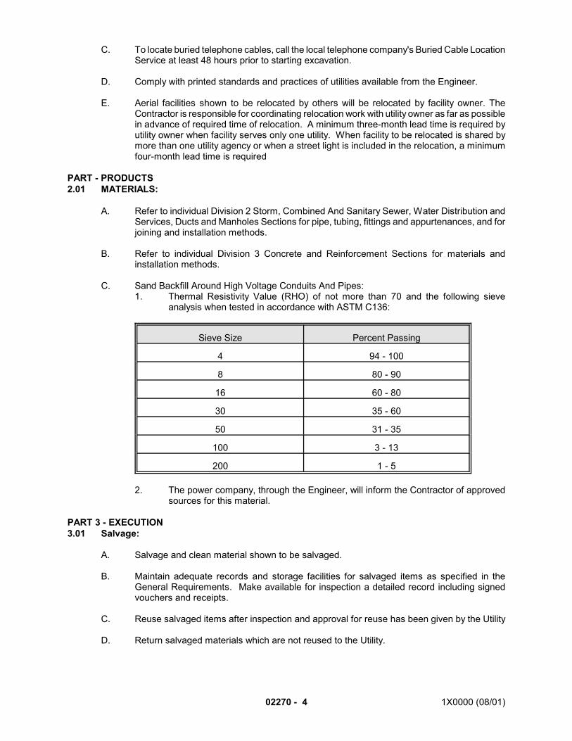
02270 - 4 1X0000 (08/01)
C. To locate buried telephone cables, call the local telephone company's Buried Cable LocationService at least 48 hours prior to starting excavation.
D. Comply with printed standards and practices of utilities available from the Engineer.
E. Aerial facilities shown to be relocated by others will be relocated by facility owner. TheContractor is responsible for coordinating relocation work with utility owner as far as possiblein advance of required time of relocation. A minimum three-month lead time is required byutility owner when facility serves only one utility. When facility to be relocated is shared bymore than one utility agency or when a street light is included in the relocation, a minimumfour-month lead time is required
PART - PRODUCTS2.01 MATERIALS:
A. Refer to individual Division 2 Storm, Combined And Sanitary Sewer, Water Distribution andServices, Ducts and Manholes Sections for pipe, tubing, fittings and appurtenances, and forjoining and installation methods.
B. Refer to individual Division 3 Concrete and Reinforcement Sections for materials andinstallation methods.
C. Sand Backfill Around High Voltage Conduits And Pipes:1. Thermal Resistivity Value (RHO) of not more than 70 and the following sieve
analysis when tested in accordance with ASTM C136:
Sieve Size Percent Passing
4 94 - 100
8 80 - 90
16 60 - 80
30 35 - 60
50 31 - 35
100 3 - 13
200 1 - 5
2. The power company, through the Engineer, will inform the Contractor of approvedsources for this material.
PART 3 - EXECUTION3.01 Salvage:
A. Salvage and clean material shown to be salvaged.
B. Maintain adequate records and storage facilities for salvaged items as specified in theGeneral Requirements. Make available for inspection a detailed record including signedvouchers and receipts.
C. Reuse salvaged items after inspection and approval for reuse has been given by the Utility
D. Return salvaged materials which are not reused to the Utility.
1X0000 (08/01) 02270 - 5
3.02 SETTLEMENT OR MOVEMENT:
A. Where settlement or movement monitoring system is shown, comply with the following:1. Provide series of settlement measurement points along each facility and make
regular readings to detect movements.2. Use approved painted marks, metal marker plugs or pins as settlement
measurement points.3. Prior to subsurface work, make initial survey to establish elevations of installed
settlement measurement points utilizing permanent, established bench marksoutside 100-foot line.
4. Take readings weekly on settlement points until completion of this Contract. Takereadings daily during work which may affect facilities.
5. Make readings to an accuracy of 0.01 foot.6. Take immediate remedial measures to correct conditions causing settlement or
other movement and to repair damages thus caused.
3.03 EXCAVATION AND BACKFILLING OF UTILITY TRENCHES:
A. Excavate and backfill utility facility trenches in accordance with Sections 02320, 02240 and02260.
B. Proceed with caution in areas of utility facilities; expose them by hand excavation or othermethods acceptable to facility owner.
3.04 SURFACE RESTORATION:
A. Remove pavements, sidewalks, lawns, landscaping , curbs and gutters where necessitatedby utility trenches in accordance with Section 02220.
B. Replace pavements, sidewalks, curbs and gutters in accordance with Section 02205.
C. Place temporary pavements where necessitated by sequence of operations.
D. Replace lawns and landscaping in accordance with Sections 02920 and 02930.
E. Provide erosion control measures to prevent erosion or displacement of soils and dischargeof sediment bearing water or airborne dust from the site.
3.05 UNSAFE AND UNSUITABLE UTILITY STRUCTURES:
A. General Requirements:1. If upon exposure, condition or location of facility to be supported in place is found to
be unsafe for maintenance or support, replace or reconstruct facility as required afterreceiving prior approval of the Engineer and Utility Owner.
2. Maintain continuity of existing utility facilities. Protect, support, relocate andreconstruct such facilities, regardless of jurisdictional control.
B. Electric, Communication and Similar Type Facilities:1. If structures containing electrical, communication and similar types of cables shown
to be maintained complete in place are found upon exposure to be incapable ofbeing maintained in place because of condition, location or both, replace suchstructures with timber enclosures or split ducts after prior approval of the Engineerand the utility owner.
2. When service box, manhole or conduit structure containing electrical orcommunication cables is broken away, replace it immediately with temporarystructure having facilities for racking and supporting cables equivalent to existingfacilities.
02270 - 6 1X0000 (08/01)
3. Exercise care when working in vicinity of telephone structures containing coaxialcable which cannot withstand movement.
4. Give timber enclosures one interior and one exterior coat of fire-retardant paint oftype specified by owners and operators.
5. Replace temporary timber enclosures with permanent structures in accordance withdetails shown and restore facilities to the satisfaction of the Engineer and utilitiesprior to completion of work. Remove materials of temporary nature after completionof permanent installation.
C. Procedures for payment of costs of work on unsafe and unsuitable utility structures aregoverned by the CHANGES article of the General Provisions.
END OF SECTION
1X000 (08/01) 02291 - 1
SECTION 02291
GEOTECHNICAL INSTRUMENTATION
PART 1 - GENERAL
1.01 DESCRIPTION:
A. This section specifies the design, installation, maintenance, and removal of geotechnicalinstrumentation to monitor soil, rock, and structure movements during construction. Thissection also includes specifications for reading, analyzing, and reporting instrumentationmonitoring results.
B. Design Criteria:1. Provide a system of geotechnical instrumentation which will allow monitoring of soil,
rock, and excavation support elements, as well as adjacent structures and utilitiesto ensure safety and stability, confirm design assumptions, and provide a basis forestablishing compliance with Contract requirements.
C. Definitions:1. Geotechnical Instrumentation - Any device designed to determine change in the
position or state of stress of soil, rock, and structures.2. Instrument Monitoring - The procurement of data obtained from the repeated optical,
mechanical, or electronic observations of geotechnical instruments.3. Frequency of Monitoring - The number of readings obtained from a geotechnical
instrument with respect to time.4. Initial reading- The first stable reading set obtained after instrument installation, but
prior to excavation, to which all subsequent readings will be compared.5. Threshold Limit Values Level 1 and Level 2 - Designer-specified limits for
geotechnical instrumentation which if exceeded require (1) notification of theAuthority and increased monitoring frequency and (2) implementation of thecontingency plan.
1.02 QUALITY ASSURANCE:
A. Comply with codes and regulations of the jurisdictional authorities.
B. Permits - Prior to instrumentation installation obtain any permits from the responsiblejurisdiction and pay permit costs and any associated fees at no additional cost to theAuthority.
C. Qualifications of Personnel:1. Instrumentation Selection, Design, Layout, and Data Analysis shall be performed by
a registered Professional Engineer specializing in geotechnical engineering with 5years experience in soil stability and geotechnical design
2. Instrumentation installation shall be performed under the supervision of qualifiedtechnicians with at least one year experience in the installation of instruments of thetype specified.
3. Instrumentation monitoring shall be performed by qualified technicians with at leastone year experience in the reading of instruments of the type specified.
D. Continuously maintain all geotechnical instrumentation in proper working condition and withinmanufacturer’s specifications. Immediately repair or replace malfunctioning equipment. Allinstrumentation readout devices to be periodically tested and recalibrated within schedule asrecommended by the instrument manufacturer or as approved by the Authority..
02291 - 2 (08/01) 1X0000
1.03 SUBMITTALS:
A. Submit the following for approval prior to proceeding with work:1. Type of instrumentation system proposed, showing arrangement, location and
depths of proposed system.2. Manufacturer’s literature including descriptions and installation recommendations for
all instruments, software, and read-out devices proposed for use.3. Instrumentation installation schedule and monitoring schedule.4. Resumes listing the qualifications of the Professional Engineer and Technicians
specified in 1.02.C.
B. Instrument Installation Data:1. Record of installation details including date and time of installation, general soil
condition at instrument site, adjacent construction activities, and remarks of unusualconditions observed during installation.
2. As-built location and elevation of installed instruments including coordinates anddistance referenced to Outbound track centerline. Supply location data within 48hours of instrument installation.
C. Instrumentation Monitoring Data:1. Analyzed data to be submitted on forms approved by the Authority within 48 hours
after instrument monitoring. Supply copies of field notes if requested.2. Immediately report to the Authority movements exceeding Level 1 limits.3. Shift Reports of Construction Activities:
a. For each shift in which work is taking place, submit a report within 24 hourscontaining the following:1) Detailed excavation and tunneling status at time of instrument
reading.2) Excavation subgrade elevation and tunnel face station at time of
instrument reading.3) Incidents of ground loss, groundwater flow, excavation support
instability, or any other unusual event.4) General construction activity in the vicinity of the instruments.5) Duration and cause of delays to construction activities.6) Weather conditions.
D. Contingency Plans:1. Submit contingency plans to stabilize soil, rock, and structures affected by adverse
movements detected by instrumentation. Submit contingency plans at least onemonth prior to start of excavation or tunneling. At a minimum, include the following:a. Names, telephone numbers, and locations of persons responsible for
implementation of contingency plans.b. Materials and equipment required to implement contingency plans.c. Location onsite of all required materials and equipment to implement
contingency plans.d. Step-by-step procedure for performing work involved in implementation of
the contingency plans.e. Threshold limit Level 1 and Level 2 values for all instruments.f. Clear identification of objectives of contingency plans and methods to
measure plan success.
1.04 JOB CONDITIONS:
A. Do not disclose to third parties or publish monitoring data without the approval of theAuthority.
1X000 (08/01) 02291 - 3
B. The Authority may monitor any geotechnical instrument at any time. Provide and facilitateaccess to instruments for the Authority.
C. The instrumentation monitoring data shall be continuously reviewed and interpreted by theresponsible instrumentation specialist.
D. During construction, additional instrumentation may be required beyond that proposed in theinitial design. Modifications to the instrumentation plan, including proposed instrumentlocations, may be required due to site conditions and instrumentation results.
E. Ensure that all instrumentation installations are continuously protected and are not damagedby construction activities, including blasting. Replace or repair as necessary any instrumentdamaged by construction activities or adverse soil, rock, or structure movement.
PART 2- PRODUCTS
2.01 INSTRUMENT TYPES:
A. Specify instrument types and locations in accordance with design criteria indicated in Section1.01 B.1. and as approved by the Authority.
PART 3 - EXECUTION
3.01 INSTRUMENT INSTALLATION SCHEDULE:
A. Install and obtain initial readings for all surface instrumentation prior to excavation, chemicalgrout operations, or dewatering activities, in accordance with approved schedule. In areasto receive chemical grout, delay installation of instruments which might be damaged bychemical grout until completion of this activity.
B. For all instrumentation located within excavated areas, install and obtain initial reading assoon as practical after excavation or passage of tunnel heading in accordance with approvedschedule.
3.02 INSTRUMENT LOCATIONS:
A. Install instruments as close as practical to locations submitted and approved. Actualconditions in field may require location adjustment. Obtain Authority approval for locationadjustments.
B. After instrument installation, submit reports showing location and installation details of eachinstrument as specified in Section 1.03.B.
C. Ensure that all proposed instrument locations will not result in damage to utilities or otherstructures. Coordinate proposed instrument locations with Miss Utility and any other affectedowners prior to instrument installation.
3.03 INSTRUMENTATION MONITORING:
A. Initial Reading:1. At time of initial reading, verify that instrument is functioning and has been installed
in accordance with contract specifications and manufacturer’s recommendations.2. Replace at no additional cost to the Authority any instrument which does not meet
specification requirements.

02291 - 4 (08/01) 1X0000
3. Obtain at least three separate and complete sets of initial readings on eachinstrument which yield consistent results.
4. Should inconsistent initial readings be obtained on any instrument, reread untilcorrect and repeatable readings are obtained.
B. Monitoring Frequency:1. Monitoring frequency to be in accordance with schedule submitted and approved as
specified in Section 1.3 A.3.2. Instrument readings which show significant change from previous readings shall be
reread immediately.
C. Instrumentation Monitoring Threshold Values:1. Instrumentation system design shall establish threshold limit values for each
instrument.a. Level 1 Limit values if exceeded require notification of the Authority within
24 hours and notification of individuals listed within the contingency plan.Monitoring frequency of affected instruments which exceed Level 1 limit willbe increased to frequency as approved within the contingency plan.
b. Level 2 limit values if exceeded require immediate notification of theAuthority and implementation of the contingency plan. Instruments whichexceed Level II limits will be monitored continuously until stability isachieved.
3.04 INSTRUMENT PROTECTION, MAINTENANCE, AND REPLACEMENT:
A. Protect and maintain instruments. Divert surface water from instrument covers. Flush debrisfrom instrument installations. Maintain access to all instruments.
B. Provide barriers as required to protect instrument.
C. Install and maintain instruments and instrument access covers in a manner which protectsworkers and ensures public safety.
D. Repair or replace damaged instruments within 5 days at no additional cost to the Authority.
3.05 REMOVAL OF INSTRUMENTS:
A. Prior to final acceptance of work and subject to Authority approval, remove and dispose ofall instrumentation.1. Remove surface instrument installations to 2 feet below ground surface. Backfill
voids and casing with cement grout.2. Restore ground surface to original condition.
B. Fill holes in masonry with portland cement mortar. Restore structure surfaces to originalcondition.
SEE ENDNOTES BELOW. THEY ARE AN ESSENTIAL PART OF THIS SECTION UNTIL EDITED BY THEDESIGNER.
ENDNOTES:
1. The Designer must specify the level 1 and 2 threshold values before finalizing thecontract-specific specifications.

1X000 (08/01) 02291 - 5
END OF SECTION
1X0000 (03/03) 02320 -1
SECTION 02320
GRADING, EXCAVATING AND BACKFILLING
PART 1 - GENERAL
1.01 DESCRIPTION:
A. This section specifies grading, excavating and backfilling for structures and utility facilities.
B. Related Work Specified Elsewhere:1. Removal of existing construction and facilities: Section 02220.2. Clearing and grubbing: Section 02230.3. Dewatering: Section 02240.4. Support of excavation: Section 02260.5. Underpinning, support and restoration of structures: Section 02255.6. Maintenance, support and restoration of utility facilities: Section 02270.7. Rock tunneling: Section 02410.8. Earth tunneling: Section 02415.9. Rock reinforcement: Section 02420.
C. Definitions:1. Grading: Shaping earth and rock through the removal or filling of earth and rock
materials.2. Earth Excavation: Excavation of materials of whatever nature, except rock as
defined below.3. Rock Excavation: Excavation of material in place which cannot be loosened or
broken down by ripping using earth excavating equipment and which requiresblasting or rock excavating equipment for its removal.
4. Approved Material: Earth which meets specified measurable requirements for useas embankment, fill or backfill.
5. Surplus Excavated Material: Approved excavated material which is not used inembankments or as fill on site.
6. Unsuitable Material: Material which does not meet specified requirements for usein situ or as embankment, fill or backfill and is prohibited for use in the work.
7. Authorized Excavation: Excavating to neat lines and limits shown and specified;excavating unsuitable material.
8. Unauthorized Excavation: Excavating materials which would otherwise be left inplace; excavation which is not specified as authorized excavation, such asexcavation beyond neat lines and bottoms of footings as shown.
9. Excess Excavation: Excavating materials beyond or below cross section shown, aswell as unavoidable over breakage in rock.
10. Controlled Low Strength Materials (CLSM): Fill.
B. Salvage:1. Materials shown to be salvaged in accordance with Section 02205 and the General
Requirements.
1.02 SUBMITTALS:
A. Submit the following for approval in accordance with the General Requirements and theadditional requirements as specified for each:1. Samples:
a. Submit sample 21 days in advance of desired date of approval. Two one-cubic-foot samples are required of each material proposed for fill, backfilland embankments.
02320 - 2 1X0000 (03/03)
b. Obtain, identify and ship soil and aggregate samples in accordance withASTM D75.
2. Documentation:a. Permits for disposal of excavated material:
1) Obtain written permits and releases from owners of property wherematerial will be deposited.
2) Each permit and release from each property owner will absolve theAuthority from responsibility in connection with such disposal of thematerial.
b. Blasting plan:1) Submit a blasting plan in accordance with Section 02410.
c. Plan for tunneling or jacking of utility facilities:1) Prior to tunneling, submit a tunneling plan.
(a) Include in the plan the location of the facility, the method ofconstruction, the types of equipment and the proceduresproposed.
(b) Procedure for field determination of soil bearing capacity,including description of the equipment to be used, and anycalibration curves for the various soil types to beencountered, details of field test procedures, forms forreporting of test data/results and details of minimumnumber of tests required for each footing/base area
3. Certification:a. With samples of materials proposed for fill, backfill and embankment,
submitcertified test reports of tests performed by an approved IndependentTesting Agency for all tests required to demonstrate compliance withspecified requirements.
1.03 QUALITY ASSURANCE:
A. Codes, Regulations, Reference Standards and Specifications:1. Comply with codes and regulations of the jurisdictional authorities.2. AASHTO: M147.3. ASTM: C33, D75 , D698, D2487, D2922, D3017, D4318.
1.04 JOB CONDITIONS:
B. Existing Drainage:1. Preserve, protect and maintain existing operable drains and sewers during grading
operations.2. Keep excavations dry.
C. Blasting:1. Control blasting in accordance with Section 02410.2. Exercise care in drilling and blasting operations so that the remaining rock remains
stable and overbreak is minimized. Use controlled blasting in areas where concretefor walls and arches of structures is to be placed against rock.
D. Accident Prevention and Safety:1. Perform work in accordance with specified safety requirements and PROTECTIVE
DEVICES article of the General Requirements.
E. Location of Underground Facilities and Structures:1. Locations shown for utility facilities are approximate.2. Utility facility locations and site investigations are listed in the General Requirements.3. Contact Miss Utility to have utilities located before beginning excavation.
1X0000 (03/03) 02320 -3
F. Toxic and Combustible Substances:1. During excavation, provide detection and testing equipment and carry out necessary
tests to detect the presence of toxic and combustible substances.2. Take action to safeguard persons and property in accordance with the rules and
regulations of the jurisdictional agencies and utility owners.3. Promptly notify utility owners when problems concerning their facilities become
apparent.
G. Ramps:1. Construct temporary ramps as necessary to provide access to work area.2. Locate such access ramps in Contractor's storage, operations and access areas or
within excavation for subway structure and maintain traffic as specified.3. Support ramp excavation in accordance with Section 02260.4. When ramps are in use, station flag persons equipped with red flags at ramp
entrances to keep unauthorized vehicles or persons from entering work area.5. When work necessitating entrance or exit of vehicles via ramps is not being
performed, protect entrances and exits of ramps by warning signs, barricades andfences in accordance with the General Requirements.
6. Upon completion of the work needing ramps, remove the ramps in accordance withSection 02260; backfill excavated ramp areas, if necessary.
H. Excavation Near Buildings:1. Control excavation in areas near buildings or structures to maintain stability of
buildings or structures. If underpinning is necessary, perform excavation work inaccordance with Section 02255, so that condition of surrounding area remainsunimpaired.
PART 2 - PRODUCTS:
2.01 MATERIALS:
A. Embankment, Fill or Backfill Materials:1. Composition:
a. Well-graded soil-aggregate mixture, as defined by ASTM D2487, comprisedof stone, gravel, sand, silt, clay or combinations of such materials.
b. Prohibited material: Organic matter, debris, cinders and frozen material.2. Additional requirements:
a. Particle size: Four inches maximum, but not exceeding one inch within onefoot of finished grade.
b. Liquid limit: Forty maximum, determined in accordance with ASTM D4318.c. Plasticity index: Ten maximum, determined in accordance with ASTM
D4318.d. Maximum dry density: Not less than 100 pounds per cubic foot.
B. Select Material: AASHTO M147, with the following gradation requirements:
THIS SPACE NOT USED.
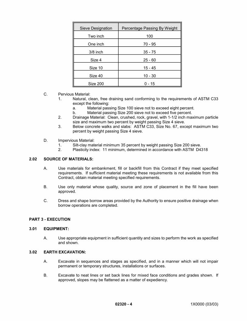
02320 - 4 1X0000 (03/03)
Sieve Designation Percentage Passing By Weight
Two inch 100
One inch 70 - 95
3/8 inch 35 - 75
Size 4 25 - 60
Size 10 15 - 45
Size 40 10 - 30
Size 200 0 - 15
C. Pervious Material:1. Natural, clean, free draining sand conforming to the requirements of ASTM C33
except the following:a. Material passing Size 100 sieve not to exceed eight percent.b. Material passing Size 200 sieve not to exceed five percent.
2. Drainage Material: Clean, crushed, rock, gravel, with 1-1/2 inch maximum particlesize and maximum two percent by weight passing Size 4 sieve.
3. Below concrete walks and slabs: ASTM C33, Size No. 67, except maximum twopercent by weight passing Size 4 sieve.
D. Impervious Material:1. Silt-clay material minimum 35 percent by weight passing Size 200 sieve.2. Plasticity index: 11 minimum, determined in accordance with ASTM D4318
2.02 SOURCE OF MATERIALS:
A. Use materials for embankment, fill or backfill from this Contract if they meet specifiedrequirements. If sufficient material meeting these requirements is not available from thisContract, obtain material meeting specified requirements.
B. Use only material whose quality, source and zone of placement in the fill have beenapproved.
C. Dress and shape borrow areas provided by the Authority to ensure positive drainage whenborrow operations are completed.
PART 3 - EXECUTION
3.01 EQUIPMENT:
A. Use appropriate equipment in sufficient quantity and sizes to perform the work as specifiedand shown.
3.02 EARTH EXCAVATION:
A. Excavate in sequences and stages as specified, and in a manner which will not impairpermanent or temporary structures, installations or surfaces.
B. Excavate to neat lines or set back lines for mixed face conditions and grades shown. Ifapproved, slopes may be flattened as a matter of expediency.
1X0000 (03/03) 02320 -5
C. Support sides of excavation as specified in Section 02260.
D. Protect, support and maintain utility facilities as specified in Section 02270.
E. Proceed with caution in areas of utility facilities; expose them by hand excavation or othermethods acceptable to the facility owner.
F. Control runoff so that water does not run through excavation area. Keep excavation free ofwater.
G. Remove excavated materials to fill, embankment, stockpile or disposal locations. Keep haulroutes clean in accordance with the General Requirements.
H. Fill excess excavations with approved materials and compact as specified.
I. Unauthorized excavation for the purpose of obtaining materials for resale or for use atanother job site is prohibited unless otherwise approved by the Engineer.
3.03 ROCK EXCAVATION:
A. Perform rock excavation to neat lines shown and so as to produce surfaces free of looserock.
B. Install rock reinforcement in accordance with Section 02420.
C. Remove loose, semi-detached and unsound fragments from blasted surfaces. Removestanding water, debris, oil and other objectionable coatings from surfaces of rock upon oragainst which concrete or porous fill material is to be placed.
D. Repair shattered or loosened rock surfaces outside neat lines shown, which in the opinionof the Engineer would be detrimental to subway structure or would adversely affect subwaydrainage system.
E. Where directed, grout rock surfaces which have not been shattered but are naturallypermeable.
F. Remove excavated rock to approved fill locations or disposal locations.
G. Fill excess excavation with concrete or other approved material.
H. If flowing or seeping water is encountered during excavation, install approved drainagesystem in accordance with Section 02240.
3.04 REMOVAL OF SUBSURFACE OBSTRUCTIONS:
A. Permanent Closure walls:
B. Prior to removal of parts of vaults or areaways which extend into Contract limits, buildpermanent closure walls where shown in such vaults or areaways to separate areas to beleft intact from areas to be removed.1. Obtain the Engineer’s approval of permanent closure wall design prior to its
installation.
C. Remove vaults, areaways and foundation walls as shown.
3.05 EMBANKMENT, FILL AND BACKFILL:
02320 - 6 1X0000 (03/03)
A. Place embankment, fill and backfill in eight-inch loose layers, unless otherwise shown, forentire width so that each layer can be uniformly and properly compacted.
B. Avoid accumulation of large pieces of material at one location. Fill voids and interstices withfiner materials.
C. In confined areas, use approved power-actuated compactors to achieve required density.
D. Prior to compaction, adjust moisture content of material within required limits by drying orwatering either at material source or on fill.
E. Leave struts, braces, lagging and timber sheathing in place as long as needed to supportexcavation and adjacent facilities and structures.
F. Where utility facilities and structures are supported in place, use special equipment andtechniques as required to achieve specified compaction under and around them.
G. Do not place backfill on subway structures until requirements for curing and waterproofinghave been complied with and, if required, until test cylinders for particular structure indicatethat concrete has attained specified compressive strength.
H. When backfilling against structures, place material approximately simultaneously on bothsides of structures to equalize opposing horizontal pressures.
I. When backfilling on tops of structures, place material in six-inch lifts over full area.
J. Under concrete floor and other slabs on grade, place drainage material directly on preparedsubgrade which meets density and elevation requirements. Compact with hand-operatedplate-type vibratory compactor.
K. Prior to placing embankment against slope greater than one vertical to four horizontal, cutbenches into existing slope. Height of bench not to exceed two feet unless otherwiseapproved.
L. Maintain embankment, fill and backfill in stable, well-drained condition.
M. Where approved, dispose of surplus excavated material by widening embankments andflattening slopes.
N. Where pervious material will be exposed to erosion, cover it with 12-inch layer of approvedimpervious material compacted in place.
3.06 COMPACTION ADJACENT TO STRUCTURES:
A. Compact embankment, fill or backfill materials within five feet of retaining walls, abutmentsor other structures using lightweight compactors.
B. Do not overstress structures.
C. Backfilling against new structures without approval is prohibited.
3.07 EXCAVATION OF UNSUITABLE MATERIALS:
A. Remove unsuitable materials from the site.
B. Replace unsuitable material with approved material and compact as specified.
1X0000 (08/01) 02320 - 7
3.08 PREPARATION OF GROUND AS SUBGRADE:
A. Where the subgrade is on original ground or in cut or where embankment or fill is less thanone foot, fulfill compaction requirement for 12 inches minimum below final subgrade.
B. If necessary, scarify original ground and adjust moisture content prior to compacting.
3.09 FIELD QUALITY CONTROL:
A. Allowable Tolerances:1. Construct finished subgrade to vary not more than 0.05-foot above or 0.10-foot
below elevation shown.2. Complete embankment slopes to plus-or-minus 0.5 foot of slope line shown.3. Maintain moisture content of embankment, fill or backfill material within plus-or-
minus three percent of optimum moisture content of material.4. Compact each layer of embankment, fill or backfill to 95 percent of maximum dry
density as determined in accordance with ASTM D698, at moisture content withintolerance specified, except the following:a. From upper surface of fill or backfill to a plane 12 inches below subbase
level of vehicular pavement, sidewalks, trackbeds and structural foundationsto 100 percent of maximum dry density at moisture content within tolerancespecified.
b. In areas of 95-percent compaction where utility facilities are located in filland are not supported on concrete cradles, compact material for a depth ofone foot directly below bottom of facility to 100 percent of maximum drydensity at moisture content within tolerance specified.
B. Test Method:1. Determine the maximum dry density and the optimum moisture content in
accordance with ASTM D698.2. Determine in-place density and moisture content in accordance with ASTMD2922
and ASTM D3017 respectively, or other test methods acceptable to the Engineer.
3.10 TUNNELING FOR OR JACKING OF UTILITY FACILITIES:A. Location of facility, method of construction, type of equipment and procedures: As approved.
3.11 FINISHING:
A. On completion of work, clean ditches and channels.
B. Slope and shape borrow areas to provide positive drainage.
C. Remove unsuitable and surplus excavated materials to locations outside the Authority's right-of-way.
D. Leave site in neat, presentable condition.
END OF SECTION
1X0000 (03/03) 02410 - 1
SECTION 02410
ROCK TUNNELING
PART 1 - GENERAL
1.01 DESCRIPTION:
A. This section specifies the following:1. Rock tunneling for running sections, stations, pilot drifts through stations, side drifts,
crossover and transition sections, vaults, adits, auxiliary tunnels, escalator ways andcross-passages.
2. Tunnel linings.
B. Related Work Specified Elsewhere:1. Grading, excavating and backfilling: Section 02320.2. Dewatering: Section 02240.3. Subway drainage system: Section 02625.4. Earth tunneling: Section 02415.5. Rock reinforcement: Section 02420.6. Drilling and pressure grouting for rock tunnels: Section 02431.7. NATM excavation (rock): Section 02411.8. Concrete work: Sections 03100, 03200 and 03300.9. Shotcrete: Section 03370.10. Structural steel: Section 05120.11. Epoxy injection: Section 07125.12. Bentonite slurry: Section 07170.13. Piping systems: Section 15205. *1
C. Definitions:1. Rock tunneling: Excavation of natural rock, which requires use of rock excavation
methods, such as drilling and blasting, channeling, wedging or barring, or rocktunneling machines.
2. Controlled blasting: Excavation of rock in which the various elements of the blast,i.e., hole size, depth, spacing, burden, charge size, distribution, delay sequence, arecarefully balanced and controlled to provide a distribution of charge which willexcavate rock to required contours with smooth surface to minimize overbreak,stressing and fracturing of the rock beyond the contour line. Smooth-wall blasting,presplitting, cushion blasting and line drilling are examples of operations included inthe term controlled blasting.
3. Initial support:a. Elements designed, furnished and installed by the Contractor for stability
and safety during construction and not shown.b. To the extent elements of permanent lining shown are effective in providing
initial support, such elements may be utilized to provide initial support. Ifpermanent lining must be augmented by initial support to ensure stabilityand safety during construction, provide elements of such initial support.
c. Elements of initial support may be in the form of additional rock bolts,shotcrete, plain concrete, reinforced concrete, timber or steel memberswhich may be temporary or permanent if compatible with permanent liningshown. Plain or reinforced concrete may consist of elements such as wallgirders, carrier beams or supplementary foot blocks for temporary posting.Timber may consist of elements such as posts, struts and cross beams.Steel members may consist of such elements as steel sets, straps, spiling,
02410 - 2 1X0000 (03/03)
crown bars, carrier beams, girders, brackets, posts, struts, shores or needlebeams. Design and provide these or other alternative elements, singly orin combination, to ensure stability and safety during construction. Installinitial support to transfer loads to rock so as to ensure stability and safetyduring construction.
4. Permanent lining: Tunnel lining elements and support as shown.
1.02 QUALITY ASSURANCE:
A. Codes, Regulations, Reference Standards and Specifications:1. Comply with codes and regulations of the jurisdictional authorities.2. Appendix G of the General Requirements: Geotechnical Design Report.3. MS: MIL-P-26915 (USAF).4. ASTM: C171, D638, D1304. *25. ASTM: C171, D638, D1304, D1785, D2464, D2564. *3
B. Blasting Consultant:1. Engage the services of approved, qualified independent, professional blasting
consultant to design, review, evaluate and modify blasting operations.
C. Allowable Tolerances:1. Steel rib bending tolerance:
a. Conformance to true template:1) Wide-flange sections up to 14 inches deep weighing 150 pounds
per foot: Rib segments to conform to true template at butt plates;intermediate points may depart from true template up to 3/8 inch,providing no point departs more than 1/8 inch from three-foottemplate section.
2) Wide flange sections heavier than 150 pounds per foot:Intermediate departure not exceeding 5/8 inch from true template;deviation from three-foot template section not exceeding 3/16 inch.
b. Bending curvature uniform.c. After bending:
1) Outer flange will be permitted to droop 1/8-inch maximum towardinner flange for radii of bend equal to or greater than 14 times ribdepth; 1/4-inch maximum droop will be permitted for radii of bendwhich are less than 14 times rib depth.
2) Rib depth at not less than theoretical depth minus 1/4 inch.2. Steel rib fabrication tolerances:
a. Chord, out-to-out of butt, foot plates or both measured on centerline of rib:Theoretical length plus-or-minus 1/16 inch.
b. Face of butt or foot plates: Within plus-or-minus 1/16 inch of theoreticalplane.
c. Gap between ends of ribs and butt or foot plates prior to welding notexceeding 1/16 inch for at least 75 percent of cross sectional area of rib.Where gaps are in excess of 1/16 inch, fill by additional steel-shim welding.
d. Tie rod holes in rib webs: Within plus-or-minus 3/8 inch of locations shownon approved shop drawings.
e. Width or length of sheared plates: Within theoretical dimension plus-or-minus 1/8 inch.
f. Center-to-center of bolt hole dimensions on butt or splice plates:Theoretical dimension plus-or-minus 3/64 inch.
1X0000 (03/03) 02410 - 3
g. Bolt hole groups in butt or splice plates after fabrication: Within plus-or-minus 1/16 inch of theoretical location regardless of variations in ribresulting from other tolerances.
h. Holes in butt plates welded to ribs: Within plus-or-minus 1/16 inch oftheoretical location.
3. Precast-concrete segment tolerances: As shown.4. Watertightness criteria: Section 03300.
1.03 SUBMITTALS:
A. Submit the following for approval in accordance with the General Requirements and with theadditional requirements as specified for each:1. Working Drawings:
a. Prior to using tunneling machines, submit drawings showing design,specification, method of operation and other pertinent data.1) Drawings and pertinent data for shielded tunnel-boring machine
(TBM). Show dust-suppression system. If precast-concrete tunnel-lining segments are used, show the following:(a) That machine can develop forward thrust independently of
installed precast-concrete tunnel lining, if this lining is to beused.
(b) That machine is equipped to handle and erect precast-concrete segments behind cutter head within tail shield,including auxiliary equipment necessary for erection.
(c) Descriptions, data or calculations of proposed facilities,equipment to be utilized and method of construction. Itemsinclude, but are not limited to, the following: Hoisting plant,tunnel ventilation, lighting and drainage; groundwater-control methods; temporary shafts, cuts, ramps andtunnels; breakouts; cross passages; bulkheads; details ofinitial support; details of placing concrete and erectionprocedures for the installation of precast-concrete tunnellining.
b. For excavation of tunnels and stations, submit drawings, calculations,descriptions and specifications for the following:1) Number, size, location, orientation and direction of excavation of
drifts and benches including those excavated previously andtemporary drifts.
2) Sequence and timing of excavating drifts and benches includingstagger of advance of heading in adjacent drifts or benches andanticipated rate of advance.
3) Blasting program including length of round and charge distributionfor each drift.
4) Initial support elements, including when and where they will beinstalled in relation to excavation plan and sequence and designcalculation and assumptions.
5) Permanent lining elements relationship to initial support elementsand to the plan and sequence of excavation and support.
6) Construction equipment and capacities.7) Assumptions used in arriving at above items, including:
(a) Thickness and condition of various zones of rock,decomposed rock and overburden.
(b) Incidence, orientation and extent of rock discontinuitiesincluding foliation, joints, shears, fractures, faulting, folding,
02410 - 4 1X0000 (03/03)
depth and degree of weathering, condition of discontinuities(open, tightly closed, gouge-filled).
(c) Relationship of excavation and initial support to rockdiscontinuities.
(d) Design load conditions and design mechanical propertiesof rock and discontinuities used for determining initialsupport requirements.
(e) Stability of sidewall and vertical rock faces with respect toexcavation dimensions, sequence and rock discontinuities.
(f) Groundwater.2. Certification:
a. Certified test report of properties of electrical insulative coating.3. Documentation:
a. Blasting plan:1) Not less than 30 days prior to starting a new phase of work, submit
the following data concerning proposed blasting operations:2) Location, depth, area, anticipated neat lines and relationship to
adjacent excavations and structures.3) Diameter, spacing, burden, depth, pattern and inclination of blast
holes.4) Type, strength, amount in terms of weight and cartridges of
explosives to be used in each hole, on each delay and total for eachblast.
5) Distribution of charge in each hole and priming of each hole.6) Type, sequence and number of delays, delay pattern; wiring
diagram for blast; size and type of hookup lines, and lead lines; typeand capacity of firing source; type, size and location of safetyswitches, lightning gaps.
7) Scaled range or distance used to calculate scaled range if blast willexceed vibration limits.
8) Stemming of holes and matting or covering of blast area. 9) Qualifications of person directly responsible for supervising loading
of shot and for firing it.10) Complete, maintain and submit permanent blast reports including
logs of each blast. Complete reports after each blast to include thefollowing:(a) Date, time and limits of blast by station.(b) Amount of explosives used by weight and number of
cartridges.(c) Total number of delays used and number of holes used for
each delay period.(d) On a diagram of approved blast pattern indicate each hole
not drilled, drilled but not loaded, changes in spacing or inpattern of delays or in loading of holes.
(e) Total number of holes, maximum charge per hole andcorresponding delay number.
(f) Evaluation of blast indicating tights, areas of significantoverbreak and recommended adjustments for next blast.
b. Permits for disposal of excavated material:1) Arrange for disposal of excavated materials at locations outside the
Authority's right-of-way, and obtain written permits from owners ofproperty where excavated material will be deposited.
1X0000 (03/03) 02410 - 5
2) Submit each permit and release from each property ownerabsolving the Authority from responsibility in connection withdisposal of such material.
3) Details of temporary ventilation:4) In the event it is planned to use equipment not covered by the
SAFETY REQUIREMENTS article of the General Requirements,submit details of such equipment.
5) Approval of the use of alternative equipment will depend onsubmitted research information concerning performance inaccordance with applicable standards in common use.
a. Air-quality reports:b. Daily reports of tests for dust, toxic and hazardous gases and other
atmospheric impurities in the working environment during construction.c. Leak repair work plan:
1) Include proposed application methods, equipment details andschedule, as well as complete manufacturer's literature, data,instructions and recommendations.
2) Submit prior to beginning leak repair work.
PART 2 - PRODUCTS
2.01 MATERIALS:
A. Formwork: Section 03100.
B. Reinforcing Steel: Section 03200.
C. Concrete: Section 03300, Class 3500; Class 2500 concrete backfill where specified for rocktrench for track drain.
D. Contact Grouting: Section 02431.
E. Structural Steel, Ribs, Beams, Channels and Plates: Section 05120.
F. Bolts: ASTM A325, unless otherwise shown or specified.
G. Timber for Blocking, Lagging, Foot Blocks and Cribbing: Sound, well-seasoned, hardwoodtimber of rectangular cross section.
H. Track Drainage: Section 02625.
I. Porous Subgrade Material: Section 02625.
J. Pea Gravel: Smooth, rounded pieces of gravel, clean and free from objectionable materialssuch as soft particles, coal and lignite particles or friable particles, graded from 1/4 to 3/8 inchin size.
K. Sand: Section 03300, fine aggregate, except 100-percent passing U.S. Standard Sieve Size16.
L. Precast Concrete Tunnel Lining Segments: Section 02425.
M. Impervious Membrane: Polyethylene, ASTM C171, clear or opaque, 0.006-inch thickness.
02410 - 6 1X0000 (03/03)
N. Epoxy Injection Material: Section 07125.
O. Bentonite Slurry for Repair of Leaks: Section 07170.
P. Epoxy Mortar:1. Two-component, solventless epoxy-resin system, with 100-percent solids, workable
in temperature range of 50F to 60F when mixed with sand in specified proportions.2. Epoxy-resin system: FX-775, Fox Industries, Incorporated; Sikadur 31, Hi-Mod Gel,
Sika Chemical Corporation or approved equal.3. Sand for use with epoxy resin: Three parts No. 16 sand to one part No. 90 sand.
High-silica type, dry and bagged.4. Add sand to epoxy paste as necessary to provide best workability characteristics up
to one part sand per one part epoxy.
Q. Electrical Insulative Coating: Approved moisture-insensitive coating, 100-percent solids,containing no solvents for use on dry or damp concrete or steel surfaces, with the followingadditional requirements:1. Properties:
a. Minimum tensile strength: ASTM D638, 5,000 psi in 14 days.b. Dielectric strength: ASTM D1304, 440-465 volts per mil.c. Dielectric constant: ASTM D1304 as follows:
1) 60 Hertz: 3.4-3.5.2) 1,000 Hertz: 3.3-3.4.
d. Power factor: ASTM D1304 as follows:1) 60 Hertz: 0.006-0.007.2) 1,000 Hertz: 0.03-0.04.
e. Viscosity: 6,000 centipoises plus-or-minus 1,000 centipoises, asdetermined by Brookfield Viscometer using No. 6 spindle at 50 rpm.
2. Primer: Zinc-rich primer, MS MIL-P-26915 (USAF) Type 1, Class B.
R. Hydrostatic-Pressure Relief System: *41. Plastic pipe: PVC, Schedule 40, ASTM D1785.2. Plastic fittings: PVC, Schedule 40, ASTM D2464.3. Solvent cement: ASTM D2564.4. Galvanized steel pipe and fittings: Section 15205.
2.02 FABRICATION:
A. Fabricate steel supports in accordance with Section 05120.
B. The following operations are not required:1. Portions of bearing members such as butt and foot plates, straightened, planed and
connected after fabrication.2. Grinding to remove nicks resulting from flame-cutting.3. Planing and facing of sheared edges or bearing surfaces.4. Subpunching or subdrilling of bolt holes.5. Inspection of groove and fillet welds by other than visual inspection.
PART 3 - EXECUTION
3.01 TEMPORARY VENTILATION:A. Provide, operate and maintain for duration of project temporary ventilation system which
conforms to specified safety requirements and those of jurisdictional authorities. Removesystem from site when work is completed.
1X0000 (03/03) 02410 - 7
3.02 SAFETY REQUIREMENTS:
A. Perform work so as to minimize safety hazards and exposure of men and equipment tohazardous and potentially hazardous conditions in accordance with specified safetyrequirements.
B. In case of emergency or work stoppage likely to endanger excavation or adjacent structures,continuously maintain full work force 24 hours per day including weekends and holidays untilemergency or hazardous conditions no longer jeopardize stability and safety of the work.
3.03 DISTANCE BETWEEN HEADINGS:
A. Maintain longitudinal distance of no less than 150 feet between two adjacent tunnel facesbeing simultaneously excavated unless otherwise shown or approved in writing.
B. Where tunnel heading is being advanced adjacent to previously excavated tunnel, ensurethat initial support in first tunnel is completely installed and is adequate to withstandconstruction of second tunnel.
3.04 DETECTION OF MOVEMENT:
A. In accordance with the General Requirements and as shown, install, maintain and makeobservations of a system of detection of vertical and horizontal movement of ground, tunnelsupport, permanent lining and utilities adjacent to the work.
B. Special Instruments:1. Provide instrumentation as specified and where shown.2. Provide such facilities as directed for monitoring these instruments and take
appropriate action to arrest movement revealed by resulting observations.
3.05 FIELD QUALITY CONTROL:
A. Allowable Tolerances:1. Excavate to accommodate tunnel cross section and minimum thickness of lining
selected to within one inch of alignment and grade shown.2. When steel ribs are used for initial support, do not permit any portion of lagging
except clips or bolts used to attach lagging to ribs to extend into tunnel withinconcrete design line as shown nor any portion of steel rib including bracing to extendfurther than three inches into concrete design line.
3. Place cast-in-place tunnel concrete to the following tolerances:a. Tunnel lining:
1) Departure of tunnel from line or grade shown as measured fromworking point of tunnel: One inch.
2) Variation in thickness of lining at any point: Minus zero inch.3) Variation in internal diameter at any point: One inch.
b. Invert: As specified in Section 03300.c. Safety walk: As specified in Section 03300.
4. Install precast concrete segment lining to tolerances shown.
3.06 EXCAVATION:
A. Excavate to lines, grades, dimensions and tolerances as shown and specified toaccommodate initial support and permanent lining.
02410 - 8 1X0000 (03/03)
B. Tunneling Machine:1. When excavating with tunneling machine, use equipment which includes dust-control
system with spray system and dust shroud. Keep intake end of fan suction line asclose to machine as possible without interfering with other operations.
2. Use equipment which permits installation of initial support no further than ten feetfrom tail. Use hood if necessary. Install initial support in accordance with approvedworking drawings.
3. In order to exercise option for using circular permanent lining comprised of precastsegments, excavate tunnel and erect the segments by means of TBM. If, duringmachine boring, material is encountered in reaches of tunnel that cannot beexcavated satisfactorily by TBM, excavate such reaches by other approved methods.Provide necessary initial support and cast-in-place concrete permanent lining asshown for such conditions.
C. Air Quality:1. Perform drilling and tunneling operations by methods and with equipment which will
positively control dust, fumes, vapors, gases, fibers, fogs, mists or other atmosphericimpurities in accordance with specified safety requirements.
2. Provide approved instruments for testing quality of tunnel atmosphere; take samplesunder working conditions at prescribed intervals. Submit results of the quality tests.
D. Drilling and Blasting:1. Perform blasting in accordance with the General Requirements and approved
blasting plan.2. Have the blasting consultant design initial blasts as well as supervise and conduct
test blasts, if required, until regular production controlled blast patterns aredeveloped that produce desired rate of excavation while meeting requirements forvibration and air-blast control. Have consultant periodically, or when requested bythe Engineer, review blasting operations and direct such changes in blastingoperations as necessary to produce a controlled blasting operation meeting specifiedrequirements.a. Before blasting within 50 feet of cured concrete, except shotcrete, submit
and obtain approval of plan showing relative positions of concrete, area tobe blasted and blasting technique to be employed.
b. Protect concrete work and structures in vicinity of blasting by limiting size ofblasts, by covering blasts and by other means until it is certain that there isno danger of damage by shock waves or flying rock.
c. Use controlled blasting techniques. Modify blasting round as necessary toachieve best obtainable results and to keep vibrations and noise within limitsspecified.
d. As excavation proceeds and immediately after each blast, test the roofs andwalls; scale loose and shattered rock which is likely to fall. Carry out similarchecks on previously excavated sections at least every 48 hours; rechecksupport system and tighten, lagging, blocking and rock bolts as necessary.
e. When so directed, drill feeler or pilot holes no less than 1-1/2 inch diameterahead of excavation to predetermine nature and condition of materials to beexcavated. Number of holes, location, direction and length, minimum 15feet and maximum 30 feet: As directed.
f. Install initial support in accordance with approved working drawings.
E. Vibration and Air-Blast Control:1. Control operations in accordance with the following:
a. Peak particle velocity:
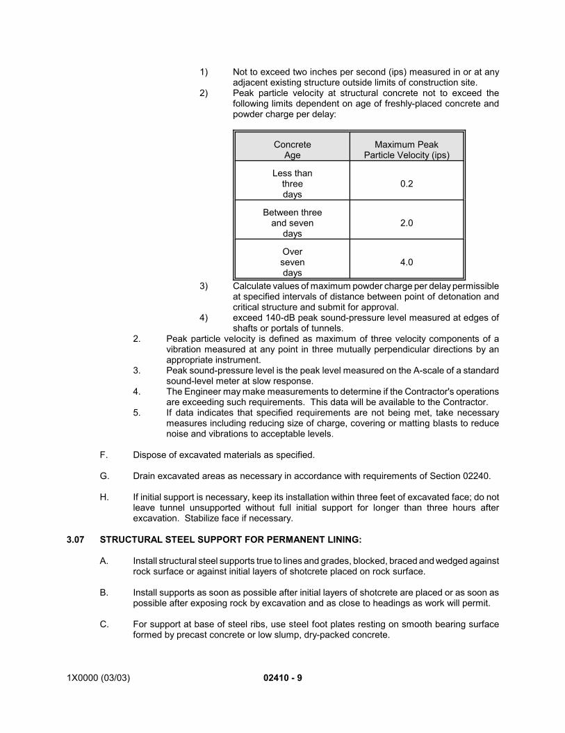
1X0000 (03/03) 02410 - 9
1) Not to exceed two inches per second (ips) measured in or at anyadjacent existing structure outside limits of construction site.
2) Peak particle velocity at structural concrete not to exceed thefollowing limits dependent on age of freshly-placed concrete andpowder charge per delay:
ConcreteAge
Maximum PeakParticle Velocity (ips)
Less thanthreedays
0.2
Between threeand seven
days2.0
Oversevendays
4.0
3) Calculate values of maximum powder charge per delay permissibleat specified intervals of distance between point of detonation andcritical structure and submit for approval.
4) exceed 140-dB peak sound-pressure level measured at edges ofshafts or portals of tunnels.
2. Peak particle velocity is defined as maximum of three velocity components of avibration measured at any point in three mutually perpendicular directions by anappropriate instrument.
3. Peak sound-pressure level is the peak level measured on the A-scale of a standardsound-level meter at slow response.
4. The Engineer may make measurements to determine if the Contractor's operationsare exceeding such requirements. This data will be available to the Contractor.
5. If data indicates that specified requirements are not being met, take necessarymeasures including reducing size of charge, covering or matting blasts to reducenoise and vibrations to acceptable levels.
F. Dispose of excavated materials as specified.
G. Drain excavated areas as necessary in accordance with requirements of Section 02240.
H. If initial support is necessary, keep its installation within three feet of excavated face; do notleave tunnel unsupported without full initial support for longer than three hours afterexcavation. Stabilize face if necessary.
3.07 STRUCTURAL STEEL SUPPORT FOR PERMANENT LINING:
A. Install structural steel supports true to lines and grades, blocked, braced and wedged againstrock surface or against initial layers of shotcrete placed on rock surface.
B. Install supports as soon as possible after initial layers of shotcrete are placed or as soon aspossible after exposing rock by excavation and as close to headings as work will permit.
C. For support at base of steel ribs, use steel foot plates resting on smooth bearing surfaceformed by precast concrete or low slump, dry-packed concrete.
02410 - 10 1X0000 (03/03)
D. Position joints to facilitate steel-rib installation as necessary and as approved.
E. Wedge and brace blocking and cribbing solidly between rock surface or initial shotcrete layerand steel supports. Check blocking and cribbing and retighten after every blast or morefrequently as necessary to maintain it in a secure condition.
F. Use no greater amount of wedging, blocking, timber lagging and cribbing than necessary tosupport ground safely and to distribute load to structural-steel supports.
G. Do not cover more than 25 percent of rock surface abovespring line with wedging, blocking,timber lagging and cribbing nor more than 25 percent of projected rock surface of walls belowspring line. 25-percent criterion applies along any 10 feet of horizontal undergroundexcavation and between any two adjacent steel ribs placed less than 10 feet on center.
H. Limit spacing of blocking and wedging points on outside flange of steel set to 48 inchesmaximum, unless otherwise shown.
I. Steel lagging may be used in any amount in any underground excavation providing it permitsready placement of shotcrete and flow of concrete around it.
J. Place wedging, blocking, lagging and cribbing in an open arrangement to permit readyplacement of shotcrete and flow of concrete through and around them.
K. Repair or replace structural steel supports placed improperly or damaged.
3.08 PERMANENT LINING:
A. Cast-In-Place Concrete:1. Invert:
a. Prior to installing drainage system and constructing invert slab, clean offloose material.
b. Install drainage pipes and place porous subgrade material as shown and inaccordance with Section 02625.
c. Place impervious membrane over subgrade layer and extend it continuouslyup sides of invert and above top of expansion-joint material, taking care toprevent puncturing and tearing it. Tape laps and repair tears or puncturesin membrane with material recommended by membrane manufacturer.
2. Permanent lining: In accordance with Sections 03100, 03200 and 03300 and asfollows:a. Prior to placement of concrete, remove timber blocks or wedges extending
into concrete design line by such means as to not endanger stability ofsurrounding ground.
b. Place concrete for lining upper portion of tunnel by mechanical or pneumaticmethods through pipes which discharge as nearly as practicable to highestpoint of structure. Do not use pneumatic equipment with high-velocitydelivery, unless it has velocity-discharge control and unless its dischargeline is continuously embedded at least four feet in fresh concrete
c. Fill spaces around posts, ribs and lagging beyond limits of concrete lining.Use concrete, grout or mortar as best suited to conditions at particularlocations.
d. Fill enlargements of tunnel excavation beyond dimensions shown withconcrete or grouted prepacking.
e. Force concrete into contact with lagging and ribs
1X0000 (03/03) 02410 - 11
f. After concrete has attained its design strength, perform contact grouting tofill voids in accordance with Section 02431.
g. For sections in which permanent lining includes steel ribs, comply withsequence of operations and details shown.
h. Starter walls:1) Construction of starter walls, 18 inches minimum height, permitted
as separate pour after supporting concrete has attained strength tosupport starter wall forms.
i. Tolerances for cast-in-place permanent tunnel lining are based on designalignment, not on actual alignment. Locate initial support with sufficientallowance for permanent lining without violating clearance requirements.
B. Precast-Concrete Tunnel Lining:1. Install tunnel lining so as to prevent damage to lining and coating. Use taper rings
on curves.2. When installing segments ensure that edges are clean and free from materials that
could interfere with proper bearing of segments.3. Place invert segment over properly shaped bed of pea gravel providing full and even
bearing.4. Alternate erection of side segments to prevent shifting of invert segment.5. Erect precast-concrete segments immediately behind tunneling-machine cutter head
and inside tail shield of TBM. 6. Complete ring of precast-concrete segments, without dislodging or damaging gasket.
Lubricate gasket of last segment of each ring prior to its installation.7. Backpack solidly each completed ring of precast-concrete segments with pea gravel
and grout. Place pea gravel so as to ensure complete filling of space between liningand excavated surface of tunnel. Do not install more than two completed ringswithout filling space between lining and excavated surface of tunnel. Proceed withbackfill grouting from bottom holes to top holes of completed rings. Use bulkheadsas necessary to complete filling of space behind segments. Grouting pressure: 20-psi minimum, 30-psi maximum.
8. Continuously hold last six completed rings from heading by sufficient force to preventseparation of rings. Gap between adjacent rings not to exceed 1/8 inch.
9. Perform necessary remedial work. Damaged precast-concrete segments may beremoved, repaired and reinstalled if approved.
10. Fill grout holes with portland-cement grout after backfill grouting is completed foreach ring.
C. Hydrostatic-Pressure Relief System. *51. Install hydrostatic-pressure relief system as shown.
3.09 INSTALLATION OF ELECTRICAL INSULATIVE COATING:
A. Apply coating prior to placement of invert and safety-walk concrete on precast segmentedlining. Do not apply in tunnels where full circumference water proofing membrane is sownor specified.
B. Surface Preparation:1. Remove dirt, grease and heavy laitance by wet sandblasting, water blasting or wire
brushing.
C. Application:1. Apply in two coats of equal thickness totaling 20 mils minimum dry-film thickness
(DFT) in accordance with recommendations of coating manufacturer.
02410-12 1X0000 (08/01)
3.10 TUNNEL CONNECTIONS AND TERMINATIONS AND TEMPORARY BULKHEADS:
A. Connect new tunnels to existing structures by removing existing bulkheads and constructingjunction as shown.
B. By means of temporary bulkheads, seal terminations of tunnels which are not connected toexisting structures.
C. Design temporary waterproof bulkheads where and when necessary, capable of resistinglateral pressures and capable of removal without damaging permanent lining. Obtainapproval of design prior to construction.
3.11 TEMPORARY WORKSHAFTS AND OTHER OPENINGS:
A. Excavate and support temporary workshafts and other openings in accordance with Sections02320 and 02260.
B. Seal such openings when no longer necessary.
C. Form and place Class 2500 concrete, two feet thick, in shafts over tunnels to preventdamage to tunnel shape. When concrete has attained design strength, backfill remainingvoid in accordance with Section 02320.
3.12 DEFECTIVE LINING:
A. Precast concrete segmented tunnel lining will be considered defective unless it is watertight,properly finished and within specified tolerances and has undamaged edges and joints.
B. Watertightness Criteria: Section 03300.
3.13 CORRECTIVE WORK:
A. Repair of Concrete Segments: Repair segments which have minor chipping of edges andcorners, using epoxy mortar having surface color and texture closely matching adjacentconcrete surfaces. As directed, repair or replace with new segments those crackedsegments which the Engineer determines will impair structural integrity of tunnel lining.1. Ensure that surfaces to be repaired are clean, dry, free from dirt, dust, oil, water and
other contaminants.2. Mix and place epoxy mortar as recommended by manufacturer of epoxy resin.
Grind rough or raised projections smooth and flush with adjacent surfaces.
3.14 LEAK REMEDIATION:
A. If water leakage into tunnel exceeds specified allowable limit, undertake remedial measuressuch as injection of epoxy, bentonite slurry, chemical grout, cement or a combination thereofin accordance with Sections 07125 and 07170.
B. Prior to beginning work, submit leak-remediation plan.
C. If possible, use existing grout holes for injecting material.
D. Establish injection pressure by means of on-site demonstration; do not exceed structuralcapacity of lining.
1X0000 (03/03) 02410 - 13
*1. Add Article 1.1 B.13. for contracts where hydrostatic-pressure relief system work is directed to beperformed.
*2. For contracts where hydrostatic-pressure relief systems work is not directed to be performed.
*3. Modification for contracts where hydrostatic-pressure relief systems work is directed to be performed.
*4. Add 2.1 R. including 1.-4. for contracts where hydrostatic-pressure relief system work is directed tobe performed.
*5. Add 3.8 C. including 1. for contracts where hydrostatic-pressure relief system work is directed to beperformed.
END OF SECTION
SEE ENDNOTES BELOW. THEY ARE AN ESSENTIAL PART OF THIS SECTION UNTIL EDITED BYSECTION DESIGNER.
1X0000 (03/03) 02415 - 1
SECTION 02415
EARTH TUNNELING
PART 1 - GENERAL
1.01 DESCRIPTION:
A. This section specifies the following:1. Earth tunneling for running sections, side drifts, adits and auxiliary tunnels.2. Installing tunnel linings.3. Concrete filled voids.4. The references in this section to steel ribs and lagging are restricted to the following:
a. Misalignment correction.b. Stabilizing excessive deformations occurring in the precast segments.
B. Related Work Specified Elsewhere:1. Grading, excavating and backfilling: Section 02320.2. Dewatering: Section 02240.3. Support of excavation: Section 02260.4. Underpinning, support and restoration of structures: Section 02255.5. Subway drainage system: Section 02625.6. Rock tunneling: Section 02410.7. Earth (EPBM) tunneling: Section 02416.8. Precast-concrete tunnel-lining: Section 02425.9. Concrete work: Sections 03100, 03200 and 03300.10. Membrane waterproofing: Section 07125.11. Bentonite waterproofing: Section 07170.12. Tunnel waterproofing (two-pass system): Section 07137.
C. Definitions:1. Earth tunneling: Mined excavation in earth. The following, among others, are
classified as excavation in earth: Mixed-face, filled ground including rock fill,boulders, concrete or stone masonry, buried trees, timbers or plankings, conduits,pipes or drains, wood, concrete or steel piles and sheeting and soft decomposed ordisintegrated rock.
2. Mixed-face tunneling: Mined excavation of earth and rock materials both in thesame heading at the same time.
3. Initial support: Elements designed, furnished and installed by the Contractor forstability and safety during construction preparatory to the construction of permanentlining.
4. Permanent lining:a. For single-pass system precast concrete tunnel lining elements as shown.b. For the two-pass system there are two layers of linings, the initial and the
final. The initial lining consists of precast concrete segments which areeither jacked in place and retained by dutchmen and filled with concrete orgrout to form the ring, or gasketed and bolted segments to form the ring.Final liner is a cast-in-place concrete liner.1) Concrete filled voids: Voids or chimneys which develop as the
result of run-in of soil into the tunnel and which extend entirely orpartially to the surface. These voids are then filled with leanconcrete.
02415 - 2 1X0000 (03/03)
1.02 QUALITY ASSURANCE:
A. Codes, Regulations, Reference Standards and Specifications.1. Comply with codes and regulations of the jurisdictional authorities.2. Geotechnical Design Summary Report (GDSR) included as Appendix G to the
General Requirements.3. AASHTO: M33, SDMS.4. MS: MIL-P-26915.5. FS: TT-S-230, TT-W-261.6. ASTM: A36, A325, A709, C109, C144, C150, D638, D1056, D1304, D2240.7. FGCC: Standards and Specifications for Geodetic Control Networks.8. OSHA: Standard 1926.800(k)(2) AND (3), CFR 1910720, CFR 1926.800.
B. Watertightness Criteria: Section 03300.1. Survey Control:
a. Provide qualified survey personnel in accordance with the GeneralRequirements pertaining to Layout of Work.
2. Establish a secondary survey control system consisting of horizontal and verticalreference points for driving the tunnels and placing concrete lining. Install horizontalcontrol points either as a brass disc or lead and tack. Install vertical control pointseither as a brass disk or a 1/2-inch diameter by minimum three-inch long anchor boltwith nut and washer.a. Employ survey procedures and equipment in accordance with FGCC
Standards and Specifications for Geodetic Control Networks, using SecondOrder, Class 1 specifications for horizontal control work and Second Order,Class 1 specifications for vertical control work.
b. Make tunnel horizontal transverses closed loops and adjusted by the leastsquares method. Make tunnel vertical traverses closed loops and adjustedby distributing the error of closure equally through the turning points.Provide the Engineer with traverse adjustment results within 24 hours.
c. Advance and verify underground tunnel control after each 500 feet of tunnellining placement.
d. Install vertical control points maximum 300 feet on center throughout tunnel.e. Install inter-visible theodolite instrument platform mounting brackets in the
shotcrete lining, at or below the springline, at maximum intervals of 500 feeton center throughout the tunnel, for the purpose of maintaining thesecondary horizontal control system. Install additional platform mountingbrackets where tunnel alignment curvature does not allow for intervisibilitybetween instrument locations.
f. See Part 2 - Products for bracket and surveyor platform specifications.g. Survey Data Collection:
1) Provide and maintain equipment and software necessary to recordsecondary survey control measurement observations. Assemblemeasurement observations in digital data collection files andprovide data to the Engineer in a format that is compatible and inaccordance with the AASHTO Survey Data Management System(SDMS) technical specification for survey data.
2) Survey data collection files transmitted to the Engineer are tocontain a time and date stamp for each observation, original fieldmeasurements, and the correctly computed coordinates/elevationsin addition to the survey data tags necessary to recompute the fileif required.
3) Preserve original unedited data collection files and provide onecopy of each file to the Engineer.
1X0000 (03/03) 02415 - 3
h. Survey Equipment Adjustment and Calibration:1) Adjust instrument for collimation error every six months or
whenever difference between direct and reverse readings oftheodolite depart from 180 degrees by more than 15 seconds.Readjust cross hairs and level bubble whenever theirmisalignments affect instrument reading by amount of least count.
2) The National Geodetic Survey (NGS) has established specificcalibration baselines for the purpose of comparing surveyequipment to known monumentation to verify correct instrumentoperation and verification of compliance with manufacturer’sspecifications. Service every six months and check frequently theelectronic distance measuring instruments (EDMI’s) andretroreflectors over lines of known distance at an approved NGSbaseline. Recalibrate an EDMI if physical damage is incurred.
3) Compute calibration results using procedures in NOS NGS-10 Useof Calibration Base Lines. Record actual measurements, applyatmospheric corrections and then adjust by least squares tocompute a constant, as well as a relative correction factor (scalecorrection). Calibrate prisms at the same facility.
4) Forward results of this calibration to the Engineer. Post correctionfactors in Contractor’s office for computing area and apply them asrequired to maintain specified accuracy.
5) Immediately remove and repair, or replace instruments found to bein disrepair or misalignment.
6) Provide a certification of adjustment to the Engineer for instrumentsto be utilized before commencement of survey work.
7) Provide and maintain the ability in-house to check and adjusttribrachs for eccentricity. Perform adjustment checks at least oncea week. Keep a record of adjustments to tribrachs current andmade available to the Engineer monthly or upon request. Numberand tag each tribrach with date of last adjustment.
1.03 SUBMITTALS:
A. Submit the following for approval in accordance with the General Requirements and with theadditional requirements as specified for each:1. Shop Drawings:
a. Design, specifications, method of operation and other data pertaining totunnel shields and tunnel machine.
b. Manufacturers’ printed literature for the products, equipment andinstrumentation proposed for use in the work, annotated clearly to indicateexact items to be used
2. Working Drawings:1) Detailed description, data or calculations of proposed facilities,
equipment to be utilized and method of construction, including butnot limited to, the following: Method of operation and other datapertaining to tunnel shields and tunnel machine, hoisting plant,tunnel ventilation, lighting and drainage; ground water controlmethods; pre-support (chemical) grouting methods; temporaryshafts, cuts, ramps and tunnels; breakouts; cross passages;bulkheads; initial support; method of construction including detailsof installation of initial support and permanent lining; method ofcontrolling line and grade of shield and lining; details of rib andsegment ring movement measurement; details of method andprocedure for the expansion of initial lining including jack pressures
02415 - 4 1X0000 (03/03)
and test for completion of expansion; details of method andprocedure for preventing the expansion jacks and dutchmen fromdropping out from construction induced loads or vibrations; detailsof method procedure for filling expansion gaps with concrete andgrout behind the initial tunnel support system.
b. Have drawings and computations certified by a professional engineerexperienced in earth tunneling and registered in the jurisdiction in which thework is to be performed.
c. Details of temporary ventilation:1) In the event it is planned to use equipment not covered by Section
101, Article VII.A., Safety Requirements, submit details of suchequipment.
2) Approval of the use of alternative equipment will depend onsubmitted research information concerning performance inaccordance with applicable standards in common use.
d. Leak-remediation plan:1) Include proposed application method, equipment details and
schedule, as well as complete manufacturer's literature, data,instructions and recommendations.
2) Submit prior to beginning leak-remediation work.e. Tunnel shield guidance system: Equipment and software details and
operation. Include specific information concerning the method of controllingline and grade of Tunnel Boring Machine.
f. Contingency expansion or installation plans for initial lining: Submit inanticipation of the possibility that initial lining expansion or installationprocedure is not successful.
g. Survey Control:1) Type and location of horizontal and vertical control monuments to
be set.2) Survey procedures and equipment.3) Design and location of theodolite instrument platform mounting
bracket, bracing support hardware, method of attachment to initialliner, brass mounting screw and standing platform underneathinstrument mounting bracket.
4) Survey data collection equipment and software; and traversereduction and adjustment software.
5) Survey equipment certification of adjustment; and calibration resultsof electronic distance measuring instruments (EDMI's) and prisms.
6) Tribrach adjustment method and equipment.
3. Certification: Certified test report from the independent testing agency verifying thatproperties of concrete or non-shrink cement grout are as specified.
4. Documentation:a. Permits for disposal of excavated material: Each permit and release from
each property owner where excavated materials will be deposited absolvingthe Authority from responsibility in connection with the disposal of suchmaterials.
b. Air quality reports: Reports of tests for dust, toxic and hazardous gases andother atmospheric impurities in working environment.
c. Qualifications of the following:1) Survey personnel.2) Specialists in responsible charge of groundwater control.
1X0000 (03/03) 02415 - 5
3) Operators in responsible charge of operating the shield or thetunnel machine.
4) Specialists in responsible charge of pre-support (chemical) groutingprogram.
5) Independent testing agency.5. Samples:
a. Premolded circumferential filler: Two, each two feet square.b. Asphalt-saturated felt filler: Two, each two feet square.
1.04 PRODUCT DELIVERY, STORAGE AND HANDLING:
A. Maintain an adequate supply of straight and tapered precast concrete segments for tunnellining on site.
B. Avoid damage to surfaces and undue strain on segments during handling.
C. Chemical Grout: Transport, store and handle chemical grout, catalysts, inhibitors, additivesand buffers in accordance with manufacturer's instructions.
1.05 JOB CONDITIONS:
A. Groundwater Control:1. Control groundwater along the tunnel alignment and within the tunnel heading to
prevent the following:a. Heaving of invert, boiling conditions, hazardous seepage and sudden inflow
of soil at the tunnel face and at the tail of the tunnel shield.b. Loss of ground and surface subsidence.
2. Accomplish groundwater control by, but not limited to, the following:a. Lower the water table in accordance with Section 02240.b. Underpin and support structures in accordance with Section 02255.
PART 2 - PRODUCTS
2.01 MATERIALS:
A. Precast-Concrete Tunnel Lining Segments: Section 02425.
B. Reinforcing Steel: Section 03200.
C. Concrete: Section 03300.
D. Track Drainage: Section 02625.
E. Grout: Ingredients that are compatible, noncorrosive to steel and free from calcium chloride.1. Cement: ASTM C150, Type I.2. Sand: ASTM C144.3. Water: Potable.4. Admixtures and additives: Fly ash or other pozzolanic materials; fluidifiers;
accelerating, retarding, and water-reducing agents; and bentonite may be used ifapproved.
F. Non-Shrink Cement Grout:
G. Chemical Grout: Gel-type as follows:
02415 - 6 1X0000 (03/03)
1. Self-supporting gel grout using a soluble polyacrylamide, producing no toxic hazardand which can be mixed in such proportions that dilute aqueous solutions, whenproperly catalyzed, will form stiff gels and yield true solutions at concentrationssufficiently high to accomplish soil solidification.
2. Polymer solution mixed using formulations and procedures to provide variable geltimes in accordance with the manufacturer's recommendations.
3. Source: Chem G-9 by Polymer Chemicals, Incorporated or equal.
H. Ribs, Beams, Channels, Plates and Retainers: ASTM A36.
I. Timber for Blocking, Lagging, Foot Blocks and Cribbing: Sound, well-seasoned hardwoodtimber of rectangular cross section.
J. Pea Gravel: Smooth, rounded pieces of gravel, clean and free from objectionable material,such as soft particles, coal and lignite particles or friable particles, graded from 1/4 to 3/8 inchin size.
K. Sand: Section 03300, fine aggregate, except with 100-percent passing U.S. Standard Size16 sieve.
L. Sealant and Back-Up Rod:1. Siloxane-polymer sealant: FS TT-S-230.2. Back-up rod: 5/8-inch diameter polyethylene.
M. White Lead (for Coating Grout-Plug Threads): FS TT-W-261.
N. Bentonite Slurry: Stable suspension of powdered bentonite in water.
O. Epoxy Mortar: Two-component, epoxy-resin and sand system without solvents; containing100-percent solids, workable from 50F to 60F.1. Sand grading: Three parts No. 16 sand to one part No. 90 sieve sand, high-silica
content, dry and bagged.2. Mortar mix: One part epoxy to maximum of one part sand.
P. Premolded Circumferential Filler:1. Closed-cell neoprene, ASTM D1056, Grade SCE-45.2. Water absorption: No increase in weight in excess of two percent when tested in
accordance with ASTM D1056 and completely immersed in water for 70 hours at65F to 95F.
3. Hardness: 50 plus-or-minus five on the Shore A durometer as measured byprocedures given in ASTM D2240.
4. Size: One-inch thick, width and length as shown.
Q. Asphalt-Saturated Felt Filler: AASHTO M33.
R. Electrical Insulative Coating:1. Properties: Moisture-insensitive coating, 100-percent solids, containing no solvents,
for use on dry or damp concrete or steel surfaces, with the following additionalrequirements:a. Minimum tensile strength: ASTM D638, 5,000 psi in 14 days.b. Dielectric strength: ASTM D1304, 440-465 volts per mil.c. Dielectric constant: ASTM D1304 as follows:
1) 60 Hertz: 3.4-3.5.2) 1,000 Hertz: 3.3-3.4.
1X0000 (03/03) 02415 - 7
d. Power factor: ASTM D1304 as follows:1) 60 Hertz: 0.006-0.007.2) 1,000 Hertz: 0.03-0.04.
e. Viscosity: 6,000 centipoises plus-or-minus 1,000 centipoises, as determinedby Brookfield Viscometer using No. 6 spindle at 50 rpm.
2. Primer: Zinc-rich, MS MIL-P-26915 (USAF) Type 1, Class B.
2.02 GROUT MIX DESIGN:
A. Stage I Mix: To develop compressive strength of 100 to 120 psi at 24 hours.1. Mix sand and cement dry.2. Add minimum water to achieve water-cement ratio compatible with pumping and
placing requirements.3. Mix in high-speed mixer for minimum of three minutes.4. Prepare batches so that standing time does not exceed 45 minutes.5. Prepare trial mixes for laboratory testing.6. Perform tests of compressive strength in accordance with ASTM C109.
B. Stage II Mix: Neat cement and water.
2.03 INSTRUMENT PLATFORM MOUNTING BRACKETS:
A. Construction: Steel, minimum 1/8-inch thick, having a smooth finish where instrumentattaches. Make bracket rigid enough to resist deflection or movement when a theodolite ismounted and operated on top of it. If deflection or movement is apparent, add bracingsupports as directed by the Engineer.
B. Bracket Supports: Attach bracket supports to the underside of platform mounting bracket toprovide a clear and unobstructed working area at and above platform.
C. Size: Sufficient length and width to allow efficient set-up and operation of various theodoliteand electronic distance measuring instruments (EDMI).1. Minimum width: Nine inches.2. Minimum length: Sufficient to allow a mounted instrument a at least one foot
clearance from tunnel lining.
D. Install platform mounting brackets to a level plane within the adjustment limits of a standardtribrach.
E. Forced Centering Hole: Provide each platform mounting bracket with a forced centering holeto accept a brass instrument mounting screw (standard 5/8-inch by 11-inch thread) forsecuring a standard tribrach.1. Provide a brass mounting screw that is hollowed and of sufficient diameter to allow
the instrument operator to site below platform mounting bracket with a nadir opticalplummet.
2. Mill force centering hole and brass mounting screw to match each other within 0.001inch tolerance.
3. Provide the Engineer with three mounting screws for duration of the Contract.F. Surveyor Platform: Provide a platform underneath each instrument mounting bracket for the
purpose of supporting a surveyor during measurement observation process from wither sideof instrument.
PART 3 - EXECUTION
02415 - 8 1X0000 (03/03)
3.01 TEMPORARY VENTILATION:
A. Provide, operate and maintain for duration of project a temporary ventilation system whichconforms to specified safety requirements and those of jurisdictional authorities, and iscapable of providing twice the required volume and velocity of air flow as specified in OSHAStandard 1926.800(k)(2) AND (3). Assume that other conditions likely to produce harmfulvapors or gases may be present at portions of the alignment. Remove system from site whenwork is completed.
B. Use equipment which is adequate to maintain sufficient supply of fresh air in undergroundwork areas.
3.02 SAFETY REQUIREMENTS:
A. Perform work so as to maximize safety and reduce exposure of men and equipment tohazardous and potentially hazardous conditions in accordance with specified safetyrequirements.
B. Emergencies:1. In case of emergency or work stoppage likely to endanger excavation or adjacent
structures, continuously maintain full work force 24 hours per day includingweekends and holidays until emergency or hazardous conditions no longerjeopardize stability and safety of the work.
2. For emergency purposes, have always on-site and ready for use a minimum of 12steel rib rings and lagging sufficient to support 25 feet of tunnel.
C. Perform tunnel construction so as to minimize ground movement in front of and surroundingtunnel and prevent subsidence of surface, structures and utilities above and in vicinity oftunnel.
D. Support ground continuously so as to prevent loss of ground and keep perimeters andmaintain stability of tunnel faces, passages and bottoms of shafts.
E. If the Environmental Property Assessment Reports required in Section 101, indicate thepotential for encountering contaminated groundwater or contaminated soil along thealignment, have electrical equipment in the tunnel and shafts comply with OSHA regulationsCFR 1910720 and CFR 1926.800. Provide toxic and explosive gas sensors in the shafts,running tunnels and on the shield at the tunnel face to monitor the presence of potentiallytoxic or combustible materials.
3.03 BLASTING:
A. Whenever material requiring blasting is encountered, perform the work in accordance withSection 02410 and Section 101.
3.04 DISTANCE BETWEEN HEADINGS:
A. Maintain longitudinal distance of no less than 150 feet between adjacent tunnel headingsbeing simultaneously excavated.
B. Where tunnel heading is being advanced adjacent to previously excavated tunnel, ensurethat initial support in first tunnel is completely installed and that voids behind lining are filledand tendency of lining to distort is minimized before commencing work on second tunnel.
1X0000 (03/03) 02415 - 9
C. Where two adjacent tunnels are to be installed at different levels, complete and support lowerlevel tunnel first as specified for previously excavated adjacent tunnel.
3.05 SURVEILLANCE OF HEADINGS:
A. If tunnel invert is below groundwater level, maintain qualified personnel on duty to monitorconditions that might threaten stability of heading whenever tunnel excavation is suspendedor shut down.
B. Use of monitoring devices, such as closed-circuit television, which permit continuousmonitoring of conditions at face by qualified observers from outside tunnel is permittedsubject to approval.
3.06 AIR QUALITY:
A. Conduct drilling and tunneling operations by methods and with equipment which ensurecontrol of dust, fumes, vapors, gases, fibers, fogs, mists or other atmospheric impurities inaccordance with specified safety requirements.
B. Provide instrumentation for testing quality of tunnel atmosphere and obtain samples underworking conditions at prescribed intervals. Submit results of quality tests.
3.07 DISPOSAL OF EXCAVATED MATERIAL:
A. Dispose of excavated materials at locations outside the Authority's right-of-way.
3.08 DETECTION OF MOVEMENT:
A. Rib and Segment Ring Movement:1. Monitor dimensions and elevations of ribs and segmental rings as follows:
a. Measure width of each rib and segmented ring at spring line to within plus-or-minus 0.01 foot.
b. Measure height of each rib and segmented ring from crown to invert or footblock to within plus-or-minus 0.01 foot.
c. Measure crown elevation of each rib and segmented ring and elevation ofeach footblock to within plus-or-minus 0.01 foot.
2. Take measurements of width and height of each rib and crown elevation of each riband each segmented ring within one hour after each rib or segmented ring isexpanded or emerges from tail of machine.
3. Take measurement of width and crown elevation of each segmented ring within 12hours after each segmented ring is expanded or emerges from tail of machine.
4. Following such initial readings, the Engineer will select one segmented ring in each12-foot section of tunnel for additional measurements. Take measurements of width,height and crown elevation of each segmented ring on selected sets of ribs or ringsthree days after selected ring erected, and at monthly intervals thereafter until theyare concreted in.
5. If impracticable to obtain these measurements because of design of tunnelingequipment or method of construction, use alternative methods of measurement asapproved.
6. If measurements indicate excessive deformations are occurring, take correctivemeasures, such as installation of ribs, and additional measurements on selectedelements and on additional elements as directed.
02415 - 10 1X0000 (03/03)
B. Ground Movement: Install, maintain and make observations of instrumentation shown..
3.09 CONCRETE FILLED VOID:
A. Should run-in of the soil produce a concrete filled void as defined above, stop tunnelingoperations immediately and notify the Engineer. Secure the tunnel and construct a temporarybulkhead to prevent further run-ins. Provide a bulkhead which is capable of resisting lateralearth and hydrostatic pressure, waterproof and capable of removal without damage to thetunnel liner.
B. Fill the void from the surface with lean concrete.
C. Resume tunneling operations after a minimum of 48 hours has passed after filling the voidswith lean concrete and after approval of the Engineer.
3.10 FIELD QUALITY CONTROL:
A. Allowable Tolerances:1. Cast-in-place tunnel concrete: Place cast-in-place tunnel concrete to the following
tolerances:a. Tunnel lining:
1) Departure of tunnel from line or grade shown as measured fromworking point of tunnel: One inch.
2) Variation in thickness of lining at any point: Minus zero inch.3) Variation in internal diameter at any point: Plus-or-minus one inch.4) For two-pass system where final cast-in-place liner is less than 12
inches but equal to or greater than nine inches, provide additionalreinforcing as shown on the Contingency Reinforcement Drawing,at no additional cost to the Authority.
5) No final liner wall thickness less than nine inches will be accepted.Tunnel remining necessary to maintain the allowable final linerthickness is at no additional cost to the Authority.
b. Invert: Section 03300.c. Safety walk: Section 03300.
2. Precast concrete segmented tunnel lining: Install precast concrete segmentedtunnel lining to tolerances shown.
3.11 EQUIPMENT:
A. General: Use shields and machines which can be controlled to desired line and grade andminimize over excavation and loss of ground and provide for erection of specified tunnellinings.
B. Tunnel Shields:1. Use tunnel shields suitable for work conforming to shape of tunnel and having
uniform exterior surface from leading edge of head or poling plates to rear edge oftail and free of projections. Horseshoe-shaped shield may have closed or openbottom; circular shield to have closed bottom. Permanent poling plats incorporatedin the hood of the shield are prohibited.
2. On shield, provide substantially proportioned hood, which projects not less than twofeet, nor more than two feet six inches, beyond shield bottom and rear overhang ortail long enough to provide at least 12 inches of overlap beyond last installed elementof lining when shield has been pushed forward to fullest extent possible. Ensure that
1X0000 (03/03) 02415 - 11
annular space between tail and lining is in accordance with current practice but in nocase greater than 1-1/2 inches.
3. Provide a shield with either a suitably designed hydraulically operated breastingsystem with tight breast boards, with breast-jacks or breast-tables or both, and suchother means necessary to accomplish the same results. Hinged or “orange peelplates” as the sole means of face support will not be approved. In addition, providesuch means as necessary to continuously support the face of the tunnel without lossof ground through a continuous grouting operation where necessary.
4. Make the pattern of breast-jacks and soldier beams to fully support the upper 50percent of the tunnel face in order to provide direct face support. Provide the forwardbulkhead with reaction points for trench jacks to support the upper half moon breastboards.
5. Mechanical excavators may be used provided that they can be retracted and do notinterfere with the capability of breasting. Do not allow excavation to extend beyondthe leading edge of the hood.
6. Design breasting system to do the following:a. Permit drilling and soil sampling from the exploratory holes for grouting from
the face of the shield.b. Provide space and facilities for grouting for ground stabilization.c. Provide capability to install probes ahead of the excavation face.
7. Include propulsion system on shield capable of moving shield in forward direction,while maintaining construction tolerances with respect to line, grade and direction.Design propulsion system so that in event of failure of propulsion-system elementsthere is no over stressing and distortion of lining, and there is no movementbackward.
8. Jack loads: For precast-concrete tunnel lining, use shields and machines in whicheach jack load is applied uniformly at centerline of longitudinal rib of segment andover area equivalent to cross section of longitudinal rib. Use a minimum of 18 jackseach of 150-ton capacity, or 24 jacks each of 125-ton capacity, located at centerlineof each longitudinal rib of lining.
9. Incorporate seal in tail of each shield to prevent leakage of grout into tunnel spacebetween shield and lining.
10. Erection system: Equip shield with erector arm or erection system capable ofhandling largest sizes of lining and of erecting sections of lining to tolerances shownwithout damage to lining.a. Use erection system that allows for prompt expansion of the segment
against the soil when segment emerges from tail of the shield.b. Use erection system that is fully integrated with the tunnel machine and
capable of erecting the pre-cast liners in a smooth operation.c. Have previously installed segments in a ring supported prior to installation
of ring expansion jacks.d. Have the erector arm equipped with a hydraulic system which prevents
sudden movement of the liner during erection and which provides a fail-safesystem should hydraulic pressure be lost in order to prevent accidentalsegment droppage.
11. Provide an adequate expansion system to include the following:a. Capability to start expansion as soon as clearances permit.b. Reaction for expansion jacks independent of shield and shield movement.c. Expansion system expanding outward and upward.d. A minimum capacity expansion of two 100-ton hydraulic jacks.e. If required because of insufficient expansion, ability to modify the system by
increasing the jack capacity, adding more jacks and points of expansion, orby other means in accordance with a plan subject to the Engineer’sapproval.
02415 - 12 1X0000 (03/03)
12. Tunnel guidance: Provide a tunnel shield guidance system for automaticcomputation of curved axis coordinates to maintain proper tunnel line and gradewithin specified tolerances. a. Use guidance system capable of calculating and displaying the position and
attitude of the tunnel shield or boring machine (TBM) relative to thedesigned tunnel axis at each point, including predicted points at the face ofthe shield or some specified distance ahead of the shield.
b. Include in the tunnel shield guidance the following features:1) The parts and equipment necessary to continually and automatically
measure horizontal, vertical, and axial displacement as well ashorizontal, vertical, and main axis rotation.
2) A control unit capable of storing the design tunnel alignment usinga three-dimensional coordinate system and displaying the presentposition and attitude of the shield or the TBM and its predicteddeviation from the design axis of the tunnel.
3) Motorized electronic theodolite with electronic distance measuringinstrument (EDMI) and laser. Have the laser directed through theeyepiece of the theodolite, used to automatically update laser beamdirectional information. Use the EDMI to automatically update theshield or TBM drive distance.
4) An above-ground computer which enables entry, modification andverification of the designed tunnel axis coordinates.a) Have the above-ground computer display, print and digitally
store the information available at the control unit and todocument the position and progress of the tunnel drivewithout leaving the office. Make this information availableto the Engineer upon request or at the end of each shift.
b) Have the above-ground computer electronically connectedto the equipment underground via cable or modem.
c. Source for guidance system: Subject to the requirements, use ZED-260 orequal.
13. Equip shield with permissible electrical systems equipped with toxic gas andcombustible gas sensors. Have toxic gas and combustible gas sensors linked to themachine operation to automatically shut the machine down should measuredgaseous concentrations exceed established safety threshold values.
C. Tunnel Machines: Use tunnel machines which minimize loss of ground ahead of and aroundmachine and provide for erection of specified tunnel linings within machine. Use machineswhich have same features as shields except for face-support requirement. For tunneling withEarth Pressure Balance Machines (EPBM) see Section 02416.
D. Grouting Equipment:1. For pumping grout, use pump capable of developing specified uniform pressure at
grout hole connection and hoses with minimum inside diameter of 1-1/2 inches.Provide automatic recording of volumes and pressures during grouting operations.
2. Provide mixing equipment with capacity to fill voids outside last ring after eachadvancement of tunnel shield.
3. Provide automatic shutoff control to prevent grouting pressure from exceeding thatspecified
4. Keep equipment lines clean by constant circulation of grout and by periodic flushingwith water.
5. Use equipment that allows flushing with grout-intake valve closed, water-supplyvalve open and grout pump running at full speed.
1X0000 (03/03) 02415 - 13
6. Provide two pressure gauges, one at the pump and other on manifold hookup atcollar of hole being grouted. Use pressure-gauge ranges as necessary for each partof grouting program.
7. Provide suitable stop valves at collar of hole to maintain necessary pressure untilgrout has set.
8. Provide grouting equipment with means of accurately determining amount of groutinjected.
9. Furnish accurately calibrated, high-precision pressure gauge to periodically checkaccuracy of pressure gauges.
3.12 OPERATIONS BY TUNNEL SHIELDS AND MACHINES:
A. On initial setup, properly support tunnel shields or tunneling machines on concrete cradle atlines and grades which permit correct installation of tunnel lining. Based on design orexisting soil conditions or both, pre-support grouting or dewatering or both may be required.
B. During forward movement of shield, provide sufficient support at excavation face to preventmovement of materials, except such materials as are physically displaced by elements ofshield itself.
C. Control face efficiently using appropriate support procedures and methods, such asbreasting, poling, face jacks, slide tables, singly or in combination.1. No tunnel advance will be permitted until the crown has been grouted, and it has
been determined by the Engineer that additional pre-support grouting is not required,to provide a stable soil mass into which to tunnel.
2. Perform pre-support grouting from existing ground surface locations shown. Extendthe grouted arch at least two tunnel diameters in front of the shield when groutingfrom the surface and one tunnel diameter in front of the shield when grouting fromwithin the tunnel prior to an advance of the tunnel face. The minimum requiredthickness of the grouted arch is five feet.
3. Additional pre-support (chemical) grouting will be required if, in the judgement of theEngineer, the ground conditions in advance of the excavation require it.
4. During probing, identify substantially cohesive deposits (such as TI, P1/P3 soils –See Appendix G, Geotechnical Design Report, of the General Requirements) whichare continuous and occupy essentially the upper 50 percent of the face. Additionally,the observed performance of the excavation with respect to surface settlement andlateral deformation determined from the geotechnical instrumentation monitoringprogram will be evaluated in conjunction with the probe data.
5. More extensive pre-support ground control other than grouting may be requireddepending on the effectiveness of the dewatering system, the pre-support groutingand the data obtained from the geotechnical instrumentation program.
D. Dispose of excavated materials as required.
E. During shutdown periods, support face of excavation by positive means such as breastingof face. Do not rely solely on support by hydraulic pressure. Provide surveillance asspecified above.
3.13 INSTALLATION OF TUNNEL LININGS:
A. Lining of One-Pass System or Bolted Initial Liner of Two-Pass System:1. Install tunnel lining so as not to damage lining or coating. Use taper rings on curves.
Develop and submit the details of taper rings not shown.
02415 - 14 1X0000 (03/03)
2. When installing segments, ensure that edges are clean and free from material thatcould interfere with proper bearing.
3. Install bolted connections consisting of one bolt, one nut, two grommets and twowashers arranged and conforming to sizes as shown. Tighten bolts in accordancewith AISC requirements for structural joints. After each advance of shield ortunneling machine, check tension of bolts on last two rings and retighten or replaceif necessary those bolts which do not meet requirements.
4. Replace grommets at bolts which show signs of leakage.5. Staggering Longitudinal Joints:
a. For metallic lining, stagger longitudinal joints in adjacent rings by one halfof segment length, but in no case by less than 25 percent of segment length.
b. For precast concrete segmented lining, stagger joints in adjacent rings byone third of segment length. One joint between adjacent rings may becontinuous.
6. After approval of bolted connections, clean out caulking recesses.7. Insert metallic lead caulking in metallic lining or sealant with backup rod in precast-
concrete lining so that it completely fills recess and forms tight and continuous plugproviding watertight joint.
8. Recaulk joints which are leaking.9. After each advance of shield or tunneling machine, fill voids between lining and
excavated surfaces with grout. Where approved, pea gravel followed by neatportland-cement grout or one-to-one sand-cement grout may be used to fill voids inlieu of two-stage grouting. For special purposes, finer sand may be used. Do notexceed 30 psi at grout hole.
10. Perform grouting in two stages as follows:a. First stage: Perform immediately after each forward thrust of equipment, at
nozzle pressure which will not cause movement of soil or lining nor damageto lining, but not exceeding pressure specified. Keep topmost hole in lineropen as air vent. Assist Engineer in checking adequacy of first stagegrouting.
b. Prior to performing Stage II grouting, completely drill out previously filledgrout holes and prepare for regrouting. When grouting of ring is completedand grout has set, clean threads of holes and plugs, coat plug threads withwhite lead, and screw plugs completely and tightly into holes.
c. Second stage: Fill soft spots or voids which may be detected, no later than24 hours nor more than 50 feet behind first stage grouting. Use nozzlepressures specified.
11. Avoid spillage or leakage of grout into tunnel. Clean up spillage promptly andremove it from tunnel.
12. Complete electrical bonding of segments as shown.13. Install corrosion test rods through grout holes where shown, ensuring full contact
with surrounding earth. Use insulating bushing in grout holes.14. Support trailing edge of last installed ring by means of horizontal tie rod or vertical
strut inserted before shield or tunneling machine is advanced. Keep support in placeuntil grouting around lining has been completed and the tendency of lining to distortor surrounding ground to move has been overcome.
15. Repair or replace as directed damaged segments in previously placed ring.16. Completely seal area of tunnel roof described by arch of approximately 45 degrees
each side of tunnel's vertical centerline to at least one-foot beyond outside face ofcontact rail and on opposite side of track to one-foot beyond outside face of runningrail. Perform such work in accordance with manufacturer's recommendations.
B. Expanded (Jacked) Initial Liner of the Two-Pass System:1. Install tunnel lining so as not to cause damage to lining or coating. Use taper rings
on curves as necessary. Develop and submit the details of taper ring not shown.
1X0000 (03/03) 02415 - 15
2. When installing segments, ensure that edges are clean and free from material thatcould interfere with proper bearing.
3. Ensure that reach ring is positioned properly and that each segment is supported ina secure position during erection within the shield, shoving of the shield expansionof the ring. Expand the rings with the use of jacking rings (or other approvedequivalent measures). However, to provide proper bearing at the joints of thesegments, use two 100-ton capacity hydraulic jacks in the circumferential “gap” in thesegmented precast concrete ring and maintain pressure in these jacks. Install aplywood board on the outside of the initial liner at the “gap” to prevent ground lossduring further expansion and installation of the liner ring.
4. Immediately after leaving the shield, expand initial liner segments outwards andradially using hydraulic jacks with jacking rings (or other approved equivalentmeasures) and hydraulic jacks in the “gap” so that the segments are in good contactwith the ground. After the initial liner segments are fully expanded, install the steeldutchmen in the “gap” of the segmented ring and ensure proper bearing with the useof shims if necessary, and secure these dutchmen to prevent movement or loss ofsupport.
5. First Stage Contact Grout (cement-sand grout): a. Perform the First Stage Contact Grout on the outside of the initial tunnel
liner to fill the annular space between the initial liner and the excavatedsurface within 16 hours after initial tunnel support ring installation, but notmore than the installation of four rings, or when directed by the Engineer.Use nozzle pressure that will not cause movement of soil or lining nordamage to the lining, and not exceeding 30 psi at the grout hole.
b. Subject to the Engineer’s approval, perform the First Stage Contact Grouton the outside of the initial tunnel liner to fill the annular space between theinitial liner and the excavated surface after each advance of the tunnelmachine. Use nozzle pressure that will not cause movement of soil or liningnor damage to the lining, and not exceeding 30 psi at the grout hole.
6. After the installation of the dutchmen in the “gap” and the removal of the jacks fromthe “gap”, dry pack the “gap” with non-shrink grout after the heading has advancedno further than 150 feet past the ring, or within 48 hours from the time of the initialring expansion.
7. After expansion and initial deformation of initial liner ring has occurred, ifmeasurements indicate excessive deformations or indicate additional “squat” of morethan one inch at the crown, install internal bracing to arrest additional deformation.Place contact grout behind the initial precast liner.
8. Seal leaking joints.9. Avoid spillage or leakage of grout into tunnel. Clean up spillage promptly and
remove from tunnel.10. Support last installed ring by means of an erection arm, expansion system, horizontal
tie rod or vertical strut inserted before shield or tunneling machine is advanced.Keep support in place until the tendency of lining to distort, or surrounding groundto move, has been overcome.
11. Repair or replace as directed damaged segments in previously installed rings
3.14 INSTALLATION OF ELECTRICAL INSULATIVE COATING:
A. Apply coating prior to placement of invert and safety-walk concrete on precast segmentedlining.
B. Surface Preparation: Remove dirt, grease and heavy laitance by wet sandblasting, waterblasting or wire brushing.
02415 - 16 1X0000 (03/03)
C. Application: Apply in two coats of equal thickness totaling 20 mils minimum dry-film thicknessin accordance with recommendations of coating manufacturer.
3.15 CONCRETE CONSTRUCTION:
A. Prior to construction of the permanent liner, install the tunnel waterproofing with waterbarriers as shown. See Section 07137.
B. Complete electrical bonding of lining and invert shown. Electrically bond the invert of the finallining at each end of each unit.
C. Install corrosion test rods where shown, ensuring full contact with surrounding earth. Usebushing in grout holes.
D. Perform cast-in-place concrete work in accordance with Sections 03100, 03200 and 03300.
E. Place concrete for lining upper portion of tunnel by mechanical or pneumatic methodsthrough pipes which discharge as nearly as practicable to highest point of structure.
F. Prior to placement of concrete, remove timber blocks or wedges extending within concretedesign line so as to avoid compromising stability of initial support and surrounding ground.
G. Fill enlargements of tunnel excavation beyond dimensions shown with concrete or groutedprepacking as approved.
H. Schedule erection of concrete tunnel lining so that no concrete is placed closer than 500 feetfrom tunnel excavation heading, unless otherwise approved.
I. Perform contact grouting through grout nipples, in such quantity and at sufficient pressure tofill voids. Use grouting pressure shown.
3.16 TUNNEL CONNECTIONS AND TERMINATIONS AND TEMPORARY BULKHEADS:
A. Connect new tunnels to existing structures by removing existing bulkheads if necessary andsealing junction as shown.
B. Provide temporary bulkheads to seal terminations of tunnels which are not connected topermanent structures.
C. Design temporary bulkheads where and when necessary. Obtain approval of design priorto construction. Provide bulkhead which is capable of resisting lateral earth and hydrostaticpressures, waterproof and capable of removal without damage to permanent liner.
D. Provide portal transitions as shown.
3.17 TEMPORARY WORKSHAFTS AND OTHER OPENINGS:
A. Excavate and support temporary workshafts and other openings in accordance with Sections02320, 02240 and 02260.
B. Seal such openings when no longer necessary.
C. Form and place Class 2500 concrete, two feet thick, in shafts over tunnels to prevent damageto tunnel shape. When concrete has achieved design strength, backfill remaining void inaccordance with Section 02320.
1X0000 (03/03) 02415 - 17
3.18 DEFECTIVE LINING:
A. Precast concrete segmented bolted tunnel lining will be considered defective unless it iswatertight, properly finished, within specified tolerances and has undamaged edges andjoints.
B. Watertightness Criteria: Section 03300.
C. Precast concrete expanded or jacked tunnel initial liner is considered defective unless it isproperly finished, within specified tolerances and has undamaged edges and joints.
D. Defective concrete criteria for cast-in-place final liner for the two-pass system: Section03300.
3.19 CORRECTIVE WORK:
A. Repair of Precast Concrete Segments: Repair segments which have minor chipping ofedges and corners, using epoxy mortar having surface color and texture closely matchingadjacent concrete surfaces. As directed, repair or replace with new segments those crackedsegments which impair structural integrity of tunnel lining as determined by the Engineer.1. Ensure that surfaces to be repaired are clean, dry, free from dirt, dust, oil, water and
other contaminants.2. Mix and place epoxy mortar as recommended by manufacturer. Grind rough or
raised projections smooth and flush with adjacent surfaces.
B. Contingency Reinforcement: When tunneling misalignment results in a final liner thicknessof less than 12 inches but greater than or equal to nine inches, install contingencyreinforcement as shown. Furnish and install contingency reinforcement when required at noadditional cost to the Authority.
C. Correction of Misalignment: In the case of misalignment which will result in a final thicknessof less than nine inches, enlarge the tunnel excavation by remining or as otherwise approved.Provide additional materials and redesign required due to misalignment at no additional costto the Authority.
3.20 LEAK REMEDIATION:
A. If water leakage into tunnel exceeds specified allowable limit, undertake remedial measuressuch as injection of bentonite slurry, cement, chemical grout or combination thereof inaccordance with Section 07125 and 07170.
B. Prior to beginning work, submit leak-remediation plan.
C. If possible, use existing grout holes for injecting material.
D. Establish injection pressure by means of on-site demonstration. Do not exceed structuralcapacity of lining.
END OF SECTION
1X0000 (03/03) 02416 - 1
SECTION 02416
EARTH (EPBM) TUNNELING
PART 1 - GENERAL
1.01 DESCRIPTION:
A. This section specifies the following:1. Earth tunneling for running sections, side drifts, adits and auxiliary tunnels.2. Installing tunnel linings.
B. Related Work Specified Elsewhere:1. Excavation and backfilling: Section 02320.2. Dewatering: Section 02240.3. Support of excavation: Section 02260.4. Maintenance, support and restoration of utility facilities: Section 02270.5. Underpinning, support and restoration structures: Section 02255.6. Subway drainage system: Section 02625.7. Pre-cast concrete tunnel lining: Section 02425.8. Concrete formwork: Section 03100.9. Concrete reinforcement: Section 03200.10. Cast-in-place structural concrete: Section 03300.11. Structural steel: Section 05120.12. Tunnel waterproofing: Section 07137.13. Geotechnical instrumentation: Section 02291.
C. Definitions:1. Earth tunneling: Mined excavation in earth, including but not limited to filled ground,
rock fill, boulders, concrete or stone masonry, buried trees, timbers or plankings,conduits, pipes or drains, wood, concrete or steel pipes and sheeting, softdecomposed or disintegrated rock, concretionary rock-like material in lenses orlayers, cemented sands, unconsolidated lignitized wood deposits, and naturallyoccurring gravel, cobbles and boulders.
2. Mixed-face tunneling: Mind excavation of soil strata with a face exposing more thanone type of soil or material including rock and hard rock in the same heading at thesame time.
3. Initial lining: Precast concrete elements furnished and installed by the Contractor forstability and safety during construction preparatory to the construction of final lining.
4. Final lining: Cast-in-place concrete lining and waterproofing membrane placed afterinstallation of initial lining.
5. Precast concrete lining: For single pass system precast elements, per ContractDrawings to carry both short term and long term loads and adequate provision toexclude water into tunnel by use of gaskets.
6. EPBM: Earth pressure balance machine.
1.02 QUALITY ASSURANCE:A. Codes, Regulations, Reference Standards and Specifications:
1. Comply with codes and regulations of the jurisdictional authorities.2. Geotechnical Design Summary Report (GDSR), included as Appendix G to the
General Requirements.3. ASTM: C109, C144, C150.4. FGCC: Standards and Specifications for Geodetic Control Networks.
02416 - 2 1X0000 (03/03)
B. Watertightness Criteria: Section 03300.
C. Personnel qualifications: Have the Earth Pressure Balance Machine (EPBM) operated onlyby personnel who have had successful experience in similar work.
D. Survey control: Provide qualified survey personnel in accordance with General RequirementsArticle titled Layout of Work.
1.03 SUBMITTALS:
A. Submit the following for approval in accordance with the General Requirements and with thefollowing additional requirements as specified for each:1. Working Drawings:
a. General: Detailed descriptions, design, specifications, data and calculationsof proposed facilities, equipment to be used and, method of construction,including, but not limited to, the following:1) Method of operation and other data pertaining to the EPBM.2) Hoisting plant tunnel ventilation, lighting and drainage, groundwater
control methods, temporary shafts, cuts, ramps and tunnels,breakouts, cross passages, bulkheads; initial support, methods ofconstruction including details of installation of initial support; finallining and waterproofing membrane, method of controlling line andgrade of shield and lining and, details for segment ring movementmeasurement.
3) Have drawings and computations certified by a professionalengineer experienced in earth tunneling and registered in thejurisdiction in which the work is to be performed.
b. Details of temporary ventilation: Details of equipment not covered by theSafety Requirements article of the General Requirements. Approval of theuse of alternative equipment depends on submitted research informationconcerning performance in accordance with applicable standards incommon use.
c. Water inflow control, initial lining: 1) Submit proposed method, equipment details and schedule, as well
as complete manufacturer’s literature, data, instructions andrecommendations.
2) Submit prior to beginning tunnel excavation.d. Leak remediation plan, final lining: Include proposed application method,
equipment details and schedule, as well as complete manufacturer’sliterature, data, instructions and recommendations.
e. Contact grouting:1) Grouting procedure: Detailed description of proposed grouting
equipment and layout, and the proposed order of grouting.2) Grout mix: Details for materials, grout mix proportions, and the
results of trial mixes and test specimens for sand-cement grout.3) Records:
a) Maintain and submit weekly a record of drill holes, the timeof each change of grouting operations, pressures, rates ofpumping, amount of cement for each change in water-cement ratio, admixtures, and other such data required bythe Engineer.
1X0000 (03/03) 02416 - 3
b) Maintain and submit daily records of grout take for eachliner ring and the time performed. Have records availablethe following day for on-site review by the Engineer.
f. Earth pressure balance machine (EPBM):1) Provide a complete technical description of the EPBM and backup
equipment, including the cutters and cutterhead, thrust and steeringsystems, drive system, muck system, machine and tail seals,segment erector, machine-liner interface, guidance system, grouthole drilling system, ventilation system, and muck transport system.Make the level of detail in the submittal sufficient to clearlydemonstrate that aspects of the specification requirements are met,including design for the maximum hydrostatic pressure specified.Have the technical description include drawings from the EPBMmanufacturer showing details of the EPBM and backup equipment,the cutterhead assembly, muck system, thrust and steering system,drive system, machine and tail seals. grout hole drilling system,segment erector and the interface of the EPBM with the precastsegmental lining system elements. Have the drawings show therelation between the excavated tunnel size, the ground supportsystem and the tolerances specified. Submit equipment, softwareand operation details for the EPBM guidance system and includespecific information on the method of controlling and correcting lineand grade of the EPBM.
2) Have the proposed EPBM manufacturer certify in writing that theEPBM and backup equipment meet the requirements of thissection.
3) Written certification from the EPBM manufacturer of designcoordination between the EPBM manufacturer and the linermanufacturer. Include in the certification a statement ofcompatibility between the EPBM and liner system.
4) Description of EPBM spare parts required in paragraph 2.3.B.4.dgiving storage location and condition.
5) A method statement covering the intended machine parameters toachieve earth pressure balance mode at the tunnel face for each ofthe expected ground conditions described in the GeotechnicalDesign Summary Report (GDSR) as Appendix G to the GeneralRequirements. Have this include, but not be limited to, cutterheadrotation speed and torque, EPBM thrust, screw conveyor rotationspeed and torque, discharger rate, rate of EPBM advance, muckconditioning materials and methods, and mix quantities andvolumetric control of the screw conveyor discharge.
6) A method statement covering the start-u of the EPBM and thelaunch of the EPBM into the ground through the portal and shaftstructure.
7) A method statement covering the disassembly and removal of theEPBM and back-up equipment.
2. Documentation:a. Permits for disposal of excavated material: Each permit and release form
from each property owner where excavated materials will be deposited,absolving the Authority from responsibility in connection with the disposal ofsuch materials.
b. Air quality reports: Reports of tests for dust, toxic and hazardous gases andother atmospheric impurities in working environment.
c. Qualifications of personnel operating the EPBM.d. Description of Contractor’s experience with an EPBM similar to that
specified for this work, operated in similar tunneling conditions. The
02416 - 4 1X0000 (03/03)
experience record si to demonstrate a successful completion of at least oneproject using a similar EPBMi in similar conditions. Include descriptions ofthe following in the information:1) Features of EPBM used.2) Lengths and diameters of tunnels, geologic conditions, and ground
support systems installed.3) EPBM performance, including average daily advance, average
EPBM penetration or excavation rate, utilization, and description ofany major machine-related delays.
3. Schedule Information:a. Contractor’s estimated average daily advance for tunnel excavation in feet
per day, average EPBM penetration or excavation rate in feet per hour,linear erection rate in minutes per ring and utilization, and average mucksystem and cutter wear in either parts, cost per cubic yards excavated perchange.
b. Schedule for the design, manufacturing or rebuilding of EPBM, shop testing,dismantling and shipment to site.
4. EPBM Quality Assurance Submittals: Submit continuous monitoring data of EPBMperformance on a weekly basis for the duration of the EPBM excavation.Accomplish data collection by either automatic recording systems or manually.Include the following in the data to be collected:a. For every shove or stroke of the EPBM, the date, time and tunnel station at
start of shove; duration and length of shove; average drive motor currentand thrust and propel cylinder pressure; number of operating motors; modeof operation and cutterhead chamber pressure.
b. Description of delays longer than 15 minutes, water inflow, incidence ofground loss or other unusual events.
c. Cutter and muck system components changes, including time and date ofreplacement, cutter position and number.
5. Survey Quality Assurance Submittals:a. Survey personnel qualifications.b. Type and location of horizontal and vertical control monuments to be set.c. Survey procedures and equipment.d. Design and location of theodolite instrument platform mounting bracket,
bracing support hardware, method of attachment to initial liner, brassmounting screw and standing platform underneath instrument mountingbracket.
e. Survey data collection equipment and software; and traverse reduction andadjustment software.
f. Survey equipment certification of adjustment; and calibration results ofelectronic distance measuring instruments (EDMI’s) and prisms.
g. Tribrach adjustment method and equipment.
1.04 PRODUCT DELIVERY, STORAGE AND HANDLING:
A. Maintain adequate supply of straight and tapered precast initial lining segments on site.
B. Avoid damage to surfaces and undue strain on segments during handling. The Engineerretains the right to reject damaged segments resulting from improper fabrication, handling,storing, transporting or erection.
PART 2 - PRODUCTS
2.01 MATERIALS:
1X0000 (03/03) 02416 - 5
A. Track drainage: Section 02625.
B. Precast concrete tunnel lining: Section 02425.
C. Reinforcing steel: Section 03200.
D. Final lining, working slab, invert slab and safety walk concrete: Section 03300, Class 4000.
E. Grout: Ingredients that are compatible, noncorrosive to steel, and free from calcium chloride.1. Cement: ASTM C150, Type II.2. Sand: ASTM C144.3. Water: Potable.4. Admixture and additives: Fly ash or other pozzolanic materials; fluidifiers;
accelerating, retarding, and water-reducing agents; and bentonite may be used ifapproved.
F. Sand: Section 03300, fine aggregate, except that 100 percent passes US Standard Size 16sieve.
G. Epoxy mortar: Two-component, solventless, epoxy-resin system, containing 100 percentsolids, workable from 50 degrees F to 60 degrees F when one part epoxy is mixed withmaximum of one part sand graded as follows:1. Three parts No. 16 sieve sand to one part No. 90 sieve sand, high-silica content, dry
and bagged.
H. Shrinkage-compensating grout: Section 03300.
I. Gasket lubricant: As recommended by gasket manufacturer.
J. Gasket: Section 02425.
2.02 GROUT MIX DESIGN:
A. Contact Grouting Stage One Mix: To develop compressive strength of 100 to 120 psi at 24hours.1. Mix sand and cement dry.2. Add minimum water to achieve water-cement ratio compatible with pumping and
pacing requirements.3. Mix in high speed mixer for minimum of three minutes.4. Prepare batches so that standing time does not exceed 45 minutes.5. Prepare trial mixes for laboratory testing.6. Perform tests of compressive strength in accordance with ASTM C109.
B. Contact grouting stage Two mix: Neat cement and water.
2.03 EQUIPMENT:
A. General Requirements:1. Use an excavation machine that can be controlled to desired line and grade,
minimize over excavation and loss of ground and provide for erection of specifiedtunnel linings.
B. Earth pressure balance machine (EPBM):1. General:
02416 - 6 1X0000 (03/03)
a. The EPBM is to be a full face earth pressure balance machine designed forthe excavation of saturated soils under maximum hydrostatic pressuredescribed in the GDSR.
b. Soil type, density, gradation, strength and abrasivity, and the maximumhydrostatic pressure for the various tunnel reaches, as well as the groundconditions expected, are presented in the GDSR. Design the EPBM tooperate in all the ground conditions, including running or flowing sands andclay, and combination thereof indicated in the GDSR.
c. The EPBM shall be designed to operate in either open (unpressurized) orclosed (pressurized) mode using a muck disposal system fitted with apressure lock out system. Accomplish switching from open to close modewithin one minute or less.
d. The average width of the annular space between outside surface of thetunnel liner segments and excavated soil surface is not to exceed 2.5inches.
e. Equip the EPBM with overcutters not more than 3/4-inch thick.f. Equip the EPBM with a grouting system to allow soil grouting ahead of face
of excavation.g. Design the EPBM to maintain heading (face) stability at all times under all
conditions described in the GSDR during excavation and periods of EPBMshutdown.
h. The EPBM is to have provisions for removal of boulders 12 inches indiameter and larger, and other obstructions as described in the GDSR.
2. Cutters and Cutterhead:a. The EPBM shall be Design the EPBM to pass up to 12-inch size cobbles
through the head without special procedures.b. Design the EPBM with the capacity to use other techniques such as
grouting, slurry, or foam injection to control the tunnel face, maintain tunnelintegrity and mucking operations.
c. Make cutters serviceable and replaceable from behind the cutterhead of theEPBM.
3. Thrust System and Steering:a. Designed the EPBM to provide forward thrust by thrust cylinders reacting
against the installed segmental liner for the full range and combination ofground conditions described in the GSDR.
b. Thrust system capacity is to exceed the combined reaction from maximumhydrostatic pressure, shield friction and face stabilization load.
c. Provide symmetrically arranged thrust cylinders which have individualactuation, synchronized actuation for cylinders or for groups of cylinders asnecessary for EPBM steering, and individual maximum thrust control.Thrust cylinders are not to exert forces when idle, but are to resistdisplacements.
d. The shield is to be articulated if the total length exceeds 90 percent of thetunnel outside diameter. Shield length is measured from the last gaugecutter to the back of the tail.
4. Drive System:a. The EPBM is to have sufficient drive motor power, such that the machine is
not torque limited when operating in earth pressure balance mode for the fullrange and combination of ground conditions described in the GDSR.
b. The EPBM is to have the ability to start the cutterhead with at least rated fullload torque. Provide clutches or hydraulic assist with an electric drive, or avariable speed hydraulic drive system may be used.
c. The EPBM design shall permit the replacement of the main bearings andcutterhead seals from within the tunnel.
d. One spare main bearing assembly and seals, and one spare main drivegear are be available for replacement of the corresponding parts, and
1X0000 (03/03) 02416 - 7
provided with the EPBM in the event that those parts fail. Make the spareparts available for the duration of the EPBM excavation and make themdeliverable to the site within 36 hours notice. The spare parts may be used,provided they are in like-new condition, as certified in writing by the EPBMmanufacturer.
e. Make the EPBM drive system operate the cutterhead such that it is fullyoperational in either direction or rotation.
f. Make the EPBM configured to provide access to the head of the machinefor maintenance, repair or obstacle removal.
5. Muck System:a. Fit the EPBM with a screw conveyor for controlled muck removal from the
cutterhead chamber. Design the screw conveyor for operation in the soilsdescribed in the GDSR and for efficient replacement from within the tunnel.
b. Design the screw conveyor to be closed and sealed against maximumhydrostatic pressure at both the front and rear.
c. Fit the EPBM with a pressure lock out system, such as a piston discharger,rotary discharger or equivalent, to separate the high pressure groundwaterand muck within the screw conveyor from the atmospheric pressure at themuck discharge point of the tunnel.
d. Design the discharge for the controlled release of muck under maximumhydrostatic pressure and readily maintained or replaced. Make thedischarger operate in ground conditions described in the GDSR.
e. Design the muck systems for operation in either an open mode(unpressurized cutterhead chamber) or a closed mode (pressurizedchamber).
f. For operations in the open mode, design the muck system capacity forcontinuous operation. Design the muck system such that changing fromclosed to open mode, or open mode to closed mode, takes less than four12-hour shifts.
g. Muck transport in the tunnel may be by conveyor, rail or slurry system.Design the system selected for abrasive fines and high water content muck.
h. Design the EPBM for water, polymer, or slurry foam injections to facilitatemucking operations through the control of muck consistency.
6. Seals:a. Provide high pressure seals designed for maximum hydrostatic pressure,
as indicated in the GDSR, at the cutterhead drive and main bearings, thearticulation joint, the tail shield, and probe and injection grout drill holepoints.
b. Design and equip the EPBM with a suitable tail seal capable of handling theanticipated ground conditions and hydrostatic pressures. Also consider theinfluence of liner grouting in seal design.
c. Make tail seals replaceable from within the tunnel.d. Employ a grout deal located at the rear of the tail shield to limit grout
migration along the shield toward the cutterhead.7. Segment Erector and Erection Ring:
a. Make the segment erector and erection ring compatible with the machineand the liner system and gasket selected to ensure safe and efficientsegment installation and closing the ring.
b. Actuate the erector in the axial, radial, and circumferential directions and inthe three articulation angles corresponding to the six degrees of freedom ofthe liner segments to grip and erect the segments properly such that theyare positioned accurately, gaskets are aligned within the requiredtolerances, and no damage or distortion of the segments or gaskets occurand that the gasket is fully compressed when the ring is closed.
c. Once gripped by the erector, make it not possible for the segment torelocate with the erector under external loads or under the dead load of the
02416 - 8 1X0000 (03/03)
segment, in the axial direction as well as in the direction of the articulationangles, when corresponding actuators are idle.
d. Have the erector include a suitable gripping device for gripping thesegments. Make segment design consistent with the chosen method ofgripping.
e. For smooth and continuous operation, proportional valves are required onhydraulic actuators, or variable speed motors are required on electricactuators.
f. Equip the EPBM with measurement devices to indicate correct radial andcircumferential positioning of the segments.
8. Machine-liner interface:a. Do not exceed 1800 psi maximum bearing pressure at any point and at any
time on the liner segment unless otherwise submitted and reviewed by theEngineer.
b. Equip the thrust cylinder with a jacking ring or shoes and pads to equallydistribute the jacking forces to the liner. Make the design of thrust cylinderjacking ring or shoes and pads consistent with segment and segment jointdesign.
c. Do not bear jacking ring, shoes and pads on gaskets at any time.d. Start contact grouting as soon as the grout holes are clear of the last tail
seal. Do not install the next ring of segments in the tail shield until groutingis complete.
e. Coordinate the tail seal and the liner system to ensure a competent seal.f. For tail seals requiring grease or other liquid sealants, make the sealant
compatible with the liner system gaskets. Use inert materials which will notcontaminate the surrounding ground or cause the long term deterioration ofthe liner concrete, the joint connector, the gaskets or joint packers.
9. Guidance System and Alignment Control:a. Provide the DYWIDAG-Leica, ZED-260 or approved equivalent tunneling
machine guidance system for automatic computation of curved axiscoordinates to maintain proper tunnel line and grade within specifiedtolerances.
b. Make the guidance system capable of calculating and displaying the positionand attitude of the EPBM relative to the designed tunnel axis at all points,including predicted points at the face of the shield or some specifieddistance ahead of the shield.
c. Have the EPBM guidance system include the following salient features:1) The parts and equipment necessary to continually and automatically
measure horizontal, vertical, and axial displacement as well ashorizontal, vertical and main axis rotation
2) A control unit that is capable of storing the design tunnel alignmentusing a three-dimensional coordinate system and displaying thepresent position and the attitude of the EPBM and its predicteddeviation from the design of the tunnel.
3) Motorized electronic theodolite with electronic distance measuringinstrument (EDMI) and laser. Direct the laser through the eyepieceof the theodolite that is used to automatically update laser beamdirectional information. Use the EDMI to automatically update theEPBM drive distance.
4) An above-ground computer which enables entry, modification andverification of the designed tunnel axis coordinates.a) Have the above-ground computer display, print and digitally
store the information available at the control unit todocument the position and progress of the tunnel drivewithout leaving the office. Make the information availableto the Engineer upon request, or at the end of each shift.
1X0000 (03/03) 02416 - 9
b) Electronically connect the above-ground computer to theequipment underground via cable or modem.
5) Design the EPBM and backup equipment to negotiate curves in thealignment with minimum radius as shown, and meet the specifiedalignment tolerances.
10. Other Features:a. Equip the EPBM with a fire suppression system and hand operated fire
extinguishers.b. Design the EPBM to control the ground at the heading and flow of ground
water through the tail seal by grouting during abnormal conditions,construction removal or EPBM maintenance. Store at the site equipmentand materials necessary to control the excavation during conditionsdescribed above, tested and ready to use when needed.
c. Provide and maintain a stock of spare parts and consumables on site.d. Use fire resistant hydraulic fluids throughout the EPBM.
C. Contact Grouting Equipment:1. For pumping grout, use approved pump capable of developing specified uniform
pressure at grout hole connection and hoses with minimum inside diameter of 1-1/2inches.
2. Provide mixing equipment with capacity to fill voids and annual space, outside lastring after each advancement of the EPBM.
3. Provide automatic shutoff control to prevent grouting pressure from exceeding thatspecified.
4. Use equipment that allows flushing with grout intake valve closed, water-supply valveopen and grout pump running at full speed.
5. Provide two pressure gauges, one at the pump and a second on the manifoldhookup at the collar of hole being grouted. Use pressure-gauge ranges asnecessary for each part of grouting program.
6. Provide suitable stop valves at collar of hole to maintain necessary pressure untilgrout has set.
7. Provide grouting equipment with means of accurately determining amount of groutinjected.
8. Furnish accurately calibrated, high-precision pressure gauge to periodically checkaccuracy of pressure gauges.
PART 3 - EXECUTION
3.01 TEMPORARY VENTILATION AND AIR QUALITY:
A. For the duration of the project, provide, operate and maintain a temporary ventilation systemwhich conforms to specified safety requirements and those of jurisdictional authorities.Remove system from site when work is completed.
B. Use equipment which is adequate to maintain sufficient supply of fresh air in undergroundwork areas.
C. Conduct drilling and tunneling operations by methods, and with equipment, which ensurecontrol of dust, fumes, vapors, gases, fibers, fogs, mists or other atmospheric impurities, inaccordance with specified safety requirements.
D. Provide approved instrumentation for testing quality of tunnel atmosphere and obtainsamples under working conditions at prescribed intervals. Submit results of quality tests.
02416 - 10 1X0000 (03/03)
3.02 TEMPORARY WORKSHAFTS AND OTHER OPENINGS:
A. Excavate and support temporary workshafts and other openings in accordance with Sections02320 and 02260.
B. Seal such openings when no longer necessary.
C. Form and place Class 2500 concrete, two-feet-thick, in shafts over tunnels to preventdamage to tunnel shape. When concrete has achieved design strength, backfill remainingvoid in accordance with Section 02320.
3.03 SAFETY REQUIREMENTS:
A. Perform work to maximize safety and reduce exposure of personnel and equipment tohazardous and potentially hazardous conditions in accordance with specified safetyrequirements.
B. In case of emergency or work stoppage likely to endanger excavation or adjacent structures,continuously maintain full work force 24 hours per day, including weekends and holidays, untilemergency or hazardous conditions no longer jeopardize the stability and safety of the work.In addition to rib rings and lagging needed for planned work and shown on ContractDrawings, have on site and ready for use in emergencies a minimum of 12 steel rib rings (W8x 40 or larger) and lagging sufficient to support 25 feet of tunnel.
C. Perform tunnel construction to minimize ground movement in front of, and surrounding,tunnel and minimize subsidence if surface, structures and utilities above and in vicinity oftunnel for the ground conditions encountered.
D. Support ground continuously at the excavation face and surrounding tunnel perimeter toprevent loss of ground and to maintain stability of tunnel faces, passages and bottoms ofshafts.
3.04 DISTANCE BETWEEN HEADINGS:
A. Maintain longitudinal distance of no less than 150 feet between adjacent tunnel headingsbeing simultaneously excavated.
B. Where a tunnel heading is being advanced adjacent to a previously excavated tunnel, ensureinitial support in first tunnel is completely installed, that voids behind linings are completelyfilled, and that the tendency of the lining to distort is minimized before commencing work onthe second tunnel.
3.05 SURVEILLANCE OF HEADINGS:
A. If tunnel invert is below groundwater level, maintain qualified personnel on duty to monitorconditions that might threaten stability of heading whenever tunnel excavation is suspendedor shut down.
B. Use of approved monitoring devices, such as closed-circuit television, which permitcontinuous monitoring of conditions at the face by qualified observers from outside the tunnelis permitted.
C. At the first indication of misalignment exceeding the bull’s eye limit in the tunnel heading, stopthe work and notify the Engineer immediately.
1X0000 (03/03) 02416 - 11
3.06 DETECTION OF MOVEMENT:
A. Segment Ring Movement:1. Monitor dimensions and elevations of segmental rings as follows:
a. Measure width of each segmented ring to within plus-or-minus 0.01 foot.b. Measure height of each segmented ring from crown to invert to within plus-
or-minus 0.01 foot.c. Measure crown elevation of each segmented ring to within plus-or-minus
0.01 foot.2. Take measurements of width and height of each segmented ring within one hour
after each segmented ring emerges from the tail of the machine.3. Take measurement of width and crown elevation of each segmented ring within 12
hours after each segmented ring emerges from the tail of the machine.4. Following such initial readings, Engineer will select one segmented ring in each 25-
foot section of tunnel for additional measurements. Take measurements of width,height and crown elevation of each segmented ring on selected sets of rings dailyafter each selected ring erected and within 250 feet of the trailing gear; monitortunneling weekly between 250 feet and 1,000 feet, and at monthly intervalsthereafter until the cast-in-place liner is installed.
5. If measurements indicate excessive deformations are occurring, take correctivemeasures and additional measurements on selected elements and on additionalelements as directed by the Engineer.
B. Ground Movement:1. Install, maintain and make observations as specified of instrumentation shown on
the Contract Drawings and/or as specified in Section 02291.
3.07 FIELD QUALITY CONTROL:
A. Place cast-in-place tunnel concrete to the following tolerances:1. Tunnel lining:
a. Departure of tunnel from line or grade shown as measured from workingpoint of tunnel: one inch.
b. Variation in internal diameter at any point: plus-or-minus one inch.c. Where thickness of cast-in-place tunnel lining is less than 12 inches but
greater or equal to nine inches, provide additional reinforcing as shown, atno additional cost to the Authority.
d. No final lining thickness below nine inches will be accepted. Tunnelremining necessary to maintain the allowable final lining thickness is at noadditional cost to the Authority.
2. Invert: Section 03300.3. Safety walk: Section 03300.
B. Install initial precast concrete segmental tunnel lining to tolerances shown on the ContractDrawings.
C. Contact Grouting:1. Keep workers aware that tunnel grouting is one of a series of linked tunneling
processes, each one depending for its proper performance on the properperformance of the others; adverse consequences are likely to result for inadequateperformance of tunnel grouting.
2. Provide facilities and assistance necessary for the Engineer to inspect the groutedinitial lining to ensure complete filling of voids, including assistance in drilling,probing, or sounding through the grout hole.
02416 - 12 1X0000 (03/03)
3. An inspection will be made by the Engineer not later than 24 hours after, nor morethan 60 feet behind, the initial injection. Have voids, as determined by the Engineer,completely grouted by an additional injection performed immediately after thisinspection.
4. From time to time, the Engineer may require the drilling through grout holes inprecast segments, and up to one foot into surrounding ground, not to exceed oneevery 100 feet of tunnel on the average. If regrouting is required, drill additionalcheck holes. Fill check holes flush with surface using epoxy mortar.
3.08 FIELD SURVEY CONTROL:
A. Secondary Survey Control System:1. Establish a secondary survey control system consisting of horizontal and vertical
reference points for driving the EPBM and placing final liner concrete. Installhorizontal control points either as a brass disc or lead and tack. Install verticalcontrol points either as a brass disc or 1/2-inch diameter by a minimum three-inch-long anchor bolt with nut and washer.
2. Employ survey procedures and equipment in accordance with FGCC Standards andSpecifications for Geodetic Control Networks using Second Order, Class 1specifications for horizontal control work and Second Order, Class 1 specificationsfor vertical control work.
3. Construct tunnel horizontal traverses as closed loops adjusted by the least squaresmethod. Tunnel vertical traverses are to be closed loops and adjusted by distributingthe error of closure equally through the turning points. Furnish the Engineer withtraverse adjustment results within 24 hours.
4. Advance and verify underground tunnel control after every 300 feet maximum oftunnel lining placement.
5. Install vertical control points maximum 300 feet on center throughout tunnel.6. Platform mounting brackets:
a. Install inter-visible theodolite instrument platform mounting brackets in thetunnel initial liner, at or below springline, at maximum intervals of 500 feeton center throughout the tunnel, for the purpose of maintaining thesecondary horizontal control system. Install additional platform mountingbrackets where tunnel alignment curvature does not allow for intervisibilitybetween instrument locations. Fabricate platform mounting bracket fromsteel, having a smooth finish where the instrument attaches. Make bracketsrigid enough to resist deflection or movement when a theodolite is mountedand operated on top of it. If deflection or movement is apparent then addbracing supports to sufficiently stabilize the platform mounting bracket andinstall additional bracing supports as directed by the Engineer. Useminimum 1/8-inch-thick steel for brackets. Attach bracket supports to theunderside of platform, mounting bracket to provide a clear and unobstructedworking area at and above platform. The platform mounting bracket shallbe of sufficient length and width to allow efficient set-up and operation oftheodolite and electronic distance measuring instrument (EDMI). Minimumwidth of platform mounting bracket is nine inches; minimum length ofplatform mounting bracket is equal to a distance sufficient to allow amounted instrument a minimum one foot of clearance from tunnel lining.Install platform mounting brackets to a level plane within the adjustmentlimits of a standard tribrach.
b. Provide each platform mounting bracket with a forced centering hole thatcan accept a brass instrument mounting screw (standard 5/8-inch by 11-inch thread) for securing a standard tribrach. Mill force centering hole andbrass mounting screw to match each other within 0.001 inch. Make thebrass mounting screw hollow and of sufficient diameter to allow theinstrument operator to site below platform mounting bracket with a nadir
1X0000 (03/03) 02416 - 13
optical plummet. Provide the Engineer with three mounting screws for theduration of the Contract. Construct and install a platform underneath theinstrument mounting bracket for the purpose of supporting a surveyor duringmeasurement observation process from either side of instrument.
B. Survey Data Collection:1. Provide and maintain equipment and software necessary to record secondary survey
control measurement observations. Assemble measurement observations in digitaldata collection files and provide data to the Engineer in a format that is compatibleand in accordance with the AASHTO Survey Data Management System (SDMS)technical specification for survey data.
2. Have the survey data collection files transmitted to the Engineer contain: a time anddate stamp for each observation, original field measurements, and the correctlycomputed coordinates and elevations in addition to the survey data tags necessaryto recompute the file if required.
3. Preserve original unedited data collection files and provide one copy of each file tothe Engineer.
C. Survey Equipment Adjustment and Calibration:1. Adjust instrument for collimation error every six months, or whenever difference
between reverse and direct readings of theodolite depart from 180 degrees by morethan 15 seconds. Readjust cross hairs and level bubble whenever theirmisalignments affect instrument readings by amount of least count.
2. The National Geodetic Survey (NGS) has established specific calibration baselinesfor the purpose of comparing survey equipment to known monumentation to verifycorrect instrument operation and verification of compliance with manufacturer’sspecifications. Service every six months and check frequently the electronicdistance measuring instruments (EDMI’s) and retroreflectors over lines of knowndistances at an approved NGS baseline. Recalibrate EDMI if physical damage isincurred.
3. Compute calibration results using procedures in NOS NGS-10, Use of CalibrationBase Lines. Record actual measurements, apply atmospheric corrections and thenadjust by least squares to compute a constant, as well as a relative correction factor(scale correction). Calibrate prisms at the same facility.
4. Forward results of this calibration to the Engineer. Post correction factors inContractor’s office for computing area and apply them as required to maintainspecific accuracy.
5. Immediately remove and repair, or replace instruments found to be in disrepair ormisalignment.
6. Provide a certification of adjustment to the Engineer for instruments to be utilizedbefore commencement of survey work.
7. Provide and maintain the ability in-house to check and adjust tribrachs foreccentricity. Perform adjustment checks at least once a week. Keep a record ofadjustments to tribrachs current and made available to the Engineer monthly, orupon request. Number and tag each tribrach with date of last adjustment.
3.09 OPERATION BY THE EPBM:
A. On initial setup, support the EPBM on concrete cradle properly at lines and grades which willpermit correct installation of tunnel lining.
B. During forward movement of the EPBM, provide sufficient support at excavation face toprevent movement of materials, except such materials as are physically displaced byelements of shield itself.
C. Control face efficiently using appropriate support procedures and methods.
02416 - 14 1X0000 (03/03)
D. Dispose of excavated materials as specified.
E. During shutdown periods, due to abnormal conditions, obstruction removal, EPBMmaintenance or other reasons, ensure stability of the tunnel with appropriate supportmeasures. In areas where the tunnel face stability cannot be maintained directly by theEPBM, support face of excavation by other means, such as grouting.
F. In the event of EPBM stoppage for more than 12 hours, inject bentonite slurry into gapbetween tail of shield and foil to facilitate resuming of EPBM advancement.
3.10 INSTALLATION OF INITIAL LINING:
A. Support segments as necessary to prevent damage or undue strain. During handling ofsegments, wire ropes, keep chains or hooks from direct contact with concrete or gaskets.Ship tapered segments in units of complete rings, properly identified.
B. Inspect segments with gaskets before taking them underground and just prior to erection.Damaged segments shall not be installed in the tunnel. Damaged segments shall berepaired or replaced as directed, at no additional cost to the Authority.
C. Install the segmented tunnel lining system to the specified dimensions and tolerances for lineand grade, within the design tolerances for joint and structural performance. Projection orlipping (abrupt surface irregularity) of a segment with respect to the adjoining segment willis not allowed in excess of that shown on the Contact Drawings under Tolerances.
D. Assemble and mechanically connect each ring of segments inside the tunneling shield. Keepthe invert of the EPBM free of excavated material prior to erection of each ring. Hose cleanthe joint surfaces of each segment with clean water immediately prior to erection. At time oferection, make joint and gasket surfaces free of material that could interfere with properbearing and watertightness. Lubricate gasket along cross joints of key segments prior to keysegment installation.
E. Prior to jacking the EPBM have mechanical connectors across joints in place ahead of thesegment ring and tightened sufficiently to provide joint closure pressure as specified inSection 02425. Maintain the design tolerances on joint closure during erection ofsubsequent rings. If necessary, retighten the mechanical connectors of the lastcircumferential joint prior to retracting jacking rings or shoes.
F. Do not apply loads or eccentricities to the segments that are detrimental to the lining systemas a result of the erection sequence. Do not permit jacking rings or shoes and pads to bearon the circumferential joint gaskets.
G. Use tapered rings on curves and elsewhere as necessary to maintain line and gradetolerances. In no case is compression packing to be added to or removed from thecircumferential joints to adjust line and grade.
H. Stagger longitudinal joints in adjacent rings.
I. Perform contact grouting behind each ring and shall begin as soon as segment grout holesare clear of the tail seal.

1X0000 (03/03) 02416 - 15
J. Hangars for utility lines necessary for construction of the tunnel may be connected toconcrete segments, but may not interfere with proper erection of each ring. Cast or drilledholes or embedded anchorages may be used for this purpose, if approved by the Engineer.
K. Support trailing edge of last installed ring by means of horizontal tie rod or vertical strutinserted before EPBM is advanced. Keep support in place until grouting around lining hasbeen completed and tendency of lining to distort, or surrounding ground to move, has beenovercome.
L. Repair or replace, as directed, damaged segments in previously placed ring.
3.11 WATERTIGHTNESS:
A. Watertightness of Initial Lining (of Two-Pass System):1. Provide clean, dewatered conditions during waterproofing membrane placement and
installation of final lining.2. Prior to beginning work, submit plan for control of water entering tunnel through the
initial lining. Include capacity of proposed water pumps.3. If water leakage into tunnel exceeds capacity of the proposed water pumps,
undertake remedial measures, such as injection of bentonite slurry, cement,chemical grout or combination thereof.
4. Repair visible leaks.5. If possible, use existing grout holes for injecting materials.6. Establish injection pressure by means of on-site demonstration. Do not exceed
structural capacity of the lining, or combined hydrostatic and soil overburdenpressure as determined for construction conditions.
B. Watertightness of Precast Concrete Lining (of Single-Pass System):1. Comply with Leak Remediation, specified above.
3.12 CONCRETE CONSTRUCTION:
A. For Two-Pass System:1. Perform concrete work in accordance with Sections 03100, 03200 and 03300.2. Clean and roughen working slab surface to expose aggregates prior to placing invert
slab concrete.3. Place concrete for lining upper portion of tunnel by mechanical or pneumatic
methods through pipes which discharge as nearly as practicable to highest point ofstructure.
4. Do not perform concreting of final lining of the first tunnel excavated until excavationof the second tunnel has progressed at least 100 feet beyond the limits of activeconcreting, unless otherwise approved.
5. Schedule erection of concrete lining of the second tunnel so that no concrete isplaced closer than 500 feet from tunnel excavation heading, unless otherwiseapproved.
6. Perform contact grouting through grout nipples, in such quantity and at sufficientpressure to completely fill voids. Use grouting pressure as specified.
7. Drill and grout safety walk reinforcement into final lining using shrinkage-compensating grout. Exercise care during drilling operation not to impairwaterproofing membrane.
8. Install remaining reinforcing steel in the safety wells and pour concrete.
B. For Single-Pass System:1. Perform concrete work in accordance with Sections 03100, 03200 and 03300.2. Place invert slab concrete on the cleared liner or over the insulative coating, if used.
02416 - 16 1X0000 (03/03)
3. Do not place the invert in the first tunnel excavated until excavation of the secondtunnel has progressed at least 100 feet beyond the limits of active concreting, unlessotherwise approved.
4. Schedule placement of the invert of the second tunnel so that no concrete is placedcloser than 400 feet from tunnel excavation heading unless otherwise approved.
5. Install safety walk dowels per Contract Drawings, provide remaining reinforcing steeland place concrete in the safety walks.
3.13 CONTACT GROUTING:
A. First Stage-Precast Concrete Initial Lining (for Two-Pass System) and Precast ConcreteLining (for One-Pass System):1. Perform cement-sand grouting behind initial tunnel support to fill the annular space
between the initial support system and the excavated surface. Use nozzle pressurethat will not cause movement of soil or lining nor damage to lining, and not exceed30 psi at the grout hole. Keep topmost hole in liner open as air vent. AssistEngineer in checking adequacy of first stage grouting.
2. Consider grouting of a hole complete when the hole refuses grout for 60 seconds at90 percent of highest pressure stipulated for conditions at that hole location. Afterthe grouting of a hole is completed, maintain pressure by means of a stop cock orother suitable device until the grout has set sufficiently to be retained in the hole.
3. After grout has set, remove valves and fittings. Fill grout holes with epoxy mortar atcompletion of the grouting operations to have a smooth finished surface acceptableto the Engineer.
B. Second Stage-Cast-in-Place Concrete Final Lining (for Two-Pass System Only):1. Place grout pipes or connections in the concrete lining or concrete pipe shown on
the Drawings and as specified herein. Place grout pipes in the lining at a nominal25 foot spacing. Place pipes behind the concrete forms and held securely inposition. Suitably plug grout pipe perforations to prevent the entrance of concrete.Drilled holes may not be used in lieu of cast-in-place grout pipes
2. Ensure that concrete lining has reached 28-day strength prior to commencement ofgrouting operations.
3. Use nozzle pressure which will not puncture or otherwise injure waterproofingmembrane.
4. Make connections by threaded fittings of ample strength and tightness to preventleakage or with approved packers, and provide each with a straightway cock orvalve. Remove plugs on ends of adjacent ungrouted pipes to ensure escape of airand water and filling of spaces with grout. Replace plugs as required to prevent lossof grout. The general direction of advance is to be from lower elevations to higherelevations.
5. Prior to injection of grout, inspect each grout pipe to ensure that the pipe is clear andopen. Hook-up and pump grout at each grout pipe.
6. Operate and control grout pumps so that the grout is delivered uniformly andsteadily. Inject grout in a sequential side-to-side progression along the tunnel to fillvoids with grout.
7. Grouting at each grout pipe connection will be considered complete when no moregrout of the required mix and consistency can be injected at the specified pressureor when clean grout appears at the next hole.
8. Exercise care to prevent the setting of escaped grout on exposed surfaces. Removesuch grout and restore surfaces to their original conditions.
9. Upon completion of the grouting at each connection, close the valve and leave it inplace until the grout has set, after which remove the valves and fitting. Removegrout supply connections from the embedded grout pipe to a minimum depth of twoinches, and fill the hole with epoxy mortar to give a smooth finished surface.
1X0000 (03/03) 02416 - 17
C. Keep equipment lines clean by constant circulation of grout and by periodic flushing withwater.
3.14 DEFECTIVE LINING:
A. Precast concrete segmented tunnel lining will be considered defective unless it is properlyfinished, and within specified tolerances and has undamaged edges and joints.
3.15 CORRECTIVE WORK:
A. Repair of Concrete Segments: Repair segments which have chips, spaces, or formeddepressions meeting the conditions set forth in Section 07137, Tunnel Waterproofing. Asdirected, repair or replace with new segments those cracked segments which impairstructural integrity of tunnel lining as determined by the Engineer.1. Ensure that surfaces to be repaired are clean, dry, free from dirt, dust, oils, water
and other contaminants.2. Mix and place epoxy mortar as recommended by manufacturer. Grind rough or
raised projections smooth and flush with adjacent surfaces.
3.16 LEAK REMEDIATION:
A. For Two-Pass System:1. If water leakage into tunnel after placement of final cast-in-place concrete lining
exceeds specified allowable limit, undertake remedial measures such as injectionof bentonite slurry, cement, chemical grout or combination thereof.
2. Prior to beginning work, submit leak-remediation plan.3. If possible, use existing grout holes for injecting material.4. Establish injection pressure by means of on-site demonstrations. Do not exceed
structural capacity of lining.
B. For Single-Pass System:1. If water leakage into tunnel exceeds specified allowable limits, undertake remedial
measures such as injection of bentonite slurry, cement, chemical grout, orcombination thereof.
2. Prior to beginning work, submit leak-remediation plan.3. If possible, use existing grout holes for injecting material.4. Establish injection pressure by means of on-site demonstration. Do not exceed
structural capacity of lining.
3.17 DISPOSAL OF EXCAVATED MATERIAL:
A. Dispose of excavated materials at locations outside of the Authority’s right-of-way.
END OF SECTION
1X0000 (03/03) 02417- 1
SECTION 02417
NATM EXCAVATION( SOFT GROUND )
PART 1 - GENERAL
1.01 DESCRIPTION:
A. This section specifies the excavation and support of the NATM tunnels (center drift, middledrifts, side drifts, shafts and station, as applicable) in accordance with the constructionsequences and limits of excavation shown for the NATM.*11. Stations indicating limits of typical excavation and support types, pre-support types,
and of concrete lining are approximate only and may vary due to geological andhydrological conditions actually encountered in the field.
2. Stations are outbound stations; apply inbound stations accordingly.
B. Related Work Specified Elsewhere:1. Grading, excavating and backfilling: Section 02320.2. Dewatering: Section 02240.3. Support of excavation: Section 02260.4. Subway drainage system: Section 02625.5. NATM shotcrete lining: Section 02426.6. Concrete work: Sections 03100, 03200, and 03300.7. NATM concrete lining: Section 02427.8. Shotcrete: Section 03370.9. Tunnel waterproofing (NATM system): Section 07138.10. Geotechnical instrumentation: Section 02291.
C. Definitions:1. Excavation Line: Theoretical line of excavation inside of which no earth or
surrounding ground may protrude.2. NATM Excavation in Soft Ground: Mined excavation in earth by the New Austrian
Tunneling Method (NATM). The following, among others, are classified asexcavation in earth: Filled ground including rock fill, boulders, concrete or stonemasonry, buried trees, timbers or plankings, conduits, pipes or drains, wood,concrete or steel piles and sheeting, and shotcrete applied for protecting heading oras support for previously excavated drift, and soil pretreated by grouting.
3. Mixed-face Excavation: Mined excavation of soil strata with a face exposing morethan one type of soil or material, including rock and hard rock, in the same headingat the same time.
4. NATM Portal Wall: A temporary, rigid structure that supports a mass of soil andfrom which NATM excavation can begin.
5. Support: Support for NATM construction includes those measures necessary tomaintain the inherent strength of the ground surrounding the tunnel openings whilepreventing unnecessary loosening and enhancing the stress redistribution process.This function of support is enhanced by installation of pre-support and local supportwhere required by ground conditions.
6. Pre-support: Systematic measures including chemical grout arch installed bydirectional drilling, grouted pipe spiling and rebar spiling installed as shown prior toor during NATM tunnel excavation.
02417- 2 1X0000 (03/03)
7. Local Support: Grouted pipe spiling and rebar spiling installed in a non-systematicmanner, dowels, face shotcrete, and face stabilization wedge installed individuallyor otherwise in addition to specified pre-support, for local stabilization and safetyduring tunneling.
8. Rebar Spiling: Rebars without end hardware installed at the tunnel heading aheadof excavation as a means to pre-support the ground.
9. Grouted Pipe Spiling: Perforated steel pipes installed at the tunnel heading aheadof excavation and grouted as a means to pre-support the ground.
10. Shotcrete of Initial Lining: Shotcrete layer of a minimum seven inches thicknessreinforced with welded wire fabric, lattice girders, splice bars and splice clip.
11. Concrete or Final Lining: Cast-in-place concrete placed after installation of shotcretelining and waterproofing.
12. Excavation and Support Type: Prescribed excavation sequence, support and localsupport based on the type of host material in both top heading and bench/invertencountered as well as by the anticipated response and behavior of the host materialduring excavation.*2
13. Break-Out: Support installed at support of excavation walls prior to and during thestart-up of NATM tunneling including reinforced shotcrete collar, dowels, andthickened shotcrete lining.
14. Chemical Grout Arch: Zone of soil improved by chemical grouting above the tunnelroof and reinforced longitudinally by minimum two-inch ID tube-a-manchette steelpipes through which grout has been injected. Steel pipes installed in drill holesdrilled by means of directional drilling.
15. Directional Drilling: Soil stabilization, for sandy and other running soil, chemicalgrouting by installing continuous horizontal grouting pipes. Directional drilling is alsoused for horizontal dewatering pipes. If it is necessary to use horizontal directionaldrilling for additional geologic investigation, have adequate records and logsmaintained during the entire drilling operation.*3
16. Dowels: Injection bore anchors with end hardware installed at break-outs as shownto tie the shotcrete collar to the ground and pre-support the loosened ground whererequired.
17. Length of Round: Length of the unsupported span of exposed ground opened upduring one round of excavation. Excavation to be immediately followed by theinstallation of support as shown.
18. Flash-crete: Minimum one-inch thick layer of unreinforced shotcrete placedimmediately after excavation on exposed surface to seal and protect the materialfrom deterioration and initial loosening. It is not part of the structural shotcrete liningas shown and specified.
19. Face Stabilization Wedge: Unexcavated portion of the heading temporarily left inplace to enhance face stability.
20. Vacuum Lances: Slotted PVC or other approved temporary pipes with filter fabricinserted into the ground from within the tunnel for the purpose of performing localdewatering and removing perched water using vacuum pressure during excavation.
21. Drain Pipes: Slotted PVC pipes, or other pipes approved by the Engineer, with filterfabric inserted into the ground from within the tunnel to drain water and perchedwater by gravity during excavation.
22. Water Sheet and Drain Hose: PVC-sheet and PVC-hose or similar materials asapproved by the Engineer. Use watersheet and drain hose to collect and drain offground water from areas at either the excavated ground surface before applyingshotcrete lining to prevent hydrostatic pressure build-up behind the shotcrete liningand/or for dewatering of seepage through the shotcrete lining. Use drain hoseindividually applied to drain off water ingress at localized spots behind the shotcretelining.
1X0000 (03/03) 02417- 3
23. Geologic Overbreak: The amount of ground dislocated beyond the theoreticalexcavation line primarily due to running or flowing in materials, like P2 material, andfalling out of blocks along fissures in materials, like P1 material..
1.02 QUALITY ASSURANCE:
A. Codes, Regulations, Reference Standards and Specifications:1. Comply with codes and regulations of the jurisdictional authorities.2. Geotechnical Design Summary Report (GDSR) in the Appendix G of the General
Requirements. 3. AASHTO: Survey Data Management System4. ASTM: A36, A53, A325, A615, C109, C144, C150, D638, D1304, D2240.5. MS: MIL-P-269156. FGCC: Standards and Specifications for Geodetic Control Networks.
B. NATM Engineer: Have field staff include a civil engineer (NATM engineer) meeting thefollowing requirements:1. Education: Graduate civil engineer from an accredited college or university, foreign
or domestic.2. Experience: Field and design experience in soft ground NATM tunnel engineering.3. Proficient in spoken and written English.4. Do not commence field work until NATM engineer has been approved in writing by
the Authority.5. Have approved engineer report for work at the site at least six weeks prior to
commencement of NATM excavation-related work, including installation of chemicalgrout arch, and remain at the site for four weeks after completion of the excavationwork.
6. Duties include the following:a. Supervising excavation to ensure safety of construction.b. Coordinating preventative and remedial measures when ground loss at
tunnel heading or instability of tunnel occurs, or when they appear likely.c. Preparing daily written interpretation of instrumentation measurement
readings during excavation.d. Holding daily discussion with the Engineer at the tunnel face regarding
ground conditions and corresponding Excavation and Support Type andother supports and keeping written records thereof.
e. Submitting a weekly report on geologic conditions as encountered duringexcavation for the Engineer’s use including record of daily discussion. Havethe geologic report include geologic mapping of the face for a frequencyrecommended for various Excavation and Support types.*4
f. Participating in pertinent coordination meetings with the Engineer, andproviding minutes of each meeting to the Authority within oneweek.Preparing final reports on geologic conditions encountered, groundcontrol measures taken, problems encountered and geometricalmeasurements.
7. Be always available to report to the site.
C. Survey Control:
1. Provide qualified survey personnel in accordance with the General Requirementspertaining to Layout of Work.
2. Establish a secondary survey control system consisting of horizontal and verticalreference points for driving the tunnels and placing concrete lining. Install horizontalcontrol points either as a brass disc or lead and tack. Install vertical control points
02417- 4 1X0000 (03/03)
either as a brass disk or a 1/2-inch diameter by minimum three-inch long anchor boltwith nut and washer.a. Employ survey procedures and equipment in accordance with FGCC
Standards and Specifications for Geodetic Control Networks, using SecondOrder, Class 1 specifications for horizontal control work and Second Order,Class 1 specifications for vertical control work.
b. Make tunnel horizontal transverses closed loops and adjusted by the leastsquares method. Make tunnel vertical traverses closed loops and adjustedby distributing the error of closure equally through the turning points.Provide the Engineer with traverse adjustment results within 24 hours.
c. Advance and verify underground tunnel control after each 500 feet of tunnellining placement.
d. Install vertical control points maximum 300 feet on center throughout tunnel.e. Install inter-visible theodolite instrument platform mounting brackets in the
shotcrete lining, at or below the springline, at maximum intervals of 500 feeton center throughout the tunnel, for the purpose of maintaining thesecondary horizontal control system. Install additional platform mountingbrackets where tunnel alignment curvature does not allow for intervisibilitybetween instrument locations.
f. See Part 2 - Products for bracket and surveyor platform specifications.g. Survey Data Collection:
1) Provide and maintain equipment and software necessary to recordsecondary survey control measurement observations. Assemblemeasurement observations in digital data collection files andprovide data to the Engineer in a format that is compatible and inaccordance with the AASHTO Survey Data Management System(SDMS) technical specification for survey data.
2) Survey data collection files transmitted to the Engineer are tocontain a time and date stamp for each observation, original fieldmeasurements, and the correctly computed coordinates/elevationsin addition to the survey data tags necessary to recompute the fileif required.
3) Preserve original unedited data collection files and provide onecopy of each file to the Engineer.
h. Survey Equipment Adjustment and Calibration:1) Adjust instrument for collimation error every six months or
whenever difference between direct and reverse readings oftheodolite depart from 180 degrees by more than 15 seconds.Readjust cross hairs and level bubble whenever theirmisalignments affect instrument reading by amount of least count.
2) The National Geodetic Survey (NGS) has established specificcalibration baselines for the purpose of comparing surveyequipment to known monumentation to verify correct instrumentoperation and verification of compliance with manufacturer’sspecifications. Service every six months and check frequently theelectronic distance measuring instruments (EDMI’s) andretroreflectors over lines of known distance at an approved NGSbaseline. Recalibrate an EDMI if physical damage is incurred.
3) Compute calibration results using procedures in NOS NGS-10 Useof Calibration Base Lines. Record actual measurements, applyatmospheric corrections and then adjust by least squares tocompute a constant, as well as a relative correction factor (scalecorrection). Calibrate prisms at the same facility.
1X0000 (03/03) 02417- 5
4) Forward results of this calibration to the Engineer. Post correctionfactors in Contractor’s office for computing area and apply them asrequired to maintain specified accuracy.
5) Immediately remove and repair, or replace instruments found to bein disrepair or misalignment.
6) Provide a certification of adjustment to the Engineer for instrumentsto be utilized before commencement of survey work.
7) Provide and maintain the ability in-house to check and adjusttribrachs for eccentricity. Perform adjustment checks at least oncea week. Keep a record of adjustments to tribrachs current andmade available to the Engineer monthly or upon request. Numberand tag each tribrach with date of last adjustment.
D. NATM Tunnel Heading Inspector: Contractor’s field staff to include inspector for each shiftof work.1. Qualifications of such persons to include inspection experience in soft ground NATM
tunnel construction, proficiency in the English language, and capability to assumeduties of NATM engineer.
2. By the Engineer approved inspector to report for work at the site prior tocommencement of NATM excavation.
3. In the event that ground loss at the tunnel heading or instability of tunnel headingoccurs or appears likely, and NATM engineer is not physically present at the tunnelheading, duties of inspectors to include the following:a. Directing modifications in tunneling techniques.b. Notifying the Engineer of ground losses at tunnel heading.c. Notifying personnel responsible for performing preventative and/or remedial
measures to report immediately at tunnel heading.d. Coordinating preventative and remedial measures.e. Notifying personnel responsible for monitoring instruments to increase
frequency of monitoring as specified.
E. Have qualified firm or specialist, and necessary equipment in working order and alwayspresent at the site, for performing directional drilling, chemical grouting, probe drilling,installation of pre-support and local support, and other approved measures.
F. Have qualified firm or specialist responsible for groundwater control measures andknowledgeable in dewatering methods for use in this type of soils, preferably with adequateexperience within the project areas.
G. *5
H. NATM Portal Wall:*6
1.03 SUBMITTALS:
A. Submit the following for approval in accordance with the General Requirements and with theadditional requirements as specified for each:1. Shop Drawings: Design, specifications, method of operation and other data
pertaining to the following:a. Grouted pipe spiling pipes and rebars.b. Casings, packers, rubber sleeve pipes and drill rods to be used for chemical
grouting, grout pipe spiling, probe drilling and installation of drain pipes andvacuum lances.
02417- 6 1X0000 (03/03)
2. Working Drawings:a. Detailed descriptions, data or calculations of proposed facilities, equipment
to be utilized and method of construction including, but not limited to, thefollowing:1) Groundwater control system including the installation of vacuum
lances and drain pipes, temporary sumps, construction drains,pumps, procedures to be followed and standby power supply.
2) Number, location, direction and timing of headings includingtemporary drifts.
3) Temporary tunnels, widenings, shafts, cuts and ramps.4) Batching plants, hoisting plant, tunnel ventilation, lighting and
drainage.5) Methods of construction including details of installation of shotcrete
lining, support elements (including lattice girder, welded wire fabric,forepoling bars and sheets, as necessary) and concrete lining.
6) Method of controlling line and grade of lining; directional drilling andchemical grout arch.
b. Reinforcement design for cast-in-place lining wherever thickness of cast-in-place concrete is less than 12 inches but greater than nine.
c. Have drawings and computations certified by a professional engineerexperienced in NATM tunneling and registered in the jurisdiction in whichthe work is to be performed.
d. For excavation of tunnels, submit drawings, calculations, descriptions andspecifications for the following:1) Sequence and timing of excavation of top heading and bench/invert
including excavation sequencing for individual excavation andsupport types, key excavation plan including sequence ofinstallation of chemical grout arch, grouted pipe spiling andanticipated rate of advance.
2) Concrete lining elements, support elements and their relationshipto the plan and sequence of excavation and support, andwaterproofing installation.
3) Excavation equipment details including make and model numbers,specifications, and complete manufacturer’s literature includingcopies of owner’s’s manual and maintenance records.
3. Documentation:a. Permits for disposal of excavated material:
1) Arrange for disposal of excavated materials at locations outside theAuthority’s right-of-way, and obtain written permits from owners ofproperty where excavated materials will be disposed.
2) Submit permits and releases from each property owner absolvingthe Authority from responsibility in connection with disposal of suchmaterial.
b. Details of temporary ventilation:1) In the event it is planned to use equipment not covered by the
SAFETY REQUIREMENTS Article of the General Requirements,submit details of such equipment for approval by the Engineer.
2) Approval of the use of alternative equipment will depend onsubmitted research information concerning performance inaccordance with applicable standards in common use.
c. Air quality reports: Daily reports of test for dust, toxic and hazardous gasesand other atmospheric impurities in the working environment duringconstruction.
d. Leak remediation plan:
1X0000 (03/03) 02417- 7
e. Include proposed application method equipment details and schedule, aswell as complete manufacturer’s literature, data, instructions andrecommendations.1) Submit plans prior to beginning leak remediation work.2) Establish injection pressure by means of on-site demonstration; do
not exceed structural capacity of lining.4. Survey Control:
a. Survey personnel qualifications.b. Type and location of horizontal and vertical control monuments to be set.c. Survey procedures and equipment.d. Design and location of theodolite instrument platform mounting bracket,
bracing support hardware, method of attachment to shotcrete lining, brassmounting screw and standing platform underneath instrument mountingbracket.
e. Survey data collection equipment and software; and traverse reduction andadjustment software.
f. Survey equipment certification of adjustment; and calibration results ofelectronic distance measuring instruments (EDMI’s) and prisms.
g. Tribrach adjustment method and equipment.5. Samples:
a. One-foot long sections of vacuum lances, and drain pipes that show fullcross section and type to be used. Submit three samples for each.
b. Two-foot long section of pipe to be used for grouted pipe spiling and rebarspiling that show full cross section and configuration of tip to be used.Minimum three-foot long tube-a-machette pipe.
6. Contingency Measures: At least 30 days prior to starting NATM excavation, submitthe following for the Engineer’s approval:a. Name and qualification of personnel responsible for implementing
contingency measures.b. Plans outlining measures to be undertaken in the event of ground loss or
instability at tunnel heading.c. Plans outlining surveillance during longer stoppages such as weekends and
holidays.7. Submit to the Engineer for approval the qualifications and experience of the NATM
engineer within 10 days of Notice to Proceed. Do not commence field work untilapproval in writing of the Engineer has been received by the Authority.
8. Submit to the Engineer for approval the qualifications and experience of NATMtunnel heading inspectors within 30 days of Notice to Proceed.
9. Submit to the Engineer for approval the qualifications of the firm or specialistresponsible for groundwater control, and directional drilling within 10 days of Noticeto Proceed.
1.04 PRODUCT DELIVERY, STORAGE AND HANDLING:
A. Have adequate supply of required materials for performing chemical grouting, grouted pipespiling, rebar spiling, vacuum lances, drain pipes, water sheets and drain hoses, and otherapproved materials for measures always present at the site.
PART 2 - PRODUCTS
2.01 NATM SHOTCRETE LINING:
A. See Section 02426.
02417- 8 1X0000 (03/03)
2.02 SHOTCRETE:
A. See Section 03370.
2.03 CHEMICAL GROUTING AND DIRECTIONAL DRILLING:
A. As shown.*7
2.04 VACUUM LANCES AND DRAIN PIPES:
A. Two-inch diameter, rigid PVC pipe with filter fabric, slotted, length as required.
2.05 WATERSHEETS AND DRAIN HOSES:
A. PVC sheet for application at exposed ground surfaces: System AKWA DRAIN, or equal.
B. Flexible PVC hose with end couplings as required.
2.06 WATERPROOFING:
A. See Section 07137.
2.07 GROUTED PIPE SPILING:
A. General::1. 1- 1/2-inch diameter pipe, length 15 feet.2. Steel, black: ASTM A53.3. Perforated as shown and approved by the Engineer.
B. Grout Mix Design: Ingredients that are compatible, noncorrosive to steel and free fromcalcium chloride.1. Cement: ASTM C150, Type 1.2. Sand: ASTM C144, except maximum particle size limited to Size 8 sieve.Water:
Potable.3. Admixtures and additives: Fly ash or other pozzolanic materials; fluidifiers;
accelerating, retarding and water reducing agents; and bentonite may be used ifapproved.
2.08 REBAR SPILING:
A. No. 8 standard deformed reinforcing steel bars, length eight feet as shown on the ContractDrawings, conforming to ASTM A615, Grade 60.*8
2.09 DOWELS:
A. Injection Bore Anchors:1. Assembly: Length 10 feet, O.D. 30 mm, bearing plate washer and nut.2. Bearing plate 3/8-inch thick, with bearing area not less than 36 inches, conforming
to ASTM A36.3. Washer and nut: ASTM A325.4. Source: Subject to meeting requirements of dowels, as manufactured by G. D.
Chance Company, or equal.
B. Grout Mix Design: According to manufacturer’s recommendations.
1X0000 (03/03) 02417- 9
2.10 GROUT MIX FOR CONTACT GROUTING:
A. Grout for Contact Grouting: One part portland cement, one part fine aggregate and approvedadmixture, or as approved otherwise by the Engineer.
B. Minimum Compressive Strength: 100 psi within 24 hours. Perform and submit tests ofcomprehensive strength in accordance with C109.
C. Water: Minimum water as needed to achieve water-cement ratio compatible with pumpingand placing requirements.
2.11 ELECTRICAL INSULATIVE COATING:
A. Electrical Insulative Coating: Approved moisture-insensitive coating, 100 percent solids,containing no solvents for use on dry or damp concrete of steel surfaces, with the followingadditional requirements:1. Properties:
a. Minimum tensile strength: ASTM D638, 5,000 psi in 14 daysb. Dielectric strength: ASTM D1304, 440-465 volts per mil.c. Dielectric constant: ASTM D1304 as follows:
1) 60 Hertz: 3.4 - 3.5.2) 1,000 Hertz 3.3 - 3.4.
d. Power factor: ASTM D1304 as follows:1) 60 Hertz: 0.006 - 0.007.2) 1,000 Hertz 0.03 - 0.04.
e. Viscosity: 6,000 centipoises plus-orus 1,000 centipoises, as determined byBrookfield Viscometer using No. 6 spindle at 50 rpm.
2. Primer: Zinc-rich, MS MIL-P-26915 (USAF) Type 1, Class B.
2.12 INSTRUMENT PLATFORM MOUNTING BRACKETS:
A. Construction: Steel, minimum 1/8-inch thick, having a smooth finish where instrumentattaches. Make bracket rigid enough to resist deflection or movement when a theodolite ismounted and operated on top of it. If deflection or movement is apparent, add bracingsupports as directed by the Engineer.
B. Bracket Supports: Attach bracket supports to the underside of platform mounting bracketto provide a clear and unobstructed working area at and above platform.
C. Size: Sufficient length and width to allow efficient set-up and operation of various theodoliteand electronic distance measuring instruments (EDMI).1. Minimum width: Nine inches.2. Minimum length: Sufficient to allow a mounted instrument a at least one foot
clearance from tunnel lining.
D. Install platform mounting brackets to a level plane within the adjustment limits of a standardtribrach.
E. Forced Centering Hole: Provide each platform mounting bracket with a forced centeringhole to accept a brass instrument mounting screw (standard 5/8-inch by 11-inch thread) forsecuring a standard tribrach.
02417- 10 1X0000 (03/03)
1. Provide a brass mounting screw that is hollowed and of sufficient diameter to allowthe instrument operator to site below platform mounting bracket with a nadir opticalplummet
2. Mill force centering hole and brass mounting screw to match each other within 0.001inch tolerance.
3. Provide the Engineer with three mounting screws for duration of the Contract.
F. Surveyor Platform: Provide a platform underneath each instrument mounting bracket for thepurpose of supporting a surveyor during measurement observation process from wither sideof instrument.
PART 3 - EXECUTION
3.01 TEMPORARY VENTILATION:
A. Provide, operate and maintain for the duration of the project a temporary ventilation systemwhich will conform to specified safety requirements and those of jurisdictional authorities.Remove the system from the site when work is completed.
B. Use equipment which is adequate to maintain a sufficient supply of fresh air in undergroundwork areas.
3.02 SAFETY REQUIREMENTS:
A. Perform work so as to minimize safety hazards and exposure of men and equipment tohazardous and potentially hazardous conditions in accordance with specified safetyrequirements.
B. In case of an emergency or work stoppage likely to endanger excavation or adjacentstructures, continuously maintain full work force 24 hours per day including weekends andholidays until emergency or hazardous conditions no longer jeopardize stability and safetyof the work.
C. Perform tunnel construction so as to minimize ground movement in front of and surroundingthe tunnel and prevent subsidence of surface, structures and utilities above and in the vicinityof the tunnel. Perform specified pre-support measures.
D. Support ground continuously so as to prevent loss of ground and keep perimeters andmaintain stability of tunnel faces, passages and bottom of shafts.
3.03 DISTANCE BETWEEN HEADINGS:
A. Maintain longitudinal distance of a minimum of 150 feet between adjacent active tunnel facesbeing simultaneously excavated.
B. Where tunnel heading is being advanced adjacent to previously excavated tunnel, ensurethat shotcrete lining in the first tunnel is completely installed and stable.
C. Where two tunnel headings of the same tunnel tube are being excavated toward each other,stop excavation at one face and install at this face elements of shotcrete lining and pre-support as specified and a minimum seven-inch thick one layer welded wire fabric reinforcedshotcrete face support. Place these support measures at a minimum distance of 100 feetbetween the headings.
1X0000 (03/03) 02417- 11
D. Where tunnel heading is being advanced toward previously excavated tunnel, ensure thatshotcrete lining and face support as specified in the stopped tunnel are completely installedand stable.
3.04 SURVEILLANCE OF HEADINGS:
A. Maintain qualified personnel on duty to monitor conditions that might threaten stability ofheading whenever tunnel excavation is suspended or shut down.
B. Have one qualified inspector always on duty to monitor stability of face and roof duringtunneling operations. Use of approved monitoring devices, such as closed circuit television,which permit continuous monitoring of conditions at the face by qualified observers fromoutside of the tunnel is permitted.
3.05 DETECTION OF MOVEMENT:
A. Install instruments shown and monitor the horizontal and vertical movements of the tunnelsand the station as applicable as specified in Section 02291. If movements are observed,take appropriate action to arrest these movements.
B. Displacement Limits of Initial Lining:1. NATM tunnels:
a. Horizontal: 0.30 inch.b. Vertical: 0.30 inch.
2. NATM station:a. Center drift:
1) Horizontal: 0.50 inch.2) Vertical: 0.40 inch.
b. Side drifts:1) Horizontal: 0.20 inch.2) Vertical: 0.25 inch.
c. Center drift during excavation of side drifts in addition to 2.a. above:1) Horizontal: 0.50 inch.2) Vertical: 0.05 inch.
d. Middle drift:1) Horizontal: 0.30 inch.2) Vertical roof: 0.50 inch.3) Vertical invert: 0.60 inch.
3. NATM shafts:a. Shallow shafts:
1) Horizontal: 1.0 inch.2) Vertical: 0.5 inch.
b. Deep shafts:1) Horizontal: 0.5 inch.2) Vertical: 0.5 inch.
3.06 FIELD QUALITY CONTROL:
A. Do not encroach on NATM lining clearance line with shotcrete lining. Consider inaccuracyof construction, material tolerances, and shotcrete lining deflection to determine dimensionsof actual excavation and support and pre-support elements.1. Install lattice girders as close as possible to the line of excavation but not closer than
one inch (unless otherwise shown on the Contract Drawings), from the defined insideface of the initial lining.
02417- 12 1X0000 (03/03)
2. Submit survey protocols and plotted profiles with a maximum spacing of 20 feet notlater than 90 days after excavation.
B. Document stability of the tunnel support system bu monitoring as specified. Demonstrate theabsence of continuing and significant deflection or increase of stress before installing thewaterproofing system and the concrete tunnel lining.1. Submit monitoring protocols and plotted information.
C. Allowable Tolerances: Place cast-in-place concrete to the following tolerances:1. Departure of tunnel, shaft and station from line or grade shown as measured from
working point of tunnel, shaft and station: One inch.2. Variation in thickness of lining: Minus zero inch.3. Variation in internal diametrical distance between two points: Plus-or-minus one
inch.
3.07 EQUIPMENT:
A. General:1. Use equipment that can be controlled to desired line grade, minimize over
excavation and loss of ground, capable of excavating the ground materials andgrouted soils. Provide specified tunnels, shaft and station lining.
2. Use equipment and methods that satisfy the requirements of this section whilepreserving and protecting the inherent strength of the material surrounding thetunnel, shafts and station.
B. Grouting Equipment for Contact Grouting:1. For pumping grout, use approved pump capable of developing specified uniform
pressure at grout hole connection.2. Provide automatic shutoff control to prevent grouting pressure from exceeding that
specified.3. Keep equipment lines clean by constant circulation of grout and by periodic flushing
with water.4. Use equipment that allows flushing with grout-intake valve closed, water-supply
valve open and grout pump running at full speed.5. Provide two pressure gauges, one at the pump and other on manifold hookup at
collar of hole being grouted. Use pressure-gauge ranges as necessary for each partof the grouting program.
6. Provide suitable stop valves at collar of hole to maintain necessary pressure untilgrout has set.
7. Provide grouting equipment with means of accurately determining amount of groutinjected.
8. Furnish accurately calibrated, high-precision gauge to periodically check accuracyof pressure gauges.
3.08 INSTALLATION OF NATM SHOTCRETE LINING:
A. NATM Shotcrete Lining: Section 02426.
3.09 TUNNEL WATERPROOFING:
A. Install in accordance with Section 07138.
1X0000 (03/03) 02417- 13
3.10 EXCAVATION:
A. General:1. Excavate to lines, grades, dimensions and tolerances, as shown and specified to
accommodate shotcrete lining and concrete linings including waterproofing.2. Install support, pre-support systems and shotcrete lining as shown. Allow neither the
shotcrete lining nor other support or pre-support systems to intrude into clearancesrequired for the placement of the final concrete lining.
3. Unless otherwise noted or approved by the Engineer, open up a new round ofexcavation only following the complete installation of the support elements of theprevious round and for a length not exceeding the maximum length of unsupportedexcavation shown for the respective support and excavation type and specifiedherein. However, reduce the spacing of the lattice girders and the length of roundif ground conditions and the actual stand-up time encountered or achieved by pre-support means so dictate.
4. For station, remove shotcrete installed to support previously excavated tunnel or driftwithin the station interior as shown.*9
5. Apply additional subdivision of excavation areas, and face stabilization by means ofa face stabilization wedge and/or shotcrete wherever ground conditions require todo so. The selected method is subject to approval by the Engineer.
6. Apply a flash-crete layer immediately after excavation to seal and protect materialfrom deterioration and initial loosening. Install shotcrete lining in a timely manner soas to maintain the inherent strength of the ground.
7. Full face support with a minimum of two inches of shotcrete is mandatory forstoppages longer than 24 hours but not exceeding 72 hours. For stoppages beyond72 hours full face support by a minimum seven inches thick shotcrete layerreinforced with one layer welded wire fabric is mandatory.
B. General Excavation Sequences:1. Top Heading: Apply pre-support in advance of excavation wherever required by
ground conditions or specified hereafter.2. Bench/Invert: Excavate bench/invert alternating with advance of the top heading,
with a remaining separation as shown.*10
C. Excavation and Support Types:1. Generally, make the determination of excavation and support type in the top
heading, and under consideration of the anticipated subsurface conditionsimmediately ahead of the face and in the following bench and invert area.
2. Make evaluation of the ground conditions and of the appropriate excavation andsupport type in the top heading, and under consideration of the anticipatedsubsurface conditions immediately ahead of the face and in the following bench andinvert areas.
3. The approval of the proposed excavation and support type by the Engineer or hisfailure to call attention upon improper or inadequate application of the relatedexcavation sequence and/or tunnel support and/or pre-support, or to requirerespective chance will not relieve the Contractor of his responsibility for the integrityof the tunnel support or the proper excavation of the work.
4. Excavation and Support Type 1:a. Top heading and bench/invert excavation, top heading two rounds ahead of
bench/invert excavation as shown.b. Tunnel support requirements include:
1) Shotcrete lining: minimum seven-inch thick shotcrete, reinforcedwith one layer of welded wire fabric type 6 x 6 - w4.0 x w4.0, lattice
02417- 14 1X0000 (03/03)
girders, splice bards, and splice clip as shown on the ContractDrawings.
2) Grouted pipe spiling: 1.5-inch I.D. perforated steel pipe. Where nosystematic grouted pipe spiling pre-support measures have beeninstalled as specified herein, install grouted pipe spiling at lengthand at locations as required. Where installed for more than onesection overlap, make spilling minimum three feet.
c. Face stabilization:1) Shotcrete minimum two inch thickness as required.2) Face stabilization wedge in top heading or bench/invert as required.
d. Maximum length of unsupported excavation (excluding length for wwfreinforcement overlap as shown): Install support elements within adistance to the face of 3'-4" in the top heading, and 6'-8" in the bench/invert.
e. Maximum distance between top heading face and shotcrete closure in theinvert: 16'-8" (excluding lengths for welded wire fabric overlap as shown).
f. In case of stoppages and in addition to other requirements, provide invertclosure at a maximum distance of 11'-10" for stoppages exceeding 72hours.
5. Excavation and Support Type 2:a. Top heading and bench/invert excavation, top heading one round ahead of
bench/invert excavation as shown.b. Tunnel support requirements include:
1) Shotcrete lining: minimum seven-inch thick shotcrete, reinforcedwith one layer of welded wire fabric type 6 x 6 - w4.0 x w4.0, latticegirders, splice bards, and splice clip as shown.
c. Rebar Spiling: No. 8 rebar, eight feet long, installed as required individuallyor up to around tunnel roof perimeter as shown.
d. Face stabilization:1) Shotcrete minimum two-inch thickness.2) Face stabilization wedge in top heading or bench-invert as required.
e. Maximum length of unsupported excavation (excluding length for wwfreinforcement overlap as shown on the Contract Drawings): Install supportelements within a distance to the face of three feet four inches in the topheading, and six feet eight inches in the bench-invert.
f. Maximum distance between top heading face and shotcrete closure in theinvert: 13'-4" (excluding lengths for welded wire fabric overlap as shown).
g. In case of stoppages and in addition to other requirements, provide invertclosure at a maximum distance of 8'-6" for stoppages exceeding 24 hours.*11
D. Pre-Support:*12
1. Three types of tunnel roof pre-support are specified:a. Chemical grouting.b. Grouted pipe spiling.c. Rebar spiling.
2. Do not perform NATM tunnel excavation without the aid of specified pre-supportmeasures
3. Install chemical grout arch above both inbound and outbound tunnels as shown.Install grouting pipes for the chemical grouting canopy by means of directional drillingand perform chemical grouting as specified.
4. Perform grouted pipe spiling in a systematic manner as shown and as specified forboth the inbound and outbound tunnelsa. Exact extent of grouted pipe spiling to be determined in the field in
accordance with the following requirements:
1X0000 (03/03) 02417- 15
1) Grouted pipe spiling to overlap with chemical grout arch for a lengthof a minimum of five feet.
2) Grouted pipe spiling to be installed as long as cover of P1 materialabove tunnel crown is five feet or less.
b. Install pipes for grouted pipe spiling in four-inch diameter pre-drilled holes.Use distancers to center pipes in boreholes.
c. Inject cement grout through perforated pipes with low pressure until entirepredrilled hole is grouted.
5. Rebar spiling: Install rebars without end hardware by jacking.6. As required by geologic conditions encountered, substitute specified roof pre-support
with another specified measure after obtaining written approval from the Engineer.7. Provide additional pre-support measures as required by geological conditions
encountered or as directed by the Engineer.
E. Sequence and Direction of Tunneling:1. Install chemical grout arch as shown.2. For limitations and direction of tunneling conform to Section _______.
F. Probe Drilling:
1. During excavation in accordance with Excavation and Support Type 1 drill two-inchminimum diameter probe holes to determine soil and groundwater conditions aheadof tunneling.
2. Drill a minimum of three probe holes in the top heading; one located atapproximately the tunnel center line and two feet below the tunnel roof, one each toboth sides of the tunnel approximately two feet above the top heading invert andthree feet distant from the tunnel wall. Alter location of probe holes as approved oras directed by the Engineer.
3. Add more probe holes as required and as directed by the Engineer.4. Drill probe holes to minimum distance of 50 feet ahead of the excavation face.5. Drill 50 feet probe holes after every 40 feet of tunneling so that soil and groundwater
conditions are always known for a minimum 10 feet ahead of tunneling.6. Drill probe holes only in the presence of the Engineer.*13
G. Groundwater Control:1. Control groundwater in soil surrounding each tunnel to prevent the following:
a. Heaving of invert, blow-ups, hazardous seepage, and sudden flow of soil inthe tunnel face.
b. Loss of ground and surface subsidence.2. Perform free-air tunneling when groundwater levels, as observed in piezometers are:
a. Lowered to the top of P1 material or lower four weeks prior to tunneling.Use at a minimum piezometers CP-1, CP-2 and CP-3 as shown on theContract Drawings to verify groundwater levels.
b. Dewatering requirements are provided in accordance with Section 02240.3. Maintain groundwater levels as specified herein and in Section 02240 during
tunneling and until minimum four weeks after cast-in-place concrete lining is installedand approved.
4. Collect infiltrating groundwater and pump or drain it out of the tunnel.5. Where a probe hole indicates water inflow apply further investigation by drilling an
additional probe hole approximately two feet below the water bearing probe hole.Repeat this procedure until invert level is reached.a. Use vacuum lances and/or drain pipes installed along the tunnel perimeter
or otherwise as required to provide relief from water.
02417- 16 1X0000 (03/03)
b. Commence tunneling after sufficient results of dewatering could be verified,or as directed by the Engineer.
6. Upon approaching saturated strata during tunneling, seal entire excavation face witha minimum four inches of shotcrete, reinforced with one layer welded wire fabric, andapply drain pipes and/or vacuum lances as dewatering measures. Excavation maycontinue after sufficient results of the additional dewatering measures could beverified, or as directed by the Engineer.
7. Prior to application of shotcrete lining, collect seeping groundwater or localgroundwater inflow by means of drain hoses or water sheets or both to prevent buildup of hydrostatic pressure behind the shotcrete lining and to prevent deteriorationor reduction of the strength properties of the fresh shotcrete. Use water sheet tocollect water seepage through shotcrete and drain away by means of drain hoses.
8. Install and always maintain temporary drainage sumps at minimum one foot belowtunnel invert and locations as required, and construction drains at tunnel sidewallsof sufficient capacity to pump out water collected from within the tunnel.
9. Maintain drainage and pumping systems free of hardness build-up caused bycalcification and/or corrosive characteristics of the groundwater, treat systems toprevent or kill bacterial clogging of screens, piping and sumps.
10. Use approaching previously drilled exploratory or other borings which intersect thetunneling cross section, ensure that procedures and materials are in place toimmediately seal off and stabilize the borehole as required to prevent water inrushand/or associated groundloss.
H. Break-Out:1. Install shotcrete reinforced collars around the proposed break-outs from the support
of excavation as shown on Contract Drawings. Submit for approval by the Engineercollar arrangement and break-out construction procedures as adjusted to actualsupport of excavation.
2. Excavate and support tunnels in the start-up section as shown.3. Prior to break-out construction, install horizontal drain pipes and/or vacuum lances
as required two feet below the tunnel invert for the local dewatering.a. Utilize knowledge of geologic conditions based on shaft excavation.b. As required to promote invert stability, limit length of round in bench/invert
to three feet and four inches.4. Construct break-out prior to “hole through” at support of excavation.5. Construct break-out following installation of chemical grout arch.
I. Air Quality:1. Conduct drilling and tunneling operations by methods and with equipment that will
positively control dust, fumes, vapors, gases, fibers, fogs, mists or other atmosphericimpurities in accordance with specified safety requirements.
2. Provide approved instruments for testing quality of tunnel atmosphere, take samplesunder working conditions at prescribed intervals. Submit results of the quality testson a daily basis.
J. Dispose of excavated material at locations outside the Authority’s right-of-way. Ifcontaminated soil is unexpectedly encountered, inform the Engineer immediately for aresolution.
K. Dispose of groundwater and wastewater from the operation as quickly as possible withoutcausing damage. Maintain ditches and sump pumps. Dispose of groundwater in anenvironmentally approved manner to meet or exceed the code requirements.
1X0000 (03/03) 02417- 17
L. Temporary Backfill: Protect the invert area of tunnel tubes from construction equipmenttraffic until placing of the final invert concrete by means of a work slab, gravel bed, or othersuitable material approved by the Engineer. Have the temporary backfill protect the shotcretelining from being damaged. This invert protection road to have a height in the centerline ofthe tunnel of at least three feet unless otherwise approved.
M. NATM Portal Wall:1. The Contractor may choose slurry wall or other equivalent methods to construct the
NATM portal wall.2. The Contractor is not allowed methods such as soldier piles and lagging method to
construct the NATM portal wall.3. Have methods of excavation and portal wall construction approved by the Engineer
before starting excavation and construction of the portal wall.
3.11 TEMPORARY TUNNEL WIDENINGS, WORKSHAFTS AND OTHER OPENINGS:
A. Design, excavate, support and backfill temporary tunnel widenings, workshafts and otheropenings conforming to this section, and in accordance with Sections 02320 and 02260.
B. Seal such openings when no longer necessary.
C. Form and place Class 2500 concrete, two feet thick, in shafts over tunnels to preventdamage to tunnel shape. When concrete has achieved design strength, backfill remainingvoid in accordance with Section 02320.
3.12 TUNNEL CONNECTION AND TERMINATIONS AND TEMPORARY BULKHEADS:
A. Connect new tunnels to existing structures by removing existing bulkheads if necessary andsealing junctions.
B. Provide temporary bulkheads to seal terminations of tunnels which are not connected topermanent structures.
C. Design temporary bulkheads where and when necessary. Obtain approval of the design priorto construction. Provide bulkhead which is capable of resisting lateral earth and hydrostaticpressures, waterproof and capable of removal without damage to concrete lining.
3.13 CONCRETE CONSTRUCTION:
A. Fill enlargements of tunnel excavation beyond dimensions shown with concrete, to providea proper surface for installing waterproofing.
B. Install waterproofing and perform concrete work in accordance with Sections 03100, 03200,and 03300.
C. Place concrete for lining upper portion of tunnel by mechanical or pneumatic methodsthrough pipes which discharge as nearly as practicable to highest point of structure.
D. Protect waterproofing during installation of reinforcement and forms for placing cast-in-placeconcrete lining.
E. Schedule erection of concrete tunnel lining so that the concrete is placed after decline ofshotcrete lining deflection.
02417- 18 1X0000 (03/03)
F. Perform contact grouting through grout pipes in the roof.
3.14 DEFECTIVE LINING:
A. Watertightness Criteria: Section 03300.
B. Cast-in-place concrete lining will be considered defective if thickness of cast-in-placeconcrete at any point is less than 12 inches.
3.15 CORRECTIVE WORK:
A. Provide reinforcement in cast-in-place lining wherever thickness of cast-in-place concrete atis less than 12 inches but greater than nine, at no additional cost to the Authority.
B. Cast-in-place lining less than nine inches thick:1. Wherever cast-in-place concrete lining is less than nine inches thick, enlarge the
excavation cross section by remining, so that the specified minimum thickness isachieved.
2. Support the tunnel shotcrete lining during remining.3. Submit method of support during remining, including design calculation signed by a
professional engineer registered in the jurisdiction where the work is beingperformed, description of material, and sequence of operation for the Engineer’sapproval.
4. Maintain qualified personnel, equipment and adequate supply of materials on-siteto perform emergency support measures during remining. Submit emergency actionplan for the Engineer’s approval prior to starting remining operations.
3.16 INSTALLATION OF ELECTRICAL INSULATIVE COATING:
A. Electric insulative coating installation may be omitted if the geomembrane meets thedielectric strength of 440-465 volts per mil as specified for electric insulative coating. Ifelectric insulative coating will be installed, install as follows:
B. Apply coating prior to placement of invert and safety walk concrete on shotcrete lining.
C. Surface Preparation: Remove dirt, grease and heavy laitance by wet sandblasting, waterblasting or wire brushing.
D. Application: Apply in two coats of equal thicknesses totaling 20 mils minimum dry filmthickness in accordance with recommendations of coating manufacturer
PART 4 - MEASUREMENT AND PAYMENT
4.01 MEASUREMENT:
A. Placement of perforated steel pipes in predrilled holes: Lineal feet.
B. Placement of steel bars: Lineal feet.
C. Placement of lances and drain pipes (slotted PVC pipes): Lineal feet.
D. Measurement for payment will not be made for the following items:1. Drilled holes, grouted pipe spiling, rebar spiling, vacuum lances or drain pipes lost
or damaged due to Contractor’s negligence.
1X0000 (03/03) 02417- 19
*1. Include the limits of NATM excavation and construction sequence on structural Contract Drawing.
*2. Include ”Excavation and Support Types” based on the material anticipated being encountered duringthe proposed excavation. These types should also be shown and clarified on the structural ContractDrawings.
*3. On a case-by-case basis, if directional drilling is to be used, write a new specification section ondirectional drilling.
*4. Establish the frequency of mapping.
*5. List additional Quality Assurance (QA) requirements, including requiring other specialists asnecessary on the Contractor’s field staff, depending on the soil encountered and the proceduresproposed. As an example, a proposal for jet grouting should be included in the definitions and QAsections and a jet grouting specialist should be required on the Contractor’s staff.
2. Grout loss due to improper anchorage of grout pipes, injections, and failure ofContractor to seal leaks.
3. Loss of grout when work is not being performed in accordance with specificationsand is interrupted by the Engineer, or when work is stopped to implement specifiedcontingency measures.
E. Except as defined below, no separate measurement or payment will be made for workspecified in this section, such work being considered incidental to and part of other pay items.
4.02 PAYMENT:
A. Compensation for the following will be made on unit price basis.1. Furnishing and installing Grouted Pipe Spiling for NATM Tunnels: Payment will be
made for total length of pipes incorporated in work. Cost of pipes, drilling holes,grouting, fittings, manifolds, pumps, hoses, connections, and other incidentalsrequired to perform work will be included in cost for placing pipes.
2. Furnishing and installing rebar spiling for NATM Tunnels: Payment will be made fortotal length of steel bars incorporated in work. Cost of steel bards and otherincidentals required to perform work will be included in cost of placing rebar spiling.
3. Furnishing and Installing Vacuum Lances and Drain Pipes for NATM Tunnels:Payment will be made for total length of slotted PVC pipes incorporated in work.Cost of lances and pipes, hoses, connections, fittings, filter fabric, collection pipes,pumps, operating costs and other incidentals required to perform work will beincluded in cost for placing lances and drain pipes.
4. Cost of work includes cost of materials, labor and equipment required to performwork.
5. Compensation for work specified in this section will be made in the following manner:a. Grouted Pipe Spiling in NATM Tunnels: Lineal feet.b. Rebar Spiling in NATM Tunnels: Lineal feet.c. Vacuum Lances and Drain Pipes: Lineal feetd. Work not included in above is included in Lump Sun Pay Item No. 1.
SEE ENDNOTES BELOW. THEY ARE AN ESSENTIAL PART OF THIS SECTION UNTIL EDITED BYSECTION DESIGNER.
ENDNOTES:
02417- 20 1X0000 (03/03)
*6. If an NATM Portal Wall is proposed at the beginning of excavation, include requirements such as themaximum lateral movement of soil behind the wall, the vertical movement of the wall, provisions forgrouting for pre-support and chemical grout arch etc.. Otherwise delete this paragraph.
*7. If directional drilling is to be used, write a new specification section on directional drilling.
*8. If rebar spiling is used, show it on the Structural Contract Drawings. The size and the length of spilingrebar may be changed by the Section Designer if warranted by subsoil conditions.
*9. Show these on the Contract Drawings.
*10. Show the scheme of excavation sequence indicating heading, bench/invert, center drift, side drifts,middle drift, etc.
*11. Revise these support Types 1 and 2, if necessary, to suite the subsurface conditions anticipated,based on the subsoil exploration.
*12. Show types and extent of such support on Contract Drawings.
*13. Show the arrangement of probe holes on Contract Drawings
END OF SECTION
1X0000 (03/03) 02420 - 1
SECTION 02420
ROCK REINFORCEMENT
PART 1 - GENERAL
1.01 DESCRIPTION:
A. This section specifies providing and testing rock bolts, accessories, welded-wire fabric andmiscellaneous steel for reinforcement of roc
B. Related Work Specified Elsewhere:1. Rock tunneling: Section 02410.2. Drilling and pressure grouting: Section 02431.
C. Definitions:1. Initial support: Section 02410.
1.02 QUALITY ASSURANCE:
A. Codes, Regulations, Reference Standards and Specifications:1. Comply with codes and regulations of the jurisdictional authorities.2. ASTM: A185, A615, C144, C150, C579, F432.
B. Demonstration:1. Prior to installation of rock bolts, arrange demonstration to show that specified test
requirements have been met.
1.03 SUBMITTALS:
A. Submit the following for approval in accordance with the General Requirements and with theadditional requirements as specified for each: 1. Shop Drawings:
a. Prior to beginning work, submit the following:1) Locations, installation procedures and layouts of rock bolt
installations.2) Pattern covering crown, sidewalls and face.3) Spacing, type, size and length of rock bolts, together with type of
bolt accessories and surface covering.4) Relationship to rock discontinuities and execution sequence as well
as time and distance from face for installation.2. Samples:
a. Bolts:1) At least 30 days prior to purchase of rock bolts, obtain samples of
various sizes and types to be used from normal stock ofmanufacturer. Submit three such sample bolts of each type fortesting by an independent testing agency designated by theEngineer.
2) In the event of failure, provide additional samples until it can bedemonstrated that bolts scheduled for delivery meet specifiedrequirements.
b. Grout additive:1) One two-ounce sample of pure, unpolished metallic aluminum
powder or similar additive proposed for use in grout mixture.
02420 - 2 1X0000 (03/03)
c. Resin cartridges:1) Three samples of each type of resin cartridge.
3. Certification:a. Prior to installation of rock bolts, arrange demonstration to show that
specified test requirements have been met.b. Certificates verifying that samples for testing are from normal stock.c. Certified mill reports of the bolts.
PART 2 - PRODUCTS
2.01 MATERIALS:
A. Rock Bolts and Accessories:1. General requirements:
a. In accordance with ASTM F432.b. Rock-bolt assembly: Bolt, bearing plate, washer and nut as specified.c. At least 5-1/2 inches of rolled thread on outer end.d. Fabricated from deformed bars.
2. Type 1, with resin end anchors and fully resin-encapsulated:a. ASTM A615, Grade 60.b. Approved method of resin anchorage to take specified tension.
3. Type 2, with mechanical end anchors and fully grouted:a. ASTM F432, Grade 55, hollow core.b. Approved expansion-shell anchorage on inner end.
4. Protective grease: Type used for bilge protection, containing rust-inhibitingcompounds, factory-applied to threads of rock bolts and entire surface of nuts andwashers.
5. Steel bearing plates: Square, not less than 3/8-inch thick, having bearing area of atleast 36 square inches unless otherwise shown, with holes for injection of grout, foreffective air release and for bolt. Hole in steel bearing plate of sufficient size toeliminate binding of bolt.
6. Nuts: Hexagonal head7. Steel washers: Quenched and tempered. Hard-steel washers to be two inches in
diameter and 1/8-inch thick unless otherwise shown. Center hole to be 1/8-inchlarger in diameter than bolt with which it is to be used.
B. Miscellaneous Steel: Products of recognized manufacturer, comprising rock-bolt mats, mineroof ties, mine roof channels or similar members which are attached to roof surface bymeans of rock bolts.
C. Wire Fabric: ASTM A185, hot-dip galvanized.
D. Expansion Shells: As approved, capable of developing guaranteed minimum yield strengthof rock bolt.
E. Grout and Mortar:1. Cement: ASTM C150, Type I.2. Water: Section 03300.3. Additive: Pure, unpolished metallic aluminum powder or other approved additive.4. Sand: ASTM C144, except maximum particle size limited to Size 8 sieve.
F. Lubricant for Threads and Washers: Molybdenum-disulfide base, Molykote G, AlphaMolykote Corporation or equal.
G. Resin Cartridges:
1X0000 (03/03) 02420 - 3
1. Two components as follows:a. Resin: High-strength unsaturated polyester with predominance of
nonreactive inorganic filler.b. Catalyst: Containing peroxide with nonreactive inorganic filler.
2. Strength of mixed and cured resin when tested in accordance with ASTM C579:a. Compressive strength: 17,000 psi.b. Tensile strength: 7,500 psi.c. Shear strength: 4,800 psi.
3. Gel time:a. Gel and cure time of fast-set resin: Sufficient to permit bolt tensioning within
10 minutes or as recommended by manufacturer for the particularapplication.
b. Gel time of slow-set resin: 15 to 30 minutes.4. Materials to have thixotropic and viscous properties to permit adequate mixing of
materials by manipulating bolt and to prevent mixture from running out of hole aftermixing.
5. Shelf life: Six months, minimum.6. Casing constructed of saturated polyester providing optimum resistance to moisture
but easily fractured to enable complete mixing during installation.
2.02 MIXES:
A. Grout:1. Mix cement and sand dry.2. Add water to obtain water-cement ratio of approximately 0.4 by weight.3. Mix in high-speed mixer for three minutes minimum.4. Prepare batches so that time before use does not exceed 45 minutes.
PART 3 - EXECUTION
3.01 INSTALLATION - GENERAL:
A. For underground excavation in rock on which bolts are used, install rock bolts within threefeet of heading and within eight hours after blasting and prior to next shot.
B. When excavating with tunneling machine which provides direct ground support over machinesuch as a shield, install rock bolts within three feet of trailing edge of such support.
C. After each exposure of final rock surface, examine surface and confirm that rock bolt patternto be installed will be adequate. Provide rock reinforcement that is adequate at all times toensure safety of personnel and construction operations.
D. Drill holes in rock of depth and diameter necessary to accommodate bolt and to giveanchorage consistent with type and length shown on Contract Drawings and approved shopdrawings. Clean holes of drill cuttings, sludge and debris.
E. Avoid damaging threads on projecting end of bolt during installation.
F. Remove protective grease from threads and nuts.
G. Apply lubricant to threads. Use lubricant between washers and nuts.
H. Between bearing plate and steel washer, set bearing surface of nut perpendicular to bolt byuse of bevel washers as necessary.
02420 - 4 1X0000 (03/03)
3.02 INSTALLATION OF RESIN-ANCHORED (TYPE 1) ROCK BOLTS:
A. For installation of resin-anchored rock bolts, have qualified representative of manufacturersupervise installation of initial 50 rock bolts. Have representative periodically reinspectinstallation procedures.
B. After drilling of rock bolt holes has been completed, insert resin cartridges in accordance withmanufacturer's recommendations for anchorage conditions. Avoid rupture of cartridge skin.
C. To rupture cartridge and mix resin, insert bolt in hole rotating it at penetration rate of twoinches per second through cartridge. Rotate bolt by mechanical means for five to tenseconds after bolt reaches bottom of hole or for 20 seconds minimum, whichever is least.
D. Apply tension as specified after recommended cure time for fast-set resin has elapsed, butbefore gel time for slow-set resin has elapsed.
3.03 INSTALLATION OF MECHANICALLY ANCHORED (TYPE 2) ROCK BOLTS:
A. Insert bolt in hole and set anchorage at necessary depth.
B. Tension bolt as specified.
C. Grout bolt as specified.
3.04 GROUTING OF ROCK BOLTS:
A. Pack or seal holes in bearing plate and between bearing plate and rock or shotcrete surfaceso that grout will be retained in hole.
B. Inject grout into hole at pressure not greater than that necessary to fill hole adequately.
C. Continue injecting grout until there is full return of grout through air vent.
D. If, during grouting of bolt, grout is found to flow from points in adjacent rock surface, plug orcaulk leaks until leakage is stopped.
E. Grout only rock bolts located further than 50 feet behind working face as heading advances.
3.05 TENSIONING OF ROCK BOLTS:
A. Type 1 - Resin Anchored: Nominal tension to ensure proper nut tightening, not to exceed 20percent of bolt guaranteed minimum yield strength.
B. Type 2 - Mechanically Anchored: Tension rock bolts by direct pull using approved hydraulicjacks and accurate calibrating techniques to between 60 and 80 percent of bolt guaranteedminimum yield strength; tighten nut.
C. If specified tension is not achieved for tensioned rock bolts, submit modified procedure forapproval.
3.06 PULL TESTS ON INSTALLED BOLTS:
A. Equipment:1. Provide equipment consisting of suitably sized hollow ram jack, adjustable bearing
truss for aligning direction of pull with centerline of bolt, extension bar for attaching
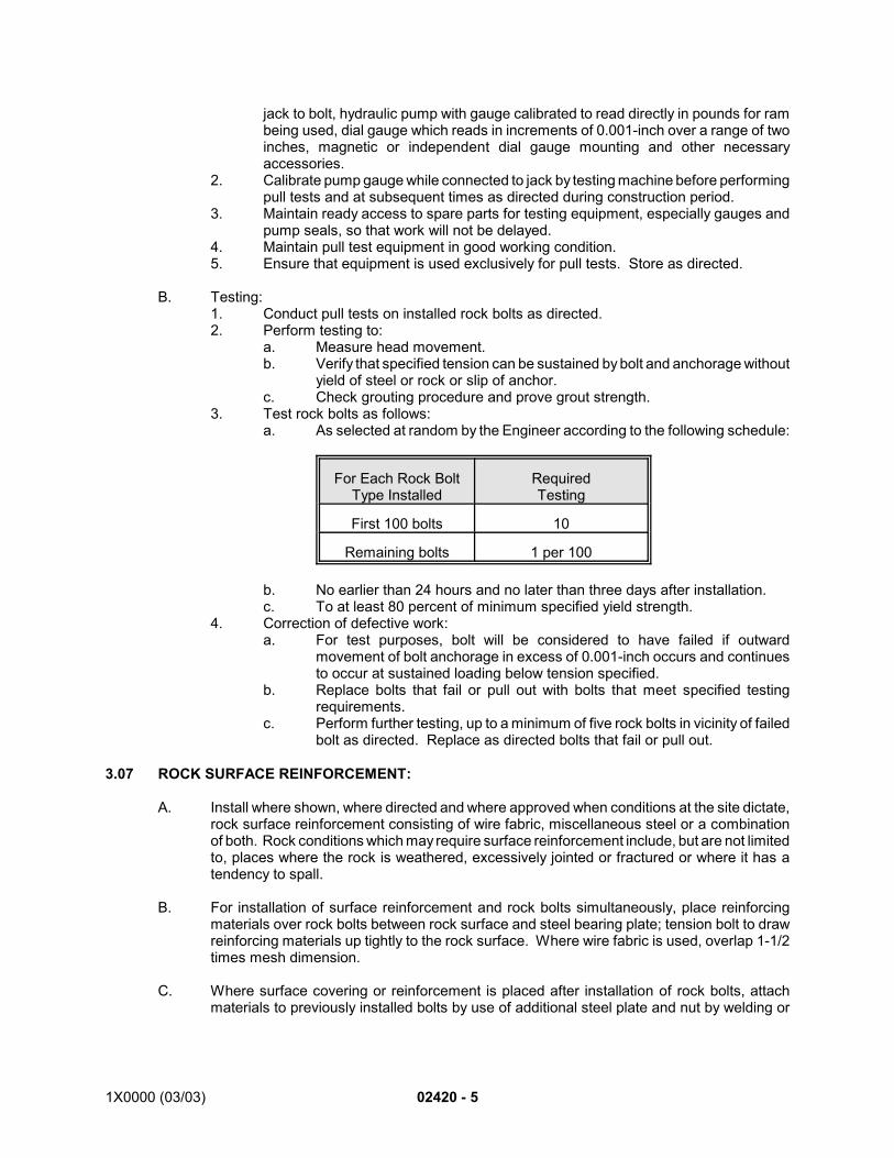
1X0000 (03/03) 02420 - 5
jack to bolt, hydraulic pump with gauge calibrated to read directly in pounds for rambeing used, dial gauge which reads in increments of 0.001-inch over a range of twoinches, magnetic or independent dial gauge mounting and other necessaryaccessories.
2. Calibrate pump gauge while connected to jack by testing machine before performingpull tests and at subsequent times as directed during construction period.
3. Maintain ready access to spare parts for testing equipment, especially gauges andpump seals, so that work will not be delayed.
4. Maintain pull test equipment in good working condition.5. Ensure that equipment is used exclusively for pull tests. Store as directed.
B. Testing:1. Conduct pull tests on installed rock bolts as directed.2. Perform testing to:
a. Measure head movement.b. Verify that specified tension can be sustained by bolt and anchorage without
yield of steel or rock or slip of anchor.c. Check grouting procedure and prove grout strength.
3. Test rock bolts as follows:a. As selected at random by the Engineer according to the following schedule:
For Each Rock BoltType Installed
RequiredTesting
First 100 bolts 10
Remaining bolts 1 per 100
b. No earlier than 24 hours and no later than three days after installation.c. To at least 80 percent of minimum specified yield strength.
4. Correction of defective work:a. For test purposes, bolt will be considered to have failed if outward
movement of bolt anchorage in excess of 0.001-inch occurs and continuesto occur at sustained loading below tension specified.
b. Replace bolts that fail or pull out with bolts that meet specified testingrequirements.
c. Perform further testing, up to a minimum of five rock bolts in vicinity of failedbolt as directed. Replace as directed bolts that fail or pull out.
3.07 ROCK SURFACE REINFORCEMENT:
A. Install where shown, where directed and where approved when conditions at the site dictate,rock surface reinforcement consisting of wire fabric, miscellaneous steel or a combinationof both. Rock conditions which may require surface reinforcement include, but are not limitedto, places where the rock is weathered, excessively jointed or fractured or where it has atendency to spall.
B. For installation of surface reinforcement and rock bolts simultaneously, place reinforcingmaterials over rock bolts between rock surface and steel bearing plate; tension bolt to drawreinforcing materials up tightly to the rock surface. Where wire fabric is used, overlap 1-1/2times mesh dimension.
C. Where surface covering or reinforcement is placed after installation of rock bolts, attachmaterials to previously installed bolts by use of additional steel plate and nut by welding or

02420 - 6 1X0000 (03/03)
by supporting with additional rock bolts. Check existing rock bolts to which extra steel plateand nut are added.
D. Replace installed bolts which become loose after attachment of surface reinforcement.
E. Firmly attach surface covering or reinforcement so that it closely follows approximate contourof rock.
END OF SECTION
1X000 (03/03) 02425 - 1
SECTION 02425
PRECAST-CONCRETE TUNNEL LINING
PART 1 - GENERAL
1.01 DESCRIPTION:
A. This section specifies providing precast-concrete segments for use as lining rings in one-pass tunnels with waterproofing gaskets and bolts, and as the initial lining of the two-passsystem tunnels. Precast concrete lining segments for the two-pass system may be eithergasketed and bolted when the initial liner needs to exclude water from tunnels being driven;or the segments may be jacked in place and retained by steel dutchmen and then grouted
B. Related Work Specified Elsewhere:1. Installation of the linings: Section 02415.2. Concrete formwork: Section 03100.3. Concrete reinforcement: Section 03200.4. Cast-in-place structural concrete: Section 03300.
1.02 QUALITY ASSURANCE:
A. Codes, Regulations, Reference Standards and Specifications:1. Comply with codes and regulations of the jurisdictional authorities.2. MS: MIL-23241 (Ships), MIL-P-26915 (USAF).3. FS: QQ-L-201, TT-S-230.4. ACI: 318.5. ASTM: A36, A123, A126, A153, A185, A325, A615, A706, C143, C309, C509,
D395, D412, D471, D2240, D2628, F436.6. AWS: D1.4.
B. Dimensional Tolerances:1. Fabricate segments to dimensions and tolerances shown. Contractor may use
closer tolerances if necessary for erection, watertightness or both.2. Maintain tolerances at mean temperature of 68F. Measure tolerances prior to
installation of gasket and elastomeric compression packing. Replace or correctsegments which do not comply with tolerances shown.
3. Determine the necessary taper of rings to cope with horizontal and vertical curvesor to correct misalignment, and submit details for approval.
4. Provide labor, tools, templates and facilities necessary for inspection ofmanufactured segments.
5.C. Demonstration Lining:
1. Before starting production of precast-concrete segments, furnish five-ring longsection of complete precast-concrete segment lining, including gasket, compressionpacking, exterior coating, nuts, bolts and accessories to demonstrate constructionof completed precast-concrete segment lining within tolerances shown. Include indemonstration lining two rings using tapered segments. For segments to beinstalled in earth tunnels include water-repellant treatment.
2. Assemble entire demonstration lining at job site, above ground, with longitudinal axisof rings horizontal. Provide temporary support structures such as base cradle andlateral bracing for such demonstration. Place rings in longitudinal compression usingidentical type of holding devices proposed for use in tunnel erection.
3. Notify the Engineer 15 days prior to installation of demonstration lining.
02425 - 2 (03/03) 1X000
4. Maintain demonstration lining until tolerances of completed lining are verified andremoval is approved. Dismantled segments may be used for permanent tunnellining, if approved.
5. If approval is withheld, dismantle demonstration lining as directed, adjust forms, castnew segments, if necessary, and erect new demonstration lining for approval.
D. Production Units:1. Commence production of segments only after written approval of demonstration
lining has been obtained.
E. Recorders: If casting is done at off-site plants, recorders described in Section 03300 are notrequired.
F. Tunnel Demonstration Lining:1. Construct one additional demonstration lining in initial 20 feet of tunnel. Erect the
lining within the tail of the shield utilizing the erection methods for this project. Thepurpose of this additional demonstration lining is to ensure that the tunneling anderection procedures are capable of erecting the complete tunnel lining to thespecified tolerances.
2. Stop tunneling after installation of the 20 feet (five rings) of demonstration lining untiltolerances are verified and approved.
3. If approval is withheld, submit proposed measures to rectify the 20-footdemonstration lining as well as proposed modification of procedures to ensuresatisfactory installation of the tunnel lining.
4. Do not resume tunneling until corrective measures are approved and implemented.5. After approval of corrective measures, construct an additional lining if required by the
Engineer.
G. Quality-Assurance Program for Gaskets: Before starting production of gaskets, providequality-assurance program to ensure that manufactured gaskets meet the samespecifications and quality as originally approved.
H. Rebar-Coating Applicator: Company approved by the Engineer specializing in hot-dipgalvanizing after fabrication.
I. Qualifications of Fabricator: Have precast-concrete segments fabricated by a firm withrecent continuous successful experience in the fabrication of precast-concrete structural unitswith tolerances equivalent to those specified in this section.
J. Adjust, if necessary, the gasket and gasket-groove dimensions to satisfy gasket testingrequirements specified in Article 3.3.B, with the approval of the Engineer.
1.03 SUBMITTALS:
A. Submit the following for approval in accordance with the General Requirements and with theadditional requirements as specified for each:1. Shop Drawings:
a. Include complete details of formwork, reinforcement, inserts andaccessories necessary for manufacturing, transportation and erection.1) Have drawings and design certified by a professional engineer
licensed to practice in the jurisdiction where the work is to beperformed.
2) Detailed design for segment lifting devices, providing for completeremoval of lifting device if device intrudes into tunnel space
b. Plant layout: Detailed flow diagram showing stages in manufacture ofsegments.
1X000 (03/03) 02425 - 3
c. Procedures:1) Detailed description of procedures for fabricating, handling,
transporting, storing and erecting segments, including calculationsof stresses during handling.
2) If the reinforcement shown on the Contract Drawings is inadequatefor the handling, storage, stacking and erection forces, includingjacking, provide additional reinforcement to compensate for theanticipated stresses at no additional cost to the Authority.
2. Samplesa. Exterior coal-tar epoxy coating: One quart.b. Gasket: One complete ring for each type.c. Compression packing: Two square feet.d. Adhesive: One pint of each kind used.e. Bolt, with washer, nut and grommet in sets: Two of each set.f. Sealant: Two tubes.g. Back-up rod: Three feet.h. Grout plugs: Two.i. Water-repellant treatment: One-quart container and one concrete panel, 12
inches square, treated on one side.j. Bolt sleeves, if required: Two.
3. Certification:a. Certified reports of successful testing by an independent testing agency
verifying that elastomeric joint-seal materials conform to the requirementsof ASTM D2628 for earth-tunnel segments and with ASTM C509 for rock-tunnel segments.
b. Certification that fabricator of segments has demonstrable experience in thefabrication of precast-concrete structural units similar to specified units asa predominant portion of its production.
c. Certification for concrete as specified in Section 03300.
1.04 PRODUCT DELIVERY, STORAGE AND HANDLING:
A. Precast Concrete Segments:1. Store and handle materials in accordance with Section 03300, with the following
additional requirements:a. Transport, store and handle segment units so as to prevent damage to
surfaces, edges and corners and to prevent development of stresses withinunits.
2. Keep units under cover and protected prior to installation.3. Protect mating surfaces of segments and gaskets from detrimental conditions during
transportation.4. The Authority retains the right to reject any segments structurally damaged as a
result of improper fabrication, handling, storing, stacking or transporting of thesegments.
5. Ship tapered units of complete rings, properly identified, when the segments are tobe bolted for erection.
6. Provide a positive means of identifying each segment, acceptable to the Authority.Identification markings must be cast in or stenciled on the interior face of thesegments.
B. Water-Repellant Treatment:1. Deliver products to the job site in their original unopened containers clearly labeled
with the manufacturer's name and brand designation, the referenced specificationnumber, and the quantity or net weight of contents.
2. Store products in an approved dry area and protect from contact with soil and fromexposure to the elements. Keep products from freezing.
02425 - 4 (03/03) 1X000
3. Handle products in a manner that will prevent breakage of container and damage tocontents.
C. Markings, including logos, trademarks and proprietary information, but excluding panel-identification markings, are prohibited on surfaces of tunnel-lining segments.
1.05 JOB CONDITIONS:
A. Environmental Requirements:1. Do not apply water-repellant treatment to unprotected surfaces in wet weather or to
surfaces on which ice, frost, or water is present.2. Do not apply water-repellant treatment unless the ambient temperature is at least
50F and rising unless approved in writing.3. Provide ventilation in accordance with specified safety requirements.
PART 2 - MATERIALS:
2.01 MATERIALS:
A. Concrete:1. Section 03300, with not less than seven bags of cement per cubic yard of concrete,
with the following additional requirements as determined by ASTM C143:a. Rock-tunnel segments: Class 5000.b. Earth-tunnel segments: Class 8000.c. Initial liner segment for two-pass tunnel: Class 6000.d. Use mix of portland cement and ground-iron blast-furnace slag. Blast-
furnace slag amount not to exceed 50 percent of the cement weight.2. Admixtures, if used, to contain no chlorides, fluorides or nitrates.3. Maximum size of aggregate: 3/4 inch.
B. Reinforcement: Section 03200, with the following additional requirements:1. Rock-tunnel segments: Welded-wire fabric, ASTM A185.2. Earth tunnel segments: ASTM A706, Grade 60 and ASTM A615, Grade 60. When
welding of the reinforcing bars is required, use ASTM A706, Grade 60 bars.Conform to the Structural Welding Code–Reinforcing Steel, AWS D1.4 for thewelding of reinforcing bars.a. Liner rebar cage: Hot-dip galvanized, Section 05120. Coat reinforcing
cages after assembly and welding.
C. Inserts, Anchors, Dowels and Accessories: Steel, ASTM A36 or equal; zinc-coated inaccordance with ASTM A123. *1
D. Gasket:1. Elastomeric seal: ASTM D2628.2. Manufactured as continuous ring sized to fit panels snugly, formed to shape and size
shown, with gasket corners molded, mitered and vulcanized to provide uniformthickness along entire length of mating surfaces.
3. Hardness: ASTM D2240, Shore A Durometer, as follows:a. Rock-tunnel segments: 40, plus-or-minus fiveb. Earth-tunnel segments: 55, plus-or-minus five.
4. Tensile strength: ASTM D412, 2,250-psi minimum, minus 10 percent.5. Elongation: ASTM D412, 300-percent minimum, minus 25 percent.6. Water absorption: ASTM D471, 24 hours at 212F, 10-percent maximum by weight.7. Compression set: ASTM D395, Method B, 70 hours at 212F, 25-percent maximum.8. Fire rating: Self extinguishing.
1X000 (03/03) 02425 - 5
9. Dimensional tolerances: Plus-or-minus three percent.10. Stress relaxations: 25 percent.11. Contact pressure: Between 200 psi and 400 psi, as determined by specified
compression test. *2
E. Compression Packing:1. Neoprene sheet: 30 mils thick.2. Hardness: ASTM D2240, Type A Durometer, 65, plus-or-minus five.
F. Adhesive:1. As recommended by manufacturer of compression packing and gasket and
compatible for conditions of application, including areas of applied waterproofing.2. Use solution recommended by manufacturer for cleaning elastomers at time of
segment installation.
G. Exterior Coating:1. Coal-tar epoxy, MS MIL-P-23241 (Ships), Type 1, Class 2.2. Thinner: As recommended by coating manufacturer.
H. Bond Breaker: Section 03100, non-staining.
I. Grout Plugs:1. ASTM A126, Class B, 1-1/2 inch NSPM external threads, galvanized in accordance
with ASTM A153, threads coated with thread sealing compound SEAL UNYTE or T-UTYPE 555 manufactured by J.C. Whitman Manufacturing Company, Wadsworth,Ohio, or approved equal.
2. Lead washer: FS QQ-L-201.J. Fasteners:
1. Bolts and nuts: ASTM A325, Type I, galvanized. Bolts to have rolled threads.2. Washers: ASTM F436, galvanized.3. Grommets: Low-density polyethylene, hardness Shore D Durometer 45 to 55, ASTM
D2240, configuration to seal bolt holes under conditions of maximum misalignment.
K. Water-Repellant Treatment: Acrylic, water-emulsion, ASTM C309.
L. Grout: Section 02415.
M. Sealant: Siloxane polymer and fillers, FS TT-S-230.1. Backup rod: Polyethylene rod, closed cell, 5/8-inch diameter.
N. Primer: Zinc-rich primer, MS MIL-P-26915 (USAF), Type 1, Class
O. Bolt Sleeves: Low-density polyethylene, ribbed, hardness Shore D Durometer 45 to 55,ASTM D2240, minimum 1/8-inch wall thickness plus ribs, configuration as shown.
PART 3 - EXECUTION
3.01 FABRICATION:
A. Formwork:1. Fabricated of steel.2. Special sizes and cross sections as shown, with metal thickness, reinforcement,
stiffness and surface finish as necessary to form concrete surfaces that are smooth,free of irregularities, welding blemishes and concrete stain.
02425 - 6 (03/03) 1X000
3. Machine form surfaces for contact faces of segments to tolerance of plus-or-minus0.016 inch.
4. Clean and coat forms with bond breaker prior to each reuse.5. Ensure smooth surfaces for application of adhesive.6. Accurately place reinforcing steel with tolerances in accordance with ACI 318.7. Securely anchor form inserts and embedded items to formwork.8. Mix and place concrete in accordance with Section 03300.
3.02 CURING:
A. Cure by steam in accordance with the following requirements:1. Immediately after segments have been cast, enclose forms in an enclosure capable
of vapor tight sealing to prevent escape of moisture and heat, and which is largeenough to allow complete circulation of steam.
2. Introduce saturated steam into enclosure and maintain atmosphere in a saturatedcondition until compressive strength of 4,000 psi is attained, as determined by testcylinders. Do not attempt removal of segments from forms until 4,000 psicompressive strength is attained. The Engineer reserves the right to requirecompressive strength up to 0.75f’c, if there is evidence of distortion, cracking,spalling or similar damage which could occur during handling and storage ofsegments.
3. Enclosure ambient temperature: Not to exceed 100F for first two hours of curing.Thereafter, maintain temperature within 95F to 150F until specified curing strengthis achieved.
4. Do not allow rate of change of temperature to exceed 30F per hour.5. When specified strength is attained, allow segments to cool slowly but not exceeding
rate of change specified in subparagraph 4. above.
3.03 TESTING:
A. Test in accordance with Section 03300, with the following additional requirements:1. Mix design and curing strength test:
a. Prior to manufacture establish concrete mix that will produce concrete ofspecified compressive strengths and submit data for approval.
b. After approval of initial mix design has been obtained, make six cylindersfrom each single batch of concrete.
c. Obtain prior approval of changes in mix design during segmentmanufacture.
d. Prepare, cure and test cylinders in accordance with procedures specified forsegment manufacture.
e. For cylinders prepared prior to manufacture:1) Remove in pairs at appropriate time intervals during curing and test
immediately upon removal to establish correct curing duration andcompressive strength.
f. For cylinders prepared as result of change in mix design and as directed:1) Follow procedures specified for cylinders prepared prior to
manufacture.2) Obtain approval of test results prior to manufacture of segments
using new mix design. Inclusion or exclusion of any additives oradmixtures to be treated as a change in mix design.
B. Production test cylinders:1. Prepare three cylinders and cure as specified for each work shift or each 100 cubic
yards of concrete used, whichever is more frequent.a. Test cylinders in accordance with Section 03300.
1X000 (03/03) 02425 - 7
b. 28-day compressive strength: 85 percent of cylinders to meet specifiedcompressive strength.
C. Gasket Testing:1. Compression test:
a. Testing device:1) Hydraulic equipment capable of applying 20,000-pound force with
load-scale capable of reading up to 20,000 pounds in 20-poundincrements.
2) Two steel plates 16 inches by five inches by 1-1/2 inches thick,each plate with machined groove having dimensions and geometryof gasket groove in precast-concrete segments on one side.
3) Minimum 3/4-inch diameter rod by which upper steel plate isattached to hydraulic equipment.
b. Test preparation:1) Attach compression packing to high side of groove on each plate.2) Cut two pieces of gasket 16 inches long and attach one to each
plate with contact cement. Center gasket in groove.3) Attach steel end plates on both sides of bottom plate to prevent
longitudinal deformation of both top and bottom gaskets.4) Prepare bed of grout underneath bottom plate. Bring upper plate
in contact with lower plate. Apply pressure until grout squeezes outfrom below bottom plate. Ensure that gaskets are properly alignedby placing 1/8-inch spacer between low sides of grooves while groutis setting. Leave in position until grout sets.
c. Test:1) Apply pressure at rate of 400 lb/min. until closure is completed.2) Calculate closure pressure based on two-inch width of gasket.3) Record, calculate and submit closure load (lb.), gasket thickness
(inches), length of gasket (inches), load rate (lb/min) and closurepressure (psi).
d. Test supervision: Have all phases of mechanical test supervised by testengineer with experience in similar test procedures.
2. Leakage test:a. Testing device:
1) Two steel plates 16 inches by 16 inches by two inches thick withmachined groove running along perimeter of plates and havinggeometry and dimensions of gaskets grooves in precast-concretesegments. Centerline of groove 2-1/2 inches from plate edge. Lowside of groove to center of plate. Plates shall have 5/8-inchdiameter holes evenly spaced around perimeter of plate betweengroove and edge. Both plates identical and symmetrical aboutcenterline.
2) Eight 1/2-inch bolts capable of resisting 5,000-pound force.3) Steel water tank, filled with water.4) Nitrogen tank under 2,200-psi pressure with regulator.5) Gasket material having passed mechanical test.
b. Test preparation:1) Place gasket in groove by cutting 45-degree angles in ends of four
equal pieces and gluing them together in a square with Super Glueor equal. Lengths of four pieces of gasket selected so as to fitsquarely in groove of each steel plate. Attach gasket to each plateby means of contact cement.
2) Attach compression packing to high side of groove on each platewith contact cement.
02425 - 8 (03/03) 1X000
3) Provide vent hole for escaping air pressure, and inlet hole for water,in center of top plate.
4) Bolt both plates together, tightening bolts until plates just close.c. Test:
1) Attach water tank to plates. Add water to vent out air. Plug venthole.
2) Apply 200-psi pressure to water tank with nitrogen tank. Recordpressure through gauge in nitrogen to water-tank line.
3) Record pressure and inspect for leakage daily during period of onemonth. Submit result to the Engineer.
4) Gasket will be accepted if no leakage is observed during entireduration of test.
d. Have all phases of mechanical test supervised by test engineer withexperience in similar test procedures.
3. Frequency of tests: Perform both compression and leakage tests on gasket beforeproduction begins and at 25-percent, 50-percent and 75-percent production levels.
3.04 INSTALLATION OF GASKET:
A. Prior to installation of gasket, apply water-repellant treatment to surface as shown.
B. Use gasket adhesive as recommended by manufacturer of gasket at intervals ofapproximately 15 inches.
C. Fit gasket snugly into groove provided around segments.
3.05 INSTALLATION OF COMPRESSION PACKING:
A. Clean surface as necessary. Apply adhesive in accordance with manufacturer'srecommendations.
B. Cut elastomeric compression packing to proper dimensions and affix as shown.
3.06 EXTERIOR-COATING APPLICATION:
A. Apply coating to exterior surfaces of segments. Do not coat mating surfaces or sealantgrooves.
B. Apply coating in two coats of equal thickness totaling 20-mil minimum dry-film thickness andin strict accordance with recommendations of manufacturer of protective coating, includingpretreatment of first coat prior to application of second coat.
C. Apply second coat before first coat has dried tack-free and not later than 24 hours afterapplication of first coat, unless otherwise specified by coating manufacturer.
3.07 APPLICATION OF WATER-REPELLANT TREATMENT:
A. Preparation:1. Apply water-repellant treatment only after concrete has cured as specified in Section
03300.2. Remove from surface to be treated dust, dirt, debris, oil, grease and other foreign
matter. Prepare surfaces to be treated in accordance with treatment manufacturer'srecommendations.
B. Installation
1X000 (03/03) 02425 - 9
*1. Other joint connection systems, eg. coil inserts, tylags, plastic washers, etc., to be included inspecifications by the Section Designer.
*2. To be specified by the Section Designer.
END OF SECTION
1. Apply one base coat of water-repellant treatment to segment surfaces as shown andin accordance with manufacturer's recommendations.
2. Allow a minimum of 24 hours elapsed time between treatment-coating applications.
3.08 TUNNEL BREAKOUT
A. Provide special liner segments and special lining rings, complete with steel frame andtemporary bracing, where shown.
B. Upon completion of the tunnel breakout, remove and dispose of the special liner segmentsand special lining rings.
SEE ENDNOTES BELOW. THEY ARE AN ESSENTIAL PART OF THIS SECTION UNTIL EDITED BYSECTION DESIGNER.
ENDNOTES:
1X0000 (03/03) 02426 - 1
SECTION 02426
NATM SHOTCRETE LINING
PART 1 - GENERAL
1.01 DESCRIPTION:
A. This section specifies the shotcrete lining applied following NATM excavation.
B. Related Work Specified Elsewhere:1. NATM excavation: Section 02417.2. Shotcrete: Section 03370.3. NATM concrete lining: Section 02427.4. Tunnel waterproofing (NATM system): Section 07138.
1.02 QUALITY ASSURANCE:
A. Codes, Regulations, Reference Standards and Specifications:1. Comply with codes and regulations of the jurisdictional authorities.2. ASTM: A36, A185, A325, A615, A706, C144, C150, C579.
B. Installer with a minimum of two years experience.
C. Lattice girder tolerances as certified by engineer’s calculations.
1.03 DEFINITIONS:
A. Shotcrete: Section 03370.
B. Lattice Girder: A lightweight, three-dimensional steel frame made to act as a unit byconnecting components with lacing bars used in conjunction with shotcrete for shotcretelining reinforcement.
C. Splice Bar: Rebar installed to provide inherent connection of shotcrete in circumferentialdirection between top heading and bench shotcrete and at break-outs from cut-and-coverstructures.
D. Splice Clip: Rebar installed at arch lines as means of longitudinal reinforcement of theshotcrete lining.
E. Local Support: See Section 02417.
F. Pre-support: See Section 02417.
G. Girder Brace: Rebar installed between two adjacent lattice girders for lateral support oflattice girders.
H. Soil Anchor: Steel bar installed in borehole on the tunnel shotcrete lining and fullyencapsulated in cement mortar grout with accelerator cartridge when and where shown ondrawings.
I. Forepoling or Spiling Bar: Steel bar without end hardware installed at the tunnel heading byjacking or other mechanical equipment.
02426 - 2 1X0000 (03/03)
J. Forepoling Sheets: Steel plate installed at the tunnel heading by jacking using mechanicalequipment to provide earth support during excavation.
K. Grouting: Methods used for pre-support of tunnel excavation and ground stabilization bypressure injecting chemical grout or cement grout.
1.04 SUBMITTALS:
A. Submit the following for approval in accordance with the General Requirements and with theadditional requirements as specified for each:1. Shop Drawings:
a. Shotcrete lining indicating structural construction details.b. Show relationship of waterproofing and concrete lining elements to
shotcrete lining elements and to the plan and sequence of excavation andlining installation.
c. Show relationship of shotcrete lining to intermediate excavation and supportstages at break-out of tunnel and at interfaces.
d. Design, specifications, method of operation and other data pertaining to thefollowing:1) Fabrication details for lattice girders.2) Welded wire fabric, splice bars, and splice clips.3) Rebar spiles and perforated steel pipes.
2. Documentation:a. Calculations for lattice girder connection details. Have these calculations
certified by a professional engineer registered in the jurisdiction where thework is being performed.
b. Tolerances: Include engineer’s statement of acceptable tolerances in thecertified calculations.
3. Samples:a. Lattice Girders: Submit a two foot long sample of lattice girder with its
accessories which shows full cross section and type to be used. Submitthree such samples of lattice girder.
b. Soil Anchors: Anchor bolts and accessories: Three samples of each.c. Accelerator Cartridge: Three samples.d. Forepoling Sheets and Bars: Three sample sections one foot long showing
full cross section and type to be used.4. Testing:
a. Prior to installation of soil anchor, arrange demonstration to show thatspecified pull out strength requirements can be met.
1.05 JOB CONDITIONS:
A. Maintain a minimum of a five-day supply of lattice girders and shotcrete on site to preventdelays to the work. Maintain constant and adequate supply of shotcrete at tunnel headingduring excavation, such that shotcrete may be applied at any time.
1.06 PRODUCT DELIVERY, STORAGE AND HANDLING:
A. General:1. Load, transport, unload and store structural materials to keep them clean and free
from damage.
1X0000 (03/03) 02426 - 3
2. Store material on platforms, skids or other supports above ground and ensure properdrainage and protection from corrosion.
B. Lattice Girders:1. When handling and shipping lattice girders prevent bending, scraping or
overstressing members.2. Block projecting parts likely to be bent or damaged during handling with wood or
other approved material.3. Replace pieces bent or damaged unless repair is approved.
PART 2 - PRODUCTS
2.01 MATERIALS:
A. Shotcrete: Section 03370.
B. Welded Wire Fabric: ASTM A185, Size 6 x 6 - W4.0 x W4.0.
C. Splice Bar: Fabricated from No. 4 standard reinforcing steel conforming to ASTM A615Grade 60 as shown.
D. Splice Clips: Fabricated from No. 5 standard reinforcing steel conforming to ASTM A615Grade 60 as shown.
E. Lattice Girder:1. General:
a. Fabricate lattice girders to consist of three primary retaining bars,dimensioned and arranged as shown and connected by stiffening elementsof the manufacturer’s design or as shown and from rebars conforming toASTM A706 Grade 60.1) Facilitate shotcrete penetration into and behind the girder, thereby
minimizing the creation of injection shadows.2) Provide optimum bonding between the steel and shotcrete in order
to form a composite, continuous, reinforced shotcrete liningstructure.
b. Provide lattice girders with moment properties about the neutral axes in asection perpendicular to the longitudinal axis of the border, as shown. Havethe stiffening elements provide a minimum five percent of the total momentsof inertia. This percentage is calculated as an average value alongrepeatable lengths of the lattice girder.
c. Ensure stability against buckling. Maintain the maximum spacing betweenstiffening elements at less than three times the cross sectional height of thegirder.
2. Dimensions:a. As shown.b. Fabricate the lattice girders to meet minimum clearances shown under
consideration of inaccuracy of placement during construction, materialtolerances, and of lining deflection following installation.
3. Testing:a. Test lattice girder segments of typical length randomly selected by the
Engineer from the standard stock. The Engineer will observe the testing.b. Test segments in single point flexure with loading and constrains
representative of the in-situ conditions of the girder. Record measurementsof the gradually applied load and deflection of the girder at the point of
02426 - 4 1X0000 (03/03)
application until failure occurs to verify that the girder satisfies the minimumstructural requirements.
c. Replace faulty lattice girders at no additional cost to the Authority.
F. Soil Anchors: Anchor Bolts and Accessories:1. General Requirements:
a. Soil anchor assembly: Anchor bolt, anchor plate, washer and nut.b. Fabricated from No. 6 standard deformed reinforcing steel bar suitably
threaded conforming to ASTM A615 Grade 60.c. Approved method of anchorage to take specified tension.d. Anchor plate: Plate 3/8-inch thick conforming to ASTM A36 having bearing
area of at least 64 square inches.e. Nuts: Hexagonal head, ASTM A325.f. Steel washers: Center hole to be 1/8-inch larger in diameter than bolt with
which it is to be used. Flat or conical shape conforming to ASTM A325.g. Grout and mortar:
1) Cement: ASTM C150 Type 1.2) Water: Section 03300.3) Sand: ASTM C144.4) Accelerator cartridge: Accelerator cartridge to be such that pull out
strength of 5,000 pounds is achieved within 20 minutes.
G. Forepoling or Spiling Bars: Fabricated from No. 8 standard reinforcing steel conforming toASTM A615 Grade 60 as shown.
H. Forepoling Sheets: Steel ASTM A36.
I. Girder Brace: Fabricated from No. 6 standard reinforcing steel conforming to ASTM A615Grade 60 as shown.
2.02 FABRICATION:
A. Provide each of the primary retaining bars of lattice girder segment in one piece, that iswithout splice, of high strength steel having a yield strength of 60 ksi.
B. Construct the connection elements at the end of the lattice girder segments of structural steelangles having a yield strength of 36 ksi or stronger, or of welded flat steel ensuring similarstrength characteristics.
C. Fabricate steel supports in accordance with Section 05120, except as follows1. Inspection of groove and fillet welds by visual inspection only.2. Grinding to remove nicks resulting from flame cutting is not required.3. Planing and facing of sheared edges or bearing surfaces is not required.4. Subpunching or subdrilling of bolt holes is not required.5. Portions of nearing members such as butt and foot plates need not be straightened,
planed and connected after fabrication.
PART 3 - EXECUTION
3.01 GENERAL:
A. Install shotcrete lining as shown and specified herein, and in accordance with applicablerequirements of Section 02417.
1X0000 (03/03) 02426 - 5
B. Verify that the ground types encountered in the tunnels or station excavation are the sameas were considered in the design. If not, make the necessary changes to the excavationsequence with the prior approval of the Engineer.
C. Excavation sequences of headings as shown for Excavation and Support Type 1 and Type2.
3.02 FLASH-CRETE:
A. Install as shown and as specified in Section 02417.
3.03 LATTICE GIRDERS:
A. Install to conform to excavated shape as shown. Consider inaccuracy of construction,tolerances of materials, and initial lining deflection to determine actual dimensions. Provideminimum embedment as shown.
B. Secure lattice girder segments by use of girder braces, temporary wood blocking and otherappropriate means to maintain position during shocreting.
C. Provide butt plates of lattice girder segments and expansion unit in invert as shown orotherwise approved by Engineer. Ensure tight connection of elements.
3.04 WELDED WIRE FABRIC:
A. Install as shown. Provide minimum overlap of 12 inches in each direction or use splice barsas shown.
3.05 SPLICE BARS AND SPLICE CLIPS:
A. Install splice bars and splice clips for additional reinforcement as shown.
3.06 SHOTCRETE:
A. Install shotcrete lining to provide required shotcrete lining thickness as shown.
3.07 SMOOTHNESS CRITERIA:
A. General Smoothness Criteria: Provide shotcrete with a surface meeting the followingtolerance:1. Shotcrete lining: Depth-to-wavelength ratio as measured with a 10-foot straightedge
in random direction to be 1/5 or less.
3.08 DETECTION OF MOVEMENT:
A. As specified in Section 02417.
3.09 FIELD QUALITY CONTROL:
A. As specified in Sections 02417 and 03370.
END OF SECTION
1X0000 (08/01) 02427-1
SECTION 02427
NATM CONCRETE LINING
PART 1 - GENERAL
1.01 DESCRIPTION:
A. This section specifies cast-in-place concrete lining installation in NATM tunnels.
B. Related Work Specified Elsewhere:1. NATM shotcrete lining: Section 02426.2. Concrete formwork: Section 03100.3. Concrete reinforcement: Section 03200.4. Cast-in-place structural concrete: Section 03300.5. Shotcrete: Section 03370.6. Tunnel waterproofing (NATM system): Section 07138.7. Drilling and pressure grouting for rock tunnels: Section 02431.8. NATM excavation (soft ground): Section 02417.
C. Definitions:1. NATM: New Austrian Tunneling Method.
1.02 QUALITY ASSURANCE:
A. Comply with the requirements of Sections 03100, 03200 and 03300.
1.03 SUBMITTALS
A. Comply with the requirements of Sections 03100, 03200 and 03300.
PART 2 - PRODUCTS
2.01 MATERIALS:
A. Comply with the requirements of Sections 03100, 03200 and 03300.
PART 3 - EXECUTION
3.01 INSTALLATION OF CONCRETE LINING:
A. Perform concrete work in accordance with Sections 03100, 03200 and 03300.
B. Place concrete for lining upper portion of tunnel by mechanical or pneumatic methodsthrough pipes which discharge as nearly as practicable to highest point of structure.
C. Prior to placement of concrete, remove materials within concrete design lines so as to avoidcompromising stability of shotcrete lining and surrounding ground.
D. Fill enlargement of tunnel excavation beyond theoretical outer limit of concrete lining shownwith concrete.
02427-2 1X0000 (08/01)
E. Force concrete into contact with waterproofing.
F. Schedule erection of concrete tunnel lining so that no concrete is placed closer than 500 feetfrom tunnel excavation heading, unless otherwise approved.
G. Contact Grouting: Perform contact grout as specified in Section 02431 and 02417 and asfollows:1. Perform contact grouting through grout pipes in roof, in such quantity and at
sufficient pressure to fill all voids. Maximum allowable grouting pressure for contractgrouting is not to exceed 20 psi.
2. Pump grout until grout comes through adjacent grout pipes in the roof.3. Perform contact grouting behind concrete lining when concrete is more than 28 days
old.
3.02 DEFECTIVE LINING:
A. Concrete tunnel lining is considered defective unless it is watertight, properly finished, iswithin specified tolerances and has undamaged surfaces and joints.
B. Watertightness criteria: Section 03300.
C. Cast-in-place concrete lining is considered defective if misalignments cause tunnel wall tobe less than 12 inches thick.
3.03 CORRECTIVE WORK:
A. Repair of concrete: Repair concrete having minor chipping of surfaces using epoxy mortarhaving surface color and texture closely matching adjacent concrete surfaces. As directed,repair or replace with new concrete those cracked portions which impair structural integrityof tunnel lining as determined by the Engineer.1. Ensure that surfaces to be repaired are clean, dry, free from dirt, dust, oil, water and
other contaminants.2. Mix and place epoxy mortar as recommended by the manufacturer. Grind rough or
raised projections smooth and flush with adjacent surfaces.
B. If cast-in-place concrete lining thickness falls below nine inches, to maintain line and grade,remine tunnel so that concrete lining thickness is at specified minimum thickness.1. Remine as specified in Section 02417.
3.04 LEAK REMEDIATION:
A. Leak remediation: Section 07138.
END OF SECTION
1X0000 (03/03) 02431-1
SECTION 02431
DRILLING AND PRESSURE GROUTING FOR ROCK TUNNELS
PART 1 - GENERAL
1.01 DESCRIPTION:
A. This section specifies drilling feeler, exploratory, drainage and other holes, furnishing andinjecting grout and patching finished grout holes in rock tunnels
B. Definitions:1. Contact grouting: Injection of grouting material at crown areas of tunnels to fill voids
between tunnel lining and surrounding rock.2. Consolidation grouting: Injection of grouting material through holes drilled up to 25
feet long at appropriate intervals around periphery of rock tunnel prior to installationof lining.
1.02 QUALITY ASSURANCE:
A. Codes, Regulations, Reference Standards and Specifications:1. Comply with codes and regulations of the jurisdictional authorities.2. ASTM: A53, C109, D1785, D2466.
B. Qualifications:1. When taking rock cores, employ only experienced rock core-drilling personnel.
C. Tests:1. Determine strength of cementitious grout from test specimens made and tested in
accordance with ASTM C109.
1.03 SUBMITTALS:
A. Submit the following for approval in accordance with the General Requirements and with theadditional requirements as specified for each:1. Working Drawings:
a. Details of grout mix composition. Submit prior to grouting.2. Documentation:
a. Rock core logs prepared as approved. Submit daily.1) Include descriptions as follows:
a) Materials of whatever character encountered in drilling andtheir locations in the holes.
b) Length of each run with percentage of core recovery.c) Location of special features such as mud seams, open
cracks and soft or broken ground.d) Points where abnormal loss or gain of drill water has
occurred.e) Groundwater levels or other items of interest in connection
with grouting in exploratory drilling.f) Significant actions of bit and reasons for loss of core.
3. Rock Cores:a. Place entire rock cores in boxes in same order they are recovered from
each hole. Use wooden blocks to show lengths of core not recovered.
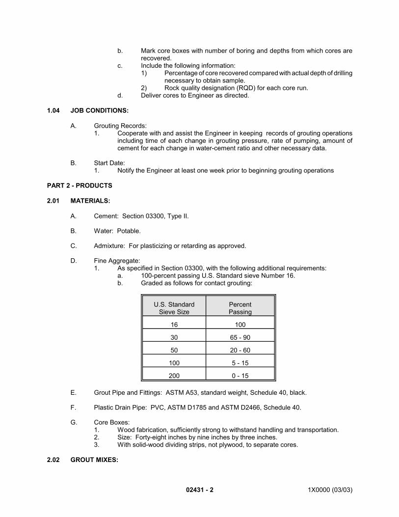
02431 - 2 1X0000 (03/03)
b. Mark core boxes with number of boring and depths from which cores arerecovered.
c. Include the following information:1) Percentage of core recovered compared with actual depth of drilling
necessary to obtain sample.2) Rock quality designation (RQD) for each core run.
d. Deliver cores to Engineer as directed.
1.04 JOB CONDITIONS:
A. Grouting Records:1. Cooperate with and assist the Engineer in keeping records of grouting operations
including time of each change in grouting pressure, rate of pumping, amount ofcement for each change in water-cement ratio and other necessary data.
B. Start Date:1. Notify the Engineer at least one week prior to beginning grouting operations
PART 2 - PRODUCTS
2.01 MATERIALS:
A. Cement: Section 03300, Type II.
B. Water: Potable.
C. Admixture: For plasticizing or retarding as approved.
D. Fine Aggregate:1. As specified in Section 03300, with the following additional requirements:
a. 100-percent passing U.S. Standard sieve Number 16.b. Graded as follows for contact grouting:
U.S. StandardSieve Size
PercentPassing
16 100
30 65 - 90
50 20 - 60
100 5 - 15
200 0 - 15
E. Grout Pipe and Fittings: ASTM A53, standard weight, Schedule 40, black.
F. Plastic Drain Pipe: PVC, ASTM D1785 and ASTM D2466, Schedule 40.
G. Core Boxes:1. Wood fabrication, sufficiently strong to withstand handling and transportation.2. Size: Forty-eight inches by nine inches by three inches.3. With solid-wood dividing strips, not plywood, to separate cores.
2.02 GROUT MIXES:
1X0000 (03/03) 02431-3
A. Grout for Contact Grouting:1. Consisting of one part portland cement, one part fine aggregate and approved
admixture or as otherwise approved.2. Minimum compressive strength: 100 psi within 24 hours.3. Fluid enough to be injected to fill voids.4. Comprising ingredients not corrosive to steel.
PART 3 - EXECUTION
3.01 EQUIPMENT:
A. For exploratory core drilling, use approved drilling equipment with double-tube core barrel toobtain continuous NX, minimum size cores, 2-1/8 inches diameter.
B. For feeler, grout and drain holes, use rotary or percussion-drilling equipment.
C. For pumping grout, use approved pump capable of developing appropriate, approved,uniform pressure at grout hole connection and hoses with inside diameter of 1-1/2 inchesminimum.
D. Use horizontal shaft paddle or colloidal pump mixer with minimum capacity of 20 cubic feetand with accurate meter which reads to nearest 1/10-cubic foot for measuring amount ofmixing water added to grout.
E. Provide approved pressure gauges at grout pump and on manifold hookup at collar of holebeing grouted.
3.02 FEELER HOLES:
A. Drill feeler holes as directed ahead of excavation to determine in advance nature andcondition of materials to be excavated.
B. Drill each hole to diameter of 1-1/2 inches minimum and length of 15 feet minimum and 30feet maximum.
C. While drilling feeler holes, suspend or modify other operations as necessary to permit suchdrilling. Drill holes only in the presence of the Engineer.
D. Obtain approval for location, direction, length and number of holes.
3.03 EXPLORATORY HOLES:
A. Drill exploratory holes in order to determine type and quality of rock.
B. Depending on nature of rock, select length of drill run to ensure maximum core recovery, butin no case to exceed five feet.
C. Package cores as specified and deliver to the Engineer as directed.
D. Unless otherwise directed, pressure grout exploratory holes after removal of core.
3.04 DRAIN HOLES:
A. Locate and drill holes where shown or as directed. Keep holes clear of obstructions.
02431 - 4 1X0000 (03/03)
B. Use plastic pipe for weep holes where shown. Fasten fittings with adhesive or threads.
3.05 GROUTING:
A. General Requirements:1. Grout holes:
a. Drill grout holes in rock or lining to diameter of two inches minimum and asshown or as directed or use existing grout holes.
b. Avoid cutting embedded steel. If steel is encountered, cease cutting andpatch hole.
c. Clean obstructed holes for entire depth prior to grouting.d. Thoroughly wash grout holes immediately before starting pressure grouting.
2. Pipes and fittings:a. Place pipes to be embedded in tunnel lining for contact-grout connections
and air vents as shown.b. Set inner end of pipes not less than two inches back from finished inside
surface and provide recesses from there to surfaces of lining. Fill recesseswith concrete or mortar after grouting operations have been completed.
c. Set grout pipes so that grout flows freely to voids behind lining.d. Hold pipes to be embedded firmly in position and protect from damage while
concrete is being placed. Provide and attach caps or other devices to endsof pipe to prevent entry of concrete or other foreign materials prior togrouting and to facilitate location of grout pipe after forms are removed.
e. Avoid clogging or obstructing pipes before grout hookups are made. Cleanclogged or obstructed pipes.
3. Connections:a. Make connections so as to prevent leakage.b. Remove plugs on ends of grout holes or pipes to permit escape of air and
water and filling of spaces with grout.c. Provide straightway cock or valve at each connection.
4. Grouting operations:a. Perform grouting operations in the presence of the Engineer.b. Use grout of consistency to suit the characteristics of the hole being grouted
or the type of grouting being performed.c. Use approved pressure at hole.d. Consider grouting hole to be complete when hole refuses grout at 90
percent of highest pressure approved.e. Upon completion of grouting at each connection, close valve and leave it in
place until grout has set.f. After grout has set remove valves and fittings and metal connections to
depth of 1-1/2 inches minimum from face of concrete.g. Fill grout holes with thick grout or dry pack at completion of grouting
operations to leave smooth finished surface.h. Do not block drains or drain lines during grouting operations.i. Clean drains after each grouting operation.
B. Consolidation Grouting:1. Perform consolidation grouting as necessary.2. If consolidation grouting has to be performed after contact grouting, allow at least
seven days to elapse between completion of contact grouting and beginning ofconsolidation grouting.
3. Perform consolidation grouting within radius of 50 feet of cast-in-place concretetunnel lining only when lining is more than 14 days old.
C. Contact Grouting:
1X0000 (03/03) 02431-5
1. Perform contact grouting through holes drilled or placed in tunnel lining whereshown.
2. Obtain approval of grouting pattern and order of grouting prior to start of contactgrouting.
3. Provide vent pipes to suit conditions encountered.4. Perform contact grouting behind concrete liner when concrete is more than 14 days
old.5. Use maximum pressure for contact grouting as approved.6. Continue grouting until clear grout stream emerges from vent pipe.7. Allow at least seven days after completion of contact grouting, before beginning
further grouting.
END OF SECTION
02460 - 1 1X0000 (08/01)
SECTION 02460
PILES
PART 1 - GENERAL
1.01 DESCRIPTION:
A. This section specifies furnishing and installing bearing piles, performance of Static Pile LoadTests and Dynamic Pile Testing.1. Sequence of Work:
a. Conduct initial wave equation analysis, prepare Indicator Pile Order List andsubmit information to Engineer for review.
b. Piles shall not be driven until embankments or excavations shown havebeen completed to the specified grade.
c. Obtain and drive the indicator piles where shown on the drawings. Duringinitial driving perform Dynamic Pile Testing and the refined wave equationanalysis on each indicator pile to confirm the length, and control blow count.Determine pile driving criteria on the basis of the pile driving analysis (PDA)during the initial driving and the static load test. Incorporate results intodriving of subsequent indicator piles.
d. Perform Static Pile Load Tests per Article 3.2.B.2 on indicator pilesdesignated by the Engineer after all indicator piles have been installed. AfterStatic Load Test is complete immediately restrike all indicator piles withDynamic Testing Apparatus installed and functioning.
e. Analyze Static Pile Load Tests and evaluate data collected from DynamicPile Testing and refined wave equation analyses to determine pile drivingcriteria as indicated in item c.. Develop and submit the proposed “OrderList” for production piles to the Engineer for approval.
f. Order and procure production piles based on the approved “Order List”.g. Drive each production pile to twice the pile design load and “production
maximum tip elevation”, and report all data as specified to evaluate theadequacy of the foundation system.
B. Definitions:1. Pile Group: All piles to support a foundation element or column within a specified
area, or all piles to support a linear unit of retaining wall. Pile groups are shown onthe Contract Drawings.
2. Production Piles: All piles that are driven after the installation of required test pilesin accordance with the contract documents and which upon approval by theEngineer, become part of the permanent structure.
3. Indicator Pile: Indicator piles are shown on the Contract Drawings. These pilesshall be tested with the Dynamic Testing Apparatus. Static load tests shall beconducted on the indicator piles shown on the Contract Drawings or as directed bythe Engineer. The Engineer may direct that additional indicator piles be driven andthat dynamic or static testing be conducted on them to verify the load capacity.
4. Reaction Piles: Piles driven by the Contractor to provide reaction for Static Pile LoadTests.
5. Predicted Maximum Tip Elevation: The elevation below which indicator pile tips mustpenetrate by at least one foot.
1X0000 (08/01) 02515 - 1
SECTION 02515
WATER DISTRIBUTION SYSTEM
PART 1 - GENERAL
1.01 DESCRIPTION:
A. This section specifies providing water mains.
B. Related Work Specified Elsewhere1. Grading, excavating and backfilling: Section 02320.2. Maintenance, support and restoration of utility facilities: Section 02270.3. Grounding and bonding: Section 16060.
1.02 SUBMITTALS:
Submit the following for approval in accordance with the General Requirements and with theadditional requirements as specified for each:
A. Certification:1. Proof that the water sampling and testing laboratory satisfies the requirements of
the American Council of Independent Laboratories' Recommended Requirementsfor Independent Laboratory Qualification. Laboratory need not be a member of theAmerican Council of Independent Laboratories
2. Proof that the independent laboratory is approved by the EPA or jurisdictionalhealth authority.
3. Certified results of the specified Post-Sterilization Water Test.
B. Documentation:1. Bill of materials for material which will be supplied by operating agency. *1
C. Working Drawings: *2
1. Complete detailed working drawings of the proposed fire hydrants. Approval ofdrawings submitted does not constitute a waiver of the requirements of theContract, nor is the Authority compelled to accept hydrants unless they passspecified tests and requirements.
1.03 QUALITY ASSURANCE:
A. Codes, Regulations, Reference Standards and Specifications:1. Comply with codes and regulations of the jurisdictional authorities.2. AASHTO: M36, M153. *3
3. AASHTO: M153. *4 4. ANSI/AWWA: C104/A21.4, C110/A21.10, C111/A21.11, C151/A21.11,
C151/A21.51.5. ASTM: A36, A48, A53, B88, C33. 6. ASTM: A36, A48, C33, C76. *5
7. ASTM: A36, A48, C33. *6
8. ANSI/AWWA: C108, C151, C500, C502. *7
02515 - 2 1X0000 (08/01)
9. ANSI/AWWA: C151, C200. *8
10. EPA: National Primary Drinking Water Standards.11. WSSC: General Conditions and Standard Specifications, Standard Fire Hydrant
Drawings. *9
B. Allowable Tolerances:1. Leakage not to exceed figures given in Table 02515-1.2. Lead concentration in specified water samples less than 15 micrograms per liter of
water, and water quality meets the requirements of EPA National Primary DrinkingWater Standards.
C. Testing Laboratory:1. Furnish services of an EPA-certified or jurisdictional health agency-certified
independent laboratory for sampling and testing water quality. Employment of anindependent laboratory does not relieve Contractor of the obligation to perform workin accordance with Contract requirements.
1.04 PRODUCT DELIVERY, STORAGE AND HANDLING:
A. Upon approval of bill of materials, pick up material at designated storage facility andtransport to job site. *9
B. To reduce handling to a minimum, coordinate pipe delivery with installation.
C. Distribute pipe along line of work and outside trench as near as practicable to point ofplacement. Do not deposit material on or against pipe.
D. Arrange and install skids and wedges to prevent damage to pipe. Do not roll or drag pipe.
E. Avoid damage to coating and lining; use handling equipment designed for the purpose. Where approved, pipe may be handled by hand.
F. When pipe installation is not actually in progress, place watertight caps or plugs on openpipe ends.
PART 2 - PRODUCTS
2.01 MATERIALS:
A. Aggregate for Subgrade Foundation: ASTM C33, coarse aggregate No. 4 or where directedNo. 4 and No. 67 in combination and proportions to suit field conditions.
B. Aggregate for Fire Hydrant Dry Wells: ASTM C33, coarse aggregate, No. 67.
C. Ductile Iron Pipe:1. ANSI/AWWA C151/A21.51.With standard cement-mortar lining with bituminous
seal coat conforming to ANSI/AWWA C104/A21.4.2. Furnished in uniform standard lengths. Short pipe lengths and fittings are
permitted where line, grade and closure requirements necessitate.
1X0000 (08/01) 02515 - 302515 - 3 1X0000 (08/01)
D. Joints:1. ANSI/AWWA C151/A21.11.2. Where shown as DILM, use mechanical joint ductile iron pipe. Where shown as
DILS, use push-on joint. Unless otherwise shown, ductile iron pipe joints may beeither mechanical joints or push-on joints.
E. Fittings:1. ANSI/AWWA C110/A21.10 as modified.2. Suitable for use with ductile-iron pipe; designed for 250 psi working pressure.3. Furnished with coating and lining as for ductile iron pipe, with mechanical joint,
except that offsets will have one plain spigot end.
F. Gasket Lubricant: For mechanical joints: Approved vegetable oil soap. For push-onjoints: Approved gasket lubricant supplied by the pipe manufacturer and conforming toANSI/AWWA C111/A21.11.
G. Concrete: Section 03300, Class 3500.
H. Mortar: Section 02535.
I. Brick: Section 02535.
J. Reinforcing Steel and Welded Steel Wire Fabric: Section 03200.
K. Precast Concrete Elements: Section 03400, Class 4000, air-entrained concrete.
L. Steps: ASTM A48, Class 30.
M. Manhole Frame and Cover; And Other Castings For Service With Utility Systems:1. Authority manhole: Cast-iron, ASTM A48, Class 30, with METRO logo. 2. Utility company manhole: Manhole frame and cover furnished as part of the
Contract or furnished by the utility as shown on the drawings.3. Rust-resistant cast iron or rust-resistant malleable cast iron.4. True to pattern in form and dimensions, free from pouring faults, sponginess,
cracks, blowholes and defects affecting strength.5. Fillets at angles in casting with arises sharp and perfect.6. Sandblasted to effectively remove scale and sand, presenting smooth, clean and
uniform surfaces. Coated with bituminous coating.7. Metro logo: For utility components which will remain METRO property and are not
within boundaries of utility easements as shown: Cast METRO logo as shown.8. Covers that receive paver tile:
a. Omit bituminous coating.b. Provide positioning lug and lug receptor as a permanent part of the cover
and frame rim so that the cover can only be installed (flush) in one position
N. Piling for Thrust Blocks and Steel for Structural Use: ASTM A36.
02515 - 4 1X0000 (08/01)
O. Resilient Material at Pipe Penetrations: AASHTO M153, Type II. See Section 02320.
P. Vitrified Clay Pipe: Section 02535.
Q. Backfill: Section 02320.
R. Valves: Built and tested in accordance with ANSI/AWWA C500.
1. Cast-iron body, bronze-mounted, parallel-seat, double-disc gate valves withnonrising stems, nut-operated to open counterclockwise to withstand and operateunder a working pressure of 150 pounds per square inch.
2. Mechanical joint or flanged ends as shown and manufactured by American DarlingValve and Manufacturing Company, Ludlow-Rensselaer Valve Company or equal.
3. No gearing or bypass will be required on valves smaller than 16 inches.
4. Valves 16 inches and larger equipped with a bypass and bevel gearing forhorizontal installations or spur gearing for vertical installations.
S. Valves: In accordance with requirements of the operating agency. *10 and *9
T. Materials Supplied by the Operating Agency: *11 and *9 1.1. Except for those items which bear the METRO logo, the WSSC furnishes the
following:a. Water meter, meter frame and cover, meter housing, copper and brass
pipe and fittings for meter settings, and adjustable valve box.
U. Materials Supplied by Operating Agency: As specified. *12 and *9
V. Yard Hydrant: Cast-iron box with lid, freeze proof valve with removable handle and threadedhose connection, hose bib size 2-1/2 inches, service pipe size as shown, Josam Series71600 or equal.Coal-tar epoxy: Section 02535.
W. Bituminous Coating: ANSI/AWWA C151. *13
X. Steel Pipe Casing: ASTM A53, Grade B, ungalvanized. *14
Y. Casing pipe: *15
1. Reinforced concrete: ASTM C76, Class IV.2. Corrugated metal: AASHTO M36, 8-gauge, galvanized, asphalt coated.3. Seamless steel: Black, welded, mill type, ANSI/AWWA C200.
Z. Fire Hydrants: Conforming to ANSI/AWWA C502, and WSSC's Standard Fire HydrantDrawings with the following additional requirements: *16
1. Interchangeable with existing WSSC fire hydrant. A sample fire hydrant similar tothose now in use will be available at the Warehouse at 3500 Kenilworth Avenue,Bladensburg, Maryland, for inspection and comparison.
2. Manufactured by Kennedy Valve Mfg. Company, Elmira, N.Y. or equal, includingname of manufacturer and year of manufacture cast in raised letters.
1X0000 (08/01) 02515 - 502515 - 5 1X0000 (08/01)
3. Barrel sections:a. Two cast-iron sections, with hollow or breakable flange at least two inches
above finished grade line, cast iron conforming to ANSI/AWWAA21.8/C108).
b. Lower section of barrel: Static casting with an integral tapered top flangeseat. Nozzle section attached to lower barrel section by means of atapered flange ring held in place by six hydrant-head bolts and nuts.
c. Flange and flange rings: Top or nozzle section, including bonnet andoperating nut, revolving 360 degrees for facing without disturbing bottomsection of barrel. The use of split bronze insert ring is prohibited.
d. Hydrant: Barrel, complete with the working parts, including main and drainvalve seats, removable for inspection or repair and replaceable withoutdisturbing the ground.
e. Depth of bury of the hydrant indicated in raised figures on barrel,showingdepth in feet. Figure on barrel just below the swivel flange andabove protective case, visible when installed. Figure raised at least 1/8-inch above barrel surface and height of the figure at least one inch,integrally cast with barrel.
4. Frost case:a. Cast-iron, two-piece lower section may be centrifugally cast and 12 inches
shorter than depth of bury.b. The upper section of frost casing normally furnished in lengths of nine
inches, but sections both 15 and 21 inches long furnished as required tobe used for maintenance purposes where longer hydrant barrels have to bereplaced on existing installations.
5. Main valve:a. Main valve seat: Compression type, opening against pressure.b. Valve: Faced with Balata.
6. Discharge nozzles:a. One 4-1/2 inch pumper and two 2-1/2 inch hose nozzles, both pumper and
hose nozzle threads conforming to the requirements of ANSIspecifications for National (American) Standard fire hose coupling screwthread.
b. Nozzle caps: For outlets, attached to the fire hydrant by means ofsuitable chains.
c. Hose nozzles of bronze and leaded into the barrel.
7. Elbow or inlet connections:a. Cast-iron hydrant barrel to screw into the elbow. Elbow fitted with
removable or replaceable threaded bronze ring to receive hydrant barrel.b. Inlet connection: Six inches, Class 350, mechanical joint bell, meeting
the general requirement for Standard Mechanical Joint Cast-Iron Pipe andFittings with the necessary accessories for each such mechanical joint.
c. Bolts: Low-alloy steel, Corten, Usaloy or equal.d. Gaskets: Rubber.e. Glands: High-strength cast iron consistent in design with elbows with
which they are to be used.
AA Copper Tubing: ASTM B88, Class I, Type K, hard-drawn. *17
02515 - 6 1X0000 (08/01)
BB Metro Logo: For utility components which remain property of the Authority and are notwithin the boundaries of utilities' easements indicated in the Right-of-Way drawings, usecast METRO logo as shown. *18
CC Oak Chock: Undressed, clear, four inches wide by 18 inches long, height variable, withrecessed groove, 1-1/16 inches by 1/4-inch deep, centered across four-inch dimension. *19
DD Metal Band: Steel, one inch by 0.035 inch. *20
PART 3 - EXECUTION
3.01 MAINTAINING WATER SERVICES:
A. Maintain water service in accordance with Section 02270. In furtherance of thisrequirement, conduct operations at times selected to minimize duration and inconvenienceof service interruption.
B. At least 24 hours prior to cutting or abandoning an existing water main, notify the Engineerand operations division of operating agency and obtain approval of schedule forperformance of work. *9
C. Keep existing water mains parallel to new water mains in service until new water mains areready for service.
D. Where existing water main must be cut for connection to new water main, providenecessary facilities and prosecute work on 24-hour basis.
E. Water valves in service will only be operated by personnel of the agency owning main. *9
3.02 EXCAVATION:
A. Perform excavation to line and grade in accordance with Section 02320 with the followingadditional requirements:1. Excavate test pits sufficiently in advance of construction so that reasonable
changes in line and grade can be made where the location of existing structuresvaries from that shown.
2. Excavate below horizontal plane extending two feet above top of water mainstructure to such width that construction may be properly performed, but not lessthan six inches nor more than nine inches from outside of proposed structure.
3. Excavation above such plane may exceed specified dimensions where approved.4. If excavation exceeds permissible dimensions, install pipe of higher strength as
directed.5. Unless otherwise shown, install pipe in excavated trenches. Trench to have such
depth that there will be at least two feet of trench of required width above top ofpipe.
6. Where necessary to place backfill or embankment so that trench can beexcavated, extend and compact backfill or embankment to full depth and laterallyat least 2-1/2 times diameter of pipe on each side measured from centerline ofpipe.
3.03 SUBGRADE:
1X0000 (08/01) 02515 - 702515 - 7 1X0000 (08/01)
A. Prepare subgrade so that pipe will rest solidly throughout its length. Excavate recesses toaccommodate joints and fittings.
3.04 BACKFILL:
A. Backfill excavation upon completion of construction in accordance with Section 02320.
B. Perform backfilling after inspection and approval of pipe laying.
3.05 LAYING PIPES:
A. Take proper measures to keep pipe clean. Immediately prior to placing, clean inside andends of outside surfaces of pipe. Keep interior surfaces clean throughout construction.
B. Prior to placing pipe in trench, have interior and exterior inspected. Where there is damagethat the Engineer determines repairable, make repairs as directed. Replace pipe damagedbeyond acceptable repair.
C. Complete excavation and placing of subgrade before pipe is placed. Place pipe solidly trueto line and grade shown. Do not subject pipe to blows or shocks to achieve solid beddingor proper line and grade.
D. Make change in line with fittings. Do not spring joints to effect change of direction.
E. Do not field cut pipe unless necessary. Make such necessary cuts by means ofequipment designed for purpose, ensuring smooth square end.
F. For connection to existing pipe, provide pipe with suitable ends or adaptors, afterverification of size and type of existing pipe.
G. For railroad and highway crossings, lay casing and water mains as shown. *21
H. Place oak chocks as shown, fasten metal band to chocks as approved. Space chockarrangements on water mains at six feet zero inches on center. *22
I. After water main is in place, fill void between main and casing with sand. *23
J. Close ends of casing pipe with brick masonry enclosure as approved. *24
3.06 ASSEMBLING MECHANICAL JOINTS:
A. Assemble mechanical joints to provide tight, flexible joints that safely permit expansion,contraction and ground movement.
B. Prior to assembling mechanical joints, wire brush surfaces of pipe sections in contact withgasket so that surfaces are clean, smooth and free of rust and other foreign substances. Clean and lubricate contact surfaces with vegetable oil.
C. Assemble mechanical joints in accordance with ANSI/AWWA C111/ A21.11.
02515 - 8 1X0000 (08/01)
D. Furnish to the Engineer calibrated torque wrenches in sufficient number to permit completeinspection of work. Provide satisfactory means of recalibration.
E. If satisfactory seating of joint is not obtained at maximum permissible torque, disassemblejoint, reclean and reassemble with new gasket.
3.07 ASSEMBLING PUSH-ON JOINTS:
A. Assemble push-on joints to provide tight, flexible joints that safely permit expansion,contraction and ground movement.
B. Assemble joints using lubricant in accordance with recommendations by pipemanufacturer.
C. File or grind spigot of field-cut pipe lengths to resemble manufactured pipe so that spigotend will slip into socket without hindrance or gasket damage.
D. Place identifying mark on pipe not bearing depth mark on spigot to show depth of socket.
3.08 VALVES:
A. Install valves in accordance with recommendations of the valve manufacturer.B. Where valves are provided by operating agency, provide suitable access for performance of
work. *9
C. Where necessary, alter typical valve manhole to suit actual conditions.
3.09 SUCTION OUTLETS:
A. Construct suction outlets where shown.B. Provide necessary materials not furnished by operating agency to complete installation. *9
3.10 DEAD-END BLOWOFFS:
A. Provide tapped and drilled caps for dead-end blowoffs where shown.
B. Complete construction of dead-end blowoffs. Provide materials not furnished by operatingagency but necessary to complete installation. *9
3.11 FIRE HYDRANTS:
A. Construct fire hydrant installations as shown.
B. Provide necessary materials not furnished by operating agency to complete installation. *9
C. Shop Painting: *25
1. Clean outside of hydrant above finished ground line and give two coats of paint asmanufactured by Grow Chemical Coating Corp., Tropical Paint Division, 1250 West70th Street, Cleveland, Ohio 44102, or equal. The bonnet of the hydrant paintedwith Rhinamel Forest Green No. 202-97-I.F. or equal and the body and outside ofthe top section frost casing painted with Rhinamel Gray No. 202-21-00 or equal
1X0000 (08/01) 02515 - 902515 - 9 1X0000 (08/01)
2. Bituminous Coating: Paint the barrel below the ground line, the bottom section ofthe frost casing and the cast-iron elbow, inside and outside. Paint only the insideof the top section of frost casing.a. The bituminous coating to be smooth, tough and tenacious coating,
neither so soft as to flow when exposed to sun nor so brittle as to crackand scale off when exposed to temperature below freezing, and notdeleterious to potable water.
b. Apply the bituminous coating hot or cold either by brushing, dipping orspraying. The coating material to be subjected to chemical and physicaltests by the Engineer to confirm its uniformity and quality.
c. Examine surfaces for peeling or scaling. Repair damage to the coatingbecause of rough handling or rubbing in shipping and restore coating to itsoriginal condition.
3.12 THRUST BLOCKS AND HARNESSING:
A. Make provision for counteracting thrust caused by static and dynamic forces includingwater hammer at bends, tees, reducers, valves and dead-ends by installing ductile ironretainer glands with mechanical joints. For other methods submit details for approval priorto use.
B. Install concrete thrust blocks as shown where harnessing is not practicable.
C. Where shown provide piles and reinforcing steel in concrete thrust blocks. Install piles forthrust blocks to bearing of 15 tons.
3.13 CAST-IN-PLACE CONCRETE CONSTRUCTION:
A. Conform to applicable requirements of Sections 03100, 03200 and 03300.
3.14 PRECAST CONCRETE CONSTRUCTION:
A. When installing precast sections, prevent damage to seals and sealants.
3.15 BRICK CONSTRUCTION:
A. Conform to applicable requirements of Section 04215.
3.16 WATER SERVICE CONNECTIONS:
A. Construct water mains and water service connections in accordance with the codes andregulations of the jurisdictional agency. *26
B. Make water service connections, where necessary, in accordance with applicable plumbingcode. *27
C. Pay the required by the jurisdictional agency, except the water availability charge, whichwill be paid by the Authority. *28
D. Pay the water consumption charges until the time of final substantial completion for thisContract. *29
02515 - 10 1X0000 (08/01)
E. Do not connect water service to WSSC system until application for the connection hasbeen approved by the WSSC. *30
F. Pay the water consumption charges until the time of final substantial completion for thisContract. *31
3.17 TUNNELING AND JACKING:
A. Perform tunneling and jacking as approved.
B. Where open cut is specified and the Engineer permits work to be done by tunneling orjacking, perform such work as specified and as approved.
C. Make horizontal borings for laying pipe lines true to line and grade.
D. Where pipes are laid in borings, completely fill void between pipe and the boring with sand,using water pressure to ensure that voids are filled.
E. Methods of boring and filling of voids between pipe and boring and subject to approval.
3.18 BONDING AND CATHODIC PROTECTION:
A. Bond ferrous pipe in accordance with Section 16060.
B. Where cathodic protection of piping system is shown, apply coal-tar epoxy coating asspecified in Section 02535 and test as specified in Section 13115.
3.19 FIELD QUALITY CONTROL:
A. Notice of Testing:1. Coordinate with and assist the WSSC in testing water mains. Provide equipment
necessary for and adequate to maintain required pressures for the required period. Do the work, such as making connections, operating pump, providing piping,valves and other materials necessary for making tests. Pressure recorder, chartsand water meter for testing will be furnished by the WSSC. *32
2. Give two days notice of intention of testing to operating agency which will furnish,install and operate pumps, gauges, meters and individual pipe connections to testopenings. *33 and *9
3. Designate largest sections feasible for testing and sterilizing. One testing andsterilizing operation will be performed at no expense to the Contractor; the cost ofsubsequent testing and sterilizing, if necessary, will be borne by the Contractor. *9
B. Tests:1. General requirements:
a. Prior to coating and backfilling, isolate system by use of approved valves,caps and plugs or other means.
b. Maintain such isolation throughout performance of leakage and pressuretesting.
1X0000 (08/01) 02515 - 1102515 - 11 1X0000 (08/01)
c. Where valves are used for isolation, eliminate leakage through such valvesif it occurs. Maintain new work isolated from existing water mains, exceptfor test connections, until testing and sterilization have been completed.
2. Leakage test:a. For leakage tests, provide approved caps and plugs in sections to be
tested and remove them after testing.b. Prevent leakage in pipes and fittings at openings.c. Block temporarily plugged and capped ends to prevent displacement.d. Install water source connection for testing isolated section; the Engineer
may permit the use of tap which will be furnished and installed byoperating agency. *9
e. Perform work and furnish materials incidental to leakage testing, includingexcavation for installation and removal of pumps, gauges, meters andwater source connections. Operating agency will apply 125-psig test-pressure section under test for 24 hours minimum. *9
f. Where leakage exceeds the amount specified in Table 02515-1, performnecessary corrective measures.
g. Pressure test:1) After completion of leakage test, remove temporary caps and
plugs and connect new water main into system. With new workvalved off or otherwise isolated from system by approved means,assist with pressure test.
2) Operating agency will apply 175-psig test-pressure to sectionunder test for one-hour minimum. *9
3) Take corrective measures necessary to provide system free ofleaks.Remove and replace defective pipes, jointings, fittings,valves and other appurtenances. Reset such items, if displaced.
3.20 STERILIZING:
A. Operating agency will sterilize work during leakage test. *9
B. Provide access to opening used for sterilizing.
C. Provide Post-Sterilization Water Sampling and Testing Services: Have EPA-approved orjurisdictional health authority-certified laboratory sample and test water, and submitcertified test results that water quality and lead concentration in samples meet EPAstandards.
3.21 COMPLETION:
A. Upon completion of leakage testing and sterilizing remove temporary construction andcomplete connection of new work to system.
B. Bond ferrous pipe in accordance with Section 16060.
C. Have EPA-approved or jurisdictional health authority-certified laboratory sample and finalproof-test water, and submit certified test results that water quality and lead concentrationin samples meet EPA standards.
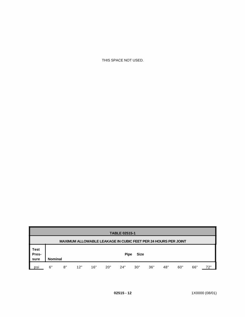
02515 - 12 1X0000 (08/01)
THIS SPACE NOT USED.
TABLE 02515-1
MAXIMUM ALLOWABLE LEAKAGE IN CUBIC FEET PER 24 HOURS PER JOINT
TestPres-sure
Nominal
Pipe Size
psi 6" 8" 12" 16" 20" 24" 30" 36" 48" 60" 66" 72"
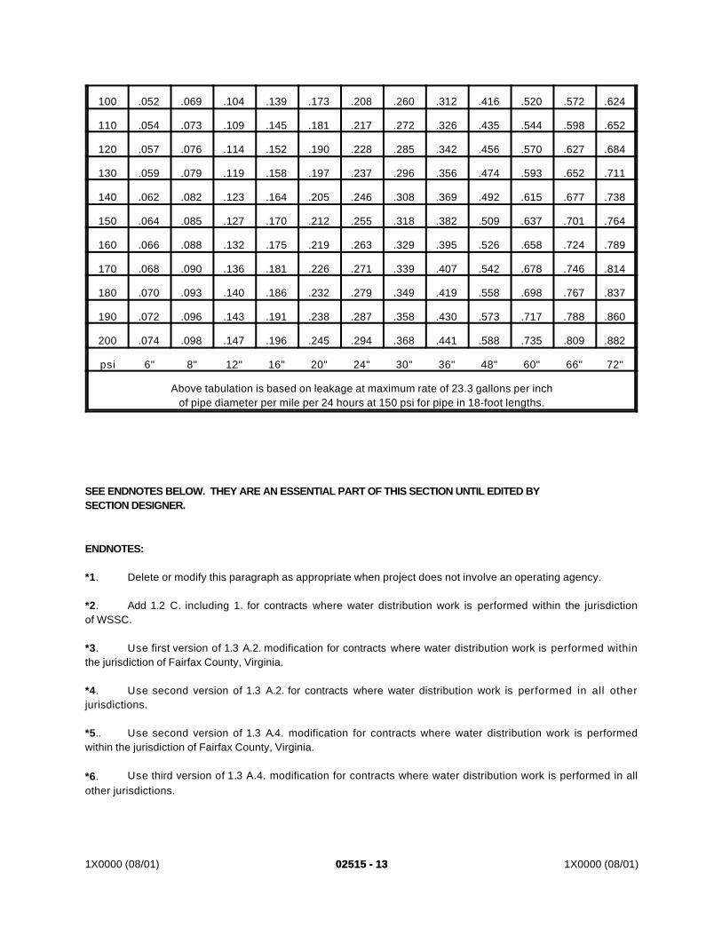
1X0000 (08/01) 02515 - 1302515 - 13 1X0000 (08/01)
*1. Delete or modify this paragraph as appropriate when project does not involve an operating agency.
*2. Add 1.2 C. including 1. for contracts where water distribution work is performed within the jurisdictionof WSSC.
*3. Use first version of 1.3 A.2. modification for contracts where water distribution work is performed withinthe jurisdiction of Fairfax County, Virginia.
*4. Use second version of 1.3 A.2. for contracts where water distribution work is performed in all otherjurisdictions.
*5.. Use second version of 1.3 A.4. modification for contracts where water distribution work is performedwithin the jurisdiction of Fairfax County, Virginia.
*6. Use third version of 1.3 A.4. modification for contracts where water distribution work is performed in allother jurisdictions.
100 .052 .069 .104 .139 .173 .208 .260 .312 .416 .520 .572 .624
110 .054 .073 .109 .145 .181 .217 .272 .326 .435 .544 .598 .652
120 .057 .076 .114 .152 .190 .228 .285 .342 .456 .570 .627 .684
130 .059 .079 .119 .158 .197 .237 .296 .356 .474 .593 .652 .711
140 .062 .082 .123 .164 .205 .246 .308 .369 .492 .615 .677 .738
150 .064 .085 .127 .170 .212 .255 .318 .382 .509 .637 .701 .764
160 .066 .088 .132 .175 .219 .263 .329 .395 .526 .658 .724 .789
170 .068 .090 .136 .181 .226 .271 .339 .407 .542 .678 .746 .814
180 .070 .093 .140 .186 .232 .279 .349 .419 .558 .698 .767 .837
190 .072 .096 .143 .191 .238 .287 .358 .430 .573 .717 .788 .860
200 .074 .098 .147 .196 .245 .294 .368 .441 .588 .735 .809 .882
psi 6" 8" 12" 16" 20" 24" 30" 36" 48" 60" 66" 72"
Above tabulation is based on leakage at maximum rate of 23.3 gallons per inchof pipe diameter per mile per 24 hours at 150 psi for pipe in 18-foot lengths.
SEE ENDNOTES BELOW. THEY ARE AN ESSENTIAL PART OF THIS SECTION UNTIL EDITED BYSECTION DESIGNER.
ENDNOTES:
02515 - 14 1X0000 (08/01)
*7. Add first version of 1.3 A.5. for contracts where water distribution work is performed within thejurisdiction of WSSC.
*8. Add second version of 1.3 A.5. for contracts where water distribution work is performed within thejurisdiction of Fairfax County, Virginia.
*9. Add 1.3 A.7. for contracts where water distribution work is performed within the jurisdiction of WSSC.
*10. Use second version of 2.1 R. for contracts where water distribution work is performed outside thejurisdiction of WSSC.
*11. Use first version of 2.1 S. including 1.a. modification for contracts where water distribution work isperformed within the jurisdiction of WSSC.
*12. Use second version of 2.1 S. for contracts where water distribution work is performed outside thejurisdiction of WSSC.
*13. Add 2.1 V. for contracts where water distribution work is performed within the jurisdiction of WSSC andwhere water distribution work is performed within the jurisdiction of Fairfax County, Virginia.
*14. Add first version of 2.1 W. for contracts where water distribution work is performed within the jurisdictionof WSSC.
*15. Add second version of 2.1 W. for contracts where water distribution work is performed within thejurisdiction of Fairfax County, Virginia.
*16. Add first version of 2.1 X. including 1.-7.e. for contracts where water distribution work is performedwithin the jurisdiction of WSSC.
*17. Add second version of 2.1 X. including 1.-3. for contracts where water distribution work is performedwithin the jurisdiction of Fairfax County, Virginia.
*18. Add first version of 2.1 Y. for contracts where water distribution work is performed within the jurisdictionof WSSC.
*19. Add second version of 2.1 Y. for contracts where water distribution work is performed within thejurisdiction of Fairfax County, Virginia.
*20. Add 2.1 Z. for contracts where water distribution work is performed within the jurisdiction of FairfaxCounty, Virginia.
*21. Add 3.5 G. for contracts where water distribution work is performed within the jurisdiction of FairfaxCounty, Virginia.
*22. Add 3.5 H. for contracts where water distribution work is performed within the jurisdiction of FairfaxCounty, Virginia.
*23. Add 3.5 I. for contracts where water distribution work is performed within the jurisdiction of FairfaxCounty, Virginia.
1X0000 (08/01) 02515 - 1502515 - 15 1X0000 (08/01)
*24. Add 3.5 J. for contracts where water distribution work is performed within the jurisdiction of FairfaxCounty, Virginia.
*25. Add 3.11 C. including 1.-2.c. for contracts where water distribution work is performed within thejurisdiction of WSSC.
*26. Use first version of 3.16 A. modification for contracts where water distribution work is performed withinthe jurisdiction of WSSC and where water distribution work is performed within the jurisdiction of Fairfax County,Virginia and Falls Church, Virginia.
*27. Use second version of 3.16 A. modification for contracts where water distribution work is performed inall other jurisdictions.
*28. Add 3.16 B. for contracts where water distribution work is performed within the jurisdiction of WSSCand where water distribution work is performed within the jurisdiction of Fairfax County, Virginia and FallsChurch, Virginia.
*29. Add first version of 3.16 C. where water distribution work is performed within the jurisdiction of FairfaxCounty, Virginia and Falls Church, Virginia.
*30. Add second version of 3.16 C. for contracts where water distribution work is performed within thejurisdiction of WSSC.
*31. Add 3.16 D. for contracts where water distribution work is performed within the jurisdiction of WSSC.
*32. Use first version of 3.19 A.1. modification for contracts where water distribution work is performed withinthe jurisdiction of WSSC.
*33. Use second version of 3.19 A.1. modification for all other contracts where water distribution work isperformed.
END OF SECTION
02460-2 1X0000 (08/01)
6. Production Maximum Tip Elevation: The elevation below which production pile tipsmust penetrate by at least one foot, based on the indicator pile test program.
7. Pile Design Load: The load each pile is designed to carry.8. Ultimate Bearing Capacity: The maximum bearing capacity that the pile can sustain
without rapid progressive settlement of the pile under constant load.
C. Pile Type:1. Prestressed precast concrete piles, driven.
D. Related Information:1. Grading, Excavating, and Backfilling: Section 02320.2. Support of Excavation: Section 02260.3. Concrete Formwork: Section 03100.4. Concrete Reinforcement: Section 03200.5. Cast-in-Place Structural Concrete: Section 03300.6. Structural Precast Concrete: Section 03400.7. Prestressed Concrete: Section 03415.
1.02 QUALITY ASSURANCE:
A. Codes, Regulations, Reference Standards and Specifications:1. Codes and regulations of the jurisdictional authorities.2. ASTM Standards:
a. D1143 - Test Method for Piles Under Static Axial Compressive Load.b. D4945 - Test Method for High Strain Dynamic Testing of Piles.
1.03 SUBMITTALS:
A. Submit the following for the Engineer’s approval in accordance with the GeneralRequirements and with the additional requirements as specified for each:1. Shop Drawings:
a. For Static Pile Load Tests, provide drawings that show load test apparatussetup including the method of applying the load. Drawings must showdevices to be used to measure pile top movement.
b. For Dynamic Pile Testing, provide manufacturer’s or vendor’s data ontransducers, computer, wiring, and schematic drawings for testing specifiedpiles.
c. For Static Pile Load Test and Dynamic Pile Testing programs, providedetailed sequence of testing, evaluation of results and planned reports.
d. Pile splicing is not desired and shall be avoided. In the event that concretepiles are driven below the elevation of bottom of cap, build-ups, precast orcast-in-place splicing may be used when approved by the Engineer. The pilesubmittal shall include splice details, build-up details and any other detailsnecessary to satisfy the requirements of these specifications.
e. The pile submittal shall show prestressing methods, tendon arrangement,working stresses, and methods for pick-up and handling of piles.
f. Submit certification of accuracy for all gauges and test equipment.2. Documentation:
a. Driving Equipment/Accessories List:1) Submit details of proposed driving equipment to include cranes,
leads, hammer, compressors, powerpacks, driving caps, hammercushions and pile cushions. Data on hammer shall include as aminimum the manufacturer’s model number, estimate of efficiency,
02460 - 3 1X0000 (08/01)
energy ratings and ram details, including operation certificationperformed within the last 90 days.
2) Submit details of accessory equipment to be used including servicecranes, hoses, throttles, and pile handling rigging.
b. Submit procedures and details for installation of reinforcement andprestressing.
c. Submit materials certifications and concrete mix designs for all concreteproducts to be used during the pile installation.
d. Indicator Pile Order List:1) Submit a list of piles to be installed as part of the indicator pile test
program. List shall show type, size, number, location, indicator pileorder length, predicted maximum tip elevation, allowable drivingstress related to hammer blows, and blow count needed to attaintwice the pile design load. If locations for indicator piles differ fromthose shown on the drawings, provide reasons for change. Theproposed revised location will be reviewed and, if appropriate,approved by the Engineer.
2) Submit list prior to ordering indicator piles.e. Test Documentation and Reports:
1) The Contractor shall retain an experienced Engineer employed bya Dynamic Testing Consultant. The Dynamic Testing Consultant’sEngineer shall be an integral part of the Contractor’s Quality ControlProgram. Submit the qualifications of the Dynamic TestingConsultant’s Registered Maryland Professional Engineerresponsible for monitoring Static and Dynamic Pile Testing. TheDynamic Testing Consultant’s Engineer shall have a minimum offive (5) years experience in similar work, of which two (2) yearsshall be field experience with the monitoring of pile drivingoperations. The Dynamic Testing Consultant shall provide thefollowing:a) Results of all Wave Equation Analyses using the
GRLWEAP program, Dynamic tests, Static tests and theCase Pile Wave Analysis Program (CAPWAP). TheGRLWEAP and CAPWAP program is a product of GlobleRausche Likins and Associates, Inc., 4535 RenaissanceParkway, Cleveland, OH 44128. Telephone (216)831-6131.
2) Sample pile driving record/report and sample sketch proposed toshow any necessary deviations from planned locations.
3) An annotated sample of the dynamic testing apparatus output.Output shall include recorded input, reduced data and analysis.
4) After completion of each Static and/or Dynamic Pile Test, submit atest report for review and approval by the Engineer. The test reportshall include reporting information specified in ASTM D1143 andD4945, results of the refined wave equation analyses, andrecommendations for the Production Pile Order List.
5) Prepare a summary report of all the wave equation analyses,CAPWAP, and results of the dynamic and static pile tests. Thereport shall include test details, hammer and driving system details,soil conditions, instrumentation, test sequence and observations,discussions of test results (including hammer performance, drivingstresses, pile integrity and pile capacity), and conclusions andrecommendations for the Production Pile Order List.
f. Production Pile Order List:
02460-4 1X0000 (08/01)
1) After review and approval of the results of the Static Pile Load Testand Dynamic Pile Testing, submit an “Order List” of production pilesproposed to be installed in each pile group. The list shall showtype, size, number, location, sequence of installation, length,production maximum tip elevation , allowable driving stress relatedto hammer blows and blow count needed based on end of initialdriving results to attain twice the pile design load for all piles in eachpile group.
g. Pile Driving Record:1) Maintain a record throughout the indicator pile test program and
production pile driving operations and submit to the Engineer uponcompletion of each pile group. The record shall show theapplicable established driving criteria developed by the Static LoadTest, as modified by Dynamic Testing, for each pile. As a minimuminclude the following information:a) Sequence in which piles were driven.b) Equipment: type, model, serial number.c) Required blow count per approved driving criteria,
allowable driving stress related to hammer blows,production maximum tip elevation and final pile tipelevation.
d) Blow count for each foot of driven length.e) For all piles, the number of blows per inch of penetration
for last 12 inches.f) Unusual conditions encountered during driving of each pile.
g) Immediately after final pile driving, record top elevation ofpile to nearest 0.01 inch. Provide as built pile informationafter all piles in a pile group have been driven.
1.04 PRODUCT DELIVERY AND HANDLING:
A. Lifting loops shall be used as provided by the precaster. Lifting loops shall not be tied in anyway to the pile reinforcement. Loops may remain in place during driving. When handling anddelivering precast piles, avoid bending and breaking or chipping of piles.
PART 2 - PRODUCTS
2.01 MATERIALS:
A. Precast concrete piles:1. Prestressed precast concrete piles in accordance with Sections 03100, 03200,
03300, 03400, and 03415 of these specifications as applicable, shaped as shown.
B. Miscellaneous Driving Accessories: Including driving heads, collars, bands, shoes, and otherdriving devices in accordance with pile manufacturer’s recommendations.
C. Lean concrete: Section 02260.
02460 - 5 1X0000 (08/01)
PART 3 - EXECUTION
3.01 DRIVING EQUIPMENT:
A. The Engineer will review submitted data on driving equipment, accessories and methods foradequacy in conditions expected.
B. Adequacy of equipment and accessories remains the responsibility of the Contractor.
C. Should the equipment used by the Contractor prove inadequate to drive scheduled types ofpiles at the locations shown, or should progress schedule not be maintained, the Engineermay require replacement of equipment or different expendable accessories or additionalequipment.
D. If the hammer, driving block, cushion or any other part of the driving system is changed forany reason, the system must be calibrated by conducting Dynamic Pile Testing to prove thenew system is equal to the original system. This work shall be made at no additional time tothe Contract and at no cost to the Authority.
3.02 INDICATOR PILE TEST PROGRAM:
A. Installation:1. No later than twenty-one (21) days prior to driving indicator piles, conduct initial wave
equation analysis that represents the subsurface conditions on this project, the pileproperties and driving equipment provided. This analysis shall be submitted alongwith the required pile and driving equipment data to the Engineer.
2. Provide and install indicator piles where shown, to determine lengths of productionpiles to be furnished to achieve twice the pile design load in the scheduled pilegroups. If twice the design load is not attained when the top of the pile is one-footabove planned cut off, discontinue driving for a period of 24 hours or as directed bythe Engineer. After the specified period, restrike pile in accordance with Article3.2.B.1.b. If twice the design load is not attained after restrike, splice the pile, ifnecessary, and drive it until the specified bearing value is obtained.
3. Locate piles at contract pile locations so they can become part of the completedstructure provided they are approved as conforming to requirements specified forproduction piles. Install indicator piles to achieve pile tips below the predictedmaximum tip elevation, in the presence of the Engineer. Assist the Engineer inverifying measurements and driving characteristics as necessary to evaluate theadequacy of the foundation system.
4. The indicator piles scheduled for Static Pile Load Tests are shown on the ContractDrawings. The Engineer may designate alternate or additional indicator piles thatexhibit the weakest bearing capacity for Static Pile Load Tests.
5. Piles which are subjected to Static Pile Load Tests which do not pass theacceptance requirements shall be restruck, per 3.2. B.1.b with Dynamic TestingApparatus installed and functioning, within 48 hours after completion of the StaticPile Load Test to reestablish the minimum required pile length and blow counts.
6. Additional piles may be driven, at the Contractor’s option, in the area of the StaticLoad Test Piles to be used as reaction piles. All piles driven as indicator piles orreaction piles for load tests in accordance with the plans and specifications andmeeting specified requirements for production piles can, upon approval, be cut offand become a part of the permanent structure.
7. Install all indicator piles that are intended to become part of the permanent structurewith the same type and model of equipment and methods to be used to installproduction piles. Perform work in the presence of the Engineer.
02460-6 1X0000 (08/01)
8. Remove piles which are not incorporated into the completed structure or which donot satisfy test requirements. Alternatively, if rejected piles are not removed then cutoff at least three (3) feet below finished grade and backfill resulting hole with leanconcrete.
B. Pile Testing:1. Dynamic Pile Testing:
a. Perform Dynamic Pile Testing in accordance with ASTM D4945.b. Install indicator piles where shown with the Dynamic Testing Apparatus
installed and functioning to measure performance of the driving system andthe bearing capacity. Begin dynamic testing during initial driving when thepile tip achieves the predicted maximum tip elevation. Drive indicator pilesto a bearing capacity of at least twice the pile design load based on initialdriving. Restrike all indicator piles, with Dynamic Testing Apparatusinstalled and functioning to verify results from initial driving of these piles.Restrike indicator piles with the hammer at normal operating temperaturefor a maximum penetration of twelve inches, a maximum of 60 hammerblows, or to less than the driving stress limits established by Article 3.3.B,whichever occurs first. Pile driving shall resume as if it was the initial strikeconditions per Article 1.1.A.1.c to obtain the correct pile driving criteria
c. Perform CAPWAP analyses using the Dynamic Pile Testing data from theend of initial driving and the beginning of restrike of all indicator piles.
d. Perform refined wave equation analyses using the dynamic test results ofeach indicator pile. Incorporate the results of the refined wave equationanalyses in driving of subsequent indicator piles. Refined wave equationanalyses shall be based upon the variations in the subsurface conditionsand/or drive system performance measured by the dynamic testingapparatus.
2. Static Pile Load Tests:a. Static Pile Load Test equipment and testing procedures shall be in
accordance with ASTM D1143, Quick Load Test Method, except asmodified herein.
b. Provide test equipment with capacity greater than three times the pile designload and having means of determining applied load to within five (5) percentof test load. Provide test equipment capable of measuring total settlementat the top of the pile to nearest 0.001 inch.
c. Perform Static Pile Load Tests. Commence loading the pile no sooner than72 hours after installation of the pile. The maximum test load shall be equalto three times the pile design load or the ultimate bearing capacity,whichever occurs first.
d. The ultimate bearing capacity under axial comprehensive load is that loadwhich produces a settlement of the pile head equal to:Su=S+(0.15+0.008D)Where:Su= Settlement at ultimate bearing capacity in inchesS = Elastic deformation of total unsupported pile length in inchesD = Pile diameter or width in inches
e. The safe bearing capacity is defined as 50 percent of the maximum testload. Static load test results will be acceptable when the safe bearingcapacity equals or exceeds the design bearing capacity.
02460 - 7 1X0000 (08/01)
f. Restrike piles for monitoring with Dynamic Testing Apparatus inaccordance with Articles 3.2.A.5 and 3.2.B.1.
3.03 PRODUCTION PILE DRIVING:
A. Bearing Value, Length and Penetration:1. Provide production piles of length necessary to attain production maximum tip
elevation, twice the pile design load, and to extend into cap or footing block asshown.
2. Determine lengths of production piles by analysis of data obtained from Static PileLoad Tests, Dynamic Pile Testing and refined wave equation analyses.
3. Any pile that does not reach twice the pile design load by approved blow count orattain the minimum penetration will be rejected. Rejected piles will be restruck after48 hours in accordance with Article 3.2.B.1 and ,if necessary tested using DynamicPile Testing equipment as directed by the Engineer to prove attained capacity at noadditional cost to the Authority.
4. The Contractor may install additional test piles, make borings or make such otherinvestigations as he may desire at no additional time to the Contract and no cost tothe Authority.
B. Pile Driving Stresses:1. Indicator and production piles shall not be driven above the hammer energy and
blow count shown by the wave equation analyses to produce stresses above thepoint of impending damage. For concrete piles limit the tensile (TS) andcompressive (CS) driving stresses to:
TS £ 3Ö fc’ + EPV
CS £ 0.85 fc’ - EPWhere:
fc’ = The 28-day design compressive strength of the concreteEPV = The effective prestress value
2. Cut off grade: At the Contractor’s option, production piles reaching design bearingcapacity and production maximum tip elevation with tops above the cut off grademay be driven to the cut off grade providing the required bearing capacity ismaintained, allowable driving stresses within the pile have not been exceeded andno damage to the pile occurs. Piles damaged or suspected of damage due todriving to achieve a cut off grade shall be pulled and/or replaced at the Contractor’sexpense.
C. General Requirements:1. Drive piles only after completion of required excavation or construction of indicated
embankments.2. Stage driving within supported excavation areas so as not to damage internal
bracing.3. For production piles in permanent embankments, pre-drill through fill or embankment
to natural ground or bottom of embankment.4. Drive each pile in a continuous operation until required penetration and twice the pile
design load have been attained. If driving is stopped before required blow count andpenetration have been reached, drive the pile one foot upon resumption of drivingbefore resuming blow count for bearing value determination.
5. Redrive each pile which is lifted 1/4 inch or more by ground heave during driving ofadjacent piles to at least the original tip elevation or as directed.
02460-8 1X0000 (08/01)
6. Remove loose and displaced material forced up around piles during driving.7. In Terrace deposits and directly above the Monmouth Formation, cobbles, boulders
and cemented sand/silt deposits were found. Penetrate into and through thesedeposits as necessary to attain twice the pile design load and required maximum tipelevation.
8. Achieve pile penetration through miscellaneous fill, rubble concrete, tires, hardpan,cemented sands/silts, and any other obstruction, natural or man-made, by meansof pre-drilling or other approved excavation methods.
9. Hold pile tops in position with steel driving block or anvil.10. Do not drive piles with free swinging hammer.11. Pull and replace piles which are not within specified tolerances or, if approved,
redesign pile cap as specified. Costs associated with the redesign and constructionof modified pile caps will be borne by the Contractor and no additional time to theContract will be allowed.
D. Pre-drilled Holes:1. Where shown on the Contract Drawings, drill holes to diameter of greatest cross
section dimension of the pile to be installed in accordance with the notes andschedules on the drawings and with Section 204.
2. Set pile in pre-drilled hole and drive to predicted or production maximum tip elevationand twice the pile design load, but in all cases to a minimum depth of five (5) feetbelow bottom of pre-drilled hole.
3. Fill voids between pre-drilled hole and pile with lean concrete immediately uponcompletion of the driving sequence, as approved.
4. Dispose of material resulting from drilling holes in accordance with the requirementsof Section 204.
5. Fill rejected pre-drilled holes with lean concrete and redrill at approved location.
E. Concrete Piles:1. Cut off piles at such elevation that they will extend into cap or footing as shown. Saw
cut piles with equipment capable of providing a flat smooth surface without spallingor damaging pile below cutoff. Replace or repair piles that are damaged when cutoff.
2. Where reinforcing steel dowels are shown, dowels may be anchored in cast or drilledholes in concrete pile. If holes are drilled, drill by methods that will not damageconcrete, reinforcing steel or prestressing steel. Drill minimum diameter consistentwith placing approved epoxy adhesive and dowel. Leave holes free of dust, moistureor other deleterious material. Place sufficient epoxy in holes before inserting dowelsleaving no voids afterwards. Leave dowels undisturbed until epoxy has developed100 percent of its strength capacity.
3.04 FIELD QUALITY CONTROL:
A. Concrete Pile Allowable Tolerances:1. Ensure straightness and cross-sectional dimensions of precast piles so that a line
stretched from butt to tip on any face is not more than one inch from face of pile atany point.
2. Install piles within the following tolerances:a. Axis of pile within six inches of design location at cutoff elevation. b. Axis of pile not out of plumb or batter by more than one percent of its driven
length.c. No encroachment of piles upon neat lines of Authority structures.
02460 - 9 1X0000 (08/01)
PART 4 - MEASUREMENT AND PAYMENT
4.01 BASIS:
A. Compensation for work specified in this section will be made in the following manner:1. Furnishing and installing piles: Linear foot in place in the completed work measured
from the tip of the pile to the plane of the cut off (top of pile). This price shall includeconducting and reporting the initial wave equation analysis, furnishing piles; drivingpiles; splices; concreting; achieving specified load and tip elevations.
2. Static Pile Load Test: This work will be measured and paid for at the Contract unitprice per each static pile load test performed. The payment will be fullcompensation for furnishing and setup of test equipment, providing reaction piles,conducting test, reporting and incidentals necessary to complete the work. If loadtest is terminated by the Engineer because of insufficient bearing capacity, test willbe measured for payment. If the test is terminated because of malfunction ofContractor’s equipment or other reasons that are the fault of the Contractor, the testwill not be measured for payment.
3. Dynamic Pile Testing: This work will be measured and paid for at the Contract unitprice per dynamic test performed. The payment will be full compensation forfurnishing and setup of dynamic testing equipment and conducting test during initialand restrike driving of each indicator pile, performing CAPWAP analyses, performingthe refined Wave Equation Analysis, reporting and incidentals necessary to completethe work. Incomplete tests and terminations treated in accordance with Article 4.A.2.
4. Pile restrike: This work will be measured and paid for at the Contract unit price, pereach restrike performed. The payment will be full compensation for furnishing andsetup of pile driving equipment required for restriking piles with dynamic equipmentinstalled and functioning in accordance with Article 3.2. If test is terminated byEngineer because of insufficient bearing capacity pile restrike will be measured forpayment. If the test is terminated because of malfunction of Contractor’s equipmentor other reasons that are the fault of the Contractor, pile restrike will not bemeasured for payment.
5. Pre-drilled holes shown and specified in Article 3.3 will be paid for at the Contractunit price per linear foot measured from the plane of the cut off (top of pile) to thelevel of the pre-drilled elevation specified. This price shall include providing theequipment, material and labor necessary to drill holes to the scheduled elevation,disposal of materials, placing lean concrete and incidentals necessary to completethe work.
END OF SECTION
1X0000 (03/03) 02535-1
SECTION 02535
SANITARY SEWER
PART 1 - GENERAL
1.01 DESCRIPTION:
A. This section specifies installing sanitary sewers.
B. Related Work Specified Elsewhere:1. Grading, excavating and backfilling: Section 02320.2. Maintenance, support and restoration of utility facilities: Section 02270.3. Stray current and cathodic protection: Section 13110 and 13115.
C. Material Furnished By Others: *11. Except for those items which bear the METRO logo, WSSC furnishes the
following:a. Manhole frames and covers: 22-inch diameter.b. Manhole steps, except where precast manholes are used.
D. Definitions: *21. Granular bedding required by WSSC is equivalent to aggregate for pipe cradle as
specified.2. WSSC: Washington Suburban Sanitary Commission.3. WASA: Water and Sewer Authority.
1.02 SUBMITTALS:
A. Submit the following for approval in accordance with the General Requirements and withthe additional requirements as specified for each:1. Shop Drawings:
a. Drawings for each size and configuration of precast manhole with detailsof accessories and joints.
b. Diagrams showing dimensioned locations for openings in precastconcrete manhole walls.
2. Documentation:a. Submit calculations for modified or special designs to demonstrate
compliance with required load-bearing capacity, certified by aprofessional engineer registered in the jurisdiction where the work is to beinstalled.
3. Samples:a. Sewer brick: Ten.b. Manhole brick: Ten.
4. Certification.5. Documentation: *3
a. Submit two copies of records of inspection of new and relocated sewers,one copy to WSSC and one copy to the Engineer. Include video-tapecassette of television inspections and logs, photographs and otherrecords specified by WASA for visual walk-through inspections.
b. Obtain and submit a written approval and acceptance from WASA.
1.03 QUALITY ASSURANCE:
02535-2 1X0000 (03/03)
A. Codes, Regulations, Reference Standards and Specifications:1. Comply with codes and regulations of the jurisdictional authorities.2. Building Stone Institute: Stone Catalog3. CISPI: HSN 85.4. AASHTO: M33, M153, T85, T96, T104. *45. AASHTO: H20, M33, M36, M153, M175, M176, M190, M252, M288, T85, T96,
T104. *56. ANSI/ASME: B16.1. *67. ACI: 318. 8. ASTM: A36, A48, A53, A74, A167, C14, C32, C33, C76, C144, C150, C207,
C361, C425, C443, C478, C700, D698, D1682, D3034. *79. ASTM: A36, A48, A53, A74, A167, C14, C32, C33, C76, C144, C150, C207,
C361, C425, C443, C478, C700, D698, D3034, D5034. D5035. *810. MS: MIL-P-23236.11. SSPC: SP-6.12. WSSC: General Conditions and Standard Specifications. *9
B. Allowable Tolerances:1. Rate of infiltration into sanitary sewer lines not to exceed 100 gallons per inch
diameter per 24 hours per mile of sewer.2. Subgrade: Plus-or-minus 1/2 inch of elevation shown.
C. Inspection: *10
1. Prior to paving or other construction over new or relocated sewers, conduct visualwalk-through inspection of sewers larger than 36 inches in diameter and ofassociated structures and internal television inspection of sewers 36 inches andsmaller in diameter.
2. Employ the services of a sewer inspection company which has been regularlyengaged in television sewer inspections and which is acceptable to WASA toperform preconstruction and post-construction inspections of sewers 36 inchesand smaller in diameter.a. Submit to WASA for prior approval one sample of the cassettes to be
used.
PART 2 - PRODUCTS
2.01 MATERIALS:
A. Formwork: Section 03100.
B. Reinforcing Steel: Section 03200.
C. Portland Cement Concrete: Section 03300, Class 3500, unless otherwise shown.
D. Aggregate for Subgrade Foundation: ASTM C33, coarse aggregate, No. 4. Whereshown use layers of No. 4 and No. 67 in combinations and proportions determined byfield conditions and as approved.
E. Aggregate for Pipe Cradle: ASTM C33, coarse aggregate No. 67.
F. Concrete Pipe:1. 10-inch diameter and smaller:
a. STM C14, Class 2, nonreinforced concrete pipe.b. Bell-and-spigot type.
1X0000 (03/03) 02535-3
c. Joints fabricated in accordance with ASTM C361. Physicalcharacteristics for rubber gaskets in accordance with ASTM C443.
2. 12-inch diameter and larger:a. ASTM C76, bell-and-spigot or tongue-and-groove, Class IV, unless
otherwise shown.b. Radius (bevel) pipe, with drop between two pipe sections not exceeding
the common wall thickness.c. Rubber gasket joints, when required, fabricated in accordance with
ASTM C361. Physical characteristics for rubber gaskets in accordancewith ASTM C443.
d. Acceptance tests as specified in ASTM C76 form basis of acceptance forconcrete pipe in accordance with the following:1) 72-inch diameter and smaller: Acceptance on the Basis of Plant
Load Bearing Test, Material Tests and Inspection ofManufactured Pipe for Visual Defects and Imperfections.
2) Larger than 72 inches in diameter: Acceptance on the Basis ofMaterial Tests and Inspection of Manufactured Pipe for Defectsand Imperfections.
3) Minimum laying lengths:(a) Sanitary sewer and combined system construction:(b) 72-inch diameter and smaller: Eight feet.(c) Larger than 72-inch diameter: Six feet.
e. Rubber gaskets: ASTM C361. *11
f. Rubber gaskets: ASTM C443. *12
g. Jointing mastic: Elastic, water-resistant, formulation of plastic bituminousmaterials, nonflammable solvent and inert fillers so combined that:1) When applied to a vertical metal surface and heated to 120F,
jointing mastic will neither slump nor lose plasticity.2) When applied directly from container without further fixing,
jointing mastic can be applied in even, adherent coat withintemperature range of 20F to 100F.
G. Plastic Pipe:1. Polyvinyl chloride (PVC) pipe: ASTM D3034, SDR-35.
H. Vitrified Clay Pipe: ASTM C700; Joints, ASTM C425, using plastic materials.
I. Cast-Iron Soil Pipe and Fittings: ASTM A74, extra-heavy (XH), with hub and spigot endsso constructed that joints may be made with gaskets conforming to CISPI DesignationHSN 85 and the requirements of the relevant plumbing codes.
J. Lubricant for Rubber Gasket Pipe Joints: Vegetable oil soap.
K. Mortar Materials:1. Portland cement: ASTM C150, Type I.2. Sand: ASTM C144, natural sand.3. Lime: Pressure-hydrated, ASTM C207, Type S.4. Water: Potable.5. Pigment: As approved.
L. Brick: ASTM C32; solid brick; Grade MS for manhole brick, Grade SS for sewer brick; 2-1/4 inches by 3-3/4 inches by eight inches.
M. Precast Concrete Manhole Sections: *13
1. ASTM C478.2. Joint entry seal gasket: A-LOK as manufactured by Atlantic Precast Concrete,
Inc.; A-LOCK gaskets, manufactured by A-LOK Products Corporation, Trenton,
02535-4 1X0000 (03/03)
N.J.; DURAC-SEAL gaskets, manufactured by DURA-CRETE, Inc., Dayton,Ohio; or equal.
N. Precast Concrete Manholes: *14
1. Cylindrical, eccentrical and conical: ASTM C478.2. Other configurations: ACI 318, AASHTO H20.
O. Manhole Steps:1. Cast iron: ASTM A48 Class 30 A.2. Rebar: No. 4 reinforcing bar with molded polypropelene or rubber encasement.
P. Manhole Frame and Cover; And Other Castings For Service With Utility Systems:1. Authority manhole: Cast-iron, ASTM A48, Class 30, with METRO logo. 2. Utility company manhole: Manhole frame and cover furnished as part of the
Contract or furnished by the utility as shown on the drawings.3. Rust-resistant cast iron or rust-resistant malleable cast iron.4. True to pattern in form and dimensions, free from pouring faults, sponginess,
cracks, blowholes and defects affecting strength.5. Fillets at angles in casting with arises sharp and perfect.6. Sandblasted to effectively remove scale and sand, presenting smooth, clean and
uniform surfaces. Coated with bituminous coating.7. Metro logo: For utility components which will remain METRO property and are
not within boundaries of utility easements as shown: Cast METRO logo asshown.
8. Covers that receive paver tile:a. Omit bituminous coating.b. Provide positioning lug and lug receptor as a permanent part of the cover
and frame rim so that the cover can only be installed (flush) in oneposition.
Q. Metal Water Seals for Basin Connections: Neenah Foundry Model No. R-3707 or equal.
R. Structural Steel Members: ASTM A36.
S. Steel Pipe: ASTM A53, black finish, extra strong wall class.
T. Stainless Steel Angle: ASTM A167, Type 304.
U. Jute for Caulking: Good quality jute, free from tar, oil, or grease and dry when installed.
V. Preformed Expansion Joint Fillers: AASHTO M153, Type I, Type II or Type III.
W. Bituminous Expansion Joint Filler: AASHTO M33.
X. Galvanizing: Section 05120.
Y. Miscellaneous Metal: Section 05500.
Z. Coal-Tar Epoxy Coating:1. Two-component.2. Chemically cured. 3. Conforming to MS MIL-P-23236 (Ships), Type I, Class 2.4. Thinner: As recommended by manufacturer of coating and as approved.
AA. Pipe Supports: *15
1. Pipe: Three-inch diameter, ASTM A53, Weight B, Class 1.
1X0000 (03/03) 02535-5
2. Flanges: ANSI/ASME B16.1, 125-pound Class, galvanized after fabrication.
2.02 MORTAR AND GROUT MIXES:
A. General Requirements:1. Mix dry in specified proportions by volume. Control and maintain accurate
measurement throughout progress of work.2. Add sufficient water as specified to produce approved consistency.3. Do not mix in amount exceeding that which can be used within one hour after
introduction of water.4. Do not retemper mix that has begun to set nor use such mix in the work.5. Where shown, specified or directed, mix pigment into dry mix to attain color
selected by the Engineer. Pigment not to exceed 10 percent of dry batch weightof cement.
B. Proportions:1. Mortar: One part portland cement, 2-1/2 parts sand and water sufficient to
produce stiff workable mix.2. Grout: One part portland cement, 2-1/2 parts sand and water sufficient to
produce plastic flowable mix.3. Mortar for setting and pointing granite: One part portland cement, four to five
parts sand, one part lime and water sufficient to produce approved consistency.4. Mortar for setting granite paving and grouted granite blocks: One part portland
cement, four parts sand, with water sufficient to produce approved consistency.
PART 3 - EXECUTION
3.01 EXCAVATION FOR SEWER:
A. Perform excavation for sewers line and grade shown in accordance with Section 02320and the following additional requirements:1. Excavate test pits sufficiently in advance of construction of sewers so that
reasonable changes in line and grade can be made where location of existingstructures varies from that shown.
2. Excavate below horizontal plane extending two feet above top of sewer tomaximum width of trench pay width shown. Where dimensions are not shown,make maximum horizontal width of excavation 18 inches from outside of sewerand minimum six inches. Where approved, excavation above such plane mayexceed specified dimensions.
3. If excavation exceeds permissible dimensions, encase pipe or install pipe ofhigher strength.
4. Where necessary to place backfill or embankment so that trench can beexcavated, extend backfill or embankment full depth laterally at least 2-1/2 timesdiameter of pipe on each side measured from centerline of pipe.
3.02 PIPE CRADLE:
A. Place pipes on cradle of aggregate or concrete where shown.
B. Place aggregate so as to avoid segregation; compact to maximum practicable density sothat pipe can be laid to required tolerances.
3.03 LAYING PIPE:
A. General Requirements:
02535-6 1X0000 (03/03)
1. Excavate to lines and grades shown in accordance with Sections 02320 andherein. Excavate depressions for bells.
2. Protect pipe and fittings during handling to prevent damage.3. Place, shape and compact bedding material to receive barrel of pipe. Type and
thickness of bedding material as shown.4. Start laying pipe at lowest point; lay true to line and grade shown.5. Install pipe to bear on bedding material along entire length. Shape bedding
material to fit bells and flanges.6. Install pipe so that bells and grooves are on upstream end.7. Align each section of pipe with adjoining section with uniform annular space
between bell and spigot and so as to prevent sudden offsets in flow line.8. As each section of pipe is laid, place sufficient backfill to hold it firmly in place.9. Keep interior of sewer clean as work progresses. Where small pipe size makes
cleaning difficult, keep suitable swab or drag in pipe and pull through each jointimmediately after jointing is completed.
10. Keep trenches and excavations free of water during construction and untilbackfilled. Each day, excavate only as much trench as needed to lay pipe.
11. When work is not in progress, securely plug ends of pipe and fittings to preventtrench water or other substances from entering pipes and fittings.
12. Where length of stub is not shown, install four-foot length and seal free end withbrick masonry bulkhead or approved stopper.
13. Have work approved prior to covering pipe.14. Where shown, place additional aggregate filter around and over pipe in lifts not
exceeding six inches loose. Compact each lift before placement of next lift.15. Backfill in accordance with Section 02320.16. Accomplish compaction by method that will avoid damage to pipe and will not
disturb its alignment and grade. The use of vibratory rollers is prohibited untilcompacted cover over pipe has reached three feet or half the pipe diameter,whichever is greater.
17. Where cathodic protection is shown, apply coal-tar epoxy coating.
B. Vitrified Clay Pipe:1. Nonperforated pipe:
a. Use pipe hoist, crane or other approved device when laying pipe greaterthan 18 inches diameter.
b. Prevent damage to premolded joint rings or attached couplings.c. Clean joint contact surfaces immediately prior to jointing. To complete
joint, use lubricants, primers or adhesives as recommended by pipe orjoint manufacturer.
C. Concrete Pipe:a. Bell-and-spigot joints:b. Lay bell-and-spigot joint pipe as specified for vitrified clay pipe.
1. Tongue-and-groove joints:a. Clean groove end of preceding pipe with wet brush and apply soft mortar
to lower 1/4 of groove. Clean tongue end of succeeding pipe with wetbrush and position it. Remove mortar from interior surface if squeezedout of joint.
b. Complete mortaring interior and exterior portions of joint for entirecircumference, extending from previously placed mortar. Perform finalexterior mortaring of joints three lengths of pipe behind laying.
D. Plastic Pipe:1. Nonperforated pipe:2. Join sections of pipe with couplings recommended by pipe manufacturer.
1X0000 (03/03) 02535-7
E. Inspections Of Sewers: *16
1. Perform all work in accordance with current requirements of WASA.2. Perform inspections on new or relocated storm, sanitary and combined sewers
within or adjacent to the zone of influence, as defined by the limits of a theoreticalslope of 1:1 from the bottom edges of tunneling and cut-and-cover excavations,as follows:a. Make inspections upon completion of tunneling and cut-and-cover
operations, but prior to paving.b. Obtain video-tape television inspection records of sewers 36 inches and
smaller in diameter.c. By means of visual walk-through inspection, obtain coordinated logs,
photographs and other records specified by WASA sewers larger than 36inches in diameter and of associated structures.
3. Coordinate all television and walk-through inspection field operations with WASA. All such work to be performed in the presence of a WASA representative.
3.02 BACKFILL:
A. Perform backfilling only after inspection and approval of pipe laying.
B. On completion of construction, backfill excavation in accordance with Section 02320.
3.03 JOINTS FOR COMBINED SEWER SYSTEM CONCRETE PIPE:
A. Use rubber gasket and bell-and-spigot pipe as specified.
B. Prior to jointing pipe, liberally coat pipe joints with lubricant.
C. Fit bell or spigot with gasket in accordance with manufacturer's instructions.
D. Joint pipes with equipment designed for purpose.
E. Before joint is completely home, check position of gasket using suitable gauge. If gasketis found to be dislocated, repeat entire joining process using new gasket.
3.04 JOINTS FOR VITRIFIED CLAY PIPE:
A. Immediately before joining vitrified pipe, liberally coat bell with lubricant and fit spigot withgasket.
B. Join pipes using equipment designed for purpose.
3.05 JOINTS FOR CAST-IRON SOIL PIPE AND FITTINGS:
A. Immediately before joining cast-iron soil pipe and fittings, liberally coat hub with lubricantand fit spigot with pipes using equipment designed for purpose.
3.06 CONNECTIONS WITH EXISTING SEWERS:
A. Make connections with existing public sewers in accordance with requirements of thejurisdictional authority.
B. Connect house sewers in accordance with local plumbing code.
02535-8 1X0000 (03/03)
C. Connect house sewers by means of Y-branches. Approved cast-iron thimble may beused, provided it is bonded into sewer pipe wall with approved epoxy at manufacturer'splant.
D. Do not connect existing sewer to sewer under construction unless approved.
E. Do not connect sanitary sewers to the WSSC system until application for suchconnections has been approved by WSSC. *17
3.07 TUNNELING AND JACKING:
A. Perform tunneling and jacking by approved methods.
B. Where open cut is specified and the Engineer permits the work to be done by tunneling orjacking, perform such work as specified and as approved.
C. Cost of material substitutions required by change of methods will be borne by theContractor.
D. Make horizontal borings necessary to lay pipe lines true to line and grade.
E. When sewers are laid in borings, completely fill void between outside barrel of pipe andboring with cement grout pumped into place.
F. When drainage pipes are laid in borings, completely fill void between pipe and boring withsand, using water pressure to ensure that voids are filled.
G. Methods of boring and filling of voids between pipe and boring are subject to approval.
3.08 CAST-IN-PLACE CONCRETE CONSTRUCTION:
A. Conform to applicable requirements of Sections 03100, 03200 and 03300. Sectiondesigner to specify the type of cement to be used. The type of cement will varydepending upon the jurisdiction where the work is performed.1. Cement. *18
B. Construct concrete support systems where shown. Section designer to specify the typeof mortar to be used. Mortar type will vary depending upon jurisdiction in which the workis performed.1. Mortar and cement. *19
3.09 BRICK CONSTRUCTION:
A. Perform brick construction as specified in Section 04215, with the following additionalrequirements:1. Use sewer brick wherever brick construction is exposed to flow; otherwise, use
manhole brick.2. Lay sewer brick on edge so that 2-1/4 by 8-inch side is exposed to flow.3. Lay manhole brick so that every sixth course is a header course.4. Where practicable, lay each course with a line. For curved courses or those in
nonparallel planes, use bonded-and-keyed construction.5. Do not exceed joint thickness of 3/8 inch in straight courses in parallel planes; for
courses curved or in nonparallel planes, make thickest part of joint as thin aspracticable.
1X0000 (03/03) 02535-9
6. Rack or tooth uncompleted brick construction and parge unexposed surfaces with1/2 inch of mortar.
3.10 MANHOLES:
A. Construct manholes of precast sections, cast-in-place concrete or brick as shown.
B. Provide base of precast or cast-in-place construction. Make watertight connectionbetween base and risers.
C. Unless otherwise shown, place axes of manholes directly over centerlines of pipes.
D. Construct appropriate flow channels in bottom of manholes.
E. Where necessary, build connections for public and residential sewers into manholes. Cutpipe flush with inside wall of structure. Do not build pipe into wall; provide mortar jointbetween pipe and structure.
F. Install manhole steps and cast iron frame and cover for each manhole; adjust frame andcover to proper grade by brick construction.
G. Install joint entry seal gaskets in openings in the walls of 48-inch precast manholes withO-ring joint. *20
H.
3.11 COATING APPLICATION AND REPAIR:
A. Preparation of surface: Perform the following in order given:1. Clean surfaces contaminated with oil or grease using naphtha or xylol.2. Remove rust and mill scale from surfaces by dry abrasive blasting to commercial
finish in accordance with SSPC SP-6.3. Coat surfaces within 24 hours and before dew point is reached.4. Apply coating only to surfaces which are dry and free of contaminants. Whip
blast surfaces not coated within specified time limit.
B. Application of coating:1. Mix coating in quantity which can be applied within its pot life if in accordance with
manufacturer's recommendation. Thin only with approval.2. Apply coating to exterior surfaces of pipes and fittings in accordance with
recommendations of coating manufacturer and as follows:a. Two coats of equal thickness.b. Total dry film thickness: 20 mils.c. Pretreat first coat as required prior to application of second coat.d. Apply second coat before first coat has dried tack-free but not later than
24 hours after application of first coat, unless otherwise recommended bycoating manufacturer.
e. Inspect coating prior to burial. Repair damages in accordance withrecommendations for field corrections by coating manufacturer.
3. Test cathodic protection as specified in Section 13115.
3.12 FIELD QUALITY CONTROL:
A. Maximum Surface Variation Tolerances:1. Grouted riprap: 1-1/4 inches in four feet from true plane.2. Bituminous concrete: Plus-or-minus 1/4 inch from specified grade in 25 feet.
02535-10 1X0000 (03/03)
*1. Add 1.1 C. including 1.a.-b. for contracts where sanitary systems work is performed within thejurisdiction of WSSC.
3. Cast-in-place concrete: Plus-or-minus 1/4 inch from specified grade in 15 feet.4. Precast concrete block: Plus-or-minus 1/2 inch from specified grade in 25 feet.5. Paving brick: Plus-or-minus 1/2 inch from specified grade in 25 feet.
B. Leakage Tests:1. Perform leakage tests on sanitary sewer lines to verify compliance with allowable
tolerances specified.
C. Obstruction Tests:1. Perform field tests to verify that installed storm and sanitary systems are free
from obstructions.2. Remove obstructions by excavating at the apparent obstruction and repairing or
replacing the defective pipe as directed by the Engineer.
D. Low-Pressure Air Testing Of Sanitary Sewers. *21
1. Test sanitary sewers with air under low pressure in accordance with WSSCprocedures. The tests will not be accepted by the WSSC until the sewers meetthe criteria enumerated. Pressure gauges, stop watches and test supervision willbe provided by the WSSC. Provide air compressor, hose, plugs, labor and suchmaterials, equipment and assistance required to perform the tests. Conduct testsin the presence of representatives of the WSSC. Do not place air under pressurein any sewer under any condition except those specified by WSSC.
2. Inspect sanitary sewers, including manholes, prior to air testing. Prior toundertaking the low-pressure air tests, correct and eliminate any water leakageinto the system sufficient to constitute a noticeable trickle or dribble.
3. Wherever underdrains have been constructed or gravel placed under pipelines todewater the trench during construction of the sewers, do not make air test untilpumps used in the dewatering process have been removed from the site.
4. Before air tests are scheduled, complete backfill operations and compactiontests. Have compaction test approved before air tests are scheduled.
5. Schedule air tests with the WSSC at least 48 hours in advance. Test eachsection of completed sewers. Test sewers from manhole to manhole, or frommanhole to terminus of the sewer if there is not a manhole at the other extremity. Do not exclude any sewers or sewer connections from this testing procedure.
3.13 TRANSPORTATION AND INSTALLATION OF MATERIALS FURNISHED BY OTHERS: *22
A. Transport and install materials furnished at the WSSC's storeyard at Bladensburg or otherdelivery points designated by the WSSC.
B. Use only suitable equipment, tools, and appliances for the safe and convenient handlingand hauling of materials.
C. Check that all materials furnished by the WSSC are in satisfactory condition.
D. Materials damaged, lost or wasted after acceptance will be replaced by the WSSC at theexpense of the Contractor.
E. Material showing inherent defects will be replaced by the WSSC without charge.
SEE ENDNOTES BELOW. THEY ARE AN ESSENTIAL PART OF THIS SECTION UNTIL EDITED BYSECTION DESIGNER.
1X0000 (03/03) 02535-11
*2. Add 1.1 D. including 1. for contracts where sanitary systems work is performed within the jurisdictionof WSSC.
*3. Add 1.2 E. including 1.-2. for contracts where sanitary systems work is performed within thejurisdiction of WASA.
*4. Use first version of 1.3 A.4. modification for contracts where sanitary systems work is performed withinthe jurisdiction of WSSC.
*5. Use second version of 1.3 A.4. for contracts where sanitary systems work is performed outside thejurisdiction of WSSC.
*6. Use first version of 1.3 A.5. modification for contracts where sanitary systems work is performed withinthe jurisdiction of WSSC.
*7. Use first version of 1.3 A.6. modification for contracts where sanitary systems work is performed withinthe jurisdiction of WSSC.
*8. Use second version of 1.3 A.6. for contracts where sanitary systems work is performed outside thejurisdiction of WSSC.
*9. Add 1.3 A.9. for contracts where sanitary systems work is performed within the jurisdiction of WSSC.
*10. Add 1.3 C. including 1.-2.a. for contracts where sanitary systems work is performed within thejurisdiction of WSSC.
*11. Use first version of 2.1 F.2.f. modification for contracts where sanitary systems work is performedwithin the jurisdiction of WSSC.
*12. Use second version of 2.1 F.2.f. for contracts where sanitary systems work is performed outside thejurisdiction of WSSC.
*13. Use first version of 2.1 N. including 1.-2. modification for contracts where sanitary systems work isperformed within the jurisdiction of WSSC.
*14. Use second version of 2.1 N. including 1.-2. for contracts where sanitary systems work is performedoutside the jurisdiction of WSSC.
*15. Add 2.1 DD. including 1.-2. for contracts where sanitary systems work is performed within thejurisdiction of WSSC.
*16. Add 3.4 E. including 1.-3. for contracts where sanitary systems work is performed within thejurisdiction of WASA.
*17. Add 3.11 E. for contracts where sanitary systems work is performed within the jurisdiction of WSSC.
*18. Specify the type of cement to be used. The type of cement will vary depending on the jurisdiction andthe use of the sanitary system.
*19. Specify the type of mortar and cement to be used. They will vary depending on the jurisdiction andthe use of the sanitary system.
*20. Add 3.15 G. for contracts where work is performed within the jurisdiction of WSSC.

02535-12 1X0000 (03/03)
*21. Add 3.21 D. including 1.-5. for contracts where work is performed within the jurisdiction of WSSC.
*22. Add 3.22 including A.-E. for contracts where work is performed within the jurisdiction of WSSC.
END OF SECTION
1X0000 (03/03) 02585-1
SECTION 02585
UNDERGROUND ELECTRICAL ANDCOMMUNICATIONS DISTRIBUTION SYSTEMS
PART 1 - GENERAL
1.01 DESCRIPTION:
This section specifies providing new ducts, manholes and handholes for electrical andcommunications facilities.
A. Related Work Specified Elsewhere:1. Grading, excavating and backfilling: Section 02320.2. Support of excavation: Section 02260.3. Maintenance, support and restoration of utility facilities: Section 02270.4. Grounding and bonding: Section 16060.5. Concrete formwork: Section 03100.6. Concrete reinforcement: Section 03200.7. Cast-in-place structural concrete: Section 03300.8. Structural precast concrete: Section 03400.
B. Definitions:1. Conduit: Individual raceway.2. Ductbank: Assembly of conduits in configurations shown, with concrete
encasement, with or without reinforcement.
1.02 SUBMITTALS:
A. Submit the following for approval in accordance with the General Requirements and with theadditional requirements as specified for each:1. Shop Drawings:
a. Drawings for each cast-in-place manhole and handhole.b. Drawings for each size and configuration of precast manhole and handhole
with details of accessories and joints.c. Diagrams showing dimensioned locations for openings and knockout panels
for ductbank penetrations of manhole and handhole walls.2. Documentation:
a. Submit calculations to demonstrate compliance with required load-bearingcapacity, certified by a professional engineer registered in the jurisdictionwhere the work is to be installed.
1.03 QUALITY ASSURANCE:
A. Codes, Regulations, Reference Standards and Specifications:1. Comply with codes and regulations of the jurisdictional authorities.2. AASHTO: H15-44, H20-44.3. ANSI: C80.1.4. ASTM: A36, A48, A123, A185, A615, C33, C109, C173, C231, D570, D638, D790,
F512.5. NEMA: TC-14.6. UL: 6.
1.04 PRODUCT DELIVERY, STORAGE AND HANDLING:
02585-2 1X0000 (03/03)
A. Transport those materials supplied by utility companies from companies' storage facilities toconstruction site.
B. Protect materials stored on site from damage prior to incorporation into work and duringhandling.
1.05 JOB CONDITIONS:
A. Coordination with Utility Companies:1. Arrange with the Engineer to contact utility companies early enough to allow
sufficient time for them to accomplish work they are required to perform, givingspecial consideration to lead times required for cable work.
2. Establish liaison with utility companies furnishing materials for the work in order todetermine availability, locations, methods of storage and care of materials prior toincorporation into work.
PART 2 - PRODUCTS
2.01 MATERIALS:
A. Concrete Formwork: Section 03100.
B. Reinforcing Steel: Section 03200.
C. Concrete:1. Cast-in-place: Section 03300, Class 3500 or as required by the power company for
its facilities.2. Precast: Section 03400, Class 5000, unless otherwise shown on the drawings.
D. Materials Supplied by Utility Company: As listed.
E. Conduit and Fittings:1. PVC conduit and fittings: ASTM F512; modulus of elasticity, 500,000 psi.2. Concrete encased: Schedule 40.
a. Direct burial: Schedule 80 heavy wall.b. Solvent cement: As recommended by conduit manufacturer.
3. Galvanized rigid steel conduit and fittings: UL 6 and ANSI C80.1.4. Fiberglass conduit and fittings:
a. Rigid fiberglass reinforced epoxy conduit, UL 1684, IPS (Iron Pipe Size)based conduit.
b. Rigid fiberglass-reinforced epoxy, filament wound with minimum fiberglasscontent of 65 percent by weight and no fillers.
c. Type SW (Standard Wall) of IPS based standard conduit with nominal wallthickness of .09 inch for five-inch nominal conduit size, and nominal wallthickness of 0.07 inch for two through four-inch nominal conduit size.
d. Conduits, elbows and fittings manufactured from the same material andusing the same manufacturing process.
e. Conduit sections formed with integral bell-and-spigot type couplings.Rubber sealing gasket at bell end is prohibited.
f. Conduits, elbows and fittings shall be specified for use throughout atemperature range of -40°F to 230°F and protected from exposure tosunlight by pigmentation uniformly dispersed through resin material.
g. Adhesive as recommended by conduit manufacturer.h. Conduit, elbows and fittings shall be suitable for encasement in concrete
below grade and conform to UL 1684, and listed and labeled by UL, meeting
1X0000 (03/03) 02585-3
the requirement of NEC Article 347 for Rigid Nonmetallic Conduit and itsuse.
i. Conduit for above ground surface mounted duct systems shall pass theUL1684 mandatory flame test (UL 1684, Section 5.12.1) and be certified bythe manufacturer as such.
j. Each piece of the straight length conduit and each piece of the elbow andother bend made from and for use with such conduit is to be labeled with thefollowing information, marked clearly legible and durably every 10 feet or asrecommended by the manufacturer:a. “Reinforced Thermosetting Resin Conduit”, “RTRC”, or equivalent
wording such as “FRE” (Fiberglass Reinforced Epoxy) conduit.b. Nominal size: (IPS)c. Manufacturer’s name and trademark.d. Temperature range for conduit application.e. “Above ground”, “AG”, “Below ground”, “BG”, or equivalent wording.f. “FT4" when flame test is required for above ground conduit.
5. Conduit seal fittings:a. To provide watertight seal between concrete and conduit where it penetrates
wall, floor or ceiling.b. Size as shown or necessary.c. Materials: Body and pressure clamp of malleable or cast iron with a
neoprene sealing grommet and PVC-coated or galvanized-steel pressurerings, oversized sleeve of PVC or galvanized steel.
d. Seal between conduit and concrete to withstand pressure from 50-foot headof water without leakage.
F. Channel Inserts: Stainless steel, size and shape as shown, 12-gauge minimum thickness,with 7/8-inch slot; surface-mounted; slotted-base channel with 9/16-inch by 3/16-inch nominalmounting slots on eight-inch centers.
G. Cable Pulling Eye: Fabricated of plain steel reinforcement bar, ASTM A615, Grade 60;welded; size as shown. Hot-dip galvanized after fabrication, ASTM A123. Pulling tension:5,000 pounds.
H. Manhole Frame and Cover:1. Authority manhole: Cast-iron, ASTM A48, Class 30, with METRO logo. 2. Utility company manhole: Manhole frame and cover furnished as part of the
Contract or furnished by the utility as shown on the drawings.3. Rust-resistant cast iron or rust-resistant malleable cast iron.4. True to pattern in form and dimensions, free from pouring faults, sponginess, cracks,
blowholes and defects affecting strength.5. Fillets at angles in casting with arises sharp and perfect.6. Sandblasted to effectively remove scale and sand, presenting smooth, clean and
uniform surfaces. Coated with bituminous coating.7. Covers to receive paver tile:
a. Omit bituminous coating.b. Provide positioning lug and lug receptor as a permanent part of the cover
and frame rim so that the cover can only be installed (flush) in one position.
I. Manhole Steps:1. ASTM A48, cast-iron, Class 30A.2. Molded rubber or plastic on cast-iron or reinforcing steel core.
J. Handhole and Manhole: Option of cast-in-place or precast.1. Cast-in-place concrete handhole and manhole: As shown and specified.2. Precast concrete:
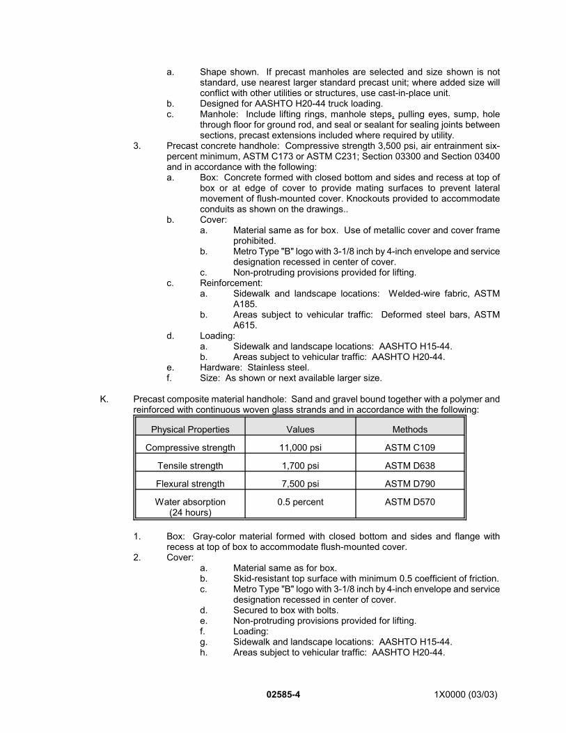
02585-4 1X0000 (03/03)
a. Shape shown. If precast manholes are selected and size shown is notstandard, use nearest larger standard precast unit; where added size willconflict with other utilities or structures, use cast-in-place unit.
b. Designed for AASHTO H20-44 truck loading.c. Manhole: Include lifting rings, manhole steps, pulling eyes, sump, hole
through floor for ground rod, and seal or sealant for sealing joints betweensections, precast extensions included where required by utility.
3. Precast concrete handhole: Compressive strength 3,500 psi, air entrainment six-percent minimum, ASTM C173 or ASTM C231; Section 03300 and Section 03400and in accordance with the following:a. Box: Concrete formed with closed bottom and sides and recess at top of
box or at edge of cover to provide mating surfaces to prevent lateralmovement of flush-mounted cover. Knockouts provided to accommodateconduits as shown on the drawings..
b. Cover:a. Material same as for box. Use of metallic cover and cover frame
prohibited.b. Metro Type "B" logo with 3-1/8 inch by 4-inch envelope and service
designation recessed in center of cover.c. Non-protruding provisions provided for lifting.
c. Reinforcement:a. Sidewalk and landscape locations: Welded-wire fabric, ASTM
A185.b. Areas subject to vehicular traffic: Deformed steel bars, ASTM
A615.d. Loading:
a. Sidewalk and landscape locations: AASHTO H15-44.b. Areas subject to vehicular traffic: AASHTO H20-44.
e. Hardware: Stainless steel.f. Size: As shown or next available larger size.
K. Precast composite material handhole: Sand and gravel bound together with a polymer andreinforced with continuous woven glass strands and in accordance with the following:
Physical Properties Values Methods
Compressive strength 11,000 psi ASTM C109
Tensile strength 1,700 psi ASTM D638
Flexural strength 7,500 psi ASTM D790
Water absorption(24 hours)
0.5 percent ASTM D570
1. Box: Gray-color material formed with closed bottom and sides and flange withrecess at top of box to accommodate flush-mounted cover.
2. Cover:a. Material same as for box.b. Skid-resistant top surface with minimum 0.5 coefficient of friction.c. Metro Type "B" logo with 3-1/8 inch by 4-inch envelope and service
designation recessed in center of cover.d. Secured to box with bolts.e. Non-protruding provisions provided for lifting.f. Loading:g. Sidewalk and landscape locations: AASHTO H15-44.h. Areas subject to vehicular traffic: AASHTO H20-44.
1X0000 (03/03) 02585-5
i. Hardware: Stainless steel.j. Size: As shown or next available larger size.
L. Aggregate for Subgrade Foundation: ASTM C33, coarse aggregate No. 4 and No. 67.
M. Spacer: As shown or recommended by conduit manufacturer.
N. End Bells: Flared, smooth-surfaced fittings of same material as conduit; if of differentmaterial, include adaptor for connection to conduit.
O. Grounding: Section 16060.
P. Brick: Section 04215.
Q. Mortar: Section 04050.
PART 3 - EXECUTION
3.01 EXCAVATING AND BACKFILLING:
A. Excavating and backfilling: In accordance with Section 02320.
B. If ducts and manholes are to be installed on backfill over subway structure, place andcompact backfill up to grade shown for ductbanks, conduits, manholes and handholes;compact as specified in Section 02320; ensure the manhole sets level. Schedule completionof backfilling to allow sufficient time for installation of ductbanks, conduits, manholes andhandholes.
C. Where shown for subgrade foundation, use layers of coarse aggregate No. 4 and No. 67 incombinations and proportions determined by field conditions.
3.02 PAVEMENTS, SIDEWALKS, CURBS AND GUTTERS:
A. Remove pavements, sidewalks, curbs and gutters where necessitated by construction ofductbanks, manholes and handholes in accordance with Section 02220.
B. Place temporary bituminous pavement in accordance with Section 02740, when necessarybecause of sequence of operations.
C. On completion of construction, replace pavements, sidewalks, curbs and gutters inaccordance with Section 02205.
3.03 INSTALLATION:
A. General:1. Use size, type, general routing and locations of ductbanks, conduits, manholes and
handholes as shown and specified.
B. Ductbanks:1. Place conduits in ductbanks on spacers or construct concrete base prior to placing
bottom row of conduits.2. Use spacers to provide conduit spacing and support as recommended by conduit
manufacturer.3. Make conduit joints watertight by complying with recommendations of conduit
manufacturers and as follows:
02585-6 1X0000 (03/03)
a. PVC conduit: Use solvent cement to join conduits, elbows and fittings.b. Galvanized steel rigid conduit: Use lead-free conductive anti-seize
compound on threaded conduit joints.c. Fiberglass conduit: Use adhesive to join conduits, elbows and fittings for
water tightness and pull out strength. Follow instructions of conduitmanufacturer for using adhesive during periods below the recommendedtemperature range. Use of rubber sealing gaskets and interference typejoints is prohibited.
4. Use Schedule 40 PVC conduit for underground ductbanks except as follows:a. Use galvanized steel rigid conduit only in specific locations as shown.b. Use fiberglass conduit only for providing utility company’s 13.8 kv electric
services.5. Place and compact concrete around conduits in accordance with Section 03300.6. Where shown, install reinforcing steel in concrete encasement in accordance with
Section 03200.7. Bends:
a. Unless otherwise shown or specified, install conduit bends in accordancewith reference codes.
b. Install bends in buried conduit in accordance with the following:
Size ofconduit
in inches
Minimum radiusof factory-bend
in inches
Minimum radiusof field-bend
in inches
3 18 24
4 24 30
5 48 48
6 48 48
c. Total bends in each conduit run for traction-power cable: 225 degreesmaximum.
d. Bend conduit so that field-made bend is free from cuts, dents and othersurface damage.
e. Field-made bends in fiberglass conduits are prohibited.8. Support conduit during construction using compatible conduit supports and spacers
to maintain positions of conduit during placement of concrete and to ensureindependent support.
9. Install conduit so that it drains to adjacent manhole or handhole.10. Prevent concrete and other foreign materials from entering, obstructing or deflecting
conduit. Cap or plug conduit ends prior to pouring concrete.11. Remove burrs from conduit ends, clean and dry before applying solvent cement to
PVC conduit joints or adhesive to fiberglass conduit joints.12. Pull approved test mandrel and swab through each conduit after installation. Cap
or plug conduit ends. If mandrel cannot be pulled through conduit, replace conduit.13. Leave approved nylon or polyester pull-line in each conduit.14. At the ends of each conduit, use corrosion-resistant metallic tags with stamped
markings to establish identification in accordance with designations shown. Installtags securely to permanent structure near each conduit as approved by theEngineer.
15. Install caps at empty conduit ends for future use.
C. Conduits Without Concrete Encasement:1. Use Schedule 80 for direct-buried train control conduit.
1X0000 (03/03) 02585-7
2. Install caps on ends of empty train control conduits and identify locations of conduitends with stakes.
3.04 CONSTRUCTION OF MANHOLES AND HANDHOLES:
A. Provide drainage facilities for manholes and handholes where shown. If connection is madeto existing sewer line, install connection in accordance with applicable local regulations
B. Erect formwork in accordance with Section 03100.
C. Place reinforcing in accordance with approved shop drawings.
D. Provide for location of ductbank entrances and inserts in walls as shown.
E. Place concrete as specified in Section 03300.
F. Install conduits of material shown.
G. Install end bells on conduits where ductbanks terminate in manholes and handholes.
H. Build ductbank formation into walls of manholes and handholes and seal around opening.
I. If location of manholes and handholes openings will be obstructed, so inform the Engineer.
J. Install frame and cover, adjusting to finished grade, building brick chimney as specified inSection 02535.
K. Seal conduit openings with approved conduit plugs.
L. Install cable pulling eyes and steps as shown. Test pulling eye for compliance with specifiedpullout load rating.
M. Install ground rods, 2-inch by 1/4-inch by 12-inch long ground bus bar and insulatedgrounding conductors where shown. If soil conditions prevent driving rod to required depth,install alternative grounding system as approved. Provide grounding for personnel protectionas specified in Section 16060.
N. When installing sections of precast manholes and handholes, prevent damage to joints seals.
O. Provide full-height stainless steel channel inserts approximately two feet on center alonginterior walls, spaced to clear ductbank entrances and steps. Use expansion bolt anchorsto secure channel inserts to walls. Install and test channel inserts in accordance with Section16130.
3.05 INSTALLATION OF HANDHOLES:
A. Bury precast concrete or composite material handholes with cover mounted flush with finishgrade or pavement. Comply with installation procedures furnished by manufacturer.
3.06 CLEAN UP:
A. Remove debris from manholes and handholes and ensure complete installation is left in neatand finished condition.
02585-8 1X0000 (08/01)
3.07 FIELD QUALITY CONTROL:
A. Arrange with the Engineer for inspection and approval of conduits in ductbank and cast-in-place manholes and handholes prior to concrete placement.
B. Arrange with the Engineer for a representative of the utility company to inspect and approveservice conduits for Authority facilities, relocated utility conduits, manholes and handholesprior to concrete placement.
C. Arrange with the Engineer for inspection and approval of direct-buried conduits for future traincontrol circuits, prior to backfilling.
END OF SECTION
1X0000 (03/03) 02625 - 1
SECTION 02625
SUBWAY DRAINAGE SYSTEM
PART 1 - GENERAL
1.01 DESCRIPTION:
A. This section specifies providing subway drainage system except drainage pumping system.
B. Related Work Specified Elsewhere:1. Grading, excavating and backfilling: Section 02320.2. Concrete work: Sections 03100, 03200 and 03300.3. Drainage pumping station: Section 15444.4. Piping systems: Section 15205.
1.02 SUBMITTALS:
A. Submit the following for approval in accordance with the General Requirements and with theadditional requirements as specified for each:1. Samples:
a. Submit proposed materials not less than ten days prior to date of expectedfirst shipment.
2. Shop Drawings:a. Include complete catalog information and shop drawings for material and
equipment.3. Certification.
1.03 QUALITY ASSURANCE:
A. Codes, Regulations, Reference Standards and Specifications:1. Comply with codes and regulations of the jurisdictional authorities.2. AASHTO: M352.3. ASTM: A48, B271, B584, C33, C131, C654, C700, D1785, D2729.
PART 2 - PRODUCTS
2.01 PRODUCTS AND MATERIALS:
A. Porous Concrete Pipe:1. Extra strength: ASTM C654.2. Tongue-and-groove joints formed of solid concrete.
B. Vitrified Clay Pipe: ASTM C700, standard strength, extra strength, as shown.
C. Plastic Pipe and Fittings:1. PVC pipe: ASTM D2729 or ASTM D1785.2. Polyethylene corrugated pipe: AASHTO M352. Individual lengths not less than10feet.
Coil pipe not permitted for pipe eight inches in diameter or larger.3. Fittings:
a. Polyvinyl chloride: ASTM D2729 or ASTM D1785.b. Polyethylene, corrugated: AASHTO M352.
D. Manholes:
02625 - 2 1X0000 (03/03)
1. Formwork: Section 03100.2. Concrete reinforcement: Section 03200.3. Concrete: Section 03300, Class 3500.Manhole frames and covers, inlet frames and
grates: a. Authority manhole: Cast-iron, ASTM A48, Class 30, with METRO logo. Size
as shown.b. Rust-resistant cast iron or rust-resistant malleable cast iron, fabricated as
shown.c. True to pattern in form and dimensions, free from pouring faults,
sponginess, cracks, blowholes and defects affecting strength.d. Fillets at angles in casting with arises sharp and perfect.e. Sandblasted to effectively remove scale and sand, presenting smooth, clean
and uniform surfaces. Coated with bituminous coating.f. Covers to receive paver tile.
1) Omit bituminous coating.2) Provide positioning lug and receptor permanently part of cover and
frame rim so that cover can only be installed (flush) in one position.
E. Drainage Castings:1. Drain inlets, cleanouts, floor and scupper drains fabricated from cast iron: ASTM
A48, Class 25 with brass parts, Alloy Number 844.2. Copper alloy sand castings: ASTM B584.3. Copper base alloy centrifugal castings: ASTM B271.
F. Drainage Casting Covers:1. Cast iron: ASTM A48, Class 30.2. Copper alloy: ASTM 584.
G. Wire Mesh Screen:1. Bronze or stainless steel wire, minimum .047-inch diameter, 1/4-inch mesh.
H. Porous Subgrade Material:1. Coarse aggregate: ASTM C33, Size No. 67.2. Maximum percentage of wear: 45 percent when tested in accordance with ASTM
C131.I. Drainage Pumping Station: Section 15444.
PART 3 - EXECUTION
3.01 EXCAVATION:
A. Excavate to lines and grades shown in accordance with Section 02320.
3.02 POROUS MATERIAL PLACEMENT:A. Place porous material for subgrade around main track drain and drain pipes and for trench
backfill as shown.
B. In rock excavation, do not place porous subgrade material on excavated rock surface untilsurface has been flushed with water to remove fine dust and sludge.
C. Place material only on stable rock surfaces.
3.03 VITRIFIED CLAY PIPE:
1X0000 (03/03) 02625 - 3
A. Place vitrified clay pipe to lines and grades shown.
B. Make joints in accordance with manufacturer's instructions.
C. Place concrete encasement where shown in accordance with Section 03300. Secure pipeto avoid displacement during concrete placement.
3.04 POROUS CONCRETE PIPE:
A. Lay pipe on porous subgrade material so as to provide full bearing and grades shown.
B. Install joints in accordance with the manufacturer's instructions.
C. Place porous material over and around the pipe as shown.
D. Place perforated pipe as specified with the perforations downward.
E. Place concrete for encasement in accordance with Section 03300.
F. Place and brace pipe for encasing to prevent displacement during placing of concrete.
3.05 PLASTIC PIPE:
A. Lay plastic pipe as specified for porous concrete pipe.
B. Use nonpressure pipe for drainage.
C. Use cast iron, concrete or vitrified clay pipe for last two feet at exposed termination points.Provide standard adaptor fittings for connections between differing pipe materials.
D. Plastic pipe may be used only if buried or encased in concrete. Its use is prohibited inexposed locations.
3.06 MANHOLES:
A. Construct cast-in-place concrete manholes as shown.
B. Construct flow channel in manhole where shown.
C. Place axis of manholes directly over centerlines of pipes unless otherwise shown.
D. Set manhole frame and cover or grate to required elevation. Set ballast screen whereshown.
3.07 INSTALLATION OF PIPE AND CASTINGS:
A. Install cast-iron, ductile-iron, nickel-copper alloy steel pipe and fittings meeting therequirements of Section 15205.
B. Install drainage piping to the lines and grades shown.
C. Locate drainage castings and set to the finished floor elevation, slabs or inverts.
D. Install cleanouts at the locations shown.
02625 - 4 1X0000 (03/03)
3.08 PROTECTION OF DRAINAGE SYSTEM:
A. During the course of construction, maintain drainage lines free of debris and in undamagedcondition.
B. Plug or close ends of completed runs of piping until the Engineer approves their use.
C. Cover the inlet end of drainage piping used to convey water to wet wells at the existingdrainage pumping stations with wire mesh screen.
3.09 FIELD QUALITY CONTROL:
A. Where drainage piping is located below invert slabs, conduct a ball, shuttlecock, or mandreltest to ensure that the line is free of obstructions subsequent to the placing of poroussubgrade material over the line and prior to the placement of the concrete invert slab.
B. Upon completion of the test and determination that the line is free of obstructions, plug, capor otherwise close the open end or ends of the installed piping to prevent the entrance ofdebris into the lines.
C. Immediately prior to final inspection of the work, remove debris from manholes, drain inlets,and floor scupper drains. In the presence of the Engineer, prove by one of the methodsspecified above that the piping is free of obstructions.
END OF SECTION
1X0000 (03/03) 02635 - 1
SECTION 02635
STORM SEWER
PART 1 - GENERAL
1.01 DESCRIPTION:
A. This section specifies installing storm sewers, roadway drains, roadway underdrains, ditchlining and slope protection.
B. Related Work Specified Elsewhere:1. Grading, excavating and backfilling: Section 02320.2. Maintenance, support and restoration of utility facilities: Section 02270.3. Stray current and cathodic protection: Section 13110 and 13115.
C. Material Furnished By Others: *11. Except for those items which bear the METRO logo, WSSC furnishes the following:
a. Manhole frames and covers: 22-inch diameter.b. Manhole steps, except where precast manholes are used.
D. Definitions: *21. Granular bedding required by WSSC is equivalent to aggregate for pipe cradle as
specified.2. WSSC: Washington Suburban Sanitary Commission.3. WASA: Water and Sewer Authority.
1.02 SUBMITTALS:
A. Submit the following for approval in accordance with the General Requirements and with theadditional requirements as specified for each:1. Shop Drawings:
a. Drawings for each size and configuration of precast manhole with details ofaccessories and joints.
b. Diagrams showing dimensioned locations for openings in precast concretemanhole walls.
2. Documentation:a. Submit calculations for modified or special designs to demonstrate
compliance with required load-bearing capacity, certified by a professionalengineer registered in the jurisdiction where the work is to be installed.
3. Samples:a. Sewer brick: Ten.b. Manhole brick: Ten.c. Slope protection materials:
1) Concrete blocks: Ten each.2) Paving bricks: Ten each.3) Riprap: 1.5 cubic yards.4) Gabions: Two each, complete.
d. Geotextile filter fabric: Two, 12 inches long by 12 inches wide, minimum.
4. Certification.5. Documentation: *3
a. Submit two copies of records of inspection of new and relocated sewers,one copy to W\SSC and one copy to the Engineer. Include video-tape
02635 - 2 1X0000 (03/03)
cassette of television inspections and logs, photographs and other recordsspecified by WASA for visual walk-through inspections.
b. Obtain and submit a written approval and acceptance from WASA.
1.03 QUALITY ASSURANCE:
A. Codes, Regulations, Reference Standards and Specifications:1. Comply with codes and regulations of the jurisdictional authorities.2. Building Stone Institute: Stone Catalog.3. CISPI: HSN 85.4. AASHTO: M33, M36, M153, M175, M176, M190, M252, M288, T85, T96, T104. *45. AASHTO: H20, M33, M36, M153, M175, M176, M190, M252, M288, T85, T96,
T104. *56. ANSI/ASME: B16.1. *67. ACI: 318. *78. ASTM: A36, A48, A53, A74, A167, C14, C32, C33, C76, C144, C150, C207, C361,
C425, C443, C478, C507, C700, D698, D1682, D3034, D5034, D5035. *89. ASTM: A36, A48, A53, A74, A167, C14, C32, C33, C76, C144, C150, C207, C361,
C425, C443, C478, C700, D698, D1682, D3034, D5034. D5035. *910. MS: MIL-P-23236.11. SSPC: SP-6.12. WSSC: General Conditions and Standard Specifications. *10
B. Source Quality Control:1. Ditch lining and slope protection materials:
a. After approval, do not change source.b. Replace defective material.
C. Allowable Tolerances:1. Subgrade: Plus-or-minus 1/2 inch of elevation shown.
D. Inspection: *11
1. Prior to paving or other construction over new or relocated sewers, conduct visualwalk-through inspection of sewers larger than 36 inches in diameter and ofassociated structures and internal television inspection of sewers 36 inches andsmaller in diameter.
2. Employ the services of a sewer inspection company which has been regularlyengaged in television sewer inspections and which is acceptable to WASA toperform preconstruction and post-construction inspections of sewers 36 inches andsmaller in diameter.a. Submit to WASA for prior approval one sample of the cassettes to be used.
PART 2 - PRODUCTS
2.01 MATERIALS:
A. Formwork: Section 03100.
B. Reinforcing Steel: Section 03200.
C. Portland Cement Concrete: Section 03300, Class 3500, unless otherwise shown.
D. Aggregate for Subgrade Foundation: ASTM C33, coarse aggregate, No. 4. Where shownuse layers of No. 4 and No. 67 in combinations and proportions determined by fieldconditions and as approved.
1X0000 (03/03) 02635 - 3
E. Aggregate for Pipe Cradle: ASTM C33, coarse aggregate No. 67.
F. Concrete Pipe:1. 10-inch diameter and smaller:
a. ASTM C14, Class 2, nonreinforced concrete pipe.b. Bell-and-spigot type.c. Joints fabricated in accordance with ASTM C361. Physical characteristics
for rubber gaskets in accordance with ASTM C443.2. 12-inch diameter and larger:
a. ASTM C76, bell-and-spigot or tongue-and-groove, Class IV, unlessotherwise shown.
b. Radius (bevel) pipe, with drop between two pipe sections not exceeding thecommon wall thickness.
c. Rubber gasket joints, when required, fabricated in accordance with ASTMC361. Physical characteristics for rubber gaskets in accordance with ASTMC443.
d. Acceptance tests as specified in ASTM C76 form basis of acceptance forconcrete pipe in accordance with the following:1) 72-inch diameter and smaller: Acceptance on the Basis of Plant
Load Bearing Test, Material Tests and Inspection of ManufacturedPipe for Visual Defects and Imperfections.
2) Larger than 72 inches in diameter: Acceptance on the Basis ofMaterial Tests and Inspection of Manufactured Pipe for Defects andImperfections.
e. Minimum laying lengths: Four feet.f. Rubber gaskets: ASTM C361. *12
g. Rubber gaskets: ASTM C443. *13
h. Jointing mastic: Elastic, water-resistant, formulation of plastic bituminousmaterials, nonflammable solvent and inert fillers so combined that:1) When applied to a vertical metal surface and heated to 120F,
jointing mastic will neither slump nor lose plasticity.2) When applied directly from container without further fixing, jointing
mastic can be applied in even, adherent coat within temperaturerange of 20F to 100F.
i. Reinforced concrete elliptical pipe: ASTM C507. *14
3. Perforated nonreinforced concrete pipe: AASHTO M175, Type 1 or 2, bell-and-spigot or tongue-and-groove type.
4. Porous concrete pipe: AASHTO M176, tongue-and-groove.
G. Plastic Pipe:1. Polyvinyl chloride (PVC) pipe: ASTM D3034, SDR-35.2. Polyethylene corrugated pipe: AASHTO M252.
H. Bituminous-Coated Corrugated Metal Pipe: AASHTO M190, Type A or C, with connectingbands, AASHTO M36.
I. Vitrified Clay Pipe: ASTM C700; Joints, ASTM C425, using plastic materials.
J. Cast-Iron Soil Pipe and Fittings: ASTM A74, extra-heavy (XH), with hub and spigot ends soconstructed that joints may be made with gaskets conforming to CISPI Designation HSN 85and the requirements of the relevant plumbing codes.
K. Lubricant for Rubber Gasket Pipe Joints: Vegetable oil soap.
L. Mortar Materials:
02635 - 4 1X0000 (03/03)
1. Portland cement: ASTM C150, Type I.2. Sand: ASTM C144, natural sand.3. Lime: Pressure-hydrated, ASTM C207, Type S.4. Water: Potable.5. Pigment: As approved.
M. Brick: ASTM C32; solid brick; Grade MS for manhole brick, Grade SS for sewer brick; 2-1/4inches by 3-3/4 inches by eight inches.
N. Precast Concrete Manhole Sections: *15
1. ASTM C478.2. Joint entry seal gasket: A-LOK as manufactured by Atlantic Precast Concrete, Inc.;
A-LOCK gaskets, manufactured by A-LOK Products Corporation, Trenton, N.J.;DURAC-SEAL gaskets, manufactured by DURA-CRETE, Inc., Dayton, Ohio; orequal.
O. Precast Concrete Manholes: *16
1. Cylindrical, eccentrical and conical: ASTM C478.2. Other configurations: ACI 318, AASHTO H20.
P. Manhole Steps:1. Cast iron: ASTM A48 Class 30 A.2. Rebar: No. 4 reinforcing bar with molded polypropelene or rubber encasement.
Q. Manhole Frame and Cover; Inlet Frame and Grate; and Ballast Screen;1. Authority manhole: Cast-iron, ASTM A48, Class 30, with METRO logo. 2. Rust-resistant cast iron or rust-resistant malleable cast iron.3. True to pattern in form and dimensions, free from pouring faults, sponginess, cracks,
blowholes and defects affecting strength.4. Fillets at angles in casting with arises sharp and perfect.5. Sandblasted to effectively remove scale and sand, presenting smooth, clean and
uniform surfaces. Coated with bituminous coating.6. Covers that receive paver tile:
a. Omit bituminous coating.b. Provide positioning lug and lug receptor as a permanent part of the cover
and frame rim so that the cover can only be installed (flush) in one position.
R. Metal Water Seals for Basin Connections: Neenah Foundry Model No. R-3707 or equal.
S. Structural Steel Members: ASTM A36.
T. Steel Pipe: ASTM A53, black finish, extra strong wall class.
U. Stainless Steel Angle: ASTM A167, Type 304.
V. Jute for Caulking: Good quality jute, free from tar, oil, or grease and dry when installed.
W. Preformed Expansion Joint Fillers: AASHTO M153, Type I, Type II or Type III.
X. Bituminous Expansion Joint Filler: AASHTO M33.
Y. Galvanizing: Section 05120.
Z. Ditch Lining and Slope Protection:1. Riprap: Material meeting the following requirements:
1X0000 (03/03) 02635 - 5
a. Hard, durable and free of fractures; angular in shape; weather-resistant; andfree from overburden, spoil, shale and organic material.
b. Size: Weight distribution of pieces provided in accordance with thefollowing:1) Class I: From 50 to 150 pounds with 60-percent minimum weighing
100 pounds or more; approximately 10 percent may weigh 50pounds or less.
2) Class II: From 150 to 500 pounds with 50-percent minimumweighing more than 300 pounds; approximately 10 percent mayweigh 150 pounds or less.
c. Quality:1) Water absorption: 3.0-percent maximum when tested in
accordance with AASHTO T85.2) Specific gravity: 2.5 minimum when tested in accordance with
AASHTO T85.3) Resistance to abrasion: Grade B maximum when tested in
accordance with AASHTO T96.4) Soundness: Loss 20-percent maximum when tested in accordance
with AASHTO T104.2. Aggregate filter:
a. Coarse aggregate, ASTM C33, Size 357.b. Use only tough, durable materials free of thin, flat, elongated or soft friable
particles and free of organic matter.3. Granite block facing: Type 4, quarry split finish on face and edges.4. Sand cushion for concrete block: Section 03300, fine aggregate.
AA. Geotextile Filter Fabric: AASHTO M288 and the following additional requirements:1. Woven or non-woven pervious filter fabric weighing approximately 0.03 to 0.05
pounds per square foot; free of defects.2. Fabric: Long chain synthetic polymer composed of at least 85 percent by weight of
propylene, ethylene, ester, amide or vinyl-chloride and with stabilizers or inhibitorsto make fabric resistant to deterioration due to ultraviolet and heat exposure.
3. Fabric formed or treated so that filaments retain their positions relative to each other.4. Edges selvaged.5. Physical strength:
a. Tensile strength: 200-pound minimum in each direction, ASTM D1682.b. Elongation at failure: 10 to 30 percent, ASTM D5034 amd D5035.c. Puncture strength: 70-pound minimum, ASTM D5034 and D5035.
6. Percent of open area: Not less than five percent nor more than six percent.7. Equivalent opening size (E.O.S.): 70-100 US Standard Sieve, CW-02215-77.8. Securing Pins: As recommended by manufacturer of filter fabric.
BB. Gabions:1. Wire mesh: Galvanized steel wire 0.105 minimum diameter, 60,000 pounds per
square inch tensile strength, galvanized at rate of 0.80 ounces per square foot.Wires twisted to form nonraveling hexagonal openings of uniform size, not to exceed4-1/2 inches in length nor eight square inches in area of mesh opening. Horizontaldimension uniform, not to exceed 36 inches. Gabion dimensions not to vary morethan three percent from manufacturer's stated size.
2. Tie devices: Malleable iron or steel, producing frictional force of 160 pounds per footof spacing. Sized to conform to requirements of jurisdictional agency.
3. Stone: Durable, free from cracks and seams, unweathered, weighing between fourpounds (four-inch average diameter) and 30 pounds (eight-inch average diameter)except five percent may vary more or less and 50 percent to exceed 10 pounds.a. Stone size:
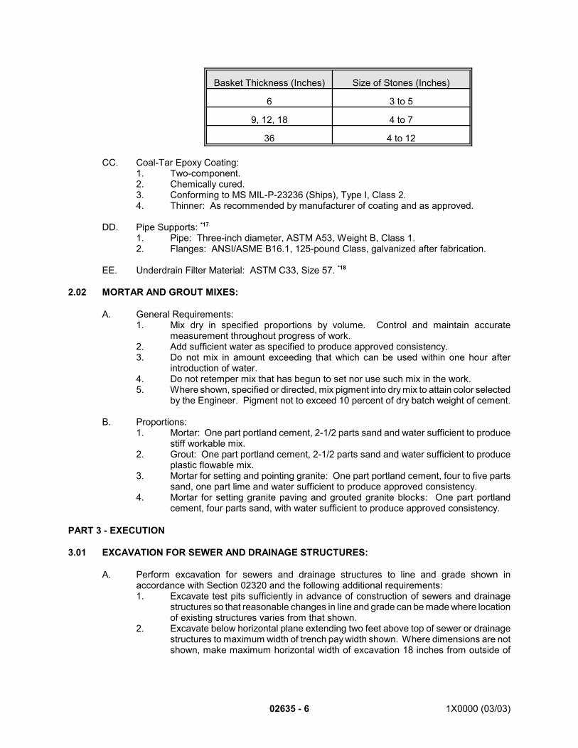
02635 - 6 1X0000 (03/03)
Basket Thickness (Inches) Size of Stones (Inches)
6 3 to 5
9, 12, 18 4 to 7
36 4 to 12
CC. Coal-Tar Epoxy Coating:1. Two-component.2. Chemically cured. 3. Conforming to MS MIL-P-23236 (Ships), Type I, Class 2.4. Thinner: As recommended by manufacturer of coating and as approved.
DD. Pipe Supports: *17
1. Pipe: Three-inch diameter, ASTM A53, Weight B, Class 1.2. Flanges: ANSI/ASME B16.1, 125-pound Class, galvanized after fabrication.
EE. Underdrain Filter Material: ASTM C33, Size 57. *18
2.02 MORTAR AND GROUT MIXES:
A. General Requirements:1. Mix dry in specified proportions by volume. Control and maintain accurate
measurement throughout progress of work.2. Add sufficient water as specified to produce approved consistency.3. Do not mix in amount exceeding that which can be used within one hour after
introduction of water.4. Do not retemper mix that has begun to set nor use such mix in the work.5. Where shown, specified or directed, mix pigment into dry mix to attain color selected
by the Engineer. Pigment not to exceed 10 percent of dry batch weight of cement.
B. Proportions:1. Mortar: One part portland cement, 2-1/2 parts sand and water sufficient to produce
stiff workable mix.2. Grout: One part portland cement, 2-1/2 parts sand and water sufficient to produce
plastic flowable mix.3. Mortar for setting and pointing granite: One part portland cement, four to five parts
sand, one part lime and water sufficient to produce approved consistency.4. Mortar for setting granite paving and grouted granite blocks: One part portland
cement, four parts sand, with water sufficient to produce approved consistency.
PART 3 - EXECUTION
3.01 EXCAVATION FOR SEWER AND DRAINAGE STRUCTURES:
A. Perform excavation for sewers and drainage structures to line and grade shown inaccordance with Section 02320 and the following additional requirements:1. Excavate test pits sufficiently in advance of construction of sewers and drainage
structures so that reasonable changes in line and grade can be made where locationof existing structures varies from that shown.
2. Excavate below horizontal plane extending two feet above top of sewer or drainagestructures to maximum width of trench pay width shown. Where dimensions are notshown, make maximum horizontal width of excavation 18 inches from outside of
1X0000 (03/03) 02635 - 7
sewer or drainage structure and minimum six inches. Where approved, excavationabove such plane may exceed specified dimensions.
3. If excavation exceeds permissible dimensions, encase pipe or install pipe of higherstrength.
4. Where necessary to place backfill or embankment so that trench can be excavated,extend backfill or embankment full depth laterally at least 2-1/2 times diameter ofpipe on each side measured from centerline of pipe.
3.02 GEOTEXTILE FILTER FABRIC:
A. Prepare surface to receive fabric to relatively smooth condition free of obstructions,depressions, debris and soft or low density pockets of material.1. Place fabric with long dimension parallel to centerline of trench and lay smooth and
free of tension, stress, folds, wrinkles or creases with sufficient excess to allow forminimum overlap of 12 inches.
2. Place strips in trench to provide minimum width of 12 inches of overlap for each joint.3. Insert securing pins with washers through both strips of overlapped fabric at not
greater than 3-foot intervals along a line through the midpoint of overlap at joints.4. Where this method of placement conflicts with manufacturer's instructions, the
manufacturer's instructions prevail.
B. At time of installation fabric to be rejected if it has defects, rips, holes, flaws, deterioration ordamage incurred during manufacture, transportation, storage or handling.
C. Place fabric in manner and at location shown.
3.03 PIPE CRADLE:
A. Place pipes on cradle of aggregate or concrete where shown.
B. Place aggregate so as to avoid segregation; compact to maximum practicable density so thatpipe can be laid to required tolerances.
3.04 LAYING PIPE:
A. General Requirements:1. Excavate to lines and grades shown in accordance with Sections 02320 and herein.
Excavate depressions for bells.2. Protect pipe and fittings during handling to prevent damage.3. Place, shape and compact bedding material to receive barrel of pipe. Type and
thickness of bedding material as shown.4. Start laying pipe at lowest point; lay true to line and grade shown.5. Install pipe to bear on bedding material along entire length. Shape bedding material
to fit bells and flanges.6. Install perforated pipe with perforations downward.7. Install pipe so that bells and grooves are on upstream end.8. Align each section of pipe with adjoining section with uniform annular space between
bell and spigot and so as to prevent sudden offsets in flow line.9. As each section of pipe is laid, place sufficient backfill to hold it firmly in place.10. Keep interior of sewer clean as work progresses. Where small pipe size makes
cleaning difficult, keep suitable swab or drag in pipe and pull through each jointimmediately after jointing is completed.
11. Keep trenches and excavations free of water during construction and until backfilled.Each day, excavate only as much trench as needed to lay pipe.
02635 - 8 1X0000 (03/03)
12. When work is not in progress, securely plug ends of pipe and fittings to preventtrench water or other substances from entering pipes and fittings.
13. Where length of stub is not shown, install four-foot length and seal free end withbrick masonry bulkhead or approved stopper.
14. Have work approved prior to covering pipe.15. Where shown, place additional aggregate filter around and over pipe in lifts not
exceeding six inches loose. Compact each lift before placement of next lift.16. Backfill in accordance with Section 02320.17. Accomplish compaction by method that will avoid damage to pipe and will not disturb
its alignment and grade. The use of vibratory rollers is prohibited until compactedcover over pipe has reached three feet or half the pipe diameter, whichever isgreater.
18. Where cathodic protection is shown, apply coal-tar epoxy coating.
B. Vitrified Clay Pipe:1. Nonperforated pipe:
a. Use pipe hoist, crane or other approved device when laying pipe greaterthan 18 inches diameter.
b. Prevent damage to premolded joint rings or attached couplings.c. Clean joint contact surfaces immediately prior to jointing. To complete joint,
use lubricants, primers or adhesives as recommended by pipe or jointmanufacturer
2. Perforated pipe:a. Firmly position spigot in bell of preceding pipe. Saturate jute gasket in
cement grout and caulk into annular space. Ensure that jute is long enoughto reach entirely around pipe and is of such thickness to bring pipe sectionsto same grade.
b. After pipe sections have been caulked and centered, fill annual space withcement mortar.
c. After mortar joints have set, place additional aggregate filter material asspecified.
C. Concrete Pipe:1. Bell-and-spigot joints:
a. Lay bell-and-spigot joint pipe as specified for vitrified clay pipe.2. Tongue-and-groove joints:
a. Clean groove end of preceding pipe with wet brush and apply soft mortar tolower 1/4 of groove. Clean tongue end of succeeding pipe with wet brushand position it. Remove mortar from interior surface if squeezed out of joint.
b. Complete mortaring interior and exterior portions of joint for entirecircumference, extending from previously placed mortar. Perform finalexterior mortaring of joints three lengths of pipe behind laying.
D. Plastic Pipe:1. Perforated pipe:
a. Use sleeve couplings designed to hold pipe in alignment without use ofsealing compound or gaskets.
b. Place additional aggregate filter material as specified.c. Cap open ends of underdrains.
2. Nonperforated pipe:a. Join sections of pipe with couplings recommended by pipe manufacturer.
E. Corrugated Metal Pipe:1. Perforated pipe:
a. Place additional aggregate filter material as specified2. Nonperforated pipe:
1X0000 (03/03) 02635 - 9
a. When pipe is shown to be bituminous paved, place paved area on bottom.3. Connections for corrugated metal pipe:
a. Join sections of pipe with coupling bands arranged to fit corrugationsaccurately.
b. Do not damage protective coating when tightening bolts.c. After final tightening of connection bolts, apply brush coat of bituminous
paint to bands and bolts.
F. Porous Concrete Pipe:1. Fill joints with mortar as specified for tongue-and-groove joints of concrete pipe.2. After pipe joints have been made, place additional filter material as specified.
G. Inspections Of Sewers: *19
1. Perform all work in accordance with current requirements of WASA.2. Perform inspections on new or relocated storm sewers within or adjacent to the zone
of influence, as defined by the limits of a theoretical slope of 1:1 from the bottomedges of tunneling and cut-and-cover excavations, as follows:a. Make inspections upon completion of tunneling and cut-and-cover
operations, but prior to paving.b. Obtain video-tape television inspection records of sewers 36 inches and
smaller in diameter.c. By means of visual walk-through inspection, obtain coordinated logs,
photographs and other records specified by WASA of sewers larger than 36inches in diameter and of associated structures.
3. Coordinate all television and walk-through inspection field operations with WASA.All such work to be performed in the presence of a WASA representative.
3.05 BACKFILL:
A. Perform backfilling only after inspection and approval of pipe laying.
B. On completion of construction, backfill excavation in accordance with Section 02320.
3.06 JOINTS FOR CONCRETE STORM SEWER: *20
A. Use cold-applied jointing mastic for joints of storm sewer.
B. Bell-and-Spigot Joints:1. Clean interior surface of bell and fill lower portion with mastic of sufficient thickness
to make inner surfaces of abutting sections flush.2. Install spigot end of adjoining pipe into bell so that sections are closely fitted and
aligned.3. Apply sufficient jointing mastic to fill remaining void in joint.4. Remove excess mastic from interior of pipe.
C. Tongue-and-Groove Joints:1. Clean groove. Apply mastic to lower half of groove.2. Clean tongue of next pipe and apply layer of mastic to upper half.3. Fit tongue into groove until pipes are closely fitted and aligned and mastic covers
inner and outer surfaces.4. Remove excess mastic from interior of pipe.
3.06 JOINTS FOR CONCRETE STORM SEWER 12 INCHES TO 33 INCHES: *21
A. Use cold applied jointing mastic for joints of storm sewer 12 inches to 33 inches in diameter.
02635 - 10 1X0000 (03/03)
B. Bell-and-Spigot Joints:1. Clean interior surface of bell and fill lower portion with mastic of sufficient thickness
to make inner surfaces of abutting sections flush.2. Install spigot end of adjoining pipe into bell so that sections are closely fitted and
aligned.3. Apply sufficient jointing mastic to fill remaining void in joint.4. Remove excess mastic from interior of pipe.
C. Tongue-and-Groove Joints:1. Clean groove. Apply mastic to lower half of groove.2. Clean tongue of next pipe and apply layer of mastic to upper half.3. Fit tongue into groove until pipes are closely fitted and aligned and mastic covers
inner and outer surfaces.4. Remove excess mastic from interior of pipe.
3.06 JOINTS FOR CONCRETE STORM SEWER 36 INCHES AND LARGER. *22
A. Where not prohibited by jurisdictional agencies, Use mortar for joints of storm sewers 36inches diameter and larger.
B. Bell-and-Spigot Joints:1. Where pipe cradle is aggregate, place shallow bed of mortar under joint.2. Thoroughly wet bell and fill lower half with mortar.3. Thoroughly wet spigot and uniformly fit into bell so that sections are closely fitted and
aligned.4. Fill remaining annular space in bell with mortar sufficient to form bead around
outside of spigot end of pipe.5. Remove excess mortar from interior of pipe and finish exterior and interior to smooth
surfaces.
C. Tongue-and-Groove Joints:1. Thoroughly wet groove; apply mortar to lower half of groove.2. Thoroughly wet tongue of next pipe and apply a layer of mortar to top half.3. Fit tongue into groove until pipes are closely fitted and aligned and mortar covers
inner and outer surfaces of the joint.4. Clean inner surface of pipes at joint and point up outside with bead of mortar.
3.07 JOINTS FOR VITRIFIED CLAY PIPE:
A. Immediately before joining vitrified pipe, liberally coat bell with lubricant and fit spigot withgasket.
B. Join pipes using equipment designed for purpose.
3.08 JOINTS FOR CAST-IRON SOIL PIPE AND FITTINGS:
A. Immediately before joining cast-iron soil pipe and fittings, liberally coat hub with lubricant andfit spigot with pipes using equipment designed for purpose.
3.09 CONNECTIONS WITH EXISTING SEWERS:
A. Make connections with existing public sewers in accordance with requirements of thejurisdictional authority.
1X0000 (03/03) 02635 - 11
B. Do not connect existing sewer to sewer under construction unless approved.
3.10 TUNNELING AND JACKING:
A. Perform tunneling and jacking by approved methods.
B. Where open cut is specified and the Engineer permits the work to be done by tunneling orjacking, perform such work as specified and as approved.
C. Cost of material substitutions required by change of methods will be borne by the Contractor.
D. Make horizontal borings necessary to lay pipe lines true to line and grade.
E. When sewers are laid in borings, completely fill void between outside barrel of pipe andboring with cement grout pumped into place.
F. When drainage pipes are laid in borings, completely fill void between pipe and boring withsand, using water pressure to ensure that voids are filled.
G. Methods of boring and filling of voids between pipe and boring are subject to approval.
3.11 CAST-IN-PLACE CONCRETE CONSTRUCTION:
A. Conform to applicable requirements of Sections 03100, 03200 and 03300. Section designerto specify the type of cement to be used. The type of cement will vary depending upon thejurisdiction where the work is performed.1. Cement. *23
B. Construct concrete support systems where shown. Section designer to specify the type ofmortar to be used. Mortar type will vary depending upon jurisdiction in which the work isperformed.1. Mortar and cement. *24
3.12 BRICK CONSTRUCTION:
A. Perform brick construction as specified in Section 04215, with the following additionalrequirements:1. Use sewer brick wherever brick construction is exposed to flow; otherwise, use
manhole brick.2. Lay sewer brick on edge so that 2-1/4 by 8-inch side is exposed to flow.3. Lay manhole brick so that every sixth course is a header course.4. Where practicable, lay each course with a line. For curved courses or those in
nonparallel planes, use bonded-and-keyed construction.5. Do not exceed joint thickness of 3/8 inch in straight courses in parallel planes; for
courses curved or in nonparallel planes, make thickest part of joint as thin aspracticable.
6. Rack or tooth uncompleted brick construction and parge unexposed surfaces with1/2 inch of mortar.
3.13 MANHOLES:
A. Construct manholes of precast sections, cast-in-place concrete or brick as shown.
B. Provide base of precast or cast-in-place construction. Make watertight connection betweenbase and risers.
02635 - 12 1X0000 (03/03)
C. Unless otherwise shown, place axes of manholes directly over centerlines of pipes.
D. Construct appropriate flow channels in bottom of manholes.
E. Where necessary, build connections for public and residential sewers into manholes. Cutpipe flush with inside wall of structure. Do not build pipe into wall; provide mortar jointbetween pipe and structure.
F. Install manhole steps and cast iron frame and cover for each manhole; adjust frame andcover to proper grade by brick construction.
G. Install joint entry seal gaskets in openings in the walls of 48-inch precast manholes with O-ring joint. *25
3.14 CATCH BASINS AND INLETS:
A. When grading has been substantially completed as approved, construct catch basins of cast-in-place concrete using Class 3500 concrete and steel reinforcement as shown, precastsections or brick as shown.
B. Cut pipe flush with inside wall of structure. Provide mortar joint between pipe and structureor install water seal as shown.
C. Install cast iron frame and grate or cover and adjust to proper grade.
D. Install pipe supports as shown. Fill with concrete after installation. *26
3.15 DITCH LINING AND SLOPE PROTECTION:
A. Slope Preparation:1. Excavate or fill slopes to the required cross section, lines and grades.2. Compact earth slopes to not less than 95 percent of the maximum dry density for a
depth of not less than 12 inches, as specified in Section 02725.3. Where lining or protection is to be applied to rock surfaces, clean off mud, debris
and loose fragments.4. Construct toe or cut off walls where shown.5. Remove loose material and buried debris protruding from subgrade.6. Placement of aggregate filter:
a. Place filter aggregate where shown to depth shown.b. Compact each layer of aggregate filter in accordance with ASTM D698,
Method D, to 100 percent at plus-or-minus one percent of optimum moisturecontent.
B. Ungrouted Riprap:1. Place aggregate filter as specified.2. Place riprap by machine to full course thickness in one operation upward from
bottom of slope. Prevent displacement of underlying materials. Dumping of riprapis prohibited.
3. Fill spaces between larger stones to produce nearly even surface with minimum ofvoids. Manually supplement machine placement of stone to choke in voids.
4. Rearrange individual stones as necessary to ensure that finished configurationconforms to lines, grades and thickness shown.
C. Bituminous Concrete Paving:
1X0000 (03/03) 02635 - 13
1. Place bituminous concrete where shown to the lines, grades, thickness and shapesshown.
2. Give base course prime coat of medium-curing, cutback asphalt and allow to curebefore hot bituminous concrete is placed.
3. Place hot-mix bituminous concrete by hand or by machine.4. When hand methods are used, place mixture by means of hot shovels or forks and
spread with hot rakes to thickness required to obtain specified compacted thickness.Thoroughly rake loose material throughout its depth, to eliminate honeycombing.Use screed boards of width equal to required thickness of lining.
5. After spreading, compact until specified compacted thickness is obtained.6. Place mixture as continuously as practicable to eliminate joints. Where joints are
required at end of a day's work or when the placing is discontinued for such periodof time that material becomes chilled, form joints as specified.
D. Cast-in-Place Concrete:1. Use Class 3500 concrete unless otherwise shown.2. Use wood or steel forms.3. Place reinforcing steel or wire mesh as shown.4. Provide and install dowel bars where shown in accordance with Section 02750.5. Locate expansion and contraction joints where shown in accordance with Section
02750.6. Unless otherwise shown, give surface wood float finish.7. Protect and cure concrete in accordance with Section 03300.
E. Concrete Masonry Units:1. Place two-inch layer of sand cushion on previously prepared slope.2. Set units firmly by hand in sand cushion with long dimension parallel to base of slope
so as to produce even surface.3. Lay blocks with open 3/8-inch joints and with joints staggered as shown.4. Completely fill joints with mortar.5. Protect and cure newly laid blocks for seven days using wet cotton mats or wet
burlap.6. Lay blocks when the temperature is 40F or above.
F. Paving Brick:1. On the previously prepared slope, place concrete base of thickness shown.2. Give concrete smooth screed finish.3. Clean base, dampen and lay one-inch thick mortar bed.4. Lay bricks with long dimension parallel to base of slope, with open 3/8-inch joints and
with joints staggered.5. Bed bricks firmly in mortar bed so as to produce even surface free from depressions
or high spots.6. Fill joints completely with mortar.7. Protect and cure newly laid brick for a period of seven days using wet cotton mats
or wet burlap.
G. Sodding: Section 02920.
H. Concrete Pavement:1. Lay plastic pipe as shown.2. Place aggregate filter as specified.3. Place concrete base in accordance with specified requirements for cast-in-place
concrete.
I. Concrete with Granite Block Facing:1. Lay plastic pipe as shown.
02635 - 14 1X0000 (03/03)
2. Place aggregate filter as specified.3. Place concrete base in accordance with specified requirements for cast-in-place
portland cement concrete.4. Installation of granite block facing:
a. et granite blocks in bedding course, one-inch minimum depth with 3/4-inchjoint width.
b. Slope bedding to true surface parallel to finished surface of blocks; strike offbedding until true alignment is attained.
c. After final sloping, do not disturb bedding prior to laying blocks.d. Lay blocks on bedding course in successive courses with quarry split finish
up.e. Align each course, lay true and even and bring to true grade by use of wood
mallets or similar tools.f. Lay blocks in continuous sequence.g. Lay no more mortar than can be covered with blocks before end of work
day.h. Point voids in joints with preshrunk mortar. Do not point when ambient
temperature is 50F and falling.After pointing, scrub surfaces with soapsolution and remove stains. Rinse immediately with clean water. Leavework in first class condition, free from mortar stain and other defacement asapproved.
J. Gabions:1. Prepare ground surface smooth and even where gabions will be installed.2. Assemble gabions and tie together in accordance with manufacturer's instructions.3. Fill gabions in lifts of 12 inches maximum. Install tie devices in all units with exposed
faces, spaced in accordance with requirements of jurisdictional agency.4. Ensure stone fill is placed without voids larger than approximately smaller stones.
Hand-place stones in exposed faces.
3.16 CONCRETE HEADWALLS AND WINGWALLS:
A. Excavation:1. Excavate for foundations and walls to lines and grades shown in accordance with
Section 02320.
B. Formwork and Reinforcement:1. Erect formwork and install reinforcement as shown and in accordance with Sections
03100 and 03200.
C. Concrete Work:1. Place concrete of class shown and protect and cure in accordance with Section
03300.
D. Backfilling:1. Backfill and compact in accordance with Section 02320.
3.17 COATING APPLICATION AND REPAIR:
A. Preparation of surface: Perform the following in order given:1. Clean surfaces contaminated with oil or grease using naphtha or xylol.2. Remove rust and mill scale from surfaces by dry abrasive blasting to commercial
finish in accordance with SSPC SP-6.3. Coat surfaces within 24 hours and before dew point is reached.
1X0000 (03/03) 02635 - 15
*1. Add 1.1 C. including 1.a.-b. for contracts where storm systems work is performed within thejurisdiction of WSSC.
4. Apply coating only to surfaces which are dry and free of contaminants. Whip blastsurfaces not coated within specified time limit.
5. Application of coating:a. Mix coating in quantity which can be applied within its pot life if in
accordance with manufacturer's recommendation. Thin only with approval.b. Apply coating to exterior surfaces of pipes and fittings in accordance with
recommendations of coating manufacturer and as follows:1) Two coats of equal thickness.2) Total dry film thickness: 20 mils.3) Pretreat first coat as required prior to application of second coat.4) Apply second coat before first coat has dried tack-free but not later
than 24 hours after application of first coat, unless otherwiserecommended by coating manufacturer.
5) Inspect coating prior to burial. Repair damages in accordance withrecommendations for field corrections by coating manufacturer.
6. Test cathodic protection as specified in Section 13115.
3.18 SUBWAY DRAINAGE SYSTEM: Section 02625.
3.19 FIELD QUALITY CONTROL:
A. Maximum Surface Variation Tolerances:1. Grouted riprap: 1-1/4 inches in four feet from true plane.2. Bituminous concrete: Plus-or-minus 1/4 inch from specified grade in 25 feet.3. Cast-in-place concrete: Plus-or-minus 1/4 inch from specified grade in 15 feet.4. Precast concrete block: Plus-or-minus 1/2 inch from specified grade in 25 feet.5. Paving brick: Plus-or-minus 1/2 inch from specified grade in 25 feet.
B. Obstruction Tests:1. Perform field tests to verify that installed storm systems are free from obstructions.2. Remove obstructions by excavating at the apparent obstruction and repairing or
replacing the defective pipe as directed by the Engineer.
3.20 TRANSPORTATION AND INSTALLATION OF MATERIALS FURNISHED BY OTHERS: *27
A. Transport and install materials furnished at the WSSC's storeyard at Bladensburg or otherdelivery points designated by the WSSC.
B. Use only suitable equipment, tools, and appliances for the safe and convenient handling andhauling of materials.
C. Check that all materials furnished by the WSSC are in satisfactory condition.
D. Materials damaged, lost or wasted after acceptance will be replaced by the WSSC at theexpense of the Contractor.
E. Material showing inherent defects will be replaced by the WSSC without charge.
SEE ENDNOTES BELOW. THEY ARE AN ESSENTIAL PART OF THIS SECTION UNTIL EDITED BYSECTION DESIGNER.
02635 - 16 1X0000 (03/03)
*2. Add 1.1 D. including 1. for contracts where storm systems work is performed within the jurisdictionof WSSC.
*3. Add 1.2 E. including 1.-2. for contracts where storm systems work is performed within the jurisdictionof WASA.
*4. Use first version of 1.3 A.4. modification for contracts where storm systems work is performed withinthe jurisdiction of WSSC.
*5. Use second version of 1.3 A.4. for contracts where storm systems work is performed outside thejurisdiction of WSSC.
*6. Use first version of 1.3 A.5. modification for contracts where storm systems work is performed withinthe jurisdiction of WSSC.
*7. Use second version of 1.3 A.5. for contracts where storm systems work is performed outside thejurisdiction of WSSC.
*8. Use first version of 1.3 A.6. modification for contracts where storm systems work is performed withinthe jurisdiction of WSSC.
*9. Use second version of 1.3 A.6. for contracts where storm systems work is performed outside thejurisdiction of WSSC.
*10. Add 1.3 A.9. for contracts where storm systems work is performed within the jurisdiction of WSSC.
*11. Add 1.3 D. including 1.-2.a. for contracts where storm systems work is performed within thejurisdiction of WASA.
*12. Use first version of 2.1 F.2.f. modification for contracts where storm and sanitary systems work isperformed within the jurisdiction of WSSC.
*13. Use second version of 2.1 F.2.f. for contracts where storm systems work is performed outside thejurisdiction of WSSC.
*14. Add 2.1 F.2.h. for contracts where storm systems work is performed within the jurisdiction of WSSC.
*15. Use first version of 2.1 N. including 1.-2. modification for contracts where storm systems work isperformed within the jurisdiction of WSSC.
*16. Use second version of 2.1 N. including 1.-2. for contracts where storm systems work is performedoutside the jurisdiction of WSSC.
*17. Add 2.1 DD. including 1.-2. for contracts where storm systems work is performed within the jurisdictionof WSSC.
*18. Add 2.1 EE. for contracts where storm systems work is performed within the jurisdiction of PrinceGeorges County.
*19. Add 3.4 G. including 1.-3. for contracts where storm systems work is performed within the jurisdictionof WASA.
*20. Use first version of 3.6 including A.-C.4. modification for contracts where storm systems work isperformed within the jurisdiction of Fairfax County, Virginia.
1X0000 (03/03) 02635 - 17
*21. Use second version of 3.6 including A.-C.4. for contracts where storm systems work is performedoutside the jurisdiction of Fairfax County, Virginia.
*22. Use second version of 3.7 including A.-C.4. for contracts where storm systems work is performedoutside the jurisdiction of Fairfax County, Virginia.
*23. Specify the type of cement to be used. The type of cement will vary depending on the jurisdiction andthe use of the storm system.
*24. Specify the type of mortar and cement to be used. They will vary depending on the jurisdiction andthe use of the storm system.
*25. Add 3.15 G. for contracts where work is performed within the jurisdiction of WSSC.
*26. Add 3.16 D. for contracts where work is performed within the jurisdiction of WSSC.
*27. Add 3.22 including A.-E. for contracts where work is performed within the jurisdiction of WSSC.
END OF SECTION
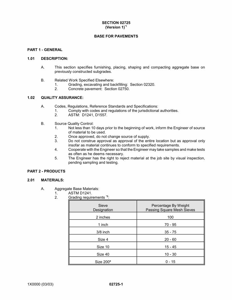
1X0000 (03/03) 02725-1
SECTION 02725(Version 1)*1
BASE FOR PAVEMENTS
PART 1 - GENERAL
1.01 DESCRIPTION:
A. This section specifies furnishing, placing, shaping and compacting aggregate base onpreviously constructed subgrades.
B. Related Work Specified Elsewhere:1. Grading, excavating and backfilling: Section 02320.2. Concrete pavement: Section 02750.
1.02 QUALITY ASSURANCE:
A. Codes, Regulations, Reference Standards and Specifications:1. Comply with codes and regulations of the jurisdictional authorities.2. ASTM: D1241, D1557.
B. Source Quality Control:1. Not less than 10 days prior to the beginning of work, inform the Engineer of source
of material to be used.2. Once approved, do not change source of supply.3. Do not construe approval as approval of the entire location but as approval only
insofar as material continues to conform to specified requirements.4. Cooperate with the Engineer so that the Engineer may take samples and make tests
as often as he deems necessary.5. The Engineer has the right to reject material at the job site by visual inspection,
pending sampling and testing.
PART 2 - PRODUCTS
2.01 MATERIALS:
A. Aggregate Base Materials:1. ASTM D1241.2. Grading requirements *2:
SieveDesignation
Percentage By WeightPassing Square Mesh Sieves
2 inches 100
1 inch 70 - 95
3/8 inch 35 - 75
Size 4 20 - 60
Size 10 15 - 45
Size 40 10 - 30
Size 200* 0 - 15
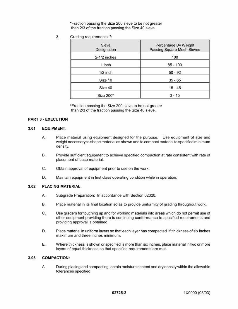
02725-2 1X0000 (03/03)
*Fraction passing the Size 200 sieve to be not greater than 2/3 of the fraction passing the Size 40 sieve.
3. Grading requirements *3:
SieveDesignation
Percentage By WeightPassing Square Mesh Sieves
2-1/2 inches 100
1 inch 85 - 100
1/2 inch 50 - 92
Size 10 35 - 65
Size 40 15 - 45
Size 200* 3 - 15
*Fraction passing the Size 200 sieve to be not greater than 2/3 of the fraction passing the Size 40 sieve.
PART 3 - EXECUTION
3.01 EQUIPMENT:
A. Place material using equipment designed for the purpose. Use equipment of size andweight necessary to shape material as shown and to compact material to specified minimumdensity.
B. Provide sufficient equipment to achieve specified compaction at rate consistent with rate ofplacement of base material.
C. Obtain approval of equipment prior to use on the work.
D. Maintain equipment in first class operating condition while in operation.
3.02 PLACING MATERIAL:
A. Subgrade Preparation: In accordance with Section 02320.
B. Place material in its final location so as to provide uniformity of grading throughout work.
C. Use graders for touching up and for working materials into areas which do not permit use ofother equipment providing there is continuing conformance to specified requirements andproviding approval is obtained.
D. Place material in uniform layers so that each layer has compacted lift thickness of six inchesmaximum and three inches minimum.
E. Where thickness is shown or specified is more than six inches, place material in two or morelayers of equal thickness so that specified requirements are met.
3.03 COMPACTION:
A. During placing and compacting, obtain moisture content and dry density within the allowabletolerances specified.
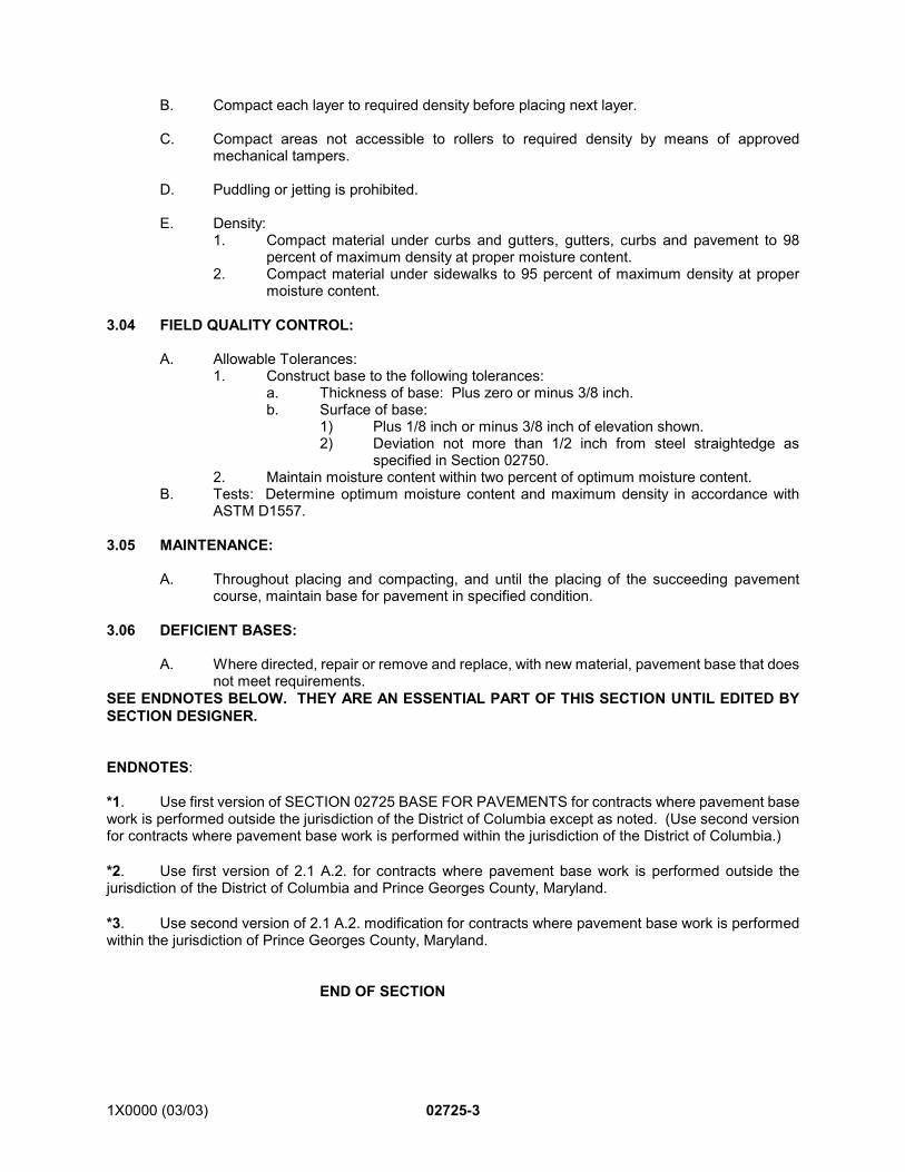
1X0000 (03/03) 02725-3
*1. Use first version of SECTION 02725 BASE FOR PAVEMENTS for contracts where pavement basework is performed outside the jurisdiction of the District of Columbia except as noted. (Use second versionfor contracts where pavement base work is performed within the jurisdiction of the District of Columbia.)
*2. Use first version of 2.1 A.2. for contracts where pavement base work is performed outside thejurisdiction of the District of Columbia and Prince Georges County, Maryland.
*3. Use second version of 2.1 A.2. modification for contracts where pavement base work is performedwithin the jurisdiction of Prince Georges County, Maryland.
END OF SECTION
B. Compact each layer to required density before placing next layer.
C. Compact areas not accessible to rollers to required density by means of approvedmechanical tampers.
D. Puddling or jetting is prohibited.
E. Density:1. Compact material under curbs and gutters, gutters, curbs and pavement to 98
percent of maximum density at proper moisture content.2. Compact material under sidewalks to 95 percent of maximum density at proper
moisture content.
3.04 FIELD QUALITY CONTROL:
A. Allowable Tolerances:1. Construct base to the following tolerances:
a. Thickness of base: Plus zero or minus 3/8 inch.b. Surface of base:
1) Plus 1/8 inch or minus 3/8 inch of elevation shown.2) Deviation not more than 1/2 inch from steel straightedge as
specified in Section 02750.2. Maintain moisture content within two percent of optimum moisture content.
B. Tests: Determine optimum moisture content and maximum density in accordance withASTM D1557.
3.05 MAINTENANCE:
A. Throughout placing and compacting, and until the placing of the succeeding pavementcourse, maintain base for pavement in specified condition.
3.06 DEFICIENT BASES:
A. Where directed, repair or remove and replace, with new material, pavement base that doesnot meet requirements.
SEE ENDNOTES BELOW. THEY ARE AN ESSENTIAL PART OF THIS SECTION UNTIL EDITED BYSECTION DESIGNER.
ENDNOTES:
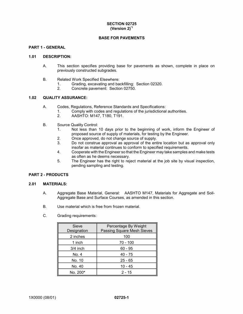
1X0000 (08/01) 02725-1
SECTION 02725(Version 2)*1
BASE FOR PAVEMENTS
PART 1 - GENERAL
1.01 DESCRIPTION:
A. This section specifies providing base for pavements as shown, complete in place onpreviously constructed subgrades.
B. Related Work Specified Elsewhere:1. Grading, excavating and backfilling: Section 02320.2. Concrete pavement: Section 02750.
1.02 QUALITY ASSURANCE:
A. Codes, Regulations, Reference Standards and Specifications:1. Comply with codes and regulations of the jurisdictional authorities.2. AASHTO: M147, T180, T191.
B. Source Quality Control:1. Not less than 10 days prior to the beginning of work, inform the Engineer of
proposed source of supply of materials, for testing by the Engineer.2. Once approved, do not change source of supply.3. Do not construe approval as approval of the entire location but as approval only
insofar as material continues to conform to specified requirements.4. Cooperate with the Engineer so that the Engineer may take samples and make tests
as often as he deems necessary.5. The Engineer has the right to reject material at the job site by visual inspection,
pending sampling and testing.
PART 2 - PRODUCTS
2.01 MATERIALS:
A. Aggregate Base Material, General: AASHTO M147, Materials for Aggregate and Soil-Aggregate Base and Surface Courses, as amended in this section.
B. Use material which is free from frozen material.
C. Grading requirements:
SieveDesignation
Percentage By WeightPassing Square Mesh Sieves
2 inches 1001 inch 70 - 100
3/4 inch 60 - 95No. 4 40 - 75No. 10 25 - 65No. 40 10 - 45
No. 200* 2 - 15
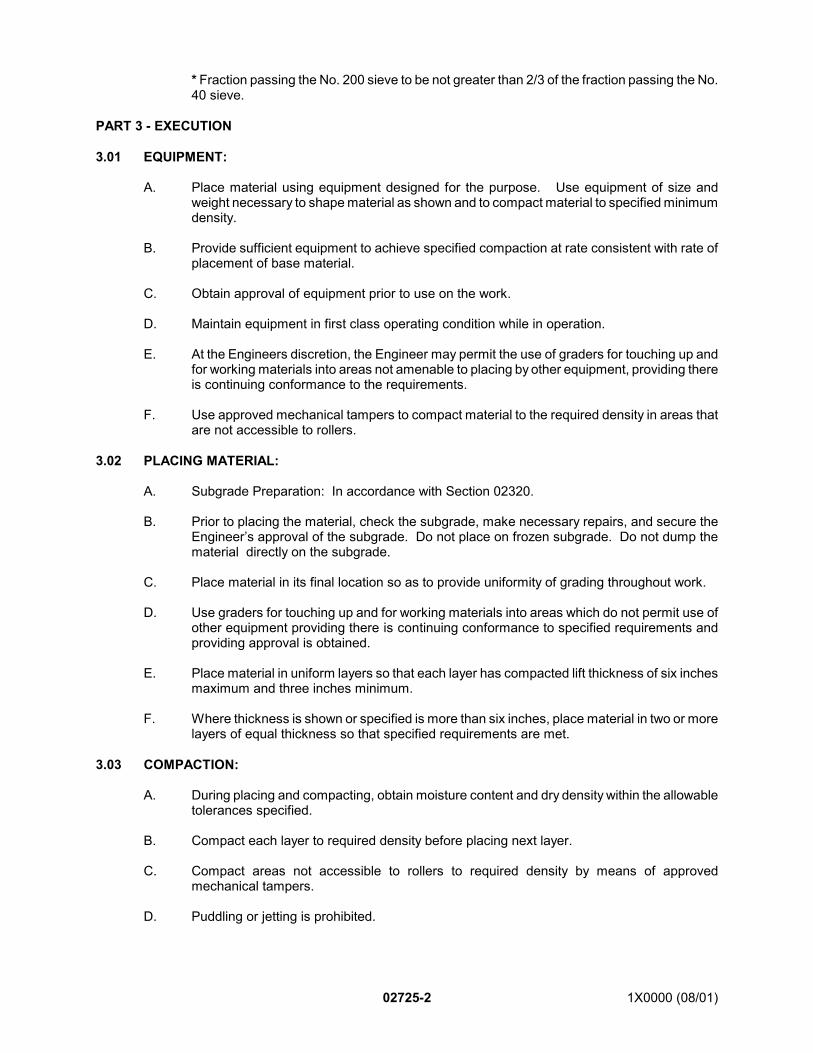
02725-2 1X0000 (08/01)
* Fraction passing the No. 200 sieve to be not greater than 2/3 of the fraction passing the No.40 sieve.
PART 3 - EXECUTION
3.01 EQUIPMENT:
A. Place material using equipment designed for the purpose. Use equipment of size andweight necessary to shape material as shown and to compact material to specified minimumdensity.
B. Provide sufficient equipment to achieve specified compaction at rate consistent with rate ofplacement of base material.
C. Obtain approval of equipment prior to use on the work.
D. Maintain equipment in first class operating condition while in operation.
E. At the Engineers discretion, the Engineer may permit the use of graders for touching up andfor working materials into areas not amenable to placing by other equipment, providing thereis continuing conformance to the requirements.
F. Use approved mechanical tampers to compact material to the required density in areas thatare not accessible to rollers.
3.02 PLACING MATERIAL:
A. Subgrade Preparation: In accordance with Section 02320.
B. Prior to placing the material, check the subgrade, make necessary repairs, and secure theEngineer’s approval of the subgrade. Do not place on frozen subgrade. Do not dump thematerial directly on the subgrade.
C. Place material in its final location so as to provide uniformity of grading throughout work.
D. Use graders for touching up and for working materials into areas which do not permit use ofother equipment providing there is continuing conformance to specified requirements andproviding approval is obtained.
E. Place material in uniform layers so that each layer has compacted lift thickness of six inchesmaximum and three inches minimum.
F. Where thickness is shown or specified is more than six inches, place material in two or morelayers of equal thickness so that specified requirements are met.
3.03 COMPACTION:
A. During placing and compacting, obtain moisture content and dry density within the allowabletolerances specified.
B. Compact each layer to required density before placing next layer.
C. Compact areas not accessible to rollers to required density by means of approvedmechanical tampers.
D. Puddling or jetting is prohibited.
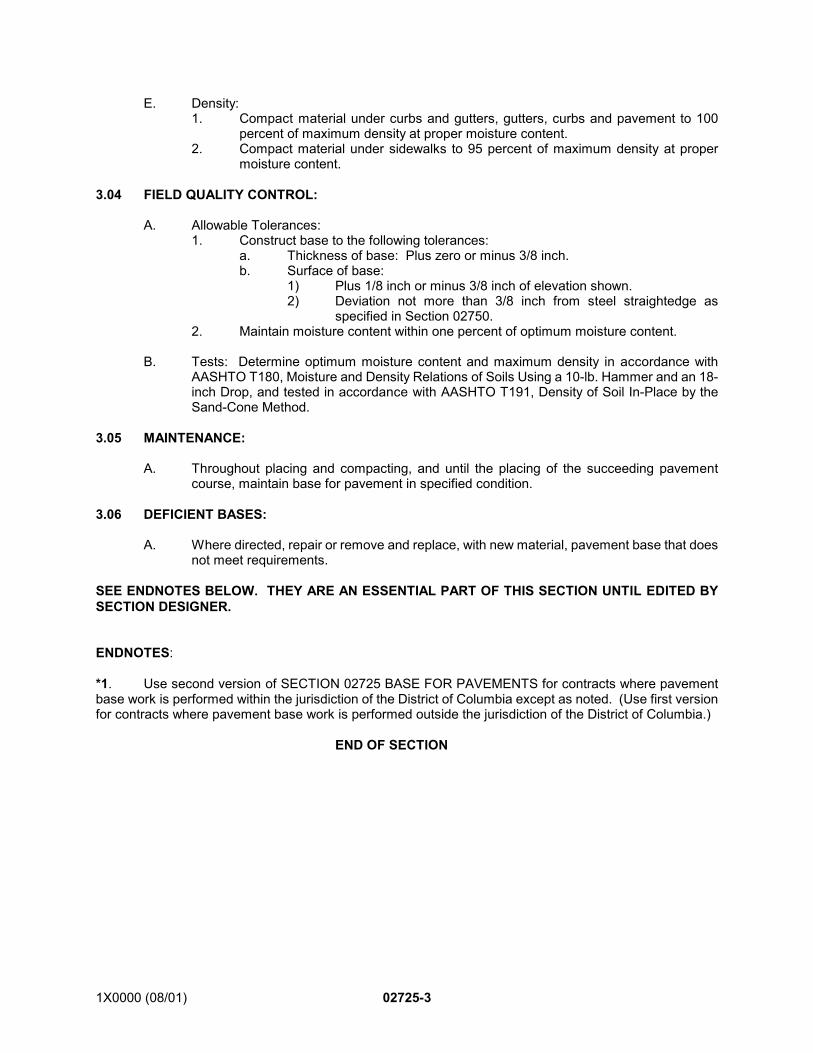
1X0000 (08/01) 02725-3
*1. Use second version of SECTION 02725 BASE FOR PAVEMENTS for contracts where pavementbase work is performed within the jurisdiction of the District of Columbia except as noted. (Use first versionfor contracts where pavement base work is performed outside the jurisdiction of the District of Columbia.)
END OF SECTION
E. Density: 1. Compact material under curbs and gutters, gutters, curbs and pavement to 100
percent of maximum density at proper moisture content.2. Compact material under sidewalks to 95 percent of maximum density at proper
moisture content.
3.04 FIELD QUALITY CONTROL:
A. Allowable Tolerances:1. Construct base to the following tolerances:
a. Thickness of base: Plus zero or minus 3/8 inch.b. Surface of base:
1) Plus 1/8 inch or minus 3/8 inch of elevation shown.2) Deviation not more than 3/8 inch from steel straightedge as
specified in Section 02750.2. Maintain moisture content within one percent of optimum moisture content.
B. Tests: Determine optimum moisture content and maximum density in accordance withAASHTO T180, Moisture and Density Relations of Soils Using a 10-lb. Hammer and an 18-inch Drop, and tested in accordance with AASHTO T191, Density of Soil In-Place by theSand-Cone Method.
3.05 MAINTENANCE:
A. Throughout placing and compacting, and until the placing of the succeeding pavementcourse, maintain base for pavement in specified condition.
3.06 DEFICIENT BASES:
A. Where directed, repair or remove and replace, with new material, pavement base that doesnot meet requirements.
SEE ENDNOTES BELOW. THEY ARE AN ESSENTIAL PART OF THIS SECTION UNTIL EDITED BYSECTION DESIGNER.
ENDNOTES:
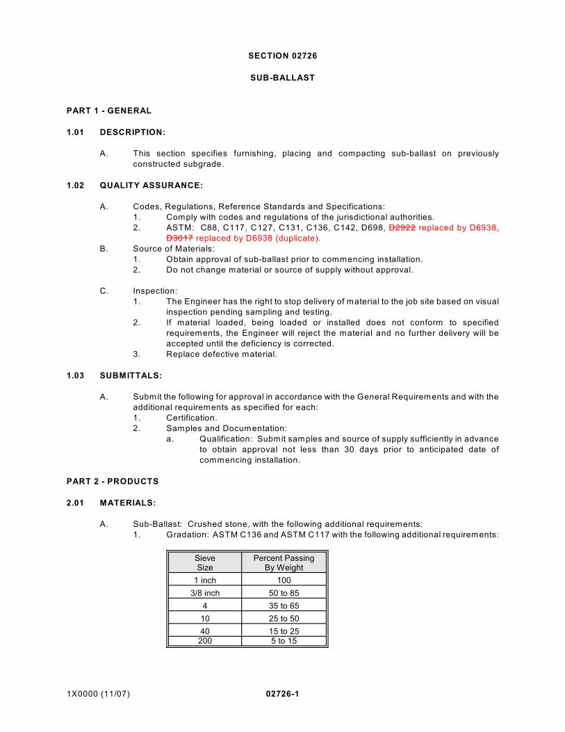
1X0000 (11/07) 02726-1
SECTION 02726
SUB-BALLAST
PART 1 - GENERAL
1.01 DESCRIPTION:
A. This section specifies furnishing, placing and compacting sub-ballast on previously
constructed subgrade.
1.02 QUALITY ASSURANCE:
A. Codes, Regulations, Reference Standards and Specifications:
1. Comply with codes and regulations of the jurisdictional authorities.
2. ASTM: C88, C117, C127, C131, C136, C142, D698, D2922 replaced by D6938,
D3017 replaced by D6938 (duplicate).
B. Source of Materials:
1. Obtain approval of sub-ballast prior to commencing installation.
2. Do not change material or source of supply without approval.
C. Inspection:
1. The Engineer has the right to stop delivery of material to the job site based on visual
inspection pending sampling and testing.
2. If material loaded, being loaded or installed does not conform to specified
requirements, the Engineer will reject the material and no further delivery will be
accepted until the deficiency is corrected.
3. Replace defective material.
1.03 SUBMITTALS:
A. Submit the following for approval in accordance with the General Requirements and with the
additional requirements as specified for each:
1. Certification.
2. Samples and Documentation:
a. Qualification: Submit samples and source of supply sufficiently in advance
to obtain approval not less than 30 days prior to anticipated date of
commencing installation.
PART 2 - PRODUCTS
2.01 MATERIALS:
A. Sub-Ballast: Crushed stone, with the following additional requirements:
1. Gradation: ASTM C136 and ASTM C117 with the following additional requirements:
SieveSize
Percent PassingBy Weight
1 inch 100
3/8 inch 50 to 85
4 35 to 65
10 25 to 50
40 15 to 25200 5 to 15
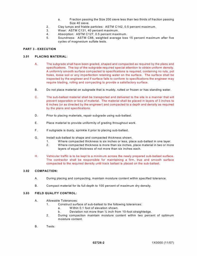
02726-2 1X0000 (11/07)
a. Fraction passing the Size 200 sieve less than two thirds of fraction passing
Size 40 sieve.
2. Clay lumps and friable particles: ASTM C142, 0.5 percent maximum.
3. W ear: ASTM C131, 40 percent maximum.
4. Absorption: ASTM C127, 0.5 percent maximum.
5. Soundness: ASTM C88, weighted average loss 15 percent maximum after five
cycles of magnesium sulfate tests.
PART 3 - EXECUTION
3.01 PLACING MATERIAL:
A. The subgrade shall have been graded, shaped and compacted as required by the plans and
specifications. The top of the subgrade required special attention to obtain uniform density.
A uniformly smooth surface compacted to specifications is required, containing no ruts, pot
holes, loose soil or any imperfection retaining water on the surface. The surface shall be
inspected by the engineer and if surface fails to conform to specifications the engineer may
require blading, rolling and compacting to provide a satisfactory surface.
B. Do not place material on subgrade that is muddy, rutted or frozen or has standing water.
C. The sub-ballast material shall be transported and delivered to the site in a manner that will
prevent separation or loss of material. The material shall be placed in layers of 3 inches to
6 inches (or as directed by the engineer) and compacted to a depth and density as required
by the plans and specifications.
D. Prior to placing materials, repair subgrade using sub-ballast.
E. Place material to provide uniformity of grading throughout work.
F. If subgrade is dusty, sprinkle it prior to placing sub-ballast.
G. Install sub-ballast to shape and compacted thickness shown.
1. W here compacted thickness is six inches or less, place sub-ballast in one layer.
2. W here compacted thickness is more than six inches, place material in two or more
layers of equal thickness of not more than six inches each.
H. Vehicular traffic is to be kept to a minimum across the newly prepared sub-ballast surface.
The contractor shall be responsible for maintaining a firm, true and smooth surface
compacted to the required density until track ballast is placed on the sub-ballast.
3.02 COMPACTION:
A. During placing and compacting, maintain moisture content within specified tolerance.
B. Compact material for its full depth to 100 percent of maximum dry density.
3.03 FIELD QUALITY CONTROL:
A. Allowable Tolerances:
1. Construct surface of sub-ballast to the following tolerances:
a. W ithin 0.1 foot of elevation shown.
b. Deviation not more than ½ inch from 10-foot straightedge.
2. During compaction maintain moisture content within two percent of optimum
moisture content.
B. Tests:
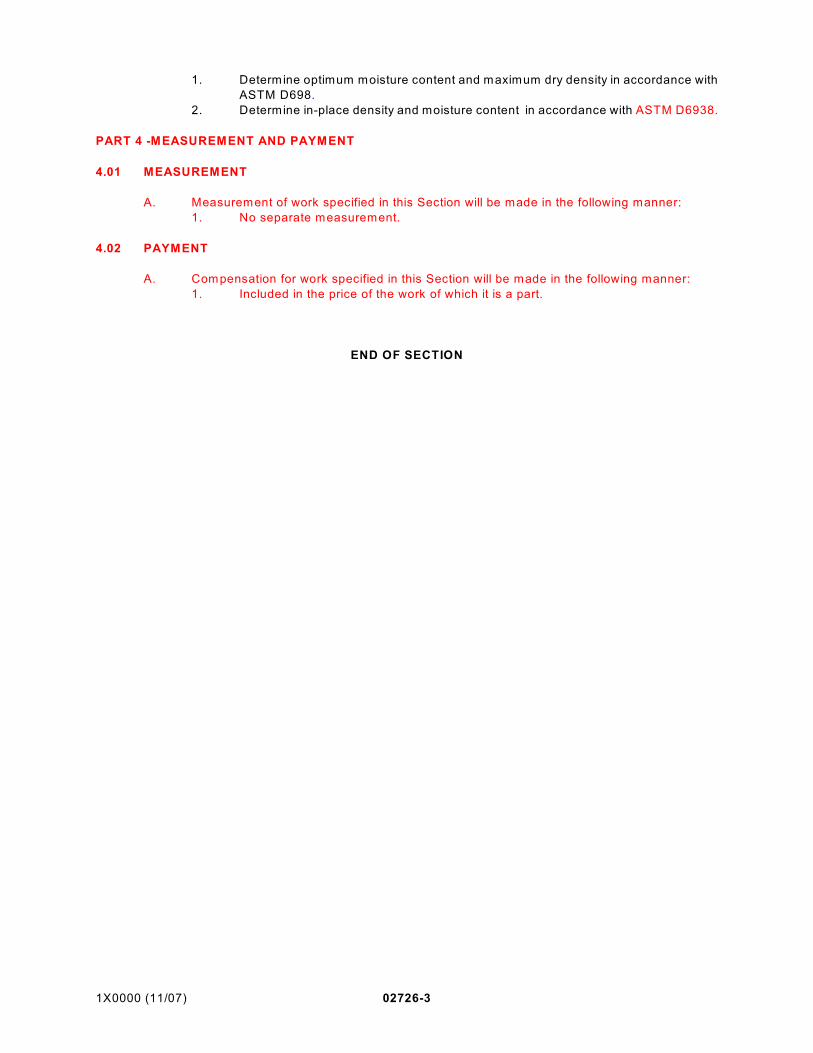
1X0000 (11/07) 02726-3
1. Determine optimum moisture content and maximum dry density in accordance with
ASTM D698.
2. Determine in-place density and moisture content in accordance with ASTM D6938.
PART 4 -MEASUREMENT AND PAYMENT
4.01 MEASUREMENT
A. Measurement of work specified in this Section will be made in the following manner:
1. No separate measurement.
4.02 PAYMENT
A. Compensation for work specified in this Section will be made in the following manner:
1. Included in the price of the work of which it is a part.
END OF SECTION

1X0000 (11/07) 02727-1
SECTION 02727
BALLAST
PART 1 - GENERAL
1.01 DESCRIPTION:
A. This section specifies furnishing mineral aggregate for use as ballast for ballasted track
construction.
1.02 QUALITY ASSURANCE:
A. Codes, Regulations, Reference Standards and Specifications:
1. Comply with codes and regulations of the jurisdictional authorities.
2. CE: CRD-C 119.
3. ASTM: C88, C117, C127, C131, C 136, C142, C535.
4. AREMA: Chapter 1-2-1, (Volume 1), latest edition.
B. Source:
1. Obtain approval prior to installation.
2. Do not change ballast or source without approval.
C. Inspection:
1. The Engineer has the right to stop delivery of material to job site by visual inspection,
pending sampling and testing.
2. If material loaded, being loaded or installed does not conform to specified
requirements, the Engineer will reject the material and no further delivery will be
accepted until the deficiency has been corrected.
3. Replace defective material.
D. Testing and Sampling:
1. Subject ballast to specified tests, except gradation test, at an approved independent
testing facility.
2. Conduct testing, except gradation test, to determine if ballast meets specified
requirements.
3. Visual inspection and gradation testing will be made by the Engineer:
a. 30 days prior to initial delivery.
b. Immediately prior to placement on the track bed.
c. Each 4,000 tons of ballast delivered.
W MATA, or its representatives, reserve the right to visit the producers facility during
usual business hours unscheduled to a) observe sampling and testing procedures,
b) obtain samples of the prepare material being produced and shipped, and c)
review plant inspection methods, quality control procedures, equipment and examine
test results of current and previous tests.
4. Prior to installation, the supplier shall provide the Engineer with certified results of
ballast quality and gradation as conducted by a testing laboratory accepted by the
Engineer. The supplier shall receive approval of the Engineer for the Testing
Laboratory prior to performing the aforementioned tests.
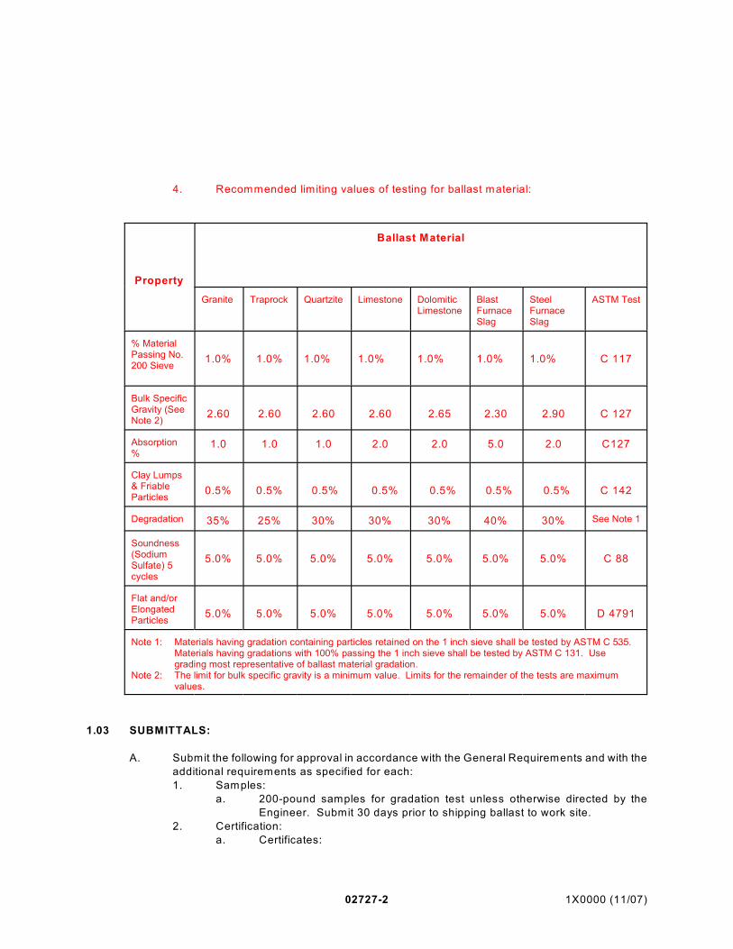
02727-2 1X0000 (11/07)
4. Recommended limiting values of testing for ballast material:
Property
Ballast Material
Granite Traprock Quartzite Limestone DolomiticLimestone
BlastFurnaceSlag
SteelFurnaceSlag
ASTM Test
% MaterialPassing No.200 Sieve
1.0% 1.0% 1.0% 1.0% 1.0% 1.0% 1.0% C 117
Bulk SpecificGravity (SeeNote 2)
2.60 2.60 2.60 2.60 2.65 2.30 2.90 C 127
Absorption%
1.0 1.0 1.0 2.0 2.0 5.0 2.0 C127
Clay Lumps& FriableParticles
0.5% 0.5% 0.5% 0.5% 0.5% 0.5% 0.5% C 142
Degradation 35% 25% 30% 30% 30% 40% 30% See Note 1
Soundness(SodiumSulfate) 5cycles
5.0% 5.0% 5.0% 5.0% 5.0% 5.0% 5.0% C 88
Flat and/orElongatedParticles
5.0% 5.0% 5.0% 5.0% 5.0% 5.0% 5.0% D 4791
Note 1: Materials having gradation containing particles retained on the 1 inch sieve shall be tested by ASTM C 535. Materials having gradations with 100% passing the 1 inch sieve shall be tested by ASTM C 131. Usegrading most representative of ballast material gradation.
Note 2: The limit for bulk specific gravity is a minimum value. Limits for the remainder of the tests are maximumvalues.
1.03 SUBMITTALS:
A. Submit the following for approval in accordance with the General Requirements and with the
additional requirements as specified for each:
1. Samples:
a. 200-pound samples for gradation test unless otherwise directed by the
Engineer. Submit 30 days prior to shipping ballast to work site.
2. Certification:
a. Certificates:
1X0000 (11/07) 02727-3
1) Submit source of supply sufficiently in advance to obtain approval
not less than 30 days prior to anticipated date of commencing
installation.
b. At time of delivery, submit certificates attesting that material furnished is
typical of that tested and conforms to specified requirements.
3. Certified test results:
a. Submit not less than two weeks prior to shipping ballast to work site.
4. Handling Procedures: Submit the proposed method of handling.
1.04 PRODUCT DELIVERY, HANDLING, AND STORAGE:
A. Deliver, handle, and store the material by methods which prevent damage, fouling and
segregation.
B. The aggregate production facility shall be of such design to permit production and or blending
without excessive working of the materials and the facility must be approved by the
purchaser.
C. Blending, stockpiling and other production and handling operations shall be managed by the
producer to minimize segregation of the finished product. Stockpiling operations shall be
minim ize as practical the breakage or excessive fall in stockpiling operations and the
movement of wheeled or tracked machines over stockpiled materials shall be limited.
D. Processed ballast shall be washed and/or rescreened as necessary to remove fine particle
contamination as defined by the specification or as directed by W MATA prior to stockpiling
in operations using stockpiles or immediately prior to loading operations.
E. The following are prohibited:
1. Storage of ballast in cone-shaped piles.
2. Subjecting ballast to repeated passes of equipment over same levels in stockpile
area.
PART 2 - PRODUCTS
2.01 MATERIALS:
A. Ballast: Crushed stone from diabase rock, hard, strong, angular, durable, free from injurious
amounts of deleterious substances, with the following additional requirements:
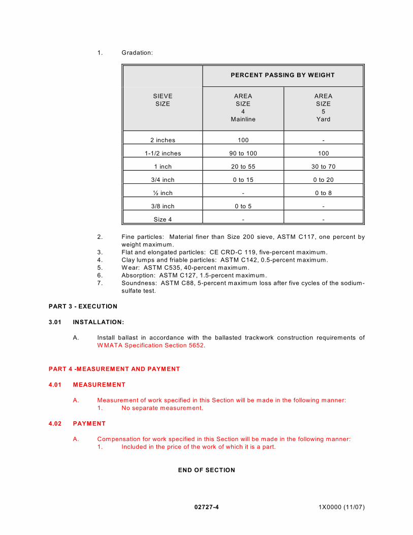
02727-4 1X0000 (11/07)
1. Gradation:
PERCENT PASSING BY WEIGHT
SIEVE
SIZE
AREA
SIZE
4
Mainline
AREA
SIZE
5
Yard
2 inches 100 -
1-1/2 inches 90 to 100 100
1 inch 20 to 55 30 to 70
3/4 inch 0 to 15 0 to 20
½ inch - 0 to 8
3/8 inch 0 to 5 -
Size 4 - -
2. Fine particles: Material finer than Size 200 sieve, ASTM C117, one percent by
weight maximum.
3. Flat and elongated particles: CE CRD-C 119, five-percent maximum.
4. Clay lumps and friable particles: ASTM C142, 0.5-percent maximum.
5. W ear: ASTM C535, 40-percent maximum.
6. Absorption: ASTM C127, 1.5-percent maximum.
7. Soundness: ASTM C88, 5-percent maximum loss after five cycles of the sodium-
sulfate test.
PART 3 - EXECUTION
3.01 INSTALLATION:
A. Install ballast in accordance with the ballasted trackwork construction requirements of
W MATA Specification Section 5652.
PART 4 -MEASUREMENT AND PAYMENT
4.01 MEASUREMENT
A. Measurement of work specified in this Section will be made in the following manner:
1. No separate measurement.
4.02 PAYMENT
A. Compensation for work specified in this Section will be made in the following manner:
1. Included in the price of the work of which it is a part.
END OF SECTION

1X0000 (03/03) 02740-1
SECTION 02740(Version 1)*1
BITUMINOUS PAVEMENT
PART 1 - GENERAL
1.01 DESCRIPTION:A. This section specifies providing asphaltic surface, binder and base courses on prepared
subgrade or previously constructed base course in conformance with sections, lines andgrades shown.
B. Related Work Specified Elsewhere:1. Base for pavements: Section 02725.
1.02 SUBMITTALS:
A. Submit the following for approval in accordance with the General Requirements and with theadditional requirements as specified for each:1. Certification:
a. For each delivery of asphaltic material, submit certificate stating type andamount of asphalt and results of specified tests.
2. Documentation:a. Job-mix formula:
1) For each mix to be supplied submit job-mix formula based onexpected production averages.
2) In formula establish:a) Weight percent of total aggregate and of aggregate finer
than each required sieve size.b) Weight percent of total mix of asphalt cement.c) Temperature of mix when placed.
3) Maintain job-mix formula once approved.b. Weight ticket: For each load of bituminous mixture delivered to the site,
submit weight ticket showing the following:1) Mix type.2) Mix temperature.3) Identification of the truck.4) Tare weight of truck.5) Loaded weight of truck.6) Net weight of load.7) Time of leaving mix plant.8) Signature of the Engineer's plant representative.
1.03 QUALITY ASSURANCE:
A. Codes, Regulations, Reference Standards and Specifications:1. Comply with codes and regulations of the jurisdictional authorities.2. MSHA. *23. VDOT. *34. AASHTO: M6, M29, M43, M45, M76, M79, M140, M156, M208, T30, T164, T165,
T168. *45. AASHTO: M6, M29, M43, M45, M76, M79, M82, M140, M156, M208, T30, T164,
T165, T168. *56. ASTM: D2950, D3515. *67. ASTM: D3515. *7
02740-2 1X0000 (03/03)
B. Sources of Supply:1. Not less than 20 days prior to beginning the work, inform the Engineer of the source
of the materials to be used and obtain approval.2. Once approved, do not change source of supply.3. Do not construe approval as approval of entire location but as approval only insofar
as material continues to meet specified requirements.4. Maintain quality of material. Material may be sampled and tested by the Engineer
as often as the Engineer deems necessary.5. The Engineer has the right to reject material at the job site by visual inspection
pending sampling and testing.
1.04 PRODUCT DELIVERY, STORAGE AND HANDLING:
A. Delivery Trucks:1. For transporting bituminous, mixtures use trucks which show no leakage of oil or
grease, have solid metal dump-type beds which are clean and smooth with tightfitting rear gate to prevent loss of materials in transit.
2. Prior to loading, spray inside surface of truck beds with minimum amount ofapproved thin oil or mixture of lime and water proportioned 50 gallons of water to 100pounds of lime necessary to prevent adhesion of the mixture. Do not use kerosene,gasoline or excessive amount of oil.
3. Equip trucks with coverings to protect loads from weather and with suitable insulationto prevent undue heat loss during transit at temperatures below 40F.
B. Weighing of Bituminous Mixtures:1. Provide approved truck scales having both dial and automatic printer or use public
scales.2. Use scales complying with applicable laws, ordinances and regulations governing
use of scales.3. Have scales tested and sealed by authorized public official as often as directed to
ensure their accuracy.4. At least once a week, check tare weight of each truck with full load of fuel and fitted
with its equipment.
1.05 JOB CONDITIONS:
A. Environmental Requirements:1. Do not place bituminous pavement on wet surfaces.2. Place bituminous pavement when temperature of air and base exceed 40F.
PART 2 - PRODUCTS
2.01 MATERIALS:
A. Asphalt Cement: AASHTO ___________________. *8
B. Asphalt Cement: AASHTO _______________, Table 2, with no requirement for maximumloss on heating. *9
C. Cut-Back Asphalt for Prime Coat: Equivalent to AASHTO __________________. *10
D. Cut-Back Asphalt, AASHTO M82, __________________. Note 4 option applies. *11

1X0000 (03/03) 02740-3
E. Emulsified Asphalt for Tack Coat: SS-1, SS-1h, CSS-1, or CSS-1h, diluted one-part waterto one-part emulsified asphalt. Prior to dilution, emulsified asphalt to comply with AASHTOM140 or AASHTO M208. Apply at rate of 0.05 to 0.15 gallons per square yard.
F. Aggregate: Coarse and fine aggregate to be free from substantial portions of serpentine ortalc materials or carbonate aggregates containing less than 25 percent by weight insolubleresidue retained between Size 10 and Size 200 sieves as determined by leaching sampleswith 6N hydrochloric acid.1. Coarse aggregate: Crushed stone, AASHTO M79 and AASHTO M76 except for
grading. Weight loss not to exceed 15 percent by weight when subjected to fivealterations of magnesium sulfate soundness test.
2. Fine aggregate for hot asphaltic concrete: Consisting of one or a combination of thefollowing materials:a. Material conforming to AASHTO M6 with the following additional
requirements:1) When the material is subjected to five alternations of the
magnesium sulfate soundness test, weighted loss not exceeding 12percent by weight; amount of deleterious substances not exceedingfollowing maximum permissible percent limits by weight:a) Clay lumps: 0.5.b) Coal and lignite: 0.25.c) Material passing size 200 sieve: 3.0.d) Other deleterious substances, such as shale, alkali, mica,
coated grains, soft and flaky particles: 2.0.b. Material conforming to specified requirements for No. 10 coarse aggregate
in accordance with AASHTO M43.3. Fine aggregate for sheet asphalt binder: AASHTO M45, with the following additional
requirements:
SieveDesignation
Percentage By Weight PassingSquare Mesh Sieves
8 100
50 15 - 40
100 0 - 10
200 0 - 5
4. Fine aggregate for sheet asphalt surface: AASHTO M29, with the followingadditional requirements:
SieveDesignation
Percentage By Weight PassingSquare Mesh Sieves
4 100
10 95 - 100
40 55 - 80
80 15 - 40

02740-4 1X0000 (03/03)
5. Mineral filler:
SieveDesignation
Percentage By Weight PassingSquare Mesh Sieves
30 100
50 95 - 100
200 70 - 100
2.02 MIXES:
A. Provide mixes in accordance with ASTM D3515 and as specified.
B. Proportion constituents of job mixes within limits specified in Table 02740-1.
C. Submit mixes as directed for evaluation of job-mix formula, with bulk specific gravitydetermined in accordance with AASHTO T165.
2.03 TEMPERATURE OF MIXES:
A. Maintain temperature of mixes within plus-or-minus 25F of that given in job-mix formula.Temperature ranges as specified in Table 02740-2.
PART 3 - EXECUTION
3.01 EQUIPMENT:
A. Equipment for Preparing Bituminous Material:1. Use bituminous paving material prepared in mixing plant conforming to AASHTO
M156.
B. Equipment for Spreading and Finishing Bituminous Material:1. Use equipment capable of placing material at widths ranging from eight to twelve
feet by increments of one foot and at varying thickness.2. Use machines which spread bituminous mixture without tearing surface. Achieve
finish that is smooth, true to cross section, uniform in density and texture and freefrom hollows, corrugations and other irregularities.
C. Equipment for Compacting:1. Provide approved equipment capable of compacting materials to specified Marshall
density.
3.02 BASE PREPARATION:
A. Prior to placing bituminous mixture, check line, grade and cross section of underlying course.Repair defective areas.
B. Have base approved, prior to placement of surface course.
C. Aggregate and Soil Aggregate Bases:1. Apply cut-back asphalt primer at rate of 0.2 to 0.5 gallons per square yard when
base is damp but with no standing water.

1X0000 (03/03) 02740-5
2. Allow 24 hours for base to entirely absorb primer. Blot excess primer with justenough sand to prevent pickup under traffic. Sweep loose sand from base beforeplacing base course.
D. Portland Cement Concrete, Bituminous and Brick Pavement Bases:1. Apply tack coat using equipment designed for that purpose.2. Apply tack coat uniformly to clean dry base at rate of 0.05 to 0.15 gallons per square
yard.3. Ensure that surface has cured and is satisfactorily tacky before placing mix.
E. Immediately prior to placing mix, apply thin coat of hot asphalt cement to contact surfacesof curbs, gutters, manholes and similar structures.
3.03 PLACING MIX:
A. Place base course mixture in one or more lifts with asphalt paver or spreader to providenominal compacted thickness as shown. Place surface course mixture with asphalt paverto provide nominal compacted thickness as shown. Minimum lift thickness at least two timesmaximum particle size. Maximum lift thickness to be that which can be demonstrated to belaid in a single lift and compacted to required uniform density and smoothness. Placematerial in continuous operation. Correct irregularities before final compaction of mixture.
B. If equipment being used produces tracks, pulling, indented areas or other permanentblemishes in material being spread, remove such equipment from site and substitute otherapproved spreading and finishing equipment.
C. Do not permit direction of movement of paving equipment to be changed by turning on newlycompleted base, binder or surface courses.
D. Adjacent to headers, gutters, manholes and similar structures, place surface course so thatfinished surface is 1/4-inch above edge of structure.
E. When the Engineer considers it impractical to place mix with two machines, one machine willbe permitted. Treat joints created by such operation as cold joints.
F. Rake joints to eliminate seams between lane passes.
3.04 COMPACTION:
A. Compact immediately after placing. Initial rolling with steel-wheel tandem roller, steel three-wheel roller, vibratory roller, or pneumatic-tire roller following paver as closely as possible,oriented with drive wheel closest to paver. If intermediate rolling is needed, use pneumatic-tire roller immediately behind initial rolling. Final rolling to eliminate marks from previousrolling. Use vibrating plate compactor or hand tamper to achieve thorough compaction inareas too small for roller. Keep steel wheel rollers wet while rolling.
3.05 COLD JOINTS:
A. Longitudinal: Apply tack coat to cold material before joining new work.
B. Transverse: Place bulkhead full depth of course or cut back minimum of three inches fromsloping surface with masonry saw. Apply tack coat to cold material.
3.06 BULKHEADS:

02740-6 1X0000 (03/03)
A. Where placement of mix is to be discontinued for such period of time that material will fallbelow specified street temperature, place suitable bulkhead.
B. Construct cold joint as specified when work is resumed.
3.07 HANDWORK:
A. When approved, perform bituminous paving work by hand in areas inaccessible to machines.
B. Undertake handwork using equipment designed and approved for purpose.
C. Perform handwork so that resulting paving meets specified requirements.
3.08 FIELD QUALITY CONTROL:
A. Allowable Tolerances:1. Thickness: Place bituminous pavement to within tolerance of plus-or-minus 1/8 inch
of thickness shown.2. Surfaces: Construct surfaces to the following tolerances:
a. Base courses to within plus-or-minus 3/8 inch of elevation shown.b. Surface courses to within plus-or-minus 3/16 inch of elevation shown.c. Surfaces to deviate no more than 1/4 inch in the length of 10-foot steel
straightedge, not cumulative.d. During compacting, screed surface using straightedge as specified in
Section 02750. Adjust rolling procedures so that tolerances are met.3. Densities required:
a. Base courses: 94 percent of Marshall density. *12
b. Base courses: 95 percent of Marshall density. *13
c. Surface courses: 96 percent of Marshall density.
B. Testing:1. Mixes:
a. During course of the work submit mixes as directed for testing of gradationand bitumen content in accordance with AASHTO T30 and AASHTO T164on random samples selected in accordance with AASHTO T168.
2. Determine density of base and surface courses by one of the following methods:a. Test base and surface courses for density and thickness with a nuclear
density meter in accordance with ASTM D2950. *14
1) Compute average thickness of base and surface courses fromaverage density and weight per square yard of paving mixtureactually used as follows:
t = W 0.75 d
Where:
t = pavement thickness, in inches.
W = average weight of base or surface mixtureactually used, pounds per square yard.
d = compacted density of base or surfacecourse as measured by the nuclear device,pounds per cubic foot.

1X0000 (03/03) 02740-7
0.75 = constant.b. Not used. *15
c. Test base and surface courses for density by taking test cores at designatedlocations for testing by the Engineer, number of cores not exceeding onecore per 500 square yards of bituminous pavements or two cores per shift,whichever is greater. *16
1) Wherever deficient pavement is discovered take such additionalcores as directed.
2) Repair core holes promptly using the same mix that was cored;where cores are taken through both base course and surfacecourse simultaneously, use surface course mix for repair work.
d. Test base and surface courses for density by taking test cores at designatedlocations for testing by the Engineer, number of cores not exceeding onecore per 500 square yards of bituminous pavements or three cores per shift,whichever is greater. *17
1) Wherever deficient pavement is discovered take such additionalcores as directed.
2) Repair core holes promptly using the same mix that was cored;where cores are taken through both base course and surfacecourse simultaneously, use surface course mix for repair work.
3.09 PROTECTION OF BITUMINOUS PAVEMENT:
A. Obtain approval for use of pavement by public and construction traffic.
B. Do not permit traffic to cross uncompleted longitudinal joints.
3.10 DEFICIENT PAVEMENT:
A. Where directed, replace with new material or repair bituminous pavement that does not meetspecified requirements.
B. Pavement is considered deficient if the densities of three cores from one day's work arebelow 95 percent or if the density of one core is below 90 percent. *18

02740-8 1X0000 (03/03)
TABLE 02740-1 CONSTITUENT PROPORTIONS *19
GRADING OF TOTAL AGGREGATE (COARSE, FINE, MINERALFILLER: AS NECESSARY) AMOUNTS FINER THAN
LABORATORY SIEVE (SQUARE OPENING) WEIGHT PERCENT
SIEVESHEET
ASPHALTHOT ASPHALTIC
CONCRETE* JOB-MIX FORMULA
TOLERANCE:
BINDER SURFACE BINDER SURFACE ALL MIXES
1 inch - - - - 100 - - +7
3/4 inch - - - - 90 - 100 - - +7
1/2 inch 100 - - - - 100 +7
3/8 inch 85 - 100 - - 60 - 85 85 - 100 +7
No. 4 35 - 55 100 45 - 65 55 - 80 +7
No. 10 20 - 35 95 - 100 30 - 50 40 - 65 +6
No. 40 - - 55 - 92 10 - 25 10 - 30 +6
No. 80 - - 20 - 60 3 - 15 3 - 15 +4
No. 200 0 - 5 9 - 20 2 - 8 2 - 8 +3
ASPHALTIC CEMENT, WEIGHT PERCENT OF TOTAL MIXTURE
4.0 - 7.0 8.5 - 11.5 5.0 - 8.0 5.0 - 8.0 +0.5
* Notwithstanding tolerances, supply mixes within specified grading limits.

1X0000 (03/03) 02740-9
TABLE 02740-1 CONSTITUENT PROPORTIONS *20
GRADING OF TOTAL AGGREGATE (COARSE, FINE, MINERALFILLER: AS NECESSARY) AMOUNTS FINER THAN
LABORATORY SIEVE (SQUARE OPENING) WEIGHT PERCENT
SIEVE
HOT ASPHALTICCONCRETE
* JOB-MIX FORMULATOLERANCE:
P.G. CO. P2BASE
P.G. CO. SNSURFACE
ALLMIXES
1-1/2 inch 100 - - +7
1 inch 93 - 100 - - +7
3/4 inch 82 - 95 100 +7
3/8 inch 60 - 78 90 - 100 +7
# 4 40 - 58 65 - 85 +7
# 8 - - 48 - 68 +4
# 10 23 - 40 - - +4
# 16 - - 34 - 54 +4
# 20 14 - 29 - - +4
# 30 - - 22 - 42 +4
# 40 9 - 21 - - +4
# 50 - - 10 - 32 +4
# 80 5 - 13 - - +4
# 100 - - 5 - 24 +4
# 200 2 - 6 3 - 12 +2
ASPHALT CEMENT, WEIGHT PERCENT OF TOTAL MIXTURE
4.5 - 6.5 5.0 - 11.0 +0.4
* Notwithstanding tolerances, supply mixes within specified grading limits.

02740-10 1X0000 (03/03)
*1. Use first version of SECTION 02740 BITUMINOUS PAVEMENT for contracts where bituminouspavement work is performed outside the jurisdiction of the District of Columbia except as noted. (Use secondversion for contracts where bituminous pavement work is performed within the jurisdiction of the District ofColumbia.)
*2. Use first version of 1.3 A.2. for contracts where bituminous pavement work is performed within thejurisdiction of the State of Maryland.
*3. Use second version of 1.3 A.2. for contracts where bituminous pavement work is performed withinthe jurisdiction of the Commonwealth of Virginia.
*4. Use first version of 1.3 A.3. for contracts where bituminous pavement work is performed outside thejurisdiction of the District of Columbia and Prince Georges County, Maryland.
*5. Use second version of 1.3 A.3. modification for contracts where bituminous pavement work isperformed within the jurisdiction of Prince Georges County, Maryland.
*6. Use first version of 1.3 A.4. for contracts where bituminous pavement work is performed outside thejurisdiction of the District of Columbia and Prince Georges County, Maryland.
*7. Use second version of 1.3 A.4. modification for contracts where bituminous pavement work isperformed within the jurisdiction of Prince Georges County, Maryland.
*8. Use first version of 2.1 A. for contracts where bituminous pavement work is performed outside thejurisdiction of the District of Columbia and Prince Georges County, Maryland
TABLE 02740-2 MIX TEMPERATURE RANGES
TEMPERATURES, DEGREES F
MIX PLANT STREET
AGGREGATE ASPHALT CEMENT TOTAL MIX
SheetAsphaltBinder
250 - 325 250 - 325 250 - 325 250 - 325
SheetAsphaltSurface
300 - 375 250 - 350 300 - 375 275 - 350
HotAsphalticConcrete
250 - 325 250 - 325 250 - 325 250 - 325
SEE ENDNOTES BELOW. THEY ARE AN ESSENTIAL PART OF THIS SECTION UNTIL EDITED BYSECTION DESIGNER.
ENDNOTES:

1X0000 (03/03) 02740-11
*9. Use second version of 2.1 A. modification for contracts where bituminous pavement work isperformed within the jurisdiction of Prince Georges County, Maryland.
*10. Use first version of 2.1 B. for contracts where bituminous pavement work is performed outside thejurisdiction of the District of Columbia and Prince Georges County, Maryland.
*11. Use second version of 2.1 B. modification for contracts where bituminous pavement work isperformed within the jurisdiction of Prince Georges County, Maryland.
*12. Use first version of 3.8 A.3.a. for contracts where bituminous pavement work is performed outsidethe jurisdiction of the District of Columbia and Prince Georges County, Maryland.
*13. Use second version of 3.8 A.3.a. modification for contracts where bituminous pavement work isperformed within the jurisdiction of Prince Georges County, Maryland.
*14. Use first version of 3.8 B.2.a. including (1) for contracts where bituminous pavement work isperformed outside the jurisdiction of the District of Columbia and Prince Georges County, Maryland.
*15. Use second version of 3.8 B.2.a. modification for contracts where bituminous pavement work isperformed within the jurisdiction of Prince Georges County, Maryland.
*16. Use first version of 3.8 B.2.b. including (1)-(2) for contracts where bituminous pavement work isperformed outside the jurisdiction of the District of Columbia and Prince Georges County, Maryland.
*17. Use second version of 3.8 B.2.b. including (1)-(2) modification for contracts where bituminouspavement work is performed within the jurisdiction of Prince Georges County, Maryland.
*18. Add 3.10 B. for contracts where bituminous pavement work is performed within the jurisdiction ofPrince Georges County, Maryland.
*19. Use first version of TABLE 02740-1 for contracts where bituminous pavement work is performedoutside the jurisdiction of the District of Columbia and Prince Georges County, Maryland.
*20. Use second version of TABLE 02740-1 modification for contracts where bituminous pavement workis performed within the jurisdiction of Prince Georges County, Maryland.
END OF SECTION
1X0000 (03/03) 02740-1
SECTION 02740(Version 1)*1
BITUMINOUS PAVEMENT
PART 1 - GENERAL
1.01 DESCRIPTION:A. This section specifies providing asphaltic surface, binder and base courses on prepared
subgrade or previously constructed base course in conformance with sections, lines andgrades shown.
B. Related Work Specified Elsewhere:1. Base for pavements: Section 02725.
1.02 SUBMITTALS:
A. Submit the following for approval in accordance with the General Requirements and with theadditional requirements as specified for each:1. Certification:
a. For each delivery of asphaltic material, submit certificate stating type andamount of asphalt and results of specified tests.
2. Documentation:a. Job-mix formula:
1) For each mix to be supplied submit job-mix formula based onexpected production averages.
2) In formula establish:a) Weight percent of total aggregate and of aggregate finer
than each required sieve size.b) Weight percent of total mix of asphalt cement.c) Temperature of mix when placed.
3) Maintain job-mix formula once approved.b. Weight ticket: For each load of bituminous mixture delivered to the site,
submit weight ticket showing the following:1) Mix type.2) Mix temperature.3) Identification of the truck.4) Tare weight of truck.5) Loaded weight of truck.6) Net weight of load.7) Time of leaving mix plant.8) Signature of the Engineer's plant representative.
1.03 QUALITY ASSURANCE:
A. Codes, Regulations, Reference Standards and Specifications:1. Comply with codes and regulations of the jurisdictional authorities.2. MSHA. *23. VDOT. *34. AASHTO: M6, M29, M43, M45, M76, M79, M140, M156, M208, T30, T164, T165,
T168. *45. AASHTO: M6, M29, M43, M45, M76, M79, M82, M140, M156, M208, T30, T164,
T165, T168. *56. ASTM: D2950, D3515. *67. ASTM: D3515. *7

02740-2 1X0000 (03/03)
B. Sources of Supply:1. Not less than 20 days prior to beginning the work, inform the Engineer of the source
of the materials to be used and obtain approval.2. Once approved, do not change source of supply.3. Do not construe approval as approval of entire location but as approval only insofar
as material continues to meet specified requirements.4. Maintain quality of material. Material may be sampled and tested by the Engineer
as often as the Engineer deems necessary.5. The Engineer has the right to reject material at the job site by visual inspection
pending sampling and testing.
1.04 PRODUCT DELIVERY, STORAGE AND HANDLING:
A. Delivery Trucks:1. For transporting bituminous, mixtures use trucks which show no leakage of oil or
grease, have solid metal dump-type beds which are clean and smooth with tightfitting rear gate to prevent loss of materials in transit.
2. Prior to loading, spray inside surface of truck beds with minimum amount ofapproved thin oil or mixture of lime and water proportioned 50 gallons of water to 100pounds of lime necessary to prevent adhesion of the mixture. Do not use kerosene,gasoline or excessive amount of oil.
3. Equip trucks with coverings to protect loads from weather and with suitable insulationto prevent undue heat loss during transit at temperatures below 40F.
B. Weighing of Bituminous Mixtures:1. Provide approved truck scales having both dial and automatic printer or use public
scales.2. Use scales complying with applicable laws, ordinances and regulations governing
use of scales.3. Have scales tested and sealed by authorized public official as often as directed to
ensure their accuracy.4. At least once a week, check tare weight of each truck with full load of fuel and fitted
with its equipment.
1.05 JOB CONDITIONS:
A. Environmental Requirements:1. Do not place bituminous pavement on wet surfaces.2. Place bituminous pavement when temperature of air and base exceed 40F.
PART 2 - PRODUCTS
2.01 MATERIALS:
A. Asphalt Cement: AASHTO ___________________. *8
B. Asphalt Cement: AASHTO _______________, Table 2, with no requirement for maximumloss on heating. *9
C. Cut-Back Asphalt for Prime Coat: Equivalent to AASHTO __________________. *10
D. Cut-Back Asphalt, AASHTO M82, __________________. Note 4 option applies. *11
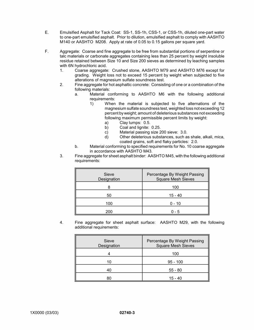
1X0000 (03/03) 02740-3
E. Emulsified Asphalt for Tack Coat: SS-1, SS-1h, CSS-1, or CSS-1h, diluted one-part waterto one-part emulsified asphalt. Prior to dilution, emulsified asphalt to comply with AASHTOM140 or AASHTO M208. Apply at rate of 0.05 to 0.15 gallons per square yard.
F. Aggregate: Coarse and fine aggregate to be free from substantial portions of serpentine ortalc materials or carbonate aggregates containing less than 25 percent by weight insolubleresidue retained between Size 10 and Size 200 sieves as determined by leaching sampleswith 6N hydrochloric acid.1. Coarse aggregate: Crushed stone, AASHTO M79 and AASHTO M76 except for
grading. Weight loss not to exceed 15 percent by weight when subjected to fivealterations of magnesium sulfate soundness test.
2. Fine aggregate for hot asphaltic concrete: Consisting of one or a combination of thefollowing materials:a. Material conforming to AASHTO M6 with the following additional
requirements:1) When the material is subjected to five alternations of the
magnesium sulfate soundness test, weighted loss not exceeding 12percent by weight; amount of deleterious substances not exceedingfollowing maximum permissible percent limits by weight:a) Clay lumps: 0.5.b) Coal and lignite: 0.25.c) Material passing size 200 sieve: 3.0.d) Other deleterious substances, such as shale, alkali, mica,
coated grains, soft and flaky particles: 2.0.b. Material conforming to specified requirements for No. 10 coarse aggregate
in accordance with AASHTO M43.3. Fine aggregate for sheet asphalt binder: AASHTO M45, with the following additional
requirements:
SieveDesignation
Percentage By Weight PassingSquare Mesh Sieves
8 100
50 15 - 40
100 0 - 10
200 0 - 5
4. Fine aggregate for sheet asphalt surface: AASHTO M29, with the followingadditional requirements:
SieveDesignation
Percentage By Weight PassingSquare Mesh Sieves
4 100
10 95 - 100
40 55 - 80
80 15 - 40
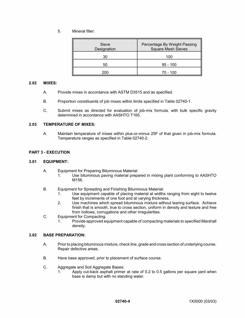
02740-4 1X0000 (03/03)
5. Mineral filler:
SieveDesignation
Percentage By Weight PassingSquare Mesh Sieves
30 100
50 95 - 100
200 70 - 100
2.02 MIXES:
A. Provide mixes in accordance with ASTM D3515 and as specified.
B. Proportion constituents of job mixes within limits specified in Table 02740-1.
C. Submit mixes as directed for evaluation of job-mix formula, with bulk specific gravitydetermined in accordance with AASHTO T165.
2.03 TEMPERATURE OF MIXES:
A. Maintain temperature of mixes within plus-or-minus 25F of that given in job-mix formula.Temperature ranges as specified in Table 02740-2.
PART 3 - EXECUTION
3.01 EQUIPMENT:
A. Equipment for Preparing Bituminous Material:1. Use bituminous paving material prepared in mixing plant conforming to AASHTO
M156.
B. Equipment for Spreading and Finishing Bituminous Material:1. Use equipment capable of placing material at widths ranging from eight to twelve
feet by increments of one foot and at varying thickness.2. Use machines which spread bituminous mixture without tearing surface. Achieve
finish that is smooth, true to cross section, uniform in density and texture and freefrom hollows, corrugations and other irregularities.
C. Equipment for Compacting:1. Provide approved equipment capable of compacting materials to specified Marshall
density.
3.02 BASE PREPARATION:
A. Prior to placing bituminous mixture, check line, grade and cross section of underlying course.Repair defective areas.
B. Have base approved, prior to placement of surface course.
C. Aggregate and Soil Aggregate Bases:1. Apply cut-back asphalt primer at rate of 0.2 to 0.5 gallons per square yard when
base is damp but with no standing water.
1X0000 (03/03) 02740-5
2. Allow 24 hours for base to entirely absorb primer. Blot excess primer with justenough sand to prevent pickup under traffic. Sweep loose sand from base beforeplacing base course.
D. Portland Cement Concrete, Bituminous and Brick Pavement Bases:1. Apply tack coat using equipment designed for that purpose.2. Apply tack coat uniformly to clean dry base at rate of 0.05 to 0.15 gallons per square
yard.3. Ensure that surface has cured and is satisfactorily tacky before placing mix.
E. Immediately prior to placing mix, apply thin coat of hot asphalt cement to contact surfacesof curbs, gutters, manholes and similar structures.
3.03 PLACING MIX:
A. Place base course mixture in one or more lifts with asphalt paver or spreader to providenominal compacted thickness as shown. Place surface course mixture with asphalt paverto provide nominal compacted thickness as shown. Minimum lift thickness at least two timesmaximum particle size. Maximum lift thickness to be that which can be demonstrated to belaid in a single lift and compacted to required uniform density and smoothness. Placematerial in continuous operation. Correct irregularities before final compaction of mixture.
B. If equipment being used produces tracks, pulling, indented areas or other permanentblemishes in material being spread, remove such equipment from site and substitute otherapproved spreading and finishing equipment.
C. Do not permit direction of movement of paving equipment to be changed by turning on newlycompleted base, binder or surface courses.
D. Adjacent to headers, gutters, manholes and similar structures, place surface course so thatfinished surface is 1/4-inch above edge of structure.
E. When the Engineer considers it impractical to place mix with two machines, one machine willbe permitted. Treat joints created by such operation as cold joints.
F. Rake joints to eliminate seams between lane passes.
3.04 COMPACTION:
A. Compact immediately after placing. Initial rolling with steel-wheel tandem roller, steel three-wheel roller, vibratory roller, or pneumatic-tire roller following paver as closely as possible,oriented with drive wheel closest to paver. If intermediate rolling is needed, use pneumatic-tire roller immediately behind initial rolling. Final rolling to eliminate marks from previousrolling. Use vibrating plate compactor or hand tamper to achieve thorough compaction inareas too small for roller. Keep steel wheel rollers wet while rolling.
3.05 COLD JOINTS:
A. Longitudinal: Apply tack coat to cold material before joining new work.
B. Transverse: Place bulkhead full depth of course or cut back minimum of three inches fromsloping surface with masonry saw. Apply tack coat to cold material.
3.06 BULKHEADS:
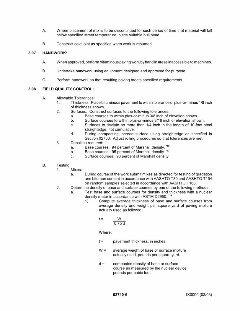
02740-6 1X0000 (03/03)
A. Where placement of mix is to be discontinued for such period of time that material will fallbelow specified street temperature, place suitable bulkhead.
B. Construct cold joint as specified when work is resumed.
3.07 HANDWORK:
A. When approved, perform bituminous paving work by hand in areas inaccessible to machines.
B. Undertake handwork using equipment designed and approved for purpose.
C. Perform handwork so that resulting paving meets specified requirements.
3.08 FIELD QUALITY CONTROL:
A. Allowable Tolerances:1. Thickness: Place bituminous pavement to within tolerance of plus-or-minus 1/8 inch
of thickness shown.2. Surfaces: Construct surfaces to the following tolerances:
a. Base courses to within plus-or-minus 3/8 inch of elevation shown.b. Surface courses to within plus-or-minus 3/16 inch of elevation shown.c. Surfaces to deviate no more than 1/4 inch in the length of 10-foot steel
straightedge, not cumulative.d. During compacting, screed surface using straightedge as specified in
Section 02750. Adjust rolling procedures so that tolerances are met.3. Densities required:
a. Base courses: 94 percent of Marshall density. *12
b. Base courses: 95 percent of Marshall density. *13
c. Surface courses: 96 percent of Marshall density.
B. Testing:1. Mixes:
a. During course of the work submit mixes as directed for testing of gradationand bitumen content in accordance with AASHTO T30 and AASHTO T164on random samples selected in accordance with AASHTO T168.
2. Determine density of base and surface courses by one of the following methods:a. Test base and surface courses for density and thickness with a nuclear
density meter in accordance with ASTM D2950. *14
1) Compute average thickness of base and surface courses fromaverage density and weight per square yard of paving mixtureactually used as follows:
t = W 0.75 d
Where:
t = pavement thickness, in inches.
W = average weight of base or surface mixtureactually used, pounds per square yard.
d = compacted density of base or surfacecourse as measured by the nuclear device,pounds per cubic foot.
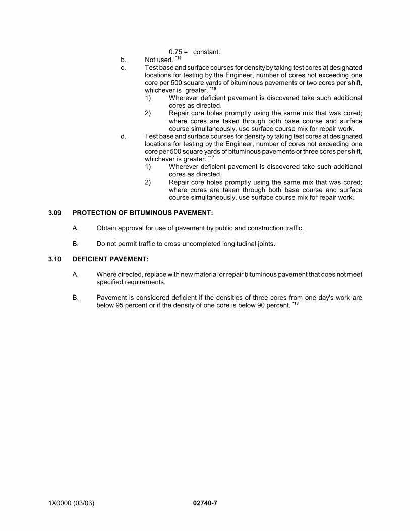
1X0000 (03/03) 02740-7
0.75 = constant.b. Not used. *15
c. Test base and surface courses for density by taking test cores at designatedlocations for testing by the Engineer, number of cores not exceeding onecore per 500 square yards of bituminous pavements or two cores per shift,whichever is greater. *16
1) Wherever deficient pavement is discovered take such additionalcores as directed.
2) Repair core holes promptly using the same mix that was cored;where cores are taken through both base course and surfacecourse simultaneously, use surface course mix for repair work.
d. Test base and surface courses for density by taking test cores at designatedlocations for testing by the Engineer, number of cores not exceeding onecore per 500 square yards of bituminous pavements or three cores per shift,whichever is greater. *17
1) Wherever deficient pavement is discovered take such additionalcores as directed.
2) Repair core holes promptly using the same mix that was cored;where cores are taken through both base course and surfacecourse simultaneously, use surface course mix for repair work.
3.09 PROTECTION OF BITUMINOUS PAVEMENT:
A. Obtain approval for use of pavement by public and construction traffic.
B. Do not permit traffic to cross uncompleted longitudinal joints.
3.10 DEFICIENT PAVEMENT:
A. Where directed, replace with new material or repair bituminous pavement that does not meetspecified requirements.
B. Pavement is considered deficient if the densities of three cores from one day's work arebelow 95 percent or if the density of one core is below 90 percent. *18
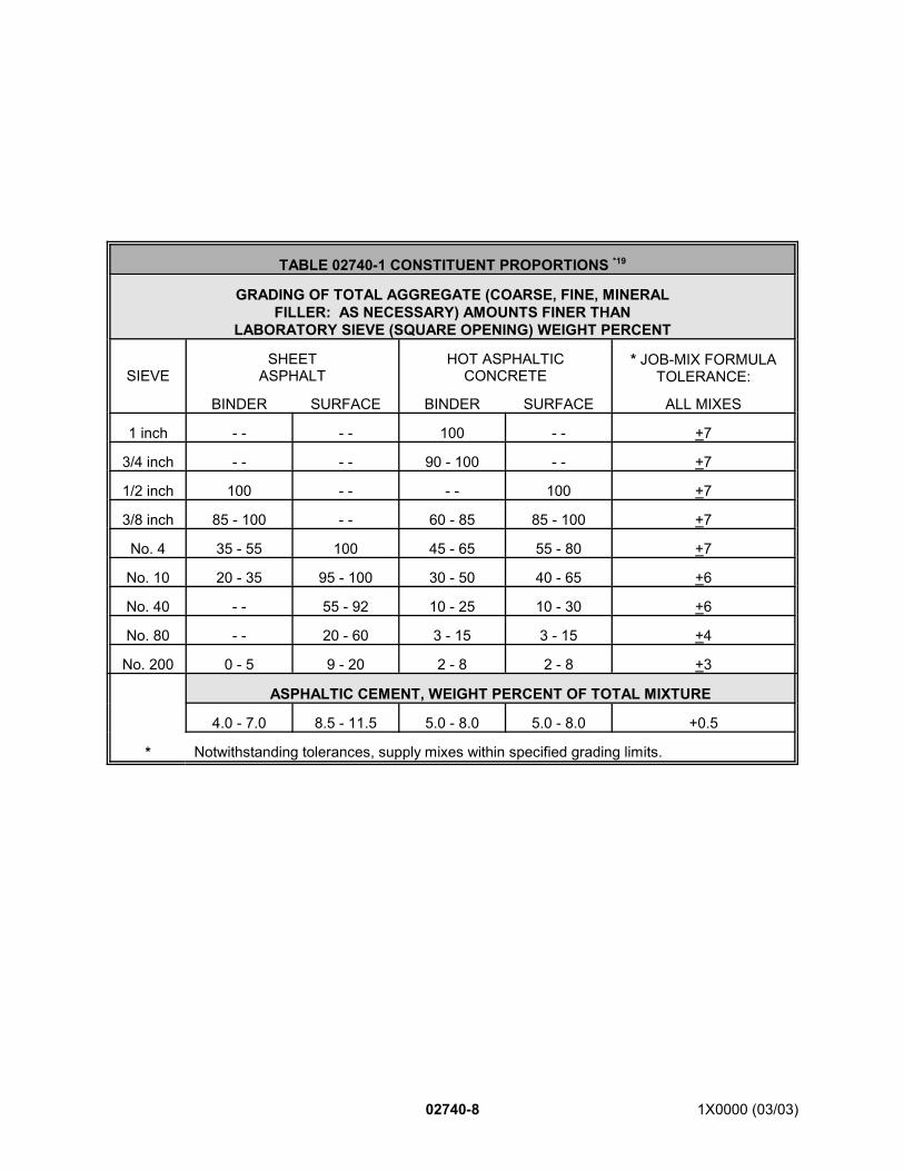
02740-8 1X0000 (03/03)
TABLE 02740-1 CONSTITUENT PROPORTIONS *19
GRADING OF TOTAL AGGREGATE (COARSE, FINE, MINERALFILLER: AS NECESSARY) AMOUNTS FINER THAN
LABORATORY SIEVE (SQUARE OPENING) WEIGHT PERCENT
SIEVESHEET
ASPHALTHOT ASPHALTIC
CONCRETE* JOB-MIX FORMULA
TOLERANCE:
BINDER SURFACE BINDER SURFACE ALL MIXES
1 inch - - - - 100 - - +7
3/4 inch - - - - 90 - 100 - - +7
1/2 inch 100 - - - - 100 +7
3/8 inch 85 - 100 - - 60 - 85 85 - 100 +7
No. 4 35 - 55 100 45 - 65 55 - 80 +7
No. 10 20 - 35 95 - 100 30 - 50 40 - 65 +6
No. 40 - - 55 - 92 10 - 25 10 - 30 +6
No. 80 - - 20 - 60 3 - 15 3 - 15 +4
No. 200 0 - 5 9 - 20 2 - 8 2 - 8 +3
ASPHALTIC CEMENT, WEIGHT PERCENT OF TOTAL MIXTURE
4.0 - 7.0 8.5 - 11.5 5.0 - 8.0 5.0 - 8.0 +0.5
* Notwithstanding tolerances, supply mixes within specified grading limits.
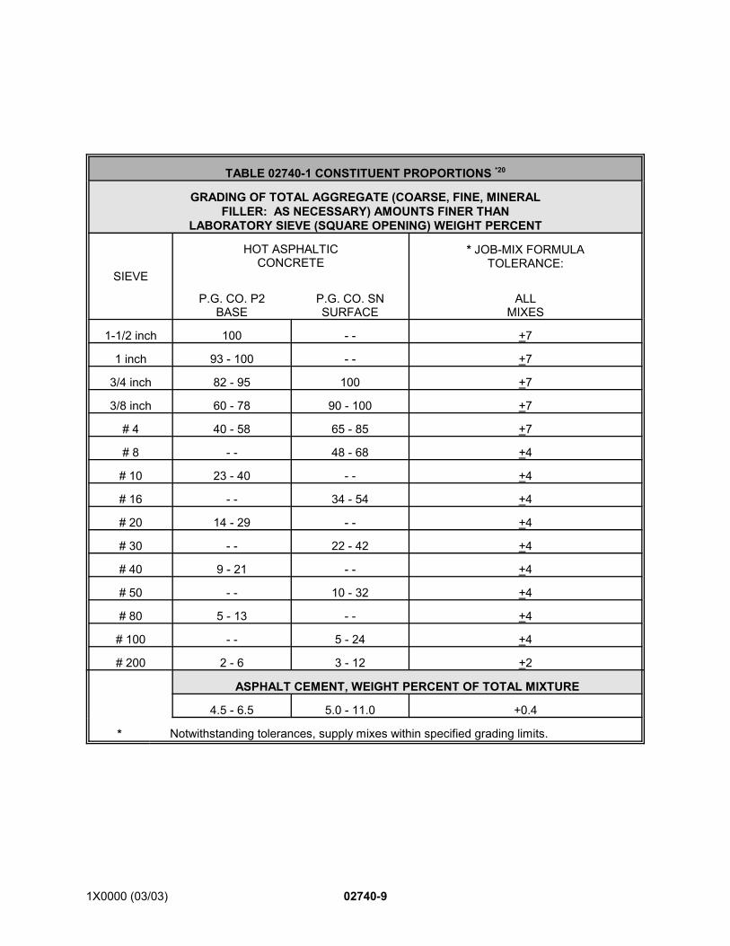
1X0000 (03/03) 02740-9
TABLE 02740-1 CONSTITUENT PROPORTIONS *20
GRADING OF TOTAL AGGREGATE (COARSE, FINE, MINERALFILLER: AS NECESSARY) AMOUNTS FINER THAN
LABORATORY SIEVE (SQUARE OPENING) WEIGHT PERCENT
SIEVE
HOT ASPHALTICCONCRETE
* JOB-MIX FORMULATOLERANCE:
P.G. CO. P2BASE
P.G. CO. SNSURFACE
ALLMIXES
1-1/2 inch 100 - - +7
1 inch 93 - 100 - - +7
3/4 inch 82 - 95 100 +7
3/8 inch 60 - 78 90 - 100 +7
# 4 40 - 58 65 - 85 +7
# 8 - - 48 - 68 +4
# 10 23 - 40 - - +4
# 16 - - 34 - 54 +4
# 20 14 - 29 - - +4
# 30 - - 22 - 42 +4
# 40 9 - 21 - - +4
# 50 - - 10 - 32 +4
# 80 5 - 13 - - +4
# 100 - - 5 - 24 +4
# 200 2 - 6 3 - 12 +2
ASPHALT CEMENT, WEIGHT PERCENT OF TOTAL MIXTURE
4.5 - 6.5 5.0 - 11.0 +0.4
* Notwithstanding tolerances, supply mixes within specified grading limits.
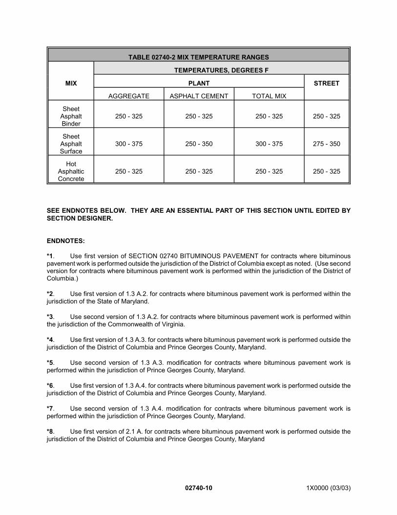
02740-10 1X0000 (03/03)
*1. Use first version of SECTION 02740 BITUMINOUS PAVEMENT for contracts where bituminouspavement work is performed outside the jurisdiction of the District of Columbia except as noted. (Use secondversion for contracts where bituminous pavement work is performed within the jurisdiction of the District ofColumbia.)
*2. Use first version of 1.3 A.2. for contracts where bituminous pavement work is performed within thejurisdiction of the State of Maryland.
*3. Use second version of 1.3 A.2. for contracts where bituminous pavement work is performed withinthe jurisdiction of the Commonwealth of Virginia.
*4. Use first version of 1.3 A.3. for contracts where bituminous pavement work is performed outside thejurisdiction of the District of Columbia and Prince Georges County, Maryland.
*5. Use second version of 1.3 A.3. modification for contracts where bituminous pavement work isperformed within the jurisdiction of Prince Georges County, Maryland.
*6. Use first version of 1.3 A.4. for contracts where bituminous pavement work is performed outside thejurisdiction of the District of Columbia and Prince Georges County, Maryland.
*7. Use second version of 1.3 A.4. modification for contracts where bituminous pavement work isperformed within the jurisdiction of Prince Georges County, Maryland.
*8. Use first version of 2.1 A. for contracts where bituminous pavement work is performed outside thejurisdiction of the District of Columbia and Prince Georges County, Maryland
TABLE 02740-2 MIX TEMPERATURE RANGES
TEMPERATURES, DEGREES F
MIX PLANT STREET
AGGREGATE ASPHALT CEMENT TOTAL MIX
SheetAsphaltBinder
250 - 325 250 - 325 250 - 325 250 - 325
SheetAsphaltSurface
300 - 375 250 - 350 300 - 375 275 - 350
HotAsphalticConcrete
250 - 325 250 - 325 250 - 325 250 - 325
SEE ENDNOTES BELOW. THEY ARE AN ESSENTIAL PART OF THIS SECTION UNTIL EDITED BYSECTION DESIGNER.
ENDNOTES:
1X0000 (03/03) 02740-11
*9. Use second version of 2.1 A. modification for contracts where bituminous pavement work isperformed within the jurisdiction of Prince Georges County, Maryland.
*10. Use first version of 2.1 B. for contracts where bituminous pavement work is performed outside thejurisdiction of the District of Columbia and Prince Georges County, Maryland.
*11. Use second version of 2.1 B. modification for contracts where bituminous pavement work isperformed within the jurisdiction of Prince Georges County, Maryland.
*12. Use first version of 3.8 A.3.a. for contracts where bituminous pavement work is performed outsidethe jurisdiction of the District of Columbia and Prince Georges County, Maryland.
*13. Use second version of 3.8 A.3.a. modification for contracts where bituminous pavement work isperformed within the jurisdiction of Prince Georges County, Maryland.
*14. Use first version of 3.8 B.2.a. including (1) for contracts where bituminous pavement work isperformed outside the jurisdiction of the District of Columbia and Prince Georges County, Maryland.
*15. Use second version of 3.8 B.2.a. modification for contracts where bituminous pavement work isperformed within the jurisdiction of Prince Georges County, Maryland.
*16. Use first version of 3.8 B.2.b. including (1)-(2) for contracts where bituminous pavement work isperformed outside the jurisdiction of the District of Columbia and Prince Georges County, Maryland.
*17. Use second version of 3.8 B.2.b. including (1)-(2) modification for contracts where bituminouspavement work is performed within the jurisdiction of Prince Georges County, Maryland.
*18. Add 3.10 B. for contracts where bituminous pavement work is performed within the jurisdiction ofPrince Georges County, Maryland.
*19. Use first version of TABLE 02740-1 for contracts where bituminous pavement work is performedoutside the jurisdiction of the District of Columbia and Prince Georges County, Maryland.
*20. Use second version of TABLE 02740-1 modification for contracts where bituminous pavement workis performed within the jurisdiction of Prince Georges County, Maryland.
END OF SECTION
1X0000 (03/03) 02740 - 1
SECTION 02740(Version 2)*1
BITUMINOUS PAVEMENT
PART 1 - GENERAL
1.01 DESCRIPTION:
A. This section specifies providing bituminous pavements complete in place as shown; placedon bases prepared under Section 02725, Base for Pavements and under Section 02750,Concrete Pavement.
B. Related Work Specified Elsewhere:1. Base for pavements: Section 02725.2. Concrete pavement: Section 02750.
C. Definitions:1. Equipment: This includes such specialized devices and tools as are customarily
used in the construction of bituminous pavements; e.g., lutes, rakes, irons.
1.02 SUBMITTALS:
A. Submit the following for approval in accordance with the General Requirements and with theadditional requirements as specified for each:1. Certification:
a. For each delivery of asphaltic material, submit certificate stating type andamount of asphalt and results of specified tests.
2. Documentation:a. Job-mix formula:
1) For each mix to be supplied submit job-mix formula based onexpected production averages.
2) In formula establish:a) Weight percent of total aggregate and of aggregate finer
than each required sieve size.b) Weight percent of total mix of asphalt cement.c) Temperature of mix when placed.
3) Maintain job-mix formula once approved.b. Weight ticket: For each load of bituminous mixture delivered to the site,
submit weight ticket showing the following:1) Mix type.2) Mix temperature.3) Identification of the truck.4) Tare weight of truck.5) Loaded weight of truck.6) Net weight of load.7) Time of leaving mix plant.8) Signature of the Engineer's plant representative.
1.03 QUALITY ASSURANCE:
A. Codes, Regulations, Reference Standards and Specifications:1. Comply with codes and regulations of the jurisdictional authorities.2. AASHTO: M6, M17, M20, M29, M43, M45, M76, M79, M81, M82, M140, T30, T164,
T165, T168.
02740 - 2 1X0000 (03/03)
3. ASTM: D3515.
B. Sources of Supply:1. Not less than 20 days prior to beginning the work, inform the Engineer of the source
of the materials to be used and obtain approval.2. Once approved, do not change source of supply.3. Do not construe approval as approval of entire location but as approval only insofar
as material continues to meet specified requirements.4. Maintain quality of material. Material may be sampled and tested by the Engineer
as often as the Engineer deems necessary.5. The Engineer has the right to reject material at the job site by visual inspection
pending sampling and testing.6. Provide mix for a given area as defined by the Engineer from one mixing plant.
1.04 PRODUCT DELIVERY, STORAGE AND HANDLING:
A. Delivery Trucks:1. For transporting bituminous, mixtures use trucks which show no leakage of oil or
grease, have solid metal dump-type beds which are clean and smooth with tightfitting rear gate to prevent loss of materials in transit.
2. Prior to loading, spray inside surface of truck beds with minimum amount ofapproved thin oil or mixture of lime and water proportioned 50 gallons of water to 100pounds of lime necessary to prevent adhesion of the mixture. Do not use kerosene,gasoline or excessive amount of oil.
3. Equip trucks with coverings to protect loads from weather and with suitable insulationto prevent undue heat loss during transit at temperatures below 40F.
B. Weighing of Bituminous Mixtures:1. Provide approved truck scales having both dial and automatic printer or use public
scales.2. Use scales complying with applicable laws, ordinances and regulations governing
use of scales.3. Have scales tested and sealed by authorized public official as often as directed to
ensure their accuracy, and within the six months prior for use for the work. TheEngineer has the option to require retesting and resealing.
4. At least once a week and whenever directed by the Engineer, check tare weight ofeach truck with full load of fuel and fitted with its normal equipment.
1.05 JOB CONDITIONS:
A. Environmental Requirements:1. Do not place bituminous pavement on wet surfaces.2. Place bituminous pavement only when temperature of air and base exceed 40F and
when by U.S. Weather Bureau forecast, the temperature is expected to remainabove 40F during the course of the work.
PART 2 - PRODUCTS
2.01 MATERIALS:
A. Asphalt Cement: AASHTO M20, Penetration Grade 85-100.
B. Cut-Back Asphalt for Prime Coat: AASHTO M82, Grade MC-30 or MC-70 as conditionswarrant.
1X0000 (03/03) 02740 - 3
C. Emulsified Asphalt for Tack Coat: As conditions warrant, use either of the following:1. AASHTO M81, Cut-Back Asphalt (Rapid-Curing Type), Grade RC-70.2. AASHTO M140, Emulsified Asphalt, Grade SS-1 or SS-1h, diluted with water in the
volumetric ratio of three parts emulsion to one part water.
D. Aggregate: Coarse and fine aggregate free from substantial portions of serpentine or talcmaterials or carbonate aggregates containing less than 25 percent by weight insolubleresidue retained between Size 10 and Size 200 sieves as determined by leaching sampleswith 6N hydrochloric acid.1. Coarse aggregate: Crushed stone, AASHTO M79 and AASHTO M76 except for
grading. Weight loss not to exceed 15 percent by weight when subjected to fivealterations of magnesium sulfate soundness test.
2. Fine aggregate for hot asphaltic concrete: Consisting of one or a combination of thefollowing materials:a. Material conforming to AASHTO M6 with the following additional
requirements:1) When the material is subjected to five alternations of the
magnesium sulfate soundness test, weighted loss not exceeding 12percent by weight; amount of deleterious substances not exceedingfollowing maximum permissible percent limits by weight:a) Clay lumps: 0.5.b) Coal and lignite: 0.25.c) Material passing size 200 sieve: 3.0.d) Other deleterious substances, such as shale, alkali, mica,
coated grains, soft and flaky particles: 2.0.b. Material conforming to specified requirements for No. 10 coarse aggregate
in accordance with AASHTO M43.3. Fine aggregate for sheet asphalt binder: AASHTO M45, with the following additional
requirements:
SieveDesignation
Percentage By Weight PassingSquare Mesh Sieves
8 100
50 15 - 40
100 0 - 10
200 0 - 5
THIS SPACE NOT USED.
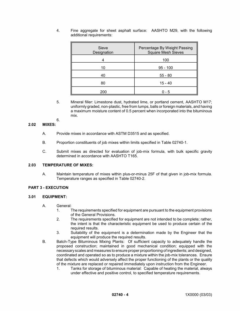
02740 - 4 1X0000 (03/03)
4. Fine aggregate for sheet asphalt surface: AASHTO M29, with the followingadditional requirements:
SieveDesignation
Percentage By Weight PassingSquare Mesh Sieves
4 100
10 95 - 100
40 55 - 80
80 15 - 40
200 0 - 5
5. Mineral filler: Limestone dust, hydrated lime, or portland cement, AASHTO M17;uniformly graded, non-plastic, free from lumps, balls or foreign materials, and havinga maximum moisture content of 0.5 percent when incorporated into the bituminousmix.
6.2.02 MIXES:
A. Provide mixes in accordance with ASTM D3515 and as specified.
B. Proportion constituents of job mixes within limits specified in Table 02740-1.
C. Submit mixes as directed for evaluation of job-mix formula, with bulk specific gravitydetermined in accordance with AASHTO T165.
2.03 TEMPERATURE OF MIXES:
A. Maintain temperature of mixes within plus-or-minus 25F of that given in job-mix formula.Temperature ranges as specified in Table 02740-2.
PART 3 - EXECUTION
3.01 EQUIPMENT:
A. General:1. The requirements specified for equipment are pursuant to the equipment provisions
of the General Provisions.2. The requirements specified for equipment are not intended to be complete; rather,
the intent is that the characteristic equipment be used to produce certain of therequired results.
3. Suitability of the equipment is a determination made by the Engineer that theequipment will produce the required results.
B. Batch-Type Bituminous Mixing Plants: Of sufficient capacity to adequately handle theproposed construction; maintained in good mechanical condition; equipped with thenecessary scales and measures to ensure proper proportioning of ingredients; and designed,coordinated and operated so as to produce a mixture within the job-mix tolerances. Ensurethat defects which would adversely affect the proper functioning of the plants or the qualityof the mixture are replaced or repaired immediately upon instruction from the Engineer.1. Tanks for storage of bituminous material: Capable of heating the material, always
under effective and positive control, to specified temperature requirements.
1X0000 (03/03) 02740 - 5
a. Heating: Accomplished by steam coils, electricity or other means so that noflame can come in contact with the heating tank, and so that uniform heatingof the entire contents is provided.
b. Circulating system for the bituminous material: Of adequate size to ensurethe proper and continuous circulation during the entire operating period.
c. Pipelines and fittings: Steam-jacketed or otherwise properly insulated toprevent heat loss.
d. Provide separate tanks and delivery lines for each grade of asphalt cementor liquid asphaltic material for mixtures to be produced in the same mixerunit.
2. Feeder for drier: Accurate mechanical means for uniformly feeding the aggregateinto the drier so that a uniform production and a uniform temperature may besecured. a. Have each aggregate, except for mineral filler added cold, fed to a central
elevator, conveyor or feeder by accurate mechanical means with adjustablegates that will deliver each aggregate in the desired proportion. When morethan one cold elevator is used, feed each by a separate feeder unit with theindividual controls integrated with a master total control.
b. Set and lock the total and proportional controls when so directed by theEngineer.
3. Driers: Capable of drying and heating the aggregates as specified for any item, andof sufficient capacity to supply the mixing unit at its operating capacity. Drier is tocontinuously agitate the aggregates during the heating and drying process so thatthe temperature can be positively regulated.
4. Screening system for grading the aggregate: Shaker or vibrating type capable ofscreening the aggregates to specified sizes and proportions, producing a quantityof aggregate sufficient to keep the mixer operating at the rated plant capacity.a. Have screening system equipped with a chute or pipe for removal of
oversized aggregate having the discharge end located so as not to createa hazard or nuisance.
b. Revolving double-jacketed screens may be accepted if they give satisfactoryperformance of a maximum plant production.
5. Storage bins: Of sufficient capacity to supply the mixer when it is operating at fullcapacity; divided into at least three compartments arranged to ensure separate andadequate storage of appropriate proportions of aggregates; each compartmentprovided with an adequate overflow opening located so as to prevent backing up ofmaterial into other bins.a. Each compartment provided with its individual outlet gate, so designed and
constructed that when closed there will be no leakage; gates cutting offquickly and completely.
b. Have discharge points of overflow located so that they will not create ahazard or nuisance.
c. Bins equipped with adequate tell-tale devices to indicate the position of theaggregate in the bins at the lower quarter points.
d. Provide separate dry storage for the mineral filler.6. Bituminous control unit: Satisfactory means, either by weighing, metering or
volumetric measurements, to obtain the proper amount of bituminous material in themix within the tolerance specified for the job-mix; with suitable means, either bysteam-jacketing or other insulation, for maintaining the specified temperature of thebituminous material in the pipelines, meters, weigh buckets, spray bars, and othercontainers or flow lines.
7. Bitumen bucket (if a bucket is used for weighing the bituminous material): Capacitysufficient to hold not less than 20 percent of the weight of aggregate required for onebatch; steam-jacketed or equipped with properly insulated electric heating units; andsuspended on dial scales or beam scales so that the tare weight of bucket will beshown for each weighing.
02740 - 6 1X0000 (03/03)
a. Bucket equipped with tell-tale device to accurately control the net weight ofbituminous material added to the mix to within two percent above or belowthe actual weight in pounds required.
b. Bucket arranged so that it will deliver molten bitumen in a thin uniform sheetor in multiple streams the full width of the mixer, except in the case of arotary mixer where bitumen is sprayed.
8. Thermometric equipment: Have plant equipped with the following as approved:a. Armored thermometer reading from 200F to 400F, fixed at a suitable
location so that the temperature of the bitumen at the bucket or spray barcan be determined.
b. Dial-scale, mercury-activated thermometer, electric pyrometer or otherapproved thermometric instrument, so placed at the discharge chute of thedrier as to register automatically or indicate the temperature of the heatedaggregate; of such accuracy that the temperature of the aggregate can bemaintained within the limits specified; and so located so that its dial is inplain view of the drier fireman or feeder.
9. Mixing time: Positive means to govern the time of mixing and to maintain it constantunless changed by order of the Engineer.
10. Timing devices: Accurate timelock to control the operation of a complete mixingcycle by locking the weight box gate after the charging of the mixer, until the closingof the mixer gate at the completion of the cycle. Timeclock is to lock the bitumenbucket throughout the dry-mixing period and lock the mixer gate throughout the dry-mixing and wet-mixing periods.a. Control of the timing is to be flexible and capable of being set at intervals of
not more than five seconds throughout cycles up to three minutes.b. A mechanical batch or box counter is to designed so as to register only
upon the actuation of the bucket release and to preclude the register of drybatches or the register of material through the operation of pulling bins.
11. Plant scales: Either the beam or springless-dial type; of a standard make designedas an integral part of the plant; accurate to within one-half percent of the true weightof the load being weighed; having significant graduations that can be easily read tothat degree of accuracy; and with dials and indicators in plain view of the operatorwhen on the weighing platform.a. Beam-type scales: Balanced on knife edges and fulcrums that are kept
clean and constructed so that they will not easily be thrown out of alignmentand adjustment; each beam having a locking device which will permit thebeam either to be suspended or thrown into action; a separate beam foreach size aggregate and a tare beam for balancing the hopper; eachaggregate beam equipped with an auxiliary dial or tell-tale that will indicatethat the required load to the weighing hopper is being approached and willcontinue to indicate further movement of the beam after that.1) For weighing bituminous material, use beam-type scales that are
provided with a tare beam and a full-capacity beam.2) Gradations: Two pounds or smaller.
b. Dial scales: Springless and so constructed, installed, and maintained, to befree from vibration; of such size that the numerals on the dial can be easilyread from a distance of 25 feet; dials of the compounding type having fullcomplements of index pointers.1) For weighing asphalt cement, capacity equal to or less than two
times the maximum weight of the material to be weighed.2) Graduations: Such that they can be easily read to the nearest two
pounds.c. Weigh box or hopper: Provide means for accurately weighing each bin size
of aggregate in a weigh box or hopper suspended on scales and of sufficientsize to hold a full batch without hand raking or running over; with gates onboth bins and hopper constructed so as to prevent leakage when they are
1X0000 (03/03) 02740 - 7
closed. Have container supported on knife edges or fulcrums constructedso that it will not easily be thrown out of alignment or adjustment; withedges, ends and sides free from contact with supporting parts that couldpossibly affect proper weighing; and with adequate clearance of the partsto prevent accumulation of foreign materials. In plants where the weigh boxis enclosed for the purpose of minimizing dust nuisance, have someprovision made to permit sampling the materials by the Engineer asdischarge is made from the storage bins.
d. Provide ten 50-pound standard test weights at each plant for testingweighing equipment.
12. Mixer unit: Batch mixer of an approved twin-pugmill type or rotary-drum type, witha batch capacity of not less than 2,000 pounds, and capable of producing a uniformmixture within the job-mix tolerances specified; constructed as to prevent leakageof contents until the batch is to be discharged.a. If mixer is the pugmill type, have the clearance of the blades from fixed and
moving parts not to exceed 3/4 inch, unless the maximum aggregateparticle exceeds 1-1/2 inches.
b. If not enclosed, equip the mixer box with a dust hood to prevent loss of dust.When so enclosed, make provision to permit visual inspection of mixingoperation by the Engineer.
13. Dust collectors: When plant is located where dust may be objectionable or becomea nuisance or where dust interferes with the efficiency of the operation of the plant,provide proper housing, mixing covers, or dust collecting systems. Make provisionto dispose of the material so collected or to return it uniformly to the mixture, as theEngineer may direct.
14. Safety Requirements:a. Provide a mixer platform sufficiently rigid and of ample size to provide for
safe and convenient access to the mixer and pertinent equipment.b. Place adequate and safe stairways to the mixer platform and guarded
ladders to other plant units at points where accessibility is necessary duringplant operations.
c. Thoroughly guard gears, pulleys, chains, sprockets and other dangerousmoving parts.
d. Always maintain a clear, ample and unobstructed passage in and aroundthe truck loading space. Keep this space free from drippings from themixing platform.
C. Continuous-Type Bituminous Mixing Plants: Meet the requirements for batch-typebituminous mixing plants, except for the requirements as to scales and weighing equipmentand the requirements for the mixer unit which do not apply. The following are required incontinuous mixing plant:1. Gradation control unit: Means for accurately proportioning aggregate from each bin
either by weighing or by volumetric measurement. When gradation control is byvolume, have the unit include a feeder mounted under the bin compartments. Equipeach bin with an accurately controlled individual gate to form an orifice forvolumetrically measuring the material drawn from each bin compartment. Make theorifice of adequate dimensions to provide a positive feed without bridging and withone dimension adjustable by positive mechanical means provided with a lock.Provide indicators graduated from sufficient subdivisions of inches to provideaccuracy of measurements, on each gate to show the size of gate opening. Ifmineral filler is required, proportion it separately, and add it to the mix in such amanner as to ensure uniform distribution.
2. Weight Calibration of Aggregate Feed: Have plant include a means for calibrationof gate openings with weight test samples. Allow materials fed out of the binsthrough individual orifices to be bypassed to a suitable test box or boxes, thematerial from each compartment being confined separately. Equip the plant to
02740 - 8 1X0000 (03/03)
handle conveniently test samples of size adequate to provide an accurate gatecalibration commensurate with the aggregate size, the gate opening, and the plantcapacity setup. Provide an accurate platform scale with a minimum capacity of 500pounds.
3. Synchronization of Aggregate Feed and Bitumen Feed: Provide satisfactory meansto afford positive interlocking control between the flow of aggregate from the binsand the flow of bituminous material from the meter or other proportioning source.Accomplish this control by interlocking mechanical means or by another positivemethod under the control of the Engineer.
4. Mixer Unit for Continuous Method: Continuous mixer of an approved twin-pugmilltype, steam-jacketed and capable of producing a uniform mixture within the job-mixtolerances. Use paddles that are adjustable for angular position on the shafts andreversible to retard the flow of the mix. Have the mixer carry a manufacturer's platestating the net volumetric contents of the mixer at the several heights inscribed ona permanent gauge. Provide charts showing the rate of feed of aggregate perminute required, controlled by weight method under the following formula. Theweights will be determined by tests made by the Engineer.
Mixing time in seconds = Pugmill dead capacity in lbs.Pugmill output in lbs./sec.
D. Trucks for Transporting Bituminous Mixtures: Solid metal, dump-type bed, clean andsmooth; with a tight-fitting rear gate to prevent loss of materials while in transit.1. Spray the inside surface of the bed with a minimum amount of approved thin oil or
a mixture of lime and water proportioned at a rate of 100 pounds of lime to 50gallons of water, prior to loading, to prevent adhesion of the mixture to the bed.Kerosene and gasoline will not be approved nor will the use of excessive quantitiesof approved oil be permitted.
2. Equip each truck with a canvas or other covering of sufficient size to cover thematerial and protect it from weather. To prevent excessive temperature loss whilein transit, equip the trucks with insulating units composed of wood or other approvedmaterial between October 15 and March 15, when so directed by the Engineer.
3. Do not use trucks with appreciable oil leakage that may cause damage to the newbituminous construction.
E. Bituminous Spreading and Finishing Machines: Use spreading and finishing machine thatoperates without side forms and of a self-propelled type approved by the Engineer andequipped with the following features:1. An efficient steering device of both forward and reverse traveling speeds.2. Adjustments, of the manufacturer's standard design, that permit the bituminous
material to be placed to a maximum width of not less than 12 feet and to a minimumwidth of 8 feet; the adjustments made in increments of one foot or less.
3. Devices to adjust the thickness of material being placed, with suitable hopper forreceiving the material, and with distributing screws, rake bars, or similar for evenlyplacing the mixture in front of the screed.
4. The screed is a strike-off device operated by cutting, crowding or other practicableaction that is effective on the bituminous mixture being placed, that is equipped witha heater, that produces a finished surface of uniform texture, and that is adjustableto the shape of the cross section of the finished surface.
5. Joint-leveling or joint-blending devices for smoothing and adjusting longitudinal jointsbetween adjacent layers of the same thickness.
6. Ability to spread the bituminous mixture without tearing the surface and to strike afinish that is smooth, true to cross section, uniform in density and texture, and freefrom hollows, corrugations and other irregularities.
F. Tools for Finishing Asphalt Surfaces:
1X0000 (03/03) 02740 - 9
1. Asphalt lute: Wood, with a blade six feet in length, six inches in width, and one-halfinch in thickness; edged on the contact surface; with the handle 16 feet in length, toone end of which the blade is firmly affixed with adequate bracing.
2. Rakes: Metal, not be less than 14 inches wide; with tines of sufficient depth topenetrate and rake the material for its full depth.
3. Smoothing irons: Metal, weighing not less than 40 pounds; with bearing surface notbe less than 80 square inches.
4. Hand tampers for compaction of bituminous material in locations inaccessible torollers: Metal, weighing not less than 25 pounds, with tamping face of not less than48 square inches.
G. Rollers: Use rollers that are in first-class mechanical condition, complying with therequirements for the individual items as to classifications, weights and service requirements.Use tandem and three-wheel rollers that are power-driven, always capable of being reversedsmoothly, and free from backlash, loose-link motion, faulty steering mechanism, and wornking bolts and bearings. A roller of these types that has been improperly weighted or that hasin any way been thrown out of its original balance by the application of attachments notapproved or not the manufacturer's original standard design will not be permitted on theproject; nor will any roller that does not have displayed thereon in permanent legiblecharacters the manufacturer's guaranteed net operating weight as distributed on each axlebe permitted on the project. The net operating weight is the actual net weight plus one-halfof the total maximum weight of fuel and water. Ensure that rolls have closely fitting springscrapers, adjustable for forward and reverse motion.1. Two-Axle Tandem Rollers: Of rigid construction with the following features:
a. Having a low center of gravity and balanced on the longitudinal axis, smoothoperating friction clutches of the reversing type, smooth operating brakes,both hand-operated and power-operated steering devices.
b. The type of driving mechanism is to be such as to give the lowest sideclearance possible.
c. Equipped with a water sprinkling system having a tank capacity as indicatedin the table below, with the water piped to the spray pipes on each roll, thespray pipe extending the full width of the roll and installed so as to be readilycleanable, the water distributed from the spray pipes through cocoa-fibermats securely suspended against the rolling surface, and having separatevalves to control the flow of water to each roll and if enough pressure is notsecured by force of gravity, some satisfactory pressure device installed.
d. Minimum compression per inch of width of drive roll may include only the netoperating weight of the roller, with the distribution of weight such that notmore than 68 percent of the total gross weight is placed upon the drive roll.
THIS SPACE NOT USED
02740 - 10 1X0000 (03/03)
Manufacturer'srating,
tons5 - 6 10 - 12 15
Minimum diameter,drive roll,
inches42 60 70
Minimum diameter,guide roll,
inches36 48 50
Minimum rollingwidth,inches
20 20 20
Minimum compression,per inch width of drive roll,
pounds130 220 300
Minimum water sprinklingtank capacity, gallons 70 100 125
2. Three-Axle Tandem Rollers: Of rigid construction with the following features:a. Having a low center of gravity and balanced on the longitudinal axis, smooth
operating friction clutches of the reversing type, smooth operating brakes ofample capacity, and power-operated steering devices, with both guide rollssteerable and the ratio of steering synchronized.
b. The type of driving mechanism is to be such as to give the lowest sideclearance possible.
c. Equipped with a water sprinkling system having a tank capacity as indicatedin the table below, with the water piped to the spray pipes on each roll, thespray pipe extending the full width of the roll and installed so as to be readilycleanable, the water distributed from the spray pipes through cocoa-fibermats securely suspended against the rolling surface, and having separatevalves to control the flow of water to each roll and if enough pressure is notsecured by force of gravity, some satisfactory pressure device installed.
d. Minimum compression per inch of width of drive roll may include only the netoperating weight of the roller, with the distribution of weight such that notmore than 68 percent of the total gross weight is placed upon the drive roll.
THIS SPACE NOT USED
1X0000 (03/03) 02740 - 11
Manufacturer'srating,
tons12 - 20
Minimum diameter,drive roll,
inches60
Minimum diameter,guide roll,
inches48
Minimum rollingwidth,inches
54
Minimum compression, per inch width ofdrive roll, pounds,
all three rollers in same plane210
Minimum water sprinklingtank capacity,
gallons200
3. Pneumatic-Tire Rollers: Provide the following features:a. Multiple-axle, multiple-wheel type with smooth-tread pneumatic tires of equal
size staggered on the axles at such spacing and overlaps as will provideuniform compactive pressure for the full compacting width of the roller whenoperating. In operating pneumatic-tire rollers, have the tires inflated to thesame air pressure, within a tolerance of five pounds, and to the pressurerequired or designated for use.
b. If provided, have oscillation of the wheels in a vertical plane only.c. Capable of being ballasted sufficiently to bring its loaded weight to at least
2-1/2 times its own weight and of exerting compactive ground contactpressures of at least 80 psi. Have the roller ballasted to the extent requiredor designated; and within limits prescribed above, so that the roller providesthe compactive ground pressure per square inch that is most efficient underthe conditions and for the purpose of its use, and as directed.
d. Furnish to the Engineer charts or tabulations showing the contact areas andcontact pressures for the full range of tire inflation pressures and for the fullrange of tire loadings for each type and size compactor tire furnished.
4. Trench Rollers: Provide the following features:a. Constructed so that the guide roll or wheel either operates in tandem with
the compression roll on the area to be compacted or in tandem with theauxiliary wheel or roll.
b. An auxiliary wheel or roll that operates outside the area to be compacted,mounted upon an axle having height adjustability so that the contact surfaceof the auxiliary wheel or roll is capable of being adjusted at least 10 inchesabove and two inches below the rolling plane of the compression roll or theamount necessary to compact the soils base to the plan elevation. If theguide roll or wheel operates in tandem with the auxiliary roll or wheel, it mayor may not be adjustable as to height. Have the auxiliary wheel or rolloperate upon the surface of the pavement adjacent to the area to becompacted, and at such a distance from the pavement edge as to cause nochange thereto. Keep the auxiliary wheel or roll in such adjustment as to
02740 - 12 1X0000 (03/03)
height that the compression roll will develop a smooth compacted surfacetrue to crown.
c. Smooth operating friction clutches of the reversing type, smooth operatingbrake of ample capacity, and either hand-operated or power-operatedsteering devices.
d. Compression roll may be of hollow-type construction and the minimumweight secured by liquid ballast; minimum 300 pounds compression per inchof width of compression roll; and minimum width of compaction at least 15inches.
e. Maximum rolling speed 1-1/2 miles per hour.f. Equipped with sprinkling system having a tank or tanks with total capacity
of not less than 50 gallons, with the water piped to the spray pipes on eachroll, the spray pipes extending the full width of rolls and installed so as to bereadily cleanable, the water distributed from the spray pipes through cocoa-fiber mats securely suspended against the rims of the rolls, and havingseparate to control the flow of water to each roll and if enough pressure isnot secured by force of gravity, some satisfactory pressure device installed.
3.02 BASE PREPARATION:
A. Prior to placing bituminous mixture, check line, grade and cross section of underlying course.Repair defective areas.
B. Have base approved, before beginning installation work.
C. Aggregate and Soil Aggregate Bases:1. Apply primer using equipment designed for that purpose.2. When base is dry, uniformly apply primer at rate of application directed,
approximately 0.15 gallons per square yard.3. Allow primer to cure satisfactorily before placing mix.
D. Portland Cement Concrete, Bituminous and Brick Pavement Bases:1. Apply tack coat using equipment designed for that purpose.2. Prior applying tack coat, satisfactorily clean the base and verify that base is dry at
time of application.3. Apply tack coat uniformly to clean dry base at rate as directed by the Engineer, 0.02
to 0.05 gallons per square yard.4. The Engineer has the right to direct omission of tack coat over new bituminous
courses, or to order the tack coat to be "run in" by the use of trucks or other rubber-tire equipment.
5. Ensure that surface has cured and is satisfactorily tacky before placing mix.
E. Immediately prior to placing mix, apply thin coat of hot asphalt cement to contact surfacesof curbs, gutters, manholes and similar structures.
3.03 PLACING MIX:
A. Place mix by two or more machines operating in echelon in such manner that joints betweenlanes are hot. Keep machines clean and free from accumulations of asphaltic materials byacceptable means.
B. If equipment being used produces tracks, pulling, indented areas or other permanentblemishes in material being spread, remove such equipment from site and substitute otherapproved spreading and finishing equipment.
1X0000 (03/03) 02740 - 13
C. Do not permit direction of movement of paving equipment to be changed by turning on newlycompleted base, binder or surface courses.
D. Adjacent to headers, gutters, manholes and similar structures, place surface course so thatfinished surface is 1/4-inch above edge of structure.
E. When the Engineer considers it impractical to place mix with two machines, one machine willbe permitted. Treat joints created by such operation as cold joints.
3.04 COMPACTION:
A. Compact as soon as the condition of the mix permits. Have rollers start longitudinally at theextreme sides and proceed toward the center of pavement, overlapping on each successivetrip by one-half the width of the rear roll. Diagonally roll surface courses in two directions, thesecond diagonal crossing the lines of the first. Have rolling proceed in one continuousoperation until roller marks are eliminated and until courses required density, specified belowunder Tolerances.
B. Perform breakdown rolling with a three-wheel steel-wheel roller designed for the purpose; theweight as required for job conditions.
C. Perform initial finish rolling and final rolling with at least one 10-ton tandem steel-wheel rollerand one three-axle tandem steel-wheel roller designed for the purpose.
D. When temperature is below 50F, the Engineer may direct the use of a 5-ton tandem roller toseal the surface.
E. Perform intermediate rolling of sheet asphalt with tandem steel-wheel rollers or with self-propelled pneumatic-tire rollers designed for the purpose, as conditions warrant.
F. Perform intermediate rolling of hot asphaltic concrete with self-propelled pneumatic-tirerollers designed for the purpose.
G. For binder courses adjacent to structures where use of rollers is impractical, use handtampers designed for the purpose.
H. Use trench rollers designed for the purpose where necessary.
3.05 COLD JOINTS:
A. Avoid cold joints; permitted only when necessary in the opinion of the Engineer.
B. Where mix is to be placed against cold asphaltic material, cut back the cold asphalticmaterial with a power masonry saw a minimum of three inches so that a vertical face ofcompacted full-thickness material is exposed. Treat this cut face as a contact surface.
3.06 BULKHEADS:
A. Where placement of mix is to be discontinued for such period of time that material will fallbelow specified street temperature, place suitable bulkhead.
B. Construct cold joint as specified when work is resumed.
3.07 HANDWORK:
02740 - 14 1X0000 (03/03)
A. When approved, perform bituminous paving work by hand in areas inaccessible to machines.
B. Undertake handwork using equipment designed and approved for purpose.
C. Perform handwork so that resulting paving meets specified requirements.
3.08 FIELD QUALITY CONTROL:
A. Allowable Tolerances:1. Thickness: Place bituminous pavement to within tolerance of plus-or-minus 1/8 inch
of thickness shown.2. Surfaces: Construct surfaces to the following tolerances:
a. Binder courses to within plus-or-minus 3/8 inch of elevation shown.b. Surface courses to within plus-or-minus 3/16 inch of elevation shown.c. Surfaces to deviate no more than 1/8 inch in the length of 10-foot steel
straightedge, not cumulative.d. During compacting, screed surface using straightedge as specified in
Section 02750. Adjust rolling procedures so that tolerances are met.3. Densities required:
a. Binder courses: 94 percent of Marshall density.b. Surface courses: 96 percent of Marshall density.
B. Testing:1. Mixes:
a. During course of the work submit mixes as directed for testing of gradationand bitumen content in accordance with AASHTO T30 and AASHTO T164on random samples selected in accordance with AASHTO T168.
2. Cores: Test base and surface courses for density by taking test cores at designatedlocations for testing by the Engineer, number of cores not exceeding one core per500 square yards of bituminous pavements or two cores per shift, whichever isgreater.a. Wherever deficient pavement is discovered take such additional cores as
directed.b. Repair core holes promptly using the same mix that was cored; where cores
are taken through both binder course and surface course simultaneously,use surface course mix for repair work.
3.09 PROTECTION OF BITUMINOUS PAVEMENT:
A. Obtain approval for use of pavement by public and construction traffic.
B. Do not permit traffic to cross uncompleted longitudinal joints.
3.10 DEFICIENT PAVEMENT:
A. Where directed, replace with new material or repair bituminous pavement that does not meetspecified requirements..
THIS SPACE NOT USED
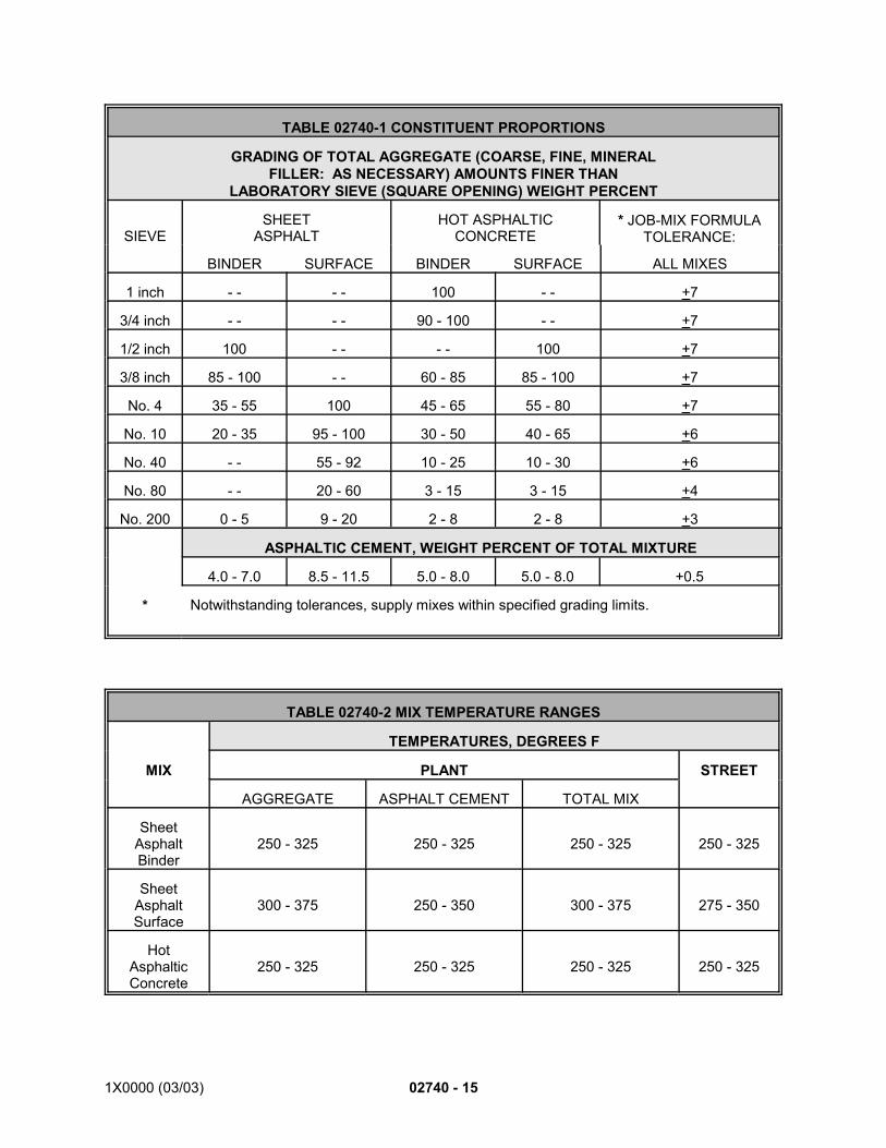
1X0000 (03/03) 02740 - 15
TABLE 02740-1 CONSTITUENT PROPORTIONS
GRADING OF TOTAL AGGREGATE (COARSE, FINE, MINERALFILLER: AS NECESSARY) AMOUNTS FINER THAN
LABORATORY SIEVE (SQUARE OPENING) WEIGHT PERCENT
SIEVESHEET
ASPHALTHOT ASPHALTIC
CONCRETE* JOB-MIX FORMULA
TOLERANCE:
BINDER SURFACE BINDER SURFACE ALL MIXES
1 inch - - - - 100 - - +7
3/4 inch - - - - 90 - 100 - - +7
1/2 inch 100 - - - - 100 +7
3/8 inch 85 - 100 - - 60 - 85 85 - 100 +7
No. 4 35 - 55 100 45 - 65 55 - 80 +7
No. 10 20 - 35 95 - 100 30 - 50 40 - 65 +6
No. 40 - - 55 - 92 10 - 25 10 - 30 +6
No. 80 - - 20 - 60 3 - 15 3 - 15 +4
No. 200 0 - 5 9 - 20 2 - 8 2 - 8 +3
ASPHALTIC CEMENT, WEIGHT PERCENT OF TOTAL MIXTURE
4.0 - 7.0 8.5 - 11.5 5.0 - 8.0 5.0 - 8.0 +0.5
* Notwithstanding tolerances, supply mixes within specified grading limits.
TABLE 02740-2 MIX TEMPERATURE RANGES
TEMPERATURES, DEGREES F
MIX PLANT STREET
AGGREGATE ASPHALT CEMENT TOTAL MIX
SheetAsphaltBinder
250 - 325 250 - 325 250 - 325 250 - 325
SheetAsphaltSurface
300 - 375 250 - 350 300 - 375 275 - 350
HotAsphalticConcrete
250 - 325 250 - 325 250 - 325 250 - 325
02740 - 16 1X0000 (03/03)
*1. Use second version of SECTION 02740 BITUMINOUS PAVEMENT for contracts where bituminouspavement work is performed within the jurisdiction of the District of Columbia except as noted. (Usefirst version for contracts where bituminous pavement work is performed outside the jurisdiction ofthe District of Columbia.)
END OF SECTION
SEE ENDNOTES BELOW. THEY ARE AN ESSENTIAL PART OF THIS SECTION UNTIL EDITED BYSECTION DESIGNER.
ENDNOTES:
1X0000 (03/03) 02750-1
SECTION 02750(Version 1)*1
CONCRETE PAVEMENT
PART 1 - GENERAL
1.01 DESCRIPTION:
A. This section specifies providing portland cement concrete pavement, plain or reinforced orboth, in conformance with the sections, lines and grades shown.
B. Related Work Specified Elsewhere:1. Base for pavements: Section 02725.2. Concrete reinforcement: Section 03200.3. Cast-in-place structural concrete: Section 03300.
1.02 SUBMITTALS:
Submit the following for approval in accordance with the General Requirements and with theadditional requirements as specified for each:
A. Shop Drawings:1. Joint devices.
B. Certification: As specified in Section 03300, including design mixes.
1.03 QUALITY ASSURANCE:
A. Codes, Regulations, Reference Standards and Specifications:1. Comply with codes and regulations of the jurisdictional authorities.2. AASHTO: M33, M74, M81, M148, M153, M171, M182, M194, M220, M227, T51,
T148.3. FS: TT-P-86, TT-S-00227.4. ASTM: A185, A370, A615, C33, C294, C920, D3405.
B. Concrete: Conform to quality assurance requirements as specified in Section 03300 and thissection.
C. Testing: Subject concrete for pavements to test procedures specified in Section 03300.
1.04 PRODUCT DELIVERY, STORAGE AND HANDLING:
A. Aggregates and Cement: As specified in Section 03300.
1.05 JOB CONDITIONS:
A. Environmental Requirements:1. Do not place concrete on frozen soil base.2. Apply joint sealer when the air temperature is 50F or higher.
B. Refrain from placing concrete while the temperature is lower than 40F or when bythe National Weather Service forecast it may be expected to reach 40F or lowerduring the 24-hour period following placement of concrete.
02750-2 1X0000 (03/03)
PART 2 - PRODUCTS
2.01 MATERIALS:
A. Subgrade Paper: AASHTO M74.
B. Polyethylene sheet and tape: AASHTO M171, white opaque for curing.
C. Wire Fabric: Welded steel-wire fabric, ASTM A185.
D. Bituminous Paint: AASHTO M81, Grade RC-250.
E. Joint Devices:1. Tie bars: ASTM A615, Grade 60.2. Tie rod assemblies: Tensile requirements of AASHTO M227, Grade 80 based on
measured cross-sectional area of unthreaded portion of bar when tested inassembled condition in accordance with ASTM A370.
3. Dowels:a. Plain round bars, AASHTO M227, Grade 80 coated with paint, FS TT-P-86,
Type I.b. Dowel sleeves in accordance with the following:
1) Snug fit with dowel bar.2) Closed end.3) Limit stop for dowel approximately one inch from closed end.4) Sufficient rigidity to prevent entry of fresh concrete and collapse
during construction.4. Hook bolt:
a. Material: As specified for dowels.b. Fabrication: As shown.
F. Grease for Dowels: Approved water-resistant grease.
G. Expansion Joint Materials:1. Preformed expansion joint fillers:
a. Bituminous: AASHTO M33.b. Cork: AASHTO M153, Type II.c. Preformed joint seals: AASHTO M220.
2. Expansion joint sealing compounds:a. Hot-poured: ASTM D3405 and when tested in accordance with AASHTO
T51 having ductility not less than 40 centimeter and flow at 140F not greaterthan one centimeter. Use of ground rubber scrap is prohibited.
b. Cold-applied: Single-component type, ASTM C920.c. Elastomeric: FS TT-S-00227, Type 1, Class A.
H. Burlap: AASHTO M182, Class 3 or 4.
I. Waterproof paper: AASHTO M171.
J. White burlap-polyethylene sheet shall conform to AASHTO Designation M171.
K. Liquid Membrane Forming Curing Compounds: AASHTO M148, Type 1, resin base, wax-free.
L. Concrete: Section 03300, Class 3500, air-entrained, with the following additionalrequirements:
1X0000 (03/03) 02750-3
1. Portland cement: Type I.2. Minimum cement content: Six bags per cubic yard of concrete.3. Maximum water content: Water/Cement ratio of 0.45 by weight.4. Air content: 6-1/2 percent plus-or-minus 1-1/2 percent by volume.5. Slump: 2-1/2 inches plus-or-minus 1/2 inch.6. Water reducing admixture: AASHTO M194, Type A or D as directed.7. Coarse aggregate:8. Size: ASTM C33 and as follows: 57; 67; 57 and 67; 57 and 4; 67 and 4; or 57, 67
and 4.9. Deleterious materials: Maximum amount of soft fragments, 2.0 percent by weight;
maximum amount of coal and lignite 0.25 percent by weight; and material passingSize 200 sieve 0.5 percent by weight.a. Maximum abrasion loss: 40 percent by weight.
10. Fine aggregate:a. Deleterious material: Maximum amount of friable particles, 0.5 percent by
weight; maximum amount of coal and lignite 0.25 percent by weight;material passing Size 200 sieve three percent maximum by weight.
11. For bridge decks and bridge sidewalks: Use only crushed trap rock aggregate, traprock to be diabase rock, ASTM C294.
M. High-Early-Strength Concrete: As specified for concrete and modified to produce high-early-strength concrete by one or a combination of the following methods.1. Substitution of Type III or Type I cement in approved mix.2. Addition of Type I cement to the approved mix, but so that the total cement does not
exceed eight bags per cubic yard of concrete.3. Addition of an approved accelerating admixture to approved mix as specified in
Section 03300.
PART 3 - EXECUTION
3.01 EQUIPMENT:
A. Provide appropriate equipment in sufficient quantity and sizes to perform work as specifiedand shown.
B. Maintain machinery and equipment on site in first class working condition. Provide necessarytools and supplies for maintenance.
C. Straightedges and Templates:1. Use metal straightedges, 10 feet long, rigidly constructed so as to prevent vertical
deflection exceeding 1/32 inch and fitted with handles for ease of use.2. Use templates, constructed so as to extend from form to form and to ride on form,
having adjustable tines spaced at six-inch intervals and rigidly constructed so as toprevent vertical deflection exceeding 1/32 inch.
3.02 BASE:
A. Check previously placed base for grade and crown with templates and straightedges forcompliance with tolerances specified in Section 02725.
B. Correct deficiencies in grade, contour and compaction.
C. Obtain approval of base prior to placing forms and impervious material.
3.03 SETTING FORMS:
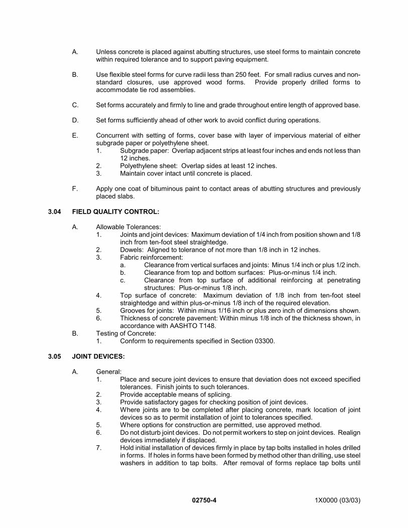
02750-4 1X0000 (03/03)
A. Unless concrete is placed against abutting structures, use steel forms to maintain concretewithin required tolerance and to support paving equipment.
B. Use flexible steel forms for curve radii less than 250 feet. For small radius curves and non-standard closures, use approved wood forms. Provide properly drilled forms toaccommodate tie rod assemblies.
C. Set forms accurately and firmly to line and grade throughout entire length of approved base.
D. Set forms sufficiently ahead of other work to avoid conflict during operations.
E. Concurrent with setting of forms, cover base with layer of impervious material of eithersubgrade paper or polyethylene sheet.1. Subgrade paper: Overlap adjacent strips at least four inches and ends not less than
12 inches.2. Polyethylene sheet: Overlap sides at least 12 inches.3. Maintain cover intact until concrete is placed.
F. Apply one coat of bituminous paint to contact areas of abutting structures and previouslyplaced slabs.
3.04 FIELD QUALITY CONTROL:
A. Allowable Tolerances:1. Joints and joint devices: Maximum deviation of 1/4 inch from position shown and 1/8
inch from ten-foot steel straightedge.2. Dowels: Aligned to tolerance of not more than 1/8 inch in 12 inches.3. Fabric reinforcement:
a. Clearance from vertical surfaces and joints: Minus 1/4 inch or plus 1/2 inch.b. Clearance from top and bottom surfaces: Plus-or-minus 1/4 inch.c. Clearance from top surface of additional reinforcing at penetrating
structures: Plus-or-minus 1/8 inch.4. Top surface of concrete: Maximum deviation of 1/8 inch from ten-foot steel
straightedge and within plus-or-minus 1/8 inch of the required elevation.5. Grooves for joints: Within minus 1/16 inch or plus zero inch of dimensions shown.6. Thickness of concrete pavement: Within minus 1/8 inch of the thickness shown, in
accordance with AASHTO T148.B. Testing of Concrete:
1. Conform to requirements specified in Section 03300.
3.05 JOINT DEVICES:
A. General:1. Place and secure joint devices to ensure that deviation does not exceed specified
tolerances. Finish joints to such tolerances.2. Provide acceptable means of splicing.3. Provide satisfactory gages for checking position of joint devices.4. Where joints are to be completed after placing concrete, mark location of joint
devices so as to permit installation of joint to tolerances specified.5. Where options for construction are permitted, use approved method.6. Do not disturb joint devices. Do not permit workers to step on joint devices. Realign
devices immediately if displaced.7. Hold initial installation of devices firmly in place by tap bolts installed in holes drilled
in forms. If holes in forms have been formed by method other than drilling, use steelwashers in addition to tap bolts. After removal of forms replace tap bolts until
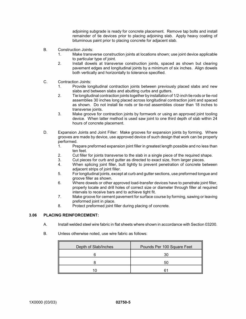
1X0000 (03/03) 02750-5
adjoining subgrade is ready for concrete placement. Remove tap bolts and installremainder of tie devices prior to placing adjoining slab. Apply heavy coating ofbituminous paint prior to placing concrete for adjacent slab.
B. Construction Joints:1. Make transverse construction joints at locations shown; use joint device applicable
to particular type of joint.2. Install dowels at transverse construction joints, spaced as shown but clearing
pavement edges and longitudinal joints by a minimum of six inches. Align dowelsboth vertically and horizontally to tolerance specified.
C. Contraction Joints:1. Provide longitudinal contraction joints between previously placed slabs and new
slabs and between slabs and abutting curbs and gutters.2. Tie longitudinal contraction joints together by installation of 1/2-inch tie rods or tie-rod
assemblies 30 inches long placed across longitudinal contraction joint and spacedas shown. Do not install tie rods or tie-rod assemblies closer than 18 inches totransverse joints.
3. Make groove for contraction joints by formwork or using an approved joint toolingdevice. When latter method is used saw joint to one third depth of slab within 24hours of concrete placement.
D. Expansion Joints and Joint Filler: Make grooves for expansion joints by forming. Wheregrooves are made by device, use approved device of such design that work can be properlyperformed.1. Prepare preformed expansion joint filler in greatest length possible and no less than
ten feet.2. Cut filler for joints transverse to the slab in a single piece of the required shape.3. Cut pieces for curb and gutter as directed to exact size, from larger pieces.4. When splicing joint filler, butt tightly to prevent penetration of concrete between
adjacent strips of joint filler.5. For longitudinal joints, except at curb and gutter sections, use preformed tongue and
groove filler as shown.6. Where dowels or other approved load-transfer devices have to penetrate joint filler,
properly locate and drill holes of correct size or diameter through filler at requiredintervals to receive bars and to achieve tight fit.
7. Make groove for cement pavement for surface course by forming, sawing or leavingpreformed joint in place.
8. Protect preformed joint filler during placing of concrete.
3.06 PLACING REINFORCEMENT:
A. Install welded steel wire fabric in flat sheets where shown in accordance with Section 03200.
B. Unless otherwise noted, use wire fabric as follows:
Depth of Slab/Inches Pounds Per 100 Square Feet
6 30
8 50
10 61
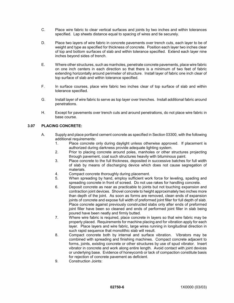
02750-6 1X0000 (03/03)
C. Place wire fabric to clear vertical surfaces and joints by two inches and within tolerancesspecified. Lap sheets distance equal to spacing of wires and tie securely.
D. Place two layers of wire fabric in concrete pavements over trench cuts, each layer to be ofweight and type as specified for thickness of concrete. Position each layer two inches clearof top and bottom surfaces of slab and within tolerance specified. Extend each layer nineinches beyond sides of trench.
E. Where other structures, such as manholes, penetrate concrete pavements, place wire fabricon one inch centers in each direction so that there is a minimum of two feet of fabricextending horizontally around perimeter of structure. Install layer of fabric one inch clear oftop surface of slab and within tolerance specified.
F. In surface courses, place wire fabric two inches clear of top surface of slab and withintolerance specified.
G. Install layer of wire fabric to serve as top layer over trenches. Install additional fabric aroundpenetrations.
H. Except for pavements over trench cuts and around penetrations, do not place wire fabric inbase course.
3.07 PLACING CONCRETE:
A. Supply and place portland cement concrete as specified in Section 03300, with the followingadditional requirements:1. Place concrete only during daylight unless otherwise approved. If placement is
authorized during darkness provide adequate lighting system.2. Prior to placing concrete around poles, manholes or other structures projecting
through pavement, coat such structures heavily with bituminous paint.3. Place concrete to the full thickness, deposited in successive batches for full width
of slab by means of discharging device which does not cause segregation ofmaterials.
4. Compact concrete thoroughly during placement.5. When spreading by hand, employ sufficient work force for leveling, spading and
spreading concrete in front of screed. Do not use rakes for handling concrete.6. Deposit concrete as near as practicable to joints but not touching expansion and
contraction joint devices. Shovel concrete to height approximately two inches morethan depth of the joint. As soon as forms are removed, clean ends of expansionjoints of concrete and expose full width of preformed joint filler for full depth of slab.Place concrete against previously constructed slabs only after ends of preformedjoint filler have been so cleaned and ends of performed joint filler in slab beingpoured have been neatly and firmly butted.
7. Where wire fabric is required, place concrete in layers so that wire fabric may beproperly placed. Requirements for machine placing and for vibration apply for eachlayer. Place layers and wire fabric, large wires running in longitudinal direction insuch rapid sequence that monolithic slab will result.
8. Compact concrete both by internal and surface vibration. Vibrators may becombined with spreading and finishing machines. Compact concrete adjacent toforms, joints, existing concrete or other structures by use of spud vibrator. Insertvibrator in concrete and work along entire length. Avoid contact with joint devicesor underlying base. Evidence of honeycomb or lack of compaction constitute basisfor rejection of concrete pavement as deficient.
9. Construction Joints:
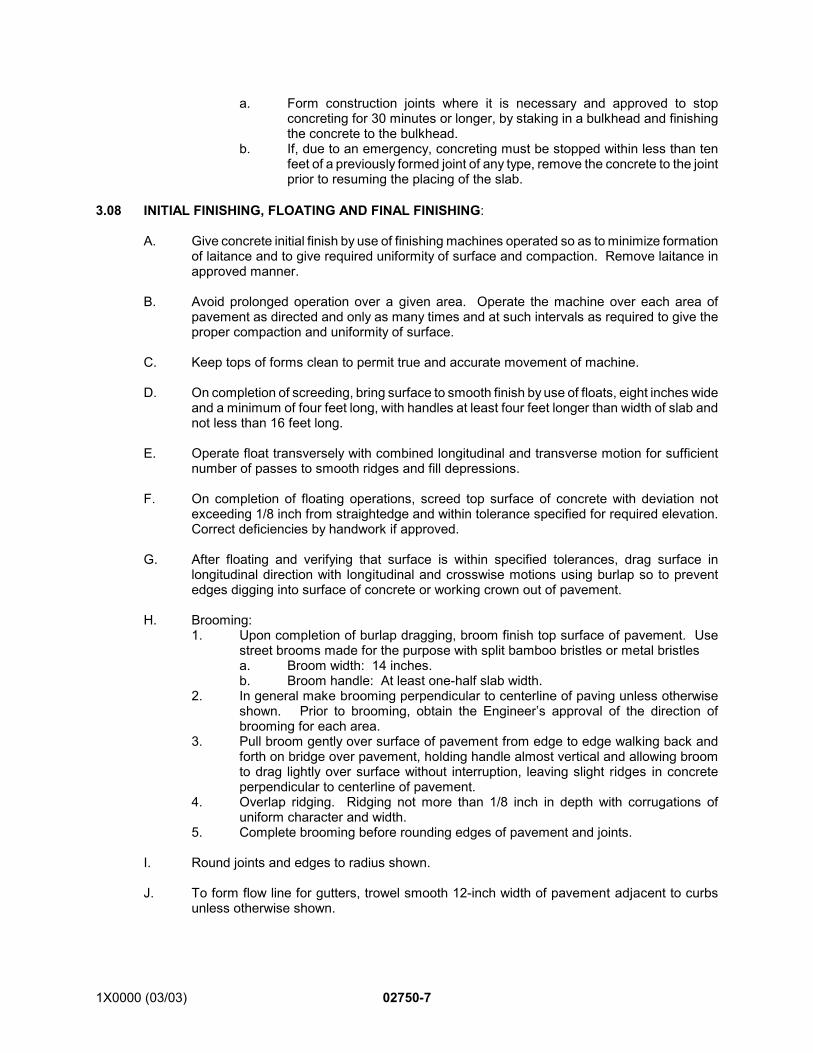
1X0000 (03/03) 02750-7
a. Form construction joints where it is necessary and approved to stopconcreting for 30 minutes or longer, by staking in a bulkhead and finishingthe concrete to the bulkhead.
b. If, due to an emergency, concreting must be stopped within less than tenfeet of a previously formed joint of any type, remove the concrete to the jointprior to resuming the placing of the slab.
3.08 INITIAL FINISHING, FLOATING AND FINAL FINISHING:
A. Give concrete initial finish by use of finishing machines operated so as to minimize formationof laitance and to give required uniformity of surface and compaction. Remove laitance inapproved manner.
B. Avoid prolonged operation over a given area. Operate the machine over each area ofpavement as directed and only as many times and at such intervals as required to give theproper compaction and uniformity of surface.
C. Keep tops of forms clean to permit true and accurate movement of machine.
D. On completion of screeding, bring surface to smooth finish by use of floats, eight inches wideand a minimum of four feet long, with handles at least four feet longer than width of slab andnot less than 16 feet long.
E. Operate float transversely with combined longitudinal and transverse motion for sufficientnumber of passes to smooth ridges and fill depressions.
F. On completion of floating operations, screed top surface of concrete with deviation notexceeding 1/8 inch from straightedge and within tolerance specified for required elevation.Correct deficiencies by handwork if approved.
G. After floating and verifying that surface is within specified tolerances, drag surface inlongitudinal direction with longitudinal and crosswise motions using burlap so to preventedges digging into surface of concrete or working crown out of pavement.
H. Brooming:1. Upon completion of burlap dragging, broom finish top surface of pavement. Use
street brooms made for the purpose with split bamboo bristles or metal bristlesa. Broom width: 14 inches.b. Broom handle: At least one-half slab width.
2. In general make brooming perpendicular to centerline of paving unless otherwiseshown. Prior to brooming, obtain the Engineer’s approval of the direction ofbrooming for each area.
3. Pull broom gently over surface of pavement from edge to edge walking back andforth on bridge over pavement, holding handle almost vertical and allowing broomto drag lightly over surface without interruption, leaving slight ridges in concreteperpendicular to centerline of pavement.
4. Overlap ridging. Ridging not more than 1/8 inch in depth with corrugations ofuniform character and width.
5. Complete brooming before rounding edges of pavement and joints.
I. Round joints and edges to radius shown.
J. To form flow line for gutters, trowel smooth 12-inch width of pavement adjacent to curbsunless otherwise shown.
02750-8 1X0000 (03/03)
K. Joint Work and Edging: Where there is an option of method for doing joint work, secureapproval for the method elected and use only that method.1. Perform joint work and edging when condition of concrete permits.2. Ensure that joints are within tolerances specified and that there is no perceptible lip
or depression other than rounding.3. Prepare clean grooves rounded to 1/4-inch radius with smooth even walls.4. Make grooves for expansion joints by forming. See requirements above for
expansion joints.5. For joints to be sealed with poured sealer, prepare grooves with dimensions as
shown and within tolerance specified. For joints to be sealed with preformedelastomeric seals, leave grooves of dimensions and within tolerances shown.Provide suitable gauges for checking dimensions.
6. Where joints in surface course are sealed with cold-poured joint sealer, breakbottom bond by placing polyethylene tape full width of groove, laid flat along top ofpreformed joint filler prior to joint sealing.
7. When using hot-poured or cold-applied joint sealer, use only equipment designedfor purpose. Hand-pouring pots are prohibited. Maintain material within temperaturerange recommended by manufacturer. Apply sealer when air temperature is asspecified. Construct so that resulting stripe is straight, neat, of uniform width andjoint is filled to 1/4 inch from top surface of pavement.
8. When placing elastomeric joint seals, use equipment and methods recommendedby manufacturer.
3.09 CURING:
A. Allow finished concrete to cure by one of the following methods for seven days or untilconcrete has developed flexural strength of 500 psi:1. Wet burlap: Cover pavement with double thickness of thoroughly wet burlap,
overlapping adjacent sheets by at least six inches. Maintain burlap in saturated stateby sprinkling until it is removed. Use only clean material free from holes.
2. Waterproof paper, polyethylene sheet or white burlap-polyethylene sheet: Placematerial so that adjacent sheets overlap by at least 12 inches. Secure materialalong side and ends so as to maintain reasonably airtight seal.
3. Use approved liquid-membrane curing compounds as recommended bymanufacturer, using equipment designed for purpose.
3.10 REMOVAL OF FORMS:
A. Remove forms as soon as condition of concrete permits, but in no case sooner than 12 hoursafter placement.
B. When the temperature is below 40F, leave forms in place for at least 48 hours or as directed.
3.11 COLD WEATHER CONSTRUCTION:
A. Whenever, by the National Weather Service forecast for the locality, the temperature maybe expected to reach 50F or lower during the 24-hour period following placement concretemix, include an approved accelerating admixture in the concrete mix as specified in Section03300.
B. Place concrete when temperature conditions are as specified, unless otherwise directed. Ifplacing of concrete is so directed, in addition to adding an accelerating admixture heataggregates, water or both, so that mix when placed is not less than 55F nor more than 90F.Do not exceed 140F for mixing water and 150F for aggregates.
1X0000 (03/03) 02750-9
*1. Use first version of SECTION 02750 CONCRETE PAVEMENT for contracts where concretepavement work is performed outside the jurisdiction of the District of Columbia. (Use second version forcontracts where concrete pavement work is performed within the jurisdiction of the District of Columbia.)
END OF SECTION
C. As soon as concrete has hardened sufficiently to prevent marring, cover pavement surfaceand edges with dry burlap, building paper or other approved material and subsequent layerof at least six inches of dry hay, straw or other approved material. Maintain such protectionfor at least three days or until field tests indicate that concrete has attained required strength.
D. During low temperatures, install truck-mixed concrete immediately upon delivery.
E. When temperature by National Weather Service forecast will be 40F or lower during the 72-hour period following placement of concrete, do not use membrane curing compound.
3.12 HOT WEATHER CONSTRUCTION:
A. When by National Weather Service forecast, temperature will be 90F or higher during the 24-hour period following placement of concrete, cover pavement by wet-burlap method for first24 hours, after which curing may be completed by one of the specified methods.
3.13 PROTECTION OF CONCRETE PAVEMENT:
A. Obtain approval prior to permitting use of completed pavement by public and constructiontraffic.
3.14 DEFICIENT PAVEMENT:
A. Where directed, remove and replace with new materials or correct concrete pavement thatdoes not meet requirements.
SEE ENDNOTES BELOW. THEY ARE AN ESSENTIAL PART OF THIS SECTION UNTIL EDITED BYSECTION DESIGNER.
1X0000 (08/01) 02750 - 1
SECTION 02750(Version 2)*1
CONCRETE PAVEMENT
PART 1 - GENERAL
1.01 DESCRIPTION:
A. This section specifies providing portland cement concrete pavements complete in place asshown.
B. Related Work Specified Elsewhere:1. Base for pavements: Section 02725.2. Concrete reinforcement: Section 03200.3. Cast-in-place structural concrete: Section 03300.
1.02 SUBMITTALS:
Submit the following for approval in accordance with the General Requirements with the additionalrequirements as specified for each:
A. Shop Drawings:1. Joint devices.
B. Certification: As specified in Section 03300, including design mixes.
1.03 QUALITY ASSURANCE:
A. Codes, Regulations, Reference Standards and Specifications:1. Comply with codes and regulations of the jurisdictional authorities.2. AASHTO: M33, M74, M81, M148, M153, M171, M182, M194, M220, M227, T51
T148.3. FS: SS-S-164, SS-S-195, TT-P-86, TT-S-00227.4. ASTM: A185, A370, A615, C33, C294, C920.
B. Concrete: Conform to quality assurance requirements as specified in Section 03300 and thissection.
C. Testing: Subject concrete for pavements to test procedures specified in Section 03300.
1.04 PRODUCT DELIVERY, STORAGE AND HANDLING:
A. Aggregates and Cement: As specified in Section 03300.
1.05 JOB CONDITIONS:
A. Environmental Requirements:1. Do not place concrete on frozen soil base.2. Apply joint sealer when the air temperature is 50F or higher.
B. Refrain from placing concrete while the temperature is lower than 40F or when by theNational Weather Service forecast it may be expected to reach 40F or lower during the 24-hour period following placement of concrete.
02750 - 2 1X0000 (08/01)
PART 2 - PRODUCTS
2.01 MATERIALS:
A. Subgrade Paper: AASHTO M74.
B. Polyethylene sheet and tape: AASHTO M171, white opaque for curing.
C. Welded Wire Fabric: Welded steel-wire fabric, ASTM A185.
D. Bituminous Paint: AASHTO M81, Grade RC-250.
E. Joint Devices: Use joint devices which are so designed that, when under the load of freshconcrete, the parts will deviate no more than 1/4 inch from the position shown and not morethan 1/8 inch from the specified tolerances, and that the finish joints can be constructed tothese same tolerances. Provide joint devices complete with accessories, approvedsupporting devices, and installing devices and equipment. 1. Tie bars: ASTM A615, Grade 60.2. Tie rod assemblies: Tensile requirements of AASHTO M227, Grade 80 based on
measured cross-sectional area of unthreaded portion of bar when tested inassembled condition in accordance with ASTM A370.
3. Dowels:a. Plain round bars, AASHTO M227, Grade 80 coated with paint, FS TT-P-86,
Type I.b. Dowel sleeves in accordance with the following:
1) Snug fit with dowel bar.2) Closed end.3) Limit stop for dowel approximately one inch from closed end.4) Sufficient rigidity to prevent entry of fresh concrete and collapse
during construction.4. Grease for Dowels: Approved water-resistant graphite grease.5. Preformed joint fillers: AASHTO M153, Type II.6. Preformed Plank: Rigid plank of asphalt hardboard or similar material approved by
the Engineer.
F. Joint Sealer Materials:1. Joint sealing compound: Materials so proportioned that joints will be satisfactorily
sealed from moisture and other foreign matter. Add appropriate tinting duringmanufacture, if necessary, to produce a black color.a. Hot-poured joint sealing compound for joints in concrete pavement: FS SS-
S-164 except the use of ground rubber scrap is prohibited. Ductility of notless than 40 centimeter in accordance with AASHTO T51; flow at 140F notgreater than 1.0 centimeter.
b. Cold-applied joint sealing compound for joints in concrete pavement:FS SS-S-195.
c. Joint sealing compound for joints between concrete pavement and otherstructures: FS TT-S-00227.
G. Preformed joint seals: AASHTO M220.
H. Burlap: AASHTO M182, Class 3.
I. Waterproof paper: AASHTO M171.
J. White burlap-polyethylene sheet shall conform to AASHTO Designation M171.
1X0000 (08/01) 02750 - 3
K. Liquid Membrane Forming Curing Compounds: AASHTO M148, Type 1, resin base, wax-free.
L. Concrete: Section 03300, Class 3500, air-entrained, amended as follows:1. Portland cement: Type I.2. Minimum cement content: Six bags per cubic yard of concrete. 3. Maximum water content: 0.45 maximum water cement ratio. 4. Air content: 6-1/2 percent plus-or-minus 1-1/2 percent by volume.5. Slump: 2-1/2 inches plus-or-minus 1/2 inch.6. Water reducing admixture: AASHTO M194, Type A or D as directed.7. Coarse aggregate:
a. Size: ASTM C33 Size No. 67 or a combination of Size No. 4 and Size No.67.
b. Deleterious materials: Maximum amount of soft fragments, 2.0 percent byweight; maximum amount of coal and lignite 0.25 percent by weight; andmaterial passing Size 200 sieve 0.5 percent by weight.
c. Maximum abrasion loss: 40 percent by weight.8. Fine aggregate:
a. Deleterious material: Maximum amount of friable particles, 0.5 percent byweight; maximum amount of coal and lignite 0.25 percent by weight;material passing Size 200 sieve three percent maximum by weight.
9. For bridge decks and bridge sidewalks: Use only crushed trap rock aggregate, traprock to be diabase rock, ASTM C294.
M. High-Early-Strength Concrete: As specified for concrete and modified to produce high-early-strength concrete by one or a combination of the following methods.1. Substitution of Type III or Type I cement in approved mix.2. Addition of Type I cement to the approved mix, but so that the total cement does not
exceed eight bags per cubic yard of concrete.3. Addition of an approved accelerating admixture to approved mix as specified in
Section 03300.
PART 3 - EXECUTION
3.01 EQUIPMENT:
A. General: See General Provision’s Article on equipment.1. Provide suitable equipment in sufficient quantity and sizes to perform work as
specified and shown.2. Maintain machinery and equipment on site in first class working condition. Provide
necessary tools and supplies for maintenance.3. The term EQUIPMENT includes such specialized devices and tools that are
customarily used in the construction of concrete pavements. The requirements forequipment given are not intended to be complete; rather, the intent is thatcharacteristic equipment be used to produce certain of the required results. Thesuitability of the equipment is a determination made by the Engineer that theequipment will produce the required results.
A. Concrete Spreading Machines: Power driven spreaders capable of spreading concrete tothe full width and depth specified as it is delivered and as follows:1. Standard-width machines with adjustments up to five feet.2. Controls conveniently grouped in easy reach of the operator.3. Multiple speeds in both reverse and forward gear.
02750 - 4 1X0000 (08/01)
4. Capable of spreading concrete to both the depth specified for reinforcement and thefull thickness of the slab, without segregation and without interfering with the jointsor reinforcement.
5. Not disturbing the forms due to lateral pressure of the spreading operation; theweight of the machines of such amount and so distributed as not to cause settlementof the forms.
6. Equipped with dismountable rims to be used when operating on concrete. 7. Provided with suitable means to keep material off the wheel and the top of the forms
or slab.8. Spreading accomplished by either a screw, blade, or other suitable device of the
reversing type, followed by a strike-off screed; the strike-off screed adjustable to thespecified crown and section.
B. Internal Vibrators Operated Independently of Spreading or Finishing Machines: Useapproved type of internal vibrators such as the spud-type, for compacting pavement concreteat joints and edges, operating at a frequency capable of producing at least 5,000 pulsationsper minute, and with sufficient cable to permit being moved to any location directed by theEngineer. Do not use vibrators of such weight as to be unwieldy in application.
C. Concrete Finishing Machines:1. Power-driven and of the transverse-screed type.2. Equipped with traction wheel or wheels with dismountable rims to be used when
operating on concrete.3. Equipped with two screeds, maintained in the best possible condition and adjustment
throughout their use: Front screed used for striking off excess concrete to exactgrade and crown; the rear screed used for finishing and smoothing operation.
4. Screeds constructed of steel, be capable of being adjusted to the specified crosssection, and be of such rigidity as to produce the specified crown and cross section.
5. Each screed of the floating or suspended type, at least 1-1/2 feet longer than thewidth between the forms, and easily and quickly adjustable to the width required.
6. Both machine and screeds are to have variable speeds and independentlycontrolled.
7. The weight of the machines of such amount and so distributed as not to causesettlement of the forms upon which operated.
8. Provided with suitable means to keep material off the wheel and the top of the formsor slab.
D. Straightedges: Ten feet long, made of metal with handles suitable for ease of use, andrigidly constructed so that there will be no deflection exceeding 1/32 inch.
E. Templates: Constructed to extend from form to form and to ride on the form, equipped withadjustable tines spaced at six-inch intervals, and rigidly constructed that there will be nodeflection exceeding 1/32 inch.
3.02 BASE:
A. Base Preparation: In accordance with Section 02725.
B. Check previously placed base for grade and crown with templates and straightedges forcompliance with tolerances specified in Section 02725.
C. Correct deficiencies in grade, contour and compaction.
D. Obtain approval of base prior to placing forms and impervious material.
3.03 SETTING FORMS:
1X0000 (08/01) 02750 - 5
A. Unless concrete is placed against abutting structures, use steel forms to maintain concretewithin required tolerance and to support paving equipment.
B. Use flexible steel forms for curve radii less than 250 feet. For small radius curves and non-standard closures, use approved wood forms. Provide properly drilled forms toaccommodate tie rod assemblies.
C. Set forms accurately and firmly to line and grade throughout entire length of approved base.
D. Set forms sufficiently ahead of other work to avoid conflict during operations.
E. Concurrent with setting of forms, cover base with layer of impervious material of eithersubgrade paper or polyethylene sheet.1. Subgrade paper: Overlap adjacent strips at least four inches and ends not less than
12 inches.2. Polyethylene sheet: Overlap sides at least 12 inches.3. Maintain cover intact until concrete is placed.
F. Apply one coat of bituminous paint to contact areas of abutting structures and previouslyplaced slabs.
3.04 FIELD QUALITY CONTROL:
A. Allowable Tolerances:1. Joints and joint devices: Maximum deviation of 1/4 inch from position shown and 1/8
inch from ten-foot steel straightedge.2. Dowels: Aligned to tolerance of not more than 1/8 inch in 12 inches.3. Fabric reinforcement:
a. Clearance from vertical surfaces and joints: Minus 1/4 inch or plus 1/2 inch.b. Clearance from top and bottom surfaces: Plus-or-minus 1/4 inch.c. Clearance from top surface of additional reinforcing at penetrating
structures: Plus-or-minus 1/8 inch.4. Top surface of concrete: Maximum deviation of 1/8 inch from ten-foot steel
straightedge and within plus-or-minus 1/8 inch of the required elevation.5. Grooves for joints: Within minus 1/16 inch or plus zero inch of dimensions shown.6. Thickness of concrete pavement: Within minus 1/8 inch of the thickness shown, in
accordance with AASHTO T148.
B. Testing of Concrete:1. Conform to requirements specified in Section 03300.
3.05 JOINT DEVICES:
A. General:1. Place and secure joint devices to ensure that deviation does not exceed specified
tolerances. Finish joints to such tolerances.2. Provide acceptable means of splicing.3. Provide satisfactory gages for checking position of joint devices.4. Where joints are to be completed after placing concrete, mark location of joint
devices so as to permit installation of joint to tolerances specified.5. Where options for construction are permitted, use approved method.6. Do not disturb joint devices. Do not permit workers to step on joint devices. Realign
devices immediately if displaced.7. Hold initial installation of devices firmly in place by tap bolts installed in holes drilled
in forms. If holes in forms have been formed by method other than drilling, use steelwashers in addition to tap bolts. After removal of forms replace tap bolts until
02750 - 6 1X0000 (08/01)
adjoining subgrade is ready for concrete placement. Remove tap bolts and installremainder of tie devices prior to placing adjoining slab. Apply heavy coating ofbituminous paint prior to placing concrete for adjacent slab.
B. Construction.1. Longitudinal: The longitudinal joint at a previously placed slab and the joint between
a slab and abutting curb and gutter are longitudinal construction joints.a. For these joints, with the exception of the ones at the curb and gutter
sections, use a tongue-and-groove joint of an isosceles trapezoidal sectionone inch in height with the bases two inches and 2-1/2 inches, respectively;with the groove located as shown
b. Tie the separately constructed slab sections together by the installation oflongitudinal tie devices.
c. The groove for concrete pavement for surface course may be made byforming or sawing as specified below, or by preformed plank left in place.
d. Coat edges of the slab first constructed with heavy coat of bituminous paintprior to placing concrete for the adjacent slab.
2. Transverse joints: Make transverse construction joints only at a planned transverseexpansion or contraction joint. Accordingly, have transverse construction jointdevices conform to the requirements for the particular type of joint.
C. Contraction Joints:1. Provide longitudinal contraction joints between previously placed slabs and new
slabs and between slabs and abutting curbs and gutters.a. Tie longitudinal contraction joints together by installation of 1/2-inch tie rods
or tie-rod assemblies 30 inches long placed across longitudinal contractionjoint and spaced as shown. Do not install tie rods or tie-rod assembliescloser than 18 inches to transverse joints.
b. Make groove for contraction joints by formwork, sawing or leaving filler inplace.
D. Expansion Joints and Joint Filler: 1. Make grooves for expansion joints by forming. Where grooves are made by device,
use approved device of such design that work can be properly performed.a. Prepare preformed expansion joint filler in greatest length possible and no
less than ten feet.b. Cut filler for joints transverse to the slab in a single piece of the required
shape.c. Cut pieces for curb and gutter as directed to exact size, from larger pieces.d. When splicing joint filler, butt tightly to prevent penetration of concrete
between adjacent strips of joint filler.e. For longitudinal joints, except at curb and gutter sections, use preformed
tongue and groove filler as shown.f. Where dowels or other approved load-transfer devices have to penetrate
joint filler, properly locate and drill holes of correct size or diameter throughfiller at required intervals to receive bars and to achieve tight fit.
g. Make groove for cement pavement for surface course by forming, sawingor leaving preformed joint in place.
h. Protect preformed joint filler during placing of concrete.
3.06 PLACING REINFORCEMENT:
A. Install welded steel wire fabric in flat sheets where shown in accordance with Section 03200.
B. Unless otherwise noted, use wire fabric as follows:
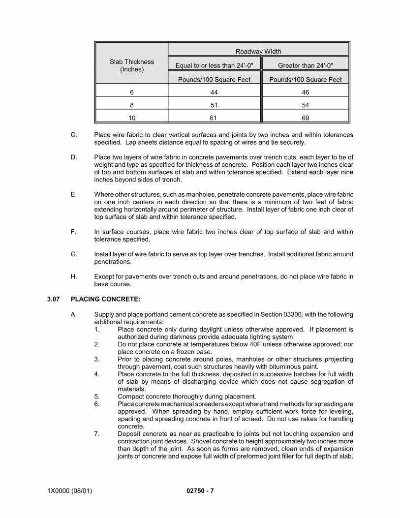
1X0000 (08/01) 02750 - 7
Slab Thickness(Inches)
Roadway Width
Equal to or less than 24'-0" Greater than 24'-0"
Pounds/100 Square Feet Pounds/100 Square Feet
6 44 46
8 51 54
10 61 69
C. Place wire fabric to clear vertical surfaces and joints by two inches and within tolerancesspecified. Lap sheets distance equal to spacing of wires and tie securely.
D. Place two layers of wire fabric in concrete pavements over trench cuts, each layer to be ofweight and type as specified for thickness of concrete. Position each layer two inches clearof top and bottom surfaces of slab and within tolerance specified. Extend each layer nineinches beyond sides of trench.
E. Where other structures, such as manholes, penetrate concrete pavements, place wire fabricon one inch centers in each direction so that there is a minimum of two feet of fabricextending horizontally around perimeter of structure. Install layer of fabric one inch clear oftop surface of slab and within tolerance specified.
F. In surface courses, place wire fabric two inches clear of top surface of slab and withintolerance specified.
G. Install layer of wire fabric to serve as top layer over trenches. Install additional fabric aroundpenetrations.
H. Except for pavements over trench cuts and around penetrations, do not place wire fabric inbase course.
3.07 PLACING CONCRETE:
A. Supply and place portland cement concrete as specified in Section 03300, with the followingadditional requirements:1. Place concrete only during daylight unless otherwise approved. If placement is
authorized during darkness provide adequate lighting system.2. Do not place concrete at temperatures below 40F unless otherwise approved; nor
place concrete on a frozen base.3. Prior to placing concrete around poles, manholes or other structures projecting
through pavement, coat such structures heavily with bituminous paint.4. Place concrete to the full thickness, deposited in successive batches for full width
of slab by means of discharging device which does not cause segregation ofmaterials.
5. Compact concrete thoroughly during placement.6. Place concrete mechanical spreaders except where hand methods for spreading are
approved. When spreading by hand, employ sufficient work force for leveling,spading and spreading concrete in front of screed. Do not use rakes for handlingconcrete.
7. Deposit concrete as near as practicable to joints but not touching expansion andcontraction joint devices. Shovel concrete to height approximately two inches morethan depth of the joint. As soon as forms are removed, clean ends of expansionjoints of concrete and expose full width of preformed joint filler for full depth of slab.
02750 - 8 1X0000 (08/01)
Place concrete against previously constructed slabs only after ends of preformedjoint filler have been so cleaned and ends of performed joint filler in slab beingpoured have been neatly and firmly butted.
8. Where wire fabric is required, place concrete in layers so that wire fabric may beproperly placed. Requirements for machine placing and for vibration apply for eachlayer. Place layers and wire fabric, large wires running in longitudinal direction insuch rapid sequence that monolithic slab will result.
9. Compact concrete both by internal and surface vibration. Vibrators may becombined with spreading and finishing machines. Compact concrete adjacent toforms, joints, existing concrete or other structures by use of spud vibrator. Insertvibrator in concrete and work along entire length. Avoid contact with joint devicesor underlying base. Evidence of honeycomb or lack of compaction constitute basisfor rejection of concrete pavement as deficient.
10. Construction Joints:a. Form construction joints where it is necessary and approved to stop
concreting for 30 minutes or longer, by staking in a bulkhead and finishingthe concrete to the bulkhead.
b. If, due to an emergency, concreting must be stopped within less than tenfeet of a previously formed joint of any type, remove the concrete to the jointprior to resuming the placing of the slab.
3.08 INITIAL FINISHING, FLOATING AND FINAL FINISHING:
A. Give concrete initial finish by use of finishing machines operated so as to minimize formationof laitance and to give required uniformity of surface and compaction. Remove laitance inapproved manner.
B. Avoid prolonged operation over a given area. Operate the machine over each area ofpavement as directed and only as many times and at such intervals as required to give theproper compaction and uniformity of surface.
C. Keep tops of forms clean to permit true and accurate movement of machine.
D. On completion of screeding, bring surface to smooth finish by use of floats, eight inches wideand a minimum of four feet long, with handles at least four feet longer than width of slab andnot less than 16 feet long.
E. Operate float transversely with combined longitudinal and transverse motion for sufficientnumber of passes to smooth ridges and fill depressions.
F. On completion of floating operations, screed top surface of concrete with deviation notexceeding 1/8 inch from straightedge and within tolerance specified for required elevation.Correct deficiencies by handwork if approved.
G. After floating and verifying that surface is within specified tolerances, drag surface inlongitudinal direction with longitudinal and crosswise motions using burlap so to preventedges digging into surface of concrete or working crown out of pavement.
H. Brooming:1. Upon completion of burlap dragging, broom finish top surface of pavement. Use
street brooms made for the purpose with split bamboo bristles or metal bristles.a. Broom width: 14 inches.b. Broom handle: At least one-half slab width.
2. In general make brooming perpendicular to centerline of paving unless otherwiseshown. Prior to brooming, obtain the Engineer’s approval of the direction ofbrooming for each area.
1X0000 (08/01) 02750 - 9
3. Pull broom gently over surface of pavement from edge to edge walking back andforth on bridge over pavement, holding handle almost vertical and allowing broomto drag lightly over surface without interruption, leaving slight ridges in concreteperpendicular to centerline of pavement.
4. Overlap ridging. Ridging not more than 1/8 inch in depth with corrugations ofuniform character and width.
5. Complete brooming before rounding edges of pavement and joints.
I. Round joints and edges to radius shown.
J. To form flow line for gutters, trowel smooth 12-inch width of pavement adjacent to curbsunless otherwise shown.
K. Joint Work and Edging: Where there is an option of method for doing joint work, secureapproval for the method elected and use only that method.1. Perform joint work and edging when condition of concrete permits.2. Ensure that joints are within tolerances specified and that there is no perceptible lip
or depression other than rounding.3. Prepare clean grooves rounded to 1/4-inch radius with smooth even walls.4. Make grooves for expansion joints by forming. See requirements above for
expansion joints.5. For joints to be sealed with poured sealer, prepare grooves with dimensions as
shown and within tolerance specified. For joints to be sealed with preformedelastomeric seals, leave grooves of dimensions and within tolerances shown.Provide suitable gauges for checking dimensions.
6. Where joints in surface course are sealed with cold-poured joint sealer, breakbottom bond by placing polyethylene tape full width of groove, laid flat along top ofpreformed joint filler prior to joint sealing.
7. When using hot-poured or cold-applied joint sealer, use only equipment designedfor purpose. Hand-pouring pots are prohibited. Maintain material within temperaturerange recommended by manufacturer. Apply sealer when air temperature is asspecified. Construct so that resulting stripe is straight, neat, of uniform width andjoint is filled to 1/4 inch from top surface of pavement.
8. When placing elastomeric joint seals, use equipment and methods recommendedby manufacturer.
3.09 CURING:
A. Allow finished concrete to cure by one of the following methods for seven days or untilconcrete has developed flexural strength of 500 psi:1. Wet burlap: Cover pavement with double thickness of thoroughly wet burlap,
overlapping adjacent sheets by at least six inches. Maintain burlap in saturated stateby sprinkling until it is removed. Use only clean material free from holes.
2. Waterproof paper, polyethylene sheet or white burlap-polyethylene sheet: Placematerial so that adjacent sheets overlap by at least 12 inches. Secure materialalong side and ends so as to maintain reasonably airtight seal.
3. Use approved liquid-membrane curing compounds as recommended bymanufacturer, using equipment designed for purpose.
B. Obtain approval of the Engineer for the curing method elected and use only that method.
3.10 REMOVAL OF FORMS:
A. Remove forms as soon as condition of concrete permits, but in no case sooner than 12 hoursafter placement.
02750 - 10 1X0000 (08/01)
*1. Use second version of SECTION 02750 CONCRETE PAVEMENT for contracts where concretepavement work is performed within the jurisdiction of the District of Columbia. (Use first version forcontracts where concrete pavement work is performed outside the jurisdiction of the District ofColumbia.)
END OF SECTION
B. When the temperature is below 40F, leave forms in place for at least 48 hours or as directed.
3.11 COLD WEATHER CONSTRUCTION:
A. Whenever, by the National Weather Service forecast for the locality, the temperature maybe expected to reach 50F or lower during the 24-hour period following placement concretemix, include a Type C accelerating admixture in the concrete mix as specified in Section03300. The accelerating admixture shall comply with AASHTO M 194, Type C, except thatit shall contain not more than 500 parts per million chloride ion.
B. Place concrete when temperature conditions are as specified, unless otherwise directed. Ifplacing of concrete is so directed, in addition to adding an accelerator heat aggregates, wateror both, so that mix when laid is not less than 55F nor more than 90F. Do not exceed 140Ffor mixing water and 150F for aggregates.
C. As soon as concrete has hardened sufficiently to prevent marring, cover pavement surfaceand edges with dry burlap, building paper or other approved material and subsequent layerof at least six inches of dry hay, straw or other approved material. Maintain such protectionfor at least three days or until field tests indicate that concrete has attained required strength.
D. During low temperatures, install truck-mixed concrete immediately upon delivery.
E. When temperature by National Weather Service forecast will be 40F or lower during the 72-hour period following placement of concrete, do not use membrane curing compound.
3.12 HOT WEATHER CONSTRUCTION:
A. When by National Weather Service forecast, temperature will be 90F or higher during the 24-hour period following placement of concrete, cover pavement by wet-burlap method for first24 hours, after which curing may be completed by one of the specified methods.
3.13 PROTECTION OF CONCRETE PAVEMENT:
A. Obtain approval prior to permitting use of completed pavement by public and constructiontraffic.
3.14 DEFICIENT PAVEMENT:
A. Where directed, remove and replace with new materials or correct concrete pavement thatdoes not meet requirements.
SEE ENDNOTES BELOW. THEY ARE AN ESSENTIAL PART OF THIS SECTION UNTIL EDITED BYSECTION DESIGNER.
1X0000 (03/03) 02765-1
SECTION 02765
PAVEMENT MARKINGS
PART 1 - GENERAL
1.01 DESCRIPTION:
A. This section specifies providing pavement markings and striping.
1.02 SUBMITTALS:
A. Submit the following for approval in accordance with the General Requirements and with theadditional requirements as specified for each:1. Samples:
a. Paint: One quart of each color.b. Spheres: Two pounds.c. Thermoplastic compound: Ten pounds of each color.d. Preformed plastic markings: Five each of plain and reflective, each three
inches wide by one-foot long.2. Certification.
1.03 QUALITY ASSURANCE:
A. Codes, Regulations, Reference Standards and Specifications:1. Comply with codes and regulations of the jurisdictional authorities.2. AASHTO: M249-79.3. USDOT/FHWA: Manual on Uniform Traffic Control Devices for Streets and
Highways.4. Federal Test Method Standard 141.5. FED STD: 595.6. FS: TT-P-85, TT-B-1325.7. ASTM: D638.
1.04 PRODUCT DELIVERY, STORAGE AND HANDLING:
A. Deliver materials in factory-sealed containers plainly marked as follows:1. Manufacturer's name and address.2. Location of plant.3. Material.4. Color of material.5. Amount of contents.6. Date of manufacturer and lot number.
1.05 JOB CONDITIONS:
A. Environmental Requirements:1. Traffic zone paint:
a. Apply only when ambient air temperature is above 40F and temperature ofsurface to be painted is above 45F.
b. If pavement is wet, allow surface to dry for eight hours minimum aftersurface appears dry.
c. Do not apply glass spheres in strong windy conditions.2. Extruded thermoplastic compound:
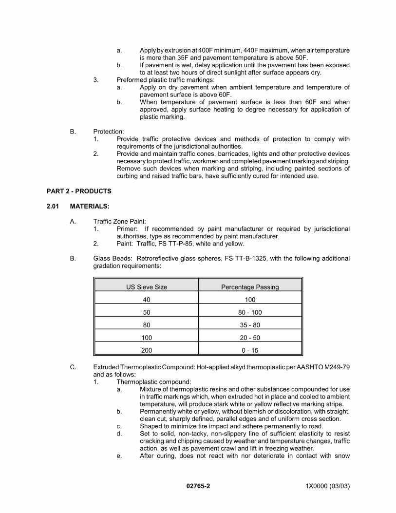
02765-2 1X0000 (03/03)
a. Apply by extrusion at 400F minimum, 440F maximum, when air temperatureis more than 35F and pavement temperature is above 50F.
b. If pavement is wet, delay application until the pavement has been exposedto at least two hours of direct sunlight after surface appears dry.
3. Preformed plastic traffic markings:a. Apply on dry pavement when ambient temperature and temperature of
pavement surface is above 60F.b. When temperature of pavement surface is less than 60F and when
approved, apply surface heating to degree necessary for application ofplastic marking.
B. Protection:1. Provide traffic protective devices and methods of protection to comply with
requirements of the jurisdictional authorities.2. Provide and maintain traffic cones, barricades, lights and other protective devices
necessary to protect traffic, workmen and completed pavement marking and striping.Remove such devices when marking and striping, including painted sections ofcurbing and raised traffic bars, have sufficiently cured for intended use.
PART 2 - PRODUCTS
2.01 MATERIALS:
A. Traffic Zone Paint:1. Primer: If recommended by paint manufacturer or required by jurisdictional
authorities, type as recommended by paint manufacturer.2. Paint: Traffic, FS TT-P-85, white and yellow.
B. Glass Beads: Retroreflective glass spheres, FS TT-B-1325, with the following additionalgradation requirements:
US Sieve Size Percentage Passing
40 100
50 80 - 100
80 35 - 80
100 20 - 50
200 0 - 15
C. Extruded Thermoplastic Compound: Hot-applied alkyd thermoplastic per AASHTO M249-79and as follows:1. Thermoplastic compound:
a. Mixture of thermoplastic resins and other substances compounded for usein traffic markings which, when extruded hot in place and cooled to ambienttemperature, will produce stark white or yellow reflective marking stripe.
b. Permanently white or yellow, without blemish or discoloration, with straight,clean cut, sharply defined, parallel edges and of uniform cross section.
c. Shaped to minimize tire impact and adhere permanently to road.d. Set to solid, non-tacky, non-slippery line of sufficient elasticity to resist
cracking and chipping caused by weather and temperature changes, trafficaction, as well as pavement crawl and lift in freezing weather.
e. After curing, does not react with nor deteriorate in contact with snow
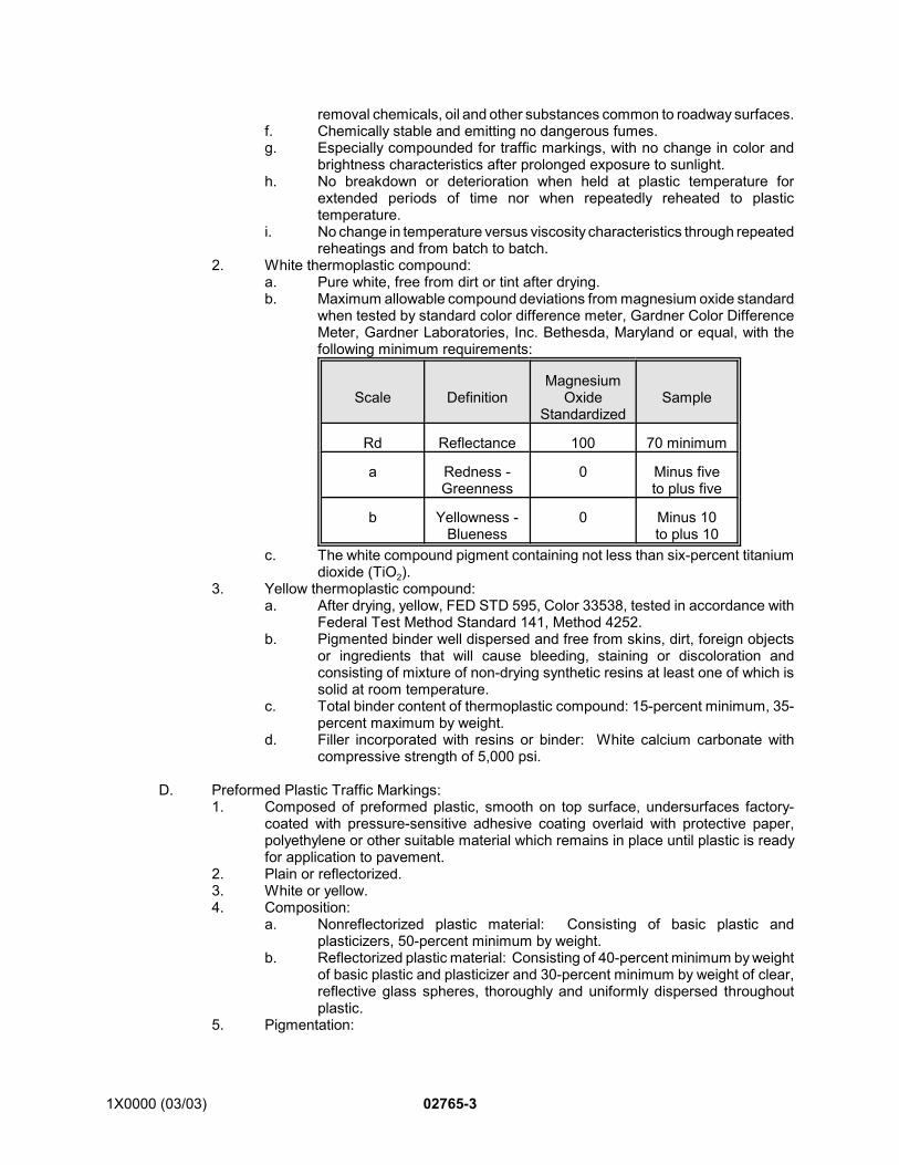
1X0000 (03/03) 02765-3
removal chemicals, oil and other substances common to roadway surfaces.f. Chemically stable and emitting no dangerous fumes.g. Especially compounded for traffic markings, with no change in color and
brightness characteristics after prolonged exposure to sunlight.h. No breakdown or deterioration when held at plastic temperature for
extended periods of time nor when repeatedly reheated to plastictemperature.
i. No change in temperature versus viscosity characteristics through repeatedreheatings and from batch to batch.
2. White thermoplastic compound:a. Pure white, free from dirt or tint after drying.b. Maximum allowable compound deviations from magnesium oxide standard
when tested by standard color difference meter, Gardner Color DifferenceMeter, Gardner Laboratories, Inc. Bethesda, Maryland or equal, with thefollowing minimum requirements:
Scale DefinitionMagnesium
OxideStandardized
Sample
Rd Reflectance 100 70 minimum
a Redness -Greenness
0 Minus fiveto plus five
b Yellowness -Blueness
0 Minus 10to plus 10
c. The white compound pigment containing not less than six-percent titaniumdioxide (TiO2).
3. Yellow thermoplastic compound:a. After drying, yellow, FED STD 595, Color 33538, tested in accordance with
Federal Test Method Standard 141, Method 4252.b. Pigmented binder well dispersed and free from skins, dirt, foreign objects
or ingredients that will cause bleeding, staining or discoloration andconsisting of mixture of non-drying synthetic resins at least one of which issolid at room temperature.
c. Total binder content of thermoplastic compound: 15-percent minimum, 35-percent maximum by weight.
d. Filler incorporated with resins or binder: White calcium carbonate withcompressive strength of 5,000 psi.
D. Preformed Plastic Traffic Markings:1. Composed of preformed plastic, smooth on top surface, undersurfaces factory-
coated with pressure-sensitive adhesive coating overlaid with protective paper,polyethylene or other suitable material which remains in place until plastic is readyfor application to pavement.
2. Plain or reflectorized.3. White or yellow.4. Composition:
a. Nonreflectorized plastic material: Consisting of basic plastic andplasticizers, 50-percent minimum by weight.
b. Reflectorized plastic material: Consisting of 40-percent minimum by weightof basic plastic and plasticizer and 30-percent minimum by weight of clear,reflective glass spheres, thoroughly and uniformly dispersed throughoutplastic.
5. Pigmentation:
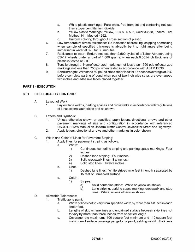
02765-4 1X0000 (03/03)
a. White plastic markings: Pure white, free from tint and containing not lessthan six-percent titanium dioxide.
b. Yellow plastic markings: Yellow, FED STD 595, Color 33538, Federal TestMethod 141, Method 4252.
c. Uniform coloring throughout cross section of plastic.6. Low-temperature stress resistance: No indication of breaking, chipping or cracking
when sample of specified thickness is abruptly bent to right angle after beingimmersed in water at 32F for 30 minutes.
7. Resistance to wear: Endure not less than 2,500 cycles of a Taber Abraser, usingCS-17 wheels under a load of 1,000 grams, when each 0.001-inch thickness ofplastic is tested at 21C.
8. Tensile strength: Nonreflectorized markings not less than 1500 psi; reflectorizedmarkings not less than 750 psi when tested in accordance with ASTM D638.
9. Bond strength: Withstand 50-pound static shear load for 15 seconds average at 21Cbefore complete parting of bond when pair of two-inch wide strips are overlappedtwo inches and adhesive faces placed together.
PART 3 - EXECUTION
3.01 FIELD QUALITY CONTROL:
A. Layout of Work:1. Lay out lane widths, parking spaces and crosswalks in accordance with regulations
of jurisdictional authorities and as shown.
B. Letters and Symbols:1. Unless otherwise shown or specified, apply letters, directional arrows and other
pavement markings of size and configuration in accordance with referencedUSDOT/FHWA Manual on Uniform Traffic Control Devices for Street and Highways.
2. Apply letters, directional arrows and other markings in color shown.
C. Width and Color of Lines for Pavement Striping:1. Apply lines for pavement striping as follows:
a. Width:1) Continuous centerline striping and parking space markings: Four
inches.2) Dashed lane striping: Four inches.3) Solid crosswalk lines: Six inches.4) Solid stop lines: Twelve inches.
b. Lines:1) Dashed lane lines: White stripes nine feet in length separated by
15 feet of unmarked surface.c. Color:
1) Stripes:a) Solid centerline stripe: White or yellow as shown.b) Lane striping, parking space marking, crosswalk and stop
lines: White, unless otherwise shown.D. Allowable Tolerances:
1. Traffic-zone paint:a. Width of lines not to vary from specified width by more than 1/8 inch in each
linear foot.b. Lengths of skip or lane lines and unpainted surface between skip lines not
to vary by more than three inches from specified length.c. Coverage rate maximum: 100 square feet minimum and 110 square feet
maximum of surface coverage per gallon of paint, yielding wet-film thickness
1X0000 (03/03) 02765-5
of 0.015 inches minimum.d. Coverage rate of glass spheres: Ten pounds per gallon of paint minimum.
2. Extruded thermoplastic compound:a. Thickness of stripe: 90 to 125 mils.b. Rate of application of binder-sealer: Between 800 linear feet and 1,000
linear feet per gallon for four-inch wide lines. For lines of other widths, applyin proportion based on such rate.
3. Preformed plastic traffic markings:a. Thickness: 0.095 inch, minus 0.005 inch or plus 0.010 inch.b. Width: Four inches, plus-or-minus 1/8-inch per 12-inch length.
4. Painting of curbing and raised traffic bars:a. Wet-film thickness: 0.015 inches minimum.
3.02 APPLICATION:
A. Traffic Zone Paint:1. Equipment:
a. Use equipment suitable for mechanical application of paint and glassspheres.
b. Apply paint with atomizing spray machines designed for striping to applystripes of uniform cross section, and thickness, at specified coverage withclean-cut edges permitting easy and accurate adjustment of width and rateof application as well as immediate shutoff.
c. Use automatic mechanical equipment designed and constructed todistribute glass spheres in uniform pattern and at prescribed coverageregardless of variation in speed of travel. Equipment may be integral partof striping machines or self-contained unit designed for attachment tostriping machines, so that glass spheres will be applied immediatelyfollowing application of paint. Use equipment designed and constructed topermit adjustment of coverage rate.
2. Method of application:a. Schedule marking and striping operations to permit paint to set and harden
before roadway is opened to traffic.b. Allow hot laid bituminous material to cool, prior to beginning striping
operations.c. Remove foreign matter from surfaces prior to painting.d. Apply pigmented binder and glass spheres, mix and thin pigmented binder
in accordance with manufacturer's recommendations.e. Apply glass spheres uniformly, immediately following application of paint.
Do not premix paint and spheres.f. Apply pavement markings accurately with straight, clean-cut, sharply
defined parallel edges and of uniform cross section.g. Clean striping machines as often as necessary to ensure application of
markings of specified quality and physical requirements.
B. Extruded Thermoplastic Compound:1. Equipment:
a. Master kettle:1) Minimum capacity: 800 pounds of melted compound.2) Double oil jacket.3) Thermostatic controls.4) Approved heating device.5) Temperature gauges for oil and compound.6) Integrally mounted chopping device to chop and drop solid
compound into kettle.
02765-6 1X0000 (03/03)
b. Liner:1) Use liners with self-contained heat source, such as propane heater,
capable of maintaining compound at drawing temperature of notless than 420F as well as radiant heater installed over die for samepurpose.
2) For installation of crosswalk lines, stop lines and solid center lines,use liner with capacity of approximately 150 pounds and automaticsphere dispenser capable of distributing reflective spheres onsurface of line while still plastic.
3) For centerline and lane line installation, use mobile unit equippedto automatically install dashed lines in combinations of line and skipup to 40 feet and for application of reflective spheres as specifiedfor smaller liner.
4) Provide for varying die widths in liner to produce specified linewidths, including shaping die cutoff device to provide clean, squareends at beginnings and ends of lines.
2. Application of binder-sealer:a. Before applying binder-sealer or thermoplastic compound, prepare roadway
surface by buffing and cleaning or other appropriate method.b. Where thermoplastic stripe is to be installed, spray surfaces with binder
sealer consisting of two parts epoxy and one-part hardener-catalystimmediately prior to installation of compound.
c. Mix binder-sealer fresh each day. Do not premix.3. Application of thermoplastic compound:
a. Apply compound in colors shown and at locations shown.b. Do not use pans and aprons to control width of lines.c. Use equipment including extrusion dies capable of maintaining compound
at specified extrusion temperature and density and capable of producingstripe of specified width.
4. Application of glass spheres:a. Perform reflectorizing of thermoplastic compound by immediate application
of glass spheres to specified density.b. Perform reflectorizing so that completed line registers not less than 55 on
Hunter Nite Visibility Meter.
C. Preformed Plastic Traffic Markings:1. Prepare roadway surface by removing dirt, dust, oily substances and other foreign
matter before installing plastic markings.2. Do not install plastic marking on wet or damp pavement.3. Make installations in neat, workmanlike manner with ends and edges of successive
strips of material even.4. Position center and lane markings using chalk as guides.5. Installation on sheet-asphalt surfaces:
a. When plastic markings are to be installed on new sheet-asphalt surfaces,install while asphalt is still hot and immediately before final rolling isperformed.
b. As part of final rolling operation, position and embed plastic marking intosurface.
c. To install plastic markings on existing sheet asphalt, accurately locate andpress marking into place and obtain final bond by at least two longitudinalpasses of ten-ton roller.
6. Installation on asphaltic-concrete surfaces:a. Install as specified for sheet-asphalt surfaces except apply prime coat
recommended by manufacturer of plastic markings to pavement surfaceprior to installation of markings.
7. Installation on portland-cement concrete pavement:
1X0000 (03/03) 02765-7
a. Seal surface of concrete pavement with quick-setting primer to reducecapillary action and improve bond between marking and pavement surface.
b. Otherwise install as specified for sheet-asphalt pavement.
D. Painting of Curbing and Raised Traffic Bars:1. Paint curbing and raised traffic bars with traffic-zone paint.2. Clean surfaces to be painted of dirt, dust, laitance, oil or other foreign substances.3. Allow 14 days minimum after installation of portland-cement concrete before
painting.4. Curbing:
a. Paint top and front of curbing in locations shown with one coat ofnonreflectorized traffic-zone paint as specified.
5. Raised traffic bars:a. Paint surfaces, except bottom of raised traffic bars with one coat of white
traffic-zone paint and apply glass spheres before paint has hardened.b. Apply paint and glass spheres as specified.
END OF SECTION
1X0000 (03/03) 02772-1
SECTION 02772
CURBS, GUTTERS AND WALKS
PART 1 - GENERAL
1.01 DESCRIPTION:
A. This section specifies providing curbs, gutters, curb and gutters and walks. *1
B. This section specifies providing walks, curbs, gutters, curb and gutters, coping curbs andintegral curbs. *2
C. Related Work Specified Elsewhere:1. Grading, excavating and backfilling: Section 02320.2. Base course for pavements: Section 02725.3. Concrete pavement: Section 02750.4. Concrete reinforcement: Section 03200.5. Cast-in-place structural concrete: Section 03300.6. Granite: Section 04415.
1.02 SUBMITTALS:
A. Submit the following for approval in accordance with the General Requirements and with theadditional requirements as specified for each:1. Documentation:
a. Where stone curb is provided by street or highway jurisdiction, submit bill ofstone curb materials prior to picking up materials at designated storagefacility and transporting to site.
1.03 QUALITY ASSURANCE:
A. Codes, Regulations, Reference Standards and Specifications:1. Comply with codes and regulations of the jurisdictional authorities.2. ASTM: C979.
1.04 PRODUCT DELIVERY AND HANDLING:
A. Handle stone so as to maintain curb intact with exposed faces unmarred.
PART 2 - PRODUCTS
2.01 MATERIALS:
A. Concrete: Section 02750 and as specified in this section.
B. Carbon Black:1. Emulsified: At least 25 percent by weight standard carbon-gas black colloidally
dispersed in liquid medium so that when one part of product is stirred into ten partsof water, resulting liquid, after standing undisturbed for 72 hours, is uniformly coloredand contains no fillers nor other material that would adversely affect quality orappearance of concrete.
2. Powder:a. Concrete grade carbon black, meeting the requirements of ASTM C979.
02772-2 1X0000 (03/03)
b. Carbon black powder to disperse in water without floating and to be capableof uniform dispersion in plastic concrete.
C. Joint Devices: 1. In accordance with Section 02750, with the following additional requirements:
a. Dowels: 14 inches long, 3/4-inch diameter for curb and gutter and 1/2-inchdiameter for sidewalk.
b. Plates for construction joints and planes of weakness: 14-gauge galvanizedsheet metal cut to section as necessary.
D. Expansion Joint Materials: 1. In accordance with Section 02750, with the following additional requirements:
a. Preformed joint filler for stone curb, 1/4-inch thick; otherwise, 1/2-inch thick,subject to specified construction requirements.
E. Granite Curb: Section 04415 and as specified in this section.
F. Polyethylene Tape: Section 02750.
2.02 MIXES:
A. Mix exposed aggregate surface course concrete comprising by volume, one part portlandcement to three parts granite aggregate or gravel, crushed gravel or crushed stoneaggregate as shown, with sand added to form workable mix.
B. Where concrete walks are shown to be darkened, add 1/2 pound of emulsified carbon blackor 1/3 pound of carbon powder per bag of portland cement.
2.03 FABRICATION AND MANUFACTURING:
A. Fabrication of Granite Curbing:1. Drill holes are prohibited, unless otherwise specified.2. Straight granite curbstone:
a. Width: Eight inches plus-or-minus 1/8 inch at top surface.b. Front face: Between 12 inches and 14 inches deep.c. Batter: One-inch per foot to depth equal to reveal plus two inches.d. Length: Random, three feet minimum.
3. Radius curb up to and including 100 feet: Radius to have same cross sectiondimensions as straight curb and cut true to radius ordered. Radius curb to be notless than three feet in length measured on arc.
4. Radius curb greater than 100 feet through 200 feet: Radius to consist of straightsections not exceeding five feet in length with the ends cut to form radial joints.
5. The top surface of curbstone to be finished with four-cut or 550-shot finish, but notboth, to approximately true plane, with no projection or depression greater than 1/8inch.
6. Front face finished same as top surface for depth of reveal plus two inches, exceptthat sawn finish will be acceptable alternate, with no projection or depression greaterthan 1/8 inch. Remaining depth of front face may be rough cut with depressions orprojections not exceeding 1-1/2 inches.
7. Arris line between top and face to have 1/4-inch bullnose.8. Bottom surfaces to have no projection or depression greater than 1-1/2 inches.
1X0000 (03/03) 02772-3
9. Back surfaces to be sawn or split approximately at right angles to plane of topsurface. No projection or depression greater than 1/4 inch will be allowed for adistance of four inches from top. Remaining distance to have no projection ordepression greater than 1-1/2 inches. Drill holes will be permitted in back surfaceif they do not show in top arris line.
PART 3 - EXECUTION
3.01 FIELD QUALITY CONTROL:
A. Allowable Dimensional Tolerances:1. Concrete surfaces constructed in accordance with the following:
a. Plus-or-minus 3/16 inch of elevation shown.b. Deviation: 1/8-inch maximum from steel straightedge as specified in
Section 02750.
3.02 BASE:
A. Ensure that previously placed base is satisfactorily compacted and free from loose material.
B. Have base approved prior to placing forms and base covering.
C. Correct deficiencies in grade, contour and compaction.
3.03 FORMS:
A. Place forms as specified in Section 02750.
3.04 JOINT DEVICES AND CONTRACTION JOINTS:
A. General Requirements:1. Place joint devices and contraction joints as specified in Section 02750.2. Where work abuts concrete pavement, adjust spacing of joints so that joints of same
type coincide with transverse joints of concrete pavement.3. Width of preformed expansion joint filler: Same as thickness of concrete pavement
minus 3/4 inch.4. Concrete curb, gutter and curb and gutter:
a. Place two dowels in each joint between eight and twelve inches apart; forcurb and gutter place one of the dowels four inches from back of curb. Forcurb and gutter abutting concrete pavements, complete partial tie rodassemblies in slab. Place preformed expansion joint filler in single piecedepressed 1/2-inch below finished surface.
b. For curves of 100 feet radius or less, space expansion joints equally atintervals of approximately 15 feet; for radii greater than 100 feet spaceexpansion joints at intervals of 45 feet, with contraction joints at intervals of15 feet. Form contraction joints, with plates left in place, depressed 1/2-inchbelow finished surface.
c. Where placed in curves of 100 feet radius or less, stop reinforcing steel twoinches clear of expansion joints.
5. Sidewalk:a. Place 1/2-inch preformed expansion joint material between sidewalks and
curb where sidewalks are constructed between permanent structure andcurb.
b. Place transverse expansion joints at intervals of 45 feet. *3
02772-4 1X0000 (03/03)
c. Place transverse expansion joints at intervals of 45 feet, unless otherwiseshown. *4
d. Provide dowels in expansion joint spaced at two-foot intervals, clearingedges of sidewalk by one foot. Where sidewalks intersect, place expansionjoints in each sidewalk for full width along extension of back edges.
6. Uniform Joint Spacing: For the entire length of each straight or curved run ofsidewalk or curb to be placed, lay out the work and adjust joint spacing to provideintervals of equal dimension between joints, including grooves, unless otherwiseshown.
3.05 CONCRETE AND WIRE FABRIC:
A. Place concrete and wire fabric in accordance with applicable requirements of Section 02750except that top layer of fabric over trench-cuts to clear top surface by 1-1/2 inches, plus-or-minus 1/4-inch tolerance.
B. Place pipe for weep holes through curbs for rain leaders from building downspouts whereshown.
3.06 STONE CURB:
A. Excavating and backfilling in accordance with Section 02320.
B. Place no-slump concrete as setting bed.
C. Ram stone curb into proper position in setting bed and set to line and grade.
D. Where stone curb ties into existing curb, align exposed abutting surfaces.
E. Place preformed expansion joint filler at each joint.
3.07 FINISHING CONCRETE CURB, GUTTER AND CURB AND GUTTER:
A. Remove curb and face forms as soon as condition of concrete permits and perform finishingwork on exposed surfaces.
B. Finish face edge of curb to one-inch radius. Finish other edges to 1/4-inch radius.
C. Provide steel troweled finish followed by brushing with fine-hair brush.
D. Remove other forms when condition of concrete permits, but no sooner than 12 hours afterplacing. Rub surfaces with carborundum stone where necessary.
3.08 FINISHING SIDEWALK:
A. Work on Authority Property:1. Strike off and screed top surfaces so that resulting surface is smooth and within
specified tolerances.2. As soon as condition of work permits, perform joint work, edging and marking.3. Finish edges to 1/4-inch radius.4. Scoring pattern: Unless otherwise shown, as follows:
a. Expansion joints: Install on 45-foot centers. For the entire length of eachstraight or curved run of sidewalk to be placed, layout the work and adjustjoint spacing to provide intervals of equal dimension between joints,including grooves, unless otherwise shown.
1X0000 (03/03) 02772-5
b. Contraction joints: Make transverse grooves 1/3 depth of the concrete atapproximately nine-foot equal intervals between expansion jointsperpendicular to longitudinal grooves.
c. Control joints: Make transverse grooves 1/2-inch deep at approximatelythree foot equal intervals between contraction joints perpendicular tolongitudinal grooves.
d. Make longitudinal grooves 1/2-inch deep at approximately three foot equalintervals between and parallel to sides of sidewalk.
5. Finish surface with final light broom finish with fine-hair broom.6. Construct wheel chair ramps at locations shown.7. Remove forms when condition of concrete permit, but no sooner than 12 hours after
placement. Rub surfaces with carborundum stone where necessary.
B. Non-Authority Work:1. In accordance with codes and regulations of the jurisdictional authorities.
3.09 CURING:
A. In accordance with Section 02750, except that liquid membrane curing compounds not to beused on curb of curb and gutter when temperatures tend to go lower than 40F within 24 hoursafter application.
B. Do not use liquid membrane curing compounds on exposed aggregate concrete or darkenedconcrete surfaces.
3.10 SEALING JOINTS:
A. Immediately prior to sealing joints, place polyethylene tape width of groove flat on preformedexpansion joint filler.
B. Seal expansion joints in concrete curb, gutter and curb and gutter with poured joint sealer inconformance with Section 02750. Do not seal expansion joints in sidewalk and stone curb.
3.11 HIGH EARLY STRENGTH CONCRETE:
A. Use high-early-strength concrete in accordance with Section 02750 when approved.
3.12 CORES:
A. Where directed, provide test cores in accordance with Section 02750.
3.13 PROTECTION OF THE WORK:
A. Protect new work in accordance with Section 02750.
3.14 DEFICIENT WORK:
A. Remove and replace with new materials or correct as directed work which does not meetspecified requirements.
3.15 INTEGRAL CURBS: *5
A. Pour integral curbs with the pavement slab.
02772-6 1X0000 (03/03)
*1. Use first version of 1.01 A. for contracts where curb, gutter and walk work is performed outside thejurisdiction of Alexandria, Virginia.
*2. Use second version of 1.01 B. modification for contracts where curb, gutter and walk work isperformed within the jurisdiction of Alexandria, Virginia.
*3. Use first version of 3.04 A.5.b. for contracts where curb, gutter and walk work is performed outsidethe jurisdiction of Alexandria, Virginia.
*4. Use second version of 3.04 A.5.c. modification for contracts where curb, gutter and walk work isperformed within the jurisdiction of Alexandria, Virginia.
*5. Add Article 3.15 including A. for contracts where curb, gutter and walk work is performed within thejurisdiction of Alexandria, Virginia.
END OF SECTION
SEE ENDNOTES BELOW. THEY ARE AN ESSENTIAL PART OF THIS SECTION UNTIL EDITED BYSECTION DESIGNER.
1X0000 (11/07) 02820-1
SECTION 02820
FENCING
PART 1 - GENERAL
1.01 DESCRIPTION:
A. This section specifies providing chain-link fencing, gates and fan guards.
B. Related W ork Specified Elsewhere:
1. Cast-in-place Structural Concrete: Section 03300.
2. Grounding: Section 16060.
1.02 SUBMITTALS:
A. Submit the following for approval in accordance with the General Requirements and with the
additional requirements as specified for each:
1. Shop Drawings:
a. Manufacturer’s product data and installation instructions for fence, posts,
fabric, gates, hardware and accessories.
b. Site plan with fence showing locations of bracing, fan guards, gates, ground
rods, depression closures and other special fence construction.
c. Details of gates, depression closures and other special construction
showing fabrication and installation.
d. Details for installation of accessories.
2. Samples:
a. Chain link fabric: One of each width and type, each 24 inches long.
b. Posts, railing, braces, gate frames: One of each size and type, each 24
inches long.
c. Truss rod and turnbuckle: One each.
d. Tension wire: One, 24 inches long.
e. Barbed wire: One, 24 inches long.
f. Tension bar: One, 24 inches long.
g. Gate corner assembly: One.
h. Fabric ties: Four each.
i. Rail and brace ends and post caps: Two each.
j. Barbed wire extension arms: One each.
k. Other materials and accessories: One each.
3. Certification.
1.03 QUALITY ASSURANCE:
A. Codes, Regulations, Reference Standards and Specifications:
1. Comply with codes and regulations of the jurisdictional authorities.
2. AW S: D1.1.
3. MS: MIL-P-21035.
4. FS: FF-T-791, RR-F-191/2D, RR-F-191/3D, RR-F-191/4D.
5. ASTM: A121, A392, A413/A413M-01, C1107/C1107M-07a, F668.
02820-2 1X0000 (11/07)
1.04 JOB CONDITIONS:
A. Right of Access to Adjacent Private Property: As shown.
PART 2 - PRODUCTS
2.01 MATERIALS:
A. Fabric:
1. Steel, hot-dip galvanized after weaving, ASTM A392; Class 2 coating, two-inch
mesh, No. 9 gauge wire, height shown, both top and bottom selvage twisted and
barbed unless otherwise indicated on Contract Drawings. *1
2. PVC-coated steel: ASTM F668 Class 2b; two-inch mesh, 0.148-inch diameter zinc-
coated steel core wire, height as shown, black color PVC; top and bottom selvages
twisted and barbed, unless otherwise shown on Contract Drawings.
B. Posts, Top Rails and Braces:
1. FS RR-F-191/3D, with the following additional requirements:
a. Posts: Class 1, Grade. Size in accordance with Table I unless otherwise
shown.
b. Top rails: Class 1, Grade A; Size SP1.
c. Bracing: Class 1, Grade A; Size SP1.
d. Color coating: W here PVC-coated fabric is specified, provide matching
PVC color ASTM F668 Class 2b coating.
C. Accessories:
1. FS RR-F-191/4D, with the following additional requirements:
a. Hot-dip galvanized, unless otherwise specified.
b. W ire ties:
1) Fabric: No. 9-gauge steel.
2) Tension wire: No. 11-gauge steel.
c. Tension wire: No 7-gauge Steel. *1
d. Color coating: W here PVC-coated fabric is specified, provide matching
PVC color ASTM F668 Class 2b coating.
D. Barbed W ire:
1. ASTM A121, Chain Link Fence Grade,12-1/2 gauge steel wire with 14-gauge, four-
point round barbs, five inches on center.
E. Turnbuckle:
1. FS FF-T-791, Type 1, Form 1, Class 8, Size 3/8 by six, hexagonal heads, UNC
threads, hot-dip galvanized. W here PVC-coated fabric is required, provide matching
PVC color coating thermally fused to the galvanized steel substrate.
F. Latch:
1. Plunger bar full height of gate, to engage stop at double gates.
G. Security Chain:
1. ASTM A413, Grade 43 High Test Chain, case-hardened carbon-steel, 3/8-inch
diameter; hot-dipped galvanized at exterior locations.
1X0000 (11/07) 02820-3
H. Padlock:
1. W MATA Station areas - Corbin Russwin, Catalog No. PL5090 IC high security or
equal. All keys are to be turned over to the Engineer or W MATA Representative.
a. Removable interchangeable core; with two keys, keyed and master-keyed
as directed.
b. Body: Solid extruded brass.
c. Six-pin tumblers.
d. Shackle: Hardened steel, zinc-plated, 2-5/8 inch shackle length, ball bearing
locking heel and toe.
2. W MATA Track & Line chain-link fence gates areas - Master Lock #5KA, Key A389
with two keys. All keys are to be turned over to the Engineer or W MATA
Representative.
I. Concrete: Section 03300, Class 3500, air-entrained
J. Grout: Non-shrink, in accordance with ASTM C1107.
K. High Zinc-Dust Content Paint: MS MIL-P-21035.
2.02 SWING-TYPE GATES:
A. Provide swing-type gates, size as indicated on the Contract Drawings, complete with latches,
stops (if required by the manufacturer), keepers, hinges and three strands of above the fabric
(if shown on the Contract Drawings).
B. Conform to Federal Specifications RR-F-191/2D, Single Swing Type I, Double Swing Type
II, and as follows:
1. Hot-dipped galvanized.
2. Fabrication:
a. Fabricate gate perimeter frame from Class 1, Size SP2 pipe per Federal
Standard RR-F-191/3D.
b. Fabric: Same fabric as used on the fence. Attach fabric securely to the gate
frame at intervals not exceeding 15 inches.
c. Barbed wire: As specified in 2.1. D above.
d. Fan Guard: Materials and fabrication as specified for fencing.
3. Hardware:
a. Hinges: Two or more galvanized steel or malleable iron, to suit the gate size:
non-lift type, offset to permit 180 degrees opening.
b. Latch: Galvanized steel or malleable iron, combination type with provision
for padlock.
c. Gate stops and center rest: Manufacturers’ standard.
2.03 CANTILEVERED SLIDE GATE:
A. Conform to Federal Specification RR-F-192/2D, Type III.
B. Barbed W ire: As specified in 2.01 D. above.
02820-4 1X0000 (11/07)
PART 3 - EXECUTION
3.01 FENCE INSTALLATION:
A. Perform necessary clearing, grubbing, excavation and filling to provide clear line-of-fence
runs.
B. Set posts in concrete footings, sized as shown. All end, corner, pull and intermediate posts
are to be embedded a m inimum of 3 foot below final grade. Footing depth shall be a
minimum of 3 feet 6 inches.
C. Extend concrete to two inches above ground line at posts and slope to drain away from
posts. Form top 12 inches of footing, with remainder poured against excavated hole.
D. Space posts at 10 feet maximum and eight feet minimum on centers. Place additional posts
at each abrupt change in grade.
E. W here rock is encountered, drill holes two inches deeper than depth shown and two inches
greater than outside diameter of post. After post is placed as shown and specified, and
supported, fill remaining void with one-to-three grout mixture of cement and sand.
F. W here fence is located on concrete structure, weld post to base plate, thickness and size as
shown on Contract Drawings. Erect fence post truly vertical, where necessary using shims
of approved alloy. Secure to structure with anchor bolts; number, diameter and length as
shown on Contract Drawings. Fill void under base plate with non-shrink grout. Bolts, base
plate and weld to be hot-dipped galvanized.
G. Space pull posts at approximately 500-foot intervals for straight runs and at each vertical
angle point. Install corner posts at each horizontal angle point. Provide corner, end and pull
posts with horizontal braces and tie rods on each side of posts extending to and connecting
to adjacent line posts.
H. After posts are installed and grout has set, install top rail or tension wire and securely anchor
at ends and to line posts before hanging fabric.
I. Secure ends of fabric by tension bars threaded through loops in fabric and secured to posts
by bands with bolts and nuts or other approved devices.
J. Attach fabric outside framing system, away from Authority property. Stretch fabric by
securing one end and applying sufficient tension by mechanical fence stretchers. Fasten
fabric to line posts, tension wire and top railing with tie wires at spacing shown.
K. Hold bottom of fabric as uniformly as possible to, but in no case to exceed, two inches above
finished grade.
L. Provide barbed wire where shown. Install support arms at 45 degrees upward and outward
from Authority property; extend corner, gate and end posts as shown. Stretch barbed wire
to remove kinks and sags and secure to bracket arms, using tension bands for attachment
to posts.
1X0000 (11/07) 02820-5
*1. Please verify that Standard Drawings conform to the revised Specifications for Section 02820;
particularly that Utility Standard Drawing ST-U-34 contains Note 8 stating that fabric on Type A & A-1 fences
less than 72 inches high have both top & bottom selvages knuckled, and that Note 8 is referenced on
applicable section of CHART; and contains notes to Details 2 & 3 indicating maximum height of bottom
tension wire above grade is 6 inches.
END OF SECTION
M. Install gates, gate stops and fan guards as shown.
N. Set gate stops in concrete accurately so that plunger can be fully engaged.
O. Furnish one chain with one padlock for each gate.
P. Grounding: Section 16060.
3.02 GATE INSTALLATION
A. Install gates plumb, level and secure for full opening without interference. Install ground-set
items in concrete for anchorage, as detailed on the Contract Drawings. Adjust the hardware
for smooth operation and lubricate where necessary.
B. Attach barbed wire as shown on the Contract Drawings.
3.03 DEFECTIVE WORK:
A. Remove and replace fencing which is improperly located and is not true to line and grade,
and posts which are not plumb.
B. Repair damaged galvanizing by thoroughly wire brushing damaged area to remove loose and
cracked zinc coating, and paint with two coats of high zinc-dust content paint. Allow first coat
to dry thoroughly before applying second coat.
PART 4 -MEASUREMENT AND PAYMENT
4.01 MEASUREMENT
A. Measurement of work specified in this Section will be made in the following manner:
1. No separate measurement.
4.02 PAYMENT
A. Compensation for work specified in this Section will be made in the following manner:
1. Included in the price of the work of which it is a part.
SEE ENDNOTES BELOW. THEY ARE AN ESSENTIAL PART OF THIS SECTION UNTIL EDITED BY
SECTION DESIGNER.
ENDNOTES

02820-6 1X0000 (11/07)
1X0000 (03/03) 02845-1
SECTION 02845
TRAFFIC CONTROL DEVICES
PART 1 - GENERAL
1.01 DESCRIPTION:
A. This section specifies providing vehicular traffic barriers and raised concrete traffic bars.
1.02 SUBMITTALS:
A. Submit the following for approval in accordance with the General Requirements and with theadditional requirements as specified for each: 1. Certification:
a. Certificates from guardrail element manufacturer and pressure preservative-treatment plant stating that materials furnished meet specified requirements.
1.03 QUALITY ASSURANCE:
A. Codes, Regulations, Reference Standards and Specifications:1. Comply with codes and regulations of the jurisdictional authorities.2. AWPA: C1, P8.3. AASHTO: T68.4. ASTM: A36, A123, A153, A307.5. FS: TT-P-641.
B. Allowable Dimensional Tolerances:1. Steel guardrail elements fabricated to width and depth tolerance of minus 1/8 inch.2. Dimensions of concrete posts and raised concrete traffic bars: Plus-or-minus 1/8
inch of dimensions shown.3. Dimensions of timber posts and bracket blocks: Plus-or-minus 1/2 inch of
dimensions shown.
PART 2 - PRODUCTS
2.01 MATERIALS:
A. Guardrail:1. Steel posts and brackets:
a. Structural steel: ASTM A36.2. Wood posts and bracket blocks:
a. Number 1 Dense SR southern pine, minimum stress-grade 1400f.b. Well-seasoned, sound and free from splits, cracks and other defects.c. Pressure treated in accordance with AWPA Standard C1 using
pentachlorophenol preservative in light petroleum solvent conforming toAWPA Standard P8.
3. Concrete posts:a. Concrete reinforcement: Section 03200.b. Concrete: Section 03300 and 03400.
4. Rail elements and terminal sections:a. Rail elements and terminal sections fabricated from open-hearth or electric-
furnace steel of thickness shown. Sheet shaped into beam with longitudinalcorrugations forming section 12 inches minimum width and three inchesminimum depth.
02845-2 1X0000 (03/03)
b. Fabrication:1) Edges of rail element straight and smooth.2) Steel sheet subject to standard mill tolerances for gauge.
c. For steel-beam type guardrail installed on curves having radius of more than20 feet and less than 150 feet: Rail elements convex or concave as shown.
d. Elongation of two-inch specimen of sheet steel used for rail elements: 12-percent minimum when tested in tension in accordance with AASHTO T68.
e. Comply with the following:1) Tensile strength of specimen of full size of rail element, including a
splice at center of specimen: 70,000-psi minimum.2) Post connections to withstand 5,000-pound side pull in both
directions.3) Section of rail with traffic face up, freely supported at both ends of
12-foot span, to support concentrated load of 2,000 pounds atcenter of span with maximum deflection of two inches.
f. Rail elements and terminal pieces hot-dip galvanized after fabrication.5. Hardware:
a. Bolts and nuts: Steel, ASTM A307, Grade A.b. Post and splice bolts machined, button-head, shoulder bolts with roll
threads, Class 2A fit before galvanizing. Shoulder or neck to have an ovalshape as shown. Hexagon nuts for rail connections to be machinedAmerican Standard heavy-type with recess to accommodate shoulder onbolts.
c. Bolts and nuts for offset steel brackets: American Standard heavy-type.d. Plate washers fabricated from steel conforming to requirements specified
for rail elements and terminal connections.e. Hot-dip galvanized after fabrication.
6. Galvanizing:a. Steel posts, post anchors, brackets, rail elements and terminal sections hot-
dip galvanized after fabrication in accordance with ASTM A123.b. Hardware hot-dip galvanized after fabrication in accordance with ASTM
A153. Zinc coating: Two ounces per square foot minimum.c. Replace components on which galvanizing is damaged with new material
having properly galvanized surfaces.7. Primer coating: FS TT-P-641.8. Non-shrink grout: Section 03300, shrinkage compensating.9. Welding: Section 05120.
B. Raised Traffic Bars:1. Formwork: Section 03100 or 03400.2. Reinforcing steel: Section 03200.3. Concrete: Section 03300, Class 3000, air-entrained.4. Portland-cement grout: Section 03300.5. Adhesive for attaching traffic bars to pavement: Polyvinyl acetate or asphaltic
emulsion. If asphaltic emulsion is used, do not use clay or similar substances asemulsifying agents. Consistency of adhesive suitable for heavy trowel applicationat prevailing ambient temperature.
6. Anchor pins: Section 03200, concrete reinforcing rods.
2.02 FABRICATION AND MANUFACTURE:A. Steel Posts, Brackets and Post Anchors:
1. Cut ends square. Punch or drill posts and brackets as shown.2. After being cut to length and punched or drilled, hot-dip galvanize posts and brackets
separately before bolting.3. On end steel posts and adjacent posts weld steel channel anchor, 15.3 pounds per
linear foot and one-foot three-inches long minimum.
1X0000 (03/03) 02845-3
a. Weld anchors to posts and hot-dip galvanize.b. Welding: Section 05120.
4. Replace components on which galvanizing is damaged with new material havingproperly galvanized surfaces.
B. Wood Posts and Bracket Blocks:1. Cut ends square. Drill posts and bracket blocks as shown.2. After cutting to length and drilling, saturate cut ends and holes with same
preservative as that used for pressure treatment.
C. Concrete Posts:1. Precast concrete, Class 5000, in accordance with Section 03300, eight inches
square by five feet-nine inches.2. Reinforcement as shown and in accordance with Section 03200.3. Cure in accordance with Sections 03300 and 03400.
D. Traffic Bars:1. Apply shop mark on each raised traffic bar with water-resistant paint showing the
following:a. Date of manufacture.b. Identifying mark of manufacturer.
PART 3 - EXECUTION
3.01 EQUIPMENT:
A. Where posts are to be set in drilled holes, use mobile auger.
B. Where steel posts are to be driven in place, use mobile drop hammer equipped with leadsand mounted on track or on crawler treads. Protect heads of posts with driving cap designedto fit section of post being driven.
3.02 POSTS IN DRILLED HOLES:
A. Drill holes plumb, accurately positioned and of diameter and depth shown.
B. Position posts in hole to alignment shown; brace in position until remainder of hole has beenbackfilled with excavated material or concrete as shown.
C. Place backfill in layers six inches maximum and compact in accordance with Section 02320.
D. Dispose of surplus excavated material in accordance with Section 02320.
E. In unpaved areas, carry backfill to height of two inches above surface of ground and slopeto drain away from post.
F. When holes in paved areas are shown to be backfilled with excavated material, place andcompact backfill to bottom of pavement. Where pavement is portland-cement concretepavement, fill remainder of hole with concrete to surface of pavement. Where pavementsurface is asphaltic concrete, stop concrete fill two inches below final grade and fill remainderof hole with asphaltic concrete of same type as existing surface. Tamp asphaltic concretewell and slope to drain away from post.
G. Where shown to be encased in concrete, compact concrete well and carry it to height of twoinches above natural ground and slope to drain. Trowel finish surface.
02845-4 1X0000 (03/03)
3.03 POST DRIVEN IN PLACE:
A. Ensure that posts are plumb and located as shown. Remove and redrive posts which arenot in compliance.
B. Drive steel posts before offset bracket is attached.
C. After driving, top of posts to have substantially same cross-sectional dimensions as body ofposts and be free of bends and damage to galvanizing coat. Remove posts not incompliance and drive new replacement post.
D. Drive posts carefully to prevent damage to utility facilities; if such facilities are encountered,relocate posts. Repair facilities damaged by construction operations.
3.04 POST SET ON CONCRETE PAVEMENTS AND DECK SLABS:
A. Where steel-beam guardrail is installed on existing portland-cement concrete pavement ordeck slabs, fabricate steel post assembly as shown. Anchor assembly to pavement or deckslab with through-bolts or four-unit expansion anchors as shown.
B. Clean pavement or deck surface area where base plate is to be installed. Set post with baseplate over bolts; plumb and shim posts to proper grade and alignment with metal shims.
C. Work nonshrink grout under plate to ensure full contact of bearing area. Remove shims assoon as concrete has hardened sufficiently to support weight of post. Finish edges true andsmooth.
3.05 INSTALLATION OF STEEL-BEAM GUARDRAIL:
A. Install brackets and blocks on roadway side of posts. Tighten bolts after rail elements havebeen attached and entire assembly adjusted to line and grade.
B. Erection of Rail Elements and Terminals Sections:1. Erect rail elements and terminal sections on posts and post brackets previously set
to produce smooth continuous rail to line and grade shown. Install rail with double-corrugation face toward traffic.
2. Bolt edges and center corrugation fully.3. Make vertical adjustment at posts by use of oversize bolt holes in posts and brackets
as shown. If oversize holes do not permit sufficient adjustment, reset post untilguardrail is properly aligned.
4. After rail has been correctly aligned, tighten bolts. Check or burr threads projectingbeyond nut to prevent removal.
5. Where steel beam-type guardrail is shown anchored to bridge piers or terminatingat concrete parapet walls, punch slotted bolt holes in rail elements terminating atsuch locations and make connections as shown. Flame-cutting is prohibited.
C. Where approved, repair damaged zinc coating by wire brushing damaged area to removeloose or cracked zinc coating and applying two coats of primer.
D. Punching, drilling, reaming, cutting or welding rail elements or terminal pieces in the field isprohibited except as approved.
3.06 INSTALLATION OF RAISED TRAFFIC BARS
1X0000 (03/03) 02845-5
A. Install raised traffic bars at locations shown.
B. Before adhesive is applied, remove dirt, dust, grease, oil and other foreign matter that wouldadversely affect bond of adhesive.
C. Apply adhesive to surfaces in such quantity that firm even bearing is obtained throughoutentire contact area. Remove excess adhesive.
D. Where use of steel pins is shown, drill holes through pavement, before adhesive is applied.
E. After adhesive has been applied and bars properly positioned, drive steel pins in place withtop of pin two inches below top of bar. Firmly press bar into adhesive, fill pin holes withportland-cement grout flush with top of bar.
F. Where traffic bars extend across pavement joints, cut bars and make open joint of samewidth as joint in pavement.
G. Painting: In accordance with Section 02765.
H. Installation of traffic bars which are chipped, cracked or otherwise defective is prohibited.
I. Protect completed installation until final acceptance.
3.07 FIELD QUALITY CONTROL:
A. Top of post: Plus-or-minus 1/4 inch of elevation shown.
B. Location of post: Plus-or-minus 1/4 inch of location shown.
END OF SECTION
1X0000 (03/03) 02872 - 1
SECTION 02872
STATION MEZZANINE ENCLOSURES AND PLATFORM SHELTERS
PART 1 - GENERAL
1.01 DESCRIPTION:
A. This section specifies providing mezzanine enclosures and station platform shelters.
B. Related Work Specified Elsewhere:1. Premolded expansion joint filler: Section 03100.2. Cement grout and nonshrink grout: Section 03300.3. Sealant: Section 07900.4. Chain and padlock: Section 08710.5. Tempered glass and safety plastic: Section 08800.6. Field painting: Section 09920.
1.02 QUALITY ASSURANCE:
A. Codes, Regulations, Reference Standards and Specifications:1. Comply with codes and regulations of the jurisdictional authorities.2. AWS: D1.1.3. AWI: Architectural Woodwork Quality Standards. 4. SDI: 100.5. FS: FF-S-325.6. ASTM: A36, A53, A123, A153, A181, A193, A307, A366, A384, A500, A501,
A570, A780, B455, C307, C413, C509, C579, C580, D2559.
B. Qualifications of Welding Personnel: Employ welders whose qualification is certified inaccordance with AWS Standard D1.1. Such certification is to remain in force for theduration of the welding operations under this Contract.
C. Job Mock-Ups:1. Complete full-size mock-up of typical bay of mezzanine-area enclosure.2. Complete full-size mock-up of station platform shelter.
D. Lock Functions and Keying: Require hardware supplier to provide padlock and chain andmeet with Engineer to finalize cremone bolt lock-functions and keying requirements.
1.03 SUBMITTALS:
A. Submit the following for approval in accordance with the General Requirements and withthe additional requirements as specified for each:1. Shop Drawings:
a. Include details of construction, connections, anchors, interfacing with thework of other trades, schedules and setting diagrams.
b. Minor variations in detail for the purpose of improving fabrication andinstallation procedures, but not affecting general design or structuralstability, will be given consideration.
c. Note extent of shop-applied finishes and field-painted finishes.d. Use field measurements for critical dimensions and indicate them as
such.
02872 - 2 1X0000 (03/03)
2. Samples:a. Three of each type of the following products used in the work:
1) Steel frame section: 12 inches long, with bolting flange.2) Steel face sheet: 12 inches square.3) Gasket material: 12 inches long.4) Wood: 2-1/2 inches by 5-1/2 inches by 12 inches.5) Fasteners, attachments devices to substrates and other
accessories.b. One sample of each of the following:
1) Cremone bolt, trim, and escutcheon.2) Three 12-inch long assemblies of enclosure frame and stops for
panels, with means of attachment to enclosure framewok.3. Certification.
a. Certified test reports: Certified test reports verifying that epoxy groutconforms to specified requirements.
b. Certification that welding personnel are currently qualified in accordancewith AWS D1.1.
1.04 PRODUCT, DELIVERY, STORAGE AND HANDLING:
A. Deliver products to the jobsite in original unopened containers or wrappings clearlylabeled with manufacturer's name and brand designation, referenced specificationnumber, type and class as applicable.
B. Store products in an approved dry area, protect from contact with soil and from exposureto the elements. Keep products dry.
C. Handle products to prevent breakage of containers and damage to products.
PART 2 - PRODUCTS
2.01 MATERIALS:
A. Steel Tubing: ASTM A500, ASTM A501.
B. Steel Bars, Plates and Shapes: ASTM A36.
C. Hot-rolled carbon steel sheets and strips: ASTM A570.
D. Cold-rolled steel sheets and strip for forming processes: ASTM A366.
E. Sleeves: Steel pipe, Schedule 40, ASTM A53, with welded steel-plate bottom.
F. Bolts:1. Carbon steel: ASTM A307, with mated nuts, washers, and anchors, hot-dip
galvanized.2. Stainless steel: ASTM A193, Class 1A.3. Expansion shields: FS FF-S-325; Group, Type and Class best suited to each
purpose as approved.
G. Screws: Corrosion-resistant, either hot-dip galvanized or stainless steel, oval, tamper-resistant design as approved. Where exposed, finish to match material being fastened.
H. Glazing Materials:1. Glass: 1/4-inch tempered glass specified in Section 08800.
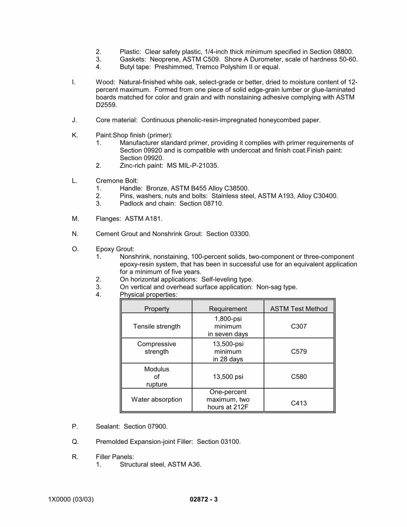
1X0000 (03/03) 02872 - 3
2. Plastic: Clear safety plastic, 1/4-inch thick minimum specified in Section 08800.3. Gaskets: Neoprene, ASTM C509. Shore A Durometer, scale of hardness 50-60.4. Butyl tape: Preshimmed, Tremco Polyshim II or equal.
I. Wood: Natural-finished white oak, select-grade or better, dried to moisture content of 12-percent maximum. Formed from one piece of solid edge-grain lumber or glue-laminatedboards matched for color and grain and with nonstaining adhesive complying with ASTMD2559.
J. Core material: Continuous phenolic-resin-impregnated honeycombed paper.
K. Paint:Shop finish (primer):1. Manufacturer standard primer, providing it complies with primer requirements of
Section 09920 and is compatible with undercoat and finish coat.Finish paint: Section 09920.
2. Zinc-rich paint: MS MIL-P-21035.
L. Cremone Bolt:1. Handle: Bronze, ASTM B455 Alloy C38500.2. Pins, washers, nuts and bolts: Stainless steel, ASTM A193, Alloy C30400.3. Padlock and chain: Section 08710.
M. Flanges: ASTM A181.
N. Cement Grout and Nonshrink Grout: Section 03300.
O. Epoxy Grout: 1. Nonshrink, nonstaining, 100-percent solids, two-component or three-component
epoxy-resin system, that has been in successful use for an equivalent applicationfor a minimum of five years.
2. On horizontal applications: Self-leveling type.3. On vertical and overhead surface application: Non-sag type.4. Physical properties:
Property Requirement ASTM Test Method
Tensile strength1,800-psiminimum
in seven daysC307
Compressivestrength
13,500-psiminimumin 28 days
C579
Modulusof
rupture13,500 psi C580
Water absorptionOne-percent
maximum, twohours at 212F C413
P. Sealant: Section 07900.
Q. Premolded Expansion-joint Filler: Section 03100.
R. Filler Panels: 1. Structural steel, ASTM A36.
02872 - 4 1X0000 (03/03)
S. Galvanizing Repair Compound: 1. Stick form, melting point 600F to 650F, 2. GALVABAR or equal.
2.02 FABRICATION:
A. Fabricated as shown on approved shop drawings.
B. Hollow-metal panels. Fabricate in accordance with SDI 100, Grade III, model 2A, one ofthe following styles:1. Seamless hollow-steel construction.2. Seamless composite construction.
C. Cremone bolt: Fabricate and assemble as shown.
D. Fabricate and fasten metalwork to prevent distortion and overstressing from expansionand contraction of metal. Conceal fastenings wherever practicable.
E. Perform welding in accordance with AWS D1.1. Grind exposed welds smooth. Finishflush and grind smooth welds exposed after installation.
F. Align members to provide true planes and square openings for installation of glasspanels. Fabricate horizontal and vertical members square, level, plumb with respect toother members and true within a tolerance of plus-or-minus 1/8 inch. Cap mullions.
G. Fabricate woodwork to AWI Architectural Woodwork Quality Standards, Premium-Grade.
H. Pre-Assembly and final Installation: Insofar as practicable, preassemble and fit work ofthis section in shop to ensure proper field assembly. To the extent that work cannot beshop-assembled with permanent connections; pre-assemble, mark and disassemblebefore shipment.
I. Galvanizing: For installations exposed to weather and elsewhere where indicated, hot-dipgalvanize enclosures and gates after fabrication and prior to finishing. Galvanize inlargest assembled units possible.1. Use hot-dip galvanizing process in accordance with ASTM A123, ASTM A153
and ASTM A384 as applicable.2. Clean and phosphatize surface as needed for priming.3. Prior to priming, treat welds and cut edges with a galvanizing repair compound at
a rate of two ounces per square foot, and prepare for priming.
J. Swing Gates1. Fabricate to operate smoothly with minimum applied pressure.2. Detail and construct assembles to permit replacement of components that wear
without disassembling entire gate.
K. Miscellaneous Components:1. Fabricate metal items indicated on the drawings from materials shown or, if not
otherwise described, from galvanized steel wherever exposed to the weather or incontact with concrete or masonry.
2. Make miscellaneous items to the size and configuration indicated, welded orbolted at joints to develop full strength equal to a continuous member, and inevery way complete for the intended purpose and finished in appearance.
1X0000 (03/03) 02872 - 5
2.03 SHOP PAINTING:A. Shop paint (prime) before shipment. Work primer well into joints. Do not prime surfaces
to be field-welded.
B. Ensure that galvanized surfaces are phosphatized before priming.
C. Thoroughly clean bare steel as recommended by primer manufacturer and in accordancewith SSPC SP11 and apply one shop primer coat; work well into joints. Do not primesurfaces to be field-welded.
D. On surfaces not accessible for field painting after erection, apply two coats of primer inshop.
E. Finish Paint: Silicone-alkyd, two coats over primer; color to be determined. See Section09920.
PART 3 - EXECUTION
3.01 PREPARATION:
A. Verify dimensions before proceeding. Measure structure to ensure accurate fit to otherconstruction, including wall-to-wall dimensions, floor-to-ceiling dimensions and thosecontrolled by other trades.
B. Remove foreign substances from surfaces to receive work described in this section.
C. Protect surrounding surfaces from damage while performing the work of this section.
3.02 INSTALLATION:
A. General:1. Coordinate work of this section with work of other trades.2. Fit work to adjoining construction as shown on Contract Drawings and approved
shop drawings.3. Install work plumb and true, properly align, and securely fasten as shown on
Contract Drawings and approved shop drawings.4. Firmly anchor mullion of each station-platform shelter to withstand inward or
outward wind pressure of 25 psf.5. Touch-up prime coat to cover field welds and damaged areas.6. Install glass and glazing material per specifications in Section 08800.7. Install cremone bolt and adjust operation as approved.
B. Coat field welds and repair damage to zinc-coated surfaces in accordance with ASTMA780 and as follows:1. Wire-brush areas to be coated to bright metal.2. Apply galvanizing repair compound at rate of two ounces per square foot and
prepare for priming.
C. Epoxy Grouting:1. Remove contaminants from surfaces receiving and coming into contact with the
grout. Remove surface contaminants such as curing compounds from holes thatreceive grout. Ensure that surfaces to receive grout are dry at the time ofgrouting.
2. Prime surfaces in accordance with grout manufacturer's recommendations unlessmanufacturer recommends against priming.
02872 - 6 1X0000 (03/03)
3. Mix and place epoxy grout for locations shown or specified as recommended bygrout manufacturer. Level exposed surfaces of grout joints with adjacentsurfaces. Grind rough or raised projections smooth and flush with adjacentsurfaces.
D. Painting and Repairing Coated Surfaces:1. Before enclosing construction, paint items that will be concealed in finished work.2. Where shop primer coat is abraded or burned by welding, clean, apply
galvanizing repair compound and touch-up. Touch-up primed surfaces with samematerial as original coating.
3. See Section 09920 for field painting.
3.03 CLEAN-UP:
A. Remove from the site rubbish and debris caused by this work.
B. Leave areas surrounding the work in broom-clean condition.
END OF SECTION
02890-11X0000 (03/03)
SECTION 02890
MARKERS
PART 1 - GENERAL
1.01 DESCRIPTION:
A. This section specifies providing markers.
B. Related Work Specified Elsewhere:1. Concrete reinforcement: Section 03200.2. Cast-in-place concrete: Section 03300.3. Precast Structural Concrete: Section 03400.
1.02 SUBMITTALS:
A. Submit the following for approval in accordance with the General Requirements and with theadditional requirements as specified for each:1. Product Data:
a. Manufacturer’s construction details showing materials, dimensions andprofiles for each individual component.
2. Shop Drawings:a. Plans, elevations and sections detailing fabrication and erection. Show
anchors, reinforcements, accessories, layout, installation details, colors andfinish treatments.
b. Message list including wording and lettering layout. Include full-size detailsof special graphics.
c. Setting drawings, templates and directions for installation of anchors to beinstalled as work in other sections.
1.03 QUALITY ASSURANCE:
A. Codes, Regulations, Reference Standards and Specifications.1. Comply with codes and regulations of the jurisdictional authorities.2. FS: QQ-B-654, WW-T-791.3. ASTM: B36, B135
B. Survey Certification:1. All Right-Of-Way markers shall be set by a surveyor registered in the area where the
work is to be performed.2. The following certification statement or a similar statement is required and shall be
placed on all approved Mylar sepia as-built Right-of-Way drawings:
"I hereby certify to the best of my knowledge that the Right-Of-Way markers shownon this as-built drawing have been set in accordance with the coordinate informationprovided by WMATA as shown on the Contract Documents."
__________________________________ (seal)Registered Surveyor in the State of Maryland *1
__________________________________ (seal)Registered Surveyor in the Commonwealth of Virginia *1
__________________________________ (seal)Registered Surveyor in the District of Columbia *1
02890-2 1X0000 (03/03)
PART 2 - PRODUCTS
2.01 MATERIALS:
A. Precast Concrete: Section 03400.
B. Concrete: Section 03300, Class 3500, air-entrained.
C. Concrete Reinforcement: Section 03200.
D. Bronze Discs:1. 3 ½ inch diameter domed survey marker forged from sold unleaded bronze in
accordance with ASTM B98-98 with a classic 3 inch long and 5/8 inch diameter split-style tapered stem designed for use in concrete or rock (the Corp of Engineers Type1 disc). Like or equivalent to the Berstsen C-1 Bronze 3 ½ inch domed marker#C35DB.
2. Refer to Standard Drawings ST-C-3 and ST-C-19 for additional details on bronzediscs and installation.
E. Epoxy Hilti
2.02 FABRICATION AND MANUFACTURE:
A. Markers and Monuments:1. Legend:
a. Apply legend shown for various markers and monuments using charactersof size and type shown. Clearly indicate use.
2. Bronze disc markers:a. Bronze discs as specified with imprinted or stamped legend.
3. Precast-concrete markers and monuments:a. Four inches square by length shown, with 1/2-inch chamfered edges.b. Precast concrete.c. One 29-inch long, No. 4 steel-reinforcing bar centered in casting.d. With lettering, when shown, incised v-shaped, 1/4-inch wide and 3/16-inch
in depth.
PART 3 - EXECUTION
3.01 BRONZE DISCS FOR MARKERS AND MONUMENTS:
A. Except as shown, form discs into convex shape 3/16 inch in depth with edges free from burrsand blemishes.
B. Press legend into the upper surface of disc so that surface is not raised. Ensure that legendconforms to that shown for markers and monuments.
C. Do not place letters closer than 1/8 inch to outer rim of marker. Letters in outer ring oflegend, 1/2-inch high; medium-sized letters, 7/32-inch high. Place letters along radius ofdisc. Imprint legend symmetrically about center of disc.
D. When bronze-disc markers are set in concrete pavements and roadways, set stem in drilledhole and secure with approved epoxy cement, like or equivalent to Hilti HIT Hy 150.
E. At other locations, set bronze-disc markers into tops of markers and monuments asspecified; set markers and monuments in ground at locations shown.
02890-31X0000 (03/03)
*1. Enter jurisdictions as applicable for the project locations.
3.02 PRECAST-CONCRETE MARKERS AND MONUMENTS:
A. Install precast-concrete markers and monuments at locations and to elevations shown or asdirected.
B. Set markers and monuments as shown. Compact bottom of excavation to preventsettlement.
END OF SECTION
SEE ENDNOTES BELOW. THEY ARE AN ESSENTIAL PART OF THIS SECTION UNTIL EDITED BYSECTION DESIGNER.
ENDNOTES:
10000 (03/03) 02920 - 1
SECTION 02920
TOPSOIL, SEEDING AND SODDING
PART 1 - GENERAL
1.01 DESCRIPTION:
A. This section specifies providing and maintaining seeding and sodding, including grass,crownvetch and lespedeza.
B. Related Work Specified Elsewhere.1. Site grading: Section 02320.2. Removal and restoration of existing landscaping: Section 02205.3. Landscaping: Section 02930.
C. Definitions:1. UMPC: University of Maryland, College Park2. Numerical fertilizer analysis: Three-digit number indicates nitrogen, phosphoric acid
and potash percentages by weight. Thus, 3-25-25 means three-percent nitrogen,25-percent phosphoric acid and 25-percent potash by weight.
1.02 QUALITY ASSURANCE:
A. Codes, Regulations, Reference Standards and Specifications: Keep always available at thework site a copy of each of the cited references.1. Codes and regulations of the jurisdictional authorities.2. USDA-SCS.3. UMPC: Current publication of Agronomy Mimeo #77 (Turfgrass Cultivar
Recommendations for Maryland).4. ASTM: C51.
B. Personnel Qualifications:1. Superintendent: Use a Superintendent with previous knowledge and verifiable
experience in supervising seeding and sodding work of similar size and scope. Havethe Superintendent present whenever work is being performed and have theSuperintendent responsible for controlling the quality of work and inspectingcompleted work to ensure that Contract requirements are met. The Superintendentis the primary contact person with the Engineer regarding seeding and sodding work.
2. Workers: Have the work performed only by experienced workers, who throughrelated training and verifiable previous on-the-job experience, are familiar with thetechnical aspects of seeding and sodding, and with the materials and equipmentused for each operation. Have each worker abide by the code of ethics orprofessional conduct established by the Landscape Contractors Association MD-DC-VA.
1.03 SUBMITTALS:
A. Submit the following for approval in accordance with the General Requirements and with theadditional requirements as specified for each:1. Samples and Certification:
a. Submit in accordance with Table 02920-1 and as follows:1) Seed: Each seed bag bearing the following upon delivery:
a) Analysis tag.
02920 - 2 1X0000 (03/03)
b) Certification tag.c) Maryland or Virginia State tags where applicable.
2) Inoculant: Sample packet of inoculant, viable bacteria, true tolegume strain required and listing source.
3) Sod: Maryland or Virginia State-Certified, each delivery bearing aMaryland or Virginia certification tag and label as required by law.
4) Topsoil: Submit supplier's name and address and source of topsoil.Submit certified report of soil laboratory test results listing textures,pH, P and K nutrients, soluble salt, organic matter and mechanicalanalysis as to percentage of sand, silt and clay. Do not delivertopsoil to site until approved. Approval does not constitute finalacceptance.
5) Fertilizer: Labeled with manufacturer's name and address,guaranteed analysis, including nutrient and its derived source andlisting of potential acidity.
6) Limestone and acidifying agent: Labeled with manufacturer's nameand address, chemical analysis, oxide content and size gradationof each used.
7) Mulch and mulch binder: Labeled with manufacturer's name andaddress, material components, trademark, chemical analysis,species, size, age and source.
8) Herbicide: Labeled with manufacturer's name and address andchemical analysis. Include in submittal the Material Safety DataSheet, with copies to the Engineer and Contractor’s Safety Officer.
b. Usable samples will be returned.2. Documentation:
a. Personnel qualifications: A list of the qualifications and experience of theworkers, and qualifications and experience of the Superintendent, asattested by knowledge and experience in supervising contracts of similarsize and scope in the past.
b. Soil tests for crownvetch and lespedeza areas: Submit certified report ofsoil tests made by a local state agricultural experiment station or agriculturallaboratory recommended by U.S. Department of Agriculture. Test for pH,P and K nutrients, soluble salt, organic matter and mechanical analysis asto percentage of sand, silt and clay; and include recommended quantitiesof soil amendments to be added to produce the target pH value and toproduce optimal growing conditions for the target crop.
c. Furnish one test for each 500 square feet of each crownvetch andlespedeza planting area, and not less than one test for each area.
d. Equipment list: A list of the equipment anticipated for use, including themake and model, year manufactured.
1.04 PRODUCT INSPECTION, DELIVERY, STORAGE AND HANDLING:
A. General: Materials and supplies are subject to inspection and sampling for testing. Allow noseed, sod, fertilizer, straw or other agronomic materials or supplies on site other than thosefor the project
B. Seed: Deliver with labels and tags.
C. Inoculants: Store inoculant containers below 70F until used. Keep containers sealed untilcontents are used in their entirety. Use inoculants before expiration date shown on packet.Using inoculants exposed to temperatures of 70F or greater is prohibited.
10000 (03/03) 02920 - 3
D. Sod: Deliver sod with labels and tags.1. Deliver sod to job within 24 hours after being cut; place sod within 36 hours after
being cut.2. Prior to and after delivery during wet weather, allow sod to dry to the extent that will
prevent tearing during handling and laying. During dry weather, water sod to ensureits vitality and prevent dropping of the soil in handling.
E. Topsoil: During hauling operations, keep walkway and roadway surfaces clean. Promptlyremove fallen material.
1.05 JOB CONDITIONS:
A. Conduct seeding and sodding only under favorable seasonal conditions throughout the periodof the Contract as determined by the Engineer. Install no work during adverse weather orduring periods when soil conditions are unfavorable as determined by the Engineer. Do notplant or lay sod during freezing weather, when planting area is muddy or frozen, nor whensod is frozen.
B. Protection: During progress of operations, protect walls, walks, curbs, benches, establishedlawn areas, plant material, and other site improvements by adequate means acceptable tothe Engineer.1. Weight Restrictions: Do not overload entrance paving, sidewalks and curbs. 2. Pollution: Take necessary and adequate measures to prevent soil erosion, air
pollution and water pollution by the materials and equipment used duringconstruction.
3. Repairs: If damage by the Contractor should occur, it is the Contractor'sresponsibility to repair or replace per the Engineer's direction, as acceptable toconcerned parties, and at no additional cost to the Authority. Perform work so thatdamaged areas make smooth, satisfactory, and imperceptible transitions to existingadjacent work. Use materials and methods conforming to current standards for thearea damaged, matching adjacent materials in appearance, and meeting approvalof jurisdictional authorities and the Engineer.
C. If, at any time, the Engineer determines that work is unsatisfactory or being conducted in anunsafe manner, immediately cease such work activities upon notification.
PART 2 - PRODUCTS
2.01 MATERIALS:
A. Seed: Free of quack grass, timothy, bentgrass, clover, dock, annual bluegrass, cheat, chess,chickweed, crabgrass, plantain, black medic and, except where specified in Table 02920-2,Canada Bluegrass. Kentucky Bluegrass and red fescue free of tall fescue.1. Grass Seed: Dated material from last available crop, with date of test not more than
nine months before date of sowing; listed as Proven Cultivars in the latest AgronomyMimeo #77 (Turfgrass Cultivar Recommendations for Maryland), published byUMPC; and as specified in Table 02920-2 below.
2. Crownvetch Seed: Dated material from last available crop, with date of test notmore than nine months before date of sowing. Germination portion consisting ofminimum 35-percent normal sprouts, maximum 35-percent hard seed and asspecified in Table 02920-4.
3. Appalow Sericea Lespedeza Seed: Germination portion consisting of minimum 35-percent normal sprouts, maximum 35-percent hard seed and as specified in Table02920-5.
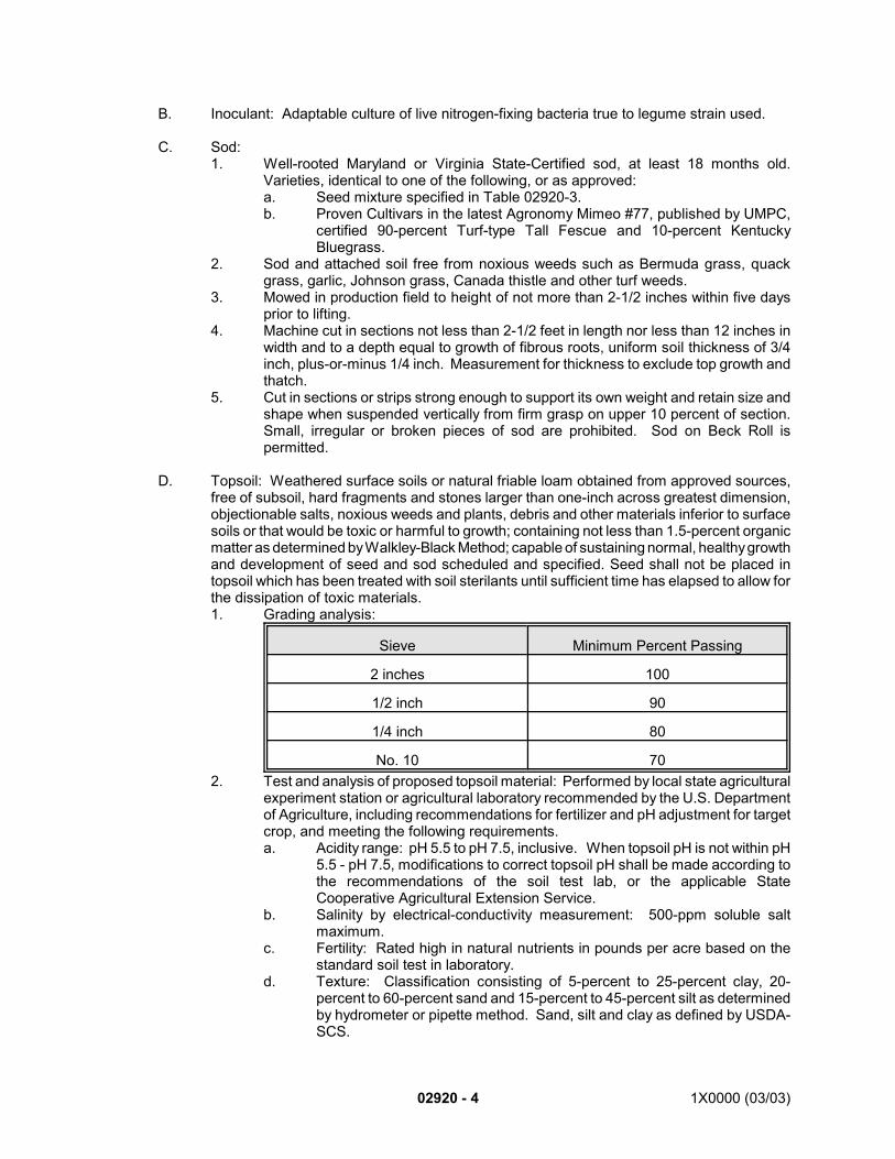
02920 - 4 1X0000 (03/03)
B. Inoculant: Adaptable culture of live nitrogen-fixing bacteria true to legume strain used.
C. Sod:1. Well-rooted Maryland or Virginia State-Certified sod, at least 18 months old.
Varieties, identical to one of the following, or as approved:a. Seed mixture specified in Table 02920-3.b. Proven Cultivars in the latest Agronomy Mimeo #77, published by UMPC,
certified 90-percent Turf-type Tall Fescue and 10-percent KentuckyBluegrass.
2. Sod and attached soil free from noxious weeds such as Bermuda grass, quackgrass, garlic, Johnson grass, Canada thistle and other turf weeds.
3. Mowed in production field to height of not more than 2-1/2 inches within five daysprior to lifting.
4. Machine cut in sections not less than 2-1/2 feet in length nor less than 12 inches inwidth and to a depth equal to growth of fibrous roots, uniform soil thickness of 3/4inch, plus-or-minus 1/4 inch. Measurement for thickness to exclude top growth andthatch.
5. Cut in sections or strips strong enough to support its own weight and retain size andshape when suspended vertically from firm grasp on upper 10 percent of section.Small, irregular or broken pieces of sod are prohibited. Sod on Beck Roll ispermitted.
D. Topsoil: Weathered surface soils or natural friable loam obtained from approved sources,free of subsoil, hard fragments and stones larger than one-inch across greatest dimension,objectionable salts, noxious weeds and plants, debris and other materials inferior to surfacesoils or that would be toxic or harmful to growth; containing not less than 1.5-percent organicmatter as determined by Walkley-Black Method; capable of sustaining normal, healthy growthand development of seed and sod scheduled and specified. Seed shall not be placed intopsoil which has been treated with soil sterilants until sufficient time has elapsed to allow forthe dissipation of toxic materials.1. Grading analysis:
Sieve Minimum Percent Passing
2 inches 100
1/2 inch 90
1/4 inch 80
No. 10 702. Test and analysis of proposed topsoil material: Performed by local state agricultural
experiment station or agricultural laboratory recommended by the U.S. Departmentof Agriculture, including recommendations for fertilizer and pH adjustment for targetcrop, and meeting the following requirements.a. Acidity range: pH 5.5 to pH 7.5, inclusive. When topsoil pH is not within pH
5.5 - pH 7.5, modifications to correct topsoil pH shall be made according tothe recommendations of the soil test lab, or the applicable StateCooperative Agricultural Extension Service.
b. Salinity by electrical-conductivity measurement: 500-ppm soluble saltmaximum.
c. Fertility: Rated high in natural nutrients in pounds per acre based on thestandard soil test in laboratory.
d. Texture: Classification consisting of 5-percent to 25-percent clay, 20-percent to 60-percent sand and 15-percent to 45-percent silt as determinedby hydrometer or pipette method. Sand, silt and clay as defined by USDA-SCS.
10000 (03/03) 02920 - 5
E. Fertilizer:1. For grass seeded and sodded areas: Commercial fertilizer of standard quality,
recommended by approved soil test report; 10-22-22.2. For crownvetch seeded areas: Use both of the following:
a. Commercial fertilizer of standard quality; 0-20-20 or 3-25-25.b. Blue Chip Nitroform, slow-release nitrogen, granular form, of standard
quality; 38-0-0.3. For appalow-sericea-lespedeza seeded areas: Commercial fertilizer of standard
quality, recommended by approved soil test report; 10-22-22.
F. Limestone: ASTM C51, Dolomitic, Agricultural Grade.1. Capable of neutralizing soil acidity and containing not less than 85 percent calcium
and magnesium carbonates2. Sieve analysis: 95-percent passing No. Eight sieve and 40-percent passing a No.
100 sieve. For hydroseeding, use pulverized limestone.3. Containers labeled to show chemicals.
G. Acidifying Agent: As approved per soil analysis recommendations and seeding method.
H. Mulch:1. Wood-cellulose fiber: Containing no growth or germination-inhibiting factors and
dyed green.a. Properties:
1) Fiber length: Approximately 3/8 inch.2) Diameter: Approximately 1/32 inch.3) Acidity range: pH 4.0 to 8.5, inclusive.4) Ash content: 1.6-percent maximum.5) Water-holding capacity: 90-percent minimum.
b. Packaging: Furnish fibers air-dry in packages not exceeding 50 poundsgross, with net weight shown on package.
c. Source: Conwed Hydro Mulch by Conwed Corp., St. Paul, MN 55101 orequal.
2. Straw: Wheat, barley, oat or rye straw, threshed, air-dried and free from Canadathistle, dock, Johnson grass and other foreign matter.
3. Mulch blanket: Knitted construction of biodegradable yarn with uniform openings,Gulf States Paper Corporation, Tuscaloosa, AL 35401 or equal.a. 150-foot lengths or greater.b. U-shaped staples: As standard with mulch-blanket manufacturer.
I. Mulch Binders: Non-asphaltic only.1. Synthetic binder for use with the following:
a. Wood-cellulose fiber: Terra Tack 1 by Grass Growers, Plainfield, NJ 07061;Soil-Gard by Alco Chemical Company, Philadelphia, PA 1913, or equal.
b. Straw: Terra Tack 1 by Grass Growers, Plainfield, NJ 07061 or equal.2. Biodegradable netting for use with straw: Conwed Erosion Control Netting by
Conwed Corporation, St. Paul, MN 55101 or equal.
J. Herbicides:1. Broadleaf weed control: Trimec by P.B.I. Gordon Corporation, Kansas City, KS
66118 or equal.2. Pre-emergent crabgrass control: Balan by Elanco Products Company, Division of
Eli Lilly Corporation, Indianapolis, IN 46206 or equal.3. Post-emergent crabgrass control: A.M.A., D.S.M.A., M.A.M.A. or Calcium Methyl
Arsenate by W.A. Cleary Company, Somerset, NJ 08873 or equal.4. Perennial bunch-grass control: Round-up by Monsanto Agricultural Products
Company, Wilmington, DE 19810 or equal.
02920 - 6 1X0000 (03/03)
K. Stakes (for pegging sod): Wood or other biodegradable stakes suitable for the purpose,measuring 1/2-inch by one-inch by 12 inches.
L. Water: Potable.
2.02 SEED MIXTURES:
A. Grass Seed: Tables 02920-2 and 02920-3.
B. Crownvetch Seed: Table 02920-4.
C. Lespedeza Seed: Table 02920-5.
D. Hydroseeding Crownvetch and Lespedeza Seed: Tables 02920-6 and 02920-7.
2.03 EQUIPMENT:
A. Dry-Type Seeder: Brillion seeder, drill seeder or other approved mechanical seeder.
B. Spraying Equipment for Hydroseeding: Use water tank equipped with liquid-level gaugecalibrated in increments not larger than 50 gallons over entire range of tank capacity withgauge visible to nozzle operator. Use tank equipped with agitation system capable ofmaintaining solids in complete suspension until used.
PART 3 - EXECUTION
3.01 PLACING TOPSOIL:
A. After completion of construction work in the area, prepare surface of subsoil. Finish to linesshown and parallel to proposed finished grade, as approved. Remove rocks and otherforeign materials 1-1/2 inches or greater in any dimension. Immediately prior to covering withtopsoil, loosen prepared subsoil surface to a minimum depth of four inches. Leave nodepressions.
B. Place and spread topsoil over areas to be seeded and sodded except areas to receivecrownvetch or lespedeza (unless Contract Drawings require 2:1 or greater slopes to besodded or seeded), to depth which will produce four-inch depth after natural settlement andwill conform to finish lines, grades and elevations.
C. When placing topsoil on slopes, work topsoil into subsoil to minimum depth of four inches toeliminate slip-plane between the two materials. Leave topsoil at surface to ensuregermination of seed.
D. After spreading topsoil, rake up and remove large stiff clods, hard lumps, large rocks, roots,stumps, litter and other foreign matter.
E. Maintain specified depth of topsoil from time placed until specified seed or sod is established.
F. If soil or weather conditions are unsuitable, cease topsoil operations. Resume topsoiloperations when proper conditions prevail.
3.02 SEEDING GRASS:
10000 (03/03) 02920 - 7
A. Dry Seeding: After placing topsoil, proceed as follows:1. Seed bed preparation:
a. pH adjustment: Adjust topsoil pH to raise it by applying limestone orapproved acidifying agent or elemental sulfur to lower the topsoil pH at per-acre rate recommended by approved soil test report so as to obtain a 6.5pH. Apply separately prior to fertilizing and seeding operations. Work intothe top three inches of soil.
b. Fertilizing: After acidity adjustment and within 24 hours before seeding,apply fertilizer at per-acre rate recommended by approved soil test report.Use machine spreader and lightly drag or rake fertilizer into top 1/4 inch ofsoil.
2. Seeding: Clean seeders as approved prior to applying seed. Apply seed mixturedirectly after fertilizing.a. Sow specified grass seed mixture from March 1 to April 30 and from August
15 to October 15. Extend or reduce specified periods as approved and asrequired by weather and soil conditions.
b. Sow at minimum rate as specified in Table 02920-3.c. Work seed in to depth of 1/4-inch maximum.d. Finish as follows:
1) Lawn areas with slopes up to 3:1: Raked surface.2) Roadside areas with slopes up to 3:1: Scarified surface.3) Slopes over 3:1: Leave surface in irregular condition with ridges
running parallel to contour of slope to prevent erosion.3. Rolling: Directly after seeding, roll lawn areas with slopes up to 3:1 using approved
lawn roller, weighing 40 to 60 pounds per foot of width, unless interveningprecipitation would cause such rolling to be detrimental.
B. Hydroseeding: After placing topsoil, proceed as follows:1. Seed bed preparation:
a. Clean hydroseeders as approved prior to coming on site.b. pH adjustment: Adjust soil pH by either applying limestone or approved
acidifying agent or elemental sulfur at per-acre rate recommended byapproved soil test report so as to obtain a 6.5 pH. Apply separately prior tofertilizing and seeding operations.1) Use only pulverized limestone to raise soil pH.2) Apply not more than 300 pounds of limestone for each 100 gallons
of water.3) After applied limestone mixture has dried, work into the top three
inches of soil.c. Apply elemental sulfur as recommended, and incorporate into top three
inches of soil.d. After pH adjustment, again grade and dress seed beds for lawn areas to
raked surface.2. Fertilizing and seeding: After seed bed preparation, apply fertilizer-seed mixture.
a. Apply fertilizer at per-acre rate recommended by approved soil test report.b. Apply seed at same rates and times specified for dry seeding.Mix seed and
fertilizer together in proportions to meet required application rates.c. If mulching with wood-cellulose fiber on areas with slopes up to 3:1, add
mulch to seed and fertilizer mixture.3. Application method:
a. Apply mixtures by means of high-pressure spray directed upward into air sothat mixtures fall to ground in uniform spray. Do not direct nozzle of hand-held hose toward ground in manner that would produce erosion or runoff.
b. Make uniform applications at required rate, with two passes at 90 degreesto each other, to ensure uniformity and prevent misses.
c. Agitate mixtures constantly from time mixed until application to seed bed.
02920 - 8 1X0000 (03/03)
d. Use mixtures within eight hours after mixing.
3.03 SEEDING CROWNVETCH:
A. Seed Bed Preparation: After construction work in the area has been completed, proceed asfollows:1. Grading: Rough grade to remove large stones and roots. Remove or break up
clods greater than one-foot diameter. Chisel surface to depth of four to six inches.When preparing slopes, chisel parallel to contour of slope.
2. pH adjustment: Adjust soil pH by applying limestone or approved acidifying agentor elemental sulfur at per-acre rate in Table 02920-6, except as recommended byapproved soil test report so as to obtain a 6.5 pH. Apply separately prior to fertilizingand seeding operations.a. Apply 2/3 of limestone when seed bed is prepared. Work this into the top
six inches of soil.b. Apply remaining 1/3 of limestone with seed mixture.
3. Fertilizing: After acidity adjustment, apply fertilizer at per-acre rate in Table 02920-6,except as recommended by approved soil test report.
4. Hydraulic overseeding: For overseeding existing vegetation, cut existing vegetationto height of three inches and remove resultant refuse prior to overseeding.
B. Seed Preparation:1. Inoculate crownvetch seed on day it is used.2. Reinoculate seeds not sown within 24 hours following inoculation.
C. Hydroseeding: Clean hydroseeders as approved prior to coming on site.1. From March 1 to October 15, sow specified crownvetch seed mixture (Table
02920-4) at a rate of 100 pounds per acre.2. From June 1 to August 15 sow specified crownvetch seed mixture (Table 02920-4)
at a rate of 100 pounds per acre, except add an additional three-percent by weightof Loehmans Weeping Lovegrass.
3. Extend or reduce specified periods as approved and as required by weather and soilconditions.
4. Bare areas: Perform application-sequence Stages I and II, specified below.5. Existing vegetation areas (hydraulic overseeding): Perform only application-
sequence Stage I, specified below. Obtain the Engineer’s on-site approval onwhether to use nozzle or hose for hydraulic overseeding.
6. Application method:a. Apply mixtures by means of high-pressure spray directed upward into air so
that mixtures fall to ground in uniform spray. Do not direct nozzle of hand-held hose toward ground in manner that would produce erosion or runoff.
b. Make uniform applications at required rate, with two passes at 90 degreesto each other, to ensure uniformity and prevent misses.
c. Agitate mixtures constantly from time mixed until application to seed bed.Use mixtures within eight hours after mixing.
d. Use inoculated crownvetch in slurry with fertilizers within one hour aftermixing. Use fresh crownvetch seed and reinoculate seed whenever thisrequirement cannot be met.
7. Application sequence:a. Stage I, Table 02920-5: Load materials into water-filled tanks in proportion
to tank size; agitate until smooth slurry is formed. Spray on seed bed atrates specified. Follow within two hours with Stage II.
b. Stage II, Table 02920-6: Mulch area within two hours after completingStage I. Use straw mulch for slopes up to 2:1. Use mulch blanket forslopes greater than 2:1. Do not use wood-cellulose fiber.
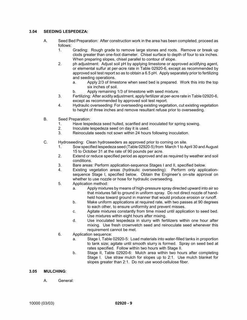
10000 (03/03) 02920 - 9
3.04 SEEDING LESPEDEZA:
A. Seed Bed Preparation: After construction work in the area has been completed, proceed asfollows:1. Grading: Rough grade to remove large stones and roots. Remove or break up
clods greater than one-foot diameter. Chisel surface to depth of four to six inches.When preparing slopes, chisel parallel to contour of slope.
2. ph adjustment: Adjust soil pH by applying limestone or approved acidifying agent,or elemental sulfur at per-acre rate in Table 02920-6, except as recommended byapproved soil test report so as to obtain a 6.5 pH. Apply separately prior to fertilizingand seeding operations.a. Apply 2/3 of limestone when seed bed is prepared. Work this into the top
six inches of soil.b. Apply remaining 1/3 of limestone with seed mixture.
3. Fertilizing: After acidity adjustment, apply fertilizer at per-acre rate in Table 02920-6,except as recommended by approved soil test report.
4. Hydraulic overseeding: For overseeding existing vegetation, cut existing vegetationto height of three inches and remove resultant refuse prior to overseeding.
B. Seed Preparation:1. Have lespedeza seed hulled, scarified and inoculated for spring sowing.2. Inoculate lespedeza seed on day it is used.3. Reinoculate seeds not sown within 24 hours following inoculation.
C. Hydroseeding: Clean hydroseeders as approved prior to coming on site.1. Sow specified lespedeza seed (Table 02920-5) from March 1 to April 30 and August
15 to October 31 at the rate of 90 pounds per acre.2. Extend or reduce specified period as approved and as required by weather and soil
conditions.3. Bare areas: Perform application-sequence Stages I and II, specified below.4. Existing vegetation areas (hydraulic overseeding): Perform only application-
sequence Stage I, specified below. Obtain the Engineer’s on-site approval onwhether to use nozzle or hose for hydraulic overseeding.
5. Application method:a. Apply mixtures by means of high-pressure spray directed upward into air so
that mixtures fall to ground in uniform spray. Do not direct nozzle of hand-held hose toward ground in manner that would produce erosion or runoff.
b. Make uniform applications at required rate, with two passes at 90 degreesto each other, to ensure uniformity and prevent misses.
c. Agitate mixtures constantly from time mixed until application to seed bed.Use mixtures within eight hours after mixing.
d. Use inoculated lespedeza in slurry with fertilizers within one hour aftermixing. Use fresh crownvetch seed and reinoculate seed whenever thisrequirement cannot be met.
6. Application sequence:a. Stage I, Table 02920-5: Load materials into water-filled tanks in proportion
to tank size; agitate until smooth slurry is formed. Spray on seed bed atrates specified. Follow within two hours with Stage II.
b. Stage II, Table 02920-6: Mulch area within two hours after completingStage I. Use straw mulch for slopes up to 2:1. Use mulch blanket forslopes greater than 2:1. Do not use wood-cellulose fiber.
3.05 MULCHING:
A. General:
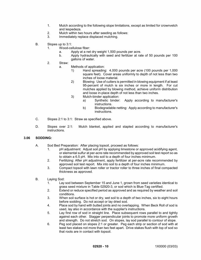
02920 - 10 1X0000 (03/03)
1. Mulch according to the following slope limitations, except as limited for crownvetchand lespedeza.
2. Mulch within two hours after seeding as follows:3. Immediately replace displaced mulching.
B. Slopes up to 3:1:1. Wood-cellulose fiber:
a. Apply at a net dry weight 1,500 pounds per acre.b. Apply hydraulically with seed and fertilizer at rate of 50 pounds per 100
gallons of water.2. Straw:
a. Methods of application:1) Hand spreading: 4,000 pounds per acre (100 pounds per 1,000
square feet). Cover areas uniformly to depth of not less than twoinches of loose material.
2) Blowing: Use of cutters is permitted in blowing equipment if at least95-percent of mulch is six inches or more in length. For cutmulches applied by blowing method, achieve uniform distributionand loose in-place depth of not less than two inches.
3) Mulch-binder application:a) Synthetic binder: Apply according to manufacturer's
instructions.b) Biodegradable netting: Apply according to manufacturer's
instructions.
C. Slopes 2:1 to 3:1: Straw as specified above.
D. Slopes over 2:1: Mulch blanket, applied and stapled according to manufacturer'sinstructions.
3.06 SODDING:
A. Sod Bed Preparation: After placing topsoil, proceed as follows:1. pH adjustment: Adjust soil pH by applying limestone or approved acidifying agent,
or elemental sulfur at per-acre rate recommended by approved soil test report so asto obtain a 6.5 pH. Mix into soil to a depth of four inches minimum.
2. Fertilizing: After pH adjustment, apply fertilizer at per-acre rate recommended byapproved soil test report. Mix into soil to a depth of four inches minimum.
3. Compact topsoil with lawn roller or tractor roller to three inches of final compactedthickness as approved.
B. Laying Sod:1. Lay sod between September 15 and June 1, grown from seed varieties identical to
grass seed mixture in Table 02920-3, or sod which is Blue-Tag certified.2. Extend or reduce specified period as approved and as required by weather and soil
conditions.3. When soil surface is hot or dry, wet soil to a depth of two inches, six to eight hours
before sodding. Do not accept or lay dried sod.4. Place sod by hand with butted joints and no overlapping. When Beck Roll of sod is
used, lay also in accordance with the supplier's instructions.5. Lay first row of sod in straight line. Place subsequent rows parallel to and tightly
against each other. Stagger perpendicular joints to promote more uniform growthand strength. Do not stretch sod. On slopes, lay sod parallel to contour of slope.
6. Peg sod placed on slopes 2:1 or greater. Peg each strip or section of sod with atleast two stakes not more than two feet apart. Drive stakes flush with top of sod sothat roots are in contact with topsoil.
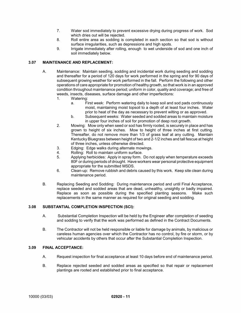
10000 (03/03) 02920 - 11
7. Water sod immediately to prevent excessive drying during progress of work. Sodwhich dries out will be rejected.
8. Roll entire area as sodding is completed in each section so that sod is withoutsurface irregularities, such as depressions and high spots.
9. Irrigate immediately after rolling, enough to wet underside of sod and one inch ofsoil immediately below.
3.07 MAINTENANCE AND REPLACEMENT:
A. Maintenance: Maintain seeding, sodding and incidental work during seeding and soddingand thereafter for a period of 120 days for work performed in the spring and for 90 days ofsubsequent growing weather for work performed in the fall. Perform the following and otheroperations of care appropriate for promotion of healthy growth, so that work is in an approvedcondition throughout maintenance period; uniform in color, quality and coverage; and free ofweeds, insects, diseases, surface damage and other imperfections:1. Watering:
a. First week: Perform watering daily to keep soil and sod pads continuouslymoist, maintaining moist topsoil to a depth of at least four inches. Waterprior to heat of the day as necessary to prevent wilting or as approved.
b. Subsequent weeks: Water seeded and sodded areas to maintain moisturein upper four inches of soil for promotion of deep root growth.
2. Mowing: Mow only when seed or sod has firmly rooted, is securely in place and hasgrown to height of six inches. Mow to height of three inches at first cutting.Thereafter, do not remove more than 1/3 of grass leaf at any cutting. MaintainKentucky Bluegrass between height of two and 2-1/2 inches and tall fescue at heightof three inches, unless otherwise directed.
3. Edging: Edge walks during alternate mowings.4. Rolling: Roll to maintain uniform surface.5. Applying herbicides: Apply in spray form. Do not apply when temperature exceeds
80F or during periods of drought. Have workers wear personal protective equipmentappropriate for the submitted MSDS.
6. Clean-up: Remove rubbish and debris caused by this work. Keep site clean duringmaintenance period.
B. Replacing Seeding and Sodding: During maintenance period and until Final Acceptance,replace seeded and sodded areas that are dead, unhealthy, unsightly or badly impaired.Replace as soon as possible during the specified planting seasons. Make suchreplacements in the same manner as required for original seeding and sodding.
3.08 SUBSTANTIAL COMPLETION INSPECTION (SCI):
A. Substantial Completion Inspection will be held by the Engineer after completion of seedingand sodding to verify that the work was performed as defined in the Contract Documents.
B. The Contractor will not be held responsible or liable for damage by animals, by malicious orcareless human agencies over which the Contractor has no control, by fire or storm, or byvehicular accidents by others that occur after the Substantial Completion Inspection.
3.09 FINAL ACCEPTANCE:
A. Request inspection for final acceptance at least 10 days before end of maintenance period.
B. Replace rejected seeded and sodded areas as specified so that repair or replacementplantings are rooted and established prior to final acceptance.
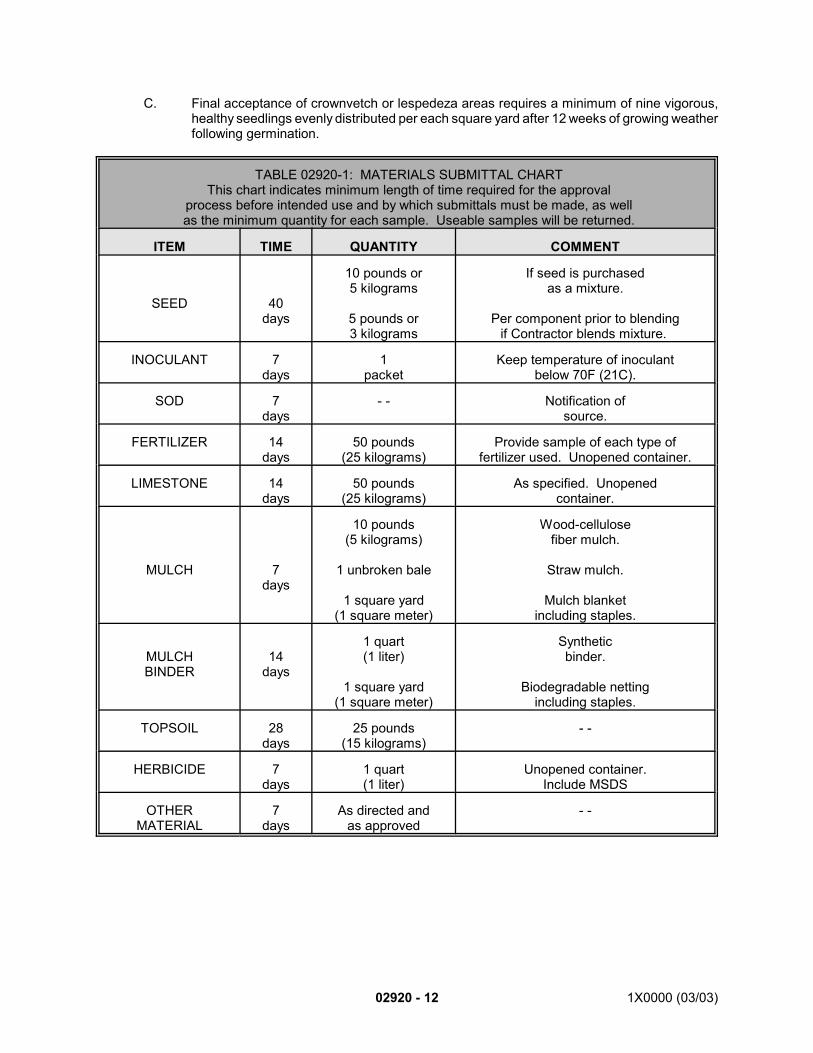
02920 - 12 1X0000 (03/03)
C. Final acceptance of crownvetch or lespedeza areas requires a minimum of nine vigorous,healthy seedlings evenly distributed per each square yard after 12 weeks of growing weatherfollowing germination.
TABLE 02920-1: MATERIALS SUBMITTAL CHARTThis chart indicates minimum length of time required for the approval
process before intended use and by which submittals must be made, as wellas the minimum quantity for each sample. Useable samples will be returned.
ITEM TIME QUANTITY COMMENT
SEED 40days
10 pounds or5 kilograms
5 pounds or3 kilograms
If seed is purchasedas a mixture.
Per component prior to blendingif Contractor blends mixture.
INOCULANT 7days
1packet
Keep temperature of inoculantbelow 70F (21C).
SOD 7days
- - Notification ofsource.
FERTILIZER 14days
50 pounds(25 kilograms)
Provide sample of each type offertilizer used. Unopened container.
LIMESTONE 14days
50 pounds(25 kilograms)
As specified. Unopenedcontainer.
MULCH 7days
10 pounds(5 kilograms)
1 unbroken bale
1 square yard(1 square meter)
Wood-cellulosefiber mulch.
Straw mulch.
Mulch blanketincluding staples.
MULCHBINDER
14days
1 quart(1 liter)
1 square yard(1 square meter)
Syntheticbinder.
Biodegradable nettingincluding staples.
TOPSOIL 28days
25 pounds(15 kilograms)
- -
HERBICIDE 7days
1 quart(1 liter)
Unopened container.Include MSDS
OTHERMATERIAL
7days
As directed andas approved
- -
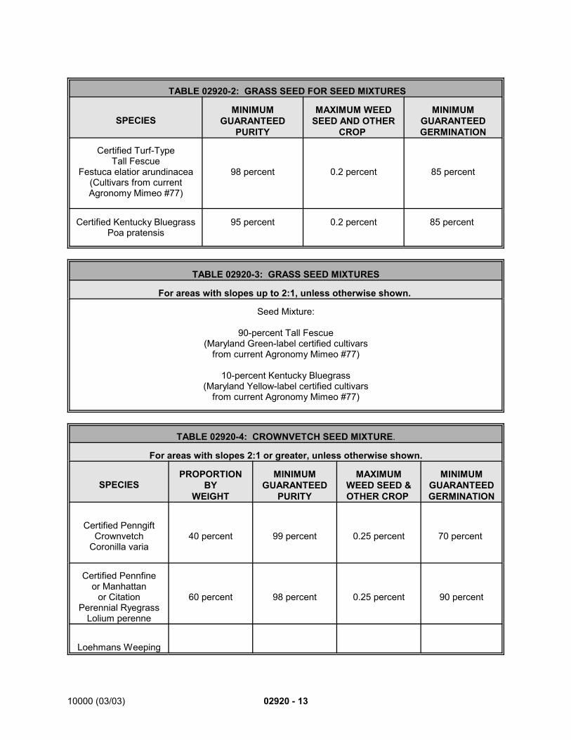
10000 (03/03) 02920 - 13
TABLE 02920-2: GRASS SEED FOR SEED MIXTURES
SPECIESMINIMUM
GUARANTEEDPURITY
MAXIMUM WEEDSEED AND OTHER
CROP
MINIMUMGUARANTEEDGERMINATION
Certified Turf-TypeTall Fescue
Festuca elatior arundinacea(Cultivars from currentAgronomy Mimeo #77)
98 percent 0.2 percent 85 percent
Certified Kentucky BluegrassPoa pratensis
95 percent 0.2 percent 85 percent
TABLE 02920-3: GRASS SEED MIXTURES
For areas with slopes up to 2:1, unless otherwise shown.
Seed Mixture:
90-percent Tall Fescue(Maryland Green-label certified cultivars
from current Agronomy Mimeo #77)
10-percent Kentucky Bluegrass(Maryland Yellow-label certified cultivars
from current Agronomy Mimeo #77)
TABLE 02920-4: CROWNVETCH SEED MIXTURE.
For areas with slopes 2:1 or greater, unless otherwise shown.
SPECIESPROPORTION
BYWEIGHT
MINIMUMGUARANTEED
PURITY
MAXIMUMWEED SEED &OTHER CROP
MINIMUMGUARANTEEDGERMINATION
Certified PenngiftCrownvetch
Coronilla varia40 percent 99 percent 0.25 percent 70 percent
Certified Pennfineor Manhattan
or CitationPerennial Ryegrass
Lolium perenne
60 percent 98 percent 0.25 percent 90 percent
Loehmans Weeping
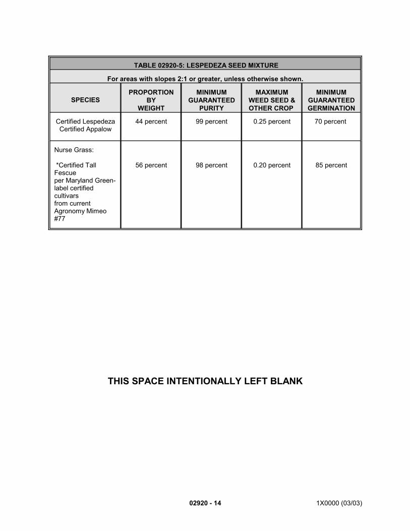
02920 - 14 1X0000 (03/03)
TABLE 02920-5: LESPEDEZA SEED MIXTURE
For areas with slopes 2:1 or greater, unless otherwise shown.
SPECIESPROPORTION
BYWEIGHT
MINIMUMGUARANTEED
PURITY
MAXIMUMWEED SEED &OTHER CROP
MINIMUMGUARANTEEDGERMINATION
Certified LespedezaCertified Appalow
44 percent 99 percent 0.25 percent 70 percent
Nurse Grass:
*Certified TallFescueper Maryland Green-label certifiedcultivarsfrom currentAgronomy Mimeo#77
56 percent 98 percent 0.20 percent 85 percent
THIS SPACE INTENTIONALLY LEFT BLANK
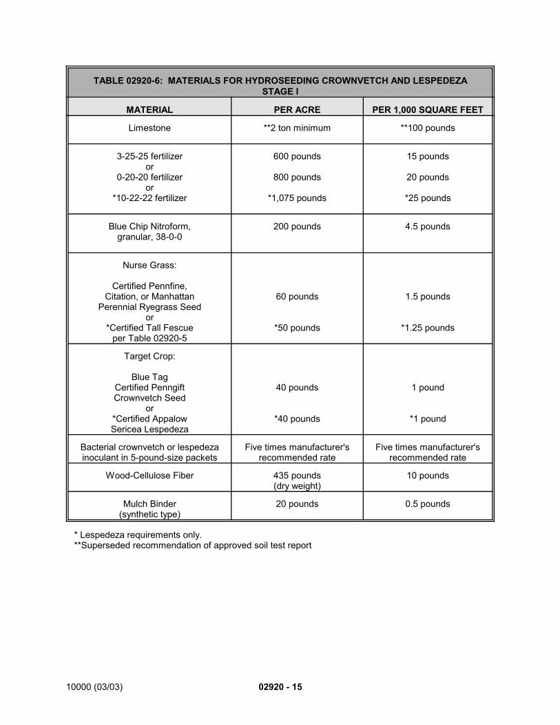
10000 (03/03) 02920 - 15
TABLE 02920-6: MATERIALS FOR HYDROSEEDING CROWNVETCH AND LESPEDEZASTAGE I
MATERIAL PER ACRE PER 1,000 SQUARE FEET
Limestone **2 ton minimum **100 pounds
3-25-25 fertilizeror
0-20-20 fertilizeror
*10-22-22 fertilizer
600 pounds
800 pounds
*1,075 pounds
15 pounds
20 pounds
*25 pounds
Blue Chip Nitroform,granular, 38-0-0
200 pounds 4.5 pounds
Nurse Grass:
Certified Pennfine,Citation, or Manhattan
Perennial Ryegrass Seedor
*Certified Tall Fescueper Table 02920-5
60 pounds
*50 pounds
1.5 pounds
*1.25 pounds
Target Crop:
Blue TagCertified PenngiftCrownvetch Seed
or*Certified AppalowSericea Lespedeza
40 pounds
*40 pounds
1 pound
*1 pound
Bacterial crownvetch or lespedezainoculant in 5-pound-size packets
Five times manufacturer'srecommended rate
Five times manufacturer'srecommended rate
Wood-Cellulose Fiber 435 pounds(dry weight)
10 pounds
Mulch Binder(synthetic type)
20 pounds 0.5 pounds
* Lespedeza requirements only.**Superseded recommendation of approved soil test report
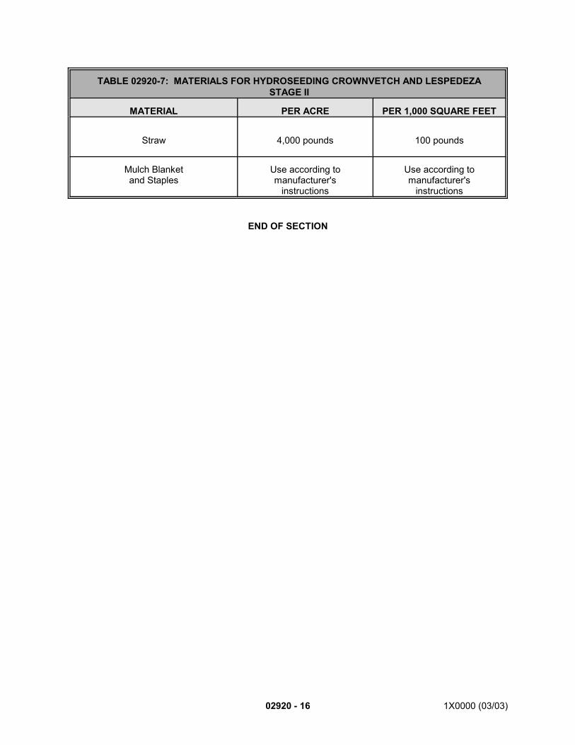
02920 - 16 1X0000 (03/03)
TABLE 02920-7: MATERIALS FOR HYDROSEEDING CROWNVETCH AND LESPEDEZASTAGE II
MATERIAL PER ACRE PER 1,000 SQUARE FEET
Straw 4,000 pounds 100 pounds
Mulch Blanketand Staples
Use according tomanufacturer's
instructions
Use according tomanufacturer's
instructions
END OF SECTION
1X0000 (08/01) 02930 - 1
SECTION 02930
LANDSCAPING
PART 1 - GENERAL
1.01 DESCRIPTION:
A. This section specifies providing and maintaining landscape plantings, edge plantings andrelated accessories. It also specifies existing tree pruning and removal requirements.
B. Related Work Specified Elsewhere:1. Site grading: Section 02320.2. Seeding and sodding: Section 02920.3. Removal and restoration of existing landscaping: Section 02205.4. Reforestation: Section 02933.
C. Definitions:1. Landscape Plantings (Outside Reforestation areas and in Median strips): Designed
planting of trees and shrubs within lawn or established areas, as shown. Landscapeplantings are indicated on the Drawings with a square symbol as shown on the keyin the Drawings.
2. Edge Plantings: Planting of trees and shrubs along edge of reforestation areas, asshown. Edge plantings are indicated on the Drawings with a triangular symbol asshown on the key in the Drawings.
3. Reforestation: Planting of trees and shrubs within designated reforestation areas.These reforestation areas are outside the limits of existing woodlands and wetlandsand of landscape and mow areas, as shown. Reforestation planting areas areindicated on the Drawings with small circles as shown on the key in the Drawings.
4. Plants or Plant Material: Vegetation, including trees, shrubs, ground cover, vines,and seasonal flowers.
5. Size: The factor controlled by dimensions representing caliper, height or spread.For standard quality a dimension is given for caliper, height or spread, whichever isa typical characteristic of the plant. For specimen quality, all dimensions may bespecified.
6. Condition: The factor controlled by vitality and ability to survive and thrive and becomparable with normal plants of the same species and variety in the vicinity, at thesame season of the year, free from physical damage or adverse condition that wouldprevent thriving, whether dormant or growing.
7. Foliage line: Maximum dimension measured from ground to lowest part of body ofplant.
8. Quality: Structure and form as evidenced by density and number of canes andbranches, compactness, symmetry and general development, without considerationof size or condition. a. Standard: The least acceptable quality, good average uniform growth,
absence of irregularities, typical characteristics of the species and variety,nursery-grown, well-formed, and uniformly branched, sound, healthy,vigorous and free of disease and insects, and having healthy,well-developed root systems, and having the minimum number of canesspecified or conforming to minimum quality index. Plant materials belowspecified standard will be considered unacceptable culls and are notacceptable.
02930 - 2 1X0000 (08/01)
b. Specimen: An exceptionally heavy, symmetrical, tightly knit plant, trainedor favored in its development and appearance so as to be Anunquestionably and outstandingly superior in form, of the designatedspecies or cultivar number of branches, compactness and symmetry.
9. Spread: Single dimension that represents the minimum acceptable width. Whererange is shown between two spread dimensions, the lesser is the minimumacceptable.
10. Root Protection Zone (Area): The root protection area is an area equal to a radiusof 1.5 feet for each inch of diameter at breast height (dbh) (i.e.; a 10-inch dbh treewill require protection 15 feet from the main trunk in every direction.
11. Diameter at Breast Height (DBH): The DBH is the trunk diameter measured at apoint 4.5 feet (Maryland State Standard) above the average ground level. If the trunkdivides into several smaller trunks at a point lower than 4.5 feet (Maryland StateStandard) from the ground, the tree size is the diameter measured at the highestpoint on the single trunk.a. If a tree falls between sizes as listed in the bid schedule, the tree is placed
in the next larger size. For example, a 17-1/2 inch diameter tree is placedin the 18-inch to 23-inch size.
12. Tracing: Careful cutting of bark along the line of sap flow to encourage woundclosure and to smoothly outline the wound area.
13. Girdling Roots: Surface roots whose circular growth around the base of a tree trunkor around other roots applies pressure to the bark thereby restricting the sap flow.
14. Stumps: Stumps include the base of the trunk and visible surface roots attached tothe trunk no more than three feet high, measured from the average ground level.Stump size is the diameter of the cut wood surface as measured across thenarrowest portion.
15. B&B: Balled and burlapped.16. NIC: Not in Contract.17. Other Terms: The following in accordance with ANSI Z60.1:
a. Height.b. Cane.c. Caliper: Determine caliper measurement by taking the average of two trunk
caliper measurements at right angles six inches above the root crown.d. Height of branching.
1.02 QUALITY ASSURANCE:
A. Codes, Regulations, Reference Standards and Specifications: Keep always available at thework site a copy of each of the cited references.1. Codes and regulations of jurisdictional authorities, including but not limited to NPS,
MNCPPC and MDNR.a. Wherever specific reference is made to NPS, MNCPPC and MDNR, it
applies to work performed on or affecting the property governed by theseagencies.
2. ANSI: Z60.1 (American Standard for Nursery Stock), Z133.1 (Safety Requirementsfor Pruning, Trimming, Repairing, Maintaining and Removing Trees and CuttingBrush).
3. Bailey's Standard Cyclopedia of Horticulture. 4. American Joint Committee on Horticultural Nomenclature (AJCHN): Standardized
Plant Names. 5. Hortus III. 6. USDA-SCS. 7. FS: O-F-241. 8. ASTM: A36, A48, A53, A153, A307, A501, C51, D448, D2729, F593.
B. Source Quality Control:
1X0000 (08/01) 02930 - 3
1. Verification of availability: Before bidding, verify sources of supply of the plants onthe plant schedule, including requirements for size, species, variety and qualityshown and specified.
2. Furnish plant materials certified by state or federal Department of Agriculture to befree from disease or infestation.
3. Obtain plants climatized to the Project area. Acclimate plants for a minimum of 3months. Supply plants only from nurseries within U.S.D.A. Plant Hardiness Zone 6or 7, and not more than 500 miles from the Project site.
4. Pre-select and tag at the nursery the large plants of quality and number indicated,prior to inspection by the Engineer.
5. Inspection of plant material:a. Inspection: Have plant material inspected and trees seal-tagged by the
Engineer at the nurseries prior to digging. Have representative samples ofshrubs and miscellaneous plants sealed.1) To be approved, remaining plants are to be equal to sealed
samples. Obtain approval of plants after delivery and beforeplanting.
2) Inspection and approval of plants at the nursery or at delivery is forquality, size and variety only and will not abolish or abrogate theright of rejection for failure to meet other requirements discoveredduring the progress of the work.
b. Travel expenses: In the bid price, include related Authority-incurredexpenses for the Engineer’s travel. Allow sufficient time for travel advanceto be processed, minimum 2-weeks.1) Appropriate expenses include the costs associated with meals,
lodging and transportation; i.e., airfare, auto rental, parking, tolls,and privately owned vehicles at the rate per mile currently in effectunder Federal Travel Regulations. Daily lodging and mealexpenses may not exceed the per diem limits allowed under theprovisions of the Federal Travel Regulations in effect at the time theexpenses are incurred. Air travel is limited to regularly scheduledairline flights, coach class, whenever possible
2) In these costs allow for maximum 8-hour work days, includingsuitable inspection time and round-trip travel time.
3) No costs are borne by the Contractor for Authority-furnished labor.c. The NPS and MNCPPC, as applicable to the planting location, have the
right to inspect, select and tag plants before delivery to the job site. If thisinspection is made, it will be at the nursery at no additional cost to theContractor.
6. Inspection of topsoil.a. Make arrangements with the Engineer for inspection at the source. Furnish
travel expenses as specified for Inspection of Plant Material.b. Obtain representative topsoil samples for submittal as specified in Section
02920.C. Contractor is liable and responsible for any deleterious soil material brought
on site, and subsequent pollution abatement clean-up.
C. Personnel Qualifications:1. Superintendent: Use a Landscaping Superintendent with previous knowledge and
verifiable experience in supervising landscaping work and grounds maintenance ofsimilar size and scope. Have the Superintendent present whenever work is beingperformed and have the Superintendent responsible for controlling the quality ofwork and inspecting completed work to ensure that Contract requirements are met.The Superintendent is the primary contact person with the Engineer regardinglandscaping work.
02930 - 4 1X0000 (08/01)
2. Arborist: Perform tree pruning and removal work under the direction and generalsupervision of an Arborist certified by the International Society of Arboriculture, POBox 908, Urbana, IL 61801, telephone 217/328-2032; or by a Maryland-licensedTree Expert; who has verifiable experience and technical competence in treephysiology, identification, diagnosis of disorders, and current tree care and safetypractices in accordance with accepted industry standards. The Arborist isresponsible for controlling the quality of pruning and removal work and for inspectingsuch completed work.
3. Tree Crew Supervisor: Have tree pruning and removal work performed under thefull-time supervision of an experienced Tree Crew Supervisor to accompany eachtree crew while work is being preformed. Ensure that the Tree Crew Supervisor hasverifiable work experience as a full time direct supervisor of shade tree pruning andclimbing work crews.
4. Workers: Have the work performed only by experienced workers, who throughrelated training and verifiable previous on-the-job experience, are familiar with thetechnical aspects of landscape planting, grounds maintenance, with the hazards oftree pruning and removal work, and with equipment used for each of theseoperations as applicable. Have each worker abide by the code of ethics orprofessional conduct established by the Landscape Contractors Association MD-DC-VA, the National Arborist Association and the International Society of Arboriculture.
D. Pre-Planting Conference: Hold a pre-planting conference prior to planting landscaped areas.1. Set a time, date, and location agreeable to the Engineer and personnel of the
Contractor, and jurisdictional agency, including but not limited to, NPS andMNCPPC, who are responsible for the contractual obligations of these parties.Participation of these parties at this conference is mandatory prior to beginningplanting.
2. Have discussion topics include, but not limited to, confirmation of exact plantsubstitutions previously accepted by the Engineer.
3. Make notations on plans to document direction received from the jurisdictionalagency, including but not limited to, NPS and MNCPPC, and send record copies toattendees.
4. After conference, notify the Engineer 48 hours prior to beginning landscape plantingwork. Notify MDNR through the Engineer.
1.03 SUBMITTALS:
A. Submit the following for approval in accordance with the General Requirements and with theadditional requirements as specified for each:1. Location list: Within 10 calendar days after receipt of NTP, submit a complete list
of locations of plant material subject to inspection. Should plant material beexhausted from these sources, the Contractor is responsible to locate elsewhere, atno additional cost to the Authority.
2. Request for Substitutions: Submit requests for plant material substitutions, ifnecessary, within 10 days of NTP.a. If a substitute is to be used on and jurisdictional agency, including but not
limited to, NPS property, it requires approval by the Engineer and the NPS,or applicable agency.
b. The Engineer will approve substitutions only after thorough evaluation hasbeen made concerning the need for such a change based upon theunavailability of plant material specified.If size changes are made, theEngineer will require equal total caliper inches for trees as bid, or if limitedby space, extra numbers of plants equitable to unit cost bid price; at noadditional cost to the Authority.
3. Work routes and details: Submit plans of entire project site clearly marked to showproposed work routes of crews and equipment, turning radii, and locations of
1X0000 (08/01) 02930 - 5
temporary protective markers, barriers and storage areas, coordinated with detailsof methods to distribute concentrated loads so as not to compact soil unacceptably(above 75% maximum density). Do not route through zones designated for planting.
B. Samples: Samples of each required type of material specified in Table 02930-1. Samplesfailing to meet specified requirements are unacceptable. Resubmit new samples ofsatisfactory material until approved.
C. Certifications:1. Complete, certified reports attesting that proposed materials comply with specified
requirements. Furnish certificates of inspection of plant materials by state or federalagency prior to delivery.a. Topsoil: As specified in Section 02920.b. Antidesiccant: Submit certificate from the antidesiccant manufacturer as
evidence that the antidesiccant material can be safely used on bothdeciduous and evergreen plants. Mandatory use, if any plants installedoutside the specified planting period.
2. Copies of each license and certificate necessary for complying with Federal, State,and municipal laws, codes, and regulations prior to delivery.
D. Documentation:1. Personnel qualifications: A list of the qualifications and experience of the workers,
and qualifications and experience of the Landscaping Superintendent, Arborist andTree Crew Supervisor, as attested by knowledge and experience in supervisingcontracts of similar size and scope in the past.
2. Soil Density Tests: Submit soil proctor tests made by a qualified independentsoil-testing agency, acceptable to the Engineer, stating soil density. Perform testswhere directed by the Engineer. Compaction by rolling or operating heavy equipmentis not permitted within planting locations. Maximum density of subgrade in plantinglocations is 75 percent. Disc or rototill bottom of plant beds to remove hard pan thatmay exist and remove rocks and debris off site, at no extra cost to the Authority.a. Before beginning work: Furnish one pre-construction soil proctor test to 24-
inch depth for each 100 square feet of approved work routes and storageareas.
b. After completing work: Furnish one post-construction soil proctor test to 24-inch depth for each 100 square feet of approved work routes and storageareas.
c. Perform additional soil proctor tests if correcting soil density is required.3. Topsoil pH Tests: Submit soil pH tests made by a qualified independent soil-testing
agency, acceptable to the Engineer, stating soil pH. Report suitability of pH forgrowth of target crop in each area. State recommended quantities of soilamendments to be added to produce a satisfactory Ph.a. Furnish one test for each 500 square feet of each planting area, and not
less than one test for each area.b. After adjusting pH, furnish one test for each 300 square feet of each pH-
adjusted areas, and not less than one test for each area.c. Confirming orders: Within 10 calendar days after receipt of NTP, submit
confirming orders from the nursery for plant material.4. Packing slips: Certified plant materials packing slips with each delivery.5. Reports: Furnish copies of the following reports to the Engineer either on a daily or
weekly basis as requested.a. Daily Work Log: Maintain a daily work log recording the quantities of trees
and shrubs installed, and their locations.b. Maintenance Reports:
1) Prepare monthly reports describing the work of the previous monthand work scheduled for the following month.
02930 - 6 1X0000 (08/01)
2) At the end of maintenance period, submit maintenance schedulesand instructions for future maintenance.
6. Equipment list: A list of the equipment anticipated for use, including the make andmodel, year manufactured, tag number if applicable, and date of last inspection. Ifrequested by the Engineer, submit a list of the equipment to be used for eachdelivery order. Have the listed equipment on the job site when necessary during theexecution of the delivery order.
1.04 PRODUCT DELIVERY, STORAGE AND HANDLING:
A. Delivery:1. Notify the Engineer at least 48 hours before each delivery. Describe in writing the
method of shipment and include an itemized list of quantity and sizes. Do not deliverplants until the areas for planting are prepared as required, and approved by theEngineer.
2. With each delivery, include certified packing slip for the shipment listing types andsizes of plants, types of materials, and quantities of each shipped. Inspect receivedmaterials against packing slip promptly upon arrival at the job site.
3. Deliver materials and products to the job site in their original unopened containersor wrappings, clearly labeled with the manufacturer's name and address, materialcomponents, trademark, chemical analysis, species, age and source. Materials andsupplies are subject to inspection and sampling for testing.
4. Allow no agronomic materials or supplies on site other than those for the project.5. Protect plants from weather and adequately pack them to provide protection against
climate and breakage during transit. When shipment is made by open vehicle, tieand cover plant materials to prevent wind-shipping and dehydration. When shipmentis made by closed vehicle, carefully pack and adequately ventilate plants to preventcondensation on or overheating of plants during transit.
6. Spray evergreen and deciduous plants in leaf with an anti-transpirant in accordancewith manufacturer's instruction to protect from drying.
7. Protect roots of bare-root plants with approved nursery packing. Keep damp duringdelivery and storage. If planting is delayed, heel-in plants in topsoil or wet straw andkeep moist.
8. Do not expose fertilizer to weather until used. Completely protect fertilizer beforeuse and do not store in direct contact with the ground.
B. Plant Identification Labels: Mark plants with identification before delivery to the site. Makelabels durable and legible stating the correct botanical name and size/caliper inweather-resistant ink or embossed letters. Securely attach labels to each plant in a mannerthat will not restrict growth. Maintain labels until they are removed by the Contractor at finalacceptance or when directed otherwise by the Engineer.
C. Move plants marked B&B on plant list with root systems as intact solid units and with rootballs of earth firmly wrapped.
D. Exercise care during every handling operation so as to prevent damage to bark, branches,roots and stem, and to preclude cracked root balls. Use platforms under balls wheneverhoisting plants. Do not use plants with cracked, broken or loosely wrapped root balls.Handle plants only by root balls. Plants handled by tops will be rejected. Protect plant roots,root balls and tops from sun or drying winds until planted.
E. Do not stack root balls. This will mean that for a 40-foot flat bed trailer, the number of 1.75-inch to 2-inch B&B plants may not exceed 130.
F. Do not handle soil in a frozen or muddy condition.
1X0000 (08/01) 02930 - 7
1.05 JOB CONDITIONS:
A. Conduct planting operations only under favorable seasonal conditions throughout the periodof the Contract as determined by the Engineer. Install no plants during adverse weather orduring periods when soil conditions are unfavorable as determined by the Engineer. Do notplant when ground is frozen.
B. Daily Work Log: Coordinate daily work log with work performed, recording numbers of plantsplanted and their locations.1. To indicate progress, attach color-coded survey tape in the planting areas, with a
different color tape per month and marked with the date of installation inweather-resistant ink, keyed to the Plant Schedule shown.
2. Securely attach tape to each plant in a manner that will not restrict growth. Maintaintape on plants until removal is directed by the Engineer.
C. Protection: During progress of operations, protect walls, walks, curbs, benches, lawn areas,plant material, and other site improvements by adequate means acceptable to the Engineer.1. Existing Vegetation: Preserve and protect existing vegetation such as trees, shrubs,
and grass on or adjacent to the site which do not reasonably interfere with theconstruction. Box and protect trees and shrubs that may be subject to constructionactivities within the root protection area with chain link or wood fencing as directedby the Engineer.
2. Weight Restrictions: Do not overload entrance paving, sidewalks and curbs. Theseareas are limited to a maximum load of 1,250 pounds per square foot.
3. Existing Utilities and Structures: The existence and location of underground utilitieson the plans are not guaranteed. Investigate and verify locations in the field beforestarting work. The Contractor will be held responsible for damages to, and formaintenance and protection of existing utilities and structures.a. Obtain copies of available as-built utility drawings from the Engineer for
reference.b. Contact the local utility companies concerned to inform them of excavation
plans.c. To locate utilities in the field, contact Miss Utility at 800/257-7777, 48 hours
in advance of work.d. Perform excavation in vicinity of existing structures and utilities with great
care.4. Pollution: Take necessary and adequate measures to prevent soil erosion, air
pollution and water pollution by the materials and equipment used duringconstruction.
5. Repairs: If damage by the Contractor should occur, it is the Contractor'sresponsibility to repair or replace per the Engineer's direction, as acceptable toconcerned parties, and at no additional cost to the Authority. Perform work so thatdamaged areas make smooth, satisfactory, and imperceptible transitions to existingadjacent work. Use materials and methods conforming to current standards for thearea damaged, matching adjacent materials in appearance, and meeting approvalof jurisdictional authorities and the Engineer.a. Replace damaged existing turf areas with approved sod per Section 02920.
D. Root Protection Zone (Area): Do not permit heavy equipment or vehicles or the stockpilingof materials in the root protection area without advance permission of the Engineer. Wheresuch activity is allowed within the root protection area, provide an ample mitigation plan toprevent the possibility of damage to the tree trunk and roots, or to increase soil compaction.1. If the Engineer approves construction activities within the root protection area,
protect tree trunks and shrubs with chain link fence or wooden fencing as directed,cover the entire root protection area with landscape fabric and weed barrier asapproved, and mulch with four inches of mulch prior to construction. Placing metal
02930 - 8 1X0000 (08/01)
plates, tree pruning, fertilization, aeration and irrigation may also be required asdirected by the Engineer.
2. If damage by the Contractor should occur, it is the Contractor's responsibility torepair or replace per the Engineer's direction, as acceptable to the applicableregional jurisdictions, including, but not limited to NPS, MNCPPC, and at noadditional cost to the Authority.
3. For pruning or removal of existing trees, obtain approval by the NPS or theMNCPPC, as applicable, through the Engineer. Tree pruning and removal, exceptas shown, is NIC. and at no additional cost to the Authority.
E. If, at any time, the Engineer determines that work is unsatisfactory or being conducted in anunsafe manner, immediately cease such work activities upon notification.
1.06 SCHEDULING AND COORDINATION:
A. General:1. Perform planting operations according to Contractor’s detailed and updated plan of
the work as approved by the Engineer.2. Schedule and arrange work so as not to interfere with normal activities of the
applicable regional jurisdictions including, but not limited to NPS and MNCPPC landand adjacent properties. Advance notice will be given to the Contractor if a conflictis expected. Remove plant debris, personnel and equipment that could interfere withan activity or event prior to the activity.
B. Planting Seasons: The times of year in which planting is permitted is limited by the plantingseasons for plant types as stipulated by the appropriate regional jurisdictional agency.Authority planting seasons are as follows. These time periods also include the time required,after initial planting, for staking, pruning and mulching operations.1. Evergreen material:
a. Fall planting: September 15 through November 30. b. Spring planting: March 1 through May 15.
2. Deciduous material:a. Planting period: October 15 through April 30.b. White and Willow Oaks, Ironwood, dogwoods and other species as
specifically directed, may be planted in spring only: March 1 through April30.
3. Subject to the Engineer’s approval, extend or reduce planting season as required byweather and soil conditions. Preparations for planting may begin earlier than thespecified seasons if weather permits and if the staking of plant locations has beenapproved.
1.07 WARRANTY:
A. Six months in addition to the requirements of the General Provisions for a total of 18 months,commencing the day the landscaping is accepted.
B. Contractor has the responsibility for plant material locations that may be considered by theContractor to be affected by adverse conditions, such as undesirable soil pH, water tablefactors, or poor drainage. Contractor also has responsibility during and following adverseweather conditions such as periods of excessive precipitation, extreme temperatures, windand drought.
C. As specified in Part 3, Concurrent Maintenance and Warranty Period, seasonally replacedead plants and plants that have died back beyond normal pruning lines as determined bythe Engineer and at no additional cost to the Authority.
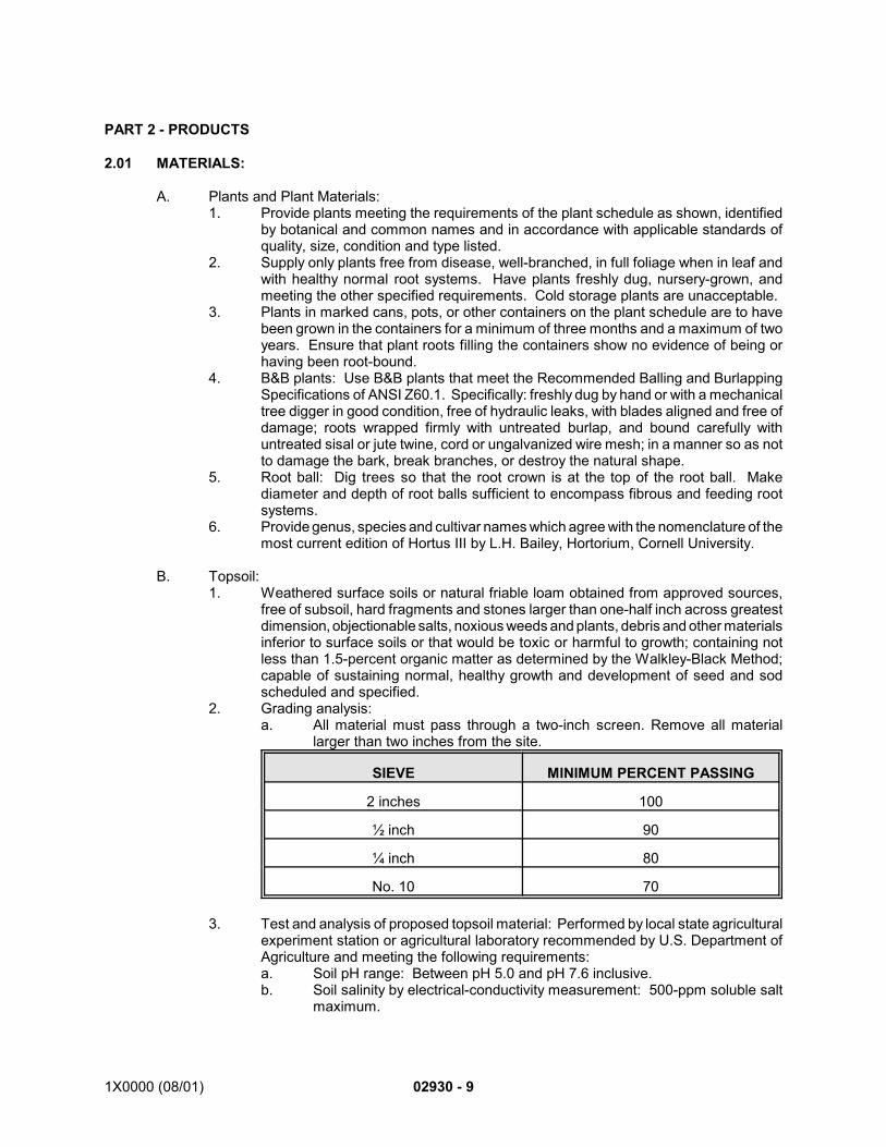
1X0000 (08/01) 02930 - 9
PART 2 - PRODUCTS
2.01 MATERIALS:
A. Plants and Plant Materials:1. Provide plants meeting the requirements of the plant schedule as shown, identified
by botanical and common names and in accordance with applicable standards ofquality, size, condition and type listed.
2. Supply only plants free from disease, well-branched, in full foliage when in leaf andwith healthy normal root systems. Have plants freshly dug, nursery-grown, andmeeting the other specified requirements. Cold storage plants are unacceptable.
3. Plants in marked cans, pots, or other containers on the plant schedule are to havebeen grown in the containers for a minimum of three months and a maximum of twoyears. Ensure that plant roots filling the containers show no evidence of being orhaving been root-bound.
4. B&B plants: Use B&B plants that meet the Recommended Balling and BurlappingSpecifications of ANSI Z60.1. Specifically: freshly dug by hand or with a mechanicaltree digger in good condition, free of hydraulic leaks, with blades aligned and free ofdamage; roots wrapped firmly with untreated burlap, and bound carefully withuntreated sisal or jute twine, cord or ungalvanized wire mesh; in a manner so as notto damage the bark, break branches, or destroy the natural shape.
5. Root ball: Dig trees so that the root crown is at the top of the root ball. Makediameter and depth of root balls sufficient to encompass fibrous and feeding rootsystems.
6. Provide genus, species and cultivar names which agree with the nomenclature of themost current edition of Hortus III by L.H. Bailey, Hortorium, Cornell University.
B. Topsoil:1. Weathered surface soils or natural friable loam obtained from approved sources,
free of subsoil, hard fragments and stones larger than one-half inch across greatestdimension, objectionable salts, noxious weeds and plants, debris and other materialsinferior to surface soils or that would be toxic or harmful to growth; containing notless than 1.5-percent organic matter as determined by the Walkley-Black Method;capable of sustaining normal, healthy growth and development of seed and sodscheduled and specified.
2. Grading analysis:a. All material must pass through a two-inch screen. Remove all material
larger than two inches from the site.
SIEVE MINIMUM PERCENT PASSING
2 inches 100
½ inch 90
¼ inch 80
No. 10 70
3. Test and analysis of proposed topsoil material: Performed by local state agriculturalexperiment station or agricultural laboratory recommended by U.S. Department ofAgriculture and meeting the following requirements:a. Soil pH range: Between pH 5.0 and pH 7.6 inclusive.b. Soil salinity by electrical-conductivity measurement: 500-ppm soluble salt
maximum.
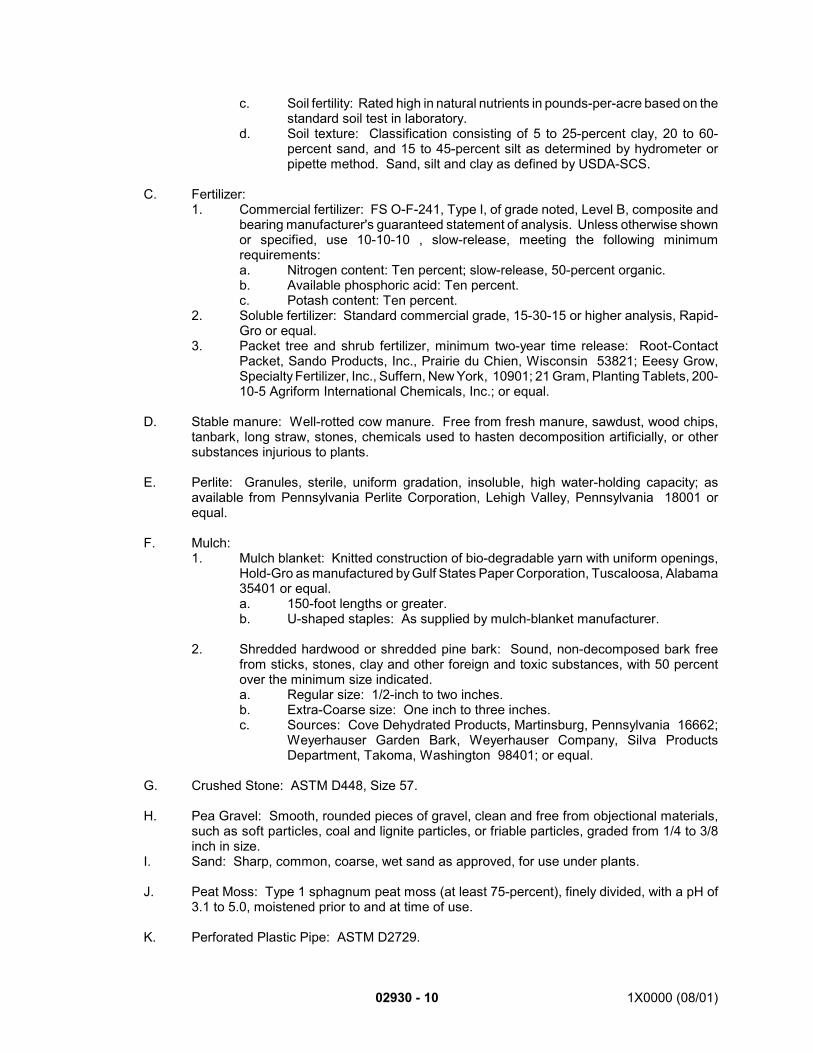
02930 - 10 1X0000 (08/01)
c. Soil fertility: Rated high in natural nutrients in pounds-per-acre based on thestandard soil test in laboratory.
d. Soil texture: Classification consisting of 5 to 25-percent clay, 20 to 60-percent sand, and 15 to 45-percent silt as determined by hydrometer orpipette method. Sand, silt and clay as defined by USDA-SCS.
C. Fertilizer:1. Commercial fertilizer: FS O-F-241, Type I, of grade noted, Level B, composite and
bearing manufacturer's guaranteed statement of analysis. Unless otherwise shownor specified, use 10-10-10 , slow-release, meeting the following minimumrequirements:a. Nitrogen content: Ten percent; slow-release, 50-percent organic.b. Available phosphoric acid: Ten percent.c. Potash content: Ten percent.
2. Soluble fertilizer: Standard commercial grade, 15-30-15 or higher analysis, Rapid-Gro or equal.
3. Packet tree and shrub fertilizer, minimum two-year time release: Root-ContactPacket, Sando Products, Inc., Prairie du Chien, Wisconsin 53821; Eeesy Grow,Specialty Fertilizer, Inc., Suffern, New York, 10901; 21 Gram, Planting Tablets, 200-10-5 Agriform International Chemicals, Inc.; or equal.
D. Stable manure: Well-rotted cow manure. Free from fresh manure, sawdust, wood chips,tanbark, long straw, stones, chemicals used to hasten decomposition artificially, or othersubstances injurious to plants.
E. Perlite: Granules, sterile, uniform gradation, insoluble, high water-holding capacity; asavailable from Pennsylvania Perlite Corporation, Lehigh Valley, Pennsylvania 18001 orequal.
F. Mulch:1. Mulch blanket: Knitted construction of bio-degradable yarn with uniform openings,
Hold-Gro as manufactured by Gulf States Paper Corporation, Tuscaloosa, Alabama35401 or equal.a. 150-foot lengths or greater.b. U-shaped staples: As supplied by mulch-blanket manufacturer.
2. Shredded hardwood or shredded pine bark: Sound, non-decomposed bark freefrom sticks, stones, clay and other foreign and toxic substances, with 50 percentover the minimum size indicated. a. Regular size: 1/2-inch to two inches.b. Extra-Coarse size: One inch to three inches.c. Sources: Cove Dehydrated Products, Martinsburg, Pennsylvania 16662;
Weyerhauser Garden Bark, Weyerhauser Company, Silva ProductsDepartment, Takoma, Washington 98401; or equal.
G. Crushed Stone: ASTM D448, Size 57.
H. Pea Gravel: Smooth, rounded pieces of gravel, clean and free from objectional materials,such as soft particles, coal and lignite particles, or friable particles, graded from 1/4 to 3/8inch in size.
I. Sand: Sharp, common, coarse, wet sand as approved, for use under plants.
J. Peat Moss: Type 1 sphagnum peat moss (at least 75-percent), finely divided, with a pH of3.1 to 5.0, moistened prior to and at time of use.
K. Perforated Plastic Pipe: ASTM D2729.
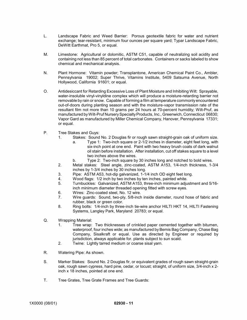
1X0000 (08/01) 02930 - 11
L. Landscape Fabric and Weed Barrier: Porous geotextile fabric for water and nutrientexchange; tear-resistant, minimum four ounces per square yard; Typar Landscape Fabric,DeWitt Earthmat, Pro 5, or equal.
M. Limestone: Agricultural or dolomitic, ASTM C51, capable of neutralizing soil acidity andcontaining not less than 85 percent of total carbonates. Containers or sacks labeled to showchemical and mechanical analysis.
N. Plant Hormone: Vitamin powder; Transplantone, American Chemical Paint Co., Ambler,Pennsylvania 19002; Super Thrive, Vitamins Institute, 5409 Satsuma Avenue, NorthHollywood, California 91601; or equal.
O. Antidesiccant for Retarding Excessive Loss of Plant Moisture and Inhibiting Wilt: Sprayable,water-insoluble vinyl-vinyldine complex which will produce a moisture-retarding barrier notremovable by rain or snow. Capable of forming a film at temperature commonly encounteredout-of-doors during planting season and with the moisture-vapor transmission rate of theresultant film not more than 10 grams per 24 hours at 70-percent humidity; Wilt-Pruf, asmanufactured by Wilt-Pruf Nursery Specialty Products, Inc., Greenwich, Connecticut 06830;Vapor Gard as manufactured by Miller Chemical Company, Hanover, Pennsylvania 17331;or equal.
P. Tree Stakes and Guys:1. Stakes: Sound No. 2 Douglas fir or rough sawn straight-grain oak of uniform size.
a. Type 1: Two-inch square or 2-1/2 inches in diameter, eight feet long, withsix-inch point at one end. Paint with two heavy brush coats of dark walnutoil stain before installation. After installation, cut off stakes square to a leveltwo inches above the wires.
b. Type 2: Two-inch square by 30 inches long and notched to bold wires.2. Metal stakes: Steel angle, zinc-coated, ASTM A153, 1/4-inch thickness, 1-3/4
inches by 1-3/4 inches by 30 inches long.3. Pipe: ASTM A53, hot-dip galvanized, 1-1/4 inch OD eight feet long.4. Wood flags: 1/2 inch by two inches by ten inches, painted white.5. Turnbuckles: Galvanized, ASTM A153, three-inch minimum adjustment and 5/16-
inch minimum diameter threaded opening fitted with screw eyes.6. Wires: Zinc-coated steel, No. 12 wire.7. Wire guards: Sound, two-ply, 5/8-inch inside diameter, round hose of fabric and
rubber, black or green color.8. Ring bolts: 1/4-inch by three-inch tie-wire anchor HILTI HKT 14, HILTI Fastening
Systems, Langley Park, Maryland 20783; or equal.
Q. Wrapping Material:1. Tree wrap: Two thicknesses of crinkled paper cemented together with bitumen,
waterproof, four inches wide; as manufactured by Bemis Bag Company, Chase BagCompany, Sisalkraft or equal. Use as directed by Engineer or required byjurisdiction, always applicable for. plants subject to sun scald.
2. Twine: Lightly tarred medium or coarse sisal yarn.
R. Watering Pipe: As shown.
S. Marker Stakes: Sound No. 2 Douglas fir, or equivalent grades of rough sawn straight-grainoak, rough sawn cypress, hard pine, cedar, or locust; straight, of uniform size, 3/4-inch x 2-inch x 18 inches, pointed at one end.
T. Tree Grates, Tree Grate Frames and Tree Guards:
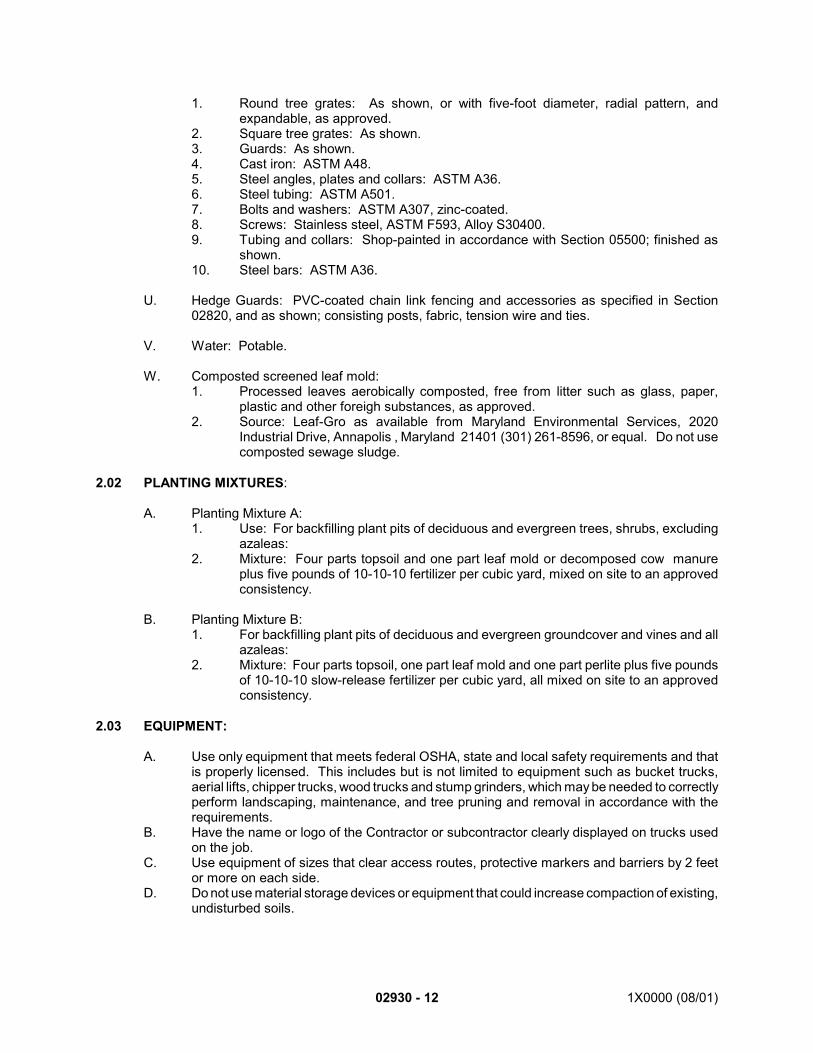
02930 - 12 1X0000 (08/01)
1. Round tree grates: As shown, or with five-foot diameter, radial pattern, andexpandable, as approved.
2. Square tree grates: As shown.3. Guards: As shown.4. Cast iron: ASTM A48.5. Steel angles, plates and collars: ASTM A36.6. Steel tubing: ASTM A501.7. Bolts and washers: ASTM A307, zinc-coated.8. Screws: Stainless steel, ASTM F593, Alloy S30400.9. Tubing and collars: Shop-painted in accordance with Section 05500; finished as
shown.10. Steel bars: ASTM A36.
U. Hedge Guards: PVC-coated chain link fencing and accessories as specified in Section02820, and as shown; consisting posts, fabric, tension wire and ties.
V. Water: Potable.
W. Composted screened leaf mold:1. Processed leaves aerobically composted, free from litter such as glass, paper,
plastic and other foreigh substances, as approved.2. Source: Leaf-Gro as available from Maryland Environmental Services, 2020
Industrial Drive, Annapolis , Maryland 21401 (301) 261-8596, or equal. Do not usecomposted sewage sludge.
2.02 PLANTING MIXTURES:
A. Planting Mixture A:1. Use: For backfilling plant pits of deciduous and evergreen trees, shrubs, excluding
azaleas:2. Mixture: Four parts topsoil and one part leaf mold or decomposed cow manure
plus five pounds of 10-10-10 fertilizer per cubic yard, mixed on site to an approvedconsistency.
B. Planting Mixture B:1. For backfilling plant pits of deciduous and evergreen groundcover and vines and all
azaleas:2. Mixture: Four parts topsoil, one part leaf mold and one part perlite plus five pounds
of 10-10-10 slow-release fertilizer per cubic yard, all mixed on site to an approvedconsistency.
2.03 EQUIPMENT:
A. Use only equipment that meets federal OSHA, state and local safety requirements and thatis properly licensed. This includes but is not limited to equipment such as bucket trucks,aerial lifts, chipper trucks, wood trucks and stump grinders, which may be needed to correctlyperform landscaping, maintenance, and tree pruning and removal in accordance with therequirements.
B. Have the name or logo of the Contractor or subcontractor clearly displayed on trucks usedon the job.
C. Use equipment of sizes that clear access routes, protective markers and barriers by 2 feetor more on each side.
D. Do not use material storage devices or equipment that could increase compaction of existing,undisturbed soils.
1X0000 (08/01) 02930 - 13
PART 3 - EXECUTION
3.01 PREPARATION FOR PLANTING:
A. See Article above on Scheduling and Coordination.
B. Pre-Planting Conference: See Article above, under Quality Assurance.
C. Locate and mark location of each underground utility.
D. Mark outlines on the ground for locations of individual trenches and planting beds asapproved. Have the Engineer approve marked locations before excavating.1. Drive marker stakes with at least eight inches projecting above surrounding ground
cover.2. Paint top four inches of each stake according to the following color schedule and
mark stakes with plant common name and sizes for each location:a. Evergreens: Blue.b. Deciduous trees: Red.c. Flowering trees: Yellow.
E. Do not permit personnel, vehicles, or equipment not directly associated with the work into theplanting areas.
F. Inspect Plants: Do not plant if plants appear damaged, unhealthy, insect infested, or if theroot ball is cracked or broken either before or during planting operation.
3.05 PRESERVATION OF EXISTING PLANTS:
A. Preserve and protect existing plants in accordance with the existing Plant Schedule as shownand with the requirements of Section 02205.
3.02 EXCAVATION FOR PLANTING:
A. Exercise care during entire time of excavation and planting work so as to prevent contactwith, disturbance of or unearthing of utilities and devices. Hand excavate wherevernecessary to ensure this level of care.
B. Exercise care in excavating tree pits at locations with existing drainage systems so as toprevent contact with, disturbance of or unearthing of drainage systems. Hand excavatewherever necessary to ensure this level of care. Place landscape fabric as shown. Stapleper manufacturer’s directions.
C. Plant Locations: Locate plants as shown on the Contract Drawings, from dimensions shown,and as approved by the Engineer after locations are marked per the Preparation for Plantingrequirements specified above.
D. Excavate pits, trenches, and beds with vertical sides and flat bottoms, to dimensions shown.
E. Excavate pits to a minimum depth of 24 inches, measured from finished grades, or asshown.
F. Make pits for bare-root plants to diameters at least 12 inches larger than the maximumspread of the roots and to minimum depth of at least 12 inches below the roots of the plantas placed.
02930 - 14 1X0000 (08/01)
G. Make pits for balled or potted plants, with ball or container less than 12 inches in diameter,to diameters at least 16 inches larger and depth to size of ball or container. Alleviate hardpancompaction by rototilling or discing sub-soil beneath plant.
H. Make pits for balled or potted plants, with ball or container 12 inches or greater in diameter,to diameters at least 24 inches larger and minimum depth to size of ball or container.
I. Install trench drain for trees on slopes greater than 3:1 in locations as shown. Excavate fourto six inches wide. Start bottom of trench at elevation of bottom of plant ball and extend awayon low side of plant location until daylighted. Fill bottom twelve inches of trench with peagravel. Backfill to surface with excavated material from trench. Blend surplus over area nextto trench. Cover surface with material to match the surrounding area.
J. Make beds for ground cover plants to the length and width shown with minimum depth of sixinches. Install landscape fabric beneath mulch layer, stapling per manufacturer’s directions.
K. Backfill plant pits that are abandoned due to unsuitable conditions with same excavatedmaterial, grade and seed.
L. Before the close of each working day, barricade open pits. When pits are excavated morethan fourteen days in advance of planting, backfill the excavations with the planting mixturespecified.
M. Remove and dispose of rocks, debris and excess excavated material off site. Set asideexcavated soil needed for backfill mix and to form saucers.
3.03 PLANTING:
A. Set plants plumb and straight with allowance for settlement. Set watering pipe as shown.
B. Place balled plants so that the top of the root ball bears the same relation to finish grade asit bore to previous finish grade in nursery, or 1/8 higher than depth of root ball= approximatelytwo inches higher. Place fertilizer packets or tablets in accordance with manufacturer'srecommendations alongside the base of root ball. Backfill with specified planting mixture in12-inch layers and tamp each layer to fill voids until planting mixture is at grade. Cut andremove burlap and lacing six inches away from trunk, or as approved. Leave remainder ofburlap and lacing intact. Soak plant with water containing plant hormone.
C. Open and remove containers from potted plants. If the growing medium is comprised of 75percent or more of peat, perlite, sand or like material other than soil, pull visible roots awayfrom container medium leaving the roots partially exposed. Place plants in plant pit or trenchand carefully place backfill planting mixture among exposed roots. Continue backfilling andtamping in six-inch layers until finish grade is reached. Soak with water containing planthormone.
D. Remove and store existing tree grates and replace when planting is complete.
E. Placement of bare-root plants: Place in pit or trench, cut off broken or frayed roots, spreadroot system, backfill with planting mixture in six-inch layers, settle to finish grade with watercontaining plant hormone.
F. Create saucer around isolated plants with soil to retain water unless otherwise shown. Bringbeds to smooth, even surfaces which will conform to established grade after full settlementhas occurred.Plant shrubs as a bed, using weed barrier fabric beneath mulch when shrubsare spaced less than six foot on center (6' O.C.), unless otherwise detailed.
1X0000 (08/01) 02930 - 15
G. Place specified planting mixture in groundcover bed at six-inch depth or as otherwise shownin contract drawing detail , place landscape weed barrier and then top with a layer of mulchto depth of three inches after compaction.
H. Remove groundcover plants from pots with root system intact and set in mulched plantingbeds, cut through weed barrier, in the spacing and arrangement shown. Work soil firmlyaround each plant and restore the mulching material. Settle to finish grade with watercontaining plant hormone. On slopes greater than 2:1, after preparing planting beds andmulching, but prior to planting, apply mulch blanket as directed and staple according tomanufacturer's instructions.
I. When pits are dug in wet areas or where subsoil will not permit drainage as shown, set planthigher than normal using extra depth of crushed of crushed stone or sand, up to 12 inchestotal depth, to keep ball from settling. Set top of plant root ball up to six inches higher thangrade, as directed. Blend the immediate area outside the saucer with suitable soil to meetexisting grade.
J. Topsoil or approved fine, dry subsoil excavated or augered from plant pits may be used toform saucers. If plant pits are augered, break down side of the hole to permit rootpenetration.
K. Create soil berm around downhill portion of planting pits on slopes.
L. Cultivating: Cultivate trenches and shrub beds to the line shown. Cultivate area aroundisolated plants at least six inches beyond diameter of pit.
M. Mulching: After planting and cultivating are completed, spread a layer of mulch on finishedgrade around plants to a depth of three inches after compaction. Lay landscape fabricbeneath shrubbery beds, groundcover areas, and in tree pits, stapling as necessary permanufacturer’s directions. Spread mulch around isolated plants over an area at least sixinches greater than diameter of the pit and extend mulch over berm saucers as shown.Completely cover trenches and shrubbery beds with mulch. In planters and beds, spread alayer of mulch to depth of three inches after compaction.
N. Pruning: Prune plant material after installation as approved to thin branches and foliage andyet retain species shape and trim hedges as shown. Do not cut leaders.1. Remove limbs, branches, canes and runners which require trimming with a clean cut
flush with trunk or adjacent stem.2. When pruning lateral branches, cut at the same angle as that at which the buds are
growing from the branches. Cut at a distance of 1/8-inch to 1/4-inch beyond thebuds to avoid injuring them.
3. Sterilize cutting tools with alcohol before proceeding to next plant after pruning outinfected twigs and branches.
O. Planting in Planters: Install crushed stone, landscape fabric and weed barrier, plantingmixture and mulch as shown. Mound planting mix as shown for positive drainage. Do notwork soil when frozen.
P. Flower Beds: Plant flowers as shown, at planting seasons recommended by regionaljurisdictions and/or growers.
Q. Wrapping: Check with Engineer for necessity. For plants prone to sun scald use immediatelyafter planting, spirally wrap trunk and main branches of trees with an overlay of two inchesstarting at the bottom. Tie wrap securely in place with twine.
02930 - 16 1X0000 (08/01)
R. Guying: Within three days after planting, guy each tree four-inch caliper or larger as shown.Protect trees at points of contact by use of wire guards. After installation, cut stakes squareto a level two inches above the wires.
S. Staking: Support trees smaller than four-inch caliper within three days after planting bystaking at perimeter line of ball as specified and to sufficient depth to hold tree rigid. Drivestakes vertically to achieve uniform height of five feet-six inches above finish grade or asdirected. Do not twist or pull. Wire tree with wire guards interlocked to each stake at fourinches above finish grade, or as directed.1. Planting areas: Three stakes, 120-degrees apart.2. Trees with grates: Four stakes, 90-degrees apart.
T. Installation of Hedge Guard: Space hedge guard posts at a maximum of eight feet oncenters. On curves with radii less than 100 feet, space hedge guard posts at a maximum offour feet on centers. Drive posts plumb to a height of three feet-six inches; protect end ofpipe. Install one-cubic foot of concrete around base of end post in each run to serve as pullanchor. Secure fabric to posts with ties spaced 12 inches on centers. Install tension wire twoinches below top of fabric. Install permanent caps on posts.
U. Removal of Seals and Tags: As approved.
3.04 EXISTING TREE PRUNING AND REMOVAL:
A. Safety:1. Conduct operations in accordance with national and local fire and safety codes, laws,
rules, regulations and ANSI Z133.1 Safety Requirements for Pruning, Trimming,Repairing, Maintaining and Removing Trees and Cutting Brush.
2. Have employees wear reflective, bright orange vests while conducting operations inor adjacent to roadways.
3. Do not permit any one except the operator within six feet of a power saw.4. Block off the work area to pedestrians, other workers and vehicles.5. Look for, note and report to the Engineer in writing the presence of the slightest
structural weakness, disease conditions, decayed trunk or branches, split crotchesor branches, or other hazardous condition that has potential for damage to propertyor personal injury.
B. Tree Pruning:1. Prune and thin trees when in foliage according to the Pruning Standards for Shade
Trees (revised 1988) by the National Arborist Association. The classes of pruningare as follows:a. Class I Fine Pruning: Fine pruning consists of removing dead, dying,
diseased, interfering, objectionable, obstructing and weak branches, as wellas selective thinning to lessen wind resistance. Removal of such branchesincludes those on the main trunks as well as those within the leaf area. Anoccasional branch as described above up to ½-inch in diameter may remainwithin the main leaf area where it is not practical to remove.
b. Class II Medium Pruning: Medium pruning consists of removing dead,dying, diseased, interfering, objectionable and weak branches on the maintrunk as well as those within the leaf area. An occasional branch up to oneinch in diameter may remain within the main leaf area where it is notpractical to remove.
c. Class III Coarse Pruning: Coarse pruning consists of removing dead,diseased, or obviously weak branches, two inches in diameter or greater.
d. Class IV Cutting Back or Drop Crotch Pruning: Cutting back or drop crotchpruning consists of reducing tops, sides, underbranches or individual limbs.
1X0000 (08/01) 02930 - 17
1) Undertake this practice only in cases of utility line interference, orwhere certain portions of the roots or root systems have beenseverely damaged, or when there is unusual and rapid tree growth,where it is necessary to reduce the top, sides or underbranches, orfor specific topiary training or dwarfing.
2) When cutting back, do not reduce more than 1/3 of the total area asa single operation. When cutting back trees, only drop crotch asmuch as necessary. Make every effort to cut back to a lateral, one-third of the diameter of the cut being made.
3) In reducing overall size, give attention to the symmetricalappearance. Keep top higher and sides reduced in order tomaintain a tree-like form.
4) Contact the Engineer prior to pruning a tree specified as Class I orClass II pruning if said pruning will reduce the surface area of thetree by more than 25 percent. Report tree structural problems.
2. Cut back dead, diseased and dying wood into healthy wood.3. On trees known to be diseased, disinfect tools after use on each tree with methyl
alcohol at 70 percent (denatured wood alcohol diluted appropriately with water) orChlorox bleach solution.
4. Remove weak crotches, defined as split or rotted wood between two trunks of limbsthat may break and fall during high wind.
5. Where branches cross and rub together or are forming a V-crotch, remove onebranch without ruining the appearance of the tree.
6. Selectively prune trees which are developing more than one dominant leader in orderto promote a single dominant leader by sub-dominating the other competitivebranches. Make selection of the dominant leader with consideration of the tree'snatural form, health, and structure.
7. Inspect old injuries. Where appropriate, trace those not closing properly and wherecallus growth is not already completely established.
8. Remove girdling roots.9. Trimming for clearance:
a. Trim trees to provide three feet of clearance from adjacent buildings andstructures.
b. For street trees and trees over walks, trails, and picnic areas over six inchesdiameter at breast height (dbh), remove lateral limbs and water sprouts fromthe main trunk of the tree to a height of 12 feet above the ground. For treesover 10 inches dbh, remove lateral limbs and water sprouts from the maintrunk of the tree to a height of fourteen feet above the ground.
c. Prune trees in the vicinity of electrical or phone lines so as to provide six toeight feet of clearance between lines and the nearest limb.
10. Remove branches with a slanting cut starting just above a vigorous bud or shoot andrunning back across the limb at a 45 degree angle. Make cuts sufficiently close tothe trunk or parent limb, without cutting into the branch collar or leaving a protrudingstub, so that closure can readily start under normal conditions. Make clean cuts.
11. Precut branches that are too heavy to handle to prevent splitting or peeling the bark.Where damage to other trees, foliage or property is possible, lower branches safelyto the ground by ropes or equipment. Under no circumstances drop branches ormain trunks freely onto a road, shoulder or paved surface.
12. Trim salvageable branches by removing smaller branches flush with the surface ofthe main branch.
13. Do not remove entire or large portions of healthy, sound limbs in order to facilitatethe removal of dead or dying terminals.
14. Complete required pruning and removals at the site of each tree, including removalof logs and debris, before initiating work on the next tree.
15. Do not use chain saws or circular power blades to remove branches less than twoinches in diameter.
02930 - 18 1X0000 (08/01)
16. Do not use wounding paint,17. Do not use climbing hooks while pruning.
C. Tree and Stump Removal:1. Take every reasonable precaution, including but not limited to topping, sectioning
and lifting of trees, diagnosing soundness of existing wood, and planning escaperoutes for workers to prevent damage to other vegetation, property, utility lines andpersons and to prevent gouging and erosion of soils as a result of removaloperations.
2. Fell trees only when there is an adequate felling area at least equal in radius to theheight of the tree. Top and remove in sections trees that cannot be felled due toproximity of buildings, conductors, adjacent trees, or lack of an adequate felling area.
3. Properly rope, guy, or anchor trees to be felled that may cause damage to propertyor existing vegetation.
4. Climbing hooks may be worn for tree removal work.5. Remove stumps to a depth of 12 inches below grade. Backfill and level the stump
hole with clean wood-waste material.6. Completely remove each tree, including removal of logs and debris, before initiating
work on the next tree.
D. Debris removal:1. Cut branches over six inches into 18 to 24 inch lengths.2. Chip material less than six inches in diameter.3. Collect, deliver, and unload wood and chips to a location specified by the Engineer.
If approved, chips may be blown into adjacent natural areas.4. Remove wood, debris and chips on a daily basis. Sale of wood is not permitted on
the project site.
3.05 INTERIM MAINTENANCE (UNTIL SCI):
A. While planting is in progress, perform interim maintenance and management practices onwork completed. During the post-planting period and until the SCI, properly care for plantsfurnished; performing watering, cultivating, and other maintenance tasks necessary to keepthe plants in a live, healthy condition.
B. Maintain plants and work incidental thereto by performing the following and other operationsof care to promote root growth and plant health so that plants are in an approved conditionthroughout the interim maintenance period. Perform work in a manner which maintains theoriginal intent of the reforestation and landscape design. Submit maintenance reports andschedules as specified.1. Watering and draining: Water plants as required twice each month, or more
frequently if weather conditions require such, as directed.2. Weeding: Weed by hand the mulched area around each plant and within bedded
areas, at least twice each month during the growing season. Remove weeds fromthe site immediately. As directed, approved chemical weed killers may be used withprecautions to prevent undesired damage resulting from such use. Submit Herbicidespill plan and daily use log , when required by jurisdictional agency.
3. Pruning: Prune plants to ensure a desired growth habit and to remove dead wood,as directed and approved.
4. Mulching: Mulch to maintain the depth as indicated or as directed.5. Securing stakes: Replace or adjust as necessary to maintain stability.
1X0000 (08/01) 02930 - 19
C. Periodically inspect plants during the interim maintenance period and notify the Engineer inwriting of suspected problems. The Contractor is responsible for insect and disease controlon Authority property. Take necessary measures to ensure effectiveness of the treatmentand plant survival. Insect and disease control are the responsibility of the NPS andMNCPPC ,unless brought in by Contractor’s plant source.
3.06 SOIL DENSITY ADJUSTMENT:
A. After completion of work and before Substantial Completion Inspection (SCI), have the soil-proctor testing along work routes and storage areas performed as required above underSubmittals, Documentation.
B. Adjust unacceptably compacted soil to a maximum of 75 percent maximum dry density inaccordance with the Engineer’s directions and at no additional cost to the Authority. In rootprotection zone, use of decompaction machinery is unacceptable.
3.07 SUBSTANTIAL COMPLETION INSPECTION (SCI):
A. A Substantial Completion Inspection will be held by the Engineer after completion of plantingto verify that the work was performed as defined in the Contract Documents.
B. Do not remove tags, labels, etc. after SCI. These are needed during ConcurrentMaintenance and Warranty period. Remove such identifications only at final acceptance.
C. SCI commences the Concurrent Maintenance and Warranty Period of the Contract for itemsaccepted as of this inspection.
3.08 CONCURRENT MAINTENANCE AND WARRANTY PERIOD:
A. See warranty requirements in General Provisions, General Requirements, and specified inPart 1 of this section.
B. After the Engineer has accepted the completed work in accordance with SCI, perform post-planting maintenance and plant management concurrent with the warranty period. Duringthis period, properly care for plants; performing the following and other beneficial operationsof care for promotion of root growth and plant life so that each plant is in an approvedcondition at the Substantial Completion Inspection and throughout the maintenance period:1. Watering and draining: Water plants as required twice each month. Every two
weeks during the growing season, examine or sound the watering pipe at each plantto determine if too much water is collecting in the plant pit. Remove surplus waterby pump or syphon without staining the pavement. Bi-weekly check relative moisturecontent of soil for typical tree and typical area of shrub or hedge planting; weeklyduring the months of July and August. Use Peerless Moisture Indicator, Tree-Type;or equal; following manufacturer's recommendations. Provide sufficient water tomaintain relative moisture content of 25 to 30 percent. Provide water, fittings, hose,and water tanks as required to perform watering operation.
2. Weeding: As necessary, perform seasonal weeding in the mulched area aroundeach plant and in bedded areas, at least twice each month. Pull roots by hand oruse approved chemical weed killers . Submit Herbicide spill plan and daily use log,when required by jurisdictional agency. Correct any damage resulting from such useand no not spray when winds are over . Remove weeds from the site.
02930 - 20 1X0000 (08/01)
3. Controlling insects and diseases: Treat plants year-round with an approvedchemical spray or systemic chemical as necessary to prevent insects, disease andfungus. Take necessary measures to ensure effectiveness of the treatment andplant survival. Submit Pesticide spill plan and daily use log, when required byjurisdictional agency. Protect vehicles and construction in the vicinity from damageor staining.
4. Pruning: Prune plants during each growing season to develop a desired growthhabit and to remove dead wood.
5. Fertilizing: Fertilize trees, shrubs, hedge plants and groundcover once between May15 and July 1 with 15-30-15 soluble fertilizer, or equal, at the manufacturer'srecommended rate.
6. Edging: At least twice during the growing season, edge around the mulched areaof each plant.
7. Mulching: Mulch to maintain the depth as shown.8. Wrapping: Rewrap to maintain protection and a neat appearance. Remove
wrapping at end of first winter period after planting as approved. Repair damagedareas previously covered by wrapping.
9. Securing guys and stakes: Replace or adjust to maintain stabilization. Before endof maintenance period, remove stakes and guys above grade.
C. Removing and Replacing Plants: After early Spring and early Fall seasonal inspections andwritten notification by the Engineer of the plant material to be removed and replaced, proceedas follows:1. Remove or cut off at ground line said plant materials that are dead or in an
unhealthy, unsightly or badly impaired condition, within three weeks after notification.2. Replace the plant materials during the next specified planting season with healthy
plants of the same kinds and sizes as originally specified. Make such replacementsin the same manner as specified for the original planting. Notify the Engineer priorto performing the work.
3. Attach color-coded tag indicating replacement, and mark with the date ofreplacement in weather-resistant ink, keyed to the Plant Schedule shown. Securelyattach tag to each plant in a manner that will not restrict growth. Maintain tag onplants until removal is directed by the Engineer.
4. Failure to notify Contractor of plant material to be removed or replaced does notrelieve the Contractor from warranty obligations.
D. The Contractor will not be held responsible or liable for damage by animals, by malicious orcareless human agencies over which the Contractor has no control, by fire or storm, or byvehicular accidents by others that occur after the Substantial Completion Inspection.
E. Clean-Up: Leave paved surfaces broom clean and stain free. Remove rubbish and debriscaused by this work. Keep site clean during maintenance period.
3.09 FINAL ACCEPTANCE:
A. Prior to final acceptance, perform final cleanup, including removal of stakes above grade,guys, signs and other items as directed by the Engineer, and for remulching plants and bedsto a loose measurement as specified. Place no mulch against a trunk or stem.
B. Cut off watering pipe projecting above the mulch level.
C. Replace rejected plants as specified.
D. Submit maintenance reports and schedules as specified.
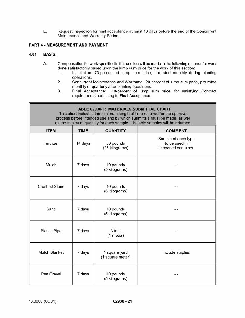
1X0000 (08/01) 02930 - 21
E. Request inspection for final acceptance at least 10 days before the end of the ConcurrentMaintenance and Warranty Period.
PART 4 - MEASUREMENT AND PAYMENT
4.01 BASIS:
A. Compensation for work specified in this section will be made in the following manner for workdone satisfactorily based upon the lump sum price for the work of this section:1. Installation: 70-percent of lump sum price, pro-rated monthly during planting
operations.2. Concurrent Maintenance and Warranty: 20-percent of lump sum price, pro-rated
monthly or quarterly after planting operations.3. Final Acceptance: 10-percent of lump sum price, for satisfying Contract
requirements pertaining to Final Acceptance.
TABLE 02930-1: MATERIALS SUBMITTAL CHARTThis chart indicates the minimum length of time required for the approval
process before intended use and by which submittals must be made, as wellas the minimum quantity for each sample. Useable samples will be returned.
ITEM TIME QUANTITY COMMENT
Fertilizer 14 days 50 pounds(25 kilograms)
Sample of each typeto be used in
unopened container.
Mulch 7 days 10 pounds(5 kilograms)
- -
Crushed Stone 7 days 10 pounds(5 kilograms)
- -
Sand 7 days 10 pounds(5 kilograms)
- -
Plastic Pipe 7 days 3 feet(1 meter)
- -
Mulch Blanket 7 days 1 square yard(1 square meter)
Include staples.
Pea Gravel 7 days 10 pounds(5 kilograms)
- -
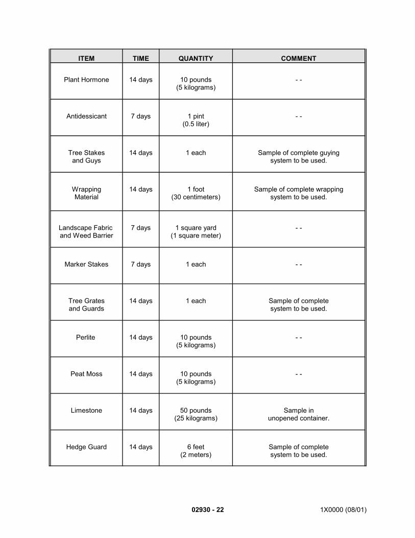
ITEM TIME QUANTITY COMMENT
02930 - 22 1X0000 (08/01)
Plant Hormone 14 days 10 pounds(5 kilograms)
- -
Antidessicant 7 days 1 pint(0.5 liter)
- -
Tree Stakesand Guys
14 days 1 each Sample of complete guyingsystem to be used.
WrappingMaterial
14 days 1 foot(30 centimeters)
Sample of complete wrappingsystem to be used.
Landscape Fabric and Weed Barrier
7 days 1 square yard(1 square meter)
- -
Marker Stakes 7 days 1 each - -
Tree Gratesand Guards
14 days 1 each Sample of completesystem to be used.
Perlite 14 days 10 pounds(5 kilograms)
- -
Peat Moss 14 days 10 pounds(5 kilograms)
- -
Limestone 14 days 50 pounds(25 kilograms)
Sample inunopened container.
Hedge Guard 14 days 6 feet(2 meters)
Sample of completesystem to be used.
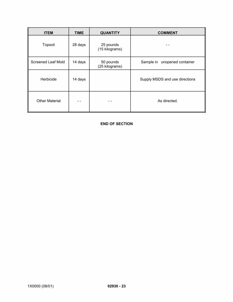
ITEM TIME QUANTITY COMMENT
1X0000 (08/01) 02930 - 23
Topsoil 28 days 25 pounds(15 kilograms)
- -
Screened Leaf Mold 14 days 50 pounds(25 kilograms)
Sample in unopened container
Herbicide 14 days Supply MSDS and use directions
Other Material - - - - As directed.
END OF SECTION