STANDARD SPECIFICATIONS - Athens-Clarke County
100
STANDARD SPECIFICATIONS FOR WATER MAIN CONSTRUCTION PUBLIC UTILITIES DEPARTMENT UNIFIED GOVERNMENT OF ATHENS-CLARKE COUNTY GEORGIA December 2008
-
Upload
khangminh22 -
Category
Documents
-
view
0 -
download
0
Transcript of STANDARD SPECIFICATIONS - Athens-Clarke County

STANDARD SPECIFICATIONS FOR WATER MAIN
CONSTRUCTION
PUBLIC UTILITIES DEPARTMENT UNIFIED GOVERNMENT OF ATHENS-CLARKE COUNTY GEORGIA December 2008

PREFACE
These Standard Specifications have been prepared to complement
and include by reference the Standard Detail Drawings and to
provide the qualitative requirements for products, materials and
workmanship for construction of additions to and replacements of
the water system (main sizes 8 inches through 16 inches and
services) which is under the jurisdiction of the Unified Government of
Athens-Clarke County, Georgia.
All references in these Standard Specifications to "Engineer" shall
mean the legal and authorized representative of the Department of
Public Utilities, Unified Government of Athens-Clarke County. All
references to "Project" shall mean the work being constructed under
the jurisdiction of these Standard Specifications. All references to
"Contractor" shall mean the individual, company or corporation
constructing work under the jurisdiction of these Standard
Specifications. All references to "Drawings" shall include, by
reference, the Standard Detail Drawings accompanying these
Standard Specifications.
These Standard Specifications may be supplemented due to
exceptional circumstances, with such noted on the Drawings or
supplemental Specifications approved by Director of Public Utilities.

Table of Contents
Athens-Clarke County Revision 0 December 2008
STANDARD SPECIFICATIONS
Division 2 - Sitework
02110 Clearing and Grubbing
02125 Soil Erosion and Sediment Control
02225 Trench Excavation and Backfill
02229 Bore and Jack Crossings
02575 Removing and Replacing Pavement
02665 Water Mains and Accessories
02668 Water Service Connections
Appendix A
Approved Manufacturer's List for Water Main Construction
Appendix B
Contractor's Warranty Obligation
Policy and/or Procedure Statement
Maintenance Guarantee of Subdivision Improvements
STANDARD DETAIL DRAWINGS
W-1 Water Pipe Bedding & Backfill
W-2 Fire and Domestic Service
W-3 Fire and Domestic Irrigation Service
W-4 Fire Service
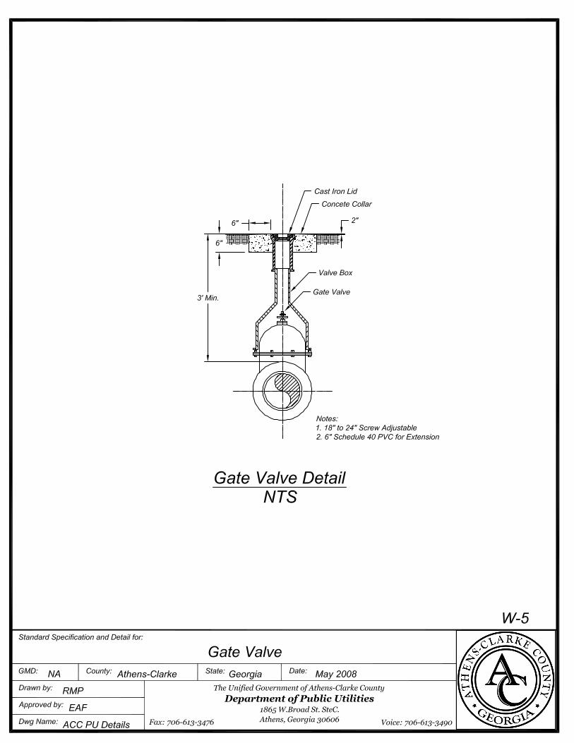
W-5 Gate Valve
W-6 Fire Hydrant
W-7 Fire Hydrant Dead End
W-8 Back Tap
W-9 Water Service Connection
W-10 Vertical Bend
W-11 Valve Marker
W-12 Thrust Block
G-1 Paving Cut Detail
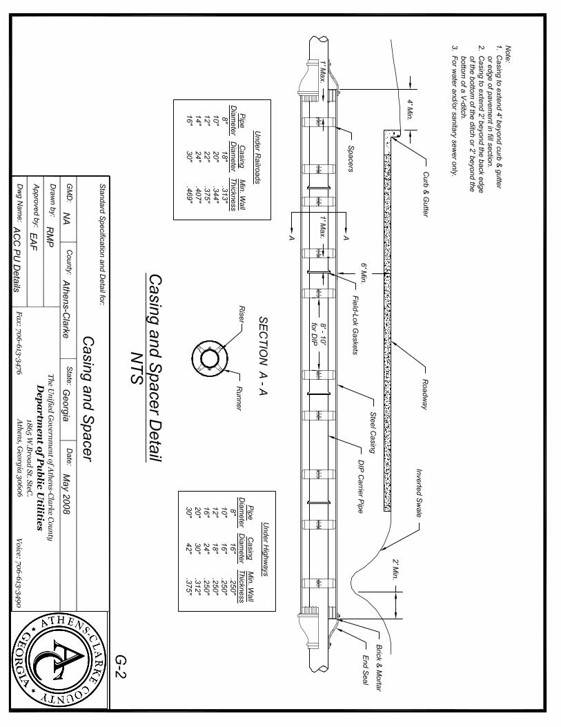
G-2 Casing and Spacer

Section 02110 Clearing and Grubbing
Athens-Clarke County Revision 0 December 2008
Part 1 General
1.01 Scope
A. Clearing and grubbing includes, but is not limited to, removing from the Project site,
trees, stumps, roots, brush, structures, abandoned utilities, trash, debris and all other
materials found on or near the surface of the ground in the construction area and
understood by generally accepted engineering practice not to be suitable for
construction of the type contemplated. Precautionary measures that prevent damage
to existing features to remain are part of the Work.
B. Clearing and grubbing operations shall be coordinated with temporary and permanent
erosion and sedimentation control procedures, as required by state Erosion and
Sedimentation, Georgia Manual (latest edition).
1.02 Quality Assurance
A. The Contractor shall comply with applicable codes, ordinances, rules, regulations and
laws of local, municipal, state or federal authorities having jurisdiction over the Project.
All required permits of a temporary nature shall be obtained for construction operations
by the Contractor.
B. Open burning will not be allowed.
1.03 Job Conditions
A. Location of the Work: The area to be cleared and grubbed is shown schematically on
the Drawings or specified below. It includes all areas designated for construction.
B. The Contractor shall comply with conditions of special agreements and easements
negotiated by the Unified Government of Athens-Clarke County (UGACC) with private
property owners and public agencies.
Part 2 Products
2.01 Equipment
The Contractor shall furnish equipment of the type normally used in clearing and
grubbing operations including, but not limited to, tractors, trucks, loaders and root rakes.
Part 3 Execution
3.01 Scheduling of Clearing

02110 - 2 Clearing and Grubbing
Athens-Clarke County Revision 0 December 2008
A. The Contractor shall clear at each construction site only that length of the right-of-way,
permanent or construction easement which would be the equivalent of one month's
pipe laying.
B. UGACC may permit clearing for additional lengths of the pipe line provided that
temporary erosion and sedimentation controls are in place and a satisfactory stand of
temporary grass is established. Should a satisfactory stand of grass not be possible,
no additional clearing shall be permitted beyond that specified above.
C. A satisfactory stand of grass shall have no bare spots larger than one square yard.
Bare spots shall be scattered and the bare area shall not comprise more than one
percent of any given area.
3.02 Clearing and Grubbing
A. Clear and grub the permanent easement or 5 feet on each side of the pipeline,
whichever is greater, before excavating. Remove all trees, growth, debris, stumps and
other objectionable matter. Clear the construction easement or road right-of-way only if
necessary.
B. Materials to be cleared, grubbed and removed from the Project site include, but are not
limited to, all trees, stumps, roots, brush, trash, organic matter, paving, miscellaneous
structures, houses, debris and abandoned utilities.
C. Grubbing shall consist of completely removing roots, stumps, trash and other debris
from all graded areas so that topsoil is free of roots and debris. Topsoil is to be left
sufficiently clean so that further picking and raking will not be required.
D. All stumps, roots, foundations and planking embedded in the ground shall be removed
and disposed of. Piling and butts of utility poles shall be removed to a minimum depth
of two feet below the limits of excavation for structures, trenches and roadways or two
feet below finish grade, whichever is lower.
E. Landscaping features shall include, but are not necessarily limited to, fences, cultivated
trees, cultivated shrubbery, property corners, man-made improvements, subdivision
and other signs within the right-of-way and easement. The Contractor shall take
extreme care in moving landscape features and promptly re-establishing these
features. Existing structures shall be relocated such that they are off the easement.
F. Surface rocks and boulders shall be grubbed from the soil and removed from the site if
not suitable as rip rap.
G. Where the tree limbs interfere with utility wires, or where the trees to be felled are in
close proximity to utility wires, the tree shall be taken down in sections to eliminate the
possibility of damage to the utility.
H. Any work pertaining to utility poles shall comply with the requirements of the
appropriate utility.
02110 - 3 Clearing and Grubbing
Athens-Clarke County Revision 0 December 2008
I. All fences adjoining any excavation or embankment that, in the Contractor's opinion,
may be damaged or buried, shall be carefully removed, stored and replaced. Any
fencing that, in UGACC's opinion, is significantly damaged shall be replaced with new
fence material.
J. The Contractor shall exercise special precautions for the protection and preservation of
trees, cultivated shrubs, sod, fences, etc. situated within the limits of the construction
area but not directly within excavation and/or fill limits. The Contractor shall be held
liable for any damage the Contractor's operations have inflicted on such property.
K. The Contractor shall be responsible for all damages to existing improvements resulting
from Contractor's operations.
3.03 Disposal of Debris
The debris resulting from the clearing and grubbing operation shall be hauled to a
disposal site secured by the Contractor and shall be disposed of in accordance with all
requirements of federal, state, county and municipal regulations. No debris of any kind
shall be deposited in any stream or body of water, or in any street or alley. No debris
shall be deposited upon any private property except with written consent of the property
owner. A copy of written consent shall be provided to UGACC for permanent records.
In no case shall any material or debris be left on the Project, shoved onto abutting
private properties or buried on the Project.
END OF SECTION

Section 02125 Erosion and Sedimentation Control
Athens-Clarke County Revision 0 December 2008
Part 1 General
1.01 Scope A. The work specified in this Section consists of providing, maintaining and removing
temporary erosion and sedimentation controls.
B. Temporary erosion controls, include, but are not limited to, grassing, mulching, watering
and reseeding on-site surfaces and spoil and borrow area surfaces, and providing
interceptor ditches at ends of berms and at those locations which will ensure that
erosion during construction will be either eliminated or maintained within acceptable
limits as established by the “Erosion and Sedimentation Act of 1975” as amended
(O.C.G.A. § 12-7-1 et seq.), Section 402 of the Federal Clean Water Act, and
applicable codes, ordinances, rules, regulations and laws of local and municipal
authorities having jurisdiction.
C. Temporary sedimentation controls include, but are not limited to, silt dams, traps,
barriers, filter stone and appurtenances at the foot of sloped surfaces which will ensure
that sedimentation pollution will be either eliminated or maintained within acceptable
limits as established by the Federal Clean Water Act of 1987, as amended.
D. Land disturbance activity shall not commence until the Land Disturbance Permit has
been issued, which authorizes land disturbance activities.
E. Basic Principles
1. Conduct the earthwork and excavation activities in such a manner to fit the
topography, soil type and condition.
2. Minimize the disturbed area and the duration of exposure to erosion elements.
3. Stabilize disturbed areas immediately. Do not allow any undisturbed area to
remain unstabilized for fourteen (14) days or more.
4. Safely convey run-off from the site to an outlet such that erosion will not be
increased off site.
5. Retain sediment on site that was generated on site.
6. No construction activities shall occur within a dedicated stream buffer, unless
otherwise approved by the Unified Government of Athens-Clarke County
(UGACC) and the Georgia EPD.
7. All erosion and sedimentation control measures shall be designed for a minimum
25-year storm event.
8. Construct erosion and sedimentation control devices prior to or concurrent with
land disturbing activities.

02125-2 Erosion and Sedimentation Control
Athens-Clarke County Revision 0 December 2008
9. Minimize encroachment on water courses.
F. Temporary Erosion and Sedimentation Control: In general, temporary erosion and
sedimentation control procedures shall be directed toward:
1. Preventing soil erosion at the source.
2. Preventing silt and sediment from entering any waterway if soil erosion cannot be
prevented.
3. Preventing silt and sediment from migrating downstream in the event it cannot be
prevented from entering the waterway.
G. Permanent Erosion Control: Permanent erosion control measures shall be
implemented to prevent sedimentation of the waterways and to prevent erosion of the
Project site.
1.02 Quality Assurance A. General: Perform all work under this Section in accordance with all pertinent rules and
regulations including, but not necessarily limited to, those stated above and these
Specifications.
B. Conflicts: Where provisions of pertinent rules and regulations conflict with these
Specifications, the more stringent provisions shall govern.
C. The Contractor shall provide to UGACC, prior to initiating land disturbance activities, the
name and 24-hour phone number of the individual responsible for inspection,
installation and maintenance of erosion and sedimentation control devices on a 24 hour
everyday basis.
1.03 Quality Standards
A. Part III, Special Condition, Management Practices, Permit Violations and Other
Limitations of the General Permit allows for the discharge of waterline flushing provided
flows are not contaminated with process materials or pollutants. Chlorine shall be
removed prior to discharging water and waterline.
B. Fluids used for horizontal directional drilling shall not be discharged without treatment
to reduce the turbidity to less than twenty-five (25) nephelometric turbidity units (NTU).
C. Erosion Control features installed shall be effectively maintained to control erosion
within the limits of the project and to control the discharge of stormwater from disturbed
areas such that turbidity of the stream shall not exceed twenty-five (25) NTU higher
than the turbidity level of the stream immediately up stream of construction. Turbidity
testing will be done by UGACC. Any erosion control devices damaged by contractor or
any of his subcontractors either by neglect, by his construction methods or for any other
reasons including acts of nature shall be immediately repaired by the contractor at no

02125-3 Erosion and Sedimentation Control
Athens-Clarke County Revision 0 December 2008
additional cost to UGACC.
1.04 Dust Control Dust from any of the contractor’s activities shall be controlled to keep dust pollution
to a minimum. Comply with Georgia Environmental Protection Division Air Pollution
Standards for Nuisance Dust Control. Contractor may be directed to wet areas
where dust may be or is a problem to achieve the desired results.
Part 2 Products
2.01 Temporary Erosion and Sediment Control Materials A. Silt Fence: Silt fence shall meet the requirements of Section 171 - Temporary Silt
Fence of the Department of Transportation, State of Georgia, Standard Specification,
latest edition.
B. Hay Bales: Hay bales shall be clean, seed-free cereal hay.
C. Stone Check Dams: Stone shall conform to the requirements of Section 805.01 of the
Georgia Department of Transportation Standard Specification, latest edition, for Stone
Dumped Rip Rap except the stone shall be 8-inches or less at the greatest dimension.
D. Construction Exit Stone: Use sound, tough, durable stone resistant to the action of air
and water. Slabby or shaley pieces will not be acceptable. Aggregate size shall be in
accordance with the National Stone Association Size R-2 (1.5 to 3.5-inch stone) or
Type 3 rip rap stone conforming to Section 805.01 of the Georgia Department of
Transportation Standard Specifications.
2.02 Rip Rap
A. Use sound, tough, durable stones resistant to the action of air and water. Slabby or
shaley pieces will not be acceptable. Specific gravity shall be 2.0 or greater. Rip rap
shall have less than 66 percent wear when tested in accordance with AASHTO T-96.
Unless shown or specified otherwise, stone rip rap shall be Type 1 rip rap.
B. Type 1 Rip Rap: The largest pieces shall have a maximum volume of two cubic feet.
At least 35 percent of the mass shall be comprised of pieces, which weigh 125 pounds
or more. The remainder shall be well graded down to the finest sizes. Rock fines shall
comprise a maximum of 10 percent of the total mass. Rock fines are defined as
material passing a No. 4 sieve. Rip rap size shall conform to Georgia Department of
Transportation Section 805.01 Stone Dumped Rip Rap, Type 1.
C. Type 3 Rip Rap: The largest pieces shall have a maximum approximate volume of one
cubic foot. At least 35 percent of the mass shall be comprised of pieces, which weigh
15 pounds or more. The remainder shall be well graded down to the finest sizes.
Rock fines shall comprise a maximum of 10 percent of the total mass. Rock fines are
defined as material passing a No. 4 sieve. Rip rap size shall conform to Georgia

02125-4 Erosion and Sedimentation Control
Athens-Clarke County Revision 0 December 2008
Department of Transportation Section 805.01 Stone Dumped Rip Rap, Type 3.
D. 200 Pound Rip Rap: Minimum weight of individual stones shall be 200 pounds.
2.03 Filter Fabric The filter fabric for use under rip rap shall be a monofilament, polypropylene woven
fabric meeting the specifications as established by Task Force 25 for the Federal
Highway Administration. The filter fabric shall have an equivalent opening size (EOS)
of 70.
2.04 Concrete Concrete shall have a compressive strength of not less than 3,000 psi, with not less
than 5.5 bags of cement per cubic yard and a slump between 3 and 5-inches.
Ready-mixed concrete shall be mixed and transported in accordance with ASTM C 94.
Reinforcing steel shall conform to the requirements of ASTM A 615, Grade 60.
2.05 Erosion Control Matting Erosion control matting shall be constructed of 100 percent agricultural straw and
lightweight biodegradable top and bottom nets. The components shall be sewn
together on approximately 1.5-inch centers with degradable thread. The functional
longevity of the mat shall be approximately ten months. The straw fibers shall weigh
approximately 0.5 pound/square yard.
2.06 Grassing A. Grassing materials shall meet the requirements of the following sections of
the Georgia Department of Transportation Standard Specifications, latest
edition:
Material Section
Topsoil 893.01
Seed and Sod 890
Fertilizer 891.01
Agricultural Lime 882.02
Mulch 893.02
Inoculants 893.04
B. Seed species shall be provided as shown on the approved Erosion Control
Plan.

02125-5 Erosion and Sedimentation Control
Athens-Clarke County Revision 0 December 2008
C. Mulch Binder: Mulch on slopes exceeding 3 (horizontal) to 1 (vertical) shall be
held in place by the use of a mulch binder, as approved by the Unified
Government of Athens-Clarke County (UGACC). The mulch binder shall be
non-toxic to plant and animal life and shall be approved by the UGACC.
D. Water: Water shall be free of excess and harmful chemicals, organisms and
substances, which may be harmful to plant growth or obnoxious to traffic. Salt or
brackish water shall not be used. Water shall be furnished by the Contractor.
Part 3 Execution
3.01 General A. Standards: Provide all materials and promptly take all actions necessary to achieve
effective erosion and sedimentation control in accordance with the Georgia Erosion and
Sedimentation Act of 1975, as amended, Section 402 of the Federal Clean Water Act,
and applicable codes, ordinances, rules, regulations and laws of local and municipal
authorities having jurisdiction.
B. Implementation: The Contractor shall have the responsibility to actively take all steps
necessary to control soil erosion and sedimentation.
C. Erosion and sedimentation controls shall be constructed in accordance with the Manual
for Erosion and Sedimentation Control in Georgia, latest edition, these Specifications
and Standard Detail Drawings.
3.02 Temporary Erosion and Sedimentation Control A. Temporary erosion and sedimentation control procedures should be initially directed
toward preventing silt and sediment from entering the waterways. The preferred
method is to provide an undisturbed natural buffer, extending a minimal 25 feet from
the water's edge (edge of the wrested vegetation), to filter the run-off. Should this
buffer prove infeasible due to construction activities being too close to the water, or if
the amount of sediment overwhelms the buffer, the Contractor shall place silt fences to
filter the run-off and, if necessary, place permanent rip rap to stabilize the bank.
B. Silt dams, silt fences, traps, barriers, check dams, appurtenances and other temporary
measures and devices shall be installed as indicated on the approved plans and
working drawings, shall be maintained until no longer needed, and shall then be
removed. Deteriorated hay bales and dislodged filter stone shall be replaced with new
materials.
C. Where permanent grassing is not appropriate, and where the Contractor's temporary
erosion and sedimentation control practices are inadequate, UGACC may direct the
Contractor to provide temporary vegetative cover with fast growing seedings.
D. All erosion and sedimentation control devices, including check dams, shall be inspected

02125-6 Erosion and Sedimentation Control
Athens-Clarke County Revision 0 December 2008
by the Contractor at least weekly and after each rainfall occurrence and cleaned out
and repaired by the Contractor as necessary.
E. Temporary erosion and sedimentation control devices shall be installed prior to and
maintained during disturbance activity until the satisfactory completion and
establishment of permanent erosion control measures. At that time, temporary devices
shall be removed.
3.03 Permanent Erosion Control A. Permanent erosion control shall include:
1. Restoring the work site to its original contours, unless shown otherwise on the
Drawings or directed by UGACC.
2. Permanent vegetative cover shall be provided in accordance with "Grassing" of
this Section.
3. Permanent stabilization of steep slopes and creeks shall be performed in
accordance with Article 3.05 of this Section.
B. Permanent erosion control measures shall be implemented as soon as practical after
the completion of pipe installation or land disturbance for each segment of the Project.
In no event shall implementation be postponed when no further activities related t o
pipe installation will impact that portion or segment of the Project. Partial payment
requests may be withheld for those portions of the Project not complying with this
requirement.
3.04 Grassing A. General
1. Grassing shall be performed as shown on the approved Erosion Control Plan,
and in accordance with the Georgia Department of Transportation Standard
Specification Section 700.
2. All references to grassing, unless noted otherwise, shall relate to establishing
permanent vegetative cover as specified herein for seeding, fertilizing, mulching,
etc.
3. When final grade has been established, all bare soil, unless it is to be paved
within the next 14 days, shall be seeded, fertilized and mulched in an effort to
restore to a protected condition. Critical areas shall be sodded as approved or
directed by UGACC.
4. Specified permanent grassing shall be performed at the first appropriate
season following establishment of final grading in each section of the site.
B. Replant grass removed or damaged in residential areas using the same variety of grass

02125-7 Erosion and Sedimentation Control
Athens-Clarke County Revision 0 December 2008
and at the first appropriate season. Where sod is removed or damaged, replant such
areas using sod of the same species of grass at the first appropriate season. Outside
of residential or landscaped areas, grass the entire area disturbed by the work on
completion of work in any area. In all areas, promptly establish successful stands of
grass.
C. Grassed areas will be considered acceptable when a viable stand of grass covers at
least 98 percent of the total area with no bare spots exceeding one square foot and the
ground surface is fully stabilized against erosion.
3.05 Rip Rap
A. Unless shown otherwise on the Drawings, rip rap shall be placed where ordered by
UGACC, at all points where banks of streams or drainage ditches are disturbed by
excavation, or at all points where natural vegetation is removed from banks of the
streams or drainage ditches. Carefully compact backfill and place rip rap to prevent
subsequent settlement and erosion. This requirement applies equally to construction
along side a stream or drainage ditch as well as crossing a stream or drainage ditch.
B. When trenching across a creek, place rip rap a distance of 10 feet upstream and 10
feet downstream from the top of the trench excavation. Place rip rap across creek
bottom, across creek banks and extend rip rap placement five feet beyond the top of
each creek bank.
C. Preparation of Foundations: The ground surface upon which the rip rap is to be placed
shall be brought in reasonably close conformity to the correct lines and grades before
placement is commenced. Where filling of depressions is required, the new material
shall be compacted with hand or mechanical tampers. Unless at creek banks or
otherwise shown or specified, rip rap shall begin in a toe ditch constructed in original
ground around the toe of the fill or the cut slope. The toe ditch shall be two feet deep
in original ground, and the side next to the fill or cut shall have that same slope. After
the rip rap is placed, the toe ditch shall be backfilled and the excess dirt spread neatly
within the construction easement.
D. Placement of Filter Fabric: The surface to receive fabric shall be prepared to a
relatively smooth condition free from obstructions, depressions and debris. The fabric
shall be placed with the long dimension running up the slope and shall be placed to
provide a minimum number of overlaps. The strips shall be placed to provide a
minimum width of one foot of overlap for each joint. The filter fabric shall be anchored
in place with securing pins of the type recommended by the fabric manufacturer. Pins
shall be placed on or within 3-inches of the centerline of the overlap. The fabric shall be
placed so that the upstream strip overlaps the downstream strip. The fabric shall be
loosely so as to give and therefore avoid stretching and tearing during placement of the
stones. The stones shall be dropped no more than three feet during construction. The
fabric shall be protected at all times during construction from clogging due to clay, silt,
chemicals or other contaminants. Any contaminated fabric or any fabric damaged
during its installation or during placement of rip rap shall be removed and replaced with
uncontaminated and undamaged fabric at no expense to UGACC.

02125-8 Erosion and Sedimentation Control
Athens-Clarke County Revision 0 December 2008
E. Placement of Rip Rap
1. Rip rap shall be placed on a 6-inch layer of soil, crushed stone or sand overlaying
the filter fabric. This 6-inch layer shall be placed to maximize the contact
between the soil beneath the filter fabric and the filter fabric. Rip rap shall be
placed with its top elevation conforming with the finished grade or the natural
slope of the stream bank and stream bottom.
2. Stone rip rap shall be dumped into place to form a uniform surface and to the
thickness specified on the Drawings. The thickness tolerance for the course shall
be -6-inches and +12-inches. If the Drawings or the Bid do not specify a
thickness, the course shall be placed to a thickness of not less than 18-inches.
3.06 Erosion Control Matting
The erosion control matting shall be placed after areas have been seeded and be
installed in accordance with the manufacturer's recommendations. Matting shall be
held in place by 6-inch long wire staples or wooden pegs. Staples or pegs shall be
provided at all overlaps and ends, as well as throughout the mat, based on slope
length and grade and soil type. On severe slops, the top of the matting shall be placed
in an anchor trench a minimum of 6 inches deep.
END OF SECTION

Section 02225 Trench Excavation and Backfill
Athens-Clarke County Revision 0 December 2008
Part 1 General
1.01 Scope
A. The work under this Section consists of furnishing all labor, equipment and materials
and performing all operations in connection with the trench excavation and backfill
required to install the pipelines shown on the Drawings and as specified.
B. Excavation shall include the removal of any trees, stumps, brush, debris or other
obstacles which remain after the clearing and grubbing operations, which may obstruct
the work, and the excavation and removal of all earth, rock or other materials to the
extent necessary to install the pipe and appurtenances in conformance with the lines
and grades shown on the Drawings and as specified.
C. Backfill shall include the refilling and compaction of the fill in the trenches and
excavations up to the surrounding ground surface or road grade at crossing.
D. The trench is divided into five specific areas:
1. Foundation: The area beneath the bedding, sometimes also referenced to as
trench stabilization.
2. Bedding: The area above the trench bottom (or foundation) and below the
bottom of the barrel of the pipe.
3. Haunching: The area above the bottom of the barrel of the pipe up to a specified
height above the bottom of the barrel of the pipe.
4. Initial Backfill: The area above the haunching material and below a plane
18-inches above the top of the barrel of the pipe.
5. Final Backfill: The area above a plane 18-inches above the top of the barrel of
the pipe.
E. The choice of method, means, techniques and equipment rests with the Contractor.
The Contractor shall select the method and equipment for trench excavation and
backfill depending upon the type of material to be excavated and backfilled, the depth
of excavation, the amount of space available for operation of equipment, storage of
excavated material, proximity of man-made improvements to be protected, available
easement or right-of-way and prevailing practice in the area.
1.02 Quality Assurance
A. Density: All references to "maximum dry density" shall mean the maximum dry density
defined by ASTM D 698, except that for cohesion less, free draining soils "maximum
dry density" shall mean the maximum index density as determined by ASTM D 4253.
Determination of the density of foundation, bedding, haunching, or backfill materials in
place shall meet with the requirements of ASTM D 1556, ASTM D 2922 or ASTM D
2937.

02225 - 2
Trench Excavation and Backfill
Athens-Clarke County Revision 0 December 2008
B. Sources and Evaluation Testing: Testing of materials to certify conformance with the
Specifications shall be performed by an independent testing laboratory.
1.03 Safety
Perform all trench excavation and backfilling activities in accordance with the
Occupational Safety and Health Act of 1970 (PL 91-596), as amended. The Contractor
shall pay particular attention to the Safety and Health Regulations Part 1926, Subpart P
"Excavation, Trenching & Shoring" as described in OSHA publication 2226. Particular
attention is drawn to the requirement that the Contractor must have on site a competent
individual with current confined space entry training certification. It is the Contractor’s
sole responsibility to follow all OSHA safety regulations.
Part 2 Products
2.01 Trench Foundation Materials
Crushed stone shall be utilized for trench foundation (trench stabilization) and shall
meet the requirements of the Georgia Department of Transportation Specification
800.01, Group I (limestone, marble or dolomite) or Group II (quartzite, granite or
gneiss). Stone size shall be between No. 57 and No. 4, inclusive.
2.02 Bedding and Haunching Materials
A. Unless shown on the Drawings or specified otherwise, bedding and haunching
materials shall be as follows:
1. Water Mains: Earth materials as specified below.
B. Under Pavement: Bedding and haunching material under all pavement areas shall be
No.57 crushed stone as specified above.
C. Earth materials utilized for bedding and haunching shall be suitable materials selected
from materials excavated from the trench. Suitable materials shall be clean and free of
rock larger than 2 inches at its largest dimension, organics, cinders, stumps, limbs,
frozen earth or mud, man-made wastes and other unsuitable materials. Should the
material excavated from the trench be saturated, the saturated material may be used
as earth material, provided it is allowed to dry properly and it is capable of meeting the
specified compaction requirements. When necessary, earth bedding and haunching
materials shall be moistened to facilitate compaction by tamping. If materials
excavated from the trench are not suitable for use as bedding or haunching material,
provide select material conforming to the requirements of this Section.
D. Suitable earth materials shall be defined as Class II or Class III soil types described in
ASTM D2321 and as further defined in ASTM D2487 (Unified Soil Classification
System).

02225 - 3
Trench Excavation and Backfill
Athens-Clarke County Revision 0 December 2008
1. Soil Type II: Course grained soils with little or no fines- GW, GP, SW, SP;
containing less than 12 percent fines (maximum particle size 1 ½ inches).
2. Soil Type III: Course grained soils with fines- GM, GC, SM, SC; containing more
than 12 percent fines (maximum particle size 1 ½ inches).
E. Unsuitable earth materials for bedding and haunching shall be defined as Class IV or
Class V soil types as described in ASTM D 2321 and as further defined in ASTM D
24B7 (Unified Soil Classification System).
1. Soil Type IV: Inorganic fine-grained soils, inorganic silts or clays- ML, CL, MH,
CH; containing 50 percent or more fines passing No. 200 sieve.
2. Soil Type V: Organic or highly organic soils, organic silts, clays and peat- OL, OH,
PT; containing 50 percent or more fines passing No. 200 sieve.
F. Filter Fabric
1. Filter fabric associated with bedding shall be a polypropylene woven fabric. The
fabric shall be a high modulus type with good separation capabilities. The fabric
shall be inert to biological degradation and naturally occurring chemicals, alkalies
and acids.
2. The fabric shall have an equivalent opening size (EOS or AOS) of 20 to 45. The
fabric shall also conform to the minimum property values listed in the following
table:
Fabric Property Unit Test Method Minimum Value
Grab Tensile Strength lbs. ASTM D 4632 200
Grab Tensile Elongation % ASTM D 4632 30 (max.)
Mullen Burst Strength psi ASTM D 3786 400
Trapezoid Tear Strength lbs. ASTM D 4533 75
Puncture Strength lbs. ASTM D 3787 75
3. If ordered by the Unified Government of Athens- Clarke County (UGACC), the
filter fabric manufacturer shall furnish the services of a competent factory
representative to supervise and/or inspect the installation of pipe. This service
will be furnished for a minimum of 3 days during initial pipe installation.
2.03 Initial Backfill
Initial backfill material shall be suitable soil or crushed stone as specified for bedding
and haunching materials. Do not use rock excavated from trenches in the backfill.
UGACC inspector shall determine the final acceptability of initial backfill material.

02225 - 4
Trench Excavation and Backfill
Athens-Clarke County Revision 0 December 2008
2.04 Final Backfill
Final backfill material shall be general excavated earth materials, shall not contain
more than 20% evenly distributed rock larger than 6 inches in any dimension, nor shall
it contain cinders, stumps, limbs, man-made wastes and other unsuitable materials. If
materials excavated from the trench are not suitable for use as final backfill material,
provide select material conforming to the requirements of this Section. UGACC
inspector shall determine the final acceptability of final backfill material.
2.05 Select Backfill
Select backfill shall be materials which meet the requirements as specified for bedding,
haunching, initial backfill or final backfill materials, including compaction requirements.
UGACC inspector shall determine the final acceptability of select backfill material.
2.06 Concrete
Concrete for bedding, haunching, initial backfill or encasement shall have a
compressive strength of not less than 3,000 psi, with not less than 5.5 bags of cement
per cubic yard and a slump between 3 and 5 inches. Ready-mixed concrete shall be
mixed and transported in accordance with ASTM C 94. Reinforcing steel shall conform
to the requirements of ASTM A 615, Grade 60.
2.07 Flowable Fill, where required for trench backfill, shall meet the requirements of GDOT
600 for Excavatable type. Maximum compressive strength at 28 days shall be 100 psi.
Part 3 Execution
3.01 Trench Excavation
A. Topsoil and grass shall be stripped to a minimum depth of 6-inches over the trench
excavation site and stockpiled for replacement over the finished grading areas.
B. Trenches shall be excavated to the lines and grades shown on the Drawings or
specified with the centerlines of the trenches on the centerlines of the pipes and to the
dimensions, which provide the proper support, and protection of the pipe and other
structures and accessories.
C. Trench Width for Pipelines
1. The sides of all trenches shall be vertical, as much as possible, to a minimum of
one foot above the top of the pipe. Unless otherwise indicated on the Drawings,
the maximum trench width shall be equal to the sum of the outside diameter of
the pipe plus two feet. The minimum trench width shall be that which allows the
proper consolidation of the haunching and initial backfill material.
2. Excavate the top portion of the trench to any width within the construction
easement or right-of-way, which will not cause unnecessary damage to adjoining

02225 - 5
Trench Excavation and Backfill
Athens-Clarke County Revision 0 December 2008
structures, roadways, pavement, utilities, trees or private property. Where
necessary to accomplish this, provide sheeting and shoring.
3. Where rock is encountered in trenches, excavate to remove boulders and stones
to provide a minimum of 6-inches clearance between the rock and any part of the
pipe or manhole.
4. Wherever the prescribed maximum trench width is exceeded, the Contractor
shall use the next higher Class or Type of bedding and haunching as shown on
the Drawings for the full trench width as actually cut. The excessive trench width
may be due to unstable trench walls, inadequate or improperly placed bracing
and sheeting which caused sloughing, accidental over-excavation, intentional
over-excavation necessitated by the size of the Contractor's tamping and
compaction equipment, intentional over-excavation due to the size of the
Contractor's excavation equipment, or other reasons beyond the control of the
UGACC.
D. Depth
1. The trenches shall be excavated to the required depth or elevation, which allow
for the placement of the pipe and bedding to the dimensions shown on the
Drawings or specified.
2. Where rock is encountered in trenches for pipelines, excavate to the minimum
depth which will provide clearance below the pipe barrel of 8 inches for pipe 21
inches in diameter and smaller and 12 inches for larger pipe, valves and
manholes. Remove boulders and stones to provide a minimum of 6-inches
clearance between the rock and any part of the pipe, manhole or accessory.
E. Excavated Materials
1. Excavated materials shall be placed adjacent to the work to be used for
backfilling as required. Top soil shall be carefully separated and lastly placed in
its original location.
2. Excavated material shall be placed sufficiently back from the edge of the
excavation to prevent caving of the trench wall, to permit safe access along the
trench and not cause any drainage problems. Excavated material shall be
placed so as not to damage existing landscape features or man-made
improvements.
F. Trench excavation shall not extend more than 100 feet beyond pipe installation.
3.02 Sheeting, Bracing and Shoring
A. Sheeting, bracing and shoring shall be performed in the following instances:
1. Where sloping of the trench walls does not adequately protect persons within the
trench from slides or cave-ins.

02225 - 6
Trench Excavation and Backfill
Athens-Clarke County Revision 0 December 2008
2. In caving ground.
3. In wet, saturated, flowing or otherwise unstable materials. The sides of all
trenches and excavations shall be adequately sheeted, braced and shored.
4. Where necessary to prevent damage to adjoining buildings, structures,
roadways, pavement, utilities, trees or private properties which are required to
remain.
5. Where necessary to maintain the top of the trench within the available
construction easement or right-of-way.
B. In all cases, excavation protection shall strictly conform to the requirements of the
Occupational Safety and Health Act of 1970, as amended.
C. Timber: Timber for shoring, sheeting, or bracing shall be sound and free of large or
loose knots and in good, serviceable condition. Size and spacing shall be in
accordance with OSHA regulations.
D. Steel Sheeting and Sheet Piling: Steel sheet piling shall be the continuous interlock
type. The weight, depth and section modulus of the sheet piling shall be sufficient to
restrain the loads of earth pressure and surcharge from existing foundations and live
loads. Procedure for installation and bracing shall be so scheduled and coordinated
with the removal of the earth that the ground under existing structures shall be
protected against lateral movement at all times. The Contractor shall provide closure
and sealing between sheet piling and existing facilities. Sheet piling within three feet of
an existing structure or pipeline shall remain in place, unless otherwise directed by
UGACC.
E. Trench Shield: A trench shield or box may be used to support the trench walls. The
use of a trench shield does not necessarily preclude the additional use of bracing and
sheeting. When trench shields are used, care must be taken to avoid disturbing the
alignment and grade of the pipe or disrupting the haunching of the pipe as the shield is
moved. When the bottom of the trench shield extends below the top of the pipe, the
trench shield will be raised in 6-inch increments with specified backfilling occurring
simultaneously. At no time shall the trench shield be “dragged” with the bottom of the
shield extending below the top of the pipe.
F. Remove bracing and sheeting in units when backfill reaches the point necessary to
protect the pipe and adjacent property. Leave sheeting in place when in the opinion of
the UGACC it cannot be safely removed. Cut off any sheeting left in place at least two
feet below the surface.
3.03 Trench Rock Excavation
A. Definition of Trench Rock: Any material, which cannot be excavated with conventional
excavating equipment, and is removed by drilling and blasting, and occupies an original
volume of at least one cubic yard.

02225 - 7
Trench Excavation and Backfill
Athens-Clarke County Revision 0 December 2008
B. Blasting: Exhaust other practical means of excavating prior to utilizing blasting as a
means of excavation. Provide licensed, experienced workmen to perform blasting.
Conduct blasting operations in accordance with all existing ordinances and regulations.
Protect all buildings and structures from the effects of the blast. Repair any resulting
damage. If the Contractor repeatedly uses excessive blasting charges or blasts in an
unsafe or improper manner, UGACC may direct the Contractor to employ an
independent blasting consultant to supervise the preparation for each blast and
approve the quantity of each charge.
C. Removal of Rock: Dispose of rock off site that is surplus or not suitable for use as rip
rap or backfill, unless directed otherwise by UGACC.
D. The Contractor shall notify UGACC prior to any blasting. Additionally, the Contractor
shall notify UGACC and local fire department before any charge is set. The Contractor
is responsible for obtaining all required permits (including permit from local fire
department) and paying all fees associated with each blasts.
E. Following review by UGACC regarding the proximity of permanent buildings and
structures to the blasting site, UGACC may direct the Contractor to employ an
independent, qualified specialty sub-contractor, approved by UGACC, to monitor the
blasting by use of a seismograph, identify the areas where light charges must be used,
conduct pre-blast and post-blast inspections of structures, including photographs or
videos, and maintain a detailed written log.
F. Where blasting is to be performed on Georgia Department of Transportation right-of-
way, the Contractor shall be responsible for providing UGACC sufficient information in
a timely manner to obtain a blasting permit from the Georgia DOT. UGACC shall not be
responsible for delays in construction due to DOT review time or for the Contractor’s
failure to provide complete and accurate information required to obtain the permit.
3.04 Dewatering Excavations
A. Dewater excavation continuously to maintain a water level two feet below the bottom of
the trench.
B. Control drainage in the vicinity of excavation so the ground surface is properly pitched
to prevent water running into the excavation.
C. There shall be sufficient pumping equipment, in good working order, available at all
times, to remove any water that accumulates in excavations. Where the pipe line
crosses natural drainage channels, the work shall be conducted in such a manner that
unnecessary damage or delays in the prosecution of the work will be prevented.
Provision shall be made for the satisfactory disposal of surface water to prevent
damage to public or private property.
D. In all cases, accumulated water in the trench shall be removed before placing bedding
or haunching, laying pipe, placing concrete or backfilling.

02225 - 8
Trench Excavation and Backfill
Athens-Clarke County Revision 0 December 2008
E. Where dewatering is performed by pumping the water from a sump, crushed stone
shall be used as the medium for conducting the water to the sump. Sump depth shall
be at least two feet below the bottom of the trench. Pumping equipment shall be of
sufficient quantity and/or capacity to maintain the water level in the sump two feet
below the bottom of the trench. Pumps shall be a type such that intermittent flows can
be discharged. A standby pump shall be required in the event the operating pump or
pumps clog or otherwise stop operation.
F. If pumping from sumps does not lower the water level the specified minimum two feet
below the trench bottom, dewatering shall be accomplished by use of a well point
system. Where soil conditions dictate, the Contractor shall construct well points cased
in sand wicks. The casing, 6 to 10-inches in diameter, shall be jetted into the ground,
followed by the installation of the well point, filling casing with sand and withdrawing the
casing.
3.05 Trench Foundation and Stabilization
A. The bottom of the trench shall provide a foundation to support the pipe and its specified
bedding. The trench bottom shall be graded to support the pipe and bedding uniformly
throughout its length and width.
B. If, after dewatering as specified above, the trench bottom is spongy, or if the trench
bottom does not provide firm, stable footing and the material at the bottom of the
trench will still not adequately support the pipe, the trench will be determined to be
unsuitable and UGACC shall then order trench stabilization by directing the Contractor
to over excavate the trench bottom and fill with crushed stone.
C. Where the replacement of unsuitable material with crushed stone does not provide an
adequate trench foundation, the trench bottom shall be excavated to a depth of at least
two feet below the specified trench bottom. Place filter fabric in the bottom of the
trench and support the fabric along the trench walls until the trench stabilization,
bedding, haunching and pipe have been placed at the proper grade. The ends of the
filter fabric shall be overlapped above the pipe.
D. Where trench stabilization is provided, the trench stabilization material shall be
compacted to at least 90 percent of the maximum dry density, unless shown or
specified otherwise.
3.06 Bedding and Haunching
A. Prior to placement of bedding material, the trench bottom shall be free of any water,
loose rocks, boulders or large dirt clods.
B. Bedding material shall be placed to provide uniform support along the bottom of the
pipe and to place and maintain the pipe at the proper elevation. The initial layer of
bedding placed to receive the pipe shall be brought to the grade and dimensions
indicated on the Drawings. All bedding shall extend the full width of the trench bottom.
The pipe shall be placed and brought to grade by tamping the bedding material or by
removal of the excess amount of the bedding material under the pipe. Adjustment to
02225 - 9
Trench Excavation and Backfill
Athens-Clarke County Revision 0 December 2008
grade line shall be made by scraping away or filling with bedding material. Wedging or
blocking up of pipe shall not be permitted. Applying pressure to the top of the pipe,
such as with a backhoe bucket, to lower the pipe to the proper elevation or grade shall
not be permitted. Each pipe section shall have a uniform bearing on the bedding for
the length of the pipe, except immediately at the joint.
C. At each joint, excavate bell holes of ample depth and width to permit the joint to be
assembled properly and to relieve the pipe bell of any load.
D. After the pipe section is properly placed, add the haunching material to the specified
depth. The haunching material shall be shovel sliced, tamped, vigorously chinked or
otherwise consolidated to provide uniform support for the pipe barrel and to fill
completely the voids under the pipe, including the bell hole. Prior to placement of the
haunching material, the bedding shall be clean and free of any water, loose rocks,
boulders or dirt clods.
E. Water Mains:
1. Unless otherwise shown on the Drawings or specified, use minimum Type 2
Bedding, utilizing earth materials for bedding and haunching.
2. Unless specified or shown otherwise use minimum Type 3 Bedding for restrained
joint pipe and fittings.
3. Type 4 Pipe Bedding called for on the Drawings, specified or ordered by UGACC,
shall meet requirements for Type 4 Pipe Bedding, utilizing crushed stone bedding
and haunching material.
F. Appurtenances: Excavate to a minimum of 12-inches below the planned elevation of
the base of the manhole, vault or other type appurtenance. Place and compact
crushed stone bedding material to the required grade before constructing the
appurtenance.
G. Excessive Width and Depth
1. Water Mains: If the trench is excavated to excess width, provide the next higher
type or class of pipe bedding, but a minimum of Type 4, as detailed on the
Drawings.
2. If the trench is excavated to excessive depth, provide crushed stone to place the
bedding at the proper elevation or grade.
H. Compaction: Bedding and haunching materials under pipe, manholes and accessories
shall be compacted to a minimum of 90 percent of the maximum dry density, unless
shown or specified otherwise.

02225 - 10
Trench Excavation and Backfill
Athens-Clarke County Revision 0 December 2008
3.07 Initial Backfill
A. Initial backfill shall be placed to anchor the pipe, protect the pipe from damage by
subsequent backfill and ensure the uniform distribution of the loads over the top of the
pipe.
B. Place initial backfill material carefully around the pipe in uniform layers to a depth of at
least 18-inches above the pipe barrel. Layer depths shall be a maximum of 6-inches
for pipe 18-inches in diameter and smaller and a maximum of 12-inches for pipe larger
than 18-inches in diameter.
C. Backfill on both sides of the pipe simultaneously to prevent side pressures.
D. Compact each layer thoroughly with suitable hand tools or tamping equipment.
E. Initial backfill shall be compacted to a minimum 90 percent of the maximum dry density,
unless shown or specified otherwise.
F. If materials excavated from the trench are not suitable for use as backfill materials,
provide select backfill material conforming to the requirements of this Section.
3.08 Concrete Encasement For Pipelines
Where concrete encasement is shown on the Drawings, excavate the trench to provide
a minimum of 12-inches clearance from the bell of the pipe. Provide polyethylene
encasement on the segment of pipe in contact with concrete. Lay the pipe to line and
grade on concrete blocks. In lieu of bedding, haunching and initial backfill, place
concrete to the full width of the trench and to a height of not less than 12-inches above
the pipe bell. Do not backfill the trench for a period of at least 24 hours after concrete is
placed.
3.09 Final Backfill
A. Backfill carefully to restore the ground surface to its original condition.
B. Except under pavement areas, the top 6 inches shall be topsoil obtained as specified in
"Trench Excavation" of this Section.
C. Excavated material, which is unsuitable for backfilling, and excess material, shall be
disposed of in a manner approved by UGACC and in a manner that will not adversely
impact the environment. Surplus soil may be neatly distributed and spread over the
site, if approved by UGACC, except that surplus soil shall not be distributed and spread
over the site in areas under Corps of Engineers jurisdiction. If such spreading is
allowed, the site shall be left in a clean and sightly condition and shall not affect
pre-construction drainage patterns. Surplus rock from the trenching operations shall be
removed from the site, unless directed otherwise by UGACC.
D. If materials excavated from the trench are not suitable for use as backfill materials,
provide select backfill material conforming to the requirements of this Section.

02225 - 11
Trench Excavation and Backfill
Athens-Clarke County Revision 0 December 2008
E. After initial backfill material has been placed and compacted, backfill with final backfill
material. Place backfill material in uniform layers, compacting each layer thoroughly as
follows:
1. In 6-inch layers, if using light power tamping equipment, such as a "jumping jack"
2. In 12-inch layers, if using heavy tamping equipment, such as hammer with
tamping feet
3. In 24-inch layers, if using a hydra-hammer
F. Settlement: If trench settles, re-fill and grade the surface to conform to the adjacent
surfaces.
G. Final backfill shall be compacted to a minimum 90 percent of the maximum dry density,
unless specified otherwise.
3.10 Additional Material
Where final grades above the pre-construction grades are required to maintain
minimum cover, additional fill material will be as shown on the Drawings. Utilize excess
material excavated from the trench, if the material is suitable. If excess excavated
materials are not suitable, or if the quantity available is not sufficient, provide additional
suitable fill material.
3.11 Backfill Under Roads
Compact backfill underlying pavement and sidewalks, and backfill under dirt and gravel
roads to a minimum 95 percent of the maximum dry density. The top 12 inches shall
be compacted to a minimum of 98 percent of the maximum dry density.
3.12 Backfill Within Georgia Dot Right-of-Way
Backfill within the Georgia DOT right-of-way shall meet the requirements stipulated in
the "Utility Accommodation Policy and Standards", published by the Georgia
Department of Transportation.
3.13 Backfill Along Restrained Joint Pipe
Backfill along restrained joint pipe shall be compacted to a minimum 90 percent of the
maximum dry density.
3.14 Flowable Fill
A. Where flowable fill is required, excavate the trench to provide a minimum of 6-inches
clearance on either side of the pipe barrel. Lay the pipe to line and grade on solid
concrete blocks or bricks. In lieu of bedding, haunching and initial backfill, place

02225 - 12
Trench Excavation and Backfill
Athens-Clarke County Revision 0 December 2008
flowable fill to the full width and depth of the trench.
B. Flowable fill shall be protected from freezing for a period of 36 hours after placement.
Minimum temperature of flowable fill at point of delivery shall be 50 degrees F.
C. The Contractor shall provide steel plates over flowable fill in road locations.
3.15 Compacted Granular Material
Where compacted granular material is required as initial and final backfill material, it
shall be placed after bedding and haunching material specified elsewhere has been
placed. Compacted granular material shall be compacted to a minimum 95 percent of
the maximum dry density.
3.16 Testing and Inspection
A. All costs associated with compaction testing ordered by UGACC shall be paid for by the
Contractor.
B. Frequency: The extent of testing required shall be reasonable, but shall also be
dependent upon soil conditions, Contractor's means and methods of operation, and
regulatory requirements. UGACC will direct where density tests will be performed along
the Project route. Up to one test will be performed for each sewer segment, or
minimum 500 foot intervals, whichever is more frequent. Tests shall be taken at a
depth up to 3 feet. In the event of a failing test, up to two additional tests shall be
performed along the same segment as directed. Retesting will be performed until
passing results are obtained.
C. The soils testing laboratory is responsible for the following:
1. Compaction tests in accordance with Article 1.02 of this Section.
2. Inspecting and testing stripped site, subgrades and proposed fill materials.
3. Field density tests as directed by UGACC personnel.
D. The Contractor's duties relative to testing include:
1. Notifying laboratory of conditions requiring testing.
2. Coordinating with laboratory for field testing.
3. Providing excavation as necessary for laboratory personnel to conduct tests.
E. Inspection
1. Earthwork operations, acceptability of excavated materials for bedding or backfill,
and placing and compaction of bedding and backfill is subject to inspection by
UGACC.

02225 - 13
Trench Excavation and Backfill
Athens-Clarke County Revision 0 December 2008
2. Foundations and shallow spread footing foundations are required to be
inspected by a geotechnical engineer, who shall verify suitable bearing and
construction.
F. Comply with applicable codes, ordinances, rules, regulations and laws of local,
municipal, state or federal authorities having jurisdiction.
END OF SECTION

Section 02229 Bore and Jack Crossings
Athens-Clarke County Revision 0 December 2008
Part 1 General
1.01 Scope
A. The work covered by this Section includes furnishing all labor, materials and equipment
required to bore and jack casings and/or pipe and to properly complete pipeline
construction as described herein and/or shown on the Drawings.
B. Supply all materials and perform all work in accordance with applicable American
Society for Testing and Materials (ASTM), American Water Works Association
(AWWA), American National Standards Institute (ANSI) or other recognized standards.
Latest revisions of all standards are applicable. If requested by the Unified
Government of Athens-Clarke County (UGACC), submit evidence that manufacturer
has consistently produced products of satisfactory quality and performance over a
period of at least two years.
1.02 Submittals
A. If required by UGACC, submit shop drawings, product data and experience.
B. Material Submittals: If required by UGACC, the Contractor shall provide shop drawings
and other pertinent specifications and product data as follows:
1. Shop drawings for casing pipe showing sizes and connection details.
2. Design mixes for concrete and grout.
3. Casing Spacers.
4. Locking Gaskets (Restrained Joints)
C. Experience Submittals: Boring and jacking casings is deemed to be specialty
contractor work. If the Contractor elects to perform the work, the Contractor shall
provide evidence as required by the General Conditions, if ordered by UGACC. A
minimum of five continuous years of experience in bore and jack casing construction is
required of the casing installer. Evidence of this experience must be provided with the
shop drawings for review.
1.03 Storage and Protection
All materials shall be stored and protected in accordance with the manufacturer's
recommendations and as approved by UGACC.

02229 - 2 Bore and Jack Crossings
Athens-Clarke County Revision 0 December 2008
Part 2 Products
2.01 Materials and Construction
A. Casing
1. The casing shall be new and unused pipe. The casing shall be made from steel
plate having a minimum yield strength of 35,000 psi. The steel plate shall also
meet the chemical requirements of ASTM A 36.
2. The thicknesses of casing shown in Paragraph B. below are minimum
thicknesses. Actual thicknesses shall be determined by the casing installer,
based on its evaluation of the required forces to be exerted on the casing when
jacking. Any buckling of the casing due to jacking forces shall be repaired at no
additional cost to UGACC.
3. The diameters of casing shown in paragraph B. below and shown on the
Drawings are minimum. Larger casings, upon approval, may be provided at no
additional cost to UGACC, for whatever reasons the Contractor may decide,
whether casing size availability, line and grade tolerances, soil conditions, etc.
B. Casing Sizes
Under Railroads
Pipe
Diameter, inches
Casing
Diameter, inches
Wall Thickness,
inches (Uncoated)
6 14 0.282
8 18 0.313
10 20 0.344
12 22 0.375
14 24 0.407
16 30 0.469
18 30 0.469
Under Highways
Pipe
Diameter, inches
Casing
Diameter, inches
Wall
Thickness, inches
6 12 0.250
8 16 0.250
10 16 0.250
02229 - 3 Bore and Jack Crossings
Athens-Clarke County Revision 0 December 2008
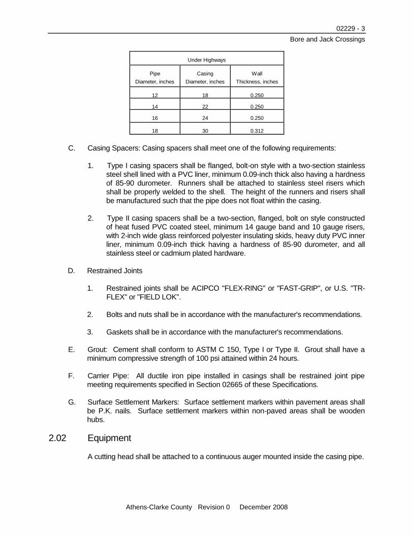
Under Highways
Pipe
Diameter, inches
Casing
Diameter, inches
Wall
Thickness, inches
12 18 0.250
14 22 0.250
16 24 0.250
18 30 0.312
C. Casing Spacers: Casing spacers shall meet one of the following requirements:
1. Type I casing spacers shall be flanged, bolt-on style with a two-section stainless
steel shell lined with a PVC liner, minimum 0.09-inch thick also having a hardness
of 85-90 durometer. Runners shall be attached to stainless steel risers which
shall be properly welded to the shell. The height of the runners and risers shall
be manufactured such that the pipe does not float within the casing.
2. Type II casing spacers shall be a two-section, flanged, bolt on style constructed
of heat fused PVC coated steel, minimum 14 gauge band and 10 gauge risers,
with 2-inch wide glass reinforced polyester insulating skids, heavy duty PVC inner
liner, minimum 0.09-inch thick having a hardness of 85-90 durometer, and all
stainless steel or cadmium plated hardware.
D. Restrained Joints
1. Restrained joints shall be ACIPCO "FLEX-RING" or "FAST-GRIP", or U.S. "TR-
FLEX" or "FIELD LOK".
2. Bolts and nuts shall be in accordance with the manufacturer's recommendations.
3. Gaskets shall be in accordance with the manufacturer's recommendations.
E. Grout: Cement shall conform to ASTM C 150, Type I or Type II. Grout shall have a
minimum compressive strength of 100 psi attained within 24 hours.
F. Carrier Pipe: All ductile iron pipe installed in casings shall be restrained joint pipe
meeting requirements specified in Section 02665 of these Specifications.
G. Surface Settlement Markers: Surface settlement markers within pavement areas shall
be P.K. nails. Surface settlement markers within non-paved areas shall be wooden
hubs.
2.02 Equipment
A cutting head shall be attached to a continuous auger mounted inside the casing pipe.

02229 - 4 Bore and Jack Crossings
Athens-Clarke County Revision 0 December 2008
Part 3 Execution
3.01 General
A. Interpretation of soil investigation reports and data, investigating the site and
determination of the site soil conditions prior to bidding is the sole responsibility of the
Contractor. Any subsurface investigation by the Bidder or Contractor must be
approved by the appropriate authority having jurisdiction over the site.
B. Casing construction shall be performed so as not to interfere with, interrupt or endanger
roadway surface and activity thereon, and minimize subsidence of the surface,
structures, and utilities above and in the vicinity of the casing. Support the ground
continuously in a manner that will prevent loss of ground and keep the perimeters and
face of the casing, passages and shafts stable. The Contractor shall be responsible for
all settlement resulting from casing operations and shall repair and restore damaged
property to its original or better condition.
C. Face Protection: The face of the excavation shall be protected from the collapse of the
soil into the casing.
D. Casing Design: Design of the bore pit and required bearing to resist jacking forces are
the responsibility of the Contractor. The excavation method selected shall be
compatible with expected ground conditions. The lengths of the casing shown on the
Drawings are the minimum lengths required. The length of the casing may be
extended for the convenience of the Contractor, at no additional cost to UGACC. Due
to restrictive right-of-way and construction easements, casing lengths less than the
nominal 20 foot length may be necessary.
E. Highway Crossings
1. The Contractor shall be held responsible and accountable for the coordinating
and scheduling of all construction work within the highway right-of-way and
posting of appropriate permits.
2. Work along or across the highway department rights-of-way shall be subject to
inspection by such highway department.
3. All installations shall be performed to leave free flows in drainage ditches, pipes,
culverts or other surface drainage facilities of the highway, street or its
connections.
4. No excavated material or equipment shall be placed on the pavement or
shoulders of the roadway without the express approval of the highway
department.
5. In no instance will the Contractor be permitted to leave equipment (trucks,
backhoes, etc.) on the pavement or shoulder overnight. Construction materials to
be installed, which are placed on the right-of-way in advance of construction,
02229 - 5 Bore and Jack Crossings
Athens-Clarke County Revision 0 December 2008
shall be placed in such a manner as not to interfere with the safe operation of the
roadway.
6. Where blasting is to be performed on Georgia Department of Transportation
right-of-way, the Contractor shall be responsible for providing UGACC sufficient
information in a timely manner to obtain a blasting permit from the Georgia DOT.
UGACC shall not be responsible for delays in construction due to DOT review
time or for the Contractor’s failure to provide complete and accurate information
required to obtain the permit.
F. Railroad Crossings
1. UGACC will obtain the encroachment permit from the Railroad. However, the
Developer/Contractor shall pay any and all costs and fees. The Contractor shall
secure permission from the Railroad to schedule work so as not to interfere with
the operation of the Railroad.
2. Additional insurance is required for each railroad crossing. The Contractor shall
furnish the Railroad with such additional insurance as may be needed, cost of the
same shall be borne by the Contractor.
3. All work on the Railroad right-of-way, including necessary support of tracks,
safety of operations and other standard and incidental operation procedures may
be under the supervision of the appropriate authorized representative of the
Railroad affected and any decisions of this representative pertaining to
construction and/or operations shall be final and construction must be governed
by such decisions.
4. If, in the opinion of the Railroad, it becomes necessary to provide flagging
protection, watchmen or the performance of any other work in order to keep the
tracks safe for traffic, the Contractor shall coordinate such work and shall
reimburse the Railroad, in cash, for such services, in accordance with accounting
procedures agreed on by the Contractor and affected Railroad before
construction is started.
5. No blasting shall be permitted within the Railroad right-of-way.
3.02 Groundwater Control
A. The Contractor shall control the groundwater throughout the construction of the casing.
B. Methods of dewatering shall be at the option and responsibility of the Contractor.
Maintain close observation to detect settlement or displacement of surface facilities due
to dewatering. Should settlement or displacement be detected, notify UGACC
immediately and take such action as necessary to maintain safe conditions and prevent
damage.
C. When water is encountered, provide and maintain a dewatering system of sufficient
capacity to remove water on a 24 hour basis keeping excavations free of water until the

02229 - 6 Bore and Jack Crossings
Athens-Clarke County Revision 0 December 2008
backfill operation is in progress. Dewatering shall be performed in such a manner that
removal of soil particles is held to a minimum. Dewater into a sediment trap and
comply with requirements specified in Section 02125 of these Specifications.
3.03 Safety
A. Provide all necessary bracing, bulkheads and shields to ensure complete safety to all
traffic, persons and property at all times during the work. Perform the work in such a
manner as to not permanently damage the roadbed or interfere with normal traffic over
it.
B. Observe all applicable requirements of the regulations of the authorities having
jurisdiction over this site. Conduct the operations in such a manner that all work will be
performed below the level of the roadbed.
C. Perform all activities in accordance with the Occupational Safety and Health Act of
1970 (PL-596), as amended, applicable regulations of the Federal Government, OSHA
29CFR 1926 and applicable criteria of ANSI A10.16-81, “Safety Requirements for
Construction of Tunnel Shafts and Caissons”.
D. Bore pits shall not be left unattended unless proper safety barriers are in place.
E. Construction activities adjacent to roadways, including traffic control, shall meet the
requirements of Section 02665, Article 3.02 of these Specifications.
3.04 Surface Settlement Monitoring
A. Provide surface settlement markers for casings 24-inches in diameter and larger.
Place marker as specified and as directed by UGACC. The Contractor shall place
settlement markers outside of pavement area, along the centerline of the casing at 20
foot intervals and offset 10 feet each way from the centerline of the casing. Markers
shall also be placed at each shoulder of the roadway, at each edge of pavement, at the
centerline of the pavement and at 10 and 25 feet in each direction from the centerline
of the casing. Tie settlement markers to bench marks and indices sufficiently removed
as not to be affected by the casing operations.
B. Make observations of surface settlement markers, placed as required herein, at regular
time intervals acceptable to UGACC. In the event settlement or heave on any marker
exceeds 1-inch, the Contractor shall immediately cease work and using a method
approved by UGACC and the authority having jurisdiction over the project site, take
immediate action to restore surface elevations to that existing prior to start of casing
operations.
C. Take readings and permanently record surface elevations prior to start of dewatering
operations and/or shaft excavation. The following schedule shall be used for obtaining
and recording elevation readings: all settlement markers, once a week; all settlement
markers within 50 feet of the casing heading, at the beginning of each day; more
frequently at UGACC's direction if settlement is identified. Make all elevation
measurements to the nearest 0.01 foot.
02229 - 7 Bore and Jack Crossings
Athens-Clarke County Revision 0 December 2008
D. The Contractor shall cooperate fully with jurisdictional personnel. Any settlement shall
be corrected by, and at the expense of, the Contractor.
E. Promptly report any settlement and horizontal movement immediately to UGACC and
take immediate remedial action.
3.05 Casing Installation
A. Shaft
1. Conduct boring and jacking operations from a shaft excavated at one end of the
section to be bored. Where conditions and accessibility are suitable, place the
shaft on the downstream end of the bore.
2. The shaft shall be rectangular and excavated to a width and length required for
ample working space. If necessary, sheet and shore shaft properly on all sides.
Shaft sheeting shall be timber or steel piling of ample strength to safely withstand
all structural loadings of whatever nature due to site and soil conditions. Keep
preparations dry during all operations. Perform pumping operations as
necessary.
3. The bottom of the shaft shall be firm and unyielding to form an adequate
foundation upon which to work. In the event the shaft bottom is not stable,
excavate to such additional depth as required and place a gravel sub-base or a
concrete sub-base if directed by UGACC due to soil conditions.
B. Jacking Rails and Frame
1. Set jacking rails to proper line and grade within the shaft. Secure rails in place to
prevent settlement or movement during operations. The jacking rails shall cradle
and hold the casing pipe on true line and grade during the progress of installing
the casing.
2. Place backing between the heels of jacking rails and the rear of the shaft. The
backing shall be adequate to withstand all jacking forces and loads.
3. The jacking frame shall be of adequate design for the magnitude of the job.
Apply thrust to the end of the pipe in such a manner to impart a uniformly
balanced load to the pipe barrel without damaging the joint ends of the pipe.
C. Boring and jacking of casing pipes shall be accomplished by the dry auger boring
method without jetting, sluicing or wetboring.
D. Auger the hole and jack the casing through the soil simultaneously.
E. Bored installations shall have a bored-hole diameter essentially the same as the
outside diameter of the casing pipe to be installed.

02229 - 8 Bore and Jack Crossings
Athens-Clarke County Revision 0 December 2008
F. Execute boring ahead of the casing pipe with extreme care, commensurate with the
rate of casing pipe penetration. Boring may proceed slightly in advance of the
penetrating pipe and shall be made in such a manner to prevent any voids in the earth
around the outside perimeter of the pipe. Make all investigations and determine if the
soil conditions are such as to require the use of a shield.
G. As the casing is installed, check the horizontal and vertical alignment frequently. Make corrections prior to continuing operation. For casing pipe installations over 100 feet in length, the auger shall be removed and the alignment and grade checked at minimum intervals of 60 feet.
H. Any casing pipe damaged in jacking operations shall be repaired, if approved by
UGACC, or removed and replaced at Contractor's own expense.
I. Lengths of casing pipe, as long as practical, shall be used except as restricted
otherwise. Joints between casing pipe sections shall be butt joints with complete joint
penetration, single groove welds, for the entire joint circumference, in accordance with
AWS recommended procedures. Prior to welding the joints, the Contractor shall
ensure that both ends of the casing sections being welded are square.
J. The Contractor shall prepare a contingency plan which will allow the use of a casing
lubricant, such as bentonite, in the event excessive frictional forces jeopardize the
successful completion of the casing installation.
K. Once the jacking procedure has begun, it should be continued without stopping until
completed, subject to weather and conditions beyond the control of the Contractor.
L. Care shall be taken to ensure that casing pipe installed by boring and jacking method
will be at the proper alignment and grade.
M. The Contractor shall maintain and operate pumps and other necessary drainage
system equipment to keep work dewatered at all times.
N. Adequate sheeting, shoring and bracing for embankments, operating pits and other
appurtenances shall be placed and maintained to ensure that work proceeds safely
and expeditiously. Upon completion of the required work, the sheeting, shoring and
bracing shall be left in place, cut off or removed, as designated by UGACC.
O. Trench excavation, all classes and type of excavation, the removal of rock, muck,
debris, the excavation of all working pits and backfill requirements of Section 02225 are
included under this Section.
P. All surplus material shall be removed from the right-of-way and the excavation finished
flush with the surrounding ground.
Q. Grout backfill shall be used for unused holes or abandoned pipes.
R. Any replacement of carrier pipe in an existing casing shall be considered a new
installation, subject to the applicable requirements of these Specifications.

02229 - 9 Bore and Jack Crossings
Athens-Clarke County Revision 0 December 2008
3.06 Free Boring
A. Where the Drawings indicate a pipeline is to be installed by boring without casing, the
Contractor shall construct the crossing by the free bore method. The free bore method
shall be accomplished by the dry auger boring method without jetting, sluicing, or wet
boring.
B. The diameter of the free bore shall not exceed the pipe bell outside diameter or the
pipe barrel outside diameter plus 1-inch, whichever is greater.
C. Free boring, where indicated on the Drawings, is to be performed at the Contractor's
option. The Contractor may choose to construct the crossing by the conventional bore
and jack casing methodology.
D. The Contractor shall be responsible for any settlement of the roadway caused by the
free bore construction activities.
3.07 Ventilation and Air Quality
Provide, operate and maintain for the duration of casing project a ventilation system to
meet safety and OSHA requirements.
3.08 Rock Excavation
A. In the event that rock is encountered during the installation of the casing pipe which, in
the opinion of UGACC, cannot be removed through the casing, UGACC may authorize
the Contractor to complete the crossing by a method established in a change order.
B. At the Contractor's option, the Contractor may continue to install the casing and remove
the rock through the casing.
3.09 Installation of Pipe
A. After construction of the casing is complete, and has been accepted by UGACC, install
the pipeline in accordance with the Drawings and Specifications.
B. Check the alignment and grade of the casing and prepare a plan to set the pipe at
proper alignment, grade and elevation, without any sags or high spots.
C. The carrier pipe shall be held in the casing pipe by one of the following methods:
1. The carrier pipe shall be held in the casing pipe by the use of hardwood blocks
spaced radially around the pipe and secured together so that they remain firmly
in place. The spacing of such blocks longitudinally in the casing pipe shall not be
greater than 10 feet.

02229 - 10 Bore and Jack Crossings
Athens-Clarke County Revision 0 December 2008
2. The pipe shall be supported within the casing by use of casing spacers sized to
limit radial movement to a maximum of 1-inch. Provide a minimum of two casing
spacers per nominal length of pipe. Casing spacers shall be attached to the pipe
at maximum 9 to 10 foot intervals.
D. Close the ends of the casing with 4-inch brick walls.
3.10 Sheeting Removal
Remove sheeting used for shoring from the shaft and off the job site. The removal of
sheeting, shoring and bracing shall be done in such a manner as not to endanger or
damage either new or existing structures, private or public properties and also to avoid
cave-ins or sliding in the banks.
END OF SECTION

Section 02575 Removing and Replacing Pavement
Athens-Clarke County Revision 0 December 2008
Part 1 General
1.01 Scope
A. The work to be performed under this Section shall consist of removing and replacing
existing pavement, sidewalks and curbs in paved areas where such have been
removed for construction of utilities and appurtenances.
B. Existing pavement, sidewalks and curbs shall be replaced to the current Unified
Government of Athens-Clarke County (UGACC) standards or to match existing,
whichever is more stringent.
1.02 Submittals
If required by UGACC, provide certificates stating that materials supplied comply with
Specifications. Certificates shall be signed by the asphalt producer and the Contractor.
1.03 Conditions
A. Weather Limitations
1. Apply bituminous tack coat only when the ambient temperature in the shade has
been at least 50 degrees F for 12 hours immediately prior to application.
2. Do not conduct paving operations when surface is wet or contains excess of
moisture which would prevent uniform distribution and required penetration.
3. Construct asphaltic courses only when atmospheric temperature in the shade is
above 40 degrees F, when the underlying base is dry and when weather is not
rainy.
4. Place base course when air temperature is above 35 degrees F and rising.
B. Grade Control: Establish and maintain the required lines and grades for each course
during construction operations.
Part 2 Products
2.01 Materials and Construction
A. Graded Aggregate Base Course: Graded aggregate base course shall be of uniform
quality throughout and shall meet the requirements of Section 815.01 of the Georgia
Department of Transportation Standard Specifications.

02575 - 2 Removing and Replacing Pavement
Athens-Clarke County Revision 0 December 2008
B. Black Base: Black base course shall be of uniform quality throughout and shall
conform to the requirements of Section 828 of the Georgia Department of
Transportation Standard Specifications.
C. Bituminous Tack Coat: The bituminous tack coat shall conform to the requirements of
Section 400 of the Georgia Department of Transportation Standard Specifications.
D. Surface Course: The surface course for all asphaltic concrete pavement shall conform
to the requirements of Section 400, Type “F” (Super Pave 9.5 mm) of the Georgia
Department of Transportation Standard Specifications unless other types are noted on
the Drawings or required by UGACC.
E. Concrete: Provide concrete and reinforcing for concrete pavement or base courses in
accordance with the requirements of the Georgia Department of Transportation
Standard Specifications, Section 430. Concrete shall be of the strength classifications
shown on the Drawings.
F. Special Surfaces: Where driveways or roadways are disturbed or damaged which are
constructed of specialty type surfaces, e.g., brick or stone, these driveways and
roadways shall be restored utilizing similar, if not original, materials. Where the nature
of these surfaces dictate, a specialty contractor shall be used to restore the surfaces to
their previous or better condition. Special surfaces shall be removed and replaced to
the limits to which they were disturbed.
2.02 Types of Pavements
A. General: All existing pavement removed, destroyed or damaged by construction shall
be replaced with the same type and thickness of pavement as that existing prior to
construction, unless otherwise directed by UGACC. Materials, equipment and
construction methods used for paving work shall conform to the Georgia Department of
Transportation specifications applicable to the particular type required for replacement,
repair or new pavements.
B. Aggregate Base: Aggregate base shall be constructed in accordance with the
requirements of Section 310 of the Georgia Department of Transportation Standard
Specifications. The maximum thickness to be laid in a single course shall be 6-inches
compacted. If the design thickness of the base is more than 6-inches, it shall be
constructed in two or more courses of approximate equal thickness. After the material
placed has been shaped to line, grade and cross-section, it shall be rolled until the
course has been uniformly compacted to at least 100 percent of the maximum dry
density when Group 2 aggregate is used, or to at least 98 percent of maximum dry
density when Group 1 aggregate is used.
C. Concrete Pavement: Concrete pavement or base courses shall be replaced with
concrete. The surface finish of the replaced concrete pavement shall conform to that of
the existing pavement. The surface of the replaced concrete base course shall be left
rough. The slab depth shall be equivalent to the existing concrete pavement or base
course, but in no case less than 6-inches thick. Transverse and longitudinal joints
removed from concrete pavement shall be replaced at the same locations and to the
02575 - 3 Removing and Replacing Pavement
Athens-Clarke County Revision 0 December 2008
same types and dimensions as those removed. Concrete pavements or concrete base
courses shall be reinforced.
D. Asphaltic Concrete Base, Bituminous Tack Coat and Surface Course: Asphaltic
concrete base, tack coat and surface course construction shall conform to Georgia
Department of Transportation Standard Specifications, Section 400. The pavement
mixture shall not be spread until the designated surface has been previously cleaned
and prepared, is intact, firm, properly cured, dry and the tack coat has been applied.
Apply and compact the base in maximum layer thickness by asphalt spreader
equipment of design and operation approved by UGACC. After compaction, the black
base shall be smooth and true to established profiles and sections. Apply and compact
the surface course in a manner approved by UGACC. Immediately correct any high,
low or defective areas by cutting out the course, replacing with fresh hot mix, and
immediately compacting to conform and thoroughly bond to the surrounding area.
E. Surface Treatment Pavement: Bituminous penetration surface treatment pavement
shall be replaced with a minimum thickness of 1-inch conforming to Section 424,
Georgia Department of Transportation Standard Specifications.
F. Gravel Surfaces: Existing gravel road, drive and parking area replacement shall meet
the requirements of graded aggregate base course. This surfacing may be authorized
by UGACC as a temporary surface for paved streets until replacement of hard surfaced
pavement is authorized.
G. Temporary Measures: During the time period between pavement removal and
complete replacement of permanent pavement, maintain highways, streets and
roadways by the use of steel running plates anchored to prevent movement. The
backfill above the pipe shall be compacted, as specified in Section 02225 of these
Specifications, up to the existing pavement surface to provide support for the steel
running plates. All pavement shall be replaced within seven calendar days of its
removal.
Part 3 Execution
3.01 Pavement Replacement
A. See detail G-1 for pavement removal and replacement requirements associated with
trenching.
B. Resurfacing Requirements: where longitudinal pavement cuts exceed 150 feet in
length, the cut shall be patched in accordance with these specifications and the entire
roadway width shall be resurfaced with a minimum of 1-1/2” of Type “F” (Super Pave
9.5 mm) asphalt for the entire length of the cut plus 20 feet in each direction. All striping
and pavement markings shall be replaced to pre-existing conditions.
C. “Graded Aggregate” pavement repair shall be used only to replace existing gravel
or crushed stone surfaces. Thickness of replacement stone shall be a minimum of
4 inches, regardless of thickness of existing stone.

02575 - 4 Removing and Replacing Pavement
Athens-Clarke County Revision 0 December 2008
3.02 Removing Pavement
A. General: Remove existing pavement as necessary for installing the pipe line and
appurtenances.
B. Marking: Before removing any pavement, mark the pavement neatly paralleling pipe
lines and existing street lines. Space the marks the width of the trench.
C. Breaking: Break asphalt pavement and concrete pavement along the marks by cutting
through with a rotary saw.
D. Machine Pulling: Do not pull pavement with machines until the pavement is completely
broken and separated from pavement to remain.
E. Damage to Adjacent Pavement: Do not disturb or damage the adjacent pavement. If
the adjacent pavement is disturbed or damaged, remove and replace the damaged
pavement.
F. Sidewalk: Remove and replace any sidewalks disturbed by construction for their full
width and to the nearest undisturbed joint.
G. Curbs: Tunnel under or remove and replace any curb disturbed by construction to the
nearest undisturbed joint.
3.03 Replacing Pavement
A. Preparation of Subgrade: Upon completion of backfilling and compaction of the
backfill, arrange to have the compaction tested by an independent testing laboratory
approved by UGACC. After compaction testing has been satisfactorily completed,
replace all pavements, sidewalks and curbs removed.
1. The existing street pavement or surface shall be removed along the lines of the
work for the allowable width specified for the trench or structure. After the
installation of the sewerage or water works facilities and after the backfill has
been compacted suitably, the additional width of pavement to be removed, as
shown on the Drawings, shall be done immediately prior to replacing the
pavement.
2. Trench backfill shall be compacted for the full depth of the trench as specified in
Section 02225 of these Specifications.
3. Temporary trench backfill along streets and driveways shall include 6-inches of
crushed stone or cherty clay as a temporary surfacing of the trenches. This
temporary surface shall be maintained carefully at grade and dust-free by the
Contractor until the backfill of the trench has thoroughly compacted in the opinion
of UGACC and permission is granted to replace the street pavement.
4. When temporary crushed stone or chert surface is considered by UGACC to be
sufficient surface for gravel pavement, the surface shall be graded smooth and to
02575 - 5 Removing and Replacing Pavement
Athens-Clarke County Revision 0 December 2008
an elevation that will make the final permanent surfacing level with the adjacent
surfacing that was undisturbed.
B. Pavement Replacement
1. Prior to replacing pavement, make a final cut in concrete pavement 12-inches
back from the edge of the damaged pavement with a concrete saw. Remove
asphalt pavement 12-inches back from the edge of the damaged pavement
using pavement shearing equipment, jackhammers or other suitable tools.
Pavement cuts shall be parallel or perpendicular to the road centerline as much
as practical. On parallel installations the final cut shall be long and straight and
consistent.
2. Replace all street and roadway pavement as shown on the Drawings. Replace
driveways, sidewalks and curbs with the same material, to nearest existing
undisturbed construction joint and to the same dimensions as those existing.
3. If the temporary crushed stone or chert surface is to be replaced, the top
6-inches shall be removed and the crushed stone surfacing for unpaved streets
or the base for the bituminous surface shall be placed.
4. Following this preparation, the chert or crushed stone base shall be primed with a
suitable bituminous material and surfaced with the proper type of bituminous
surface treatment.
5. Where the paved surface is to be replaced with asphaltic concrete pavement,
concrete pavement or with a concrete base and a surface course, the temporary
chert or crushed stone surface and any necessary backfill material, additional
existing paving and new excavation shall be removed to the depth and width
shown on the Drawings. All edges of the existing pavement shall be cut to a
straight, vertical edge. Care shall be used to get a smooth joint between the old
and new pavement and to produce an even surface on the completed street.
Concrete base slabs and crushed stone bases, if required, shall be placed and
allowed to cure for three days before bituminous concrete surface courses are
applied. Expansion joints, where applicable, shall be replaced in a manner equal
to the original joint.
6. Where driveways or roadways, constructed of specialty type surfaces, e.g., brick
or stone are disturbed or damaged, these driveways and roadways shall be
restored utilizing similar materials. Where the nature of these surfaces dictate, a
specialty contractor shall be used to restore the surfaces to their previous or
better condition. Special surfaces shall be removed and replaced to the limits to
which they were disturbed.
C. Pavement Resurfacing
1. Certain areas to be resurfaced are specified or noted on the Drawings. Where
pavement to be resurfaced has been damaged with potholes, the Contractor
shall remove all existing loose pavement material and fill the hole with black base,

02575 - 6 Removing and Replacing Pavement
Athens-Clarke County Revision 0 December 2008
as specified, to the level of the existing pavement. After all pipe line installations
are complete and existing pavement has been removed and replaced along the
trench route, apply tack coat and surface course as specified.
2. Resurfacing limits shall be perpendicular to the road centerline. The limits of
resurfacing shall be 10 feet beyond the edge of the pavement replacement on
the main road being resurfaced, and to the point of tangency of the pavement on
the side streets.
3. Pavement resurfacing shall be performed by a contractor certified by the Georgia
DOT.
D. Pavement Striping: Pavement striping removed or paved over shall be replaced with
the same type, dimension and material as original unless directed otherwise by
UGACC.
3.04 Sidewalk and Curb Replacement
A. Construction
1. All concrete sidewalks and curbs shall be replaced with concrete.
2. Preformed joints shall be 1/2-inch thick, conforming to the latest edition of
AASHTO M 59 for sidewalks and AASHTO M 123 for curbs.
3. Forms for sidewalks shall be of wood or metal, shall be straight and free from
warp, and shall be of sufficient strength, when in place, to hold the concrete true
to line and grade without springing or distorting.
4. Forms for curbs shall be metal and of an approved section. They shall be
straight and free from distortions, showing no vertical variation greater than
1/8-inch in 10 feet and no lateral variation greater than 1/4-inch in 10 feet from
the true plain surface on the vertical face of the form. Forms shall be of the full
depth of the structure and constructed such to permit the inside forms to be
securely fastened to the outside forms.
5. Securely hold forms in place true to the lines and grades indicated on the
Drawings.
6. Wood forms may be used on sharp turns and for special sections, as approved
by UGACC. Where wooden forms are used, they shall be free from warp and
shall be the nominal depth of the structure.
7. All mortar and dirt shall be removed from forms and all forms shall be thoroughly
oiled or wetted before any concrete is deposited.
B. When a section is removed, the existing sidewalk or curb shall be cut to a neat line,
perpendicular to both the centerline and the surface of the concrete slab. Existing
concrete shall be cut along the nearest existing construction joints.

02575 - 7 Removing and Replacing Pavement
Athens-Clarke County Revision 0 December 2008
C. Existing concrete sidewalks and curbs that have been cut and removed for construction
purposes shall be replaced with the same width and surface as the portion removed.
Sidewalks shall have a minimum uniform thickness of 4-inches. The new work shall be
neatly jointed to the existing concrete so that the surface of the new work shall form an
even, unbroken plane with the existing surfaces.
D. The subgrade shall be formed by excavating to a depth equal to the thickness of the
concrete, plus 2-inches. Subgrade shall be of such width as to permit the proper
installation and bracing of the forms. Subgrades shall be compacted by hand tamping
or rolling. Soft, yielding or unstable material shall be removed and backfilled with
satisfactory material. Place 2-inches of porous crushed stone under all sidewalks and
curbs and compacted thoroughly, then finish to a smooth, unyielding surface at proper
line, grade and cross section.
E. Joint for Curbs
1. Joints shall be constructed to match existing and as specified. Construct joints
true to line with their faces perpendicular to the surface of the structure and within
1/4-inch of their designated position.
2. Thoroughly spade and compact the concrete at the faces of all joints filling all
voids.
3. Install expansion joint materials at the point of curve at all street returns. Install
expansion joint material behind the curb at abutment to sidewalks and adjacent
structures.
4. Place contraction joints every 10 feet along the length of the curbs and gutters.
Form contraction joints using steel templates or division plates which conform to
the cross section of the structure. Leave the templates in place until the concrete
has set sufficiently to hold its shape, but remove them while the forms are still in
place. Contraction joint templates or plates shall not extend below the top of the
steel reinforcement or they shall be notched to permit the reinforcement to be
continuous through the joint. Contraction joints shall be a minimum of
1-1/2-inches deep.
F. Expansion joints shall be required to replace any removed expansion joints or in new
construction wherever shown on the Drawings. Expansion joints shall be true and
even, shall present a satisfactory appearance, and shall extend to within 1/2-inch of the
top of finished concrete surface.
G. Finishing
1. Strike off the surface with a template and finish the surface with a wood float
using heavy pressure, after which, contraction joints shall be made and the
surface finished with a wood float or steel trowel.

02575 - 8 Removing and Replacing Pavement
Athens-Clarke County Revision 0 December 2008
2. Finish the face of the curbs at the top and bottom with an approved finishing tool
of the radius to match existing.
3. Finish edges with an approved finishing tool.
4. Provide a final broom finish by lightly combing with a stiff broom after troweling is
complete.
5. The finished surface shall not vary more than 1/8-inch in 10 feet from the
established grade.
H. Driveway and Sidewalk Ramp Openings
1. Provide driveway openings of the widths and at the locations indicated on the
Drawings and as directed by UGACC.
2. Provide sidewalk ramp openings to match existing in conformance with the
applicable regulations and as directed by UGACC.
I. Concrete shall be suitably protected from freezing and excessive heat. It shall be kept
covered with burlap or other suitable material and kept wet until cured. Provide
necessary barricades to protect the work. All damage caused by people, vehicles,
animals, rain, the Contractor's operations and the like shall be repaired by the
Contractor.
3.05 Maintenance
The Contractor shall maintain the surfaces of roadways built and pavements replaced
until the acceptance of the Project. Maintenance shall include replacement, scraping,
reshaping, wetting and rerolling as necessary to prevent raveling of the road material,
the preservation of reasonably smooth surfaces and the repair of damaged or
unsatisfactory surfaces, to the satisfaction of UGACC. Maintenance shall include
sprinkling as may be necessary to abate dust from the gravel surfaces.
3.06 Supervision and Approval
A. Pavement restoration shall meet the requirements of the regulatory agency responsible
for the pavement. Obtain agency approval of pavement restorations before requesting
final payment.
B. Obtain UGACC's approval of restoration of pavement, such as private roads and drives
that are not the responsibility of a regulatory agency.
C. Complete pavement restoration as soon as possible after backfilling.
D. Failure of Pavement: Should any pavement restoration or repairs fail or settle during
the life of the Contract, including the bonded period, promptly restore or repair defects.

02575 - 9 Removing and Replacing Pavement
Athens-Clarke County Revision 0 December 2008
3.07 Cleaning
The Contractor shall remove all surplus excavation materials and debris from the street
surfaces and rights-of-way and shall restore street, roadway or sidewalk surfacing to its
original condition.
END OF SECTION
Section 02665 Water Mains and Accessories
Athens-Clarke County Revision 0 December 2008
Part 1 General
1.01 Scope
A. This Section described products to be incorporated into the water mains and
requirements for the installation and use of these items. Furnish all products and
perform all labor necessary to fulfill the requirements of these Specifications.
B. Supply all products and perform all work in accordance with applicable American
Society for Testing and Material (ASTM), American Water Works Association (AWWA),
American National Standards Institute (ANSI), or other recognized standards. Latest
revisions of all standards are applicable
1.02 Qualifications
All products and materials provided or installed on any project must be pre-approved
and included in the approved manufacturer’s list for water or wastewater system
construction (see Appendix A).
1.03 Submittals
If required by The Unified Government of Athens- Clarke County (UGACC), complete
product data and engineering data, including shop drawings, shall be submitted to
UGACC for review.
1.04 Transportation and Handling
A. Unloading: Furnish equipment and facilities for unloading, handling, distributing, and
storing pipe, fittings, valves, and accessories. Make equipment available at all times for
use in unloading. Do not drop or dump materials. Any materials dropped or dumped
will be subject to rejection without additional justification. Pipe handling on skids shall
not be rolled or skidded against the pipe on the ground.
B. Handling: Handle pipe, fittings, valves, and accessories carefully to prevent shock or
damage. Handle pipe by rolling on skids, forklift, or front end loader. Do not use
material damaged in handling. Slings, hooks, or pipe tongs shall be padded and used
in such a manner as to prevent damage to the exterior coatings or internal lining of the
pipe. Do not use chains in handling pipe, fittings, and appurtenances.
1.05 Storage and Protection
A. Store all pipe which cannot be distributed along the route. Make arrangements for the
use of suitable storage areas.
B. Stored materials shall be kept safe from damage. The interior of all pipe, fittings, and
other appurtenances shall be kept free from dirt or foreign matter at all times. Valves

02665 - 2 Water Mains and Accessories
Athens-Clarke County Revision 0 December 2008
and hydrants shall be drained and stored in a manner that will protect them from
damage by freezing.
C. Pipe shall not be stacked higher than the limits recommended by the manufacturer.
The bottom tier shall be kept off the ground on timbers, rails, or concrete. Pipe in tiers
shall be alternated: bell, plain end; bell, plain end. At least two rows of timbers shall be
placed between tiers and chocks, affixed to each other in order to prevent movement.
The timbers shall be large enough to prevent contact between the pipe in adjacent
tiers.
D. Store joint gaskets in a cool location, out of direct sunlight. Gaskets shall not come in
contact with petroleum products. Gaskets shall be used on a first-in, first-out basis.
E. Mechanical-joint bolts shall be handled and stored in such a manner that will ensure
proper use with respect to types and sizes.
1.06 Quality Assurance
Product manufacturers shall provide written certification to UGACC that all products
furnished comply with all applicable requirements of these Specifications.
Part 2 Products
2.01 Ductile Iron Pipe
A. Ductile iron pipe shall be manufactured in accordance with AWWA C151. All pipe,
except specials, shall be furnished in nominal lengths of 18 to 20 feet. Sizes will be as
shown on the Drawings. All pipe shall have a minimum pressure rating of 350 psi and
corresponding minimum wall thickness, unless otherwise specified or shown on the
drawings.
B. Flanged pipe minimum wall thickness shall be equal to Special Thickness Class 53.
Flanges shall be furnished by the pipe manufacturer.
C. Pipe and fittings shall be cement lined in accordance with AWWA C104. A seal coat
over the cement lining is not required. Pipe and fittings shall be furnished with a
bituminous outside coating.
D. Fittings shall be ductile iron and shall conform to AWWA C110 or AWWA C153 with a
minimum rated working pressure of 250 psi.
E. Joints
1. Unless shown or specified otherwise, joints shall be push-on or restrained joint
type for pipe and standard mechanical, push-on, or restrained joints for fittings.
Push-on and mechanical joints shall conform to AWWA C111.

02665 - 3 Water Mains and Accessories
Athens-Clarke County Revision 0 December 2008
2. The only acceptable restrained joint systems are identified in the table below. No
field welding of restrained joint pipe will be allowed.
Size ACIPCO U.S. Pipe Generic1
4-12 Fast-Grip
Flex Ring
Field Lok
TR Flex
MJ with Retainer
Gland
16-18 Fast-Grip
Flex Ring
Field Lok
TR Flex
MJ with Retainer
Gland
1Fittings and valves only, and only where specifically allowed.
3. Restrained joint pipe (RJP) on supports shall have bolted joints and shall be
specifically designed for clear spans of at least 36 feet.
4. Flanged joints shall meet the requirements of ANSI B16.1, Class 125.
F. Provide the appropriate gaskets for mechanical and flange joints. Gaskets for flange
joints shall be made of 18-inch thick, cloth reinforced rubber; gaskets may be ring type
or full face type.
G. Bolts and Nuts
1. Provide the necessary bolts for connections. All bolts and nuts shall be threaded
in accordance with ANSI B1.1, Coarse Thread Series, Class 2A external and 2B
internal fit. All bolts and nuts shall be made in the U.S.A.
2. Bolts and nuts for mechanical joints shall be Tee Head Bolts and nuts of high
strength low-alloy steel in accordance with ASTM A 242 to the dimensions shown
in AWWA C111/ANSI A21.11.
3. Flanged joints shall be bolted with through stud or tap bolts of required size as
directed. Bolt length and diameter shall conform to ANSI/AWWA C115 for Class
125 flanges shown in ANSI/ASME B16.1.
4. Bolts for exposed service shall be zinc plated, cold pressed, steel machine bolts
conforming to ASTM A 307, Grade B. Nuts for exposed service shall be zinc
plated, heavy hex conforming to ASTM A 563. Zinc plating shall conform to
ASTM B 633, Type II.
5. Bolts for submerged service shall be stainless steel machine bolts conforming to
ASTM A 193, Grade B8. Nuts shall be heavy hex, stainless steel conforming to
ASTM A 194, Grade 8.
H. Mechanical joint glands shall be ductile iron.
I. Welded Outlet: Welded outlets may be provided in lieu of tees or saddles. The pipe
joint on the outlet pipe shall meet the joint requirements specified above. The
minimum pipe wall thickness of the parent pipe and the outlet pipe shall be Special
Thickness Class 53. The welded outlet shall be rated for 250 psi working pressure.
02665 - 4 Water Mains and Accessories
Athens-Clarke County Revision 0 December 2008
Each welded outlet shall be hydrostatically tested at 500 psi. The welded outlet shall
be fabricated by the manufacturer of the parent pipe.
J. Ductile iron pipe shall be encased with polyethylene film where shown on the Drawings
or Specified. Polyethylene film shall be in accordance with AWWA C105.
K. Thrust collars shall be welded-on ductile iron body type designed to withstand thrust
due to 250 psi internal pressure on a dead end.
L. Acceptance will be on the basis of Engineer’s inspection and the manufacturer’s
written certification that the pipe was manufactured and tested in accordance with the
applicable standards.
2.02 Copper Pipe
A. Pipe shall be hard drawn copper tubing, ASTM B 88, Type K. Fittings shall be flare
type. No sweat or compression joints shall be used.
B. Where required, flare to screw adapters shall be cast bronze ANSI B16.18. Unions
shall be cast bronze.
2.03 Piping Appurtenances
A. Retainer Glands
1. Retainer glands shall be provided with wedge type set screws and inherent
torque limiting devices, including twist-off nuts. Retainer glands shall have a rated
working pressure of 350 psi through 16-inch size, and 250 psi in larger sizes.
2. Retainer glands shall be provided at all mechanical joints, including fittings,
valves, hydrants, and other locations as shown on the Drawings.
B. Hydrant Tees: Hydrant tees shall be equal to ACIPCO A10180 or U.S. Pipe U-592.
C. Anchor Couplings: Lengths and sizes shall be as shown on the Drawings. Anchor
couplings shall be as shown on the Drawings. Anchor couplings shall be equal to
ACIPCO A10895 or U.S. Pipe U-591.
D. Hydrant Connector Pipe: The connector pipe shall be ductile iron meeting the
requirements of AWWA C153. Connector pipe shall be of the 24-inch offset design so
that the hydrant can be adjusted to ensure placement at the proper grade. Connector
pipe shall have an anchoring feature at both ends so that when used with mechanical
joint split glands a restrained joint is provided. The connector pipe shall be cement-
lined in accordance with AWWA C104.
E. Tapping Saddles: Tapping saddles shall be ductile iron body type with O-ring gasket
and alloy steel straps. Connection shall be flanged or mechanical joint as detailed on
the Drawings. Tapping saddles shall be equal to ACIPCO A-10920 and ACIPCO A-
30920.

02665 - 5 Water Mains and Accessories
Athens-Clarke County Revision 0 December 2008
2.04 Gate Valves (GV)
A. Gate valves shall be resilient-seated type conforming to the requirements of AWWA
C509 or AWWA C515.
B. Valves through 12-inches in diameter shall have a minimum rated working pressure of
200 psi. 16-inch and 18-inch valves shall have a minimum rated working pressure of
150 psi.
C. Valves less than 4-inches in diameter shall have threaded ends. Larger valves shall
be mechanical joint unless shown otherwise on the Drawings.
D. Valves shall be non-rising stem type with a 2-inch square wrench nut, and shall open
left. The manufacturer shall provide an affidavit of compliance with the applicable
AWWA standards.
E. All internal ferrous surfaces shall be coated with epoxy to a minimum thickness of 4
mils. The epoxy shall be non-toxic, impart no taste to the water and shall conform to
AWWA C550.
F. All seals between valve parts, such as body and bonnet cover, shall be flat gaskets or
O-rings.
G. Valve disks shall be made of cast or ductile iron having a vulcanized, synthetic rubber
coating.
2.05 Butterfly Valves (BV)
A. Unless indicated on the Drawings to be 250 pound valves, butterfly valves shall be
resilient seated, short body design, and shall be designed, manufactured, and tested
in accordance with all requirements of AWWA C504 for Class 150B.
B. Where butterfly valves are indicated on the Drawings to be 250 pound valves, butterfly
valves shall be resilient seated, short body design, and shall be designed,
manufactured, and tested in accordance with all requirements of AWWA C504, and as
modified below. Valves shall be designed for a rated working pressure of 250 psi.
Class B, AWWA C504 Section 5.2 testing requirements are modified as follows:
1. The leakage test shall be performed at a pressure of 250 psi.
2. The hydrostatic test shall be performed at a pressure of 500 psi.
3. Proof of design tests shall be performed and certification of such proof of design
test shall be provided to the Engineer.
C. 150 Pound Valves: Valve bodies shall be ductile iron conforming to ASTM A 536,
Grade 65-45-12 or ASTM A 126, Grade B cast iron. Shafts shall be ASTM A276, Type
304 stainless steel, machined and polished. Valve discs shall be ductile iron, ASTM A

02665 - 6 Water Mains and Accessories
Athens-Clarke County Revision 0 December 2008
536, Grade 65-45-12 or ASTM A 126, Grade B cast iron. The valve shall have a
resilient seat.
D. 250 Pound Valves: Valve bodies shall be ductile iron conforming to ASTM A 536,
Grade 65-45-12 or ASTM A 126, Grade B cast iron. Shafts and shaft hardware shall
be ASTM A 564, Type 630 stainless steel, machined and polished. Valve discs shall
be ductile iron, ASTM A 536, Grade 65-45-12. The resilient seat shall be located either
on the valve disc or in the valve body and shall be fully field adjustable and field
replaceable.
E. Valves shall be installed with the valve shafts horizontal. Valves and actuators shall
have seals on all shafts and gaskets on valve actuator covers to prevent the entry of
water. Actuator mounting brackets shall be totally enclosed and shall have gasket
seals.
F. Actuators
1. Valves shall be equipped with traveling nut, self-locking type actuators designed,
manufactured, and tested in accordance with AWWA C504. Actuators shall be
capable of holding the disc in any position between full open and full closed
without any movement or fluttering of the disc.
2. Actuators shall be furnished with fully adjustable mechanical stop-limiting devices.
Actuators that utilize the sides of the actuator housing to limit disc travel are
unacceptable.
3. Valve actuators shall be capable of withstanding a minimum of 450 foot pounds
of input torque in either the open or closed position without damage.
G. Operators: Valves for buried service shall have a nut type operator and shall be
equipped with a valve box and stem extension, as required.
H. Valve ends shall be mechanical joint type, except where flanged or restrained joint
ends are shown. Flange joints shall meet the requirements of ANSI B16.1, Class 125.
2.06 Fire Hydrants (FH)
A. All fire hydrants shall conform to the requirements of AWWA C502 for 150 psi working
pressure. Hydrants shall be the compression type, closing with line pressure. The
valve opening shall not be less than 5-1/4-inches.
B. In the event of a traffic accident, the hydrant barrel shall break away from the
standpipe at a point above grade and in a manner which will prevent damage to the
barrel and stem, preclude opening of the valve, and permit rapid and inexpensive
restoration without digging or cutting off the water.
C. The means for attaching the barrel to the standpipe shall permit facing the hydrant a
minimum of eight different directions.

02665 - 7 Water Mains and Accessories
Athens-Clarke County Revision 0 December 2008
D. Hydrants shall be fully bronze mounted with all working parts of bronze. Valve seat
ring shall be bronze and shall screw into a bronze retainer.
E. All working parts, including the seat ring shall be removable through the top without
disturbing the barrel of the hydrant.
F. The operating nut shall match those on the existing hydrants. The operating threads
shall be totally enclosed in an operating chamber, separated from the hydrant barrel by
a rubber O-ring stem seal and lubricated by a grease or an oil reservoir.
G. Hydrant shall be a non-freezing design and be provided with a simple, positive, and
automatic drain which shall be fully closed whenever the main valve is opened.
H. Hose and pumper connections shall be breech-locked, pinned, or threaded and pinned
to seal them into the hydrant barrel. Each hydrant shall have two 2-1/2-inch hose
connections and one 4-1/2-inch pumper connection, all with National Standard threads
and each quipped with cap and non-kinking chain.
I. Hydrants shall be furnished with a mechanical joint connection to the spigot of the 6-
inch hydrant lead.
J. Minimum depth of bury shall be 4.5 feet. Provide extension section where necessary
for proper vertical installation and in accordance with manufacturer’s
recommendations.
K. Hydrant shoe shall incorporate a fabric and steel reinforced elastomeric flapper check
valve, allowing normal operation of and access to the hydrant main valve. Check valve
shall provide non-slam, quiet operation and bubble-tight shut off. The valve body shall
be constructed of ductile iron ASTM A-536 Grade 65-45-12 with a flow area equal to
the nominal pipe inside diameter throughout the valve. Seat shall be constructed on a
45 degree angle to reduce disc travel. The seat and internal body shall be fully coated
with a two part thermosetting epoxy. The bonnet shall have stainless steel bolts and
provide for easy inspection of the flexible disc and seat. Check valve can either be
manufactured directly onto hydrant shoe or can be a separate valve that connects
directly to the shoe with a mechanical joint connection. If a separate check valve, it
shall be of the anchoring type (male mechanical joint on one end and male mechanical
joint with swivel gland on the other end) with no internal moving parts except for the
resilient disc. Valve shall be rated to 250 psi.
L. Hydrants shall be furnished with a security device manufactured of 14 gauge 304
stainless steel straps with a stainless steel barrel lock which has a key that is uniquely
coded for the Owner and strictly controlled by the manufacturer. All locks shall be
keyed similarly, and one key per hydrant shall be provided to the Owner.
M. All outside surfaces of the barrel above grade shall be painted with Sherwin Williams
KEM 400, silver in color.

02665 - 8 Water Mains and Accessories
Athens-Clarke County Revision 0 December 2008
2.07 Valve Boxes (VB) and Extension Stems
A. All valve boxes shall be equipped with valve boxes. The valve boxes shall be cast iron
two-piece screw type with drop covers. Valve boxes shall have a 5.25-inch inside
diameter. Valve box covers shall weigh a minimum of 13 pounds. The valve boxes
shall be adjustable to 6-inches up or down from the nominal required cover over the
pipe. Valve boxes shall be of sufficient length that bottom flange of the lower belled
portion of the box is below the valve operating nut. Ductile or cast iron extensions shall
be provided as necessary. Covers shall have “WATER VALVE” or “WATER” cast into
them. Valve boxes shall be manufactured in the United States.
B. All valves shall be furnished with extension stems if operating nut is greater than four
feet deep, to bring the operating nut to within 24-inches of the top of the valve box.
Connection to the valve shall be with a wrench nut coupling and a set screw to secure
the coupling to the valve’s operating nut. The coupling and square wrench nut shall be
welded to the extension stem.
2.08 Valve Markers (VM)
The Contractor shall provide a concrete valve marker as detailed on the Drawings for
each valve installed. Valve markers shall be stamped “WATER”.
2.09 Tapping Sleeves and Valves (TS&V)
Tapping sleeves shall be cast or ductile iron of the split-sleeve, mechanical joint type.
The Contractor shall be responsible for determining the outside diameter of the pipe to
be connected to prior to ordering the sleeve. Valves shall be gate valves furnished in
accordance with the specifications shown above, with flanged connection to the
tapping sleeve and mechanical joint connection to the branch pipe. The tapping
sleeve and valve shall be supplied by the valve manufacturer.
2.10 Corporation Cocks and Curb Stops
Corporation cocks and curb stops shall be ground key type, shall be made of bronze
conforming to ASTM B 61 or B 62, and shall be suitable for the working pressure of the
system. Ends shall be suitable for flared tube type joint. Threaded ends for inlet and
outlet of corporation cocks shall conform to AWWA C800; coupling nut for connection
to flared copper tubing shall conform to ANSI B16.26.
2.11 Air Valves for Water Service
A. Air Release Valves: Air release valves shall be one of the following types:
1. The air release valve shall automatically release air accumulations from the
pipeline due to the action of the float. When the air valve body fills with air, the
float falls freely from the orifice to allow the air to escape to the atmosphere.
When all the air has been exhausted from the valve body, the float will be buoyed
up to seat against the orifice and prevent water from being exhausted from the

02665 - 9 Water Mains and Accessories
Athens-Clarke County Revision 0 December 2008
valve. The valve body and cover shall be constructed of cast iron (ASTM A 126-
B). A synthetic orifice button shall be affixed to the valve cover to provide a non-
corrosive seat for the float. The float shall be constructed of stainless steel. A
resilient, Buna-N seat shall be attached to the float for drop-tight closure. The
float shall be free floating within the valve body. Valve orifice size shall be as
shown on the Drawings.
2. The air release valve shall automatically release air accumulations from the
pipeline due to the action of the float and lever mechanism. When the air valve
body fills with air, the float falls through the leverage mechanism. This causes the
resilient seat to open the orifice and allow the air to escape to the atmosphere.
When all the air has been exhausted from the valve body, the float will be buoyed
up. Through the leverage mechanism, this will cause the resilient seat to close
the orifice, preventing water from being exhausted from the valve. The valve
body and cover shall be constructed of cast iron (ASTM A 126-B). The float shall
be constructed of stainless steel and attached to a stainless steel lever
mechanism. A resilient, Buna-N seat shall be attached to the lever mechanism
for drop-tight closure. Valve orifice size shall be as shown on the Drawings.
B. Air/Vacuum Valve: The air/vacuum valve shall discharge large amounts of air as the
pipeline fills and allow air to enter the pipeline as it drains or in the event of vacuum
conditions. The valve shall operate by means of a non-collapsible stainless steel float
which seals an orifice. As air enters the valve, the float shall drop from the orifice and
allow the air to escape. As water rises in the valve, the float will again seal the orifice.
The valve will be of such design that the float cannot blow shut at any air velocity. All
working parts shall be of stainless steel. The inside of the valve body shall be epoxy
coated. Valve inlet size shall be as shown on the Drawings.
C. Combination Air Valves: Combination air valves shall combine the features of an air
release valve and an air/vacuum valve and shall be of one of the following types:
1. Valve shall consist of an air/vacuum valve described in paragraph B. above, with
an air release valve described in A. above tapped into its body. The valve shall
be of two-piece body design with an isolation gate valve separating the two
valves.
2. Valve shall be single body, double orifice, allowing large volumes of air to escape
out the larger diameter air and vacuum orifice when filling a pipeline and closes
watertight when the liquid enters the valve. During large orifice closure, the
smaller diameter air release orifice will open to allow small pockets of air to
escape automatically and independently of the large orifice. The large
air/vacuum orifice shall also allow large volumes of air to enter through the orifice
during pipeline drainage to break the vacuum. The Buna-N seats must be
fastened to the valve, without distortion, for drop-tight shut-off. The float shall be
stainless steel. Valve sizes shall be as shown on the Drawings.
D. Surge Check Valve: Where shown on the Drawings or specified, provide a surge
check valve on the inlet of the air/vacuum valve. The surge check valve shall be
normally open, spring loaded valve consisting of a body, seat, and plug bolted to the

02665 - 10 Water Mains and Accessories
Athens-Clarke County Revision 0 December 2008
inlet of the air/vacuum valve. The surge check shall operate on the interphase
between the kinetic energy and relative velocity flows of air and water, allowing air to
pass through but water shall close the surge check, reducing the rate of water flow by
means of throttling orifices in the plug to prevent shock closure of the air/vacuum
valve. The surge check orifices must be an adjustable type to suit operating conditions
in the field.
E. All air valves and accessories shall be supplied by a single manufacturer.
2.12 Manholes and Precast Concrete Products
A. Provide precast concrete products in accordance with the following:
1. Precast Concrete Sections
a. Precast concrete sections shall meet the requirements of ASTM C 478 for
circular shaped and ASTM C 913 for rectangular shaped precast concrete
products. The minimum compressive strength of the concrete in precast
sections shall be 4,000 psi. The minimum wall thickness shall be one-twelfth
of the inside diameter of the base, riser, or the largest cone diameter.
b. Transition slabs which convert bases larger than four feet in diameter to four
foot diameter risers shall be designed by the precast concrete manufacturer
to carry the live and dead loads exerted on the slab.
c. Seal joints between precast sections by means of rubber O-ring gaskets or
flexible butyl rubber sealant. Butyl rubber sealants shall meet the
requirements of AASHTO M-198. Sealant shall be pre-formed type with a
minimum nominal diameter of 1-inch.
d. Butyl rubber sealant shall be equal to Kent Seal No. 2 or Concrete Sealants
CS 202.
2. Brick and Mortar: Brick shall be whole and hardburned, conforming to ASTM C
32, Grade MS. Mortar shall be made of one part Portland cement and two parts
clean sharp sand. Cement shall be Type 1 and shall conform to ASTM C 150.
Sand shall meet ASTM C 144.
3. Iron Castings
a. Cast iron manhole frames, covers, and steps shall meet the requirements of
ASTM A 48 for Class 30 gray iron and all applicable local standards. All
castings shall be tough, close grained, smooth, and free from blow holes,
blisters, shrinkage, strains, cracks, cold shots, and other imperfections. No
casting will be accepted which weighs less than 95 percent of the design
weight. Shop drawings must indicate the design weight and provide
sufficient dimensions to permit checking. All castings shall be thoroughly
cleaned in the shop and given two coats of approved bituminous paint
before rusting begins.

02665 - 11 Water Mains and Accessories
Athens-Clarke County Revision 0 December 2008
b. Manhole frames and covers shall be Athens-Clarke County standard:
Type Design Weight Manufacturer’s Reference
Traffic 390# Vulcan V-1360
Bolt Down 400# Vulcan V-2358
c. All frames and covers shall have machined horizontal bearing surfaces.
d. Bolt-down covers shall be quipped with four 12-inch stainless steel bolts and
an 18-inch red rubber or rubber O-ring gasket. Covers shall be rotatable
and interchangeable. Bolt holes shall be bored through so that debris
entering the bolt hole will fall into the manhole. Bolt holes shall have the full
360 degree circle within the cover’s radius when bored through the cover.
4. Plastic Steps: Manhole steps of polypropylene, molded around a steel rod, equal
to products of M.A. Industries may be used.
5. Floor Door
a. Door shall be single or double leaf type as shown on the Drawings.
b. The frame shall be 1/4-inch extruded aluminum alloy 6063-T6, with built-in
neoprene cushion and with strap anchors bolted to the exterior. Door leaf
shall be 1/4-inch aluminum diamond plate, alloy 6061-T6, reinforced with
aluminum stiffeners as required. Stainless steel hinges shall be bolted to the
underside and pivot on torsion bars that counterbalance the door for easy
operation. The door shall open to 90 degrees and lock automatically in that
position. A vinyl grip handle shall be provided to release the cover for
closing. The door shall be built to withstand a live load of 300 pounds per
square foot, and shall be equipped with a snap lock and removable handle.
Bituminous coating shall be applied to exterior of frame by the manufacturer.
The door shall also be provided with a hasp in addition to the built-in locking
mechanism.
6. Vents
a. Where vent pipes are shown on the Drawings, vents shall be of one-piece
welded steel construction. Vent pipes shall equal air valve size, but no less
than 4-inches. The vent pipe shall be grouted into a precast hole in the
vault. The discharge of the vent pipe shall be provided with a 3/16-inch PVC
coated mesh screen.
b. Where vent pipes are not shown on the Drawings, the frame and cover or
floor door shall be provided with 1-inch holes to provide equivalent opening
as in air valve, but not less than two. The quantity for each valve size is as
follows: 2-inch, 4; 3-inch, 9; 4-inch, 16; 6-inch 36.
02665 - 12 Water Mains and Accessories
Athens-Clarke County Revision 0 December 2008
2.13 Concrete
Concrete shall have a compressive strength of not less than 3000 psi, with not less
than 5.5 bags of cement per cubic yard and a slump between 3 and 5 inches. For job
mixed concrete, submit the concrete mix design for approval by the Engineer. Ready-
mixed concrete shall be mixed and transported in accordance with ASTM C 94.
Reinforcing steel shall conform to the requirements of ASTM A 615. Grade 50.
Part 3 Execution
3.01 Existing Utilities and Obstructions
A. The Drawings shall indicate utilities or obstructions that are known to exist according to
the best information available. The Contractor shall call the Utilities Protection Center
(UPC) (325-5000 or 1-800-282-7411) as required by Georgia law (O.C.G.A. §§ 25-9-1
through 25-9-13) and all utilities, agencies or departments that own and/or operate
utilities in the vicinity of the construction work site, at least 72 hours (three business
days) prior to construction, to verify the location of the existing utilities.
B. Existing Utility Location: The following steps shall be exercised to avoid interruption of
existing utility service.
1. Provide the required notice to the utility owner and allow them to locate their
facilities according to Georgia law. Field utility locations are valid for only 10 days
after original notice. The Contractor shall ensure, at the time of excavation, that a
valid utility location exists at the point of excavation.
2. Expose the facility, for a distance of at least 200 feet in advance of pipeline
construction, to verify its true location and grade. Repair, or have repaired, any
damage to utilities resulting from locating or exposing their true location.
3. Avoid utility damage and interruption by protection with means or methods
recommended by the utility owner.
4. Maintain a log identifying when phone calls were made, who was called, area for
which utility relocation was requested and work order number issued, if any.
C. Conflict with Existing Utilities
1. Horizontal Conflict: Horizontal conflict shall be defined as when the actual
horizontal separation between a utility, main, or service and the proposed water
main does not permit safe installation of the water main by the use of sheeting,
shoring, tying-back, supporting, or temporarily suspending service of the parallel
or crossing facility. The Contractor may change the proposed alignment of the
water main to avoid horizontal conflicts if the new alignment remains within the
available right-of-way or easement and complies with regulatory agency
requirements after a written request to and subsequent approval by UGACC. If,
in the opinion of UGACC, the water main's proposed location cannot be adjusted,

02665 - 13 Water Mains and Accessories
Athens-Clarke County Revision 0 December 2008
thus requiring the relocation of an existing utility, UGACC will direct the Contractor
to have the utility relocated.
2. Vertical Conflict: Vertical conflict shall be defined as when the actual vertical
separation between a utility, main, or service and the proposed water main does
not permit the crossing without immediate or potential future damage to the utility,
main, service, or the water main. The Contractor may change the proposed
grade of the water main to avoid vertical conflicts if the changed grade maintains
adequate cover and complies with regulatory agencies requirements, after written
request to and subsequent approval by UGACC. If, in the opinion of UGACC,
the water main's proposed location cannot be adjusted, thus requiring the
relocation of an existing utility, UGACC will direct the Contractor to have the utility
relocated.
.
D. Water and Sewer Separation
1. Water mains should maintain a minimum 10 foot edge-to-edge separation from
sewer lines, whether gravity or pressure. If the main cannot be installed in the
prescribed easement or right-of-way and provide the 10 foot separation, the
separation may be reduced, provided the bottom of the water main is a minimum
of 18-inches above the top of the sewer. Should neither of these two separation
criteria be possible, the water main shall be installed below the sewer with a
minimum vertical separation of 18-inches.
2. The water main, when installed below the sewer, shall be encased in concrete
with a minimum 6-inch concrete depth to the first joint in each direction. Where
water mains cross the sewer, the pipe joint adjacent to the pipe crossing the
sewer shall be cut to provide maximum separation of the pipe joints from the
sewer.
3. No water main shall pass through, or come in contact with, any part of a sanitary
sewer manhole.
3.02 Construction Along Highways, Streets And Roadways
A. Install pipe lines and appurtenances along highways, streets, and roadways in
accordance with the applicable regulations of, and permits issued by, the Department
of Transportation and UGACC with reference to construction operations, safety, traffic
control, road maintenance, and repair.
B. Traffic Control
1. The Contractor shall provide, erect, and maintain all necessary barricades,
suitable and sufficient lights, and other traffic control devices; provide qualified
flagmen where necessary to direct traffic; take all necessary precautions for the
protection of the work and the safety of the public. Flagmen shall be certified by
a Georgia DOT approved training program.

02665 - 14 Water Mains and Accessories
Athens-Clarke County Revision 0 December 2008
2. Construction traffic control devices and their installation shall be in accordance
with the current Manual On Uniform Traffic Control Devices for Streets and
Highways.
3. Placement and removal of construction traffic control devices shall be coordinated
with the Georgia Department of Transportation and UGACC a minimum of 48
hours in advance of the activity.
4. Placement of construction traffic control devices shall be scheduled ahead of
associated construction activities. Construction time in street right-of-way shall be
conducted to minimize the length of time traffic is disrupted. Construction traffic
control devices shall be removed immediately following their useful purpose.
Traffic control devices used intermittently, such as “Flagmen Ahead”, shall be
removed and replaced when needed.
5. Existing traffic control devices within the construction work zone shall be
protected from damage. Traffic control devices requiring temporary relocation
shall be located as near as possible to their original vertical and horizontal
locations. Original locations shall be measured from reference points and
recorded in a log prior to relocation. Temporary locations shall provide the same
visibility to affected traffic as the original location. Relocated traffic control
devices shall be reinstalled in their original locations as soon as practical following
construction.
6. Construction traffic control devices shall be maintained in good repair and shall be
clean and visible to affected traffic for daytime and nighttime operation. Traffic
control devices affected by the construction work zone shall be inspected daily.
7. Construction warning signs shall be black legend on an orange background.
Regulatory signs shall be black legend on a white background. Construction sign
panels shall meet the minimum reflective requirements of the Georgia
Department of Transportation and UGACC. Sign panels shall be of durable
materials capable of maintaining their color, reflective character, and legibility
during the period of construction.
8. Channelization devices shall be positioned preceding an obstruction at a taper
length as required by the current Manual On Uniform Traffic Control devices for
Streets and Highways, as appropriate for the speed limit at that location.
Channelization devices shall be patrolled to ensure that they are maintained in
the proper position throughout their period of use.
9. Lane closure must be approved by the UGACC Transportation and Public Works
Department. Requests for such closures must be submitted at least 48 hours
before closures are needed.
C. Construction Operations
1. Perform all work along highways, streets, and roadways to minimize interference
with traffic.

02665 - 15 Water Mains and Accessories
Athens-Clarke County Revision 0 December 2008
2. Stripping: Where the pipe line is laid along road right-of-way, strip and stockpile
all sod, topsoil and other material suitable for right-of-way restoration.
3. Trenching, Laying and Backfilling: Do not open the trench any further ahead of
pipe laying operations than is necessary. Backfill and remove excess material
immediately behind laying operations. Complete excavation and backfill for any
portion of the trench in the same day.
4. Shaping: Reshape damaged slopes, side ditches, and ditch lines immediately
after completing backfilling operations. Replace topsoil, sod, and any other
materials removed from shoulders.
5. Construction operations shall be limited to 400 feet along areas, including clean-
up and utility exploration.
D. Excavated Materials: Do not place excavated material along highways, streets, and
roadways in a manner which obstructs traffic. Sweep all scattered excavated material
off of the pavement in a timely manner.
E. Drainage Structures: Keep all side ditches, culverts, cross drains, and other drainage
structures clear of excavated material. Care shall be taken to provide positive
drainage to avoid ponding or concentration of runoff.
F. Landscaping Features: Landscaping features shall include, but are not necessarily
limited to: fences; property corners; cultivated trees and shrubbery; manmade
improvements; subdivision and other signs within the right-of-way and easement. The
Contractor shall take extreme care in moving landscape features and promptly re-
establishing these features.
G. Maintaining Highways, Street, Roadways, and Driveways
1. Maintain streets, highways, roadways, and driveways in suitable condition for
movement of traffic unit completion and final acceptance of the Work.
2. During the time period between pavement removal and completing permanent
pavement replacement, maintain highways, streets, and roadways by the use of
steel running plates. Running plate edges shall have asphalt placed around their
periphery to minimize vehicular impact. The backfill above the pipe shall be
compacted as specified elsewhere up to the existing pavement surface to provide
support for the steel running plates. Steel running plates shall be designed for H-
2O traffic loading.
3. Furnish a road grader or front-end loader for maintaining highways, streets, and
roadways. The grader or front-end loader shall be available at all times.
4. Immediately repair all driveways that are cut or damaged. Maintain them in a
suitable condition for use until completion and final acceptance of the Work.

02665 - 16 Water Mains and Accessories
Athens-Clarke County Revision 0 December 2008
3.03 Pipe Distribution
A. Pipe shall be distributed and placed in such a manner that will not interfere with traffic.
B. No pipe shall be strung further along the route than 1,000 feet beyond the area in
which the Contractor is actually working without written permission from UGACC.
UGACC reserves the right to reduce this distance to a maximum distance of 200 feet
in residential and commercial areas based on the effects of the distribution to the
adjacent property owners.
C. No street or roadway may be closed for unloading of pipe without first obtaining
permission from the proper authorities. The Contractor shall furnish and maintain
proper warning signs and obstruction lights for the protection of traffic along highways,
streets, and roadways upon which pipe is distributed.
D. No distributed pipe shall be placed inside drainage ditches.
E. Distributed pipe shall be placed as far as possible form the roadway pavement, but no
closer than five feet from the roadway pavement, as measured edge-to-edge.
3.04 Location and Grade
A. The Drawings show the alignment of the water main and the location of valves,
hydrants, and other appurtenances.
B. Construction Staking
1. The base lines for locating the principal components of the work shall be shown
on the Drawings. Base lines shall be defined as the line to which the location of
the water main is referenced, i.e., edge of pavement, road centerline, property
line, right-of-way or survey line. The Contractor shall be responsible for
performing all survey work required for constructing the water main, including the
establishment of base lines and any detail surveys needed for construction. This
work shall include the staking out of permanent and temporary easements to
ensure that the Contractor is not deviating from the designated easements.
2. The level of detail of survey required shall be that which the correct location of the
water main can be established for construction and verified by the Engineer.
Where the location of components of the water main, e.g. tunnels and fittings, are
not dimensioned, the establishment on the location of these components shall be
based upon scaling these locations from the Drawings with relation to readily
identifiable land marks, e.g., survey reference points, power poles, manholes, etc.
C. Reference Points
1. The Contractor shall take all precautions necessary, which includes, but is not
necessarily limited to, installing reference points, in order to protect and preserve
the centerline or baseline.

02665 - 17 Water Mains and Accessories
Athens-Clarke County Revision 0 December 2008
2. Reference points shall be placed, at no more than three feet, from the outside of
the construction easement or right-of-way. The location of the reference points
shall be recorded in a log with a copy provided to UGACC for use, prior to
verifying reference point locations. Distances between reference points and the
manhole centerlines shall be accurately measured to 0.01 foot.
3. The Contractor shall give UGACC notice that reference points are set.
D. After the Contractor locates and marks the water main centerline or baseline, the
Contractor shall perform clearing and grubbing.
E. Construction shall begin at a connection location and proceed without interruption.
Multiple construction sites shall not be permitted without written authorization from the
Engineer for each site.
F. The Contractor shall be responsible for any damage done to reference points, base
lines, center lines and temporary bench marks, and shall be responsible for the cost of
re-establishment of reference points, base lines, center lines, and temporary bench
marks as a result of the operations.
3.05 Laying and Jointing Pipe and Accessories
A. Lay all pipe and fittings to accurately conform to the lines and grades shown on the
drawings.
B. Pipe Installation
1. Proper implements, tools, and facilities shall be provided for the safe performance
of the Work. All pipe, fittings, valves, and hydrants shall be lowered carefully into
the trench by means of slings, ropes, or other suitable tools or equipment in such
a manner as to prevent damage to water main materials and protective coatings
and linings. Under no circumstances shall water main materials be dropped or
dumped into the trench.
2. All pipe, fittings, valves, hydrants, and other appurtenances shall be examined
carefully for damage and other defects immediately before installation. Defective
materials shall be marked and held for inspection by the Engineer, who may
prescribe corrective repairs or reject the materials.
3. All lumps, blisters, and excess coating shall be removed from the socket and plain
ends of each pipe, and the outside of the plain end and the inside of the bell shall
be wiped clean and dry and free from dirt, sand, grit, or any foreign materials
before the pipe is laid. No pipe containing dirt shall be laid.
4. Foreign material shall be prevented from entering the pipe while it is being placed
in the trench. No debris, tools, clothing, or other materials shall be placed in the
pipe at any time.

02665 - 18 Water Mains and Accessories
Athens-Clarke County Revision 0 December 2008
5. As each length of pipe is placed in the trench, the joint shall be assembled and
the pipe brought to correct line and grade. The pipe shall be secured in place
with approved backfill material.
6. Applying pressure to the top of the pipe, such as with a backhoe bucket, to lower
the pipe to the proper elevation or grade, shall not be permitted.
C. Alignment and Gradient
1. Lay pipe straight in alignment and gradient or follow true curves as nearly as
practicable. Do not deflect any joint more than the maximum deflection
recommended by the manufacturer.
2. Maintain a transit, level, and accessories on the job to lay out angles and ensure
that deflection allowances are not exceeded.
D. Expediting of Work: Excavate, lay the pipe, and backfill as closely together as
possible. Do not leave unjointed pipe in the trench overnight. Backfill and compact the
trench as soon as possible after laying and jointing is completed. Cover the exposed
end of the installed pipe each day at the close of work and at all other times when work
is not in progress. If necessary to backfill over the end of an uncompleted pipe or
accessory, close the end with a suitable plug, either push-on, mechanical joint,
restrained joint, or as approved by UGACC.
E. Joint Assembly
1. Push-on, mechanical, flange, and restrained type joints shall be assembled in
accordance with the manufacturer’s recommendations.
2. The Contractor shall inspect each pipe joint within 1,000 feet on either side of
main line valves to ensure 100 percent seating of the pipe spigot, except as noted
otherwise.
3. Each restrained joint shall be inspected by the Contractor to ensure that it has
been “homed” 100 percent.
4. The Contractor shall internally inspect each pipe joint to ensure proper assembly
for pipe 24-inches in diameter and larger after the pipe has been brought to final
alignment.
F. Cutting Pipe: Cut ductile iron pipe using an abrasive wheel saw. The Contractor shall
cut the pipe and bevel the end, as necessary, to provide the correct length of pipe
necessary for installing the fittings, valves, accessories, and closure pieces in the
correct location. Only push-on or mechanical joint pipe shall be cut.
G. Polyethylene Encasement: Installation shall be in accordance with AWWA C105 and
the manufacturer’s instructions. All ends shall be securely closed with tape and all
damaged areas shall be completely repaired to the satisfaction of the Engineer.

02665 - 19 Water Mains and Accessories
Athens-Clarke County Revision 0 December 2008
H. Valve and Fitting Installation
1. Prior to installation, valves shall be inspected for direction of opening, number of
turns to open, freedom of operation, tightness of pressure-containing bolting and
test plugs, cleanliness of valve ports and especially seating surfaces, handling
damage, and cracks. Defective valves shall be corrected or held for inspection by
the Engineer. Valves shall be closed before being installed.
2. Valves, fittings, plugs, and caps shall be set and joined to the pipe in the manner
specified in this Section for cleaning, laying, and joining pipe, except that 12-inch
and larger valves shall be provided with special support, such as treated timbers,
crushed stone, concrete pads, or a sufficiently tamped trench bottom so that the
pipe will not be required to support the weight of the valve. Valves shall be
installed in the closed position.
3. A valve box shall be provided on each underground valve. They shall be
carefully set, centered exactly over the operating nut, and truly plumbed. The
valve box shall not transmit shock or stress to the valve. The bottom flange of the
lower belled portion of the box shall be placed below the valve operating nut. This
flange shall be set on brick, so arranged that the weight of the valve box and
superimposed loads will bear on the base and not on the valve or pipe. The
valve box cover shall be flush with the surface of the finished area or such other
level as directed by the Engineer.
4. In no case shall valves be used to bring misaligned pipe into alignment during
installation. Pipe shall be supported in such a manner as to prevent stress on the
valve.
5. A valve marker shall be provided for each underground valve. Unless otherwise
detailed on the Drawings or directly by the Engineer, valve markers shall be
installed 6-inches inside the right-of-way or easement.
I. Hydrant Installation
1. For mains 16-inches and smaller, the isolation valve shall be attached to the main
by connecting the valve to the hydrant tee.
2. For mains larger than 16-inches, the isolation valve shall be attached to the main
by providing an anchor coupling between the valve and welded outlet, or tapping
saddle.
3. The isolation valve shall be attached to the hydrant providing an anchor coupling
or hydrant connector pipe between the valve and hydrant, if the hydrant and
valve are less than two feet apart. Otherwise, provide ductile iron pipe with
retainer glands on the hydrant and valve.
4. Prior to installation, inspect all hydrants for direction of opening, nozzle threading,
operating nut and cap nut dimensions, tightness of pressure-containing bolting,

02665 - 20 Water Mains and Accessories
Athens-Clarke County Revision 0 December 2008
cleanliness of inlet elbow, handling damage, and cracks. Defective hydrants shall
be corrected or held for inspection by the Engineer.
5. All hydrants shall stand plumb and shall have their nozzles parallel with or at right
angles to the roadway, with pumper nozzle facing the roadway.
6. Hydrants shall be set to the established grade, with the centerline of the lowest
nozzle at least 18-inches above the ground or as directed by the Engineer.
7. Each hydrant shall be connected to the main with a 6-inch branch controlled by
an independent 6-inch valve. When a hydrant is set in soil that is pervious,
drainage shall be provided at the base of the hydrant by placing coarse gravel or
crushed stone mixed with coarse sand from the bottom of the trench to at least 6-
inches above the drain port opening in the hydrant to a distance of 12-inches
around the elbow.
8. When a hydrant is set in clay or other impervious soil, a drainage pit 2 x 2 x 2 feet
shall be excavated below each hydrant and filled with coarse gravel or crushed
stone mixed with coarse sand under and around the elbow of the hydrant and to
a level of 6-inches above the drain port.
9. Hydrants shall be located as shown on the Drawings or as directed by the
Engineer. For hydrants that are intended to fail at the ground-line joint upon
vehicle impact, specific care must be taken to provide adequate soil resistance to
avoid transmitting shock moment to the lower barrel and inlet connection. In
loose or poor load bearing soil, this may be accomplished by pouring a concrete
collar approximately 6-inches thick to a diameter of 24-inches at or near the
ground line around the hydrant barrel.
10. Immediately after installing a hydrant, place an orange polyethylene bag securely
over the top of the hydrant. The bag shall be a standard ply, orange polyethylene
bag with the words “Out of Service” clearly printed and visible on the bag.
Maintain the bag over the hydrant until such time as the hydrant is accepted and
placed in service.
J. Air Valve Vaults
1. Construct the vault or manhole as detailed on the Drawings.
2. The frame and cover or floor door shall be cast into the top slab. The floor drain
shall be piped to vault exterior.
3. Manholes shall be constructed such that their walls are plumb.
3.06 Connections to Water Main
A. Make connections to existing pipe lines with tapping sleeves and valves, unless
specifically shown otherwise on the Drawings.

02665 - 21 Water Mains and Accessories
Athens-Clarke County Revision 0 December 2008
B. Location: Before laying pipe, locate the points of connection to existing water mains
and uncover as necessary for the Engineer to confirm the nature of the connection to
be made.
C. Interruption of Services: Make connections to existing water mains only when system
operations permit. Operate existing valves only with the specific authorization and
direct supervision of UGACC.
D. Tapping Saddles and Tapping Sleeves
1. Holes in the new pipe shall be machine cut, either in the field or at the factory. No
torch cutting of holes shall be permitted.
2. Prior to attaching the saddle or sleeve, the pipe shall be thoroughly cleaned,
utilizing a brush and rag, as required.
3. Before performing field machine cut, the watertightness of the saddle or sleeve
assembly shall be pressure tested. The interior of the assembly shall be filled
with water. An air compressor shall be attached, which will induce a test pressure
as specified in this Section. No leakage shall be permitted for a period of five
minutes.
4. After attaching the saddle or sleeve to an existing main, but prior to making the
tap, the interior of the assembly shall be disinfected. All surfaces to be exposed
to potable water shall be swabbed or sprayed with a one percent hypochlorite
solution.
E. Connections Using Solid Sleeves: Where connections are shown on the Drawings
using solid sleeves, the Contractor shall furnish materials and labor necessary to make
the connection to the existing pipe line.
F. Connections Using Couplings: Where connections are shown on the Drawings using
couplings, the Contractor shall furnish materials and labor necessary to make the
connection to the existing pipe line, including all necessary cutting, plugging, and
backfill.
3.07 Thrust Restraint
A. Provide restraint at all points where hydraulic thrust may develop.
B. Retainer Glands: Provide retainer glands where shown on the Drawings and where
specified. Retainer glands shall be installed in accordance with the manufacturer’s
recommendations, particularly, the required torque of the set screws. The Contractor
shall furnish a torque wrench to verify the torque on all set screws which do not have
inherent torque indicators.
C. Harnessing

02665 - 22 Water Mains and Accessories
Athens-Clarke County Revision 0 December 2008
1. Provide harness rods only where specifically shown on the Drawings or directed
by the Engineer.
2. Harness rods shall be manufactured in accordance with ASTM A 36 and shall
have an allowable tensile stress of no less than 22,000 psi. Harness rods shall
be hot dip galvanized or field coated with bitumastic before backfilling.
3. Where possible, harness rods shall be installed through the mechanical joint bolt
holes. Where it is not possible, provide 90 degree bend eye bolts.
4. Eye bolts shall be of the same diameter as specified in AWWA C111 for that pipe
size. The eye shall be welded closed. Where eye bolts are used in conjunction
with harness rods, an appropriate size washer shall be utilized with a nut on each
end of the harness rod. Eye bolts shall be of the same material and coating as
the harness rods.
D. Thrust Collars: Collars shall be constructed as shown on the Drawings. Concrete and
reinforcing steel shall meet the requirements as specified in this Section. The welded-
on collar shall be designed to meet the minimum allowable load shown on the
Drawings. The welded-on collar shall be attached to the pipe by the pipe
manufacturer.
E. Concrete Blocking
1. Provide concrete blocking for all bends, tees, valves, and other points where
thrust may develop, except where other exclusive means of thrust restraint are
specifically shown on the Drawings.
2. Concrete shall be as specified in this Section.
3. Form and pour concrete blocking at fittings as shown on the Drawings and as
directed by UGACC. Pour blocking against undisturbed earth. Increase
dimensions when required by over excavation.
4. All pipe, fittings, valves, and accessories to be in contact with concrete shall be
provided with polyethylene encasement.
3.08 Inspection and Testing
A. All sections of the water main subject to internal pressure shall be pressure tested in
accordance with AWWA C600 and these Specifications. A section of main will be
considered ready for testing after completion of all thrust restraint and backfilling.
B. Each segment of water main between main valves shall be tested individually.
C. Test Preparation

02665 - 23 Water Mains and Accessories
Athens-Clarke County Revision 0 December 2008
1. Flush sections thoroughly at flow velocities, greater than 2.5 feet per second,
adequate to remove debris from pipe and valve seats. Partially open valves to
allow the water to flush the valve seat.
2. Partially operate valves and hydrants to clean out seats.
3. Provide temporary backing, bulkheads, flanges, and plugs as necessary, to
assure all new pipe, valves, and appurtenances will be pressure tested.
4. Before applying test pressure, air shall be completely expelled from the pipeline
and all appurtenances. Insert corporation cocks at high points to expel air as
main is filled with water as necessary to supplement automatic air valves.
Corporation stops shall be constructed as detailed on the Drawings with a meter
box.
5. Fill pipeline slowly with water. Provide a suitable pump with an accurate water
meter to pump the line to the specific pressure.
6. The differential pressure across a valve or hydrant shall equal the maximum
possible, but not exceed the rated working pressure. Where necessary, provide
temporary backpressure to meet the differential pressure restrictions.
7. Valves shall not be operated in either the opening or closing direction at
differential pressures above the rated pressure.
D. Test Pressure: Test the pipeline at 200 psi measured at the lowest point for at least
two hours. Maintain the test pressure within 5 psi of the specified test pressure for the
test duration. Should the pressure drop more than 5 psi at any time during the test
period, the pressure shall be restored to the specified test pressure. Provide an
accurate pressure gage with gradation not greater than 5 psi.
E. Leakage
1. Leakage shall be defined as the sum of the quantity of water that must be
pumped into the test section, to maintain pressure within 5 psi of the specified
test pressure for the test duration plus water required to return line to test
pressure at the end of the test. Leakage shall be the total cumulative amount
measured on a water meter.
2. UGACC assumes no responsibility for leakage occurring through existing valves.
F. Test Results: No test section shall be accepted if the leakage exceeds the limits
determined by the following formula: L = SD (P)
½
133,200
Where: L = allowable leakage, in gallons per hour
S = length of pipe tested, in feet
D = nominal diameter of the pipe, in inches
P = average test pressure during the leakage test, in pounds per square inch (gauge)
As determined under Section 4 o AWWA C600.
02665 - 24 Water Mains and Accessories
Athens-Clarke County Revision 0 December 2008
If the water main section being tested contains lengths of various pipe diameters, the
allowable leakage shall be the sum of the computed leakage for each diameter. The
leakage test shall be repeated until the test section is accepted. All visible leaks shall
be repaired regardless of leakage test results.
G. Completion: After a pipeline section has been accepted, relieve test pressure. Record
type, size, and location of all outlets on record drawings.
3.09 Disinfecting Pipeline
A. After successfully pressure testing each pipeline section, disinfect in accordance with
AWWA C651 for the continuous-feet method and these Specifications.
B. Specialty Contractor: Disinfection shall be performed by an approved specialty
contractor. Before disinfection is performed, the Contractor shall submit a written
procedure for approval before being permitted to proceed with the disinfection. This
plan shall also include the steps to be taken for the neutralization of the chlorinated
water.
C. Chlorination
1. Apply chlorine solution to achieve a concentration of at least 25 milligrams per
liter free chlorine in new line. Retain chlorinated water for 24 hours.
2. Chlorine concentration shall be recorded at every outlet along the line at the
beginning and end of the 24 hour period.
3. After 24 hours, all samples of water shall contain at least 10 milligrams per liter
free chlorine. Re-chlorinate if required results are not obtained on all samples.
D. Disposal of Chlorinate Water: Reduce chlorine residual of disinfection water to less
than one milligram per liter if discharged directly to a body of water or to less than two
milligrams per liter if discharged onto the ground prior to disposal. Treat water with
sulfur dioxide or other reducing chemicals to neutralize chlorine residual. Flush all lines
until residual is equal to existing system.
E. Bacteriological Testing: After final flushing and before the water main is placed in
service, the Contractor shall collect samples from the line and have tested for
bacteriological quality in accordance with the rules of the Georgia Department of
Natural Resources, Environmental Protection Division. Testing shall be performed by
the UGACC’s laboratory. Re-chlorinate lines until required results are obtained.
3.10 Protection and Restoration of Work Area
A. General: Return all items and all areas disturbed, directly or indirectly by work under
these Specifications, to their original condition or better, as quickly as possible after
work is started.

02665 - 25 Water Mains and Accessories
Athens-Clarke County Revision 0 December 2008
1. The Contractor shall plan, coordinate, and prosecute the work such that
disruption to personal property and business is held to a practical minimum.
2. All restoration work, including grading, dressing, grassing, and pavement
replacement shall be maintained within 2,000 feet of the pipelaying operation.
3. Prepare photographic documentation of sensitive areas along the project
route/site to document conditions existing prior to project construction.
4. All construction areas abutting lawns and yards of residential or commercial
property shall be restored promptly. Backfilling of underground facilities, ditches,
and disturbed areas shall be accomplished on a daily basis as work is completed.
Finishing, dressing, and grassing shall be accomplished immediately thereafter,
as a continuous operation within each area being constructed and with emphasis
placed on completing each individual yard or business frontage. Care shall be
taken to provide positive drainage to avoid ponding or concentration of runoff.
5. Handwork, including raking and smoothing, shall be required to ensure that the
removal of roots, sticks, rocks, and other debris is removed in order to provide a
neat and pleasing appearance.
6. UGACC or the Georgia Department of Transportation will be authorized to stop all
work by the Contractor on its right-of-way when restoration and cleanup are
unsatisfactory and to require appropriate remedial measures.
B. Man-Made Improvements: Protect, or remove and replace with the Engineer’s
approval, all fences, walkways, mail boxes, pipe lines, drain culverts, power and
telephone lines and cable, property pins, and other improvements that may be
encountered in the Work.
C. Cultivated Growth: Do not disturb cultivated trees or shrubbery unless approved by
UGACC. Any such trees or shrubbery which must be removed shall be heeled in and
replanted under the direction of an experienced nurseryman.
D. Cutting of Trees: Do not cut trees for the performance of the work except as
absolutely necessary. Protect trees that remain in the vicinity of the work from damage
from equipment. Do not store spoil from excavation against the trunks. Remove
excavated material stored over the root system of trees within 30 days to allow proper
natural watering of the root system. Repair any damaged tree over 3-inches in
diameter, not to be removed, under the direction of an experienced nurseryman. All
trees and brush that require removal shall be promptly and completely removed from
the work area and disposed of by the Contractor. No stumps, wood piles, or trash
piles will be permitted on the work site.
E. Planting of new trees for restoration within the permanent easement shall not be
allowed. Construction of permanent road beds, beams, drainage structures, or other
structures shall not be allowed within the permanent easement.

02665 - 26 Water Mains and Accessories
Athens-Clarke County Revision 0 December 2008
F. Disposal of Rubbish: Dispose of all materials cleared and grubbed during the
construction of the Project in accordance with the applicable codes and rules of the
appropriate county, state, and federal regulatory agencies.
G. Swamps and Other Wetlands
1. The Contractor shall not construct permanent roadbeds, berms, drainage
structures, or any other structures which alter the original topographic features
within the easement.
2. All temporary construction or alterations to the original topography will incorporate
measures to prevent erosion into the surrounding swamp or wetland. All areas
within the easement shall be returned to their original topographic condition as
soon as possible after work is completed in the area. All materials of
construction and other non-native materials shall be disposed by the Contractor.
3. The Contractor shall provide temporary culverts or other drainage structures, as
necessary, to permit the free migration of water between portions of a swamp,
wetland, or stream which may be temporarily divided by construction.
4. The Contractor shall not spread, discharge, or dump any fuel oil, gasoline,
pesticide, or any other pollutant.
H. Dust Control: The Contractor shall use all means necessary to control dust on and
near the work, and on and near all off-site borrow areas when dust is caused by the
operations during performance of the work or if resulting from the condition in which
the subcontractor leaves the site. The Contractor shall thoroughly moisten all surfaces
as required to prevent dust being a nuisance to the public, neighbors, and concurrent
performance of work on the site.
I. Contractor shall be responsible for overall project site safety and the safety of
employees on the project site and shall be responsible for complying with all applicable
safety standards. UGACC assumes no responsibility for safety related to the
Contractor’s activities
3.11 Abandoning Existing Water Mains
A. General: Abandon in place all existing water main segments indicated on the
Drawings to be abandoned. Perform abandonment after the new water main has
been placed in service and all water main services have been changed over to the
new main. Salvage for UGACC, existing fire hydrants, valve boxes, valve markers,
and other materials indicated on the Drawings or located on water mains abandoned.
B. Capping and Plugging: Disconnect by sawing or cutting and removing a segment of
existing pipe where cutting and capping or plugging is shown on the Drawings or
directed by the Engineer. Provide a watertight pipe cap or plug and concrete blocking
for restraint to seal off existing mains indicated to remain in service. Seal ends of
existing mains to be abandoned with a pipe cap or plug or with a masonry plug and
minimum 6-inch cover of concrete on all sides around the end of the pipe. The

02665 - 27 Water Mains and Accessories
Athens-Clarke County Revision 0 December 2008
Contractor shall be responsible for uncovering and verifying the size and material of
the existing main to be capped or plugged.
C. Salvaging Materials: Salvage existing fire hydrants, valve boxes, valve markers, and
other materials as indicated on the Drawings and deliver salvaged items in good
condition to UGACC’s storage yard. Coordinate delivery and placement of salvaged
material in advance with UGACC.
D. Blow-Off Piping: Remove existing blow-off piping, located on segments of water main
to be abandoned, to a minimum of two feet below finished grade. Seal the end of
remaining piping as specified above in paragraph B. Blow-off piping remove becomes
the property of the Contractor.
E. Pavement Removal and Replacement: Perform any necessary pavement removal
and replacement in accordance with the details on the Drawings and Section 02575 of
these Specifications.
3.12 Record Drawings
A. Unless noted otherwise, Record Drawings shall provide dimensions, distances and
coordinates to the nearest 0.1 foot.
B. Unless noted otherwise, Record Drawings shall provide elevations to the nearest 0.01
foot for all pertinent items constructed by the Contractor.
C. The Contractor shall employ a currently registered surveyor to prepare the Record
Drawings from a post construction, field run survey. The Record Drawings shall
provide elevations to the nearest 0.01 foot for all manhole inverts, manhole frames and
other pertinent items constructed by the Contractor. The Record Drawings shall
provide dimensions, distances, and coordinates to the nearest 0.01 foot and horizontal
angles to the nearest 10 seconds.
D. Other required information:
1. Any changes in dimension and detail.
2. Details not on original drawings.
3. Horizontal and vertical locations of all exposed and underground utilities and
appurtenances, both new facilities constructed and those utilities encountered,
referenced to permanent surface improvements.
4. Location of and dimensions of roadways and parking areas, providing
dimensions to back of curb when present.
5. The locations shall be referenced to at least two easily identifiable, permanent
landmarks (e.g., power poles, valve markers, etc.) or benchmarks.
6. For each fire hydrant, include the manufacturer, year, barrel diameter, and nozzle

02665 - 28 Water Mains and Accessories
Athens-Clarke County Revision 0 December 2008
diameters.
7. The Record Drawings shall include the horizontal angle and distance between
manhole covers.
E. Record Drawing Deliverables
1. Provide an electronic copy of record drawings to UGACC in AutoCAD 2000
(dwg.) or later format.
2. Electronic file shall be in Georgia State Plane Coordinates, NAD 1983 West FIPS
1002, feet.
3. Format shall include the following features:
a. Water Main- Polyline/continuous
b. Water system appurtenances- single point
c. Sewer Main- Polyline/continuous
d. Sewer manholes and appurtenances- Single Point
4. Drawing layers shall be:
a. FH- Fire hydrant
b. WV- Water valve
c. FDC- Fire Department Connection
d. WL- Water Line
e. Vault
f. Meter
g. Fittings (tees, crosses, taps)
h. SSMH- Sanitary Sewer Manhole
i. SSL- Sanitary Sewer Line
END OF SECTION

Section 02668 Water Service Connections
Athens-Clarke County Revision 0 December 2008
Part 1 General
1.01 Scope
A. The work covered by this Section includes furnishing all materials and equipment,
providing all required labor and installing water service connections and all appurtenant
work according to these Specifications and/or to the Water Connection Detail as shown
schematically on the Drawings.
B. Water meters are not to be furnished nor installed. However, the water meter
connection must be compatible with the water meters currently used by the Unified
Government of Athens-Clarke County (UGACC).
1.02 Locations
Locations shall be as shown on the Drawings and as directed by UGACC along the
route of the water mains.
1.03 Service Compatibility
It is the intent of these Specifications that the water service connections shall duplicate
those presently being provided by UGACC in order to be compatible with their service
maintenance procedures.
1.04 Quality Control
All materials installed under this Section shall have the approval of the NSF for water
services.
Part 2 Products
2.01 Materials and Construction
A. Service Line - Copper Tubing: Tubing shall be ASTM B 88, Type K. Fittings shall be
brass with flare connection inlets and outlets, ANSI B16.26. Where required, adapters
shall be brass ANSI B16.18. Unions shall be cast bronze. Joints shall be flare type. All
fittings shall be of bronze construction with flare type connection.
B. Meter Boxes: Meter boxes will be furnished by UGACC.
C. Valves and Accessories
1. Corporation Cocks and Curb Stops: Corporation cocks and curb stops shall be
ground key type, shall be made of bronze conforming to ASTM B61 or B62 and
shall be suitable for the working pressure of the system. Ends shall be suitable
for flare type joint. Threaded ends for inlet and outlet of corporation cocks shall

02668 - 2 Water Service Connections
Athens-Clarke County Revision 0 December 2008
conform to AWWA C800; coupling nut for connection to flared copper tubing
shall conform to ANSI B16.26.
a. Corporation Cocks shall be one of the following:
Size Manufacturer No.
¾” thru 2” Mueller H-15000
1-1/2” & 2” Ford FB600
¾” thru 2” A.Y. McDonald 4701B
¾” & 1” Hays
b. Curb Stops for Domestic Line use shall be one of the following:
Size Manufacturer No.
1-1/2” & 2” Mueller B-25166 or B-25174
1-1/2” Ford B21-666
2” Ford B21-777
¾” & 1” A.Y. McDonald 6102
1-1/2” & 2” A.Y. McDonald 6100MW
¾” & 1” Hays
c. Curb Stops for Fire Line use shall be one of the following:
Size Manufacturer No.
1-1/2” Mueller B-25166 or B-25174
1-1/2” Ford B21-666
2” Ford B21-777
1-1/2” & 2” A.Y. McDonald 6102
2. Service Clamps: Service clamps shall be ductile iron, double strap clamps.
D. Connections to Water Mains: Connections to ductile iron pipe water mains shall be by
the direct tap method or service clamp, as detailed on the Drawings in full accordance
with AWWA requirements.
Part 3 Execution
3.01 Installation
A. Water Service Connections
1. Water service connections shall be installed to the approximate right-of-way for
properties adjacent to the water mains both to the same side of the roadway
(Short Side Service) and to the opposite side of the roadway (Long Side Service),
unless directed otherwise by UGACC.
2. Water service connections installed under roadway shall be pulled through a
bored hole approximately equal in diameter to the external diameter of the
service line. No casing will be required. Minimum cover under roadway shall be
four feet. At other locations minimum cover shall be two feet.
02668 - 3 Water Service Connections
Athens-Clarke County Revision 0 December 2008
3. Installation shall conform to the details for water service connections appearing
schematically on the Drawings. Contractor shall provide any and all appurtenant
work required to provide the intended water service connections.
4. No water service connections shall be performed until the main is tested and
disinfected.
B. Permanent Water Services
1. Each new service line shall be tapped into the main through a corporation stop
as detailed on the Drawings. A new service line shall be provided to the meter as
shown on the Drawings. Services 1-inch and smaller shall be direct-tapped.
Larger services shall require a double strap service clamp with the tap.
2. A corporation cock shall be provided in the water main for each service line.
3. A curb stop shall be provided at each existing or future water meter location.
4. A service line, sized to match the existing line unless directed otherwise by the
UGACC, shall be provided between the corporation cock and curb stop.
C. Relocation of Service Lines
1. Before disconnecting the existing meter, the existing corporation in the main shall
be closed. All existing meters and meter boxes, if not already located at the
right-of-way, shall be removed, reinstalled and reconnected as indicated on the
Drawings.
2. Existing service lines shall be field-located by the Contractor. The Contractor
shall be responsible for locating existing water meters, relocating the meters and
meter boxes as necessary, and determining the existing size service line to
reconnect the meters to the new water mains. All service lines installed under
existing pavement, including streets, driveways and sidewalks, shall be installed
by boring.
3. The Contractor shall be prepared to make emergency repairs to the water
system, if necessary, due to damage by others working in the area. In
conjunction with this requirement, the Contractor shall furnish and have available
at all times, a tapping machine, for the purpose of making temporary water
service taps or emergency repairs to damaged water services.
D. Transfer of Service: Immediately before connecting to the relocated or existing meter,
all service lines shall be flushed to remove any foreign matter. Any special fittings
required to reconnect the existing meter to the new copper service line, or the existing
private service line, shall be provided by the Contractor. To minimize out of service
time, the Contractor shall determine the connections to be made and have all the
required pipe and fittings on hand before shutting off the existing service. After
completing the connection, the new corporation stop shall be opened and all visible
leaks shall be repaired.
02668 - 4 Water Service Connections
Athens-Clarke County Revision 0 December 2008
END OF SECTION

Appendix A Approved Manufacturer's List for Water Main Construction

Athens-Clarke County Revision 0 December 2008
A-1
APPENDIX A
APPROVED MANUFACTURER'S LIST FOR WATER MAIN CONSTRUCTION
PUBLIC UTILITIES DEPARTMENT
UNIFIED GOVERNMENT OF ATHENS-CLARKE COUNTY
Part 1 General
Where specific products are listed below, only products from the listed manufacturers
shall be used for water main construction under the jurisdiction of the Unified
Government of Athens-Clarke County (UGACC), Georgia. For those products
identified in these Standard Specifications for which no specific manufacturer is listed
below, products from any manufacturer which meet the requirements of the Standard
Specifications may be used.
Part 2 Approved Manufacturers
A. Section 02125 - Soil Erosion and Sediment Control
1. Silt Fence: Those manufacturers on the Georgia DOT Qualified Products List.
2. Filter Fabric: Mirafi, Amoco, or Exxon
B. Section 02229 - Bore and Jack Crossings
1. Casing Spacers
a. Type I: Cascade Waterworks Manufacturing Company, Advanced
Products and Systems, Inc.
b. Type II: Pipeline Seal and Insulator, Inc.
C. Section 02665 - Water Mains and Accessories
1. Ductile Iron Pipe: American Cast Iron Pipe Company, United States Pipe and
Foundry Company, Griffin Pipe Products Company
2. Ductile Iron Fittings: American Cast Iron Pipe Company, United States Pipe and
Foundry Company, Union Foundry, Tyler
3. Retainer Glands: EBAA Iron (Megalug Series 1100), Ford Meter Box Company
(Uniflange Series 1400)
4. Hydrant Tees: Same as ductile iron fittings

Athens-Clarke County Revision 0 December 2008
A-2
5. Anchor Couplings: Same as ductile iron fittings
6. Hydrant Connector Pipe: Assured Flow Sales, Inc.
7. Tapping Saddles: Same as ductile iron pipe
8. Gate Valves: American Flow Control, Mueller or Clow
9. Butterfly Valves: Mueller, DeZurik
10. Fire Hydrants: Mueller (Super Centurion or Super Centurion High Security) or
Clow (Medallion series)
11. Fire Hydrant Check Valve: Mueller SA-Series
12. Fire Hydrant Security Device: Mueller Hydrant Defender Security Device
13. Valve Boxes: Opelika Foundries, Tyler
14. Corporation Cocks and Curb Stops: Mueller, Ford, A. Y. McDonald, Hays
15. Air Valves: G.A. Industries, APCO Valve Corporation, Val-Matic
16. Manhole Frames and Covers: Vulcan
D. Section 02668 - Water Service Connections
1. Meter Boxes: furnished by Athens-Clarke County Public Utilities Department
2. Corporation Cocks and Curb Stops: Mueller, Ford, A. Y. McDonald, Hays
3. Service Clamps (Double Strap Saddle): Mueller, Ford, A. Y. McDonald, Smith-
Blair, JCM, Romac
4. Water Service Line Components: Mueller, Ford, A. Y. McDonald, Hays
Part 3 Application Procedures
A. Individuals who desire a manufacturer to be listed as an “Approved Manufacturer”
may submit an application to the Public Utilities Department.
B. The Application must be submitted at least ninety days prior to intended actual use of
product.
C. The Application must include the following prior to evaluation:
1. Generic name of product, including Specification Section, Article and Paragraph
number.

Athens-Clarke County Revision 0 December 2008
A-3
2. Manufacturer of product, along with local manufacturer representative and local
distributor of product.
3. Statement, on manufacturer's letterhead, of total compliance with Specifications,
or a statement with a list of exceptions to the Specifications.
4. Laboratory test results from independent testing laboratory stating that item
meets stated Specifications.
5. Shop Drawings and Product Data.
6. Product Sample (random sample selection by Unified Government of Athens-
Clarke County.
7. Plant visit.
8. Product availability.
9. List of three other municipal users (of comparable size) in the State of Georgia.
Include name and phone number of contact persons.
10. Other information deemed pertinent by the Unified Government of Athens-
Clarke County.
D. Upon completion of evaluation by UGACC, written notification will be issued of said
results. Not all applications will be approved, even if products meet the
Specifications. The Unified Government of Athens-Clarke County reserves the right
to not accept products where it is deemed in its best interest.

Appendix B Contractor's Warranty Obligation
Policy and/or Procedure Statement

Athens-Clarke County Revision 0 December 2008
B-1
APPENDIX B
POLICY AND/OR PROCEDURE STATEMENT
PUBLIC UTILITIES DEPARTMENT UNIFIED GOVERNMENT OF ATHENS-CLARKE COUNTY
Policy Subject: Contractor's Warranty Obligations
Functional Area: Water and Sewer
Part 1 Purpose
A. The following is a step by step outline of action required by the Contractor in regard
to water and sanitary sewer line extension warranty work:
1. The Contractor performing the initial utility line extensions is responsible for a
one year warranty period commencing with the date of written acceptance of
same by Unified Government of Athens–Clarke County (UGACC), Public
Utilities Department (PUD). All repairs performed under the warranty provision
shall be the responsibility of the Contractor and made entirely at the Contractor's
expense.
2. Emergency warranty repairs which require the immediate attention of the
Contractor, as determined by the Public Utilities Director, shall be performed
within the same day of notification with actual repair commencing within two
hours from time of actual notification and completed within a maximum of 24
hours.
3. Repairs that are non-emergency in nature, as determined by the Public Utilities
Director, must be repaired by the Contractor within five working days to the
Public Utilities Director's satisfaction.
4. Failure by the Contractor to respond in a manner acceptable to the Public
Utilities Director and within the time frames identified will result in the Contractor
being placed on probationary status for a six-month period. At the end of said
six-month probationary period, the Contractor can request reinstatement to
permanent status.
5. Any repetition of a failure to respond to an emergency repair request in
accordance with this policy statement within any given six-month time frame will
result in the Contractor being removed from the Public Utilities Department’s list
of qualified contractors for a one year period.
6. At the end of said one year period, the Contractor can submit a written request
for reinstatement on a probationary basis for a six-month time frame. At the end
of said six-month probationary period, the Contractor can request reinstatement
to a permanent status.

Athens-Clarke County Revision 0 December 2008
B-2
7. Should the Contractor be unable to perform the necessary repairs within the
guidelines of this policy statement, the following action will be taken:
a. The Public Utilities Director will direct the Public Utilities Department’s work
forces to make the necessary repairs.
b. A cost determination will be made as to the actual expense incurred by the
Public Utilities Department to make said repairs. The Contractor will be
responsible for reimbursing the Public Utilities Department 200 percent of
said cost. Failure by the Contractor to reimburse the Public Utilities
Department in the amount established within 30 working days will result in
the Contractor's immediate removal from the Public Utilities Department's
list of approved contractors for one year beginning no later than the date of
actual remittance for cost incurred. Upon expiration of said one year time
frame, the Contractor can request reinstatement on a probationary basis
for six months.
B. Notes
1. All repairs must be performed in compliance with UGACC standards and
procedures.
2. The appropriate Public Utilities Department representative must be notified prior
to the commencement of any warranty work repairs.
3. The Contractor performing the warranty work repairs is responsible for obtaining
the appropriate permits and any associated fees.
4. Reference is made to the “Maintenance Guarantee of Subdivision
Improvements”. This form is separate from the Warranty discussed herein and
must be filled out, submitted, and accepted by UGACC as part of the Warranty
Obligations.

Athens-Clarke County Revision 0 December 2008
B-3
Place Holder
For
Maintenance Guarantee of Subdivision Improvements