JU6H-UF32 - Clarke Fire
10
FM-UL-cUL APPROVED RATINGS KW/BHP FIRE PUMP ENGINES MODELS JU6H-UF32 JU6H-UFM2 JU6H-UF54 JU6H-UFKAQ8 JU6H-UFD0 JU6H-UF34 JU6H-UF58 JU6H-UF60 JU6H-UFKARG JU6H-UFD2 JU6H-UFM8 JU6H-UF50 JU6H-UF62 JU6H-UFKAS0 JU6H-UF30 JU6H-UFM0 JU6H-UF52 JU6H-UFKAPG JU6H-UF84 UK Purchased SPECIFICATIONS Abbreviations: CW – Clockwise T – Turbocharged TRWA – Turbocharged with Raw Water Aftercooling L – Length W – Width H - Height *Rotation viewed from Heat Exchanger / Front of engine FM ® CERTIFIED POWER RATING • Each engine is factory tested to verify power and performance. • Although FM-UL ratings are shown at specific speeds, Clarke engines can be applied at any intermediate speed. To determine the intermediate speed power; make a linear interpolation from the Clarke FM-UL power curve. Contact Clarke or your Pump OEM Representative to obtain details. JU6H MODEL RATED SPEED 1470 1760 2100 2350 2600 2800 3000 UFD0 82 110 107 144 110 148 UFD2 110 148 110 148 UF30 70 94 104 140 119 160 119 160 UF32 119 160 119 160 UF34 119 160 119 160 119 160 131 175 UFM8 101 136 131 175 UFM0 131 175 154 207 149 200 UFM2 149 200 149 200 UF58 103 138 137 183 UF50 137 183 157 210 157 210 UF52 157 210 157 210 UF54 157 210 161 216 161 216 161 216 UF60 149 200 179 240 179 240 UF62 179 240 179 240 UFKAPG 164 220 UFKAQ8 169 227 UFKARG 188 252 UFKAS0 194 260 UF84 181 243 184 247 193 259 205 275 ITEM JU6H MODELS D0 D2 30 32 34 M8 M0 M2 58 50 52 54 60 62 KAPG/Q8/RG/S0 84 Number of Cylinders 6 Aspiration T TRWA Rotation* CW Overall Dimensions - mm (in.) 1178 (46.4) H x 1510 (59.4) L x 942 (37.1) W 1178 (46.4) H x 1510 (59.4) L x 944 (37.2) W Crankshaft Centerline Height – mm (in.) 356 (14) Weight – kg (lb) 750 (1657) 766 (1693) Compression Ratio 17.0:1 Displacement – l (cu. in.) 6.8 (414) Engine Type 4 Stroke Cycle – Inline Construction Bore & Stroke – mm (in.) 4.19 x 5.00 (106 x 127) Installation Drawing D538 Wiring Diagram AC C07651 Wiring Diagram DC C072145 Engine Series John Deere 6068 Series ENGINE RATINGS BASELINES • Engines are to be used for stationary emergency standby fire pump service only. Engines are to be tested in accordance with NFPA 25. • Engines are rated at standard SAE conditions of 29.61 in. (752.1 mm) Hg barometer and 77°F (25°C) inlet air temperature [approximates 300 ft. (91.4 m) above sea level] by the testing laboratory (see SAE Standard J 1349). • A deduction of 3 percent from engine horsepower rating at standard SAE conditions shall be made for diesel engines for each 1000 ft. (305 m) altitude above 300 ft. (91.4 m) • A deduction of 1 percent from engine horsepower rating as corrected to standard SAE conditions shall be made for diesel engines for every 10°F (5.6°C) above 77°F (25°C) ambient temperature. Picture shown represents JU6H-TRWA engine model Page 1 of 11
-
Upload
khangminh22 -
Category
Documents
-
view
2 -
download
0
Transcript of JU6H-UF32 - Clarke Fire

FM-UL-cUL APPROVED RATINGS KW/BHP
FIRE PUMP ENGINES
MODELSJU6H-UF32 JU6H-UFM2 JU6H-UF54 JU6H-UFKAQ8
JU6H-UFD0 JU6H-UF34 JU6H-UF58 JU6H-UF60 JU6H-UFKARG
JU6H-UFD2 JU6H-UFM8 JU6H-UF50 JU6H-UF62 JU6H-UFKAS0
JU6H-UF30 JU6H-UFM0 JU6H-UF52 JU6H-UFKAPG JU6H-UF84
UK Purchased
SPECIFICATIONS
Abbreviations: CW – Clockwise T – Turbocharged TRWA – Turbocharged with Raw Water Aftercooling L – Length W – Width H - Height
*Rotation viewed from Heat Exchanger / Front of engine
FM
®
CERTIFIED POWER RATING
• Each engine is factory tested to verify power and performance.
• Although FM-UL ratings are shown at specific speeds, Clarke engines can be
applied at any intermediate speed. To determine the intermediate speed
power; make a linear interpolation from the Clarke FM-UL power curve.
Contact Clarke or your Pump OEM Representative to obtain details.
JU6H
MODEL
RATED SPEED
1470 1760 2100 2350 2600 2800 3000
UFD0 82 110 107 144 110 148
UFD2 110 148 110 148
UF30 70 94 104 140 119 160 119 160
UF32 119 160 119 160
UF34 119 160 119 160 119 160 131 175
UFM8 101 136 131 175
UFM0 131 175 154 207 149 200
UFM2 149 200 149 200
UF58 103 138 137 183
UF50 137 183 157 210 157 210
UF52 157 210 157 210
UF54 157 210 161 216 161 216 161 216
UF60 149 200 179 240 179 240
UF62 179 240 179 240
UFKAPG 164 220
UFKAQ8 169 227
UFKARG 188 252
UFKAS0 194 260
UF84 181 243 184 247 193 259 205 275
ITEMJU6H MODELS
D0 D2 30 32 34 M8 M0 M2 58 50 52 54 60 62 KAPG/Q8/RG/S0 84
Number of Cylinders 6
Aspiration T TRWA
Rotation* CW
Overall Dimensions - mm (in.) 1178 (46.4) H x 1510 (59.4) L x 942 (37.1) W 1178 (46.4) H x 1510 (59.4) L x 944 (37.2) W
Crankshaft Centerline Height – mm (in.) 356 (14)
Weight – kg (lb) 750 (1657) 766 (1693)
Compression Ratio 17.0:1
Displacement – l (cu. in.) 6.8 (414)
Engine Type 4 Stroke Cycle – Inline Construction
Bore & Stroke – mm (in.) 4.19 x 5.00 (106 x 127)
Installation Drawing D538
Wiring Diagram AC C07651
Wiring Diagram DC C072145
Engine Series John Deere 6068 Series
ENGINE RATINGS BASELINES
• Engines are to be used for stationary emergency standby fire pump service only. Engines
are to be tested in accordance with NFPA 25.
• Engines are rated at standard SAE conditions of 29.61 in. (752.1 mm) Hg barometer and
77°F (25°C) inlet air temperature [approximates 300 ft. (91.4 m) above sea level] by the
testing laboratory (see SAE Standard J 1349).
• A deduction of 3 percent from engine horsepower rating at standard SAE conditions shall
be made for diesel engines for each 1000 ft. (305 m) altitude above 300 ft. (91.4 m)
• A deduction of 1 percent from engine horsepower rating as corrected to standard SAE
conditions shall be made for diesel engines for every 10°F (5.6°C) above 77°F (25°C)
ambient temperature.
Picture shown represents JU6H-TRWA engine model
Page 1 of 11

ENGINE EQUIPMENTEQUIPMENT STANDARD OPTIONALAir Cleaner Direct Mounted, Washable, Indoor Service with Drip Shield Disposable, Drip Proof, Indoor Service Outdoor Type, Single or
Two Stage (Cyclonic)
Alarms Overspeed Alarm & Shutdown, Low Oil Pressure, Low & High
Coolant Temperature, Low Raw Water Flow, High Raw Water
Temperature
Low Coolant Level, Low Oil Level, Oil Filter Differential Pressure,
Fuel Filter Differential Pressure, Air Filter Restriction
Alternator 12V-DC, 42 Amps; with Poly-Vee Belt and Guard 24V-DC, 40 Amps; with Belt Guard
Coupling Bare Flywheel Listed Driveshaft and Guard, UFD0/D2/30/32/34 – CDS20-S1;
UFM8/M0/M2/58/50/52/54/60/62/84– CDS30-S1;
UFKAQ8/KAPG/RG/S0 – CDS50-SC
Engine Heater 230V-AC, 1360 Watt 115V-AC, 1360 Watt
Exhaust Flex Connection SS Flex, Clamped, 5” SS Flex, Clamped, 6”
Exhaust Protection Metal Guards on Manifolds and Turbocharger
Flywheel Housing SAE #3
Flywheel Power Take Off 11.5” SAE Industrial Flywheel Connection
Fuel Connections Fire Resistant, Flexible, USA Coast Guard Approved, Supply and
Return Lines
Fuel Filter Primary Filter with Priming Pump
Fuel Injection System Stanadyne, Direct Injection
Fuel Solenoid 12V-DC Energized to Stop (ETS) 12V-DC Energized to Run (ETR); 24V-DC Energized to Run (ETR);
24V-DC Energized to Stop (ETS)
Governor, Speed Constant Speed, Mechanical
Heat Exchanger Tube and Shell Type, 4 BAR (60 PSI), BSP(F) Connections Sea Water Compatible
Instrument Panel English and Metric, Tachometer, Hourmeter, Water Temperature,
Oil Pressure and Two (2) Voltmeters
Junction Box Integral with Instrument Panel; For DC Wiring Interconnection to
Engine Controller
Lube Oil Cooler Engine Water Cooled, Plate Type
Lube Oil Filter Full Flow with By-Pass Valve
Lube Oil Pump Gear Driven, Gear Type
Manual Start Control On Instrument Panel with Control Position Warning Light
Overspeed Control Electronic with Reset and Test on Instrument Panel
Raw Water Cooling Loop –
w\Alarms
Galvanized Seawater, All 316SS, High Pressure
Raw Water Cooling Loop –
Solenoid Operation
Automatic from Fire Pump Controller and from Engine Instrument
Panel (for Horizontal Fire Pump Applications)
Not Supplied (for Vertical Turbine Fire Pump Applications)
Run – Stop Control On Instrument Panel with Control Position Warning Light
Starters Two (2) 12V-DC Two (2) 24V-DC
Throttle Control Adjustable Speed Control, Tamper Proof
Water Pump Centrifugal Type, Poly-Vee Belt Drive with Guard
C133434 revK
11APR17
Specifications and information contained in this brochure subject to change without notice. .
FIRE PUMP ENGINES
Fire Protection Products, Inc.
100 Progress Place, Cincinnati, Ohio 45246
United States of America
Tel +1-513-475-(FIRE)3473 Fax +1-513-771-8930
www.clarkefire.com
UK, Ltd.
Grange Works, Lomond Rd., Coatbridge, ML5-2NN
United Kingdom
Tel +44-1236-429946 Fax +44-1236-427274
www.clarkefire.com
MODELS®
®
Abbreviations : DC – Direct Current, AC – Alternating Current, SAE – Society of Automotive Engineers, BSP(F) – British Standard Pipe Thread (Female), SS – Stainless Steel
JU6H-UF32 JU6H-UFM2 JU6H-UF54 JU6H-UFKAQ8
JU6H-UFD0 JU6H-UF34 JU6H-UF58 JU6H-UF60 JU6H-UFKARG
JU6H-UFD2 JU6H-UFM8 JU6H-UF50 JU6H-UF62 JU6H-UFKAS0
JU6H-UF30 JU6H-UFM0 JU6H-UF52 JU6H-UFKAPG JU6H-UF84
Page 2 of 11
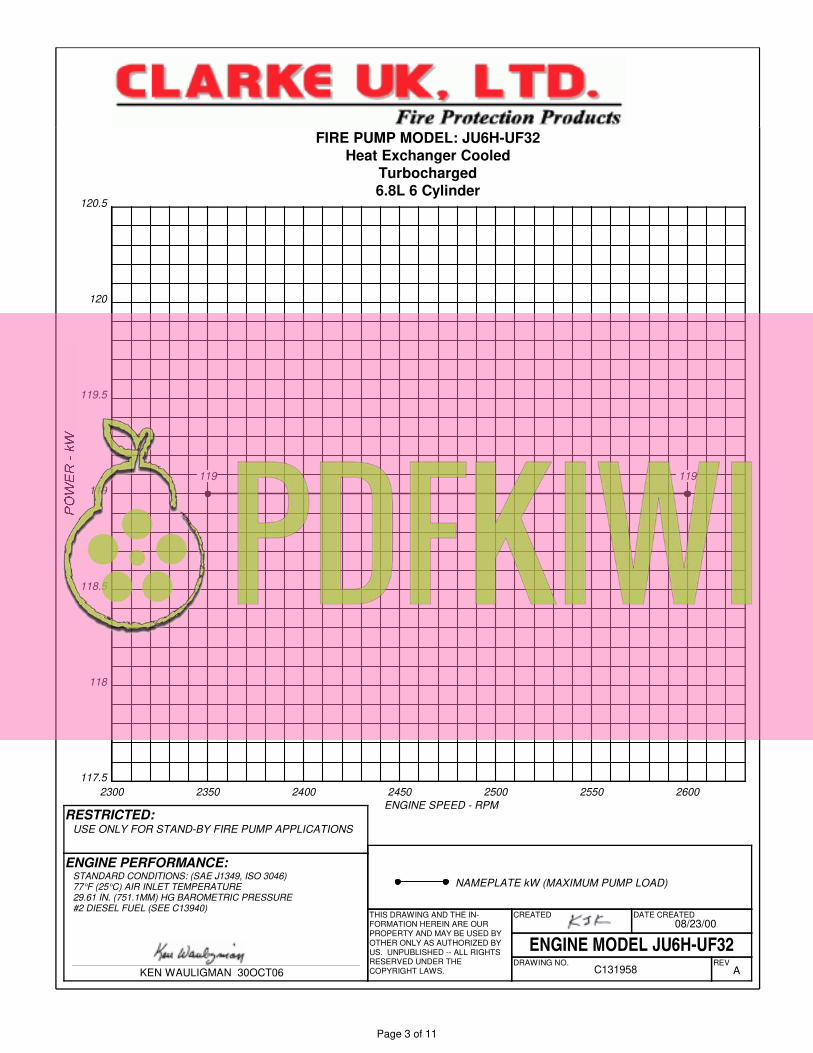
NAMEPLATE kW (MAXIMUM PUMP LOAD)
119 119
2300 2350 2400 2450 2500 2550 2600
117.5
118
118.5
119
119.5
120
120.5
RESTRICTED:
DATE CREATED
DRAWING NO. REVA
ENGINE MODEL JU6H-UF32
08/23/00
C131958
THIS DRAWING AND THE IN-FORMATION HEREIN ARE OUR PROPERTY AND MAY BE USED BY OTHER ONLY AS AUTHORIZED BY US. UNPUBLISHED -- ALL RIGHTS RESERVED UNDER THECOPYRIGHT LAWS.KEN WAULIGMAN 30OCT06
CREATED
USE ONLY FOR STAND-BY FIRE PUMP APPLICATIONS
FIRE PUMP MODEL: JU6H-UF32
Heat Exchanger Cooled
Turbocharged
6.8L 6 Cylinder
ENGINE SPEED - RPM
STANDARD CONDITIONS: (SAE J1349, ISO 3046)77°F (25°C) AIR INLET TEMPERATURE29.61 IN. (751.1MM) HG BAROMETRIC PRESSURE#2 DIESEL FUEL (SEE C13940)
ENGINE PERFORMANCE:
Page 3 of 11
JU6H-UF30
UK Produced
INSTALLATION & OPERATION DATA (I&O Data)
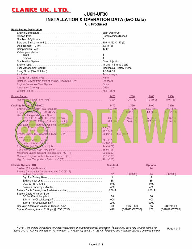
Basic Engine Description
Engine Manufacturer John Deere Co.
Ignition Type Compression (Diesel)
Number of Cylinders 6
Bore and Stroke - mm (in) 106 (4.19) X 127 (5)
Displacement - L (in³) 6.8 (415)
Compression Ratio 17.0:1
Valves per cylinderIntake 1
Exhaust 1
Combustion System Direct Injection
Engine Type In-Line, 4 Stroke Cycle
Fuel Management Control Mechanical, Rotary Pump
Firing Order (CW Rotation) 1-5-3-6-2-4
Aspiration Turbocharged
Charge Air Cooling Type None
Rotation, viewed from front of engine, Clockwise (CW) Standard
Engine Crankcase Vent System Open
Installation Drawing D538
Weight - kg (lb) 752 (1657)
Power Rating 1470 1760 2100 2350
Nameplate Power - kW (HP)[1] 70 (94) 104 (140) 119 (160) 119 (160)
Cooling System - [C051002] 1470 1760 2100 2350
Engine Coolant Heat - kW (Btu/sec) 42.2 (40) 57 (54) 63.3 (60) 70.7 (67)
Engine Radiated Heat - kW (Btu/sec) 10.6 (10) 13.2 (12.5) 14.1 (13.4) 14.1 (13.4)
Heat Exchanger Minimum Flow15°C (60°F) Raw H20 - L/min (gal/min) 26.5 (7) 45.4 (12) 53 (14) 60.6 (16)
37°C (100°F) Raw H20 - L/min (gal/min) 37.9 (10) 56.8 (15) 64.3 (17) 71.9 (19)
Heat Exchanger Maximum Cooling Raw WaterInlet Pressure - bar (psi) 4.1 (60)
Flow - L/min (gal/min) 98.4 (26)
Typical Engine H20 Operating Temp - °C (°F) 82.2 (180) - 90.6 (195)
ThermostatStart to Open - °C (°F) 76.7 (170)
Fully Opened - °C (°F) 87.8 (190)
Engine Coolant Capacity - L (qt) 14 (14.79)
Coolant Pressure Cap - kPa (lb/in²) 68.9 (10)
Maximum Engine Coolant Temperature - °C (°F) 93.3 (200)
Minimum Engine Coolant Temperature - °C (°F) 71.1 (160)
High Coolant Temp Alarm Switch - °C (°F) 96.1 (205)
Electric System - DC Standard Optional
System Voltage (Nominal) 12 24
Battery Capacity for Ambients Above 0°C (32°F)Voltage (Nominal) 12 {C07633} 24 {C07633}
Qty. Per Battery Bank 1 2
SAE size per J537 8D 8D
CCA @ -18°C (0°F) 1400 1400
Reserve Capacity - Minutes 430 430
Battery Cable Circuit, Max Resistance - ohm 0.0012 0.0012
Battery Cable Minimum Size0-3.1m Circuit Length[2] 00 00
3.1m-4.1m Circuit Length[2] 000 000
4.1m-5.1m Circuit Length[2] 0000 0000
Charging Alternator Maximum Output - Amp, 40 {C071363} 55 {C071366}
Starter Cranking Amps, Rolling - @15°C (60°F) 440 {C07825/C07837} 250 {C07819/C07820}
NOTE: This engine is intended for indoor installation or in a weatherproof enclosure. 1Derate 3% per every 1000 ft. [304.8 m] above 300 ft. [91.4 m] and derate 1% for every 10 °F [5.55 °C] above 77° [25°C]. 2Positive and Negative Cables Combined Length.
Page 1 of 2
Page 4 of 11
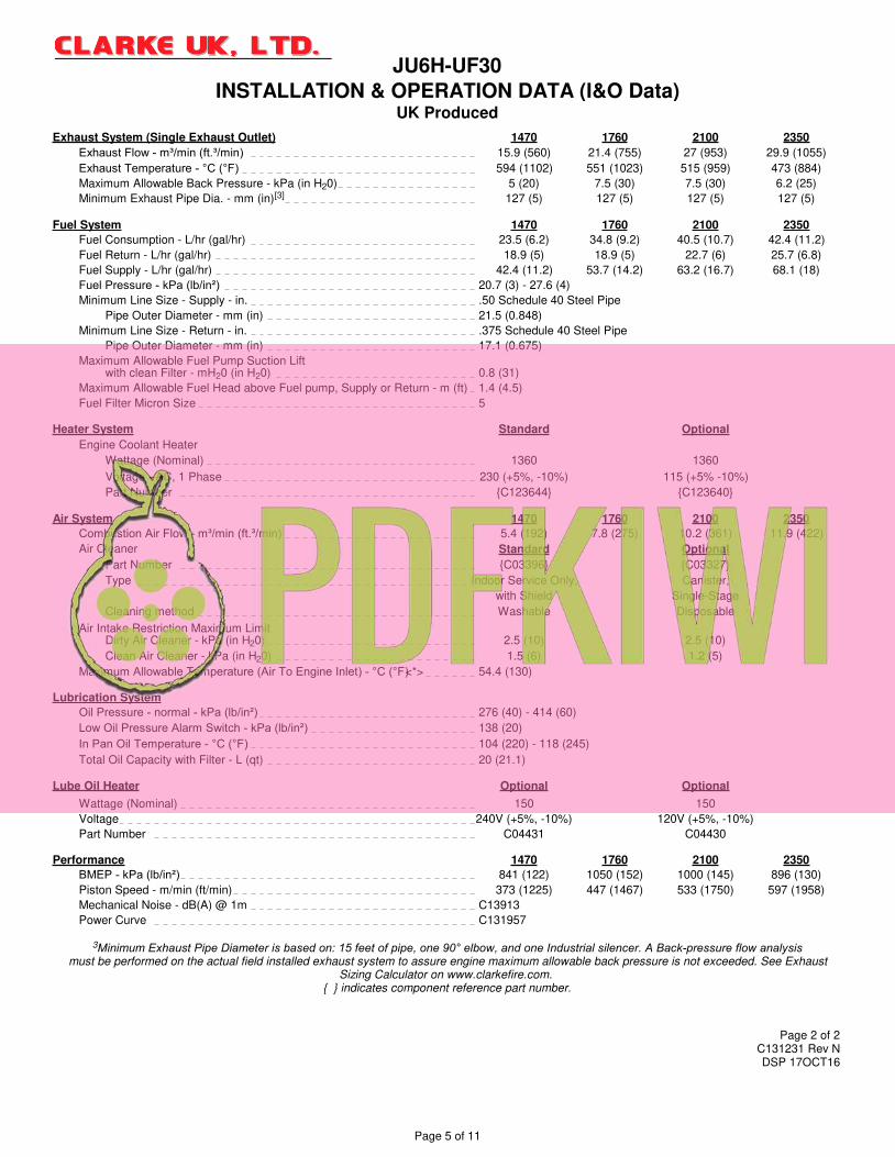
JU6H-UF30
UK Produced
INSTALLATION & OPERATION DATA (I&O Data)
Exhaust System (Single Exhaust Outlet) 1470 1760 2100 2350
Exhaust Flow - m³/min (ft.³/min) 15.9 (560) 21.4 (755) 27 (953) 29.9 (1055)
Exhaust Temperature - °C (°F) 594 (1102) 551 (1023) 515 (959) 473 (884)
Maximum Allowable Back Pressure - kPa (in H20) 5 (20) 7.5 (30) 7.5 (30) 6.2 (25)
Minimum Exhaust Pipe Dia. - mm (in)[3] 127 (5) 127 (5) 127 (5) 127 (5)
Fuel System 1470 1760 2100 2350
Fuel Consumption - L/hr (gal/hr) 23.5 (6.2) 34.8 (9.2) 40.5 (10.7) 42.4 (11.2)
Fuel Return - L/hr (gal/hr) 18.9 (5) 18.9 (5) 22.7 (6) 25.7 (6.8)
Fuel Supply - L/hr (gal/hr) 42.4 (11.2) 53.7 (14.2) 63.2 (16.7) 68.1 (18)
Fuel Pressure - kPa (lb/in²) 20.7 (3) - 27.6 (4)
Minimum Line Size - Supply - in. .50 Schedule 40 Steel Pipe
Pipe Outer Diameter - mm (in) 21.5 (0.848)
Minimum Line Size - Return - in. .375 Schedule 40 Steel Pipe
Pipe Outer Diameter - mm (in) 17.1 (0.675)
Maximum Allowable Fuel Pump Suction Liftwith clean Filter - mH20 (in H20) 0.8 (31)
Maximum Allowable Fuel Head above Fuel pump, Supply or Return - m (ft) 1.4 (4.5)
Fuel Filter Micron Size 5
Heater System Standard Optional
Engine Coolant Heater
Wattage (Nominal) 1360 1360
Voltage - AC, 1 Phase 230 (+5%, -10%) 115 (+5% -10%)
Part Number {C123644} {C123640}
Air System 1470 1760 2100 2350
Combustion Air Flow - m³/min (ft.³/min) 5.4 (192) 7.8 (275) 10.2 (361) 11.9 (422)
Air Cleaner Standard Optional
Part Number {C03396} {C03327}
Type Indoor Service Only, Canister,
with Shield Single-Stage
Cleaning method Washable Disposable
Air Intake Restriction Maximum LimitDirty Air Cleaner - kPa (in H20) 2.5 (10) 2.5 (10)
Clean Air Cleaner - kPa (in H20) 1.5 (6) 1.2 (5)
Maximum Allowable Temperature (Air To Engine Inlet) - °C (°F)<*> 54.4 (130)
Lubrication System
Oil Pressure - normal - kPa (lb/in²) 276 (40) - 414 (60)
Low Oil Pressure Alarm Switch - kPa (lb/in²) 138 (20)
In Pan Oil Temperature - °C (°F) 104 (220) - 118 (245)
Total Oil Capacity with Filter - L (qt) 20 (21.1)
Lube Oil Heater Optional Optional
Wattage (Nominal) 150 150
Voltage 240V (+5%, -10%) 120V (+5%, -10%)
Part Number C04431 C04430
Performance 1470 1760 2100 2350
BMEP - kPa (lb/in²) 841 (122) 1050 (152) 1000 (145) 896 (130)
Piston Speed - m/min (ft/min) 373 (1225) 447 (1467) 533 (1750) 597 (1958)
Mechanical Noise - dB(A) @ 1m C13913
Power Curve C131957
3Minimum Exhaust Pipe Diameter is based on: 15 feet of pipe, one 90° elbow, and one Industrial silencer. A Back-pressure flow analysis must be performed on the actual field installed exhaust system to assure engine maximum allowable back pressure is not exceeded. See Exhaust
Sizing Calculator on www.clarkefire.com. { } indicates component reference part number.
Page 2 of 2C131231 Rev NDSP 17OCT16
Page 5 of 11

Air Cleaner Cylinder Head
Type…………..………….. .. Indoor Usage Only Type…….. …………………Slab 2 Valve
Oiled Fabric Pleats Material…………………….Annealed Gray Iron
Material……..…..…….………Surgical Cotton
Aluminum Mesh Cylinder Liners
Type…….. …………………Centrifugal Cast, Wet Liner
Air Cleaner - Optional Material………………..….…Alloy Iron Plateau, Honed
Type………………………….Canister
Material………………………Pleated Paper Fuel Pump
Housing………………..…… Enclosed Type…………………………Diaphragm
Drive…………………………Cam Lobe
Camshaft
Material………….…………..Cast Iron Heat Exchanger (USA) - JU4H & JU6H Only
Chill Hardened Type…………………………Tube & Shell
Location…………...….……. In Block Materials
Drive……………….………..…Gear, Spur Tube & Headers……………Copper
Type of Cam…………..….... Ground Shell…………………………Copper
Electrode……………………Zinc
Type……….. ..…………….Raw Water Cooled Heat Exchanger (UK) - JU4H & JU6H Only
Materials (in contact with raw water) Type…………………………Tube & Bundle
Tubes……………………………90/10 CU/NI
Headers ……………………36500 Muntz Materials
Covers ……………………83600 Red Brass Tube & Headers……………Copper
Plumbing ……………………316 Stainless Steel/ Brass Shell………..……………. Aluminum
90/10 Silicone
Injection Pump
Type……………………….. Rotary
Drive…………………………Gear
Type…...……………………Air to Air Cooled
Materials Lubrication Cooler
Core…………………………Aluminum Type…………………………Plate
Coolant Pump Lubrication Pump
Type……….………………… Centrifugal Type…………………………Gear
Drive……………………………Poly Vee Belt Drive…………………………Gear
Coolant Thermostat Main Bearings
Type……………………………Non Blocking Type…………………………Precision Half Shells
Qty……………………………1 Material………………………Steel Backed-Aluminum
Lined
Cooling Loop (Galvanized)
Tees, Elbows, Pipe…………Galvanized Steel Piston
Ball Valves……………………Brass ASTM B 124, Type and Material…………Aluminum Alloy with
Solenoid Valve………………Brass Reinforced Top Ring Groove
Pressure Regulator…………Bronze Cooling………………………Oil Jet Spray
Strainer………………………Cast Iron (1/2" - 1" loops) or
Bronze (1.25" - 2" loops) Piston Pin
Type…………………………Full Floating - Offset
Cooling Loop (Sea Water) Piston Rings
Tees, Elbows, Pipe…………316 Stainless Steel Number/Piston…………… 3
Ball Valves……………………316 Stainless Steel Top………………………… Keystone Barrel Faced -
Solenoid Valve………………316 Stainless Steel Plasma Coated
Pressure Regulator/StrainerCast Brass ASTM B176 Second………………………Tapered Cast Iron
C87800 Third…………………………Double Rail Type
w/Expander Spring
Cooling Loop (316SS)
Tees, Elbows, Pipe…………316 Stainless Steel Radiator - JU4R & JU6R Only
Ball Valves……………………316 Stainless Steel Type……………………… Plate Fin
Solenoid Valve………………316 Stainless Steel Materials
Pressure Regulator/Strainer316 Stainless Steel Core……………………… Copper & Brass
Tank & Structure……….. Steel
Connecting Rod
Type……………………………I-Beam Taper Optional
Material………………………Forged Steel Alloy Marine Coating…………… Baked Phenolic
Crank Pin Bearings Valves
Type……………………………Precision Half Shell Type…….. …………………Poppet
Number………………………1 Pair Per Cylinder Arrangement………… ……Overhead Valve
Material………………………Wear-Guard Number/Cylinder……………1 intake
1 exhaust
Crankshaft Operating Mechanism……Mechanical Rocker Arm
Material………………………Forged Steel Type of Lifter…………….. Large Head
Type of Balance…………… Dynamic Valve Seat Insert……………Replaceable
Cylinder Block
Type……………………………One Piece with
Non-Siamese Cylinders
Material………………………Annealed Gray Iron
Charge Air Cooler (JU6R-AA67, 59, 61, PF, Q7, RF,
S9, 83 only)
JU4H, JU4R & JU6H, JU6R ENGINE MODELS
ENGINE MATERIALS AND CONSTRUCTION
Charge Air Cooler (JU6H-60,62,68,74,84, ADK0,
AD58, ADNG, ADN0, ADQ0, ADR0, AAQ8, AARG,
ADP8, ADP0, ADT0, AD88, ADR8, AD98, ADS0,
ADW8, ADX8, AD98 only)
C13615 26AUG17
Page 6 of 11

Page 7 of 11

Page 8 of 11

6 Cylinders
Four Cycle
Lean Burn
Turbocharged
2350 160 11.2 (42) 0.26 4.26 0.39 0.19 884 (473) 1055 (30)
2600 160 11.1 (42) 0.33 4.28 0.47 0.25 872 (467) 1236 (35)
Notes:
1)
2)
3)
4) PM is a measure of total particulate matter, including PM10 .
by John Deere Corporation. A copy of the John Deere Emission Warranty can
be found in the Clarke Operation and Maintenance Manual.
Engines are rated at standard conditions of 29.61in. (7521 mm) Hg barometer
and 77°F (25° C) inlet air temperature. (SAE J1349)
CFM
(m3/min)
6068TF220 Base Engine Model manufactured by John Deere Corporation.
For John Deere Emissions Conformance to EPA 40 CFR Part 60 see Page 2 of 2.
The Emission Warranty for this engine is provided directly to the owner
500 PPM SULFUR #2 DIESEL FUEL
JU6H-UF32
Stationary Fire Pump Engine Driver
EMISSION DATAEPA 40 CFR Part 60
FUEL
GAL/HR
(L/HR)
EXHAUSTRPM BHP
(3)GRAMS / HP- HR
PM (4)NMHC CONOx °F (°C)
C131845 REV.C
01NOV 07 KRW
CLARKEFIRE PROTECTION PRODUCTS
3133 EAST KEMPER ROAD
CINCINNATI, OH 45241PAGE 1 OF 2
Page 9 of 11

Page 2 of 2
John Deere Power Systems3801 W. Ridgeway Ave., PO Box 5100Waterloo, Iowa USA 50704-5100
31 October 2007
Subject: Fire Pump Ratings – Conformance to EPA 40 CFR Part 60 (NSPS requirements)
All John Deere stationary fire pump engines conform to the requirements of 40 CFR Part 60. All suchengines include an emission label, stating the engine conforms to the requirements of 40 CFR Part 60. Anexample of the emission label is show below:
This label applies to all of the following engine models, sold to Clarke Fire Protection, for use in stationaryfire pump applications:
All engines conforming to 40 CFR Part 60 (identified by emission label, as shown above) are covered underthe emissions warranty of 40 CFR Part 89.
Sincerely,
Kyle J. TingleRegional Sales Manager, JDPS
Page 10 of 11