
ACCPUD RFPP - Athens-Clarke County
341
DATE: October 2, 2019 TO: Equipment Vendors SUBJECT: Request for Price and Performance Proposal for RFPP #00973 CLOTH DISK FILTER SELECTION You are invited to submit a Price and Performance Proposal (RFPP) for RFPP #00973 CLOTH DISK FILTER SELECTION for the Public Utilities Department (PUD) of the Unified Government of Athens-Clarke County, Georgia. Inquiries regarding this request for price and performance proposal should be made to Toro Holt, Interim Purchasing Administrator at (706) 613-3068 or: [email protected]. The RFPP documents may be obtained at Georgia Procurement Registry or Athens Clarke County or via written request to e-mail [email protected]. Include your company name, address, point of contact, fax number and phone number with your written request. Attached hereto are the general conditions, technical specifications, and submittal format. The written requirements contained in this RFPP shall not be changed or superseded except by written addendum from the Unified Government of Athens-Clarke County Purchasing Division of the Finance Department. Failure to comply with the written requirements for this RFPP may result in rejection of the submittal by the Unified Government. Submittals are to be sealed, marked with the offeror's name and address and labeled: RFPP #00973 CLOTH DISK FILTER SELECTION and delivered to: The Unified Government of Athens-Clarke County Finance Department, Purchasing Division 375 Satula Avenue Athens, GA. 30601 Not later than 3:00 P.M. ET, THURSDAY, OCTOBER 31, 2019 A qualified interpreter for the hearing impaired is available upon request at least 10 (ten) days in advance of the proposal receipt date. Please call (706) 613-3088 for more information for the hearing impaired. This service is in compliance with the Americans with Disabilities Act (ADA). The Unified Government of Athens-Clarke County reserves the right to reject any and all submittals, to waive any technicalities or irregularities and to award contracts based on the highest and best interest of the Unified Government of Athens-Clarke County. Toro Holt Interim Purchasing Administrator THE UNIFIED GOVERNMENT OF ATHENS-CLARKE COUNTY (ACCGOV)
-
Upload
khangminh22 -
Category
Documents
-
view
0 -
download
0
Transcript of ACCPUD RFPP - Athens-Clarke County

DATE: October 2, 2019TO: Equipment VendorsSUBJECT: Request for Price and Performance Proposal for RFPP #00973 CLOTH DISK FILTER
SELECTION
You are invited to submit a Price and Performance Proposal (RFPP) for RFPP #00973 CLOTH DISK FILTER SELECTION for the Public Utilities Department (PUD) of the Unified Government of Athens-Clarke County, Georgia.
Inquiries regarding this request for price and performance proposal should be made to Toro Holt, Interim Purchasing Administrator at (706) 613-3068 or: [email protected].
The RFPP documents may be obtained at Georgia Procurement Registry or Athens Clarke County or via written request to e-mail [email protected]. Include your company name, address, point of contact, fax number and phone number with your written request.
Attached hereto are the general conditions, technical specifications, and submittal format.
The written requirements contained in this RFPP shall not be changed or superseded except by written addendum from the Unified Government of Athens-Clarke County Purchasing Division of the Finance Department. Failure to comply with the written requirements for this RFPP may result in rejection of the submittal by the Unified Government.
Submittals are to be sealed, marked with the offeror's name and address and labeled: RFPP #00973 CLOTH DISK FILTER SELECTION and delivered to:
The Unified Government of Athens-Clarke CountyFinance Department, Purchasing Division375 Satula AvenueAthens, GA. 30601
Not later than 3:00 P.M. ET, THURSDAY, OCTOBER 31, 2019
A qualified interpreter for the hearing impaired is available upon request at least 10 (ten) days in advance of the proposal receipt date. Please call (706) 613-3088 for more information for the hearing impaired. This service is in compliance with the Americans with Disabilities Act (ADA).
The Unified Government of Athens-Clarke County reserves the right to reject any and all submittals, to waive any technicalities or irregularities and to award contracts based on the highest and best interest of the Unified Government of Athens-Clarke County.
Toro Holt Interim Purchasing Administrator
THE UNIFIED GOVERNMENT OF ATHENS-CLARKE COUNTY (ACCGOV)

TABLE OF CONTENTS
SECTION TITLE
I REQUEST FOR PRICE AND PERFORMANCE PROPOSAL SUBMISSION INSTRUCTIONS
II REQUEST FOR PRICE AND PERFORMANCE PROPOSAL OVERVIEW AND PROCEDURES
III EVALUATION AND SELECTION PROCESS
IV MANDATORY PROPOSAL FORMS
A: ADDENDA ACKNOWLEDGMENTB: GEORGIA SECURITY & IMMIGRATION COMPLIANCE (GSIC) AFFIDAVIT
CONTRACTOR AFFIDAVIT & AGREEMENTC: TECHNICIAL SPECIFICATIONSD: PRICE AND PERFORMANCE PROPOSAL FORM
V OPTIONAL FORMSE: BID LIST APPLICATION – should be submitted prior to the bid submission.
If you have never registered to do business with ACCGOV
VI DOCUMENTS CHECK LIST
VII TECHNICAL SPECIFICATIONS

THE UNIFIED GOVERNMENT OF ATHENS-CLARKE COUNTY RFPP #00973 CLOTH DISK FILTER SELECTION Page - 3
SECTION I - REQUEST FOR PRICE AND PERFORMANCE PROPOSAL SUBMISSION INSTRUCTIONS
ALL DOCUMENTS RECEIVED WILL BECOME A PART OF THE OFFICIAL CONTRACT FILE AND MAY BE SUBJECT TO DISCLOSURE.
A complete signed price proposal must include the documents listed below:
PROPOSAL FORMAT: Offerors are expected to examine the specifications, price schedule, and all instructions. Failure to do so will be at the offeror’s risk. Each offeror shall furnish the information required by the solicitation. The proposal, specifications, and price schedule must be signed by an officer of the company, who is legally authorized to enter into a contractual relationship in the name of the offeror.
Cover Letter: A brief cover letter of introduction and interest.
Table of Contents
Acknowledgement of Addenda: Include completed Acknowledgement of Addenda form, from Section IV-A of this RFPP.
Georgia Security & Immigration Compliance (GSIC) Act Affidavit: Include a notarized copy of the GSIC Affidavit form for the contractor and all sub-contractors, from Section IV-B of this RFPP.
Technical Specifications: Include from Section IV-C
Brochures: in the number of copies specified, shall be enclosed as part of the Mandatory requirement for performance evaluation.
Warranty: The offeror shall provide warranty information which complies with requirements set forth in the technical specifications.
Page Limit: The offeror shall limit the proposal to 100 number of pages exclusive of drawings.
PRICE AND PERFORMANCE PROPOSAL FORM: Include a separately sealed paper copy of Section IV-D Price and Proposal Form, in order that price may be evaluated separately. DO NOT include pricing or fees in any other format. Proposals that fail to keep pricing/fees confined to the separately sealed paper copy may be rejected.
OPTIONAL DOCUMENTS CHECKLIST: Section V-F
Bidder’s List Application: If you do not have a vendor number, please fill out a Bid List Application so one may be issued to your company

THE UNIFIED GOVERNMENT OF ATHENS-CLARKE COUNTY RFPP #00973 CLOTH DISK FILTER SELECTION Page - 4
SUBMITTAL FORMAT: ALL bid copies must be submitted in a sealed envelope or container with the OUTER MOST container stating the address, telephone number, the RFPP number and title (RFPP #00973 CLOTH DISK FILTER SELECTION). Also please include your Unified Government of Athens-Clarke County Vendor Number (ACCGOV Vendor number).
If you do not know your vendor number, please call 706-613-3088 or email: [email protected]. If you do not have a vendor number, please fill out a bid list application found at Bid List Application (https://www.athensclarkecounty.com/DocumentCenter/View/45180) so one may be issued to your company). The ACCGOV vendor number is not required to submit a Bid but we encourage companies to apply.
DO NOT INCLUDE PRICE
Two (2) paper copies of the Complete Signed Proposal WITHOUT pricingand
One (1) USB flash drive of the Complete Signed Proposal WITHOUT pricingand
One (1) USB flash drive with a copy of the Proposal WITHOUT Pricing
and One (1) separately sealed paper copy of Section IV-D Price and Performance Proposal Form
(Must be submitted separately in a sealed envelope)
ALL FILES SUBMITTED ON USB FLASH DRIVE MUST BE IN A SINGLE PDF FILE.

THE UNIFIED GOVERNMENT OF ATHENS-CLARKE COUNTY RFPP #00973 CLOTH DISK FILTER SELECTION Page - 5
SECTION II - REQUEST FOR PRICE AND PERFORMANCE PROPOSAL OVERVIEW AND PROCEDURES
A. PURPOSEThe Unified Government of Athens-Clarke County is soliciting Request for Price and Performance Proposal for RFPP #00973 CLOTH DISK FILTER SELECTION in accordance with the attached specifications from responsible vendors. One Disk Filter Manufacturer will be selected to be included in the Contract Documents for construction of the Project.
B. INFORMATION TO OFFERORS1. RFPP TIMETABLE
The anticipated schedule for the RFPP is as follows:RFPP Available...........................................OCTOBER 2, 2019Deadline for submission of questions .........OCTOBER 24, 2019Submittal deadline ......................................3:00 P.M. ET, THURSDAY, OCTOBER 31, 2019 Proposal Valid Until: ..................................JULY 2020Anticipated Contractor Notice-to-Proceed: MAY 2020
2. PROPOSAL SUBMISSION Proposal submission should contain:
1. Two (2) paper copies of the proposal without pricing Paper copies shall be submitted in 3-ring binders with the contents clearly identified on the front and spine. A table of contents shall be provided along with tabbing to separate each section.
2. One (1) USB Flash drive copy of the proposal without pricing 3. One (1) paper copy of the price proposal (Section IV-D)
Proposal must be received by 3:00 P.M. ET, THURSDAY, OCTOBER 31, 2019. Proposals must be submitted in a sealed envelope or container stating on the outside, the offeror's name, address, telephone number, and the RFPP number and title, RFPP #00973 CLOTH DISK FILTER SELECTION to:
The Unified Government of Athens-Clarke CountyFinance Department, Purchasing Division375 Satula AvenueAthens, Georgia 30601
Hand delivered copies may be delivered to the above address ONLY between the hours of 8:00 a.m. and 5:00 p.m. ET, Monday through Friday, excluding holidays observed by the Unified Government of Athens-Clarke County.Offerors are responsible for informing any commercial delivery service, if used, of all delivery requirements and for ensuring that the required address and envelope information appears on the outer wrapper or envelope used by such service.The Submittal must be signed by a company officer who is legally authorized to enter into a contractual relationship in the name of the offeror.

THE UNIFIED GOVERNMENT OF ATHENS-CLARKE COUNTY RFPP #00973 CLOTH DISK FILTER SELECTION Page - 6
3. CONTACT PERSONOfferors are encouraged to contact only the Purchasing Administrator to clarify any part of this RFPP. The contact person for this RFPP is Julie Ann Donahue, CPPB, Purchasing Administrator or Toro Holt, Senior Buyer at (706) 613-3068 or [email protected]. It is requested that all questions that arise prior to the proposal due date be directed to the contact person in writing or email. Any unauthorized contact shall not be used as a basis for responding to this RFPP and also may result in the rejection of the offeror's submittal.
Any inquiries regarding technical aspects of this RFPP may be directed to Vivi Nguyen, Hazen and Sawyer, via email: [email protected].
4. ADDITIONAL INFORMATION/ADDENDAThe Unified Government of Athens-Clarke County will issue responses to inquiries and any other corrections or amendments it deems necessary in written addenda issued prior to the due date. Offerors should not rely on any representations, statements or explanations other than those made in this RFPP or in any addendum to this RFPP. Where there appears to be a conflict between the RFPP and any addenda issued, the last addendum issued will prevail.
Offerors must acknowledge any issued addenda. Proposals which fail to acknowledge the offeror’s receipt of any addendum will result in the rejection of the offer if the addendum contains information which substantively changes the Owner’s requirements.
Offerors who obtain this Request for Price and Performance Proposal from Georgia Procurement Registry or Athens Clarke County/Purchasing (http://www.athensclarkecounty.com/index.aspx?NID=375 ) or from other than the Purchasing Division are advised to re-visit the above websites to obtain any addenda which may be issued prior to the proposal closing date. The Unified Government of Athens-Clarke County assumes no responsibility for Offerors’ failure to acknowledge any addenda issued.
5. WITHDRAWAL OF PROPOSALAn offeror may withdraw his proposal before expiration of the time during which proposals may be submitted without prejudice to the offeror, by submitting a written request of withdrawal to the Purchasing Administrator.
6. LATE SUBMITTAL, LATE MODIFICATIONS AND LATE WITHDRAWALSSubmittals received after the due date and time will not be considered. Modifications received after the due date will not be considered. The Unified Government of Athens-Clarke County assumes no responsibility for the premature opening of a proposal not properly addressed and identified, and/or delivered to the proper designation.
7. REJECTION OF PROPOSALSThe Unified Government of Athens-Clarke County may reject any and all proposals and reserves the right to waive any irregularities or informalities in any proposal or in the submittal procedure. Submittals received after said time or at any place other than the time and place as stated in the notice will not be considered.
8. MINIMUM PROPOSAL ACCEPTANCE PERIODProposals shall be valid and may not be withdrawn for a period of twelve (12) months from the date specified for receipt of proposals.
THE UNIFIED GOVERNMENT OF ATHENS-CLARKE COUNTY RFPP #00973 CLOTH DISK FILTER SELECTION Page - 7
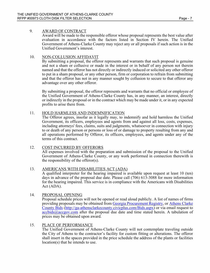
9. AWARD OF CONTRACTAward will be made to the responsible offeror whose proposal represents the best value after evaluation in accordance with the factors listed in Section IV herein. The Unified Government of Athens-Clarke County may reject any or all proposals if such action is in the Unified Government’s interest.
10. NON-COLLUSION AFFIDAVITBy submitting a proposal, the offeror represents and warrants that such proposal is genuine and not a sham or collusive or made in the interest or in behalf of any person not therein named and that the offeror has not directly or indirectly induced or solicited any other offeror to put in a sham proposal, or any other person, firm or corporation to refrain from submitting and that the offeror has not in any manner sought by collusion to secure to that offeror any advantage over any other offeror.
By submitting a proposal, the offeror represents and warrants that no official or employee of the Unified Government of Athens-Clarke County has, in any manner, an interest, directly or indirectly in the proposal or in the contract which may be made under it, or in any expected profits to arise there from.
11. HOLD HARMLESS AND INDEMNIFICATIONThe Offeror agrees, insofar as it legally may, to indemnify and hold harmless the Unified Government, its officers, employees and agents from and against all loss, costs, expenses, including attorneys' fees, claims, suits and judgments, whatsoever in connection with injury to or death of any person or persons or loss of or damage to property resulting from any and all operations performed by Offeror, its officers, employees, and agents under any of the terms of this contract.
12. COST INCURRED BY OFFERORSAll expenses involved with the preparation and submission of the proposal to the Unified Government of Athens-Clarke County, or any work performed in connection therewith is the responsibility of the offeror(s).
13. AMERICANS WITH DISABILITIES ACT (ADA)A qualified interpreter for the hearing impaired is available upon request at least 10 (ten) days in advance of the proposal due date. Please call (706) 613-3088 for more information for the hearing impaired. This service is in compliance with the Americans with Disabilities Act (ADA).
14. PROPOSAL OPENINGProposal schedule prices will not be opened or read aloud publicly. A list of names of firms providing proposals may be obtained from Georgia Procurement Registry, or Athens Clarke County Bids (http://ga-athensclarkecounty.civicplus.com/Bids.aspx) or via email request to [email protected] after the proposal due date and time stated herein. A tabulation of prices may be obtained upon award.
15. PLACE OF PERFORMANCEThe Unified Government of Athens-Clarke County will not contemplate traveling outside the City of Athens to the contractor’s facility for custom fitting or alterations. The offeror shall insert in the spaces provided in the price schedule the address of the plants or facilities location(s) that he intends to use.

THE UNIFIED GOVERNMENT OF ATHENS-CLARKE COUNTY RFPP #00973 CLOTH DISK FILTER SELECTION Page - 8
16. ALTERNATE PROPOSALSAlternate proposals or proposals that deviate substantively from the requirements of this solicitation will not be considered. Offerors shall not insert in their proposal any written statement which will have the effect of making any material change or changes in the Technical Specifications or in any contract between the parties covering subject matter thereof.
17. BRAND NAME OR EQUAL (A) The item in the Price Proposal is identified as "brand name or equal," the Technical Specifications reflect the physical and performance characteristics and level of quality that will satisfy the Department's needs. (B) To be considered for award, offers of "equal" products, including "equal" products of the brand name manufacturer, must-
(1) Meet the salient physical, functional, or performance characteristic specified in the technical specifications;
(2) Clearly identify the item by- (i) Brand name, if any; and (ii) Make or model number;
(3) Include descriptive literature such as illustrations or drawings. (C) The Unified Government of Athens-Clarke County will evaluate "equal" products on the basis of information furnished by the offeror. The Unified Government is not responsible for locating or obtaining any information not identified or submitted with the offer. (D) Unless the offeror clearly indicates in its offer that the product being offered is an "equal" product, the offeror shall provide the brand name product referenced in the price schedule.
18. DELIVERYPrices proposed shall include delivery and shall be F.O.B. Athens, Georgia.
19. DEFINITIONFor the purposes of this Request for Proposals, “applicant” or “contractor” shall mean any contractor presenting their qualifications for the RFPP.
20. SELECTION(A) A selected Manufacturer may be removed from consideration for any of the following reasons:
(1) Failure to enter into an agreement with the Contractor at the prices proposed and under the terms and conditions listed herein, and(2) If its removal is determined by the Owner to be in the best interests of the Owner.
(B) The Owner reserves the right to reject any and all Proposals if it deems such action to be in its best interests. (C) The Owner reserves the right to reject the selected Manufacturer’s equipment at a later date if it is determined that the Manufacturer provided false, misleading or inaccurate information in its Proposal. (D) The Owner reserves the right to reject the selected Manufacturer’s equipment at a later date if it is determined that any of the qualifying criteria that the Manufacturer presented in its Proposal has materially changed to the extent that the long-term use of the equipment would not be in the Owner’s best interests. (E) The Owner reserves the right to waive any requirement that is determined to be in the Owner’s best interests.(F) The decision to select an applicant shall not constitute a determination that the applicant is responsible, and such applicant may be subsequently rejected as non-

THE UNIFIED GOVERNMENT OF ATHENS-CLARKE COUNTY RFPP #00973 CLOTH DISK FILTER SELECTION Page - 9
responsible on the basis of subsequently discovered information. PUD’s action in rejecting an applicant as non-qualified in this regard is final.
21. PRICING(A) The selected Disk Filter Manufacturer agrees that the promise by the Owner to identify the selected Manufacturer in the Contract Documents shall be the consideration for the selected Manufacturer to offer and hold open its Proposal Price for the bidding contractors. (B) The proposal price for the selected Disk Filter Manufacturer will be included in Section 00300, Bid Form, of the construction Contract Documents.(C) Information included in the Proposal that describes the equipment and services to be supplied and associated costs will be included in the Contract Documents for construction as an Appendix to the Specifications. (D) Prices shall be provided for the equipment and services described herein for the Project under the terms and conditions agreed upon with the Contractor in accordance with the Contract Documents. (E) To clarify, the price given in the Proposal shall be the price that the Contractor can use for a purchase order for the goods and services as long as the Notice to Proceed to the Contractor is issued by PUD within 12 calendar months from the date of opening the proposals. It shall be understood that actual delivery of the goods and services will occur substantially after the Notice to Proceed is executed consistent with the progress of the construction contract. The Proposal shall include a letter signed by an officer of the corporation acknowledging these terms as specified herein.
THE UNIFIED GOVERNMENT OF ATHENS-CLARKE COUNTY RFPP #00973 CLOTH DISK FILTER SELECTION Page - 10
SECTION III - EVALUATION AND SELECTION PROCESS
A. PROJECT DESCRIPTION
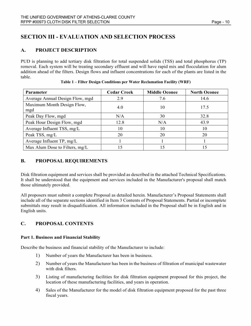
PUD is planning to add tertiary disk filtration for total suspended solids (TSS) and total phosphorus (TP) removal. Each system will be treating secondary effluent and will have rapid mix and flocculation for alum addition ahead of the filters. Design flows and influent concentrations for each of the plants are listed in the table.
Table 1 – Filter Design Conditions per Water Reclamation Facility (WRF)
Parameter Cedar Creek Middle Oconee North OconeeAverage Annual Design Flow, mgd 2.9 7.6 14.6Maximum Month Design Flow, mgd 4.0 10 17.5
Peak Day Flow, mgd N/A 30 32.8Peak Hour Design Flow, mgd 12.8 N/A 43.9Average Influent TSS, mg/L 10 10 10Peak TSS, mg/L 20 20 20Average Influent TP, mg/L 1 1 1Max Alum Dose to Filters, mg/L 15 15 15
B. PROPOSAL REQUIREMENTS
Disk filtration equipment and services shall be provided as described in the attached Technical Specifications. It shall be understood that the equipment and services included in the Manufacturer's proposal shall match those ultimately provided.
All proposers must submit a complete Proposal as detailed herein. Manufacturer’s Proposal Statements shall include all of the separate sections identified in Item 3 Contents of Proposal Statements. Partial or incomplete submittals may result in disqualification. All information included in the Proposal shall be in English and in English units.
C. PROPOSAL CONTENTS
Part 1. Business and Financial Stability
Describe the business and financial stability of the Manufacturer to include:
1) Number of years the Manufacturer has been in business.
2) Number of years the Manufacturer has been in the business of filtration of municipal wastewater with disk filters.
3) Listing of manufacturing facilities for disk filtration equipment proposed for this project, the location of these manufacturing facilities, and years in operation.
4) Sales of the Manufacturer for the model of disk filtration equipment proposed for the past three fiscal years.

THE UNIFIED GOVERNMENT OF ATHENS-CLARKE COUNTY RFPP #00973 CLOTH DISK FILTER SELECTION Page - 11
Part 2. Description of Equipment Proposed
Describe, through use of technical drawings and technical literature, how the Manufacturer’s proposed equipment meets or exceeds the attached Technical Specifications. The Manufacturer shall include a description of all auxiliary or support equipment in its submittal that is to be provided by Manufacturer under the attached Technical Specifications. Each technical feature required by the Technical Specifications shall be provided. Features that are included in the equipment type or model for the first time are not acceptable. Minor exceptions may be waived at the discretion of the Owner during the review of the proposals.
The Manufacturer shall provide dimensions of all equipment in the scope of supply (including disk filter units, backwash systems, enclosures, electrical and control equipment, etc.). In addition to dimensions, the Manufacturer shall provide a general arrangement drawing for the Owner showing proposed layout of the new disk filtration system. Ancillary equipment including backwash systems for cleaning, control panels, and any other control or electrical equipment recommended shall be shown. Drawings shall be provided in hard copy format (11”x17”) and upon request in electronic format (AutoCAD 2012 or compatible). The following items shall be included in the general arrangement drawings at a minimum for each of the three (3) facilities (items which apply to all three facilities equally may be submitted once):
Disk filter unit width, depth, length, and filter spacing requirements Panel and enclosure dimensions and spacing requirements
Layout of influent, effluent, backwash, solids waste, and bypass piping
Operational weight of all system components and the total weight of each filter unit
Hydraulic profile through the filter showing weir lengths, elevations, and nappe at design and peak flows
Max headloss at peak flow
In addition to drawings, Manufacturer shall submit the following:
Description and frequency of typical chemical cleaning procedures and chemicals
Description of the filtration media mounted on the disks and the replacement procedure
Manufacturer’s specification for the submitted system(s)
Manufacturer shall provide calculations verifying the effective filtration surface area. Manufacturer shall provide detailed calculations demonstrating how the proposed equipment does not exceed a hydraulic loading rate of 6.5 gpm/sf or the manufacturer’s peak hydraulic loading permitted per California Title 22 approval, whichever is lower, at 75% of current design peak flows with one unit out of service and peak flows with all units in service.
Manufacturer shall certify that the filter media is capable of operating at the specified solids loading rate of 2.0 lbs/ft2-day. The filter system shall be capable of filtering secondary effluent containing up to 20 mg/L of total suspended solids at the peak hydraulic loading rate listed in the table above, at 75% of current design peak flows with one unit out of service and peak flows with all units in service .
Manufacturer shall state whether equipment will fit in the existing hydraulic profile for all three plants which are shown in Appendix A. If proposed equipment will not fit in the existing hydraulic profile, state additional head required (in feet) required in order for system to function as intended.
THE UNIFIED GOVERNMENT OF ATHENS-CLARKE COUNTY RFPP #00973 CLOTH DISK FILTER SELECTION Page - 12
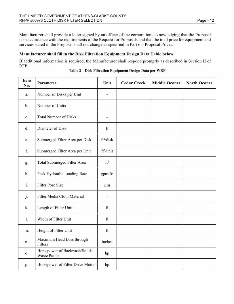
Manufacturer shall provide a letter signed by an officer of the corporation acknowledging that the Proposal is in accordance with the requirements of the Request for Proposals and that the total price for equipment and services stated in the Proposal shall not change as specified in Part 6 – Proposal Prices.
Manufacturer shall fill in the Disk Filtration Equipment Design Data Table below.
If additional information is required, the Manufacturer shall respond promptly as described in Section II of RFP.
Table 2 – Disk Filtration Equipment Design Data per WRF
ItemNo. Parameter Unit Cedar Creek Middle Oconee North Oconee
a. Number of Disks per Unit -
b. Number of Units -
c. Total Number of Disks -
d. Diameter of Disk ft
e. Submerged Filter Area per Disk ft2/disk
f. Submerged Filter Area per Unit ft2/unit
g. Total Submerged Filter Area ft2
h. Peak Hydraulic Loading Rate gpm/ft2
i. Filter Pore Size µm
j. Filter Media Cloth Material -
k. Length of Filter Unit ft
l. Width of Filter Unit ft
m. Height of Filter Unit ft
n. Maximum Head Loss through Filters inches
o. Horsepower of Backwash/Solids Waste Pump hp
p. Horsepower of Filter Drive Motor hp

THE UNIFIED GOVERNMENT OF ATHENS-CLARKE COUNTY RFPP #00973 CLOTH DISK FILTER SELECTION Page - 13
Part 3. Exceptions Taken to Technical Specifications
The Manufacturer shall state all exceptions taken to the Technical Specifications requirements, including any requirements in Reference Specifications that apply where Reference Specifications are referenced in the Technical Specifications. A copy of the Technical Specifications shall be included in the Proposal with each paragraph marked to show compliance with Specification. A check mark shall indicate complete compliance with paragraph, and an asterisk shall indicate an exception.
For each exception, describe the reason for the exception and describe the alternative proposed by the Manufacturer with supporting calculations and/or documentation. For each exception taken, provide evidence that the alternative proposed has been successfully used at other similar installations, in similar applications.
Part 4. Experience with Installed Equipment
Provide responses to the following questions.
1) Regarding the exact equipment type for the Owner’s particular application, how many installations by the Manufacturer are currently in service in the United States? List location, number of filters or filter units at each location, peak design flow, date of commissioning and service type (primary, tertiary, reuse, phosphorus removal etc.). If the service type was phosphorus removal, list the phosphorous design target limit. Clearly identify the installations which are within a 250-mile radius of Athens, Georgia. Proposer may also list installations under contract but not yet in service, clearly identified as such. A minimum experience of at least ten disk filter installations on municipal wastewater treatment plants that have been in service for at least one year will be required.
2) Provide the following information for five (5) similar installations by the Manufacturer of the equipment type or model proposed with at least the same number of filters as proposed and have been in service over two (2) years and are designed for total phosphorous removal at or below 0.5 mg/L (monthly average). If five (5) installations of the same model equipment are not operational or have not been in service for two years, provide references for all operating systems of the model proposed plus five references for similar models that are treating total phosphorus to at or below 0.5 mg/L. Additional installations may be submitted, and the equipment installed at the other referenced installations should be of similar size and in a similar application to that proposed for the Owner’s plant. All installations shall be filtering secondary effluent municipal wastewater.
a) Plant Name/Location/Ownerb) Disk filtration system peak capacity in MGDc) Owner’s current contact person and phone numberd) Number of filters or filter units installed of the type proposede) Model number of disk filtration equipmentf) Date installed or commissionedg) Whether application is for total phosphorus removalh) Total suspended solids and total phosphorus permit limitsi) Upstream treatment processes (i.e., primary, activated sludge, clarifiers; all three PUD
WRFs will have Biological Nutrient Removal with secondary clarifiers upstream of the disk filters)
j) Routine operation schedule (such as 12 months/year, 24 hours/day)k) Approximate hours run on equipment since installation l) Total phosphorus removal performance with metal salt coagulants added upstream of
secondary clarificationm) Type(s) of mechanical and chemical cleaning systems installed

THE UNIFIED GOVERNMENT OF ATHENS-CLARKE COUNTY RFPP #00973 CLOTH DISK FILTER SELECTION Page - 14
n) Corrective maintenance history (warranty repairs, parts replaced under warranty, parts purchased from manufacturer after warranty)
Part 5. Preventive Maintenance Requirements
Provide a tabulation of preventive maintenance requirements that includes for each task: the task description, recommended frequency of performance, estimated staff hours to perform the task, and equipment, materials, and tools required to perform the task. Identify all the components with a service life less than 20 years and recommended replacement intervals. Tabulation should be from Manufacturer’s standard literature.
Part 6. Service and Parts Facilities and Service Staff
Provide responses to the following questions:
1) State time period to provide shop drawing submittal to the Contractor (after receipt of Purchase Order from Contractor) and time period for fabrication and delivery of disk filtration system (after receipt of approved shop drawing submittal).
2) How many service technicians are currently making service calls within the United States, and in the vicinity (within 200 miles) of the Owner, on the Manufacturer’s equipment? Are these service technicians full-time employees of the Manufacturer or contractors? Provide the normal response time for on-site services from the time of order to the arrival of a service technician.
3) List the locations of the Manufacturer’s service facilities in the United States.
4) List any parts of the scope of supply that is regularly supplied from outside of the U.S.
5) List any wear parts that are regularly supplied from outside the U.S with typical lead times per item.
Part 7. Service Agreement
Include Manufacturer’s standard service agreement for five (5) years with guaranteed price.

THE UNIFIED GOVERNMENT OF ATHENS-CLARKE COUNTY RFPP #00973 CLOTH DISK FILTER SELECTION Page - 15
D. METHOD OF SELECTION
A. Selection will be accomplished via an evaluation which takes all evaluation criteria into consideration, including purchase price and life cycle cost evaluation, to obtain the best value for the Owner. The selection committee will consider data and information supplied by the Manufacturer in its Proposal, data and information obtained from plant contact references provided by the Manufacturer in its Proposal, the Owner’s own experience with the Manufacturer’s equipment, and any other pertinent information available to the committee.
B. The selection will be made by a committee assigned by the Owner. Once the selection has been made, such selection is final.
C. The Owner expects to procure quality disk filtration equipment via the Contractor and Manufacturer that will serve the intended process function over the life of the equipment (20 years) without undue preventive or corrective maintenance. The Owner requires the use of equipment that has been successfully used at other similar wastewater treatment plants. To be selected, a Manufacturer must demonstrate through its Proposal that:
1) The Manufacturer and its parent firm is an established, financially stable, ongoing business.
2) The equipment model proposed by the Manufacturer complies with the attached Technical Specifications. Each technical feature required by the Technical Specification must be provided. Minor exceptions may be waived at the discretion of the Owner, at the time of the review of the proposal.
3) The exceptions taken by the Manufacturer do not affect the quality, performance, durability, or longevity of the equipment.
4) It is required that the equipment proposed have a track record at facilities similar to the facilities listed in Table 1 and be of similar size and used in a similar application to that required for this installation.
5) The equipment proposed requires an acceptable level of preventive maintenance.
6) The Manufacturer must have an active service organization currently available in the vicinity of the Owner, readily accessible to the Owner, and the Manufacturer must have an active parts-stocking warehouse and service facility where all parts of any supplied equipment can be obtained and/or repaired in the United States or Canada, readily accessible to the Owner.
D. Additional information, test data, or clarification of information presented by the Manufacturer in the Proposal or obtained from plant references may be requested as part of the evaluation process. Written responses by the Manufacturer will be considered part of its Proposal if received within the requested time period.

THE UNIFIED GOVERNMENT OF ATHENS-CLARKE COUNTY RFPP #00973 CLOTH DISK FILTER SELECTION Page - 16
E. EVALUATION METHODOLOGY
A. General. Each response will be scored via the format illustrated below, with the highest score representing the highest ranked Manufacturer.
B. Evaluation Scoring. Evaluation scoring will use the following categories and will be weighted as shown:
Table 3 – Cloth Disk Filtration Equipment Proposal Evaluation Methodology
Evaluation Category Maximum Points
Equipment Features 70
Experience with Installed Equipment 90
Operations and Maintenance 50
Costs 90
Maximum Total Points 300
C. Notes on Evaluation (Non-Cost Criteria)
1) Installed Equipment points will be determined by the Manufacturer who has the most installations in the US and the most local installations, defined as installations within 200-miles of Athens, GA and number of installations designed specifically for total phosphorus removal below 0.5 mg/L in the US.
D. Notes on Evaluation (Cost Criteria)
1) Equipment cost points will be determined as follows:
𝑴𝒂𝒏𝒖𝒇𝒂𝒄𝒕𝒖𝒓𝒆𝒓'𝒔 𝑬𝒒𝒖𝒊𝒑𝒎𝒆𝒏𝒕 𝑪𝒐𝒔𝒕 𝑷𝒐𝒊𝒏𝒕𝒔
=𝐋𝐨𝐰𝐞𝐬𝐭 𝐄𝐪𝐮𝐢𝐩𝐦𝐞𝐧𝐭 𝐂𝐨𝐬𝐭 𝐨𝐟 𝐌𝐚𝐧𝐮𝐟𝐚𝐜𝐭𝐮𝐫𝐞𝐫 𝐌𝐞𝐞𝐭𝐢𝐧𝐠 𝐀𝐥𝐥 𝐄𝐯𝐚𝐥𝐮𝐚𝐭𝐢𝐨𝐧 𝐂𝐫𝐢𝐭𝐞𝐫𝐢𝐚
𝐀𝐩𝐩𝐥𝐢𝐜𝐚𝐧𝐭’𝐬 𝐄𝐪𝐮𝐢𝐩𝐦𝐞𝐧𝐭 𝐂𝐨𝐬𝐭 𝒙 𝑴𝒂𝒙 𝑷𝒐𝒊𝒏𝒕𝒔
2) “Life Cycle Cost” represents the sum of equipment costs and the 20-year present worth of operations and maintenance costs. Operations and maintenance costs shall include average annual filter media replacement costs; average annual backwash spray nozzle or vacuum shoe replacement costs; average annual power costs for design average flows; and average annual filter media cleaning and maintenance costs.
3) Life cycle cost points will be determined as follows:
𝑴𝒂𝒏𝒖𝒇𝒂𝒄𝒕𝒖𝒓𝒆𝒓'𝒔 𝑳𝒊𝒇𝒆 𝑪𝒚𝒄𝒍𝒆 𝑪𝒐𝒔𝒕 𝑷𝒐𝒊𝒏𝒕𝒔
=𝐋𝐨𝐰𝐞𝐬𝐭 𝐋𝐢𝐟𝐞 𝐂𝐲𝐜𝐥𝐞 𝐂𝐨𝐬𝐭 𝐨𝐟 𝐌𝐚𝐧𝐮𝐟𝐚𝐜𝐭𝐮𝐫𝐞𝐫 𝐌𝐞𝐞𝐭𝐢𝐧𝐠 𝐀𝐥𝐥 𝐄𝐯𝐚𝐥𝐮𝐚𝐭𝐢𝐨𝐧 𝐂𝐫𝐢𝐭𝐞𝐫𝐢𝐚
𝐀𝐩𝐩𝐥𝐢𝐜𝐚𝐧𝐭’𝐬 𝐋𝐢𝐟𝐞 𝐂𝐲𝐜𝐥𝐞 𝐂𝐨𝐬𝐭 𝒙 𝑴𝒂𝒙 𝑷𝒐𝒊𝒏𝒕𝒔

THE UNIFIED GOVERNMENT OF ATHENS-CLARKE COUNTY RFPP #00973 CLOTH DISK FILTER SELECTION Page - 17
4) O&M life cycle cost will be determined as the sum of the following:
a) 20-year Present Worth of Average Annual Cost for Replacement Filter Media (based on Manufacturer’s guaranteed replacement filter media cost, number of filters, and Manufacturer’s non-prorated guarantee for hours of filter media life at design average flow)
b) 20-year Present Worth of Average Annual Cost for Replacement Backwash Spray Nozzles or Vacuum Shoes (based on Manufacturer’s non-prorated guaranteed replacement backwash spray nozzle or vacuum shoe cost, number of spray nozzles or vacuum shoes, and guaranteed spray nozzle or vacuum shoe life)
c) 20-year Present Worth of Average Annual Power Cost (based on Manufacturer’s guarantee for power consumption at design average flow and design backwash rate)
d) 20-year Present Worth of Average Annual Filter Media Cleaning and Maintenance Costs Including Chemical Costs (based on Manufacturer’s guarantee for design cleaning schedules)
5) The life cycle cost of filter media will be determined as follows:
The 20-year Present Worth of Average Annual Filter Media Cost (n=20) at a discount rate (i) of 1.5% =
(𝑃𝑊𝑓𝑎𝑐𝑡𝑜𝑟)𝑥(#𝑜𝑓 𝐹𝑖𝑙𝑡𝑒𝑟 𝑀𝑒𝑑𝑖𝑎 𝑆𝑒𝑐𝑡𝑖𝑜𝑛𝑠/𝑈𝑛𝑖𝑡)𝑥(#𝑜𝑓 𝐹𝑖𝑙𝑡𝑒𝑟 𝑈𝑛𝑖𝑡𝑠)𝑥(𝑀𝑒𝑑𝑖𝑎 𝑅𝑒𝑝𝑙𝑎𝑐𝑒𝑚𝑒𝑛𝑡 𝐶𝑜𝑠𝑡)(𝐺𝑢𝑎𝑟𝑎𝑛𝑡𝑒𝑒𝑑 𝐹𝑖𝑙𝑡𝑒𝑟 𝑀𝑒𝑑𝑖𝑎 𝐿𝑖𝑓𝑒)
Where the 20-year PW Factor =
= 17.17(1 + 𝑖)𝑛 ‒ 1
(𝑖 × (1 + 𝑖)𝑛)
6) The life cycle cost of backwash spray nozzles or vacuum shoes will be determined as follows:
20-year Present Worth of Average Annual Spray Nozzle/Vacuum Shoe Cost =
(𝑃𝑊𝑓𝑎𝑐𝑡𝑜𝑟)𝑥(#𝑜𝑓 𝐵𝑎𝑐𝑘𝑤𝑎𝑠ℎ 𝑆𝑝𝑟𝑎𝑦 𝑁𝑜𝑧𝑧𝑙𝑒𝑠)𝑥(𝐵𝑎𝑐𝑘𝑤𝑎𝑠ℎ 𝑆𝑝𝑟𝑎𝑦 𝑁𝑜𝑧𝑧𝑙𝑒 𝑅𝑒𝑝𝑙𝑎𝑐𝑒𝑚𝑒𝑛𝑡 𝐶𝑜𝑠𝑡)(𝐺𝑢𝑎𝑟𝑎𝑛𝑡𝑒𝑒𝑑 𝐵𝑎𝑐𝑘𝑤𝑎𝑠ℎ 𝑆𝑝𝑟𝑎𝑦 𝑁𝑜𝑧𝑧𝑙𝑒 𝐿𝑖𝑓𝑒)
7) The life cycle cost of power will be determined as the sum of the following two equations:
20-year Present Worth of Average Annual Power Cost =
(𝑃𝑊𝑓𝑎𝑐𝑡𝑜𝑟)𝑥(𝑃𝑜𝑤𝑒𝑟 𝑈𝑠𝑒 𝐷𝑢𝑟𝑖𝑛𝑔 𝑁𝑜𝑟𝑚𝑎𝑙 𝑂𝑝𝑒𝑟𝑎𝑡𝑖𝑜𝑛)𝑥(# 𝑜𝑓 𝐷𝑢𝑡𝑦 𝐹𝑖𝑙𝑡𝑒𝑟 𝑈𝑛𝑖𝑡𝑠)𝑥(8,760ℎ𝑟𝑦𝑟)𝑥(
$0.06𝑘𝑊ℎ )
20-year Present Worth of Annual Backwash Power Cost =
(𝑃𝑊𝑓𝑎𝑐𝑡𝑜𝑟)𝑥(𝑃𝑜𝑤𝑒𝑟 𝑈𝑠𝑒 𝐷𝑢𝑟𝑖𝑛𝑔 𝑂𝑛𝑒 𝐵𝑎𝑐𝑘𝑤𝑎𝑠ℎ 𝐶𝑦𝑐𝑙𝑒)𝑥(# 𝑜𝑓 𝐷𝑢𝑡𝑦 𝐹𝑖𝑙𝑡𝑒𝑟 𝑈𝑛𝑖𝑡𝑠)𝑥(#𝑜𝑓 𝐵𝑎𝑐𝑘𝑤𝑎𝑠ℎ 𝐶𝑦𝑐𝑙𝑒𝑠 𝑝𝑒𝑟 𝑌𝑒𝑎𝑟)𝑥($0.06𝑘𝑊ℎ )

THE UNIFIED GOVERNMENT OF ATHENS-CLARKE COUNTY RFPP #00973 CLOTH DISK FILTER SELECTION Page - 18
8) The life cycle cost of filter media cleaning will be determined as follows:
20-year Present Worth of Average Annual Filter Media Cleaning Cost =
(𝑃𝑊𝑓𝑎𝑐𝑡𝑜𝑟)𝑥(#𝑜𝑓 𝐹𝑖𝑙𝑡𝑒𝑟 𝑀𝑒𝑑𝑖𝑎 𝐶𝑙𝑒𝑎𝑛𝑖𝑛𝑔𝑠 𝑝𝑒𝑟 𝑌𝑒𝑎𝑟)𝑥(𝐴𝑚𝑜𝑢𝑛𝑡 𝑜𝑓 𝐶ℎ𝑒𝑚𝑖𝑐𝑎𝑙 𝑝𝑒𝑟 𝐶𝑙𝑒𝑎𝑛𝑖𝑛𝑔)𝑥(𝐶ℎ𝑒𝑚𝑖𝑐𝑎𝑙 𝐶𝑜𝑠𝑡𝑠)
Table 4 – Chemical Unit Costs
CHEMICAL UNIT COSTSodium Hypochlorite (12.5 weight percent solution) $ 1.62 per pound Cl2
Citric Acid (50 weight percent solution) $ 0.96 per pound C6H8O7
9) For other evaluation criteria, the highest rated manufacturer for the individual criteria will receive the full point value. Other manufacturers will receive points as judged relative to the highest rated manufacturer.

THE UNIFIED GOVERNMENT OF ATHENS-CLARKE COUNTY RFPP #00973 CLOTH DISK FILTER SELECTION Page - 19
MANDATORY SUBMITTAL
SECTION IV – PROPOSAL FORMS
A: ADDENDA ACKNOWLEDGEMENT
The Offeror has examined and carefully studied the Specifications and the following Addenda, receipt of all of which is hereby acknowledged:
Addendum No. dated Acknowledgement
Addendum No. dated Acknowledgement
Addendum No. dated Acknowledgement
Addendum No. dated Acknowledgement
Offerors must acknowledge any issued addenda. Proposals which fail to acknowledge the Offeror’s receipt of any addenda will result in the rejection of the proposal if the addenda contained information which substantively changes the Owner’s requirements.

THE UNIFIED GOVERNMENT OF ATHENS-CLARKE COUNTY RFPP #00973 CLOTH DISK FILTER SELECTION Page - 20
MANDATORY SUBMITTAL
SECTION IV – PROPOSAL FORMS
B: GEORGIA SECURITY & IMMIGRATION COMPLIANCE (GSIC) AFFIDAVIT
The Unified Government of Athens-Clarke County and Contractor agree that compliance with the requirements of O.C.G.A. § 13-10-91, as amended, are conditions of this Agreement for the physical performance of services.
If employing or contracting with any subcontractor(s) in connection with this Agreement, Contractor further agrees:
(1) To secure from the subcontractor(s) an affidavit attesting to the subcontractor’s compliance with by O.C.G.A. § 13-10-91(b), as amended; such affidavit being in a form similar to and containing the same information as the form attached hereto; and
(2) To obtain such subcontractor affidavit(s) when the subcontractor(s) is retained. Contractor shall have such forms available for inspection and submit to the Owner, if so requested by the Owner.
The failure of Contractor to supply the affidavit of compliance at the time of the bid will be cause for the bid being deemed non-responsive. Failure of Contractor to continue to satisfy the obligations of O.C.G.A. § 13-10-91, as amended throughout the entire contract period shall constitute a material breach of the contract. Upon notice of such breach, Contractor shall be entitled to cure the breach within ten days, upon providing satisfactory evidence of compliance with the terms of this Agreement and State law. Should the breach not be cured, Athens-Clarke County shall be entitled to all available remedies, including termination of the contract and damages.
SEE AFFIDAVITS ON FOLLOWING PAGES

THE UNIFIED GOVERNMENT OF ATHENS-CLARKE COUNTY RFPP #00973 CLOTH DISK FILTER SELECTION Page - 21
MANDATORY SUBMITTAL
CONTRACTOR AFFIDAVIT & AGREEMENT UNDER O.C.G.A. § 13-10-91(b)(1)(effective July 1, 2013)
By executing this affidavit, the undersigned contractor verifies its compliance with O.C.G.A. § 13-10-91, as amended, stating affirmatively that the individual, firm or corporation which is engaged in the physical performance of services on behalf of The Unified Government of Athens-Clarke County, Georgia, has registered with, is authorized to use, and uses the federal work authorization program commonly known as E-Verify, or any subsequent replacement program, in accordance with the provisions and deadlines established in O.C.G.A. § 13-10-91, as amended.
Furthermore, the undersigned will continue to use the federal work authorization program throughout the contract period and the undersigned contractor will contract for the physical performance of services in satisfaction of such contract only with subcontractors who present an affidavit to the contractor with the information required by O.C.G.A. § 13-10-91(b). Contractor hereby attests that its federal work authorization user identification number and date of authorization are as follows:
______________________________________________ ___________________________Federal Work Authorization User Identification Number Date of Authorization
Name of Contractor: _______________________________________________________________
Name of Project: _______________________________________________________________
Name of Public Employer: _The Unified Government of Athens – Clarke County_Georgia________
I hereby declare under penalty of perjury that the foregoing is true and correct.
Executed on ____, ___________, 201__ in _______________________, _____________________.
_________________________________Signature of Authorized Officer or Agent
Printed Name and Title of Authorized Officer or Agent
SUBSCRIBED AND SWORN BEFORE ME ON THIS THE ____ DAY OF ____________, 201_
_____________________________Notary PublicMy Commission Expires:

THE UNIFIED GOVERNMENT OF ATHENS-CLARKE COUNTY RFPP #00973 CLOTH DISK FILTER SELECTION Page - 22
MANDATORY SUBMITTAL
SECTION IV – PROPOSAL FORMS
C: TECHNICAL SPECIFICATIONS
The Unified Government of Athens-Clarke County is requesting Price and Performance Proposals for RFPP #00973 CLOTH DISK FILTER SELECTION The equipment proposed shall be capable of meeting the following performance requirements in an effective and efficient manner for the Public Utilities Department.
The Unified Government of Athens-Clarke County reserves the right to determine whether substitutions or deviations will be acceptable when reviewing specifications on all equipment.
The Technical Specifications are provided in Section VII.

THE UNIFIED GOVERNMENT OF ATHENS-CLARKE COUNTY RFPP #00973 CLOTH DISK FILTER SELECTION Page - 23
MANDATORY SUBMITTAL
SECTION IV – PROPOSAL FORMS
D: PRICE AND PERFORMANCE PROPOSAL FORM
Provide a formal “Quotation” complete with a detailed scope of goods and services suitable for giving to a bidding contractor for the construction contract. Scope of supply shall state that it includes all items required in Specification Section 11360 or be explicitly stated in Section III-C Exceptions. The Manufacturer is hereby notified that the “Schedule of Prices” will be made available to all bidding contractors who request them if the Manufacturer is a selected Manufacturer.
1) Price proposed on Specifications as Outlined: YES NO
2) Price and Performance Proposal Expires on: ______ day of _________, _______ (year)
3) Make/Model #:
a. Cedar Creek WRF __________________________________________________
b. Middle Oconee WRF __________________________________________________
c. North Oconee WRF __________________________________________________
4) DISK FILTRATION SYSTEM SCHEDULE OF PRICES
Item No. Item Description Cedar Creek Middle Oconee North Oconee
1a.Disk Filtration System equipment as described in Section 11360 and Reference Specifications
$ $ $
1b. Spare parts per Section 11360 and Reference Specifications $ $ $
1c. Shipping and insurance $ $ $
1d.
Manufacturer field services including installation certification, commissioning, field functional testing, start-up, acceptance testing, and training services as specified
$ $ $
1e.Submittals including certified shop and installation drawings, and paper and electronic O&M manuals as specified
$ $ $
1f. Total Price – Disk Filtration System (sum of items 1a-1e) $ $ $
1g. 5-year Service Agreement $ $ $

THE UNIFIED GOVERNMENT OF ATHENS-CLARKE COUNTY RFPP #00973 CLOTH DISK FILTER SELECTION Page - 24
MANDATORY SUBMITTAL
5) DISK FILTRATION SYSTEM - LIFE CYCLE COST DATA FOR FILTER MEDIA
Item No. Item Description Cedar Creek Middle Oconee North Oconee
2a. Guaranteed cost for one replacement filter media section $ $ $
2b. Number of filter media sections per filter unit
2c. Number of filter units installed
2d. Guaranteed filter media section life, years
6) DISK FILTRATION SYSTEM - LIFE CYCLE COST DATA FOR BACKWASH SPRAY NOZZLES OR VACUUM SHOES
ItemNo. Item Description Cedar Creek Middle Oconee North Oconee
3a. Guaranteed cost for one replacement spray nozzle or vacuum shoe $ $ $
3b. Number of installed spray nozzles or vacuum shoes in system
3c. Guaranteed spray nozzle or vacuum shoe life, years

THE UNIFIED GOVERNMENT OF ATHENS-CLARKE COUNTY RFPP #00973 CLOTH DISK FILTER SELECTION Page - 25
MANDATORY SUBMITTAL
7) DISK FILTRATION SYSTEM – LIFE CYCLE COST DATA FOR POWER USE
ItemNo. Item Description Cedar Creek Middle Oconee North Oconee
4a.
Guaranteed not-to-exceed Power Use per Filter Unit at Average Design Flow during normal filter operations (not including backwash), kW
4b.Guaranteed not-to-exceed Power Use during one Backwash Cycle per unit, kW-hr
4c.
Guaranteed not-to-exceed number of Backwash Cycles per unit per year at Average Design Flow and Average Influent TSS concentration (15 mg/L TSS), cycles
4d. Number of filter units required to treat Average Annual Design Flow
8) DISK FILTRATION SYSTEM - LIFE CYCLE COST DATA FOR FILTER MEDIA CLEANING AND MAINTENANCE COSTS
ItemNo. Item Description Cedar Creek Middle Oconee North Oconee
5a. Required number of filter media cleanings per year at average design flow
List chemical(s) required for filter media cleaning and amount of chemical(s) used per cleaning. List each chemical separately if more than one. Add more rows if necessary.
5b. Chemical A: ________________________, lb/cleaning
5c. Chemical B: ________________________, lb/cleaning
5d. Chemical C: ________________________, lb/cleaning

THE UNIFIED GOVERNMENT OF ATHENS-CLARKE COUNTY RFPP #00973 CLOTH DISK FILTER SELECTION Page - 26
MANDATORY SUBMITTAL
9) Offeror:
Company:
Contact:
Address:
Phone: Fax:
Email:
Authorized Representative/Title(print or type)
Authorized Representative (Signature) Date

THE UNIFIED GOVERNMENT OF ATHENS-CLARKE COUNTY RFPP #00973 CLOTH DISK FILTER SELECTION Page - 27
SECTION V – OPTIONAL FORMS
E. BID LIST APPLICATION
If you have an ACC Vendor Number please include it on the sealed envelope or container.
If you do not know your ACC Vendor Number, please call 706-613-3088 or email: [email protected]
If you DO NOT HAVE an ACC Vendor Number, please fill out the bidder’s list application attached below.
We would like for this form to be turned in a minimum of four (4) days prior to bid

THE UNIFIED GOVERNMENT OF ATHENS-CLARKE COUNTY RFPP #00973 CLOTH DISK FILTER SELECTION Page - 28
SECTION VI - DOCUMENTS CHECK LIST:
MANDATORY PROPOSAL FORMS Offeror must complete, execute and include with the proposal the following mandatory documents:
A. Price & Performance Proposal Form
B. Acknowledgement of Addenda
C. Georgia Security & Immigration Compliance (GSIC) Act Affidavit
D. Technical Specifications
E. Price and Performance Proposal Form (Must be submitted separately in a sealed envelope)
OPTIONAL FORMS
F. Bidder’s List Application

SECTION VII - TECHNICAL SPECIFICATIONS FOR
PROCUREMENT FOR EQUIPMENT FOR THE
TERTIARY FILTER PROJECT
Volume 1 of 1Technical Specifications
PUBLIC UTILITIES DEPARTMENTUNIFIED GOVERNMENT
OFATHENS-CLARKE COUNTY
GEORGIA
September 2019
Project No. 32440-010
5775 Peachtree Dunwoody RoadSuite D-520
Atlanta, Georgia 30342(404) 459-6363
ISSUED FOR RFPP

ACC PUD RFPP #00973
CLOTH DISK FILTER SELECTION
32440-010 TABLE OF CONTENTS
SEPTEMBER 6, 2019 1
TABLE OF CONTENTS
SPECIFICATIONS
DIVISION 1 - GENERAL REQUIREMENTS
01091 Codes and Standards
01340 Submittals, Shop Drawings, Product Data and Samples
01780 Contract Closeout
DIVISION 5 – METALS
05050 Metal Fastening
DIVISION 9 – FINISHES
09900 Painting
DIVISION 11 – EQUIPMENT GENERAL PROVISION
11000 Equipment General Provisions
11100 Pumps – General
11360 Disk Filtration System
DIVISION 15 – MECHANICAL
15000 Basic Mechanical Requirements
15008 PVC/CPVC Pipe
15095 Valves, General
15100 Valve Operators and Electric Valve Actuators
15104 Ball Valves
15109 Plug Valves
15114 Miscellaneous Valves
15115 PVC/CPVC Valves
15170 Low Voltage Electric Motors
DIVISION 16 – ELECTRICAL
16000 Basic Electrical Requirements
16111 Conduit
16123 Low Voltage Wire and Cable
16130 Boxes
16170 Grounding and Bonding
16190 Supporting Devices
16195 Electrical-Identification
16280 Surge Protective Devices
ACC PUD RFPP #00973
CLOTH DISK FILTER SELECTION
TABLE OF CONTENTS 32440-010
2 SEPTEMBER 6, 2019
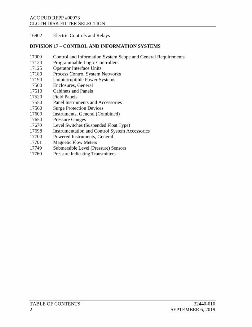
16902 Electric Controls and Relays
DIVISION 17 – CONTROL AND INFORMATION SYSTEMS
17000 Control and Information System Scope and General Requirements
17120 Programmable Logic Controllers
17125 Operator Interface Units
17180 Process Control System Networks
17190 Uninterruptible Power Systems
17500 Enclosures, General
17510 Cabinets and Panels
17520 Field Panels
17550 Panel Instruments and Accessories
17560 Surge Protection Devices
17600 Instruments, General (Combined)
17650 Pressure Gauges
17670 Level Switches (Suspended Float Type)
17698 Instrumentation and Control System Accessories
17700 Powered Instruments, General
17701 Magnetic Flow Meters
17749 Submersible Level (Pressure) Sensors
17760 Pressure Indicating Transmitters

ACC PUD RFPP #00973CLOTH DISK FILTER SELECTION
32440-010 CODES AND STANDARDSAUGUST 28, 2019 01091 - 1
SECTION 01091CODES AND STANDARDS
1 PART 1 GENERAL
1.01 DESCRIPTION
A. Whenever reference is made to conforming to the standards of any technical society, organization, body, code, or standard, it shall be construed to mean the latest standard, code, specification, or tentative specification adopted and published at the time of advertisement for Bids. This shall include the furnishing of materials, testing of materials, fabrication, and installation practices. In those cases where the Contractor's quality standards establish more stringent quality requirements, the more stringent requirement shall prevail. Such standards are made a part hereof to the extent which is indicated or intended.
B. The inclusion of an organization under one category does not preclude that organization’s standards from applying to another category.
C. In addition, all work shall comply with the applicable requirements of local codes, utilities and other authorities having jurisdiction.
D. All material and equipment, for which an Underwriters Laboratories (UL) Standard, an American Gas Association (AGA) or National Sanitation Foundation (NSF) approval, or an ASME requirement is established, shall be so approved and labeled or stamped. The label or stamp shall be conspicuous and not covered, painted, or otherwise obscured from visual inspection.
E. The standards which apply to this Project are not necessarily restricted to those organizations which are listed in Article 1.02 of this section.
1.02 STANDARD ORGANIZATIONS
A. Piping and Valves:
ACPA American Concrete Pipe AssociationANSI American National Standards InstituteAPI American Petroleum InstituteASME American Society of Mechanical EngineersAWWA American Water Works AssociationCISPI Cast Iron Soil Pipe InstituteDIPRA Ductile Iron Pipe Research AssociationFCI Fluid Controls InstituteMSS Manufacturers Standardization SocietyNCPI National Clay Pipe Institute

ACC PUD RFPP #00973CLOTH DISK FILTER SELECTION
CODES AND STANDARDS 32440-01001091 - 2 AUGUST 28, 2019
NSF National Sanitation FoundationPPI Plastic Pipe Institute Uni-Bell PVC Pipe Association
B. Materials:
AASHTO American Association of State Highway and Transportation OfficialsANSI American National Standards InstituteASTM American Society for Testing and Materials
C. Painting and Surface Preparation:
NACE National Association of Corrosion EngineersSSPC Steel Structures Painting Council
D. Steel and Concrete:
ACI American Concrete InstituteAISC American Institute of Steel Construction, Inc.AISI American Iron and Steel InstituteCRSI Concrete Reinforcing Steel InstituteNRMA National Ready-Mix AssociationPCA Portland Cement AssociationPCI Prestressed Concrete Institute
E. Welding:
ASME American Society of Mechanical EngineersAWS American Welding Society
F. Government and Technical Organizations:
AIA American Institute of ArchitectsAPHA American Public Health AssociationAPWA American Public Works AssociationASA American Standards AssociationASAE American Society of Agricultural EngineersASCE American Society of Civil EngineersASQC American Society of Quality ControlASSE American Society of Sanitary EngineersCFR Code of Federal RegulationsCSI Construction Specifications InstituteEDA Economic Development AdministrationEPA Environmental Protection AgencyFCC Federal Communications CommissionFmHA Farmers Home AdministrationFS Federal SpecificationsIAI International Association of Identification

ACC PUD RFPP #00973CLOTH DISK FILTER SELECTION
32440-010 CODES AND STANDARDSAUGUST 28, 2019 01091 - 3
ISEA Industrial Safety Equipment AssociationISO International Organization for StandardizationITE Institute of Traffic EngineersNBFU National Board of Fire UnderwritersNFPA National Fluid Power AssociationNBS National Bureau of StandardsNISO National Information Standards OrganizationOSHA Occupational Safety and Health AdministrationSI Salt InstituteSPI The Society of the Plastics Industry, Inc.USDC United States Department of CommerceWEF Water Environment Federation
G. General Building Construction:
AHA American Hardboard AssociationAHAM Association of Home Appliance ManufacturersAITC American Institute of Timber ConstructionAPA American Parquet Association, Inc.APA American Plywood AssociationBHMA Builders Hardware Manufacturers AssociationBIFMA Business and Institutional Furniture Manufacturers AssociationDHI Door and Hardware InstituteFM Factory Mutual Fire Insurance CompanyHPMA Hardwood Plywood Manufacturers AssociationHTI Hand Tools InstituteIME Institute of Makers of ExplosivesISANTA International Staple, Nail and Tool AssociationISDSI Insulated Steel Door Systems InstituteIWS Insect Screening Weavers AssociationMBMA Metal Building Manufacturers AssociationNAAMM National Association of Architectural Metal ManufacturersNAGDM National Association of Garage Door ManufacturersNCCLS National Committee for Clinical Laboratory StandardsNFPA National Fire Protection AssociationNFSA National Fertilizer Solutions AssociationNKCA National Kitchen Cabinet AssociationNWMA National Woodwork Manufacturers AssociationNWWDA National Wood Window and Door AssociationRMA Rubber Manufacturers AssociationSBC SBCC Standard Building CodeSDI Steel Door InstituteSIA Scaffold Industry AssociationSMA Screen Manufacturers AssociationSPRI Single-Ply Roofing InstituteTCA Tile Council of America

ACC PUD RFPP #00973CLOTH DISK FILTER SELECTION
CODES AND STANDARDS 32440-01001091 - 4 AUGUST 28, 2019
UBC Uniform Building Code
H. Roadways:
AREA American Railway Engineering AssociationDOT Georgia Department of TransportationSSRBC Standard Specifications, Construction of Transportation Systems,
Georgia Department of TransportationDOT&PW Athens-Clarke County Department of Transportation and Public Works
I. Plumbing:
AGA American Gas AssociationNSF National Sanitation FoundationPDI Plumbing Drainage InstituteSPC SBCC Standard Plumbing Code
1.03 SYMBOLS
A. Symbols and material legends shall be as scheduled on the Contract Drawings.
2 PART 2 PRODUCTS (NOT USED)
PART 3 EXECUTION (NOT USED)
END OF SECTION

ACC PUD RFPP #00973CLOTH DISK FILTER SELECTION
32440-010 SUBMITTALS, SHOP DRAWINGS,SEPTEMBER 6, 2019 PRODUCT DATA AND SAMPLES
01340 - 1
SECTION 01340SUBMITTALS, SHOP DRAWINGS, PRODUCT DATA AND SAMPLES
1 PART 1 GENERAL
1.01 SCOPE
A. The Work under this section includes submittal to the Engineer of Shop Drawings, product data, and samples required by the various sections of these Specifications.
B. Submittal Contents: The submittal contents required are specified in each section.
C. Definitions: Submittals are categorized as follows:
1. Submittals:a. Action Submittal: Written and graphic information submitted by
Contractor that requires Engineer’s approval.b. Informational Submittal: Information submitted by Contractor that
requires Engineer’s review and determination that submitted information is in accordance with the Conditions of the Contract.
2. Shop Drawings:a. Shop Drawings shall include technical data, drawings, diagrams,
procedure and methodology, performance curves, schedules, templates, patterns, test reports, calculations, instructions, measurements, and similar information as applicable to the specific item for which the Shop Drawing is prepared.
b. Provide newly prepared information, on reproducible sheets, with graphic information at accurate scale (except as otherwise indicated) or appropriate number of prints hereof, with name of preparer (firm name) indicated. The Contract Drawings shall not be traced or reproduced by any method for use as or in lieu of detail Shop Drawings. Show dimensions and note which are based on field measurement. Identify materials and products in the work shown. Indicate compliance with standards and special coordination requirements. Do not allow Shop Drawing copies without appropriate final "Action" markings by the Engineer to be used in connection with the Work.
c. Drawings shall be presented in a clear and thorough manner. Details shall be identified by reference to sheet and detail, Specification section, schedule, or room numbers shown on the Contract Drawings.
d. Minimum assembly drawings sheet size shall be 24 by 36 inches.

ACC PUD RFPP #00973CLOTH DISK FILTER SELECTION
SUBMITTALS, SHOP DRAWINGS, 32440-010PRODUCT DATA AND SAMPLES SEPTEMBER 6, 201901340 - 2
e. Minimum detail sheet size shall be 8-1/2 by 11 inches.f. Minimum Scale:
1) Assembly Drawings Sheet, Scale: 1 inch = 30 feet.2) Detail Sheet, Scale: 1/4 inch = 1 foot.
3. Product Data:a. Product data includes standard printed information on materials,
products and systems, not specially prepared for this Project, other than the designation of selections from among available choices printed therein.
b. Collect required data into one submittal for each unit of work or system, and mark each copy to show which choices and options are applicable to the Project. Include manufacturer's standard printed recommendations for application and use, compliance with standards, application of labels and seals, notation of field measurements which have been checked, and special coordination requirements.
4. Samples:a. Samples include both fabricated and un-fabricated physical
examples of materials, products, and units of work, both as complete units and as smaller portions of units of work, either for limited visual inspection or, where indicated, for more detailed testing and analysis.
b. Provide units identical with final condition of proposed materials or products for the work. Include "range" samples, not less than three units, where unavoidable variations must be expected, and describe or identify variations between units of each set. Provide full set of optional samples where the Engineer's selection is required. Prepare samples to match the Engineer's sample where indicated. Include information with each sample to show generic description, source or product name and manufacturer, limitations and compliance with standards. Samples are submitted for review and confirmation of color, pattern, texture, and "kind" by the Engineer. Engineer will not "test" samples except as otherwise indicated, for other requirements, which are the exclusive responsibility of the Contractor.
5. Miscellaneous submittals related directly to the Work (non-administrative) include warranties, maintenance agreements, workmanship bonds, project photographs, survey data and reports, physical work records, statements of applicability, quality testing and certifying reports, copies of industry standards, Record Drawings, field measurement data, operating and maintenance materials, overrun stock, security/protection/safety keys and similar information, devices and materials applicable to the Work but not processed as Shop Drawings, product data, or samples.

ACC PUD RFPP #00973CLOTH DISK FILTER SELECTION
32440-010 SUBMITTALS, SHOP DRAWINGS,SEPTEMBER 6, 2019 PRODUCT DATA AND SAMPLES
01340 - 3
1.02 SPECIFIC CATEGORY REQUIREMENTS
A. General: Except as otherwise indicated in the individual work sections, comply with general requirements specified herein for each indicated category of submittal.
1. Submittals shall contain:a. The date of submittal and the dates of any previous submittalsb. The Project titlec. Numerical submittal numbers, starting with the Section that the
submittal references (such as 02665 for Water Mains and Accessories submittals), followed by a submittal number (02665.01, .02, and so on) and version (02665.XX.01, .02, and so on)
d. The Names of:1) Contractor.2) Supplier.3) Manufacturer.
e. Identification of the product, with the Specification section number, permanent equipment tag numbers, and applicable Drawing No.
f. Field dimensions, clearly identified as such.g. Relation to adjacent or critical features of the Work or materials.h. Applicable standards, such as ASTM International (ASTM) or
Federal Specification numbers.i. Notification to the Engineer in writing, at time of submissions, of
any deviations on the submittals from requirements of the Contract Documents.
j. Identification of revisions on resubmittals.k. An 8-inch by 3-inch blank space for Contractor and Engineer
stamps.l. Contractor's stamp, initialed or signed, certifying to review of
submittal, verification of products, field measurements and field construction criteria, and coordination of the information within the submittal with requirements of the Work and of Contract Documents.
m. Submittal sheets or Drawings showing more than the particular item under consideration, shall have all but the pertinent description of the item for which review is requested crossed out.
1.03 PROCEDURES
A. Direct submittals to Engineer at the following, unless specified otherwise.
Hazen and Sawyer

ACC PUD RFPP #00973CLOTH DISK FILTER SELECTION
SUBMITTALS, SHOP DRAWINGS, 32440-010PRODUCT DATA AND SAMPLES SEPTEMBER 6, 201901340 - 4
Attn: Vivi NguyenE-mail: [email protected]
B. Electronic Submittals: Submittals shall, unless specifically accepted, be made in electronic format.
1. Each submittal shall be an electronic file in Adobe Acrobat Portable Document Format (PDF). Use the latest version available at time of execution of the Agreement.
2. Electronic files that contain more than 10 pages in PDF format shall contain internal bookmarking from an index page to major sections of the Document.
3. PDF files shall be set to open “Bookmarks and Page” view.4. Add general information to each PDF file, including title, subject,
author, and keywords.5. PDF files shall be set up to print legibly at 8.5-inch by 11-inch, 11-inch
by 17-inch, or 22-inch by 34-inch. No other paper sizes will be accepted.
6. Submit new electronic files for each resubmittal.7. Include a copy of the Transmittal of Contractor’s Submittal form,
located at end of section, with each electronic file.8. Engineer will reject submittal that is not electronically submitted, unless
specifically accepted.9. Provide Engineer with authorization to reproduce and distribute each
file as many times as necessary for Project documentation.10. Detailed procedures for handling electronic submittals will be discussed
at the preconstruction conference.
C. Transmittal of Submittal:
1. Contractor shall:a. Review each submittal and check for compliance with Contract
Documents.b. Stamp each submittal with uniform approval stamp before
submitting to Engineer.1) Stamp to include Project name, submittal number,
Specification number, Contractor’s reviewer name, date of Contractor’s approval, and statement certifying submittal has been reviewed, checked, and approved for compliance with Contract Documents.
2) Engineer will not review submittals that do not bear Contractor’s approval stamp and will return them without action.
2. Complete, sign, and transmit with each submittal package, Transmittal of Contractor’s Submittal form. Use either the form attached at end of

ACC PUD RFPP #00973CLOTH DISK FILTER SELECTION
32440-010 SUBMITTALS, SHOP DRAWINGS,SEPTEMBER 6, 2019 PRODUCT DATA AND SAMPLES
01340 - 5
this section or in a format approved by Engineer.3. Identify each submittal with the following:
a. Numbering and Tracking System:1) Sequentially number each submittal.2) Resubmission of submittal shall have original number with
sequential alphabetic suffix.b. Specification section and paragraph to which submittal applies.c. Project title and Engineer’s project number.d. Date of transmittal.e. Names of Contractor, Subcontractor or Supplier, and
manufacturer as appropriate.4. Identify and describe each deviation or variation from Contract
Documents.
D. Format:
1. Do not base Shop Drawings on reproductions of Contract Documents.2. Package submittal information by individual Specification section. Do
not combine different specification sections together in submittal package, unless otherwise directed in Specification.
3. Present in a clear and thorough manner and in sufficient detail to show kind, size, arrangement, and function of components, materials, and devices, and compliance with Contract Documents.
4. Index with labeled tab dividers in orderly manner.
E. Timeliness: Schedule and submit in accordance with Schedule of Submittals, and requirements of individual Specification sections.
F. Processing Time:
1. Time for review shall commence on Engineer’s receipt of submittal.2. Engineer will act upon Contractor’s submittal and transmit response to
Contractor not later than 30 days after receipt, unless otherwise specified.
3. Resubmittals will be subject to same review time.4. No adjustment of Contract Times or Price will be allowed as a result of
delays in progress of work caused by rejection and subsequent resubmittals.
G. Resubmittals: Clearly identify each correction or change made.
H. Incomplete Submittals:
1. Engineer will return entire submittal for Contractor’s revision if preliminary review deems it incomplete.
2. When any of the following are missing, submittal will be deemed

ACC PUD RFPP #00973CLOTH DISK FILTER SELECTION
SUBMITTALS, SHOP DRAWINGS, 32440-010PRODUCT DATA AND SAMPLES SEPTEMBER 6, 201901340 - 6
incomplete:a. Contractor’s review stamp, completed and signedb. Transmittal of Contractor’s Submittal, completed and signed.
I. Submittals not required by Contract Documents:
1. Will not be reviewed and will be returned stamped “Not Subject to Review.”
2. Engineer will keep one copy and return submittal to Contractor.
1.04 ACTION SUBMITTALS
A. Prepare and submit Action Submittals required by individual Specification sections.
B. Shop Drawings:
1. Identify and Indicate:a. Applicable Contract Drawing and Detail number, products, units
and assemblies, and system or equipment identification or tag numbers.
b. Equipment and Component Title: Identical to title shown on Drawings.
c. Critical field dimensions and relationships to other critical features of work; Note dimensions established by field measurement
d. Project-specific information drawn accurately to scale2. Manufacturer’s standard schematic drawings and diagrams as follows:
a. Modify to delete information that is not applicable to the Work.b. Supplement standard information to provide information
specifically applicable to the Work.3. Product Data: Provide as specified in individual specifications.4. Foreign Manufacturers: When proposed, include names and addresses
of at least two companies that maintain technical service representatives close to Project.
C. Samples:
1. Copies: Two, unless otherwise specified in individual Specifications.2. Preparation: Mount, display, or package Samples in manner specified to
facilitate review of quality. Attach label on unexposed side that includes the following:a. Manufacturer name.b. Model number.c. Material.d. Sample source.

ACC PUD RFPP #00973CLOTH DISK FILTER SELECTION
32440-010 SUBMITTALS, SHOP DRAWINGS,SEPTEMBER 6, 2019 PRODUCT DATA AND SAMPLES
01340 - 7
3. Manufacturer’s Color Chart: Units or sections of units showing full range of colors, textures, and patterns available.
4. Full-size Samples:a. Size as indicated in individual Specification section.b. Prepared from same materials to be used for the Work.c. Cured and finished in manner specified.d. Physically identical with product proposed for use.
D. Action Submittal Dispositions: Engineer will review, comment, stamp, and distribute as noted:
1. Approved:a. Contractor may incorporate product(s) or implement Work
covered by submittal.b. Distribution: Electronic.
2. Approved as Noted:a. Contractor may incorporate product(s) or implement Work
covered by submittal, in accordance with Engineer’s notations.b. Distribution: Electronic.
3. Partial Approval, Resubmit as Noted:a. Make corrections or obtain missing portions, and resubmit.b. Except for portions indicated, Contractor may begin to incorporate
product(s) or implement Work covered by submittal, in accordance with Engineer’s notations.
c. Distribution: Electronic.4. Revise and Resubmit:
a. Contractor may not incorporate product(s) or implement Work covered by submittal.
b. Distribution: Electronic.
1.05 INFORMATIONAL SUBMITTALS
A. General:
1. Refer to individual Specification sections for specific submittal requirements.
2. Engineer will review each submittal. If submittal meets conditions of the Contract, Engineer will forward copy to appropriate parties. If Engineer determines submittal does not meet conditions of the Contract and is therefore considered unacceptable, Engineer will retain one copy and return remaining copy with review comments to Contractor, and require that submittal be corrected and resubmitted.
B. Certificates:

ACC PUD RFPP #00973CLOTH DISK FILTER SELECTION
SUBMITTALS, SHOP DRAWINGS, 32440-010PRODUCT DATA AND SAMPLES SEPTEMBER 6, 201901340 - 8
1. General:a. Provide notarized statement that includes signature of entity
responsible for preparing certification.b. Certificate must be signed by officer or other individual
authorized to sign documents on behalf of that entity.2. Welding: In accordance with individual Specification sections3. Installer: Prepare written statements on manufacturer’s letterhead
certifying installer complies with requirements as specified in individual Specification section.
4. Material Test: Certificate must be prepared by qualified testing agency, on testing agency’s standard form, indicating and interpreting test results of material for compliance with requirements.
5. Certificates of Successful Testing or Inspection: Submit when testing or inspection is required by Laws and Regulations or governing agency or specified in individual Specification sections.
6. Manufacturer’s Certificate of Compliance7. Manufacturer’s Certificate of Proper Installation
C. Closeout Submittals: In accordance with Section 01780, Contract Closeout.
D. Contractor-design Data (related to temporary construction):
1. Written and graphic information.2. List of assumptions.3. List of performance and design criteria.4. Summary of loads or load diagram, if applicable.5. Calculations.6. List of applicable codes and regulations.7. Name and version of software.8. Information requested in individual Specification section.
E. Manufacturer’s Instructions: Written or published information that documents manufacturer’s recommendations, guidelines, and procedures in accordance with individual Specification section.
F. Special Guarantee: Supplier’s written guarantee as required in individual specification sections.
G. Statement of Qualification: Evidence of qualification, certification, or registration as required in Contract Documents to verify qualifications of professional land surveyor, engineer, materials testing laboratory, specialty Subcontractor, trade, consultant, installer, and other professionals.
H. Submittals Required by Laws, Regulations, and Governing Agencies:
1. Promptly submit notifications, reports, certifications, payrolls, and

ACC PUD RFPP #00973CLOTH DISK FILTER SELECTION
32440-010 SUBMITTALS, SHOP DRAWINGS,SEPTEMBER 6, 2019 PRODUCT DATA AND SAMPLES
01340 - 9
otherwise as may be required, directly to the applicable federal, state, or local governing agency or their representative.
2. Transmit to Engineer for Owner’s records one copy of correspondence and transmittals (to include enclosures and attachments) between Contractor and governing agency.
I. Test, Evaluation, and Inspection Reports:
1. General: Shall contain signature of person responsible for test or report.2. Factory:
a. Identification of product and specification section, type of inspection or test with referenced standard or code.
b. Date of test, Project title and number, and name and signature of authorized person.
c. Test resultsd. If test or inspection deems material or equipment not in
compliance with Contract Documents, identify corrective action necessary to bring into compliance.
e. Provide interpretation of test results, when requested by Engineer.f. Other items as identified in individual Specification sections.
3. Field:a. As a minimum, include the following:
1) Project title and number.2) Date and time.3) Record of temperature and weather conditions.4) Identification of product and specification section.5) Type and location of test, Sample, or inspection, including
referenced standard or code.6) Date issued, testing laboratory name, address, and telephone
number, and name and signature of laboratory inspector.7) If test or inspection deems material or equipment not in
compliance with Contract Documents, identify corrective action necessary to bring into compliance.
8) Provide interpretation of test results, when requested by Engineer.
9) Other items as identified in individual specification sections.
J. Testing and Startup Data
K. Training Data
1.06 ROUTING OF SUBMITTALS
A. Submittals and routine correspondence shall be routed as follows:

ACC PUD RFPP #00973CLOTH DISK FILTER SELECTION
SUBMITTALS, SHOP DRAWINGS, 32440-010PRODUCT DATA AND SAMPLES SEPTEMBER 6, 201901340 - 10
1. Supplier to Contractor (through representative if applicable).2. Contractor to Engineer.3. Engineer to Contractor and Owner.4. Contractor to Supplier.
2 PART 2 PRODUCTS
2.01 MANUFACTURER'S LITERATURE
A. Where content of submitted literature from manufacturers includes data not pertinent to this submittal, clearly indicate which portion of the contents is being submitted for the Engineer's review.
B. Submit the number of copies which are required to be returned (not to exceed three) plus three copies which will be retained by the Engineer.
2.02 SAMPLES
A. Samples shall illustrate materials, equipment, or workmanship and established standards by which completed work is judged.
B. Unless otherwise specifically directed by the Engineer, all samples shall be of the precise article proposed to be furnished.
C. Submit all samples in the quantity which is required to be returned plus one sample which will be retained by the Engineer.
3 PART 3 EXECUTION
3.01 CONTRACTOR'S COORDINATION OF SUBMITTALS
A. Prior to submittal for the Engineer's review, the Contractor shall use all means necessary to fully coordinate all material, including the following procedures:
1. Determine and verify all field dimensions and conditions, catalog numbers, and similar data.
2. Coordinate as required with all trades and all public agencies involved.3. Submit a written statement of review and compliance with the
requirements of all applicable Technical Specifications as well as the requirements of this section.
4. Clearly indicate in a letter or memorandum on the manufacturer's or fabricator's letterhead, all deviations from the Contract Documents.
B. Each and every copy of the Shop Drawings and data shall bear the Contractor's stamp showing that they have been so checked. Shop Drawings submittal to the Engineer without the Contractor's stamp will be returned to

ACC PUD RFPP #00973CLOTH DISK FILTER SELECTION
32440-010 SUBMITTALS, SHOP DRAWINGS,SEPTEMBER 6, 2019 PRODUCT DATA AND SAMPLES
01340 - 11
the Contractor for conformance with this requirement.
C. The Owner may backcharge the Contractor for costs associated with having to review a particular Shop Drawing, product data, or sample more than two times to receive a "No Exceptions Taken" mark.
D. Grouping of Submittals:
1. Unless otherwise specifically permitted by the Engineer, make all submittals in groups containing all associated items.
2. No review will be given to partial submittals of Shop Drawings for items which interconnect and/or are interdependent. It is the Contractor's responsibility to assemble the Shop Drawings for all such interconnecting and/or interdependent items, check them, and then make one submittal to the Engineer along with Contractor's comments as to compliance, non-compliance or features requiring special attention.
E. Schedule of Submittals: Within 30 days of Contract award and prior to any Shop Drawing submittal, the Contractor shall submit a schedule showing the estimated date of submittal and the desired approval date for each Shop Drawing anticipated. A reasonable period shall be scheduled for review and comments. Time lost due to unacceptable submittals shall be the Contractor's responsibility and some time allowance for resubmittal shall be provided. The schedule shall provide for submittal of items which relate to one another to be submitted concurrently.
3.02 TIMING OF SUBMITTALS
A. Make all submittals far enough in advance of scheduled dates for installation to provide all required time for reviews, for securing necessary approvals, for possible revision and resubmittal, and for placing orders and securing delivery.
B. In scheduling, allow sufficient time for the Engineer's review following the receipt of the submittal.

ACC PUD RFPP #00973CLOTH DISK FILTER SELECTION
SUBMITTALS, SHOP DRAWINGS, 32440-010PRODUCT DATA AND SAMPLES SEPTEMBER 6, 201901340 - 12
3.03 REVIEWED SHOP DRAWINGS
A. Engineer Review:
1. Allow a minimum of 30 days for the Engineer's initial processing of each submittal requiring review and response, except allow longer periods where processing must be delayed for coordination with subsequent submittals. The Engineer will advise the Contractor promptly when it is determined that a submittal being processed must be delayed for coordination. Allow a minimum of 2 weeks for reprocessing each submittal. Advise the Engineer on each submittal as to whether processing time is critical to progress of the Work, and therefore the Work would be expedited if processing time could be shortened.
2. Acceptable submittals will be marked "No Exceptions Taken." A minimum of three copies will be retained by the Engineer for the Engineer's and the Owner's use and the remaining copies will be returned to the Contractor.
3. Submittals requiring minor corrections before the product is acceptable will be marked "Make Corrections Noted." The Contractor may order, fabricate, and ship the items included in the submittals, provided the indicated corrections are made. Drawings must be resubmitted for review and marked "No Exceptions Taken" prior to installation or use of products.
4. Submittals marked "Amend and Resubmit" must be revised to reflect required changes and the initial review procedure must be repeated.
5. The "Rejected - See Remarks" notation is used to indicate products which are not acceptable. Upon return of a submittal so marked, the Contractor shall repeat the initial review procedure using acceptable products.
6. Only two copies of items marked "Amend and Resubmit" and "Rejected - See Remarks" will be reviewed and marked. One copy will be retained by the Engineer and the other copy with all remaining unmarked copies will be returned to the Contractor for resubmittal.
B. No work or products shall be installed without a Drawing or submittal bearing the "No Exceptions Taken" notation. The Contractor shall maintain at the job site a complete set of Shop Drawings bearing the Engineer's stamp.
C. Substitutions: If the Contractor obtains the Engineer's approval for the use of products other than those which are listed first in the Contract Documents, the Contractor shall, at the Contractor's own expense and using methods approved by the Engineer, make any changes to structures, piping, and electrical work that may be necessary to accommodate these products.

ACC PUD RFPP #00973CLOTH DISK FILTER SELECTION
32440-010 SUBMITTALS, SHOP DRAWINGS,SEPTEMBER 6, 2019 PRODUCT DATA AND SAMPLES
01340 - 13
D. Use of the "No Exceptions Taken" notation on Shop Drawings or other submittals is general and shall not relieve the Contractor of responsibility for furnishing products of the proper dimension, size, quality, quantity, materials, and all performance characteristics, to efficiently perform the requirements and intent of the Contract Documents. The Engineer's review shall not relieve the Contractor of responsibility for errors of any kind on the Shop Drawings. Review is intended only to assure conformance with the design concept of the Project and compliance with the information given in the Contract Documents. The Contractor is responsible for dimensions to be confirmed and correlated at the job site. The Contractor is also responsible for information that pertains solely to the fabrication processes or to the technique of construction and for the coordination of the work of all trades.
3.04 RESUBMISSION REQUIREMENTS
A. Shop Drawings:
1. Revise initial Drawings as required and resubmit as specified for initial submittal, with the resubmittal number shown.
2. Indicate on Drawings all changes which have been made other than those requested by the Engineer.
B. Project Data and Samples: Resubmit new data and samples as specified for initial submittal, with the resubmittal number shown.
3.05 SUPPLEMENTS
A. The supplement listed below, following “END OF SECTION,” is part of this Specification.
1. Transmittal of Contractor’s Submittal Form.
END OF SECTION

ACC PUD RFPP #00973CLOTH DISK FILTER SELECTION
SUBMITTALS, SHOP DRAWINGS, 32440-010PRODUCT DATA AND SAMPLES SEPTEMBER 6, 201901340 - 14
THIS PAGE INTENTIONALLY LEFT BLANK

TRANSMITTAL OF CONTRACTOR’S SUBMITTAL
(ATTACH TO EACH SUBMITTAL)
DATE:
TO:
FROM:Contractor
Submittal No.:
New Submittal Resubmittal
Project:
Project No.:
Specification Section No.: (Cover only one section with each transmittal)
Schedule Date of Submittal:
SUBMITTAL TYPE: Shop Drawing Sample Informational Deferred
The following items are hereby submitted:Contains Variation to ContractNumber of
CopiesDescription of Item Submitted(Type, Size, Model Number, Etc.)
Spec. and Para. No.
Drawing or Brochure Number No Yes
Contractor hereby certifies that (i) Contractor has complied with the requirements of Contract Documents in preparation, review, and submission of designated Submittal and (ii) the Submittal is complete and in accordance with the Contract Documents and requirements of laws and regulations and governing agencies.
By:___________________________________ Contractor (Authorized Signature)

ACC PUD RFPP #00973CLOTH DISK FILTER SELECTION
SUBMITTALS, SHOP DRAWINGS, 32440-010PRODUCT DATA AND SAMPLES SEPTEMBER 6, 201901340 - 2

ACC MASTER
ACC-PUD CONTRACT CLOSEOUTAUGUST 28, 2019 01780 - 1
SECTION 01780CONTRACT CLOSEOUT
1 PART 1 GENERAL
1.01 SUBMITTALS
A. Contract Closeout Submittals: Submit prior to application for final payment.
1. Section 00700 General Conditions, Part 14.04:a. Factory test reports.b. Equipment and structure test reports.c. Operating and maintenance information, instructions, manuals,
documents, drawings, diagrams, and records.d. Spare parts list.
2. Section 00700 General Conditions, Part 14.07:a. Consent of Surety to Final Payment,b. Releases or Waivers of Liens and Claims against the Owner by
the Contractor, andc. Release from Agreements, if applicable.
3. Section 01720: Record Documents:a. Drawings.b. Specifications.c. Contract Modifications (including Change Orders).d. Engineer Field Orders.e. Requests for Information and Clarification Memorandum.f. Reviewed Shop Drawings, product data and samples.g. Test Records.
4. Section 01 43 33 Manufacturer’s Services: a. Manufacturer’s Certificate of Compliance.b. Manufacturer’s Certificate of Proper Installation.
5. Section 01740 Warranties and Bonds: a. Warranty Documentation.
1.02 RELEASES FROM AGREEMENTS
A. The Contractor shall furnish the Owner written releases from property owners or public agencies where side agreements or special easements have been made, or where Contractor’s operations have not been kept within the Owner’s construction easement.

ACC MASTER
CONTRACT CLOSEOUT ACC-PUD01780 - 2 AUGUST 28, 2019
B. If the Contractor is unable to secure written releases:
1. The Contractor shall inform the Owner of the reasons.2. The Owner or its representatives will examine the site, and the Owner
will direct the Contractor to complete Work that may be necessary to satisfy terms of the side agreement or special easement.
3. If the Contractor refuses to perform this Work, the Owner reserves the right to have it done by separate contract and deduct the cost of same from the Contract Price, or require the Contractor to furnish a satisfactory Bond in a sum to cover legal claims for damages.
4. When the Owner is satisfied that Work has been completed in accordance with the Contract Documents and terms of side agreement or special easement, the Owner reserves the right to waive the requirement for written release if: a. The Contractor’s failure to obtain such statement is due to the
grantor’s refusal to sign, and this refusal is not based upon any legitimate claims that the Contractor has failed to fulfill the terms of the side agreement or special easement, or
b. The Contractor is unable to contact or has had undue hardship in contacting the grantor.
2 PART 2 PRODUCTS (NOT USED)
3 PART 3 EXECUTION (NOT USED)
END OF SECTION
32440-010:08-08-2019 05050-1 ACCPUD NOWRF AND MOWRF
TERTIARY FILTRATION
SECTION 05050
METAL FASTENING PART 1 -- GENERAL 1.01 THE REQUIREMENT
A. Furnish all materials, labor, and equipment required to provide all metal welds and fasteners not otherwise specified, in accordance with the Contract Documents.
1.02 RELATED WORK SPECIFIED ELSEWHERE
A. Section 05010 - Metal Materials B. Section 05035 - Galvanizing C. Section 05061 – Stainless Steel D. Section 05120 - Structural Steel E. Section 05140 - Structural Aluminum
1.03 REFERENCE SPECIFICATIONS, CODES, AND STANDARDS
A. Without limiting the generality of the other requirements of the specifications, all work herein shall conform to the applicable requirements of the following documents. All referenced specifications, codes, and standards refer to the most current issue available at the time of Bid. 1. Georgia State Minimum Standard Building Code 2. AC 193 Acceptance Criteria for Mechanical Anchors in
Concrete Elements 3. AC 308 Acceptance Criteria for Post-Installed Adhesive
Anchors in Concrete Elements 4. ACI 318 Building Code Requirements for Structural Concrete 5. ACI 355.2 Qualifications of Post-Installed Mechanical Anchors
in Concrete 6. ACI 355.4 Qualifications of Post-Installed Adhesive Anchors in
Concrete 7. ICC-ES AC193 Acceptance Criteria for Expansion and Screw
Anchors (Concrete)
11
28
17
BR
32440-010:08-08-2019 05050-2 ACCPUD NOWRF AND MOWRF
TERTIARY FILTRATION
8. AISC 348 The 2009 RCSC Specification for Structural Joints 9. AISC Code of Standard Practice 10. AWS D1.1 Structural Welding Code - Steel 11. AWS D1.2 Structural Welding Code - Aluminum 12. AWS D1.6 Structural Welding Code – Stainless Steel 13. Aluminum Association Specifications for Aluminum Structures 14. ASTM A572/A572M-94C Standard Specification for High Strength Low-Alloy
Columbium-Vanadium Structural Steel Grade 50 15. ASTM A36 Standard Specification for Carbon Structural Steel 16. ASTM A325 Standard Specification for High-Strength Bolts for
Structural Steel Joints 17. ASTM A489 Standard Specification for Eyebolts 18. ASTM A490 Standard Specification for Quenched and Tempered
Alloy Steel Bolts for Structural Steel Joints 19. ASTM A563 Standard Specifications for Carbon and Alloy Steel
Nuts 20. ASTM D1785 Standard Specification for Polyvinyl Chloride (PVC)
Plastic Pipe 21. ASTM E488 Standard Test Methods for Strength of Anchors in
Concrete and Masonry Elements 22. ASTM F436 Standard Specification for Hardened Steel Washers 23. ASTM F467 Standard Specification for Nonferrous Nuts for
General Use 24. ASTM F593 Standard Specification for Stainless Steel Bolts; Hex
Cap Screws, and Studs 25. ASTM F594 Standard Specification for Stainless Steel Nuts 26. ASTM F1554 Standard Specification for Anchor Bolts, Steel, 36,
55, and 105-ksi Yield Strength 1.04 SUBMITTALS
A. Submit the following in accordance with Section 01300, Submittals.

32440-010:08-08-2019 05050-3 ACCPUD NOWRF AND MOWRF
TERTIARY FILTRATION
1. Shop Drawings providing the fastener's manufacturer and type and certification of
the fastener's material and capacity. 2. Anchor design calculations sealed by a Professional Engineer currently registered
in the State of Georgia. Only required if design not shown on Contract Drawings. 3. A current ICC-ES Evaluation Service Report shall be submitted for all anchors
that will be considered for use on this project. 4. Manufacturer’s installation instructions. 5. Copy of valid certification for each person who is to perform field welding. 6. Certified weld inspection reports, when required. 7. Welding procedures.
8. Installer qualifications.
9. Certification of Installer Training.
10. Inspection Reports.
10. Results of Anchor Proof Testing.
1.05 QUALITY ASSURANCE
A. Fasteners not manufactured in the United States shall be tested and certification provided with respect to specified quality and strength standards. Certifications of origin shall be submitted for all U.S. fasteners supplied on the project.
B. Installer Qualifications: All concrete anchors shall be installed by an Installer with at least
three years of experience performing similar installations. Concrete adhesive anchor installer shall be certified as an Adhesive Anchor Installer in accordance with ACI-CRSI Adhesive Anchor Installation Certification Program.
C. Installer Training: For concrete adhesive, expansion and screw anchors, conduct a
thorough training with the manufacturer or the manufacturer’s representative for the Installer on the project. Training shall consist of a review of the complete installation process to include but not be limited to the following: 1. Hole drilling procedure. 2. Hole preparation and cleaning technique. 3. Adhesive injection technique and dispenser training/maintenance. 4. Concrete adhesive anchor preparation and installation. 5. Proof loading/torquing.

32440-010:08-08-2019 05050-4 ACCPUD NOWRF AND MOWRF
TERTIARY FILTRATION
6. Provide a list of names of all installers who are trained by the Manufacturer’s
Field Representative on this jobsite prior to installation of products. Record must include the installer name, date of training, products included in the training and trainer name and contact information
7. Provide a copy of the current ACI/CRSI “Adhesive Anchor Installer” certification
cards for all installers who will be installing adhesive anchors in the horizontal to vertically overhead orientation.
D. All steel welding shall be performed by welders certified in accordance with AWS D1.1.
All aluminum welding shall be performed by welders certified in accordance with AWS D1.2. All stainless steel welding shall be performed by welders certified in accordance with AWS D1.6. Certifications of field welders shall be submitted prior to performing any field welds.
E. Welds and high strength bolts used in connections of structural steel will be visually
inspected in accordance with Article 3.04. F. The Owner may engage an independent testing agency to perform testing of welded
connections and to prepare test reports in accordance with AWS. Inadequate welds shall be corrected or redone and retested to the satisfaction of the Engineer and/or an acceptable independent testing laboratory, at no additional cost to the Owner.
G. Provide a welding procedure for each type and thickness of weld. For welds that are not
prequalified, include a Performance Qualification Report. The welding procedure shall be given to each welder performing the weld. The welding procedure shall follow the format in Annex E of AWS D1.1 with relevant information presented.
H. Special inspections for concrete adhesive anchors shall be conducted in accordance with
the manufacturer’s instructions and Specifications Section 01450. Downward installations require periodic inspection and horizontal and overhead installations require continuous inspection.
PART 2 -- PRODUCTS 2.01 ANCHOR RODS (ANCHOR BOLTS)
A. Anchor rods shall conform to ASTM F1554 Grade 36 except where stainless steel or other approved anchor rods are shown on the Drawings. Anchor rods shall have hexagonal heads and shall be supplied with hexagonal nuts meeting the requirements of ASTM A563 Grade A.
B. Where anchor rods are used to anchor galvanized steel or are otherwise specified to be
galvanized, anchor rods and nuts shall be hot-dip galvanized in accordance with ASTM F1554.
C. Where pipe sleeves around anchor rods are shown on the Drawings, pipe sleeves shall
be cut from Schedule 40 PVC plastic piping meeting the requirements of ASTM D1785.

32440-010:08-08-2019 05050-5 ACCPUD NOWRF AND MOWRF
TERTIARY FILTRATION
2.02 HIGH STRENGTH BOLTS
A. High strength bolts and associated nuts and washers shall be in accordance with ASTM A325 or ASTM A490. Bolts, nuts and washers shall meet the requirements of AISC 348 "The 2009 RCSC Specification for Structural Joints”.
B. Where high strength bolts are used to connect galvanized steel or are otherwise specified
to be galvanized, bolts, nuts, and washers shall be hot-dip galvanized in accordance with ASTM A325.
2.03 STAINLESS STEEL BOLTS
A. Stainless steel bolts shall conform to ASTM F-593. All underwater fasteners, fasteners in confined areas containing fluid, and fasteners in corrosive environments shall be Type 316 stainless steel unless noted otherwise. Fasteners for aluminum and stainless steel members not subject to the above conditions shall be Type 304 stainless steel unless otherwise noted.
B. Stainless steel bolts shall have hexagonal heads with a raised letter or symbol on the bolts indicating the manufacturer, and shall be supplied with hexagonal nuts meeting the requirements of ASTM F594. Nuts shall be of the same alloy as the bolts.
2.04 CONCRETE ANCHORS
A. General
1. Where concrete anchors are called for on the Drawings, one of the types listed below shall be used; except, where one of the types listed below is specifically called for on the Drawings, only that type shall be used. The determination of anchors equivalent to those listed below shall be on the basis of test data performed by an approved independent testing laboratory. There are two types used:
a. Expansion anchors shall be mechanical anchors of the wedge, sleeve,
drop-in or undercut type. b. Adhesive anchors shall consist of threaded rods or bolts anchored with an
adhesive system into hardened concrete. Adhesive anchors shall be two part injection type using the manufacturer’s static mixing nozzle and shall be supplied as an entire system.
c. Concrete screw anchors shall be one piece, heavy duty screw anchor with
a finished hex head
2. Expansion anchors shall not be used to hang items from above or in any other situations where direct tension forces are induced in anchor.
3. Unless otherwise noted, all concrete anchors which are submerged or are used in
hanging items or have direct tension induced upon them, or which are subject to vibration from equipment such as pumps and generators, shall be adhesive anchors.

32440-010:08-08-2019 05050-6 ACCPUD NOWRF AND MOWRF
TERTIARY FILTRATION
4. Adhesive anchors shall conform to the requirements of ACI 355.4 or alternately to
AC 308. Expansion, concrete screw or mechanical anchors shall conform to the requirements of ACI 355.2 or alternately to AC 193. Anchors in Seismic Design Categories C through F shall conform to the International Building Code and ACI 318 Appendix D requirements as applicable, including seismic test requirements.
5. Fire Resistance: All anchors installed within fire resistant construction shall either be enclosed in a fire resistant envelope, be protected by approved fire-resistive materials, be used to resist wind and earthquake loads only, or anchor non-structural elements.
6. Engineer’s approval is required for use of concrete anchors in locations other than
those shown on the Drawings.
B. Concrete Anchor Design:
An anchor design consists of specifying anchor size, quantity, spacing, edge distance and embedment to resist all applicable loads. Where an anchor design is indicated on the Drawings, it shall be considered an engineered design and anchors shall be installed to the prescribed size, spacing, embedment depth and edge distance. If all parts of an anchor design are provided on the Drawings except embedment depth, the anchors will be considered an engineered design and the Contractor shall provide the embedment depth as indicated in Paragraph B.3 unless otherwise directed by the Engineer. Where an anchor design is not indicated by the Engineer on the Drawings, the Contractor shall provide the anchor design per the requirements listed below.
1. Structural Anchors: All concrete anchors shall be considered structural anchors if they transmit load between structural elements; transmit load between non-structural components that make up a portion of the structure and structural elements; or transmit load between life-safety related attachments and structural elements. Examples of structural concrete anchors include but are not limited to column anchor bolts, anchors supporting non-structural walls, sprinkler piping support anchors, anchors supporting heavy, suspended piping or equipment, anchors supporting barrier rails, etc. For structural anchors, the Contractor shall submit an engineered design with signed and sealed calculations performed by an Engineer currently registered in the State of Georgia. Structural anchors shall be of a type recommended by the anchor manufacturer for use in cracked concrete and shall be designed by the Contractor in accordance with ACI 318 Appendix D.
2. Non-Structural Anchors: All other concrete anchors may be considered non-
structural concrete anchors. The Contractor shall perform an engineered design for non-structural anchors. The Engineer may request the Contractor provide anchor design details for review, but submission of a signed, sealed design is not required. Non-structural anchors shall be designed by the contractor for use in uncracked concrete.
3. Embedment Depth
a. Minimum anchor embedment shall be as indicated on the Drawings or determined by the Contractor’s engineered design. Although all manufacturers listed are permitted, the embedment depth indicated on the

32440-010:08-08-2019 05050-7 ACCPUD NOWRF AND MOWRF
TERTIARY FILTRATION
Drawings is based on ““Pure 110+ by DeWalt” ESR 3298 issued 7/2017. If the contractor submits one of the other concrete adhesive anchors listed, the Engineer shall evaluate the required embedment and the Contractor shall provide the required embedment depth stipulated by the Engineer specific to the approved dowel adhesive.
b. Where the embedment depth is not shown on the Drawings, concrete
anchors shall be embedded no less than the manufacturer’s standard embedment (expansion or mechanical anchors) or to provide a minimum allowable bond strength equal to the allowable yield capacity of the rod according to the manufacturer (adhesive anchors).
c. The embedment depth shall be determined using the actual concrete
compressive strength, a cracked concrete state, maximum long term temperature of 110 degrees F, and maximum short term temperature of 140 degrees F. In no case shall the embedment depth be less than the minimum or more than the maximum stated in the manufacturer’s literature.
C. Structural Anchors:
1. Mechanical Anchors:
a. Wedge Anchors: Wedge anchors shall be “Kwik Bolt TZ” by Hilti, Inc., “TruBolt +” by ITW Redhead, “Strong-Bolt 2” by Simpson Strong-Tie Co. or “Power-Stud+SD1” or “Power-Stud+ SD-2” by DeWalt.
b. Screw Anchors: Screw anchors shall be “Kwik HUS-EZ” and “KWIK HUS-
EZ-I” by Hilti, Inc., “Titen HD” by Simpson Strong-Tie Co., or “Screw-Bolt+” by DeWalt. Bits specifically provided by manufacturer of chosen system shall be used for installation of anchors.
c. Sleeve Anchors: Sleeve anchors shall be “HSL-3 Heavy Duty Sleeve
Anchor” by Hilti, Inc. or “Power-Bolt +” by DeWalt.
d. Undercut Anchors: Undercut anchors shall be “HDA Undercut Anchor” by Hilti, Inc., “Torq-Cut Undercut Anchor” by Simpson Strong-Tie Co., “Atomic + Undercut Anchor” by DeWalt
e. Shallow Embedment Internally Threaded Insert (3/4” max embedment): “Mini-Undercut +Anchor” by DeWalt, “HSC-A” by Hilti, Inc. or approved equal.
2. Adhesive Anchors:
a. Adhesive anchors shall be “Epcon C6+ Adhesive Anchoring System” by ITW Redhead, “HIT HY-200 Adhesive Anchoring System” by Hilti, Inc., “SET-XP Epoxy Adhesive Anchors” by Simpson Strong-Tie Co., or “Pure 110+ Epoxy Adhesive Anchor System” by DeWalt.
b. Structural adhesive anchor systems shall be IBC compliant and capable of
resisting short term wind and seismic loads (Seismic Design Categories A

32440-010:08-08-2019 05050-8 ACCPUD NOWRF AND MOWRF
TERTIARY FILTRATION
through F) as well as long term and short term sustained static loads in both cracked and uncracked concrete in all Seismic Design Categories. Structural adhesive anchor systems shall comply with the latest revision of ICC-ES Acceptance Criteria AC308, and shall have a valid ICC-ES report in accordance with the applicable building code. No or equal products will be considered unless prequalified and approved by the Engineer and Owner.
D. Non-Structural Anchors: In addition to the acceptable non-structural anchors listed below,
all structural anchors listed above may also be used as non-structural anchors.
1. Mechanical Anchors:
a. Wedge Anchors: Wedge anchors shall be “Kwik Bolt 3” by Hilti, Inc., “Power-Stud+ SD1” by DeWalt, “Wedge-All” by Simpson Strong-Tie Co. or “TruBolt” by ITW Redhead.
b. Screw Anchors: Screw anchors shall be “Kwik HUS” by Hilti, Inc., “Screw
Bolt+” or 316 Stainless Steel Wedge-Bolt” by DeWalt, “Large Diameter Tapcon (LDT) Anchor” by ITW Redhead, or “Titen HD” by Simpson Strong-Tie Co. Bits specifically provided by manufacturer of chosen system shall be used for installation of anchors.
c. Sleeve Anchors: Sleeve anchors shall be “HSL Heavy Duty Sleeve
Anchors” by Hilti, Inc. “Power-Bolt+” by DeWalt “Dynabolt Sleeve Anchor” by ITW Redhead, or “Sleeve-All” by Simpson Strong-Tie Co.
d. Drop-In Anchors: Drop-in anchors shall be “Drop-In” by Simpson Strong-
Tie Co., “HDI Drop-In Anchor” by Hilti, Inc., “Smart DI” by DeWalt or “Multi-Set II Drop-In Anchor” by ITW Redhead.
e. Undercut Anchors: Undercut anchors shall be “HDA Undercut Anchor” by
Hilti, Inc., “Atomic Undercut+” by DeWalt or “Torq-Cut” by Simpson Strong-Tie Co.
2. Adhesive Anchors:
a. Adhesive anchors shall be “Epcon A7” or “Epcon C6+ Adhesive Anchoring
System” by ITW Redhead, “HIT HY-200 Adhesive Anchoring System” by Hilti, Inc., “SET Epoxy Tie High Strength Anchoring Adhesive” or “AT High Strength Anchoring Adhesive” by Simpson Strong-Tie Co., or AC100+ Gold” Adhesive Anchoring System” by DeWalt
b. Non-structural adhesive anchors systems shall be IBC compliant and
capable of resisting short term wind and seismic (Seismic Design Categories A and B) as well as long term and short term sustained static loads in uncracked concrete.
c. Non-structural adhesive anchor embedment depth of the rod shall provide
a minimum allowable bond strength that is equal to the allowable yield capacity of the rod unless noted otherwise on the Drawings.

32440-010:08-08-2019 05050-9 ACCPUD NOWRF AND MOWRF
TERTIARY FILTRATION
d. No or equal products will be considered unless prequalified and
approved by the Engineer and Owner.
E. Concrete Anchor Rod Materials:
1. Concrete anchors used to anchor structural steel shall be a threaded steel rod per manufacturer’s recommendations for proposed adhesive system, but shall not have a yield strength (fy) less than 58 ksi nor an ultimate strength (fu) less than 72.5 ksi, unless noted otherwise. Where steel to be anchored is galvanized, concrete anchors shall also be galvanized unless otherwise indicated on the Drawings.
2. Concrete anchors used to anchor aluminum, FRP, or stainless steel shall be
Type 304 stainless steel unless noted otherwise. All underwater concrete anchors shall be Type 316 stainless steel.
3. Nuts, washers, and other hardware shall be of a material to match the anchors.
2.05 MASONRY ANCHORS
A. Anchors for fastening to solid or grout-filled masonry shall be adhesive anchors as specified above for concrete anchors.
B. Anchors for fastening to hollow masonry or brick shall be adhesive anchors consisting of
threaded rods or bolts anchored with an adhesive system dispensed into a screen tube inserted into the masonry. The adhesive system shall use a two-component adhesive mix and shall inject into the screen tube with a static mixing nozzle. Thoroughly clean drill holes of all debris and drill dust prior to installation of adhesive and anchor. Contractor shall follow manufacturer’s installation instructions. The adhesive system shall be “HIT HY-70 System” as manufactured by Hilti, Inc., or “AC100+ Acrylic Adhesive” by DeWalt, “SET-XP” as manufactured by Simpson Strong-Tie Co.
C. Masonry anchors used to anchor steel shall be a threaded steel rod per manufacturer’s
recommendations for proposed adhesive system, but shall not have a yield strength (fy) less than 58 ksi nor an ultimate strength (fu) less than 72.5 ksi, unless noted otherwise. Where steel to be anchored is galvanized, masonry anchors shall also be galvanized.
D. Masonry anchors used to anchor aluminum, FRP, or stainless steel shall be Type 304
stainless steel unless noted otherwise. All underwater anchors shall be Type 316 stainless steel.
E. Although all manufacturers listed are permitted, the masonry anchor design is based on
“SET-XP by Simpson Strong-Tie ER 265 Revised 1-31-2017. If the contractor submits one of the other concrete adhesive anchors listed, the Engineer shall evaluate the proposed product and the Contractor shall provide the conditions stipulated by the Engineer specific to the approved adhesive anchor.
2.06 WELDS

32440-010:08-08-2019 05050-10 ACCPUD NOWRF AND MOWRF
TERTIARY FILTRATION
A. Electrodes for welding structural steel and all ferrous steel shall comply with AWS Code, using E70 series electrodes for shielded metal arc welding (SMAW), or F7 series electrodes for submerged arc welding (SAW).
B. Electrodes for welding aluminum shall comply with the Aluminum Association
Specifications and AWS D1.2. C. Electrodes for welding stainless steel and other metals shall comply with AWS D1.6.
2.07 WELDED STUD CONNECTORS
A. Welded stud connectors shall conform to the requirements of AWS D1.1 Type C. 2.08 EYEBOLTS
A. Eyebolts shall conform to ASTM A489 unless noted otherwise. 2.09 HASTELLOY FASTENERS
A. Hastelloy fasteners and nuts shall be constructed of Hastelloy C-276. 2.10 ANTISEIZE LUBRICANT
A. Antiseize lubricant shall be C5-A Anti-Seize by Loctite Corporation, Molykote P-37 Anti-Seize Paste by Dow Corning, 3M Anti-Seize by 3M, or equal.
PART 3 -- EXECUTION 3.01 MEASUREMENTS
A. The Contractor shall verify all dimensions and review the Drawings and shall report any discrepancies to the Engineer for clarification prior to starting fabrication.
3.02 ANCHOR INSTALLATION
A. Anchor Rods, Concrete Anchors, and Masonry Anchors
1. Anchor rods shall be installed in accordance with AISC "Code of Standard Practice" by setting in concrete while it is being placed and positioned by means of a rigidly held template. Overhead adhesive anchors, and base plates or elements they are anchoring, shall be shored as required and securely held in place during anchor setting to prevent movement during anchor installation. Movement of anchors during curing is prohibited.
2. The Contractor shall verify that all concrete and masonry anchors have been
installed in accordance with the manufacturer's recommendations and that the capacity of the installed anchor meets or exceeds the specified safe holding capacity.

32440-010:08-08-2019 05050-11 ACCPUD NOWRF AND MOWRF
TERTIARY FILTRATION
3. Concrete anchors shall not be used in place of anchor rods without Engineer's approval.
4. All stainless steel threads shall be coated with antiseize lubricant.
B. High Strength Bolts
1. All bolted connections for structural steel shall use high strength bolts. High
strength bolts shall be installed in accordance with AISC 348 "The 2009 RCSC Specification for Structural Joints”. All bolted joints shall be Type N, snug-tight, bearing connections in accordance with AISC Specifications unless noted otherwise on the Drawings.
C. Concrete Anchors
1. Concrete at time of anchor installation shall be a minimum age of 21 days, have a minimum compressive strength of 2500 psi, and shall be at least 50 degrees F.
2. Concrete anchors designed by the Contractor shall be classified as structural or
non-structural based on the requirements indicated above. 3. Concrete Anchor Testing:
a. At all locations where concrete anchors meet the requirements for
structural anchors at least 10 percent of all concrete anchors installed shall be proof tested to the value indicated on the Drawings, with a minimum of one tested anchor per anchor group. If no test value is indicated on the Drawings but the installed anchor meets the requirements for structural anchors, the Contractor shall notify the Engineer to allow verification of whether anchor load proof testing is required.
b. Contractor shall submit a plan and schedule indicating locations of anchors
to be proof tested, load test values and proposed anchor testing procedure (including a diagram of the testing equipment proposed for use) to the Engineer for review prior to conducting any testing. Proof testing of anchors shall be in accordance with ASTM E488 for the static tension test. If additional tests are required, inclusion of these tests shall be as stipulated on Contract Drawings.
c. Where Contract Documents indicate anchorage design to be the
Contractor’s responsibility and the anchors are considered structural per the above criteria, the Contractor shall submit a plan and schedule indicating locations of anchors to be proof tested and load test values, sealed by a Professional Engineer currently registered in the State of Georgia. The Contractor’s Engineer shall also submit documentation indicating the Contractor’s proof testing procedures have been reviewed and the proposed procedures are acceptable. Proof testing procedures shall be in accordance with ASTM E488.
d. Concrete Anchors shall have no visible indications of displacement or
damage during or after the proof test. Concrete cracking in the vicinity of

32440-010:08-08-2019 05050-12 ACCPUD NOWRF AND MOWRF
TERTIARY FILTRATION
the anchor after loading shall be considered a failure. Anchors exhibiting damage shall be removed and replaced. If more than 5 percent of tested anchors fail, then 100 percent of anchors shall be proof tested.
e. Proof testing of concrete anchors shall be performed by an independent
testing laboratory hired directly by the Contractor and approved by the Engineer. The Contractor shall be responsible for costs of all proof testing, including additional testing required due to previously failed tests.
4. All concrete anchors shall be installed in strict conformance with the
manufacturer’s printed installation instructions. A representative of the manufacturer shall be on site when required by the Engineer.
5. All holes shall be drilled in accordance with the manufacturer’s instructions except
that cored holes shall not be allowed unless specifically approved by the Engineer. If cored holes are allowed by the manufacturer and approved by the Engineer, cored holes shall be roughened in accordance with manufacturer requirements. Thoroughly clean drill holes of all debris, drill dust, and water in accordance with the manufacturer’s instructions prior to installation of adhesive and threaded rod unless otherwise recommended by the manufacturer. Degree of hole dampness shall be in strict accordance with manufacturer recommendations. Installation conditions shall be either dry or water-saturated. Water filled or submerged holes shall not be permitted unless specifically approved by the Engineer. . Injection of adhesive into the hole shall be performed to minimize the formation of air pockets in accordance with the manufacturer’s instructions. Wipe rod free from oil that may be present from shipping or handling.
6. All adhesive anchor installations in the horizontal to vertically overhead orientation
shall be conducted by a certified Adhesive Anchor Installer as certified by ACI/CSRI per ACI 318-11 9.2.2. Current AAI Certificate must be submitted to the Engineer of Record prior to commencement of any adhesive anchor installations
D. Other Bolts
1. All dissimilar metal shall be connected with appropriate fasteners and shall be
insulated with a dielectric or approved equal. 2. All stainless steel bolts shall be coated with antiseize lubricant.
3.03 WELDING
A. All welding shall comply with AWS Code for procedures, appearance, quality of welds, qualifications of welders and methods used in correcting welded work.
B. Welded stud connectors shall be installed in accordance with AWS D1.1.
3.04 INSPECTION
A. High strength bolting will be visually inspected in accordance with AISC 348 "The 2009 RCSC Specification for Structural Joints”. Rejected bolts shall be either replaced or retightened as required.

32440-010:08-08-2019 05050-13 ACCPUD NOWRF AND MOWRF
TERTIARY FILTRATION
B. Field welds will be visually inspected in accordance with AWS Codes. Inadequate welds
shall be corrected or redone as required in accordance with AWS Codes.
C. Post-installed concrete anchors shall be inspected as required by ACI 318. 3.05 CUTTING OF EMBEDDED REBAR
A. The Contractor shall not cut embedded rebar cast into structural concrete during installation of post-installed fasteners without prior approval of the Engineer.
- END OF SECTION -
32440-010:07-25-2019 09900-1 ACCPUD NOWRF AND MOWRF TERTIARY FILTRATION
SECTION 09900
PAINTING PART 1 -- GENERAL 1.01 THE REQUIREMENT
A. Furnish labor, materials, equipment and appliances required for complete execution of Work shown on Drawings and Specified herein.
B. Section Includes:
1. Paint Materials
2. Shop Painting
3. Field Painting
a. Surface Preparation
b. Piping and Equipment Identification
c. Schedule of Colors
d. Work in Confined Spaces
e. OSHA Safety Colors
1.02 RELATED SECTIONS
A. Section 15030 - Piping and Equipment Identification Systems 1.03 REFERENCE SPECIFICATIONS, CODES AND STANDARDS
A. Without limiting the generality of these specifications the Work shall conform to the applicable requirements of the following documents:
1. SSPC – The Society for Protective Coatings Standards
a. SSPC-Vis 1 Pictorial Surface Preparation Standards for Painting
Steel Structures b. SSPC-SP2 Hand Tool Cleaning c. SSPC-SP3 Power Tool Cleaning d. SSPC-SP5 White Metal Blast Cleaning
05
15
17
BR

32440-010:07-25-2019 09900-2 ACCPUD NOWRF AND MOWRF TERTIARY FILTRATION
e. SSPC-SP6 Commercial Blast Cleaning f. SSPC-SP10 Near-White Metal Blast g. SSPC-SP13/NACE6 Surface Preparation of Concrete
2. NACE - National Association of Corrosion Engineers
3. ASTM D1737 - Test Method for Elongation of Attached Organic Coatings
with Cylindrical Mandrel Apparatus
4. ASTM B117 - Method of Salt Spray (Fog) Testing
5. ASTM D4060 - Test Method for Abrasion Resistance of Organic Coating by the Taber Abraser
6. ASTM D3359 - Method for Measuring Adhesion by Tape Test
1.04 SUBMITTALS
A. In accordance with the procedures and requirements set forth in Section 01300 - Submittals, submit the following:
1. Manufacturer's literature and Material Safety Data Sheets for each product.
2. Painting schedule identifying surface preparation and paint systems proposed.
Cross-reference with Tables 9-1 and 9-2. Provide the name of the paint manufacturer, and name, address, and telephone number of manufacturer's representative who will inspect the work. Submit schedule for approval as soon as possible following the Award of Contract, so approved schedule may be used to identify colors and specify shop paint systems for fabricated items.
1.05 SYSTEM DESCRIPTION
A. Work shall include surface preparation, paint application, inspection of painted surfaces and corrective action required, protection of adjacent surfaces, cleanup and appurtenant work required for the proper painting of all surfaces to be painted. Surfaces to be painted are designated within the Painting Schedule and may include new and existing piping, miscellaneous metals, equipment, buildings, exterior fiberglass, exposed electrical conduit and appurtenance.
B. Perform Work in strict accordance with manufacturer's published recommendations and
instructions, unless the Engineer stipulates that deviations will be for the benefit of the project.
C. Paint surfaces which are customarily painted, whether indicated to be painted or not, with
painting system applied to similar surfaces, areas and environments, and as approved by Engineer.
D. Piping and equipment shall receive color coding and identification. Equipment shall be the
same color as the piping system.

32440-010:07-25-2019 09900-3 ACCPUD NOWRF AND MOWRF TERTIARY FILTRATION
1.06 QUALITY ASSURANCE
A. Painting operations shall be accomplished by skilled craftsman and licensed by the state to perform painting work.
B. Provide a letter indicating that the painting applicator has five years of experience, and 5
references which show previously successful application of the specified or comparable painting systems. Include the name, address, and the telephone number for the Owner of each installation for which the painting applicator provided services.
1.07 STORAGE AND DELIVERY
A. Bring materials to the job site in the original sealed and labeled containers.
B. Container label to include manufacturer's name, type of paint, brand name, lot number, brand code, coverage, surface preparation, drying time, cleanup requirements, color designation, and instructions for mixing and reducing.
C. Store paint materials at minimum ambient temperature of 45 degrees F (7 degrees C) and a
maximum of 90 degrees F (32 degrees C), in ventilated area, and as required by manufacturer's instructions.
PART 2 -- MATERIALS 2.01 GENERAL INFORMATION
A. The term "paint" is defined as both paints and coatings including emulsions, enamels, stains, varnishes, sealers, and other coatings whether organic or inorganic and whether used as prime, intermediate, or finish coats.
B. Purchase paint from an approved manufacturer. Manufacturer shall assign a representative
to inspect application of their product both in the shop and field. The manufacturer's representative shall submit a report to the Engineer at the completion the Work identifying products used and verifying that surfaces were properly prepared, products were properly applied, and the paint systems were proper for the exposure and service.
C. Provide primers and intermediate coats produced by same manufacturer as finish coat. Use
only thinners approved by paint manufacturer, and only within manufacturer's recommended limits.
D. Ensure compatibility of total paint system for each substrate. Test shop primed equipment
delivered to the site for compatibility with final paint system. Provide an acceptable barrier coat or totally remove shop applied paint system when incompatible with system specified, and repaint with specified paint system.
E. Use painting materials suitable for the intended use and recommended by paint
manufacturer for the intended use.

32440-010:07-25-2019 09900-4 ACCPUD NOWRF AND MOWRF TERTIARY FILTRATION
F. Require that personnel perform work in strict accordance with the latest requirements of OSHA Safety and Health Standards for construction. Meet or exceed requirements of regulatory agencies having jurisdiction and the manufacturer's published instructions and recommendations. Maintain a copy of all Material Safety Data Sheets at the job site of each product being used prior to commencement of work. Provide and require that personnel use protective and safety equipment in or about the project site. Provide respiratory devices, eye and face protection, ventilation, ear protection, illumination and other safety devices required to provide a safe work environment.
2.02 ACCEPTABLE MANUFACTURERS
A. Subject to compliance with the Specifications, provide products from one of the following manufacturers:
1. Tnemec Company Inc. 2. Ameron 3. CARBOLINE 4. Sherwin-Williams 5. International
PART 3 -- EXECUTION 3.01 SHOP PAINTING
A. Shop prime fabricated steel and equipment with at least one shop coat of prime paint compatible with finish paint system specified. Prepare surface to be shop painted in strict accordance with paint manufacturer's recommendations and as specified. Finish coats may be shop applied, if approved by the Engineer. Package, store and protect shop painted items until they are incorporated into Work. Repair painted surfaces damaged during handling, transporting, storage, or installation to provide a painting system equal to the original painting received at the shop.
B. Identify surface preparation and shop paints on Shop Drawings. Verify compatibility with
field applied paints. 3.02 SURFACE PREPARATION
A. General
1. Surfaces to be painted shall be clean and dry, and free of dust, rust, scale, and foreign matter. No solvent cleaning, power or hand tool cleaning shall be permitted unless approved by the Engineer.
2. Protect or remove, during painting operations, hardware, accessories, machined
surfaces, nameplates, lighting fixtures, and similar items not intended to be painted

32440-010:07-25-2019 09900-5 ACCPUD NOWRF AND MOWRF TERTIARY FILTRATION
prior to cleaning and painting. Reposition items removed upon completion of painting operations.
3. Examine surfaces to be coated to determine that surfaces are suitable for specified
surface preparation and painting. Report to Engineer surfaces found to be unsuitable in writing. Do not start surface preparation until unsuitable surfaces have been corrected. Starting surface preparation precludes subsequent claim that such surfaces were unsuitable for the specified surface preparation or painting.
4. Surface preparation shall be in accordance with specifications and manufacturer's
recommendations. Provide additional surface preparation, and fill coats where manufacturer recommends additional surface preparation, in addition to requirements of specification.
5. Touch-up shop or field applied coatings damaged by surface preparation or any
other activity, with the same shop or field applied coating; even to the extent of applying an entire coat when required to correct damage prior to application of the next coating. Touch-up coats are in addition to the specified applied systems, and not considered a field coat.
6. Protect motors and other equipment during blasting operation to ensure blasting
material is not blown into motors or other equipment. Inspect motors and other equipment after blasting operations and certify that no damage occurred, or where damage occurred, the proper remedial action was taken.
7. Field paint shop painted equipment in compliance with Color Coding and as
approved by Engineer.
B. Metal Surface Preparation
1. Conform to current The Society for Protective Coatings Standards (SSPC) Specifications for metal surface preparation. Use SSPC-Vis-1 pictorial standards or NACE visual standards TM-01-70 or TM-01-75 to determine cleanliness of abrasive blast cleaned steel.
2. Perform blast cleaning operations for metal when following conditions exist:
a. Moisture is not present on the surface.
b. Relative humidity is below 80%.
c. Ambient and surface temperatures are 5°F or greater than the dew point
temperature.
d. Painting or drying of paint is not being performed in the area.
e. Equipment is in good operating condition.
f. Proper ventilation, illumination, and other safety procedures and equipment are being provided and followed.

32440-010:07-25-2019 09900-6 ACCPUD NOWRF AND MOWRF TERTIARY FILTRATION
3. Sandblast ferrous metals to be shop primed, or component mechanical equipment in accordance with SSPC-SP5, White Metal Blast.
4. Sandblast field prepared ferrous metals in accordance with SSPC-SP10, Near White
Metal Blast, where metal is to be submerged, in a corrosive environment, or in severe service.
5. Sandblast field prepared ferrous metals in accordance with SSPC-SP6 Commercial
Blast, where metal is to be used in mild or moderate service, or non-corrosive environment.
6. Clean nonferrous metals, copper, or galvanized metal surfaces in accordance to
SSPC-SP1, Solvent Cleaning, or give one coat of metal passivator or metal conditioner compatible with the complete paint system.
7. Prime cleaned metals immediately after cleaning to prevent rusting.
8. Clean rusted metals down to bright metal by sandblasting and immediately field
primed. C. Concrete Surface Preparation
1. Cure concrete a minimum of 30 days before surface preparation, and painting
begins.
2. Test concrete for moisture content, pH and salts using test method recommended by the paint manufacturer. Do not begin surface preparation, or painting until moisture content is acceptable to manufacturer.
3. Prepare concrete surfaces to receive coatings in accordance with SSPC-13 –
Concrete Surface Preparation. Remove contaminants, open bugholes, surface voids, air pockets, and other subsurface irregularities using blasting or grinding. Do not expose underlying aggregate. Use dry, oil-free air for blasting operations. Surface texture after blasting shall achieve profile as required by manufacturer or where not defined by manufacturer similar to that of medium grit sandpaper. Remove residual abrasives, dust, and loose particles by vacuuming or other approved method.
4. Surface defects, such as hollow areas, bugholes, honeycombs, and voids shall be
filled with polymeric filler compatible with painting system. Complete fill coats may be used in addition to specified painting system and as approved by the Engineer. Fins, form marks, and all protrusions or rough edges shall be removed.
5. Repair existing concrete surfaces which are deteriorated to the point that surface
preparation exposes aggregate with fill coats or patching mortar as recommended by paint manufacturer and as directed by the Engineer.
6. Clean concrete of all dust, form oils, curing compounds, oil, tar, laitance,
efflorescence, loose mortar, and other foreign materials before paints are applied.
D. Wood

32440-010:07-25-2019 09900-7 ACCPUD NOWRF AND MOWRF TERTIARY FILTRATION
1. Clean wood surfaces free of all foreign matter, with cracks and nail holes and other
defects properly filled and smoothed. Remove sap and resin by scraping and wipe clean with rags dampened with mineral spirits.
2. Saturate end grain, cut wood, knots, and pitch pockets with an appropriate sealer
before priming.
3. Prime and backprime wood trim before setting in place.
4. After prime coat has dried, fill nailholes, cracks, open joints, and other small holes with approved spackling putty. Lightly sand wood trim prior to applying second coat of paint.
E. Castings
1. Prepare castings for painting by applying a brush or a knife-applied filler. Fillers are
not to be used to conceal cracks, gasholes, or excessive porosity.
2. Apply one coat of primer with a minimum thickness of 1.2 mils in addition to coats specified. Allow sufficient drying time before further handling.
F. Masonry
1. Cure for a minimum of 30 days prior to paint application.
2. Clean masonry surfaces free from all dust, dirt, oil, grease, loose mortar, chalky
deposits, efflorescence, and other foreign materials.
3. Test masonry for moisture content. Use test method recommended by paint manufacturer. Do not begin painting until moisture content is acceptable to manufacturer.
G. Gypsum Drywall
1. Sand joint compound with sandpaper to provide a smooth flat surface. Avoid
sanding of adjacent drywall paper.
2. Remove dust, dirt, and other contaminants.
H. Previously-Painted Surfaces
1. Totally remove existing paint when: surface is to be submerged in a severe environment, paint is less than 75% intact, brittle, eroded or has underfilm rusting.
2. Surfaces which are greater than 75% intact require removal of failed paints and then
spot primed. Spot priming is in addition to coats specified.
3. Remove surface contamination such as oil, grease, loose paint, mill scale, dirt, foreign matter, rust, mold, mildew, mortar, efflorescence, and sealers.

32440-010:07-25-2019 09900-8 ACCPUD NOWRF AND MOWRF TERTIARY FILTRATION
4. Clean and dull glossy surfaces prior to painting in accordance with the manufacturer's recommendations.
5. Check existing paints for compatibility with new paint system. If incompatible, totally remove existing paint system or apply a barrier coat recommended by the paint manufacturer. Remove existing paints of undetermined origin. Prepare a test patch of approximately 3 square feet over existing paint. Allow test patch to dry thoroughly and test for adhesion. If proper adhesion is not achieved remove existing paint and repaint.
3.03 APPLICATION OF PAINT
A. Apply paint by experienced painters with brushes or other applicators approved by the Engineer, and paint manufacturer.
B. Apply paint without runs, sags, thin spots, or unacceptable marks. C. Apply at rate specified by the manufacturer to achieve at least the minimum dry mil
thickness specified. Apply additional coats, if necessary, to obtain thickness.
D. Special attention shall be given to nuts, bolts, edges, angles, flanges, etc., where insufficient film thicknesses are likely. Stripe paint prior to applying prime coat. Stripe painting shall be in addition to coats specified.
E. Perform thinning in strict accordance with the manufacturer's instructions, and with the full
knowledge and approval of the Engineer and paint manufacturer.
F. Allow paint to dry a minimum of twenty-four hours between application of any two coats of paint on a particular surface, unless shorter time periods are a requirement by the manufacturer. Longer drying times may be required for abnormal conditions as defined by the Engineer and paint manufacturer. Do not exceed manufacturer's recommended drying time between coats.
G. Suspend painting when any of the following conditions exist:
1. Rainy or excessively damp weather.
2. Relative humidity exceeds 85%.
3. General air temperature cannot be maintained at 50°F or above through the drying period, except on approval by the Engineer and paint manufacturer.
4. Relative humidity will exceed 85% or air temperature will drop below 40°F within 18 hours after application of paint.
5. Surface temperature of item is within 5 degrees of dewpoint.
6. Dew or moisture condensation are anticipated.
7. Surface temperature exceeds the manufacturer's recommendations.

32440-010:07-25-2019 09900-9 ACCPUD NOWRF AND MOWRF TERTIARY FILTRATION
3.04 INSPECTION
A. Each field coat of paint will be inspected and approved by the Engineer or his authorized representative before succeeding coat is applied. Tint successive coats so that no two coats for a given surface are exactly the same color. Tick-mark surfaces to receive black paint in white between coats.
B. Use magnetic dry film thickness gauges and wet fiber thickness gauges for quality control.
Furnish magnetic dry film thickness gauge for use by the Engineer.
C. Coatings shall pass a holiday detector test.
D. Determination of Film Thickness: Randomly selected areas, each of at least 107.5 contiguous square feet, totaling at least 5% of the entire control area shall be tested. Within this area, at least 5 squares, each of 7.75 square inches, shall be randomly selected. Three readings shall be taken in each square, from which the mean film thickness shall be calculated. No more than 20 percent of the mean film thickness measurements shall be below the specified thickness. No single measurement shall be below 80 percent of the specified film thickness. Total dry film thickness greater than twice the specified film thickness shall not be acceptable. Areas where the measured dry film thickness exceeds twice that specified shall be completely redone unless otherwise approved by the Engineer. When measured dry film thickness is less than that specified additional coats shall be applied as required.
E. Holiday Testing: Holiday test painted ferrous metal surfaces which will be submerged in
water or other liquids, or surfaces which are enclosed in a vapor space in such structures. Mark areas which contain holidays. Repair or repaint in accordance with paint manufacturer's printed instructions and retest.
1. Dry Film Thickness Exceeding 20 Mils: For surfaces having a total dry film
thickness exceeding 20 mils: Pulse-type holiday detector such as Tinker & Rasor Model AP-W, D.E. Stearns Co. Model 14/20, shall be used. The unit shall be adjusted to operate at the voltage required to cause a spark jump across an air gap equal to twice the specified coating thickness.
2. Dry Film Thickness of 20 Mils or Less: For surfaces having a total dry film thickness
of 20 mils or less: Tinker & Rasor Model M1 non-destructive type holiday detector, K-D Bird Dog, shall be used. The unit shall operate at less than 75-volts. For thicknesses between 10 and 20 mils, a non-sudsing type wetting agent, such as Kodak Photo-Flow, shall be added to the water prior to wetting the detector sponge.
F. Paint manufacturer or his representative shall provide their services as required by the
Engineer. Services shall include, but not be limited to, inspecting existing paint, determination of best means of surface preparation, inspection of completed work, and final inspection of painted work 11 months after the job is completed.

32440-010:07-25-2019 09900-10 ACCPUD NOWRF AND MOWRF TERTIARY FILTRATION
3.05 PROTECTION OF ADJACENT PAINT AND FINISHED SURFACES
A. Use covers, masking tape, other method when protection is necessary, or requested by Owner or Engineer. Remove unwanted paint carefully without damage to finished paint or surface. If damage does occur, repair the entire surface adjacent to and including the damaged area without visible lapmarks and without additional cost to the Owner.
B. Take all necessary precautions to contain dispersion of sandblasting debris and paint to the
limits of the work. Take into account the effect of wind and other factors which may cause dispersion of the sandblasting debris and paint. Suspend painting operations when sanding debris or paint cannot be properly confined. Assume all responsibilities and cost associated with damage to adjacent structures, vehicles, or surfaces caused by the surface preparation and painting operations.
3.06 PIPING AND EQUIPMENT IDENTIFICATION
A. Piping and equipment identification shall be in accordance with Section 15030, Piping and Equipment Identification Systems.
3.07 SCHEDULE OF COLORS
A. Match colors indicated. Piping and equipment colors are indicated in Section 15030. Colors which are not indicated shall be selected from the manufacturer's full range of colors by the Engineer. No variation shall be made in colors without the Engineer's approval. Color names and numbers shall be identified according to the appropriate color chart issued by the manufacturer of the particular product in question.
3.08 WORK IN CONFINED SPACES
A. Provide and maintain safe working conditions for all employees. Supply fresh air continuously to confined spaces through the combined use of existing openings, forced-draft fans and temporary ducts to the outside, or direct air supply to individual workers. Exhaust paint fumes to the outside from the lowest level in the contained space. Provide explosion-proof electrical fans, if in contact with fumes. No smoking or open fires will be permitted in, or near, confined spaces where painting is being done. Follow OSHA, state and local regulations at all times.
3.09 OSHA SAFETY COLORS
A. Paint wall around wall-mounted breathing or fire apparatus with the appropriate safety red color; area not exceed 2-feet wide by 3-feet high, unless apparatus covers the area. Fire apparatus include fire hoses, extinguisher, and hydrants.
B. Paint hazardous areas and objects in accordance with OSHA regulations.

32440-010:07-25-2019 09900-11 ACCPUD NOWRF AND MOWRF TERTIARY FILTRATION
TABLE 9-1 PAINTING SCHEDULE
SURFACE APPLICATION PAINTING SYSTEM &
NO. OF COATS
PRODUCT REFERENCE (TABLE 9.2)
TOTAL MIN. DRY FILM
THICKNESS (MILS)
Concrete and Masonry Interior masonry and concrete walls and ceilings
All new structures
1 coat sealer 2 coats acrylic epoxy
101 116
75-85 sq.ft./gal. 4-6/coat
Interior masonry and concrete walls in chemical rooms
1 coat sealer 2 coats epoxy polyamide
117 102
60-80 sq.ft./gal. 4-6/coat
Exterior masonry cavity walls on cavity face of inner wythe
All new structures Dampproofing See Section 07150
Exterior below grade if interior is dry
Accessible areas (e.g. pipe galleries, pump rooms, basements, etc.)
Waterproofing See Section 07100
Submerged water Water retaining side of new wall surfaces where opposite side of wall is interior and dry and where indicated "epoxy waterproofing" on drawing
2 coats NSF approved epoxy polyamide Provide filler as required and recommended by manufacturer
105 4-6/coat
Submerged wastewater 2 coats high solids epoxy Provide filler as required and recommended by manufacturer
119 6-10/coat
Containment Liner1 Interior and exterior secondary containment floors, tank supports and walls
2 coats high solids epoxy coating
119 6-10/coat
Metals Interior and exterior nonsubmerged (gloss)
All new blowers, pumps, motors and mechanical equipment, piping, etc.
1 coat epoxy polyamide primer 1 coat epoxy polyamide 1 coat aliphatic polyurethane
104
102 115
4-6 4-6 3-5
Interior insulated 1 coat acrylic latex 103 4
Submerged water All metal piping, and mechanical equipment, etc.
2 coats NSF approved epoxy polyamide
105
4-6/coat
Submerged Wastewater 2 coats high solids epoxy 119 8-10/coat
Steel doors, windows and door frames, steel stairs, monorails, structural steel, misc. metals (steel)
1 coat epoxy polyamide 1 coat aliphatic polyurethane
102
115
5-8 3-4
Aluminum surfaces in contact with concrete
2 coats coal tar 107 26
Shop Primed Structural Steel
Pre-Engineered Buildings
1 barrier coat 1 coat epoxy 1 coat epoxy
113 114 120
2-3 3-4 3-4
1. Painting manufacturer shall verify compatibility of containment liner and chemical to be contained. Where incompatible substitute a compatible coating system.
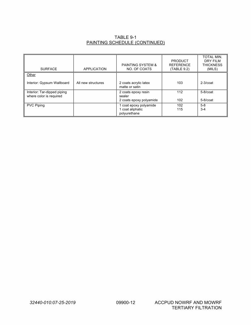
32440-010:07-25-2019 09900-12 ACCPUD NOWRF AND MOWRF TERTIARY FILTRATION
TABLE 9-1
PAINTING SCHEDULE (CONTINUED)
SURFACE APPLICATION PAINTING SYSTEM &
NO. OF COATS
PRODUCT REFERENCE (TABLE 9.2)
TOTAL MIN. DRY FILM
THICKNESS (MILS)
Other Interior: Gypsum Wallboard
All new structures
2 coats acrylic latex matte or satin
103
2-3/coat
Interior: Tar-dipped piping where color is required
2 coats epoxy resin sealer 2 coats epoxy polyamide
112
102
5-8/coat 5-8/coat
PVC Piping 1 coat epoxy polyamide 1 coat aliphatic polyurethane
102 115
5-8 3-4

32440-010:07-25-2019 09900-13 ACCPUD NOWRF AND MOWRF TERTIARY FILTERS DESIGN PROJECT
TABLE 9-2
PRODUCT LISTING
PRODUCT
REF. SYSTEM PURPOSE Tnemec Series PPG/AMERON CARBOLINE Sherwin-Williams
101 Acrylic filler Primer-sealer 130-6601 BLOXFIL 4000 Sanitile 100 Cement-Plex 875
102 Epoxy polyamide Finish coat semi-gloss or gloss N69 AMERLOCK 2 Carboguard 890 Dura-Plate 235
103 Acrylic latex Sealer 1028/1029 PITT TECH PLUS Carbocrylic 3359DTM
DTM Acrylic Primer/Finish
104 Epoxy Polyamide – metal
Primer 66 AMERCOAT 385 Carboguard 893SG Macropoxy 646
105 Epoxy Primer/Finish 20 AMERLOCK 2 Carboguard
561/56LT Macropoxy 646 PW
106 Coal tar epoxy Finish high-coat build 46H-413 AMERCOAT 78HB Bitumastic 300M Hi-Mil Sher Tar Epoxy
107 Coal tar Sealer 46-465 AMERCOAT 78HB Bitumastic 300M Hi-Mil Sher Tar Epoxy
108 Alkyd-medium oil Finish coat 2H DEVGUARD 4308 Carbocoat 8215 Industrial Enamel
109 Alkyd-long oil Finish coat 1029 DEVGUARD 4308 Carbocoat 8215 Industrial Enamel
110 Epoxy polyamide Primer 66-1211 AMERCOAT 385 Carboguard 893SG Macropoxy 646
112 Epoxy polyamide Sealer 66-1211 AMERCOAT 385 Carboguard 893SG Macropoxy 920 Pre-Prime
113 Urethane Barrier coat 530 AMERLOCK SEALER Rustbond --
114 Polyamine Epoxy Intermediate coat 27 AMERLOCK 385 Carboguard 893SG --
115 Aliphatic Polyurethane Finish coat 1074 or 1075 AMERCOAT 450 HS Carbothane 134HG Acrolon 218HS
116 Acrylic epoxy Finish coat 113 or 114 AQUAPON WB Sanitile 255 Water-Based Catalyzed
Epoxy
117 Epoxy block filler Sealer 1254 AMERLOCK 114 Sanitile 600 Kem Cati-Coat HS Epoxy Filler
118 Catalyzed epoxy Finish coat 84 AMERLOCK 2/400 Carboguard 890 Macropoxy 646
119 High solids epoxy Finish coat 104 AMERLOCK 400 Carboguard 890 Dura-Plate 235
120 Epoxy Top coat N69 AMERLOCK 2/400 Carboguard 890 --
- END OF SECTION -

32440-010:07-24-2019 11000-1 ACCPUD NOWRF AND MOWRF TERTIARY FILTRATION
SECTION 11000
EQUIPMENT GENERAL PROVISIONS PART 1 -- GENERAL 1.01 THE REQUIREMENT
A. The Contractor shall furnish, install, test, and place in acceptable operation all mechanical equipment and all necessary accessories as specified herein, as shown on the Drawings, and as required for a complete and operable system.
B. The mechanical equipment shall be provided complete with all accessories, special tools,
spare parts, mountings, and other appurtenances as specified, and as may be required for a complete and operating installation.
C. It is the intent of these Specifications that the Contractor shall provide the Owner complete
and operational equipment/systems. To this end, it is the responsibility of the Contractor to coordinate all interfaces with related mechanical, structural, electrical, instrumentation and control work and to provide necessary ancillary items such as controls, wiring, etc., to make each piece of equipment operational as intended by the Specifications.
D. The complete installation shall be free from excessive vibration, cavitation, noise, and oil or
water leaks. E. The requirements of this section shall apply to equipment furnished under Divisions 11, 13,
14, and 15. 1.02 REFERENCE SPECIFICATIONS, CODES, AND STANDARDS
A. All equipment, materials, and installations shall conform to the requirements of the most recent editions with latest revisions, supplements, and amendments of the specifications, codes, and standards listed in Section 01090, Reference Standards.
1.03 PERFORMANCE AFFIDAVITS
A. When required in the individual equipment Specifications, the Contractor shall submit manufacturer's Performance Affidavits for equipment to be furnished.
B. By these affidavits, each manufacturer must certify to the Contractor and the Owner, jointly,
that he has examined the Contract Documents and that the equipment, apparatus, or process he offers to furnish will meet in every way the performance requirements set forth or implied in the Contract Documents.
C. The Contractor must transmit to the Engineer three (3) original copies of the affidavit given
him by the manufacturer or supplier along with the initial Shop Drawing submittals. D. The Performance Affidavit must be signed by an officer of the basic corporation,
partnership, or company manufacturing the equipment and witnessed by a notary public.
01
27
16
BR

32440-010:07-24-2019 11000-2 ACCPUD NOWRF AND MOWRF TERTIARY FILTRATION
E. The Performance Affidavit shall have the following format:
Addressed to: (Contractor) and Athens-Clarke County PUD Reference: ACCPUD NOWRF AND MOWRF TERTIARY FILTERS PROJECT Text: (Manufacturer's Name) has examined the Contract Documents and hereby
state that the (Product) meets in every way the performance requirements set forth or implied in Section of the Contract Documents.
Signature: Corporate Officers shall be Vice President, or higher. (Unless statement
authorizing signature is attached.) 1.04 SHOP DRAWINGS
A. Shop Drawings shall be submitted to the Engineer for all equipment in accordance with Section 01300, Submittals and shall include the following information in addition to the requirements of Section 01300, Submittals:
1. Performance characteristics and descriptive data. 2. Detailed equipment dimensional drawings and setting plans. 3. General lifting, erection, installation, and adjustment instructions, and
recommendations. 4. Complete information regarding location, type, size, and length of all field welds in
accordance with "Standard Welding Symbols" AWS A2.0 of the American Welding Society. Special conditions shall be fully explained by notes and details.
5. The total uncrated weight of the equipment plus the approximate weight of shipped
materials. Support locations and loads that will be transmitted to bases and foundations. Exact size, placement, and embedment requirements of all anchor bolts.
6. Details on materials of construction of all components including applicable ASTM
designations. 7. Information on bearing types and bearing life. 8. Gear box design and performance criteria and AGMA service factor. 9. Piping schematics. 10. Motor data sheet indicating motor horsepower; enclosure type; voltage; insulation
class; temperature rise and results of dielectric tests; service-rating; rotative speed; motor speed-torque relationship; efficiency and power factor at ½, ¾, and full load; slip at full load; running, full load, and locked rotor current values; and safe running time-current curves.

32440-010:07-24-2019 11000-3 ACCPUD NOWRF AND MOWRF TERTIARY FILTRATION
11. Equipment and motor protective device details. Connection diagrams for motor and
all protective devices. 12. Equipment shop coating systems, interior and exterior. 13. Panel layout drawings, schematic wiring diagrams, and component product data
sheets for control panels. 14. A list of spare parts and special tools to be provided. 15. Any additional information required to show conformance with the equipment
specifications. 16. Warranty documentation including statement of duration of warranty period and
contact phone numbers and addresses for warranty issues. 1.05 OPERATION AND MAINTENANCE INSTRUCTION/MANUALS
A. Operation and Maintenance (O&M) manuals shall be submitted in accordance with Section 01300, Submittals.
B. O&M manuals shall include instructions, equipment ratings, technical bulletins, and any
other printed matter such as wiring diagrams and schematics, prints or drawings, containing full information required for the proper operation, maintenance, and repair of the equipment. Included in this submission shall be a spare parts diagram, complete spare parts list, bill of materials, OEM part numbers and manufacturer’s catalog information of all equipment components.
C. Each set of instructions shall be bound together in appropriate three-ring binders with a
detailed Table of Contents. D. Written operation and maintenance instructions shall be required for all equipment items
supplied for this project. The amount of detail shall be commensurate with the complexity of the equipment item.
E. Information not applicable to the specific piece of equipment installed on this project shall be
struck from the submission. F. Information provided shall include a source of replacement parts and names of service
representatives, including address and telephone number. G. Extensive pictorial cuts of equipment are required for operator reference in servicing. H. When written instructions include Shop Drawings and other information previously reviewed
by the Engineer, only those editions thereof which were approved by the Engineer, and which accurately depict the equipment installed, shall be incorporated in the instructions.

32440-010:07-24-2019 11000-4 ACCPUD NOWRF AND MOWRF TERTIARY FILTRATION
1.06 GENERAL INFORMATION AND DESCRIPTION
A. All parts of the equipment furnished shall, be designed and constructed for the maximum stresses occurring during fabrication, transportation, installation, testing, and all conditions of operation. All materials shall be new, and both workmanship and materials shall be entirely suitable for the service to which the units are to be subjected and shall conform to all applicable sections of these Specifications.
B. All parts of duplicate equipment shall be interchangeable without modification.
Manufacturer's design shall accommodate all the requirements of these Specifications. C. Equipment and appurtenances shall be designed in conformity with ASTM, ASME, AIEE,
NEMA, and other generally accepted applicable standards. D. All bearings and moving parts shall be adequately protected by bushings or other approved
means against wear, and provision shall be made for accessible lubrication by extending lubrication lines and fittings to approximately 30 inches above finished floor elevation.
E. Details shall be designed for appearance as well as utility. Protruding members, joints,
corners, gear covers, etc., shall be finished in appearance. All exposed welds on machinery shall be ground smooth and the corners of structural shapes shall be rounded or chamfered.
F. Machinery parts shall conform within allowable tolerances to the dimensions shown on the
working drawings. G. All machinery and equipment shall be safeguarded in accordance with the safety codes of
the USA and the State in which the project is located. H. All rotating shafts, couplings, or other moving pieces of equipment shall be provided with
suitable protective guards of sheet metal or wire mesh, neatly and rigidly supported. Guards shall be removable as required to provide access for repairs.
I. All equipment greater than 100 pounds shall have lifting lugs, eyebolts, etc., for ease of
lifting, without damage or undue stress exerted on its components. J. All manufactured items provided under this Section shall be new, of current manufacture,
and shall be the products of reputable manufacturers specializing in the manufacture of such products.
1.07 EQUIPMENT WARRANTIES
A. Warranty requirements may be added to or modified in the individual equipment specifications.
B. The equipment furnished under this Contract shall be guaranteed to be free from defects in
workmanship, design and/or materials for a period of one (1) year unless otherwise specified in the individual equipment specifications. The period of such warranties shall start on the date the particular equipment is placed in use by the Owner with corresponding start-up certification provided by the manufacturer’s technical representative as specified herein, provided that the equipment demonstrates satisfactory performance during the thirty-day operational period after the equipment startup. If the equipment does not perform

32440-010:07-24-2019 11000-5 ACCPUD NOWRF AND MOWRF TERTIARY FILTRATION
satisfactorily during the thirty-day operational period, the start of the warranty period will be delayed until the equipment demonstrates proper operation. The Equipment Supplier shall repair or replace without charge to the Owner any part of equipment which is defective or showing undue wear within the guarantee period, or replace the equipment with new equipment if the mechanical performance is unsatisfactory; furnishing all parts, materials, labor, etc., necessary to return the equipment to its specified performance level.
C. The Contractor shall provide an equipment warranty log book prepared specifically for this
project and submit two (2) copies of the document to the Engineer prior to final payment. The equipment warranty log book shall include a summary listing of all equipment warranties provided, date received, and start date and end date of warranty period. A copy of each equipment warranty and equipment start-up certification shall also be provided in the document.
D. The Equipment Supplier shall guarantee to the Owner that all equipment offered under
these specifications, or that any process resulting from the use of such equipment in the manner stated is not the subject of patent litigation, and that he has not knowingly offered equipment, the installation or use of which is likely to result in a patent controversy, in which the Owner as user is likely to be made the defendant.
Where patent infringements are likely to occur, each Equipment Supplier shall submit, as a part of his bid, license arrangements between himself, or the manufacturer of the equipment offered, and the patent owner or the controller of the patent, which will permit the use in the specified manner of such mechanical equipment as he may be bidding. Each Equipment Supplier, by submitting his bid, agrees to hold and save the Owner and Engineer or its officers, agents, servants, and employees harmless from liability of any nature or kind, including cost and expenses for, or on account of, any patented or unpatented invention, process, article, or appliance manufactured or used in the performance of the work under this contract, including the use of the same by the Owner.
PART 2 -- PRODUCTS 2.01 ACCEPTABLE MANUFACTURERS
A. The materials covered by these Specifications are intended to be equipment of proven reliability, and as manufactured by reputable manufacturers having experience in the production of such equipment. The Contractor shall, upon request of the Engineer, furnish the names of not less than 5 successful installations of the manufacturer's equipment of the same size and model of that offered under this contract. The equipment furnished shall be designed, constructed, and installed in accordance with the industry accepted practices and shall operate satisfactorily when installed as shown on the Drawings and operated per manufacturer's recommendations.
2.02 ANCHORS AND SUPPORTS
A. The Contractor shall furnish, install, and protect all necessary guides, bearing plates, anchor and attachment bolts, and all other appurtenances required for the installation of the devices included in the equipment specified. Working Drawings for installation shall be furnished by

32440-010:07-24-2019 11000-6 ACCPUD NOWRF AND MOWRF TERTIARY FILTRATION
the equipment manufacturer, and suitable templates shall be used by the Contractor when required in the detailed equipment Specifications.
B. Anchor bolts and fasteners shall be furnished in accordance with Section 05050, Metal
Fastening, and with the individual equipment Specifications. All anchor bolts shall be a minimum of 1/2-inch diameter. All anchor bolts, handrail bolts, washers, clips, clamps, and fasteners of any type shall be constructed of 316 stainless steel, unless otherwise specified the individual equipment Specifications.
C. The Contractor shall provide all concrete pads or pedestals required for equipment
furnished. All concrete equipment pads shall be a minimum of 6” high, unless otherwise shown on the Drawings and shall be doweled.
D. Pipe sleeves or other means of adjusting anchor bolts shall be provided where indicated or
required. Equipment shall be leveled by first using sitting nuts on the anchor bolts, and then filling the space between the equipment base and concrete pedestal with non-shrink grout, unless alternate methods are recommended by the manufacturer and are acceptable to the Engineer (such as shim leveling pumps, or chemical grout). Non-shrink grout shall be as specified in Section 03600, Grout.
2.03 STRUCTURAL STEEL
A. Structural steel used for fabricating equipment shall conform to the requirements of Section 05120, Structural Steel.
B. All materials shall conform to applicable provisions of the AISC Specifications for the design
and fabrication of structural steel, and to pertinent ASTM Standard Specifications.
2.04 DISSIMILAR METALS
A. All dissimilar metals shall be properly isolated to the satisfaction of the Engineer. 2.05 GALVANIZING
A. Where required by the equipment specifications, galvanizing shall be performed in accordance with Section 05035, Galvanizing.
2.06 STANDARDIZATION OF GREASE FITTINGS
A. The grease fittings on all mechanical equipment shall be such that they can be serviced with a single type of grease gun. Fittings shall be “Zerk” type.
2.07 ELECTRICAL REQUIREMENTS
A. All electrical equipment and appurtenances, including but not limited to motors, panels, conduit and wiring, etc., specified in the equipment specifications shall comply with the applicable requirements of the Division 16 specifications and the latest National Electric Code.

32440-010:07-24-2019 11000-7 ACCPUD NOWRF AND MOWRF TERTIARY FILTRATION
B. Motors shall conform to the applicable requirements of Section 15170, Electric Motors. Medium voltage motors shall conform to the applicable requirements of Section 15171, Medium Voltage Electric Motors.
C. In the individual equipment specifications, specified motor horsepower is intended to be the
minimum size motor to be provided. If a larger motor is required to meet the specified operating conditions and performance requirements, the Contractor shall furnish the larger sized motor and shall upgrade the electrical service (conduit, wires, starters, etc.) at no additional cost to the Owner.
D. Where variable frequency drives (VFDs) are specified, the Contractor shall be responsible
for coordinating between equipment supplier and VFD supplier to ensure a complete and operational system. VFDs shall be furnished under Division 16 and shall be as specified in Section 16495, Variable Frequency Drive Systems.
E. Motor starters and controls shall be furnished and installed under Division 16 and Division
17 unless otherwise specified in the individual pump specifications. 2.08 ACCESSORIES, SPARE PARTS, AND SPECIAL TOOLS
A. Spare parts for equipment shall be furnished where indicated in the equipment Specifications or where recommended by the equipment manufacturer.
B. Spare parts shall be identical and interchangeable with original parts. C. The spare parts shall be packed in containers suitable for long term storage, bearing labels
clearly designating the contents and the pieces of equipment for which they are intended. D. Painting requirements for spare parts shall be identical to those for original, installed parts.
Where no painting or protective coating is specified, suitable provisions shall be made to protect against corrosion.
E. Spare parts shall be delivered at the same time as the equipment to which they pertain.
Spare parts shall be stored separately in a locked area, maintained by the Contractor, and shall be turned over to the Owner in a group prior to substantial completion. All of these materials shall be properly packed, labeled, and stored where directed by the Owner and Engineer.
F. The Contractor shall furnish all special tools necessary to operate, disassemble, service,
repair, and adjust the equipment in accordance with the manufacturer’s operation and maintenance manual.
G. The Contractor shall furnish a one-year supply of all recommended lubricating oils and
greases. The manufacturer shall submit a list of at least four manufacturer's standard lubricants which may be used interchangeably for each type of lubricant required. All of these materials shall be properly packed, labeled and stored where directed by the Engineer.

32440-010:07-24-2019 11000-8 ACCPUD NOWRF AND MOWRF TERTIARY FILTRATION
2.09 EQUIPMENT IDENTIFICATION
A. All mechanical equipment shall be provided with a substantial stainless steel nameplate, mechanically fastened with stainless steel hardware in a conspicuous place, and clearly inscribed with the manufacturer's name, year of manufacture, serial number, and principal rating data.
B. Each pump and other piece of mechanical equipment shall also be identified as to name
and number by a suitable laminated plastic or stainless steel nameplate mechanically fastened with stainless steel hardware; for example, "Raw Water Pump #1". Coordinate name and number with same on remotely located controls, control panel, and other related equipment.
C. Nameplates shall not be painted over.
PART 3 -- EXECUTION 3.01 SHOP TESTING
A. All equipment shall be tested in the shop of the manufacturer in a manner which shall conclusively prove that its characteristics comply fully with the requirements of the Contract Documents and that it will operate in the manner specified or implied.
B. No equipment shall be shipped to the project until the Engineer has been furnished a
certified copy of test results and has notified the Contractor, in writing, that the results of such tests are acceptable.
C. Five (5) certified copies of the manufacturer's actual test data and interpreted results thereof
shall be forwarded to the Engineer for review. D. If required by the individual equipment Specifications, arrangements shall be made for the
Owner/Engineer to witness performance tests in the manufacturer's shop. The Engineer shall be notified ten working days before shop testing commences. Expenses are to be paid by Contractor.
E. Shop testing of electric motors shall be in accordance with applicable requirements of
Section 15170, Electric Motors; Section 15171, Medium Voltage Electric Motors, and Section 16000, Basic Electrical Requirements.
3.02 STORAGE OF EQUIPMENT AND MATERIALS
A. Contractor shall store his equipment and materials at the job site in strict accordance with the manufacturer's recommendations and as directed by the Owner or Engineer, and in conformity to applicable statutes, ordinances, regulations, and rulings of the public authority having jurisdiction. Equipment and materials shall not be delivered to the site prior to 90 days in advance of the scheduled installation. Partial payment requests will not be processed for materials delivered prior to 90 days before installation or for materials that are not properly stored.

32440-010:07-24-2019 11000-9 ACCPUD NOWRF AND MOWRF TERTIARY FILTRATION
B. Material or equipment stored on the job site is stored at the Contractor's risk. Any damage sustained of whatever nature shall be repaired to the Engineer's satisfaction at no expense to the Owner. Stored electrical equipment is to be protected from the elements and shall have space heaters energized.
C. Contractor shall not store unnecessary materials or equipment on the job site and shall take
care to prevent any structure from being loaded with a weight which will endanger its security or the safety of persons.
D. Contractor shall observe all regulatory signs for loadings on structures, fire safety, and
smoking areas. E. Contractor shall not store materials or encroach upon private property without the written
consent of the owners of such private property. 3.03 MANUFACTURER’S FIELD SERVICES
A. The Contractor shall arrange for a qualified Technical Representative from each manufacturer or supplier of equipment who is regularly involved in the inspection, installation, start-up, troubleshooting, testing, maintenance, and operation of the specified equipment. Qualification of the Technical Representative shall be appropriate to the type of equipment furnished and subject to the approval of the Engineer and the Owner. Where equipment furnished has significant process complexity, furnish the services of engineering personnel knowledgeable in the process involved and the function of the equipment. When necessary, the Contractor shall schedule multiple Technical Representatives to be present at the same time for the purpose of coordinating the operation of multiple pieces of related equipment.
B. For each site visit, the Technical Representative shall submit jointly to the Owner, the
Engineer, and the Contractor a complete signed report of the results of his inspection, operation, adjustments, and testing. The report shall include detailed descriptions of the points inspected, tests and adjustments made, quantitative results obtained if such are specified.
C. The manufacturer's Technical Representative shall provide the following services.
1. Installation: The Technical Representative shall inspect the installed equipment to
verify that installation is in accordance with the manufacturer’s requirements. Where required by individual equipment specifications, the Technical Representative shall also supervise the installation of the equipment.
2. Testing: After installation of the equipment has been completed and the equipment
is presumably ready for operation, but before it is operated by others, the Technical Representative shall inspect, operate, test, and adjust the equipment as required to prove that the equipment is in proper condition for satisfactory operation under the conditions specified. Unless otherwise noted in the signed site visit report, the report shall constitute a certification that the equipment conforms to the requirements of the Contract and is ready for startup and that nothing in the installation will render the manufacturer's warranty null and void. The report shall include date of final acceptance field test, as well as a listing of all persons present during tests.

32440-010:07-24-2019 11000-10 ACCPUD NOWRF AND MOWRF TERTIARY FILTRATION
3. Startup: The Technical Representative shall start up the equipment for actual
service with the help of the Contractor. In the event that equipment or installation problems are experienced, the Contractor and the representative shall provide the necessary services until the equipment is operating satisfactorily and performing according to the specifications at no additional cost to the Owner. Unless otherwise noted in the signed site visit report, the report shall constitute a certification that the equipment conforms to the requirements of the Contract and is ready for permanent operation and that nothing in the installation will render the manufacturer's warranty null and void.
4. Training: The Technical Representative shall instruct the Owner's operating
personnel in correct operation and maintenance procedures. The instruction shall demonstrate start-up, operation, control, adjustment, troubleshooting, servicing, maintenance, and shutdown of each item of equipment. Such instruction shall be scheduled at a time arranged with the Owner at least 2 weeks in advance of the training and shall be provided while the respective Technical Representative's equipment is fully operational. The Contractor shall have submitted, and had accepted, the O&M Manuals prior to commencement of training. Training shall be provided to three separate shifts of the Owner's personnel between the hours of 8:00 A.M. and 6:00 P.M. as necessary. The Contractor shall provide professional video taping of all training sessions. Completed, labeled tapes shall be provided to the Owner for each type of training session.
5. Services after Startup: Where required by the individual equipment specifications,
the Technical Representative shall return to the project site thirty (30) days after the start update to review the equipment performance, correct any equipment problems, and conduct operation and maintenance classes as required by the Owner. This follow-up trip is required in addition to the specified services of Technical Representative prior to and during equipment startup. At this time, if there are no equipment problems, each manufacturer shall certify to the Owner in writing that his equipment is fully operational and capable of meeting operating requirements. If the equipment is operating incorrectly, the Technical Representative will make no certification to the Owner until the problems are corrected and the equipment demonstrates a successful thirty (30) days operating period.
D. Services of the Technical Representative will require a minimum of two (2) site visits, one
for installation and testing and one for startup and training, and will be for the minimum number of days recommended by the manufacturer and approved by the Engineer but will not be less than the number of days specified in individual equipment sections.
E. The Contract amount shall include the cost of furnishing the Technical Representative for
the minimum number of days specified, and any additional time required to achieve successful installation and operation. The times specified for services by the Technical Representative in the equipment Specifications are exclusive of travel time to and from the facility and shall not be construed as to relieve the manufacturer of any additional visits to provide sufficient service to place the equipment in satisfactory operation.
F. The Contractor shall notify the Engineer at least 14 days in advance of each equipment test
or Owner training session.

32440-010:07-24-2019 11000-11 ACCPUD NOWRF AND MOWRF TERTIARY FILTRATION
G. The Technical Representative shall sign in and out at the office of the Engineer's Resident Project Representative on each day he is at the project.
3.04 INSTALLATION
A. The Contractor shall obtain written installation manuals from the equipment manufacturer prior to installation. Equipment shall be installed strictly in accordance with recommendations of the manufacturer. A copy of all installation instructions shall be furnished the Engineer's field representative one week prior to installation.
B. The Contractor shall have on hand sufficient personnel, proper construction equipment, and
machinery of ample capacity to facilitate the work and to handle all emergencies normally encountered in work of this character. To minimize field erection problems, mechanical units shall be factory-assembled insofar as practical.
C. Equipment shall be erected in a neat and workmanlike manner on the foundations at the
locations and elevations shown on the Drawings. D. All equipment sections and loose items shall be match-marked prior to shipping. E. For equipment such as pumping units, which require field alignment and connections, the
Contractor shall provide the services of the manufacturer's qualified mechanic, millwright, or machinist, to align the pump and motor prior to making piping connections or anchoring the pump base. Alignment shall be as specified herein.
F. The Contractor shall furnish oil and grease for initial operation and testing. The
manufacturer and grades of oil and grease shall be in accordance with the recommendations of the equipment manufacturer.
3.05 ALIGNMENT A. Set equipment to dimensions shown on drawings. Dimensions shall be accurate to +/- 1/16
inch unless otherwise noted on the drawings. Wedges shall not be used for leveling, aligning, or supporting equipment.
B. General Equipment Leveling: Non-rotating equipment shall be set level to +/- 1/16 inch per
10 foot length (.005 inch per foot) unless otherwise noted on the drawings. Shims shall be used unless equipment is furnished with leveling feet. Set shims flush with equipment baseplate edges. When grouting is required, equipment shall be shimmed to allow a minimum of one inch grout thickness. Grout shall cover shims at least 3 inches. Final level check shall be held for inspection and approval by Engineer before proceeding.
C. Grouting
1. Fill anchor bolt holes or sleeves with grout, after bolt alignment is proven, and prior
to placing grout under equipment bases. 2. Surface Preparation. Roughen surface by chipping, removing laitance, and
unsound concrete. Clean area of all foreign material such as oil, grease, and scale.

32440-010:07-24-2019 11000-12 ACCPUD NOWRF AND MOWRF TERTIARY FILTRATION
Saturate area with water at least 4 hours prior to grouting, removing excess water ponds.
3. Application. Place grout after the equipment base has been set and its alignment
and level have been approved. Form around the base, mix grout, and place in accordance with the grout manufacturers published instructions. Eliminate all air or water pockets beneath the base using a drag chain or rope.
4. Finishing. Point the edges of the grout to form a smooth 45 degree slope. 5. After grout has cured (not before 3 days after placement) paint exposed surfaces of
grout with shellac. 6. Level Verification. After grout has cured, and immediately prior to drive alignment,
recheck equipment for level and plumb. Re-level and square as necessary. Hold final checks for inspection and approval by Engineer.
D. Inspect for and remove all machining burrs or thread pulls in female holes on mating
surfaces of mounting frame and machine feet. E. Inspect and clean equipment mounting base pads, feet, and frames to remove all grease,
rust, paint and dirt. F. Assembled equipment shafts shall be set level to .0015 inches per foot of shaft length (+/-
.0005 inches) up to a maximum of 0.015 inches for any length shaft unless the manufacturers requirements are more stringent or unless otherwise noted in the equipment specifications. Use the machined surfaces on which the equipment sets for the base/mounting frame leveling plane. Use the machined shaft surface for equipment leveling plane.
G. Sprocket and Sheave Alignment. Check shaft mounted components for face runout and
eccentricity (outside diameter) runout by magnetically mounting a dial indicator on a stationary base and indicating over 360 degrees on a continuous machined surface at the outside diameter of the component. Maximum allowable total indicated face runout and eccentricity for sprockets and sheaves will be per ANSI Standard B29.1-1975.
H. Belt tensioning. Set drive belt tension to manufacturer's specification for the belt type.
Recheck alignment after drive tensioning. I. Thermal/Mechanical Growth. Thermal/mechanical growth corrections for driver and driven
machines will be used in vertical and horizontal alignment where applicable. The equipment manufacturer will determine thermal/mechanical growth applicability for any machine and provide the correction offsets to be used.
J. Rotating Shaft Alignment
1. Fixtures will be set up on the driver and driven machine, machines shaft surfaces.
Machined coupling hubs may be used only if there is no clearance to mount fixtures directly on the shafts.

32440-010:07-24-2019 11000-13 ACCPUD NOWRF AND MOWRF TERTIARY FILTRATION
2. Primary alignment method for direct drive machines is when coupled. Uncoupled alignment will be used only when approved by the Engineer.
3. Account for possible coupling flex by always rotating coupled machines in the same
direction during alignment. 4. Uncoupled machines must be connected so that both shafts turn together without
relative motion during alignment. 5. Indicator bar sag will be measured and included for each reverse indicator alignment
setup. 6. Reverse Dial Indicator. The final maximum allowable misalignment: vertical and
horizontal from the desired targets of .000 inches (for a non-thermal growth machine) or from the given target readings (for a thermal growth machine) must meet BOTH of the following conditions simultaneously: 1/2 the final total indicator reading at each indicator will be no more than shown in the table below AND the final remaining correction at each machine foot be no more than .001 inches of required movement.
Machine Speed (RPM) Total Misalignment* (inches)
Up to 1800 .002
1800 and greater .001
* 1/2 indicator reading
3.06 FIELD TESTING
A. All equipment shall be set, aligned and assembled in conformance with the manufacturer's drawings and instructions. Provide all necessary calibrated instruments to execute performance tests. Submit report certified by the pump manufacturer’s representative.
B. Preliminary Field Tests, Yellow Tag
1. As soon as conditions permit, after the equipment has been secured in its
permanent position, the Contractor shall:
a. Verify that the equipment is free from defects. b. Check for alignment as specified herein. c. Check for direction of rotation. d. Check motor for no load current draw.
2. Contractor shall flush all bearings, gear housings, etc., in accordance with the
manufacturer's recommendations, to remove any foreign matter accumulated during shipment, storage or erection. Lubricants shall be added as required by the manufacturer's instructions.

32440-010:07-24-2019 11000-14 ACCPUD NOWRF AND MOWRF TERTIARY FILTRATION
3. When the Contractor has demonstrated to the Engineer that the equipment is ready for operation, a yellow tag will be issued. The tag will be signed by the Engineer, or his assigned representative and attached to the equipment. The tag shall not be removed.
4. Preliminary field tests, yellow tag, must be completed before equipment is subjected
to final field tests, blue tag.
C. Final Field Tests, Blue Tag
1. Upon completion of the above, and at a time approved by the Engineer, the equipment will be tested by operating it as a unit with all related piping, ducting, electrical and controls, and other ancillary facilities.
2. The equipment will be placed in continuous operation as prescribed or required and
witnessed by the Engineer or his assigned representative and the Owner or his assigned representative.
3. The tests shall prove that the equipment and appurtenances are properly installed,
meet their operating cycles and are free from defects such as overheating, overloading, and undue vibration and noise. Operating field tests shall consist of the following:
a. Check equipment for excessive vibration and noise as specified herein. b. Check motor current draw under load conditions. The rated motor
nameplate current shall not be exceeded. c. Recheck alignment with dial indicators where applicable, after unit has run
under load for a minimum of 24 hours.
D. In addition to the above described field tests, any other tests specifically required by Section 11100, Pumps-General, the individual equipment Specifications, or by the manufacturer shall be performed.
E. Until final field tests are acceptable to the Engineer, the Contractor shall make all necessary
changes, readjustments and replacements at no additional cost to the Owner. F. Upon acceptance of the field tests, a blue tag will be issued. The tag will be signed by the
Engineer and attached to the unit. The tag shall not be removed and no further construction work will be performed on the unit, except as required during start-up operations and directed by the Engineer.
G. Defects which cannot be corrected by installation adjustments will be sufficient grounds for
rejection of any equipment. H. All costs in connection with field testing of equipment such as lubricants, temporary
instruments, labor, equipment, etc., shall be borne by the Contractor. Power, fuel, chemicals, water, etc. normally consumed by specific equipment shall be supplied by the Owner unless otherwise specified in the individual equipment specifications.

32440-010:07-24-2019 11000-15 ACCPUD NOWRF AND MOWRF TERTIARY FILTRATION
I. The Contractor shall be fully responsible for the proper operation of equipment during tests and instruction periods and shall neither have nor make any claim for damage which may occur to equipment prior to the time when the Owner formally takes over the operation thereof.
J. Field testing of electric motors shall be in accordance with Section 15170, Electric Motors;
Section 15171, Medium Voltage Electric Motors, and Section 16000, Basic Electrical Requirements.
3.07 VIBRATION TESTING
A. Unless specified otherwise in the detailed equipment specifications, each pump, blower, compressor, motor or similar item of stationary rotating equipment having a rated power in excess of 40HP shall be tested after installation for acceptable vibration levels.
B. Vibration testing shall be performed by an experienced factory-trained and authorized third-
party analysis expert (not a sales representative) retained by the Contractor and approved by the Engineer. Each unit or pump system shall be tested separately without duplicate equipment running. All field testing shall be done in the presence of the Engineer. The Engineer shall be furnished with four (4) certified copies of vibration test data for each test performed.
C. For systems with variable speed drives, tests shall be conducted at various speeds between
maximum and minimum. For systems with two-speed drives, tests shall be conducted at both speeds. For systems with constant-speed drive, tests shall be conducted under various loading conditions as determined by the Engineer.
D. All field vibration tests shall be performed with the equipment operating on the product for
which it is intended, or a substitute acceptable to the Engineer. E. The term displacement, as used herein, shall mean total peak-to-peak movement of
vibrating equipment, in mils; velocity or speed of the vibration cycle, measured in G's. Displacement and velocity shall be measured by suitable equipment equal to IRD Mechanalysis, Bentley, Nevada.
E. Frequency of vibration, in cycles per minute (cpm), shall be determined when vibration
exceeds specified levels or as otherwise necessary. Vibration shall be measured on the bearing housing, unless other locations are deemed necessary by the vibration analysis expert and Engineer.
F. For all equipment tested, vibration shall be checked in the radial and axial directions.
Unless otherwise specified elsewhere, axial vibration shall not exceed 0.1 in/sec; and radial vibration shall not exceed 0.2 in/sec. For pumps radial vibration shall not exceed that permitted by the Hydraulic Institute Standards except that, at vibration frequencies in excess of 8,000 cpm, the velocity shall not exceed 0.2 in/sec.
G. Copies of test results shall be submitted to the Engineer for review. Should the vibration
field test results exceed shop test results, the manufacturer’s recommendations, or the limits specified herein, the Contractor shall correct the deficiencies within thirty (30) days. After corrections have been completed, the vibration testing shall be re-run and the results re-submitted to the Engineer for review.

32440-010:07-24-2019 11000-16 ACCPUD NOWRF AND MOWRF TERTIARY FILTRATION
H. Noise or vibration in any rotating equipment which the Engineer judges to be excessive or
damaging, shall be cause for rejection. 3.08 FAILURE OF EQUIPMENT TO PERFORM
A. Any defects in the equipment, or failure to meet the guarantees or performance requirements of the Specifications shall be promptly corrected by the Contractor by replacements or otherwise.
B. If the Contractor fails to make these corrections, or if the improved equipment shall fail again
to meet the guarantees or specified requirements, the Owner, notwithstanding his having made partial payment for work and materials which have entered into the manufacture of said equipment, may reject said equipment and order the Contractor to remove it from the premises at the Contractor's expense.
C. The Contractor shall then obtain specified equipment to meet the contract requirements or
upon mutual agreement with the Owner, adjust the contract price to reflect not supplying the specific equipment item.
D. In case the Owner rejects said equipment, then the Contractor hereby agrees to repay to
the Owner all sums of money paid to him for said rejected equipment on progress certificates or otherwise on account of the lump sum prices herein specified.
E. Upon receipt of said sums of money, the Owner will execute and deliver to the Contractor a
bill of sale of all his rights, title, and interest in and to said rejected equipment; provided, however, that said equipment shall not be removed from the premises until the Owner obtains from other sources other equipment to take the place of that rejected.
F. Said bill of sale shall not abrogate Owner's right to recover damages for delays, losses, or
other conditions arising out of the basic contract. 3.09 PAINTING
A. All surface preparation, shop painting, field repairs, finish painting, and other pertinent detailed painting specifications shall conform to applicable sections of Section 09900, Painting.
B. All shop coatings shall be compatible with proposed field coatings. C. All inaccessible surfaces of the equipment, which normally require painting, shall be finished
painted by the manufacturer. The equipment and motor shall be painted with a high quality epoxy polyamide semi-gloss coating specifically resistant to chemical, solvent, moisture, and acid environmental conditions, unless otherwise specified.
D. Gears, bearing surfaces, and other unpainted surfaces shall be protected prior to shipment
by a heavy covering of rust-preventive compound sprayed or hand applied which shall be maintained until the equipment is placed in operation. This coating shall be easily removable by a solvent.
3.10 WELDING

32440-010:07-24-2019 11000-17 ACCPUD NOWRF AND MOWRF TERTIARY FILTRATION
A. The Equipment Manufacturer's shop welding procedures, welders, and welding operators
shall be qualified and certified in accordance with the requirement of AWS D1.1 "Structural Welding Code - Steel" or AWS D1.2 "Structural Welding Code - Aluminum" of the American Welding Society, as applicable.
B. The Contractor's welding procedures, welders, and welding operators shall be qualified and
certified in accordance with the requirements of AWS D1.1 "Structural Welding Code - Steel" or AWS D1.2 "Structural Welding Code - Aluminum" of the American Welding Society, as applicable.
C. The Contractor shall perform all field welding in conformance with the information shown on
the Equipment Manufacturer's drawings regarding location, type, size, and length of all welds in accordance with "Standard Welding Symbols" AWS A2.0 of the American Welding Society, and special conditions, as shown by notes and details.
- END OF SECTION -

32440-010:07-24-2019 11100-1 ACCPUD NOWRF AND MOWRF TERTIARY FILTRATION
SECTION 11100
PUMPS - GENERAL PART 1 -- GENERAL 1.01 THE REQUIREMENT
A. The Contractor shall furnish, install, test, and make fully operational all pumping equipment, complete with all necessary accessories, in compliance with the Contract Documents.
B. All pumping equipment shall be provided in accordance with the requirements of Section
11000, Equipment General Provisions. C. The provisions of this section shall apply to all pumps and pumping equipment specified
except where specifically noted otherwise in the Contract Documents.
D. The pumps shall be provided complete with all accessories, shims, sheaves, couplings, and other appurtenances as specified, and as may be required for a complete and operating installation.
1.02 SHOP DRAWINGS
A. Shop Drawings shall include the following information in addition to the requirements of Section 01300, Submittals and Section 11000, Equipment General Provisions.
1. Details of shaft sealing system 2. Pump performance curves at rated speed and reduced speed (if reduced speeds
are specified). Curves shall indicate flow, head, efficiency, brake horsepower, NPSH required, and minimum submergence. Curves shall include limits (minimum and maximum flows) for stable operation without cavitation, overheating, recirculation, or excessive vibration.
3. General cutaway sections, materials, dimension of shaft projections, shaft and
keyway dimensions, shaft diameter, dimension between bearings, general dimensions of pump, suction head bolt orientation, and anchor bolt locations and forces.
4. Foundry certificates and results of Brinnell hardness testing showing compliance to
ASTM A 532 (where required in the individual pump specifications). 5. Submersible pump submittals shall also include:
a. Product data sheets for power and control cables and length of cables. b. Details on pump guide rail system and mounting requirements.
09
08
15
8B
R

32440-010:07-24-2019 11100-2 ACCPUD NOWRF AND MOWRF TERTIARY FILTRATION
PART 2 -- PRODUCTS 2.01 MATERIALS
A. All materials employed in the pumping equipment shall be suitable for the intended application. Material not specifically called for shall be high-grade, standard commercial quality, free from all defects and imperfection that might affect the serviceability of the product for the purpose for which it is intended, and shall conform to the following requirements unless otherwise specified in individual pumping equipment Specifications:
1. Cast iron pump casings and bowls shall be of close-grained gray cast iron,
conforming to ASTM A 48, or equal. 2. Bronze pump impellers shall conform to ASTM B 584, “G” bronze. 3. Stainless steel pump shafts shall be of Type 400, Series. Miscellaneous stainless
steel parts shall be of Type 316.
B. Suction and discharge flanges shall conform to ANSI standard B16.1 or B16.5 dimensions.
C. Handholes on pump casings shall be shaped to follow the contours of the casing to avoid any obstructions in the water passage.
2.02 APPURTENANCES
A. Pressure Gauges
1. The Contractor shall furnish and install pressure gauges on the suction and discharge of each pump, except wet-pit submersible pumps and vertical turbine pumps.
2. The Contractor shall furnish and install pressure gauges on the discharge piping of
each wet-pit submersible pump and vertical turbine pump in the locations shown on the Drawings or as directed by the Engineer.
3. Suction gauges shall be of the single scale compound type to indicate both pressure
and vacuum. Each suction gauge shall be graduated in feet of water over the span of 34 feet below and above zero.
4. Discharge gauges shall be graduated in feet from zero to a minimum of five (5) feet
of water above the respective pump shutoff head or to a minimum of 30% above the maximum operation pressure, whichever is greater. Graduation shall be in feet of water.
5. All gauges shall be supplied by one manufacturer and shall be as specified in
Section 17650, Pressure Gauges. 6. All gauges shall be provided with diaphragm seals or isolating ring seals as
specified in Section 17698, Instrumentation and Control Accessories.

32440-010:07-24-2019 11100-3 ACCPUD NOWRF AND MOWRF TERTIARY FILTRATION
B. Flexible couplings for direct driven pumps shall be as manufactured by Falk, Dodge, Woods Corp., or equal and shall be furnished with guards in accordance with OSHA Rules and Regulations. Spacer couplings shall be provided where necessary to allow removal of the pump rotating element without disturbing the driver.
2.02 ELECTRICAL REQUIREMENTS
A. All pumps shall be furnished with motors such that the motor shall not be overloaded throughout the full range of the pump operation, unless otherwise specifically approved by the Engineer.
B. Where variable frequency drives (VFDs) are specified, the Contractor shall be responsible
for coordinating between pump supplier and VFD supplier to ensure a complete and operational system. VFDs shall be furnished under Division 16 and shall be as specified in Section 16495, Low Voltage Variable Frequency Drive Systems.
C. Motor starters and controls shall be furnished and installed under Division 16 and Division
17 unless otherwise specified in the individual pump specifications. 2.03 EQUIPMENT IDENTIFICATION
A. In addition to the requirements of Section 11000, Equipment General Provisions, nameplate data for each pump shall include the rating in gallons per minute, rated head, speed, and efficiency at the primary design point.
PART 3 -- EXECUTION 3.01 INSTALLATION
A. Drains: All gland seals, air valves, and drains shall be piped to the nearest floor drain or trench drain with galvanized steel pipe or copper tube, properly supported with brackets.
B. Solenoid Valves: Where required, the pump manufacturer shall furnish and install solenoid
valves on the water or oil lubrication lines. Solenoid valve electrical rating shall be compatible with the motor control voltage and shall be furnished complete with all necessary conduit and wiring installation from control panel to solenoid.
3.02 SHOP TESTING
A. Shop tests shall be performed in accordance with Section 11000, Equipment General Provisions, and except where stated otherwise herein, shall be conducted in accordance with the latest version of Hydraulic Institute Standard 14.6, Hydraulic Performance Acceptance Tests.
B. Pump testing shall be witnessed by the Owner/Engineer where specified in the individual
pump specifications. The testing procedure shall be submitted to the Engineer for review before scheduling the testing. The Engineer shall be given at least 2 weeks advanced notice of the scheduled testing date.

32440-010:07-24-2019 11100-4 ACCPUD NOWRF AND MOWRF TERTIARY FILTRATION
C. Certified test curves for shall be provided for all centrifugal pumps unless otherwise specified in the individual pump specifications. Certified tests will not be required for submersible sump pumps (as specified in Sections 11133 and 11136) with motors less than 5 hp.
D. Pumps shall be within the tolerances specified for Acceptance Grade 1U, in accordance
with the latest version of Hydraulic Institute Standards 14.6. E. For wet pit submersible pumps and vertical turbine pumps, all tests shall be run at minimum
pump submergence specified in the individual pump specifications. F. Where required in the individual pump specifications, each individual casting shall be
Brinnell tested in a minimum of two places, in an area of representative casting thickness to ASTM Method E-10. Results shall be certified by a registered professional ENGINEER. Test results shall verify the satisfaction of the required Brinnell hardness of the finished product as specified in respective subsections.
3.03 FIELD TESTING
A. Field tests shall be performed in accordance within Section 11000, Equipment General Provisions and additionally as specified below and in the individual pump specifications.
B. Final acceptance tests shall demonstrate the following:
1. The pumps have been properly installed and are in proper alignment.
2. The pumps operate without overheating or overloading of any parts and without
objectionable vibration. Vibration shall be within the Hydraulic Institute limits, or manufacturer's limits if more stringent.
3. The pumps can meet the specified operating conditions. All pumps shall be
checked at maximum speed for a minimum of four points on the pump curve for capacity, head, and amperage. The rated motor nameplate current shall not be exceeded at any point. Pumps with drive motors rated at less than five horsepower shall only be tested for overcurrent when overheating or other malfunction becomes evident in general testing.
- END OF SECTION -

32440-010:08-05-2019 11360-1 ACCPUD NOWRF AND MOWRFTERTIARY FILTRATION
SECTION 11360
DISK FILTRATION SYSTEM
PART 1 -- GENERAL
1.01 THE REQUIREMENT
A. The Contractor shall furnish, install, test, and place into operation a complete and operational disk filtration system. The system shall consist of three disk filter units consisting of inlet and effluent weir assembly, mounting brackets and hardware, center tube installation with cloth media disks and drives, backwash and sludge discharge assemblies, valves, instrumentation, controls as specified herein and as shown on the Drawings, and any other components necessary for a complete and operable system. Each unit shall be complete and operational and will run in parallel operation to the other units. The filter system shall be designed to operate on a continuous basis while receiving varying flows.
B. Each filter unit shall be used to filter secondary effluent containing up to 30 mg/liter of total suspended solids to provide treatment to the effluent standards listed in this specification.
C. Filter system manufacturers shall guarantee that the filter system is capable of meeting the specified performance and design criteria and requirements for the wastewater characteristics specified herein.
1.02 REFERENCE SPECIFICATIONS, CODES AND STANDARDS
A. Reference Specifications, Codes and Standards shall be as specified in Section 01091, Codes and Standards, Section 11000, Equipment General Provisions, and Division 16, Electrical.
1.03 SUBMITTALS
A. The Contractor shall submit complete Shop Drawings, Operation and Maintenance Instructions and other information as required for the Disk Filters and all equipment specified herein in accordance with Section 11000, Equipment General Provisions, and Section 01340, Submittals, Shop Drawings, Product Data and Samples.
B. Shop Drawings shall include full descriptive information of materials used, method of fabrication, sizes, enclosures, ratings and layout dimensions, etc. to demonstrate full compliance with the Contract Documents.
C. Shop Drawings shall include weights of all system components and the total weight of each component of the disk filter unit.
D. A complete description of the protective coating system to be used on all components, prior to shipment and after installation shall be submitted with the Shop Drawings.

32440-010:08-05-2019 11360-2 ACCPUD NOWRF AND MOWRFTERTIARY FILTRATION
E. Field installation information, including anchor bolt pattern, tie-in locations for influent, filtered effluent, backwash, power and control, access, and approximate total weight of each equipment piece, shall be submitted with the Shop Drawings.
F. The Shop Drawings shall include a detailed description of the instrumentation and control system proposed, including a list of all functions monitored, controlled, and/or alarmed. Describe all automatic shutdown features and interfaces with the plant instrumentation and control systems. The instrumentation and control system shall be described in both word and schematic form. Standard Instrument Society of America symbols shall be used on schematics.
G. The Shop Drawings shall include complete electric motor control schematics, include type (automatic or manual), locations of control elements (panels, field, etc.) and any special control that is not provided as part of this system. All diagrams shall be in accordance with NEMA ICA 1-101.
H. The Shop Drawings shall include control panel dimensions, locations, and mounting requirements.
I. A listing of spare parts furnished shall be submitted with the shop drawings.
J. Manufacturer installation instructions shall be submitted in accordance with Section 01340, Submittals, Shop Drawings, Product Data and Samples. Installation instructions shall be complete including unloading, check-out following shipment, storage, handling, assembly, anchorage, and startup instructions shall be submitted prior to delivery of all filter unit equipment.
K. A minimum of two copies of certified test reports including all details of apparatus, procedure, and result and all required calculations shall be submitted for each shop test conducted. Reports for shop tests shall be approved by the Engineer prior to shipment.
L. Two copies of a preliminary O&M manual shall be included with the Shop Drawing submittal. Without inclusion of these manuals, the submittals will be considered incomplete and will be returned without review.
M. Maintenance and Operating Instructions: Three (3) copies of the manufacturer's maintenance and operating instructions manual shall be provided with the equipment at the time of delivery. Any revisions during startup or operating instructions shall be made in each of the six (6) final copies of the Operation and Maintenance Manuals. Maintenance and operating instructions manual shall include fully-commented and cross-referenced printouts of the final programs for the PLCs and the Operator Interfaces. Each O&M manual shall include a digital copy on a USB drive of the fully-commented and cross-referenced source code for the final program so the program may be reloaded into the PLC by Owner using the Owner’s copy of the programming software. Coordinate programming software version and program format with Owner.
N. A hydraulic profile through the filter showing the following:
1. Influent weir length.

32440-010:08-05-2019 11360-3 ACCPUD NOWRF AND MOWRFTERTIARY FILTRATION
2. Influent weir elevation.
3. Influent weir nappe at design and peak flow.
4. Effluent weir length.
5. Effluent weir elevation.
6. Effluent weir nappe at design and peak flow.
O. Calculations that verify the effective filtration surface area. Media surface fused directly to support structure such that water cannot pass through the media shall not be included in these calculations.
1.04 MANUFACTURER'S EXPERIENCE
A. All equipment required under this Section shall be furnished by a single manufacturer. The disk filter supplier shall have experience in the design and manufacture of the specified technology for a minimum of five (5) years and shall be able to demonstrate a minimum of ten (10) installations within the United States in municipal wastewater applications similar to that herein specified.
B. The Disk filtration system shall be an accepted filtration technology for compliance with the State of California Recycled Water Requirements (including Title 22 of the California Code of Regulations).
1.05 SERVICES OF MANUFACTURER'S REPRESENTATIVE
A. Services of the Manufacturer's factory trained representative, who is specifically knowledgeable in the type of equipment specified herein, shall be provided during the equipment installation period. Upon complete installation of equipment by installing Contractor, including placement of equipment, setting and leveling the equipment, piping and electrical connections to all the equipment specified herein, the Manufacturer's service representative shall approve the installation and begin start up and training.
B. Upon approval of the installation, the services of the Manufacturer's factory trained representative shall be provided at the project site for equipment start-up and calibration. During the start-up and calibration phase the Manufacturer's representative shall inspect all system components for proper connection and alignment and assist the Contractor in placing the equipment in a proper operating condition.
C. Upon satisfactory completion of the start-up and calibration, a representative of the Manufacturer shall be provided to instruct Owner's personnel in the proper operation and maintenance of the equipment. The Manufacturer's representative who will be providing the instruction shall have prior operation, maintenance and instructing experience acceptable to the Engineer. The Contractor shall submit the individual's name and qualifications to the Engineer for approval at least one week prior to the scheduled operating and maintenance instruction sessions.

32440-010:08-05-2019 11360-4 ACCPUD NOWRF AND MOWRFTERTIARY FILTRATION
D. The services of the qualified Manufacturer's representative shall be provided at no additional cost to Owner for a period of not less than specified for each application at each facility indicated below:
1. At least two trips of two (2) 8-hour days during installation and inspection of the equipment.
2. At least one trip of one (1) 8-hour day after acceptance of the equipment for start-up and instruction of Owner's personnel.
3. At least one (1) trip of two (2) 8-hour days to coordinate PLC communication with Owner.
4. At least one trip of one day during the warranty period.
E. Any additional time required to achieve successful assembly, installation, field testing, and startup operation shall be at no additional cost to the Owner or Contractor.
F. The manufacturer's representative shall sign in and out at the office of the Resident Project Representative on each day he/she is at the Project.
1.06 QUALITY ASSURANCE
A. All equipment shall be of first-class workmanship and shall be entirely designed and suitable for the intended services.
B. All materials used in fabricating the equipment shall be new and undamaged. All materials shall conform to applicable provisions of the AISC Specifications for the design and fabrication of structural steel, AWS Welding Specifications and to pertinent ASTM Standard Specifications.
C. All parts of the equipment furnished shall be designed and constructed for the maximum stresses occurring during fabrication, erection and continuous operation. All materials shall be new and both workmanship and materials shall be of the very best quality, entirely suitable for the service to which the filters are to be subjected and shall conform to all applicable sections of these Specifications. All parts of duplicate equipment shall be interchangeable without modification.
D. Prior to the construction of the new filter system components, a qualified factory engineer from the filter manufacturer shall hold a preconstruction conference with the Contractor, Engineer and Resident Project Representative. The conference shall include, but not be limited to, the following items for discussion and procedural instruction:
1. Setting, leveling and fastening equipment and piping.
2. Installation of appurtenances.
3. Control interface.

32440-010:08-05-2019 11360-5 ACCPUD NOWRF AND MOWRFTERTIARY FILTRATION
1.07 CLEAN UP
A. Clean up of the equipment and site shall be as specified in Section 01780, Contract Closeout, and Section 11000, Equipment General Provisions.
1.08 GUARANTEES, WARRANTIES
A. The Contractor shall provide any guarantees and warranties in accordance with Section 11000, Equipment General Provisions.
B. The Manufacturer shall warrant all parts, free from defective material and workmanship for a period of five (5) years after installation and acceptance and furnish and install for Owner any such items found to be defective within the five-year period.
1.09 PRODUCT DELIVERY, STORAGE AND HANDLING
A. The Contractor shall be responsible for the delivery, storage and handling of the equipment as specified in Section 11000, Equipment General Provisions.
B. Special care shall be exercised during delivery, handling, and storage of equipment and material to prevent damage, degradation of materials, and fouling.
C. All parts shall be shipped to the job site adequately palletized and protected from breakage and dirt.
PART 2 -- PRODUCTS
2.01 PERFORMANCE AND DESIGN PARAMETERS
A. Disk Filter Systems shall be capable of filtering effluent from a secondary process. The disk filtration system shall be designed to operate on a continuous basis and shall be designed to operate while receiving varying flows. Design flows shall be as listed for each facility in the table below:
Cedar Creek WRF North Oconee WRF Middle Oconee WRF
Average Daily Flow 2.9 MGD 14.6 MGD 7.6 MGD
Peak Daily Flow -- 32.8 MGD 30 MGD
Peak Hour Flow 12.9 MGD 43.9 MGD --
B. Filter influent suspended solids concentration shall be at 10 mg/L average and 20 mg/L peak at average daily flow rate. Filter effluent suspended solids concentration shall not be greater than 5 mg/L based on a monthly average.
C. Filter influent total phosphorus concentration shall be 1 mg/L on a monthly average. Filter effluent total phosphorus shall not be greater than 0.5 mg/L based on a monthly average.

32440-010:08-05-2019 11360-6 ACCPUD NOWRF AND MOWRFTERTIARY FILTRATION
If filter influent total phosphorus concentration is greater than 1 but less than 2 mg/L on a monthly average basis, filter effluent total phosphorus shall not be greater than 1 mg/L based on a monthly average.
D. Disk Filter systems shall be designed at a maximum hydraulic loading rate of 3.0 GPM per square foot of disk area at average daily flow and 6.0 GPM per square foot at peak daily flow, and a maximum solids loading rate of 2.0 pound per square foot per day. Performance data shall be included in the submittal package to demonstrate the cloth media is capable of operating at the above stated solids loads.
E. Disk Filter systems shall be designed to accommodate 75% of peak day flow with one unit out of service.
2.02 FILTER DISK BASIN
A. Each filter unit shall be installed in a concrete basin
2.03 DRIVE MECHANISM
A. A drive assembly shall be provided to rotate the center tube/disk assembly during the backwash cycles.
B. Each filter unit shall include an adjustable drive assembly with a gearbox, motor, drive sprocket, drive chain and a 316 stainless steel chain guard. The gearbox shall be parallel in-line helical type, AGMA class 1 with a 5 HP drive motor rated for 460 volt, 3 phase, 60 HZ. Gear reducer shall be Nord or approved equal. Drive motor shall be as specified in Section 15170, Low Voltage Electric Motors. The drive sprocket shall be nylon. The chain shall be 15-5 stainless steel links with 17-4 stainless steel pins. Belt drive systems or systems with multiple drive units per filter will not be acceptable.
2.04 MOUNTING BRACKETS AND HARDWARE
A. Provide 316 SST mounting brackets to accommodate attachment of the filter components to the basin. All mounting brackets shall be attached to the basin wall with 316 stainless steel adhesive wedge anchors and hardware.
2.05 CENTER TUBE OR DRUM
A. Each center tube assembly shall include a minimum ¼” thick 304 stainless steel center tube weldment, driven sprocket, wheel assemblies, 304 stainless steel disk segment rods and frame and cloth assemblies. Each center tube assembly shall also include a Viton V-Ring effluent port seal. The driven sprocket shall be multi segment made of Nylon 6. All fasteners shall be 316 stainless steel.
2.06 FILTER CLOTH ASSEMBLIES
A. Each tank shall include the number of cloth disk assemblies listed in the table above for each facility. Each cloth disk assembly shall be comprised of eight (8) individual segments, each consisting of a cloth media sock supported by an injection molded polypropylene co-polymer frame. Cloth/frame assemblies shall be constructed such that

32440-010:08-05-2019 11360-7 ACCPUD NOWRF AND MOWRFTERTIARY FILTRATION
each segment is easily removable from the center tube, without special tools, to allow for removal and replacement of the cloth at the point of installation. Systems requiring special tools and/or the return of media segments to the factory for replacement will not be considered. If the wet weight of the filter disk segment is greater than 50 pounds, a lifting mechanism shall be provided.
1. Cloths shall be of woven fiber pile construction having a nominal filtration rating of 5 microns. Granular media and screens having structured identical openings shall not be allowed. The cloth media shall have an active filter depth of 3 to 5 mm to provide additional collisions between solids particles and the media within the media depth, resulting in capture of solids across a broader particle range. The cloth depth shall also provide storage of captured solids, reducing backwash volumes while maintaining an operational headloss. Woven mesh or microstrainer type disk with no filtration depth are not acceptable
2. Each filter unit shall have a surface area of minimum effective submerged filtration area as listed in the table above for each facility. Each cloth disk assembly shall have a minimum of 107.6 square feet of effective submerged filtration area. Effective submerged filtration area is defined as only the portion of the disk that is submerged during filtration. Any disk area that is not submerged shall not be considered as effective area. Each disk shall be divided into eight (8) segments and shall be easily removable for service.
3. During filtration, the filter unit shall operate in a static condition with no moving parts. The filter system shall provide for the collection of filtered solids on the outside of the cloth media surface to allow for the direct contact of cleaning systems. Filtered effluent shall be used for backwashing. The filter flow path shall be from the outside of the disk to the inside.
2.07 BACKWASH/SLUDGE DISCHARGE ASSEMBLY
A. Backwash cleaning system/sludge discharge assembly shall be provided as follows.
1. The backwash function shall incorporate a pump that draws filter effluent through the cloth as the media rotates past the fixed backwash shoe, thereby removing accumulated solids from the cloth surface. Each disk shall be cleaned by a minimum of two backwash shoes, one on each side. The backwash shoes shall remain in a fixed position. Heavy duty springs shall be used to maintain the proper tensioning of the backwash shoe against the media surface. The backwash shoe shall be in direct contact with the cloth to ensure effective media cleaning. Systems utilizing media cleaning mechanisms that do not contact the filter media will not be acceptable. The cloth/support assemblies shall not include any gridwork overlays or other interferences that would prevent direct contact of the backwash shoes with the cloth fibers.
2. Each backwash/waste pump assembly shall include one backwash/waste pump, valves and gauges. In the external piping shall be backwash and solids waste valves, two 6” recirculation plug valves for each pump, vacuum gauge(s), and pressure gauge(s). The backwash assembly shall include 304 stainless steel backwash shoe supports with end springs, UHMW backwash shoes, 3” wire

32440-010:08-05-2019 11360-8 ACCPUD NOWRF AND MOWRFTERTIARY FILTRATION
reinforced flexible hose, and 304 SST backwash manifold with stainless steel hose clamps and a PVC sludge collection manifold.
3. The backwash pumps shall be a variable RPM 460 volt, 3-phase, 60 HZ motor, externally mounted centrifugal pump. Motor shall be in accordance with Section 15170, Low Voltage Electric Motors. Operator shall have the ability to specify backwash time interval elapses through the operator interface. Backwash shall also be enabled by tank water level, timer or manual initiation. Pumps shall be provided with a motor heater and pump casing heater.
4. One flow meter shall be provided per filter. Flow meter shall be Krohne Enviromag 2100 C series or approved equivalent with IFC100 C signal converter integral to flow meter. Output shall be 4-20 mA. The flow meter shall be provided loose to be installed and wired by the installing contractor.
5. Valves and Gauges
a. Each filter shall include two backwash valves. Valves shall be Milliken 601 or approved equal, 125# flanged end connection, ASTM A-126 Class B cast iron body with welded in nickel seat, EPDM coated non-lubricated ductile iron plug with 80% port opening, assembled and tested with an Auma 115 volt, single phase, 60 cycle open/close service electric actuator. Valve actuator shall include a compartment heater, manual override, and limit switch feedback in the open and closed position. Actuator(s) include local controls consisting of pushbutton(s), selector switch(es), and light(s).
b. Each filter shall include one solids waste valve. Valves shall be Milliken 601 or approved equal, 125# flanged end connection, ASTM A-126 Class B cast iron body with welded in nickel seat, EPDM coated non-lubricated ductile iron plug with 80% port opening, assembled and tested with an Auma 115 volt, single phase, 60 cycle open/close service electric actuator. Valve actuator shall include a compartment heater, manual override, and limit switch feedback in the open and closed position. Actuator(s) include local controls consisting of pushbutton(s), selector switch(es), and light(s).
c. The pressure gauge(s) shall have a 2.5” dial with a black painted steel case, 0-30 psi, heat resistant polycarbonate window, ¼” lower connection, “C” shaped bronze bourbon tube, and brass socket material. Provide pressure gauges in accordance with Section 17650, Pressure Gauges.
d. The vacuum gauge(s) shall have a minimum 2.5” dial with all stainless steel welded construction, 30” Hg to 15 psi compound range, liquid filled, ¼” NPT process connection, 316 stainless steel bourdon tube and tip material, and bronze socket material, Ashcroft or approved equal.
6. Each filter shall include a sludge removal system consisting of perforated manifold, mounted on the floor of the filter tank. The manifold shall be designed to siphon settled sludge for discharge through the backwash pump. The operation of the sludge discharge system shall be automatic with user adjustable intervals and

32440-010:08-05-2019 11360-9 ACCPUD NOWRF AND MOWRFTERTIARY FILTRATION
duration through the operator interface. Filters that are designed without a sludge removal system will not be acceptable.
7. Filtering shall not be interrupted during normal backwashing and solids waste discharge.
8. The backwash/waste pump(s) shall be shipped loose for field installation by the installing contractor. Backwash piping between the filter basin and pump(s) as well as piping following the pump(s) shall be supplied by the installing contractor. Installing contractor shall supply unions or flanges for service, and interconnecting wiring.
2.08 INFLUENT AND EFFLUENT WEIR BOXES
A. Each filter shall include 304 stainless steel influent and effluent weir boxes as shown on the drawings. The weir boxes shall be mounted to the filter basin interior using 316 stainless steel wedge anchors and hardware. The basin wall must be smooth and plumb to facilitate a quality installation. Provide a minimum ¼” thick neoprene gasket between each weir box and the concrete basin wall. Weirs shall be sharp-crested and provided in the sizes indicated below.
1. Influent Weir Length: 20 ft per filter.
2. Effluent Weir Length: 20 ft per filter.
2.09 LEVEL SENSORS
A. Each filter shall be provided with a submersible level transducer for measuring level in the filter basin. The pressure transducer shall have stainless steel wetted parts and provide a 4-20 mA signal over a range of 0-5 psi. Provide transducer mounting bracket and stainless steel anchors. Transducers shall be KPSI Model 710 Series or approved equal.
2.10 HIGH LEVEL FLOAT SWITCH
A. Furnish a float switch to indicate emergency overflow level. The float switch shall be non-mercury switch, chemical resistant polypropylene casing hermetically sealed and a PVC #18 AWG three conductor cable. Switch rating shall be 4.5 amps non-inductive at 120 VAC).
2.11 VACUUM TRANSMITTER
A. The vacuum transmitter shall have stainless steel wetted parts and provide a 4-20 mA signal over a compound range of -30 to 0 in Hg. Transmitter shall be an IFM Effector PA series or approved equal.
2.12 TOOLS, SUPPLIES AND SPARE PARTS
A. A. The Manufacturer shall furnish all special tools to disassemble, service, repair and adjust the equipment and appurtenances.

32440-010:08-05-2019 11360-10 ACCPUD NOWRF AND MOWRFTERTIARY FILTRATION
B. All materials shall be suitably packaged and stored where directed by the Engineer.
C. Spare parts lists, included with the shop drawing submittal, shall indicate specific sizes, quantities, and part numbers of the items to be furnished. Terms such as "1 Lot of packing material" are not acceptable.
D. Parts shall be completely identified with a numerical system to facilitate parts inventory control and stocking. Each part shall be properly identified by a separate number. Those parts which are identical for more than one sizes, shall have the same parts number.
E. Provide the following spare parts per facility:
1. Three (3) Frame and cloth assemblies.
2. One (1) Backwash/solids waste valve and actuator.
3. One (1) Viton V-ring effluent port/centertube seal.
2.13 CONTROL SYSTEM
A. The automatic and manual controls for operation of the Disk Filter system shall be furnished fully assembled, wired and pre-programmed in a 316SST NEMA 4X rated and UL certified control enclosure. Controls shall be provided to control and monitor equipment as described below. Each filter shall be provided with a separate PLC-based control panel with touchscreen operator interface.
1. The Disk Filter System Control Panel shall operate from a single 480V, 3-phase, 60Hz power source supplied to the Control Panel.
2. Individual components of the system shall be powered from the Control Panel.
3. The control panel shall include the VFDs for the Disk Filters drive and for the Disk Filter system backwash pump.
4. The Control Panel shall be furnished with a main circuit breaker, sized by the equipment manufacturer.
5. The short circuit current rating of the panel shall be 65kA RMS symmetrical.
B. Control Panel Wiring and Assembly
1. All control enclosures shall be custom assembled and wired in an Underwriters Laboratories (UL) certified cabinet shop using quality materials and labor.
2. All control panel wire shall be 14 AWG multi-strand machine tool wire minimum, with MTW insulation.
3. Wire colors shall be in accordance with Specification Section 16123, Low Voltage Wire and Cable.

32440-010:08-05-2019 11360-11 ACCPUD NOWRF AND MOWRFTERTIARY FILTRATION
4. All wires shall be clearly marked with an identification number consistent with the wiring schematic drawing and with Section 16195, Electrical – Identification.
5. Wiring inside the control panel shall be run in gray PVC wiring duct rated for continuous temperatures up to 122 degrees Fahrenheit. Devices mounted in the enclosure door shall have wires run in spiral wrap to avoid pinch points when opening and closing the door.
6. Control components mounted internal and external to the enclosure shall be mounted with stainless steel hardware and clearly labeled with a plastic identification nametag. The tag shall be in accordance with Section 16195, Electrical – Identification.
C. Conduit
1. All wiring of pre-assembled and mounted external electrical components to control panels or junction boxes shall be in accordance with Section 16111, Conduit.
D. Control Panel Quality Assurance
1. All Control panels shall be UL certified. Testing by manufacturer prior to releasing for shipment shall be completed. Testing shall consist of the following:
a. Point to point testing of all wiring prior to application of power.
b. Intended supply voltage shall be applied to the enclosure.
c. All components shall be tested for proper operation and calibration.
d. The PLC and operator interface program shall be loaded and functionally checked.
e. All components shall be checked to confirm proper mounting specifications have been followed.
f. Enclosure shall be inspected for defects and repaired if necessary.
g. All labeling of wires and devices are correct, properly installed and clean.
2. Manufacturer’s electrical engineer shall fill out a “controls checklist” to document all testing described above and any rework that was detected and subsequently repaired. He/she shall certify the document for release for shipment.
3. Upon the successful completion of the control testing of the enclosure assembly, all applicable documentation (i.e. finalized drawing set, signed control checklist cover page, device data sheets, etc.) shall be placed in the drawing pocket of the enclosure.

32440-010:08-05-2019 11360-12 ACCPUD NOWRF AND MOWRFTERTIARY FILTRATION
E. Control Enclosure
1. The automatic controls shall be provided in a type 316 stainless steel NEMA 4X free-standing enclosure. Enclosure shall be in full accordance with Specification Section 17500. Provide nameplates in accordance with Specification Section 17000.
2. A compact cooling fan shall be installed inside the control enclosure to provide air circulation and eliminate hot spots within the enclosure. The fan shall provide 50,000 hours of continuous operation without lubrication or service. Finger guards shall be mounted on each side of fan for safety. The compact cooling fan shall be manufactured by Hoffman or approved equal.
3. An electric heater shall be provided inside the control enclosure to protect sensitive mechanical and electrical components from the harmful effects of condensation, corrosion and low temperatures. The heater is a thermostatically controlled, fan-driven unit. The heater shall be manufactured by Hoffman or approved equal.
4. Each control enclosure assembly shall be provided with corrosion inhibitors to protect interior electrical components from damage caused by high humidity. The corrosion inhibitors shall be installed prior to shipment to provide protection during shipment and storage of the enclosure. The corrosion inhibitor shall be Hoffman AHCI5E or approved equal.
F. Combination Drain and Breather
1. A “Combination” type stainless steel with neoprene tube drain and breather shall be hub mounted in the bottom of all control enclosures. The combination breather and drain shall have the capability to pass 25 cc of water per minute and 10 cubic feet of air per minute at atmospheric pressure to minimize condensation and to drain accumulated condensation.
2. Vendor/Model
a. Crouse-Hinds/ECD18.
3. Design Description
a. Thread-in-thread and labyrinth design suitable for Class I, Division 1 & 2 areas.
b. UL Listed.
G. Main Disconnect Circuit Breaker
1. An automatic molded case 3-pole 480 Volts AC, 65 kAIC disconnect breaker shall be provided in the control enclosure with external flange-mounted breaker operator mechanism. Through-the-door breaker operators are not acceptable. The primary function of the disconnect switch shall be to provide a means to

32440-010:08-05-2019 11360-13 ACCPUD NOWRF AND MOWRFTERTIARY FILTRATION
manually open a circuit and automatically open a circuit under overload or short circuit conditions. Power distribution connectors shall be mounted integrally to the circuit breaker for multiple load connections. Integral connectors shall be provided.
2. Vendor
a. Square D, EATON, GE or approved equal.
3. Design Description
a. The handle shall move to the center position when the circuit breaker trips.
b. Shall be rated for 1,000 full-load operations and 5,000 no-load operations.
c. Thermal trip elements shall be factory calibrated for 40 degrees Celsius.
d. UL Listed.
e. The circuit breaker shall be NEMA rated. IEC rated circuit breaker is not acceptable.
H. Power Distribution Fusing
1. Properly rated fuses and fuse blocks shall be provided for primary and secondary protection of the transformer. Each fuse shall be equipped with a thermoplastic cover.
2. Vendors
a. Littelfuse – Fuses, or equal.
b. Marathon – Fuse Blocks, or equal.
3. Design Description
a. Clip style fuse holder shall be rated up to 600 VAC and 100 amps.
b. Dual element, time delay fuses shall be rated up to 600 VAC.
c. UL Listed.
I. Transformer
1. A step-down 480V -120V transformer shall be supplied when there is a necessity to provide 120V control voltage. The transformer power wire connections (incoming and outgoing) shall be protected with a cover to protect against accidental contact. Primary and secondary fuse protection shall be provided.

32440-010:08-05-2019 11360-14 ACCPUD NOWRF AND MOWRFTERTIARY FILTRATION
J. Circuit Breakers
1. All single-phase branch or supplementary circuits shall be protected with a single-pole circuit breaker. The circuit breaker shall also provide the capability of shutting down power to a particular circuit for trouble shooting or service without shutting down the primary power to the enclosure.
K. Fuses
1. Properly rated fuses and fuse blocks shall be provided for protection of individual control devices (discrete and analog signals) mounted outside of the enclosure. Each fuse shall be housed in a hinged type fuse block. Fuses shall be in accordance with Division 16 Specifications.
L. Variable Frequency Drive – Drive Assembly
1. UL Listed Variable Frequency Drive (VFD) shall be provided to control the drive assembly of the filter. The VFD shall control the drive assembly speed via an analog signal from the PLC. The VFD output frequency shall be programmable. The VFD shall be Allen-Bradley PowerFlex 525 AC Drive or approved equal.
M. Variable Frequency Drive – Backwash Pump
1. UL Listed Variable Frequency Drive (VFD) shall be provided to control the backwash pump of the filter. The VFD shall control pump speed via an analog signal from the PLC. The VFD output frequency shall be programmable. The VFD shall be Allen-Bradley PowerFlex 525 AC Drive or approved equal.
N. Terminal Blocks
1. Standard feed-through screw terminal blocks, DIN rail mounted, shall be supplied for all point to point wiring connections. All terminals shall be numbered per the wiring schematic with printed markers. Terminal blocks shall be in accordance with Division 17 Specifications.
O. Control Relays
1. Control relays for general control purposes shall be supplied with a pilot light to indicate when the coil is in an energized state. The relay socket shall be panel or DIN rail mounted inside the enclosure. Control Relays shall be in accordance with Division 17 Specifications.
P. Ground Fault Duplex Receptacle
1. A ground fault circuit interrupter (GFCI) duplex receptacle shall be provided within the panel for instrument (I.E. programming terminal, Ethernet hub, modem, etc.) use only. The receptacle shall be protected with a 5 Amp circuit breaker to prevent usage other than instruments.

32440-010:08-05-2019 11360-15 ACCPUD NOWRF AND MOWRFTERTIARY FILTRATION
2. Design Description
a. Maximum 20A current at 125VAC.
b. Trip at 5 mA threshold.
c. Trip in 0.025 seconds for 240 mA fault.
d. Electro-mechanical circuit interrupter shall be double-pole and trip free (GFCI protection shall not be overridden by holding reset button).
e. Built-in transient suppression shall protect GFCI’s internal circuitry from voltage transients.
f. Maximum operating temperature range of –31 degrees Fahrenheit to +151 degrees Fahrenheit.
g. UL Listed.
Q. High Frequency Noise Filter
1. An active tracking filter shall be provided to protect the PLC and instrument receptacle power feed from high-frequency noise and low-energy transients.
2. Vendor/Model
a. Control Concepts Islatrol/IC+, or equal.
R. Power Supply
1. An industrial grade, compact power supply shall be supplied to provide 24 VDC power to such rated components. The power supply shall be DIN rail mounted and functional with 120 or 230 VAC (single and three phase) incoming control power. The power supply shall have a green LED which shall be illuminated when output voltage is “OK”.
S. Operator Devices
1. Operator devices (pushbutton and selector switches) shall be mounted through the control enclosure door for manual operation of the Filter system. Transformer type pilot lights and illuminated pushbuttons shall be provided for indication of an operation status.
2. Operator Devices shall be in full accordance with Specification Section 16902, Electric Controls and Relays.
T. Programmable Logic Controller
1. Automatic operation of the Filter shall be controlled through a programmable logic controller (PLC) mounted inside the control panel. Each local control panel

32440-010:08-05-2019 11360-16 ACCPUD NOWRF AND MOWRFTERTIARY FILTRATION
shall be provided with An Allen-Bradley CompactLogix PLC with Ethernet/IP interface. PLC shall be provided in the control panel, complete with rack, power supply, I/O cards, special function cards, instructions, memory, input/output capacity, and appurtenances to provide all required features and functions. Provide each LCP with a UPS to provide uninterruptible power to the PLC. All input and output points supplied (including spare) shall be wired to terminal blocks. Provide interposing relays for all Discrete Outputs.
U. Fiber Optic Media Converter
1. Each filter control panel shall be provided with a 10 BASE T to fiberoptic media converter. Connections shall be ST for fiber optic cable and RJ-45 for 10 BASE T cable. Media converters shall be hardened media converter switches as manufactured by Black Box.
2. Provide a 24 VDC power supply for each media converter, separate from power supplies for other DC-powered devices.
3. Provide a 6-fiber patch panel in each filter control panel and 2 fiberoptic patch cables for each control panel to bridge from the patch panels to the fiberoptic media converters. Patch panels shall be Cabinet-Mounted Interconnect Center (C-MIC) as manufactured by Corning Cable Systems, or equivalent by Black Box, Inc.
V. Uninterruptible Power Supply
1. Each filter control panel shall be provided with a UL listed uninterruptible power supply suitable for location in a UL 508 panel. Nominal input voltage and output voltage shall be 120VAC with an autosensing input frequency of 47-63 Hz. Output power shall be sufficient to power all panel devices and loop-powered instruments for a minimum of 10 minutes at full power usage. The UPS shall be provided with an audible alarm, LED status indicators, and dry contacts to indicate loss of utility power, low UPS battery, and On UPS Power. UPS operating temperature shall be 0° to 50°C. UPS shall be by Allen-Bradley or equal.
W. Touchscreen Operator Interface
1. The control system shall be equipped with an operator interface that provides control display screens. These screens shall be used by the operator to monitor and control the filters, setpoint, and alarm. Equipment status shall also be displayed. Provide a Type 316 stainless steel cover to protect the operator interface when not in use.
a. The Operator Interface shall allow the Operator access to adjust the following operating parameters:
1) Time of Day, date, year.
2) Backwash interval.

32440-010:08-05-2019 11360-17 ACCPUD NOWRF AND MOWRFTERTIARY FILTRATION
4) Backwash duration.
5) Sludge waste interval.
6) Sludge waste duration.
7) Number of backwashes between sludge wasting.
8) Local/Remote Filter Control.
b. The operator interface shall provide information to assist the Operator in assessing the status of the filter system. The interface screen shall display, at minimum, the following parameters:
1) Time of Day, date year.
2) Water level in the filter.
3) Time since last Backwash.
4) Time since last Sludge withdrawal.
5) Elapsed time on the Drive Motor.
6) Elapsed time on the Backwash Pump.
7) Total Backwash Time and Cycles.
8) Total Sludge Withdrawal Time.
9) Filter Malfunction.
10) Power Failure.
11) Local/Remote Filter Control.
c. Operator Interface shall be PanelView color operator interface with 7” STN display.
2. Control Description
a. The filter control panel PLC shall monitor and control the operation of the filter by starting/stopping the filter sequence and the filter backwash sequence.
b. The filter shall be started/stopped locally from the touchscreen Operator Interface. Backwash shall be manually initiated when there is a high level filter influent.
32440-010:08-05-2019 11360-18 ACCPUD NOWRF AND MOWRFTERTIARY FILTRATION
c. The following data shall be communicated via Ethernet to and from the existing plant control system. Coordinate PLC Ethernet address with the Owner. The filter supplier shall provide addresses for all status and alarm data points including, but not limited to the, following data points (typical for each filter):
1) Filter in Filtering Mode
2) Filter in Backwash Mode
3) Open and closed status for each backwash valve as applicable.
4) Open and closed status for the sludge drain valve as applicable.
5) Filter drive run and fail status.
6) High Filter Well Level Alarm.
7) Filter Well Level.
8) Run and Fail status for backwash pump.
9) Backwash pump suction pressure (vacuum).
10) Backwash pump discharge flow
11) Filter Malfunction.
12) Power Failure.
13) Failure Alarms for analog devices monitored by the Filter Control Panel (when signal drops below 4 mA).
14) Provide addresses for all status and alarm points for future monitoring.
PART 3 -- EXECUTION
3.01 INSTALLATION
A. Filter manufacturer shall provide installation assistance provided as specified in Paragraph 1.06 D.
B. All final electrical connections shall be made by the Contractor.
3.02 FIELD PAINTING
A. Field Painting of the disk filter equipment shall be in accordance with Section 09900, Painting, upon completion of filter installation.

32440-010:08-05-2019 11360-19 ACCPUD NOWRF AND MOWRFTERTIARY FILTRATION
3.03 MANUFACTURER’S CERTIFICATE
A. The following certificates shall be provided: a. Certificate of Compliance
b. Certificate of Proper Installation.
-END OF SECTION -

32440-010:08-05-2019 11360-20 ACCPUD NOWRF AND MOWRFTERTIARY FILTRATION
THIS PAGE
INTENTIONALLY
LEFT BLANK

32440-010:07-25-2019 11000-1 ACCPUD NOWRF AND MOWRF TERTIARY FILTRATION
SECTION 15000
BASIC MECHANICAL REQUIREMENTS PART 1 -- GENERAL 1.01 THE REQUIREMENT
A. The Contractor shall furnish and install to the required line and grade, all piping together with all fittings and appurtenances, required for a complete installation. All piping located outside the face of structures or building foundations and all piping embedded in concrete within a structure or foundation shall be considered exterior piping.
B. The Contractor shall furnish and install fittings, couplings, connections, sleeves, adapters,
harness rods and closure pieces as required to connect pipelines of dissimilar materials and/or sizes herein included under this Section and other concurrent Contracts for a complete installation.
C. The Contractor shall furnish all labor, materials, equipment, tools, and services required for
the furnishing, installation and testing of all piping as shown on the Drawings, specified in this Section and required for the Work. Piping shall be furnished and installed of the material, sizes, classes, and at the locations shown on the Drawings and/or designated in this Section. Piping shall include all fittings, adapter pieces, couplings, closure pieces, harnessing rods, hardware, bolts, gaskets, wall sleeves, wall pipes, hangers, supports, and other associated appurtenances for required connections to equipment, valves, or structures for a complete installation.
D. Piping assemblies under 4-inch size shall be generally supported on walls and ceilings,
unless otherwise shown on the Drawings or ordered by the Engineer, being kept clear of openings and positioned above "headroom" space. Where practical, such piping shall be run in neat clusters, plumb and level along walls, and parallel to overhead beams.
E. The Contractor shall provide taps on piping where required or shown on the Drawings.
Where pipe or fitting wall thicknesses are insufficient to provide the required number of threads, a boss or pipe saddle shall be installed.
F. The work shall include, but not be limited to, the following:
1. Connections to existing pipelines.
2. Test excavations necessary to locate or verify existing pipe and appurtenances.
3. Installation of all new pipe and materials required for a complete installation.
4. Cleaning, testing and disinfecting as required.
1.02 RELATED WORK SPECIFIED ELSEWHERE
A. Division 1, General Requirements
10
01
18
BR

32440-010:07-25-2019 11000-2 ACCPUD NOWRF AND MOWRF TERTIARY FILTRATION
B. Division 2, Sitework C. Division 5, Metals D. Division 9, Finishes E. Division 11, Equipment F. Division 16, Electrical
1.03 MATERIAL CERTIFICATION AND SHOP DRAWINGS
A. The Contractor shall furnish to the Owner (through the Engineer) a Material Certification stating that the pipe materials and specials furnished under this Section conform to all applicable provisions of the corresponding Specifications. Specifically, the Certification shall state compliance with the applicable standards (ASTM, AWWA, etc.) for fabrication and testing.
B. Shop Drawings for major piping (2-inches in diameter and greater) shall be prepared and
submitted in accordance with Section 01300 – Submittals. In addition to the requirements of Section 01300 – Submittals, the Contractor shall submit laying schedules and detailed Drawings in plan and profile for all piping as specified and shown on the Drawings.
C. Shop Drawings shall include, but not be limited to, complete piping layout, pipe material,
sizes, class, locations, necessary dimensions, elevations, supports, hanger details, pipe joints, and the details of fittings including methods of joint restraint. No fabrication or installation shall begin until Shop Drawings are approved by the Engineer.
PART 2 -- PRODUCTS 2.01 GENERAL
A. All specials and every length of pipe shall be marked with the manufacturer's name or trademark, size, class, and the date of manufacture. Special care in handling shall be exercised during delivery, distribution, and storage of pipe to avoid damage and unnecessary stresses. Damaged pipe will be rejected and shall be replaced at the Contractor's expense. Pipe and specials stored prior to use shall be stored in such a manner as to keep the interior free from dirt and foreign matter.
B. Testing of pipe before installation shall be as described in the corresponding ASTM or
AWWA Specifications and in the applicable standard specifications listed in the following sections. Testing after the pipe is installed shall be as specified in Section 3.09.
C. Joints in piping shall be of the type as specified in the appropriate Piping System Schedule
in Section 15390, Schedules.
D. ALL BURIED EXTERIOR PIPING SHALL HAVE RESTRAINED JOINTS FOR THRUST PROTECTION UNLESS OTHERWISE SPECIFIED OR SHOWN ON THE DRAWINGS. ALL

32440-010:07-25-2019 11000-3 ACCPUD NOWRF AND MOWRF TERTIARY FILTRATION
EXPOSED EXTERIOR PIPING SHALL HAVE FLANGED JOINTS, UNLESS OTHERWISE SPECIFIED OR SHOWN ON THE DRAWINGS.
E. The Drawings indicate work affecting existing piping and appurtenances. The Contractor
shall excavate test pits as required of all connections and crossings which may affect the Contractor's work prior to ordering pipe and fittings to determine sufficient information for ordering materials. The Contractor shall take whatever measurements that are required to complete the work as shown or specified.
F. Fiberglass duct shall be as specified in Section 15596, FRP Ductwork.
2.02 WALL PIPES
A. Where wall sleeves or wall pipes occur in walls that are continuously wet on one or both sides, they shall have water stop flanges at the center of the casting or as shown on the Drawings. Ends of wall pipes shall be flange, mechanical joint, plain end, or bell as shown on the Drawings, or as required for connection to the piping. Wall pipes shall be of the same material as the piping that they are connected to. If welded waterstop flanges are employed, welds shall be 360 degree continuous on both sides of flange. Unless otherwise shown on the Drawings, waterstop flanges shall conform to the minimum dimensions shown below:
Pipe Size Waterstop
Flange Diameter Waterstop
Flange Thickness
4" - 12" OD + 3.10" 0.50"
14" - 24" OD + 4.15" 0.75"
30" - 36" OD + 4.50" 1.00"
42" - 48" OD + 5.00" 1.25"
54" OD + 5.90" 1.50"
2.03 SLEEVES
A. Unless shown otherwise, all piping passing through walls and floors shall be installed in sleeves or wall castings accurately located before concrete is poured, or placed in position during construction of masonry walls. Sleeves passing through floors shall extend from the bottom of the floor to a point 3 inches above the finished floor, unless shown otherwise. Water stop flanges are required on all sleeves located in floors or walls which are continually wet or under hydrostatic pressure on one or both sides of the floor or wall.
B. Sleeves shall be cast iron, black steel pipe, or fabricated steel in accordance with details
shown on the Drawings. If not shown on the Drawings, the Contractor shall submit to the Engineer the details of sleeves he proposes to install; and no fabrication or installation thereof shall take place until the Engineer's approval is obtained. Steel sleeves shall be fabricated of structural steel plate in accordance with the standards and procedures of AISC and AWS. Steel sleeve surfaces shall receive a commercial sandblast cleaning and then be shop painted in accordance with Section 09900 – Painting.

32440-010:07-25-2019 11000-4 ACCPUD NOWRF AND MOWRF TERTIARY FILTRATION
C. When shown on the Drawings or otherwise required, the annular space between the installed piping and sleeve shall be completely sealed against a maximum hydrostatic pressure of 20 psig. Seals shall be mechanically interlocked, solid rubber links, trade name "Link-Seal", as manufactured by Garlock Pipeline Technologies (GPT) or equal. Rubber link, seal-type, size, and installation thereof, shall be in strict accordance with the manufacturer's recommendations. For non-fire rated walls and floors, pressure plate shall be glass reinforced nylon plastic with EPDM rubber seal and 304 stainless steel bolts and nuts. For fire rated walls and floors, two independent seals shall be provided consisting of low carbon steel, zinc galvanized pressure plates, silicon rubber seals and low carbon steel, zinc galvanized bolts and nuts.
D. Cast iron mechanical joint adapter sleeves shall be Clow # 1429, as manufactured by the
Clow Corp., or equal. Mechanical joint adapter sleeves shall be provided with suitable gasket, follower ring, and bolts to effect a proper seal. In general, sleeves installed in walls, floors, or roofs against one side of which will develop a hydrostatic pressure, or through which leakage of liquid will occur, shall be so sealed. If welded waterstop flanges are employed, welds shall be 360 degree continuous on both sides of flange.
2.04 SOLID SLEEVE COUPLINGS (FOR BURIED SERVICE THROUGH 54-INCH)
A. Solid sleeve couplings shall be used to connect buried service piping where shown on the Drawings. Solid sleeves shall be ductile iron, long body and shall conform to the requirements of ANSI A21.10 (AWWA C110). Unless otherwise shown or specified, solid sleeve couplings shall be Style A11760 as manufactured by American Cast Iron Pipe Co., or equal. Solid sleeve couplings shall be restrained with wedge-type restraining glands to meet the pressures specified in 15390.
B. Alternatively, EBAA Iron 3800 Mega-Coupling is acceptable.
2.05 SLEEVE TYPE COUPLINGS (FOR EXPOSED SERVICE AND BURIED SERVICE ABOVE 54-INCH)
A. Sleeve type, flexible couplings shall be furnished and installed where shown on the
Drawings or otherwise required to resist internal operating pressures. In addition to that specified herein, harnessed, sleeve type flexible couplings shall be provided on all exposed pipe 3 inches and larger in diameter that spans any expansion joint in a building or structure.
B. Materials shall be of high strength steel and couplings shall be rated for the same pressures
as the connecting piping.
C. Gaskets shall be rubber. Bolts and nuts shall be alloy steel, corrosion-resistant and prime coated.
D. Harnessing for exposed applications shall be by rodding across the sleeve type coupling to
the nearest pipe joint on either side of the coupling using threaded rods and rod tabs unless otherwise approved by the Engineer.
E. Couplings shall be as manufactured by Smith-Blair Model 411, Romac Industries Model
400, Dresser Industries Style 38, or equal as required and shown on the Drawings. All couplings shall be provided without interior pipe stop.

32440-010:07-25-2019 11000-5 ACCPUD NOWRF AND MOWRF TERTIARY FILTRATION
F. Couplings shall be provided with manufacturer’s fusion bonded epoxy painting system.
2.06 FLANGED COUPLING ADAPTERS
A. Flanged coupling adapters shall be furnished as required and as shown on the Drawings. B. Flanged coupling adapters shall be of ductile iron or carbon steel construction and shall be
rated for the same pressure as the connected piping. C. All flanged coupling adapters shall be harnessed by tying the adapter to the nearest pipe
joint flange using threaded rods and rod tabs unless otherwise approved by the Engineer. D. Flanged coupling adapters shall be manufactured by Smith-Blair Model 912 or 913, Romac
Industries Model FCG or FC 400, Dresser Industries Model 128-W, or equal.
E. Flanged coupling adapters shall be provided with manufacturer’s fusion bonded epoxy painting system.
2.07 DISMANTLING JOINTS
A. Dismantling joints shall be furnished at locations shown on the Drawings. B. Dismantling joints for sizes less than 12-inch shall be of ductile iron or carbon steel
construction and shall be rated for the same pressure as the connected piping. Dismantling joints for sizes greater than 12-inches shall be of carbon steel construction and shall be rated for the same pressure as the connected piping.
C. Flanges for dismantling joints shall match the bolt pattern and pressure rating of the flanges
for the connected piping.
D. All dismantling joints shall be restrained utilizing restraining rods provided by the manufacturer. Restraining rods shall be constructed from ASTM A193 Grade B7 steel. Restraining rods and restraint system shall be installed in strict accordance with manufacturer’s recommendations.
E. Dismantling joints shall be provided with manufacturer’s fusion bonded epoxy painting
system.
F. Dismantling joints shall be manufactured by Smith Blair Model 975, Romac Industries Model DJ400, or equal.
2.08 GROOVED COUPLINGS
A. Grooved end pipe couplings shall be furnished as specified or shown on the Drawings.
B. Materials shall be of malleable iron and couplings shall be rated for the same pressures as the connecting piping.

32440-010:07-25-2019 11000-6 ACCPUD NOWRF AND MOWRF TERTIARY FILTRATION
C. Gaskets shall be rubber. Bolts and nuts shall be heat treated carbon steel track bolts and shall be plated.
D. After installation, buried couplings shall receive two heavy coats of an approved coal tar
which is compatible with the finish of the coupling. Exposed couplings shall be painted in accordance with Section 09900 - Painting.
E. Couplings shall be manufactured by Victaulic Company of America Style 31 or equal.
2.09 TAPPING SLEEVES AND TAPPING SADDLES
A. Tapping sleeves shall be similar to Mueller Outlet Seal, American Uniseal or Kennedy Square Seal. All sleeves shall have a minimum working pressure of 150 psi. All sleeves larger than twelve (12) inches shall be ductile iron. All taps shall be machine drilled; no burned taps will be allowed.
B. Tapping saddles may be used on mains sixteen (16) inches and larger where the required
tap size does not exceed one-half the size of the main (i.e. 8-inch tapping saddle for use on a 16-inch main). Tapping saddles shall be manufactured of ductile iron providing a factor of safety of at least 2.5 at a working pressure of 250 psi. Saddles shall be equipped with a standard AWWA C-110-77 flange connection on the branch. Sealing gaskets shall be "O" ring type, high quality molded rubber having an approximate seventy durometer hardness, placed into a groove on the curved surface of the tapping saddles. Straps shall be of alloy steel. The tapping saddle shall be the American tapping saddle, U.S. Pipe tapping saddle, or equal. All taps shall be machine cut, no burned taps will be allowed.
2.10 UNIONS
A. For ductile iron, carbon steel, and grey cast iron pipes assembled with threaded joints and malleable iron fittings, unions shall conform to ANSI B16.39.
B. For copper piping, unions shall have ground joints and conform to ANSI B16.18.
C. For PVC and CPVC piping, unions shall be socket weld type with Viton O-ring.
2.11 THERMOPLASTIC TUBING AND FITTINGS
A. Thermoplastic tubing shall be manufactured from polyallomor tubing. Tubing shall be protected from ultraviolet radiation degradation with a black coating or integral color conforming to ASTM D-1248, Type 1, Class C, Category 3. Fittings and connectors used with thermoplastic tubing shall be the flareless tube type constructed of brass conforming to SAE CA377, SAE CA360 or equal. Brass sleeves shall be used.
B. Assembly of the thermoplastic tubing shall consist of pushing the tubing into the fitting and
hand tightening the nut with final tightening with a wrench. Care shall be taken not to overtighten the nut. Plastic tube racks and bend holders shall be provided for holding the tubing in position. Needle valves used with thermoplastic tubing shall be the globe type constructed with a brass body, stem and seat and Buna-N "O"-ring seals. Installation shall be in accordance with the manufacturer's recommendations. Thermoplastic tubing, shall be the Impolene (polyallomor) system and needle valves, fittings and connectors shall be the

32440-010:07-25-2019 11000-7 ACCPUD NOWRF AND MOWRF TERTIARY FILTRATION
Poly-Flo with 261 UB Universal Nut and Sleeve system as manufactured by Imperial Eastman, or equal.
2.12 HEAT TRACED PIPING
A. Exposed pipes to be insulated shall also be protected from freezing by heat tracing. Freeze protection heat tracing shall consist of twin 16 AWG copper brass wires with a semiconductor polymer core where electrical resistance varies with temperature. The heat tracing shall have a fluoropolymer outer jacket for corrosion resistance. The heat tracing shall be rated for three (3) watts per foot output, self-regulating with a maximum temperature of 150°F, equal to a Chromalox No. SRL3-1CT383400. Maximum length for tape shall be 300 feet for each circuit. Temperature controller shall be provided to sense pipe temperature to determine on or off condition of the heat tracing. Temperature control shall be equal to a Chromalox No. RTBC-2-384729. The heat tracing system shall operate on 120 VAC. See Drawings for installation detail. Heat tracing of piping shall be provided as specified in Section 15390 – Schedules.
2.13 FLEXIBLE RESTRAINED EXPANSION JOINTS
A. Restrained expansion joints shall be manufactured of 60-42-10 ductile iron conforming to material and other applicable requirements of ANSI/AWWA C153/A21.53.
B. Each pressure containing component shall be lined with a minimum of 15 mils of fusion
bonded epoxy conforming to the materials requirements of, and tested in accordance with, ANSI/AWWA C213 and shall meet or exceed the requirements of ANSI/AWWA C550.
C. Seals shall conform to the applicable requirements of ANSI/AWWA C111/A21.11.
D. All bolts used in the assemblies shall be stainless steel and shall be coated with a premium
quality epoxy.
E. Flanged ends shall comply with ANSI/AWWA C110/A21.10, with the addition of O-ring groove and O-ring.
F. Mechanical joint ends shall comply with ANSI/AWWA C153/A21.53.
G. Restrained expansion joints shall have a minimum pressure rating of 350 psi with a
minimum safety factor of 3:1 assembly shall be tested at 350 psi before shipment.
H. Restrained expansion joints shall provide for self restraint without tie rods and shall provide for expansion and contraction capabilities cast as an integral part of the end connection.
I. Flexible restrained expansion joints shall allow for 8-inches (+6"-2") minimum expansion.
J. Flexible restrained expansion joints shall consist of an expansion joint designed and cast as
an integral part of a ball and socket type flexible joint having a minimum of 15° deflection
per ball.
K. Restrained expansion joints shall be the Single Ball or Double Ball FLEX-TEND Expansion Joint as manufactured by EBAA Iron Inc., or equal.

32440-010:07-25-2019 11000-8 ACCPUD NOWRF AND MOWRF TERTIARY FILTRATION
PART 3 -- EXECUTION 3.01 INSTALLATION
A. All piping shall be installed by skilled workmen and in accordance with the best standard practice for piping installation as shown on the Drawings, specified or recommended by the pipe manufacturer. Proper tools and appliances for the safe and convenient handling and installing of the pipe and fittings shall be used. Great care shall be taken to prevent any pipe coating from being damaged on the inside or outside of the pipe and fittings. All pieces shall be carefully examined for defects, and no piece shall be installed which is known to be cracked, damaged, or otherwise defective. If any defective pieces should be discovered after having been installed, it shall be removed and replaced with a sound one in a satisfactory manner by the Contractor and at his own expense. Pipe and fittings shall be thoroughly cleaned before they are installed and shall be kept clean until they are accepted in the complete work. All piping connections to equipment shall be provided with unions or coupling flanges located so that piping may be readily dismantled from the equipment. At certain applications, Dresser, Victaulic, or equal, couplings may also be used. All piping shall be installed in such a manner that it will be free to expand and contract without injury to itself or to structures and equipment to which it is connected. All piping shall be erected to accurate lines and grades with no abrupt changes in line or grade and shall be supported and braced against movement, temporary, or permanent. All exposed piping shall be installed with vertical and horizontal angles properly related to adjoining surfaces or pipes to give the appearance of good workmanship. Unless otherwise shown or approved, provided a minimum headroom clearance under all piping of 7 feet 6 inches.
B. Unless otherwise shown or specified, all waste and vent piping shall pitch uniformly at a
1/4-inch per foot grade and accessible cleanouts shall be furnished and installed as shown and as required by local building codes. Installed length of waste and vent piping shall be determined from field measurements in lieu of the Drawings.
C. All excavation shall be made in such a manner and to such widths as will provide ample
room for properly installing the pipe and permit thorough compaction of backfill around the pipe. The minimum trench widths shall be in strict accordance with the "Trench Width Excavation Limits" as shown on the Drawings. All excavation and trenching shall be done in strict accordance with these specifications and all applicable parts of the OSHA Regulations, 29CFR 1926, Subpart P.
D. ALL EXCAVATION REQUIRED BY THIS CONTRACT SHALL BE UNCLASSIFIED. NO
ADDITIONAL PAYMENT WILL BE MADE FOR ROCK EXCAVATION REQUIRED FOR THE INSTALLATION OF PIPE OR STRUCTURES SHOWN ON THE DRAWINGS.
E. Enlargements of the trench shall be made as needed to give ample space for operations at
pipe joints. The width of the trench shall be limited to the maximum dimensions shown on the Drawings, except where a wider trench is needed for the installation of and work within sheeting and bracing. Except where otherwise specified, excavation slopes shall be flat enough to avoid slides which will cause disturbance of the subgrade, damage to adjacent areas, or endanger the lives or safety of persons in the vicinity.
F. Hand excavation shall be employed wherever, in the opinion of the Engineer, it is necessary
for the protection of existing utilities, poles, trees, pavements, or obstructions.

32440-010:07-25-2019 11000-9 ACCPUD NOWRF AND MOWRF TERTIARY FILTRATION
G. No greater length of trench in any location shall be left open, in advance of pipe laying, than shall be authorized or directed by the Engineer and, in general, such length shall be limited to approximately one hundred (100) feet. The Contractor shall excavate the trenches to the full depth, width and grade indicated on the Drawings including the relevant requirements for bedding. The trench bottoms shall then be examined by the Engineer as to the condition and bearing value before any pipe is laid or bedding is placed.
H. No pressure testing shall be performed until the pipe has been properly backfilled in place.
All pipe passing through walls and/or floors shall be provided with wall pipes or sleeves in accordance with the specifications and the details shown on the Drawings. All wall pipes shall be of ductile iron and shall have a water stop located in the center of the wall. Each wall pipe shall be of the same class, thickness, and interior coating as the piping to which it is joined. All buried wall pipes shall have a coal tar outside coating on exposed surfaces.
I. JOINT DEFLECTION SHALL NOT EXCEED 75 PERCENT OF THE MANUFACTURERS
RECOMMENDED DEFLECTION. Excavation and backfilling shall conform to the requirements of Section 02200 - Earthwork, and as specified herein. Maximum trench widths shall conform to the Trench Width Excavation Limits shown on the Drawings. All exposed, submerged, and buried piping shall be adequately supported and braced by means of hangers, concrete piers, pipe supports, or otherwise as may be required by the location.
J. Following proper preparation of the trench subgrade, pipe and fittings shall be carefully
lowered into the trench so as to prevent dirt and other foreign substances from gaining entrance into the pipe and fittings. Proper facilities shall be provided for lowering sections of pipe into trenches. UNDER NO CIRCUMSTANCES SHALL ANY OF THE MATERIALS BE DROPPED OR DUMPED INTO THE TRENCH.
K. Water shall be kept out of the trench until jointing and backfilling are completed. When work
is not in progress, open ends of pipe, fittings, and valves shall be securely closed so that no water, earth, or other substance will enter the pipes, fitting, or valves. Pipe ends left for future connections shall be valved, plugged, or capped, and anchored as required.
L. All piping shall be installed in such a manner that it will be free to expand and/or contract
without injury to itself or to structures and equipment to which it is connected. All piping shall be erected to accurate lines and grades with no abrupt changes in line or grade and shall be supported and braced against movement, temporary, or permanent. All exposed piping shall be installed with vertical and horizontal angles properly related to adjoining surfaces or pipes to give the appearance of good workmanship. Pipes crossing within a vertical distance of less than or equal to one (1) foot shall be encased and supported with concrete at the point of crossing to prevent damage to the adjacent pipes as shown on the Drawings.
M. The full length of each section of pipe shall rest solidly upon the bed of the trench, with
recesses excavated to accommodate bells, couplings, joints, and fittings. Before joints are made, each pipe shall be well bedded on a solid foundation; and no pipe shall be brought into position until the preceding length has been thoroughly bedded and secured in place. Pipe that has the grade or joint disturbed after laying shall be taken up and relaid by the Contractor at his own expense. Pipe shall not be laid in water or when trench conditions are unsuitable for work.

32440-010:07-25-2019 11000-10 ACCPUD NOWRF AND MOWRF TERTIARY FILTRATION
N. Proper and suitable tools and appliances for the safe convenient handling and laying of pipe shall be used and shall in general agree with manufacturer's recommendations.
O. AT THE CLOSE OF EACH WORK DAY THE END OF THE PIPELINE SHALL BE TIGHTLY
SEALED WITH A CAP OR PLUG SO THAT NO WATER, DIRT, OR OTHER FOREIGN SUBSTANCE MAY ENTER THE PIPELINE, AND THIS PLUG SHALL BE KEPT IN PLACE UNTIL PIPE LAYING IS RESUMED.
P. During the laying of pipe, each pipe manufacturer shall provide his own supervisor to
instruct the Contractor's pipe laying personnel in the correct procedure to be followed.
Q. Ordinarily only full lengths of pipe (as furnished by the pipe manufacturer) shall be used exceptions: closure pieces at manholes and areas where joint deflection is required.
R. For gravity sewer installations, the Contractor shall use a laser device to maintain the trench
and pipe alignment. The laser device shall be re-checked for correct elevation and pipe alignment prior to pipe installation if the device is left in the pipe overnight. Corrected invert elevations at each manhole and any adjustments will be coordinated and approved by the Engineer.
S. ALL PIPING SHALL HAVE TYPE "A" BEDDING AS SHOWN ON THE DRAWINGS,
UNLESS OTHERWISE SPECIFIED HEREIN OR INDICATED ON THE DRAWINGS.
T. Detector tape shall be installed 12 inches below final grade and directly above all buried potable water piping. The tape shall be blue and silver and shall be clearly and permanently labeled "Water". Detector tape shall be Lineguard III as manufactured by Lineguard, Inc., or equal.
U. AT THE CLOSE OF WORK EACH DAY PIPELINE TRENCHES SHALL BE COMPLETELY
BACKFILLED. IN PAVED AREAS THE SURFACE SHALL BE RESTORED AS SPECIFIED IN SECTION 02510, PAVING AND SURFACING, TO ALLOW FOR TRAFFIC OVER THE TRENCH DURING NON-WORKING HOURS. UNDER NO CONDITIONS SHALL ANY PIPELINE TRENCH BE LEFT OPEN DURING NON-WORKING HOURS.
3.02 REINFORCED CONCRETE PIPE, CONCRETE CULVERT, AND DRAIN PIPE
A. The laying of reinforced concrete pipe shall conform to the applicable sections of the Concrete Pipe Handbook as published by the American Concrete Pipe Association.
3.03 PRESTRESSED CONCRETE PIPE
A. The laying of prestressed concrete pipe shall be in accordance with the manufacturer's recommendations and shall conform to the applicable sections of AWWA Manual M-9. Prior to assembling the spigot end into the bell end, both ends shall be thoroughly cleaned and the rubber gasket and the bell end of the previously laid pipe shall be coated with vegetable soap furnished by the manufacturer.
B. For each crew that is inexperienced in laying this type of pipe, one reliable man shall be
furnished by the manufacturer's representative with and instructed in the use of a set of steel inserts and feeler gauge to be used in determining if the rubber gasket is in proper position prior to the joint being pushed or pulled home. An experienced crew may omit the

32440-010:07-25-2019 11000-11 ACCPUD NOWRF AND MOWRF TERTIARY FILTRATION
use of a feeler gauge. In either method of operation, the Contractor shall be responsible for a good, proper and sound joint. Any joint found in later tests to be faulty shall be repaired to the satisfaction of the Engineer.
C. After the pipe is "home" a cloth diaper (minimum 7-inches wide) supplied by the pipe
manufacturer shall be placed and wired around the outside of the pipe at the joint. This diaper shall serve as a form for pouring a 1:2 cement-sand grout in the external recess.
D. Great care shall be taken to prevent the concrete core or jacket or the steel bell and spigot
rings from being damaged, and any core, jacket or ring damaged in any way shall be repaired or replaced by the Contractor to the satisfaction of the Engineer.
3.04 DUCTILE IRON PIPE
A. Ductile iron pipe (DIP) shall be installed in accordance with the requirements of the Ductile Iron Pipe Handbook published by the Ductile Iron Pipe Research Association, and AWWA C600.
B. Where it is necessary to cut ductile iron pipe in the field, such cuts shall be made carefully in
a neat workmanlike manner using approved methods to produce a clean square cut. The outside of the cut end shall be conditioned for use by filing or grinding a small taper, at an angle of approximately 30 degrees.
C. UNLESS OTHERWISE APPROVED BY THE ENGINEER, FIELD WELDING OF DUCTILE
IRON WILL NOT BE PERMITTED. 3.05 PVC/CPVC AND HDPE PIPE
A. Polyvinyl chloride (PVC), chlorinated polyvinyl chloride (CPVC) and High Density Polyethylene (HDPE) pipe shall be laid and joints assembled according to the respective manufacturer's recommendation. PVC pipe installation shall comply with applicable sections of the Uni-Bell PVC Pipe Association Recommended Standard Specifications.
B. Plastic piping shall not be installed when the temperature is less then 60°F except as
otherwise recommended by the manufacturer and approved by the Engineer. 3.06 CARBON AND STAINLESS STEEL PIPE
A. Installation of steel pipe shall be by skilled workmen and shall conform to the applicable sections of AWWA Manual M-11. Joints for steel piping shall be either screwed, welded, or flanged as shown on the Drawings or as specified.
B. Welding in the field shall be performed only when requested on the shop drawings and
permitted by the Engineer for carbon steel pipe. No welding of stainless steel pipe shall be allowed in the field. All field welds shall be radiographically inspected.
C. Installation of the steel casing pipe shall be by skilled workmen and in accordance with the
best standard practice for steel pipe installation. Joints for steel casing pipe shall be butt welded.

32440-010:07-25-2019 11000-12 ACCPUD NOWRF AND MOWRF TERTIARY FILTRATION
1. The boring equipment to be used for installing the jacked casing shall be of such size and capacity to allow the boring to proceed in a safe and expeditious manner. The installation of the casing and boring of the hole shall be done simultaneously to avoid cave-ins or settlement and for safety of traffic above.
2. The Contractor shall check the vertical and horizontal alignment of the casing by
survey instrument at least once during each four feet of advance, or as directed by the Engineer. Pits shall be well sheeted and braced as necessary for safe and adequate access for workmen, inspectors and materials and shall be of a size suitable to equipment and material handling requirements.
3. Under no conditions shall jetting or wet boring of encasement under pavement be
allowed.
4. After installation of the carrier pipe, each end of the casing pipe shall be made watertight with a brick masonry bulkhead. In addition, a Class B concrete cradle shall be provided from each end of the bulkhead to the first pipe joint outside of the bulkhead.
3.07 COPPER PIPE
A. Installation of copper pipe shall be by skilled workman in accordance with the manufacturer's recommendations. Use teflon tape at all fittings unless otherwise required for intended service. Install unions at the connections to each piece of equipment to allow removal of equipment without dismantling connecting piping.
B. Wall sleeves shall be provided for all piping passing through exterior walls and shall be of
the same material as the piping to which it is joined. All wall sleeves shall be provided with an acceptable waterstop.
C. The Contractor shall provide hot and cold water mains with branches and risers complete
from point indicated on the Drawings running to all fixtures and other outlets indicated. Mains and branches shall be run generally as shown on the Drawings. The Contractor shall provide all interior water piping, branches, and risers as shown on the Drawing and shall make connections to all plumbing fixtures, hose bibs, wall hydrants, and other points requiring water under this and other Divisions of the Specifications.
D. All water mains and branches shall be pitched at least one (1) inch in twenty-five (25) feet
toward fixtures. The piping installation shall be arranged so that the entire system can be drained through fixture supply connections.
E. Unions shall be installed at the connections to each piece of equipment to allow for removal
of equipment without dismantling connecting piping.
F. Joints 1-1/4 inches and larger shall be made with silver solder. For joints less than 1-1/4 inches and all valves (regardless of size) use 95/5 solder. Soldered joints shall be prepared with a non-corrosive paste flux in accordance with manufacturer's instructions. All joints shall be thoroughly cleaned with emery cloth and reamed out before assembly. Acid core solder will not be permitted.
3.08 POLYPROPYLENE AND POLYVINYLIDENE FLUORIDE PIPE

32440-010:07-25-2019 11000-13 ACCPUD NOWRF AND MOWRF TERTIARY FILTRATION
A. The pipe and fittings shall be of the same material for both inner and outer walls of the pipe.
B. Polypropylene pipe shall be black UV stabilized co-polymer conforming to the requirements
of ASTM D-4101. Where used in exterior locations, material shall provide a weathering resistance absent of further coating, covering, or wrapping unless specified herein or shown on the Drawings.
C. Polyvinylidene flouride shall comply with ASTM D-3222. The material shall provide a
translucence, thus enabling a visual inspection of liquid in the annular space between the inner and outer walls.
D. Where elastomers are selected by the manufacturer, such selection shall be with regard to
the application of the chemical solution to be transported.
E. Pipe and associated fittings shall be rated for not less than 75 psi at 73°F. F. Double-walled pipe and fittings shall be molded and used throughout. Molded ribs shall
maintain permanent alignment of the inner and outer walls of the pipe and fittings.
G. Ends of fittings shall be flush, creating a single plane. H. Wall thickness of the inner and outer walls of double-walled pipe shall be identical, providing
identical pressure ratings.
I. Where shown on the Drawings, a leak detection system of the manufacturer's design shall be supplied, complete with vent pipes, manual drain outlet, and electric float switch. Switch shall be rated for 0.080 amps at 120 VAC.
J. Polypropylene and polyvinylidene flouride pipe shall be laid and joints assembled by skilled
workers according to the respective manufacturer's recommendations. Joints shall be butt fusion welded.
K. Plastic piping shall not be installed when the ambient temperature is less than 60°F except
as otherwise recommended by the manufacturer and approved by the Engineer.
L. Wall sleeves shall be provided where piping passes through exterior walls. All sleeves shall be provided with an acceptable waterstop.
M. Double walled pipe shall be Asahi/American or equal. Pipe shall be furnished complete with
flanges or other appurtenant fittings by the same manufacturer and made especially for use with the double walled pipe.
3.09 JOINTS IN PIPING
A. Restrained joints shall be provided on all pipe joints as specified herein and shown on the Drawings. Restrained joints shall be made up similar to that for push-on joints.
B. Push-on joints include a single rubber gasket which fits into the bell end of the pipe. The
gasket shall be wiped clean, flexed and then placed in the socket. Any bulges in the gasket which might interfere with the entry of the plain end of the pipe shall be removed. A thin film

32440-010:07-25-2019 11000-14 ACCPUD NOWRF AND MOWRF TERTIARY FILTRATION
of lubricant shall be applied to the gasket surface which will come into contact with the spigot end of the pipe. The lubricant shall be furnished by the pipe manufacturer. The plain end of the pipe, which is tapered for ease of assembly, shall be wiped clean and a thick film of lubricant applied to the outside. The pipe shall be aligned and carefully entered into the socket until it just makes contact with the gasket. The joint assembly shall be completed by entering the pipe past the gasket until it makes contact with the bottom of the socket. The pipe shall be pulled "home" with an approved jack assembly as recommended by the pipe manufacturer. If assembly is not accomplished by reasonable force, the plain end shall be removed, and the condition corrected.
C. Flanged joints shall be brought to exact alignment and all gaskets and bolts or studs
inserted in their proper places. Bolts or studs shall be uniformly tightened around the joints. Where stud bolts are used, the bolts shall be uniformly centered in the connections and equal pressure applied to each nut on the stud. Pipes in all lines subject to temperature changes shall be cut short and cold sprung into place to compensate for expansion when hot.
D. Mechanical joints shall be made up with gaskets, glands and bolts. When a joint is to be
made up, the bell or socket and plain end shall be cleaned and washed with a solution of mild soap in water; the gland and gasket shall be slid onto the plain end and the end then entered into the socket until it is fully "home" on the centering ring. The gasket shall then be painted with soapy water and slid into position, followed by the gland. All bolts shall be inserted and made up hand tight and then tightened alternately to bring the gland into position evenly. Excessive tightening of the bolts shall be avoided. All nuts shall be pulled up using a torque wrench which will not permit unequal stresses in the bolts. Torque shall not exceed the recommendations of the manufacturer of the pipe and bolts for the various sizes. Care shall be taken to assure that the pipe remains fully "home" while the joint is being made. Joints shall conform to the applicable AWWA Specifications.
E. Threaded and/or screwed joints shall have long tapered full depth threads to be made with
the appropriate paste or jointing compound, depending on the type of fluid to be processed through the pipe. All pipe up to, and including 1-1/2-inches, shall be reamed to remove burr and stood on end and well pounded to remove scale and dirt. Wrenches on valves and fittings shall be applied directly over the joint being tightened. Not more than three pipe threads shall be exposed at each connection. Pipe, in all lines subject to temperature changes shall be cut short and cold sprung into place to compensate for expansion when hot. Joints in all piping used for chlorine gas lines shall be made up with a glycerine and litharge cement. Joints in plastic piping (PVC/CPVC) shall be laid and joints made with compounds recommended by the manufacturer. Installation shall conform to the requirements of ASTM D2774 and ASTM D2855. Unions required adjacent to valves and equipment.
F. Soldered joints shall have the burrs removed and both the outside of pipe and the inside of
fittings shall be thoroughly cleaned by proper tools recommended for that purpose. Flux shall be applied to both pipe and inside of fittings and the pipe placed into fittings and rotated to insure equal distribution of flux. Joints shall be heated and solder applied until it shows uniformly around the end of joints between fitting and pipe. All joints shall be allowed to self-cool to prevent the chilling of solder. Combination flux and solder paste manufactured by a reputable manufacturer is acceptable. Unions required adjacent to valves and equipment.

32440-010:07-25-2019 11000-15 ACCPUD NOWRF AND MOWRF TERTIARY FILTRATION
G. Welded joints shall be made by competent operators in a first class workmanlike manner, in complete accordance with ANSI B31.1 and AWWA C206. Welding electrodes shall conform to ASTM A233, and welding rod shall conform to ASTM A251. Only skilled welders capable of meeting the qualification tests for the type of welding which they are performing shall be employed. Tests, if so required, shall be made at the expense of the Contractor, if so ordered by the Engineer. Unions shall be required adjacent to valves and equipment.
H. Copper joints shall be thoroughly cleaned and the end of pipes uniformly flared by a suitable tool to the bevels of the fittings used. Wrenches shall be applied to the bodies of fittings where the joint is being made and in no case to a joint previously made. Dimensions of tubing and copper piping shall be in complete accordance with the fittings used. No flare joints shall be made on piping not suited for flare joints. Installations for propane gas shall be in accordance with NFPA 54 and/or 58.
I. Solvent or adhesive welded joints in plastic piping shall be accomplished in strict accordance with the pipe manufacturer's recommendations, including necessary field cuttings, sanding of pipe ends, joint support during setting period, etc. Care shall be taken that no droppings or deposits of adhesive or material remain inside the assembled piping. Solvent or adhesive material shall be compatible with the pipe itself, being a product approved by the pipe manufacturer. Unions are required adjacent to valves and equipment. Sleeve-type expansion joints shall be supplied in exposed piping to permit 1-inch minimum of expansion per 100 feet of pipe length.
J. Dielectric isolation such as flange isolation kits, dielectric unions, or similar, shall be installed wherever dissimilar metals are connected according to the following table.
Zin
c
Ga
lva
niz
ed
Ste
el
Alu
min
um
Ca
st Ir
on
Du
ctile
Iro
n
Mild
Ste
el/
Ca
rbo
n S
tee
l
Co
pp
er
Bra
ss
Sta
inle
ss
Ste
el
Zinc ● ● ● ● ● ● ●
Galvanized Steel
● ● ● ● ● ● ●
Aluminum ● ● ● ● ● ● ● ●
Cast Iron ● ● ● ● ● ●
Ductile Iron ● ● ● ● ● ●
Mild Steel/ Carbon Steel
● ● ● ● ● ●
Copper ● ● ● ● ● ● ●
Brass ● ● ● ● ● ● ●
Stainless Steel ● ● ● ● ● ● ● ●
1. "●" signifies dielectric isolation is required between the two materials noted. 2. Consult Engineer for items not listed in table. 3. Provide flange isolation kits for all flanged connections of dissimilar metals and

32440-010:07-25-2019 11000-16 ACCPUD NOWRF AND MOWRF TERTIARY FILTRATION
hardware including connections to equipment. 4. Contractor shall include all isolation descriptions with piping submittals.
K. Eccentric reducers shall be installed where air or water pockets would otherwise occur in
mains because of a reduction in pipe size.
L. Joints in polypropylene and polyvinylidelene fluoride pipe shall be butt fusion weld. All butt welding shall follow the requirements of ASTM D-2657 and the manufacturer's recommendations.
3.10 FLUSHING AND TESTING
A. All piping shall be properly flushed and tested unless specifically exempted elsewhere in the Specifications or otherwise approved by the Engineer. Air and gas pipelines shall be flushed and tested with compressed air. Gravity sewer piping shall be flushed and tested as specified in Section 02604 - Utility Structures. All other liquid conveying pipelines shall be flushed and tested with water. The Contractor shall furnish and install all means and apparatus necessary for getting the air or water into the pipeline for flushing and testing including pumps, compressors, gauges, and meters, any necessary plugs and caps, and any required blow-off piping and fittings, etc., complete with any necessary reaction blocking to prevent pipe movement during the flushing and testing. All pipelines shall be flushed and tested in such lengths or sections as agreed upon among the Owner, Engineer, and Contractor. Test pressures shall be as specified in Section 15390 – Schedules, and shall be measured at the lowest point of the pipe segment being tested. The Contractor shall give the Owner and Engineer reasonable notice of the time when he intends to test portions of the pipelines. The Engineer reserves the right, within reason, to request flushing and testing of any section or portion of a pipeline.
B. The Contractor shall provide water for all flushing and testing of liquid conveying pipelines.
Raw water or non-potable water may be used for flushing and testing liquid pipelines not connected to the potable water system. Only potable water shall be used for flushing and testing the potable water system.
C. Air and gas piping shall be completely and thoroughly cleaned of all foreign matter, scale,
and dirt prior to start-up of the air or gas system.
D. At the conclusion of the installation work, the Contractor shall thoroughly clean all new liquid conveying pipe by flushing with water or other means to remove all dirt, stones, pieces of wood, etc., which may have entered the pipe during the construction period. If after this cleaning any obstructions remain, they shall be corrected by the Contractor, at his own expense, to the satisfaction of the Engineer. Liquid conveying pipelines shall be flushed at the rate of at least 2.5 feet per second for a duration suitable to the Engineer or shall be flushed by other methods approved by the Engineer.
E. Compressed/service air and gas piping shall be flushed by removing end caps from the
distribution lines and operating one (1) compressor, in accordance with the manufacturer's instructions.
F. After flushing, all air piping shall be pressure and leak tested prior to coating and wrapping
of welded joints. Immediately upon successful completion of the pressure and leak test,

32440-010:07-25-2019 11000-17 ACCPUD NOWRF AND MOWRF TERTIARY FILTRATION
welded joints shall be thoroughly cleaned of all foreign matter, scale, rust, and discoloration and coated in accordance with the Specifications.
G. All process air piping shall be leak tested by applying a soap solution to each joint. Leak
tests shall be conducted with one (1) blower in service at normal operating pressure.
H. During testing the piping shall show no leakage. Any leaks or defective piping disclosed by the leakage test shall be repaired or replaced by the Contractor, at his own expense, and the test repeated until all such piping shows tight.
I. All buried process air piping shall be pressurized to 25 psig and tested for leaks by applying
a soap solution to each joint. The air supply shall be stopped and the pipe pressure monitored. System pressure shall not fall by more than 0.5% of the 25 psig test pressure over a one-hour test period. Should the system fail to hold the required pressure for one hour, the cause shall be determined and corrected and the test repeated until a successful test of the entire system is obtained.
J. Field leakage tests shall be performed for all submerged process air piping. The procedure
shall consist of operating the system under clear nonpotable water for visual identification of all leaks. All field leakage tests shall be witnessed by the Engineer. All submerged piping shall be installed free of any leaks.
K. After flushing, all liquid conveying pipelines shall be hydrostatically tested at the test
pressure specified in the appropriate Piping System Schedule in Section 15390 – Schedules. The procedure used for the hydrostatic test shall be in accordance with the requirements of AWWA C600. Each pipeline shall be filled with water for a period of no less than 24 hours and then subjected to the specified test pressure for 2 hours. During this test, exposed piping shall show no leakage. Allowable leakage in buried piping shall be in accordance with AWWA C600.
L. Any leaks or defective pipe disclosed by the hydrostatic test shall be repaired or replaced by
the Contractor, at his own expense, and the test repeated until all such piping shows tight.
M. After flushing, all gas piping shall be leak tested in accordance with all local codes and regulations and in conformance with the recommendations or requirements of any National Institute or Association for the specific service application.
3.11 DISINFECTION
A. All pipe and fitting connected to and forming a part of a potable water supply shall be disinfected in accordance with the procedures described in AWWA C 651. Disinfection shall also be in accordance with the requirements of the Georgia Division of Public Health and the Owner.
B. Disinfection shall be accomplished after the pipe has been flushed, if applicable, and
passed the hydrostatic test. Such piping shall be filled with 50 parts per million (PPM) of chlorine and held in contact for not less than 24 hours. Final tests after 24 hours contact time shall show a minimum residual chlorine content of 10 ppm in all parts of the system. Disinfection shall be repeated as often as necessary, and as directed by the Engineer and/or Georgia Division of Public Health and/or the Owner until the minimum residual chlorine content of 10 ppm has been reached. The Contractor shall obtain certificates of

32440-010:07-25-2019 11000-18 ACCPUD NOWRF AND MOWRF TERTIARY FILTRATION
satisfactory bacteriological tests and furnish them to the Owner before the request is made for acceptance of the work. The Contractor shall furnish and install, at his own expense, all means and apparatus necessary for performing the disinfection. The chlorine solution shall be thoroughly flushed out prior to placing the new sections of pipe in service. The Contractor is cautioned that the spent chlorine solution must be disposed of in such a way as not to be detrimental to animal, plant, or fish life. Chlorine residual tests will be made after flushing to assure that residual is not in excess of 1 ppm at any point in system.
3.12 PAINTING AND COLOR CODING SYSTEM
A. All exposed piping specified shall be color coded in accordance with the Owner's standard color designation system for pipe recognition and in accordance with Section 15030 – Piping and Equipment Identification Systems. In the absence of a standard color designation system, the Engineer will establish a standard color designation for each piping service category from color charts submitted by the Contractor in compliance with Section 09900 – Painting.
B. All piping specified in this Section shall be painted in accordance with Section 09900 –
Painting, except as follows:
1. Copper pipe
2. Stainless steel pipe. Flanges and supports or hangers shall be painted.
- END OF SECTION -

32440-010:07-25-2019 15008-1 ACCPUD NOWRF AND MOWRF TERTIARY FILTRATION
SECTION 15008
PVC/CPVC PIPE AND THERMOPLASTIC HOSE PART 1 -- GENERAL 1.01 THE REQUIREMENT
A. Reference Section 15000, Basic Mechanical Requirements.
PART 2 -- PRODUCTS 2.01 POLYVINYL CHLORIDE (PVC) PIPE AND FITTINGS
A. PVC pipe and fittings shall be manufactured in accordance with ASTM D 1785, D 1784 and F 441, "normal impact" pipe, Schedule 40 or 80 as specified.
B. Fittings used with this pipe shall be socket type or flanged type as specified herein, in
Section 15390 - Schedules, or indicated on the Drawings. Plastic piping shall be installed in full accordance with the manufacturer's recommendations for the specific installation. No field bending or distortion of the pipe will be permitted.
C. PVC pipe shall be Type 1 Grade 1 conforming to ASTM D 1784 and D 1785. Fittings shall
conform to the following standard specifications:
Socket Type (Schedule 40); ASTM D 2466 Socket Type (Schedule 80); ASTM D 2467
D. Provide flanged fittings of the same material as the specified pipe and material conforming
to ANSI B16.5 at all valves and equipment except at true (double) union valves. Flange gaskets shall be natural rubber or other material fully compatible with the fluid being conveyed. Where flanged piping is used with chemical systems, the gasket material shall conform to the requirements of the following table. Flange bolts shall be type 316 stainless steel minimum, with higher grade materials used where necessary for fluid (chemical) compatibility.
Chemical Acceptable Gasket Material
Aluminum Sulfate EPDM, Viton
E. Solvent cement for socket type joints shall conform to ASTM D 2564 for PVC pipe and
fittings. Solvent cement for chemical service shall be Weld-On 724 as manufactured by IPS Corporation, or equal.
F. C900-Class 200 shall be in sizes between 4 inches and 12 inches and shall meet the
requirements of AWWA C900 "Poly Vinyl Chloride (PVC) Pressure Pipe" and shall conform to all the requirements of ASTM D1784 and ASTM D2241. The pipe shall be a minimum of DR 14 and shall be capable of withstanding the overburden pressures determined by the
09
19
18
8B
R

32440-010:07-25-2019 15008-2 ACCPUD NOWRF AND MOWRF TERTIARY FILTRATION
depth of burial in the field.
1. Pipe material shall be made from clean, virgin, NSF approved Class 12454-A PVC compound conforming to resin specification ASTM D1784. Standard laying lengths shall be 20-feet (±1 inch). Random lengths of not more than 15% of the total footage of each size may be shipped in lieu of the standard lengths. Reruns of reclaimed material shall not be accepted.
2. The pipe shall have bell and spigot ends with push-on, O-ring rubber gasket,
compression type joints conforming to the requirements of ASTM 2672. Elastomeric gaskets shall conform to the requirements of ASTM F477.
3. Minimum pipe stiffness (F/dY) at 5% deflection shall be 914 psi for all sizes when
tested in accordance with D2241. 4. The pipe shall be designed to pass a quick burst test pressure of 985 psi applied in
60 to 70 seconds when tested in accordance with ASTM D1599, as referenced in ASTM D2241.
5. Fittings for C900-Class 200, DR 14 shall be ductile iron, bolted mechanical joint.
G. C900-Class 150 shall be in sizes between 4 inches and 12 inches and shall meet the
requirements of AWWA C900 "Poly Vinyl Chlorine (PVC) Pressure Pipe" and shall conform to all the requirements of ASTM D1784 and ASTM D2241. The pipe shall be a minimum of DR 18 and shall be capable of withstanding the overburden pressures determined by the depth of burial in the field.
1. Pipe material shall be made from clean, virgin, NSF approved Class 12454-A PVC
compound conforming to resin specification ASTM D1784. Standard laying lengths shall be 20-feet (±1 inch). Random lengths of not more than 15% of the total footage of each size may be shipped in lieu of the standard lengths. Reruns of reclaimed material shall not be accepted.
2. The pipe shall have bell and spigot ends with push-on, O-ring rubber gasket,
compression type joints conforming to the requirements of ASTM 2677. Elastomeric gaskets shall conform to the requirements of ASTM F477.
3. Minimum pipe stiffness (F/dY) at 5% deflection shall be 435 psi for all sizes when
tested in accordance with D2241. 4. The pipe shall be designed to pass a quick burst test pressure of 755 psi applied in
60 to 70 seconds when tested in accordance with ASTM D1599, as referenced in ASTM D2241.
5. Fittings for C900-Class 150, DR 18 shall be ductile iron, bolted mechanical joint.
H. PVC pressure rated pipe (PR 160) shall be in sizes between 1 1/2 inches and 12 inches and
shall conform to all the requirements of ASTM D1784 and ASTM D2241 and shall be a minimum of SDR 26 and shall be capable of withstanding the overburden pressures determined by the depth of burial in the field.
32440-010:07-25-2019 15008-3 ACCPUD NOWRF AND MOWRF TERTIARY FILTRATION
1. Pipe material shall be made from clean, virgin, NSF approved Class 12454-A PVC compound conforming to resin specification ASTM D1784. Standard laying lengths shall be 20-feet (1± inch). Random lengths of not more than 15% of the total footage of each size may be shipped in lieu of the standard lengths. Reruns of reclaimed materials shall not be accepted.
2. The pipe shall have bell and spigot ends with push-on, O-ring rubber gasket,
compression type joints conforming to the requirements of ASTM 2672. Elastomeric gaskets shall conform to the requirements of ASTM F477.
3. Minimum pipe stiffness (F/dY) at 5% deflection shall be 135 psi for all sizes when
tested in accordance with ASTM D2241. 4. The pipe shall be designed to pass a quick burst test pressure of 500 psi applied in
60 to 70 seconds when tested in accordance with ASTM D1599, as referenced in ASTM D2241.
5. The pipe shall be designed to pass for 1000 hours a sustained test pressure of 340 psi when tested in accordance with ASTM D1598, as referenced in ASTM D2241.
I. Fittings for PR 160, SDR 26 shall be PVC and designed for the pipe being supplied. J. Acrylonitrile-butadiene-styrene (ABS) shall conform to the requirements of ASTM D 2661.
Pipe and fittings shall have socket type couplings with solvent cement joints. Solvent cement shall conform to ASTM D 2235.
K. Type PSM polyvinyl chloride (PVC) pipe and fittings shall conform to the requirements of
ASTM D 3034 with a maximum SDR of 35. Pipe and fittings shall have bell and spigot ends with O-ring rubber gasketed, compression type joints. Joints shall conform to the requirements of ASTM Specification D 3212. Reruns of reclaimed materials shall not be accepted. Unless indicated otherwise, PVC wall pipes shall be provided for all piping passing through exterior walls. Wall pipes shall have a water stop solvent-welded to the pipe. Each wall pipe shall be of the same class and type as the piping to which it is joined.
L. Perforated and closed drainage pipe and fittings shall be rigid PVC pipe, Schedule 40
unless otherwise shown or specified with solvent welded type joints, or approved equal. Pipe shall be slotted or have two rows of 1/4-inch diameter holes spaced 4-inches apart along the circumference of the pipe. Longitudinal spacing of holes shall be 5-inches maximum.
2.02 CHLORINATED POLYVINYL CHLORIDE (CPVC) PIPE AND FITTINGS
A. CPVC shall be manufactured in accordance with ASTM D 1785, D 1784 and F 441, "normal impact" pipe, Schedule 40 or 80 as specified.
B. Fittings used with this pipe shall be socket type or flanged type as specified herein or
indicated on the Drawings. Plastic piping shall be installed in full accordance with the manufacturer's recommendations for the specific installation. No field bending or distortion of the pipe will be permitted.
C. CPVC pipe shall be Type 4, Grade 1, Schedule 80, conforming to ASTM D 1784 and ASTM
F 441. CPVC fittings shall be socket type conforming to ASTM F 439.

32440-010:07-25-2019 15008-4 ACCPUD NOWRF AND MOWRF TERTIARY FILTRATION
D. Solvent cement for socket type joints shall conform to ASTM F 493 for CPVC pipe and
fittings. Solvent cement for chemical service shall be Weld-On 724 as manufactured by IPS Corporation, or equal.
2.03 REINFORCED THERMOPLASTIC HOSE AND FITTINGS
A. Reinforced thermoplastic hose shall be clear type, reinforced with polyester yarn. Hose material shall be PVC, EVA (Ethyl Vinyl Acetate), or Low-Density Polyethylene, depending on the application, as indicated in Section 15390 – Schedules. Hose shall be rated for the following working pressures:
Internal Diameter Minimum Working Pressure (at 68°F)
½” 200 psi (75 psi at 150°F)
1” 125 psi (50 psi at 150°F)
1-½” 100 psi
2” 75 psi
B. Hoses shall be continuous from the source to the discharge unless shown otherwise on the
drawings. Splices shall not be allowed unless approved in writing by the Engineer. If allowed, splices shall occur only in handholes or manholes. Connections and splices, if allowed, shall be barb and clamp type using materials that are compatible with the chemical being conveyed.
C. Reinforced thermoplastic hose shall be a manufactured product of Parker Nexgen or equal.
D. Wetted materials shall be completely resistant to corrosion by the specified chemicals. Hose
manufacturer shall guarantee that the hose is suitable for the intended service.
- END OF SECTION -

32440-010:07-25-2019 15095-1 ACCPUD NOWRF AND MOWRF TERTIARY FILTRATION
SECTION 15095
VALVES, GENERAL PART 1 -- GENERAL 1.01 THE REQUIREMENT
A. The Contractor shall furnish and install, complete with all assemblies and accessories, all valves shown on the Drawings and specified herein including all fittings, appurtenances and transition pieces required for a complete and operable installation.
B. All valves shall be constructed of first quality materials which have strength, wearing, and
corrosion resistance characteristics entirely suitable for the types of service for which the individual valves are designated. Except where noted otherwise, valves designated for water service shall conform to pertinent sections of the latest revision of AWWA C500 Specifications. Cast iron valve bodies and parts shall meet the requirements of the latest revision of ASTM Designation A-126, "Standard Specifications for Gray Iron Castings for Valves, Flanges, and Pipe Fittings, Class B."
C. All valve body castings shall be clean, sound, and without defects of any kind. No plugging,
welding, or repairing of defects will be allowed.
D. Valves shall have flanged ends for exposed service and mechanical joint ends for buried service, unless otherwise shown on the Drawings or specified herein. Flanged ends shall be flat-faced, 125 lb. American Standard unless otherwise shown or specified in accordance with ANSI B16.1. All bolt heads and nuts shall be hexagonal of American Standard size. The Contractor shall be responsible for coordinating connecting piping. Valves with screwed ends shall be made tight with Teflon tape. Unions are required at all screwed joint valves.
1.02 SUBMITTALS
A. The Contractor shall furnish to the Owner, through the Engineer, a Performance Affidavit where required in individual valve specifications, utilizing the format specified in Section 11000, Equipment General Provisions. Performance tests shall be conducted in accordance with the latest revision of AWWA C500 and affidavits shall conform to the requirements of the Specifications
B. Shop Drawings conforming to the requirements of Section 01300, Submittals, are required
for all valves, and accessories. Submittals shall include all layout dimensions, size and materials of construction for all components, information on support and anchoring where necessary, pneumatic and hydraulic characteristics and complete descriptive information to demonstrate full compliance with the Documents. Shop Drawings for electrically operated/controlled valves shall include all details, notes, and diagrams which clearly identify required coordination with the electrical power supply and remote status and alarm indicating devices. Electrical control schematic diagrams shall be submitted with the Shop Drawings for all electrical controls. Diagrams shall be drawn using a ladder-type format in accordance with JIC standards. Shop Drawings for pneumatically operated/controlled
04
20
12
BR
32440-010:07-25-2019 15095-2 ACCPUD NOWRF AND MOWRF TERTIARY FILTRATION
valves shall include all details, notes, and diagrams which clearly identify required coordination with the compressed air (service air) system and electrical controls.
C. Operation and maintenance manuals and installation instructions shall be submitted for all
valves and accessories in accordance with the Specifications. The manufacturer(s) shall delete all information which does not apply to the equipment being furnished.
1.03 CONTRACTOR'S RESPONSIBILITIES
A. The Contractor shall provide the services of a qualified representative of the manufacturer(s) of the equipment named below to check out and certify the installation(s), to supervise the initial operation, and to instruct the Owner's operating personnel in proper operation and maintenance procedures in accordance with the following schedule:
Item Valve/Operator Type Minimum On-Site Time Requirements
1. Automatic Control Check Valve One (1) 8-hour day
2. Surge Anticipators One (1) 8-hour day
3. Motor Operated Modulating Valves One (1) 8-hour day
4. Motor Operated Open-Close Valves (required only if manufacturer is other than for Item 3 above)
One (1) 8-hour day
5. Pneumatic Hydraulic Cylinder Operated Valves One (1) 8-hour day
B. Any additional time required to achieve successful installation and operation shall be at the
expense of the Contractor. The manufacturer's representative shall sign in and out at the office of the Engineer's Resident Project Representative on each day he is at the project.
C. A written report covering the representative's findings and installation approval shall be
mailed directly to the Engineer covering all inspection and outlining in detail any deficiencies notes.
D. The times specified are exclusive of travel time to and from the facility and shall not be
construed as to relieve the manufacturer of any additional visits to provide sufficient service to place the equipment in satisfactory operation.
PART 2 -- PRODUCTS 2.01 FLOW INDICATORS
A. Flow indicators shall be the Akron ball-type as manufactured by Brooks Instrument Co., Fischer and Porter, or equal, and shall have bronze bodies, glass dome, and plastic ball.
2.02 CORPORATION STOPS
A. Corporation stops shall be of bronze with tapered male iron pipe threads on inlets and outlets. Terminal outlets shall have screwed bronze hex head dust plugs or caps. Unions shall be used on all corporation stop outlets with connecting piping. Corporation stops shall

32440-010:07-25-2019 15095-3 ACCPUD NOWRF AND MOWRF TERTIARY FILTRATION
have a minimum working pressure rating of 250 psi and shall be as manufactured by Mueller Co., Hays Mfg. Div. of Zurn Industries, or equal.
2.03 FLOOR BOXES
A. Floor boxes shall be provided for all nut operated or floor accessed valves. Floor boxes shall be of the adjustable, sliding type, cast iron, suitable to withstand heavy traffic, as manufactured by James B. Clow & Sons, Kennedy Valve Mfg. Co., or equal. The covers shall be marked with appropriate designations of piping contents (i.e.: water, sewer) and bases shall be the round type. All nut operated valves in this Section shall be clearly identified by stainless steel or laminated plastic identification tags. The tags shall be permanently affixed to the inside of the floor boxes, under grating, etc. and shall bear the embossed letters which clearly identify each valve by its appropriate designation.
B. Two (2) valve operating wrenches shall be supplied in 4 foot lengths with tee handles for
each size nut supplied. Valve wrenches shall be Model No. F-2520 as manufactured by James B. Clow & Sons, Kennedy Valve Mfg. Co., Figure No. 122, or equal.
2.04 VALVE BOXES
A. The Contractor shall furnish and install valve boxes as shown on the Drawings and specified herein.
B. All valve boxes shall be placed so as not to transmit shock or stress to the valve and shall
be centered and plumb over the operating nut of the valve. The ground in the trench upon which the valve boxes rest shall be thoroughly compacted to prevent settlement. The boxes shall be fitted together securely and set so that the cover is flush with the finished grade of the adjacent surface. A concrete pad as detailed on the Drawings shall be provided around the valve box, sloped outwards.
C. All valve boxes shall be 2-piece cast iron, sliding type, 5-1/4" shaft, with heavy duty traffic
weight collar and the lid marked with the appropriate carrier product (i.e.: WATER). Boxes shall be as manufactured by James B. Clow & Sons, Kennedy Valve Mfg. Co., Charlotte Pipe and Foundry Company, or equal.
2.05 STRAINERS
A. Y-Strainers shall be Y-pattern cast iron body, flanged or screwed ends with stainless steel or Monel, 20 mesh strainers. Strainers shall be 200 psi, cold-water service strainers, as manufactured by WATTS, Crane Co., Zurn, or equal.
B. Caustic service Y-strainers shall be provided as shown on the drawings. Strainers shall be
full port-full flow design manufactured of 304 or 316 stainless steel body. Y-strainers shall be furnished with flanged ends. The strainer screen shall be 1/32-inch perforation, easily removable, manufactured of the same material as the valve body.
C. Stainless steel Y-strainers shall be provided as shown on the drawings. Strainers shall be
full port-full flow design manufactured of 304 or 316 stainless steel body. Y-strainers shall be furnished with flanged ends. The strainer screen shall be 1/32-inch perforation, easily removable, manufactured of the same material as the valve body.

32440-010:07-25-2019 15095-4 ACCPUD NOWRF AND MOWRF TERTIARY FILTRATION
D. PVC and CPVC y-strainers shall be provided in PVC and CPVC piping and as shown on the Drawings. Strainer shall be provided with PVC or CPVC body and end cap, EPDM or Viton seal as required for the chemical service, and 20 mesh screen. Temperature rating shall be 30°F to 140°F, and pressure rating shall be 150 psi @ 70°F, non-shock. PVC and CPVC y-Strainers shall be as manufactured by Asahi/America, Hayward, or equal.
E. Manually cleaned strainers shall be the duplex basket tapered plug type.
1. Strainers 3-inches in diameter and larger shall have flanged ends conforming to
ANSI B16.1-125/150 pound standard.
2. Strainers less than 3-inches in diameter shall have screwed end connectors, unless otherwise shown on the Drawings.
3. Strainers shall be constructed with an ASTM A48, Class 30 cast iron body, ductile
iron trim, removable 0.045 inch staggered hole perforation, 304 stainless steel filter baskets and gauges on the inlet and outlet.
4. All strainers shall be suitable for 125 psi service.
5. Switching flow from one basket to the other shall be accomplished by moving the
handle through a 180 arc. The switching operation shall not stop flow through the strainer and shall provide for on-line removal of either basket with the other basket functional. The plug shall be automatically positioned with integral stops and shall be easily lifted and reseated under pressure.
6. The strainer shall be designed to minimize the possibility of material bypassing the
plug while being rotated and to prevent debris from building up under the plug. The strainer covers shall be designed for quick opening with swing away yoke.
7. Each basket compartment shall have a side drain outlet.
8. All strainers shall be provided with support legs.
9. Duplex basket strainers shall be similar to the Model 53BTX as manufactured by
Hayward, or equal.
F. PVC and CPVC simplex basket strainers shall be provided in PVC and CPVC piping as shown on the Drawings. 1/2”-4” strainers shall be one-piece molded body with (3) ports to facilitate straight-thru flow pattern or u-shape flow pattern as required. Connections shall be true union type to ease installation/future maintenance. The cover, vent plug, and drain plug shall all be hand-removable, requiring no tools. EPDM or Viton seals shall be used as required for chemical service, and internal baskets shall be 1/32” perforation (20-mesh) for 1/2”-1” sizes, and 1/8” perforation for 1-1/2”-8” sizes. 6” and 8” strainers shall be fabricated construction and shall contain flanged connections as standard. The pressure rating for 1/2”-8” sizes shall be 150 psi @ 70°F, non-shock. Strainers shall be manufactured by Hayward Industrial Products, or equal.
2.06 QUICK DISCONNECT COUPLINGS

32440-010:07-25-2019 15095-5 ACCPUD NOWRF AND MOWRF TERTIARY FILTRATION
A. Quick disconnect type coupling for compressed/service air shall be provided where indicated on the Drawings. Coupling shall provide for instantaneous shutoff in socket end when lines are disconnected. Couplings shall be constructed of 316 stainless steel with a BUNA-N O-ring and integral safety lock. Couplings shall comply with Military Specification 4109 (interchangeable with standard plug of the same size).
2.07 BACKFLOW PREVENTERS
A. Backflow preventer shall be the size shown on the Drawings and shall be of the double check valve principle. Backflow preventer installation shall include isolation valves and four test cocks, furnished as an assembly. For backflow preventers less than 2-1/2", the installation assembly also shall include a strainer. Isolation valves for backflow preventers shall be ball valves, except for size 2-1/2" and larger which shall be resilient seat gate valves. Test cocks shall be located as recommended by the manufacturer to facilitate functional testing of the assembly. The backflow preventer shall be a WATTS 709, or equal.
B. Reduced Pressure Backflow Preventer shall be of the size shown on the Drawings, and
shall be of the reduced pressure principle type in accordance with AWWA Standards C510 and C511, with two (2) independent operating spring loaded check valves and one (1) spring loaded, diaphragm actuated, differential pressure relief valve shall be installed between the check valves. Backflow preventer shall be bronze body construction, with EPT rubber discs and Buna-N and nylon diaphragm. Screws and springs shall be of stainless steel. End connections shall be screwed, unless otherwise specified or shown on the Drawings. Reduced pressure backflow preventer installations shall include isolation valves and four test cocks, furnished as an assembly. For reduced pressure backflow preventers less than 2-1/2" the installation assembly also shall include a strainer. Isolation valves for reduced pressure backflow preventers shall be ball valves, except for sizes 2-1/2" and larger which shall be resilient seat gate valves. Test cocks shall be located as recommended by the manufacturer to facilitate functional testing of the assembly. The reduced pressure backflow preventer shall be as manufactured by Beeco Division, Hersey Products Inc., Aergap Model 6CM, WATTS 909, or equal.
PART 3 -- EXECUTION 3.01 INSTALLATION
A. Except where noted otherwise herein, all valves shall be installing and tested in accordance with the latest revision of AWWA C500. Before installation, all valves shall be lubricated, manually opened and closed to check their operation and the interior of the valves shall be thoroughly cleaned. Valves shall be placed in the positions shown on the Drawings. Joints shall be made as directed under the Piping Specifications. The valves shall be so located that they are easily accessible for operating purposes, and shall bear no stresses due to loads from the adjacent pipe. The Contractor shall be responsible for coordinating connecting piping.
B. All valves shall be tested at the operating pressures at which the particular line will be used.
Any leakage or "sweating" of joints shall be stopped, and all joints shall be tight. All motor operated and cylinder operated valves shall be tested for control operation as directed by the Engineer.

32440-010:07-25-2019 15095-6 ACCPUD NOWRF AND MOWRF TERTIARY FILTRATION
C. Provide valves in quantity, size, and type with all required accessories as shown on the Drawings.
D. Install all valves and appurtenances in accordance with manufacturer's instructions. Install
suitable corporation stops at all points shown or required where air binding of pipe lines might occur. Install all valves so that operating handwheels or wrenches may be conveniently turned from operating floor but without interfering with access, and as approved by Engineer. Unless otherwise approved, install all valves plumb and level. Valves shall be installed free from distortion and strain caused by misaligned piping, equipment or other causes.
E. Valve boxes shall be set plumb, and centered with the bodies directly over the valves so
that traffic loads are not transmitted to the valve. Earth fill shall be carefully tamped around each valve box to a distance of 4 feet on all sides of the box, or to the undisturbed trench face, if less than 4 feet.
3.02 SHOP AND FIELD TESTING
A. Shop and field testing of valves shall be as follows:
1. Certified factory testing shall be provided for all components of the valve and operator system. Valves and operators shall be shop tested in accordance with the requirements in the latest revision of AWWA C500, including performance tests, leakage test, hydrostatic tests, and proof-of-design tests. The manufacturer through the Contractor shall submit certified copies of the reports covering the test for acceptance by the Engineer.
2. Shop testing shall be provided for the operators consisting of a complete functional check of each unit. Any deficiencies found in shop testing shall be corrected prior to shipment. The system supplier through the Contractor shall submit written certification that shop tests for the electrical/pneumatic system and all controls were successfully conducted and that these components provide the functions specified and required for proper operation of the valve operator system.
3. The Contractor shall conduct field tests to check and adjust system components, and to test and adjust operation of the overall system. Preliminary field tests shall be conducted prior to start-up with final field tests conducted during start-up. The factory service representative shall assist the Contractor during all field testing and prepare a written report describing test methods, and changes made during the testing, and summarizing test results. The service representative shall certify proper operation of the valve operator system upon successful completion of the final acceptance field testing.
4. Preliminary and final field tests shall be conducted at a time approved by the Engineer. The Engineer shall witness all field testing.
5. All costs in connection with field testing of equipment such as energy, light, lubricants, water, instruments, labor, equipment, temporary facilities for test purposes, etc. shall be borne by the Contractor. The Contractor shall be fully responsible for the proper operation of equipment during tests and instruction periods and shall neither have nor make any claim for damage which may occur to

32440-010:07-25-2019 15095-7 ACCPUD NOWRF AND MOWRF TERTIARY FILTRATION
equipment prior to the time when the Owner formally takes over the operation thereof.
6. Preliminary field tests shall be conducted prior to start-up and shall include a
functional check of the entire valve operator system and all system components. Preliminary field tests shall demonstrate that the valve operator system performs according to specifications and that all equipment, valves, controls, alarms, interlocks, etc., function properly. The preliminary field test report must be approved by the Engineer prior to conducting final field acceptance tests. Based on results of preliminary field tests, the Contractor shall make any adjustments required to settings, etc., to achieve the required valve closing time and operation specified or otherwise directed by the Engineer.
7. Final field acceptance tests shall be conducted simultaneously with the start-up and
field testing of the pumps, air compressors, process air blowers, etc. Field tests shall be conducted for the full range of operating modes and conditions specified and as directed by the Engineer. Each of the valves shall be tested at minimum, maximum, and normal head/flow conditions, and under all specified conditions of opening and closing. Performance of pneumatic valves and compressed air system under normal operating conditions and during simulated power failures shall be checked.
8. Field testing shall include optimization of opening and closing times of the valves.
The Contractor shall provide the means for accurate measurement of pipeline pressures as directed by the Engineer. Valve opening and closing times shall be adjusted based on process requirements to optimize operation of the valves. Final valve opening and closing times as determined by field tests shall be approved by the Engineer prior to final acceptance of the system.
- END OF SECTION –

32440-010:07-25-2019 15095-8 ACCPUD NOWRF AND MOWRF TERTIARY FILTRATION
THIS PAGE
INTENTIONALLY
LEFT BLANK

32440-010:07-25-2019 15100-1 ACCPUD NOWRF AND MOWRF TERTIARY FILTERS DESIGN PROJECT
SECTION 15100
VALVE OPERATORS AND ELECTRIC VALVE ACTUATORS PART 1 - GENERAL 1.01 THE REQUIREMENT
A. Equipment shall be provided in accordance with the requirements of Section 11000 –
Equipment General Provisions and Section 15000 – Basic Mechanical Requirements.
B. Reference Section 15390 – Schedules for additional information on valves and operators/actuators.
C. The electric valve actuators shall meet the signal requirements described in Section
17060 – Signal Coordination Requirements, Section 17920 – Control System Input/Output Schedule, and Section 17950 – Functional Control Descriptions.
D. Valve operators and electric valve actuators shall be designed to unseat, open or close,
and seat the valve under the most adverse operating condition to which the valves will be subjected.
E. Operator mounting arrangements shall be as indicated on the Drawings or as directed
by the manufacturer and/or Engineer. There shall be no mounting restrictions on the electric valve actuator.
F. The valve operators and electric actuators shall be the full and undivided responsibility of
the valve manufacturer in order to ensure complete coordination of the components and to provide unit responsibility.
1.02 SUBMITTALS
A. The following items shall be submitted with the Shop Drawings in accordance with, or in addition to the submittal requirements specified in Section 01300, Submittals; and Section 11000, Equipment General Provisions:
1. A Performance Affidavit shall be submitted for electric actuators in accordance
with Section 11000, Equipment General Provisions. 2. Certification that the force required to operate all valves is as specified herein.
1.03 WARRANTY AND GUARANTEE
A. Warranty and Guarantee shall be as specified in Section 11000 with the exception that the warranty period shall be for two (2) years.
PART 2 -- PRODUCTS
03
07
16
BR

32440-010:07-25-2019 15100-2 ACCPUD NOWRF AND MOWRF TERTIARY FILTERS DESIGN PROJECT
2.01 GENERAL
A. Electric actuators shall be provided where specified in the Valve Schedule in Section 15390 – Schedules.
B. Manual operators shall be provided on all valves which do not receive electric actuators.
Manual operator type shall be as specified herein and as shown on the Drawings. C. Quarter turn valves 8” and greater in size shall have geared operators. Gate valves 14”
and greater in size shall have geared operators. D. Operators/actuators shall be furnished with conservatively sized extension bonnets,
extension stems, or torque tubes, and all required appurtenances required for a complete installation. Operators furnished with extension bonnets shall include stainless steel extension stems, or stainless steel torque tubes.
2.02 MANUAL OPERATORS
A. Unless otherwise specified or shown on the Drawings, manual operator type shall be as follows:
1. Buried valves shall be equipped with nut operators, extended stems, and valve
boxes. Where the depth of the operating nut is more than 4 feet below finish grade, a valve operator extension shall be provided to bring the operating nut to within 18-24 inches of the surface.
2. Exposed valves up to 6-inch shall be lever operated (except gate valves). 3. Exposed valves 8-inches and larger shall be handwheel operated. 4. Exposed gate valves shall be handwheel operated. 5. Valves with centerline of operator located more than 6-feet above the floor or
platform from which it is to be operated shall have a chainwheel operator unless otherwise indicated on the Drawings.
B. Manual operators shall be rigidly attached to the valve body unless otherwise specified
or shown on the Drawings. C. All operators shall turn counter-clockwise to open and shall have the open direction
clearly and permanently marked. D. Valve operators shall be designed so that the force required to operate the handwheel,
lever, or chain (including breakaway torque requirements) does not exceed 80 pounds applied at the extremity of handwheel or chainwheel operator. Design pressures for sizing of valve operators shall be the piping test pressure for the piping in which the valve is to be installed as shown in the Piping Schedule in Section 15390 – Schedules.
E. Handwheels for valves operators shall not be less than 12 inches in diameter. The
maximum diameter of any handwheel shall not exceed 24”.

32440-010:07-25-2019 15100-3 ACCPUD NOWRF AND MOWRF TERTIARY FILTERS DESIGN PROJECT
F. Nut operators shall have standard 2-inch square AWWA operating nuts designed in accordance with AWWA C504-94.
G. Geared manual operators shall be of the worm gear, traveling nut or scotch yolk type
except manual operators for butterfly valves 18-inch in diameter or larger which shall be worm gear, unless otherwise indicated in the individual valve specification. Gear operators shall be of the worm gear or bevel gear type. Gear box designs incorporating end of travel stops in the housing shall be equipped with AWWA input stops. Each gearbox shall require a minimum of 10 turns for 90 degree rotation or full valve stem travel and shall be equipped with a mechanical valve position indicator.
H. Manual operators on below grade (and vault installed) valves shall be permanently
lubricated and watertight under an external water pressure of 10 psi.
2.03 ELECTRIC VALVE ACTUATORS
A. Electric Actuators shall be open/close service or modulating service as specified in the Valve Schedule in Section 15390 – Schedules.
1. Open/Close (non-modulating) valve actuators shall be SA series as
manufactured by AUMA, or Series 2000 as manufactured by EIM Controls. 2. Modulating valve actuators shall be Type SAR as manufactured by AUMA, or
Series 2000 Futronic as manufactured by EIM Controls.
B. Performance Requirements
1. The actuators shall be designed for indoor and outdoor service and shall be capable of mounting in any position.
2. Torque capacity of the actuators shall be sufficient to operate the valves with the
maximum pressure differential, as indicated in the Valve Schedule in Section 15390, with a safety factor of 1.5. Actuators in modulating service will be selected such that the required dynamic valve torque is no more than 60% of the electric actuator’s maximum rated breakaway of torque.
3. Operating time for full limits of travel shall be not more than 2 seconds per inch
diameter of the valve, +/- 50 percent through 20 inches; +/- 30 percent for valves 24 inches and larger. Operating time shall not be less than 60 seconds for all modulating valves.
4. Actuators shall be capable of operating in ambient temperatures ranging from 0
degrees F – 160 degrees F. 5. For open/close (non-modulating) actuators, the gearing, motor and contactor
shall be capable of 60 starts per hour without overheating. 6. For modulating actuators, the gearing, motor and contactor shall be capable of
1200 starts per hour without overheating.

32440-010:07-25-2019 15100-4 ACCPUD NOWRF AND MOWRF TERTIARY FILTERS DESIGN PROJECT
C. The actuators shall include, in one integral housing, individual compartments for the motor, gearing, wiring terminals, and control circuits. The terminal compartment shall be separated from the inner electrical components of the actuator by means of a watertight seal. The inner seal shall protect the motor and all other internal electrical elements of the actuator from entrance of moisture and dust when the terminal cover is removed. Double cartridge shaft seals shall be provided on the hand wheel and output shafts for weatherproof protection. All external fasteners shall be stainless steel. Compartments shall be provided with moisture and dust-proof rigid cast covers meeting NEMA 6, certified to submergence in 6 ft of water for 30 minutes. Actuators located in classified areas shall be suitable for use in Class 1, Division 1, Group D environments.
D. The actuators shall be provided with externally operable and lockable 480VAC circuit
breakers integral to the control housing. E. All gearing shall be hardened alloy steel or bronze and shall be rated at twice the output
torque of the operator and shall be designed to withstand the stall torque of the motor without failure. Output drive gearing shall consist of a worm shaft and worm gear pinion operating in an oil bath. The worm gear pinion shall be alloy bronze. Worm gear drive shall be self-locking to prevent creeping of the valve disc in an intermediate position. Heavy-duty grease shall protect gearing and sealed ball bearings of the main shaft for five years without changing. Motor reduction gearing shall be spur or planetary gearing and shall allow for field repair and change in gear ratio. For quarter turn applications, overtravel of the operator shall be prevented by internal mechanical stops cast into the actuator.
F. A mechanical dial position indicator shall be furnished to continuously indicate the
position of the valve at and between the fully open and fully closed positions. The indicator shall be driven by gearing driven off of the main worm gear pinion and shall operate when the actuator is in either the electrical mode or manual mode.
G. A handwheel shall be permanently attached for manual operation. A gear assembly shall
be provided between the handwheel and the worm shaft if required to reduce the force necessary to operate the handwheel to less than 40 pounds. A positive declutch mechanism shall engage the handwheel when required. When the actuator is set in the declutched position for handwheel operation, it shall return automatically to electric operation when actuator motor is energized. The handwheel shall not rotate during electric operation nor shall a fused motor prevent handwheel operation.
H. The drive motor shall be specifically designed for actuator service and shall be
characterized by high starting torque and low inertia. Motors shall be 460 volts, three phase, 60 Hz AC reversible squirrel cage induction type motors and shall be specifically designed for modulating service where indicated on the Valve Schedule in Section 15390. Motors shall be totally enclosed, non-ventilated, with NEMA Class F insulation minimum (Class H for modulating actuators) and a maximum continuous temperature rating of 120 degree C (rise plus ambient). A 120 VAC space heater shall be provided in the motor compartment. The electric motor shall have a time rating of at least 15 minutes at 104°F (40°C) or twice the valve stroking time, whichever is longer, at an average load of at least 33% of maximum valve torque. Motor bearings shall be permanently lubricated by premium lubricant. The motor shall have plug and socket electrical connection to facilitate easy removal and replacement. The actuator shall include a device to ensure that the motor runs with the correct rotation for the required

32440-010:07-25-2019 15100-5 ACCPUD NOWRF AND MOWRF TERTIARY FILTERS DESIGN PROJECT
direction of valve travel with either phase sequence of the three-phase power supply connected to the actuator. The motor shall include single phase protection. A suitable thermal protection device shall be incorporated in the motor or motor starter circuits, connected to a tripping device. Fast acting fuses shall be provided to protect solid state components. The motor shall be capable of starting against the rated load in either the open or close direction when voltage to the motor terminals is plus or minus ten (10) percent of nameplate rating.
1. Open/Close actuators shall be furnished with electro-mechanical reversing
starters. 2. Modulating actuators shall be furnished with solid state reversing starters utilizing
thyristors.
I. Leads from the motor shall be brought to the control circuit (limit switch) compartment without external piping or conduit box. An adequately sized space heater shall be installed in the control circuit compartment to aid in the prevention of damage resulting in from condensation. The following items shall be located in the control circuit compartment.
1. Torque limit switches shall be provided to de-energize the motor control circuit in
the event of a stall when attempting to unseat a jammed valve and when torque is exceeded during valve travel. Each actuator shall have an open direction torque switch and a close direction torque switch. The torque switches shall be mechanically operated and able to be set in torque units. Torque switches shall be calibrated prior to the actuator’s assembly to the valve.
2. Travel limit switches shall be provided to de-energize the motor control circuit
when the actuator reaches the limits of travel in the open and close directions. The limit switch drive shall be of the counter gear type and “in step’” with the actuator output drive at all times in either the electrical or manual mode of operation. A minimum of six (6) contacts, three (3) normally open and three (3) normally closed, shall be supplied at each end of valve travel. Four (4) additional contacts shall be provided to report end of travel or any desired position between ends of travel.
J. Modulating actuators shall have a position feedback potentiometer mounted directly to
the valve actuator gearing inside the gearing compartment. The potentiometer shall provide a 4-20 mA signal corresponding to valve position. Modulating valve actuators shall be designed to respond to either a 4-20mADC analog signal or a digital pulse signal as specified herein or as required to coordinate with the requirements of Division 17. 1. Modulating valve actuators designed to respond to a 4-20mADC signal shall be
provided with a valve positioner which shall position the valve proportional to an externally generated 4-20mADC signal. The valve positioning control circuitry shall position the valve by comparing the command signal with the present valve position as indicated by the feedback potentiometer. The positioner shall be field adjustable to fail to the “open,” “closed,” or “last” position on loss of 4-20 mADC command signal.

32440-010:07-25-2019 15100-6 ACCPUD NOWRF AND MOWRF TERTIARY FILTERS DESIGN PROJECT
2. Modulating valve actuators designed to respond to “pulse” open/close signals shall operate the valve during the time the open or close pulse signal is high. Modulating actuators designed to respond to “pulse” open/close signals shall have the latching circuitry described above for open/close actuators disabled.
K. The electrical terminals shall be housed in a double sealed terminal compartment
isolated from the rest of the actuator components. The actuators shall be designed to operate from a single 480VAC, 3-phase source. The actuators shall be furnished with fuses inside of the terminal compartment. A quantity of two – ¾ inch NPT conduit entries shall be furnished.
L. Actuators shall contain wiring and terminals for the following control functions. All dry
contacts shall be rated for 5A at 250VAC. 1. Open, Close, and Stop commands from external dry contacts (utilizing internal
120VAC power supply) and/or from an external signal of 12V to 120V. The inputs for the open, close, stop signals shall be field selectable to be respond to either maintained or momentary remote signals. In momentary mode, the actuator shall have internal latching circuitry that causes the operator to drive the valve to its limit of travel upon receipt of the momentary contact signal unless a stop signal is received.
2. Emergency override input from a normally closed or normally open contact. The
actuator shall either open or close (field selectable) upon receiving the emergency override input.
3. Remote Local-Off-Remote selector switch, Open/Close pushbuttons, and
Open/Closed pilot lights for a remote manual control station (see below). The remote Local-Off-Remote selector switch and Open/Close pushbuttons shall be a dry contact input to the actuator control circuitry. The Open/Closed pilot lights shall be powered from the valve actuator control power.
4. Four (4) unpowered contacts shall be provided which can be selected to indicate
valve “Opened” and “Closed” position, “Remote” status of the actuator, and fail status of the actuator. The fail status contacts shall activate upon motor overtemperature and actuator overtorque as a minimum.
5. Terminals for 4-20mADC position command and 4-20mADC position feedback
as described above for modulating actuators.
M. Local Controls 1. Actuators shall be furnished with a Local-Off-Remote selector switch; Open,
Close, and Stop pushbuttons for local control; a red lamp indicating closed and a green lamp indicating open. L-O-R switch shall be padlockable in any of the three positions. a. When the LOR is in the “Local” position, open/close control shall be by
the open and close pushbuttons on the actuator. The stop push button shall stop the actuator travel.
32440-010:07-25-2019 15100-7 ACCPUD NOWRF AND MOWRF TERTIARY FILTERS DESIGN PROJECT
b. When the LOR is in the “Off” position, the actuator shall not operate. c. When the LOR is in the “Remote” position, the actuator shall be controlled
by remote inputs from the PLC or from the remote manual controls station.
2. The local controls shall be arranged so that the direction of travel can be
reversed without the necessity of stopping the actuator.
N. Remote Manual Control Station
1. Where indicated in the Valve Schedule in Section 15390 – Schedules, manual actuator controls shall be furnished in a separate NEMA 4X stainless steel enclosure (NEMA 7 if located in a classified area). Manual control station controls shall include Hand–Off-Auto Selector switch; Open, Stop, and Close pushbuttons; a red lamp indicating closed and a green lamp indicating open.
a. When the HOA is in the “Hand” position, open/close control shall be by
the open and close pushbuttons on the remote manual control station. The stop push button shall stop actuator travel.
b. When the HOA is in the “Off” position, the actuator shall not operate. c. When the HOA is in the “Auto” position, the actuator shall be controlled by
remote inputs to the valve actuator from the PLC. 2.04 ELECTRIC OPERATORS FOR PVC/CPVC VALVES
A. Automatic electric operators shall be provided for PVC/CPVC valves where specified and/or as shown on the Drawings. Operators shall operate on 120 volt AC, single phase, 60 hertz power and be equipped with solid state electronic internal controls. Motors shall be brushless, capacitor-run, reversing type, suitable for high duty cycle applications and shall be specifically designed for open/close service. Motors shall be provided with integral thermal overload protection with auto-reset. Operator gears and shafts shall be constructed of heat treated high-alloy steel. Operator output shaft shall be electro-less nickel plated. Operator gear trains shall be permanently lubricated. The gear train shall withstand operator stall torque. Operator enclosures shall be NEMA 4. Operators shall be provided with internally wired, thermostatically controlled enclosure heaters to maintain an enclosure temperature of at least 40 degrees F. Operators shall be provided with positive visual position indication markings permanently affixed to the operator body and final output shaft. Operator drive output shall be provided with a declutchable manual override. A manual lever shall be provided for manual valve positioning. Operators shall be failsafe, utilizing a mechanical spring with a clutch mechanism to uncouple the motor during spring return operation, allowing the spring to relax and either open or close the valve. Selection of either fail-opened or fail-closed shall be made by selection of field wiring terminals.
B. Independently adjustable cam-operated position limit switches shall be provided with dry
contacts for remote fully opened and fully closed valve position indication. Operators shall respond to external dry contact open/close controls. The actuator shall have

32440-010:07-25-2019 15100-8 ACCPUD NOWRF AND MOWRF TERTIARY FILTERS DESIGN PROJECT
internal latching circuitry that causes the operator to drive the valve to its limit of travel upon receipt of the momentary contact open or close signal unless a stop signal is received. The all actuator control circuitry, including latching circuitry, shall be internal to the valve actuator. Valve control circuits and components mounted in a separate enclosure external to the valve actuator assembly will not be permitted. Connections for external remote controls shall be powered from an internal 24VDC or 120VAC power supply. Limit switches shall be rated for 15 amps at 120 VAC. Valve remote status shall also be provided as specified in Section 17950. The Contractor shall coordinate operator controls with the functional requirements specified in Section 17950 – Functional Control Descriptions.
PART 3 -- EXECUTION 3.01 MANUFACTURER’S FIELD SERVICES
A. The services of a qualified manufacturer's technical representative shall be provided in accordance with Section 11000, Equipment General Provisions and shall include the following site visits for electric actuators at each facility:
Service Number of Trips Number of Days/Trip
Installation and Testing 1 1
Startup and Training 1 1
Services after Startup 1 1
3.02 INSTALLATION
A. All valve actuators shall be installed in accordance with the manufacturer's published recommendations and the applicable specification sections for valves, and motor controls.
B. Valve actuators shall be factory coated in accordance with the manufacturer’s standard
paint system. 3.03 SHOP TESTING
A. Shop testing shall be in accordance with Section 11000, Equipment General Provisions and with the following additional requirements:
1. Conduct a complete functional check of each unit. Correct any deficiencies
found in shop testing prior to shipment. 2. Submit written certification that:
a. Shop tests for the electrical system and all controls were successfully
conducted; b. Electrical system and all controls provide the functions specified and

32440-010:07-25-2019 15100-9 ACCPUD NOWRF AND MOWRF TERTIARY FILTERS DESIGN PROJECT
required for proper operation of the valve operator system.
3. Each actuator shall be performance tested and individual test certificates shall be supplied free of charge. The test equipment shall simulate each typical valve load and the following parameters should be recorded:
a. Current at maximum torque setting b. Torque at maximum torque setting c. Flash Test Voltage d. Actuator Output Speed or Operating Time e. In addition, the test certificate should record details of specification, such
as gear ratios for both manual and automatic drive, closing direction, and wiring diagram code number.
f. Verification of actuator torque rating with valve.
3.04 FIELD TESTS
A. Field testing shall be in accordance with Section 11000, Equipment General Provisions and with the following additional requirements:
1. Valve actuators shall be field-tested together with the associated valves. 2. Test all valves at the operating pressures at which the particular line will be used. 3. Test all valves for control operation as directed. 4. Field testing shall include optimization of opening and closing times of the valves.
Valve opening and closing times shall be adjusted based on process requirements to optimize operation of the valves. Final valve opening and closing times as determined by field tests shall be approved by the Engineer prior to final acceptance of the system.
B. Preliminary Field Tests
1. General: Preliminary field tests shall be conducted prior to start-up and shall
include a functional check of the entire valve operator system and all system components.
2. Scope: Preliminary field tests shall demonstrate that the valve operator system
performs according to specifications and that all equipment, valves, controls, alarms, interlocks, etc., function properly.
3. Based on results of preliminary field tests, the Contractor shall make any
adjustments required to settings, etc., to achieve the required valve closing time and operation, as specified or otherwise directed.

32440-010:07-25-2019 15100-10 ACCPUD NOWRF AND MOWRF TERTIARY FILTERS DESIGN PROJECT
C. Final Field Tests
1. Final field tests shall be conducted in accordance with the latest revision of AWWA C500.
2. Final field tests shall be conducted simultaneously with the start-up and field
testing of the pumps. 3. Final field tests shall be conducted for the full range of operating modes and
conditions specified and as directed by the Engineer. Each of the valves shall be tested at minimum, maximum, and normal head/flow conditions, and under all specified conditions of opening and closing.
4. Certification of Equipment Compliance: After the final field tests are completed
and passed, submit affidavit according to Section 11000.
- END OF SECTION -

32440-010:09-06-2019 15104-1 ACCPUD NOWRF AND MOWRF TERTIARY FILTRATION
SECTION 15104
BALL VALVES PART 1 -- GENERAL 1.01 THE REQUIREMENT
A. Reference Section 15000, Basic Mechanical Requirements.
B. Valves required for chemical service shall be constructed of materials suitable for the intended service.
PART 2 -- PRODUCTS 2.01 BALL VALVES (WATER SERVICE)
A. Ball valves (water service) shall be of the full port, single seated, metal to metal seated, tight-closing type conforming to the latest revision of AWWA C507 Specifications. The manufacturer shall have a minimum of 5 years experience in manufacturing ball valves of the sizes required in accordance with AWWA C507 Specifications. All ball valves shall be the product of one manufacturer. Ball valves shall be as manufactured by Willamette Valve, Inc., or equal.
B. Each valve shall be performance and leak tested as specified in AWWA C507 revised as
follows: In addition to the testing requirements of AWWA C507, each ball valve shall be thoroughly cleaned and opened and closed at least three (3) times prior to testing. Certified copies of the test results shall be submitted to the Engineer for approval prior to shipment of the valve.
C. Ball valves shall be AWWA Class 150, unless otherwise indicated in the valve schedules,
design with flanged ends, and installed as shown on the Drawings.
D. The valve body shall be constructed of epoxy coated cast iron conforming to ASTM A 48, Class 35, with a full, unrestricted circular inlet and outlet, with nominal opening diameter equal to the rated size of the valve. Each valve body shall be provided with flanged ends conforming in diameter and drilling to ANSI B16.1, Class 125. All flanges shall be flat faced and finished to true plan surfaces within a tolerance limit of 0.005 inch. Each flange face shall be perpendicular to the longitudinal axis of the valve within a maximum angular variation tolerance of 0.002 inch per foot of flange diameter. Flange faces shall have concentric or spiral serrated finish. The body trunnions shall be fitted with ample sized bronze bearings of sufficient difference in hardness from the plug bearings to eliminate seizing and galling. Bearing pressure shall not exceed 1500 psi at full differential pressure of 150 psi. Valve designs employing teflon coated or other non-metallic material will not be acceptable. Bearings shall be machined in accurate alignment for reception of the plug trunnions.
01
03
14
BR

32440-010:09-06-2019 15104-2 ACCPUD NOWRF AND MOWRF TERTIARY FILTRATION
E. The body shall provide rigid means for supporting the valve operating mechanism without the necessity of additional supports and shall be of such design that it shall be capable of receiving the complete plug sub assembly. The valve body shall have integral hubs for housing shaft bearings and seals.
F. The body shall have a rigidly attached metal seat. The body seat shall be Monel (Alloy 400)
and shall be machined, ground and polished for contact with the stainless steel seat mounted on the plug.
G. There shall be two (2) pipe connections, one for an air vent and the other for drain.
H. The plug shall be constructed of epoxy coated cast iron conforming to ASTM A48, Class 35,
with a full unobstructed, circular waterway with a diameter equal to the rated size of the valve. It shall have trunnion supports cast integral on the axis of rotation. An extension of one trunnion, called the operating shaft, shall pass through a shaft seal chamber and connect to the valve operation mechanism.
I. The plug shall have a stainless steel seat conforming to ASTM A276, Type 304, mounted
thereon which shall properly align with the body seat when the valve is in the closed position. The surfaces of the seat ring shall be spherically generated and shall be machined, ground and polished for contact with the body seat.
J. The plug trunnions shall be fitted with bronze bearings of sufficient difference in hardness
from the body bushings to eliminate seizing and galling.
K. Bearing pressure shall not exceed 1500 psi at full differential pressure of 150 psi. Valve designs employing Teflon coated or other non-metallic bearing material will not be acceptable.
L. Valve shafts shall be integral with the plug and shall connect the plug to the torque unit.
The shaft shall be of chrome Molybdenum Steel (ASTM A 322 Grade 4140) with hard chrome plate through the seal chamber suitably sized to transmit the torques required to operate the valves under the conditions listed in the valve schedule with appropriate safety factor. Shafts shall be securely attached to valve plug by means of conservatively sized corrosion-resistant taper pins, threaded at one end and secured with lockwashers and nuts (i.e.: mechanically attached). Provide O-ring seal on taper pin if required to prevent leakage. Shaft key shall be constructed of corrosion-resistant material.
M. Shaft bearings shall be contained in the integral hubs of the valve body and shall be the
permanently self-lubricated, corrosion resistant, sleeve type of heavy-duty bronze. The valve assembly shall be furnished with a factory set thrust bearing designed to center the valve plug in the valve seat at all times. End cover bolts shall be of stainless steel construction.
N. A shaft seal shall be provided of the type utilizing a plug shaft stuffing box, four (4) "O" ring
seals, a bronze retainer and a corrosion resistant steel lock ring. The "O" ring material shall be BUNA-N rubber, as intended for use with potable water or wastewater.
O. Manual operators for ball valves 18-inches in diameter or larger shall be the worm gear or
travelling nut type conforming to AWWA C507. Manual operators for ball valves mounted above 6 feet from the operating floor shall be equipped with worm gear chainwheel

32440-010:09-06-2019 15104-3 ACCPUD NOWRF AND MOWRF TERTIARY FILTRATION
actuators. Operators shall be equipped with adjustable AWWA limit stops and shall require a minimum of 15 turns for 90 degrees or full stem valve travel. The capacity of the manual operator shall be adequate to drive the valve under the differential pressure of 150 psi and maximum anticipated flow, unless otherwise indicated in the appropriate valve schedule. Electric motor operators shall be as specified elsewhere in this Section.
P. The torque unit (valve operating mechanism) shall be of the traveling-nut type and shall be
the product of the valve manufacturer. The assembly shall be mounted, and attached to the valve body. The torque unit shall be designed to accept a manual, cylinder or electric motor actuator. The torque unit housing shall employ the following:
1. A traveling crosshead to impart positive rotary movement to the plug which will
move transversely to the valve shaft.
2. A cylinder piston rod or stainless steel Type 416 threaded leadscrew (reach rod or stem) with the crosshead directly attached thereto.
3. A rotator lever (of cast steel construction).
4. A matched set of interconnecting links (of cast steel construction) connecting the
traveling crosshead to the rotator lever.
Q. The traveling crosshead shall be confined to permit linear motion only and to prevent it from any tendency to rotate due to linkage reaction. A plug shaft support bearing shall be supplied on the cover.
R. The torque unit shall be so designed that during the first 50 percent of stroke in closing the
flow area is reduced by approximately 81 percent. The remaining 19 percent of flow area shall be gradually reduced to a complete shutoff throughout the last 50 percent of the closing stroke.
S. The torque unit shall be totally enclosed in a suitable housing with a removable cover and
shall be capable of being inspected, lubricated, adjusted and repaired without interfering with or removing the valve from the line and shall be permanently lubricated. All parts shall be of first class workmanship, easily replaceable and manufactured of the best materials suited for the purpose. All parts subject to rubbing shall be of significantly different hardness to prevent galling and shall be sized to result in a maximum bearing stress at full load of 2,000 psi. The main shaft shall be replaceable without removing the torque unit housing and while the valve is in the line under pressure.
T. The manufacturer shall certify that the ball valves are capable of operating in continuous
duty service under these pressures and flow conditions.
U. Each valve shall by hydrostatically tested and tested for bubble tightness after the operator has been mounted and adjusted. Copies of the hydrostatic and leakage test certification and certification of conformance shall be submitted to the Engineer prior to shipment.
V. All internal and external ferrous components and surfaces of the valves, with the exception
of stainless steel and finished or bearing surfaces, shall be shop painted with two coats (10 mils min. dry film thickness) of the manufacturer's premium epoxy for corrosion
32440-010:09-06-2019 15104-4 ACCPUD NOWRF AND MOWRF TERTIARY FILTRATION
resistance. Damaged surfaces shall be repaired in accordance with the manufacturer's recommendations.
2.02 BALL VALVES (SERVICE AIR)
A. Ball valves (service air) shall be manufactured by Apollo Ball Valve Division of Conbraco Industries, Inc., Pageland, SC., or equal. The body materials shall be cast bronze rated at 600 psi WOG, 150 psi saturated steam. Valves shall be tested by the manufacturer to MSS SP-72, 100 psi air under water, in the opened and closed position. The valve shall provide a port diameter equal to or exceeding the mating pipe size. Valves 2-1/2 inches in diameter and smaller shall have lever operators, unless otherwise specified herein or noted on the Drawings. Levers shall be cadmium plated steel covered with a vinyl grip and attached with a nut and have a hole for tagging purposes. The stem gland shall be adjustable and independent of the lever to compensate for wear. Bottom loaded stems shall be designed to be blow-out proof. The stuffing box seals and ball seats shall be composed of glass-reinforced TFE. The ball and stem shall be 316 stainless. Ball valves shall have NPT ends.
2.03 BALL VALVES (BALL CHECK FOR CAUSTIC SERVICE)
A. Ball check valves installed in carbon steel caustic solution piping shall be constructed of Type 304 or 316 stainless steel. Valves shall have a 200 psi minimum pressure rating and a maximum temperature rating not less than 300°F. Valves shall be flanged and equipped with unions as necessary to expedite removal and servicing.
- END OF SECTION -

32440-010:07-25-2019 15109-1 ACCPUD NOWRF AND MOWRF TERTIARY FILTRATION
SECTION 15109
PLUG VALVES
PART 1 -- GENERAL 1.01 THE REQUIREMENT
A. Reference Section 15000, Basic Mechanical Requirements. PART 2 -- PRODUCTS 2.01 PLUG VALVES
A. Plug valves shall be of the non-lubricated, eccentric seating plug type with synthetic rubber-faced plugs as manufactured by DeZurik Company, Pratt, Milliken, or equal. All valves shall be provided with limit stops and rotate 90° from fully open to fully shut. The minimum working pressure for all valves shall be 150 psi, and the test pressure shall be at least 270 psi for valves up through 12-inch and at least 230 psi for valves 14-inch and larger. The port area of valves shall be at least 80 percent of full pipe area for valves less than 24-inches and 70 percent for valves 24-inches and larger, unless otherwise specified herein or indicated in the appropriate Valve Schedule in Section 15390, Schedules. The body materials shall be of epoxy coated cast iron or semi-steel, unless specified otherwise. Seats shall have a welded overlay of 90 percent pure nickel and machined to a finish containing no stress cracks. Plug facings shall be of Hycar, or equal and completely suitable for use with domestic sewage.
B. The shaft seal shall be either the bronze cartridge type with at least two O-Rings, monolithic
V-Type, U-Cup Type, or pull down packing type. If monolithic V-Type, U-Cup Type, or pull down packings are utilized, it shall be self-adjusting, self-compensating type. Packing shall be as manufactured by Chevron, or equal. Plug valves with pull down packings shall be designed with an extension bonnet so that repacking can be done without removal of the actuator.
C. All buried valves shall have mechanical joint ends (unless otherwise shown), conforming to
ANSI A21.11 (AWWA C 111), and shall be operated with a standard AWWA 2-inch square nut through a totally enclosed worm gear actuator. Valve boxes shall be installed with all buried plug valves and shall be as specified herein.
D. Unless otherwise shown, all exposed valves 4-inches in diameter and larger shall have
flanged ends conforming to ANSI B16.1-125/150 pound standard with face-to-face dimensions of standard plug valves. Valves smaller than 4-inches in diameter shall have screwed ends, unless otherwise noted.
E. Valves 8-inches in diameter and larger shall be handwheel or floorstand operated where
required or indicated on the Drawings through totally enclosed worm gear actuators, unless otherwise specified or shown on the Drawings. Valves 6-inches in diameter and smaller shall have lever operators, unless otherwise specified or noted on the Drawings. Manual
05
20
16
BR

32440-010:07-25-2019 15109-2 ACCPUD NOWRF AND MOWRF TERTIARY FILTRATION
operators for plug valves mounted above 6 feet from the operating floor shall be equipped with worm gear chainwheel actuators.
F. The manufacturer shall certify that the plug valves are capable of operating in continuous
duty service under these pressures and flow conditions.
G. Each valve shall by hydrostatically tested and tested for bubble tightness after the operator has been mounted and adjusted. Copies of the hydrostatic and leakage test certification and certification of conformance shall be submitted to the Engineer prior to shipment.
H. All internal and external ferrous components and surfaces of the valves, with the exception
of stainless steel and finished or bearing surfaces, shall be shop painted with two coats (10 mils min. dry film thickness) of the manufacturer's premium epoxy for corrosion resistance. Damaged surfaces shall be repaired in accordance with the manufacturer's recommendations.
- END OF SECTION -

32440-010:07-25-2019 15114-1 ACCPUD NOWRF AND MOWRF TERTIARY FILTRATION
SECTION 15114
MISCELLANEOUS VALVES PART 1 -- GENERAL 1.01 THE REQUIREMENT
A. Reference Section 15000, Basic Mechanical Requirements.
B. Valves intended for chemical service shall be constructed of materials suitable for the intended service.
PART 2 -- PRODUCTS 2.01 SOLENOID VALVES
A. Three-way two-position solenoid valves shall be of the two coil type. Both coils shall be normally closed and each shall open independently when energized. The valve shall be of forged brass-body and bonnet with a Buna "N" diaphragm and screwed ends. The solenoid's internal parts shall be of 300 and 400 series stainless steel. The valve shall have a safe body working pressure of 125 psi and shall be as manufactured by ASCO Valves, Automatic Switch Co., or equal, for 120V, 60 Hz, single phase operation. Solenoid enclosure shall be NEMA 4 watertight.
B. Two-way solenoid valves shall be normally closed and shall open when the solenoid is
energized, unless otherwise noted. The valve shall be of forged brass-body and bonnet with a BUNA "N" diaphragm and screwed ends. The solenoid's internal parts shall be of 300 and 400 series stainless steel. The valve shall have a safe body working pressure of 125 psi, and shall be as manufactured by ASCO Valves, Automatic Switch Co., or equal, for 120 volt, 60 Hz, single phase operation. Solenoid enclosure shall be NEMA 4 watertight.
C. Four-way two-position solenoid valves shall be of the single coil type and shall be normally
closed and shall open when the solenoid is energized (i.e. fail closed). The remainder of the four-way two-position solenoid valves shall be of the two coil type. Both coils shall be normally closed and each shall open independently when energized. The valve shall be of forged brass-body and bonnet with a Buna "N" diaphragm and screwed ends. The solenoid's internal parts shall be of 300 and 400 series stainless steel. The valve shall have a safe body working pressure of 125 psi and shall be as manufactured by ASCO Valves, Automatic Switch Co. or equal, for 120V, 60 Hz, single phase operation. Solenoid enclosure shall be NEMA 4 watertight. The solenoid valve shall be provided with a manual override.
2.03 PRESSURE RELIEF, REDUCING AND REGULATING VALVES
A. Pressure relief valves 1 inch and under shall have bronze bodies and above 1 inch shall have cast iron bodies, bronze fitted with grey iron diaphragm base and straight chamber and
03
24
14
BR

32440-010:07-25-2019 15114-2 ACCPUD NOWRF AND MOWRF TERTIARY FILTRATION
phosphorus bronze diaphragm. The ratio of the diaphragm area to the seat area shall be adequate to overcome sticking. The seat disc shall be of non-corrodible, non-sticking material capable of withstanding extreme temperatures. Valves shall permit dismantling for repairs and cleaning without being removed from the line. Valves shall conform to the ASME Boiler Construction Code as approved by both the Underwriters Lab., and the National Board of Boiler Pressure Vessel Inspectors. All valves shall be designed for a minimum working pressure at least equal to the working pressure of the corresponding pipeline and shall have adjustment over a range of at least 20 percent above or below the required setting pressure of the installation.
B. Pressure relief valves (non-potable water service) shall be diaphragm activated, single seat,
pilot operated and shall maintain a constant upstream pressure by relieving excess pressure. The valve shall be normally closed and shall open to maintain the required back pressure when the valve inlet pressure reaches the pilot control set point. The initial pilot control setting shall be 78 psi. The stem shall be stainless steel and shall be guided through the center for 100% of the stem travel. The main valve throttling plug shall be provided with V-port sections to insure precise control at low flow rates. All internal metal parts shall be bronze or stainless steel. The control pilot shall be direct acting, spring loaded, and adjustable with bronze body and stainless steel trim. The diaphragm and seat disc shall be BUNA-N. The valve shall be of the angle or globe pattern as shown on the Drawings and shall be fully repairable in the line. The pressure relief valve shall be the Model 428CP as manufactured by Bailey, Fresno, California, or equal.
C. Pressure reducing and regulating valves (water service) 1/2-inch and under shall be bronze
and above 1/2-inch shall have cast iron bodies bronze fitted. Valves shall be constructed with full openings and capable of supplying a full flow of water at reduced pressure. Valves shall be so constructed that repairs can be made without removing the valves from the line. The valves shall be equipped with a sedimentation chamber and stainless steel or bronze strainer. Pressure reducing and regulating valves shall be the back pressure sustaining type and shall operate over a range at differential pressures from 5 to 120 psi. Reducing and regulating valves shall meet or exceed the requirements of ASSE 1003 (ANSI A112.26.2) and shall be Model 616R, as manufactured by Fisher Controls, WATTS Series 25 AUB, GA, or equal.
2.04 SEWAGE AIR RELEASE VALVES
A. Sewage air release valve assemblies shall be installed at all the locations specified herein or indicated on the Drawings and shall be installed complete with all appurtenant piping and valves as required for a complete and operable installation. The valves shall be constructed of cast iron with stainless steel float, and all working parts shall be bronze, brass, stainless steel, or other corrosion resistant material. The valves shall be designed for a minimum working pressure of 150 psi and a test pressure of 300 psi. The valves shall include isolation valve and backflushing attachments which shall consist of blow-off valves, quick disconnect couplings, and a minimum of 5 feet of rubber hose suitable for backflushing without dismantling the valve. All air and vacuum valves shall be provided with "soft seating" material to provide drip tight closure at 1 to 65 psig. The exhaust from the valve shall be piped to a suitable disposal point. All valves 1-inch diameter and larger shall have a 1/4-inch min. diameter drain plug.
C. All internal and external ferrous components and surfaces of the valves, with the exception
of stainless steel and finished or bearing surfaces, shall be shop painted with two coats (10

32440-010:07-25-2019 15114-3 ACCPUD NOWRF AND MOWRF TERTIARY FILTRATION
mils min. dry film thickness) of the manufacturer's premium epoxy for corrosion resistance. Damaged surfaces shall be repaired in accordance with the manufacturer's recommendations.
D. The air and vacuum valves and pressure air release valves shall be similar to the following
types and models as manufactured by the Crispin Valve Division of Multiplex Manufacturing Co. or equal.
Location Size
Discg. Cap
@ 2 psi
Intake Cap
@ 5 psi ARV/PRV Model # Connection
MOWRF Filter Lift Station 3" N/A 1500 scfm SVR-31-121 Threaded
2.05 PRESSURE AIR RELEASE VALVE (POTABLE WATER ONLY)
A. The pressure air release valve shall be constructed of cast iron with stainless steel trim and stainless steel float, and all working parts shall be bronze, brass, stainless steel, or other corrosion resistant material. The valves shall be designed for a minimum working pressure of 150 psi and a test pressure of 300 psi. All valves shall be provided with "soft seating" material to provide drip-tight closure at 1 to 65 psig. All valves shall be provided with a vacuum check.
B. All internal and external ferrous components and surfaces of the valves, with the exception of
stainless steel and finished or bearing surfaces, shall be shop painted with two coats (10 mils min. dry film thickness) of the manufacturer's premium (NSF approved) epoxy for corrosion resistance. Damaged surfaces shall be repaired in accordance with the manufacturer's recommendations.
2.06 HOSE VALVES
A. Hose valves shall be 300 lbs. non-shock cold water angle or globe valves, Fig. 112/113 as manufactured by Jenkins Valve Co., or equal. Valves shall be bronze bodied with Buna-N or neoprene disc and bronze bonnet and packing nut. Valve stem, gland, and lock nut shall be brass. Valve shall be provided with 3 inch diameter malleable iron handwheel, cap and chain, and 3/4-inch or 1-inch (or 2 inch near flushing connections) hose connection outlet.
2.07 NEEDLE VALVES
A. Needle valves shall be bronze body and spindle with follower gland and shall be 400 psi, non-shock cold water needle valves, Figure 743-G as manufactured by Jenkins Bros., Corp., Crane Co. No. 88, or equal.
B. Needle valves (service air) shall be bronze body, with stainless steel stem. Valves shall be
Jenkins Valve Fig. 741G, Crane Co. or equal and shall have minimum 400 psi non-shock cold water pressure rating and screwed ends.
2.08 PINCH VALVES

32440-010:07-25-2019 15114-4 ACCPUD NOWRF AND MOWRF TERTIARY FILTRATION
A. Pinch valves shall be of the full metal body mechanical pinch type with flanged joint ends on
both body and rubber sleeve. Port areas shall be 100% of the full pipe area through the entire valve length. Flanges shall be of one size larger than pipeline size to allow extra thickness of rubber. Mating pipeline flanges shall be standard reducing flange with I.D. to exactly match valve I.D. All internal valve metal parts are to be completely protected by the rubber pinch tube. The rubber pinch tube shall be one piece construction with integral flanges drilled to ANSI 125# standard. The pinch tube shall also be Nylon reinforced with an exterior wrapping of 1/8" thick neoprene. Handwheel closing mechanism shall be double-acting and pinch the sleeve equally from two sides. The stem shall be non-rising and have a non-rising handwheel. There shall be no cast part in the operating mechanism. Each valve shall have flanges conforming to ANSI B16.1, Class 125 lb. Valves shall be Series "75 DW" as manufactured by Red Valve Co., Inc. or equal.
2.09 MUD VALVES
A. Mud valves shall be cast iron body with bronze stem, stem nut, disc ring, and seat ring. Bolts and nuts shall be corrosion resistant. Mud valve shall be flanged with non-rising stem. Mud valve shall be Model F-3075 as manufactured by Clow, or equal.
2.10 TELESCOPING VALVES
A. Telescoping valves shall be of the size shown on the Drawings. The valves shall be rising stem lift with stainless steel tube body material. All connecting bails and hardware shall be stainless steel. Minimum wall thickness for the tube shall be 1/8". At the point where the sliding tube enters the vertical stationary pipe a seal shall be effected by means of a wiper gasket retained by a stainless steel holding flange. The friction seal flange shall have a neoprene or Buna-N wiper gasket. The valves shall have two V-notched weirs located at 180 degrees to each other (maximum travel 36"). The valve lift mechanism shall be ball bearing supported with torque plate, mounted on offset type cast iron pedestal. Provide electric motor operator in weather-tight enclosure to be mounted on valve floorstand. The operator shall be suitable for the intended operation and sized for the telescoping valve that it is used with. The electric operator shall raise and lower the telescoping valve at a rate of 1 FPM. Provide pushbutton station for operation in stainless steel NEMA 4 enclosure. The operator shall have a manual hand crank that does not turn during electric operation. The motor drive shall be a Limitorque valve controller, or equal. Telescoping valves shall be as manufactured by Waterman Industries, Inc., or equal.
- END OF SECTION -

32440-010:07-25-2019 15115-1 ACCPUD NOWRF AND MOWRF TERTIARY FILTRATION
SECTION 15115
PVC/CPVC VALVES PART 1 -- GENERAL 1.01 THE REQUIREMENT
A. Reference Section 15000, Basic Mechanical Requirements. PART 2 -- PRODUCTS 2.01 MATERIALS OF CONSTRUCTION
A. Valves provided for chemical service shall be constructed of materials suitable for the intended service. PVC valves shall be provided in PVC piping and CPVC valves shall be provided in CPVC piping.
B. Valve bodies shall be constructed of Class 12454-B PVC or Class 23447-B CPVC. C. Acceptable elastomer materials for each chemical service shall be as follows:
Chemical Acceptable O-Ring Material
Aluminum Sulfate EPDM, Viton
2.02 PVC/CPVC BALL VALVES
A. Ball valves shall have 125 psi minimum non-shock cold water pressure rating. Valves shall have integral unions with socket, flanged or threaded ends as required and as specified in Section 15390 and shall have removable handles. Valves shall be manufactured by ASAHI/AMERICA, Chemtrol Products Division of NIBCO, Inc., IPEX Industrial Thermoplastics, Hayward Industrial Products, or equal.
B. Ball valves for sodium hypochlorite service shall be single-seal type valves. The ball shall
be drilled by the valve manufacturer at the factory and installed with vent hole facing upstream. The pressure rating shall be a minimum of 125 psi at 70°F.
2.03 PVC/CPVC SWING CHECK VALVES
A. Swing check valves shall have an external lever and weight. Check valves shall have socket, flanged, or threaded ends as specified in Section 15390. Valves shall be capable of top entry to facilitate cleaning and repair without removal from the line. Valve shall incorporate a single disc design. Check valves shall be as manufactured by ASAHI/AMERICA, or equal.
2.04 PVC/CPVC BALL CHECK VALVES
09
19
18
AL
/BR

32440-010:07-25-2019 15115-2 ACCPUD NOWRF AND MOWRF TERTIARY FILTRATION
A. Ball check valves shall have 150 psi minimum non-shock cold water pressure rating and integral union with socket, flanged or threaded ends as specified in Section 15390. Valves shall be as manufactured by ASAHI/AMERICA, Chemtrol Products Division of NIBCO, Inc., Hayward Industrial Products, or equal.
2.05 PVC/CPVC DIAPHRAGM VALVES
A. Diaphragm valves shall have socket, flanged or threaded ends as specified in Section 15390 and shall have a position indicator and adjustable travel stop. Diaphragm valves shall be similar to Type G, as manufactured by ASAHI/AMERICA, Hayward Industrial Products, or equal.
2.06 PVC/CPVC BUTTERFLY VALVES
A. Butterfly valves shall be wafer style and shall have polypropylene discs. Butterfly valves shall provide bubble-tight seating, with 316 stainless steel shaft and gear operator, and shall be as manufactured by ASAHI/AMERICA, Hayward Industrial Products, or equal.
2.07 PVC/CPVC BUTTERFLY CHECK VALVES
A. Butterfly check valves shall have flanged ends or be wafer-style, as shown on the Drawings. Body and internal materials shall be PVC or CPVC, and elastomer materials shall be completely resistant to corrosion by the chemical being conveyed. Valves shall be elastomer hinged check valves with unrestricted full-port seatless design, tight shutoff, and the ability to be mounted in any position. Valves shall be Techno Multi-Purpose Check Valves by Cameron, or equal.
- END OF SECTION -

32440-010:07-25-2019 15170-1 ACCPUD NOWRF AND MOWRF TERTIARY FILTRATION
SECTION 15170
LOW VOLTAGE ELECTRIC MOTORS PART 1 -- GENERAL 1.01 THE REQUIREMENT
A. The Contractor shall furnish all labor, materials, tools and equipment necessary for furnishing, installing, connecting, testing and placing into satisfactory operation all low voltage electric motors as shown on the Drawings and specified herein. All motors required for this Contract shall comply with this Section unless otherwise noted.
1.02 CODES AND STANDARDS
A. Motors and related accessories shall be designed, manufactured, and/or listed to the following standards as applicable: 1. Institute of Electrical and Electronics Engineers (IEEE)
a. IEEE 112 – Standard Test Procedure for Polyphase Induction Motors and
Generators
2. National Electrical Manufacturer’s Association (NEMA) a. NEMA MG 1 – Motors and Generators
3. Underwriters Laboratories (UL)
a. UL 547 – Standard for Safety Thermal Protectors for Motors b. UL 674 – Electric Motors and Generators for Use in Hazardous (Classified)
Locations c. UL 1004-1 – Standard for Rotating Electrical Machines d. UL 1004-3 – Standard for Thermally Protected Motors e. UL 1004-8 – Standard for Inverter Duty Motors
1.03 SUBMITTALS
A. In accordance with the procedures and requirements set forth in the General Conditions and Section 01300, Submittals, the Contractor shall obtain from the equipment manufacturer and submit the following:
1. Shop Drawings. 2. Spare Parts List.
B. Each submittal shall be identified by the applicable specification section.
06
14
17
BR

32440-010:07-25-2019 15170-2 ACCPUD NOWRF AND MOWRF TERTIARY FILTRATION
1.04 SHOP DRAWINGS
A. Each submittal shall be complete in all respects, incorporating all information and data listed herein and all additional information required for evaluation of the proposed equipment's compliance with the Contract Documents.
B. Partial, incomplete or illegible submittals will be returned to the Contractor without review
for resubmittal.
C. Individual shop drawings for electric motors shall be submitted in accordance with the procedures and requirements set forth in the General Conditions and Section 01300, Submittals, unless submitted as a part of the shop drawings for the driven equipment.
D. Shop drawings for electric motors shall include motor data sheets, dimensioned drawings,
wiring diagrams for devices such as space heaters, temperature devices, and shaft grounding rings. Shop drawings shall identify electric characteristics and design, mechanical construction, manufacturer's name, type and pertinent specifications for the use intended, along with the name of the equipment to be driven. For motors rated 50 horsepower or greater, submittal of motor data for acceptance shall include, as a minimum, the following:
1. Manufacturer's type and frame designation 2. Horsepower rating 3. Time rating (per NEMA Standards) 4. Ambient temperature rating 5. Motor winding insulation system designation 6. RPM at rated load 7. Frequency 8. Number of phases 9. Rated-load amperes 10. Voltage 11. Code letter (starting KVA per horsepower) 12. Design letter for integral horsepower induction motors (per NEMA Standards) 13. Service factor 14. Temperature rise at full load and at service factor load 15. Efficiency at 1/4, 1/2, 3/4 and full load

32440-010:07-25-2019 15170-3 ACCPUD NOWRF AND MOWRF TERTIARY FILTRATION
16. Power factor at 1/4, 1/2, 3/4 and full load 17. Motor outline, dimensions and weight 18. Motor winding insulation system description 19. Horsepower required by connected machine at specified conditions (load curves)
shall be supplied for all compressors, propeller and positive displacement pumps.
The foregoing data shall also be verified after manufacture and shall be included with the information to be furnished in the operation and maintenance manuals specified.
E. The shop drawing information shall be complete and organized in such a way that the
Engineer can determine if the requirements of these Specifications are being met. Copies of technical bulletins, technical data sheets from "soft-cover" catalogs, and similar information which is "highlighted" or somehow identifies the specific equipment items the Contractor intends to provide are acceptable and shall be submitted.
1.05 SPARE PARTS
A. All spare parts as recommended by the equipment manufacturer shall be furnished to the Owner by the Contractor.
PART 2 -- PRODUCTS 2.01 MANUFACTURERS
A. The equipment covered by this Specification is intended to be standard equipment of proven performance as manufactured by reputable concerns. Equipment shall be designed, constructed and installed in accordance with the best practices of the trade, and shall operate satisfactorily when installed as shown on the Drawings.
B. Electric motors shall be manufactured by Baldor/Reliance Electric Company; Nidec
Motors; Toshiba Industrial and Power Systems, Inc.; Siemens Energy & Automation, Inc.; General Electric Company; or equal.
2.02 MATERIALS AND CONSTRUCTION
A. Motors shall be built in accordance with the latest standards of NEMA, including, but not limited to MG-1 and MG-2, IEEE, ANSI and to the requirements specified herein.
B. Type
1. Unless otherwise noted, motors specified herein shall be polyphase squirrel cage,
NEMA Design B, or single phase capacitor or repulsion start induction motors. Special equipment requiring a motor drive with unusual characteristics shall be equipped with a definite purpose motor to meet the necessary requirements.

32440-010:07-25-2019 15170-4 ACCPUD NOWRF AND MOWRF TERTIARY FILTRATION
2. Unless otherwise shown or specified, all motors 1/2 horsepower or larger shall be three- phase, 60 Hertz, NEMA Design B, squirrel cage induction motors designed for operation at 480 volts or greater as specified herein or shown on the Drawings.
3. Unless otherwise specified in the individual equipment specification for the driven
equipment, or as required by the dynamic characteristics of the load as determined by the manufacturer of the machine to be driven, all polyphase squirrel cage motors shall be designed to withstand the starting voltage shown on the Drawings and shall have torque and locked rotor current characteristics as specified for NEMA Design B motors.
4. All motors 2 horsepower and smaller shall have windings encapsulated with a
flexible epoxy compound, or insulated with a flexible epoxy compound, or insulated with the manufacturer's premium quality system which shall be subject to acceptance by the Engineer.
5. Unless otherwise noted, all motors smaller than 1/2 horsepower shall be standard single-phase capacitor start or repulsion start induction type designed for operation on 120 volts or 208 volts, 60 Hz alternating current. The motor shall deliver rated load without exceeding a 80 degrees C temperature rise while operating in a 40 degrees C ambient temperature. Small fan motors less than 1/4 HP may be split-phase or shaded pole type. Shaded pole motors rated more than 1/4 horsepower are not acceptable. Fractional horsepower motors shall be completely equipped with all necessary auxiliary components for starting and labeled as "Thermally Protected". Insulation shall be Class B, except that submersible motors shall have epoxy encapsulation. Unless otherwise noted, the motors shall be totally enclosed. Small fan motors may be of the open type where they are suitably protected from moisture dripping and lint accumulation. Motors shall be provided with sealed ball bearings lubricated for 10 years normal use.
6. Where specified, vertical hollowshaft motors shall be designed to carry the motors', pumps', and associated equipment's full thrust. The motors shall be equipped with grease lubricated spherical roller thrust bearings and lower radial guide bearings. Vertical hollowshaft motors shall be fitted with nonreversing ratchet assemblies where required by equipment specifications. Vertical adjustment shall be provided by means of a lockable nut at the top of the shaft.
7. Vertical hollowshaft motors shall have adequate thrust bearings to carry all motor loads and any other operating equipment loads. Horizontal motors shall not be installed where subjected to external thrust loads.
C. Rating
1. Each motor shall develop ample torque for its required service through its acceleration range and throughout its rated load range. The rating of the motors offered shall in no case be less than the horsepower shown on the Drawings or elsewhere specified. It should be noted that the motor sizes indicated on the Drawings or as otherwise specified herein, are motor sizes required to operate the specific equipment which is specified. Higher rated motor sizes may be determined from the actual equipment submitted, approved, purchased, and installed. Protective devices, motor starters, disconnect switches, and other

32440-010:07-25-2019 15170-5 ACCPUD NOWRF AND MOWRF TERTIARY FILTRATION
necessary equipment shall be furnished and installed for the actual motor sizes required at no additional cost.
2. Motor ratings shall be based on continuous operation. The maximum temperature
rise for open and drip proof type motors shall not exceed 90 degrees C, and for totally enclosed type motors shall not exceed 80 degrees C.
D. Motor Winding Insulation
1. Insulation shall be as specified for each particular type or class of motor. The
insulation system shall provide a high dielectric strength, long life covering for the windings which may be required to operate in a continually damp, corrosive, and/or chemically contaminated environment. The insulation shall be resistant to attack by moisture, acids, alkalies, abrasives, and mechanical and thermal shock. Leads shall be sealed with a non-wicking, non-hydroscopic insulation material.
2. Motor insulation resistance may be checked at any time after delivery to the job
site or during the warranty period. Encapsulated motor stators may be subjected to insulation testing while completely submerged in water. Any motor not meeting the requirements specified herein will be rejected and shall be promptly replaced at no cost to the Owner.
3. Torque and locked rotor current characteristics for three phase motors shall be
NEMA Design B. The locked rotor KVA/HP input at full voltage for 10 horsepower. motors and larger shall not exceed that permitted for Code Letter "J", except for specialized equipment requiring a motor drive with special definite characteristics.
4. Unless otherwise specified, non-inverter duty motors shall be furnished with a
Class F insulation system. Unless otherwise specified, inverter duty motors shall be furnished with a Class H insulation system. In either case, temperature rise shall be limited to that for Class B insulation. Output torque and speed characteristics of each motor shall be suitable to operate the driven equipment through the full range of acceleration and operating load conditions without exceeding the nameplate current rating, and/or temperature rise.
E. Nameplates
1. The motor manufacturer's nameplate shall be engraved, embossed, or stamped
on a stainless steel sheet and fastened to the motor frame with No. 4 or larger oval head stainless steel screws or drive pins. Printed or laser-etched nameplates are not acceptable.
2. Nameplates shall include as a minimum, Items a through m as listed in Article 1.04 in addition to that required by NEMA standards. The nameplate shall be positioned so as to be readily visible for inspection as installed in the facility.
F. Design
1. Motors shall be designed to accelerate and drive the connected equipment under
all normal operating conditions without exceeding nameplate ratings.

32440-010:07-25-2019 15170-6 ACCPUD NOWRF AND MOWRF TERTIARY FILTRATION
2. Motors specified for operation with variable frequency drives shall be inverter duty rated. Motors shall be considered inverter duty rated only if they meet all of the requirements for NEMA MG-1 Part 31.
3. Motors shall be designed to output 100 percent of nameplate horsepower under
continuous duty service without exceeding the temperature rise specified herein when controlled by the actual drives furnished. Inverter duty motors shall be designed to operate down to 10% of full load speed without the need for a line powered cooling fan.
4. Unless otherwise specified, electric motors shall be furnished with service factors in accordance with NEMA MG-1 as follows:
Type of Motor Service Factor
Non-inverter Duty 1.15
Inverter Duty 1.0
5. Design selection with respect to the driven machine shall be such that the requirements do not exceed 85 percent of the motors' maximum rating modified by service factor, ambient temperature, enclosure, altitude and electrical service. The electrical service conditions shall be assumed to be 10 percent undervoltage, 5 percent underfrequency, and 3 percent voltage unbalance. Altitude shall be assumed to be the project site elevation plus 10 percent. Ambient temperature shall be assumed to be 95 degrees F in exterior locations, 104 degrees F (40 degrees C) in interior locations, and 122 degrees F (50 degrees C) within housings or enclosures; except where higher temperatures may be encountered within or on individual items of equipment. The applicable paragraphs of NEMA MG-1 shall be used in making the design selection.
6. Motors used with belt drives shall have sliding bases to provide for belt take up.
7. Terminal boxes shall be of sufficient size to accommodate the required quantity and size of conduits. Gasketed terminal boxes shall be furnished with all splash-proof and totally enclosed motors. NEMA ratings of the terminal boxes shall be suited for the application. Motors located in hazardous locations shall be furnished with terminal boxes suitable for the specific Class, Division, and Group suitable for the application. Terminal boxes shall be sized to accommodate accessory equipment such as motor differential current transformers, where required.
8. Terminal boxes for horizontal motors shall be located on the left-hand side when viewing the motor from the drive shaft end and shall be so designed that conduit entrance can be made from above, below, or either side of the terminal box.
G. Construction
1. Frames, mounting means, and shafts shall meet NEMA Standards for the horsepower, RPM, and enclosure selected. Enclosures shall be selected according to the degree of mechanical protection required and shall not be of aluminum construction. All motors shall have a manufacturer's standard shop

32440-010:07-25-2019 15170-7 ACCPUD NOWRF AND MOWRF TERTIARY FILTRATION
machinery finish, consisting of a rust-resisting priming coat of zinc chromate and a finish coat of alkyd machinery enamel. Reference Section 09900, Painting.
2. Motors shall have cast iron frames and a heavy gauge steel terminal box, with
neoprene gaskets between the frame and the box and between the box and its cover. A grounding lug(s) shall be provided inside the terminal box.
3. Motors weighing more than 50 pounds shall be equipped with at least one lifting
eye. All lifting hardware shall be corrosion resistant.
4. Motors located in hazardous locations shall be totally enclosed and suitable for the specific Class, Division, and Group suitable for the application.
5. Motors located in Class I or II, Division 1 hazardous locations shall bear a U.L.-
674 label and shall be provided with a breather/drain approved for the hazardous location. The U.L. listed breather/drain shall prevent the entrance of contaminants while allowing moisture to drain out of the motor.
6. When located outdoors, or elsewhere if specified, motors shall be totally enclosed,
non-ventilated (TENV) or totally enclosed, fan-cooled (TEFC) machines, unless otherwise noted. Totally enclosed motors shall be provided with two (2) 1/4 inch drain holes drilled through the bottom of the frame, which allows complete drainage of the frame. Where specified, TEFC motors controlled by a variable frequency drive shall be provided with a separately powered cooling fan motor that runs at 60HZ to ensure proper cooling of the motor at low speeds. Cooling fan motor shall be suitable for 120VAC, single phase operation. Vertically oriented motors located outdoors shall be provided with a drip cover over the fan end to prevent accumulation of precipitation.
7. Unless otherwise specified in the equipment specifications, motors rated less
than 200HP that are controlled by a VFD shall be furnished with motor winding high temperature switches embedded in the stator windings with the leads brought out to the motor terminal box.
8. If so specified and when located in indoor areas which are heated and
weatherproof, motors shall be open drip-proof machines. Ventilation openings shall be arranged to prevent the entrance of drops of liquid or solid particles at any angle from zero to 15 degrees downward from vertical.
9. Unless otherwise specified, or required, motors rated less than 200 horsepower shall be furnished with bearings of the grease lubricated, antifriction ball type with conveniently located grease fittings and drain plugs. A means of preventing bearings from becoming overgreased shall be provided. Bearings shall have a minimum B-10 life of 20,000 hours.
10. Rotors shall be statically and dynamically balanced. Rotor windings shall be one-piece cast aluminum. Where applicable, rotors shall be constructed with integral fins.

32440-010:07-25-2019 15170-8 ACCPUD NOWRF AND MOWRF TERTIARY FILTRATION
11. Externally mounted motor shaft grounding rings shall be provided to protect motors against motor shaft and bearing currents. Grounding rings shall be provided for all motors controlled by VFDs, with the following exceptions:
a. Motors located in hazardous areas b. Motors rated less than 1 horsepower c. Submersible motors
12. All motors shall be provided with factory-installed one-hole terminations (ring
terminals) on the ends of all motor leads. Terminations shall be identified for use with cables that have stranding other than Class B, and shall be the irreversible compression type.
H. Power Factor and Efficiency
1. All motors, including vertical hollowshaft motors, in the range of 1-500 horsepower,
inclusive, shall be designed specifically for energy efficiency and high power factor. The motor efficiency and power factor shall meet or exceed the values listed in the table below when the motors are tested in accordance with the NEMA preferred test method IEEE 112A, Method B, Dynamometer. Each motor shall meet the minimum guaranteed efficiency value indicated in the table below. All tests shall be performed in accordance with the procedures contained in NEMA Standard MG1-12.58.

32440-010:07-25-2019 15170-9 ACCPUD NOWRF AND MOWRF TERTIARY FILTRATION
TABLE 12-11
FULL-LOAD EFFICIENCIES OF ENERGY EFFICIENT MOTORS ENCLOSED MOTORS
HP
2 POLE 4 POLE 6 POLE 8 POLE
Nominal Efficiency
Minimum Efficiency
Nominal Efficiency
Minimum Efficiency
Nominal Efficiency
Minimum Efficiency
Nominal Efficiency
Minimum Efficiency
1 75.5 72 82.5 80 80 77 74 70
1.5 82.5 80 84 81.5 85.5 82.5 77 74
2 84 81.5 84 81.5 86.5 84 82.5 80
3 85.5 82.5 87.5 85.5 87.5 85.5 84 81.5
5 87.5 85.5 87.5 85.5 87.5 85.5 85.5 82.5
7.5 88.5 86.5 89.5 87.5 89.5 87.5 85.5 82.5
10 89.5 87.5 89.5 87.5 89.5 87.5 88.5 86.5
15 90.2 88.5 91 89.5 90.2 88.5 88.5 86.5
20 90.2 88.5 91 89.5 90.2 88.5 89.5 87.5
25 91 89.5 92.4 91 91.7 90.2 89.5 87.5
30 91 89.5 92.4 91 91.7 90.2 91 89.5
40 91.7 90.2 93 91.7 93 91.7 91 89.5
50 92.4 91 93 91.7 93 91.7 91.7 90.2
60 93 91.7 93.6 92.4 93.6 92.4 91.7 90.2
75 93 91.7 94.1 93 93.6 92.4 93 91.7
100 93.6 92.4 94.5 93.6 94.1 93 93 91.7
125 94.5 93.6 94.5 93.6 94.1 93 93.6 92.4
150 94.5 93.6 95 94.1 95 94.1 93.6 92.4
200 95 94.1 95 94.1 95 94.1 94.1 93
250 95.4 94.5 95 94.1 95 94.1 94.5 93.6
300 95.4 94.5 95.4 94s.5 95 94.1
350 95.4 94.5 95.4 94.5 95 94.1
400 95.4 94.5 95.4 94.5
450 95.4 94.5 95.4 94.5
500 95.4 94.5 95.8 95

32440-010:07-25-2019 15170-10 ACCPUD NOWRF AND MOWRF TERTIARY FILTRATION
TABLE 12-12 FULL-LOAD EFFICIENCIES FOR NEMA PREMIUM™ EFFICIENCY ELECTRIC MOTORS
RATED 600 VOLTS OR LESS (RANDOM WOUND) OPEN MOTORS
HP
2 POLE 4 POLE 6 POLE
Nominal Efficiency
Minimum Efficiency
Nominal Efficiency
Minimum Efficiency
Nominal Efficiency
Minimum Efficiency
1 77 74 85.5 82.5 82.5 80
1.5 84 81.5 86.5 84 86.5 81.5
2 85.5 82.5 86.5 84 87.5 81.5
3 85.5 82.5 89.5 84 88.5 86.5
5 86.5 84 89.5 84 89.5 87.5
7.5 88.5 86.5 91 89.5 90.2 88.5
10 89.5 87.5 91.7 90.2 91.7 90.2
15 90.2 88.5 93 91.7 91.7 90.2
20 91 89.5 93 91.7 92.4 91
25 91.7 90.2 93.6 92.4 93 91.7
30 91.7 90.2 94.1 93 93.6 92.4
40 92.4 91 94.1 93 94.1 93
50 93 91.7 94.5 93.6 94.1 93
60 93.6 92.4 95 94.1 94.5 93.6
75 93.6 92.4 95 94.1 94.5 93.6
100 93.6 92.4 95.4 94.5 95 94.1
125 94.1 93 95.4 94.5 95 94.1
150 94.1 93 95.8 95 95.4 94.5
200 95 94.1 95.8 95 95.4 94.5
250 95 94.1 95.8 95 95.4 94.5
300 95.4 94.5 95.8 95 95.4 94.5
350 95.4 94.5 95.8 95 95.4 94.5
400 95.8 95 95.8 95 95.8 95
450 95.8 95 96.2 95.4 96.2 95.4
500 95.8 95 96.2 95.4 96.2 95.4
NOTES: (1) Motor data for continuous duty, NEMA Design B, 1.15 service factor, 40 degrees
Celsius ambient, Class F insulation, 3 phase, 460 volt, at listed speed rating. (2) TEFC efficiencies apply to both horizontal and vertical motors.
2. Motors rated 50 horsepower or greater shall be individually tested at the factory before shipment, with a copy of test results provided for the Engineer, to assure compliance with the efficiency and power factor specifications.

32440-010:07-25-2019 15170-11 ACCPUD NOWRF AND MOWRF TERTIARY FILTRATION
PART 3 -- EXECUTION 3.01 INSTALLATION
A. Motors shall be installed as shown on the Drawings and in accordance with the manufacturer's installation instructions.
3.02 DELIVERY, STORAGE, AND HANDLING
A. Motors shall be properly protected from weather hazards. Motors shall not be allowed to be wrapped tightly in plastic while outdoors. Motors delivered to the site which will not be put in service for a time in excess of 30 calendar days, whether in storage or installed, shall have the shafts rotated a minimum of five (5) rotations every 30 days.
B. Motors provided with space heaters shall have temporary power applied to the heaters no
later than 30 calendar days after delivery to the site until permanent power can be applied to the heaters.
C. Motors that, in the opinion of the Engineer, have not been properly protected shall be inspected by the manufacturer's representative. Any required electrical corrections for testing shall be made at the Contractor's expense prior to acceptance and/or use.
D. All motors shall operate without any undue noise or vibration and shall show no signs of phase unbalance.
3.03 TESTING
A. All tests shall be performed in accordance with the requirements of the General Conditions and Division 1. The following tests are required:
Witnessed Shop Tests
a. All motors shall be shop tested and inspected in accordance with the equipment manufacturer's standard procedures. Shop tests for motors 100 horsepower and larger may be witnessed by the Engineer. The manufacturer's testing and inspection procedures shall demonstrate that the equipment tested conforms to the requirements specified, all other applicable requirements, and shall be approved by the Engineer. At least 10 days notice shall be given the Engineer prior to tests and inspection dates.
b. In addition to the efficiency and power factor testing specified herein, each
motor shall be tested to determine compliance with the applicable requirements of the IEEE, ANSI and NEMA. Tests shall be as follows:
(1) Motors less than 50 HP
(a) Each motor shall be subjected to a standard, short
commercial test including the following:
i) Running current, no load

32440-010:07-25-2019 15170-12 ACCPUD NOWRF AND MOWRF TERTIARY FILTRATION
ii) Locked rotor current iii) High potential iv) Winding resistance v) Bearing inspection
(2) Motors between 50 and 100 HP
(a) Each motor shall be subjected to the above tests and shall
be furnished with certified test results.
(3) Test Reports
(a) All test results for motors over 100 horsepower shall be submitted to the Engineer for approval. Copies of witnessed test raw data shall be submitted to the Engineer immediately upon completion of such tests.
1. Field Tests
a. Field tests shall be performed in accordance with the requirements
specified in the General Conditions, Division 1, and Section 16000, Basic Electrical Requirements.
b. All electric motors furnished for this project one (1) horsepower or larger
shall have the information required in the following tabulation completed. See Exhibit "A" on following page.
c. All field testing shall be witnessed by the Engineer.

32440-010:07-25-2019 15170-13 ACCPUD NOWRF AND MOWRF TERTIARY FILTRATION
(EXHIBIT A)
MOTOR TEST RECORD
Motor Identification
Remarks Location Specified
Horsepower Nameplate Horsepower
Nameplate Amperage
(FLA)
Measured Amperage
Under Normal Operating Conditions
- END OF SECTION -

32440-010:08-08-19 16000-1 ACCPUD NOWRF AND MOWRF TERTIARY FILTRATION
SECTION 16000
BASIC ELECTRICAL REQUIREMENTS PART 1 -- GENERAL 1.01 THE REQUIREMENT
A. The Contractor shall furnish all labor, materials, tools, and equipment, and perform all work and services necessary for, or incidental, to the furnishing and installation of all electrical work as shown on the Drawings, and as specified in accordance with the provisions of the Contract Documents and completely coordinate with the work of other trades involved in the general construction. Although such work is not specifically shown or specified, all supplementary or miscellaneous items, appurtenances, and devices incidental to or necessary for a sound, secure, and complete installation shall be furnished and installed as part of this work. The Contractor shall obtain approved Shop Drawings showing wiring diagrams, connection diagrams, roughing-in and hook up details for all equipment and comply therewith. All electrical work shall be complete and left in operating condition in accordance with the intent of the Drawings and the Specifications for the electrical work.
B. Reference Section 17000, Control and Information System Scope and General Requirements for scope of work details as they relate to the Division 17 Subcontractor.
C. The electrical scope of work for this project primarily includes, but is not limited to, the following:
1. Furnish and install low voltage switchboards.
2. Furnish and install low voltage motor control equipment including variable frequency drives.
3. Furnish and install power panelboards, lighting panelboards, dry-type transformers, and other low voltage electrical power distribution equipment.
4. Furnish and install all aboveground raceway systems including conduit, fittings, boxes, supports, and other pertinent components.
5. Furnish and install all underground raceway systems including conduit, fittings, manholes, handholes and other pertinent components.
6. Furnish and install all wire and cable resulting in a complete and operable electrical system.
7. Furnish and install new lighting systems and wiring devices.
8. Other electrical work as specified herein and indicated on the Drawings.
03
21
17
5B
R

32440-010:08-08-19 16000-2 ACCPUD NOWRF AND MOWRF TERTIARY FILTRATION
D. All material and equipment must be the product of an established, reputable, and approved manufacturer; must be new and of first class construction; must be designed and guaranteed to perform the service required; and must bear the label of approval of the Underwriters Laboratories, Inc., where such approval is available for the product of the listed manufacturer as approved by the Engineer.
E. When a specified or indicated item has been superseded or is no longer available, the manufacturer's latest equivalent type or model of material or equipment as approved by the Engineer shall be furnished and installed at no additional cost to the Owner.
F. Where the Contractor's selection of equipment of specified manufacturers or additionally approved manufacturers requires changes or additions to the system design, the Contractor shall be responsible in all respects for the modifications to all system designs, subject to approval of the Engineer. The Contractor's bid shall include all costs for all work of the Contract for all trades made necessary by such changes, additions or modifications or resulting from any approved substitution.
G. Furnish and install all stands, racks, brackets, supports, and similar equipment required to properly serve the equipment which is furnished under this Contract, or equipment otherwise specified or indicated on the Drawings.
H. All electrical components and systems, including electrical equipment foundations, shall be designed to resist operational forces as well as lateral sway and axial motion from seismic and thermal forces. Seismic support design shall be in accordance with Section 01350 – Seismic Anchorage and Bracing.
1.02 EQUIPMENT LOCATION
A. The Drawings show the general location of feeders, transformers, outlets, conduits, and circuit arrangements. Because of the small scale of the Drawings, it is not possible to indicate all of the details involved. The Contractor shall carefully investigate the structural and finish conditions affecting all of his work and shall arrange such work accordingly; furnishing such fittings, junction boxes, and accessories as may be required to meet such conditions. The Contractor shall refer to the entire Drawing set to verify openings, special surfaces, and location of other equipment, or other special equipment prior to roughing-in for panels, switches, and other outlets. The Contractor shall verify all equipment dimensions to ensure that proposed equipment will fit properly in spaces indicated.
B. Where outlets are shown near identified equipment furnished by this or other Contractors, it is the intent of the Specifications and Drawings that the outlet be located at the equipment to be served. The Contractor shall coordinate the location of these outlets to be near the final location of the equipment served whether placed correctly or incorrectly on the Drawings.
1.03 LOCAL CONDITIONS
A. The Contractor shall examine the site and become familiar with conditions affecting the work. The Contractor shall investigate, determine, and verify locations of any overhead or buried utilities on or near the site, and shall determine such locations in conjunction with all public and/or private utility companies and with all authorities having jurisdiction. All costs, both temporary and permanent to connect all utilities, shall be included in the Bid.

32440-010:08-08-19 16000-3 ACCPUD NOWRF AND MOWRF TERTIARY FILTRATION
The Contractor shall be responsible for scheduling and coordinating with the local utility for temporary and permanent services.
B. In addition, the Contractor shall relocate all duct banks, lighting fixtures, receptacles, switches, boxes, and other electrical equipment as necessary to facilitate the Work included in this project. Costs for such work shall be included in the Bid.
1.04 SUBMITTALS
A. In accordance with the procedures and requirements set forth in the General Conditions, Section 01300, Submittals and the requirements of the individual specification sections, the Contractor shall obtain from the equipment manufacturer and submit the following:
1. Shop Drawings
2. Operation and Maintenance Manuals
3. Spare Parts List
4. Proposed Testing Methods and Reports of Certified Shop Tests.
5. Reports of Certified Field Tests.
6. Manufacturer’s Representative’s Certification.
B. Submittals shall be sufficiently complete in detail to enable the Engineer to determine compliance with Contract requirements.
C. Submittals will be approved only to the extent of the information shown. Approval of an item of equipment shall not be construed to mean approval for components of that item for which the Contractor has provided no information.
D. Some individual Division 16 specification sections may require a Compliance, Deviations, and Exceptions (CD&E) letter to be submitted. If the CD&E letter is required and shop drawings are submitted without the letter, the submittal will be rejected. The letter shall include all comments, deviations and exceptions taken to the Drawings and Specifications by the Contractor AND Equipment Manufacturer/Supplier. This letter shall include a copy of this specification section. In the left margin beside each and every paragraph/item, a letter "C", "D", or "E" shall be typed or written in. The letter "C" shall be for full compliance with the requirement. The letter "D" shall be for a deviation from the requirement. The letter "E" shall be for taking exception to a requirement. Any requirements with the letter "D" or "E" beside them shall be provided with a full typewritten explanation of the deviation/exception. Handwritten explanation of the deviations/exceptions is not acceptable. The CD&E letter shall also address deviations, and exceptions taken to each Drawing related to this Specification Section.
E. Seismic support design for all nonstructural electrical components (conduit, raceways, freestanding equipment, etc.) shall be in accordance with all applicable federal, state and local building code requirements and Section 01350 – Seismic Anchorage and Bracing.
1.05 APPLICABLE CODES AND REQUIREMENTS

32440-010:08-08-19 16000-4 ACCPUD NOWRF AND MOWRF TERTIARY FILTRATION
A. Conformance
1. All work, equipment and materials furnished shall conform with the existing rules, requirements and specifications of the following:
a. Insurance Rating Organization having jurisdiction
b. The serving electrical utility company
c. The currently adopted edition of the National Electrical Code (NEC)
d. The National Electric Manufacturers Association (NEMA)
e. The Institute of Electrical and Electronic Engineers (IEEE)
f. The Insulated Cable Engineers Association (ICEA)
g. The American Society of Testing Materials (ASTM)
h. The American National Standards Institute (ANSI)
i. The requirements of the Occupational Safety Hazards Act (OSHA)
j. The National Electrical Contractors Association (NECA) Standard of Installation
k. National Fire Protection Association (NFPA)
l. International Electrical Testing Association (NETA)
m. All other applicable Federal, State and local laws and/or ordinances.
2. All material and equipment shall bear the inspection labels of Underwriters Laboratories, Inc., if the material and equipment is of the class inspected by said laboratories.
B. Nonconformance
1. Any paragraph of requirements in these Specifications, or Drawings, deviating from the rules, requirements and Specifications of the above organizations shall be invalid and their (the above organizations) requirements shall hold precedent thereto. The Contractor shall be held responsible for adherence to all rules, requirements and specifications as set forth above. Any additional work or material necessary for adherence will not be allowed as an extra, but shall be included in the Bid. Ignorance of any rule, requirement, or Specification shall not be allowed as an excuse for nonconformity. Acceptance by the Engineer does not relieve the Contractor from the expense involved for the correction of any errors which may exist in the drawings submitted or in the satisfactory operation of any equipment.
C. Certification
1. Upon completion of the work, the Contractor shall obtain certificate(s) of inspection and approval from the National Board of Fire Underwriters or similar inspection organization having jurisdiction and shall deliver same to the Engineer and the Owner.
1.06 PERMITS AND INSPECTIONS

32440-010:08-08-19 16000-5 ACCPUD NOWRF AND MOWRF TERTIARY FILTRATION
A. The Contractor shall reference the General Conditions and Section 01010, Summary of Work.
1.07 TEMPORARY LIGHTING AND POWER
A. The Contractor shall reference the General Conditions and Section 01510, Temporary Utilities.
1.08 TESTS
A. Upon completion of the installation, the Contractor shall perform tests for operation, load (Phase) balance, overloads, and short circuits. Tests shall be made with and to the satisfaction of the Owner and Engineer.
B. The Contractor shall perform all field tests and shall provide all labor, equipment, and incidentals required for testing and shall pay for electric power required for the tests. All defective material and workmanship disclosed shall be corrected by the Contractor at no cost to the Owner. The Contractor shall show by demonstration in service that all circuits and devices are in good operating condition. Test shall be such that each item of control equipment will function not less than five (5) times.
C. Refer to each individual specification section for detailed test requirements.
D. The Contractor shall complete the installation and field testing of the electrical installation at least two (2) weeks prior to the start-up and testing of all other equipment. During the period between the completion of electrical installation and the start-up and testing of all other equipment, the Contractor shall make all components of the Work available as it is completed for their use in performing Preliminary and Final Field Tests.
E. Before each test commences, the Contractor shall submit a detailed test procedure, and also provide test engineer resume, manpower and scheduling information for the approval by the Engineer. In addition, the Contractor shall furnish detailed test procedures for any of his equipment required as part of the field tests of other systems.
1.09 INFRARED INSPECTION
A. Just prior to the final acceptance of a piece of equipment, the Contractor shall perform an infrared inspection to locate and correct all heating problems associated with electrical equipment terminations.
B. The infrared inspection shall apply to all new equipment and existing equipment that is in any way modified under this Contract. All heating problems detected with new equipment furnished and installed under the Scope of this Contract shall be corrected by the Contractor. All problems detected with portions of existing equipment modified under this Contract shall also be corrected by the Contractor.
C. Any issues detected with portions of existing equipment that were not modified under this Contract are not the responsibility of the Contractor. Despite the Contractor not being held responsible for these problems, the Contractor shall report them to the Owner and Engineer immediately for resolution.

32440-010:08-08-19 16000-6 ACCPUD NOWRF AND MOWRF TERTIARY FILTRATION
D. The infrared inspection report shall include both digital and IR pictures positioned side by side. Both the digital and IR pictures shall be clear and high quality. Fuzzy, grainy, or poorly illuminated pictures are not acceptable. The IR picture shall be provided with a temperature scale beside it, and an indication of the hot spot temperature in each picture. Reports shall be furnished in a 3-ring binder, with all pages printed in full color, with equipment assemblies separated by tabs.
1.10 PROTECTIVE DEVICE SETTING AND TESTING
A. The Contractor shall provide the services of a field services organization to adjust, set, calibrate and test all protective devices in the electrical system. The organization shall be a subsidiary of or have a franchise service agreement with the electrical equipment manufacturer. The qualifications of the organization and resumes of the technicians as well as all data forms to be used for the field testing shall be submitted.
B. All protective devices in the electrical equipment shall be set, adjusted, calibrated and tested in accordance with the manufacturers’ recommendations, the coordination study, and best industry practice.
C. Proper operation of all equipment associated with the device under test and its compartment shall be verified, as well as complete resistance, continuity and polarity tests of power, protective and metering circuits. Any minor adjustments, repairs and/or lubrication necessary to achieve proper operation shall be considered part of this Contract.
D. All solid state trip devices shall be checked and tested for setting and operation using manufacturers recommended test devices and procedures.
E. Circuit breakers and/or contactors associated with the above devices shall be tested for trip and close functions with their protective device.
F. When completed, the Contractor shall provide a comprehensive report for all equipment tested indicating condition, readings, faults and/or deficiencies in same. Inoperative or defective equipment shall be brought immediately to the attention of the Engineer.
G. Prior to placing any equipment in service, correct operation of all protective devices associated with this equipment shall be demonstrated by field testing under simulated load conditions.
1.11 POWER SYSTEM STUDIES
A. General:
1. The Contractor shall provide Power System studies performed by a Professional Engineer registered with the state of Georgia to the firm providing the protective device setting and testing services. The Contractor shall notify the Engineer six (6) weeks in advance of the scheduled date for the protective device setting and testing.
2. The studies shall include protective devices from the plant main service Switchgear MSG-1/MSG-2 to the modified portions of the electrical distribution system.

32440-010:08-08-19 16000-7 ACCPUD NOWRF AND MOWRF TERTIARY FILTRATION
B. Data Collection for the Studies:
1. The Contractor shall provide the required data for preparation of the studies.
2. The Contractor shall expedite collection of the data to assure completion of the studies as required for final approval of the distribution equipment shop drawings and/or prior to release of the equipment for manufacture.
C. Protective Device Coordination Study:
1. A protective device coordination study shall be performed to provide the necessary calculations and logic decisions required to select or to check the selection of power fuse ratings, protective relay characteristics and settings, ratios and characteristics of associated current transformers, and low voltage circuit breaker trip characteristics and settings.
2. The coordination study shall include all low voltage classes of equipment from the utility company service protective devices down to and including the main circuit breakers of motor control centers. The phase and ground overcurrent protection shall be included as well as settings of all other adjustable protective devices.
3. The time-current characteristics of the specified protective devices shall be drawn on log-log paper. The plots shall include complete titles, representative one-line diagram and legends, significant motor starting characteristics, complete parameters of transformers, complete operating bands of low voltage circuit breaker trip curves and fuses. The coordination plots shall indicate the types of protective devices selected, proposed relay taps, time dial and instantaneous trip settings, transformer magnetizing inrush and ANSI transformer withstand parameters, cable thermal overcurrent withstand limits and significant symmetrical and asymmetrical fault currents. All restrictions of the National Electrical Code shall be adhered to and proper coordination intervals and separation of characteristic curves shall be maintained. The coordination plots for phase and ground protective devices shall be provided on a system basis. A sufficient number of separate curves shall be used to clearly indicate the coordination achieved.
4. The selection and settings of the protective devices shall be provided separately in a tabulated form listing circuit identification, IEEE device number, current transformer ratios and connections, manufacturer and type, range of adjustment and recommended settings. A tabulation of the recommended power fuse selection shall be provided for the medium voltage fuses where applied in the system. Any discrepancies, problem areas, or inadequacies shall be promptly brought to the attention of the Engineer.
D. Arc Flash Hazard Analysis:
1. An Arc Flash Hazard Analysis shall be performed with the aid of a digital computer program in accordance with IEEE Std. 1584, “IEEE Guide For Performing Arc Flash Hazard Calculations”, NFPA 70E, and OSHA 29-CFR, Part 1910 Subpart S.
2. Arc Flash Warning Labels and Bus Detail Sheets shall be produced for each bus affected by the electrical modifications in this project. Labels shall be printed in

32440-010:08-08-19 16000-8 ACCPUD NOWRF AND MOWRF TERTIARY FILTRATION
color on adhesive backed labels. Labels shall be attached to the doors of the equipment. Each label and detail sheet shall list the following:
a. Bus name.
b. System operating voltage.
c. Date of issue.
d. Flash hazard protection boundary.
e. Limited approach boundary.
f. Restricted boundary.
g. Prohibited boundary.
h. Incident energy level.
i. Required personal protective equipment class.
In addition, each Bus Detail Sheet shall list the following:
a. Upstream Protective Devices Names, Type and Settings.
3. Arc Flash Evaluation Summary Sheets shall be produced. Summary sheets shall list the following:
a. Bus name.
b. Upstream protective device name, type and settings.
c. Bus line-to-line voltage.
d. Bus bolted fault.
e. Protective device bolted fault current.
f. Arcing fault current.
g. Protective device trip / delay time.
h. Breaker opening time.
i. Solidly grounded column.
j. Equipment type.
k. Gap.
l. Arc flash boundary.
m. Working distance.
n. Incident energy.
o. Required personal protective equipment class.
4. Analyze the short circuit, protective device coordination, and arc flash calculations and highlight any equipment that is determined to be underrated or causes an abnormally high incident energy calculation. Propose approaches to reduce the energy levels. Proposed major corrective modifications will be taken under advisement by the Engineer and the Contractor will be given further instructions.

32440-010:08-08-19 16000-9 ACCPUD NOWRF AND MOWRF TERTIARY FILTRATION
E. Study Report:
1. The results of the power system studies shall be summarized in a report. The report shall be submitted to the Engineer.
2. The report shall include the following sections:
a. Description, purpose, basis and scope of the study and a detailed single line diagram with "nodes" cross-referenced to the calculated values tabulated in the study report of that portion of the power system which is included within the scope of the study.
b. Tabulations of circuit breaker, fuse and other protective device ratings versus calculated short circuit duties and commentary regarding same.
c. Protective device time versus current coordination curves, tabulations of relay and circuit breaker trip settings, fuse selection, and commentary regarding same.
d. Fault current calculations including a definition of terms and guide for interpretation of computer printout.
3. Prior to commencing the work, the preparer the studies shall meet with the testing firm that will do the relay field testing and the Owner's representative at the site for a walk through of the facility to ensure that existing conditions are taken into account.
4. The study shall include a detailed explanation of all software programs and procedures used to arrive at the calculated values, settings, and drawings (e.g. single line diagrams) showing fault valves at all busses.
1.12 SCHEDULES AND FACILITY OPERATIONS
A. Since the equipment testing required herein shall require that certain pieces of equipment be taken out of service, all testing procedures and schedules must be submitted to the Engineer for review and approval one (1) month prior to any work beginning. When testing has been scheduled, the Engineer must be notified 48 hours prior to any work to allow time for load switching and/or alternation of equipment. In addition, all testing that requires temporary shutdown of facility equipment must be coordinated with the Owner/Engineer so as not to affect proper facility operations.
B. At the end of the workday, all equipment shall be back in place and ready for immediate use should a facility emergency arise. In addition, should an emergency condition occur during testing, at the request of the Owner, the equipment shall be placed back in service immediately and turned over to Owner personnel.
C. In the event of accidental shutdown of Owner equipment, the Contractor shall notify Owner personnel immediately to allow for an orderly restart of affected equipment.
D. Maintaining the operation of these facilities during the duration of the construction period is essential and required. The Contractor shall furnish and install temporary equipment as required to maintain facility operation. Reference Section 01520 of the Specifications for construction sequencing and specific operational constraint information.

32440-010:08-08-19 16000-10 ACCPUD NOWRF AND MOWRF TERTIARY FILTRATION
1.13 MATERIALS HANDLING
A. Materials arriving on the job site shall be stored in such a manner as to keep material free of rust and dirt and so as to keep material properly aligned and true to shape. Rusty, dirty, or misaligned material will be rejected. Electrical conduit shall be stored to provide protection from the weather and accidental damage. Rigid non-metallic conduit shall be stored on even supports and in locations not subject to direct sun rays or excessive heat. Cables shall be sealed, stored, and handled carefully to avoid damage to the outer covering or insulation and damage from moisture and weather. Adequate protection shall be required at all times for electrical equipment and accessories until installed and accepted. Materials damaged during shipment, storage, installation, or testing shall be replaced or repaired in a manner meeting with the approval of the Engineer. If space heaters are provided in a piece of electrical equipment, they shall be temporarily connected to a power source during storage. The Contractor shall store equipment and materials in accordance with Section 01550, Site Access and Storage.
1.14 WARRANTIES
A. Unless otherwise specified in an individual specification section, all equipment and electrical construction materials furnished and installed under Division 16 shall be provided with a warranty in accordance with the requirements of Section 11000, Equipment General Provisions and the General Conditions.
1.15 TRAINING
A. Unless otherwise specified in an individual specification section, all training for equipment furnished and installed under Division 16 shall be provided in accordance with the requirements of Section 11000, Equipment General Provisions.
PART 2 -- PRODUCTS 2.01 PRODUCT REQUIREMENTS
A. Unless otherwise indicated, the materials to be provided under this Specification shall be the products of manufacturers regularly engaged in the production of all such items and shall be the manufacturer's latest design. The products shall conform to the applicable standards of UL and NEMA, unless specified otherwise. International Electrotechnical Commission (IEC) standards are not recognized. Equipment designed, manufactured, and labeled in compliance with IEC standards is not acceptable.
B. All items of the same type or ratings shall be identical. This shall be further understood to include products with the accessories indicated.
C. All equipment and materials shall be new, unless indicated or specified otherwise.
D. The Contractor shall submit proof if requested by the Engineer that the materials, appliances, equipment, or devices that are provided under this Contract meet the requirements of Underwriters Laboratories, Inc., in regard to fire and casualty hazards. The label of or listing by the Underwriters Laboratories, Inc., will be accepted as conforming to this requirement.

32440-010:08-08-19 16000-11 ACCPUD NOWRF AND MOWRF TERTIARY FILTRATION
2.02 SUBSTITUTIONS
A. Unless specifically noted otherwise, any reference in the Specifications or on the Drawings to any article, service, product, material, fixture, or item of equipment by name, make, or catalog number shall be interpreted as establishing the type, function, and standard of quality and shall not be construed as limiting competition. The Contractor, in such cases may, at his option use any article, device, product, material, fixture, or item of equipment which in the judgment of the Engineer, expressed in writing, is equal to that specified.
2.03 CONCRETE
A. The Contractor shall furnish all concrete required for the installation of all electrical work, Concrete shall be Class A unless otherwise specified. Concrete and reinforcing steel shall meet the appropriate requirements of Division 3 of the Specifications.
B. The Contractor shall provide concrete equipment pads for all free standing electrical apparatus and equipment located on new or existing floors or slabs. The Contractor shall provide all necessary anchor bolts, channel iron sills, and other materials as required. The exact location and dimensions shall be coordinated for each piece of equipment well in advance of the scheduled placing of these pads. Equipment pads shall be 4 inches high unless otherwise indicated on the Drawings and shall conform to standard detail for equipment pads shown on the Contract Drawings. Equipment pads shall not have more than 3” excess concrete beyond the edges of the equipment.
C. The Contractor shall provide concrete foundations for all free standing electrical apparatus and equipment located outdoors or where floors or slabs do not exist and/or are not or provided by others under this Contract. The Contractor shall provide all necessary anchor bolts, channel iron sills, and other materials as required. The location and dimensions shall be coordinated for each piece of equipment well in advance of the scheduled placing of the foundations. Equipment foundations shall be constructed as detailed on the Drawings or if not detailed on the Drawings shall be 6 inches thick minimum reinforced with #4 bars at 12-inch centers each way placed mid-depth. Concrete shall extend 6 inches minimum beyond the extreme of the equipment base and be placed on a compacted stone bed (#57 stone or ABC) 6 inches thick minimum.
2.04 RUBBER INSULATING MATTING
A. Rubber insulating matting shall be furnished and installed on the floor and in front of each piece of electrical equipment that is located indoors and installed under this Contract. Rubber insulating matting shall not be installed outdoors. The mat shall be long enough to cover the full length of the equipment. The mat shall be 1/4 inch thick with beveled edges, canvas back, solid type with corrugations running the entire length of the mat. The matting shall meet OSHA requirements and the requirements of ASTM D-178 for Type 2, Class 2 insulating matting. Matting shall be 36 inches wide, minimum. However, matting width shall be no less than the NEC working clearance for the equipment with which it is associated.
B. Matting shall be provided for the following equipment:
• PLC/RTU Enclosures
• Motor Control Centers

32440-010:08-08-19 16000-12 ACCPUD NOWRF AND MOWRF TERTIARY FILTRATION
• Switchboard Assemblies
• Variable Frequency Drives
• Panelboards
PART 3 -- EXECUTION 3.01 CUTTING AND PATCHING
A. Coordination
1. The Work shall be coordinated between all trades to avoid delays and unnecessary cutting, channeling and drilling. Sleeves shall be placed in concrete for passage of conduit wherever possible.
B. Damage
1. The Contractor shall perform all chasing, channeling, drilling and patching necessary to the proper execution of his Contract. Any damage to the building, structure, or any equipment shall be repaired by qualified mechanics of the trades involved at the Contractor's expense. If, in the Engineer's judgment, the repair of damaged equipment would not be satisfactory, then the Contractor shall replace damaged equipment at his own expense.
C. Existing Equipment
1. Provide a suitable cover or plug for openings created in existing equipment as the result of work under this Contract. For example, provide round plugs in equipment enclosures where the removal of a conduit creates a hole and the enclosure. Covers and plugs shall maintain the NEMA rating of the equipment enclosure. Covers and plugs shall be watertight when installed in equipment located outdoors.
3.02 EXCAVATION AND BACKFILLING
B. The Contractor shall perform all excavation and backfill required for the installation of all electrical work. All excavation and backfilling shall be in complete accordance with the applicable requirements of Division 2.
3.03 CORROSION PROTECTION
A. Wherever dissimilar metals, except conduit and conduit fittings, come into contact, the Contractor shall isolate these metals as required with neoprene washers, nine (9) mil polyethylene tape, or gaskets.
- END OF SECTION -

32440-010:08-08-19 16111-1 ACCPUD NOWRF AND MOWRF TERTIARY FILTRATION
SECTION 16111
CONDUIT PART 1 -- GENERAL 1.01 THE REQUIREMENT
A. The Contractor shall furnish and install conduits and conduit fittings to complete the installation of all electrically operated equipment as specified herein, indicated on the Drawings, and as required.
B. Requirements for conduit clamps, support systems, and anchoring are not included in this Section. Reference Section 16190, Electrical Supporting Devices, for these requirements.
C. Reference Section 16000, Basic Electrical Requirements.
1.02 CODES AND STANDARDS
A. Conduits and conduit fittings shall be designed, manufactured, and/or listed to the following standards as applicable:
1. American National Standards Institute (ANSI)
a. ANSI B1.20.1 – Pipe Threads, General Purpose
b. ANSI C80.1 – Electrical Rigid Steel Conduit
c. ANSI C80.5 – Electrical Rigid Aluminum Conduit
d. ANSI FB 1 – Fittings, Cast Metal Boxes, and Conduit Bodies for Conduit, Electrical Metallic Tubing, and Cable
2. Underwriters Laboratories (UL)
a. UL 1 – Standard for Flexible Metal Conduit
b. UL 6 - Electrical Rigid Metal Conduit-Steel
c. UL 6A – Electrical Rigid Metal Conduit-Aluminum, Red Brass, and Stainless Steel
d. UL 360 – Standard for Liquid-tight Flexible Metal Conduit
e. UL 467 – Grounding and Bonding Equipment
f. UL 514B – Conduit, Tubing, and Cable Fittings
g. UL 651 – Standard for Schedule 40 and 80 Conduit and Fittings

32440-010:08-08-19 16111-2 ACCPUD NOWRF AND MOWRF TERTIARY FILTRATION
h. UL 1203 - Standard for Explosion-proof and Dust-ignition-proof Electrical Equipment for use in Hazardous (Classified) Locations
i. UL 1479 – Standard for Fire Tests of Penetration Fire Stops
j. UL 1660 – Liquid-tight Flexible Nonmetallic Conduit
3. National Electrical Manufacturer’s Association (NEMA)
a. NEMA RN 1 – PVC Externally Coated Galvanized Rigid Steel Conduit
b. NEMA RV-3 – Application and Installation Guidelines for Flexible and Liquid-tight Flexible Metal and Nonmetallic Conduits
c. NEMA TC-2 – Electrical PVC Conduit
d. NEMA TC-3 – PVC Fittings for Use with Rigid PVC Conduit and Tubing
B. Others
1. ACI-318 – Building Code Requirements for Structural Concrete
1.03 SUBMITTALS
A. In accordance with the procedures and requirements set forth in the General Conditions and Section 01300 – Submittals, the Contractor shall obtain from the equipment manufacturer and submit the following:
1. Shop Drawings
B. Each submittal shall be identified by the applicable specification section.
1.04 SHOP DRAWINGS
A. Each submittal shall be complete in all respects, incorporating all information and data listed herein and all additional information required for evaluation of the proposed equipment's compliance with the Contract Documents.
B. Partial, incomplete, or illegible submittals will be returned to the Contractor without review for resubmittal.
C. Shop drawings shall include but not be limited to:
1. Product data sheets for conduits and fittings.
2. Conduit identification methods and materials.
3. Evidence of training for all personnel that will install PVC coated rigid metal conduit.
1.05 DEFINITIONS
0053119
BR

32440-010:08-08-19 16111-3 ACCPUD NOWRF AND MOWRF TERTIARY FILTRATION
A. Conduits are categorized by the circuit type of the wiring to be installed inside. Conduits are defined as follows:
1. Power Conduits – Conduits that carry AC or DC power wiring from a source to a load. Conduits that carry lighting and receptacle wiring.
2. Control Conduits – Conduits that carry AC or DC discrete control wiring between devices and/or equipment. Conduits that carry fiber optic cables between devices and/or equipment.
3. Instrumentation Conduits – Conduits that carry AC or DC analog signal wiring between devices and/or equipment.
B. Conduit categories are indicated on the Drawings by the leading letter of the conduit tag. Conduit tag leading letters are defined as follows:
1. P – Power Conduit
2. C – Control Conduit
3. I – Instrumentation Conduit
PART 2 – PRODUCTS 2.01 GENERAL
A. Conduit and conduit fitting products are specified in the text that follows this article. Reference Part 3 herein for the application, uses and installation requirements of these conduits and conduit fittings.
B. All metallic conduit fittings shall be UL 514B and UL 467 Listed, and constructed in accordance with ANSI FB 1. All metallic conduit fittings for use in Class I Division I hazardous areas shall be UL 1203 Listed. All non-metallic fittings shall be UL 651 Listed and constructed in accordance with NEMA TC-3.
C. Flexible conduit couplings for use in Class I Division I hazardous areas shall have threaded stainless steel end fittings and a flexible braided core. Flexible braid shall be constructed of stainless steel where available in the conduit trade size required for the application. Where stainless steel braid is not available, the braid shall be provided with a PVC coating. No other braid types or materials are acceptable.
D. Where threading is specified herein for conduit fitting connections, the fittings shall be manufactured to accept conduit that is threaded to ANSI B1.20.1 requirements.
E. Conduit expansion fittings for all conduit materials of construction shall be capable of 4 inches of movement along the axis of the conduit for trade sizes 2 inches or less. Expansion fittings shall be capable of 8 inches of movement along the axis of the conduit for trade sizes greater than 2 inches.

32440-010:08-08-19 16111-4 ACCPUD NOWRF AND MOWRF TERTIARY FILTRATION
F. Conduit deflection fittings for all conduit materials of construction shall be provided with a flexible neoprene outer jacket that permits up to ¾ inch of expansion/contraction along the axis of the conduit as well as up to ¾ inch of parallel misalignment between the conduit axes. Outer jacket shall be secured to the conduit hubs by stainless steel clamps.
G. Conduit seals shall either be Listed and labeled for 40% fill, or conduit reducing fittings and a trade size larger conduit seal shall be provided to achieve 25% or less fill within the seal. Percentage fill calculation shall be based on the conductors to be installed. Conduit seals shall be provided with breathers and/or drains where required by the NEC.
H. Conduit insulating bushings shall be constructed of plastic and shall have internal threading.
I. Additional conduit and conduit fitting requirements are specified in the articles that follow based on the specific conduit material of construction to be used.
2.02 RIGID GALVANIZED STEEL (RGS) CONDUIT AND ASSOCIATED FITTINGS
A. Conduit
1. Conduit shall be hot dip galvanized on the inside and outside, and made of heavy wall high strength ductile steel. Conduit shall be manufactured in accordance with ANSI C80.1, and shall be UL 6 Listed.
2. Conduit shall be provided with factory-cut 3/4 inch per foot tapered threads at each end in accordance with ANSI B1.20.1. Threads shall be cut prior to galvanizing to ensure corrosion protection adequately protects the threads. Conduit shall be provided with a matching coupling on one end and a color-coded thread protector on the other.
B. Conduit Bodies for use with Rigid Galvanized Steel
1. Conduit bodies shall be constructed of an electro-galvanized malleable iron alloy which is coated with an acrylic paint finish. Conduit bodies shall have integral threaded conduit hubs.
2. Conduit bodies for Class I Division I hazardous areas shall be provided with integrally threaded covers constructed of an electro-galvanized malleable iron alloy which is coated with an acrylic paint finish.
3. Conduit bodies for all other areas shall be provided with covers that are affixed in place by stainless steel screws which thread directly into the conduit body. Covers that utilize wedge nuts or any other method of attachment to the conduit body are not acceptable. Covers shall be constructed of an electro-galvanized malleable iron alloy which is coated with an acrylic paint finish. Covers shall be provided with matching gasket.
C. Conduit Couplings, Nipples, and Unions for use with Rigid Galvanized Steel

32440-010:08-08-19 16111-5 ACCPUD NOWRF AND MOWRF TERTIARY FILTRATION
1. Couplings and nipples shall be threaded and shall be constructed of hot dipped galvanized steel. Split-type couplings that use compression to connect conduits are not acceptable.
2. Unions shall be threaded, rain-tight, and constructed of an electro-galvanized malleable iron alloy which is coated with an acrylic paint finish.
D. Conduit Expansion and Deflection Fittings for use with Rigid Galvanized Steel
1. Conduit expansion fittings and conduit deflection fittings shall be constructed of an electro-galvanized malleable iron alloy which is coated with an acrylic paint finish. Expansion and deflection fittings shall have threaded conduit connections.
2. Expansion fittings shall have an integral bonding jumper and deflection fittings shall have an external bonding jumper.
E. Conduit Seals for use with Rigid Galvanized Steel
1. Conduit seals shall be constructed of an electro-galvanized malleable iron alloy which is coated with an acrylic paint finish. Conduit seals shall have threaded conduit connections.
F. Conduit Termination Fittings for use with Rigid Galvanized Steel
1. Conduit hubs shall be constructed of stainless steel and shall have threaded connections to the conduit and enclosure. Hubs shall have a plastic insulated throat and shall be watertight when assembled to an enclosure.
2. Conduit locknuts shall be constructed of zinc plated steel. Locknuts shall have internal threading. Locknuts with integral gasket or seal are not acceptable. Locknuts shall have integral bonding screw where required for proper bonding.
3. Conduit bonding bushings shall be constructed of zinc plated malleable iron. Bonding bushings shall have a threaded conduit connection. Bonding bushing shall be provided with properly sized set screw for connecting bonding conductor and an integral plastic insulator rated for 150 degrees C located in the throat.
2.03 RIGID NONMETALLIC CONDUIT AND ASSOCIATED FITTINGS
A. Conduit
1. Conduit shall be Schedule 40 or 80 (dependent on application) polyvinyl chloride (PVC) construction, manufactured in accordance with NEMA TC-2, UL 651 Listed, and suitable for conductors with 90 degree C insulation.
B. Conduit Bodies for use with Rigid Nonmetallic Conduit
1. Conduit bodies shall be constructed of PVC. Conduit hubs shall be integral to the conduit body and shall be smooth inside to accept a glued conduit connection.
2. Conduit body shall be provided with cover that is affixed in place by stainless steel screws which thread directly into the conduit body. Covers that utilize wedge nuts

32440-010:08-08-19 16111-6 ACCPUD NOWRF AND MOWRF TERTIARY FILTRATION
or any other method of attachment to the conduit body are not acceptable. Covers shall be provided with matching gasket.
C. Conduit Couplings and Unions for use with Rigid Nonmetallic Conduit
1. Conduit couplings and unions shall be constructed of PVC and shall be smooth inside to accept a glued conduit connection.
D. Conduit Expansion and Deflection Fittings for use with Rigid Nonmetallic Conduit
1. Conduit expansion fittings and conduit deflection fittings shall be constructed of PVC and shall be smooth inside to accept a glued conduit connection.
E. Conduit Termination Fittings for use with Rigid Nonmetallic Conduit
1. Conduit hubs shall be constructed of PVC and shall be smooth inside to accept a glued conduit connection. Hubs shall have external threads and an accompanying PVC locknut, and shall be watertight when assembled to an enclosure.
2. Conduit locknuts shall be constructed of zinc plated steel. Locknuts shall have internal threading. Locknuts constructed of PVC and locknuts with integral gasket or seal are not acceptable.
3. Conduit end bells shall be constructed of PVC and shall be smooth inside to accept a glued conduit connection. End bell shall have a smooth inner surface that curves outward towards the edge of the fitting.
2.04 PVC COATED RIGID GALVANIZED STEEL CONDUIT AND ASSOCIATED FITTINGS
A. General
1. Where an external coating of polyvinyl chloride (PVC) is specified for conduit and fittings, the coating shall be 40 mil (minimum) thickness. Where an internal coating of urethane is specified for conduit and fittings, the coating shall be 2 mil (minimum) thickness.
2. All conduit fittings shall have a sealing sleeve constructed of PVC which covers all connections to conduit. Sleeves shall be appropriately sized so that no conduit threads will be exposed after assembly.
B. Conduit
1. Conduit shall be hot dip galvanized on the inside and outside, and made of heavy wall high strength ductile steel. Conduit shall be manufactured in accordance with ANSI C80.1, and shall be UL 6 Listed.
2. Conduit shall be provided with factory-cut 3/4 inch per foot tapered threads at each end in accordance with ANSI B1.20.1. Threads shall be cut prior to galvanizing to ensure corrosion protection adequately protects the threads. Conduit shall be provided with a matching coupling on one end and a color-coded thread protector on the other.

32440-010:08-08-19 16111-7 ACCPUD NOWRF AND MOWRF TERTIARY FILTRATION
3. Conduit shall be coated on the exterior with a PVC jacket and coated on the interior with a layer of urethane. Conduit shall be manufactured in accordance with NEMA RN-1.
C. Conduit Bodies for use with PVC Coated Rigid Galvanized Steel Conduit
1. Conduit bodies shall be constructed of an electro-galvanized malleable iron alloy which is coated on the exterior with a PVC jacket and coated on the interior with a layer of urethane. Conduit bodies shall have integral threaded conduit hubs.
2. Conduit bodies for Class I Division I hazardous areas shall be provided with integrally threaded covers constructed of an electro-galvanized malleable iron alloy which is coated on the exterior with a PVC jacket and coated on the interior with a layer of urethane.
3. Conduit bodies for all other areas shall be constructed of an electro-galvanized malleable iron alloy which is coated on the exterior with a PVC jacket and coated on the interior with a layer of urethane. Covers shall be affixed in place by stainless steel screws which thread directly into the conduit body and have a plastic encapsulated head. Covers that utilize wedge nuts or any other method of attachment to the conduit body are not acceptable. Covers shall be provided with matching gasket.
D. Conduit Couplings, Nipples, and Unions for use with PVC Coated Rigid Galvanized Steel Conduit
1. Couplings and nipples shall be threaded and shall be constructed of hot dipped galvanized steel which is coated on the exterior with a PVC jacket and coated on the interior with a layer of urethane. Split-type couplings that use compression to connect conduits are not acceptable.
2. Unions shall be threaded, rain-tight, and constructed of an electro-galvanized malleable iron alloy which is coated on the exterior with a PVC jacket and coated on the interior with a layer of urethane.
E. Conduit Expansion and Deflection Fittings for use with PVC Coated Rigid Galvanized Steel Conduit
1. Conduit expansion fittings and conduit deflection fittings shall be constructed of an electro-galvanized malleable iron alloy which is coated on the exterior with a PVC jacket and coated on the interior with a layer of urethane. Expansion and deflection fittings shall have threaded conduit connections.
2. Expansion fittings shall have an integral bonding jumper and deflection fittings shall have an external bonding jumper.
32440-010:08-08-19 16111-8 ACCPUD NOWRF AND MOWRF TERTIARY FILTRATION
F. Conduit Seals for use with PVC Coated Rigid Galvanized Steel Conduit
1. Conduit seals shall be constructed of an electro-galvanized malleable iron alloy which is coated on the exterior with a PVC jacket and coated on the interior with a layer of urethane. Conduit seals shall have threaded conduit connections.
G. Conduit Termination Fittings for Use with PVC Coated Rigid Galvanized Steel Conduit
1. Conduit hubs shall be constructed of an electro-galvanized malleable iron alloy which is coated on the exterior with a PVC jacket and coated on the interior with a layer of urethane. Hubs shall have threaded connections to the conduit and enclosure. Hubs shall have a plastic insulated throat and shall be watertight when assembled to an enclosure.
2. Conduit bonding bushings shall be constructed of zinc plated malleable iron which is coated on the exterior with a PVC jacket and coated on the interior with a layer of urethane. Bonding bushings shall have a threaded conduit connection. Bonding bushing shall be provided with properly sized set screw for connecting bonding conductor and an integral plastic insulator rated for 150 degrees C located in the throat.
2.05 RIGID ALUMINUM CONDUIT AND ASSOCIATED FITTINGS
A. Conduit
1. Conduit shall be made of heavy wall high strength 6063 alloy aluminum with temper designation T1. Conduit shall be manufactured in accordance with ANSI C80.5, and shall be UL 6A Listed.
2. Conduit shall be provided with factory-cut 3/4 inch per foot tapered threads at each end in accordance with ANSI B1.20.1. Threads shall be cut prior to galvanizing to ensure corrosion protection adequately protects the threads. Conduit shall be provided with a matching coupling on one end and a color-coded thread protector on the other.
B. Conduit Bodies for use with Rigid Aluminum Conduit
1. Conduit bodies shall be constructed of copper-free aluminum which is coated with an aluminum enamel finish. Conduit bodies shall have integral threaded conduit hubs.
2. Conduit bodies for Class I Division I hazardous areas shall be provided with integrally threaded covers constructed of copper-free aluminum which is coated with an aluminum enamel finish.
3. Conduit bodies for all other areas shall be provided with stamped copper-free aluminum covers that are affixed in place by stainless steel screws which thread directly into the conduit body. Covers that utilize wedge nuts or any other method of attachment to the conduit body are not acceptable. Covers shall be provided with matching gasket.

32440-010:08-08-19 16111-9 ACCPUD NOWRF AND MOWRF TERTIARY FILTRATION
C. Conduit Couplings, Nipples, and Unions for use with Rigid Aluminum Conduit
1. Couplings and nipples shall be threaded and shall be constructed of heavy wall high strength 6063 alloy aluminum with temper designation T1. Split-type couplings that use compression to connect conduits are not acceptable.
2. Unions shall be threaded, rain-tight, and constructed of copper-free aluminum which is coated with an aluminum enamel finish.
D. Conduit Expansion and Deflection Fittings for use with Rigid Aluminum Conduit
1. Conduit expansion fittings and conduit deflection fittings shall be constructed of copper-free aluminum which is coated with an aluminum enamel finish. Expansion and deflection fittings shall have threaded conduit connections.
2. Expansion fittings shall have an integral bonding jumper and deflection fittings shall have an external bonding jumper.
E. Conduit Seals for use with Rigid Aluminum Conduit
1. Conduit seals shall be constructed of copper-free aluminum which is coated with an aluminum enamel finish. Conduit seals shall have threaded conduit connections.
F. Conduit Termination Fittings for use with Rigid Aluminum Conduit
1. Conduit hubs shall be constructed of copper-free aluminum and shall have threaded connections to the conduit and enclosure. Hubs shall have a plastic insulated throat and shall be watertight when assembled to an enclosure.
2. Conduit locknuts shall be constructed of copper-free aluminum. Locknuts shall have internal threading. Locknuts with integral gasket or seal are not acceptable. Locknuts shall have integral bonding screw where required for proper bonding.
3. Conduit bonding bushings shall be constructed of copper-free aluminum. Bonding bushings shall have a threaded conduit connection. Bonding bushing shall be provided with properly sized set screw for connecting bonding conductor and an integral plastic insulator rated for 150 degrees C located in the throat.
2.06 LIQUID TIGHT FLEXIBLE METAL CONDUIT (LFMC) AND ASSOCIATED FITTINGS
A. Conduit
1. Conduit shall be manufactured using a single strip of hot dip galvanized high strength steel alloy, helically formed into a continuously interlocked flexible metal conduit. Trade size 1-1/4 inch and smaller conduits shall be provided with an integrally woven copper bonding strip.
2. Conduit shall be covered with an outside PVC jacket that is UV resistant, moisture-proof, and oil-proof. Conduit shall be UL 360 Listed.

32440-010:08-08-19 16111-10 ACCPUD NOWRF AND MOWRF TERTIARY FILTRATION
B. Conduit Termination Fittings for use with LFMC
1. Conduit termination fittings shall be constructed of either 304 stainless steel or an electro-galvanized malleable iron alloy which is coated on the exterior with a 40 mil (minimum) PVC jacket and coated on the interior with a 2 mil (minimum) layer of urethane. PVC coated fittings shall have a sealing sleeve constructed of PVC which covers the connection to conduit.
2. Termination fittings shall have a threaded end with matching locknut and sealing ring for termination to equipment, and shall have an integral external bonding lug where required for proper bonding. Termination fittings shall have a plastic insulated throat and shall be watertight when assembled to the conduit and equipment.
2.07 LIQUID TIGHT FLEXIBLE NONMETALLIC CONDUIT (LFNC) AND ASSOCIATED FITTINGS
A. Conduit
1. Conduit shall be constructed of rigid polyvinyl chloride (PVC), fabricated to provide flexibility. Conduit shall be covered with an outside PVC jacket that is UV resistant, moisture-proof, and oil-proof. Conduit shall be UL 1660 Listed.
B. Conduit Termination Fittings for use with LFNC
1. Conduit termination fittings shall be constructed PVC and shall have a threaded end with matching locknut and sealing ring for termination to equipment. Termination fittings shall be watertight when assembled to the conduit and equipment.
2.08 FLEXIBLE METAL CONDUIT (FMC) AND ASSOCIATED FITTINGS
A. Conduit
1. Conduit shall be manufactured using a single strip of hot dip galvanized high strength steel alloy, helically formed into a continuously interlocked flexible metal conduit. Conduit shall be UL 1 Listed.
B. Conduit Termination Fittings for use with FMC
1. Conduit termination fittings shall be constructed of an electro-galvanized malleable iron alloy. Fittings shall have a threaded end with matching locknut for termination to equipment, and a compression-style connection to the associated conduit.
2.09 CONDUIT BENDS
A. Rigid conduit bends, both factory fabricated and field fabricated, shall meet the same requirements listed in the articles above for the respective conduit type and material of construction.

32440-010:08-08-19 16111-11 ACCPUD NOWRF AND MOWRF TERTIARY FILTRATION
B. Conduit bend radii for standard radius bends shall be no less than as follows:
TRADE SIZE (inches)
3/4 1
1-1/4 1-1/2 2 2-1/2 3 3-1/2 4 5 6
MIN. RADIUS (inches)
4-1/2 5-3/4 7-1/4 8-1/4 9-1/2 10-1/2 13 15 16 24 30
C. Conduit bend radii for long radius bends shall be no less than as follows:
TRADE SIZE (inches)
3/4 1 1-1/4 1-1/2 2 2-1/2 3 3-1/2 4 5 6
MIN. RADIUS (inches)
N/A 12 18 24 30 30 36 36 48 48 60
2.10 MISCELLANEOUS
A. Conduit Periphery Sealing
1. The sealing of the exterior surface of conduits to prevent water and/or air from passing around the conduit periphery from one space to another (where required) shall be through the use of one of the following:
a. A conduit sleeve and pressure bushing sealing system. Acceptable products are FSK by OZ-GEDNEY, Link-Seal by Crouse-Hinds, or Engineer approved equal.
b. A conduit sleeve that is two trade sizes larger than the conduit being sealed, with 2-hour fire rated UL 1479 Listed caulk filling the entire void between the conduit and sleeve. This method is only suitable for penetrations in non-fire rated walls and floors between spaces within buildings. This method shall not be used for the sealing of conduits leaving a building and/or structure.
2. Conduit penetrations through fire-rated walls and floors shall be made with an approved UL 1479 Listed product specifically intended for the trade size of the conduit.
B. Primer and Cement
1. Nonmetallic conduit shall be cleaned with primer and connected to fittings with the manufacturer’s recommended cement that is labeled Low VOC.
C. Galvanizing Compounds
1. Galvanizing compounds for field application shall be the cold-applied type, containing no less than 93% pure zinc.

32440-010:08-08-19 16111-12 ACCPUD NOWRF AND MOWRF TERTIARY FILTRATION
D. Conduit Interior Sealing
1. The sealing of the inside of conduits against water ingress shall be achieved through the use of one of the following:
a. Two-part expanding polyurethane foam sealing compound, dispensed from a single tube which mixes the two parts as it is injected into the conduit. Expanding foam shall be compatible with the conduit material of construction as well as the outer jacket of the cables in the conduit. Acceptable products are Q-Pak 2000 by Chemque, FST by American Polywater Corporation, or Hydra-seal S-60 by Duraline.
b. Inflatable bag that provides seal around cables and around inside diameter of conduit. Provide appropriate quantity of additional fittings for applications with three or more cables in the conduit to be sealed. Acceptable products are Rayflate by Raychem, or Engineer approved equal. This sealing method is only applicable to conduits trade size 2 inch and larger.
c. Neoprene sealing ring provided with the required quantity and diameter of holes to accommodate the cables in each conduit. Sealing ring shall be compressed by two stainless steel pressure plates. Acceptable products are type CSB by OZ-GEDNEY, or Engineer approved equal. This sealing method is only applicable to metallic conduits containing 4 or less cables.
2. The use of aerosol-based expanding foam sealants or any other method of sealing against water ingress not listed above is not acceptable.
E. Pull Rope
1. Pull ropes for empty and/or spare conduits shall be woven polyester, 1/2 inch wide, with a minimum tensile strength of 1250 lbs.
2. Pull ropes for the Contractors use in installing conductors shall be the size and strength required for the pull, and shall be made of a non-metallic material.
PART 3 – EXECUTION
3.01 GENERAL
A. Minimum trade size for all rigid conduits shall be 3/4 inch in exposed applications and 1 inch in embedded applications. Conduits installed within ductbanks shall be allowed to be increased in size to trade size 2 inch, at the Contractor’s option, to accommodate the saddle size of the ductbank spacers. However, no combining of circuits shall be allowed in the larger conduits.
B. Minimum trade size for flexible conduits (where specifically allowed herein) shall be 1/2 inch in all applications.

32440-010:08-08-19 16111-13 ACCPUD NOWRF AND MOWRF TERTIARY FILTRATION
C. Conduit routing and/or homeruns within structures is not shown on the Drawings. Conduits shall be installed concealed wherever practical and within the limitations specified herein. All other conduits not capable of being installed concealed shall be installed exposed.
D. Empty and/or spare conduits shall be provided with pull ropes which have no less than 12 inches of slack at each end.
E. Nonmetallic conduits for installations requiring less than a factory length of conduit shall be field cut to the required length. The cut shall be made square, cleaned of debris, and primer shall be applied to ready each joint for fusing. Conduits shall then be fused together with the conduit manufacturer’s approved cement compound.
F. Metallic conduits for installations requiring less than a factory length of conduit shall be field cut to the required length. The cut shall be made square, be cleaned of all debris and be de-burred, then threaded. Conduit threading performed in the field shall be ¾ inch per foot tapered threads in accordance with ANSI B1.20.1.
G. Conduits shall be protected from moisture, corrosion, and physical damage during construction. Install dust-tight and water-tight conduit fittings on the ends of all conduits immediately after installation and do not remove until conductors are installed.
H. Conduits shall be installed to provide no less than 12 inches clearance from pipes that have the potential to impart heat upon the conduit. Such pipes include, but are not limited to, hot water pipes, steam pipes, exhaust pipes, and blower air pipes. Clearance shall be maintained whether conduit is installed in parallel or in crossing of pipes.
I. Where non-metallic instrumentation conduits are installed exposed, the following clearances to other conduit types shall be maintained:
1. Instrumentation conduits installed parallel to conduits with conductors energized at 480V or above shall be 18 inches.
2. Instrumentation conduits installed parallel to conduits with conductors energized at 240V and below shall be 12 inches.
3. Instrumentation conduits installed at right angles to conductors energized at 480V and below shall be 6 inches.
4. Instrumentation conduits installed at right angles to conductors energized at voltages above 480V shall be 12 inches.
J. Where conduit fittings do not include an integral insulated bushing, an insulated bushing shall be installed at all conduit termination points.
K. Conduits which serve multi-section equipment shall be terminated in the section where wiring terminations will be made.
L. Conduits shall not penetrate the floors or walls inside liquid containment areas without specific written authorization from the Engineer. Liquid containment areas are indicated on the Drawings.

32440-010:08-08-19 16111-14 ACCPUD NOWRF AND MOWRF TERTIARY FILTRATION
M. In no case shall conduit be supported or fastened to another pipe or be installed in a manner that would prevent the removal of other pipes for repairs
N. All field fabricated threads for rigid galvanized steel conduit shall be thoroughly coated with two coats of galvanizing compound, allowing at least two minutes to elapse between coats for proper drying.
O. The appropriate specialized tools shall be used for the installation of PVC coated conduit and conduit fittings. No damage to the PVC coating shall occur during installation. Conduit and conduit fittings with damaged PVC coating shall be replaced at the Contractor’s cost. The use of PVC coating touch-up compounds is not permitted.
P. Conduits which emerge from within or below concrete encasement shall be PVC coated rigid galvanized steel in accordance with Standard Detail 1611102 where the conduit is not protected by an equipment enclosure that surrounds the conduit on all sides at the point where it emerges from the encasement.
Q. Aluminum conduits shall not be installed in direct contact with concrete surfaces. Where aluminum conduits are routed along concrete surfaces, they shall be installed with one-hole electro-galvanized malleable iron alloy straps with matching clamp-backs to space the conduit ¼ inch away from concrete surface. Where aluminum conduit passes through concrete, CMU or brick walls, the penetration shall be made such that the aluminum conduit does not come in contact with concrete, CMU, brick or mortar.
3.02 CONCEALED AND EMBEDDED CONDUITS
A. Conduits are permitted to be installed concealed and/or embedded with the following requirements:
1. Conduits shall not be installed horizontally when concealed within CMU walls, only vertical installation is acceptable.
2. Conduits installed embedded within concrete floors or walls shall be located so as not to affect the designed structural strength of the floor or wall. Embedded conduits shall be installed in accordance with Standard Detail 0331604 and ACI-318.
3. Where conduit bends emerge from concrete embedment, none of the curved portion of the bend shall be visible. Only the straight portion of the bend shall be visible. The straight portion shall emerge perpendicular to the embedment (i.e. neatly oriented 90-degrees to floor/slab/grade). Conduits that emerge in a non-perpendicular orientation are not acceptable.
4. Where multiple conduits emerge from concrete embedment or from concealment below a concrete floor, ample clear space shall be provided between conduits to allow for the appropriate and required conduit termination fittings to be installed.
5. Conduits installed embedded within concrete encasement of any kind shall be installed such that conduit couplings for parallel conduits are staggered so that they are not side by side.

32440-010:08-08-19 16111-15 ACCPUD NOWRF AND MOWRF TERTIARY FILTRATION
B. Conduits are NOT permitted to be installed concealed and/or embedded for the following situations:
1. Conduits shall not be installed embedded within any water-bearing floors or walls. Conduits shall not be installed embedded within any liquid containment area floors or walls.
2. Conduits shall not be installed concealed within CMU walls or gypsum walls that are adjacent to Class I and II hazardous areas (Division I and Division II).
3. Conduits shall not be installed concealed within CMU walls or gypsum walls that are adjacent to indoor Type 1 or Type 2 chemical storage/transfer areas.
3.03 CONDUIT USES AND APPLICATIONS
A. Rigid Conduit
1. Rigid conduit for non-hazardous areas shall be furnished and installed in the materials of construction as follows:
RIGID CONDUIT FOR NON-HAZARDOUS AREAS CONDUIT CATEGORY BY WIRING/CIRCUIT TYPE
INSTALLATION AREA DESIGNATION/ SCENARIO
Power and Control Instrumentation
Exposed in indoor wet process areas PVC coated rigid galvanized steel conduit
Same as Power and Control
Exposed in indoor dry process areas Rigid galvanized steel conduit
Same as Power and Control
Exposed in indoor dry non-process areas
Rigid galvanized steel conduit
Same as Power and Control
Exposed in indoor Type 1 chemical storage/transfer areas
Schedule 80 rigid non-metallic PVC conduit
Same as Power and Control
Exposed in indoor Type 2 chemical storage/transfer areas
PVC coated rigid galvanized steel conduit
Same as Power and Control
Exposed in outdoor areas PVC coated rigid galvanized steel conduit
Same as Power and Control
Concealed within underground direct-bury or concrete-encased ductbanks
Schedule 40 rigid non-metallic PVC conduit
Rigid galvanized steel conduit
Concealed within elevated concrete slabs
Rigid galvanized steel conduit
Same as Power and Control
Emerging from concealment within or below a concrete floor and transitioning to exposed conduit (Reference Detail 1611102)
PVC coated rigid galvanized steel conduit
Same as Power and Control
2. Rigid conduit for hazardous areas shall be furnished and installed in the materials of construction as follows:

32440-010:08-08-19 16111-16 ACCPUD NOWRF AND MOWRF TERTIARY FILTRATION
RIGID CONDUIT FOR HAZARDOUS AREAS CONDUIT CATEGORY BY WIRING/CIRCUIT TYPE
INSTALLATION AREA HAZARD/SCENARIO
Power and Control Instrumentation
Exposed in Class I and II areas (Division I and Division II)
PVC coated rigid galvanized steel conduit
Same as Power and Control
Concealed within concrete slabs in Class I and II areas (Division I and Division II)
Rigid galvanized steel conduit
Same as Power and Control
Concealed below concrete slabs encased in at least two inches of concrete and buried 24 inches below top of slab in Class I Division I areas
Schedule 40 rigid non-metallic PVC conduit
Rigid galvanized steel conduit
3. The tables for the materials of construction for rigid conduits are intended to exhaustively cover all possible scenarios and installation areas under this Contract. However, if a scenario or installation area is found that is not explicitly governed by these tables, it shall be assumed for bid purposes that the conduit material of construction is to be rigid galvanized steel indoors and PVC coated rigid galvanized steel outdoors. This discrepancy shall be brought to the attention of the Engineer (in writing) immediately for resolution.
B. Conduit Bends
1. All conduit bends shall be the same material of construction as the rigid conduit listed in the tables above, with the following exceptions:
a. All 90 degree bends or combinations of adjacent bends that form a 90 degree bend where concealed within concrete or below a concrete slab shall be rigid galvanized steel.
2. Field fabricated bends of metallic conduit shall be made with a bending machine and shall have no kinks. Field fabricated standard radius and long radius bends shall have minimum bending radii in accordance with the associated tables in Part 2 herein.
3. Field bending of non-metallic conduits is not acceptable, factory fabricated bends shall be used.
4. Long radius bends shall be furnished and installed for the following specific applications, all other bends shall be standard radius:
a. All conduits containing fiber optic cable.
b. Where specifically indicated on the Drawings.
C. Flexible Conduit

32440-010:08-08-19 16111-17 ACCPUD NOWRF AND MOWRF TERTIARY FILTRATION
1. Flexible conduit shall only be installed for the limited applications specified herein. Flexible conduit shall not be installed in any other application without written authorization from the Engineer. Acceptable applications are as follows:
a. Connections to motors (and similar vibrating equipment)
b. Connections to solenoid valves and limit switches
c. Connections to lighting transformers
d. Connections to pre-fabricated equipment skids
e. Connections to HVAC equipment
f. Connections to instrument transmitters and elements
g. Where specifically indicated in the Standard Details
2. Flexible conduit length shall be limited to three (3) feet, maximum. Flexible conduit shall not be installed buried or embedded within any material.
3. Unless otherwise specified herein, flexible conduits shall be installed in accordance with the Installation Guidelines published within NEMA RV-3.
4. Flexible conduit for non-hazardous areas shall be furnished and installed in the materials of construction as follows:
FLEXIBLE CONDUIT FOR NON-HAZARDOUS AREAS CONDUIT CATEGORY BY WIRING/CIRCUIT TYPE
INSTALLATION AREA DESIGNATION/SCENARIO
Power and Control Instrumentation
Exposed in indoor wet process areas Liquid-tight flexible metal conduit
Same as Power and Control
Exposed in indoor dry process areas Flexible metal conduit Same as Power and Control
Exposed in indoor dry non-process areas
Flexible metal conduit Same as Power and Control
Exposed in indoor Type 1 chemical storage/transfer areas
Liquid-tight flexible non-metallic conduit
Same as Power and Control
Exposed in indoor Type 2 chemical storage/transfer areas
Liquid-tight flexible metal conduit
Same as Power and Control
Exposed in outdoor areas Liquid-tight flexible metal conduit
Same as Power and Control
5. For Class I Division I hazardous areas, the NEC does not permit the installation of flexible conduit. In lieu of flexible conduit in these areas, flexible conduit couplings shall be installed as specified in Part 2 herein. Flexible conduit for all other

32440-010:08-08-19 16111-18 ACCPUD NOWRF AND MOWRF TERTIARY FILTRATION
hazardous areas shall be furnished and installed in the materials of construction as follows:
FLEXIBLE CONDUIT FOR HAZARDOUS AREAS CONDUIT CATEGORY BY WIRING/CIRCUIT TYPE
INSTALLATION AREA HAZARD/SCENARIO
Power and Control Instrumentation
Exposed in Class I Division II areas Liquid-tight flexible metal conduit
Same as Power and Control
Exposed in Class II (Division I and Division II) areas
Liquid-tight flexible metal conduit
Same as Power and Control
3.04 CONDUIT FITTING USES AND APPLICATIONS
A. General
1. Conduit fittings shall be furnished and installed in the materials of construction as indicated in Part 2, herein. Conduit fitting materials of construction are dependent on the material of construction used for the associated conduit.
2. Conduit fittings shall be provided in the trade size and configuration required to suit the application.
B. Conduit Bodies
1. Conduit bodies shall be installed where wire pulling points are desired or required, or where changes in conduit direction or breaking around beams is required.
2. Where conduit bodies larger than trade size 2 inches are intended to be used as a pull-through fitting during wire installation, oversized or elongated conduit bodies shall be used. Oversized or elongated conduit bodies shall not be required if the conduit body is intended to be used as a pull-out point during wire installation.
C. Conduit Nipples and Unions
1. Conduits with running threads shall not be used in place of 3-piece couplings (unions) or close nipples. After installation of a conduit fitting of any kind, there shall be no more than ¼ inch of exposed threads visible. Factory fabricated all-thread nipples may be used between adjacent enclosures, however, the same restriction applies regarding the length of exposed threads that are visible.
D. Conduit Expansion and Deflection Fittings
1. Conduit expansion fittings shall be installed where required by the NEC and where indicated on the Drawings. Expansion fittings shall also be installed for exposed straight metallic conduit runs of more than 75 feet, in both indoor and outdoor locations. Expansion fittings for runs of non-metallic conduit shall be installed in accordance with the NEC.

32440-010:08-08-19 16111-19 ACCPUD NOWRF AND MOWRF TERTIARY FILTRATION
2. Conduit deflection fittings shall be installed where required by the NEC and where conduits are installed (exposed and concealed) across structural expansion joints.
E. Conduit Termination Fittings
1. Where conduits terminate at enclosures with a NEMA 4, 4X, or 3R rating and the enclosure does not have integral conduit hubs, an appropriately sized watertight conduit hub shall be installed to maintain the integrity of the enclosure. The use of locknuts with integral gasket in lieu of watertight conduit hubs is not acceptable.
2. Where conduits terminate at enclosures that do not require conduit hubs, a two-locknut system shall be used to secure the conduit to the enclosure. One locknut shall be installed on the outside of the enclosure, and the other inside, drawn tight against the enclosure wall. The locknut on the interior of the enclosure shall be the type with integral bonding lug, or a conduit bonding bushing may be used in place of the locknut.
3. Conduits shall not be installed such that conduit fittings penetrate the top of any enclosure located outdoors, except in cases where specifically required by the serving electric utility. Conduits which serve outdoor equipment or an enclosure from above shall instead be routed into the side of the enclosure at the bottom. The conduit termination fitting shall be provided with a conduit drain to divert moisture from the raceway away from the enclosure.
3.05 MISCELLANEOUS
A. Conduit Periphery Sealing
1. All conduit penetrations through exterior walls shall be sealed around the periphery using the appropriate products specified in Part 2 herein to prevent air and/or water entry into the structure.
2. All conduit penetrations through interior walls and floors shall be sealed through the use of with conduit sleeves and caulk as specified in Part 2 herein. Alternatively, mortar may be used to seal around the conduit periphery.
3. Conduit penetrations through fire-rated walls as floors shall be made with the appropriate fire rated penetration product.
B. Conduit Interior Sealing
1. All conduits (including spares) entering a structure below grade shall be sealed on the interior of the conduit against water ingress. Sealing shall be at an accessible location in the conduit system located within the building structure and shall be via one of the methods specified in Part 2 herein. If conduit sealing cannot be achieved at an accessible location within the building structure, sealing shall be placed in the conduits in the nearest manhole or handhole outside the structure.
3.06 CONDUIT IDENTIFICATION

32440-010:08-08-19 16111-20 ACCPUD NOWRF AND MOWRF TERTIARY FILTRATION
A. Exposed conduits shall be identified at the source, load, and all intermediate components of the raceway system. Examples of intermediate components include but are not limited to junction boxes, pull boxes, and disconnect switches. Identification shall be by means of an adhesive label with the following requirements:
1. Labels shall consist of an orange background with black text. Text for the label shall be the conduit number as indicated in the conduit and wire schedules.
2. In addition, at the source end of the conduit, a second line of text shall be included to indicate the load equipment name. This second line shall consist of the word “TO:” and the text in the ‘TO’ column of the conduit and wire schedule (e.g. TO: RAPID MIXER RM-MX-51). At the load end of the conduit, a second line of text shall be included to indicate the source equipment name. This second line shall consist of the word “FROM:” and the text in the ‘FROM’ column of the conduit and wire schedule (e.g. FROM: SWBD-FIL). This requirement applies only to the source and load ends of the conduit, and not anywhere in between.
3. For conduits trade sizes 3/4 inch through 1-1/2 inch, the text shall be a minimum 18 point font. For conduits trade size 2 inch and larger, the text shall be a minimum 24 point font.
4. Label height shall be 3/4 inch minimum, and length shall be as required to fit required text. The label shall be installed such that the text is parallel with the axis of the conduit. The label shall be oriented such that the text can be read without the use of any special tools or removal of equipment.
5. Labels shall be installed after each conduit is installed and, if applicable, after painting. Labels shall be printed in the field via the use of a portable label printing system. Handwritten labels are not acceptable.
6. Labels shall be made of permanent vinyl with adhesive backing. Labels made of any other material are not acceptable.
B. Conduits that are not exposed but installed beneath free standing equipment enclosures shall be identified by means of a plastic tag with the following requirements:
1. The tag shall be made of white Tyvek material, and have an orange label with black text, as described above, adhered to it. Text for the label shall be the conduit number as indicated in the conduit and wire schedules.
2. The tag shall be affixed to the conduit by means of a nylon cable tie. The tag shall be of suitable dimensions to achieve a minimum text size of 18 points.
C. Conduits for lighting and receptacle circuits shall not require identification.
D. Any problems or conflicts with meeting the requirements above shall immediately be brought to the attention of the Engineer for a decision.
3.07 TESTING

32440-010:08-08-19 16111-21 ACCPUD NOWRF AND MOWRF TERTIARY FILTRATION
A. All tests shall be performed in accordance with the requirements of the General Conditions and Division 1. The following tests are required:
1. All conduit installed below grade or concrete encased shall be tested to ensure continuity and the absence of obstructions by pulling through each conduit a swab followed by a mandrel 85% of the conduit inside diameter. After testing, all conduits shall be capped after installation of a suitable pulling rope.
3.08 TRAINING OF INSTALLATION PERSONNEL
A. All Contractor personnel that install PVC coated RGS conduit shall be trained by the PVC coated RGS conduit manufacturer. Training shall include proper conduit system assembly techniques, use of tools appropriate for coated conduit systems, and field bending/cutting/threading of coated conduit. Training shall have been completed within the past 24 months prior to the Notice to Proceed on this Contract to be considered valid. Contractor personnel not trained within this timeframe shall not be allowed to install coated conduit, or shall be trained/re-trained as required prior to commencement of conduit installation.
- END OF SECTION -

32440-010:08-08-19 16111-22 ACCPUD NOWRF AND MOWRF TERTIARY FILTRATION
THIS PAGE
INTENTIONALLY
LEFT BLANK

32440-010:08-08-19 16123-1 ACCPUD NOWRF AND MOWRFTERTIARY FILTRATION
SECTION 16123
LOW VOLTAGE WIRE AND CABLE
PART 1 -- GENERAL
1.01 THE REQUIREMENT
A. The Contractor shall furnish, install, connect, test, and place in satisfactory operating condition, all low voltage wire and cable indicated on the Drawings and as specified herein and/or required for proper operation. The work of connecting cables to equipment and devices shall be considered a part of this Section. All appurtenances required for the installation of wire and cable systems shall be furnished and installed by the Contractor.
B. The scope of this Section does not include internal wiring factory installed by electrical equipment manufacturers.
C. Reference Section 16000 – Basic Electrical Requirements and Section 16130 – Boxes.
1.02 CODES AND STANDARDS
A. Low voltage wire, cable, and appurtenances shall be designed, manufactured, and/or listed to the following standards as applicable:
1. Underwriters Laboratories (UL)
a. UL 13 – Standard for Power-Limited Circuit Cables
b. UL 44 – Thermoset-Insulated Wires and Cables
c. UL 83 – Thermoplastic-Insulated Wires and Cables
d. UL 1277 – Standard for Electrical Power and Control Tray Cables with Optional Optical-Fiber Members
e. UL 1581 – Reference Standard for Electrical Wires, Cables, and Flexible Cords
f. UL 1685 – Standard for Vertical-Tray Fire-Propagation and Smoke-Release Test for Electrical and Optical-Fiber Cables
g. UL 2250 – Standard for Instrumentation Tray Cable
h. UL 2556 – Wire and Cable Test Methods
2. American Society for Testing and Materials (ASTM)
a. ASTM B3 – Standard Specification for Soft or Annealed Copper Wire
020618BR

32440-010:08-08-19 16123-2 ACCPUD NOWRF AND MOWRFTERTIARY FILTRATION
b. ASTM B8 – Standard Specification for Concentric-Lay-Stranded Copper Conductors, Hard, Medium-Hard, or Soft
c. ASTM B33 – Standard Specification for Tin-Coated Soft or Annealed Copper Wire for Electrical Purposes
d. ASTM D69 – Standard Test Methods for Friction Tapes
e. ASTM D4388 – Standard Specification for Nonmetallic Semi-Conducting and Electrically Insulating Rubber Tapes
3. Insulated Cable Engineers Association (ICEA)
a. ICEA S-58-679 – Standard for Control, Instrumentation and Thermocouple Extension Conductor Identification
b. ICEA T-29-250 – Conducting Vertical Cable Tray Flame Tests with Theoretical Heat Input Rate of 210,000 B.T.U./Hour
4. Institute of Electrical and Electronics Engineers (IEEE)
a. IEEE 1202 – Standard for Flame Testing of Cables
1.03 SUBMITTALS
A. In accordance with the procedures and requirements set forth in the General Conditions and Section 01300 – Submittals, the Contractor shall obtain from the wire and cable manufacturer and submit the following:
1. Shop Drawings
2. Reports of Field Tests
B. Each submittal shall be identified by the applicable specification section.
1.04 SHOP DRAWINGS
A. Each submittal shall be complete in all respects, incorporating all information and data listed herein and all additional information required for evaluation of the proposed material's compliance with the Contract Documents.
B. Partial, incomplete, or illegible Submittals will be returned to the Contractor without review for resubmittal.
C. Shop drawings shall include but not be limited to:
1. Product data sheets for wire and cable, terminations, and pulling lubricant.
2. Cable pulling calculations (if required).
3. Wiring identification methods and materials.

32440-010:08-08-19 16123-3 ACCPUD NOWRF AND MOWRFTERTIARY FILTRATION
D. The shop drawing information shall be complete and organized in such a way that the Engineer can determine if the requirements of these specifications are being met. Copies of technical bulletins, technical data sheets from "soft-cover" catalogs, and similar information which is "highlighted" or somehow identifies the specific equipment items the Contractor intends to provide are acceptable and shall be submitted.
1.05 CABLE PULLING CALCULATIONS
A. Prior to the installation of the wire and cable specified herein, the Contractor shall submit cable pulling calculations for engineer review and approval when all of the following are true:
1. The amount of cable to be installed will be greater than 200 linear feet between pull points.
2. The installation will have one or more bends.
3. The wire and cable is size #1/0 AWG and larger.
B. Cable pulling calculations shall be performed by a currently registered professional engineer in the State of Georgia and shall define pulling tension and sidewall loading (sidewall bearing pressure values).
PART 2 -- PRODUCTS
2.01 MANUFACTURERS
A. The wire and cable to be furnished and installed for this project shall be the product of manufacturers who have been in the business of manufacturing wire and cable for a minimum of ten (10) years. Wire and cable shall be designed, constructed, and installed in accordance with the best practices of the trade, and shall operate satisfactorily when installed as specified herein and indicated on the Drawings. Only one (1) manufacturer for each wire and cable type shall be permitted.
2.02 POWER AND CONTROL WIRE AND CABLE
A. Power wire installed between the output terminals of a VFD and the respective motor shall [consist of insulated copper conductors. Conductor insulation shall be rated for 90°C in both wet and dry locations, and 600V. Insulated conductors shall be UL 44 Listed as NEC Type XHHW-2.
B. Power wire for all other loads and control wire shall consist of insulated copper conductors with a nylon (or equivalent) outer jacket. Conductor insulation shall be rated 90°C for dry locations, 75°C for wet locations, and 600V. Insulated conductors shall be UL 83 Listed as NEC Type THHN/THWN.
C. Unless specified otherwise herein, conductors shall be stranded copper per ASTM B-8 and B-3, with Class B or C stranding contingent upon the size. Power conductors for lighting and receptacle branch circuits shall be solid copper per ASTM B-3.

32440-010:08-08-19 16123-4 ACCPUD NOWRF AND MOWRFTERTIARY FILTRATION
D. Power conductor size shall be no smaller than No. 12 AWG and Control conductor size shall be no smaller than No. 14 AWG.
E. Multi-conductor cable assemblies shall include a grounding conductor and an overall PVC jacket. The jacket shall be PVC and resistant to abrasion, sunlight, and flame in accordance with UL 1277. Multi-conductor cable assemblies shall be UL 1277 Listed as NEC Type TC (Power and Control Tray Cable).
F. Power wire and cable shall be as manufactured by the Okonite Company, the Southwire Company, General Cable, Encore Wire, or equal.
2.03 INSTRUMENTATION CABLE
A. For single-analog signal applications, instrumentation cable shall consist of a single, twisted pair or triad of individually insulated and jacketed copper conductors with an overall cable shield and jacket. Conductor insulation shall be rated 90°C in both wet and dry locations, and 600V. The jacket shall be PVC and resistant to abrasion, sunlight, and flame in accordance with UL 1277. Cable shall be UL 1277 Listed as NEC Type TC (Power and Control Tray Cable).
B. For multiple-analog signal applications, instrumentation cable shall consist of multiple, twisted pairs or triads (i.e. groups) of individually insulated and jacketed copper conductors with individual pair/triad shields (i.e. group shields) and an overall cable shield and jacket. Conductor insulation shall be rated 90°C in both wet and dry locations, and 600V. The jacket shall be PVC and resistant to abrasion, sunlight, and flame in accordance with UL 1277. Cable shall be UL 1277 Listed as NEC Type TC (Power and Control Tray Cable).
C. Cable and group shields shall consist of overlapped aluminum/polyester tape/foil providing 100% coverage. Instrumentation cables shall include an overall copper shield drain wire. Cables containing multiple twisted pairs or triads shall also include group shield drain wires.
D. Conductors, including drain wires, shall be tin or alloy coated (if available), soft, annealed copper, stranded per ASTM B-8, with Class B stranding unless otherwise specified.
E. Instrumentation signal conductor size shall be no smaller than No. 16 AWG.
F. Instrumentation cable shall be Okoseal-N Type P-OS (for single pair or triad applications) or Okoseal-N Type SP-OS (for multiple pair or triad applications) as manufactured by the Okonite Company, Belden equivalent, Southwire Company equivalent, or equal.
2.04 CONDUCTOR IDENTIFICATION
A. Conductors shall be identified using a color coding method. Color coding for individual power, control, lighting, and receptacle conductors shall be as follows:
1. 480/277V AC Power
a. Phase A - BROWN
b. Phase B - ORANGE

32440-010:08-08-19 16123-5 ACCPUD NOWRF AND MOWRFTERTIARY FILTRATION
c. Phase C - YELLOW
d. Neutral – GREY
2. 120/208V or 120/240V AC Power
a. Phase A - BLACK
b. Phase B - RED
c. Phase C - BLUE
d. Neutral - WHITE
3. DC Power
a. Positive Lead - RED
b. Negative Lead - BLACK
4. DC Control
a. All wiring - BLUE
5. 120 VAC Control
a. 120 VAC control wire shall be RED except for a wire entering a motor control center compartment, motor controller, or control panel which is an interlock. This interlock conductor shall be color coded YELLOW. For the purposes of this Section, an interlock is defined as any wiring that brings voltage into the above mentioned equipment from a source outside that equipment.
6. 24 VAC Control
a. All wiring - ORANGE
7. Equipment Grounding Conductor
a. All wiring - GREEN
B. Individual conductors No. 2 AWG and smaller shall have factory color coded insulation. It is acceptable for individual conductors larger than No.2 AWG to be provided with factory color coded insulation as well, but it is not required. Individual conductors larger than No.2 AWG that are not provided with factory color coded insulation shall be identified by the use of colored tape in accordance with the requirements listed in Part 3 herein. Insulation colors and tape colors shall be in accordance with the color coding requirements listed above.
C. Conductors that are part of multi-conductor cable assemblies shall have black insulation. The conductor number shall be printed on each conductor’s insulation in accordance with ICEA S-58-679, Method 4. Each conductor No.2 AWG and smaller within the cable

32440-010:08-08-19 16123-6 ACCPUD NOWRF AND MOWRFTERTIARY FILTRATION
assembly shall also be identified with a heat shrink tag with color coded background. Each conductor larger than No.2 AWG within the cable assembly shall also be identified by the use of colored tape. Heat shrink tags and colored tape shall be in accordance with the requirements listed in Part 3 herein. Tape color and heat shrink tag background color shall be in accordance with the color coding requirements listed above.
2.05 CABLE PULLING LUBRICANTS
A. Cable pulling lubricants shall be non-hardening type and approved for use on the type of cable installed. Lubricant shall be Yellow #77 Plus by Ideal, Cable Gel by Greenlee, Poly-Gel by Gardner Bender, or equal.
PART 3 -- EXECUTION
3.01 WIRE AND CABLE INSTALLATION
A. General
1. Wire and Cable shall be installed as specified herein and indicated on the Drawings. Unless specifically indicated otherwise on the Drawings, wire and cable shall be installed in separate raceways according to wiring type. For example, power wiring shall not be combined with control wiring, and control wiring shall not be combined with instrumentation wiring.
2. Wire shall be furnished and installed as single conductor cables, with limited exceptions. Multi-conductor cable assemblies shall only be installed where indicated on the Drawings, required by the NEC, or after obtaining written permission from the Engineer.
3. Where instrumentation cables are installed in control panels, motor controllers, and other locations, the Contractor shall arrange wiring to provide maximum clearance between these cables and other conductors. Instrumentation cables shall not be installed in same bundle with conductors of other circuits.
4. Instrumentation cable shielding shall be continuous and shall be grounded at one point only.
B. Splices
1. Splices shall not be allowed in power or control wire and cable unless approved in writing by the Engineer. If unique field conditions exist or pulling calculations indicate that splices may be required, the Contractor shall submit a detailed request indicating why splices are required to the Engineer. The Engineer shall be under no obligation to grant such request.
2. Splicing materials shall be barrel type butt splice connectors and heat shrink tubing as manufactured by 3M, Ideal, or equal. The use of screw-on wire connectors (wire nuts) shall only be permitted for lighting and receptacle circuits.
3. No splicing of instrumentation cable is permitted.

32440-010:08-08-19 16123-7 ACCPUD NOWRF AND MOWRFTERTIARY FILTRATION
C. Wire and Cable Sizes
1. The sizes of wire and cable shall be as indicated on the Drawings, or if not shown, as approved by the Engineer. If required due to field routing, the size of conductors and respective conduit shall be increased so that the voltage drop measured from source to load does not exceed 2-1/2%.
D. Additional Conductor Identification
1. In addition to the color coding identification requirements specified in Part 2 herein, individual conductors shall be provided with heat shrinkable identification tags. Identification tags for individual conductors shall have a white background where the conductor insulation is colored. Identification tags for individual conductors shall have a colored background where the conductor insulation is black. Background color shall match that of the taping provided on the individual black conductors.
2. Multi-conductor cables shall be provided with heat shrinkable identification tags in accordance with Part 2 herein.
3. All wiring shall be identified at each point of termination. This includes but is not limited to identification at the source, load, and in any intermediate junction boxes where a termination is made. The Contractor shall meet with the Owner and Engineer to come to an agreement regarding a wire identification system prior to installation of any wiring. Wire numbers shall not be duplicated.
4. Wire identification shall be by means of a heat shrinkable sleeve with appropriately colored background and black text. Wire sizes #14 AWG through #10 AWG shall have a minimum text size of 7 points. Wire sizes #8 AWG and larger shall have a minimum text size of 10 points. Sleeves shall be of appropriate length to fit the required text. The use of handwritten text for wire identification shall not be permitted.
5. Sleeves shall be suitable for the size of wire on which they are installed. Sleeves shall not be heat-shrunk onto control cables. Tags shall remain loose on cable to promote easier identification. For all other applications, sleeves shall be tightly affixed to the wire and shall not move. Sleeves shall be heat shrunk onto wiring with a heat gun approved for the application. Sleeves shall not be heated by any means which employs the use of an open flame. The Contractor shall take special care to ensure that the wiring insulation is not damaged during the heating process.
6. Sleeves shall be installed prior to the completion of the wiring terminations and shall be oriented so that they can be easily read.
7. Sleeves shall be polyolefin as manufactured by Brady, Seton, Panduit, or equal.
8. Wire identification in manholes, handholes, pull boxes, and other accessible components in the raceway system where the wiring is continuous (no terminations are made) shall be accomplished by means of a tag installed around the bundled group of individual conductors or around the outer conductor jacket of a multi-conductor cable. Identification shall utilize a FROM-TO system. Each group of

32440-010:08-08-19 16123-8 ACCPUD NOWRF AND MOWRFTERTIARY FILTRATION
conductors shall consist of all of the individual conductors in a single conduit or duct. The tag shall have text that identifies the bundle in accordance with the ‘FROM’ and ‘TO’ column for that particular conduit number in the conduit and wire schedule. Minimum text size shall be 10 point. The tag shall be affixed to the wire bundle by the use of nylon wire ties, and shall be made of polyethylene as manufactured by Brady, Seton, Panduit, or equal.
9. Where colored tape is used to identify cables, it shall be wrapped around the cable with a 25% overlap and shall cover at least 2 inches of the cable.
E. Wiring Supplies
1. Rubber insulating tape shall be in accordance with ASTM D4388. Friction tape shall be in accordance with ASTM D69.
F. Training of Cable in Manholes, Handholes, and Vaults
1. The Contractor shall furnish all labor and material required to train cables around cable vaults, manholes, and handholes. Sufficient length of cable shall be provided in each handhole, manhole, and vault so that the cable can be trained and racked in an approved manner. In training or racking, the radius of bend of any cable shall be not less than the manufacturer's recommendation. The training shall be done in such a manner as to minimize chaffing.
2. Instrumentation cable shall be racked and bundled separate from AC wiring to maintain the required separation as follows:
a. 18 inches for 480/277 VAC wiring
b. 12 inches for 208/120 VAC wiring
c. 6 inches for 24 VAC wiring
G. Conductor Terminations
1. Where wires are terminated at equipment which requires lugs, connections shall be made by solderless mechanical lug, crimp type ferrule, or irreversible compression type lugs. Reference individual equipment specification sections as applicable for additional termination requirements.
2. Where enclosure sizes and sizes of terminals at limit switches, solenoid valves, float switches, pressure switches, temperature switches, and other devices make terminations impractical due to the size of the field wiring, the Contractor shall terminate field wiring in an adjacent junction box per the requirements of Section 16130 – Boxes, complete with terminal strips. Contractor shall install the smaller wiring from the device to the junction box in a conduit, using the terminal strip as the means for joining the two different wire sizes. Splicing of wires in lieu of using terminal strips is not acceptable.
3. The cables shall be terminated in accordance with the cable and/or termination product manufacturer's instructions for the particular type of cable.

32440-010:08-08-19 16123-9 ACCPUD NOWRF AND MOWRFTERTIARY FILTRATION
4. To minimize oxidation and corrosion, wire and cable shall be terminated using an oxide-inhibiting joint compound recommended for "copper-to-copper" connections. The compound shall be Penetrox E as manufactured by Burndy Electrical, or equal.
5. All spare conductors shall be terminated on terminal blocks mounted within equipment or junction boxes. Unless otherwise noted, coiling up of spare conductors within enclosure is not acceptable.
H. Pulling Temperature
1. Cable shall not be installed when the temperature of the jacket is such that damage will occur due to low temperature embrittlement. When cable will be pulled with an ambient temperature of 40°F or less within a three (3) day period prior to pulling, the cable reels shall be stored three (3) days prior to pulling in a protected storage area with an ambient temperature of 55°F or more. Cable pulling shall be completed during the work day for which the cable is removed from the protected storage. Any cable reels with wire remaining on them shall be returned to storage at the completion of the workday.
3.02 FIBER OPTIC CABLE INSTALLATION
A. The Contractor shall install the fiber optic cable furnished by the General Contractor and/or the Instrumentation and Control Subcontractor. The cable shall be installed in its respective raceway system(s) as specified herein, indicated on the Drawings, and in accordance with the cable manufacturer's instructions. Reference Division 17 for additional information regarding the fiber optic cable.
3.03 TESTING
A. All testing shall be performed in accordance with the requirements of the General Conditions and Division 1. The following tests are required:
1. Shop Test
a. Wires and cables shall be tested in accordance with the applicable ICEA Standards. Wire and cable shall be physically and electrically tested in accordance with the manufacturer’s standards.
2. Field Tests
a. After installation, all wires and cables shall be tested for continuity. Testing for continuity shall be “test light” or “buzzer” style.
b. After installation, some wires and cables shall be tested for insulation levels. Insulation resistance between conductors of the same circuit and between conductor and ground shall be tested. Testing for insulation levels shall be as follows:
i. For #8 AWG and larger 600V wire and cable, apply 1,000 VDC from a Megohmmeter for one (1) minute. Resistance shall be no less
32440-010:08-08-19 16123-10 ACCPUD NOWRF AND MOWRFTERTIARY FILTRATION
than 100 Megohms. Insulation testing is not required for power and control cables smaller than #8 AWG.
ii. Instrumentation signal cable shall be tested from conductor to conductor, conductor to shield, and conductor to ground using a Simpson No. 260 volt-ohmmeter, or approved equal. The resistance value shall be 200 Megohms or greater.
B. Wires and cables shall be tested after required terminations are made, but before being connected to any equipment.
C. If tests reveal defects or deficiencies, the Contractor shall make the necessary repairs or shall replace the cable as directed by the Engineer, without additional cost to the Owner. All conductors of a multi-phase circuit shall be replaced if one conductor fails the required testing. If part of a multi-set (parallel conductors per phase) circuit fails testing, only the set containing failure shall be replaced.
D. All tests shall be made by and at the expense of the Contractor who shall supply all testing equipment. Test reports shall be submitted to the Engineer.

32440-010:08-08-19 16123-11 ACCPUD NOWRF AND MOWRFTERTIARY FILTRATION
(EXHIBIT A)TEST DATA - MEGOHMS
TEST NO. ____
Date: Company:
Time: Location:
Circuit: Circuit Length: Aerial: Duct: Buried: No. of Conductors Size: AWGMCMShield:
Insulation Material: Insulation Thickness: Voltage Rating: Age:
Type: _____Pothead ______Terminal Location: Indoors______
Outdoors_____
Number and Type of Joints:
Recent Operating History:
Manufacturer:
State if Potheads or Terminals were grounded during test:
List associated equipment included in test:
Miscellaneous Information:
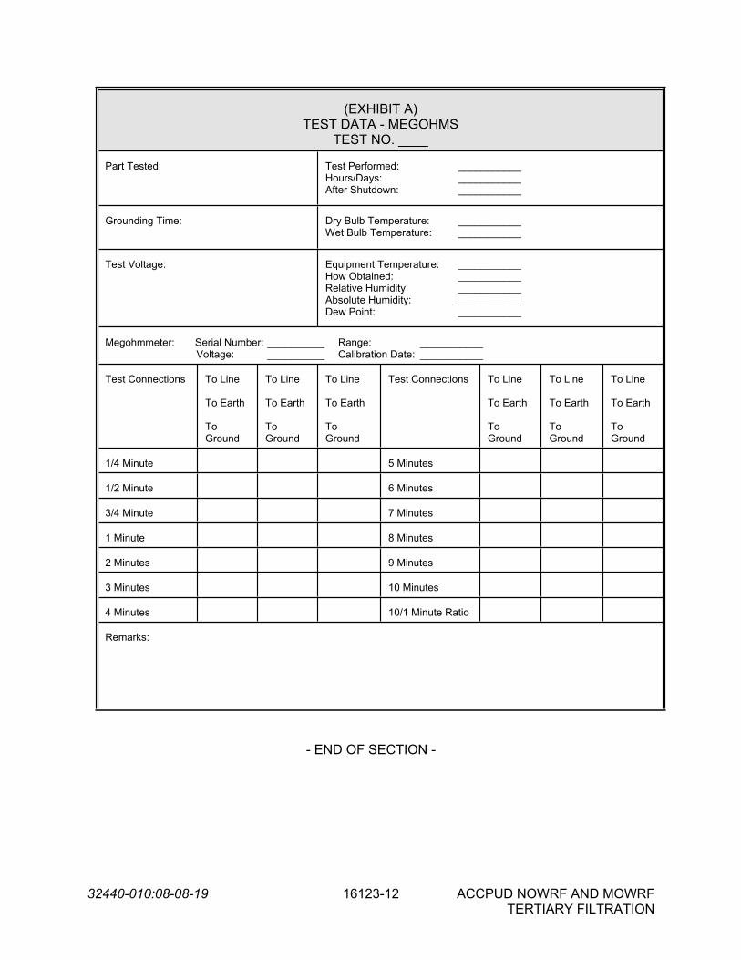
32440-010:08-08-19 16123-12 ACCPUD NOWRF AND MOWRFTERTIARY FILTRATION
(EXHIBIT A)TEST DATA - MEGOHMS
TEST NO. ____
Part Tested: Test Performed: ___________Hours/Days: ___________After Shutdown: ___________
Grounding Time: Dry Bulb Temperature: ___________Wet Bulb Temperature: ___________
Test Voltage: Equipment Temperature: ___________How Obtained: ___________Relative Humidity: ___________Absolute Humidity: ___________Dew Point: ___________
Megohmmeter: Serial Number: __________ Range: ___________Voltage: __________ Calibration Date: ___________
Test Connections To Line
To Earth
To Ground
To Line
To Earth
To Ground
To Line
To Earth
To Ground
Test Connections To Line
To Earth
To Ground
To Line
To Earth
To Ground
To Line
To Earth
To Ground
1/4 Minute 5 Minutes
1/2 Minute 6 Minutes
3/4 Minute 7 Minutes
1 Minute 8 Minutes
2 Minutes 9 Minutes
3 Minutes 10 Minutes
4 Minutes 10/1 Minute Ratio
Remarks:
- END OF SECTION -
32440-010:08-08-19 16130-1 ACCPUD NOWRF AND MOWRFTERTIARY FILTRATION
SECTION 16130
BOXES
PART 1 -- GENERAL
1.01 THE REQUIREMENT
A. The scope of work under this Section includes furnishing and installing all pull boxes, junction boxes, and outlet boxes.
B. Requirements for other boxes and enclosures are not included in this Section. Reference each specific Division 16 equipment Section for requirements related to that equipment’s respective enclosure.
C. Reference Section 16000, Basic Electrical Requirements, and Section 16111, Conduit.
1.02 CODES AND STANDARDS
A. Boxes shall be designed, manufactured, and/or listed to the following standards as applicable:
1. UL 514A - Metallic Outlet Boxes
2. UL 514C - Standard for Non-metallic Outlet Boxes, Flush Device Boxes, and Covers
3. UL 50 – Enclosures for Electrical Equipment, Non-environmental Considerations
4. UL 50E - Enclosures for Electrical Equipment, Environmental Considerations
5. UL 1203 – Standard for Explosion-proof and Dust-ignition-proof Electrical Equipment for use in Hazardous (Classified) Locations.
6. NEMA 250 – Enclosures for Electrical Equipment
1.03 SUBMITTALS
A. In accordance with the procedures and requirements set forth in the General Conditions and Section 01300, Submittals, the Contractor shall obtain from the equipment manufacturer(s) and submit the following:
1. Shop Drawings
B. Each submittal shall be identified by the applicable specification section.
020618DA7BR

32440-010:08-08-19 16130-2 ACCPUD NOWRF AND MOWRFTERTIARY FILTRATION
1.04 SHOP DRAWINGS
A. Each submittal shall be complete in all respects, incorporating all information and data listed herein and all additional information required for evaluation of the proposed equipment's compliance with the Contract Documents.
B. Partial, incomplete or illegible Submittals will be returned to the Contractor without review for resubmittal.
C. Shop drawings shall include but not be limited to:
1. Product data sheets for boxes, terminal strips, and all accessories
1.05 OPERATION AND MAINTENANCE MANUALS
A. The Contractor shall submit operation and maintenance manuals in accordance with the procedures and requirements set forth in the General Conditions and Division 1.
B. As-built drawings showing dimensions, internal box layout, terminal strip information, and terminal strip identification information shall be provided for all junction boxes. As-built drawings are not required for pull boxes or outlet boxes.
1.06 IDENTIFICATION
A. Each pull and junction box shall be identified with the box name as indicated on the Contract Drawings (e.g. PPB-FIL-1, CJB-FIL-1) or as directed by the Engineer. A nameplate shall be securely affixed in a conspicuous place on each box. Nameplates shall be as specified in Section 16195, Electrical – Identification.
PART 2 -- PRODUCTS
2.01 MANUFACTURERS
A. The equipment covered by this Specification is intended to be standard equipment of proven performance as manufactured by reputable concerns. Equipment shall be designed, constructed, and installed in accordance with the best practices of the trade, and shall operate satisfactorily when installed as shown on the Drawings.
2.02 PULL AND JUNCTION BOXES
A. General
1. All pull and junction boxes shall be UL listed and labeled.
2. Pull and junction boxes shall not be provided with eccentric or concentric knockouts.
3. Pull and junction boxes mounted embedded in concrete shall be UL listed for embedment.

32440-010:08-08-19 16130-3 ACCPUD NOWRF AND MOWRFTERTIARY FILTRATION
4. Where metallic boxes are used they shall be of all welded construction. Tack welded boxes are not acceptable.
B. Pull Boxes
1. All pull boxes shall be provided with a matching gasketed cover. For covers with dimensions of 24 inches by 24 inches or less, the cover shall be held in place by machine screws. Other screw types are not acceptable. For covers with dimensions greater than 24 inches by 24 inches, the cover shall be hinged and held in place by screw-operated clamp mechanisms. Hinge pins shall be removable. Clamp mechanism material of construction shall match that of the associated box.
2. Pull boxes shall not have any wire terminations inside, other than those for grounding/bonding. A ground bar shall be provided with the necessary number of screw type terminals. Twenty (20) percent of the total amount of terminals otherwise required for the pull box (minimum of two) shall be provided as spare terminations. Boxes requiring any other wire terminations shall be furnished and installed in accordance with the requirements for junction boxes herein.
3. Pull boxes shall be 6 inches wide by 6 inches tall by 4 inches deep, minimum. For applications requiring larger boxes, the box shall be sized in accordance with the fill requirements and dimensional requirements of the NEC.
4. Barriers shall be provided in pull boxes to isolate conductors of different voltages, types, and functions. Barrier material of construction shall match that of the box. Isolation shall be provided between the following groups:
a. Power wiring
b. AC control wiring
c. DC control wiring
d. Instrumentation wiring
C. Junction Boxes
1. Junction boxes used for lighting and receptacle circuits only shall be provided with a matching gasketed cover held in place by machine screws. Other screw types are not acceptable.
2. Junction boxes for all uses other than lighting and receptacle circuits shall be provided with a hinged, gasketed cover. Hinge pins shall be removable. Cover shall be held in place by screw-operated clamp mechanisms. Clamp mechanism material of construction shall match that of the associated box.
3. Barriers shall be provided in junction boxes to isolate conductors and terminal blocks of different voltages, types, and functions. Barrier material of construction shall match that of the box. Isolation shall be provided between the following groups:

32440-010:08-08-19 16130-4 ACCPUD NOWRF AND MOWRFTERTIARY FILTRATION
a. Power wiring
b. AC control wiring
c. DC control wiring
d. Instrumentation wiring
4. Junction boxes used for lighting and receptacle circuits only shall be allowed to have screw-on (wire nut) type connectors for wire terminations/junctions.
5. Junction boxes for all uses other than lighting and receptacle circuits shall be provided with terminal strips, consisting the necessary number of screw type terminals. Current carrying parts of the terminal blocks shall be of ample capacity to carry the full load current of the circuits connected, with a 10A minimum capacity. Terminal strips shall be rated for the voltage of the circuits connected. A separate ground bar shall be provided with the necessary number of screw type terminals. Twenty (20) percent of the total amount of terminals otherwise required for the junction box (minimum of two) shall be provided as spare terminations. When barriers are provided within the box, separate terminal strips shall be provided in each barrier area. Terminals shall be lettered and/or numbered to conform to the wiring labeling scheme in place on the project.
6. Junction boxes shall be 6 inches wide by 6 inches tall by 4 inches deep, minimum. For applications requiring larger boxes, the box shall be sized in accordance with the fill requirements and dimensional requirements of the NEC. Terminal blocks (including spare terminals) shall be considered when sizing the junction box.
D. Enclosure Types and Materials
1. In non-hazardous locations, pull and junction boxes shall be furnished with the following enclosure type and material of construction, dependent upon the designation of the area in which they are to be installed. Area designations are indicated on the Drawings.
AREA DESIGNATION ENCLOSURE TYPE AND MATERIAL
Indoor Wet Process Area NEMA 4X, Type 316 Stainless SteelIndoor Dry Process Area NEMA 12, Painted SteelIndoor Dry Non-process Area NEMA 1, Painted SteelIndoor Type 1 Chemical Storage/Transfer Area NEMA 4X, Fiberglass or PVCIndoor Type 2 Chemical Storage/Transfer Area NEMA 4X, Type 316 Stainless SteelAll Outdoor Areas NEMA 4X, Type 316 Stainless Steel

32440-010:08-08-19 16130-5 ACCPUD NOWRF AND MOWRFTERTIARY FILTRATION
2. In hazardous locations, pull and junction boxes shall be furnished with the following enclosure type and material of construction, dependent upon the classification of the area in which they are to be installed. Area classifications are indicated on the Drawings.
AREA CLASSIFICATION ENCLOSURE TYPE AND MATERIALClass 1, Division 1, Group D NEMA 7, Die Cast AluminumClass 1, Division 2, Group D NEMA 4X, Type 304 Stainless SteelClass 2, Division 1, Group F NEMA 9, Die Cast AluminumClass 2, Division 2, Group F NEMA 4X, Type 304 Stainless Steel
3. Non-metallic enclosures, NEMA 7 enclosures, and NEMA 9 enclosures shall be provided with threaded integral conduit hubs.
2.03 OUTLET BOXES
A. General
1. Outlet boxes shall be provided with a trim appropriate for the wiring device installed inside. Reference Section 16141, Wiring Devices, for outlet box trim requirements. An appropriate outlet box trim is required to achieve the NEMA rating of the outlet boxes as specified herein.
B. Surface Mount Outlet Boxes
1. Outlet boxes shall be the deep type, no less than 2.5 inches deep.
2. Outlet boxes shall be provided in single or multi-gang configuration as required, sized in accordance with the requirements of the NEC.
3. In non-hazardous locations, outlet boxes shall be furnished with the following enclosure type and material of construction, dependent upon the designation of the area in which they are to be installed. Area designations are indicated on the Drawings.
AREA DESIGNATION ENCLOSURE TYPE AND MATERIALIndoor Wet Process Area NEMA 4X, Cast Aluminum [PVC Coated
Steel]Indoor Dry Process Area NEMA 1, Cast AluminumIndoor Dry Non-process Area NEMA 1, Cast AluminumIndoor Type 1 Chemical Storage/Transfer Area NEMA 4X, PVC
Indoor Type 2 Chemical Storage/Transfer Area
NEMA 4X, Cast Aluminum[PVC Coated Steel]
All Outdoor Areas NEMA 4X, Cast Aluminum[PVC Coated Steel]
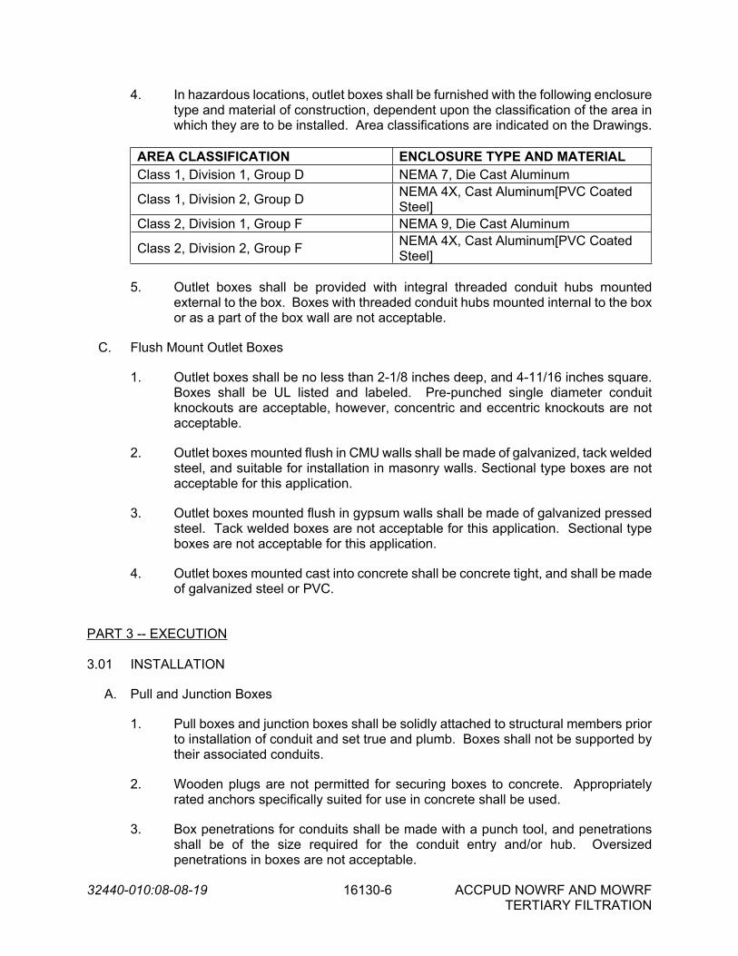
32440-010:08-08-19 16130-6 ACCPUD NOWRF AND MOWRFTERTIARY FILTRATION
4. In hazardous locations, outlet boxes shall be furnished with the following enclosure type and material of construction, dependent upon the classification of the area in which they are to be installed. Area classifications are indicated on the Drawings.
AREA CLASSIFICATION ENCLOSURE TYPE AND MATERIALClass 1, Division 1, Group D NEMA 7, Die Cast Aluminum
Class 1, Division 2, Group D NEMA 4X, Cast Aluminum[PVC Coated Steel]
Class 2, Division 1, Group F NEMA 9, Die Cast Aluminum
Class 2, Division 2, Group F NEMA 4X, Cast Aluminum[PVC Coated Steel]
5. Outlet boxes shall be provided with integral threaded conduit hubs mounted external to the box. Boxes with threaded conduit hubs mounted internal to the box or as a part of the box wall are not acceptable.
C. Flush Mount Outlet Boxes
1. Outlet boxes shall be no less than 2-1/8 inches deep, and 4-11/16 inches square. Boxes shall be UL listed and labeled. Pre-punched single diameter conduit knockouts are acceptable, however, concentric and eccentric knockouts are not acceptable.
2. Outlet boxes mounted flush in CMU walls shall be made of galvanized, tack welded steel, and suitable for installation in masonry walls. Sectional type boxes are not acceptable for this application.
3. Outlet boxes mounted flush in gypsum walls shall be made of galvanized pressed steel. Tack welded boxes are not acceptable for this application. Sectional type boxes are not acceptable for this application.
4. Outlet boxes mounted cast into concrete shall be concrete tight, and shall be made of galvanized steel or PVC.
PART 3 -- EXECUTION
3.01 INSTALLATION
A. Pull and Junction Boxes
1. Pull boxes and junction boxes shall be solidly attached to structural members prior to installation of conduit and set true and plumb. Boxes shall not be supported by their associated conduits.
2. Wooden plugs are not permitted for securing boxes to concrete. Appropriately rated anchors specifically suited for use in concrete shall be used.
3. Box penetrations for conduits shall be made with a punch tool, and penetrations shall be of the size required for the conduit entry and/or hub. Oversized penetrations in boxes are not acceptable.

32440-010:08-08-19 16130-7 ACCPUD NOWRF AND MOWRFTERTIARY FILTRATION
4. Watertight conduit hubs shall be provided for boxes where a NEMA 4X enclosure rating is specified. Reference Section 16111, Conduit, for conduit hub requirements.
5. Pull and junction boxes may be installed flush mounted in gypsum, concrete or CMU walls where appropriate provided that covers are easily removed or opened.
6. Pull and junction boxes shall be provided in the enclosure type and material of construction required for the area in which it is installed. Reference the requirements in Part 2 herein, and the area designations indicated on the Drawings.
B. Outlet Boxes
1. Outlet boxes shall be solidly attached to structural members prior to installation of conduit and set true and plumb. Boxes shall not be supported by their associated conduits.
2. Wooden plugs are not permitted for securing boxes to concrete. Appropriately rated anchors specifically suited for use in concrete shall be used.
3. Flush mounted outlet boxes shall be arranged and located so that tile and grout lines fit closely around the boxes, and so placed that the cover or device plate shall fit flush to the finished wall surface.
4. Outlet boxes shall be flush mounted in finished areas and other areas where practical. Flush mounted outlet boxes shall not be installed in hazardous areas and type 1 or 2 chemical storage/transfer areas.
5. For the below-named items, mounting heights from finished floor, or finished grade to top is applicable, depending on the type of wiring device to be installed in the outlet box. Mounting heights for outlet boxes shall be as follows, unless otherwise specified herein, indicated on the Drawings, or required by the Americans with Disability Act (ADA):
a. Light switches, 48 inchesb. Receptacles in indoor dry process/non-process areas, 16 inchesc. Receptacles in indoor wet process areas and all indoor chemical
storage/transfer areas, 48 inchesd. Receptacles in outdoor locations, 24 inches
6. Outlet boxes shall be provided in the material of construction required for the area in which it is installed. Reference the requirements in Part 2 herein, and the area designations indicated on the Drawings.
- END OF SECTION -

32440-010:08-08-19 16130-8 ACCPUD NOWRF AND MOWRFTERTIARY FILTRATION
THIS PAGE
INTENTIONALLY
LEFT BLANK

32440-010:08-08-19 16170-1 ACCPUD NOWRF AND MOWRFTERTIARY FILTRATION
SECTION 16170
GROUNDING AND BONDING
PART 1 -- GENERAL
1.01 THE REQUIREMENT
A. The Contractor shall furnish and install grounding systems complete in accordance with the minimum requirements established by Article 250 of the NEC. Article 250 of the NEC shall be considered a minimum requirement for compliance with this Specification.
B. Grounding of all instrumentation and control systems shall be furnished and installed in accordance with the manufacturer/system requirements and IEEE 1100. Conflicts shall be promptly brought to the attention of the Engineer.
C. In addition to the NEC requirements, building structural steel columns shall be permanently and effectively grounded:
D. Reference Section 16000, Basic Electrical Requirements
1.02 CODES AND STANDARDS
A. Equipment and materials covered under this Section shall be designed, manufactured, and/or listed to the following standards as applicable:
1. UL 467 – Grounding and Bonding Equipment
2. IEEE 81 – Guide for Measuring Earth Resistivity, Ground Impedance, and Earth Surface Potentials of a Ground System.
3. IEEE 1100 – Recommended Practice for Power and Grounding Electronic Equipment
1.03 SUBMITTALS
A. In accordance with the procedures and requirements set forth in the General Conditions and Section 01300, Submittals, the Contractor shall obtain from the equipment manufacturer and submit the following:
1. Shop Drawings
2. Reports of certified field tests.
B. Each submittal shall be identified by the applicable specification section.
1.04 SHOP DRAWINGS
061417BR

32440-010:08-08-19 16170-2 ACCPUD NOWRF AND MOWRFTERTIARY FILTRATION
A. Each submittal shall be complete in all respects, incorporating all information and data listed herein and all additional information required for evaluation of the proposed equipment's compliance with the Contract Documents.
B. Partial, incomplete, or illegible submittals will be returned to the Contractor without review for resubmittal.
C. Shop drawings shall include but not be limited to:
1. Product data sheets.
2. Drawings and written description of how the Contractor intends to furnish and install the grounding system.
PART 2 -- PRODUCTS
2.01 MANUFACTURERS
A. The equipment covered by these specifications shall be standard equipment of proven performance as manufactured by reputable concerns. Equipment shall be designed, constructed, and installed in accordance with the best practices of the trade, and shall operate satisfactorily when installed as shown on the Drawings.
2.02 GROUND RODS AND GRID
A. Ground rods shall be rolled to a commercially round shape from a welded copper-clad steel manufactured by the molten-welding process or by the electro-formed process (molecularly bonded). They shall have an ultimate tensile strength of 75,000 pounds per square inch (psi) and an elastic limit of 49,000 psi. The rods shall be not less than 3/4 inch in diameter by 10 feet in length; and the proportion of copper shall be uniform throughout the length of the rod. The copper shall have a minimum wall thickness of 0.010 inch at any point on the rod. Ground rods shall be UL 467 listed. The ground rods shall be manufactured by Erico Products, Blackburn, or equal.
B. Except where specifically indicated otherwise, all exposed non current-carrying metallic parts of electrical equipment, metallic raceway systems, grounding conductors in nonmetallic raceways and neutral conductors of wiring systems shall be grounded.
C. The ground connection shall be made at the main service equipment and shall be extended to the ground grid surrounding the structure. The ground grid shall also be connected to the point of entrance of the metallic water service. Connection to the water pipe shall be made by a suitable ground clamp or lug connection to a plugged tee. If flanged pipes are encountered, connection shall be made with the lug bolted to the street side of the flanged connection.
D. Where ground fault protection is employed, care shall be taken so that the connection of the ground and neutral does not interfere with the correct operation of the ground fault protection system.
2.03 FITTINGS

32440-010:08-08-19 16170-3 ACCPUD NOWRF AND MOWRFTERTIARY FILTRATION
A. Grounding connections to equipment shall be bolted. Cable end connections shall be made by hydraulic crimp or exothermically welded. Split bolt type connectors are not acceptable. Fittings shall be UL 467 listed.
2.04 EQUIPMENT GROUNDING CONDUCTORS
A. An insulated equipment grounding conductor, which shall be separate from the electrical system neutral conductor, shall be furnished and installed for all circuits. Insulation shall be of the same type as the ungrounded conductors in the raceway and shall be green in color. Equipment grounding conductors shall be furnished and installed in all conduits. Use of conduits as the NEC required equipment grounding conductor is not acceptable.
2.05 EQUIPMENT GROUNDS
A. Equipment grounds shall be solid and continuous from a connection at earth to all distribution panelboards. Ground connections at panelboards, outlets, equipment, and apparatus shall be made in an approved and permanent manner.
B. For all control panels, disconnect switches, and other electrical enclosures, equipment grounds and bonding jumpers shall be terminated individually on a ground bar or mechanical lugs. No wire nuts will be permitted.
2.06 EXOTHERMIC WELDS
A. All exothermic welding shall be completed per welding kit manufacturer's instructions. Exothermic welds shall be CadWeld by Erico or ThermoWeld.
PART 3 -- EXECUTION
3.01 INSTALLATION
A. Metal surfaces where grounding connections are to be made shall be clean and dry. Steel surfaces shall be ground or filed to remove all scale, rust, grease, and dirt. Copper and galvanized steel shall be cleaned with emery cloth to remove oxide before making connections.
B. Ground Grid
1. A main ground grid shall be provided for each structure and interconnecting structure grids consisting of driven ground rods as shown on the Drawings. Ground rods shall be driven straight down into the earth, or if objects are encountered, at an angle to avoid the obstruction.
2. The ground rods shall be interconnected by the use of copper cable exothermically welded to the rods. The grounding cables shall be installed after the excavations for the building have been completed and prior to the pouring of concrete for the footings, mats, etc. Copper "pigtails" shall be connected to the ground grid and shall enter the buildings and structure from the outside and shall be connected to steel structures, and equipment as described in this Section and as required to provide a complete grounding system. The copper pigtails shall be exothermically

32440-010:08-08-19 16170-4 ACCPUD NOWRF AND MOWRFTERTIARY FILTRATION
welded to the ground grid, and connected to building reinforcement steel by hydraulic crimp.
3. Grounding conductors shall be continuous between points of connection; splices shall not be permitted.
4. Where conductors are exposed and subject to damage from personnel, traffic, etc., conductors shall be installed in metal raceway. The raceway shall be bonded to the grounding system.
5. Where subsurface conditions do not permit use of driven ground rods to obtain proper ground resistance, rods shall be installed in a trench or plate electrodes shall be provided, as applicable and necessary to obtain proper values of resistance.
6. Buried exothermic welds and ground ring shall not be backfilled until inspected by Engineer.
C. Raceways
1. Conduit which enters equipment such as switchgear, motor control centers, transformers, panelboards, variable frequency drives, instrument and control panels, and similar equipment shall be bonded to the ground bus or ground lug, where provided, and as otherwise required by the NEC.
3.02 TESTING
A. All tests shall be performed in accordance with the requirements of the General Conditions and Division 1. The following tests are required:
1. Witnessed Shop Tests
a. None required.2. Field Tests
a. Field testing shall be done in accordance with the requirements specified in the General Conditions, Division 1, and NETA Acceptance Testing Specifications, latest edition.
b. Fall of potential tests shall be performed on the ground grid per IEEE81 recommendations by a third party, independent testing firm. A fall of potential plot shall be submitted at the conclusion of testing for Engineer review. Documentation indicating the location of the rod and grounding system as well as the resistance and soil conditions at the time the measurements were made shall be submitted. Testing shall show that the ground grid has 5 ohms resistance or less. Due to soil conditions and/or unforeseen field conditions, ground resistances greater than 5 ohms may be acceptable if specifically approved in writing by the Engineer. Ground resistance measurements shall be made in normally dry weather not less than 48 hours after rainfall and with the ground grid under test isolated from other grounds.

32440-010:08-08-19 16170-5 ACCPUD NOWRF AND MOWRFTERTIARY FILTRATION
c. Continuity tests for the grounding electrode conductor shall be performed. Test will be accepted when a resistance of less than 1 ohm is shown for this conductor.
- END OF SECTION -

32440-010:08-08-19 16170-6 ACCPUD NOWRF AND MOWRFTERTIARY FILTRATION
THIS PAGE
INTENTIONALLY
LEFT BLANK

32440-010:08-08-19 16190-1 ACCPUD NOWRF AND MOWRFTERTIARY FILTRATION
SECTION 16190
SUPPORTING DEVICES
PART 1 -- GENERAL
1.01 THE REQUIREMENT
A. The Contractor shall furnish and install structural supports for mounting and installing all conduit, electrical equipment, lighting, alarm systems, instrumentation, and communications equipment furnished under this Contract.
B. Equipment shall be installed strictly in accordance with recommendations of the manufacturer and best practices of the trade resulting in a complete, operable, and safe installation. The Contractor shall obtain written installation manuals from the equipment manufacturer prior to installation.
C. Reference Section 16000, Basic Electrical Requirements.
1.02 CODES AND STANDARDS
A. Equipment and materials covered under this Section shall be designed, manufactured, and/or listed to the following standards as applicable:
1. ASTM A123 – Standard Specification for Zinc (Hot Dip Galvanized) Coatings on Iron and Steel Products.
2. ASTM A153 – Standard Specification for Zinc Coating (Hot Dip) on Iron and Steel Hardware.
3. ASTM A240 – Standard Specification for Chromium and Chromium-Nickel Stainless Steel Plate, Sheet, and Strip for Pressure Vessels and for General Applications.
4. ASTM A276 – Standard Specification for Steel Bars and Shapes
5. ASTM B783 – Standard Specification for Materials for Ferrous Powder Metallurgy Structural Parts
1.03 SUBMITTALS
A. In accordance with the procedures and requirements set forth in the General Conditions and Section 01300, Submittals, the Contractor shall obtain from the equipment manufacturer and submit the following:
1. Shop drawings
2. Structural support calculations (if required)
102218DABR

32440-010:08-08-19 16190-2 ACCPUD NOWRF AND MOWRFTERTIARY FILTRATION
B. Each submittal shall be identified by the applicable Specification section.
1.04 SHOP DRAWINGS
A. Each submittal shall be complete in all respects, incorporating all information and data listed herein and all additional information required for evaluation of the proposed equipment's compliance with the Contract Documents.
B. Partial, incomplete, or illegible submittals will be returned to the Contractor without review for resubmittal.
C. Shop drawings shall include but not be limited to:
1. Product data sheets.
2. Complete assembly, layout, installation, and foundation drawings with clearly marked dimensions.
PART 2 -- PRODUCTS
2.01 MANUFACTURERS
A. The equipment covered by this Specification is intended to be standard equipment of proven performance as manufactured by reputable concerns. Equipment shall be designed, constructed, and installed in accordance with the best practices of the trade, and shall operate satisfactorily when installed as shown on the Drawings.
2.02 MATERIALS
A. Support channel shall be 1-5/8” by 1-5/8” minimum, with 12 gage material thickness.
B. Support channel, support channel fittings, and threaded rod shall be furnished with the following material of construction, dependent upon the designation of the area in which they are to be installed. Area designations are indicated on the Drawings.
AREA DESIGNATION MATERIAL OF CONSTRUCTIONIndoor Wet Process Area Type 316 Stainless SteelIndoor Dry Process Area Hot Dipped Galvanized SteelIndoor Dry Non-process Area Hot Dipped Galvanized SteelIndoor Type 1 Chemical Storage/Transfer Area FiberglassIndoor Type 2 Chemical Storage/Transfer Area Type 316 Stainless SteelAll Outdoor Areas Type 316 Stainless SteelAll Hazardous Areas Type 316 Stainless Steel

32440-010:08-08-19 16190-3 ACCPUD NOWRF AND MOWRFTERTIARY FILTRATION
C. Fastening hardware (bolts, nuts, washers, and screws) shall be furnished with the following material of construction, dependent upon the designation of the area in which they are to be installed. Area designations are indicated on the Drawings.
AREA DESIGNATION MATERIAL OF CONSTRUCTIONIndoor Wet Process Area Type 316 Stainless SteelIndoor Dry Process Area Type 304 Stainless SteelIndoor Dry Non-process Area Type 304 Stainless SteelIndoor Type 1 Chemical Storage/Transfer Area FiberglassIndoor Type 2 Chemical Storage/Transfer Area Type 316 Stainless SteelAll Outdoor Areas Type 316 Stainless SteelAll Hazardous Areas Type 316 Stainless Steel
PART 3 -- EXECUTION
3.01 INSTALLATION
A. Concrete or Masonry Inserts
1. The Contractor shall be responsible for the furnishing and installation of all anchor bolts, masonry inserts, and similar devices required for installation of equipment furnished under this Contract.
2. If a time delay for the arrival of any special inserts or equipment drawings, etc. occurs, the Contractor may, if permitted by the Engineer, make arrangements for providing approved recesses and openings in the concrete or masonry and, upon subsequent installation, the Contractor shall be responsible for filling in such recesses and openings. Any additional costs that may be incurred by this procedure shall be borne by the Contractor.
3. The Contractor shall furnish leveling channels for all switchgear, switchboards, motor control centers, and similar floor mounted equipment. The leveling channels shall be provided for embedment in the equipment housekeeping pads. Coordination of the installation of these channels with the concrete pad is essential and required. Pad height shall be as required to maintain concrete coverage of the reinforcement bars while not causing associated equipment to exceed the maximum mounting height requirements of the NEC.
B. Support Fastening and Locations
1. All equipment fastenings to columns, steel beams, and trusses shall be by beam clamps or welded. No holes shall be drilled in the steel.
2. Unless otherwise indicated on the Drawings or in the Specifications, handrails/guardrails shall not be utilized as supports for electrical equipment, devices, or appurtenances. Handrails/guardrails shall not be cut, drilled, or otherwise modified in order to accommodate electrical supports without written approval from the Engineer.

32440-010:08-08-19 16190-4 ACCPUD NOWRF AND MOWRFTERTIARY FILTRATION
3. All holes made in reflected ceilings for support rods, conduits, and other equipment shall be made adjacent to ceiling grid bars where possible, to facilitate removal of ceiling panels.
4. Support channel shall be provided wherever required for the support of starters, switches, panels, and miscellaneous equipment.
5. All equipment, devices, and raceways that are installed on the dry side of a water bearing wall shall not be installed directly onto the wall. Support channel shall be used to allow ventilation air to pass behind the equipment, devices, or raceway.
6. All supports shall be rigidly bolted together and braced to make a substantial supporting framework. Where possible, control equipment shall be grouped together and mounted on a single framework.
7. Aluminum support members shall not be installed in direct contact with concrete. Stainless steel or non-metallic "spacers" shall be used to prevent contact of aluminum with concrete.
8. Actual designs for supporting framework should take the nature of a picture frame of support channels and bracket with a plate for mounting the components. The Contractor is responsible for the design of supporting structure; Contractor shall submit design details to the Engineer for acceptance before proceeding with the fabrication.
9. Wherever dissimilar metals come into contact, the Contractor shall isolate these metals as required with neoprene washers, nine (9) mil polyethylene tape, or gaskets.
10. For all installations where fiberglass supporting materials are required, the Contractor shall submit structural calculations and the details of the proposed system of support. Structural calculations shall be signed and sealed by a registered professional engineer in the state in which the project is located.
11. For the following installations where conduits are provided with a support system suspended from the above or attached to a vertical structure, the Contractor shall submit structural calculations and details of the proposed system of support. Structural calculations shall be signed and sealed by a registered professional engineer in the state in which the project is located.
a. A quantity of twelve (12) or more conduits trade size 1” and smaller are proposed for a conduit support rack.
b. A quantity of eight (8) or more conduits trade sizes 1 ½” to 2 1/2” are proposed for a conduit support rack.
c. A quantity of four (4) or more conduits trade sizes 3” and larger are proposed for a conduit support rack.
12. Single conduits installed exposed along walls and ceilings shall be secured to the wall or ceiling with a one-hole conduit clamp and clamp-back. Where multiple

32440-010:08-08-19 16190-5 ACCPUD NOWRF AND MOWRFTERTIARY FILTRATION
conduits are installed exposed together, support channel and conduit clamps shall be used.
C. Equipment, boxes, and enclosures which are factory-constructed with integral mounting provisions (such as brackets, mounting feet, bolt holes, etc.) shall be installed/supported utilizing those mounting provisions. Equipment, boxes and enclosures shall not be field modified to enable mounting by any other means. Equipment, boxes, and enclosures that are field-modified by any means which compromises the UL Listing or NEMA rating of the enclosure/assembly shall be removed and replaced by the Contractor at no additional cost to the Owner
- END OF SECTION -

32440-010:08-08-19 16190-6 ACCPUD NOWRF AND MOWRFTERTIARY FILTRATION
THIS PAGE
INTENTIONALLY
LEFT BLANK

32440-010:08-08-19 16195-1 ACCPUD NOWRF AND MOWRFTERTIARY FILTRATION
SECTION 16195
ELECTRICAL - IDENTIFICATION
PART 1 -- GENERAL
1.01 THE REQUIREMENT
A. All electrical equipment shall be properly identified in accordance with these Specifications and the Contract Drawings. All switchgear, switchboards, motor control centers, variable frequency drives, lighting and distribution panelboards, combination starters, control panels, pull and junction boxes, enclosures, disconnect switches, control stations, and similar equipment shall be identified in the manner described, or in an equally approved manner.
B. The types of electrical identification specified in this section include, but are not limited to, the following:
1. Operational instructions and warnings.
2. Danger signs.
3. Equipment/system identification signs.
4. Nameplates.
1.02 SIGNS
A. "DANGER-HIGH-VOLTAGE" signs shall be securely mounted on the entry doors of all electrical rooms.
1.03 LETTERING AND GRAPHICS
A. The Contractor shall coordinate names, abbreviations, and other designations used in the electrical identification work with the corresponding designations shown, specified or scheduled. Provide numbers, lettering, and wording as indicated or, if not otherwise indicated, as recommended by manufacturers or as required for proper identification and operation/maintenance of the electrical systems and equipment.
1.04 SUBMITTALS
A. In accordance with the procedures and requirements set forth in the General Conditions and Section 01300, Submittals, the Contractor shall obtain from the equipment manufacturer and submit shop drawings. Each submittal shall be identified by the applicable specification section.
0317175BR

32440-010:08-08-19 16195-2 ACCPUD NOWRF AND MOWRFTERTIARY FILTRATION
1.05 SHOP DRAWINGS
A. Each submittal shall be complete in all respects, incorporating all information and data listed herein and all additional information required for evaluation of the proposed equipment's compliance with the Contract Documents.
B. Partial, incomplete, or illegible submittals will be returned to the Contractor without review for resubmittal.
C. Shop drawings shall include but not be limited to:
1. Product data sheets.
PART 2 -- PRODUCTS
2.01 MANUFACTURERS
A. The material covered by these Specifications is intended to be standard material of proven performance as manufactured by reputable concerns. Material shall be fabricated, constructed, and installed in accordance with the best practices of the trade, and shall operate satisfactorily when installed as specified herein and shown on the Drawings.
2.02 NAMEPLATES
A. Nameplates shall be engraved, high pressure plastic laminate, white with black lettering.
B. Nameplates shall be attached to NEMA 4X enclosures utilizing UL-recognized mounting kits designed to maintain the overall UL Type rating of the enclosure. Mounting kit fasteners shall be stainless steel Type AHK10324X as manufactured by Hoffman, or equal.
2.03 HIGH VOLTAGE SIGNS
A. Standard "DANGER" signs shall be of baked enamel finish on 20 gage steel; of standard red, black and white graphics; 14 inches by 10 inches size except where 10 inches by 7 inches is the largest size which can be applied where needed, and except where a larger size is needed for adequate identification.
2.04 CONDUIT IDENTIFICATION
A. Conduit identification shall be as specified in Section 16111, Conduit.
2.05 WIRE AND CABLE IDENTIFICATION
A. Field installed wire and cable identification shall be as specified in Section 16123, and Low Voltage Wire and Cable.
B. A plastic laminate nameplate shall be provided at each panelboard, motor control center, switchgear assembly, and switchboard assembly. This nameplate shall be used to clearly

32440-010:08-08-19 16195-3 ACCPUD NOWRF AND MOWRFTERTIARY FILTRATION
convey the conductor identification means used at that piece of equipment (i.e. Phase A=Brown, Phase B=Orange, C = Yellow).
C. Wiring identification for factory installed wiring in equipment enclosures shall be as specified in the respective section.
2.06 BOX IDENTIFICATION
A. Pull, junction and device box identification shall be as specified in Section 16130 – Boxes.
PART 3 -- EXECUTION
3.01 NAMEPLATES
A. Nameplates shall be attached to the equipment enclosures with (2) two stainless steel sheet metal screws for nameplates up to 2-inches wide. For nameplates over 2-inches wide, four (4) stainless steel sheet metal screws shall be used, one (1) in each corner of the nameplate. The utilization of adhesives is not permitted.
3.02 OPERATIONAL IDENTIFICATION AND WARNINGS
A. Wherever reasonably required to ensure safe and efficient operation and maintenance of the electrical systems and electrically connected mechanical systems and general systems and equipment, including prevention of misuse of electrical facilities by unauthorized personnel, install plastic signs or similar equivalent identification, instruction, or warnings on switches, outlets, and other controls, devices, and covers or electrical enclosures. Where detailed instructions or explanations are needed, provide plasticized tags with clearly written messages adequate for the intended purposes. Signs shall be attached as specified above for nameplates.
3.03 POWER SOURCE IDENTIFICATION
A. After installation of all field equipment (i.e. valves, motors, fans, unit heaters, instruments, etc) install nameplates at each power termination for the field equipment. Nameplate data shall include equipment designation (tag number), power source (MCC number, panelboard, etc), circuit number, conduit number from schedule and voltage/phase.
B. Contractor to coordinate with the Engineer and the Owner regarding exact nameplate placement during construction.
C. Nameplates shall be as specified herein.
- END OF SECTION -

32440-010:08-08-19 16195-4 ACCPUD NOWRF AND MOWRFTERTIARY FILTRATION
THIS PAGE
INTENTIONALLY
LEFT BLANK

32440-010:08-08-19 16280-1 ACCPUD NOWRF AND MOWRFTERTIARY FILTRATION
SECTION 16280
SURGE PROTECTIVE DEVICES
PART 1 - GENERAL
1.01 THE REQUIREMENT
A. The Contractor shall furnish, install, and place in satisfactory operation, the surge protective devices (SPD) as specified herein and indicated on the Drawings.
B. The surge protective devices specified under this Section shall be provided as a stand-alone unit, separate from the enclosure of the equipment to which they are connected. The requirements of this Section shall not apply to equipment where an integral SPD is specified.
C. Reference Section 16123, Low Voltage Wire and Cable, and Section 16195, Electrical Identification.
1.02 CODES AND STANDARDS
A. The surge protective device shall be designed, manufactured, and/or listed to the following standards as applicable:
1. Underwriters Laboratories, Inc. (UL)
a. UL1449, latest edition: Surge Protective Devices
b. UL1283, latest edition: Electromagnetic Interference Filters
B. American National Standards Institute (ANSI)/Institute of Electrical & Electronic Engineers (IEEE)
1. C62.41.1: 2002 Guide for Surge Voltages in Low-Voltage AC Power Circuits
2. C62.41.2: 2002 Recommend Practice on Characterization of Surges in Low Voltage (100V and Less) AC Power Circuits.
3. C62.45: 2002 IEEE Recommended Practice on Surge Testing for Equipment Connected to Low-Voltage (1000V and Less) AC Power Circuits
4. C62.62: 2000 IEEE Standard Test Specifications for Surge Protective Devices for Low Voltage (1000V and Less) AC Power Circuits
1.03 SUBMITTALS
A. In accordance with the procedures and requirements set forth in General Conditions and Section 01300, Submittals, the Contractor shall obtain from the equipment manufacturer and submit the following:
020618BR

32440-010:08-08-19 16280-2 ACCPUD NOWRF AND MOWRFTERTIARY FILTRATION
1. Shop Drawings
2. Operation and Maintenance Manuals
3. Spare Parts List
1.04 SHOP DRAWINGS
A. Each submittal shall be complete in all respects, incorporating all information and data listed herein and all additional information required for evaluation of the proposed equipment's compliance with the Contract Documents.
B. Partial, incomplete, or illegible submittals will be returned to the Contractor without review for re-submittal.
C. Drawings submitted by the manufacturer shall be complete and documented to provide the Owner with operations and maintenance capabilities.
D. Shop drawings for each SPD shall include but not be limited to:
1. A Compliance, Deviations, and Exceptions (CD&E) letter. If the shop drawings are submitted without this CD&E letter, the submittal will be rejected. The letter shall include all comments, deviations and exceptions taken to the Drawings and Specifications by the Contractor AND Equipment Manufacturer/Supplier. This letter shall include a copy of this specification section. In the left margin beside each and every paragraph/item, a letter "C", "D", or "E" shall be typed or written in. The letter "C" shall be for full compliance with the requirement. The letter "D" shall be for a deviation from the requirement. The letter "E" shall be for taking exception to a requirement. Any requirements with the letter "D" or "E" beside them shall be provided with a full typewritten explanation of the deviation/exception. Handwritten explanation of the deviations/exceptions is not acceptable. The CD&E letter shall also address deviations, and exceptions taken to each Drawing related to this Specification Section.
2. Product Data Sheets.
3. Detailed drawings showing weights and dimensions.
4. Wiring diagrams showing field connections.
5. Proof that all products provided under this Section are UL listed and labeled by Underwriters Laboratories to UL1449, latest Edition. This proof shall be a copy of the data listed under the UL File Number for the manufacturer, which may be obtained from the UL Online Certification Directory. No other means of proving compliance (such as manufacturer data sheets, marketing material, etc) will be considered acceptable.
6. Proof of Short Circuit Current Ratings (SCCR), Voltage Protection Ratings (VPRs) for all modes, Maximum Continuous Operating Voltage rating (MCOV), Nominal
32440-010:08-08-19 16280-3 ACCPUD NOWRF AND MOWRFTERTIARY FILTRATION
Discharge Current (In), and device listing Type shall be submitted using the same means as described in the paragraph above.
7. Proof that all products provided under this Section are UL listed and labeled by Underwriters Laboratories to UL 1283, latest Edition. This proof shall be a copy of the data listed under the UL File Number for the manufacturer, which may be obtained from the UL Online Certification Directory. No other means of proving compliance (such as manufacturer data sheets, marketing material, etc) will be considered acceptable.
8. Warranty Information
E. The shop drawing information shall be complete and organized in such a way that the Engineer can determine if the requirements of these Specifications are being met. Copies of technical bulletins, technical data sheets from "Soft Cover" catalogs, and similar information which is "highlighted" or somehow identifies the specific equipment items the Contractor intends to provide are to provide are acceptable and shall be submitted.
1.05 OPERATION AND MAINTENANCE MANUALS
A. The Contractor shall submit operation and maintenance manuals in accordance with the procedures and requirements set forth in the General Conditions and Division 1.
1.06 SPARE PARTS
A. All spare parts as recommended by the equipment manufacturer shall be furnished by the Contractor to the Owner.
B. The Contractor shall furnish one (1) spare field replacement module of each rating provided under this Contract.
C. The spare parts shall be packed in containers suitable for long term storage, bearing labels clearly designating the contents and the pieces of equipment for which they are intended.
D. Spare parts shall be delivered at the same time as the equipment to which they pertain. The Contractor shall properly store and safeguard such spare parts until completion of the Work, at which time they shall be delivered to the Owner.
E. Spare parts lists, included with the shop drawing submittal shall indicate specific sizes, quantities, and part numbers of the items to be furnished. Terms such as "1 lot of packing material" are not acceptable.
F. Parts shall be completely identified with a numerical system to facilitate parts inventory control and stocking. Each part shall be properly identified by a separate number. Those parts which are identical for more than one size, shall have the same part number.
1.07 IDENTIFICATION
A. Each SPD shall be identified by the circuit number and equipment name as indicated on the Drawings. A nameplate shall be securely affixed in a conspicuous place on each SPD. Nameplates shall be as specified in Section 16195, Electrical - Identification.

32440-010:08-08-19 16280-4 ACCPUD NOWRF AND MOWRFTERTIARY FILTRATION
1.08 WARRANTY
A. All SPDs, associated hardware, and supporting components shall be warranted to be free from defects in materials and workmanship, under normal use and in accordance with the instructions provided, for a period of five (5) years after acceptance of the equipment by the Owner.
B. Any component or subassembly contained within the surge protection system that shows evidence of failure or incorrect operation during the five (5) year warranty period, shall be replaced by the manufacturer at no additional cost to the Owner.
PART 2 - PRODUCTS
2.01 GENERAL
A. The SPD units shall be UL 1449 Listed and must bear the UL mark. Units that are “manufactured in accordance with” UL 1449 or tested by other testing agencies “in accordance with” UL 1449 are not acceptable and will be rejected.
B. Type II SPD units shall be UL 1283 Listed and must bear the UL mark. Units that are “manufactured in accordance with” UL 1283 or tested by other testing agencies “in accordance with” UL 1283 are not acceptable and will be rejected. Further, SPD units using UL 1283 capacitors but not tested to UL 1283 will be rejected.
C. SPDs shall be provided as a stand-alone unit, separate from the equipment to which they are connected.
D. All SPDs furnished and installed under this Contract shall be from the same manufacturer.
2.02 PRODUCTS
A. Type I surge protective devices (SPD) shall be furnished and installed when shown without upstream overcurrent protection on the Drawings. Type II SPDs shall be provided in all other locations. Type II SPDs shall not require the use of a specific upstream overcurrent device. SPDs shall be provided in the location and quantity as shown on the Drawings.
B. Each SPD shall be rated for the voltage and configuration of the equipment to which it is connected.
C. Each Type II SPD shall have UL 1283 EMI/RFI filtering with minimum attenuation of -50dB at 100kHz.
D. The short circuit current rating of each SPD shall match or exceed the rating of the equipment to which it is connected. The Contractor shall reference the Drawings for short circuit current rating of each piece of equipment.
E. Each SPD system shall provide surge protection in all possible modes. Surge protection shall be as follows:
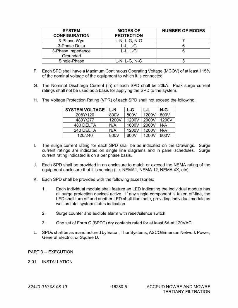
32440-010:08-08-19 16280-5 ACCPUD NOWRF AND MOWRFTERTIARY FILTRATION
SYSTEM CONFIGURATION
MODES OF PROTECTION
NUMBER OF MODES
3-Phase Wye L-N, L-G, N-G 73-Phase Delta L-L, L-G 6
3-Phase Impedance Grounded
L-L, L-G 6
Single-Phase L-N, L-G, N-G 3
F. Each SPD shall have a Maximum Continuous Operating Voltage (MCOV) of at least 115% of the nominal voltage of the equipment to which it is connected.
G. The Nominal Discharge Current (In) of each SPD shall be 20kA. Peak surge current ratings shall not be used as a basis for applying the SPD to the system.
H. The Voltage Protection Rating (VPR) of each SPD shall not exceed the following:
SYSTEM VOLTAGE L-N L-G L-L N-G208Y/120 800V 800V 1200V 800V480Y/277 1200V 1200V 2000V 1200V
480 DELTA N/A 1800V 2000V N/A240 DELTA N/A 1200V 1200V N/A
120/240 800V 800V 1200V 800V
I. The surge current rating for each SPD shall be as indicated on the Drawings. Surge current ratings are indicated on single line diagrams and in panel schedules. Surge current rating indicated is on a per phase basis.
J. Each SPD shall be provided in an enclosure to match or exceed the NEMA rating of the equipment enclosure that it is serving (i.e. NEMA1, NEMA 12, NEMA 4X, etc).
K. Each SPD shall be provided with the following accessories:
1. Each individual module shall feature an LED indicating the individual module has all surge protection devices active. If any single component is taken off-line, the LED shall turn off and another LED shall illuminate, providing individual module as well as total system status indication.
2. Surge counter and audible alarm with reset/silence switch.
3. One set of Form C (SPDT) dry contacts rated for at least 5A at 120VAC.
L. SPDs shall be as manufactured by Eaton, Thor Systems, ASCO/Emerson Network Power, General Electric, or Square D.
PART 3 -- EXECUTION
3.01 INSTALLATION

32440-010:08-08-19 16280-6 ACCPUD NOWRF AND MOWRFTERTIARY FILTRATION
A. The SPD units shall be furnished and installed as shown on the Drawings and in accordance with the manufacturer's installation instructions. One (1) copy of these instructions shall be included with the equipment at time of shipment.
B. The SPD units shall be mounted such that the conductor lengths are as short as possible, but no greater than 36 inches. Any installation resulting in a conductor length of greater than 36 inches shall be reviewed with the Engineer as a special type of cable may need to be installed. For equipment such as panelboards, the Contractor shall relocate the circuit breaker that is to be connected to the SPD as needed to achieve the shortest conductor length possible.
C. The Contractor shall use a close nipple to enclose the conductors between the SPD and the equipment served. However, if due to field conditions a 90 degree conduit bend is required to connect the SPD to the equipment that it serves, the bend shall have a minimum radius of 36 inches to eliminate any potential for sharp bends in the conductors.
D. Conductors between the equipment served and the SPD shall be 600V power wire and cable as specified in Section 16123 – Low Voltage Wire and Cable. The individual conductors shall be gently twisted, and shall be sized as indicated on the Drawings.
E. Prior to energizing, the Contractor shall verify that the SPD unit voltage and configuration is suitable for the system to which it is connected.
F. Prior to energizing, the Contractor shall also verify that any Neutral to Ground bonding jumpers are installed as required.
G. Prior to energizing, the Contractor shall also verify that the impedance of the equipment grounding conductor between the SPD and the grounding electrode system is less than 1 ohm.
3.02 TESTING
A. All tests shall be performed in accordance with the requirements of the General Conditions and Division 1. The following tests are required:
1. Shop Tests
a. Standard factory tests shall be performed on the equipment under this section. All tests shall be in accordance with the latest version of NEMA, ANSI, and UL standards.
b. All surge protective devices, subassemblies, and components shall be 100% tested and certified by the manufacturer to meet their published performance parameters.
2. Field Tests
a. None required.
- END OF SECTION -

32440-010:08-08-19 16902-1 ACCPUD NOWRF AND MOWRFTERTIARY FILTRATION
SECTION 16902
ELECTRIC CONTROLS AND RELAYS
PART 1 -- GENERAL
1.01 THE REQUIREMENT
A. The Contractor shall furnish, install, test, and place in satisfactory operation all electric controls and relays as specified herein and indicated on the Drawings.
B. Electrical control and relay systems shall be assembled using NEMA rated components. Components designed and built to International Electrotechnical Commission (IEC) standards are not recognized. Equipment designed, manufactured and labeled in compliance with IEC standards is not acceptable.
C. Reference Section 16000, Basic Electrical Requirements and Section 16195, Electrical Identification.
1.02 CODES AND STANDARDS
A. Products specified herein shall be in conformance with or listed to the following standards as applicable:
1. NEMA 250 – Enclosures for Electrical Equipment
2. UL 508A – Standard for Industrial Control Panels
3. UL-1203 – Standard for Explosion-proof and Dust-ignition-proof Electrical Equipment for use in Hazardous (Classified) Locations.
4. ANSI/ISA 12.12.01-2013 – Nonincendive Electrical Equipment for use in Class I and II, Division II Hazardous (Classified) locations.
1.03 SUBMITTALS
A. In accordance with the procedures and requirements set forth in the General Conditions and Section 01300, Submittals, the Contractor shall obtain from the equipment manufacturer and submit the following:
1. Shop Drawings
2. Spare Parts List
B. Each submittal shall be identified by the applicable specification section.
031717BR

32440-010:08-08-19 16902-2 ACCPUD NOWRF AND MOWRFTERTIARY FILTRATION
1.04 SHOP DRAWINGS
A. Each submittal shall be complete in all respects, incorporating all information and data listed herein and all additional information required for evaluation of the proposed equipment's compliance with the Contract Documents.
B. Partial, incomplete or illegible submittals will be returned to the Contractor without review for resubmittal.
C. Shop drawings shall include but not be limited to:
1. Product data sheets.
D. The shop drawing information shall be complete and organized in such a way that the Engineer can determine if the requirements of these Specifications are being met. Copies of technical bulletins, technical data sheets from "soft-cover" catalogs, and similar information which is "highlighted" or somehow identifies the specific equipment items the Contractor intends to provide are acceptable and shall be submitted.
1.05 SPARE PARTS
A. All spare parts as recommended by the equipment manufacturer shall be furnished to the Owner by the Contractor. In addition to the manufacturer recommended spare parts, the following spare parts shall be provided for the local control stations:
1. One (1) contact block of each type furnished on the project
2. One (1) indicating light lens of each color furnished on the project
3. One (1) LED lamp of each color furnished on the project
B. The spare parts shall be packed in containers suitable for long term storage, bearing labels clearly designating the contents and the pieces of equipment for which they are intended.
C. Spare parts shall be delivered at the same time as the equipment to which they pertain. The Contractor shall properly store and safeguard such spare parts until completion of the work, at which time they shall be delivered to the Owner.
D. Spare parts lists, included with the shop drawing submittal, shall indicate specific sizes, quantities, and part numbers of the items to be furnished. Terms such as "1 lot of packing material" are not acceptable.
E. Parts shall be completely identified with a numerical system to facilitate parts control and stocking. Each part shall be properly identified by a separate number. Those parts which are identical for more than one size, shall have the same part number.

32440-010:08-08-19 16902-3 ACCPUD NOWRF AND MOWRFTERTIARY FILTRATION
PART 2 -- PRODUCTS
2.01 CONTROL COMPONENTS
A. Manufacturers
1. Control components shall be manufactured by Eaton, The Square D Company, General Electric, Allen-Bradley, Siemens Energy and Automation, or Engineer approved equal.
B. Pilot Devices
1. General
a. All pilot devices shall be provided with a legend plate. Legend plates shall have a white background and black lettering and indicate the function of the respective pilot device. The text shown on the Drawings or indicated in the specifications shall be used as the basis for legend plate engraving (i.e. HAND-OFF-AUTO, RUN, EMERGENCY STOP, etc).
b. All pilot devices shall be selected and properly installed to maintain the NEMA 250 rating of the enclosure in which they are installed. All pilot devices shall be UL 508 Listed.
c. All pilot devices shall be 30.5mm in diameter, unless otherwise indicated. 22mm devices are not acceptable.
d. Pilot devices for all electrical equipment under this Contract shall be of the same type and manufacturer unless otherwise specified herein or indicated on the Drawings.
e. In Class 1 Division 2 hazardous locations, pilot devices shall be the hermetically-sealed type, constructed in accordance with ANSI/ISA 12.12.01.
2. Pushbuttons
a. Pushbuttons shall be non-illuminated, black in color, and have momentary style operation unless otherwise indicated on the Drawings.
b. Pushbuttons shall have the quantity of normally closed and/or normally open contacts as indicated on the Drawings and as required. In addition to the required contacts, one (1) spare normally open and one (1) spare normally closed contact shall be installed at each pushbutton. Contacts shall be rated for 5A at 250VAC/DC (minimum), but no less than required for the application.
c. Pushbuttons shall be provided with a full guard around the perimeter of the button. Where a lockout style pushbutton is specified or indicated on the Drawings, provide a padlockable guard.

32440-010:08-08-19 16902-4 ACCPUD NOWRF AND MOWRFTERTIARY FILTRATION
3. Selector Switches
a. Selector switches shall be non-illuminated, black in color, and have the number of maintained positions as indicated on the Drawings and as required. Handles shall be the extended type that provide a greater surface area for operation.
b. Selector switches shall have the quantity of normally closed and/or normally open contacts as indicated on the Drawings and as required. In addition to the required contacts, one (1) spare normally open and one (1) spare normally closed contact shall be installed at each selector switch. Contacts shall be rated for 5A at 250VAC/DC (minimum), but no less than required for the application.
c. Where indicated in the Drawings or Specifications, provide spring return positions.
d. Selector switches shall be provided with an indexing component that fits into the keyed portion of the cutout for the device and prevents the switch from spinning when operated.
4. Indicating Lights
a. Indicating lights shall be LED type, with the proper voltage rating to suit the application, and push-to-test feature.
b. Indicating light lens colors shall be as required in equipment specifications and/or as indicated on the Drawings. If lens colors are not indicated, the following colors shall be used:
i. Red - "Run", "On", “Open”
ii. Green - "Off", “Closed”
iii. Amber - "Alarm", "Fail"
iv. White - “Control Power On”
5. Emergency Stop and Tagline Switches
a. Emergency stop switches shall be non-illuminated, red in color, with a minimum 35mm diameter mushroom head. Once activated, switch shall maintain its position and require a manual pull to release/reset.
b. Tagline switches shall have a plunger that activates upon tension from the associated safety cable. Once activated, switch shall maintain its position and require a manual release/reset.
c. Emergency stop and tagline switches shall have the quantity of normally closed and/or normally open contacts as indicated on the Drawings and as required. In addition to the required contacts, one (1) spare normally open

32440-010:08-08-19 16902-5 ACCPUD NOWRF AND MOWRFTERTIARY FILTRATION
and one (1) spare normally closed contact shall be installed at each switch. Contacts shall be rated for 5A at 250VAC/DC (minimum), but no less than required for the application.
C. Relays and Timers
1. General
a. Relays and timers shall be furnished with an integral pilot light for positive indication of coil energization.
b. Relays and timers shall have tubular pin style terminals with matching 11-pin DIN rail mount socket. Spade or blade style terminals are not acceptable.
c. Relays and timers for all electrical equipment under this Contract shall be of the same type and manufacturer unless otherwise specified herein or indicated on the Drawings.
2. Control and Pilot Relays
a. Relays shall have a clear or translucent housing that allows the contacts to be visually inspected without disassembly.
b. Relays shall have coil voltage as required to suit the application and/or as indicated on the Drawings.
c. Relays shall be provided with contacts rated for 10A (resistive), minimum, at 120/240 VAC and 28 VDC. Relays shall have 3-pole, double-throw (3PDT) contact arrangement.
3. Time Delay Relays
a. Timers delay relays shall utilize electronic timing technology. Mechanical timing devices are not acceptable.
b. Relays shall have coil voltage as required to suit the application and/or as indicated on the Drawings.
c. Relays shall be provided with contacts rated for 10A (resistive), minimum, at 120/240 VAC and 28 VDC. Relays shall have double-pole double-throw (DPDT) contact arrangement.
d. Time delay ranges shall be as indicated on the Drawings and/or as required to suit the application. Timing range shall be adjustable from the front of the relay. On delay and off delay timer configurations shall be provided as indicated on the Drawings and/or as required to suit the application.
4. Elapsed Time Meters
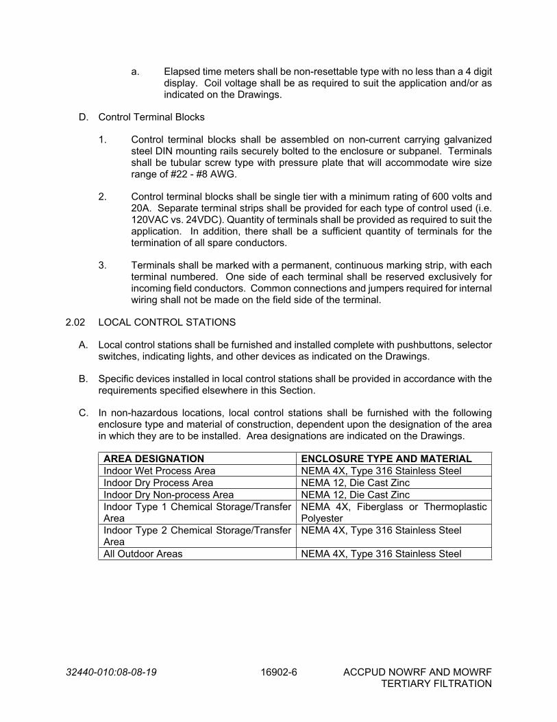
32440-010:08-08-19 16902-6 ACCPUD NOWRF AND MOWRFTERTIARY FILTRATION
a. Elapsed time meters shall be non-resettable type with no less than a 4 digit display. Coil voltage shall be as required to suit the application and/or as indicated on the Drawings.
D. Control Terminal Blocks
1. Control terminal blocks shall be assembled on non-current carrying galvanized steel DIN mounting rails securely bolted to the enclosure or subpanel. Terminals shall be tubular screw type with pressure plate that will accommodate wire size range of #22 - #8 AWG.
2. Control terminal blocks shall be single tier with a minimum rating of 600 volts and 20A. Separate terminal strips shall be provided for each type of control used (i.e. 120VAC vs. 24VDC). Quantity of terminals shall be provided as required to suit the application. In addition, there shall be a sufficient quantity of terminals for the termination of all spare conductors.
3. Terminals shall be marked with a permanent, continuous marking strip, with each terminal numbered. One side of each terminal shall be reserved exclusively for incoming field conductors. Common connections and jumpers required for internal wiring shall not be made on the field side of the terminal.
2.02 LOCAL CONTROL STATIONS
A. Local control stations shall be furnished and installed complete with pushbuttons, selector switches, indicating lights, and other devices as indicated on the Drawings.
B. Specific devices installed in local control stations shall be provided in accordance with the requirements specified elsewhere in this Section.
C. In non-hazardous locations, local control stations shall be furnished with the following enclosure type and material of construction, dependent upon the designation of the area in which they are to be installed. Area designations are indicated on the Drawings.
AREA DESIGNATION ENCLOSURE TYPE AND MATERIALIndoor Wet Process Area NEMA 4X, Type 316 Stainless SteelIndoor Dry Process Area NEMA 12, Die Cast ZincIndoor Dry Non-process Area NEMA 12, Die Cast ZincIndoor Type 1 Chemical Storage/Transfer Area
NEMA 4X, Fiberglass or Thermoplastic Polyester
Indoor Type 2 Chemical Storage/Transfer Area
NEMA 4X, Type 316 Stainless Steel
All Outdoor Areas NEMA 4X, Type 316 Stainless Steel

32440-010:08-08-19 16902-7 ACCPUD NOWRF AND MOWRFTERTIARY FILTRATION
D. In hazardous locations, local control stations shall be furnished with the following enclosure type and material of construction, dependent upon the classification of the area in which they are to be installed. Area classifications are indicated on the Drawings.
AREA CLASSIFICATION ENCLOSURE TYPE AND MATERIALClass 1, Division 1, Group D NEMA 7, Die Cast AluminumClass 1, Division 2, Group D NEMA 4X, Type 304 Stainless SteelClass 2, Division 1, Group F NEMA 9, Die Cast AluminumClass 2, Division 2, Group F NEMA 9, Die Cast Aluminum
E. Non-metallic enclosures, NEMA 7 enclosures, and NEMA 9 enclosures shall be provided with threaded integral conduit hubs. Conduit hubs shall be external to the enclosure.
F. Local control stations for use in non-hazardous locations shall be UL-508 Listed. Local control stations for use in Class 1 Division 1 and Class 2 Divisions 1/2 hazardous locations shall be UL-1203 Listed. Local control stations for use in Class 1 Division 2 hazardous locations shall be in accordance with ANSI/ISA 12.12.01-2013.
G. Provide a nameplate on each local control station in accordance with Section 16195, Electrical Identification. The name and/or number of the equipment associated with each control station shall be engraved on the nameplate, followed by the words “LOCAL CONTROL STATION”.
PART 3 -- EXECUTION
3.01 INSTALLATION
A. Local control stations shall be provided in the enclosure type and material of construction required for the area in which it is installed. Reference the requirements in Part 2 herein, and the area designations indicated on the Drawings.
B. All control components shall be mounted in a manner that will permit servicing, adjustment, testing, and removal without disconnecting, moving, or removing any other component. Components mounted on the inside of panels shall be mounted on removable plates and not directly to the enclosure. Mounting shall be rigid and stable unless shock mounting is required otherwise by the manufacturer to protect equipment from vibration. Component's mounting shall be oriented in accordance with the component manufacturer's and industries' standard practices.
C. Pilot devices shall be properly bonded to the equipment enclosure door where they are installed. If proper bonding cannot be achieved through the locknuts that affix the device in place, a green colored bonding screw shall be provided on the pilot device. The bonding screw shall be bonded to the equipment enclosure through the use of an insulated green bonding conductor.
D. Local control station covers shall be bonded to the local control station enclosure through the use of an insulated green bonding conductor.

32440-010:08-08-19 16902-8 ACCPUD NOWRF AND MOWRFTERTIARY FILTRATION
E. Wiring to devices at each local control station shall be provided with enough slack to permit the local control station cover to be removed and pulled at least 6 inches away from the enclosure.
F. Terminal strips, relays, timers, and similar devices shall not be installed on the rear of the panel/cabinet doors. Terminal strips, relays, timers, and similar devices shall not be installed on the side walls of panel/cabinet interiors without written permission from the Engineer.
- END OF SECTION -

32440-010:08-01-2019 17000-1 ACCPUD NOWRF AND MOWRF
TERTIARY FILTRATION
SECTION 17000
CONTROL AND INFORMATION SYSTEM SCOPE AND GENERAL REQUIREMENTS
PART 1 -- GENERAL 1.01 SCOPE
A. The Contractor shall provide, through the services of an instrumentation and control system subcontractor, all components, system installation services, as well as all required and specified ancillary services in connection with the Instrumentation, Control and Information System. The System includes all materials, labor, tools, fees, charges and documentation required to furnish, install, test and place in operation a complete and operable instrumentation, control and information system as shown and/or specified. The system shall include all measuring elements, signal converters, transmitters, local control panels, digital hardware and software, operator workstations, remote telemetry units, signal and data transmission systems, interconnecting wiring and such accessories as shown, specified, and/or required to provide the functions indicated.
B. The scope of the work to be performed under this Division includes but is not limited to
the following:
1. The Contractor shall retain overall responsibility for the instrumentation and control system as specified herein.
2. Furnish and install process instrumentation and associated taps and supports as
scheduled or shown on the Drawings, unless otherwise noted or supplied by equipment vendors.
3. Scope of work for Middle Oconee WRF includes modifications to the fiber optic
network and the addition of a PLC in the Electrical Building for interface with manufacturer-provided filter PLCs and with equipment at the Rapid Mix and Flocculation Basins and Filter Influent Pump Station. Three tertiary filter package systems are provided to treat secondary clarifier effluent prior to UV disinfection, preceded by a Filter Influent Pump Station and Rapid Mix and Flocculation Tanks. A dedicated alum storage and pumping facility will provide chemical receipt and distribution for the filters.
4. Scope of work for North Oconee WRF includes modifications to the fiber optic
network and the addition of a PLC at the UV facility with an operator interface terminal for interface with manufacturer-provided filter PLCs and with equipment at the Rapid Mix and Flocculation Basins. Three tertiary filter package systems are provided to treat secondary clarifier effluent prior to UV disinfection, preceded by Rapid Mix and Flocculation Tanks. Modifications to the existing alum storage and pumping facility will provide chemical receipt and distribution for the filters.
32440-010:08-01-2019 17000-2 ACCPUD NOWRF AND MOWRF
TERTIARY FILTRATION
5. Furnish and install local control panels, field panels and associated cabinets and panels as shown on the Drawings and as specified in Division 17.
6. Furnish and install digital control system hardware and software as specified in
Division 17. 7. Final termination and testing of all instrumentation and control system signal
wiring and power supply wiring at equipment furnished under Division 17. 8. Furnish, install and terminate all special cables (instruments, printers, telemetry,
etc.). Furnish and terminate control system communication network cables. 9. Furnish and install surge protection devices for all digital equipment, local control
panels, and instrumentation provided under this Division, including connections to grounding system(s) provided under Division 16.
10. Coordinate grounding requirements with the electrical subcontractor for all digital
equipment, local control panels, and instrumentation provided under this Division. Terminate grounding system cables at all equipment provided under this Division.
11. Provide system testing, calibration, training and startup services as specified
herein and as required to make all systems fully operational.
C. It is the intent of the Contract Documents to construct a complete and working installation. Items of equipment or materials that may reasonably be assumed as necessary to accomplish this end shall be supplied whether or not they are specifically stated herein.
1.02 RELATED ITEMS
A. Field mounted switches, torque switches, limit switches, gauges, valve and gate operator position transmitters, and other instrumentation and controls furnished with mechanical or electrical equipment not listed in the instrument schedule shall be furnished, installed, tested and calibrated as specified under other Divisions.
B. Additional and related work performed under Division 16 includes the following:
1. Instrument A.C. power source and disconnect switch for process instrumentation,
A.C. grounding systems, and A.C. power supplies for all equipment, control panels and accessories furnished under Division 17.
2. Conduit and raceways for all instrumentation and control system signal wiring,
grounding systems, special cables and communication network cables. 3. Instrumentation and control system signal wiring. 4. Install control system communication network cables.
05
12
15
BR

32440-010:08-01-2019 17000-3 ACCPUD NOWRF AND MOWRF
TERTIARY FILTRATION
5. Furnish and install grounding systems for all digital equipment, local control panels, and instrumentation provided under Division 17. Grounding systems shall be complete to the equipment provided under Division 17, ready for termination by the instrumentation subcontractor.
6. Termination of all instrumentation and control system signal wiring at all
equipment furnished under other divisions of the Specifications. 7. Final wiring and termination to A.C. grounding systems and to A.C. power
sources (e.g. panelboards, motor control centers, and other sources of electrical power).
1.03 GENERAL INFORMATION AND DESCRIPTION
A. Where manufacturers are named for a particular item of equipment, it is intended as a guide to acceptable quality and performance and does not exempt such equipment from the requirements of these Specifications or Drawings.
B. In order to centralize responsibility, it is required that all equipment (including field
instrumentation and control system hardware and software) offered under this Division shall be furnished and installed by the instrumentation subcontractor, or under the supervision of the instrumentation subcontractor, who shall assume complete responsibility for proper operation of the instrumentation and control system equipment, including that of coordinating all signals, and furnishing all appurtenant equipment.
C. The Contractor shall retain total responsibility for the proper detailed design, fabrication,
inspection, test, delivery, assembly, installation, activation, checkout, adjustment and operation of the entire instrumentation and control system as well as equipment and controls furnished under other Divisions of the Specifications. The Contractor shall be responsible for the delivery of all detailed drawings, manuals and other documentation required for the complete coordination, installation, activation and operation of mechanical equipment, equipment control panels, local control panels, field instrumentation, control systems and related equipment and/or systems and shall provide for the services of a qualified installation engineer to supervise all activities required to place the completed facility in stable operation under full digital control.
D. The instrumentation and control system shall be capable of simultaneously implementing
all real-time control and information system functions, and servicing all operator service requests as specified, without degrading the data handling and processing capability of any system component.
E. Control system inputs and outputs are listed in the Input/Output Schedule. This
information, together with the functional control descriptions, process and instrumentation diagrams, and electrical control schematics, describes the real-time monitoring and control functions to be performed. In addition, the system shall provide various man/machine interface and data reporting functions as specified in the software sections of this Specification.
F. The mechanical, process, and electrical drawings indicate the approximate locations of
field instruments, control panels, systems and equipment as well as field-mounted

32440-010:08-01-2019 17000-4 ACCPUD NOWRF AND MOWRF
TERTIARY FILTRATION
equipment provided by others. The instrumentation subcontractor shall examine the mechanical, process and electrical drawings to determine actual size and locations of process connections and wiring requirements for instrumentation and controls furnished under this Contract. The instrumentation subcontractor shall inspect all equipment, panels, instrumentation, controls and appurtenances either existing or furnished under other Divisions of the Specifications to determine all requirements to interface same with the control and information system. The Contractor shall coordinate the completion of any required modifications with the associated supplier of the item furnished.
G. The instrumentation subcontractor shall review and approve the size and routing of all
instrumentation and control cable and conduit systems furnished by the electrical subcontractor for suitability for use with the associated cable system.
H. The Contractor shall coordinate the efforts of each supplier to aid in interfacing all
systems. This effort shall include, but shall not be limited to, the distribution of approved shop drawings to the electrical subcontractor and to the instrumentation subcontractor furnishing the equipment under this Division.
I. The Contractor shall be responsible for providing a signal transmission system free from
electrical interference that would be detrimental to the proper functioning of the instrumentation and control system equipment.
J. The Owner shall have the right of access to the subcontractor's facility and the facilities
of his equipment suppliers to inspect materials and parts; witness inspections, tests and work in progress; and examine applicable design documents, records and certifications during any stage of design, fabrication and tests. The instrumentation subcontractor and his equipment suppliers shall furnish office space, supplies and services required for these surveillance activities.
K. The terms "Instrumentation", "Instrumentation and Control System", and
"Instrumentation, Control and Information System" shall hereinafter be defined as all equipment, labor, services and documents necessary to meet the intent of the Specifications.
1.04 INSTRUMENTATION AND CONTROL SYSTEM SUBCONTRACTORS
A. Instrumentation and control system subcontractors shall be regularly engaged in the detailed design, fabrication, installation, and startup of instrumentation and control systems for water and wastewater treatment facilities. Instrumentation and control system subcontractors shall have a minimum of five years of such experience and shall have completed a minimum of three projects of similar type and size as that specified herein. Where specific manufacturers and/or models of major hardware or software products (PLC, HMI software, LAN, etc.) are specified to be used on this project, the instrumentation and control system subcontractor shall have completed at least one project using that specified hardware or software. As used herein, the term “completed” shall mean that a project has been brought to final completion and final payment has been made. Any instrumentation and control system subcontractor that has been subject to litigation or the assessment of liquidated damages for nonperformance on any project within the last five calendar years shall not be acceptable.

32440-010:08-01-2019 17000-5 ACCPUD NOWRF AND MOWRF
TERTIARY FILTRATION
B. Acceptable instrumentation and control system subcontractors shall be Kapsch Controls, Inc.; no others will be accepted.
1.05 DEFINITIONS
A. Solid State: Wherever the term solid state is used to describe circuitry or components in the Specifications, it is intended that the circuitry or components shall be of the type that convey electrons by means of solid materials such as crystals or that work on magnetic principles such as ferrite cores. Vacuum tubes, gas tubes, slide wires, mechanical relays, stepping motors or other devices will not be considered as satisfying the requirements for solid state components of circuitry.
B. Bit or Data Bit: Whenever the terms bit or data bit are used in the Specification, it is
intended that one bit shall be equivalent to one binary digit of information. In specifying data transmission rate, the bit rate or data bit rate shall be the number of binary digits transmitted per second and shall not necessarily be equal to either the maximum pulse rate or average pulse rate.
C. Integrated Circuit: Integrated circuit shall mean the physical realization of a number of
circuit elements inseparably associated on or within a continuous body to perform the function of a circuit.
D. Mean Time Between Failures (MTBF): The MTBF shall be calculated by taking the
number of system operating hours logged during an arbitrary period of not less than six months and dividing by the number of failures experienced during this period plus one.
E. Mean Time to Repair (MTTR): The MTTR shall be calculated by taking the total system
down time for repair over an arbitrary period of not less than six months coinciding with that used for calculation of MTBF and dividing by the number of failures causing down time during the period.
F. Availability: The availability of a non-redundant device or system shall be related to its
MTBF and MTTR by the following formula:
A = 100 x (MTBF/(MTBF + MTTR)) Percent
The availability of a device or system provided with an automatically switched backup device or system shall be determined by the following formula:
A = A2 + 1 - ((1-A1) x (1-A1))
where:
A1 = availability of non-redundant device or system A2 = availability of device or system provided with an automatically
switched backup device or system

32440-010:08-01-2019 17000-6 ACCPUD NOWRF AND MOWRF
TERTIARY FILTRATION
G. Abbreviations: Specification abbreviations include the following:
A - Availability
ADC - Analog to Digital Converter
AI - Analog Input
AO - Analog Output
AVAIL - Available
BCD - Binary Coded Decimal
CSMA/CD - Carrier Sense Multiple Access/Collision Detect
CPU - Central Processing Unit
CRC - Cyclic Redundancy Check
CRT - Cathode Ray Tube
CS - Control Strategy
DAC - Digital to Analog Converter
DBMS - Data Base Management System
DI - Discrete Input
DMA - Direct Memory Access
DO - Discrete Output
DPDT - Double Pole, Double Throw
DVE - Digital to Video Electronics
EPROM - Erasable, Programmable Read Only Memory
FDM - Frequency Division Multiplexing
FSK - Frequency Shift Keyed
HMI - Human Machine Interface (Software)
I/O - Input/Output
LAN - Local Area Network
LDFW - Lead-Follow
MCC - Motor Control Center
MTBF - Mean Time Between Failures
MTTR - Mean Time To Repair
OS - Operating System
PAC - Programmable Automation Controller
PCB - Printed Circuit Board
PID - Proportional Integral and Derivative Control
PLC - Programmable Logic Controller

32440-010:08-01-2019 17000-7 ACCPUD NOWRF AND MOWRF
TERTIARY FILTRATION
PROM - Programmable Read Only Memory
RAM - Random Access Memory
RDY - Ready
RMSS - Root Mean Square Summation
RNG - Running
ROM - Read Only Memory
RTU - Remote Telemetry Unit
SPDT - Single Pole, Double Throw
ST/SP - Start/Stop
TDM - Time Division Multiplexing
UPS - Uninterruptible Power Supply
H. To minimize the number of characters in words used in textual descriptions on CRT
displays, printouts and nameplates, abbreviations may be used subject to the Engineer's approval. If a specified abbreviation does not exist for a particular word, an abbreviation may be generated using the principles of masking and or vowel deletion. Masking involves retaining the first and last letters in a word and deleting one or more characters (usually vowels) from the interior of the word.
1.06 ENVIRONMENTAL CONDITIONS
A. Instrumentation equipment and enclosures shall be suitable for ambient conditions specified. All system elements shall operate properly in the presence of telephone lines, power lines, and electrical equipment.
B. Inside control rooms and climate-controlled electrical rooms, the temperature will
normally be 20 to 25 degrees C; relative humidity 40 to 80 percent without condensation and the air will be essentially free of corrosive contaminants and moisture. Appropriate air filtering shall be provided to meet environmental conditions (i.e., for dust).
C. Other indoor areas may not be air conditioned/heated; temperatures may range between
0 and 40 degrees C with relative humidity between 40 and 95 percent.
D. Field equipment including instrumentation and panels may be subjected to wind, rain, lightning, and corrosives in the environment, with ambient temperatures from -20 to 40 degrees C and relative humidity from 10 to 100 percent. All supports, brackets, interconnecting hardware, and fasteners shall be aluminum, type 316 stainless steel, or metal alloy as otherwise suitable for chemical resistance within chemical feed/storage areas shown on the installation detail drawings.
PART 2 -- PRODUCTS 2.01 NAMEPLATES

32440-010:08-01-2019 17000-8 ACCPUD NOWRF AND MOWRF
TERTIARY FILTRATION
A. All items of equipment listed in the instrument schedule, control panels, and all items of digital hardware shall be identified with nameplates. Each nameplate shall be located so that it is readable from the normal observation position and is clearly associated with the device or devices it identifies. Nameplates shall be positioned so that removal of the device for maintenance and repair shall not disturb the nameplate. Nameplates shall include the equipment identification number and description. Abbreviations of the description shall be subject to the Engineer's approval.
B. Nameplates shall be made of 1/16-inch thick machine engraved laminated phenolic
plastic having white numbers and letters not less than 3/16-inch high on a black background.
C. Nameplates shall be attached to metal equipment by stainless steel screws and to other
surfaces by an epoxy-based adhesive that is resistant to oil and moisture. In cases where the label cannot be attached by the above methods, it shall be drilled and attached to the associated device by means of stainless steel wire.
PART 3 -- EXECUTION 3.01 SCHEDULE OF PAYMENT
A. Payment to the Contractor for Control and Information System materials, equipment, and labor shall be in accordance with the General and Supplementary Conditions. The schedule of values submitted as required by the General and Supplementary Conditions shall reflect a breakdown of the work required for completion of the Control and Information System. The breakdown shall include sufficient detail to permit the Engineer to administer payment for the Control and Information System as outlined below.
B. The following payment schedule defines project milestones that will be used for
establishing maximum partial payment amounts for the Control and Information System. Payment for field instruments, field wiring, fiber optic network cable and similar items will be made in addition to the payment for the scopes of services incorporated into the schedule below.
Task Completed Maximum Cumulative %
Request for Payment
Mobilization 3%
Preliminary Design Review 5%
Approved Submittals 20%
Hardware Purchase (excludes field instruments) 40%
Factory Acceptance Test 60%
Loop Checkout 70%
Control System Start-up and Test 80%
Plant Start-up 90%
Final System Acceptance Test 95%

32440-010:08-01-2019 17000-9 ACCPUD NOWRF AND MOWRF
TERTIARY FILTRATION
Final Acceptance 100%
C. Requests for payment for materials and equipment that are not installed on site, but are
required for system construction and the factory acceptance test (e.g., digital hardware), or are properly stored as described in the General and Supplementary Conditions and herein, shall be accompanied by invoices from the original supplier to the instrumentation subcontractor substantiating the cost of the materials or equipment.
D. Any balance remaining within the schedule of values for field instruments and other
materials installed on the site, or for other materials for which payment is made by invoice, will be considered due upon completion of the Final Acceptance test.
3.02 CLEANING
A. The Contractor shall thoroughly clean all soiled surfaces of installed equipment and materials.
B. Upon completion of the instrumentation and control work, the Contractor shall remove all
surplus materials, rubbish, and debris that has accumulated during the construction work. The entire area shall be left neat, clean, and acceptable to the Owner.
3.03 FINAL ACCEPTANCE
A. Final acceptance of the Instrumentation, Control and Information System will be determined complete by the Engineer, and shall be based upon the following:
1. Receipt of acceptable start up completion and availability reports and other
documentation as required by the Contract Documents. 2. Completion of the Availability Demonstration. 3. Completion of all specified control system training requirements. 4. Completion of all punch-list items that are significant in the opinion of the
Engineer.
B. Final acceptance of the System shall mark the beginning of the extended warranty period.
- END OF SECTION -

32440-010:08-08-2019 17120-1 ACCPUD NOWRF AND MOWRF TERTIARY FILTRATION
SECTION 17120
PROGRAMMABLE LOGIC CONTROLLERS
PART 1 -- GENERAL 1.01 THE REQUIREMENT
A. The Contractor shall furnish, test, install and place in satisfactory operation all programmable logic controllers, with all spare parts, accessories, and appurtenances as herein specified and as shown on the Drawings.
1.02 RELATED WORK SPECIFIED ELSEWHERE
A. Section 17000 – Control and Information System Scope and General Requirements
B. Section 17060 – Signal Coordination Requirements
C. Section 17100 – Control and Information System Hardware - General
D. Section 17125 – Operator Interface Units
E. Section 17180 – Process Control System Networks
F. Section 17190 – Uninterruptible Power Systems
G. Section 17500 – Enclosures, General 1.03 TOOLS, SUPPLIES AND SPARE PARTS
A. Tools, supplies and spare parts shall be provided as specified in Section 17050 - Tools, Supplies, and Spare Parts. In addition, the following specific spare parts items shall be provided:
1. One of each type and size of module for PLC equipment furnished under this
Contract. 2. One of each type and size of PLC and equipment power supply furnished under
this Contract.
PART 2 -- PRODUCTS
2.01 PROGRAMMABLE LOGIC CONTROLLERS - GENERAL
A. The instrumentation subcontractor shall furnish programmable controllers (PLC's) as specified herein and as shown on the Drawings. PLC's shall be provided complete with backplane, power supply, I/O cards, special function cards, instructions, memory, input/output capacity, and appurtenances to provide all features and functions as described herein. No substitutions will be permitted.
06
19
17
BR

32440-010:08-08-2019 17120-2 ACCPUD NOWRF AND MOWRF TERTIARY FILTRATION
B. All components of the PLC system shall be of the same manufacturer; who shall have fully tested units similar to those being furnished in an industrial environment with associated electrical noise. The PLC system shall have been tested to meet the requirements of NEMA Standard ICS 2-230 (Arc Test) and IEEE C37.90.1 (SWC). The processing unit shall perform the operations functionally described herein based on the program stored in memory and the status of the inputs and outputs.
C. Programmable controllers shall be designed to operate in an industrial environment. The
PLC shall operate in an ambient temperature range of 0°-60°C and a relative humidity of 5-95 percent, non-condensing. The PLC shall operate on supply voltages of 90-132 VAC at 47-63 Hz or 24 VDC if provided with a battery backup system. An integral fuse shall be provided on the power supply for short circuit protection and shall be front panel accessible. Integral overcurrent and undervoltage protection shall be provided on the power supply.
D. Where applicable, the minimum PLC backplane size shall be 7 slots, not including power
supply slots.
E. System configuration shall be as shown on the Control System Architecture Drawing. PLC types shall be designated on the Control System Architecture Drawing and correspond to the specifications herein. Only a single type of processor shall be supplied for all PLCs of a designated type. Memory and processor shall be adequate for all control functions specified. PLCs shall be as manufactured or equal to the following: 1. Allen-Bradley ControlLogix
2.02 PROCESSORS
A. The processor and its associated memory shall be enclosed in a modular enclosure. A multiple-position selector switch or equivalent shall be used to select processor operating mode. LED-type indicating lights shall be provided to indicate processor, memory, and battery status. Errors in memory shall be recognized and shall activate the memory error indicating lights. The PLC processor shall monitor the internal operation of the PLC for failure and provide an alarm output. Nonvolatile memory in the form of a manufacturer supplied industrial CompactFlash card or equivalent technology shall be required to maintain the entire current program and firmware of the controller in the event of power loss. The program shall be updated onto the flash memory each time a program change such as an online edit or tag value is changed. When nonvolatile memory (flash memory) is not available for certain controller models as offered by the PLC manufacturer, lithium batteries shall be used to maintain process RAM memory for at least one year in the event of power loss. The lithium battery unit shall be an externally mounted battery assembly with the highest available capacity. The PLC shall send an alarm to the plant control system if battery level is low.
B. The instruction set for the PLC shall conform to the requirements of IEC 61131-3. Each
PLC shall have the capability to run all five of the standard IEC 61131-3 languages simultaneously. These five languages shall be:
1. Ladder Diagram 2. Structured Text 3. Instruction List

32440-010:08-08-2019 17120-3 ACCPUD NOWRF AND MOWRF TERTIARY FILTRATION
4. Function Block Diagram 5. Sequential Function Chart
C. Additional co-processors or modules may be necessary and shall be furnished as
required to meet the functions specified herein and in Section 17950 – Functional Control Descriptions.
D. PLC processors shall be provided with substantial user program, data and logic memory
to allow for future expansion of the overall system. The total memory used on each processor shall be less than 60% of available memory at project completion.
2.03 COMMUNICATIONS
A. PLC communications shall be provided as specified in Section 17180 – Process Control System Networks and as shown on the Control System Architecture Drawing.
B. In addition to a communications port for the control system network, communication ports
shall be provided for any other devices required (i.e., operator interface unit) plus an additional communication port for connection to a notebook computer.
C. The PLC shall be able to support various types of fieldbus communication systems for
data links to field instruments (where specified) in addition to connected equipment such as power monitors, VFDs, motor protection monitors, etc. As a minimum, Profibus DP, Foundation Fieldbus, Modbus RTU Master and Slave, TCP/IP Ethernet shall be supported. The Contractor shall coordinate the efforts of the necessary parties (instrumentation subcontractor and equipment suppliers) to accomplish the required device and data table addressing between each PLC and the associated connected equipment.
D. Additional communication modules or protocol gateways may be required to support specific communication protocols required under this Contract and shall be supplied at no extra cost to the Owner.
2.04 INPUT/OUTPUT SUBSYSTEMS
A. Input/output hardware shall be plug-in modules in associated I/O backplane/chassis or DIN-rail mounting assemblies. Each unit shall handle the required number of process inputs and outputs plus a minimum of 10 percent active pre-wired spares for each I/O type furnished, plus a minimum of 20 percent spare I/O module space for the addition of future circuit cards or modules.
B. Discrete inputs shall be 24 VDC or 120 VAC signals (integral to the PLC) from dry field
contacts. Discrete outputs shall be 24 VDC or 120 VAC outputs sourced from the PLC, or dry relay contacts (2A minimum) as required. Refer to Section 17060 – Signal Coordination Requirements for further details of discrete signal type and voltage requirements. The PLC shall provide momentary and latched outputs as required to interface with motor controls and external devices. Interposing relays shall be provided where required to interface with field equipment. Interposing relays shall be as specified in Section 17550. Electrical isolation shall be provided where required. Maximum density for discrete I/O modules shall be 32 per input module and 16 per output module.

32440-010:08-08-2019 17120-4 ACCPUD NOWRF AND MOWRF TERTIARY FILTRATION
C. Analog input circuits shall be isolated, minimum 16-bit resolution type. Analog input hardware shall be provided as required for all types of analog inputs being transmitted to the PLC. In general, analog input modules shall be capable of receiving 4-20 mA signals.
Where required, RTD input modules shall have a minimum resolution of 0.15°C and be capable of accepting signals from 100-ohm Platinum RTD’s. Analog outputs shall be coordinated with the receivers but shall generally be isolated 24 VDC 4-20 mA outputs powered from the PLC. Each input/output circuit shall have optical isolation to protect the equipment against high voltage transients. Optical isolation shall be rated at not less than 1500 V RMS. Lightning/surge protection shall be provided as specified in Section 17560 - Surge Protection Devices. Maximum density for analog I/O modules shall be 8 per module.
D. Input/output modules shall be configured for ease of wiring and maintenance. The
modules shall be connected to wiring arms that can be disconnected to permit removal of a module without disturbing field wiring. Covers shall be provided to prevent operator personnel from inadvertently touching the terminals. The process interface modules shall be provided with screw-type terminal blocks with barriers between adjacent terminals for connection of field inputs. Terminals shall be suitable for accepting up to and including No. 14 AWG wire. All DC output circuits to the field shall include fuses, either integral or at the terminal strip. Output failure mode shall be selectable so that upon station or communication system failure all outputs shall be placed either in the non-conducting mode or remain as were prior to failure. Light-emitting diodes shall be provided for status indication for each input and output point.
E. External power supplies shall be provided with the PLC as required to meet specified
installed I/O power requirements plus spares. Power supplies shall be modular units, shall be fully redundant and shall alarm the PLC upon failure. Power supplies shall have a line regulation of 0.05% and meet the environmental and power requirements specified herein for the PLC.
2.05 REMOTE I/O SUBSYSTEMS
A. Remote I/O shall be provided as designated on the Control System Architecture Drawing. Remote I/O shall be either PLC backplane type I/O or field modules as manufactured by the PLC manufacturer. Field modules shall meet the requirements of Subsection 2.04, Input/Output Subsystems. Remote I/O processor or communication modules shall be modular and individually replaceable.
B. Remote I/O shall communicate with the PLC using the PLC manufacturer’s standard
protocol or an open standard network such as DeviceNet, Ethernet IP, ProfiNet, Foundation Fieldbus, Modbus TCP/IP, or equal.

32440-010:08-08-2019 17120-5 ACCPUD NOWRF AND MOWRF TERTIARY FILTRATION
2.06 INPUT/OUTPUT CIRCUIT ARRANGEMENT
A. Signal and control circuitry to individual input/output boards shall be arranged such that board failure shall not disable more than one half of the control loops within any group of controlled equipment (e.g., one pump out of a group of three pumps, two pumps out of four, etc.). Where possible, individual control loops and equipment shall be assigned to individual boards such that failure of the board will disable only one loop or piece of equipment.
2.07 PROGRAMMING SOFTWARE
A. The PLC programming and configuration software shall be the manufacturer's latest, full-featured version, Windows-based, and shall be fully compliant with IEC 61131-3 standards. The software package shall consist of all programming, configuration, and documentation software needed to place the control and information system in satisfactory operation. The software shall allow on-line and off-line program development and documentation. PLC programming software shall include documentation on optical media.
B. A minimum of one copy of the PLC programming software shall be purchased by the
instrumentation subcontractor and registered to the Owner.
C. All configuration and programming software necessary shall be provided on the computer specified in Section 17170 – Portable Notebook Computers for connection to the PLC processor via a communications port. All necessary hardware required to allow the notebook computer to perform PLC configuration and programming shall be provided.
D. If available, the configuration and programming software shall support communication
over the network specified in Section 17180 – Process Control System Networks to implement its functions remotely from an operator workstation. All configuration and programming software necessary to implement this functionality shall be provided on the HMI Server operator workstations specified in Section 17140 – Operator Workstations. All necessary hardware required to have the operator workstation perform PLC configuration and programming shall be provided.
PART 3 - EXECUTION 3.01 REQUIREMENTS
A. PLC programming shall be furnished to perform all functions described in Section 17950 – Functional Control Descriptions, including global functions. In addition, PLCs shall be programmed to provide additional functions described in other sections of this Division.
B. PLC programming shall make use of the various IEC languages as appropriate to the
specific task and shall be performed in a modular style making extensive use of program blocks (subroutines) and program variables to be passed to the program blocks for specific equipment. It is the intent of this requirement to allow for enhanced readability and ease of modification of the program code through the elimination of multiple instances of repeated code for the same function in a “hard-coded” style.

32440-010:08-08-2019 17120-6 ACCPUD NOWRF AND MOWRF TERTIARY FILTRATION
C. Extensive comments shall be placed in the program code to describe the functions of all elements of the program code. PLC code that does not contain comments shall be rejected.
D. Refer to Section 17000, Part 3 for additional requirements.
3.02 REQUIREMENTS FOR MANUFACTURER-SUPPLIED PLCs
A. PLCs that are supplied for equipment local control panels by individual equipment manufacturers or suppliers shall, where so indicated on the Control System Architecture Drawing, be integrated into the plant control system. The manufacturer-supplied PLC shall be furnished, installed and programmed by the manufacturer. The PLC shall continuously monitor and control the associated system and at the same time shall provide all the required alarms, indications of system parameters, equipment status, etc. to the main control system at the plant.
B. Where required as described above, each manufacturer-supplied PLC shall be connected
to the Ethernet process control network for access from the plant control system HMI servers, as specified in Section 17180, and shall contain a fiber optic Ethernet switch identical to those provided for the rest of the network-connected PLCs.
C. Each equipment manufacturer shall provide all monitoring and control data to be transferred between the PLC and the plant control system in contiguous blocks of PLC registers to facilitate block read and write commands for efficient scanning by the control system SCADA servers. These contiguous registers shall be arranged in a single data transfer area, which shall be divided into eight distinct areas with an emphasis on flexibility and future expansion. The distinct areas shall be arranged by data type (analog or discrete), transfer direction (server to PLC or PLC to server), and, where applicable, implementation schedule (current or future). Where required, peer-to-peer communication between PLCs shall likewise be accomplished using separate blocks of contiguous registers. Where individual equipment PLCs are not required to be connected to the plant control system via the data highway network, they shall provide the individual hardwired signals as specified in the Contract Documents. Data and commands for connection to the control system are described in the Drawings, the Input/Output Schedule, the individual equipment specification sections, and in Section 17950 – Functional Control Descriptions.
D. The operator interface for control of each individual system shall be performed by local
operator interface units as specified in Section 17125 or individual pilot devices on the equipment local control panel, as specified in the associated equipment specification section. Additional operator interface functions shall be provided through the plant control system as specified in the respective equipment specifications and in Section 17950.
E. Where operator interface and control functions are required to be provided through the
plant control system, the individual system supplier shall be responsible for coordination with the instrumentation subcontractor to provide a complete and working equipment control system. The individual equipment supplier shall also be responsible for limiting the access of the plant control system to the equipment PLC code so as to prevent malfunctions of the equipment and any failure to continuously perform its intended functions. The equipment supplier shall be responsible for ensuring that no actions by the plant control system can damage or otherwise adversely affect the operation of the

32440-010:08-08-2019 17120-7 ACCPUD NOWRF AND MOWRF TERTIARY FILTRATION
associated equipment or the safety of personnel working on or near that equipment. The equipment supplier shall also provide direction in the configuration of the SCADA software’s security system by the instrumentation subcontractor to limit access to the control functions of the equipment control system to authorized personnel only. The equipment supplier shall coordinate testing of the completed system with the instrumentation subcontractor, which shall conform to the requirements of Section 17072 – Field Testing.
F. The Contractor, equipment supplier and instrumentation subcontractor shall coordinate
testing and startup of the equipment provided by the equipment supplier with the plant control system, including but not limited to the following tasks:
1. Provide assistance with control system testing of inputs, outputs, and control
strategies as needed.
2. Provide support or interface work necessary to perform physical checkout and field testing to the final field devices. The schedule may require the instrumentation subcontractor and equipment manufacturer personnel to perform loop checks simultaneously, as directed by the Engineer.
3. Coordinate and assist as needed to maintain I/O connectivity throughout the
system.
4. Ensure personnel safety while equipment is exercised via the plant control system.
5. Ensure that process, instrumentation, and control equipment are not damaged while equipment is exercised via the plant control system.
6. Provide temporary modifications to field devices and their terminations, if needed.
7. Providing labor and supervision, which may include, but is not limited to, the
following: electricians, instrument technicians, manufacturer’s representatives, and individual(s) knowledgeable about process startup and operation.
8. Operation of process equipment for verification of each plant control system input
and output.
- END OF SECTION -

32440-010:08-01-2019 17125-1 ACCPUD NOWRF AND MOWRF TERTIARY FILTRATION
SECTION 17125
OPERATOR INTERFACE UNITS PART 1 -- GENERAL 1.01 THE REQUIREMENT
A. The Contractor shall furnish, test, install and place in satisfactory operation all operator interface units, with all spare parts, accessories, and appurtenances as herein specified and as shown on the Drawings.
1.02 RELATED WORK SPECIFIED ELSEWHERE
A. Section 17000 – Control and Information System Scope and General Requirements
B. Section 17100 – Digital System Hardware Configuration
C. Section 17120 – Programmable Logic Controllers PART 2 -- PRODUCTS 2.01 OPERATOR INTERFACE UNIT – LARGE
A. An Operator Interface Unit (OIU) shall be provided to view and change PLC monitoring and control parameters and to display alarm messages using a graphical user interface. The OIU shall provide the following features as a minimum:
1. Minimum of 10.4-inch diagonal display.
2. 18-bit color TFT LCD display of 640 X 480 pixels.
3. Resistive film touch screen interface.
4. Minimum of 512 MB internal storage.
5. Minimum of 512 MB RAM application memory.
6. 1.0 GHz CPU.
7. Windows CE Operating System.
8. Battery-backed real-time clock.
9. SD, 2 USB-A, 1 Mini-USB-B, and PCI interfaces.
10. RJ-45 Ethernet communication interface, 10/100 Mb auto selecting.
06
22
17
BR

32440-010:08-01-2019 17125-2 ACCPUD NOWRF AND MOWRF TERTIARY FILTRATION
11. RS-232 serial port.
12. Sound and buzzer output.
13. Windows-based configuration software complete with download cable.
14. Operating Voltage: 120 VAC or 24 VDC (internal or via independent power supply).
15. Enclosure Rating: NEMA 12/4X to match the associated PLC cabinet rating.
16. Environment: 0-55°C, 5-95% relative humidity, non-condensing.
B. The operator interface unit shall be Allen-Bradley PanelView Plus 6 1000, or equal. 2.02 OPERATOR INTERFACE UNIT – SMALL
A. An Operator Interface Unit (OIU) shall be provided to view and change PLC monitoring and control parameters and to display alarm messages using a graphical user interface. The OIU shall provide the following features as a minimum.
1. Minimum of 6.5-inch diagonal display.
2. 18-bit color TFT LCD display of 640 X 480 pixels.
3. Resistive film touch screen interface.
4. Minimum of 512 MB internal storage.
5. Minimum of 512 MB RAM application memory.
6. 1.0 GHz CPU.
7. Windows CE Operating System.
8. Battery-backed real-time clock.
9. Communication Interfaces:1 SD, 2 USB-A, 1 Mini-USB-B, and 1 PCI.
10. RJ-45 Ethernet communication interface, 10/100 Mb auto selecting.
11. RS-232 serial port.
12. Sound and buzzer output.
13. Windows-based configuration software complete with download cable.
14. Operating Voltage: 120 VAC or 24 VDC (internal or via independent power supply).
15. Enclosure Rating: NEMA 12/4X to match the associated PLC cabinet rating.

32440-010:08-01-2019 17125-3 ACCPUD NOWRF AND MOWRF TERTIARY FILTRATION
16. Environment: 0-55°C, 5-95% relative humidity, non-condensing.
B. The operator interface unit shall be Allen-Bradley PanelView Plus 6 700, or equal.
PART 3 -- EXECUTION 3.01 REQUIREMENTS
A. The OIU shall be configured to display all PLC I/O, setpoints, and parameters. All equipment failures shall be alarmed. PLC I/O values and operator-entered setpoints shall be displayed with associated units and service descriptions. Menus shall be provided to navigate between screens of different equipment items. Displays shall be arranged in a hierarchical structure with displays for specific equipment items grouped together. Additional functionality shall be as specified elsewhere in this Division.
B. All necessary configuration and programming software shall be provided on optical
media and turned over to the Owner.
C. Unless otherwise noted, each OIU shall be mounted between 48 and 60 inches above the floor or work platform.
D. Refer to Section 17000 for additional requirements.
- END OF SECTION -

32440-010:08-01-2019 17125-4 ACCPUD NOWRF AND MOWRF TERTIARY FILTRATION
THIS PAGE
INTENTIONALLY
LEFT BLANK

32440-010:08-08-2019 17180-1 ACCPUD NOWRF AND MOWRF TERTIARY FILTRATION
SECTION 17180
PROCESS CONTROL SYSTEM NETWORKS PART 1 -- GENERAL 1.01 THE REQUIREMENT
A. The Contractor shall furnish, test, install and place in satisfactory operation IEEE 802.3 Ethernet local area network(s) for communications among plant devices.
B. Local area network shall be provided with all spare parts, accessories, and appurtenances
as herein specified. 1.02 RELATED WORK SPECIFIED ELSEWHERE
A. Section 17000 – Control and Information System Scope and General Requirements B. Section 17120 – Programmable Logic Controllers
C. Section 17140 – Operator Workstations
1.03 TOOLS, SUPPLIES AND SPARE PARTS
A. The following specific spare parts items shall be provided:
1. A termination tool kit shall be provided containing all required tools and consumables for up to 25 connections of each connection type furnished. Termination kit shall be as manufactured by Black Box, Corning Cable Systems, Optical Cable Corporation, or equal.
2. One spare switch of each type furnished under this Contract.
PART 2 -- PRODUCTS 2.01 LOCAL AREA NETWORK (LAN)
A. An IEEE 802.3 Ethernet local area network shall be used for communications between plant devices.
B. Network wiring shall be unshielded, twisted-pair copper cables for connections within
buildings. Fiber optic media shall be used for all inter-device communication links extended outside of a building, unless specifically noted. Cables shall be as specified herein.
C. The Contractor may provide a network configuration different from that shown in the
Contract Drawings with written approval of the Engineer, but the Contractor shall coordinate with all affected trades and pay for all additional charges incurred.
12
15
17
BR

32440-010:08-08-2019 17180-2 ACCPUD NOWRF AND MOWRF TERTIARY FILTRATION
D. The Contractor shall supply all hardware, cables, connectors, and software to implement
a network as specified herein and shown on drawings. 2.02 INDUSTRIAL ETHERNET NETWORK SWITCHES
A. Except where specifically allowed on the Control System Architecture Drawing, industrial Ethernet network switches shall be provided for each device connected to the process control system network. The switches shall create switched Ethernet networks that conform to the IEEE 802.3 and 802.3u standards using copper wires or optical fibers in a bus, tree or ring network topology as shown on the Drawings. Ethernet network switches shall be modular, rack mounted, or standard DIN-rail mounted within the PLC cabinet or in an adjacent communication cabinet, as shown on the Drawings.
B. Ethernet network switches shall support ring, bus, tree, or point-to-point network
topologies. On-line signal monitoring shall be provided to detect and locate impending faults. Ethernet network switches shall be replaceable on-line without disrupting the network. The Ethernet network switches shall be integrated into the in-plant Ethernet network to form a redundant ring network with self-healing communication recovery. Switches shall support the non-proprietary Media Redundancy Protocol (MRP) and Rapid Spanning Tree Protocol (RSTP) in addition to the switch manufacturer’s standard redundant ring network protocol, all of which shall provide self-healing communication recovery.
C. Ethernet network switches shall meet the following minimum performance requirements:
Functions: Modular managed switch with store and forward switching
mode, 10 Mbps Ethernet, or 100 Mbps Fast-Ethernet, or gigabit Ethernet support, multi-address capability, auto-crossing, auto-negotiation, auto-polarity. Port speed and duplex auto-negotiation shall be configurable. Each network switch shall manage up to eight (8) ports possible via integrated media modules specified below.
Management: Simple Network Management Protocol (SNMP) (v1/v2/v3)
and Common Industrial Protocol (CIP) support; IGMP filtering and snooping.
Power Requirements: Redundant 24 VDC power supply
Operating Temperature: 0° - 60°C
Relative Humidity: 10 - 95%
Network Size: Up to 50 nodes in ring structure
Port Type & Quantity: (at each PLC location)
• MAs required; minimum of four eight (48) 10/100Base-TX, twisted pair cable, RJ-45 sockets, 0-100 meters LAN segment

32440-010:08-08-2019 17180-3 ACCPUD NOWRF AND MOWRF TERTIARY FILTRATION
• Two (2) 100/1000Base-FX, multimode fiber optic cables (62.5/125 μm), LC, ST or SC sockets, 0-5000 meters LAN segment
Link Budget: 8 dB @ 1300 nm; 10 dB @ 850 nm
Wavelength: 850 or 1300 nm
D. Acceptable industrial Ethernet network switches shall be as manufactured by Cisco
Systems, Hirschmann, Phoenix Contact, Weidmuller, or equal. 2.03 OFFICE-GRADE ETHERNET NETWORK SWITCHES
A. Where specifically called out on the Drawings and where located in a suitable office-type environment (e.g., administration areas), office-grade Ethernet switches shall be provided for connectivity to the process control system network.
B. Office-grade Ethernet switches shall be rack-mounted as shown on the Drawings and shall
meet the following specifications: Functions/Protocol: Same as industrial switches Power Requirements: Redundant 120 VAC power supply
Operating Temperature: 0° - 40°C
Relative Humidity: 10 - 95% Port Type & Quantity: (at each location)
• Minimum of twelve (12) 10/100Base-TX, twisted pair cable, RJ-45 sockets, 0-100 meters LAN segment
• Two (2) 100/1000Base-FX, multimode fiber optic uplinks (62.5/125 μm), LC, ST or SC sockets, 0-500 meters LAN segment
C. Office-grade Ethernet switches shall be Catalyst by Cisco Systems, or equal.
2.04 FIBER OPTIC MEDIA CONVERTERS
A. Fiber optic media converters shall be provided to transform the specific PLC network communications protocol into an optical signal suitable for transmission over the fiber optic cable specified herein. Fiber optic media converters shall be modular, rack mounted, or mounted within the PLC rack.
B. Fiber optic media converters shall meet the following minimum performance requirements:
32440-010:08-08-2019 17180-4 ACCPUD NOWRF AND MOWRF TERTIARY FILTRATION
1. Input Power: 110/220 VAC or 24 VDC (as required) for stand-alone panel-mounted modules or +5 VDC for PLC rack-mounted modules
2. Operating Temperature: 0° - 60°C 3. Node-to-Node Distance: 6500 feet 4. Wavelength: 850 or 1300 nanometers 5. Connector Type: SC, LC, or ST
C. The PLC manufacturer's standard, PLC rack-mounted fiber optic transceiver may also be
used, subject to approval by the Engineer. D. Port speed and duplex auto-negotiation shall be configurable.
E. Acceptable fiber optic media converters shall be as manufactured by Black Box, Phoenix
Contact or equal. 2.05 UNSHIELDED TWISTED PAIR CABLE
A. Unshielded twisted pair cable for drops within buildings shall consist of 4 pair of 24 AWG copper conductors in a flame-retardant jacket. Cable shall be plenum rated (UL 910) and meet EIA/TIA-568 Category 6 specifications. Unshielded twisted pair cable shall be Hyper Grade Extended Distance cable as manufactured by Berk-Tek, Belden equivalent, or equal. Connectors shall be modular RJ-45 plug.
2.06 FIBER OPTIC CABLE
A. Fiber optic cable shall conform to the following specifications:
1. Fiber Type: Graded Index (GI) Multimode 2. Fiber/Cladding Diameter: 62.5/125 microns 3. No. Fibers: 12, Color-coded 4. Cable Construction: Loose Tube w/ Ripcords 5. Filling: Water Swellable Dry Block 6. Armored: No 7. Central Member: Dielectric (Kevlar) 8. Rating: Gigabit Ethernet 9. Bandwidth: 200/500 MHz-km at 850/1300 nm 10. Maximum Attenuation: 3.5 dB/km at 850 nm; 1.5 dB/km at 1300 nm 11. Application Type: Direct-burial/Conduit/Aerial 12. Sheath: UV Resistant 13. Max. Tensile Load: 600 lb (2700 N) installation; 200 lb (890 N) long term 14. Minimum Bend Radius: 7 in (17.4 cm) under maximum tensile load; 4.6 in (11.6 cm) unloaded (installed) 15. Operating Temperature: -40 to 70 degrees C 16. Operating Relative Humidity: 0-100%
B. Fiber optic cable shall be ALTOS All Dielectric Loose Tube Optical Cable as manufactured
by Corning Cable Systems, the Extended Performance Fiber Optic Cable Series as manufactured by Phoenix Digital, Inc., Belden equivalent, equivalent system by Optical Cable Corporation, or equal.

32440-010:08-08-2019 17180-5 ACCPUD NOWRF AND MOWRF TERTIARY FILTRATION
C. Upon entering a cabinet, panel or console, loose tube fiber optic cable shall be broken out
using fan-out kits and terminated in a fiber optic patch panel. All individual fibers shall be terminated and all connections shall be tested. Tight buffered cable shall then be routed to the individual destinations as needed (or loose tube cable for runs to other buildings). Cabinet-mounted patch panels shall be Cabinet-Mounted Interconnect Center (C-MIC) as manufactured by Corning Cable Systems, equivalent by Black Box, Inc., Optical Cable Corporation, or equal.
D. Where cable is required to be routed to numerous, separate destinations within a building,
loose tube cable shall be broken out immediately upon entering the building, all individual fibers terminated in a patch panel, and tight buffered, plenum rated cable shall be routed to the individual destinations. Building patch panels shall be Wall-Mountable Interconnect Center (WIC) or Premises Interconnect Center (PIC) as manufactured by Corning Cable Systems, equivalent by Black Box, Inc., Optical Cable Corporation, or equal.
E. Fiber optic cable for installation within buildings shall comply with all applicable fire and
building safety codes for such applications.
F. Fiber optic cable shall utilize mechanically spliced, field installable, SC, LC, or ST compatible connectors. Connections shall have a typical loss of 0.35 dB or better and shall provide stable optical performance after numerous rematings. Connections shall utilize physical contact terminations utilizing UV or heat cured adhesive. Where applicable, field terminations shall use a simple procedure requiring minimal training.
PART 3 -- EXECUTION 3.01 REQUIREMENTS
A. The destination of all network data cables (both copper and fiber) leaving an enclosure, patch panel, or building shall be labeled at each end using industry-standard wire markers.
B. Refer to Section 17000, Part 3 of the Specifications for additional requirements.
- END OF SECTION -

32440-010:08-01-2019 17190-1 ACCPUD NOWRF AND MOWRF TERTIARY FILTRATION
SECTION 17190
UNINTERRUPTIBLE POWER SYSTEMS PART 1 -- GENERAL 1.01 THE REQUIREMENT
A. The Contractor shall furnish, test, install and place in satisfactory operation all uninterruptible power systems, with all spare parts, accessories, and appurtenances as herein specified and as shown on the Drawings.
B. One UPS shall be provided for each operator workstation and its peripherals (i.e. printer,
network equipment, radio, etc.) provided under this Contract.
C. One UPS shall be provided for each programmable logic controller (PLC) or remote telemetry unit (RTU) and its appurtenant equipment provided under this Contract. However, courtesy receptacles in PLC and RTU cabinets shall not be powered by the UPS.
D. UPS’s shall be mounted in or near enclosures containing digital hardware, unless otherwise
specified or shown on the Drawings, as follows:
1. UPS’s for operator’s consoles shall be mounted within the consoles. 2. UPS’s for control panels containing PLCs shall be mounted either within the cabinet
or in an adjacent cabinet of suitable environmental rating. 3. UPS’s for RTUs shall be mounted within the RTU cabinet.
4. Where the UPS is mounted within a dedicated enclosure, that enclosure shall be
properly sized for heat dissipation and all other applicable requirements as specified in Section 17500 and its subordinate Sections.
5. Where the UPS is mounted within the PLC or RTU cabinet, it shall not interfere with
access to other equipment or wiring within the panel (i.e., it shall not be necessary to move or remove the UPS to remove or service other panel-mounted equipment). For floor-mounted PLC cabinets with bottom wiring access (including those cabinets with legs), the UPS shall be placed on a dedicated shelf within the cabinet.
1.02 RELATED WORK SPECIFIED ELSEWHERE
A. Section 11710 – High Solids Centrifuge Equipment
B. Section 17000 – Control and Information System Scope and General Requirements
02
07
05
BR

32440-010:08-01-2019 17190-2 ACCPUD NOWRF AND MOWRF TERTIARY FILTRATION
1.03 SUBMITTALS
A. The Contractor shall submit UPS sizing calculations for all UPS’s furnished under this Contract in accordance with Section 17030 - Control and Information System Submittals.
PART 2 -- EQUIPMENT 2.01 UNINTERRUPTIBLE POWER SYSTEMS
A. Each UPS shall consist of a freestanding UPS module and battery modules as required to meet backup run time requirements.
B. UPS's shall be true on-line type. Each UPS shall be sized to match the maximum power
requirements of the associated digital equipment, control panel power supplies and accessories. Under normal operation, the AC power shall be converted to DC. The DC power from the battery charger shall supply an inverter and maintain the battery module at full charge. The AC output from the inverter shall be fed to the associated digital equipment power supply unit and/or other equipment power supplies as appropriate. Upon loss of the AC supply, the inverter shall continue to supply normal power to the device, drawing DC from the batteries.
C. An automatic bypass switch shall be provided on UPS's of greater than 2 kVA capacity.
The transfer switch shall be of the solid state, make-before-break type and shall automatically transfer load from the inverter to the AC line in the event of an inverter malfunction. The total transfer time shall be 5 milliseconds or less. The transfer switch shall be provided with a manual override.
D. A manually operated maintenance bypass switch shall be provided for each UPS installation
to allow hardware to be powered while the UPS is removed for maintenance. The bypass switch shall be the make-before-break type to ensure continuous power to the associated PLC.
E. Loss of AC power shall be monitored on the line side of the UPS and reported via normally
closed (fail safe) unpowered contacts to the associated PLC/RTU.
F. Each UPS shall meet the following requirements:
1. Input voltage shall be 117 VAC, single phase, 60 Hz. 2. Voltage regulation shall be +/-5 percent for line and load changes. 3. The output frequency shall be phase-locked to the input AC line on AC operation
and shall be 60 hertz +/-0.5 percent when on battery operation. 4. The batteries shall be of the sealed, lead acid or lead calcium gelled electrolyte type,
or VRLA absorbed glass mat (AGM) type. The battery modules shall have a minimum full load backup time of 30 minutes for PLC-based control panels, and 45 minutes for remote telemetry units.

32440-010:08-01-2019 17190-3 ACCPUD NOWRF AND MOWRF TERTIARY FILTRATION
5. A status monitoring and control panel shall be provided and shall include the following:
a. Status indicating lights for both normal and abnormal conditions. b. Individual alarm contacts that shall close upon loss of the AC line, low
battery level or operation of the static transfer switch. Contacts shall be wired to the closest discrete input subsystem. Alternatively, an RS-232 or USB port shall provide UPS status to an operator workstation. All required interface software and hardware shall be provided.
c. Circuit breaker for the AC input.
6. Sound absorbing enclosure. 7. EMI/RF noise filtering. 8. Surge protection shall be provided on the AC input circuit, which shall have a UL
TVSS clamping voltage rating of 400 V with a <5 ns response time.
G. UPS systems shall be Model GXT3 as manufactured by Liebert, equivalent by Powerware, MGE UPS Systems, GE Digital Energy, or equal.
PART 3 -- EXECUTION 3.01 REQUIREMENTS
A. Refer to Section 17000, Part 3 of the Specifications.
- END OF SECTION -
32440-010:07-31-2019 17500-1 ACCPUD NOWRF AND MOWRFTERTIARY FILTRATION
SECTION 17500
ENCLOSURES – GENERAL
PART 1 -- GENERAL
1.01 THE REQUIREMENT
A. The Contractor shall furnish, test, install and place in satisfactory operation the control enclosures, with all spare parts, accessories, and appurtenances as specified herein and as shown on the Drawings.
B. Control enclosures shall be assembled, wired, and tested in the instrumentation subcontractor's own facilities, unless specified otherwise. All components and all necessary accessories such as power supplies, conditioning equipment, mounting hardware, signal input and output terminal blocks, and plug strips that may be required to complete the system shall be provided.
1.02 RELATED WORK SPECIFIED ELSEWHERE
A. Section 17000 – Control and Information System Scope and General Requirements
B. Section 17100 – Control and Information System Hardware, General
C. Section 17510 – Cabinets and Panels
D. Section 17520 – Field Panels
E. Section 17550 – Panel Instruments and Accessories
F. Section 17560 –Surge Protection Devices
G. Section 17600 – Unpowered Instruments, General
H. Section 17700 – Powered Instruments, General
I. Section 17920 – Control System Input/Output Schedule
J. Refer to Division 16 for additional requirements for cable, circuit breakers, disconnect switches, etc.
1.03 GENERAL INFORMATION AND DESCRIPTION
A. The cabinet itself and all interior and exterior equipment shall be identified with nameplates. The equipment shall be mounted such that service can occur without removal of equipment. Face mounted equipment shall be flush or semi-flush mounted with flat black escutcheons. All equipment shall be accessible such that adjustments

32440-010:07-31-2019 17500-2 ACCPUD NOWRF AND MOWRFTERTIARY FILTRATION
can be made while the equipment is in service and operating. All enclosures shall fit within the allocated space as shown on the Drawings.
B. Either manufacturer-standard or custom cabinetry may be furnished subject to the requirements of the Contract Documents and favorable review by the Owner.
C. Due consideration shall be given to installation requirements for enclosures in new and existing structures. The Contractor shall examine Drawings and/or field inspect new and existing structures as required to determine installation requirements, and shall coordinate the installation of all enclosures with the Owner and all affected contractors. The Contractor shall be responsible for all costs associated with installation of enclosures, including repair of damage to structures (incidental, accidental or unavoidable).
1.04 TOOLS, SUPPLIES AND SPARE PARTS
A. Tools, supplies and spare parts shall be provided as specified in Section 17050 – Tools, Supplies and Spare Parts. In addition, the spare parts items shall be provided as specified in the individual cabinet and panel specification sections (17510, 17520, and 17550).
PART 2 -- PRODUCTS
2.01 TERMINAL BLOCKS
A. Terminal blocks shall be assembled on non-current carrying galvanized steel DIN mounting rails securely bolted to the cabinet subpanel. Terminals shall be of the screw down pressure plate type as manufactured by Phoenix Contact, Weidmuller, or Square D.
B. Power terminal blocks for both 120 VAC and 24 VDC power shall be single tier with a minimum rating of 600 volts, 30 amps.
C. Discrete signal terminal blocks shall be 2-tier with a minimum rating of 600 volts, 20 amps. One terminal block shall be used for each signal. The hot wire shall be installed on the top terminal.
D. Analog signal terminal blocks shall be 3-tier with a minimum rating of 600 volts, 20 amps. One terminal block shall be used for each signal. The + wire shall be installed on the top terminal and the shield wire shall be installed on the bottom terminal.
PART 3 -- EXECUTION
3.01 FABRICATION
A. Enclosures shall provide mounting for power supplies, control equipment, input/output subsystems, panel mounted equipment and appurtenances. Ample space shall be provided between equipment to facilitate servicing and cooling.
32440-010:07-31-2019 17500-3 ACCPUD NOWRF AND MOWRFTERTIARY FILTRATION
B. Enclosures shall be sized to adequately dissipate heat generated by equipment mounted inside the panel. If required, one or more of the following shall be provided to facilitate cooling:
1. Louvered openings near the bottom and top (NEMA 12 cabinets only).
2. Thermostatically controlled, low noise internal air blowers (initial setpoint 75F) to circulate air within the enclosure, maintaining a uniform internal temperature.
3. Thermostatically controlled, low-noise cooling fans to circulate outside air into the enclosure, exhausting through louvers near the top of the cabinet (NEMA 12 cabinets only). Air velocities through the enclosure shall be minimized to assure quiet operation.
4. All openings in cabinets and panels shall be fitted with dust filters.
C. Enclosures shall be constructed so that no screws or bolt heads are visible when viewed from the front. Punch cutouts for instruments and other devices shall be cut, punched, or drilled and smoothly finished with rounded edges.
D. The temperature inside each enclosure containing digital hardware (i.e., cabinet, panel or console) shall be continuously monitored and shall generate an alarm to the nearest PLC if the temperature rises to an adjustable, preset high temperature. This thermostat shall be independent and separate from the thermostat used to control the temperature in the enclosure previously described herein. Enclosure interior temperature alarm shall be displayed on the HMI.
E. Intrusion alarm switches shall be provided on all enclosures containing digital hardware and shall generate an alarm to the nearest PLC when any enclosure door is opened.
F. Terminals shall be marked with a permanent, continuous marking strip. One side of each terminal shall be reserved exclusively for field incoming conductors. Common connections and jumpers required for internal wiring shall not be made on the field side of the terminal. Subject to the approval of the Engineer, a vendor's pre-engineered and prefabricated wiring termination system will be acceptable.
G. Wiring within cabinets, panels, and consoles shall be installed neatly and shall comply with accepted standard instrumentation and electrical practices. Power, control and signal wiring shall comply with Division 16 of the Specifications, except that the minimum wire size for discrete signal wiring may be 16 AWG, and for analog wiring may be 18 AWG. For each pair of parallel terminal blocks, the field wiring shall be between the blocks.
H. Separate terminal strips shall be provided for each type of power and signal used within each cabinet. Where applicable, terminal strips for different voltages of discrete signal wiring shall also be separated. Terminal strips shall be labeled as to voltage and function.
32440-010:07-31-2019 17500-4 ACCPUD NOWRF AND MOWRFTERTIARY FILTRATION
I. All wiring shall be bundled and run open or enclosed in vented plastic wireway as required. Wireways shall be oversized by a minimum of 10%; overfilled wireways shall not be acceptable. All conductors run open shall be bundled and bound at regular intervals, not exceeding 12 inches, with nylon cable ties. Care shall be taken to separate electronic signal, discrete signal, and power wiring.
J. Spare field wiring shall be bundled, tied, and labeled as previously specified herein, and shall be neatly coiled in the bottom of the cabinet.
K. All installed spare I/O hardware shall be wired along with live I/O wiring to the field wiring terminal blocks within the cabinet. Where space for spare I/O modules has been provided with the PLC backplane or DIN-rail mounting system, corresponding space for wiring, surge protection, and terminations shall be furnished within the cabinet.
L. A copper ground bus shall be installed in each cabinet, and shall be connected to the building power ground.
M. Interior panel wiring shall be tagged at all terminations with machine-printed self-laminating labels. Labeling system shall be Brady TLS 2200 Printer with TLS 2200®/TLS PC Link™ labels, or equivalent system by Seton or Panduit. The wire numbering system and identification tags shall be as specified in Section 16123 – Low Voltage Wire and Cable. Field wiring terminating in panels shall be labeled in accordance with the requirements of Section 16123. Where applicable, the wire number shall be the ID number listed in the input/output schedules.
N. Wires shall be color coded as follows:
Equipment Ground - GREEN
120 VAC Power - BLACK120 VAC Power Neutral - WHITE
120 VAC Control (Internally Powered) - RED120 VAC Control (Externally Powered) - YELLOW
24 VAC Control - ORANGE
DC Power (+) - REDDC Power (-) - BLACKDC Control - BLUE
Analog Signal – BLACK/WHITE or BLACK/RED
O. Enclosures shall be provided with a main circuit breaker and a circuit breaker on each individual branch circuit distributed from the panel. Main breaker and branch breaker sizes shall be coordinated such that an overload in a branch circuit will trip only the branch breaker but not the main breaker.
P. Enclosures with any dimension larger than 36 inches shall be provided with 120-volt duplex receptacles for service equipment and fluorescent service lights. Power to these

32440-010:07-31-2019 17500-5 ACCPUD NOWRF AND MOWRFTERTIARY FILTRATION
devices shall be independent from the PLC power supply and its associated uninterruptible power system.
Q. Where applicable, enclosures shall be furnished with red laminated plastic warning signs in each section. The sign shall be inscribed "WARNING - This Device Is Connected to Multiple Sources of Power". Letters in the word "WARNING" shall be 0.75 inch high, white.
R. The interconnection between equipment and panel shall be by means of flexible cables provided to permit withdrawal of the equipment from the cabinet without disconnecting the plugs.
3.02 PAINTING/FINISHING
A. All steel enclosures shall be free from dirt, grease, and burrs and shall be treated with a phosphatizing metal conditioner before painting. All surfaces shall be filled, sanded, and finish coated by spraying a 1-2 mil epoxy prime coat and smooth, level, high grade textured finish between flat and semi-gloss shine. The colors shall be selected by the Owner from a minimum of six color samples provided. Refer to Division 9 for additional requirements.
B. Materials and techniques shall be of types specifically designed to produce a finish of superior quality with respect to adherence, as well as impact and corrosion resistance.
C. Panels fabricated from stainless steel or non-metallic materials (e.g., FRP) shall not be painted.
D. Panels fabricated from non-metallic materials (e.g., FRP) shall be gel-coated and shall not be painted.
3.03 INSTALLATION
A. Refer to Section 17000 for additional requirements.
- END OF SECTION -

32440-010:07-31-2019 17500-6 ACCPUD NOWRF AND MOWRFTERTIARY FILTRATION
THIS PAGE
INTENTIONALLY
LEFT BLANK

32440-010:07-31-2019 17510-1 ACCPUD NOWRF AND MOWRF TERTIARY FILTRATION
SECTION 17510
CABINETS AND PANELS PART 1 -- GENERAL 1.01 THE REQUIREMENT
A. The Contractor shall furnish, test, install and place in satisfactory operation the cabinets and panels, with all spare parts, accessories, and appurtenances as specified herein and as shown on the Drawings.
1.02 RELATED WORK SPECIFIED ELSEWHERE
A. Section 17000 – Control and Information System Scope and General Requirements
B. Section 17100 – Control and Information System Hardware, General
C. Section 17500 – Enclosures, General
D. Section 17920 – Control System Input/Output Schedule PART 2 -- PRODUCTS 2.01 CABINETS AND PANELS
A. Cabinets and panels shall be formed or welded construction, reinforced with Unistrut or Powerstrut to facilitate mounting of internal components or equipment. Sufficient access plates and doors shall be provided to facilitate maintenance and testing of the cabinet's equipment. Doors shall be removable. Cabinets and panels with any dimension 36 inches or greater shall be provided with removable lifting lugs designed to facilitate safe moving and lifting of the panel during installation. All doors shall be fitted with common-keyed locks.
B. Cabinets and panels shall be minimum 14 USS gauge. Cabinets and panels with any
dimension greater than 36 inches shall be 12 USS gauge.
C. Cabinets and panels located inside buildings, but located in areas other than climate controlled (heated and air conditioned) electrical or control rooms, shall be as a minimum 316 stainless steel NEMA 4X construction, or as specified or shown on the Drawings for hazardous area classification (Class, Division, Group), or submersible (NEMA 6) applications. Cabinets located in storage/feed areas for chlorine or other applicable corrosive chemicals shall be of non-metallic construction, rated NEMA 4X, and fully compatible with the associated chemical.
D. Cabinets and panels within climate controlled (heated and air-conditioned) electrical or
control rooms shall be all steel fully enclosed NEMA 12 units with gasketed doors.

32440-010:07-31-2019 17510-2 ACCPUD NOWRF AND MOWRF TERTIARY FILTRATION
E. Cabinets and panels shall have doors on the front and shall be designed for front access. NEMA 12 cabinets shall be fitted with three-point door latches. Doors for NEMA 4X cabinets shall be all stainless steel with piano hinges and three-point latches. Door hardware on NEMA 4X cabinets located in chlorine storage/feed areas shall be non-corrosive in that environment.
F. Panels and cabinets located inside fence-secured areas, but outside of buildings, shall be
fitted with swing-out (dead-front) panels and padlockable latch kits.
G. All cabinets and panels shall be provided with drawing pockets for as-built panel drawings. One copy of the appropriate panel as-built drawings shall be furnished and left in the pocket of each panel.
H. Panels with any dimension greater than 36 inches that contain a programmable controller
(PLC) shall be provided with a folding laptop programmer shelf on the inside of the door.
I. Cabinets and panels shall be prefabricated cabinets and panels by Hoffman or Saginaw Control and Engineering (SCE). The Contractor may optionally provide cabinets that are custom-fabricated by the instrumentation subcontractor or by a reputable panel fabrication shop acceptable to the Engineer.
PART 3 -- EXECUTION 3.01 REQUIREMENTS
A. Refer to Section 17500 for additional requirements.
- END OF SECTION -

32440-010:07-31-2019 17520-1 ACCPUD NOWRF AND MOWRF TERTIARY FILTRATION
SECTION 17520
FIELD PANELS PART 1 -- GENERAL 1.01 THE REQUIREMENT
A. The Contractor shall furnish, test, install and place in satisfactory operation the field panels, with all spare parts, accessories, and appurtenances as specified herein and as shown on the Drawings.
1.02 RELATED WORK SPECIFIED ELSEWHERE
A. Section 17000 – Control and Information System Scope and General Requirements
B. Section 17120 – Programmable Logic Controllers
C. Section 17180 – Process Control System Networks
D. Section 17500 – Enclosures, General
E. Section 17920 – Control System Input/Output Schedule PART 2 -- PRODUCTS 2.01 FIELD PANELS
A. Provide one outdoor mounted control panel designated LCP-AL-51 for MOWRF. The control panel shall provide level indication and alarming for Alum Storage Tanks AL-T-51 and AL-T-52. The control panel shall be provided with the following as a minimum: 1. Front-of-panel mounted POWER ON white pilot light 2. Panel mounted pushbuttons, indicator lights, alarm horn and beacon, and digital
electronic indicators 3. Surge protection devices 4. See Section 17950 for additional requirements
B. Provide one outdoor mounted control panel designated FP-62-01-3 for NOWRF. The control panel shall provide level indication and alarming for Alum Storage Tank T-62-01-3. The control panel shall be provided with the following as a minimum: 1. Front-of-panel mounted POWER ON white pilot light 2. Panel mounted pushbuttons, indicator lights, alarm horn and beacon, and digital
electronic indicator 3. Surge protection devices 4. See Section 17950 for additional requirements

32440-010:07-31-2019 17520-2 ACCPUD NOWRF AND MOWRF TERTIARY FILTRATION
C. Field panels for outdoor service shall be suitable for wall or pipe mounting. Panels shall have the following features:
1. Type 316L stainless steel NEMA 4X construction. 2. A hinged and gasketed door. Doors shall be all stainless steel with piano hinges
and three-point latches. 3. Field panels located inside fence-secured areas, but outside of locked buildings,
shall be fitted with swing-out panels and padlockable latch kits. 4. Thermal insulation and thermostatically controlled space heaters. 5. External sun shields or shades constructed of the same materials as the associated
enclosure, unless otherwise specified.
D. Field panels shall be adequately sized to house instruments, power supplies, surge protection, and appurtenant equipment. Sufficient space shall be provided for servicing instruments without removal of equipment from the enclosure.
E. Field panels shall be as manufactured by Hoffman or Saginaw Control and Engineering
(SCE). PART 3 -- EXECUTION 3.01 REQUIREMENTS
A. Refer to Section 17500 for additional requirements.
- END OF SECTION -

32440-010:07-31-2019 17550-1 ACCPUD NOWRF AND MOWRF TERTIARY FILTRATION
SECTION 17550
PANEL INSTRUMENTS AND ACCESSORIES PART 1 -- GENERAL 1.01 THE REQUIREMENT
A. The Contractor shall furnish, test, install and place in satisfactory operation the panel instruments and accessories, with all spare parts, accessories, and appurtenances as specified herein and as shown on the Drawings.
1.02 RELATED WORK SPECIFIED ELSEWHERE
A. Section 17000 – Control and Information System Scope and General Requirements
B. Section 17100 – Control and Information System Hardware, General
C. Section 17500 – Enclosures, General
D. Section 17920 – Control System Input/Output Schedule 1.03 GENERAL INFORMATION AND DESCRIPTION
A. All equipment mounted on the face of a panel shall conform to the same NEMA rating specified for the panel construction.
1.04 TOOLS, SUPPLIES AND SPARE PARTS
A. Tools, supplies and spare parts shall be provided as specified in Section 17050 – Tools, Supplies and Spare Parts. In addition, the following specific spare parts items shall be provided:
1. One of each type of panel mounted equipment (i.e., indicators, signal converters,
etc.) provided under this Division.
2. Five of each type of interposing relay provided under this Division. PART 2 -- PRODUCTS 2.01 ELECTRONIC DIGITAL INDICATING PID CONTROLLERS
A. Electronic digital indicating controller shall be 3.5 or 6 digit, as appropriate, with 0.71" high red LED display. Indicating controllers shall be provided with nameplate and scale calibrated to match the calibration of the primary element. The unit shall be designed primarily for use with 4-20 mA current loop signal circuits. Indicator operating voltage shall be 115 VAC 10%, 60 Hz. Indicating controllers shall include three (3) front-panel pushbuttons for modifying alarm setpoints and other indicator setup. Where required, a regulated and

32440-010:07-31-2019 17550-2 ACCPUD NOWRF AND MOWRF TERTIARY FILTRATION
isolated 24 V excitation power supply shall be provided. Indicating controllers shall be suitable for indoor or outdoor service as required and shall have the same NEMA enclosure rating as the associated enclosure. Indicating controllers shall be Red Lion Model PAX Series PID Controller, or equal.
1. Provide 4-20 mA (manual loading) output where indicated. 2. Provide two discrete outputs for level alarms where indicated.
2.02 SIGNAL CONVERTERS
A. Signal converters shall be provided as required to provide control functions and to interface instrumentation and controls, equipment panels, motor control centers and other instrumentation and controls supplied under other Divisions to the controls provided herein.
B. General Requirements – Converters shall be of the miniature type, utilizing all solid state
circuitry suitable for mounting within new or existing cabinetry. Where sufficient cabinet space is not available, sub panels or supplemental enclosures shall be provided. Power supply shall be 120V, 60 hertz where required by the converter. Repeatability shall be 0.1% of span, deadband shall be 0.1% span, maximum. Where specific converters are not listed, but are required to interface with the process control system, they shall comply with the general requirements stated herein.
C. Current to Current Isolators – Current to current isolators shall be furnished where
necessary to provide an isolated current loop, calculations or signal amplification between the plant process control system and instrumentation and control loops. Isolators shall be sized such that resistance of existing loops shall not exceed maximum rated resistance. Isolators shall be as manufactured by AGM, Moore Industries, Rochester Instrument Systems (RIS), Phoenix Contact, Weidmuller, or Acromag.
D. Voltage to Current Transducers – Voltage to current (or current to voltage) transducers shall
convert a voltage signal of one magnitude to a 4-20 milliamp DC current signal. The output current shall be directly proportional to the input signal voltage. Transducers shall be sized such that loop resistance does not exceed maximum rated resistance. Transducers shall be as manufactured by AGM, Moore Industries, Rochester Instrument Systems (RIS), Phoenix Contact, Weidmuller, or Acromag.
E. Frequency to Current Transducers – Frequency to current transducers shall convert pulse-
rate and pulse-duration signals to 4-20 mA, 24 VDC analog signals. Converters shall include field-adjustable input frequency range. Converter power shall be 120 VAC, 60 hertz. Transducers shall be sized such that loop resistance does not exceed maximum rated resistance. Transducers shall be suitable for signal transmission via leased telephone lines. Transducers shall be Series 5100 as manufactured by AGM, or equivalent by Moore Industries, Rochester Instrument Systems (RIS), Phoenix Contact, Weidmuller, or Acromag.
F. Current to Frequency Transducers – Current to frequency transducers shall convert 4-20
mA, 24 VDC analog signals to pulse-rate and pulse-duration signals. Converters shall include field-adjustable output frequency range. Converter power shall be 120 VAC, 60 hertz. Transducers shall be sized such that loop resistance does not exceed maximum rated resistance. Transducers shall be suitable for signal transmission via leased telephone

32440-010:07-31-2019 17550-3 ACCPUD NOWRF AND MOWRF TERTIARY FILTRATION
lines. Transducers shall be Series 5016 as manufactured by AGM, Moore Industries, Rochester Instrument Systems (RIS), Phoenix Contact, Weidmuller, or Acromag.
G. Integrators – Integrators shall be provided as interchangeable plug-in modules with zero and span adjustment available on the front plate of the units. Output shall range from 0 to 0.1 through 0 to 10 pulses per second. Accuracy shall be + 0.1% of input span. Integrators shall convert linear analog signals to pulse rate and provide a solid-state output. Integrators shall be as manufactured by AGM Electronics, Moore Industries, Rochester Instrument Systems (RIS), Phoenix Contact, Weidmuller, or Acromag.
H. Electronic Switches (Alarm Relays) – Electronic switches shall be furnished with a calibrated
dial for adjusting set points. The input to the switch shall be 4-20 mADC, and the set point shall be adjustable over the full range. Unless otherwise noted, the dead band shall be fixed at less than 2 percent of span. The set point stability shall be +0.1% per degree F. The repeatability shall be +0.1% of span. The units shall be furnished with SPDT relays rated at 10 amperes at 115 VAC. Electronic switches shall be as manufactured by AGM, Moore Industries, Rochester Instrument Systems (RIS), Phoenix Contact, Weidmuller, or Acromag.
I. RTD to Current Signal Converters – RTD to current signal converters shall convert a 3-wire
RTD input signal to an isolated 4-20 mADC output signal. Each converter shall operate from a 120 VAC power source. Accuracy shall be 0.10 percent of span or better. Calibrated span of each converter shall be as indicated on the instrument list. The Contractor shall coordinate calibration of the signal converters with existing RTD elements. The signal converters shall be furnished in the manufacturer's standard enclosure for installation in an existing indoor electrical cabinet. Signal converters shall be as manufactured by AGM, Moore Industries, Rochester Instrument Systems (RIS), Phoenix Contact, Weidmuller, or Acromag.
J. Interposing Relays – Where required to interface between motor control centers, equipment
controls, and control panels, interposing relays and associated control wiring circuitry shall be furnished and installed to provide the monitoring and/or control functions specified herein. Interposing relays shall be small format type, DPDT, minimum 10 amp, 120 VAC contact rating. Relay coils shall be 120 VAC or 24 VDC as required. Relays shall have a flag indicator to show relay status, a pushbutton to allow manual operation of the relay, and an internal pilot light to indicate power to the coil. Relays shall be as manufactured by Square D, Potter & Brumfield, or Allen-Bradley.
K. Timing Relays – Timing Relays (TR) shall be the general purpose plug-in type, Type JCK as manufactured by Square D Company, Cutler-Hammer/Westinghouse Electric Corporation equivalent, or Allen-Bradley equivalent. Timing relays shall be electronic type with 120 VAC coils unless otherwise specified or indicated on the Drawings. Timers shall be provided with a minimum of two SPDT timed output contacts and instantaneous contacts where required. Contact ratings shall be the same as for interposing relays as previously specified herein.
L. Intrinsically Safe Relays and Barriers – Intrinsically safe relays and barriers shall be
provided where required to interface with equipment such as float level switches that are located in NFPA-classified hazardous areas. Intrinsically safe relays and barriers shall be FM approved and shall be manufactured by Pepperl and Fuchs, Crouse Hinds, or Square D.

32440-010:07-31-2019 17550-4 ACCPUD NOWRF AND MOWRF TERTIARY FILTRATION
2.03 TOTALIZERS
A. Totalizing counters shall be provided for flush panel, spring-clip mounting. Face dimensions of the totalizing counters shall be no larger than 1-1/8-inches high by 2-inches wide. Totalizing counters shall contain eight digits. Height of the digits shall not be less than 5/32-inch. Numerals shall be white on a black background. The counter shall be non-resettable and shall be totally compatible for operation on the pulses supplied by the associated instrument or integrator. The totalizing counter shall be capable of a maximum count rate of 25 counts/second.
B. Legend plates shall be provided for each of the totalizing counters with white letters on a
black background with legends as specified as follows.
C. Totalizing counters shall be manufactured by Kessler-Ellis, or equal. 2.04 ACCESSORIES
A. Control operators such as pushbuttons (PB), selector switches (SS), and pilot lights (PL) shall be Cutler-Hammer/Westinghouse Type E34, or Square D Company Type SK. Control operators shall be 30.5 mm, round, heavy-duty, oil tight NEMA 4X corrosion resistant.
B. Pushbuttons shall be non-illuminated, spring release type. Pushbuttons shall include a full
guard. Panic stop/alarm pushbuttons shall be red mushroom type with manual-pull release. Selector switches shall be non-illuminated, maintained contact type. Pilot lights shall be of the proper control voltage, push-to-test LED type with light lens colors shall be as follows:
Color Function Red Stopped or Off (Closed) Green Running (Open) Amber Fault White Other
C. Control operators shall have legend plates as specified herein, indicated on the Drawings, or otherwise directed by the Engineer. Legend plates shall be plastic, black field (background) with white lettering. Engraved nameplates shall be securely fastened above each control operator. If adequate space is not available, the nameplate shall be mounted below the operator.
D. Control operators for all equipment shall be as specified herein and of the same type and
manufacturer unless otherwise specified or indicated on the Drawings.
E. Alarm horns shall be general-purpose type, panel-mounted, and shall be suitable for indoor or weatherproof service, as required. Power supply shall be either 115 VAC or 24 VDC. Horns shall be capable of producing 100 dB at 10 feet, and shall have adjustable volume. Horns shall be Vibratone series as manufactured by Federal Signal Corporation, McMaster-Carr equivalent, or Edwards Signaling Company equivalent.
PART 3 -- EXECUTION

32440-010:07-31-2019 17550-5 ACCPUD NOWRF AND MOWRF TERTIARY FILTRATION
3.01 REQUIREMENTS
A. Refer to Section 17500 for additional requirements.
- END OF SECTION -

32440-010:07-31-2019 17560-1 ACCPUD NOWRF AND MOWRF TERTIARY FILTRATION
SECTION 17560
SURGE PROTECTION DEVICES PART 1 -- GENERAL 1.01 THE REQUIREMENT
A. The Contractor shall furnish, install and place in satisfactory operation the surge protection devices (SPDs) as specified herein and as shown on the Drawings.
1.02 RELATED WORK SPECIFIED ELSEWHERE
A. Section 17000 – Control and Information System Scope and General Requirements
B. Section 17500 – Enclosures, General 1.03 GENERAL INFORMATION AND DESCRIPTION
A. All surge protectors of each type provided under this Contract shall be furnished by a single manufacturer.
1.04 (NOT USED) PART 2 -- PRODUCTS 2.01 SURGE PROTECTION, GENERAL
A. All electrical and electronic elements shall be protected against damage due to electrical transients induced in interconnecting lines from lightning discharges and nearby electrical systems.
B. Manufacturer's Requirements: All surge protection devices shall be manufactured by a
company that has been engaged in the design, development, and manufacture of such devices for at least 5 years. Acceptable manufacturers shall be Phoenix Contact, Edco, Transtector, Weidmuller, or equal.
C. Surge protection device installations shall comply with UL 94, the National Electric Code
(NEC), and all applicable local codes. D. Surge protection devices shall be installed as close to the equipment to be protected as
practically possible. E. Device Locations: As a minimum, provide surge protection devices at the following
locations:
06
23
17
BR

32440-010:07-31-2019 17560-2 ACCPUD NOWRF AND MOWRF TERTIARY FILTRATION
1. At any connections between ac power and electrical and electronic equipment, including panels, assemblies, and field mounted analog transmitters.
2. At both ends of all analog signal circuits that have any portion of the circuit
extending outside of a protecting building. 3. At both ends of all copper-based communication cables which extend outside of
a building, including at field instruments and the field side of analog valve position signals.
4. On all external telephone communication lines.
2.02 AC POWER PROTECTION
A. Surge protection device assemblies for connections to AC power supply circuits shall:
1. Be provided with two 3-terminal barrier terminal strips capable of accepting No. 12 AWG solids or stranded copper wire. One terminal strip shall be located on each end of the unit.
2. Have a nonflammable enclosure that meets or exceeds UL 94 V0 flammability
requirements. The surge protection device shall be provided with provisions for mounting to interior of equipment racks, cabinets, or to the exterior of freestanding equipment.
3. Be constructed as multistage devices consisting of gas tube arrestors, high
energy metal oxide varistors, or silicon avalanche suppression diodes. Assemblies shall automatically recover from surge events, and shall have status indication lights.
4. Comply with all requirements of UL 1449, latest edition. 5. Be able to withstand a peak surge current of 10,000 amps based on a test surge
waveform with an 8-microsecond rise time and a 20-microsecond exponential decay time, as defined in UL 1449.
6. Have the following characteristics:
a. Maximum Continuous Operating Voltage: 150VAC b. Maximum Operating Current: 20 amps c. Ambient Temperature Range: -20 degrees C to +65 degrees C d. Response Time: 5 nanoseconds

32440-010:07-31-2019 17560-3 ACCPUD NOWRF AND MOWRF TERTIARY FILTRATION
2.03 ANALOG SIGNAL CIRCUIT PROTECTION
A. Surge protection device assemblies for analog signal circuits shall:
1. Have four lead devices with DIN Rail mounting. 2. Have a nonflammable enclosure that meets or exceeds UL 94 V0 flammability
requirements. 3. Be constructed as multistage devices consisting of gas tube arrestors and silicon
avalanche suppression diodes. Gas tube arrestors and diodes shall be separated by a series impedance of no more than 20 ohms. Assemblies shall automatically recover from surge events.
4. Comply with all requirements of UL 497B. 5. Be able to withstand a peak surge current of 10,000 amps based on a test surge
waveform with an 8-microsecond rise time and a 20-microsecond exponential decay time, as defined in UL 1449.
6. Limit line-to-line voltage to 40 volts on 24VDC circuits. 7. Have the following characteristics:
a. Maximum Continuous Operating Voltage: 28VDC b. Ambient Temperature Range: -20 degrees C to +65 degrees C c. Response Time (Line-to-Line): 5 ns
2.04 COMMUNICATION CIRCUIT PROTECTION
A. Surge protection devices for copper-based data communication circuits shall:
1. Be designed for the specific data communication media and protocol to be protected (i.e. telephone, serial, parallel, network, data highway, coax, twinaxial, twisted pair, RF, etc.).
2. Provide protection of equipment to within the equipment’s surge withstand levels
for applicable standard test wave forms of the following standards:
a. IEC 60-1 / DIN VDE 0432 part 2 b. CCITT K17 / DIN VDE 0845 part 2 c. IEEE C62.31
3. Have a nonflammable enclosure that meets or exceeds UL 94 V0 flammability requirements.
4. Provide automatic recovery.

32440-010:07-31-2019 17560-4 ACCPUD NOWRF AND MOWRF TERTIARY FILTRATION
PART 3 -- EXECUTION 3.01 REQUIREMENTS
A. Refer to Section 17500 for additional requirements.
- END OF SECTION -

32440-010:08-01-2019 17600-1 ACCPUD NOWRF AND MOWRF TERTIARY FILTRATION
SECTION 17600
INSTRUMENTS, GENERAL PART 1 -- GENERAL 1.01 THE REQUIREMENT
A. The Contractor shall furnish, install, test and place in operation process instrumentation as scheduled herein, as shown on the Drawings and as specified. Mounting of associated transmitters, indicators, power supplies, brackets and appurtenances shall be provided as specified herein and shown on the Drawings.
B. It is the intent of this Specification and the Contract Documents that all process taps,
isolation valves, nipples, penetrations, embedded instrumentation supports, conduit, wiring, terminations, and the installation of process instrumentation on process lines shall be provided under this Contract, except where noted otherwise.
C. Tapping and connections for primary process sensors shall be sized to suit each individual
installation and the requirements of the instrument served. It is the Contractor's responsibility to ensure that the location, supports, orientation and dimensions of the connections and tapping for instrumentation furnished under this Division are such as to provide the proper bracing, the required accuracy of measurement, protection of the sensor from accidental damage, and accessibility for maintenance while the plant is in operation. Isolation valves shall be provided at all process taps.
1.02 RELATED WORK SPECIFIED ELSEWHERE
A. Section 17000 –Control and Information System Scope and General Requirements B. Section 17698 – Instrumentation and Control System Accessories C. Instruments furnished with mechanical equipment shall be furnished, installed, tested and
calibrated as specified elsewhere in the Contract Documents. PART 2 -- PRODUCTS 2.01 GENERAL
A. All instrumentation supplied shall be the manufacturer's latest design. Unless otherwise specified, instruments shall be solid state, electronic, using enclosures to suit specified environmental conditions. Microprocessor-based equipment shall be supplied unless otherwise specified. All instruments shall be provided with mounting hardware and floor stands, wall brackets, or instrument racks as shown on the Drawings, or as required.
B. Equipment installed in a hazardous area shall meet Class, Group, and Division as shown on
the Drawings, to comply with the National Electrical Code.
09
16
05
BR
32440-010:08-01-2019 17600-2 ACCPUD NOWRF AND MOWRF TERTIARY FILTRATION
C. All field instrumentation for outdoor service shall be provided with enclosures that are suitable for outdoor service, as follows:
1. Where the manufacturer's enclosures are suitable for outdoor service, they shall be
provided with instrument sunshades. Sunshades shall be Style E as manufactured by O'Brien Corporation, or equal. Where possible, these instruments shall be mounted in a north facing direction.
2. Where the manufacturer's standard enclosures are not suitable for outdoor service,
instruments shall be mounted in Field Panels in accordance with Section 17520, Field Panels, or may be furnished with Vipak instrument field enclosures as manufactured by O'Brien Corporation, equivalent by Intertec, or equal. It shall not be necessary to provide the manufacturer's NEMA 4 or 4X enclosures for instruments that will be subsequently mounted in separate field panels.
D. All instruments shall return to accurate measurement without manual resetting upon
restoration of power after a power failure.
E. All indicator readouts shall be linear in process units. Readouts of 0-100% shall not be acceptable (except for speed and valve position). Floating outputs shall be provided for all transmitters.
F. Unless otherwise specified, field instrument and power supply enclosures shall be 316
stainless steel, fiberglass or PVC coated copper free cast aluminum NEMA 4X construction.
G. Where separate elements and transmitters are required, they shall be fully matched, and unless otherwise noted, installed adjacent to the sensor. Special cables or equipment shall be supplied by the associated equipment manufacturer.
H. Electronic equipment shall utilize printed circuitry and shall be coated (tropicalized) to
prevent contamination by dust, moisture and fungus. Solid-state components shall be conservatively rated for long-term performance and dependability over ambient atmosphere fluctuations. Ambient conditions shall be -15 to 50 degrees C and 20 to 100 percent relative humidity, unless otherwise specified. Field mounted equipment and system components shall be designed for installation in dusty, humid, and corrosive service conditions.
I. All devices furnished hereunder shall be heavy-duty type, designed for continuous industrial
service. The system shall contain products of a single manufacturer, insofar as possible, and shall consist of equipment models that are currently in production. All equipment provided, where applicable, shall be of modular construction and shall be capable of field expansion.
J. All non-loop-powered instruments and equipment shall be designed to operate on a 60 Hz
alternating current power source at a nominal 117 V, plus or minus 10 percent, except where specifically noted. All regulators and power supplies required for compliance with the above shall be provided. Where equipment requires voltage regulation, constant voltage transformers shall be supplied.
32440-010:08-01-2019 17600-3 ACCPUD NOWRF AND MOWRF TERTIARY FILTRATION
K. All analog transmitter and controller outputs shall be isolated, 4-20 milliamps into a load of 0-750 ohms, unless specifically noted otherwise. All switches shall have double-pole, double-throw contacts rated at a minimum of 600 VA, unless specified otherwise.
L. Materials and equipment used shall be UL approved wherever such approved equipment
and materials are available. 2.02 ANALYTICAL INSTRUMENTS
A. Analyzers shall be industrial grade, suitable for continuous and automatic on-line analysis of the required parameter under the conditions indicated and shall produce a 4-20 milliampere transmission signal proportional to the measured variable. Transmission signal output shall be electrically isolated. Liquid samples shall not pass through housings containing analyzer electronics. Equipment shall operate satisfactorily in an ambient temperature range of minus 20 to plus 50 degrees C and 99 percent relative humidity. Where ambient temperatures will affect accuracy by more than 1 percent of span, a suitable isothermal enclosure with thermostatically controlled space heater shall be provided.
B. All enclosures shall be suitable for wall or pipe stand mounting. Indication in process units
and calibration facilities shall be provided at the analyzer. Process fluid temperature will be within a range of 5 to 30 degrees C.
C. Sample assemblies shall be suitable for submersion or flow-through as noted and shall be
chemically inert to constituents of raw wastewater solids or other chemical environment as scheduled. Where the sample is drawn prior to filtration, the sample assemblies shall be capable of handling solids and grease.
D. Each analyzer requiring reagents and/or other replaceable parts shall be furnished with
sufficient chemicals and replaceable parts for startup and acceptance tests and the specified warranty period.
E. The Contractor's submittals on these analyzers shall include information on monthly reagent
consumption and a list of replaceable parts required for periodic maintenance and the recommended operating periods between replacements. Installation of analyzers and sample preparation shall be in accordance with the analyzer manufacturer's instructions.
F. Analysis instrumentation performance, accuracy and reproducibility shall be as prescribed in
AWWA "Standard Methods for the Examination of Water and Wastewater", latest edition. For those measurements specified herein, for which performance characteristics are not listed in the above, the supplier shall state instrument performance characteristics. The "referee" method shall be as prescribed in EPA Methods for Chemical Analysis of Water and Wastes (1971).
PART 3 -- EXECUTION 3.01 INSTALLATION
A. General

32440-010:08-01-2019 17600-4 ACCPUD NOWRF AND MOWRF TERTIARY FILTRATION
1. Equipment shall be located so that it is accessible for operation and maintenance. The Contractor shall examine the Drawings and Shop Drawings for various items of equipment in order to determine the best arrangement for the work as a whole, and shall supervise the installation of process instrumentation supplied under this Division.
2. Electrical work shall be performed in compliance with all applicable local codes and
practices. Where these specifications and the Drawings do not delineate precise installation procedures, API RP550 shall be used as a guide to installation procedures.
B. Equipment Mounting and Support
1. Field equipment shall be wall mounted or mounted on two-inch diameter aluminum
pipe stands welded to a 10-inch square 1/2-inch thick aluminum base plate unless shown adjacent to a wall or otherwise noted. Instruments attached directly to concrete shall be spaced out from the mounting surface not less than 1/2-inch by use of phenolic spacers. Expansion anchors in walls shall be used for securing equipment or wall supports to concrete surfaces. Unless otherwise noted, field instruments shall be mounted between 48 and 60 inches above the floor or work platform.
2. Embedded pipe supports and sleeves shall be schedule 40, 316 stainless steel pipe,
ASA B-36.19, with stainless steel blind flange for equipment mounting as shown on the Drawings.
3. Materials for miscellaneous mounting brackets and supports shall be 316 stainless
steel construction.
4. Pipe stands, miscellaneous mounting brackets and supports shall comply with the requirements of Division 5 of the specifications.
5. Transmitters shall be oriented such that output indicators are readily visible.
C. Control and Signal Wiring
1. Electrical, control and signal wiring connections to transmitters and elements
mounted on process piping or equipment shall be made through liquid-tight flexible conduit. Conduit seals shall be provided where conduits enter all field instrument enclosures and all cabinetry housing electrical or electronic equipment.
3.02 ADJUSTMENT AND CLEANING
A. General
1. The Contractor shall comply with the requirements of Division 1 of these Specifications and all instrumentation tests, inspection, and calibration requirements specified herein. The Engineer, or his designated representative(s), reserves the right to witness any test, inspection, calibration or start-up activity. Acceptance by the Engineer of any plan, report or documentation relating to any testing or

32440-010:08-01-2019 17600-5 ACCPUD NOWRF AND MOWRF TERTIARY FILTRATION
commissioning activity specified herein shall not relieve the Contractor of his responsibility for meeting all specified requirements.
2. The Contractor shall provide the services of factory trained technicians, tools and
equipment to field calibrate, test, inspect and adjust each instrument to its specified performance requirement in accordance with manufacturer's specifications and instructions. Any instrument which fails to meet any contract requirements, or any published manufacturer performance specification for functional and operational parameters, shall be repaired or replaced, at the discretion of the Engineer, at no cost to the Owner. The Contractor shall bear all costs and provide all personnel, equipment and materials necessary to implement all installation tests and inspection activities for equipment specified herein.
B. Field Instrument Calibration Requirements
1. The Contractor shall provide the services of factory trained instrumentation
technicians, tools and equipment to field calibrate each instrument supplied under this Contract to its specified accuracy in accordance with the manufacturer's specification and instructions for calibration.
2. Each instrument shall be calibrated at 0, 25, 50, 75 and 100 percent of span using
test instruments to simulate inputs and read outputs. Test instruments shall be rated to an accuracy of at least five (5) times greater than the specified accuracy of the instrument being calibrated. Where applicable, such test instruments shall have accuracy’s as set forth by the National Institute for Standards and Technology (NIST).
3. The Contractor shall provide a written calibration sheet to the Engineer for each
instrument, certifying that it has been calibrated to its published specified accuracy. The Contractor shall submit proposed calibration sheets for various types of instruments for Engineer approval prior to the start of calibration. This sheet shall include but not be limited to date, instrument tag numbers, calibration data for the various procedures described herein, name of person performing the calibration, a listing of the published specified accuracy, permissible tolerance at each point of calibration, calibration reading as finally adjusted within tolerance, defect noted, corrective action required and corrections made.
4. If doubt exists as to the correct method for calibrating or checking the calibration of
an instrument, the manufacturer's printed recommendations shall be used as an acceptable standard, subject to the approval of the Engineer.
5. Upon completion of calibration, devices calibrated hereunder shall not be subjected
to sudden movements, accelerations, or shocks, and shall be installed in permanent protected positions not subject to moisture, dirt, and excessive temperature variations. Caution shall be exercised to prevent such devices from being subjected to overvoltages, incorrect voltages, overpressure or incorrect air. Damaged equipment shall be replaced and recalibrated at no cost to the Owner.
6. After completion of instrumentation installation, the Contractor shall perform a loop
check where applicable. The Contractor shall submit final loop test results with all

32440-010:08-01-2019 17600-6 ACCPUD NOWRF AND MOWRF TERTIARY FILTRATION
instruments listed in the loop. Loop test results shall be signed by all representatives involved for each loop test.
- END OF SECTION -

32440-010:08-01-2019 17650-1 ACCPUD NOWRF AND MOWRF
TERTIARY FILTRATION
SECTION 17650
PRESSURE GAUGES PART 1 -- GENERAL 1.01 THE REQUIREMENT
A. The Contractor shall furnish, test, install and place in satisfactory operation the pressure gauges, with all spare parts, accessories, and appurtenances as herein specified and as shown on the Drawings.
1.02 RELATED WORK SPECIFIED ELSEWHERE
A. Section 17000 – Control and Information System Scope and General Requirements
B. Section 17600 – Unpowered Instruments, General
C. Section 17698 – Instrumentation Accessories PART 2 -- PRODUCTS 2.01 PRESSURE GAUGES
A. All gauges shall be designed in accordance with the ASME B40.1 entitled, "Gauges, Pressure, Indicating Dial Type - Elastic Element".
B. All gauges shall be direct reading type. Snubbers shall be provided on all gauges. Gauge
full-scale pressure range shall be selected such that the maximum operating pressure shall not exceed the approximately 75% of the full-scale range.
C. Features
1. Mounting: ½” NPT, lower stem mount type 2. Accuracy: 0.5% full scale 3. Case: Solid front, black phenolic material 4. Dial: White background and black letters 5. Glass: Shatterproof 6. Blow-out protection: Back 7. Pressure element: stainless steel bourdon tube 8. Movement: Stainless steel, Teflon coated pinion gear and segment 9. Gaskets: Buna-N
D. Liquid-filled or equivalent mechanically-damped gauges shall be used if the gauges are installed with pumps, or where gauges are subjected to vibrations or pulsation. Filling fluid shall be silicone unless oxidizing agents such as sodium hypochlorite are present, where halocarbon shall be used.
02
14
06
BR

32440-010:08-01-2019 17650-2 ACCPUD NOWRF AND MOWRF
TERTIARY FILTRATION
E. Gauge size shall be 2" for line sizes up to 3" and 4½" for line sizes of 4" or greater.
F. Diaphragm seals and isolating ring seals shall be furnished in accordance with the requirements specified under Section 17698 - Instrumentation and Control System Accessories.
G. The complete gauge assembly and appurtenances shall be fully assembled and tested prior
to field mounting. A ½” isolation stainless steel ball valve shall be provided for each gauge assembly.
H. Pressure and vacuum gauges shall be Ashcroft Duragauge Model 1279, Ametek-U.S.
Gauge Division, H.O. Trerice Co., WIKA Instrument Corporation, or equal. PART 3 -- EXECUTION 3.01 REQUIREMENTS
A. Refer to Section 17600, Part 3.
- END OF SECTION -

32440-010:08-01-2019 17670-1 ACCPUD NOWRF AND MOWRFTERTIARY FILTRATION
SECTION 17670
LEVEL SWITCHES (SUSPENDED FLOAT TYPE)
PART 1 -- GENERAL
1.01 THE REQUIREMENT
A. The Contractor shall furnish, test, install and place in satisfactory operation the float level switches, with all spare parts, accessories, and appurtenances as herein specified and as shown on the Drawings.
1.02 RELATED WORK SPECIFIED ELSEWHERE
A. Section 17000 – Control and Information System Scope and General Requirements
B. Section 17600 – Unpowered Instruments, General
PART 2 -- PRODUCTS
2.01 LEVEL SWITCHES (SUSPENDED FLOAT TYPE)
A. Level switches of the direct acting float-operated design shall be comprised of a hermetically sealed, approximately 5 inch diameter plastic casing float, containing microswitches and flexibly supported by means of a heavy neoprene or PVC jacket, with three conductor cable a minimum of 20 feet in length. Unless otherwise specified, media specific gravity is 0.95 to 1.05. Microswitches shall be one normally open and one normally closed, 5A-115V AC capacity. Float hangers and supports shall be provided as shown on the installation detail drawings. Float switches shall be Model ENM as manufactured by Flygt, or equal.
PART 3 -- EXECUTION
3.01 REQUIREMENTS
A. Refer to Section 17600, Part 3 of the specifications.
- END OF SECTION -
080805BR

32440-010:08-01-2019 17698-1 ACCPUD NOWRF AND MOWRF
TERTIARY FILTRATION
SECTION 17698
INSTRUMENTATION AND CONTROL SYSTEM ACCESSORIES PART 1 -- GENERAL 1.01 THE REQUIREMENT
A. The Contractor shall furnish, test, install and place in satisfactory operation the instrumentation and control system accessories with all spare parts, and appurtenances as herein specified and as shown on the Drawings.
1.02 RELATED WORK SPECIFIED ELSEWHERE
A. Section 17000 – Control and Information System Scope and General Requirements
B. Section 17600 – Instruments, General
C. Section 16902 – Electric Controls and Relays PART 2 -- PRODUCTS 2.01 INSTRUMENTATION AND CONTROL SYSTEM ACCESSORIES
A. General: Accessories include various items of equipment that may be required in the system but are not scheduled. Accessories are shown on details, flow sheets or plans. Accessories are also called out in specifications for scheduled instruments and in the installation specifications. It is not intended, however, that each piece of hardware required will be specifically described herein. This subarticle shall be used as a guide to qualify requirements for miscellaneous hardware whether the specific item is described or not.
B. Process Tubing: Process tubing shall be 1/2 x 0.065-inch seamless, annealed, ASTM A-
269 Type 316L stainless steel with Type 316 - 37 degrees stainless steel flared fittings or Swagelock or Parker-CPI flareless fittings.
C. Power, Control and Signal Cables: Power, control and signal wiring shall be provided under
Division 16 of the Specifications.
D. Chemical Diaphragm Seals: Diaphragm seals shall be provided for isolation of pressure gauges, switches and transmitters attached to systems containing chemical solutions or corrosive fluids. As a minimum, seals shall be of all 316 stainless steel construction. In general, diaphragms shall be 316L stainless steel for operating pressures at or above 15 psi and elastomers for operating pressures below 15 psi. However, all components shall be non-reactive with the process fluid in all cases. Refer to the Instrument Schedules for specific materials requirements. Seal shall have fill connection, 1/4-inch NPT valved flush port and capable of disassembly without loss of filler fluid. Where specified, diaphragm seals shall comply with the above requirements and shall be provided with 316 SS factory
08
20
13
BR

32440-010:08-01-2019 17698-2 ACCPUD NOWRF AND MOWRF
TERTIARY FILTRATION
filled capillaries. Seals shall be Helicoid Type 100 HA, Mansfield & Green, Ashcroft, or equal.
E. Isolating Ring Seals: For solids bearing fluids, line pressure shall be sensed by a flexible
cylinder lining and transmitted via a captive sensing liquid to the associated pressure sensing instrument(s).
1. Full Line Size Isolating Ring Seals - For all grit/sludge/slurry/scum applications or
wherever the associated pressure instrument is used for control purposes, the sensor body shall be full line size wafer design. Except where noted on the Drawings and/or Instrument Schedule, full line size ring seals will not be required for return activated sludge (RAS) lines, but will have tapped ring seals as specified in Item 2, below. Full line size isolating ring seals shall have 316 stainless steel housing and assembly flanges and Buna N flexible cylinder lining for in-line mounting. The wafer shall have through bolt holes or centerline gauge for positive alignment with the associated flanged piping. The captive liquid chamber and associated instrument(s) shall be furnished with threaded drain tap and plug. Isolating ring seals shall be RED Valve Series 40, Ronningen-Petter Iso-Ring, Moyno RKL Series W, Onyx Isolator Ring, or equal.
2. Tapped Isolating Ring Seals - For all other solids bearing fluids, pressure shall be
sensed via a minimum 1/2" diameter spool-type isolating ring seal mounted on a 1/2" pipe nipple at 90� from the process piping. An isolation ball valve shall be
provided between the process piping and the ring seal, and a cleanout ball valve shall be provided between the ring seal and the atmosphere. The pressure instrument shall be back or side mounted to the ring seal such that the gauge or readout may be viewed normally. Tapped isolating ring seals for solids service shall be Red Valve Series 42/742, Ronningen-Petter Iso-Spool, Onyx Isolator Ring, or equal.
F. Filling Medium: The filling medium between instruments, isolating ring seals and diaphragm
seals shall be a liquid suitable for operation in an ambient temperature ranging from -10°F to +150oF. Filling medium shall be silicone unless oxidizing agents such as sodium hypochlorite are present, where halocarbon shall be used.
G. Isolation Valves: Isolation valves shall be 1/2 - inch diameter ball valves with 316 stainless
steel body, 316 stainless steel ball, except that materials of construction shall be suitable for the associated process fluid where applicable (i.e., chemical service).
H. Sirens: Sirens shall be UL Listed, heavy duty, AC motor driven, weatherproof type capable
of producing a minimum of 111 dBA at 10 feet. Power supply shall be 120 VAC, 60 hertz. Siren shall be McMaster-Carr Model 6392T11, Federal Signal Corporation equivalent, Edwards Signaling Company equivalent, or equal.
I. Strobe Lights: Strobe lights shall be high profile with Type 304 stainless steel base. Light is
rated NEMA 4. Light shall have an outer dome to provide extra lens protection. Lens color shall be as indicated on the Drawings. Surface mount hardware shall be included. Power supply shall be 120 VAC, 60 hertz. Strobe light shall be McMaster-Carr Model 5848T71, Federal Signal Corporation equivalent, Edwards Signaling Company equivalent, or equal.

32440-010:08-01-2019 17698-3 ACCPUD NOWRF AND MOWRF
TERTIARY FILTRATION
PART 3 -- EXECUTION 3.01 REQUIREMENTS
A. Refer to Section 17600, Part 3 of the specifications.
- END OF SECTION -

32440-010:08-08-2019 17700-1 ACCPUD NOWRF AND MOWRF TERTIARY FILTRATION
SECTION 17700
POWERED INSTRUMENTS, GENERAL PART 1 -- GENERAL 1.01 THE REQUIREMENT
A. The instrumentation subcontractor shall furnish, install, test and place in operation powered process instrumentation (flow elements, level transmitters, etc.) as scheduled herein together with all signal converters, transmitters, isolators, amplifiers, etc. to interface all instrumentation, panels, controls and process equipment control panels with the process control system as shown on the Drawings and as specified. Powered instruments are those instruments that require power (120 VAC or 24 VDC loop power) to operate. The Contractor may elect to install primary elements (flowmeters, etc.) on process lines provided that the instrumentation subcontractor provides full on-site supervision during installation. Mounting of associated transmitters, indicators, power supplies, brackets and appurtenances shall be provided as specified herein and shown on the Drawings.
B. It is the intent of the Contract Documents that all process taps, isolation valves, nipples,
penetrations, embedded instrumentation supports, conduit, wiring, terminations, and the installation of process instrumentation on process lines shall be provided under this Contract. The instrumentation subcontractor shall supervise installation of equipment provided under this Division where installation is provided by others.
C. Tapping and connections for primary process sensors shall be sized to suit each individual
installation and the requirements of the instrument served. The Contractor shall ensure that the location, supports, orientation and dimensions of the connections and tapping for instrumentation furnished under this Division are such as to provide the proper bracing, the required accuracy of measurement, protection of the sensor from accidental damage, and accessibility for maintenance while the plant is in operation. Isolation valves shall be provided at all process taps.
1.02 RELATED WORK SPECIFIED ELSEWHERE
A. Section 17000 – Control and Information System Scope and General Requirements
B. Section 17500 – Enclosures, General
C. Section 17600 – Unpowered Instruments, General
D. Section 17698 – Instrumentation and Control System Accessories
E. Section 17800 – Analytical Instruments, General
F. Powered instruments furnished with mechanical equipment shall be furnished, installed, tested and calibrated as specified elsewhere in the Contract Documents.
080305BR

32440-010:08-08-2019 17700-2 ACCPUD NOWRF AND MOWRF TERTIARY FILTRATION
1.03 TOOLS, SUPPLIES AND SPARE PARTS
A. Tools, supplies and spare parts shall be provided as specified in Section 17050.
B. In addition to the above requirements, the instrumentation subcontractor shall provide one remote handheld configuration device for communication with all "smart" instruments furnished under this Contract. The devices shall be capable of performing configuration, test, and format functions from anywhere on the 4-20 mA signal loop for a particular transmitter or by direct connection. The configuration device shall be Fischer & Porter Model 50HC1000, Rosemount Model 375, or equal.
PART 2 -- PRODUCTS 2.01 GENERAL
A. All instrumentation supplied shall be the manufacturer's latest design. Unless otherwise specified, instruments shall be solid state, electronic, using enclosures to suit specified environmental conditions. Microprocessor-based equipment shall be supplied unless otherwise specified. All instruments shall be provided with mounting hardware and floor stands, wall brackets, or instrument racks as shown on the Drawings, or as required.
B. Equipment installed in a hazardous area shall meet Class, Group, and Division as shown on
the Drawings, to comply with the National Electrical Code.
C. All field instrumentation for outdoor service shall be provided with enclosures which are suitable for outdoor service, as follows:
1. Where the manufacturer's enclosures are suitable for outdoor service, they shall be
provided with instrument sunshades. Sunshades shall be Style E as manufactured by O'Brien Corporation, or equal. Where possible, these instruments shall be mounted in a north facing direction.
2. Where the manufacturer's standard enclosures are not suitable for outdoor service,
instruments shall be mounted in Field Panels in accordance with Section 17520, Field Panels, or may be furnished with Vipak instrument field enclosures as manufactured by O'Brien Corporation, equivalent by Intertec, or equal. It shall not be necessary to provide the manufacturer's NEMA 4 or 4X enclosures for instruments that will be subsequently mounted in separate field panels.
D. All instruments shall return to accurate measurement without manual resetting upon
restoration of power after a power failure.
E. Unless otherwise shown or specified, local indicators shall be provided for all instruments. Where instruments are located in inaccessible locations, local indicators shall be provided and shall be mounted as specified in Subsection 3.01 (B) herein. All indicator readouts shall be linear in process units. Readouts of 0-100% shall not be acceptable (except for speed and valve position). Isolated outputs shall be provided for all transmitters.
F. Unless otherwise specified, field instrument and power supply enclosures shall be 316
stainless steel, fiberglass or PVC coated copper-free cast aluminum NEMA 4X construction.

32440-010:08-08-2019 17700-3 ACCPUD NOWRF AND MOWRF TERTIARY FILTRATION
G. Where separate elements and transmitters are required, they shall be fully matched, and
unless otherwise noted, installed adjacent to the sensor. Special cables or equipment shall be supplied by the associated equipment manufacturer.
H. Electronic equipment shall utilize printed circuitry and shall be coated (tropicalized) to
prevent contamination by dust, moisture and fungus. Solid-state components shall be conservatively rated for long-term performance and dependability over ambient atmosphere fluctuations. Ambient conditions shall be -20 to 50 degrees C and 20 to 100 percent relative humidity, unless otherwise specified. Field mounted equipment and system components shall be designed for installation in dusty, humid, and corrosive service conditions.
I. All devices furnished hereunder shall be heavy-duty type, designed for continuous industrial
service. The system shall contain products of a single manufacturer, insofar as possible, and shall consist of equipment models that are currently in production. All equipment provided, where applicable, shall be of modular construction and shall be capable of field expansion.
J. All non-loop-powered instruments and equipment shall be designed to operate on a 60 Hz
AC power source at a nominal 117 V, plus or minus 10 percent, except where specifically noted. All regulators and power supplies required for compliance with the above shall be provided. Where equipment requires voltage regulation, constant voltage transformers shall be supplied.
K. All analog transmitter and controller outputs shall be isolated, 4-20 milliamps into a load of
0-750 ohms, unless specifically noted otherwise. All switches shall have double-pole, double-throw contacts rated at a minimum of 600 VA, unless specified otherwise.
L. Materials and equipment used shall be UL approved wherever such approved equipment
and materials are available. PART 3 -- EXECUTION 3.01 INSTALLATION
A. General
1. Equipment shall be located so that it is accessible for operation and maintenance. The instrumentation subcontractor shall examine the Drawings and shop drawings for various items of equipment in order to determine the best arrangement for the work as a whole, and shall supervise the installation of process instrumentation supplied under this Division.
2. Electrical work shall be performed in compliance with all applicable local codes and
practices. Where the Contract Documents do not delineate precise installation procedures, API RP550 shall be used as a guide to installation procedures.

32440-010:08-08-2019 17700-4 ACCPUD NOWRF AND MOWRF TERTIARY FILTRATION
B. Equipment Mounting and Support
1. Field equipment shall be wall mounted or mounted on two-inch diameter pipe stands welded to a 10-inch square by 1/2-inch thick base plate unless shown adjacent to a wall or otherwise noted. Materials of construction shall be aluminum or 316 stainless steel. Instruments attached directly to concrete shall be spaced out from the mounting surface not less than 1/2-inch by use of phenolic spacers. Expansion anchors in walls shall be used for securing equipment or wall supports to concrete surfaces. Unless otherwise noted, field instruments shall be mounted between 48 and 60 inches above the floor or work platform.
2. Embedded pipe supports and sleeves shall be schedule 40, 316 stainless steel pipe,
ASA B-36.19, with stainless steel blind flange for equipment mounting as shown on the Drawings.
3. Materials for miscellaneous mounting brackets and supports shall be 316 stainless
steel construction. 4. Pipe stands, miscellaneous mounting brackets and supports shall comply with the
requirements of Division 5 of the specifications. 5. Transmitters shall be oriented such that output indicators are readily visible.
C. Control and Signal Wiring
1. Electrical, control and signal wiring connections to transmitters and elements mounted on process piping or equipment shall be made through liquid-tight flexible conduit. Conduit seals shall be provided where conduits enter all field instrument enclosures and all cabinetry housing electrical or electronic equipment.
3.02 ADJUSTMENT AND CLEANING
A. General
1. The instrumentation subcontractor shall comply with the requirements of Division 1 of these Specifications and all instrumentation and control system tests, inspection, and calibration requirements for all instrumentation and controls provided under this Contract and specified herein. The Engineer, or his designated representative(s), reserves the right to witness any test, inspection, calibration or start-up activity. Acceptance by the Engineer of any plan, report or documentation relating to any testing or commissioning activity specified herein shall not relieve the Contractor of his responsibility for meeting all specified requirements.
2. The instrumentation subcontractor shall provide the services of factory trained
technicians, tools and equipment to field calibrate, test, inspect and adjust each instrument to its specified performance requirement in accordance with manufacturer's specifications and instructions. Any instrument which fails to meet any Contract requirements, or any published manufacturer performance specification for functional and operational parameters, shall be repaired or replaced, at the discretion of the Engineer, at no cost to the Owner. The Contractor shall bear all costs and provide all personnel, equipment and materials necessary to

32440-010:08-08-2019 17700-5 ACCPUD NOWRF AND MOWRF TERTIARY FILTRATION
implement all installation tests and inspection activities for equipment specified herein.
3. At least 60 days before the anticipated initiation of installation testing, the Contractor
shall submit to the Engineer a detailed description, of the installation tests to be conducted to demonstrate the correct operation of the instrumentation supplied hereunder.
B. Field Instrument Calibration Requirements
1. The instrumentation subcontractor shall provide the services of factory trained
instrumentation technicians, tools and equipment to field calibrate each instrument supplied under this Contract to its specified accuracy in accordance with the manufacturer's specification and instructions for calibration.
2. If the manufacturer's recommendations require calibration, each instrument shall be
calibrated at 0, 25, 50, 75 and 100 percent of span using test instruments to simulate inputs and read outputs. Test instruments shall be rated to an accuracy of at least five (5) times greater than the specified accuracy of the instrument being calibrated. Where applicable, such test instruments shall have accuracy’s as set forth by the National Institute for Standards and Technology (NIST).
3. The instrumentation subcontractor shall provide a written calibration sheet to the
Engineer for each instrument, certifying that it has been calibrated to its published specified accuracy. The Contractor shall submit proposed calibration sheets for various types of instruments for Engineer approval prior to the start of calibration. This sheet shall include but not be limited to date, instrument tag numbers, calibration data for the various procedures described herein, name of person performing the calibration, a listing of the published specified accuracy, permissible tolerance at each point of calibration, calibration reading as finally adjusted within tolerance, defect noted, corrective action required and corrections made.
4. If doubt exists as to the correct method for calibrating or checking the calibration of
an instrument, the manufacturer's printed recommendations shall be used as an acceptable standard, subject to the approval of the Engineer.
5. Upon completion of calibration, devices calibrated hereunder shall not be subjected
to sudden movements, accelerations, or shocks, and shall be installed in permanent protected positions not subject to moisture, dirt, and excessive temperature variations. Caution shall be exercised to prevent such devices from being subjected to overvoltages, incorrect voltages, overpressure or incorrect air. Damaged equipment shall be replaced and recalibrated at no cost to the Owner.
6. After completion of instrumentation installation, the instrumentation subcontractor
shall perform a loop check. The Contractor shall submit final loop test results with all instruments listed in the loop. Loop test results shall be signed by all representatives involved for each loop test.
- END OF SECTION -

32440-010:08-01-2019 17701-1 ACCPUD NOWRF AND MOWRFTERTIARY FILTRATION
SECTION 17701
MAGNETIC FLOW METERS
PART 1 -- GENERAL
1.01 THE REQUIREMENT
A. The Contractor shall furnish, test, install and place in satisfactory operation the magnetic flow meters, with all spare parts, accessories, and appurtenances as herein specified and as shown on the Drawings.
1.02 RELATED WORK SPECIFIED ELSEWHERE
A. Section 17000 – Control and Information System Scope and General Requirements
B. Section 17700 – Powered Instruments, General
1.03 TOOLS, SUPPLIES AND SPARE PARTS
A. Furnish one spare signal converter.
PART 2 -- PRODUCTS
2.01 MAGNETIC FLOW METER SYSTEMS
A. Magnetic flow meter systems shall include a magnetic flow tube and a microprocessor-based "smart" transmitter that is capable of converting and transmitting a signal from the flow tube. Magnetic flow meters shall utilize the characterized field principle of electromagnetic induction, and shall produce DC signals directly proportional to the liquid flow rate.
B. Each meter shall be furnished with a 316 stainless steel or carbon steel metering tube and carbon steel flanges with a polyurethane, ceramic, neoprene, hard rubber, or Teflon liner as required by the application and/or as specified herein. Liner shall have a minimum thickness of 0.125 inches. The inside diameter of the liner shall be within 0.125 inches of the inside diameter of the adjoining pipe. Liner protectors shall be provided on all flow tubes.
C. The flow tube shall be provided with flush mounted electrodes.
D. Grounding rings shall be provided for both ends of all meters.
E. All materials of construction for metallic wetted parts (electrodes, grounding rings, etc.) shall be minimum 316 stainless steel, but shall be compatible with the process fluid for each meter in accordance with the recommendations of the manufacturer.
092415BR

32440-010:08-01-2019 17701-2 ACCPUD NOWRF AND MOWRFTERTIARY FILTRATION
F. Flow tube shall be rated for pressures up to 1.1 times the flange rating of adjacent piping. System shall be rated for ambient temperatures of -30 to +65C. Meter and transmitter housings shall meet NEMA 4X/IP66 requirements as a minimum. When meter and transmitter are located in classified explosion hazard areas, the meter and transmitter housings shall be selected with rating to meet the requirements for use in those areas. Where the flow tube is subject to submergence through installation in a meter vault or similar location, the flow tube assembly shall be rated NEMA 6P/IP68 and electronics shall be factory sealed against moisture intrusion. The use of field kits for modifying NEMA 4/4X/IP66 flow tubes to submergence duty shall not be acceptable. The associated transmitter shall be located in an area not subject to submergence.
G. The transmitter shall provide pulsed DC coil drive current to the flow tube and shall convert the returning signal to a linear, isolated 4-20 mA DC signal. The transmitter shall utilize "smart" electronics and shall contain automatic, continuous zero correction, signal processing routines for noise rejection, and an integral LCD readout capable of displaying flow rate and totalized flow. The transmitter shall continuously run self-diagnostic routines and report errors via English language messages.
H. The transmitter's preamplifier input impedance shall be a minimum of 109-1011 ohms which shall make the system suited for the amplification of low-level input signals and capable of operation with a material build up on the electrodes.
I. The transmitter shall provide an automatic low flow cutoff below a user configurable low flow condition (0-10%). The transmitter's outputs shall also be capable of being forced to zero by an external contact operation.
J. Each flow tube shall be factory calibrated and assigned a calibration constant or factor to be entered into the associated transmitter as part of the meter configuration parameters. Manual calibration of the flow meter shall not be required. Meter configuration parameters shall be stored in non-volatile memory in the transmitter. An output hold feature shall be provided to maintain a constant output during configuration changes.
K. The transmitter shall be capable of communicating digitally with a remote configuration device via a frequency-shift-keyed, high frequency signal superimposed on the 4-20 mA output signal. The remote configuration device shall be capable of being placed anywhere in the 4-20 mA output loop. The remote configuration device shall be as specified under Section 17700. A password-based security lockout feature shall be provided to prevent unauthorized modification of configuration parameters.
L. Accuracy shall be 0.30% of rate over the flow velocity range of 1.0 to 10.0 m/s (3.0 to 33 ft/sec) and 0.5% between 0.1 m/s and 1.0 m/s (1-3 ft/s). Repeatability shall be + 0.1% of rate; minimum turndown shall be 100:1. Minimum required liquid conductivity shall not be greater than 5 uS/cm. Maximum response time shall be adjustable between 1 and 100 seconds as a minimum. Transmitter ambient temperature operating limits shall be -10 to +50C. Power supply shall be 115 VAC, 60 Hz.
M. Flow tubes shall be 150-lb flange mounted unless otherwise noted. The cables for interconnecting the meter and transmitter shall be furnished by the manufacturer. Transmitter shall be mounted integrally on flow tube, wall, or 2-inch pipe mounted as shown in the Drawings and/or as specified.

32440-010:08-01-2019 17701-3 ACCPUD NOWRF AND MOWRFTERTIARY FILTRATION
N. Magnetic flow meter systems shall be Model 8750W with optional high accuracy as manufactured by Rosemount, or equivalent by ABB, Endress + Hauser, Foxboro, Krohne, Siemens, Toshiba or equal.
PART 3 -- EXECUTION
3.01 REQUIREMENTS
A. Ground magnetic flow meter flow tubes and grounding rings in strict accordance with the manufacturer's recommendations.
B. Refer to Section 17700, Part 3, for further requirements.
- END OF SECTION -

32440-010:08-01-2019 17749-1 ACCPUD NOWRF AND MOWRFTERTIARY FILTRATION
SECTION 17749
SUBMERSIBLE LEVEL (PRESSURE) SENSORS
PART 1 -- GENERAL
1.01 THE REQUIREMENT
A. The Contractor shall furnish, test, install and place in satisfactory operation the submersible level (pressure) sensors, with all spare parts, accessories, and appurtenances as herein specified and as shown on the Drawings.
1.02 RELATED WORK SPECIFIED ELSEWHERE
A. Section 17000 - Control and Information System Scope and General Requirements
B. Section 17700 - Powered Instruments, General
PART 2 -- PRODUCTS
2.01 SUBMERSIBLE LEVEL (PRESSURE) SENSORS
A. Submersible level (pressure) sensors shall consist of a pressure-sensing probe assembly with a depth cable molded directly to the probe body. Sensing probe housing shall be fabricated of titanium or 316 stainless steel. The depth support cable shall be polyurethane and shall contain a Kevlar strength member, a vent tube, and conductors for electrical power and signal.
B. The sensor shall contain an encapsulated pressure sensing element which is electrically and physically isolated from the media via a ceramic or titanium isolation diaphragm. The pressure sensing connection shall be protected from damage by a removable acetal nose cone or equivalent guard.
C. Each submersible level transducer shall be provided with a NEMA 4X termination/junction box and aneroid bellows to prevent moisture from entering the vent tube.
D. Sensor specifications shall be as follows:
1. Sensor Rating: NEMA 6 (IP68), loop-powered2. Output Signal: 4-20 mA, 2-wire design3. Accuracy: + 0.25%, F.S. (full scale)4. Long Term Stability: + 0.1% F.S./year5. Zero Offset and Span Setting: + 0.25% F.S., max.6. Operating Temperature: -20 to +60 degrees C7. Compensated Temperature: -2 to +30 degrees C8. Overpressure Limits: At least 2x full scale range
080305BR

32440-010:08-01-2019 17749-2 ACCPUD NOWRF AND MOWRFTERTIARY FILTRATION
9. Cable Length: As required
E. Submersible level (pressure) sensors shall be WaterPilot Model FMX 167 by Endress & Hauser, equivalent by Druck, KPSI or Devar, or equal.
PART 3 -- EXECUTION
3.01 REQUIREMENTS
A. Refer to Section 17700, Part 3 of the Specifications.
- END OF SECTION -

32440-010:08-01-2019 17760-1 ACCPUD NOWRF AND MOWRFTERTIARY FILTRATION
SECTION 17760
PRESSURE INDICATING TRANSMITTERS
PART 1 -- GENERAL
1.01 THE REQUIREMENT
A. The Contractor shall furnish, test, install and place in satisfactory operation the pressure indicating transmitters, with all spare parts, accessories, and appurtenances as herein specified and as shown on the Drawings.
1.02 RELATED WORK SPECIFIED ELSEWHERE
A. Section 17000 – Control and Information System Scope and General Requirements
B. Section 17700 – Powered Instruments, General
PART 2 -- PRODUCTS
2.01 GAUGE PRESSURE INDICATING TRANSMITTERS
A. Gauge pressure transmitters shall be of the capacitance type with a process-isolated diaphragm with silicone oil fill, microprocessor-based "smart" electronics, and a field adjustable rangeability of 100:1 input range. Span and zero shall be continuously adjustable externally over the entire range. Span and zero adjustments shall be capable of being disabled internally. Transmitters shall be NEMA 4X weatherproof and corrosion resistant construction with low-copper aluminum body and 316 stainless steel process wetted parts. Accuracy, including nonlinearity, hysteresis and repeatability errors shall be plus or minus 0.025 percent of calibrated span, zero based. The maximum zero elevation and maximum zero suppression shall be adjustable to anywhere within sensor limits. Output shall be linear isolated 4-20 milliamperes 24 VDC. Power supply shall be 24 VDC, two-wire design. Each transmitter shall be furnished with a 4-digit LCD indicator capable of displaying engineering units and/or milliamps and mounting hardware as required. Overload capacity shall be rated at a minimum of 25 MPa. Environmental limits shall be -40 to 85 degrees Celsius at 0-100% relative humidity. Each transmitter shall have a stainless steel tag with calibration data attached to body.
B. The piezoresistive silicon pressure sensor shall be mechanically, electrically, and thermally isolated from the process and the environment, shall include an integral temperature compensation sensor, and shall provide a digital signal to the transmitter's electronics for further processing. Factory set correction coefficients shall be stored in the sensor's non-volatile memory for correction and linearization of the sensor output in the electronics section. The electronics section shall correct the digital signal from the sensor and convert it into a 4-20 mA analog signal for transmission to receiving devices. The electronics section shall contain configuration parameters and diagnostic data in non-volatile EEPROM memory and shall be capable of communicating, via a digital signal superimposed on the 4-20 mA output signal, with a remote interface device. Output signal
051816BR

32440-010:08-01-2019 17760-2 ACCPUD NOWRF AND MOWRFTERTIARY FILTRATION
damping shall be provided, with an adjustable time constant of 0-36 seconds. Total long term stability (frequency of calibration) shall be not less than 0.20% URL for 15 years.
C. Where scheduled, gauge pressure indicating transmitters shall be calibrated in feet of liquid for liquid level service.
D. Gauge pressure indicating transmitters shall be Model 3051S1TG as manufactured by Emerson Process Management (Rosemount), IFM Effector PA, or equal.
2.02 DIFFERENTIAL PRESSURE INDICATING TRANSMITTERS
A. Differential pressure indicating transmitters shall be the same as the gauge pressure transmitters except for body specifications. Differential pressure units shall be furnished with close coupled stainless steel three valve manifold assembly.
B. The electronics sections of differential pressure transmitters shall contain user-selectable square root extractors to provide a linear 4-20 mA DC output proportional to flow, when activated. Square root extractor circuitry shall be activated only for incompressible fluid flow applications (i.e., water). Flow rates for compressible fluids (i.e., air) shall be calculated externally using line temperature and static pressure corrections as specified elsewhere in Division 17. In addition, each flow transmitter shall be furnished with laminated flow versus differential pressure curves wall mounted adjacent to the transmitter.
C. Differential pressure indicating transmitters shall be Model 3051S1CG as manufactured by Emerson Process Management (Rosemount), or equal.
2.03 FLANGE MOUNTED LEVEL INDICATING TRANSMITTERS
A. Flange-mounted tank liquid level indicating transmitters shall be the same as gauge pressure transmitters except for body type.
B. The flange-mounted sensor shall consist of a special non-corrosive isolating diaphragm with fill fluid in a sealed capillary system to transmit liquid pressure to the sensing element. A second isolating diaphragm shall transmit pressure through the fill fluid to the sensing diaphragm in the center of the capacitance cell. An isolating diaphragm and fluid fill shall also be provided on the opposite side of the sensing diaphragm to convey atmospheric or reference pressure.
C. All mounting flanges, diaphragms, O-rings and materials used in construction shall be non-corroding, compatible with each other, and compatible with the liquid being measured.
D. Flange-mounted liquid level transmitters shall be Model 3051S Level Transmitter as manufactured by Emerson Process Management (Rosemount), or equal.

32440-010:08-01-2019 17760-3 ACCPUD NOWRF AND MOWRFTERTIARY FILTRATION
PART 3 -- EXECUTION
3.01 REQUIREMENTS
A. Refer to Section 17700, Part 3 of the Specifications.
- END OF SECTION -