Trail Creek Cover_Window.ai - Athens-Clarke County
136
Assessing Feasibility and Prudence of Rehabilitation of the Trail Creek Viaduct Prepared for FINAL REPORT UNIFIED GOVERNMENT of ATHENS-CLARKE COUNTY, GEORGIA November 2009 Clarke County, Georgia FINAL REPORT Prepared by:
-
Upload
khangminh22 -
Category
Documents
-
view
3 -
download
0
Transcript of Trail Creek Cover_Window.ai - Athens-Clarke County

Assessing Feasibility and Prudence ofRehabilitation of the Trail Creek Viaduct
Prepared for
FINAL REPORT
UNIFIED GOVERNMENTof ATHENS-CLARKE COUNTY,
GEORGIA
November 2009
Clarke County, Georgia
FINAL REPORT
Prepared by:

Assessing Feasibility and Prudence of Rehabilitation of Trail Creek Viaduct
Final Report
i
Table of Contents 1.0 Executive Summary ..................................................................................................................................... 1 2.0 Scope of Work .............................................................................................................................................. 3 3.0 Structure Description .................................................................................................................................... 4
3.1 Superstructure .............................................................................................................................................. 4 3.2 Substructure ................................................................................................................................................. 4
4.0 Historical Eligibility Evaluation .................................................................................................................... 12 4.1 Historical Significance as Evaluation Factor ............................................................................................... 12
4.1.1 Athens Warehouse District (NR listed 1988) .......................................................................................... 12 4.1.2 GDOT Project STP-014-1(70), Clarke County; P.I. #122600 and HP #980605-002: Survey Report
(SR 10 Loop Interchange), 2005 ............................................................................................................ 12 4.1.3 Athens Multimodal Center/Rails to Trails Project and Athens Park and Ride Project Historic
Resources Survey Report. GDOT, 2006 ................................................................................................ 13 4.1.4 GDOT Project CSHPP-0007-00(561), Athens-Clarke County P.I. # 007561, 2008 ................................ 14
4.2 Summary of Identification of Historically Significant Features in Previous Survey Reports ........................ 15 4.3 Analysis of Historic Context To Identify Historical Significance .................................................................. 15 4.4 Reassessment of Georgia Railroad’s Athens Branch and Poplar Street-Trail Creek Viaduct History
and Significance ......................................................................................................................................... 16 4.5 Summary of Historical Significance of Georgia Railroad’s Athens Branch and Poplar Street-Trail
Creek Viaduct ............................................................................................................................................. 26 4.6 Selected Bibliography ................................................................................................................................. 28
5.0 Structural Analysis and Evaluation ............................................................................................................. 29 5.1 Structure Condition ..................................................................................................................................... 29
5.1.1 Superstructure ........................................................................................................................................ 29 5.1.2 Substructure ........................................................................................................................................... 29
5.2 Structure Rehabilitation with No Adverse Effects ....................................................................................... 32 5.3 Design Criteria and Assumptions ............................................................................................................... 33 5.4 Structure Evaluation ................................................................................................................................... 34
5.4.1 Procedure ............................................................................................................................................... 34 5.4.2 Analysis Results ..................................................................................................................................... 34
6.0 Constructability/Feasibility .......................................................................................................................... 36 6.1 Initial Costs for Structure Rehabilitation ...................................................................................................... 37
7.0 Prudence of Rehabilitation ......................................................................................................................... 39 7.1 Long Term Maintainability........................................................................................................................... 39 7.2 Long-Term Maintenance Costs .................................................................................................................. 42 7.3 Prudence of Rehabilitation.......................................................................................................................... 43

Assessing Feasibility and Prudence of Rehabilitation of Trail Creek Viaduct
Final Report
ii
List of Figures Figure 3-1: Partial West Elevation from Bent 16 South .................................................................................................. 5 Figure 3-2: South End of Remains Adjacent to Poplar Street ........................................................................................ 5 Figure 3-3: Remains of Abutment South of Poplar Street .............................................................................................. 6 Figure 3-4: East Elevation at North Spans Showing Timber Stringers ........................................................................... 6 Figure 3-5: Timber Stringers at North Spans ................................................................................................................. 7 Figure 3-6: Steel Stringers at Creek Spans.................................................................................................................... 7 Figure 3-7: Riveted Construction Details of Steel Creek Spans ..................................................................................... 8 Figure 3-8: Four Pile Configuration; Bent 7 Shown ........................................................................................................ 8 Figure 3-9: Five Pile Configuration; Bent 10 Shown ...................................................................................................... 9 Figure 3-10: Five Pile Configuration: Bent 23 Shown .................................................................................................... 9 Figure 3-11: Double Row Six Pile Configuration; Bent 15 Shown ................................................................................ 10 Figure 3-12: Typical Concrete Pedestals; Bents 26 through 24 Shown ....................................................................... 10 Figure 3-13: Typical Concrete Pedestal at Creek Bents; Bents 15 and 14 Shown ...................................................... 11 Figure 4-1: 1874 Thomas Map ..................................................................................................................................... 16 Figure 4-2: 1895 Barrett Map ....................................................................................................................................... 17 Figure 4-3: 1972 and 1973 Pictures of Howe Deck Truss ............................................................................................ 20 Figure 4-4: August 2009 Pictures of Trail Creek .......................................................................................................... 21 Figure 4-5: 1926 Sanborn Insurance Map ................................................................................................................... 22 Figure 4-6: Abrams Aerial Survey March, 1946 ........................................................................................................... 23 Figure 4-7: 1946 Aerial Map ......................................................................................................................................... 23 Figure 4-8: 1946 Aerial Map ......................................................................................................................................... 24 Figure 4-9: 1997 Photos of Line Prior to Demolition .................................................................................................... 25 Figure 5-1: STAAD.Pro 3D Model ................................................................................................................................ 34 Figure 7-1: Schematic Diagram of Pile Posting ............................................................................................................ 40 List of Tables
Table 5-1: Rejected and Green Piles ........................................................................................................................... 31 Table 5-2: Timber Cap Shear (V) and Moment (M) Capacities and Demands ............................................................. 35 Table 6-1: Initial Cost for Structure Rehabilitation ........................................................................................................ 38 Table 7-1: Estimated Maintenance Costs over 40-year Service Life ........................................................................... 42 Table 7-2: Cost Comparison of Replacement versus Rehabilitation of Existing Viaduct ............................................. 44 List of Appendices
Appendix A – TranSystems Field Notes Appendix B – TranSystems Field Photos Appendix C – STAAD.Pro Model Output Results Appendix D – Peter Silcox Photographs Appendix E – 2008 STV/Ralph Whitehead Inspection Report
dosted
Line
dosted
Text Box
Omitted due to size

Assessing Feasibility and Prudence of Rehabilitation of Trail Creek Viaduct
Final Report
1
1.0 EXECUTIVE SUMMARY
TranSystems (TS) was retained by the Unified Government of Athens-Clarke County (ACC) to provide cultural resources and engineering services to analyze the prudence and feasibility of rehabilitating the Trail Creek viaduct for adaptive use as part of a rails-to-trails project. Since there is a federal involvement in this project and the railroad right of way and the viaduct as a contributing structure to that linear district has been recommended by GDOT and concurred by SHPO as meeting the National Register (NR) criteria, the provisions of Section 106 of the National Historic Preservation Act of 1966 (amended) and the US DOT Act of 1966 need to be addressed. To that end, TS has provided the analysis and evaluations to support a finding as to whether the viaduct can be rehabilitated for adaptive use as a structure supporting a trail in a feasible and prudent manner and in a manner that maintains its current appearance.
TS performed a field review of the viaduct and research related to the history of the railroad and its related historic contexts to develop an understanding of how the viaduct and its setting meet the NR criteria and to conduct analysis of the physical fabric of the structure. Analysis was performed to determine the adequacy of individual timber bents to support a superstructure with the design loads for the new trail using a 10 ton design truck to approximate the weight of an emergency vehicle or maintenance vehicles.
Identification of What Features of Viaduct to Use as Measure of Significance
The history of the rail line and the viaduct as included in previous cultural resource surveys contain some inaccuracies and do not provide sufficient information to clarify what features or aspects of the viaduct and its associative contexts make the railroad and the viaduct NR eligible. Although the additional historical information found during TS field research lends credence to the conclusion that neither the viaduct nor the rail line meet NR criteria, it was assumed for the purposes of determining the feasibility and prudence of rehabilitating the viaduct that the current appearance of the structure and the right of way of the former railroad line that generated several GDOT and SHPO opinions that the remaining portions of the rail line, including the viaduct, meet the NR criteria. To that end, the current appearance of the viaduct, with its timber pile bent substructure units, wood stringer spans, built up steel stringer creek spans, and embankments between streets on the south end was used as the measure for assessing the effect of proposed treatments. To assist with further effects evaluations and any needed mitigation for work to or along the railroad, an accurate history placing the viaduct and the rail line in their appropriate contexts is provided.
Rehabilitation Options Evaluated
Rehabilitation options that conform to The Secretary of the Interior’s Standards for Rehabilitation and result in a finding of no adverse effect have been evaluated. These options maintain the appearance of the viaduct and maintain the function of the structural components. To that end, the span lengths and design of the substructure units and the water spans were kept the same as the existing. The new spans over Poplar Street were detailed to match what was in place when that portion of the viaduct was demolished ca. 2000.
Feasibility and Prudence of Viaduct Rehabilitation
The study demonstrated that rehabilitation of the viaduct for use as part of a pedestrian trail is feasible using currently available construction methods but that rehabilitation is not the prudent option based on life cycle costs. The proposed new viaduct would be constructed of modern materials and have a now-standard design life of 75 years.

Assessing Feasibility and Prudence of Rehabilitation of Trail Creek Viaduct
Final Report
2
Its cost, which has been estimated by others, is $ 2 million. That cost includes added features that emulate the appearance of the existing structure. Using current dollars, the maintenance costs for a new viaduct over its 75 year design life are estimated to be $ 450,000, resulting in a total life cycle cost (includes initial construction and maintenance) of about $ 2.5 million.
The initial cost for the in-kind rehabilitation of the existing viaduct in its current configuration and including replacement of the removed spans at Poplar Street is estimated to be $ 1.36 million. Using current dollars, the anticipated cost to maintain the rehabilitated structure over 75 years is estimated to be $ 1.77 million. That figure includes the eventual full replacement of the timber units as the nature of the material and practical experience does not support a 75 year design life. Thus, the total life cycle costs over a 75 years design life for the rehabilitation option are estimated to be $ 3.1 million.
Conclusion
The in kind rehabilitation option of the timber and metal stringer viaduct, which results in preservation of its current appearance and original design that is so identified with railroads, is considerably more costly than a new viaduct. The difference in costs is driven by the temporal nature of the material used to construct and maintain the viaduct. Since that is the source of why it was evaluated to meet the NR criteria, to change its type and design is to adversely affect why it was determined to meet NR criteria. Changes to the appearance of the existing viaduct or the function of its components to take advantage of the inherent strength that exists in the structure based on its original design for rail car loads, when considering the relatively small load associated with trail use, would generate lower life cycle costs, but would also generate adverse effects from the historic structure perspective.
The $ 600,000 cost difference between the replacement and rehabilitation options represents a significant amount of maintenance dollars over a 75 year design life, the expected life of a new viaduct. From an economic standpoint, the significant difference in life cycle costs does not support rehabilitation as a prudent option. The costs difference over time is great.

Assessing Feasibility and Prudence of Rehabilitation of Trail Creek Viaduct
Final Report
3
2.0 SCOPE OF WORK
TranSystems (TS) was retained by the Unified Government of Athens-Clarke County (ACC) to provide cultural resources and engineering services to review the historical significance of the Trail Creek Viaduct and evaluate the structure’s existing condition for possible adaptive use as part of a rails-to-trails project. As part of this rails-to-trails project, a 14 ft. wide trail for pedestrian and bicyclist use is planned on the alignment of the Georgia Railroad line.
It has been opined that the structure meets the criteria for inclusion in the National Register of Historic Places by the Georgia Department of Transportation (GDOT) and the Georgia State Historic Preservation Office (SHPO). GDOT and SHPO have identified the viaduct as a historic property in previous survey reports and as part of interagency discussions. Since there is a federal involvement, the provisions of Section 106 of the National Historic Preservation Act of 1966 (amended) and the US DOT Act of 1966 need to be applied. To that end, we have provided the analysis and evaluations to support a finding as to whether the Trail Creek Viaduct can be rehabilitated to meet the project goal in a feasible and prudent manner and without adversely affecting what is considered to make the structure historic. The study was conducted in accordance with AASHTO’s November, 2008 Guidelines for Historic Bridge Rehabilitation and Replacement.
TS performed a field review of the structure and its contexts to develop an understanding of how the structure meets the National Register criteria and to conduct analysis of the viaduct. Historical research was conducted on line, at the University of Georgia and Athens-Clarke County libraries, and through correspondence with CSX Transportation, railroad experts and local railroad enthusiasts. Previous cultural resource surveys were also reviewed. The findings of the in-depth inspection performed by STV/Ralph Whitehead in July 2008 were used to determine the condition of individual structure components and make reasonable assumptions on individual timber conditions. The TS field review included spot checking of these findings to confirm validity of the data. Some field measurements were taken to supplement the STV/Ralph Whitehead data, mostly related to geometry of the timber pile bents and inspection of the concrete footers supporting the existing piles. No detailed sampling or testing of the existing timber elements was performed.
Structural analysis was performed to determine the adequacy of individual timber bents to support a superstructure with the design loads for the new trail using an H-10 design vehicle with a gross vehicle weight of 10 tons to approximate the weight of an emergency vehicle.
The findings were synthesized into a report to evaluate if the structure can be rehabilitated to meet the project goal without an adverse effect and is feasible and if that alternative is prudent and feasible or not. Well supported conclusions were prepared that address and balance engineering and preservation concerns and that included issues related to initial and life-cycle costs, safety, constructability, maintenance issues, and environmental considerations, particularly historic preservation.
The report was compiled to provide the information needed to support any Section 4(f) documentation that may be needed in the future, including addressing rehabilitation of the viaduct in its present configuration supporting a 14-ft. wide trail that meets current safety requirements. Reasons why the viaduct can or cannot be rehabilitated without adversely affecting what is considered to make it historic in the first place are well and clearly developed and supported with the inspection and cost estimate information.

Assessing Feasibility and Prudence of Rehabilitation of Trail Creek Viaduct
Final Report
4
3.0 STRUCTURE DESCRIPTION
The Trail Creek Viaduct is an abandoned timber railroad structure located in Dudley Park in Athens, Georgia1. The now-abandoned rail line generally runs from east to west, but the structure itself is on a nearly north-south alignment. According to documents found during our investigation into the history of the viaduct, a structure of this type has been at this location since the 1880s. Modifications have been made to the existing structure throughout its lifespan, with the latest work being demolition of the south end spans. The viaduct consists of 26 spans that extend from the north abutment to just north of Poplar Street at the south. The south end of the viaduct, from its south abutment to a location just south of Pier 27, over Poplar Street, has been demolished. See Figures 3-1 through 3-3.
3.1 SUPERSTRUCTURE
Inspected from north to south, Spans 1 through 12 and 16 through 26 consist of two built-up timber girders spanning 12 ft. to 13 ft. each. The stringers are comprised of four 7 in. x 13 in. timber members. See Figures 3-4 and 3-5.
Spans 13, 14 and 15 over the creek each consist of two built-up steel beams; each span is approximately 24 ft. The beams are comprised of 24 in. deep built up sections of plates and angles. See Figures 3-6 and 3-7.
The rails and ties have been removed from the superstructure.
Conditions of superstructure components are documented in Section 5.
3.2 SUBSTRUCTURE
The superstructure rests on timber pile bents with timber caps and timber cross bracing. The number of piles at each bent varies. At Abutment 1 and Bents 2 through 8, there are four timber piles. At Bents 9 through 12 and 17 through 27, there are five timber piles; however, the configuration at Bents 9 through 12 and 17 through 20 differs from that at Bents 21 through 27. Bents 13 through 15 have two rows of six timber piles each, for a total of 12 piles. Bent 16 is a double bent, with a north row of six timber piles and a south row of five timber piles. The piles at Abutment 1 through Bent 7 terminate below grade. The remaining bent piles sit on concrete pedestals that range from about 2 ft. to 7 ft. high.
The timber pile bents have lateral cross bracing in an X shape that extend from each end of the timber pile cap down approximately 8 ft. For taller bents, there is a horizontal sash with additional cross bracing below that.
Schematic representations of each bent can be found in the TS field review field notes in Appendix A.
See Figures 3-8 through 3-13 for typical substructure photos. Conditions of substructure components are documented in Section 5.
1 Even though the land is in the park, CSX owns the land 100-ft. on either side of the centerline of track from the south side of Poplar Street to station 2039+30, beyond the north end of the Trail Creek Bridge.

Assessing Feasibility and Prudence of Rehabilitation of Trail Creek Viaduct
Final Report
5
Figure 3-1: Partial West Elevation from Bent 16 South
Figure 3-2: South End of Remains Adjacent to Poplar Street

Assessing Feasibility and Prudence of Rehabilitation of Trail Creek Viaduct
Final Report
6
Figure 3-3: Remains of Abutment South of Poplar Street
Figure 3-4: East Elevation at North Spans Showing Timber Stringers

Assessing Feasibility and Prudence of Rehabilitation of Trail Creek Viaduct
Final Report
7
Figure 3-5: Timber Stringers at North Spans
Figure 3-6: Steel Stringers at Creek Spans

Assessing Feasibility and Prudence of Rehabilitation of Trail Creek Viaduct
Final Report
8
Figure 3-7: Riveted Construction Details of Steel Creek Spans
Figure 3-8: Four Pile Configuration; Bent 7 Shown

Assessing Feasibility and Prudence of Rehabilitation of Trail Creek Viaduct
Final Report
9
Figure 3-9: Five Pile Configuration; Bent 10 Shown
Figure 3-10: Five Pile Configuration: Bent 23 Shown

Assessing Feasibility and Prudence of Rehabilitation of Trail Creek Viaduct
Final Report
10
Figure 3-11: Double Row Six Pile Configuration; Bent 15 Shown
Figure 3-12: Typical Concrete Pedestals; Bents 26 through 24 Shown

Assessing Feasibility and Prudence of Rehabilitation of Trail Creek Viaduct
Final Report
11
Figure 3-13: Typical Concrete Pedestal at Creek Bents; Bents 15 and 14 Shown

Assessing Feasibility and Prudence of Rehabilitation of Trail Creek Viaduct
Final Report
12
4.0 HISTORICAL ELIGIBILITY EVALUATION
4.1 HISTORICAL SIGNIFICANCE AS EVALUATION FACTOR
Understanding what makes resources eligible for the National Register of Historic Places (NR), and thus meeting the federal definition of historic, is an important measure in any analysis of alternatives because that understanding informs the development and assessment of treatments that can preserve those features and thus not have an adverse effect. Since the purpose of Section 106 and 4(f) evaluations is to determine if resources can be rehabilitated to meet project goals, including preservation, the understanding of historic significance needs to be one of the criteria for determining if alternatives are prudent and feasible or not. Without a clear understanding of what features contribute to the historical significance, it is not possible to fairly determine whether proposed treatments have an adverse effect or not.
To develop the needed understanding of what makes the Poplar Street-Trail Creek viaduct eligible for the NR, we conducted a literature review of previous surveys, NR nominations, and Section 106 coordination as well as primary and secondary sources related to the history of the Georgia Railroad’s Athens Branch line. The goal of our research was to gain an understanding of why the viaduct and associated rail line had been found to meet the National Register criteria A and C. That understanding would then be used to assess ability to rehabilitate and preserve what makes the structure eligible. Our findings are summarized below.
4.1.1 Athens Warehouse District (NR listed 1988)
The district was listed for meeting criteria A and C, but why the district is significant beyond history common to every other town that has late-19th century rail lines and associated commercial and industrial development is not developed in the nomination. No structures were discussed in the text portions of nomination, only buildings, including the then-extant Georgia Railroad (GARR) depot and associated trackage that was located on the north side of East Broad St. Railroad transportation is listed as an area of significance, but the nomination incorrectly states that the GARR came to Athens in 1841. It came to East Athens in 1841 and to Athens proper in 1883. Since listing, the GARR depot and all associated trackage have been removed. The inventory of contributing and non-contributing resources also excludes any reference to structures. Railroad lines and bridges are classified as structures under NR guidance.
Additionally the GARR through trackage south of East Broad Street is not included in the historic district. The boundary map (referred to as the verbal boundary description) clearly defines the district boundary south of East Broad Street as Central of Georgia/ Belt Line track that connects with the Central of Georgia line to the southwest of the district, not the through line to Union Point. This means that the GARR main right of way south of East Broad Street is not located in the Athens Warehouse Historic District and therefore is not a contributing resource to that historic district.
4.1.2 GDOT Project STP-014-1(70), Clarke County; P.I. #122600 and HP #980605-002: Survey Report (SR 10 Loop Interchange), 2005
A segment of the abandoned GARR Athens Branch line (CSX) located in the area of potential effect in the vicinity of Old Winterville Road was surveyed because it is greater than 50 years of age, and a Property Information Form was completed. The surveyed segment is not contiguous to the viaduct, but it is part of the linear resource with which the viaduct is associated.

Assessing Feasibility and Prudence of Rehabilitation of Trail Creek Viaduct
Final Report
13
The information on the property information form does not provide sufficient information to inform an understanding of why the viaduct or railroad is significant. The date(s) of development places construction of the extension from East Athens to Athens in the antebellum era when it is well documented that it was built in 1883. The description states that all features associated with the segment of rail line have been removed and that the setting is dominated by 20th century residential and non-historic commercial development. The summary of how the segment meets the NR criteria does not specify what makes the rail line historic. The summary of “NR and Level of Significance” states that the segment was evaluated to have no known association with events that have made a significant contribution to the broad patterns of our history (A), no association with individuals whose specific contributions can be identified with the property (B), no distinctive characteristics of a type, etc. as a basis for criterion C, or basis for evaluation under criterion D. It further states that the type of construction is not “unique or unusual.” In contradiction to a previous statement in regard to criterion A, it was determined that the segment does have significance on the state level in the areas of transportation, commerce, economics, and industry thus making the segment eligible under criterion A. The support of that conclusion is provided by the statement that the railroad played “a significant part of a significant rail system that served the Georgia piedmont and reached as far as Montgomery, Alabama.” The surveyed segment, which is devoid of railroad-related features save for the location of the right-of-way, was evaluated to possess integrity in three of the seven aspects; location, setting, and association. The assessment of integrity states that even though the structural components particular to a railroad, like ties, track, signals and switches have been removed, the “railroad corridor itself has not been altered.” Field observations confirm that the north end of the line has been redeveloped as a multimodal facility and that bridges have been removed, which suggests that the corridor, or right of way, has been altered. The assessment states that the segment does not possess integrity of workmanship and materials. The aspects of integrity for setting and feeling are not assessed.
4.1.3 Athens Multimodal Center/Rails to Trails Project and Athens Park and Ride Project Historic Resources Survey Report. GDOT, 2006
The north end of the GARR right-of-way was surveyed because of its inclusion in a rails-to-trails project using the former railroad right of way for a proposed paved path. The portion under study was the 1,320 ft. long segment immediately south of the Athens Multimodal Center and East Broad Street or roughly the right of way from the north end of the North Oconee River Bridge and Wilkerson Street to East Broad Street. The field work for the 2006 report was apparently completed prior to 2004.
The date(s) of development does not address when the extension from East Athens to Athens proper was built or when the main line (Augusta to Atlanta) was completed in Georgia. The description section refers to a “former historic warehouse district” to the northwest of the abandoned and cleared right of way suggesting that the 1988 Athens Warehouse Historic District has been delisted. It continues to describe many alterations to the line and its setting/historic context.
The “NR Criteria and Level of Significance” section repeats and expands upon what was stated in the 2005 GDOT survey for a segment of the abandoned line at SR 10 Loop/Lexington Road. The summary of how the segment meets the NR criteria does not specify what makes it historic as it was evaluated to have no known association with events that have made a significant contribution to the broad patterns of our history (A), individuals whose specific contributions can be identified with the property (B), or basis for evaluation under criterion D. In contradiction to a previous statement (criterion A), GDOT determined that the segment does have significance on the state level in the areas of transportation, commerce, economics, and industry thus making the segment eligible under criterion A. The only support of that conclusion is that the line was “a major transportation route from Macon to Atlanta [sic] and

Assessing Feasibility and Prudence of Rehabilitation of Trail Creek Viaduct
Final Report
14
historically been an integral part of a larger rail system that connects the Atlantic Ocean to major cities of the south.” The segment was also evaluated as eligible under criterion C for a state-level of significance for its engineering significance because the raised roadbed (does author mean embankments that maintain grade on the approach to the terminus on the north side of the Oconee River?) was “still evident.” The segment, which is devoid of railroad-related features save for the located of the right-of-way, was evaluated to possess integrity in three of the seven aspects; location, setting, and association.
4.1.4 GDOT Project CSHPP-0007-00(561), Athens-Clarke County P.I. # 007561, 2008
The segment of the abandoned GARR right of way between Old Winterville Road and East Broad Street (including the segments surveyed by GDOT in 2005-2006) was resurveyed as part of the study to convert the former railroad right-of-way to a paved, 14 ft. wide trail. The proposed project will include placement of bridges over Peters, Poplar, and Wilkerson streets, a superstructure on the existing Oconee River substructure units, and a new or rehabilitated bridge over Trail Creek.
The 2008 study builds on the previous GDOT survey data and recommendations. It carries forward the eligibility finding for an 1835 [sic] GARR segment between Wilkerson and East Broad streets (states concurrence from SHPO was received on May 18, 2006; not known if concurrence is in writing or was verbal as source of confirmation is not specified) and includes the right of way in a survey of the GARR Corridor and Contributing Properties located along and contiguous to the railroad right of way from Old Winterville Road north to north side of East Broad Street. The survey report suggests that another determination of eligibility for the railroad may be contained in GDOT Project MTA00-T001-00(904), P.I. #T001904 for the Little Oak Street neighborhood. That finding was not reviewed for this study. The railroad (with a construction date of 1874) is also included as a contributing resource to the Inglewood Avenue Mill House Historic District. The boundary of the Inglewood Avenue Mill House Historic District has been drawn to jump across two modern houses or intrusions in the historic district, a vacant lot where the mill, with which the houses may or may not have been associated, once stood (removed prior to 1938 and possibly as early as 1929) and a city street to include the railroad right of way even though transportation is not one of the historic themes or areas of significance discussed in the Property Information Form.
The 2008 Property Information Form for the GARR Corridor and Contributing Properties continues using an incorrect date(s) of development. Construction of the line is dated 1874 (the historic record is clear that it was constructed in 1883), and its history is linked to the wrong branch line. The 1883 Athens extension is on the line between Union Point and East Athens/Athens proper, not Lula. Our research shows that the line to Lula was chartered in 1870 as the Northeastern Railroad of Georgia (NERR) to connect Athens and Clayton. The segment from Athens to Lula was completed in 1876. When the Athens extension was completed, it did not connect with the NERR; it was a snub end terminal facility.
The description accurately describes the loss of features associated with a railroad within the right of way and the changes to the setting. And like the previous surveys, the summary of how the segment meets the NR criteria does not specify or support what makes the corridor historic. In addition to the unsupported statements in the previous surveys of the railroad meeting criterion A with state-level significance in the areas of transportation, commerce, economics, and industry, the line is also evaluated as having significance in community planning and development. The significance of the railroad and its influence on commerce, economics, industry, transportation, and community planning and development is not explained. The evaluation repeats eligibility with state-level for engineering significance under criterion C and adds local-level significance in architecture for the warehouses. The 1903 and later Sanborn maps show that the warehouses and manufacturers located on the west side of the GARR’s trackage are in

Assessing Feasibility and Prudence of Rehabilitation of Trail Creek Viaduct
Final Report
15
fact serviced by spur lines of the Central of Georgia Railroad and a belt line, not the GARR. The historical record indicates that the extant buildings to the west of the railroad south of East Broad Street are in fact associated with a different railroad and therefore should not be included in a historic district based on the GARR because they were adjacent to and were serviced by the Central of Georgia Railroad and successor companies.
The evaluation states that the abandoned railroad corridor, where all features except the river bridge substructure units and a portion of the Poplar Street-Trail Creek viaduct have been removed and the depot location redeveloped, retains all seven aspects of integrity.
The 2008 Property Information Form for the Inglewood Avenue Mill House Historic District continues using an incorrect date of construction for the railroad line. The district is composed of 14 houses were built after 1910 to the east of small, electric-powered yarn mill that, according to the city directories, was active between 1910 and 1926. The mill was next to the railroad, and there was a short spur track to it. The mill ceased operating by 1927, and the building was gone by 1938. Who built the vernacular houses (the original owner of the mill?) is not developed nor is when they passed to individual ownership.
The district was found eligible under criterion A for community planning and development and social history and under criterion C for architecture because the houses are in the state's typology. There is no mention of transportation as an area of significance. How the railroad line contributes to the historic district other than it was once a “presence” was not developed. Since both the mill and the railroad resources have been removed, the physical evidence to support any significance or link has been lost. The evaluation concludes that "the overall setting of the area remains relatively unchanged since 1913," when the prominent textile mill building was gone by 1938, the spur line is gone, the railroad is gone save for the overgrown right of way, two new houses have been built on part of the former mill lot, and most of the 14 period houses have significant alterations. The district has been evaluated to have all of the aspects of integrity.
4.2 SUMMARY OF IDENTIFICATION OF HISTORICALLY SIGNIFICANT FEATURES IN PREVIOUS SURVEY REPORTS
The several Property Identification Forms for the GARR segment do not provide guidance on what makes the corridor or contributing features significant. The evaluations, some admittedly incorporating previous research and conclusions, include erroneous and incomplete information. There is inconsistency as to interpretation of the aspects of integrity that the linear resource maintains. One evaluation claims that all seven aspects of integrity (location, setting, design, materials, workmanship, feeling, and association) are present. The other two opine that only location, setting and association are present.
4.3 ANALYSIS OF HISTORIC CONTEXT TO IDENTIFY HISTORICAL SIGNIFICANCE
With no complete and supported summary of the historical significance of what makes the remaining portion of the Poplar Street-Trail Creek viaduct eligible for the National Register of Historic Places that can be used to inform evaluating the effect of potential treatments, including setting the line and viaduct in their appropriate historic contexts, there remained a need to research and assess the history and eligibility of the 1883 Athens extension. The research was conducted and findings compiled into a historic context that was used to support an evaluation of the eligibility of the line and the remaining resources associated with it. Much of the information appears to be new information that was not used to as part of previous evaluations. The intention was to use the synthesized data to identify significant features as part of the assessment of effects of potential treatments to preserve the viaduct.

Assessing Feasibility and Prudence of Rehabilitation of Trail Creek Viaduct
Final Report
16
4.4 REASSESSMENT OF GEORGIA RAILROAD’S ATHENS BRANCH AND POPLAR STREET-TRAIL CREEK VIADUCT HISTORY AND SIGNIFICANCE
The Poplar Street-Trail Creek viaduct carried the GARR’s single-track extension of its original line from East Athens2, the historic terminus of the 1840s line (Figure 4-1), into Athens proper. The extension from East Athens to Athens was completed in 1883. The extension eliminated the need for surface connections across Trail Creek and the Oconee River to reach the center of the city, and it terminated at a snub-end terminal on the north side of East Broad Street. Construction cost $131,737.59 and included a “Pratt combination” (wood and iron truss) bridge over the Oconee River, a water tank with a steam pump and a brick freight and passenger depot, according to the company’s 1884 annual report. The Athens extension represents the first railroad to reach the center of town, but it would quickly be joined by three other railroads that would rival and then eclipse the importance of the GARR in Athens and throughout the region. While the grade of the extension has not changed, the features associated with the road line have been changed over the years. Save for the stone piers for the North Oconee River Bridge, the little remaining fabric is wood and is largely post World War II.
Figure 4-1: 1874 Thomas Map
Detail of 1874 Thomas Map showing original East Athens terminus at Carr’s Hill. Present Depot St. is on original right of way.
2 The Georgia Railroad terminated in East Athens at Carr’s Hill at or near the present intersection of streets. The original alignment followed what in 1926 was called Georgia Depot Street that ends at the breakout for the 1883 extension. The historic street pattern shown on the 1874 atlas map of Athens is still discernible. The original station fronted on what was historically called Carr Street (present Oconee Street). By 1895, the original street pattern in East Athens had been significantly altered.

Assessing Feasibility and Prudence of Rehabilitation of Trail Creek Viaduct
Final Report
17
The history of the GARR dates to the very beginning of railroading in the state. Stimulated by the burgeoning textile industry in Athens and the need to move materials and equipment, Athens businessmen began considering construction of a railroad from Augusta, and to Athens, Madison, and Eatonton. The line was chartered by the Georgia legislature late in 1833, as were others like a line from Savannah to Macon also chartered in 1833. As a means of ensuring economic viability, the banking component was added to both companies in 1835. The route from Augusta to a point (the present Union Point) where the three lines would branch off was laid out by a young engineer named John Edgar Thompson3 in 1835. The first 11 miles were completed by May, 1837, and that segment is notable as being the first steam-powered railroad in the state. The line to East Athens was opened in December, 1841, but it was serviced by horse-drawn cars and carriages until 1847 because it was constructed on a lighter scale than the main line to Atlanta (Hanson, p. 5). The trip to Athens proper, over both Trail Creek and the North Oconee River, was completed by wagon until the extension was completed in 1883 (Figure 4-2).
Figure 4-2: 1895 Barrett Map
Detail of 1895 Barrett map showing 1883 extension into Athens proper. Note tracks into East Athens have been removed and replaced by Georgia Depot Street. Carr St. is now Oconee St.
With the legislature authorizing construction of a state-owned railroad from the northwest bank of the Chattahoochee River to the Tennessee line to link with railroads between Memphis and Cincinnati, the GARR quickly realized that by extending its line to Madison some 75 miles to meet the state’s Western & Atlantic line that it could provide the much desired connection to the sea via Augusta and the port of Charleston, SC. That decision meant that Athens would not be located on the main line, and when the line connecting with the Western & Atlantic at Atlanta was opened late in 1845, the route from Union Point to East Athens became and remained a branch line. 3 In addition to becoming the chief engineer of the Pennsylvania Railroad in 1847 and overseeing its period of great expansion and then becoming its third president in 1852, Thompson is credited with renaming Marthasville to Atlanta in deference to its situation on the link to the Atlantic Ocean. Thompson died in 1874.

Assessing Feasibility and Prudence of Rehabilitation of Trail Creek Viaduct
Final Report
18
Although the first railroad company to boast steam locomotion over its right of way in Georgia, the GARR never developed into a major line. After completing the line to Atlanta, track mileage increased very little. Other railroads came into the state, expanded, and cut the GARR off in every direction, including into Athens proper, where the GARR, which retained its meandering, single-track 1840s and 1883 alignment, ranked as the least important of the four railroads that serviced the city. The Northeastern Railroad of Georgia (NERR), a line between Athens and Clayton, chartered in 1870, was completed from Athens to Lula in 1876. Located on the north side of town, it became part of the Southern Railway system in 1899. The Georgia, Carolina and Northern Railroad linking Charlotte with Atlanta via Athens was completed to Inman Park (Atlanta) via Athens in 1892. It was merged into the Seaboard Air Line in 1901 and became the dominant carrier in Athens. Its 1891 (rebuilt 1955) bridge over the North Oconee River with its steel deck truss main spans, was referred to as the “big bridge” and was the subject of popular postcard views, including the one depicted on an interpretive panel in Dudley Park. The Macon and Northern Railroad reached Athens in 1889, and in 1895, it was acquired by the Central of Georgia. Interestingly the postbellum railroads were interconnected while the GARR was a snub-end line. A Central of Georgia line that served as a belt line was parallel to it on the west side and entered the GARR terminal yard on the north side of East Broad Street.
In 1881, William Wadley, president of the Central of Georgia leased all the assets of the GARR. In 1899 those assets passed to the Atlantic Coast Line, who with the Louisville & Nashville formed an unincorporated organization known as the “Georgia Railroad” to administer the affairs of the line. In 1972, several allying lines, including the GARR and the Seaboard Coast Line (itself created by the merger of the rival Seaboard Air Line and Atlantic Coast Line in 1967) joined together in a marketing tactic known as the Family Line System. It was during the Family Line period that plans were developed for abandoning the Athens Branch, which was redundant since the Seaboard’s main line provided direct and more efficient service to Athens. The Family Line System operated under a shared livery, and in 1982, the assets of the Family Line companies were sold to the Seaboard System Railroad, which was created out of the merger of the Seaboard Coast Line and Louisville & Nashville. The old GARR lines became subdivisions of the Seaboard’s Florence (South Carolina) Division, and operations were consolidated in Atlanta and Augusta. The old meandering Athens branch from Union Point to Athens was formally abandoned on November 22, 1984 except for a 0.44 mile long segment from the depot to the F.S. Royster fertilizer plant near Old Winterville Road (Beckum, pp. 4-5). The infrastructure was removed as the segments were abandoned.
The Athens branch was never an important or significant line and was the least important of the GARR’s lines (Silcox 8/14/09; Beckum p. 5). Like other local lines, it serviced the suppliers and manufacturers located along its route and provided limited passenger service. It operated one passenger train daily until 1928 when, for economic reasons, the company opted to run mixed (passenger and freight) trains. Between 1928 and 1932, there were nine daily trains between Athens and Union Point, but in 1932, service was reduced to two daily trains (one in each direction) until 1983 when service was curtained just ahead of the November, 1984 abandonment of most of the line (Hanson, pp 99-101). The section of the line from the Athens terminal south to the F.S. Royster Company (later Eztech) (milepost 37.00 to 37.44) was not abandoned until 1997.
The Fabric of the Line
Other than 1916 station and right of way and track maps of the Georgia Railroad and Banking Company, no records related to the Athens Branch line have apparently been retained by CSX Transportation, Inc., the current owner of the Poplar Street-Trail Creek Viaduct and much of the right of way between Athens and Union Point. Athens-Clarke County owns the right of way north of the north bank of the North Oconee River. While the maintenance records associated with the line were not available, Peter Silcox, a project engineer with the GARR from 1971 to 1979, provided information that assisted with placing the railroad and related bridges in their appropriate contexts. His

Assessing Feasibility and Prudence of Rehabilitation of Trail Creek Viaduct
Final Report
19
photographs and recollections support the primary source documentation about how the Athens Branch was maintained and improved after World War II.
A fair and complete evaluation of the historical significance and importance of features associated with rail lines is directly linked to understanding what underlies maintaining and operating the way. Those decisions are largely dictated by the economics and the cost-benefit of improvements to operations and the life expectancy of materials. Unlike highways, railroads are controlled-usage environments where speed, weight, and volume are regulated with bridges and alignments, including vertical and horizontal curvature and need for at-grade crossings, are matched to the usage and the importance of the route.
Since the Athens Branch was a local line, not a high-volume or high-speed route, its meandering, single-track alignment with numerous at-grade crossings remained largely unchanged since its completion in the late 1840s between Union Point and East Athens and the early 1880s for the extension. Because it was a minor line, there was no economic reason to change it. The most significant modification was the 1973 replacement of 1883 North Oconee River wood and iron Howe deck truss bridge on stone piers (Figure 4-3).
The concrete extensions to the stone piers and the concrete pier were placed to accept the much shallower deck girder spans. The steel girders were salvaged material, coming from the Tar River Bridge in North Carolina. The bridge was changed so late in the life of the line because, according to GARR engineer Peter Silcox, the line was the least important one in the GARR system, and heavy trains could be handled from Atlanta to Union Point and then on to Athens. There simply wasn’t the need for heavy service from Athens Proper, so the arcane truss bridge did not need to be replaced until the plans to abandon the line from Union Point were formulated (Silcox, 8/14/09).
Other changes to the line are more subtle and are representative of typical railroad maintenance practices. For economic and maintenance reasons, many bridges on many railroad lines were and are what is commonly called a timber trestle – an all-timber unit stringer bridge composed of timber-pile and cap beam bents supporting short, generally 15 ft. to 20 ft. long spans. The number of spans is unlimited as is the length of the timber piles making up the bents (in order to maintain the gentle grade railroads require), but span lengths generally did not exceed 25 ft. owing to the bending strength of timber. The all-timber bridge type was preferred because of the ready availability of material, low initial costs, ease of initial construction, and ease of maintenance where piles, stringers and bracing could easily be replaced in kind by track maintenance crews. When longer span lengths were required, as with the creek spans of Trail Creek, stronger iron or steel beams capable of greater span lengths were used, still on a timber pile bent substructure (Figure 4-4). It is generally acknowledged that wood units have an approximately 40 year life expectancy. When worn out, it was relatively easy to use a track crane to swing an in-kind replacement into position.
The Poplar Street-Trail Creek viaduct represents a typical engineering solution to a common problem. All-timber unit stringer spans or steel stringers, either rolled or built up when deeper sections were needed, had been used for railroad bridges since the earliest days of railroading, and they continue to be used. Creosoting as a preservative was introduced in the late 19th century. Using concrete for bridge foundations dates to the first decade of the 20th century when the material came into common usage. The concrete pedestals used on the viaduct were necessitated because of the bedrock that precludes driving the piles into ground, and they too are a common engineering solution for a rock substrate.

Assessing Feasibility and Prudence of Rehabilitation of Trail Creek Viaduct
Final Report
20
Figure 4-3: 1972 and 1973 Pictures of Howe Deck Truss Series of 1972 and 1973 snapshots of wood and iron Howe Deck Truss Bridge over Oconee River taken by Peter Silcox, PE, bridge engineer
with GARR.

Assessing Feasibility and Prudence of Rehabilitation of Trail Creek Viaduct
Final Report
21
Maps and post-World War II aerial photography, coupled with Mr. Silcox’s experience with the GARR show that the south end of the viaduct was altered after World War II and that those alterations were typical of standard railroad maintenance practices. The 1926 Sanborn Insurance map shows that the viaduct was carried on a “frame” or “wooden trestle” extending from the south side of the 35 ft. wide Peters Street across the 40 ft. wide Poplar Street and Trail Creek (Figure 4-5). The 1946 Abrams Aerial Survey Corporation aerial photographs of Athens4 show that arrangement remained unchanged through March of that year. The photographs also show that bents were located in the travel way of both Poplar and Wilkerson streets (Figures 4-6, 4-7, 4-8).
Figure 4-4: August 2009 Pictures of Trail Creek August 2009 views of Trail Creek portion of viaduct. Note metal built-up stringers with open web diaphragms for spans over creek and timber stringers for approach spans. All substructure units are timber pile/cap beam bents.
4 The aerial photography was done for the Office of City Engineers and are now part of the Special Collections at Hargrett Library.

Assessing Feasibility and Prudence of Rehabilitation of Trail Creek Viaduct
Final Report
22
Figure 4-5: 1926 Sanborn Insurance Map
Detail of 1926 Sanborn Insurance Map showing that viaduct was carried on “wooden Trestle: from the south side of Peters St. to through the north side of Poplar St. Image courtesy of University of Georgia Map Collection.

Assessing Feasibility and Prudence of Rehabilitation of Trail Creek Viaduct
Final Report
23
Figure 4-6: Abrams Aerial Survey March, 1946
Detail of Abrams Aerial Survey March, 1946 map #131 showing Poplar St.- Trail Creek Viaduct. Photography done for Athens City Engineers. Pen placed to focus digital camera. Image by Mary McCahon and courtesy of University of Georgia Special Collections.
Figure 4-7: 1946 Aerial Map
Detail of 1946 aerial map showing south end of viaduct at Peters St. North is toward bottom of view.

Assessing Feasibility and Prudence of Rehabilitation of Trail Creek Viaduct
Final Report
24
Figure 4-8: 1946 Aerial Map
Detail of 1946 Aerial Map showing crossing of Poplar St. and the south end of the Trail Creek portion of the viaduct.
It is known that the arrangement of the line prior to the removal of the track, overpasses, and related railroad equipment had the trackage on embankment, not structure, from the south side of Peters Street to south end of the Trail Creek viaduct save for the crossings of Peters and Poplar streets (figure 7PS ca. 1997). Composite aerial photographs of Athens in the University of Georgia map collection documents that the change to the south end of the viaduct where earth embankment replaced structure took place between 1951 and 19555. It appears that while the Poplar Street overpass was improved to remove the bents from the travel way prior to 1955, bents remained in the Peters Street travel way until about 1967. Ca. 1997 snapshots of the line taken by Peter Silcox before demolition began show the spans that crossed Peters and Poplar streets at the time of abandonment. Note how different those crossing are from the 1946 aerial photographs (Figure 4-9). Additional photos taken by Mr. Silcox are included in Appendix D.
These changes to the south end of the viaduct are typical of changes made to “wooden trestles” after World War II. As Mr. Silcox recounts, and as described in depth by Dr. Bruce Seely in his seminal 1987 book Building the American Highway System, improvement of earthmoving equipment and the related costs made it more economical to use fill (embankment) rather than structure, so trestles were replaced (Silcox, 7/30/09). The railroads did this on an incremental basis, and at this viaduct, fill was used to replace structure where the grade of the railroad was close enough to that of the terrain so that the resulting embankment would fit within the railroad right of way. Where maintaining the railroad grade required a higher, and thus wider, embankment, the slope would extend beyond the limits of the railroad-owned right of way.
5 The quality of those photographs is too poor to digitally reproduce with a hand held camera.

Assessing Feasibility and Prudence of Rehabilitation of Trail Creek Viaduct
Final Report
25
Figure 4-9: 1997 Photos of Line Prior to Demolition
Series of ca. 1997 snapshots of rail line prior to demolition, taken by Peter Silcox, PE, bridge engineer with GARR.

Assessing Feasibility and Prudence of Rehabilitation of Trail Creek Viaduct
Final Report
26
The work to the Trail Creek portion of the viaduct was completed prior to Mr. Silcox’s tenure with the Athens Branch, but comparison of the 1946 Abrams aerial photographs with the current span arrangement of the creek spans and Mr. Silcox’s explanation of why the next bridge on the line, the North Oconee River crossing, was upgraded when the portion of the line south of the F.S. Royster fertilizer plant was going to be abandoned suggest that the metal creek spans may have been added after 1946. The historic record is not conclusive. According to Mr. Silcox, the records were disposed of when the line was abandoned, so if the built up stringers were in place since 1883 or are salvaged material moved to this location after 1946 is not known for certain. The 1946 photographs strongly suggest equal span lengths, and it is known that Trail Creek flooded badly enough in 1967 to wash the East Broad Street pony truss off its abutments.
As stated previously, most of the 1883 extension from East Athens to Athens remained in limited use to service one customer near Old Winterville Road until about 1997. After that last section was abandoned, CSX began removing road features including track, signals, switches, and the spans that crossed Peters, Poplar and Wilkerson streets and the Oconee River. Fortunately ca. 1997 snapshots taken by Peter Silcox show the line before demolition began (Figure 4-9). The removal of so much of the fabric is a significant, profound and undeniable change to the linear resource.
4.5 SUMMARY OF HISTORICAL SIGNIFICANCE OF GEORGIA RAILROAD’S ATHENS BRANCH AND POPLAR STREET-TRAIL CREEK VIADUCT
Within the historic contexts of railroads in Georgia and the southeastern United States, the GARR’s Athens Branch 1883 extension from East Athens to Athens proper is not historically significant. It was the least important of the four railroads that served the city. It was not part of a main line, and the entire line remained a meandering, single-track facility for its entire history. Important lines were generally double tracked and straightened to support efficiency of operations. This did not happen to the Athens Branch. While it serviced local suppliers and manufacturers that built along its right of way, that history is no different than any other local rail line. Indeed, the Athens Extension saw limited and mixed train operations for two-thirds of the period it operated during the 20th century, and heavy trains, the ones that made an economic difference, did not use the north end of the 1883 extension owing to corporate decisions to keep an old and posted wood and iron Howe truss bridge in service until 1973. That the Athens extension is historically significant, even at the local level, cannot be supported by primary and secondary source material. Information to support that the line made a significant contribution to the transportation, commercial, economic, and industrial history of Athens, Clarke County, or the state of Georgia or community planning was not found. What was found was scholarship and analysis by railroad historians and engineers to support that the line was not important in the context of Athens, the state, or the nation. Those sources are identified in text notes and the attached bibliography.
The extension does not meet any NR aspects of integrity except that part of the right of way of the extension is in the same location and has not been redeveloped. Additionally the setting has been significantly changed. Consequently, the extension as a corridor does not have integrity of setting, design, or workmanship, and since the railroad operation-related features of the line have mostly been removed, it does not have integrity of feeling or association.
Without a supportable historical significance and a loss of the aspects of integrity, the Athens extension does not meet the NR criteria for evaluation.

Assessing Feasibility and Prudence of Rehabilitation of Trail Creek Viaduct
Final Report
27
From the technological and engineering perspectives, the line and the Poplar Street-Trail Creek viaduct represent typical solutions to common engineering problems. Neither the line nor the viaduct exhibit or exhibited any innovative or technologically distinctive features. The bridge and approach work are examples of types of solutions used by railroads since the 1840s and are still used to this day for all types of uses (railroad, highway, pedestrian, etc). The design is long-lived and predictable with no innovative or distinctive details. Because of the life expectancy of the material itself, wood bridges are characterized by a high degree of replacement material. The viaduct represents constant, in-kind replacement of material with most, if not all, the wood components dating to after World War II.
While the railroad right of way is located next to or near other identified residential historic districts in the vicinity, including Inglewood Avenue, it is not clear how it is justified as a contributing resource to them. The line has been determined to be a contributing resource to the Inglewood Ave. Mill House Historic District, identified as Resource 1 in the 2008 GARR rails-to-trails survey.
The small, brick, 12 ft. high cotton yarn mill located on Inglewood Avenue (mill building on the northwest corner of Little Oak Street and Inglewood Avenue has been removed) had a short, single-track spur track from the branch line on the west side. The mill may have been supported by 13 small houses located on both sides of Inglewood Avenue east of the mill, and thus the railroad, and Little Oak Street. In 1918 the mill was the White City Manufacturing Co., a cotton yarn mill. In 1926 it was the Bowen Crew Co. It is understood that a historic district made up of the remaining houses associated with the demolished mill has been identified, and when the property information form is secured, this can be better explained. It is known, from the historic context of yarn and textile mills in the south, that any association with the demolished railroad line and spur represents common history of mills with mill housing and linkages to transportation systems. Since both the mill and railroad resources have been removed, the physical evidence to establish the historical linkage is gone, along with it the aspects of integrity of association, setting, and feeling, design, materials, and workmanship. The railroad right of way is also separated from the houses by the vacant lot where the mill once stood on the north side of Inglewood Avenue and by Little Oak Street on the south side; it is not contiguous to any of the house lots. Both the mill parcel and the cleared railroad right of way are visible from properties in the district, but with the demolition of the mill, the spur and the branch rail line, the street does not look like it did when it achieved its significance.
As discussed previously, the identified GARR Corridor and Contributing Properties historic district includes warehouses and manufacturing buildings that were serviced by the parallel Central of Georgia Railway rather than the GARR. This information calls into question the assumption that the non-railroad owned buildings are associated with or significant in association with the GARR. The buildings in question are shown on 1903 and 1918 Sanborn Insurance maps as being serviced by the Central of Georgia.
In summary, the GARR’s 1883 extension from East Athens to Athens proper does not have the significance or integrity to meet NR criteria for evaluation. It was a minor line that did not make a significant contribution to the broad patterns of history on the local, state, or national level. With completion of the GARR’s main line to Atlanta in 1845, the line to East Athens, and after 1883 to Athens proper, was relegated to branch line status, and it remained as such until being largely abandoned in 1984 and completely abandoned in 1997. It was a minor branch line. As the terminus of a local mixed-use line, it represents history that is common to many, many other locally based railroads serving commercial customers along its route. The minor status of the line is confirmed by the fact that its owner rerouted heavy traffic to avoid an 1883 wood and iron truss bridge until plans to abandon the line were developed in the early 1970s. Primary and secondary source documentation is clear that the GARR was the least important or successful of the four railroads that serviced Athens and the region. This data is confirmed by former GARR bridge engineer Peter Silcox.

Assessing Feasibility and Prudence of Rehabilitation of Trail Creek Viaduct
Final Report
28
The bridges and viaducts associated with the extension represent commonly used types and designs. Given the nature of wood bridge units, it is unlikely that much, if any, fabric remaining dates to prior to World War II, save for the few iron, concrete and stone members. It is known that the North Oconee River Bridge was placed in 1973 and that the original substructure units were modified at that time to accept a new (salvaged) superstructure. It is also known that the south end of the Poplar Street-Trail Creek viaduct was modified (wood trestle spans replaced with fill, Peters Street overpass replaced, Poplar Street overpass replaced, and possible and probable replacement of Trail Creek main spans). The south end of the viaduct has been significantly altered by the removal of the spans over Peters and Poplar streets. Additionally, the remaining portion of the viaduct itself is characterized by a high degree of in kind replacement material.
Identification of What Features of Viaduct to Use as Measure of Significance
Since our analysis to assess what makes the remaining portion of the Poplar Street-Trail Creek viaduct and the 1883 Athens extension eligible for the NR supports a finding that neither the rail line nor the viaduct remnant are historic, an alternate means for assessing effect must be developed. In the absence of identification of features that make the viaduct historically significant, it will be assumed that it is the current appearance of the remaining portion of the structure and the location of the former railroad line that generated several GDOT and SHPO opinions that the rail line and the viaduct meet the NR criteria. To that end, the current appearance of the viaduct, with its timber pile bent substructure units, wood stringer spans, built up metal stringer creek spans, embankments between streets on the south end, and no railings is what will be used as the measure for assessing the effect of proposed treatments.
4.6 SELECTED BIBLIOGRAPHY
Abrams Aerial Photography Service (Lansing, MI). Athens Aerial Photographs. March, 1946. Prepared for Athens City Engineers. (University of Georgia Special Collections)
Barrett, J. W. Map of City of Athens, 1895. (University of Georgia)
Beckum, Jr. W. Forrest and Albert M. Langley, Jr. Georgia Railroad Album. North Augusta, SC: Union Station Publishing, 1985.
Drury, George, compiler. The Historical Guide to North American Railroads. Waukesha, WI: Kalmbach Publishing Co., 1992.
Hanson, Robert H. Safety – Courtesy – Service: History of the Georgia Railroad. Johnson City, TN: The Overmountain Press, 1996.
Sanborn Insurance Maps. 1886-1926. (University of Georgia Map Library)
Silcox, Peter, P.E. Letter to Mary McCahon July 30, 2009.
Silcox, Peter, P.E. Letter and Photographs to Mary McCahon August 14, 2009.
Thomas, Frances Taliaferro. A Portrait of Historic Athens and Clarke County. Athens: University of Georgia Press, 1992.
Thomas, W. W. Map of City of Athens, 1874. (University of Georgia)

Assessing Feasibility and Prudence of Rehabilitation of Trail Creek Viaduct
Final Report
29
5.0 STRUCTURAL ANALYSIS AND EVALUATION
This section addresses the engineering aspects related to the Trail Creek viaduct, notably the current physical condition and the current load carrying capacity for loads associated with the proposed rails-to-trails project. The results of these work tasks inform the findings and recommendations on necessary rehabilitation work and subsequent costs.
5.1 STRUCTURE CONDITION
The remaining portion of the Trail Creek Viaduct was inspected in-depth using hands on techniques by STV/Ralph Whitehead in July 2008. Per their report, the remaining structure elements are generally in fair to poor condition. A field review conducted by TS in July 2009 was done primarily to gather data needed to fully evaluate the structure from a historic perspective, to determine the structure’s remaining load capacity, and to rehabilitate with no adverse effect. Spot checking of the findings from the 2008 inspection report was done as part of the field review to validate its findings. The 2009 field review did not indicate any significant discrepancies from the 2008 report. Following is a concise summary of the inspection report’s findings.
During the 2008 in-depth inspection of the viaduct, hammer sounding was used to determine the location and extent of timber deterioration. Sounding was performed at the tops and bottoms of piles and at midspan. Piles with hollow sounding areas were characterized to be in poor condition because the sounding may indicate voids or decay. Timber stringers, bent cap beams and bracing with significant areas of surface rot, checks and cracks were also noted to be in poor condition. For the purposes of this analysis, it is assumed that the in-depth inspection findings of poor conditions require replacement of the component in question because the component has lost the ability to safely and reliably carry loads for the design life of the rehabilitated structure. Given the age of the structure and lack of maintenance over more than ten years, this assumption is reasonable.
The 2008 in-depth inspection report is included in Appendix E. The TS field review field notes and photographic record are included in Appendices A and B.
5.1.1 Superstructure
The nail-laminated timber stringers are in poor condition with significant dry rot, checks, cracks and section loss. In some locations, laminate members have rotted away. The inspection report states that the stringers are completely unserviceable and should be replaced. We confirmed that the existing stringers are not reusable.
The built-up metal beams in the main spans are in good condition with minor corrosion and minimal section loss. The metal beams can be reused.
100% of the timber railroad ties and rails have been removed from the structure. Neither a deck nor railings were ever present on the structure, as it was an open-deck rail structure.
Photographs of the superstructure conditions can be found in Section 3.
5.1.2 Substructure
The timber bents are comprised of timber piles, timber cap beams and bracing members. Many of the pile bents are founded on concrete pedestals. More detailed descriptions of the bents are included in Section 3.

Assessing Feasibility and Prudence of Rehabilitation of Trail Creek Viaduct
Final Report
30
Timber Piles
The timber piles vary in condition, with few piles in good condition. The 2008 report only noted hollow areas. However, during the 2009 field review, it was noted that at various locations, the piles have checks and splits. For a large structure such as this viaduct, with the age and lack of maintenance it has endured, it is expected that checks, splits, delaminations, insect damage and decay voids would be found if every surface of each pile was inspected up close. There are several types of timber bents at the structure. All bents have battered exterior piles, with similar batter for all piers to provide a consistent appearance along each fascia. The interior piles at each bent differ as follows:
• Four pile bents (northernmost 7 bents): The two interior piles are also at a batter. The piles are equally spaced between the outside piles at the ground and at the timber cap beam.
• Five pile bents (Bents 9 through 12 and 17 through 20 from the north): There is a plumb pile at the center of the bent, with the adjacent other two interior piles at a batter. The piles are equally spaced between the outside piles at the ground and at the top.
• Double six-pile row bents (Bents 13 through 15 from the north): These support the main metal beam spans. The center two piles are spaced at 3 ft., with the remaining piles at roughly equal spacing.
• Double pile row bent (Bent 16 from the north): The northern row has six piles in the configuration noted above. The southern row has five piles in the configuration described for the five pile bents above.
• Five pile bents (Bents 21 thru 27 from the north): There is a plumb pile at the center of the bent, with the adjacent piles also plumb at 2 ft.-2 in. spacing.
The configuration of these bent types are included in the TS field review field notes, included as Appendix A.
All but three of the intermediate bents have at least one pile in poor condition. Two-thirds of the 26 intermediate pile bents have more than one pile in poor condition. Overall, 48 of the 161 total piles at the intermediate pile bents are in poor condition. This equates to 30% of the total piles. The piles at Abutment 1 are not included in this quantity because the abutments are in poor condition and require complete replacement. Table 5-1 shows the condition of the piles in tabular form.
The 2009 field review noted eight green piles, which appear to be newer treated timber piles, in place at Bents 11, 16B, 19, 20, 22 and 23. The remaining piles are not new, but were not noted to have any existing conditions that preclude it from reuse in the rehabilitated structure. The difference in coloration of these green piles versus the older piles is not significant from an historic perspective. Technologies change over time and modern standard practices require some adjustment in the visual expectation.
The piles noted in poor condition are recommended in the 2008 inspection report to be replaced and we concur with that assessment. There is no value in retaining piles that have degrees of deterioration as part of the rehabilitation, as they cannot be counted on to provide structural support for any length of time. Although there may be some minor deterioration present at the remaining piles (not poor condition or green), the reuse of the structure for a pedestrian/ bicyclist trail will require the piles to support much lighter loads, so surface deterioration to the piles is not a serious concern. For piles to remain, there may be rot present that cannot be detected until the bracing members are

Assessing Feasibility and Prudence of Rehabilitation of Trail Creek Viaduct
Final Report
31
removed. Where localized rot is noted, the holes can be reamed out and filled with a grout or epoxy to seal the exposed timber surface inside the hole.
The STV inspection report noted that consideration should be given to replacing all piles, since such a large number of the existing piles are in poor condition. If the anticipated loads for the trail were of similar magnitude to the rail cars the viaduct was originally designed to, this would be a very reasonable consideration. However, because there is a significant reduction in the pile loads when used as a trail, the above discussion about surface deterioration not being a serious concern is relevant. Some loss of capacity is acceptable in the piles.
Bridge rehabilitation projects commonly encounter conditions that are not apparent until construction activities are underway. For a timber bridge, it is likely that conditions will be found as the bracing is removed as part of the pile replacement process. In light of this, the number of piles estimated to require replacement has been increased by ten percent.
1 2 3 4 5 6Abutment 1 reject reject reject reject
2 reject3 reject reject4 reject5 reject reject6 reject reject reject7 reject reject89 reject reject reject reject10 reject reject reject11 green reject12 reject reject
13A reject13B reject reject14A14B15A reject15B16A reject16B reject reject reject green1718 reject reject19 green reject green20 reject green21 reject reject22 green green reject23 reject reject green reject24 reject reject reject25 reject reject26 reject reject reject27 reject reject
Pile No. Bent No.
From 2008 STV/Raplh Whitehead Inspection Report, with green piles added by TranSystems.
Table 5-1: Rejected and Green Piles

Assessing Feasibility and Prudence of Rehabilitation of Trail Creek Viaduct
Final Report
32
Timber Cap Beams and Beam Bearings
The timber cap beams and built-up timber bearing grillages that support the timber beams and metal beams at the double row pile bents are in poor condition with conditions similar to the timber beams, i.e. pronounced dry rot, checking, cracking and section loss. The wood around bolt holes is hollow sounding when struck by a hammer, indicating interior deterioration. They are unserviceable in their current condition and should be replaced. We confirmed that these are not reusable.
Timber Bracing Members
The bracing members are required for this type of trestle structure in order to transfer vertical and lateral loads between adjacent piles and provide stability for the structure. The bracing members are rotten at the bolted connections to the piles, caps and other bracing members. At several locations, these secondary members have rotted at one end and the member hangs from a single bolt. All lateral bracing and secondary members require replacement. We confirmed that the bracing is in poor condition and should be replaced.
Concrete Pedestals
The concrete pedestals that the piles sit on show no signs of deterioration other than normal wear due to exposure to the elements. The pedestals can be reused. There are metal rods that protrude from the pedestals; these rods act as dowels to keep the piles from moving laterally off of the pedestals. At the pedestals adjacent to Poplar Street, where the structure was demolished, these rods are bent. Any bent rods will require replacement as part of any rehabilitation. Where piles sitting on pedestals at other bents are being replaced, a decision on whether the rod at that location can be reused must be made after the pile is removed.
Abutments, Backwalls and Wingwalls
The abutments, backwalls and wingwalls are in poor condition or partially demolished (in the case of the south abutment) for the same reasons as described for the other timber elements above and will require replacement. We confirmed that the abutments will require replacement.
Photographs of the substructure conditions can be found in Section 3. Additional field photographs are included in Appendix B.
5.2 STRUCTURE REHABILITATION WITH NO ADVERSE EFFECTS
Since this evaluation is to determine if it is prudent and feasible to rehabilitate the Poplar Street-Trail Creek viaduct without having an adverse effect on what makes it historic, there must be a definition of what a rehabilitation with no adverse effect would be. Proceeding on assumption that it is the present appearance of the viaduct that has garnered the National Register eligibility opinions, the following definition of a no-adverse effect rehabilitation has been developed, and it will be used as the measure for (1) serving as the basis for costing and (2) as the definition of a rehabilitation that conforms with The Secretary of the Interior’s Standards and Treatments and has no adverse effect.
The Trail Creek Viaduct is largely an all-timber structure with the design founded on the properties of the material. These characteristics are deemed important to retain in order to maintain the appearance of the structure as well as the railroad association. This will be achieved by keeping all pile, cap beams and bracing timber and by keeping the span lengths, and thus location of the substructure units, the same; 13+/- ft. long for the approach spans and 23+/- ft.

Assessing Feasibility and Prudence of Rehabilitation of Trail Creek Viaduct
Final Report
33
long for the main spans. The new superstructure over Poplar Street will be a steel longitudinal beam span in deference to what was in place when that portion of the viaduct was demolished ca. 2000.
The present superstructure is nail-laminated timber stringers for the approach spans and built up metal beams for the main spans. There is no deck and there are no railings, both features that must be added if the structure is to have an adaptive use. The main span beams may be salvaged and reused, either as load bearing or as fascia treatments. There are two approaches to the type and design of the approach spans that would meet the guidance provided in the Standards and Treatments. Either treatment will be finished with plain tubular railings that meet AASHTO load and opening requirements, which will not be difficult to achieve with a plain and simple design.
One approach is to continue the use of timber for the superstructure by using 13 ft. long glue-laminated (glulam) wood panels that would span between bents or be continuous over several bents. While not “longitudinal beams” like the existing superstructure, the glulam panels do provide continuity of material, straightforwardness of design, and similarity of appearance in compliance with the Secretary of the Interior’s guidance. The all-timber unit concept of the viaduct is maintained.
The other approach is to maintain the longitudinal beam design of the existing structure. Maintaining longitudinal beam design of the superstructure can be achieved by using weathering steel or painted steel beams that have the depth of the current beams. Since the appearance of the viaduct would be preserved even when using steel beams, this approach is also deemed to meet the Standards and Treatments. The viaduct will function as originally designed and the span lengths will be maintained by making the beams either simple span or continuous across several spans. A deck will have to be placed on top of the beams, but it can be detailed to be brown in color and thus be in character with the original design. The deck is a new feature anyway.
For the purposes of this analysis, based on engineering judgment and input from Athens-Clarke County staff, it was decided to use the steel beam-reinforced concrete deck type superstructure in the analysis. This option is considered to be the easiest to maintain over the full design life of the structure.
5.3 DESIGN CRITERIA AND ASSUMPTIONS
To determine if the structure could meet the project’s goal of a 14 ft. wide trail between railings and the ability to safely carry pedestrian and bicyclist loads, as well as support an emergency vehicle that may use the structure on occasion, the existing structure was analyzed using an H-10 design truck with a gross vehicle weight of 10 tons. In order to have a stable superstructure, the spacing between the two beams on the superstructure was increased from 6 ft.-6 in. (the existing spacing) to 10 ft. This increased spacing places the beams right above the exterior piles.
It was assumed that the existing timber members (piles, cap beams and bracing members) are of southern pine. The maximum loads that the individual piles and cap beams may be subjected to were determined using the AASHTO LRFD Bridge Design Specifications, 4th edition.
All decisions regarding the analysis were made based on the assumption that the appearance of the structure is what makes the structure historic. Although the bents are at a very close spacing and longer span superstructures can be supported by the existing bents, the superstructure should consist of simple spans between bents, or continuous spans that cause every bent to be loaded, in order to maintain the appearance of the structure and the function of the substructure that will be reused in accordance with the Secretary of the Interior’s Standards, which state that “changes that create a false sense of historical development shall not be undertaken” and that new work should be differentiated from the old.

Assessing Feasibility and Prudence of Rehabilitation of Trail Creek Viaduct
Final Report
34
5.4 STRUCTURE EVALUATION
The project team evaluated whether or not the existing structure could support the loads associated with a 14 ft. wide deck with longitudinal beams superstructure used as a pedestrian and bicyclist trail. Three different conditions were considered:
1) The as-built condition 2) As-built condition with a missing exterior pile 3) As-built condition with a missing interior pile
The second and third conditions were analyzed to ascertain which scenario produced the maximum loads in the cap beams and piles to determine whether or not some piles could remain in place, even with noted deterioration. If this is possible, fewer piles might require replacement and the cost of rehabilitating the structure would be reduced.
5.4.1 Procedure
A STAAD.Pro 3D model was created to determine the loads in the timber cap beams and the axial forces within the timber piles. See Figure 5-1. The five different bent configurations were evaluated with the loads described above for all three conditions described above. The five configurations are described with photographs in Section 3.
Figure 5-1: STAAD.Pro 3D Model
5.4.2 Analysis Results
The timber piles have an individual capacity of 306 kips if there is no deterioration, which makes sense given the structure was originally constructed to support much heavier railroad loading. The timber cap beams have a capacity of 27.3 kips in shear and 106 kips-ft for bending.
The loads in the timber piles are maximum 76,000 pounds, which is well below the capacity. The timber piles can accommodate some losses yet maintain the capacity to support the use of the viaduct as a trail.

Assessing Feasibility and Prudence of Rehabilitation of Trail Creek Viaduct
Final Report
35
If all piles are in place, the loads in the timber cap beams are within acceptable limits. If an exterior pile fails, the cap beam is overstressed for three of the five bent types. If an interior pile fails, the timber cap beams will not fail. Table 5-2 presents the results of the analysis. It should be noted that if the beam spacing is decreased, or more than two beams are used for a new superstructure, the loads in the caps will change and it may result in the timber cap beams failing for the case of an interior pile failing. Where bents have multiple adjacent piles that are in poor condition and cannot be counted on to fully support the structure, the timber cap beams will not be able to support the design loads.
V (kips) M (kips-ft) V (kips) M (kips-ft) V (kips) M (kips-ft) V (kips) M (kips-ft)4 Pile Bents (Bents 2-8) 27.3 106 7.56 21.50 45.16 112.16 1.67 5.265 Pile Bents (Bents 9-12) 27.3 106 8.74 17.67 37.17 70.93 8.46 18.76Double Row Bents (Bents 13-16) 27.3 106 9.59 11.01 9.59 37.89 9.3 10.835 Pile Bents (Bents 17-20) 27.3 106 8.19 14.81 8.19 78.66 8.27 15.195 Pile Bents (Bents 21-27) 27.3 106 13.73 28.64 58.26 121.02 14.02 29.43
Exterior Pile FailedAll Piles in Place Interior Pile FailedCapacity
Table 5-2: Timber Cap Shear (V) and Moment (M) Capacities and Demands
1 kip = 1,000 pounds
The results of the analysis indicate that, from a loading perspective, the exterior piles need to be retained and in load carrying condition to support the timber cap beams. However removing or omitting piles is not in conformance with the criteria for having no adverse effect. Section 6 of this report discusses the issues of potential effect. The results from the STAAD analysis are included in Appendix C.

Assessing Feasibility and Prudence of Rehabilitation of Trail Creek Viaduct
Final Report
36
6.0 CONSTRUCTABILITY/FEASIBILITY
How the rehabilitation can be constructed and how routine maintenance is likely to be performed are key to the decisions made regarding rehabilitation of the existing viaduct. The viaduct is located over Trail Creek and much of the structure is over natural ground, with the exception of a trail under Span 6 and at Poplar Street. Environmental issues likely abound should it be necessary for large construction vehicles to enter the creek and its surroundings. As such, construction techniques that can be done using a span-by-span, top down method are advantageous as they eliminate environmental impacts on the creek bed. This top-down construction method is an especially valid means for initial construction activities.
Construction Access
The spans are short, so the superstructure design for an H-10 truck will be sufficient to support a truck mounted crane needed to position new piles, bracing, caps, beams and deck into place. It is likely that construction of the superstructure on the rehabilitated substructure will require two crane picks: one from either the access road in Dudley Park or from Poplar Street up to the existing structure and then from that location out to the span under construction. Concrete for any cast in place application can be pumped to the deck from the access road in Dudley Park for the north spans and from Poplar Street for the south spans.
Although much of the new superstructure construction can be done from the top, work crews will need access from below in order to perform rehabilitation work on existing piles to remain, to position new piles in place and to install new timber bracing throughout the structure. Some clearing and leveling of localized areas within the footprint of the viaduct will be required to use ladders or install scaffolding to gain access for pile repairs and timber bracing replacement. For new piles being installed, crews on the ground will need to guide the piles onto their pedestals and into proper alignment with the other timber piles at the bent. It may be necessary for temporary shoring to be installed at some bents to provide temporary support once the timber beams and bracing between bents has been removed.
These construction methods are commonly used, although using the superstructure that was designed for light vehicles for construction loads would require careful consideration during final design to ensure that pieces being installed were of appropriate size to not overload the structure.
Methods of performing maintenance on the viaduct once the rehabilitation is complete are discussed in Section 7.1.
Existing Piles to Remain
The existing piles that do not require replacement will need to have the holes where bracing members were previously located reamed out and filled with an approved grout or filler to prevent intrusion of moisture into the pile. Because the piles are subject to vertical loads, filling these holes does not weaken the piles.
The majority of existing structure piles have been treated with an oil-type preservative, likely creosote. These piles are dark in color and have an oily, unpaintable surface that bleeds preservative. Waterborne preservatives are characterized by a cleaner appearance and greenish color (as opposed to the dark, oily appearance of timber treated with creosote). These types of preservatives usually do not cause skin irritation and are useful where limited human contact is likely. These preservatives also can be painted or stained. Waterborne preservatives bond to the wood and are far less susceptible to chemical leaching, which is advantageous in locations where environmental concerns are at issue. The newer piles noted at the structure by their green color appear to have been treated with a

Assessing Feasibility and Prudence of Rehabilitation of Trail Creek Viaduct
Final Report
37
waterborne preservative. Oil-borne preservatives are generally considered to provide better water repellency and the components do not split and check as frequently, and ultimately provide a longer service life.
Crews working on the piles will need to take appropriate safety precautions to avoid exposure to the preservative.
New Timber Components
All new piles, timber cap beams and bracing members must be treated with an appropriate wood preservative prior to installation. Per AASHTO, unless the timbers are in direct pedestrian contact, which means that contact can be made while the pedestrian is situated anywhere in the access route(s) provided for pedestrian traffic, new timber should be treated with oil-borne preservatives. Section 863 of the GDOT Standard Specifications for Construction of Transportation Systems, 2001, addresses preservative treatment of timber products and should be the basis for selection of any preservative treatment. The GDOT specifications allow for a choice of three treatments: creosote or pentochlorophenol (oil-based preservatives) or Chromated Copper Arsenate (water-based preservative). The specification should be consulted to determine applicability or restrictions for use of the preservatives in various applications.
The size of new components should be similar to the size of the existing components being replaced in order to maintain the appearance of the structure. Using new components more than 10 percent larger in any cross section dimension will affect the appearance of the bents and look out of proportion with the original construction.
As noted in Section 5, the number of piles anticipated to be replaced has been increased by ten percent o account for conditions that are likely to be found during rehabilitation activities.
6.1 INITIAL COSTS FOR STRUCTURE REHABILITATION
The initial costs for no adverse effect rehabilitation of the viaduct are listed in Table 6-1 and include the following:
• In-kind replacement of deteriorated timber piles at all bents
• In-kind replacement of abutments
• In-kind replacement of existing timber bent caps
• In-kind replacement of timber cross bracing at each timber bent and longitudinal timber bracing between bents (includes filling holes in timber piles to remain)
• Reconstruct timber pile bents at south end of viaduct near Poplar Street in historic locations
• Remove existing timber beams on approach spans and install new weathering steel beams on all approach spans and over Poplar Street
• Remove diaphragms between existing built-up riveted metal beams on main spans over creek and relocate them to match spacing of new approach span beams
• Install new concrete deck using concrete
• Install appropriate design bicycle height open railings

Assessing Feasibility and Prudence of Rehabilitation of Trail Creek Viaduct
Final Report
38
Unit Unit Cost Quantity Total CostIn-kind replacement of timber piles LF 70$ 2,339 163,730$ In-kind replacement of abutments EA 4,000$ 2 8,000$ In-kind replacement of timber cap beams MB 8,500$ 4.9 41,650$ In-kind replacement of timber bracing MB 8,500$ 14.0 119,000$ Reconstruct timber pile bents at Poplar Street end* EA 7,500$ 9 67,500$ Remove timber beams & install new steel beams LB 7$ 56,168 393,176$ Relocate existing metal beams to new spacing** LB 4$ 31,500 126,000$ Install new concrete deck CY 650$ 169 109,649$ Install railings LF 60$ 976 58,560$ *Includes cost of piles, bracing and caps Mobilization (10%): 108,730$ **Includes cost of new diaphragms Contingency (15%): 163,090$
Total: 1,359,085$ Table 6-1: Initial Cost for Structure Rehabilitation

Assessing Feasibility and Prudence of Rehabilitation of Trail Creek Viaduct
Final Report
39
7.0 PRUDENCE OF REHABILITATION
7.1 LONG TERM MAINTAINABILITY
The preferred superstructure alternative presented in this study has minimal maintenance needs. The concrete deck is unlikely to require any substantive maintenance for a long period of time. Using weathering steel beams will result in no steel painting. The neoprene bearing pads have no routine maintenance needs.
There will be joints that require periodic maintenance. For these short span lengths, the required joint widths to accommodate expansion and contraction are minimal. However, they will deteriorate over time and require periodic replacement in order to minimize accumulation of debris between the deck units and on top of the caps. The accumulation of debris on top of the steel flanges and on the concrete cap will accelerate deterioration of those elements, so it is of value to maintain the integrity of the joints.
The timber piles and timber bracing members are the key issue related to maintenance. Even new piles with the latest technology in coatings will not have infinite life. The U.S. Forest Service’s 1992 document Timber Bridges: Design, Construction, Inspection and Maintenance states that timber bridges have “an average service life of 40 years or more” (page 2-13). However, that is for a brand new structure. This structure will re-use two-thirds of the existing timber piles, so it is anticipated that many of these piles will be found to require repair or replacement during the service life of the rehabilitated viaduct. For the purposes of this study, it is anticipated that 75 percent of these existing piles will require replacement during the structure’s service life. The cost to replace piles will be at a premium because such work is usually done a few piles at a time as they are discovered through routine inspections and maintenance on the structure. Although all bracing members and timber caps are to be replaced as part of the initial rehabilitation effort, it is expected that replacement of some of these members will be required halfway through the structure’s anticipated 40-year life due to improper preservative application, material flaws or other fabrication and construction errors.
Structure Inspection
It is anticipated that safety inspections will be required at periodic intervals to check the condition of the viaduct and determine maintenance needs. The structure does not carry highway traffic, so biennial inspection is not required per Federal statutes. However, a portion of the structure does cross Poplar Street, so at a minimum that portion of the viaduct should be inspected biennially. It is recommended that the rest of the viaduct be inspected at the same frequency, although the inspection frequency will be at the County’s discretion.
Access for a thorough inspection of the viaduct will be difficult. Many of the timber bents are very tall and ladders may not be sufficient to gain proper access. It may be necessary to install movable suspended staging/scaffolding platforms that can be slung from the edges of the deck. It has been assumed that a thorough inspection of the structure will occur every two years. Where hammer sounding of timber reveals hollow sounding areas, it is expected that verification methods to determine the extent of decay and damage, such as pick testing or coring, will be used at representative locations.
Pile Maintenance
Pile replacement as part of long term maintenance will be difficult. Replacement of piles by the railroad was done using a track-mounted crane that could get the piles very close to their final position due to the very open configuration of the superstructure. However, because the rehabilitated structure will have a solid deck, pile

Assessing Feasibility and Prudence of Rehabilitation of Trail Creek Viaduct
Final Report
40
replacement will be a more complicated process. One method to replace piles would be to use a truck mounted crane that would fit on the viaduct and be capable of lowering new piles from the deck to the ground where the access road is not close enough to drop off the piles. Using a pulley or come-along system, the piles could be strapped and lifted into place. Where ladders cannot be used due to height, access platforms or scaffolding may be required to disassemble and reassemble bracing members so that piles can be removed. It is likely that this sort of work will require some disturbance of the creek bed to level areas for safe erection of the means for access.
As the piles deteriorate to such an extent that remedial action is required, they can be replaced, or if the areas of deterioration are localized, they can be strengthened or reinforced. Methods of strengthening include adding additional members, bolted to the existing pile, to increase the effective section and transfer loads around a deteriorated area. For piles, splicing is likely to be the most effective type of strengthening. Other methods of strengthening include installing concrete jackets.
Epoxies can be used for repairs to fill checks, splits, delaminations, insect damage and decay voids. The epoxy seals affected areas and prevents water and debris from entering the wood. The epoxy also has strength and can restore the bond between separated sections, increase shear strength and reduce further splitting. The epoxy repair materials come in gel form (for surface repairs) and in liquid form (for injecting to perform internal repairs).
Piles can be also be repaired by what is referred to as pile posting. In this type of repair, a damaged section of pile is completely removed and a new section with similar cross section installed in its place. The new piece is positioned with small gaps at the top and bottom and wedged against existing pile cutoffs. Holes are drilled at a steep downward angle above each joint at 90 degree spacing around the pile. Steel pins are driven through the holes to mechanically join the sections. The sides of the joints are sealed with epoxy gel and epoxy is injected into the joints, filling the gaps between the new and existing sections and bonding them together. See Figure 7-1.
Figure 7-1: Schematic Diagram of Pile Posting

Assessing Feasibility and Prudence of Rehabilitation of Trail Creek Viaduct
Final Report
41
Pile restoration techniques cut and remove a deteriorated portion of a pile and replace it with one of the same size. The replacement piece is epoxied into the existing pile and then bands installed around the pile to hold the replacement piece in place and ensure that the full pile section is working together. This type of repair is more expensive than pile posting and generally only used when limited access makes posting impractical.
In-place timber piles that are repaired or otherwise have their preservative coatings damaged by maintenance activities will need to be recoated. The GDOT specifications relating to timber bridge construction and timber preservative coatings provide requirements for this recoating. Crews working on the piles will need to take appropriate safety precautions to avoid exposure to the preservative.
Timber Cap Beams
The cap beams are commonly exposed to moisture due to deterioration of deck joints and locations where debris can accumulate. The accumulation of debris traps moisture and fosters deterioration. While it is hoped that the new cap beams will serve adequately for the entire service life of the rehabilitated viaduct, improper coating, detailing or maintenance of any number of components may result in the need for maintenance. This is most likely to occur where drift pins have been installed to secure the cap to the piles and in the area of the beam bearings where anchor bolts penetrate the preservative coating.
Localized areas of rot can be repaired using epoxies to fill voids as described for the piles. If conditions are particularly bad, replacement of the cap beam may be necessary. For the purposes of this study, it has been assumed that 15 percent of the cap beams (five total) will require replacement. This process is complex, as the weight of the superstructure must be relieved from the cap beam so that it can be replaced. Temporary supports must be installed from the ground. These supports are likely to consist of two vertical supports, one under each beam, with bracing between. For caps supporting beams that terminate at the cap, two of these supports are required; one for each span. If the steel beams are continuous over a cap beam, only one support would be required.
Steel Beams
New weathering steel beams should be relatively maintenance free throughout the service life of the rehabilitated structure. Painting is not required for weathering steel. Because the spans are so short, it is anticipated that simple neoprene pads can be used as bearings resting on the timber cap. Neoprene pads are also relatively maintenance free and should not require replacement during the service life. Anchor bolts to secure the beams in place on the caps are commonly galvanized, so they have some measure of protection from corrosion. However, it is common for these items to be covered with moisture-retaining debris that will accelerate corrosion. It has been assumed for the purposes of this study that 20 percent of anchor bolts (10 total) will require replacement over the 40 year service life.
Concrete Deck
The new concrete deck will require minimal maintenance over a 40 year service life for the rehabilitated structure. Few decks remain in service for 40 years without some cracking or spalling. For the purposes of estimating repairs, it is estimated that one spalled area will occur on each span over the 40 years. The areas are assumed to expose the internal reinforcing steel and requiring repair.
There will be deck joints at some locations that will require periodic replacement. For the purposes of estimating replacement, a useful life of 8 years has been assumed.

Assessing Feasibility and Prudence of Rehabilitation of Trail Creek Viaduct
Final Report
42
Railings
Metal railings will require some maintenance throughout the 40 year service life. Paint or other coating deterioration will occur, necessitating recoating at some point, and there will be some deterioration at the connections to the deck. It is assumed that repainting the railings will be required after 20 years. It is assumed that repairs to the railing post connections will be required at approximately 100 locations over the 40 year life.
7.2 LONG-TERM MAINTENANCE COSTS
The costs for maintaining the structure over the long term, using 2009 dollars, are shown in Table 7-1. The unit costs for the work items are generally higher than for the initial construction because it is likely that the work will be done piecemeal as deteriorated members are found. The projected maintenance activities do not include possible scour related work that could occur if the creek floods as it did in 1967.
The activities likely required as part of long term maintenance to keep the viaduct serviceable for a 40 year design life are:
• Biennial structure inspection – every two years
• Timber pile replacement –75% of piles not replaced during initial rehabilitation of viaduct
• Timber cap beams – 5 cap beams
• Timber bracing members –20% of bracing members
• Steel beam anchor bolt replacement – 10 anchor bolts
• Concrete spall and crack repairs –say 35 locations
• Periodic deck joint replacement – assumed 13 joints on viaduct, sealant replaced every 8 years
• Railing maintenance
• Painting of Railings – done halfway through service life
Unit Unit Cost Quantity Total CostBiennial safety inspection EA 10,000$ 19 190,000$ Timber pile replacement LF 90$ 3,150 283,500$ Timber cap beam replacement EA 5,000$ 5 25,000$ Timber bracing replacement MB 8,500$ 2.8 23,800$ Beam anchor bolt replacement EA 1,000$ 10 10,000$ Concrete spall and crack repairs EA 2,000$ 35 70,000$ Deck joint replacement (say 14 joints on bridge) LF 10$ 728 7,280$ Railing maintenance LS 25,000$ 1 25,000$ Repaint/recoat railing LS 60,000$ 1 60,000$ Miscellaneous maintenance (est. 5% of total) LS 34,730$
Total: 729,310$
Table 7-1: Estimated Maintenance Costs over 40-year Service Life

Assessing Feasibility and Prudence of Rehabilitation of Trail Creek Viaduct
Final Report
43
7.3 PRUDENCE OF REHABILITATION
Section 6 of this report addressed the issue of whether or not the rehabilitation of the Trail Creek Viaduct is feasible. The methods to perform construction are not uncommon and the work can be performed, so the project is considered to be feasible. Whether or not it is prudent to consider rehabilitation becomes an issue of cost comparison with what a new, modern bridge would cost, tempered by the cultural value of any historic or cultural significance associated with the viaduct. New design codes are considered to produce structures with a 75-year design life, so any comparison between replacement and bridge rehabilitation has been made based on that lifespan. All costs in the discussion below are in 2009 dollars. Maintenance costs are also in 2009 dollars and do not account for the effects of inflation.
Completely New Viaduct Cost
As part of the discussions the County has had regarding replacement of the viaduct, a total construction cost of $ 2 million has been estimated for a new context-sensitive structure that would have aesthetic design and detailing that would have portions of similar appearance to the existing viaduct, although of concrete and steel construction. The new structure will be designed to the most recent design standards using durable, modern materials.
For a new structure that has been designed and detailed properly, inspection and maintenance costs will be less than for the rehabilitated viaduct with a timber substructure. The configuration of the new structure will result in the new bents or piers being significantly away from the main creek, so flood-caused scour that impacts the substructure is much less likely to occur. Some maintenance activities will be common to the new structure and to the rehabilitated viaduct, such as inspection, concrete repairs and railing repairs, although the exact form may differ because the structure type will be different and use longer span superstructures with steel bents or concrete piers. Knowing that the new structure will have three or four spans, it can be reasonably assumed that the cost of inspecting the structure will be less because of fewer bents to review, say two-thirds the cost of inspecting the rehabilitated viaduct. The cost of railing maintenance will likely be the same as for the rehabilitated viaduct. It is expected that the costs common to both alternatives total approximately $ 350,000.
It is difficult to estimate the cost of maintenance activities unique to the new structure because no final structure type has been selected. However, it is known that there will be maintenance required on the superstructure and substructure. For comparison purposes, this cost has been estimated at $ 100,000 to reflect the use of modern materials and common detailing practices that result in low maintenance costs. Thus, the total maintenance cost is estimated to be $ 450,000 over 75 years.
The combined cost for the construction and maintenance of the replacement structure as conceptualized by Athens-Clarke County is $ 2.45 million in 2009 dollars. This cost will be used as the basis of a cost comparison to address prudence of rehabilitation.
Existing Viaduct Rehabilitation Cost
The initial cost for rehabilitation is $ 1.36 million. The estimated cost of maintenance on the structure is $ 730,000 over the next 40 years. The total cost for initial rehabilitation of the viaduct and maintenance activities is $ 2.1 million for a 40-year service life.
In order to compare the two options, both projects must be compared over the same service life. To increase the rehabilitation option to last 75 years, it is anticipated that large scale rehabilitation will be required after 40 years.

Assessing Feasibility and Prudence of Rehabilitation of Trail Creek Viaduct
Final Report
44
However, the rehabilitation work in year 40 should be less than the initial construction cost of the current rehabilitation, because the superstructure will be designed using current standards and should have a 75-year design life. If this is the case, the rehabilitation work on the substructure for the 40 year rehabilitation is about $ 400,000 in 2009 dollars, including mobilization and contingency. The estimated maintenance cost from year 41 to year 75 is estimated to be around $640,000. Therefore, the total cost for initial construction and maintenance of the rehabilitation option over 75 years is approximately $ 3.1 million in 2009 dollars.
Conclusion
The initial cost comparison between the rehabilitation option and replacement option appears to ‘favor’ the rehabilitation option, $ 1.36 million vs. $ 2 million, a cost savings of nearly $650,000. This difference in cost is significant. However, the cost savings results in structures with different life expectancies. The rehabilitated viaduct is anticipated to have a 40 year life span before significant work is needed; the new structure has a 75 year life span.
When realistic life cycle costs are added into the equation and the expected life spans normalized to extend the life of both structures out to 75 years, it is very clear that the rehabilitated viaduct will need more costly maintenance than a new viaduct. This life cycle cost is due to the expectation that individual piles and other components that are not replaced at initial construction will deteriorate at different rates, so that the costs to perform repairs will be at a premium as the individual components are found to require repair or replacement. In addition, it is expected that another major rehabilitation will be required after the 40 year rehabilitation life span. The total cost difference is $ 600,000 between the two options, $ 2.5 million for the replacement option and $ 3.1 million for the rehabilitation option. See Table 7-2. This cost difference does not include the future cost of money, which will only make the difference greater.
It should be noted that the rehabilitation option is so costly because the analysis has been performed so that the appearance is unaffected to maintain no adverse effect on the structure’s historic value. The number of timber pile bents is the biggest factor that makes rehabilitation difficult.
The difference in cost between the new construction and rehabilitation options represents a significant amount of maintenance dollars over the life of the structure. From an economic standpoint, the prudence test does not favor rehabilitation as a viable option.
New Viaduct In-Kind Rehabilitation
Initial Construction 2,000,000$ 1,360,000$
Maintenance Costs (years 1 - 75) 450,000$ 1,370,000$
Major Rehabilitation (year 40) -$ 400,000$
75-year Life Cycle Costs 2,450,000$ 3,130,000$
Table 7-2: Cost Comparison of Replacement versus Rehabilitation of Existing Viaduct (All costs are in 2009 dollars)

Appendix 1 Trail Creek Pedestrian Bridge
TranSystems Field Notes


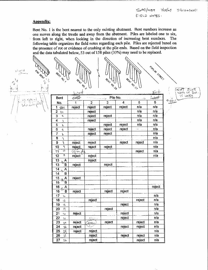

Appendix 2 Trail Creek Pedestrian Bridge
TranSystems Field Photographs

Figure 1: South End of Remaining Trestle Structure
Figure 2: East Elevation of South Approaches

Figure 3: West Elevation of South Approaches
Figure 4: West Elevation of Creek and South Approach Spans

Figure 5: West Elevation of Creek Spans
Figure 6: West Elevation at Dudley Park Access Road

Figure 7: Superstructure View from North Abutment
Figure 8: Steel Superstructure of Three Creek Spans

Figure 9: Steel Superstructure Details
Figure 10: Abutment 1

Figure 11: Bent 2 North Elevation
Figure 12: Bent 3 North Elevation Lower Section

Figure 13: Bent 3 North Elevation Upper Section
Figure 14: Bent 4 North Elevation Lower Section
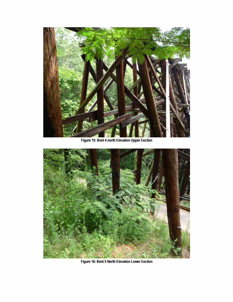
Figure 15: Bent 4 north Elevation Upper Section
Figure 16: Bent 5 North Elevation Lower Section

Figure 17: Bent 5 North Elevation Middle Section
Figure 18: Bent 5 North Elevation Upper Section

Figure 19: Bent 6 South Elevation Lower Section
Figure 20: Bent 6 South Elevation Upper Section
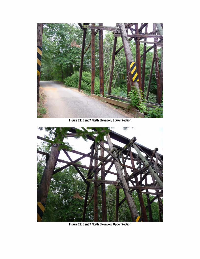
Figure 21: Bent 7 North Elevation, Lower Section
Figure 22: Bent 7 North Elevation, Upper Section

Figure 23: Bent 8 North Elevation Lower Section
Figure 24: Bent 8 North Elevation Upper Section

Figure 25: Bents 10 and 11
Figure 26: Bents 11 and 12

Figure 27: Bent 13 North Elevation Upper Section
Figure 28: Bents 14 and 13 Concrete Footings, East Ends

Figure 29: Bent 15 South Elevation Lower Section
Figure 30: Bent 15 South Elevation Upper Section

Figure 31: Bents 19, 20 and 21 South Elevations Lower Sections
Figure 32: Bents 19, 20 and 21 South Elevations Upper Sections

Figure 33: Bents 23, 24 and 22 South Elevations
Figure 34: Bent 26 South Elevation

Figure 35: Bent 27 South Elevation
Figure 36: Removed Bent Locations North of Poplar Street

Figure 37: Removed Bent Locations and South Abutment South of Poplar Street

Appendix 4 Trail Creek Pedestrian Bridge
Pete Silcox – Photographs and Documentation

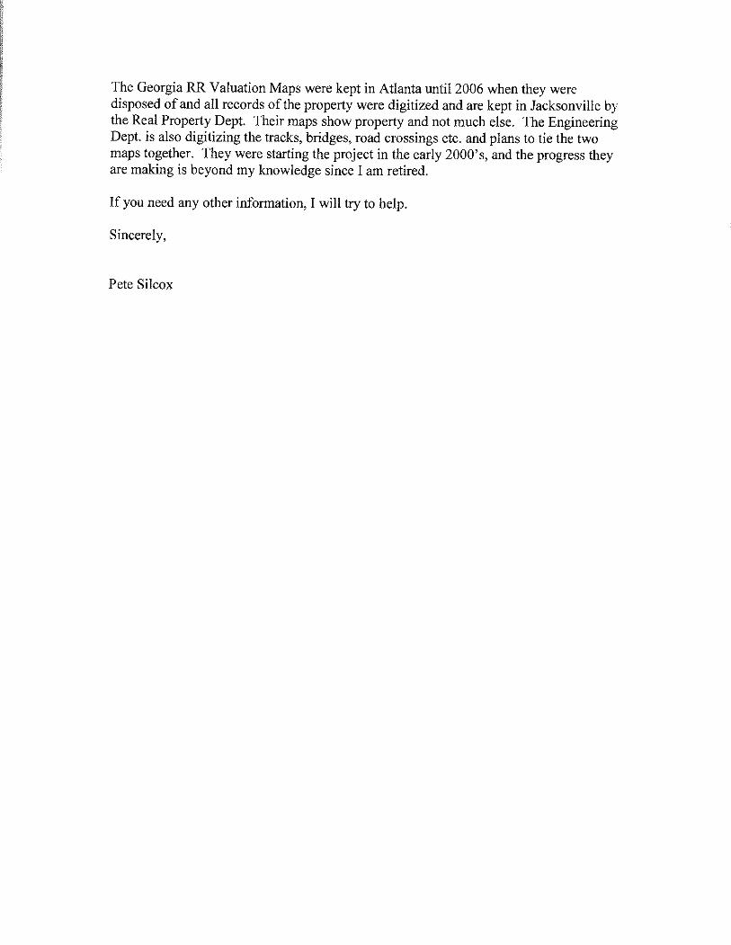

sashaup
Text Box
South end of Trail Creek bridge over Poplar Street


sashaup
Text Box
Peter Street


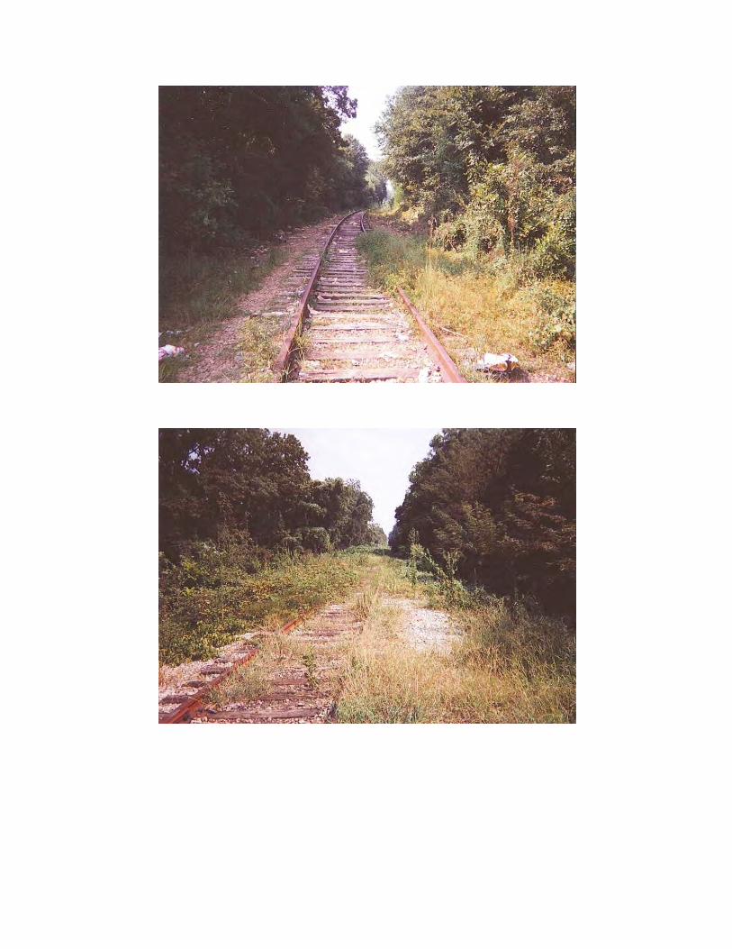


Appendix 5 Trail Creek Pedestrian Bridge
STV/Ralph Whitehead 2008 Inspection Report