Novel viscosity determination method: Validation and ...
29
HAL Id: hal-00641574 https://hal.archives-ouvertes.fr/hal-00641574 Submitted on 17 Nov 2011 HAL is a multi-disciplinary open access archive for the deposit and dissemination of sci- entific research documents, whether they are pub- lished or not. The documents may come from teaching and research institutions in France or abroad, or from public or private research centers. L’archive ouverte pluridisciplinaire HAL, est destinée au dépôt et à la diffusion de documents scientifiques de niveau recherche, publiés ou non, émanant des établissements d’enseignement et de recherche français ou étrangers, des laboratoires publics ou privés. Novel viscosity determination method: Validation and application to fuel flow Nicolas Gascoin, Guillaume Fau, Philippe Gillard To cite this version: Nicolas Gascoin, Guillaume Fau, Philippe Gillard. Novel viscosity determination method: Validation and application to fuel flow. Flow Measurement and Instrumentation, Elsevier, 2011, 22, pp.529-536. 10.1016/j.flowmeasinst.2011.10.002. hal-00641574
-
Upload
khangminh22 -
Category
Documents
-
view
0 -
download
0
Transcript of Novel viscosity determination method: Validation and ...
HAL Id: hal-00641574https://hal.archives-ouvertes.fr/hal-00641574
Submitted on 17 Nov 2011
HAL is a multi-disciplinary open accessarchive for the deposit and dissemination of sci-entific research documents, whether they are pub-lished or not. The documents may come fromteaching and research institutions in France orabroad, or from public or private research centers.
L’archive ouverte pluridisciplinaire HAL, estdestinée au dépôt et à la diffusion de documentsscientifiques de niveau recherche, publiés ou non,émanant des établissements d’enseignement et derecherche français ou étrangers, des laboratoirespublics ou privés.
Novel viscosity determination method: Validation andapplication to fuel flow
Nicolas Gascoin, Guillaume Fau, Philippe Gillard
To cite this version:Nicolas Gascoin, Guillaume Fau, Philippe Gillard. Novel viscosity determination method: Validationand application to fuel flow. Flow Measurement and Instrumentation, Elsevier, 2011, 22, pp.529-536.�10.1016/j.flowmeasinst.2011.10.002�. �hal-00641574�
1/28
Novel Viscosity Determination Method: Validation and Application on Fuel Flow.
N. Gascoina,1
, G. Faua, P. Gillard
a
aPRISME Institute, University of Orléans
63, avenue de Lattre de Tassigny, 18020 Bourges Cedex, France
Abstract
The kinematic viscosity is a major physical property to be used in numerical, experimental and analytical work
in all the related fields of fluid flow research. Its determination can be based on experiments with viscometer and on
calculations for single or multi-species components, possibly through the use of mixture law and other intermediate
parameters. Its experimental estimation for multi-species and/or supercritical hydrocarbon mixtures under high
temperature and pressure remains quite absent. The novel approach proposed in this paper is based on fluid
permeation through characterized porous media. The Darcian law or the Darcy-Forchheimer equation are used
depending on the flow regime. First tests have been realized with pure gaseous nitrogen at ambient then hot
temperature (1200 K) for several varying pressures (up to 60 bar). The accuracy of the methods can be as low as 5
% by comparison to National Institute of Standards and Technology data. The main source of uncertainty is found to
be linked to the characteristics of sensors. The method has been applied to liquid dodecane (from 300 K to 700 K
and up to 60 bar) with the same order of accuracy before testing it on supercritical n-dodecane (658 K to 700 K up
to 60 bar) for which no validation data have been found. By comparisons with computations for multi-species
mixture, even multi-phase, a reasonable agreement is found. The novel viscosity determination technique opens a
new field of fluid characterization in extreme operating conditions.
Keywords
Rheology; Porous media; Fluid flow; Physical properties; Hydrocarbon fuel.
1 Corresponding author. Tel.: +33.248.238.473; fax: +33.248.238.871. E-mail address:
[email protected] (N. Gascoin)
2/28
Nomenclature
KD = Darcian permeability (m²)
KF = Forchheimer's permeability (m)
L = Porous media thickness (m)
m& = Mass flow rate (kg.s-1
)
P = Pressure (Pa)
r = Constant of real gas (J.kg-1
.K-1
)
S = Permeation surface (cross-section of fluid flow) (m²)
T = Temperature (K)
V = Fluid velocity (m.s-1
)
µ = Dynamic Viscosity (Pa.s)
ν = Kinematic Viscosity (m².s-1
)
ρ = Density (kg.m-3
)
in = subscript for inlet conditions
mean = subscript referring to mean value between inlet and outlet conditions
out = subscript for outlet conditions
1. Introduction
The regenerative cooling technique consists in using hydrocarbon fuel as coolant for the thermal management of
hypersonic structures and to take benefits from the endothermicity of its pyrolysis [1], [3]. The complex and coupled
phenomena need to be studied together to ensure the correct understanding of their relationship [4] even if specific
studies dedicated to single phenomena are also required [5]. These latest can be investigated by numerical and
experimental work while their entire coupling is preferably studied with numerical simulation [4]. For both
approaches, the kinematic viscosity is of importance. It is used indirectly to determine other material properties such
as porous media permeability [5] or directly in Computational Fluid Dynamics simulations [4], [6]. This fluid
3/28
property is necessary in almost all the fields related to fluid flow [7]. For this reason, numerous works can be found
in open literature on its numerical and experimental determination.
The exploitation of pressure measures, in case of capillary flow but not only, is known to give access to the
dynamic viscosity [8]- [10]. The experimental methods found for the viscosity determination use rheometer [8],
resonating tubes [7], commercial capillary and falling-body viscometer [9]- [11], optical methods [12]. They are
mainly indirect methods and the kinematic viscosity is often deduced from the dynamic one by using the density [7],
[10], [12]. Nevertheless, most of the studies are related to pure fluid [7], obviously to single phase flow [7], [8] and
to standard conditions. The temperatures are generally lower than the boiling point and pressure around atmosphere
except for petroleum related studies. Indeed, many works are focusing on viscosity determination of oil and heavy
petroleum cuts [8], [13]- [15]. But few results are dedicated to kerosene or hydrocarbons mixtures and only at low
temperature conditions [10], [16]. The pressure effect is more easily observed despite it is of lower importance [17].
The work of Tate et al. must be mentioned for biodiesel [9] because they worked up to 573 K but not more to avoid
pyrolysis and boiling. The one of Teutenberg et al. [18] is also of interest because they proposed viscosity
determination up to 523 K but not for hydrocarbons. Among all of these works, Radovanovic et al. experimentally
measured liquid bio-oil viscosity in case of heating accompanied by gaseous products formation (vaporization and
possible pyrolysis) [19]. The temperature was limited (350 K) and they proposed a way to avoid gas perturbation on
viscosity determination of liquid.
Some specific methods are proposed to determine experimentally the viscosity. The one of Arzate et al. can be
mentioned because it is applied directly onto a process line with online measure but it is not possible to consider
reacting flow [10]. Al-Ghouti et al. [20] propose an interesting technique based on FTIR signal to determine the
Viscosity Index (linked to the viscosity variation under thermal gradient) which could be tested under high
temperature and pressure conditions. The most promising experimental method is presented by Kalotay [21] which
uses a differential pressure sensor coupled to a Coriolis mass flow meter to obtain the dynamic viscosity. Its
technique is similar to the one proposed in the present paper because it used the link between mass flow rate and
pressure loss. It is based on the exploitation of changes in resonance frequency. It is theoretically suitable for all
kind of flows and of operating conditions. However, the main drawback is that its work is purely theoretical and no
validation or tests have been performed. It could be tested, such as the method of Al-Ghouti, for the viscosity
determination of pyrolysed hydrocarbons mixture to observe its adequacy to the present requirements.
4/28
Numerical works are also found to propose analytical formula to estimate the viscosity of pure [11], [15], [22] or
multispecies mixture [23]- [25]. The work of Derevich [26] is interesting to consider hydrocarbon mixtures over a
wide range of operating conditions but he validates his work only up to 500 K because of the lack of experimental
data. Weirong and Lempe [27] studied a large number of species but only with binary mixtures up to 350 K.
Yuan et al. [28] studied numerically and experimentally biodiesel with limited thermal range to 373 K. Xuan et al.
[29] present an extended method for most of the hydrocarbon families, which is of interest to investigate viscosity
variations of pyrolysed fuel over wide range of operating conditions. Nevertheless, again, no validation is provided
and they propose a large review of available data, which clearly shows the lack of experimental data over 373 K.
The present paper aims at proposing a novel measurement method to determine the kinematic viscosity of pure
and multi-species fluids, under single phase or supercritical state. It is based on the relationship of Darcy's law in
porous media between the pressure drop and the mass flow rate measured through a porous media. The extreme
conditions of temperature and pressure are notably focused. The technique is also applicable to multiphase flow by
mean of an "equivalent kinematic viscosity" even if its physical meaning is limited. Validations of the method are
proposed with pure fluid and an application to pyrolysis mixture is presented with numerical comparison.
2. Material and Methods
The experimental bench used to determine pressure drop and related mass flow rate through porous media with
characterized permeability is presented with the cell containing the porous material (More details in [5]). The test
methodology is described and the analytical Darcy's law used to extract the kinematic viscosity is given.
2.1.Experimental permeation bench
A high pressure and high temperature experimental bench has been set up to enable the study of inert and
reactive flows through porous structures. The bench (derived from the one of the COMPARER project [2]) is
composed of a high pressure pump for liquid fuels injection and of a gas injection for tests with N2 for example. The
reactor is heated by an oven and it is composed of a dedicated permeation cell in which the porous media is inserted.
This cell is made of two main parts (High Pressure Chamber –HPC- for the inlet and Low Pressure Chamber –LPC-
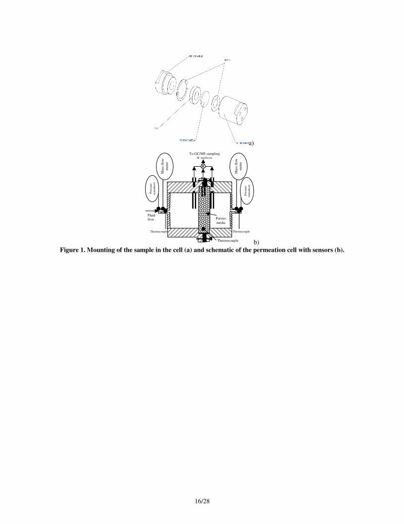
for the outlet) in order to maintain the porous media in the fluid flow and to avoid leakage (Figure 1a). Despite its
small size (external diameter of 40 mm), it enables measuring the temperature, pressure and mass flow rate on each
5/28
side of the porous sample (Figure 1b). Over 20 measures of pressure, mass flow rate and temperature are acquired
transiently during the tests. The temperature is even measured inside the media to get the thermal longitudinal
distribution. Due to limitations on the pressure sensors notably, pressure drops lower than 20 mbars cannot be
measured accurately and this reduces the accuracy of the method. The results to be exploited by means of analytical
formulation (next section), are obtained under stationary or transient conditions with spatial isothermal conditions
(axial and radial thermal gradients are measured to be lower than 20 K) [5]. The inlet pressure is increased
successively up to 60 bar by 2 bar to 10 bar increments for each temperature. The mass flow rate is imposed by the
porous media. Some pyrolysis tests have also been performed with fixed hydraulic conditions with temperature
increase. The pyrolysis products, if any, are analysed by Gas Chromatograph coupled to Mass spectrometer
(GC/MS) and with Fourier Transform Infra Red (FTIR) spectrometer NICOLET 6700 [30].
Figure 1 should be placed here
2.2.Analytical formulations for kinematic viscosity determination
The norm ISO4022 (1987 with update in 2006) proposes a method to determine the permeability of porous
samples. The Darcy-Forchheimer's equation (Eq. 1) is used to link the pressure drop through the porous media to the
fluid velocity. Plotting the term VL
P
..µ
∆ as a function of
µ
ρ V. gives the Darcian term (the origin of the curve). The
angle of climb is related to the Forchheimer's term. The pressure gradient L
P∆ is calculated by Eq. 2. With this
method, the dynamic viscosity, the density and the fluid velocity (Eq. 3 and 4) refer to mean value computed
between the inlet and the outlet of the porous media.
FD K
V
KVL
P
.
.1
.. µ
ρ
µ+=
∆ (1)
L
PP
L
P outin −=
∆ (2)
Tr
PP
Tr
P outinmeanmean
⋅⋅
+==
2.ρ (3)
S
mV
mean
mean⋅
=ρ
& (4)
This method is extensively used to determine permeability terms [5] even if other methods are available for such
measure [31]. Nevertheless, for some metallic and composite materials at least, it has been shown that both Darcian
6/28
and Forchheimer's permeabilities are constant [5]. As a consequence, if a well characterized material is used, the Eq.
1 could be used to determine the kinematic viscosity by assuming the value of permeation terms. In this study, low
mass flow rate only will be considered to avoid considering the Forchheimer's term (the second term of the right
side in Eq. 1 is negligible). The Eq. 1 can be rewritten to express the pressure drop through the porous media as a
function of kinematic viscosity (Eq. 5) after rearrangement of terms, notably using the conservation law. The Eq. 5
is known as the Darcy's law. It can thus be possible to plot the ratio of dynamic viscosity on density as a function of
measured pressure drop and mass flow rate notably (Eq. 6). The geometrical parameters and the Darcy's term are
supposed to be constant. Thus, the kinematic viscosity is obtained as a function of experimental time and even of
temperature if it varies because the ratio L
SKD is independent from thermal effect. This enables conducting
stationary and transient studies.
∆Ρ=
µ
ρ×
L× m
S× K D (5)
×==
mf
L
SK
ρ
µ D
&
∆Ρυ (6)
The use of hydrocarbon fuel, under high temperature conditions, generally produces pyrolysis [5] and this can be
accompanied by coke formation [32] which impacts on the Darcy's term (clogging of the material porosity). Thus,
the results must be carefully analyzed and are not valid if any coking activity is detected during the tests. The
GC/MS and FTIR apparatus are used in this sense notably [30]. If no carbon deposit is produced but only pyrolysis
products, the kinematic viscosity is the one of mean composition which can change within the through flow. Indeed,
due to the use of global law instead of one dimensional equation, the chemical variations cannot be accurately
considered and the mean properties between inlet and outlet are the resulting data of this method. This is also the
case for pure gas flow of single species such as nitrogen. For this reason, the pressure drop should be limited and the
Darcy's term should be as high as possible (but not too much to ensure the Darcy's law is still applicable).
Furthermore, if the fluid is found under two phases, a single viscosity is not physically justified because the two
phases probably filtrates at different speeds notably. This could also be the case with multi-species flow because of
differentiated diffusion notably. Nevertheless, the numerical codes which consider such flows may not take
explicitly both phases into account. Thus, they use mixture laws which are difficult or impossible to validate [2].
Providing a so called "equivalent kinematic viscosity" presents the major advantage to enable validating both
viscosity computation and mixture law efficiency. It can also be noted that the viscosity value of one of the chemical
7/28
component among others cannot be differentiated and extracted from the measurements, at least by using the
proposed approach. This is not seen as a drawback because for a lot of numerical codes, the mean value only is
required [33]. By using analytical apparatus for chemical composition, the viscosity values are linked to the fluid
composition. The present results could serve later as validation data for numerical methods of viscosity
determination.
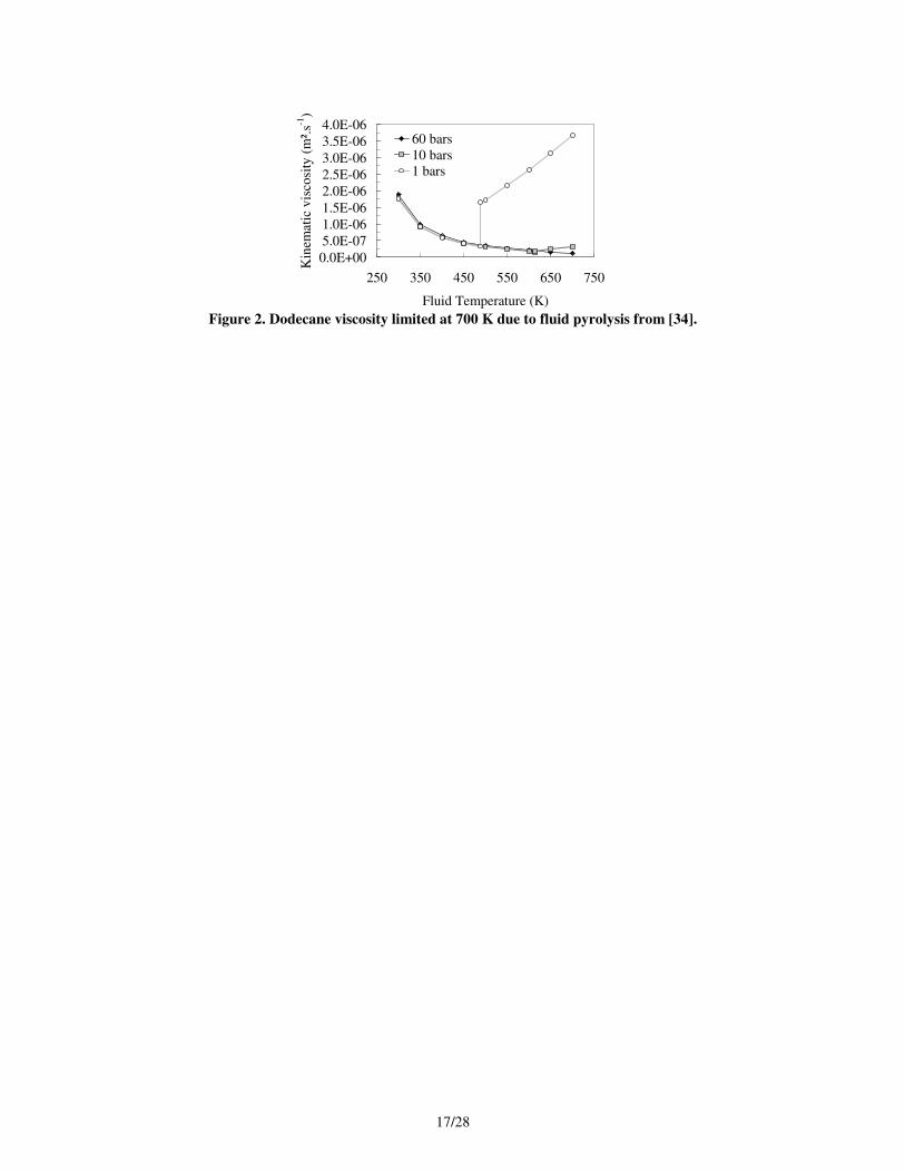
The utility of the proposed method to determine the fluid property is clearly seen when observing the NIST data
(Figure 2). For dodecane (critical coordinates of 658 K, 18 bar), the results are found up to 700 K and not more due
to possible pyrolysis for higher temperature. Furthermore, the supercritical effect is shown to impact the viscosity
because no separation between gas and liquid phase appears at 60 bar (Figure 2). Thus, the range of test conditions
proposed in this paper is quite new and of relevance because no data are available in extreme conditions.
Figure 2 should be placed here
3. Results and discussion
Some permeation data are presented for gaseous nitrogen and liquid n-dodecane flow through SS3 porous media
(Class 3 Poral Stainless Steel sample [5]) under ambient temperature (section 3.1.) to validate the method of
viscosity determination. Then, this latest is applied to same fluids under high temperature and pressure conditions
(section 3.2.). Finally the technique is used on supercritical n-dodecane and multi-species/multiphase flow under
pyrolysis (section 3.3.).
3.1.Validation of the method with N2, CH4 and n-C12H26 at ambient conditions
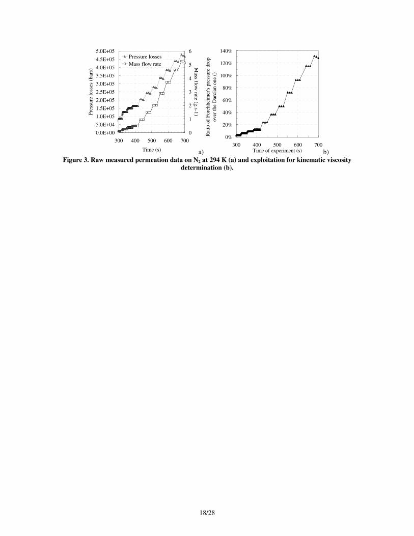
A 2 mm thick SS3 sample is used for N2 flow at 294 K with a Darcian term of 1.82.10-13
m² to limit the pressure
drop inside the porous media (Figure 3a). It reaches a maximum of 4.5 bar for very large mass flow rates (5.5 g.s-1
)
and this is not suitable for the present study because it aims at using the Darcy's law which is mostly appropriate to
low speed flow. When considering the Darcy-Forchheimer's equation (Eq. 1), the two terms of the right side have
been computed for each acquired data point. Their ratio enables to observe (Figure 3b) the relative importance of
each laminar (Darcy) and turbulent (Forchheimer) term. For a ratio of 1 around 620 s, both terms are equivalent.
This shows that a maximum mass flow rate of 0.5 g.s-1
is authorized to ensure that the Forchheimer's term remains
"negligible" (about 16 % the Darcy's one at a time of 400 s). The corresponding pore Reynolds number is 1.2 for this
flow rate. The best would probably be to use even lower mass flow rate but a minimum value is required to keep a
8/28
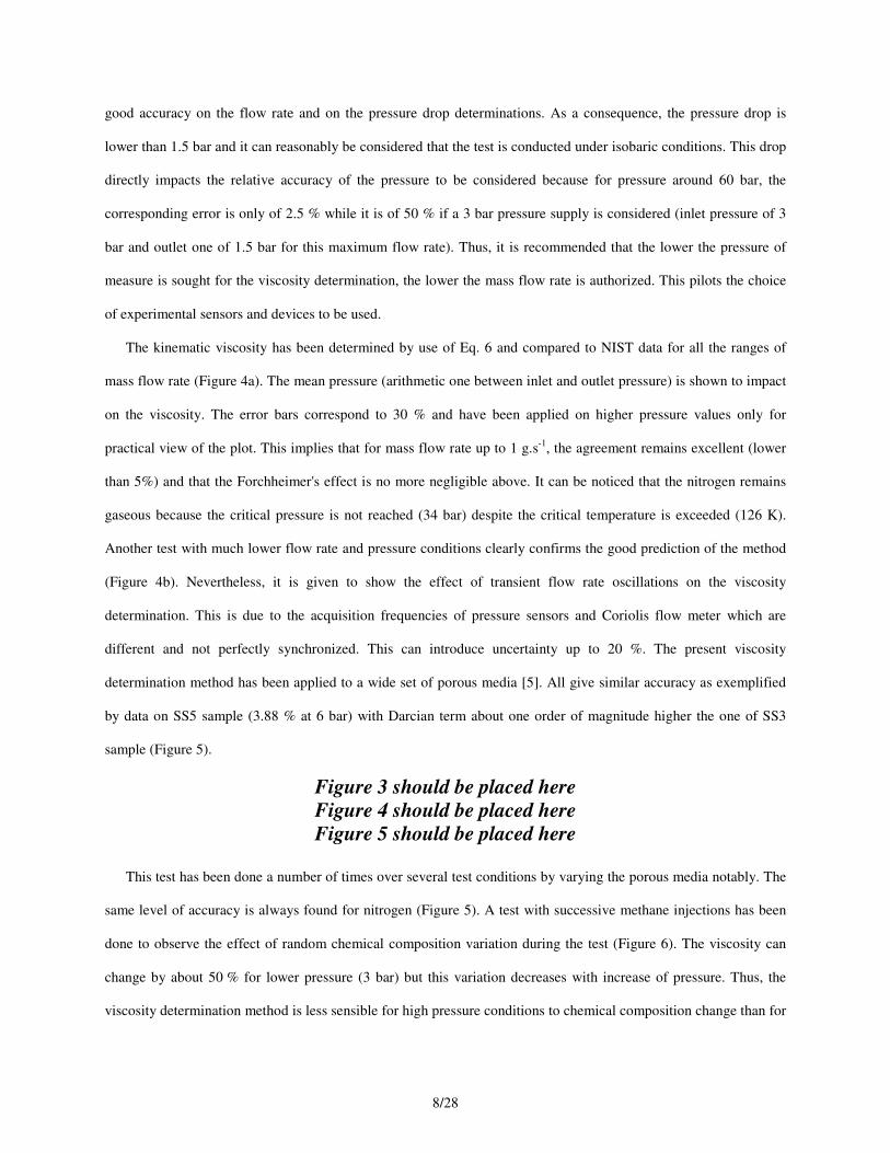
good accuracy on the flow rate and on the pressure drop determinations. As a consequence, the pressure drop is
lower than 1.5 bar and it can reasonably be considered that the test is conducted under isobaric conditions. This drop
directly impacts the relative accuracy of the pressure to be considered because for pressure around 60 bar, the
corresponding error is only of 2.5 % while it is of 50 % if a 3 bar pressure supply is considered (inlet pressure of 3
bar and outlet one of 1.5 bar for this maximum flow rate). Thus, it is recommended that the lower the pressure of
measure is sought for the viscosity determination, the lower the mass flow rate is authorized. This pilots the choice
of experimental sensors and devices to be used.
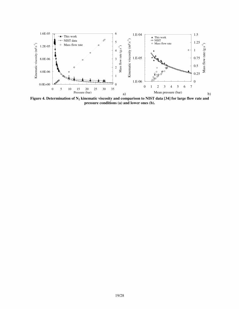
The kinematic viscosity has been determined by use of Eq. 6 and compared to NIST data for all the ranges of
mass flow rate (Figure 4a). The mean pressure (arithmetic one between inlet and outlet pressure) is shown to impact
on the viscosity. The error bars correspond to 30 % and have been applied on higher pressure values only for
practical view of the plot. This implies that for mass flow rate up to 1 g.s-1
, the agreement remains excellent (lower
than 5%) and that the Forchheimer's effect is no more negligible above. It can be noticed that the nitrogen remains
gaseous because the critical pressure is not reached (34 bar) despite the critical temperature is exceeded (126 K).
Another test with much lower flow rate and pressure conditions clearly confirms the good prediction of the method
(Figure 4b). Nevertheless, it is given to show the effect of transient flow rate oscillations on the viscosity
determination. This is due to the acquisition frequencies of pressure sensors and Coriolis flow meter which are
different and not perfectly synchronized. This can introduce uncertainty up to 20 %. The present viscosity
determination method has been applied to a wide set of porous media [5]. All give similar accuracy as exemplified
by data on SS5 sample (3.88 % at 6 bar) with Darcian term about one order of magnitude higher the one of SS3
sample (Figure 5).
Figure 3 should be placed here
Figure 4 should be placed here
Figure 5 should be placed here
This test has been done a number of times over several test conditions by varying the porous media notably. The
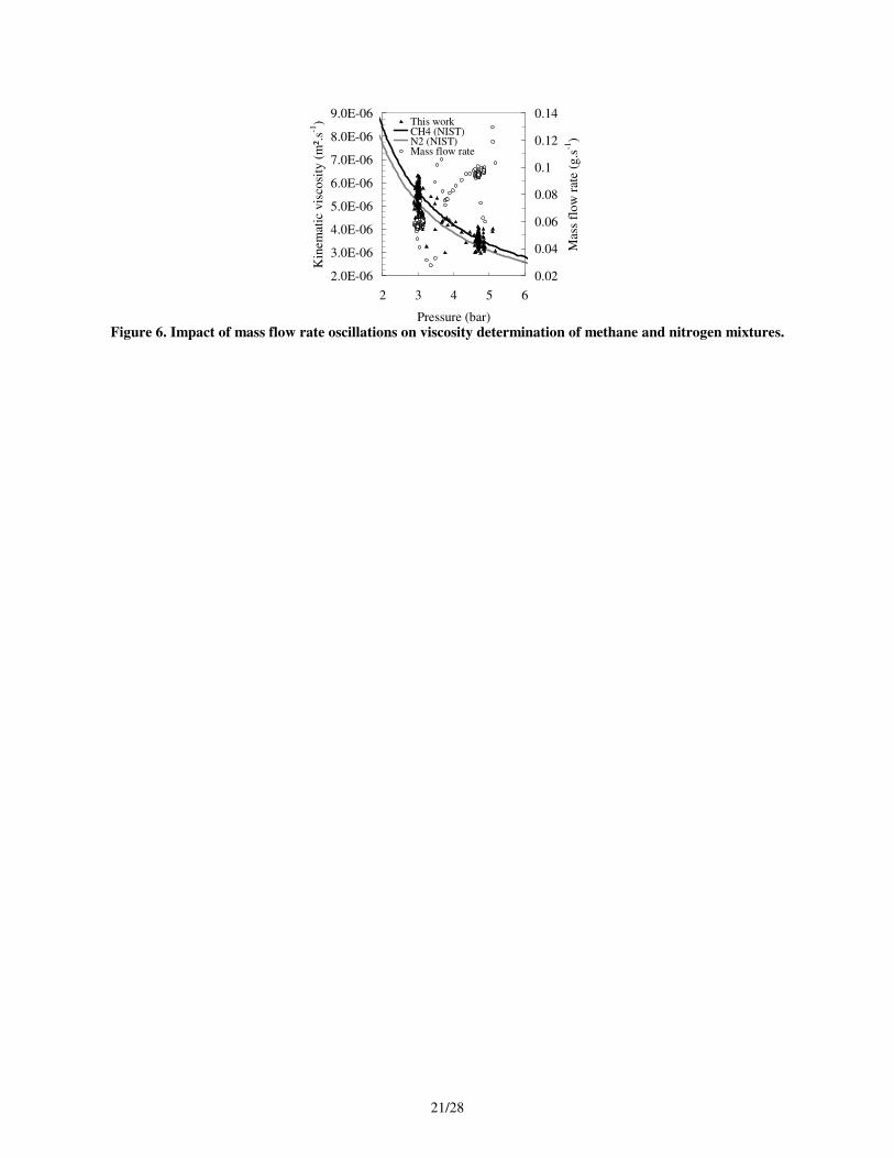
same level of accuracy is always found for nitrogen (Figure 5). A test with successive methane injections has been
done to observe the effect of random chemical composition variation during the test (Figure 6). The viscosity can
change by about 50 % for lower pressure (3 bar) but this variation decreases with increase of pressure. Thus, the
viscosity determination method is less sensible for high pressure conditions to chemical composition change than for
9/28
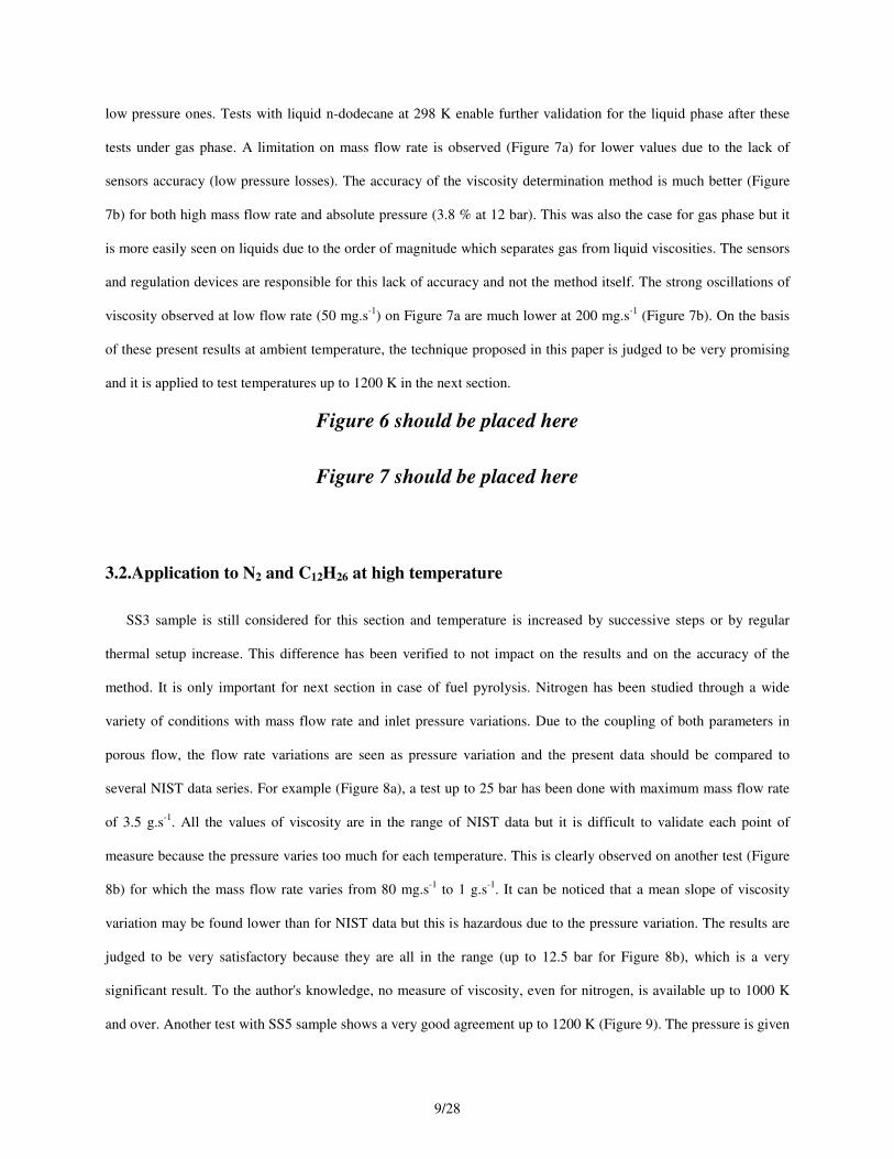
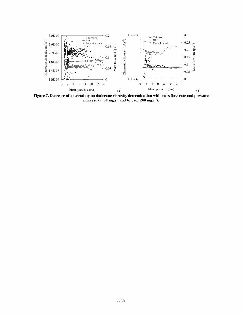
low pressure ones. Tests with liquid n-dodecane at 298 K enable further validation for the liquid phase after these
tests under gas phase. A limitation on mass flow rate is observed (Figure 7a) for lower values due to the lack of
sensors accuracy (low pressure losses). The accuracy of the viscosity determination method is much better (Figure
7b) for both high mass flow rate and absolute pressure (3.8 % at 12 bar). This was also the case for gas phase but it
is more easily seen on liquids due to the order of magnitude which separates gas from liquid viscosities. The sensors
and regulation devices are responsible for this lack of accuracy and not the method itself. The strong oscillations of
viscosity observed at low flow rate (50 mg.s-1
) on Figure 7a are much lower at 200 mg.s-1
(Figure 7b). On the basis
of these present results at ambient temperature, the technique proposed in this paper is judged to be very promising
and it is applied to test temperatures up to 1200 K in the next section.
Figure 6 should be placed here
Figure 7 should be placed here
3.2.Application to N2 and C12H26 at high temperature
SS3 sample is still considered for this section and temperature is increased by successive steps or by regular
thermal setup increase. This difference has been verified to not impact on the results and on the accuracy of the
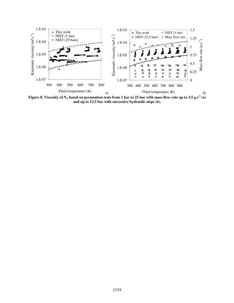
method. It is only important for next section in case of fuel pyrolysis. Nitrogen has been studied through a wide
variety of conditions with mass flow rate and inlet pressure variations. Due to the coupling of both parameters in
porous flow, the flow rate variations are seen as pressure variation and the present data should be compared to
several NIST data series. For example (Figure 8a), a test up to 25 bar has been done with maximum mass flow rate
of 3.5 g.s-1
. All the values of viscosity are in the range of NIST data but it is difficult to validate each point of
measure because the pressure varies too much for each temperature. This is clearly observed on another test (Figure
8b) for which the mass flow rate varies from 80 mg.s-1
to 1 g.s-1
. It can be noticed that a mean slope of viscosity
variation may be found lower than for NIST data but this is hazardous due to the pressure variation. The results are
judged to be very satisfactory because they are all in the range (up to 12.5 bar for Figure 8b), which is a very
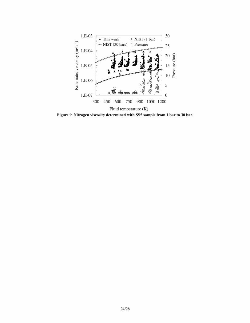
significant result. To the author's knowledge, no measure of viscosity, even for nitrogen, is available up to 1000 K
and over. Another test with SS5 sample shows a very good agreement up to 1200 K (Figure 9). The pressure is given
10/28
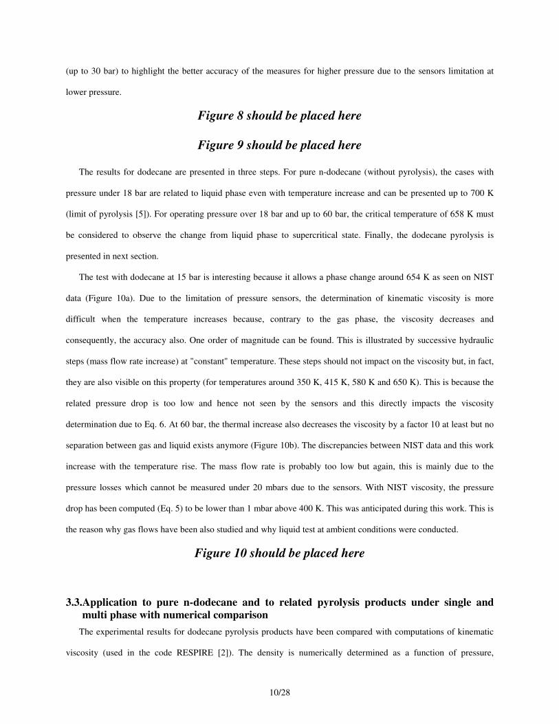
(up to 30 bar) to highlight the better accuracy of the measures for higher pressure due to the sensors limitation at
lower pressure.
Figure 8 should be placed here
Figure 9 should be placed here
The results for dodecane are presented in three steps. For pure n-dodecane (without pyrolysis), the cases with
pressure under 18 bar are related to liquid phase even with temperature increase and can be presented up to 700 K
(limit of pyrolysis [5]). For operating pressure over 18 bar and up to 60 bar, the critical temperature of 658 K must
be considered to observe the change from liquid phase to supercritical state. Finally, the dodecane pyrolysis is
presented in next section.
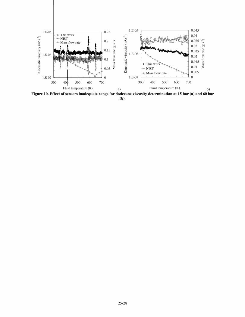
The test with dodecane at 15 bar is interesting because it allows a phase change around 654 K as seen on NIST
data (Figure 10a). Due to the limitation of pressure sensors, the determination of kinematic viscosity is more
difficult when the temperature increases because, contrary to the gas phase, the viscosity decreases and
consequently, the accuracy also. One order of magnitude can be found. This is illustrated by successive hydraulic
steps (mass flow rate increase) at "constant" temperature. These steps should not impact on the viscosity but, in fact,
they are also visible on this property (for temperatures around 350 K, 415 K, 580 K and 650 K). This is because the
related pressure drop is too low and hence not seen by the sensors and this directly impacts the viscosity
determination due to Eq. 6. At 60 bar, the thermal increase also decreases the viscosity by a factor 10 at least but no
separation between gas and liquid exists anymore (Figure 10b). The discrepancies between NIST data and this work
increase with the temperature rise. The mass flow rate is probably too low but again, this is mainly due to the
pressure losses which cannot be measured under 20 mbars due to the sensors. With NIST viscosity, the pressure
drop has been computed (Eq. 5) to be lower than 1 mbar above 400 K. This was anticipated during this work. This is
the reason why gas flows have been also studied and why liquid test at ambient conditions were conducted.
Figure 10 should be placed here
3.3.Application to pure n-dodecane and to related pyrolysis products under single and
multi phase with numerical comparison
The experimental results for dodecane pyrolysis products have been compared with computations of kinematic
viscosity (used in the code RESPIRE [2]). The density is numerically determined as a function of pressure,

11/28
temperature and mixture composition with real gas equation of state considering the Lee-Kesler tables and the Pitzer
acentric factor through the compressibility factor [2], [33]. The dynamic viscosity is obtained [2], [33] by the Guo
method [35] based on Peng Robinson equation. Its accuracy is known to be limited but even a factor 10 on this
property is not dramatic for regenerative cooling application [2]. The Chung method notably is known to be
better [36]. Several mixtures laws are used to give a mean value of multiphase and/or multi-species fluid [2], [33].
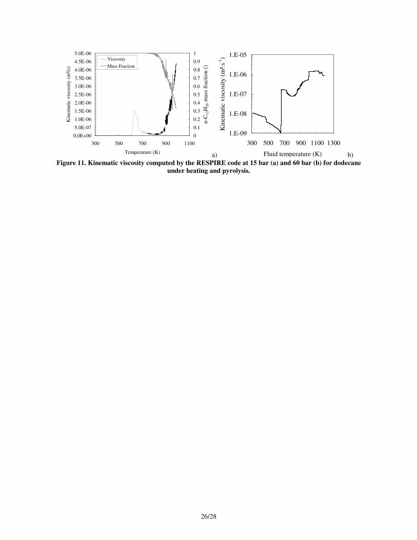
As example of numerical computation, two cases under sub- and supercritical pressure (Figure 11) are given
with the mass fraction of dodecane to observe the viscosity change as a function of temperature and of chemical
composition. These calculations correspond to COMPARER configuration (open SS tubular reactor) and not to
permeation test but they are at least of qualitative interest. The first value of viscosity is given around 620 K (Figure
11a). It decreases when pure dodecane is heated before increasing during the pyrolysis (from 800 K to 1000 K).
Some of the species are liquid and others are gaseous. A numerical mean viscosity is considered even if not physical
but this is compulsory for 1-D simulations. For pressure around 60 bar, all the possible pyrolysis products are
supercritical when the temperature of dodecane decomposition is reached [2]. The viscosity is found to increase with
the temperature but the chemical composition also impacts its value because its variation is not regular (Figure 11b).
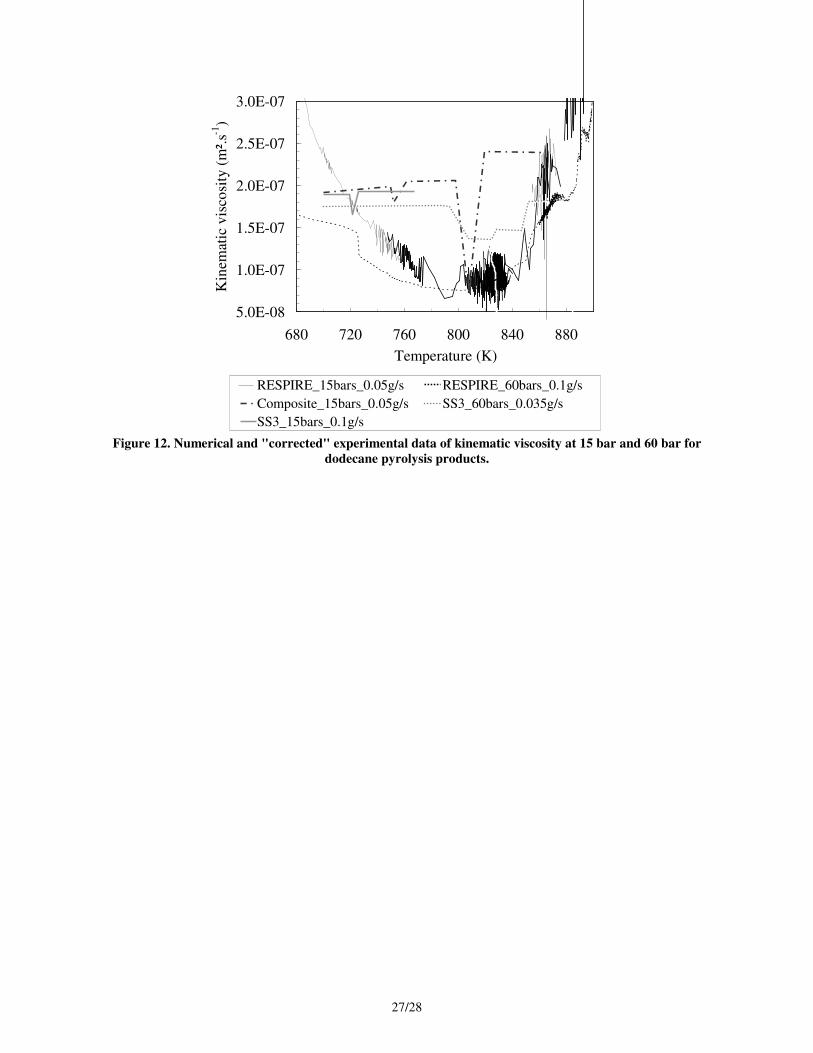
Comparing these numerical results to experimentally determine kinematic viscosity gives very interesting
results. The values are of the same order and a maximum of 50 % is found among the results (Figure 12). All the
curves present a slight decrease and then increase in the range 680 K – 880 K. Due to the difficulty to get such
results and because of their novelty, the agreement is judged to be satisfactory. The determination of the kinematic
viscosity under pyrolysis (if no coking activity is detected) is demonstrated to be possible with adapted pressure
sensors and with specific experimental methodology (constant flow rate and thermal increase would be better).
Figure 11 should be placed here
Figure 12 should be placed here
4. Conclusions
The determination of kinematic viscosity has been proposed with a newly developed method based on the
Darcy's law which provides a relationship between the pressure drop through a porous media and the related mass
flow rate. This formulation can be rearranged to express the viscosity as a function of the ratio of both measures. A
12/28
specific test bench developed for porous media characterization enabled over hundred tests to be performed with
nitrogen, hydrogen, methane, water, dodecane and some of their mixture for temperature up to 1200 K and pressure
up to 60 bar. Single and multi-species flows have been observed under single or multiphase and even at supercritical
state. On the basis of these results, a validation of the method has been proposed with pure nitrogen and dodecane
flow due to the lack of data for other test conditions. The technique has been applied to dodecane under pyrolysis.
Some comparisons to numerical simulation have been provided. For all the cases, the viscosity is at least determined
with the same order of magnitude even if its validation is not possible due to unavailable validation data. The
method is judged to be promising and its accuracy, when possible with other experimental results, is estimated
around 5 % with best stabilized and controlled conditions. Up to 16 % of error can be encountered due to the
omission of Forchheimer's term over 0.5 g.s-1
and this would require treating the flow with Darcy-Forchheimer's
equation instead of Darcian law for high speed flow. Up to 20 % of uncertainty may be observed in case of transient
oscillations in the process because of the steady-state validity of these equations.
As perspectives, the experimental conditions are planned to be better controlled and new sensors should be used
in a future work particularly to enable better precision for high temperature tests with dodecane. It is the only
method to the authors' knowledge to furnish a single value of kinematic viscosity for multi-component mixtures and
to be applicable to high temperature and pressure conditions (even at supercritical state) in comparison to common
viscometers. It presents reliable viscosity values under controlled isothermal and isobaric conditions for monitored
chemical fluid composition. The viscosity is also given in case of multi-phase flow despite its limitation of physical
meaning. This result is particularly interesting to validate the numerical method of viscosity determination and
mixture laws but also to propose for example data tables to be used in numerical codes.
Acknowledgements
This work was supported by the ESA-ESTEC, Contract no.: 3-12861/09/NL/PA. The authors would like to
sincerely thank J Bioud from PRISME, J.Steelant from ESA and M. Bouchez, B Le Naour from MBDA-France for
their help involving this project. The highly valuable work of D. Blanc and D. Courilleau involving the
measurement cell has been greatly appreciated.
References
13/28
[1] Steelant, J., Achievements obtained on Aero-Thermal Loaded Materials forHigh-Speed Atmospheric Vehicles within
ATLLAS, AIAA-2009-7225, 16th AIAA Hypersonic Systems Conference, Bremen, Germany, October 19th-22nd, (2009)
[2] Gascoin, N., Etude et mesure de paramètres pertinents dans un écoulement réactif application au refroidissement par
endo-carburant d'un super-statoréacteur, Editions Universitaires Européennes, avril 2010, ISBN13: 978-6131501074
[3] Bouchez, M., Cheuret, F., Grenard, P., Redford, J.A., Sandham, N.D., Roberts, G.T., Passaro, A., Baccarella, D.,
Dalenbring, M., Smith, J., 2008, Material-Aero-Thermal Interaction Computations in the ATLLAS European Programme, AIAA
paper, 4670.
[4] Gascoin, N., Abraham, G., Gillard, P., 2010, Synthetic and jet fuels pyrolysis for cooling and combustion applications,
J. Anal. Appl. Pyrol., vol. 89, 294-306
[5] Gascoin N., High temperature and pressure reactive flows through porous media, International Journal of Multiphase
Flow, Volume 37, Issue 1, January 2011, 24-35
[6] Bouchez M, Dufour E., Benezech L., Cheuret F., Steelant J., Grenard, P., Redford J. A., Sandham N. D., Roberts G. T.,
Passaro A., Baccarella D., Dalenbring M., Cavagna L., Multi-Level Coupled Simulations of Cooled Structures in the ATLLAS
European Programme, 16th Hypersonic congress, Breme Germany, October 2009, AIAA 2009-7355
[7] Sparks D., Smith R., Cruz V., Tran N., Chimbayo A., Riley D., Najafi N., Dynamic and kinematic viscosity
measurements with a resonating microtube, Sensors and Actuators A 149 (2009) 38–41
[8] Moon D, Migler KB., Measurement of dynamic capillary pressure and viscosity via the multi-sample micro-slit
rheometer, Chemical EngineeringScience 64(2009)4537—4542
[9] Tate R.E., Watts K.C., Allen C.A.W., Wilkie K.I., The viscosities of three biodiesel fuels at temperatures up to 300°C,
Fuel 85 (2006) 1010–1015
[10] Arzate A., Reglat O., Tanguy P.A., Determination of In-line process viscosity using static mixers, Flow Measurement
and Instrumentation 15 (2004) 77–85
[11] Yoshimura M, Boned C, Galliéro G, Bazile J-P, Baylaucq A, Ushiki H, Influence of the chain length on the dynamic
viscosity at high pressure of some 2-alkylamines: Measurements and comparative study of some models, Chemical Physics 369
(2010) 126–137
[12] Garcia Sanchez F., Navas Diaz A., Carnero Ruiz C., Lopez Guerrero M.M., Fluid viscosity determination based on
frequency domain time-resolved fluorescence anisotropy, Journal of Molecular Liquids 155 (2010) 121–126
[13] Boned C., Zéberg-Mikkelsen C.K., Baylaucq A., Daugé P., High-pressure dynamic viscosity and density of two
synthetic hydrocarbon mixtures representative of some heavy petroleum distillation cuts, Fluid Phase Equilibria 212 (2003) 143–
164

14/28
[14] Chang V, Zambrano A, Mena M, Millan A, A sensor for online measurement of the viscosity of non Newtonian fluids
using a neural network approach, Sensors and actuators A, 1995, 332336
[15] Katsoulakis M A., A Representation Formula And Regularizing Properties For Viscosity Solutions Of Second-Order
Fully Nonlinear Degenerate Parabolic Equations, Nonlinear Analysis, Theory, Methods & Applications, Vol. 24, No. 2, pp. 147-
158, 1995.
[16] Moreiras A.F., Garcıa J., Lugo L., Comuñas M.J.P., López E.R., Fernández J., Experimental densities and dynamic
viscosities of organic carbonate + n-alkane or p-xylene systems at 298.15 K, Fluid Phase Equilibria 204 (2003) 233–243
[17] Xuan A, Wu Y, Peng C, Mac P, Correlation of the viscosity of pure liquids at high pressures based on an equation of
state, Fluid Phase Equilibria 240 (2006) 15–21
[18] Teutenberg T., Wiese S., Wagner P., Gmehling J., High-temperature liquid chromatography. Part II: Determination of
the viscosities of binary solvent mixtures—Implications for liquid chromatographic separations, Journal of Chromatography A,
1216 (2009) 8470–8479
[19] Radovanovic M., Venderbosch R.H., Prins W., van Swaaij W.P.M., Some remarks on the viscosity measurement of
pyrolysis Liquids, Biomass and Bioenergy 18 (2000) 209-222
[20] Al-Ghouti M, Al-Degs Y S, Amer M, Application of chemometrics and FTIR for determination of viscosity index and
base number of motor oils, Talanta 81 (2010) 1096–1101
[21] Kalotay P, Density and viscosity monitoring systems using Coriolis ¯ ow meters, ISA Transactions 38 (1999) 303-310
[22] Jones J.C., On the calculation of dynamic viscosities of organic liquids, Fuel 89 (2010) 1746
[23] Gonzalez B, Calvar N, Gomez E, Domınguez A, Density, dynamic viscosity, and derived properties of binary mixtures
of methanol or ethanol with water, ethyl acetate, and methyl acetate at T = (293.15, 298.15, and 303.15) K, J. Chem.
Thermodynamics 39 (2007) 1578–1588
[24] Marcelino Neto M A., Barbosa J R., Solubility, density and viscosity of mixtures of isobutane (R-600a) and a linear
alkylbenzene lubricant oil, Fluid Phase Equilibria 292 (2010) 7–12
[25] Hernandez-Galvan M A., Garcıa-Sanchez F., Macıas-Salinas R, Liquid viscosities of benzene, n-tetradecane, and
benzene + n-tetradecane from 313 to 393K and pressures up to 60MPa: Experiment and modelling, Fluid Phase Equilibria 262
(2007) 51–60
[26] Derevich I.V., Thermodynamic model of viscosity of hydrocarbons and their mixtures, International Journal of Heat
and Mass Transfer 53 (2010) 3823–3830
[27] Weirong JI and Lempe D. A., Calculation of Viscosities of Liquid Mixtures Using Eyring's Theory in Combination
with Cubic Equations of State, Chinese J. Chem. Eng., 14(6) 77C-779 (2006)
15/28
[28] Yuan W., Hansen A.C., Zhang Q., Predicting the temperature dependent viscosity of biodiesel fuels, Fuel 88 (2009)
1120–1126
[29] Xuan A., Wu Y., Peng CW, Ang C and Zhang L, Correlation of Viscosities for Alkane, Aromatic and Alcohol Family
at High Pressure by Modified Tait Equation, Chinese J. Chem. Eng., 14(3) 364-370 (2006)
[30] Abraham G., Etude et développement d’une méthode d’analyse par spectroscopie infrarouge appliquée à la pyrolyse
d’hydrocarbures en conditions supercritiques et transitoires, Ph.D. Thesis, 04/12/2009, University of Orléans, France
[31] Gascoin N., Fau G., Gillard P., Determination of Darcian Permeability of Porous Material by Infrared Spectrometry.,
Journal of Porous Materials, DOI 10.1007/s10934-011-9478-5
[32] Gascoin N., Gillard P., Bernard S., Bouchez M., Characterisation of coking activity during supercritical hydrocarbon
pyrolysis, Fuel Processing and Technology, Vol. 89, Issue 12, December 2008, pp1416-1428.
[33] Gascoin N., Gillard P., Bernard S., Daniau E., Bouchez M., "Pyrolysis of Supercritical Endothermic Fuel: Evaluation
for Active Cooling Instrumentation.", International Journal of Chemical Reactor Engineering, Vol. 6, Article A7, Ed. The
Berkeley Electronic Press, 2008
[34] NIST Webbook, http://webbook.nist.gov
[35] Guo X.Q., Sun CY, Rong SW, Chen GJ, Guo TM, Equation of State Analog Correlations for the Viscosity and Thermal
Conductivity of Hydrocarbons and Reservoir Fluids, J. Petrol Sci Eng, Vol. 30, 2001, 15-27.
[36] Poling B.E., Prausnitz J.M., O'Connell S.P., The properties of Gases and Liquids, Fifth Edition, International Edition,
Mac Graw Hill
16/28
a)
b)
Figure 1. Mounting of the sample in the cell (a) and schematic of the permeation cell with sensors (b).
To GC/MS sampling
& analysis
Porous
media
Mas
s fl
ow
met
er
Mas
s fl
ow
met
er
Pre
ssure
tran
sduce
r
Pre
ssure
tran
sduce
r
Fluid
flow
Thermocouple
Thermocouple
Thermocouple
17/28
0.0E+00
5.0E-07
1.0E-06
1.5E-06
2.0E-06
2.5E-06
3.0E-06
3.5E-06
4.0E-06
250 350 450 550 650 750
Fluid Temperature (K)K
inem
atic
vis
cosi
ty (
m².
s-1)
60 bars
10 bars
1 bars
Figure 2. Dodecane viscosity limited at 700 K due to fluid pyrolysis from [34].
18/28
0.0E+00
5.0E+04
1.0E+05
1.5E+05
2.0E+05
2.5E+05
3.0E+05
3.5E+05
4.0E+05
4.5E+05
5.0E+05
300 400 500 600 700
Time (s)
Pre
ssu
re l
oss
es (
bar
s)
0
1
2
3
4
5
6
Mass flo
w rate (g
.s-1)
Pressure losses
Mass flow rate
a)
0%
20%
40%
60%
80%
100%
120%
140%
300 400 500 600 700Time of experiment (s)
Rat
io o
f F
orc
hh
eim
er's
pre
ssu
re d
rop
over
th
e D
arci
an o
ne
()
b)
Figure 3. Raw measured permeation data on N2 at 294 K (a) and exploitation for kinematic viscosity
determination (b).
19/28
0.0E+00
4.0E-06
8.0E-06
1.2E-05
1.6E-05
0 5 10 15 20 25 30 35Pressure (bar)
Kin
emat
ic v
isco
sity
(m
².s-1
)
0
1
2
3
4
5
6
Mas
s fl
ow
rat
e (g
.s-1
)
This work
NIST data
Mass flow rate
a)
1.E-06
1.E-05
1.E-04
0 1 2 3 4 5 6 7
Mean pressure (bar)
Kin
emat
ic v
isco
sity
(m
².s-1
)
0
0.25
0.5
0.75
1
1.25
1.5
Mas
s fl
ow
rat
e (g
.s-1
)
This workNISTMass flow rate
b)
Figure 4. Determination of N2 kinematic viscosity and comparison to NIST data [34] for large flow rate and
pressure conditions (a) and lower ones (b).

20/28
0.0E+00
3.0E-06
6.0E-06
9.0E-06
1.2E-05
1.5E-05
1.8E-05
0 2 4 6 8 10 12 14
Mean pressure (bar)
Kin
emat
ic v
isco
sity
(m
².s-1
)0
0.25
0.5
0.75
1
1.25
1.5
Mas
s fl
ow
rat
e (g
.s-1
)
This workNISTMass flow rate
Figure 5. N2 viscosity through similar permeation test with SS5 Poral sample.
21/28
2.0E-06
3.0E-06
4.0E-06
5.0E-06
6.0E-06
7.0E-06
8.0E-06
9.0E-06
2 3 4 5 6
Pressure (bar)K
inem
atic
vis
cosi
ty (
m².
s-1)
0.02
0.04
0.06
0.08
0.1
0.12
0.14
Mas
s fl
ow
rat
e (g
.s-1
)
This workCH4 (NIST)N2 (NIST)Mass flow rate
Figure 6. Impact of mass flow rate oscillations on viscosity determination of methane and nitrogen mixtures.
22/28
1.0E-06
1.4E-06
1.8E-06
2.2E-06
2.6E-06
3.0E-06
0 2 4 6 8 10 12 14
Mean pressure (bar)
Kin
em
atic
vis
cosi
ty (
m².
s-1)
0
0.05
0.1
0.15
0.2
Mass
flo
w r
ate
(g.s
-1)
This workNISTMass flow rate
a)
1.0E-06
1.0E-05
0 2 4 6 8 10 12 14
Mean pressure (bar)
Kin
emati
c v
isco
sity
(m
².s-1
)
0
0.05
0.1
0.15
0.2
0.25
0.3
Mas
s fl
ow
rate
(g.s
-1)
This workNISTMass flow rate
b)
Figure 7. Decrease of uncertainty on dodecane viscosity determination with mass flow rate and pressure
increase (a: 50 mg.s-1
and b: over 200 mg.s-1
).
23/28
1.E-07
1.E-06
1.E-05
1.E-04
1.E-03
300 400 500 600 700 800
Fluid temperature (K)
Kin
emat
ic v
isco
sity
(m
².s-1
) This workNIST (1 bar)NIST (25 bars)
a)
1.E-07
1.E-06
1.E-05
1.E-04
1.E-03
300 400 500 600 700 800 900
Fluid temperature (K)
Kin
emat
ic v
isco
sity
(m
².s-1
)
0
0.25
0.5
0.75
1
1.25
1.5
Mas
s fl
ow
rat
e (g
.s-1
)
This work NIST (1 bar)
NIST (12.5 bars) Mass flow rate
b)
Figure 8. Viscosity of N2 based on permeation tests from 1 bar to 25 bar with mass flow rate up to 3.5 g.s-1
(a)
and up to 12.5 bar with successive hydraulic steps (b).
24/28
1.E-07
1.E-06
1.E-05
1.E-04
1.E-03
300 450 600 750 900 1050 1200
Fluid temperature (K)
Kin
emat
ic v
isco
sity
(m
².s-1
)
0
5
10
15
20
25
30
Pre
ssu
re (
bar
)
This work NIST (1 bar)
NIST (30 bars) Pressure
Figure 9. Nitrogen viscosity determined with SS5 sample from 1 bar to 30 bar.
25/28
1.E-07
1.E-06
1.E-05
300 400 500 600 700
Fluid temperature (K)
Kin
em
atic
vis
cosi
ty (
m².
s-1)
0
0.05
0.1
0.15
0.2
0.25
Mas
s fl
ow
rat
e (g
.s-1
)
This workNISTMass flow rate
a)
1.E-07
1.E-06
1.E-05
300 400 500 600 700
Fluid temperature (K)
Kin
emat
ic v
isco
sity
(m
².s-1
)
0
0.005
0.01
0.015
0.02
0.025
0.03
0.035
0.04
0.045
Mas
s fl
ow
rat
e (g
.s-1
)
This work
NIST
Mass flow rate
b)
Figure 10. Effect of sensors inadequate range for dodecane viscosity determination at 15 bar (a) and 60 bar
(b).
26/28
0.0E+00
5.0E-07
1.0E-06
1.5E-06
2.0E-06
2.5E-06
3.0E-06
3.5E-06
4.0E-06
4.5E-06
5.0E-06
300 500 700 900 1100
Temperature (K)
Kin
emat
ic v
isco
sity
(m
²/s)
0
0.1
0.2
0.3
0.4
0.5
0.6
0.7
0.8
0.9
1
n-C
12H
26 m
ass
frac
tion
()
Viscosity
Mass Fraction
a)
1.E-09
1.E-08
1.E-07
1.E-06
1.E-05
300 500 700 900 1100 1300
Fluid temperature (K)
Kin
emat
ic v
isco
sity
(m
².s-1
)
b)
Figure 11. Kinematic viscosity computed by the RESPIRE code at 15 bar (a) and 60 bar (b) for dodecane
under heating and pyrolysis.
27/28
5.0E-08
1.0E-07
1.5E-07
2.0E-07
2.5E-07
3.0E-07
680 720 760 800 840 880
Temperature (K)
Kin
emat
ic v
isco
sity
(m
².s-1
)
RESPIRE_15bars_0.05g/s RESPIRE_60bars_0.1g/s
Composite_15bars_0.05g/s SS3_60bars_0.035g/s
SS3_15bars_0.1g/s
Figure 12. Numerical and "corrected" experimental data of kinematic viscosity at 15 bar and 60 bar for
dodecane pyrolysis products.
28/28
Vitae
• Nicolas Gascoin is associate professor in the University of Orléans (France). He
graduated in 2003 in Mechanical Engineering and he defended his Ph.D. in 2006 in
Process Engineering. He is currently involved in national and European aerospace
projects with the French and European space agencies, with aeronautics companies
(MBDA, Roxel, Nexter) and other academic partners. Thanks to numerical simulation
and experiments, his research activities mainly focus on solid and liquid fuel pyrolysis
and combustion, inert and reactive flow through porous material, chemical kinetic
scheme reduction, surface effect, coke formation.
• Guillaume Fau is assistant engineer since 2009 in the PRISME laboratory of the
University of Orléans (France). He is involved in aerospace propulsion programs with
national and European private and public partners. He handls numerical calculations and
experimental work. His researches focus on fluid permeation through porous composite
materials, on associated fuel pyrolysis, on surface effect determination, on kinetic
mechanism reduction and on flash pyrolysis.
• Philippe Gillard is full professor in the University of Orléans since 1997 (France). He
defended his Ph.D. in 1987 in Process Engineering and he gets his habilitation degree in
1995. He is responsible for 32 researchers in the team Combustion and Explosion of the
PRISME laboratory. He authored or co-authored over 40 peer-review journals and he
supervised 12 Ph.D. Thesis. He is responsible of numerous research contracts with
national and European partners from the industry and the academic community on a wide
range of topics (solid propellants, solid particles combustion, fire hazard and mitigation,
aerospace propulsion).