Novel schemes for local area network emulation in passive optical networks with RF subcarrier...
10
2974 JOURNAL OF LIGHTWAVE TECHNOLOGY, VOL. 23, NO. 10, OCTOBER 2005 Novel Schemes for Local Area Network Emulation in Passive Optical Networks With RF Subcarrier Multiplexed Customer Traffic Nishaanthan Nadarajah, Student Member, IEEE, Manik Attygalle, Member, IEEE, Elaine Wong, Member, IEEE, and Ampalavanapillai Nirmalathas, Senior Member, IEEE Abstract—This paper proposes two novel optical layer schemes for intercommunication between customers in a passive optical network (PON). The proposed schemes use radio frequency (RF) subcarrier multiplexed transmission for intercommunication be- tween customers in conjunction with upstream access to the cen- tral office (CO) at baseband. One scheme employs a narrowband fiber Bragg grating (FBG) placed close to the star coupler in the feeder fiber of the PON, while the other uses an additional short- length distribution fiber from the star coupler to each customer unit for the redirection of customer traffic. In both schemes, only one optical transmitter is required at each optical network unit (ONU) for the transmission of customer traffic and upstream access traffic. Moreover, downstream bandwidth is not consumed by customer traffic unlike in previously reported techniques. The authors experimentally verify the feasibility of both schemes with 1.25 Gb/s upstream baseband transmission to the CO and 155 Mb/s customer data transmission on the RF carrier. The experimental results obtained from both schemes are compared, and the power budgets are calculated to analyze the scalability of each scheme. Further, the proposed schemes were discussed in terms of upgradability of the transmission bit rates for the upstream access traffic, bandwidth requirements at the customer premises, dispersion tolerance, and stability issues for the practical implementations of the network. Index Terms—Fiber Bragg grating, local area network (LAN) intercommunication, passive optical network, subcarrier multi- plexing, time division multiple access. I. I NTRODUCTION T HE PASSIVE optical network (PON) technology has been recognized as an efficient solution to facilitate high- bandwidth, low-cost, and fault-tolerant next-generation broad- band access networks [1], [2]. A typical PON architecture employs either a wavelength-insensitive passive power splitter such as star coupler (SC) or a wavelength-sensitive device such as arrayed waveguide grating (AWG) as a branching device to allow communication between the central office (CO) and the optical network units (ONUs) that are located at the customer premises. The former architecture is referred to as power splitting PON (PS-PON) while the latter architecture is referred to as wavelength division multiplexed PON (WDM- PON) [3]. Customers of a PON may require private communi- Manuscript received December 1, 2004; revised July 15, 2005. The authors are with the National ICT Australia, Victoria Research Labora- tory, Department of Electrical and Electronic Engineering, The University of Melbourne, VIC 3010, Australia (e-mail: [email protected]). Digital Object Identifier 10.1109/JLT.2005.856300 cation links between themselves for various computer applica- tions and telecommunication services such as distributed data processing, broadcast information systems, teleconferencing, and interactive video games. For a PS-PON in which customers share the same upstream wavelength, such intercommunication between customers may be realized by overlaying a separate network in which each ONU is connected to all other ONUs via a point-to-point optical link. This is neither cost effec- tive nor practical. Consequently, there have been increasing interests in deploying point-to-point customer communication links via local area network (LAN) emulation over an existing PON infrastructure. Reuse of the PON infrastructure to facili- tate intercommunication links between customers of the same PON can greatly reduce the cost and management issues of the network. The IEEE 802.3ah Ethernet in the First Mile task force has considered many techniques for LAN emulation in an Ethernet PON [4], [5]. These techniques are mainly focused on higher- layer protocols in which ONUs are assigned PON tags to es- tablish point-to-point connections with each other. LAN traffic, defined in this paper as the customer traffic originating from one customer to be delivered to all or some customers within the same PON, is carried on the upstream wavelength along with the upstream access traffic to the CO. At the CO, the received upstream packets from each customer are routed back to the ONUs in the downstream direction. At the CO, bridges and/or routers are employed to separate the LAN traffic from the up- stream access traffic to CO [4], [5]. These bridges and/or routers must be capable of supporting higher-layer protocols, thereby potentially increasing the cost and complexity of the network. Further, the effective downstream bandwidth is reduced as the LAN traffic is routed back to the ONUs on the downstream wavelength. Moreover, the redirected LAN traffic needs to be separated from the downstream traffic using complex filtering mechanisms that are employed at the ONUs. By comparison, emulating point-to-point links among customers directly on the optical layer in the PON can effectively overcome several drawbacks [6]–[8]. Optical layer LAN emulation techniques have previously been proposed whereby an additional wave- length is used for customer intercommunication [7], [8]. A fiber Bragg grating (FBG) is placed along the feeder fiber close to the star coupler so that the LAN emulation wavelength can be reflected back to all customers. Nonetheless, this necessi- tates an additional optical transceiver capable of transmitting 0733-8724/$20.00 © 2005 IEEE Authorized licensed use limited to: City College of New York. Downloaded on April 14,2010 at 07:25:54 UTC from IEEE Xplore. Restrictions apply.
Transcript of Novel schemes for local area network emulation in passive optical networks with RF subcarrier...

2974 JOURNAL OF LIGHTWAVE TECHNOLOGY, VOL. 23, NO. 10, OCTOBER 2005
Novel Schemes for Local Area Network Emulation inPassive Optical Networks With RF Subcarrier
Multiplexed Customer TrafficNishaanthan Nadarajah, Student Member, IEEE, Manik Attygalle, Member, IEEE, Elaine Wong, Member, IEEE,
and Ampalavanapillai Nirmalathas, Senior Member, IEEE
Abstract—This paper proposes two novel optical layer schemesfor intercommunication between customers in a passive opticalnetwork (PON). The proposed schemes use radio frequency (RF)subcarrier multiplexed transmission for intercommunication be-tween customers in conjunction with upstream access to the cen-tral office (CO) at baseband. One scheme employs a narrowbandfiber Bragg grating (FBG) placed close to the star coupler in thefeeder fiber of the PON, while the other uses an additional short-length distribution fiber from the star coupler to each customerunit for the redirection of customer traffic. In both schemes, onlyone optical transmitter is required at each optical network unit(ONU) for the transmission of customer traffic and upstreamaccess traffic. Moreover, downstream bandwidth is not consumedby customer traffic unlike in previously reported techniques.The authors experimentally verify the feasibility of both schemeswith 1.25 Gb/s upstream baseband transmission to the CO and155 Mb/s customer data transmission on the RF carrier. Theexperimental results obtained from both schemes are compared,and the power budgets are calculated to analyze the scalabilityof each scheme. Further, the proposed schemes were discussedin terms of upgradability of the transmission bit rates for theupstream access traffic, bandwidth requirements at the customerpremises, dispersion tolerance, and stability issues for the practicalimplementations of the network.
Index Terms—Fiber Bragg grating, local area network (LAN)intercommunication, passive optical network, subcarrier multi-plexing, time division multiple access.
I. INTRODUCTION
THE PASSIVE optical network (PON) technology hasbeen recognized as an efficient solution to facilitate high-
bandwidth, low-cost, and fault-tolerant next-generation broad-band access networks [1], [2]. A typical PON architectureemploys either a wavelength-insensitive passive power splittersuch as star coupler (SC) or a wavelength-sensitive devicesuch as arrayed waveguide grating (AWG) as a branchingdevice to allow communication between the central office (CO)and the optical network units (ONUs) that are located at thecustomer premises. The former architecture is referred to aspower splitting PON (PS-PON) while the latter architecture isreferred to as wavelength division multiplexed PON (WDM-PON) [3]. Customers of a PON may require private communi-
Manuscript received December 1, 2004; revised July 15, 2005.The authors are with the National ICT Australia, Victoria Research Labora-
tory, Department of Electrical and Electronic Engineering, The University ofMelbourne, VIC 3010, Australia (e-mail: [email protected]).
Digital Object Identifier 10.1109/JLT.2005.856300
cation links between themselves for various computer applica-tions and telecommunication services such as distributed dataprocessing, broadcast information systems, teleconferencing,and interactive video games. For a PS-PON in which customersshare the same upstream wavelength, such intercommunicationbetween customers may be realized by overlaying a separatenetwork in which each ONU is connected to all other ONUsvia a point-to-point optical link. This is neither cost effec-tive nor practical. Consequently, there have been increasinginterests in deploying point-to-point customer communicationlinks via local area network (LAN) emulation over an existingPON infrastructure. Reuse of the PON infrastructure to facili-tate intercommunication links between customers of the samePON can greatly reduce the cost and management issues ofthe network.
The IEEE 802.3ah Ethernet in the First Mile task force hasconsidered many techniques for LAN emulation in an EthernetPON [4], [5]. These techniques are mainly focused on higher-layer protocols in which ONUs are assigned PON tags to es-tablish point-to-point connections with each other. LAN traffic,defined in this paper as the customer traffic originating from onecustomer to be delivered to all or some customers within thesame PON, is carried on the upstream wavelength along withthe upstream access traffic to the CO. At the CO, the receivedupstream packets from each customer are routed back to theONUs in the downstream direction. At the CO, bridges and/orrouters are employed to separate the LAN traffic from the up-stream access traffic to CO [4], [5]. These bridges and/or routersmust be capable of supporting higher-layer protocols, therebypotentially increasing the cost and complexity of the network.Further, the effective downstream bandwidth is reduced as theLAN traffic is routed back to the ONUs on the downstreamwavelength. Moreover, the redirected LAN traffic needs to beseparated from the downstream traffic using complex filteringmechanisms that are employed at the ONUs. By comparison,emulating point-to-point links among customers directly onthe optical layer in the PON can effectively overcome severaldrawbacks [6]–[8]. Optical layer LAN emulation techniqueshave previously been proposed whereby an additional wave-length is used for customer intercommunication [7], [8]. A fiberBragg grating (FBG) is placed along the feeder fiber close tothe star coupler so that the LAN emulation wavelength canbe reflected back to all customers. Nonetheless, this necessi-tates an additional optical transceiver capable of transmitting
0733-8724/$20.00 © 2005 IEEE
Authorized licensed use limited to: City College of New York. Downloaded on April 14,2010 at 07:25:54 UTC from IEEE Xplore. Restrictions apply.
NADARAJAH et al.: SCHEMES FOR LAN EMULATION IN PONs WITH RF SUBCARRIER MULTIPLEXED TRAFFIC 2975
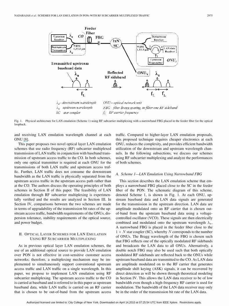
Fig. 1. Physical architecture for LAN emulation (Scheme 1) using RF subcarrier multiplexing with a narrowband FBG placed in the feeder fiber for the opticalloopback.
and receiving LAN emulation wavelength channel at eachONU [8].
This paper proposes two novel optical layer LAN emulationschemes that use radio frequency (RF) subcarrier multiplexedtransmission of LAN traffic in conjunction with baseband trans-mission of upstream access traffic to the CO. In both schemes,only one optical transmitter is required at each ONU for thetransmissions of both LAN traffic and upstream access traf-fic. Further, LAN traffic does not consume the downstreambandwidth as the LAN traffic is physically separated from theupstream access traffic in the upstream access path rather thanat the CO. The authors discuss the operating principles of bothschemes in Section II of this paper. The feasibility of LANemulation through RF subcarrier multiplexing is experimen-tally verified and the results are analyzed in Section III. InSection IV, comparisons between the two schemes are madein terms of upgradability of the transmission bit rates of the up-stream access traffic, bandwidth requirements of the ONUs, dis-persion tolerance, stability requirements of the optical source,and power budget.
II. OPTICAL LAYER SCHEMES FOR LAN EMULATION
USING RF SUBCARRIER MULTIPLEXING
As in previous optical layer LAN emulation schemes, theuse of an additional optical source to provide LAN emulationover PON is not effective in cost-sensitive customer accessnetworks; therefore, a multiplexing mechanism may be im-plemented to simultaneously support conventional upstreamaccess traffic and LAN traffic on a single wavelength. In thispaper, we propose to implement LAN emulation using RFsubcarrier multiplexing. The upstream access traffic to the COis carried at baseband and is referred to in this paper as upstreambaseband data, while LAN traffic is carried on an RF carrierthat is chosen to be out-of-band from the upstream access
traffic. Compared to higher-layer LAN emulation proposals,this proposed technique requires cheaper electronics at eachONU, reduces the complexity, and provides efficient bandwidthutilization of the downstream and upstream wavelength chan-nels. In the following subsections, we discuss our schemesusing RF subcarrier multiplexing and analyze the performancesof both schemes.
A. Scheme 1—LAN Emulation Using Narrowband FBG
This section describes the LAN emulation scheme that em-ploys a narrowband FBG placed close to the SC in the feederfiber of the PON. The schematic diagram of this scheme,denoted Scheme 1, is shown in Fig. 1. At each ONU, up-stream baseband data and LAN data signals are generatedfor the transmission in the upstream direction. LAN data areamplitude modulated onto an RF carrier that is chosen out-of-band from the upstream baseband data using a voltage-controlled oscillator (VCO). These signals are then electricallycombined and modulated onto the upstream wavelength λu.A narrowband FBG is placed in the feeder fiber close to the1 × N star coupler (SC), whereby N corresponds to the numberof ONUs. The Bragg wavelength of the FBG is chosen suchthat FBG reflects one of the optically modulated RF sidebandsand broadcasts the LAN data to all ONUs. Alternatively, adouble notch FBG may also be used such that both opticallymodulated RF sidebands are reflected back to the ONUs whileupstream baseband data are transmitted to the CO. As LAN dataare amplitude modulated on to the RF carrier that generatesamplitude shift keying (ASK) signals, it can be recovered bydirect detection as will be shown through theoretical modelingin Section IV. This allows the LAN data receiver to be of lowbandwidth even though a high-frequency RF carrier is used formodulation. The bandwidth of the LAN data receiver may onlybe in the order of the transmission bit rate of the LAN data.
Authorized licensed use limited to: City College of New York. Downloaded on April 14,2010 at 07:25:54 UTC from IEEE Xplore. Restrictions apply.

2976 JOURNAL OF LIGHTWAVE TECHNOLOGY, VOL. 23, NO. 10, OCTOBER 2005
Fig. 2. LAN emulation architecture (Scheme 2) using RF subcarrier multiplexing with an additional short-length distribution fiber loopback.
Fig. 3. Upstream transmission protocol using TDMA. Upstream baseband data and LAN data are transmitted simultaneously in the preassigned timeslot.
B. Scheme 2—LAN Emulation Using Fiber Loopback
Fig. 2 illustrates the LAN emulation scheme in which theredirection of the optically modulated RF sidebands along withthe upstream baseband data is performed by an (N + 1 ×N + 1) SC and additional short-length distribution fibers. Inthis scheme, denoted as Scheme 2, (N + 1 × N + 1) SC re-places the (1 × N) SC that was used in Scheme 1. The num-ber of ONUs that are attached to the SC is N and one ofthe ports facing towards the ONUs is terminated. Therefore,Scheme 2 requires an additional port in the SC to support thesame number of ONUs as in Scheme 1. Each ONU in the PONis connected to the SC via two short-length distribution fibersas shown in Fig. 2. Signals transmitted from each ONU on λu
are therefore redirected back to each ONU through the seconddistribution fiber. As in Scheme 1, upstream signals consist ofthe baseband data to CO and LAN data that are modulated onan RF carrier to other ONUs. At each ONU, the looped-backsignals are detected and the up-converted RF LAN data areelectrically separated from the upstream baseband data usingan electrical bandpass filter (BPF). Then, the RF LAN data aredown-converted to baseband frequencies using a phase-lockedloop (PLL) containing a VCO to recover the LAN data. Inthis scheme, the modulation of LAN data on the RF carriercould be done in any arbitrary signal format such as ASK,phase shift keying (PSK), or frequency shift keying (FSK) sincecoherent detection of RF signals is performed at the RF LANdata receiver for the recovery of LAN data.
C. Transmission Protocol in the Upstream Direction
In both Schemes 1 and 2, the downstream signal trans-port from the CO to the ONUs is based on time divisionmultiplexing (TDM), whereby the packets in the downstreamdirection are broadcast to all ONUs and each ONU extracts thepackets that are destined to it using the media access control(MAC) address on the packet header. Similarly, the upstreamtransmission of the signals is based on the time division mul-tiple access (TDMA) protocol. As shown in Fig. 3, LAN datamay be concurrently transmitted in the same preassigned timeslot that is used for baseband data transmission to the CO.Likewise, the transmission of baseband data to CO may becarried out even in the absence of LAN data. Similarly, LANdata transmission may be carried out in the absence of upstreambaseband data provided that a time slot is assigned to an ONUfor the transmission by a request by the ONU to the CO forthe LAN data transmission. Using TDMA protocol for thetransmission of signals in the upstream direction reduces therequirement for separate complex protocol for the transmissionof LAN data. In Scheme 2, as both baseband data and RF LANdata are redirected to each ONU through the second distributionfiber, by performing carrier sensing of the redirected signalswith the use of simple and low-cost electronics, carrier sensemultiple access with collision detection (CSMA/CD) protocol,which is an efficient protocol for shorter distribution lengthsand lower transmission rates, can also be adopted [6], [9]. Whilesuch protocol-related issues are important to ensure successful
Authorized licensed use limited to: City College of New York. Downloaded on April 14,2010 at 07:25:54 UTC from IEEE Xplore. Restrictions apply.
NADARAJAH et al.: SCHEMES FOR LAN EMULATION IN PONs WITH RF SUBCARRIER MULTIPLEXED TRAFFIC 2977
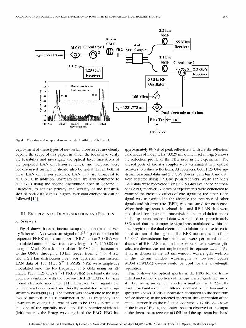
Fig. 4. Experimental setup to demonstrate the feasibility of Scheme 1.
deployment of these types of networks, those issues are clearlybeyond the scope of this paper, in which the focus is to verifythe feasibility and investigate the optical layer limitations ofthe proposed LAN emulation schemes, and therefore werenot discussed further. It should also be noted that in both ofthese LAN emulation schemes, LAN data are broadcast toall ONUs. In addition, upstream data are also redirected toall ONUs using the second distribution fiber in Scheme 2.Therefore, to achieve privacy and security of the transmis-sion of both data signals, higher-layer data encryption can befollowed [10].
III. EXPERIMENTAL DEMONSTRATION AND RESULTS
A. Scheme 1
Fig. 4 shows the experimental setup to demonstrate and ver-ify Scheme 1. A downstream signal of 223-1 pseudorandom bitsequence (PRBS) nonreturn to zero (NRZ) data at 2.5 Gb/s wasmodulated onto the downstream wavelength of λd 1550.08 nmusing a Mach–Zehnder modulator (MZM) and transmittedto the ONUs through a 10-km feeder fiber, a 4 × 4 SC,and a 2.2-km distribution fiber. For upstream transmission,LAN data of 155 Mb/s 223-1 PRBS NRZ were amplitudemodulated onto the RF frequency at 5 GHz using an RFmixer. Then, 1.25 Gb/s 231-1 PRBS NRZ baseband data wereoptically combined with the up-converted RF LAN data usinga dual electrode modulator [11]. However, both signals canbe electrically combined and directly modulated onto the up-stream wavelength [12]. The former was chosen due to the highloss of the available RF combiner at 5-GHz frequency. Theupstream wavelength λu was chosen to be 1551.775 nm suchthat one of the optically modulated RF subcarrier sidebands(left) matches the Bragg wavelength of the FBG. FBG has
approximately 99.7% of peak reflectivity with a 3-dB reflectionbandwidth of 3.625 GHz (0.029 nm). The inset in Fig. 5 showsthe reflection profile of the FBG used in the experiment. Theunused ports of the star coupler were terminated with opticalisolators to reduce reflections. At receivers, both 1.25 Gb/s up-stream baseband data and 2.5 Gb/s downstream baseband datawere detected using 2.5 Gb/s p-i-n receivers, while 155 Mb/sLAN data were recovered using a 2.5 Gb/s avalanche photodi-ode (APD) receiver. A series of experiments were conducted toexamine the crosstalk effects of one signal on the other. Eachsignal was transmitted in the absence and presence of othersignals and bit error rate (BER) was measured for each case.When both upstream baseband data and RF LAN data weremodulated for upstream transmission, the modulation indexof the upstream baseband data was reduced to approximately53% such that the composite signal was modulated within thelinear region of the dual electrode modulator response to avoidthe distortion of the signals. The BER measurements of the2.5 Gb/s downstream baseband data were performed in theabsence of RF LAN data and vice versa since a wavelength-selective device was not implemented to separate λu and λd.If λu is chosen in the 1.3-µm window wavelengths with λd
in the 1.5-µm window wavelengths, a low-cost coarseWDM (CWDM) device could be used for the wavelengthseparation.
Fig. 5 shows the optical spectra at the FBG for the trans-mitted and reflected portions of the upstream signals measuredat FBG using an optical spectrum analyzer with 2.5-GHzresolution bandwidth. The filtered sideband of the transmittedspectrum shows 20-dB suppression compared to the spectrumbefore filtering. In the reflected spectrum, the suppression of theoptical carrier from the reflected sideband is 17 dB. As shownin the inset of Fig. 4, the optical spectra observed at the inputof the downstream receiver at ONU and the upstream baseband
Authorized licensed use limited to: City College of New York. Downloaded on April 14,2010 at 07:25:54 UTC from IEEE Xplore. Restrictions apply.

2978 JOURNAL OF LIGHTWAVE TECHNOLOGY, VOL. 23, NO. 10, OCTOBER 2005
Fig. 5. Observed optical spectra at the narrowband FBG used in the feeder fiber in Scheme 1.
Fig. 6. Measured BER plots for 2.5 Gb/s downstream data, 1.25 Gb/s upstream baseband data, and 155 Mb/s LAN data for Scheme 1.
data receiver at the CO show low crosstalk of the signals thatare due to the backscattered light in the fiber. The crosstalksin the upstream data and downstream data receivers are −23and −25 dB, respectively. Fig. 6 shows the measured BERcurves for the signals. From the BER curves for the LAN data inFig. 6(a), no penalty was observed for the transmission throughthe entire link with and without the upstream baseband data.As the RF LAN data at 5 GHz were placed after the fourthsidelobe of the 1.25 Gb/s upstream baseband data, the inter-ference from the upstream baseband data was negligible. The
penalty for the 1.25 Gb/s upstream baseband data transmissioncompared to back-to-back measurements was 2.1 dB [refer toFig. 6(b)]. This penalty is due to the reduction of the modulationindex as mentioned earlier. The penalty in the presence ofthe downstream signal in the link was also negligible. Asshown in Fig. 6(c), the transmission penalty of 0.15 dB wasmeasured for the 2.5 Gb/s downstream data through the entirelink compared to back-to-back measurements. An additionalpenalty of 0.15 dB was observed in the presence of upstreamsignals. The insets in Fig. 6 show the respective eye patterns for
Authorized licensed use limited to: City College of New York. Downloaded on April 14,2010 at 07:25:54 UTC from IEEE Xplore. Restrictions apply.

NADARAJAH et al.: SCHEMES FOR LAN EMULATION IN PONs WITH RF SUBCARRIER MULTIPLEXED TRAFFIC 2979
Fig. 7. Experimental setup to demonstrate the feasibility of Scheme 2.
the recovered signals and the differences in the shapes are dueto the difference of the low pass filter (LPF) profiles used afterdetection.
B. Scheme 2
The experimental setup to demonstrate the feasibility ofScheme 2 is shown in Fig. 7. The transmission bit rates fordownstream data, upstream baseband data, and LAN data areas in Scheme 1. The downstream signal of 231-1 PRBS NRZdata at 2.5 Gb/s was modulated onto λd = 1550.348 nm andtransmitted to the ONUs. For upstream transmission, 223-1PRBS NRZ binary PSK (BPSK) data at 155 Mb/s were modu-lated onto a 2.5-GHz RF carrier to generate the up-convertedRF LAN data, which were then electrically combined with1.25 Gb/s 231-1 PRBS NRZ data using an RF combiner. InScheme 1, an RF carrier frequency at 5 GHz was used toallow optical filtering. In Scheme 2, as no optical filteringwas employed, a lower RF carrier frequency was used. How-ever, a higher RF carrier frequency could have been used inScheme 2 at the expense of a larger passive loss in the RFpower combiner. The narrowband FBG in Scheme 1 was re-moved for the experimental demonstration of Scheme 2 andan additional 2.2-km distribution fiber was connected to a port(facing the CO) of the SC to the ONU. To avoid crosstalkbetween the combined signals, the up-converted RF signal wasband limited using a BPF with a center frequency of 2.5 GHzand bandwidth of 300 MHz before the combination. Similarly,1.25 Gb/s upstream baseband data were band limited us-ing a 1244 Mb/s synchronous digital hierarchy (SDH) LPF.Thereafter, the composite signals were modulated onto λu =1552.766 nm using a single electrode modulator and transmit-ted in the upstream direction. The upstream wavelength λu inScheme 2 was randomly chosen as it had no restrictions, unlikein Scheme 1, whereby the FBG defined the choice of λu. The
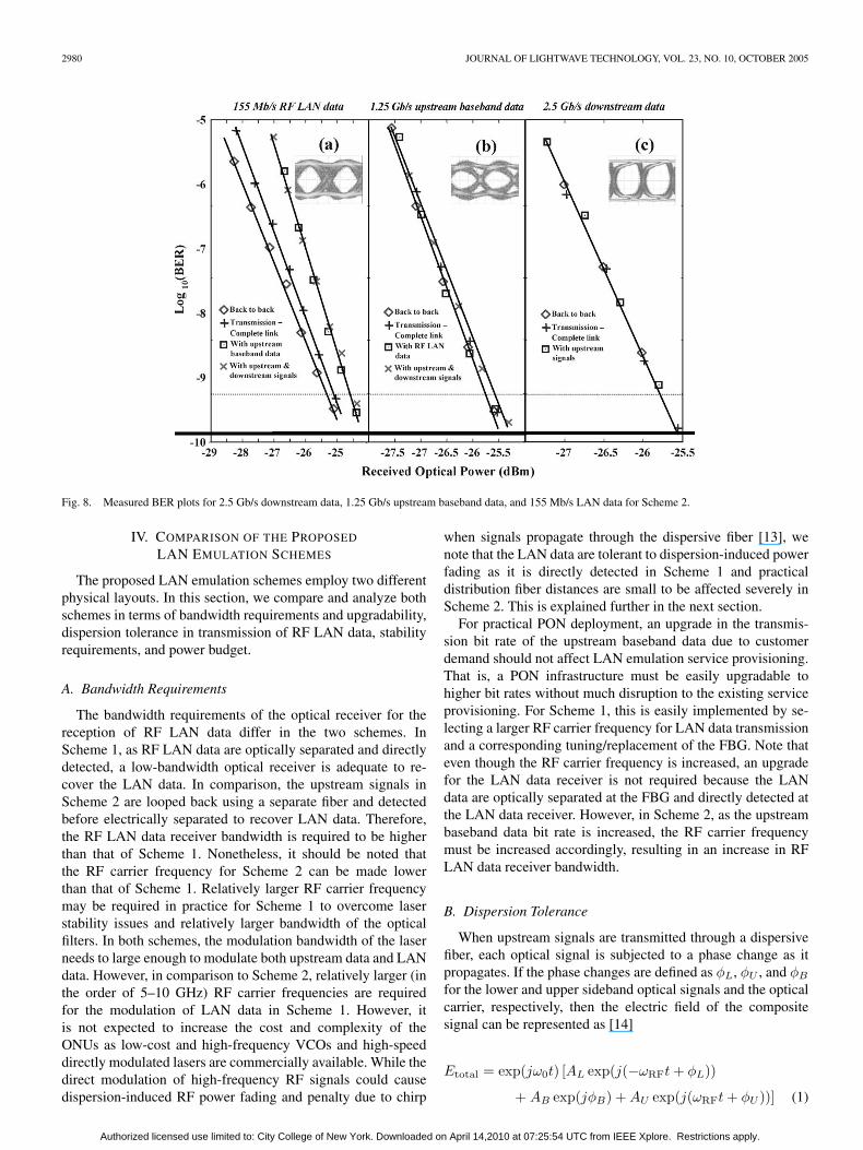
upstream signals are split in the SC whereby one portion istransmitted through the 10-km feeder fiber to the CO whilethe other is redirected back to the ONUs through the seconddistribution fiber. The redirected signals are received at the RFLAN data receiver. The detection of upstream and downstreambaseband signals was performed using the same 2.5 Gb/sp-i-n receivers, while the RF LAN data were detected usingthe 2.5 Gb/s APD receiver. For the recovery of 155 Mb/s LANdata, the detected signals were fed through a BPF centered at2.5 GHz with a bandwidth of 300 MHz and LAN data wererecovered using the PLL based on a Costas loop circuit. Theinset in Fig. 7 shows the crosstalk of the backscattered lightof the downstream and upstream signals at the correspondingreceivers, and they are −22 and −30 dB, respectively. As inScheme 1, each signal was transmitted in the absence andpresence of each other and the crosstalk effects were mea-sured using BER measurements. Fig. 8 shows the measuredBER curves for all signals. Fig. 8(a) shows that the powerpenalty for the 155 Mb/s LAN data compared to back-to-backmeasurements is 0.85 dB. The major cause of this penalty isthe crosstalk from the 1.25 Gb/s upstream baseband data. Thecrosstalk was induced by the nonoptimum operating points inthe MZM leading to nonlinear distortion of the RF LAN data.As shown in Fig. 8(b), the power penalty for 1.25 Gb/s upstreambaseband data is less than 0.1 dB compared to back-to-backmeasurements. In Scheme 2, the power penalty is smallercompared to that of Scheme 1 due to different experimentalimplementations. As the upstream baseband data were electri-cally combined with the up-converted RF da ta, the extinctionratio was reduced due to the loss in the RF combiner and theback-to-back measurements were done while the RF combinerwas in place. Fig. 8(c) shows the BER measurements for the2.5 Gb/s downstream data. No penalty was observed for thetransmission through the link and in the presence of upstreambaseband signals.
Authorized licensed use limited to: City College of New York. Downloaded on April 14,2010 at 07:25:54 UTC from IEEE Xplore. Restrictions apply.
2980 JOURNAL OF LIGHTWAVE TECHNOLOGY, VOL. 23, NO. 10, OCTOBER 2005
Fig. 8. Measured BER plots for 2.5 Gb/s downstream data, 1.25 Gb/s upstream baseband data, and 155 Mb/s LAN data for Scheme 2.
IV. COMPARISON OF THE PROPOSED
LAN EMULATION SCHEMES
The proposed LAN emulation schemes employ two differentphysical layouts. In this section, we compare and analyze bothschemes in terms of bandwidth requirements and upgradability,dispersion tolerance in transmission of RF LAN data, stabilityrequirements, and power budget.
A. Bandwidth Requirements
The bandwidth requirements of the optical receiver for thereception of RF LAN data differ in the two schemes. InScheme 1, as RF LAN data are optically separated and directlydetected, a low-bandwidth optical receiver is adequate to re-cover the LAN data. In comparison, the upstream signals inScheme 2 are looped back using a separate fiber and detectedbefore electrically separated to recover LAN data. Therefore,the RF LAN data receiver bandwidth is required to be higherthan that of Scheme 1. Nonetheless, it should be noted thatthe RF carrier frequency for Scheme 2 can be made lowerthan that of Scheme 1. Relatively larger RF carrier frequencymay be required in practice for Scheme 1 to overcome laserstability issues and relatively larger bandwidth of the opticalfilters. In both schemes, the modulation bandwidth of the laserneeds to large enough to modulate both upstream data and LANdata. However, in comparison to Scheme 2, relatively larger (inthe order of 5–10 GHz) RF carrier frequencies are requiredfor the modulation of LAN data in Scheme 1. However, itis not expected to increase the cost and complexity of theONUs as low-cost and high-frequency VCOs and high-speeddirectly modulated lasers are commercially available. While thedirect modulation of high-frequency RF signals could causedispersion-induced RF power fading and penalty due to chirp
when signals propagate through the dispersive fiber [13], wenote that the LAN data are tolerant to dispersion-induced powerfading as it is directly detected in Scheme 1 and practicaldistribution fiber distances are small to be affected severely inScheme 2. This is explained further in the next section.
For practical PON deployment, an upgrade in the transmis-sion bit rate of the upstream baseband data due to customerdemand should not affect LAN emulation service provisioning.That is, a PON infrastructure must be easily upgradable tohigher bit rates without much disruption to the existing serviceprovisioning. For Scheme 1, this is easily implemented by se-lecting a larger RF carrier frequency for LAN data transmissionand a corresponding tuning/replacement of the FBG. Note thateven though the RF carrier frequency is increased, an upgradefor the LAN data receiver is not required because the LANdata are optically separated at the FBG and directly detected atthe LAN data receiver. However, in Scheme 2, as the upstreambaseband data bit rate is increased, the RF carrier frequencymust be increased accordingly, resulting in an increase in RFLAN data receiver bandwidth.
B. Dispersion Tolerance
When upstream signals are transmitted through a dispersivefiber, each optical signal is subjected to a phase change as itpropagates. If the phase changes are defined as φL, φU , and φB
for the lower and upper sideband optical signals and the opticalcarrier, respectively, then the electric field of the compositesignal can be represented as [14]
Etotal = exp(jω0t) [AL exp(j(−ωRFt + φL))
+ AB exp(jφB) + AU exp(j(ωRFt + φU ))] (1)
Authorized licensed use limited to: City College of New York. Downloaded on April 14,2010 at 07:25:54 UTC from IEEE Xplore. Restrictions apply.
NADARAJAH et al.: SCHEMES FOR LAN EMULATION IN PONs WITH RF SUBCARRIER MULTIPLEXED TRAFFIC 2981
where AL, AU , and AB represent the electrical field amplitudesof the lower and upper sideband optical signals and the opticalcarrier, respectively, and ωRF is the angular frequency of theRF carrier. In Scheme 1, the lower sideband is reflected usingthe narrowband FBG and the reflected field at the RF LAN datareceiver can be expressed as
Ereflected = exp(jω0t) [AL exp(j(−ωRFt + φL))] . (2)
At the RF LAN receiver, the generated photocurrent is given as
ilower =12ρEE∗ =
12ρ|E|2 =
12ρ
[|AL|2]
(3)
where ρ is the responsivity of the photodiode. As can be seenfrom (3), the photocurrent does not depend on ωRF. If a doublenotch FBG is used to reflect only the sidebands, the electricalfield of the reflected optical signal is given as
Ereflected = exp(jω0t) [AL exp(j(−ωRFt + φL))
+ AU exp(j(ωRFt + φU ))] . (4)
Then, the output current of the photodetector is
i =12ρ
[|AL|2 + |AU |2
+ 2Re (ALA∗U ) cos(2ωRFt + φU − φL)] . (5)
As a low-bandwidth optical receiver is used to recover theLAN data, the 2ωRF component falls outside the bandwidthof the photodetector. Moreover, the field amplitudes of thesidebands are the same and can therefore be written as AL =AU = A. In this scenario, (5) can be further modified to be
iboth =12ρ
[|A|2 + |A|2] = ρ[|A|2] = 2 × ilower. (6)
In both implementations of Scheme 1, the photocurrent doesnot depend on ωRF, and since the bandwidth of the LAN data issmall, Scheme 1 is not affected by dispersion induced RF powerfading. From (6), it can be deduced that when both sidebandsare detected, the photocurrent is twice as large as when a singlesideband is detected and therefore the available power marginfor the LAN data increases by approximately 3 dB.
In contrast, the upstream signals are redirected to all ONUsthrough the second distribution fiber in Scheme 2. The receivedRF power of the LAN data can be written as [14]
PRFLANdataα cos2[πLcD
(ωRF
ω0
)2]
(7)
where L is the length of the total transmission distance and Dis the chromatic dispersion of the fiber (= 17 ps/nm/km fora standard single-mode fiber). As shown in (7), the receivedRF signal power depends on the length of the distribution fiberand the RF carrier frequency. Therefore, in Scheme 2, due tothe phase changes in the RF sidebands, dispersion-induced RFfading occurs resulting in power penalty. However, in practice,the length of the employed distribution fibers in the PON isshort as the ONUs are located close (< 2 km) to the SC.
Moreover, the RF carrier frequency for Scheme 2 can be maderelatively low as mentioned earlier. Therefore, the received RFLAN data power does not suffer from significant power penalty.
C. Optical Source Stability
As optical filtering is employed at the FBG to filter out theRF LAN data from the upstream signals in Scheme 1, it neces-sitates tight wavelength control at each ONU. If the wavelengthcontrol is relaxed, wavelength instabilities may lead to crosstalkbetween the upstream baseband data and the RF LAN dataand also distort the filtered signals. This will lead to reducedsensitivity of the LAN data. Scheme 1 also requires that thenarrowband FBG be stable with respect to varying temperatureand environmental effects as it is deployed as part of the outsideplant and therefore a thermal packaging of FBG should be usedin practical implementations. Alternatively, these requirementscan be vastly relaxed if a higher-frequency RF carrier is chosenfor LAN data transmission. This allows the FBG bandwidthto be increased and the stability requirement of the upstreamoptical source to be relaxed. In comparison, Scheme 2 doesnot have such stability requirements due to the removal of thenarrowband FBG in the outside plant of the PON.
D. Power Budget
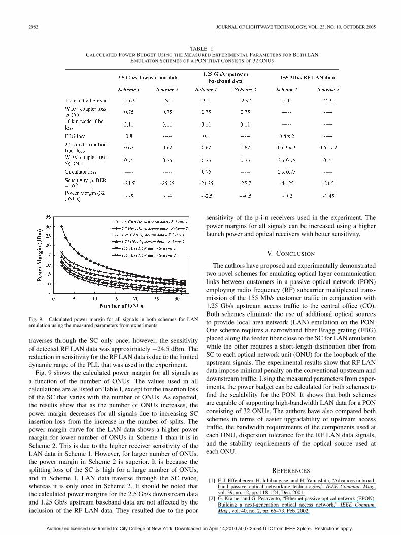
Table I shows the calculated power budget for all signals for aPON consisting of 32 ONUs using the values of the transmittedpower of all signals, the sensitivity and passive loss valuesof the components as measured from the experimental setupsdescribed in Section III; therefore, there are ample marginsfor improvement. The details of both Schemes 1 and 2 areoutlined in Table I. The SC insertion loss is calculated using theformula [15]
Loss = 10 log (2(N − 1)) . (8)
The number of splits is analogous to the number of ONUs inthe PON. The excess loss in the SC is negligible and thereforeignored in the calculations. Referring to Table I, the receiversensitivity for the 2.5 Gb/s downstream data differs with eachscheme. In Scheme 1, a wideband RF amplifier (DC, 5 GHz)was used after the detection of the 2.5 Gb/s downstream data.In Scheme 2, a 2.5-GHz limiting amplifier was used after thedetection of the downstream data. Since the noise bandwidthof 5 GHz is larger than the signal bandwidth of 2.5 GHz inScheme 1, the sensitivity was reduced by approximately1.25 dB. As the modulation depth of the 1.25 Gb/s upstreambaseband data is different in both schemes, the sensitivity inScheme 1 is 1.45 dB lower than that of in Scheme 2. ForScheme 1, 155 Mb/s of LAN data traverses through the starcoupler twice. However, the power margin (0.2 dB) was ade-quate to support higher-bandwidth LAN data for a PON with32 ONUs. This is because of the higher sensitivity of the LANdata at BER = 10−9, which was approximately −44.25 dBm.In Scheme 2, the power margin for the LAN data is sufficientlylarge (1.45 dB) to support a higher-bandwidth LAN data in aPON consisting of 32 ONUs. In this scenario, the RF LAN data
Authorized licensed use limited to: City College of New York. Downloaded on April 14,2010 at 07:25:54 UTC from IEEE Xplore. Restrictions apply.
2982 JOURNAL OF LIGHTWAVE TECHNOLOGY, VOL. 23, NO. 10, OCTOBER 2005
TABLE ICALCULATED POWER BUDGET USING THE MEASURED EXPERIMENTAL PARAMETERS FOR BOTH LAN
EMULATION SCHEMES OF A PON THAT CONSISTS OF 32 ONUS
Fig. 9. Calculated power margin for all signals in both schemes for LANemulation using the measured parameters from experiments.
traverses through the SC only once; however, the sensitivityof detected RF LAN data was approximately −24.5 dBm. Thereduction in sensitivity for the RF LAN data is due to the limiteddynamic range of the PLL that was used in the experiment.
Fig. 9 shows the calculated power margin for all signals asa function of the number of ONUs. The values used in allcalculations are as listed on Table I, except for the insertion lossof the SC that varies with the number of ONUs. As expected,the results show that as the number of ONUs increases, thepower margin decreases for all signals due to increasing SCinsertion loss from the increase in the number of splits. Thepower margin curve for the LAN data shows a higher powermargin for lower number of ONUs in Scheme 1 than it is inScheme 2. This is due to the higher receiver sensitivity of theLAN data in Scheme 1. However, for larger number of ONUs,the power margin in Scheme 2 is superior. It is because thesplitting loss of the SC is high for a large number of ONUs,and in Scheme 1, LAN data traverse through the SC twice,whereas it is only once in Scheme 2. It should be noted thatthe calculated power margins for the 2.5 Gb/s downstream dataand 1.25 Gb/s upstream baseband data are not affected by theinclusion of the RF LAN data. They resulted due to the poor
sensitivity of the p-i-n receivers used in the experiment. Thepower margins for all signals can be increased using a higherlaunch power and optical receivers with better sensitivity.
V. CONCLUSION
The authors have proposed and experimentally demonstratedtwo novel schemes for emulating optical layer communicationlinks between customers in a passive optical network (PON)employing radio frequency (RF) subcarrier multiplexed trans-mission of the 155 Mb/s customer traffic in conjunction with1.25 Gb/s upstream access traffic to the central office (CO).Both schemes eliminate the use of additional optical sourcesto provide local area network (LAN) emulation on the PON.One scheme requires a narrowband fiber Bragg grating (FBG)placed along the feeder fiber close to the SC for LAN emulationwhile the other requires a short-length distribution fiber fromSC to each optical network unit (ONU) for the loopback of theupstream signals. The experimental results show that RF LANdata impose minimal penalty on the conventional upstream anddownstream traffic. Using the measured parameters from exper-iments, the power budget can be calculated for both schemes tofind the scalability for the PON. It shows that both schemesare capable of supporting high-bandwidth LAN data for a PONconsisting of 32 ONUs. The authors have also compared bothschemes in terms of easier upgradability of upstream accesstraffic, the bandwidth requirements of the components used ateach ONU, dispersion tolerance for the RF LAN data signals,and the stability requirements of the optical source used ateach ONU.
REFERENCES
[1] F. J. Effenberger, H. Ichibangase, and H. Yamashita, “Advances in broad-band passive optical networking technologies,” IEEE Commun. Mag.,vol. 39, no. 12, pp. 118–124, Dec. 2001.
[2] G. Kramer and G. Pesavento, “Ethernet passive optical network (EPON):Building a next-generation optical access network,” IEEE Commun.Mag., vol. 40, no. 2, pp. 66–73, Feb. 2002.
Authorized licensed use limited to: City College of New York. Downloaded on April 14,2010 at 07:25:54 UTC from IEEE Xplore. Restrictions apply.
NADARAJAH et al.: SCHEMES FOR LAN EMULATION IN PONs WITH RF SUBCARRIER MULTIPLEXED TRAFFIC 2983
[3] R. D. Feldman, E. E. Harstead, S. Jiang, T. H. Wood, and M. Zirngibl,“An evaluation of architectures incorporating wavelength division multi-plexing for broad-band fiber access,” J. Lightw. Technol., vol. 16, no. 9,pp. 1546–1559, Sep. 1998.
[4] E. J. Hernandez-Valencia, “Architectures for broadband residential IPservices over CATV networks,” IEEE Network, vol. 11, no. 1, pp. 36–43,Jan.–Feb. 1997.
[5] G. Kramer, B. Mukherjee, and A. Maislos, “Ethernet passive opticalnetworks,” in IP Over WDM: Building the Next Generation OpticalInternet, S. Dixit, Ed. New York: Wiley, 2003, ch. 8, pp. 229–275.
[6] E. Wong and C.-J. Chae, “CSMA/CD-based ethernet passive opticalnetwork with optical internetworking capability among users,” IEEEPhoton. Technol. Lett., vol. 16, no. 9, pp. 2195–2197, Sep. 2004.
[7] C.-J. Chae, P. Heesang, and E. Jong-Hoon, “An ATM PON system over-laid with a 155-Mb/s optical star network for customer networking andfiber to the premises,” IEEE Photon. Technol. Lett., vol. 13, no. 10,pp. 1133–1135, Oct. 2001.
[8] C.-J. Chae, L. Seung-Tak, K. Geun-Young, and P. Heesang, “A PONsystem suitable for internetworking optical network units using a fiberBragg grating on the feeder fiber,” IEEE Photon. Technol. Lett., vol. 11,no. 12, pp. 1686–1688, Dec. 1999.
[9] C.-J. Chae, E. Wong, and R. S. Tucker, “Optical CSMA/CD media accessscheme for Ethernet over passive optical network,” IEEE Photon. Tech-nol. Lett., vol. 14, no. 5, pp. 711–713, May 2002.
[10] S. S. Roh and S.-H. Kim, “Security model and authentication protocol inEPON-based optical access network,” in Proc. 5th Int. Conf. TransparentOptical Networks, Warsaw, Poland, 2003, pp. 99–102.
[11] D. J. Blumenthal, J. Laskar, R. Gaudino, S. Han, M. D. Shell, andM. D. Vaughn, “Fiber-optic links supporting baseband data andsubcarrier-multiplexed control channels and the impact of MMIC pho-tonic/microwave interfaces,” IEEE Trans. Microw. Theory Tech., vol. 45,no. 8, pp. 1443–1452, Aug. 1997.
[12] A. Kaszubowska, P. Anandarajah, and L. P. Barry, “Multifunctional op-eration of a fiber Bragg grating in a WDM/SCM radio over fiber distrib-ution system,” IEEE Photon. Technol. Lett., vol. 16, no. 2, pp. 605–607,Feb. 2004.
[13] C. Lim, D. Novak, A. Nirmalathas, and G. H. Smith, “Dispersion-inducedpower penalties in millimeter-wave signal transmission using multisectionDBR semiconductor laser,” IEEE Trans. Microw. Theory Tech., vol. 49,no. 2, pp. 288–296, Feb. 2001.
[14] Z. Zhu, V. J. Hernandez, M. Y. Jeon, J. Cao, Z. Pan, and S. J. B. Yoo,“RF photonics signal processing in subcarrier multiplexed optical-labelswitching communication systems,” J. Lightw. Technol., vol. 21, no. 12,pp. 3155–3166, Dec. 2003.
[15] D. Podwika, D. Stefanski, J. S. Witkowski, and E. M. Pawlik, “Computernetworks based on optical passive couplers,” in Proc. 2nd Int. Conf.Transparent Optical Networks, Gdansk, Poland, 2000, pp. 123–126.
Nishaanthan Nadarajah (S’02) received the B.E.degree (with first class honors) in telecommuni-cations engineering from RMIT University, Mel-bourne, Australia, in 2001. He is currently workingtoward the Ph.D. degree in electrical and electronicsengineering at the National ICT Australia Victo-ria Research Laboratory, University of Melbourne,Melbourne, Australia.
His main research interests include optical accessnetworks, photonic packet switching, and opticallabel switching.
Manik Attygalle (S’99–M’02) received the B.E.(with first class honors) and Ph.D. degrees in electri-cal and electronic engineering from the University ofMelbourne, Melbourne, Australia, in 1997 and 2002,respectively.
In 2002, he joined the Photonics Research Labora-tory (PRL), Department of Electrical and ElectronicEngineering, University of Melbourne, as a ResearchFellow. His research interests include fiber-radio net-works, all-optical signal processing, applications ofmode-locked lasers and fiber Bragg gratings, and
long-haul optical link design and optimization.
Elaine Wong (S’99–M’02) received the B.E. (withfirst class honors) and Ph.D. degrees in electricaland electronic engineering from the University ofMelbourne, Melbourne, Australia, in 1998 and 2002,respectively. Her Ph.D. dissertation was on the topicof collision avoidance in all-optical wavelength divi-sion multiplexing (WDM) packet networks.
Since the completion of her Ph.D. degree, she hascontinued work as a Research Fellow at the Pho-tonics Research Laboratory (PRL) and as a memberof the Australian Photonics Cooperative Research
Centre (APCRC) at the University of Melbourne. Her current research interestsinclude optical signal monitoring technologies, photonic packet switchingtechnologies, and applications of multiple access protocols and architecturesfor wavelength division multiplexed networks.
Dr. Wong is a Member of the IEEE Lasers and Electro-Optics Society andIEEE Communications Society. Apart from presenting her research work at anumber of leading international conferences, she is also a recipient of the IEEELaser and Electro-Optic Society (LEOS) Graduate Student Fellowship in 2001and the Best Paper Award from the IEEE Australian Council in 2002.
Ampalavanapillai (Thas) Nirmalathas (S’96–M’97–SM’03) received B.E. (Hons.) degree in elec-trical and electronic engineering and the Ph.D.degree in electrical and electronic engineering fromthe University of Melbourne, Melbourne, Australia,in 1993 and 1997, respectively.
He is an Associate Professor and Reader at theDepartment of Electrical and Electronic Engineer-ing, University of Melbourne, Australia. In 1997,he joined the Photonics Research Laboratory (PRL)at the University of Melbourne where he held the
positions of Research Fellow, Senior Research Fellow, and Senior Lecturerbefore moving to his current position as Associate Professor and Reader. Healso held other positions such as the Director of PRL and the Program Managerof the Telecommunications Technologies Research Program in the AustralianPhotonics Cooperative Research Centre (APCRC) during the period between2001 and 2004. In 2004, he was a Guest Researcher of the Ultra-Fast PhotonicNetwork Group of the National Institute of Information and CommunicationTechnology (NICT), Koganei, Japan, and a Visiting Scientist at the LightwaveDepartment of the Institute for Infocom Research (I2R), Singapore. He iscurrently a contributing Staff Member at the National ICT Australia (NICTA)and the Program Leader for the Network Technologies Program of NICTA.His current research interests include fiber-wireless networks, optical accessnetworks, optical signal monitoring, photonic packet switching technologies,ultrafast optical communications systems, and applications of mode-lockedsemiconductor lasers. He has written more than 130 technical papers in hisfield and has given a number of invited presentations at leading internationalconferences. He also holds two international and one provisional patent.
Dr. Nirmalathas is one of the IEEE Lasers and Electro-Optics Society’s rep-resentatives on the Steering Committee of the CLEO Pacific Rim Conferenceand a member of the Steering Committee of the international Conference onOptical Internet (COIN). He has been a member of committees associated witha number of international conferences in his field of expertise.
Authorized licensed use limited to: City College of New York. Downloaded on April 14,2010 at 07:25:54 UTC from IEEE Xplore. Restrictions apply.