
Software Simulation and Emulation of Automotive Proton Exchange Membrane Fuel Cell System
6
Software Simulation and Emulation of Automotive Proton Exchange Membrane Fuel Cell System D. Rezzak and N. Boudjerda University of Jijel, LAMEL Laboratory Jijel, Algeria d-rezzak@hotmail fr, n_boudjerda@yahoo fr F. Khoucha Polytechnic Military Academy of Algiers, Algiers, Algeria [email protected] Abstract—Fuel cell power generation technology is gaining importance on its own way as it has many advantages like less environmental pollution, high efficiency, cleanliness and safe operation with the present global scenario of electricity generation, distribution and meeting the consumer demand. Several research works have been done in this area of power generation. In this paper, a dynamic model of a Proton Exchange Membrane (PEM) Fuel Cell (FC) has been developed and the dynamic behavior is studied. PEMFC has been chosen due to its low operating temperature and little start-up time that are suitable for stationary applications like residential and transportation uses. This model is used to simulate and emulate dynamic behavior of FC System (FCS) by using a DC– DC converter, the FC Emulator (FCE) must be able to reproduce the nonlinear output voltage – current (V-I) characteristic of a real FC considering auxiliaries devices. Keywords-Fuel cell; dynamic modeling, emulator, power converter I. INTRODUCTION Fuel cell stack systems are under intensive development for mobile and stationary power applications [1]. In particular, Proton Exchange Membrane (PEM) Fuel Cells (also known as Polymer Electrolyte Membrane Fuel Cells) are currently in a relatively more mature stage for automotive applications [1]. The fuel cell is an open reactor where hydrogen (or reformed gas) and oxygen (or air) are fed at the inlet of the fuel cell stack depending on the electrical needs, and the by- product is evacuated at the outlet of the stack. The heat generated from the entropy variation during the electro- chemical reaction and the associated irreversible heat sources is also evacuated by a cooling system. In some conditions, the inlet gas should be heated and/or humidified before entering the stack, which requires recovery of water and heat from the outlet of the fuel cell stack. All these requirements are achieved by devices called fuel cell auxiliaries. These auxiliaries are one of the power factors for the efficiency and the durability of a fuel cell system [2]. The auxiliaries design and the control strategies should be adapted to the fuel cell stack operation characteristics and, also validated by tests performed with the fuel cell stack [2]. Even though, there are important needs of a real fuel cell stack for fuel cell system auxiliaries performance tests and validations, the utilization of a fuel cell stack in such a system validation process still impose some drawbacks: the cost of the tests are expensive (e.g., hydrogen consumption), the lifetime of a fuel cell stack is still limited, the fuel cell stack can be damaged during the tests if the auxiliaries are not well designed, and so on [2]. A possible way to reproduce the behavior of a renewable source, whose electrical characteristic (V-I) is nonlinear (as in the case of a Fuel Cell), is to use a DC/DC converter to provide a realistic V-I output characteristic and electrical transient dynamics. All these considerations suggest that any renewable source should be replaced by a hardware system capable of copying its behavior accurately. This hardware system is called emulator. The advantages of using a fuel cell stack emulator to test auxiliaries are obvious: the emulated fuel cell stack power can be configured to different values using the same emulator, depending on the specified fuel cell stack to be emulated; the limit operating scenarios, such as stack short circuits, stack overheats, can be emulated during the tests without damaging a real fuel cell stack [2], [3]. In this paper we are interested to the simulation and the emulation a PEM Fuel Cell (PEMFC). First, we present a model of the fuel cell system taking into account the auxiliary components such as compressor, humidifier, valve, supply and return manifolds. Based on this model, a simulation of the PEMFC shows that the oxygen excess ratio needs a regulation at an optimal value. This has been performed by means of a simple Proportional-Integral (PI) controller. After, the entire model of the FC system including the FC stack and its auxiliaries, as well as the control system of the dc–dc converter, has been implemented on the DSP320F2812 board in the laboratory and the results compared to the simulations. Finally we give a conclusion in which the results and further works are discussed. II. FUEL CELL MODEL SYSTEM The fuel cell system used in this study is based on the control oriented model explained in [4],[5] which is developed based on physical mass and energy conservations along with electrochemical, thermodynamic and fluid flow principles. A simplified scheme of the system is given in Fig.1. Proceedings of The first International Conference on Nanoelectronics, Communications and Renewable Energy 2013 139 ICNCRE ’13 ISBN : 978-81-925233-8-5 www.edlib.asdf.res.in Downloaded from www.edlib.asdf.res.in
Transcript of Software Simulation and Emulation of Automotive Proton Exchange Membrane Fuel Cell System

Software Simulation and Emulation of Automotive
Proton Exchange Membrane Fuel Cell System
D. Rezzak and N. Boudjerda
University of Jijel, LAMEL Laboratory
Jijel, Algeria
d-rezzak@hotmail fr, n_boudjerda@yahoo fr
F. Khoucha
Polytechnic Military Academy of Algiers,
Algiers, Algeria
Abstract—Fuel cell power generation technology is gaining
importance on its own way as it has many advantages like less
environmental pollution, high efficiency, cleanliness and safe
operation with the present global scenario of electricity generation,
distribution and meeting the consumer demand. Several research
works have been done in this area of power generation. In this paper,
a dynamic model of a Proton Exchange Membrane (PEM) Fuel Cell
(FC) has been developed and the dynamic behavior is studied.
PEMFC has been chosen due to its low operating temperature and
little start-up time that are suitable for stationary applications like
residential and transportation uses. This model is used to simulate
and emulate dynamic behavior of FC System (FCS) by using a DC–
DC converter, the FC Emulator (FCE) must be able to reproduce the
nonlinear output voltage – current (V-I) characteristic of a real FC
considering auxiliaries devices.
Keywords-Fuel cell; dynamic modeling, emulator, power
converter
I. INTRODUCTION
Fuel cell stack systems are under intensive development for mobile and stationary power applications [1]. In particular, Proton Exchange Membrane (PEM) Fuel Cells (also known as Polymer Electrolyte Membrane Fuel Cells) are currently in a relatively more mature stage for automotive applications [1].
The fuel cell is an open reactor where hydrogen (or reformed gas) and oxygen (or air) are fed at the inlet of the fuel cell stack depending on the electrical needs, and the by-product is evacuated at the outlet of the stack. The heat generated from the entropy variation during the electro-chemical reaction and the associated irreversible heat sources is also evacuated by a cooling system. In some conditions, the inlet gas should be heated and/or humidified before entering the stack, which requires recovery of water and heat from the outlet of the fuel cell stack. All these requirements are achieved by devices called fuel cell auxiliaries. These auxiliaries are one of the power factors for the efficiency and the durability of a fuel cell system [2]. The auxiliaries design and the control strategies should be adapted to the fuel cell stack operation characteristics and, also validated by tests performed with the fuel cell stack [2].
Even though, there are important needs of a real fuel cell
stack for fuel cell system auxiliaries performance tests and validations, the utilization of a fuel cell stack in such a system validation process still impose some drawbacks: the cost of the tests are expensive (e.g., hydrogen consumption), the lifetime of a fuel cell stack is still limited, the fuel cell stack can be damaged during the tests if the auxiliaries are not well designed, and so on [2]. A possible way to reproduce the behavior of a renewable source, whose electrical characteristic (V-I) is nonlinear (as in the case of a Fuel Cell), is to use a DC/DC converter to provide a realistic V-I output characteristic and electrical transient dynamics. All these considerations suggest that any renewable source should be replaced by a hardware system capable of copying its behavior accurately. This hardware system is called emulator. The advantages of using a fuel cell stack emulator to test auxiliaries are obvious: the emulated fuel cell stack power can be configured to different values using the same emulator, depending on the specified fuel cell stack to be emulated; the limit operating scenarios, such as stack short circuits, stack overheats, can be emulated during the tests without damaging a real fuel cell stack [2], [3].
In this paper we are interested to the simulation and the emulation a PEM Fuel Cell (PEMFC). First, we present a model of the fuel cell system taking into account the auxiliary components such as compressor, humidifier, valve, supply and return manifolds. Based on this model, a simulation of the PEMFC shows that the oxygen excess ratio needs a regulation at an optimal value. This has been performed by means of a simple Proportional-Integral (PI) controller. After, the entire model of the FC system including the FC stack and its auxiliaries, as well as the control system of the dc–dc converter, has been implemented on the DSP320F2812 board in the laboratory and the results compared to the simulations. Finally we give a conclusion in which the results and further works are discussed.
II. FUEL CELL MODEL SYSTEM
The fuel cell system used in this study is based on the control oriented model explained in [4],[5] which is developed based on physical mass and energy conservations along with electrochemical, thermodynamic and fluid flow principles. A simplified scheme of the system is given in Fig.1.
Proceedings of The first International Conference on Nanoelectronics, Communications and Renewable Energy 2013 139
ICNCRE ’13 ISBN : 978-81-925233-8-5 www.edlib.asdf.res.in
Downloaded fro
m w
ww.e
dlib
.asd
f.re
s.in

Downloaded fro
m w
ww.e
dlib
.asd
f.re
s.in

−−=
−=
−−=
reactedcavoutcavincavcaw
outcaNincaNcaN
reactedcaOoucaOincaOcaO
WWWdt
dm
WWdt
dm
Wt
WWdt
dm
,,,,,,,
,,2,,2,2
,,2,,2,,2,2
(5)
Where, WO2,ca,in (kg/s) and WO2,ca,out (kg/s) are the mass flow rates of oxygen gas entering and leaving the cathode, WN2,ca,in (kg/s) and WN2,ca,out (kg/s) are the mass flow rates of nitrogen gas entering and leaving the cathode, Wv,ca,in (kg/s) and Wv,ca,out (kg/s) are the mass flow rates of vapor entering and leaving the cathode, Wv,ca,gen (kg/s) is rate of vapor generated in the fuel cell reaction, Wl,ca,out (kg/s) is rate of liquid water leaving the cathode and Wv,membr (kg/s) is flow rate of water transfer across the membrane. The oxygen partial pressure which affects the stack voltage can be calculated from these states using the ideal gas law. The mass flow rates with subscript ‘in’ are calculated from Wsm,out and the air thermodynamic properties. The amount of oxygen reacted or used in the reaction, WO2,react (kg/s), is a function of stack current, Ifc (A), which is considered in this work as a disturbance input
F
nIfcMW OreactO
42,2 = (6)
Where n is the number of cells of the stack, MO2 is the molar mass of oxygen (kg/mol) and F is the Faraday’s number (C/mol). The mass flows with subscript ‘out’ are functions of the states (mO2,ca, mN2,ca and mw,ca) and the cathode outlet flow, which is a function of the pressure downstream, i.e. return manifold pressure, prm (atm). The function in the linear nozzle Eq. (7) is in the same form as Eq. (4), where kca,out(kg.atm/s) is the return manifold nozzle constant and pca (atm) is the pressure of the cathode
( )rmcaoutcaoutca ppkW −= ,, (7)
The dynamic of the return manifold pressure is
( )outrmoutcasm
rmarm WWV
TR
dt
dp,, −= (8)
Where Trm (K) is the temperature of the gas in the return manifold and Vrm (m3) is the return manifold volume. The return manifold outlet flow, Wrm,out (kg/s), is calculated by a nonlinear nozzle equation.
B. Anode Flow Model
Similar to the cathode flow model, we determine hydrogen partial pressure and anode flow humidity by balancing the mass flow of hydrogen mH2,an, and water mw,an in the anode
−−=
−−=
membrvoutanvinanvanw
reactedcaHouanHinanHanH
WWWdt
dm
Wt
WWdt
dm
,,,,,,
,,2,,2,,2,2
(9)
In this model, it is assumed that pure hydrogen gas is supplied to the anode by the hydrogen tank and the anode inlet flow rate is instantaneously adjusted by a valve to maintain minimum pressure difference across the membrane. This can be achieved by using a high gain proportional controller of hydrogen flow rate such that the anode pressure pan tracks the cathode pressure pca. The inlet hydrogen flow is assumed to have 100% relative humidity. The anode outlet flow represents the hydrogen purge and is currently assumed to be zero. The temperature of the flow is assumed to be equal to the stack temperature. The rate of hydrogen consumed in the reaction, WH2,reacted, is a function of both of the stack current Ist and the hydrogen molar mass MH2 [4]-[6]
F
NIMW st
HreactedH2
2,2 = (10)
C. Membrane Hydration Model
The mass flow of vapor across the membrane Wv,membr is calculated using mass transport principles and membrane properties given in [4] according to
( )
−=−
m
anvcav
twdfcvmembrv DF
innAMW ,,
,
φφ (11)
Afc is the active area of the FC, i is the FC current density
(current per active area, Ist/Afc) and tm is membrane thickness.
The electro-osmotic coefficient nd is function of φv,ca and φv,an.
The diffusion coefficient Dw is function of φv,ca, φv,an and Tst.
D. Fuel cell voltage
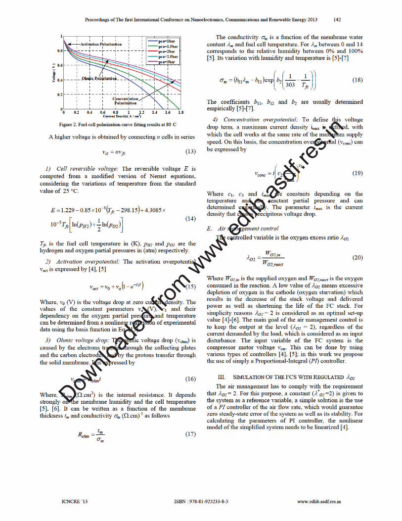
Proton exchange membrane fuel cells (PEMFC) combine hydrogen and oxygen over a platinum catalyst to produce electrochemical energy with water as the byproduct. Figure 2 shows the (vfc-i) characteristic of a typical single cell operating at Tfc=80 °C and different air pressure [5], [6]. The variation of individual cell voltage is found from the maximum cell voltage and the various voltage losses. Multiple factors contribute to the irreversible losses (voltage drop) in real fuel cell that cause the cell voltage to be less than its ideal potential [5]-[7]. The losses, which are also called polarization, irreversibility, or over voltage, over potential, originate primarily from three sources: a) activation polarization, b) ohmic polarization, and c) concentration (mass transport) polarization. Each of these is associated with a voltage drop and they are dominant in different regions of current density. Figure 2 shows the different regions and the corresponding polarization effects. The ideal voltage is the maximum voltage that each cell in the stack can produce at a given temperature with the partial pressure of the reactants and products known. The output voltage of a single cell vfc can be given by [5]-[8]
concohmactfc vvvEv −−−= (12)
Where E is the thermodynamic potential of the cell, it represents the no-load reversible voltage, vact is the activation overpotential, vohm is the ohmic overpotential and vconc is the concentration overpotential.
Proceedings of The first International Conference on Nanoelectronics, Communications and Renewable Energy 2013 141
ICNCRE ’13 ISBN : 978-81-925233-8-5 www.edlib.asdf.res.in
Downloaded fro
m w
ww.e
dlib
.asd
f.re
s.in
Downloaded fro
m w
ww.e
dlib
.asd
f.re
s.in

Downloaded fro
m w
ww.e
dlib
.asd
f.re
s.in

Downloaded fro
m w
ww.e
dlib
.asd
f.re
s.in