Novel Ni catalysts for methane decomposition to hydrogen and carbon nanofibers
13
Journal of Catalysis 238 (2006) 412–424 www.elsevier.com/locate/jcat Novel Ni catalysts for methane decomposition to hydrogen and carbon nanofibers Yong Li, Baocai Zhang, Xiaowei Xie, Junlong Liu, Yide Xu, Wenjie Shen ∗ State Key Laboratory of Catalysis, Dalian Institute of Chemical Physics, Chinese Academy of Sciences, Dalian 116023, China Received 11 November 2005; revised 20 December 2005; accepted 24 December 2005 Available online 27 January 2006 Abstract Novel nickel oxides with controlled crystalline size and fibrous shape were successfully prepared by precipitation of nickel acetate and sodium carbonate aqueous solution with the mediation of ethylene glycol. The precipitation media and temperature were found to play crucial roles in determining the crystalline size and shape of the nickel oxides. The NiO prepared in the aqueous solutions exhibited mainly spherical particles with few nanorods, whereas the NiO samples prepared in the solution of ethylene glycol could be of spherical, fibrous, or nanorod shape, depending on the precipitation temperature. In particular, the nickel hydroxide precipitate obtained in the solution of ethylene glycol at 393 K was α-Ni(OH) 2 with hydrotalcite-like structures; further calcination of this precipitate at 573–1073 K resulted in the formation of nickel oxides with similar fibrous shapes and crystalline size of 3.0–8.1 nm. Similar metallic Ni crystalline size of about 11 nm and fibrous structure were obtained by reduction of these NiO samples with hydrogen at 773 K. When further exposed to the reaction of methane decomposition, the metallic Ni crystallines still exhibited similar evolution behavior and rapidly stabilized at the critical size of 17–18 nm. Consequently, very close catalytic activities for methane decomposition over these novel Ni catalysts were observed with the carbon yields of 354–398 g C /g Ni . The Ni crystallines departed from the fibrous structures and gradually aggregated into particles by the dissociation of the deposited carbons. These nickel particles were then highly dispersed on the in situ produced carbon, which can inhibit the further growth of nickel particle. As a result, the initial fibrous structure morphology of the metallic nickel was gradually turned into pear-like shapes. © 2006 Elsevier Inc. All rights reserved. Keywords: Ni Catalyst; Ethylene glycol; Fibrous shape; Methane decomposition; Carbon nanofiber 1. Introduction Catalytic decomposition of methane has recently received much attention as a potentially economical route for produc- ing CO-free hydrogen that can be used directly as a fuel for H 2 –O 2 cells [1–3]. Ni-based catalysts were extensively studied for methane decomposition due to their relatively higher ac- tivities compared with other transition metals [3–6]. Because the catalytic activity of the Ni catalysts decreased with time on stream due to the continuous deposition of carbons, the effec- tive catalyst should exhibit sufficient carbon storage capacity on a per-gram basis of nickel, in addition to reasonable activity to- ward methane decomposition at relatively lower temperatures. * Corresponding author. Fax: +86 411 84694447. E-mail address: [email protected] (W. Shen). Because the most important factor influencing carbon yield during methane decomposition is the particle size of the metal- lic nickel, much attention has been given to disperse and stabi- lize nickel particles by selecting the appropriate support [7–12]. Metallic nickel supported on oxides has been the most com- monly used catalysts for methane decomposition. It was re- ported that a typical 40%Ni/SiO 2 catalyst could give a carbon yield as high as 491 g C /g Ni during methane decomposition at 773 K [11]. Using niobium oxide (Nb 2 O 5 ) to support 50.8%Ni and 21.2% of copper as a promoter, the yield of deposited carbon from methane reached 743 g C /g Ni at 873 K [12]. It was also found that 75%Ni–15%Cu–Al 2 O 3 catalysts prepared by coprecipitation provided a carbon yield of 700 g C /g Ni at 898 K [10]. When taking into account the application of carbon fibers, however, the catalyst components should be removed or separated from the deposited carbons [13,14]. Nickel can be practically and easily removed by leaching with acidic aque- 0021-9517/$ – see front matter © 2006 Elsevier Inc. All rights reserved. doi:10.1016/j.jcat.2005.12.027
-
Upload
independent -
Category
Documents
-
view
1 -
download
0
Transcript of Novel Ni catalysts for methane decomposition to hydrogen and carbon nanofibers
Journal of Catalysis 238 (2006) 412–424
www.elsevier.com/locate/jcat
Novel Ni catalysts for methane decomposition to hydrogenand carbon nanofibers
Yong Li, Baocai Zhang, Xiaowei Xie, Junlong Liu, Yide Xu, Wenjie Shen ∗
State Key Laboratory of Catalysis, Dalian Institute of Chemical Physics, Chinese Academy of Sciences, Dalian 116023, China
Received 11 November 2005; revised 20 December 2005; accepted 24 December 2005
Available online 27 January 2006
Abstract
Novel nickel oxides with controlled crystalline size and fibrous shape were successfully prepared by precipitation of nickel acetate and sodiumcarbonate aqueous solution with the mediation of ethylene glycol. The precipitation media and temperature were found to play crucial roles indetermining the crystalline size and shape of the nickel oxides. The NiO prepared in the aqueous solutions exhibited mainly spherical particles withfew nanorods, whereas the NiO samples prepared in the solution of ethylene glycol could be of spherical, fibrous, or nanorod shape, depending onthe precipitation temperature. In particular, the nickel hydroxide precipitate obtained in the solution of ethylene glycol at 393 K was α-Ni(OH)2with hydrotalcite-like structures; further calcination of this precipitate at 573–1073 K resulted in the formation of nickel oxides with similar fibrousshapes and crystalline size of 3.0–8.1 nm. Similar metallic Ni crystalline size of about 11 nm and fibrous structure were obtained by reductionof these NiO samples with hydrogen at 773 K. When further exposed to the reaction of methane decomposition, the metallic Ni crystallinesstill exhibited similar evolution behavior and rapidly stabilized at the critical size of 17–18 nm. Consequently, very close catalytic activities formethane decomposition over these novel Ni catalysts were observed with the carbon yields of 354–398 gC/gNi. The Ni crystallines departedfrom the fibrous structures and gradually aggregated into particles by the dissociation of the deposited carbons. These nickel particles were thenhighly dispersed on the in situ produced carbon, which can inhibit the further growth of nickel particle. As a result, the initial fibrous structuremorphology of the metallic nickel was gradually turned into pear-like shapes.© 2006 Elsevier Inc. All rights reserved.
Keywords: Ni Catalyst; Ethylene glycol; Fibrous shape; Methane decomposition; Carbon nanofiber
1. Introduction
Catalytic decomposition of methane has recently receivedmuch attention as a potentially economical route for produc-ing CO-free hydrogen that can be used directly as a fuel forH2–O2 cells [1–3]. Ni-based catalysts were extensively studiedfor methane decomposition due to their relatively higher ac-tivities compared with other transition metals [3–6]. Becausethe catalytic activity of the Ni catalysts decreased with time onstream due to the continuous deposition of carbons, the effec-tive catalyst should exhibit sufficient carbon storage capacity ona per-gram basis of nickel, in addition to reasonable activity to-ward methane decomposition at relatively lower temperatures.
* Corresponding author. Fax: +86 411 84694447.E-mail address: [email protected] (W. Shen).
0021-9517/$ – see front matter © 2006 Elsevier Inc. All rights reserved.doi:10.1016/j.jcat.2005.12.027
Because the most important factor influencing carbon yieldduring methane decomposition is the particle size of the metal-lic nickel, much attention has been given to disperse and stabi-lize nickel particles by selecting the appropriate support [7–12].Metallic nickel supported on oxides has been the most com-monly used catalysts for methane decomposition. It was re-ported that a typical 40%Ni/SiO2 catalyst could give a carbonyield as high as 491 gC/gNi during methane decomposition at773 K [11]. Using niobium oxide (Nb2O5) to support 50.8%Niand 21.2% of copper as a promoter, the yield of depositedcarbon from methane reached 743 gC/gNi at 873 K [12]. Itwas also found that 75%Ni–15%Cu–Al2O3 catalysts preparedby coprecipitation provided a carbon yield of 700 gC/gNi at898 K [10]. When taking into account the application of carbonfibers, however, the catalyst components should be removed orseparated from the deposited carbons [13,14]. Nickel can bepractically and easily removed by leaching with acidic aque-
Y. Li et al. / Journal of Catalysis 238 (2006) 412–424 413
ous, but the separation of the support materials, like Al2O3
and SiO2, may be quite burdensome [15]. Thus, various car-bons were used to support the nickel particles, and a secondarycarbon yield of 268.5 gC/gNi was obtained over a Ni/CFC (cat-alytic filamentous carbon) catalyst [16]. Obviously, the carbon-supported nickel catalyst usually gave a much lower carbonyield compared with that of the Ni particles supported by metaloxides [15,16].
To improve the overall efficiency of the process, attemptswere made to prepare pure nickel catalysts without a texturalpromoter. Unfortunately, the pure Ni catalyst showed rapid de-activation due to the severe aggregation of nickel particles un-der reaction conditions and gave a much lower carbon yield(∼10 gC/gNi). But the addition of 10% Al2O3 or SiO2 causeda nickel particle size decrease from 65 to 11 nm and carbonyields of 161–385 gC/gNi [7,9]. Clearly, the textural promoteris the crucial component in formulating the effective nickel cat-alysts, and their role is to stabilize the easily aggregated metallicnickel particles. Perhaps for this reason, there still has been nosuccessful report on using pure Ni catalyst for methane decom-position with reasonable activity and acceptable carbon storagecapacity.
Meanwhile, it is also interesting to note that the synthesisof nickel oxides with controlled particle sizes and morpholo-gies is becoming one of the hot topics in recent materialssciences. Thermal decomposition of solid nickel precursors,like nickel sol–gel complex and nickel hydroxides, were usedto produce nanocrystalline NiO materials [17,18]. These pre-pared NiO materials are nearly spherical nanoparticles and thustend to aggregate into rather larger particles when calcined athigher temperatures. The reported NiO materials gave smallparticle sizes (<10 nm) only after calcination at low temper-ature (�673 K), whereas the NiO particles rapidly aggregatedinto very large nanoparticles (>20 nm) after high-temperaturecalcination (�973 K). Meanwhile, there have been only fewreports on the morphology-controlled synthesis of NiO materi-als. Nanorings and nanosheets of nickel oxides have been pre-pared by thermal calcinations of the corresponding β-Ni(OH)2
[19,20]. But these studies were aimed at preparing nanosizedNiO materials with specific morphological shapes, and little at-tention was paid to their catalytic applications.
In the present study, pure nickel oxides with controlled crys-talline sizes and morphologies were successfully prepared byprecipitation of nickel acetate and sodium carbonate aqueoussolution with the mediation of ethylene glycol. The influenceof preparation parameters on the physical properties of thenickel oxides and the catalytic behaviors for methane decom-position of the obtained Ni catalysts was extensively inves-tigated by X-ray diffraction (XRD), temperature-programmedreduction (TPR), and transmission electron microscopy (TEM)techniques. The crystalline size and the morphological featuresof Ni were correlated with the catalytic activity of methanedecomposition by following the evolution of nickel oxides tometallic nickel particles during hydrogen reduction and subse-quent methane decomposition.
2. Experimental
2.1. Preparation of NiO catalysts
The nickel oxides were prepared by precipitation of nickelacetate dissolved in ethylene glycol with sodium carbonateaqueous solution at 353–433 K. A solution containing 0.05 molof nickel acetate (Ni(OAc)2 · 4H2O) and 150 mL of ethyleneglycol (EG) was gradually heated to the desired temperatures(353–433 K) under stirring and maintained at the same tem-perature for 30 min. Then 500 mL of 0.2 M Na2CO3 aqueoussolution was slowly added to the Ni-EG solution, with a finalpH value of about 10. The precipitate was aged in the motherliquid for another 1 h. After being filtered and washed thor-oughly with distilled water, the nickel hydroxide precipitate wasdried at 373 K overnight and finally calcined in air at 673 K for4 h. Depending on the precipitation temperature, the obtainedsolid was designed as NiO-EG-T , where T refers to the tem-perature of precipitation (in K).
For comparison, a NiO sample was also prepared by precip-itation of nickel acetate dissolved in water with sodium carbon-ate aqueous solution at 353 K in the same procedure describedabove. The sample thus obtained was designed as NiO-H2O-353.
To investigate the effect of calcination temperature on thephysiochemical properties and catalytic features of the NiO ma-terials, the nickel hydroxide precipitate prepared in the solutionof ethylene glycol at 393 K was further calcined in air at 773–1073 K for 4 h, resulting in NO samples of varying crystallinesizes and morphologies.
2.2. Catalyst characterization
The N2 adsorption–desorption isotherms were performedusing a Nova 4200e (Quantachrome) system operated at 77 K.Before these measurements, the sample was degassed by vac-uum at 573 K for 5 h. The BET surface area was calculated froma multipoint BET analysis of the nitrogen adsorption isotherms.
The X-ray powder diffraction (XRD) patterns were recordedon a D/MAX 2500 X-ray diffractometer (Rigaku), using Cu-Kα radiation operated at 40 kV and 100 mA. In situ XRDmeasurements for the reduction of the NiO samples were per-formed in a high-temperature chamber installed in the diffrac-tometer. The NiO was pressed into flakes and mounted in thechamber. After heating to 773 K in the flow of Ar, pure hy-drogen was introduced into the chamber and kept at 773 K for1 h, after which the XRD patterns were recorded. The meancrystallite sizes of nickel and NiO were calculated from theScherrer equation, where the particle shape factor was takenas 0.9 [21].
The TEM images were obtained with a JEOL JEM-2000EXoperated at 100 kV. The HRTEM images were obtained witha Philips Tecnai G220 operated at 200 kV. Specimens wereprepared by ultrasonically suspending the sample in ethanol.A drop of the suspension was then applied onto clean holycopper grids and dried in air. For TEM observation of the Nicatalyst, the NiO sample was first reduced with hydrogen in
414 Y. Li et al. / Journal of Catalysis 238 (2006) 412–424
a continuous-flow fixed-bed reactor at 773 K for 1 h. Afterbeing cooled to room temperature under Ar flow, anhydrousethanol was introduced through a syringe pump with Ar as acarrier gas until the reduced sample was completely immersed.Then it was quickly transferred and stored in the bottle ofethanol.
Temperature-programmed reduction (TPR) was performedin a conventional setup equipped with a thermal conductiv-ity detector. In typical runs, 50 mg NiO samples were usedand heated to 673 K (10 K/min) under N2 flow (40 mL/min)and kept at this temperature for 0.5 h to remove the adsorbedcarbonates and hydrates. After cooling down to room temper-ature and introducing the reduction agent of 20 vol% H2/N2(40 mL/min), the temperature was then programmed to risefrom 303 to 1073 K at a ramp rate of 10 K/min.
Raman spectroscopes of the deposited carbon nanofiberswere obtained over a homemade UV Raman spectrometer.A 325-nm laser line from Kimmon was chosen as the excita-tion source. The power of the UV laser line was 4.0 mW. Thewavenumber of Raman spectra was corrected, and the spec-tra error was ±2 cm−1. The value of ID/IG was estimated bycurve-fitting of the Raman spectrum using Gauss function.
2.3. Catalytic activity test
Methane decomposition reaction was carried out in a conti-nuous-flow fixed-bed quartz reactor at 773 K under atmosphericpressure. A 40-mg sample of NiO (40–60 mesh) was loaded andprereduced with pure hydrogen (20 mL/min) at 773 K for 1 hbefore the reaction. The Ni catalyst was then flushed with Arfor 0.5 h. CH4 (99.995% purity, 60 mL/min) was then intro-duced with a gas hourly space velocity of 90,000 mL/(gcat h)through a mass flow controller. To eliminate the space lim-itation for carbon growth, the reactor had an internal diam-eter of 28 mm and length of 250 mm. The effluents fromthe reactor were analyzed by on-line gas chromatography.Over all of the catalysts, hydrogen was detected as the onlygaseous product, indicating that methane decomposition oc-curs selectively as CH4 → 2H2 + C. Accordingly, methaneconversion was calculated from the amounts of hydrogen pro-duced.
3. Results and discussion
3.1. Effect of preparation parameters
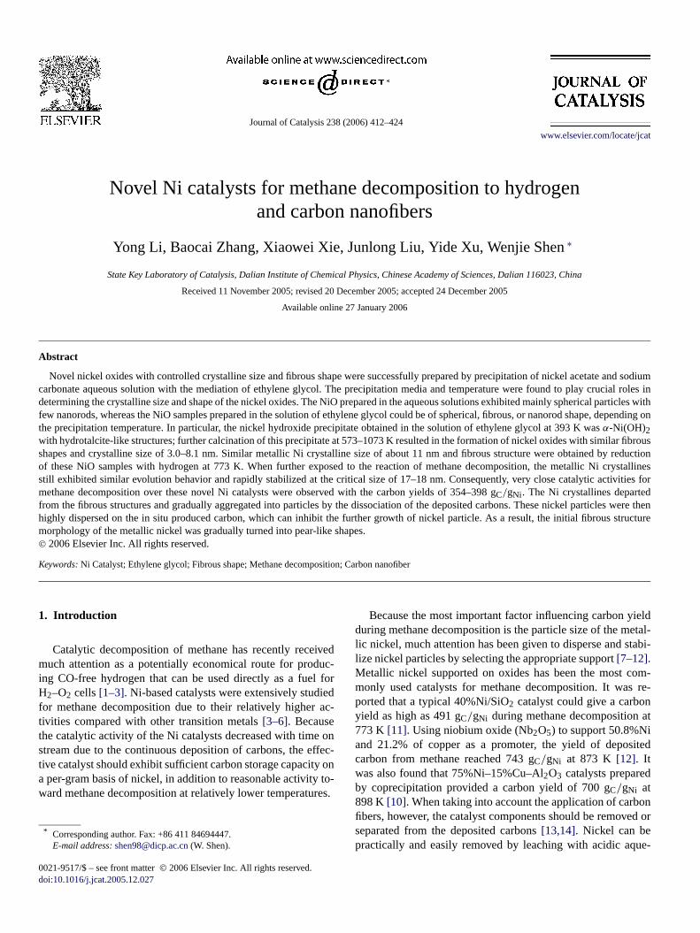
Fig. 1 shows the XRD patterns of the nickel oxides obtainedby calcination of the nickel hydroxide precipitates at 673 K,which were prepared in water and ethylene glycol. Clearly,all of the samples showed a typical face-center cubic struc-ture of NiO (JCPDS#4-835). The NiO-H2O-353 had the largestcrystalline size (8.4 nm) and a surface area of 78 m2/g. Thecrystalline sizes and the surface areas of the samples preparedin ethylene glycol were strongly dependent on the precipita-tion temperature. Precipitation at 353 and 433 K resulted insimilar NiO crystalline sizes of 6.8–7.1 nm and close surfaceareas of 78–93 m2/g, whereas the NiO-EG-393 sample gave
Fig. 1. XRD profiles of the nickel oxides.
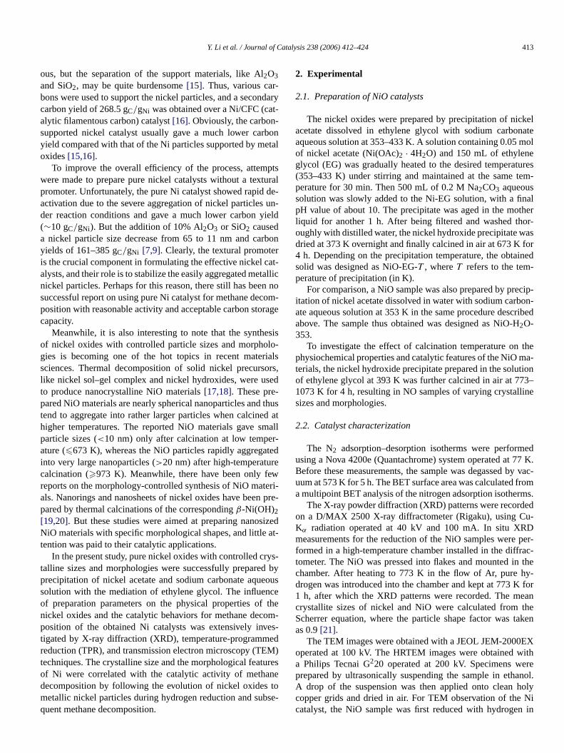
the smallest crystalline size (4.0 nm) and the largest surfacearea (123 m2/g). Fig. 2 gives the corresponding TEM imagesof the nickel oxides. Clearly, the morphology was determinedby the preparation conditions as well. Precipitation in waterled mainly to the formation of spherical particles (10–20 nm)and a few nanorods of NiO. The morphology of the nickel ox-ides prepared in ethylene glycol solutions was significantly re-lated to the precipitation temperature. The NiO-EG-353 sampleexhibited aggregated spherical particles, and the NiO-EG-393sample showed fibrous shapes and interlayered structures withno spherical particles. The NiO-EG-433 sample consisted ofnanorods (mainly NiO) and spherical particles.
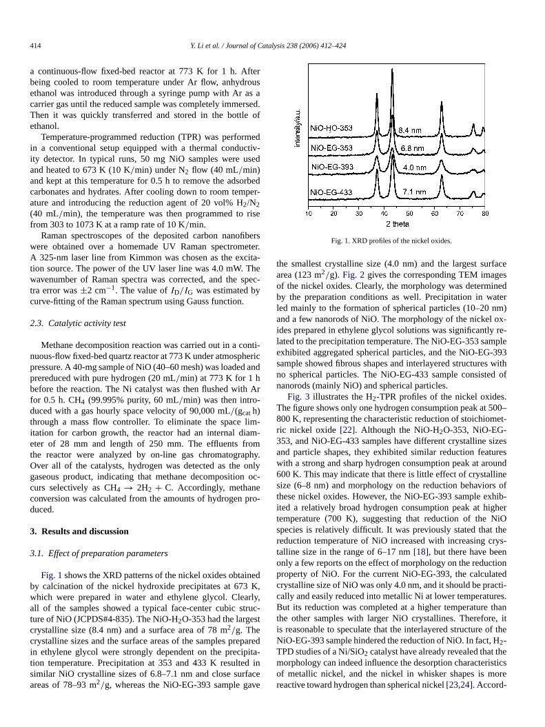
Fig. 3 illustrates the H2-TPR profiles of the nickel oxides.The figure shows only one hydrogen consumption peak at 500–800 K, representing the characteristic reduction of stoichiomet-ric nickel oxide [22]. Although the NiO-H2O-353, NiO-EG-353, and NiO-EG-433 samples have different crystalline sizesand particle shapes, they exhibited similar reduction featureswith a strong and sharp hydrogen consumption peak at around600 K. This may indicate that there is little effect of crystallinesize (6–8 nm) and morphology on the reduction behaviors ofthese nickel oxides. However, the NiO-EG-393 sample exhib-ited a relatively broad hydrogen consumption peak at highertemperature (700 K), suggesting that reduction of the NiOspecies is relatively difficult. It was previously stated that thereduction temperature of NiO increased with increasing crys-talline size in the range of 6–17 nm [18], but there have beenonly a few reports on the effect of morphology on the reductionproperty of NiO. For the current NiO-EG-393, the calculatedcrystalline size of NiO was only 4.0 nm, and it should be practi-cally and easily reduced into metallic Ni at lower temperatures.But its reduction was completed at a higher temperature thanthe other samples with larger NiO crystallines. Therefore, itis reasonable to speculate that the interlayered structure of theNiO-EG-393 sample hindered the reduction of NiO. In fact, H2-TPD studies of a Ni/SiO2 catalyst have already revealed that themorphology can indeed influence the desorption characteristicsof metallic nickel, and the nickel in whisker shapes is morereactive toward hydrogen than spherical nickel [23,24]. Accord-
Y. Li et al. / Journal of Catalysis 238 (2006) 412–424 415
Fig. 2. TEM images of the nickel oxides: (A) NiO-H O-353, (B) NiO-EG-353, (C) NiO-EG-393, (D) NiO-EG-433.
2Fig. 3. TPR profiles of the nickel oxides.
ingly, the interlayered structure of fibrous NiO may be ratherstable under hydrogen atmosphere compared with the spheri-cal particles and thus may lead to significant differences in thereduction features compared with other samples with sphericalNiO particles.
3.2. Methane decomposition
The NiO samples were first reduced into metallic nickelwith hydrogen at 773 K, and then tested for methane decom-
position. Fig. 4 depicts the methane conversions as a functionof time-on-stream, and the accumulated carbon decompositionand hydrogen yield were accordingly calculated. It is surpris-ing that the NiO-H2O-353 did not show any catalytic activ-ity toward methane decomposition, whereas the NiO samplesprepared in the solution of ethylene glycol showed differingcatalytic activities, depending on the precipitation temperature.The NiO-EG-353 sample exhibited pronounced catalytic activ-ity for methane decomposition with 60 h of time on stream, withaccumulated carbon and hydrogen yields of 271 gC/gNi and2651 molH2/molNi, respectively. The NiO-EG-393 sample gavethe highest methane conversion with rather prolonged catalyticactivity for 75 h, and the accumulated carbon and hydrogenyields approached 398 gC/gNi and 3894 molH2/molNi. How-ever, the NiO-EG-433 sample gave only marginal methane con-versions for about 5 h, and the accumulated carbon and hydro-gen yields were calculated as 3.4 gC/gNi and 33 molH2/molNi.Thus, it seems true that both the precipitation media and theprecipitation temperature play crucial roles in determining thecatalytic properties of the Ni catalysts, probably through ef-fective control of the crystalline and/or particle size as wellas the morphology of the nickel hydroxide precipitates andthe nickel oxides. In particular, precipitation in ethylene gly-col at 393 K led to the formation of stable α-Ni(OH)2 withhydrotalcite-like structure, and further calcination of this nickelhydroxide resulted in the formation of NiO-EG-393 with fi-

416 Y. Li et al. / Journal of Catalysis 238 (2006) 412–424
Fig. 4. Methane conversion as a function of time-on-stream over the Ni cata-lysts originated by hydrogen reduction of the nickel oxides at 773 K. (Reac-tion temperature, 773 K; catalyst, 0.040 g; methane, 101 kPa; and flow rate,60 mL/min.)
brous shapes. Unsupported Ni catalysts have been preparedby conventional precipitation method in aqueous solution andalso tested for methane decomposition in previous studies[7,9]. But these pure Ni catalysts only gave very low carbonyields of about 10 gC/gNi, similar to case of the NiO-EG-433.When small amounts of Al2O3 or SiO2 were used to sup-port the nickel oxides, considerable increases in carbon yields(161–384 gC/gNi) were observed. Notably, the carbon yieldof 398 gC/gNi achieved over the NiO-EG-393 was slightlyhigher than the most promising value of 384 gC/gNi over a90%Ni/SiO2 catalyst reported to date [9]. Thus, the Ni cata-lyst prepared by precipitation of nickel acetate at 393 K withthe mediation of ethylene glycol could be an excellent candi-date for methane decomposition.
3.3. Particle size and morphology of the reduced metallicnickel
From the reaction results of methane decomposition, itseems that the initial particle size and morphology of nickeloxide precursors had important effects on the catalytic per-formance of the reduced Ni catalysts. Because the metallicnickel generated from hydrogen reduction of NiO is the ac-tive component for methane decomposition, it is necessaryto establish the relationship between the particle or crys-talline size of the metallic nickel and the methane conver-sion. Fig. 5 shows the XRD patterns of the Ni catalysts ob-tained by reduction of NiO samples with hydrogen at 773 K.It can be seen that NiO was completely reduced to metallicnickel (JCPDS#4-850). Clearly, the crystalline sizes of metal-lic nickel were greatly increased (by about threefold) com-pared with their corresponding NiO precursors (Fig. 1). If thenickel crystalline size is correlated to the catalytic behaviorof methane decomposition, then it can be readily seen thatthe metallic Ni with crystalline size of about 10.8 nm hadthe highest carbon and hydrogen yields and that the metal-lic Ni with crystalline size of about 20 nm produced a rel-
Fig. 5. XRD patterns of the Ni catalysts obtained by hydrogen reduction of theNiO precursors at 773 K.
atively lower carbon yield. Increasing the Ni crystalline sizeto about 24 nm led to extremely low catalytic activity, andfurther increasing the size up to 26 nm resulted in total in-activity toward methane decomposition. Thus, it appears thatthe metallic nickel with crystalline size of 10–20 nm is suit-able for methane decomposition. The methane decompositionreaction depends critically on the crystalline size of metallicnickel, with dramatically decreased catalytic activity with in-creasing crystalline size. This observation is consistent withprevious reports concerning the effect of Ni crystalline sizeon methane decomposition over various supported nickel cat-alysts. Investigation of methane decomposition over a seriesof 90%Ni/SiO2 catalysts revealed that nickel crystalline sizesof 10–40 nm gave similar carbon yields of 300–384 gC/gNi,whereas further increasing the nickel crystalline size to 60 nmdrastically decreased the carbon yield to 2 gC/gNi [9]. Sim-ilarly, 96%Ni/SiO2 catalysts with nickel crystalline sizes of20 nm showed the highest carbon yield of 300 gC/gNi, andthe carbon yields greatly decreased (to 222 and 107 gC/gNi)when Ni crystalline sizes were slightly increased (to 25 and38 nm, respectively). For lower nickel loading systems, studiesover a 15%Ni/CFC catalyst also concluded that Ni crystallinesizes of 30–70 nm were suitable for the growth of carbonfilaments during methane decomposition [8,25]. The most ef-fective crystalline size of Ni for the growth of filamentouscarbon was found to be 10–60 nm over a 23.3%Ni/SiO2 cat-alyst [26]. It was further observed that the optimal growthrate of carbon nanofibers could be achieved over Ni crystalsaround 34 nm in size if supported by hydrotalcite materi-als [27].
Although it is obvious that smaller Ni crystalline sizes showhigher catalytic activity for methane decomposition, there isa significant discrepancy among the reported optimal metal-lic nickel crystalline sizes for methane decomposition, whichstrongly depends on the support and the Ni loading. For the cur-rent unsupported Ni catalysts, metallic nickel with crystallinesize of 10–20 nm was found to be suitable for methane decom-position, but increasing the crystalline size to 26 nm resultedin total inactivity. This extreme sensitivity of metallic nickel
Y. Li et al. / Journal of Catalysis 238 (2006) 412–424 417
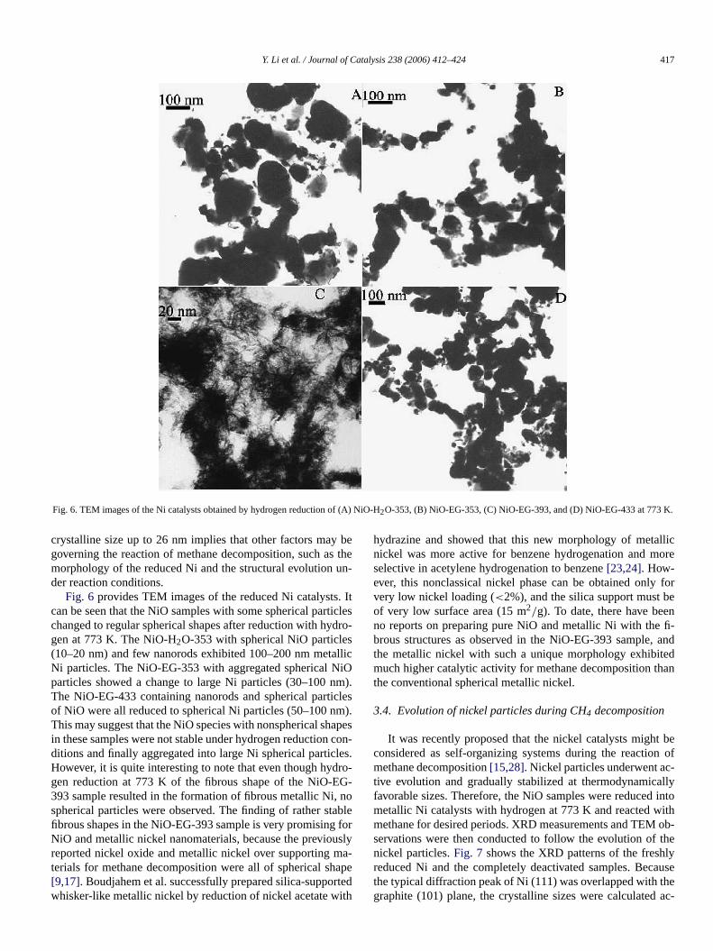
Fig. 6. TEM images of the Ni catalysts obtained by hydrogen reduction of (A) NiO-H2O-353, (B) NiO-EG-353, (C) NiO-EG-393, and (D) NiO-EG-433 at 773 K.
crystalline size up to 26 nm implies that other factors may begoverning the reaction of methane decomposition, such as themorphology of the reduced Ni and the structural evolution un-der reaction conditions.
Fig. 6 provides TEM images of the reduced Ni catalysts. Itcan be seen that the NiO samples with some spherical particleschanged to regular spherical shapes after reduction with hydro-gen at 773 K. The NiO-H2O-353 with spherical NiO particles(10–20 nm) and few nanorods exhibited 100–200 nm metallicNi particles. The NiO-EG-353 with aggregated spherical NiOparticles showed a change to large Ni particles (30–100 nm).The NiO-EG-433 containing nanorods and spherical particlesof NiO were all reduced to spherical Ni particles (50–100 nm).This may suggest that the NiO species with nonspherical shapesin these samples were not stable under hydrogen reduction con-ditions and finally aggregated into large Ni spherical particles.However, it is quite interesting to note that even though hydro-gen reduction at 773 K of the fibrous shape of the NiO-EG-393 sample resulted in the formation of fibrous metallic Ni, nospherical particles were observed. The finding of rather stablefibrous shapes in the NiO-EG-393 sample is very promising forNiO and metallic nickel nanomaterials, because the previouslyreported nickel oxide and metallic nickel over supporting ma-terials for methane decomposition were all of spherical shape[9,17]. Boudjahem et al. successfully prepared silica-supportedwhisker-like metallic nickel by reduction of nickel acetate with
hydrazine and showed that this new morphology of metallicnickel was more active for benzene hydrogenation and moreselective in acetylene hydrogenation to benzene [23,24]. How-ever, this nonclassical nickel phase can be obtained only forvery low nickel loading (<2%), and the silica support must beof very low surface area (15 m2/g). To date, there have beenno reports on preparing pure NiO and metallic Ni with the fi-brous structures as observed in the NiO-EG-393 sample, andthe metallic nickel with such a unique morphology exhibitedmuch higher catalytic activity for methane decomposition thanthe conventional spherical metallic nickel.
3.4. Evolution of nickel particles during CH4 decomposition
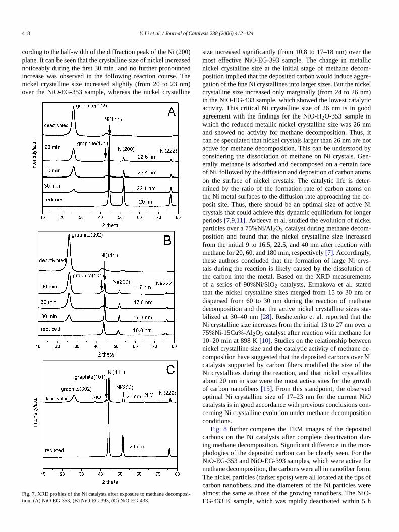
It was recently proposed that the nickel catalysts might beconsidered as self-organizing systems during the reaction ofmethane decomposition [15,28]. Nickel particles underwent ac-tive evolution and gradually stabilized at thermodynamicallyfavorable sizes. Therefore, the NiO samples were reduced intometallic Ni catalysts with hydrogen at 773 K and reacted withmethane for desired periods. XRD measurements and TEM ob-servations were then conducted to follow the evolution of thenickel particles. Fig. 7 shows the XRD patterns of the freshlyreduced Ni and the completely deactivated samples. Becausethe typical diffraction peak of Ni (111) was overlapped with thegraphite (101) plane, the crystalline sizes were calculated ac-
418 Y. Li et al. / Journal of Catalysis 238 (2006) 412–424
cording to the half-width of the diffraction peak of the Ni (200)plane. It can be seen that the crystalline size of nickel increasednoticeably during the first 30 min, and no further pronouncedincrease was observed in the following reaction course. Thenickel crystalline size increased slightly (from 20 to 23 nm)over the NiO-EG-353 sample, whereas the nickel crystalline
Fig. 7. XRD profiles of the Ni catalysts after exposure to methane decomposi-tion: (A) NiO-EG-353, (B) NiO-EG-393, (C) NiO-EG-433.
size increased significantly (from 10.8 to 17–18 nm) over themost effective NiO-EG-393 sample. The change in metallicnickel crystalline size at the initial stage of methane decom-position implied that the deposited carbon would induce aggre-gation of the fine Ni crystallines into larger sizes. But the nickelcrystalline size increased only marginally (from 24 to 26 nm)in the NiO-EG-433 sample, which showed the lowest catalyticactivity. This critical Ni crystalline size of 26 nm is in goodagreement with the findings for the NiO-H2O-353 sample inwhich the reduced metallic nickel crystalline size was 26 nmand showed no activity for methane decomposition. Thus, itcan be speculated that nickel crystals larger than 26 nm are notactive for methane decomposition. This can be understood byconsidering the dissociation of methane on Ni crystals. Gen-erally, methane is adsorbed and decomposed on a certain faceof Ni, followed by the diffusion and deposition of carbon atomson the surface of nickel crystals. The catalytic life is deter-mined by the ratio of the formation rate of carbon atoms onthe Ni metal surfaces to the diffusion rate approaching the de-posit site. Thus, there should be an optimal size of active Nicrystals that could achieve this dynamic equilibrium for longerperiods [7,9,11]. Avdeeva et al. studied the evolution of nickelparticles over a 75%Ni/Al2O3 catalyst during methane decom-position and found that the nickel crystalline size increasedfrom the initial 9 to 16.5, 22.5, and 40 nm after reaction withmethane for 20, 60, and 180 min, respectively [7]. Accordingly,these authors concluded that the formation of large Ni crys-tals during the reaction is likely caused by the dissolution ofthe carbon into the metal. Based on the XRD measurementsof a series of 90%Ni/SiO2 catalysts, Ermakova et al. statedthat the nickel crystalline sizes merged from 15 to 30 nm ordispersed from 60 to 30 nm during the reaction of methanedecomposition and that the active nickel crystalline sizes sta-bilized at 30–40 nm [28]. Reshetenko et al. reported that theNi crystalline size increases from the initial 13 to 27 nm over a75%Ni-15Cu%-Al2O3 catalyst after reaction with methane for10–20 min at 898 K [10]. Studies on the relationship betweennickel crystalline size and the catalytic activity of methane de-composition have suggested that the deposited carbons over Nicatalysts supported by carbon fibers modified the size of theNi crystallites during the reaction, and that nickel crystallitesabout 20 nm in size were the most active sites for the growthof carbon nanofibers [15]. From this standpoint, the observedoptimal Ni crystalline size of 17–23 nm for the current NiOcatalysts is in good accordance with previous conclusions con-cerning Ni crystalline evolution under methane decompositionconditions.
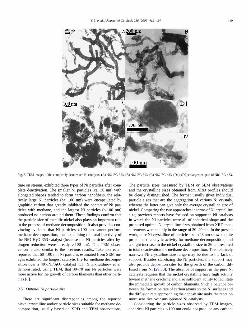
Fig. 8 further compares the TEM images of the depositedcarbons on the Ni catalysts after complete deactivation dur-ing methane decomposition. Significant difference in the mor-phologies of the deposited carbon can be clearly seen. For theNiO-EG-353 and NiO-EG-393 samples, which were active formethane decomposition, the carbons were all in nanofiber form.The nickel particles (darker spots) were all located at the tips ofcarbon nanofibers, and the diameters of the Ni particles werealmost the same as those of the growing nanofibers. The NiO-EG-433 K sample, which was rapidly deactivated within 5 h
Y. Li et al. / Journal of Catalysis 238 (2006) 412–424 419
Fig. 8. TEM images of the completely deactivated Ni catalysts: (A) NiO-EG-353, (B) NiO-EG-393, (C) NiO-EG-433, (D1)–(D2) enlargement part of NiO-EG-433.
time on stream, exhibited three types of Ni particles after com-plete deactivation. The smaller Ni particles (ca. 30 nm) withelongated shapes tended to form carbon nanofibers, the rela-tively large Ni particles (ca. 100 nm) were encapsulated bygraphitic carbon that greatly inhibited the contact of Ni par-ticles with methane, and the largest Ni particles (>100 nm)produced no carbon around them. These findings confirm thatthe particle size of metallic nickel also plays an important rolein the process of methane decomposition. It also provides con-vincing evidence that Ni particles >100 nm cannot performmethane decomposition, thus explaining the total inactivity ofthe NiO-H2O-353 catalyst (because the Ni particles after hy-drogen reduction were already >100 nm). This TEM obser-vation is also similar to the previous results. Takenaka et al.reported that 60–100 nm Ni particles estimated from SEM im-ages exhibited the longest catalytic life for methane decompo-sition over a 40%Ni/SiO2 catalyst [11]. Shaikhutdinov et al.demonstrated, using TEM, that 30–70 nm Ni particles weremore active for the growth of carbon filaments than other parti-cles [8].
3.5. Optimal Ni particle size
There are significant discrepancies among the reportednickel crystalline and/or particle sizes suitable for methane de-composition, usually based on XRD and TEM observations.
The particle sizes measured by TEM or SEM observationsand the crystalline sizes obtained from XRD profiles shouldbe clearly distinguished. The former usually gives individualparticle sizes that are the aggregation of various Ni crystals,whereas the latter can give only the average crystalline size ofnickel. Comparing the two approaches in terms of Ni crystallinesize, previous reports have focused on supported Ni catalystsin which the Ni particles were all of spherical shape and theproposed optimal Ni crystalline sizes obtained from XRD mea-surements were mainly in the range of 20–40 nm. In the presentwork, pure Ni crystalline of particle size <23 nm showed quitepronounced catalytic activity for methane decomposition, anda slight increase in the nickel crystalline size to 26 nm resultedin total deactivation for methane decomposition. This relativelynarrower Ni crystalline size range may be due to the lack ofsupport. Besides stabilizing the Ni particles, the support mayalso provide deposition sites for the growth of the carbon dif-fused from Ni [29,30]. The absence of support in the pure Nicatalysts requires that the nickel crystalline have high activitytoward methane cracking and also sufficient ability to facilitatethe immediate growth of carbon filaments. Such a balance be-tween the formation rate of carbon atoms on the Ni surfaces andthe diffusion rate approaching the deposit site make the reactionmore sensitive over unsupported Ni catalysts.
Considering the particle sizes observed by TEM images,spherical Ni particles >100 nm could not produce any carbon;
420 Y. Li et al. / Journal of Catalysis 238 (2006) 412–424
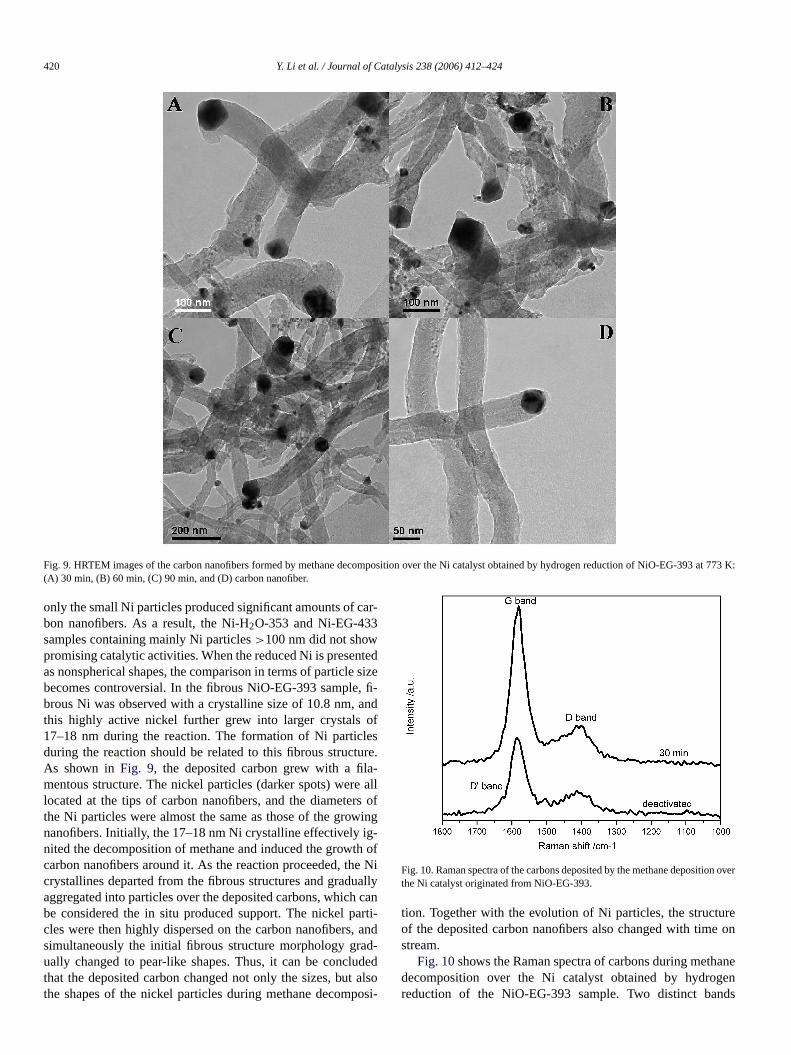
Fig. 9. HRTEM images of the carbon nanofibers formed by methane decomposition over the Ni catalyst obtained by hydrogen reduction of NiO-EG-393 at 773 K:(A) 30 min, (B) 60 min, (C) 90 min, and (D) carbon nanofiber.
only the small Ni particles produced significant amounts of car-bon nanofibers. As a result, the Ni-H2O-353 and Ni-EG-433samples containing mainly Ni particles >100 nm did not showpromising catalytic activities. When the reduced Ni is presentedas nonspherical shapes, the comparison in terms of particle sizebecomes controversial. In the fibrous NiO-EG-393 sample, fi-brous Ni was observed with a crystalline size of 10.8 nm, andthis highly active nickel further grew into larger crystals of17–18 nm during the reaction. The formation of Ni particlesduring the reaction should be related to this fibrous structure.As shown in Fig. 9, the deposited carbon grew with a fila-mentous structure. The nickel particles (darker spots) were alllocated at the tips of carbon nanofibers, and the diameters ofthe Ni particles were almost the same as those of the growingnanofibers. Initially, the 17–18 nm Ni crystalline effectively ig-nited the decomposition of methane and induced the growth ofcarbon nanofibers around it. As the reaction proceeded, the Nicrystallines departed from the fibrous structures and graduallyaggregated into particles over the deposited carbons, which canbe considered the in situ produced support. The nickel parti-cles were then highly dispersed on the carbon nanofibers, andsimultaneously the initial fibrous structure morphology grad-ually changed to pear-like shapes. Thus, it can be concludedthat the deposited carbon changed not only the sizes, but alsothe shapes of the nickel particles during methane decomposi-
Fig. 10. Raman spectra of the carbons deposited by the methane deposition overthe Ni catalyst originated from NiO-EG-393.
tion. Together with the evolution of Ni particles, the structureof the deposited carbon nanofibers also changed with time onstream.
Fig. 10 shows the Raman spectra of carbons during methanedecomposition over the Ni catalyst obtained by hydrogenreduction of the NiO-EG-393 sample. Two distinct bands
Y. Li et al. / Journal of Catalysis 238 (2006) 412–424 421
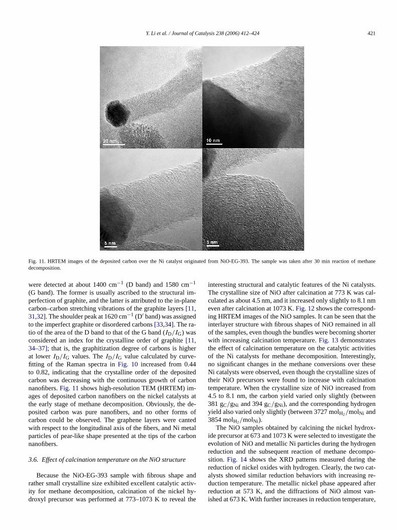
Fig. 11. HRTEM images of the deposited carbon over the Ni catalyst originated from NiO-EG-393. The sample was taken after 30 min reaction of methanedecomposition.
were detected at about 1400 cm−1 (D band) and 1580 cm−1
(G band). The former is usually ascribed to the structural im-perfection of graphite, and the latter is attributed to the in-planecarbon–carbon stretching vibrations of the graphite layers [11,31,32]. The shoulder peak at 1620 cm−1 (D′ band) was assignedto the imperfect graphite or disordered carbons [33,34]. The ra-tio of the area of the D band to that of the G band (ID/IG) wasconsidered an index for the crystalline order of graphite [11,34–37]; that is, the graphitization degree of carbons is higherat lower ID/IG values. The ID/IG value calculated by curve-fitting of the Raman spectra in Fig. 10 increased from 0.44to 0.82, indicating that the crystalline order of the depositedcarbon was decreasing with the continuous growth of carbonnanofibers. Fig. 11 shows high-resolution TEM (HRTEM) im-ages of deposited carbon nanofibers on the nickel catalysts atthe early stage of methane decomposition. Obviously, the de-posited carbon was pure nanofibers, and no other forms ofcarbon could be observed. The graphene layers were cantedwith respect to the longitudinal axis of the fibers, and Ni metalparticles of pear-like shape presented at the tips of the carbonnanofibers.
3.6. Effect of calcination temperature on the NiO structure
Because the NiO-EG-393 sample with fibrous shape andrather small crystalline size exhibited excellent catalytic activ-ity for methane decomposition, calcination of the nickel hy-droxyl precursor was performed at 773–1073 K to reveal the
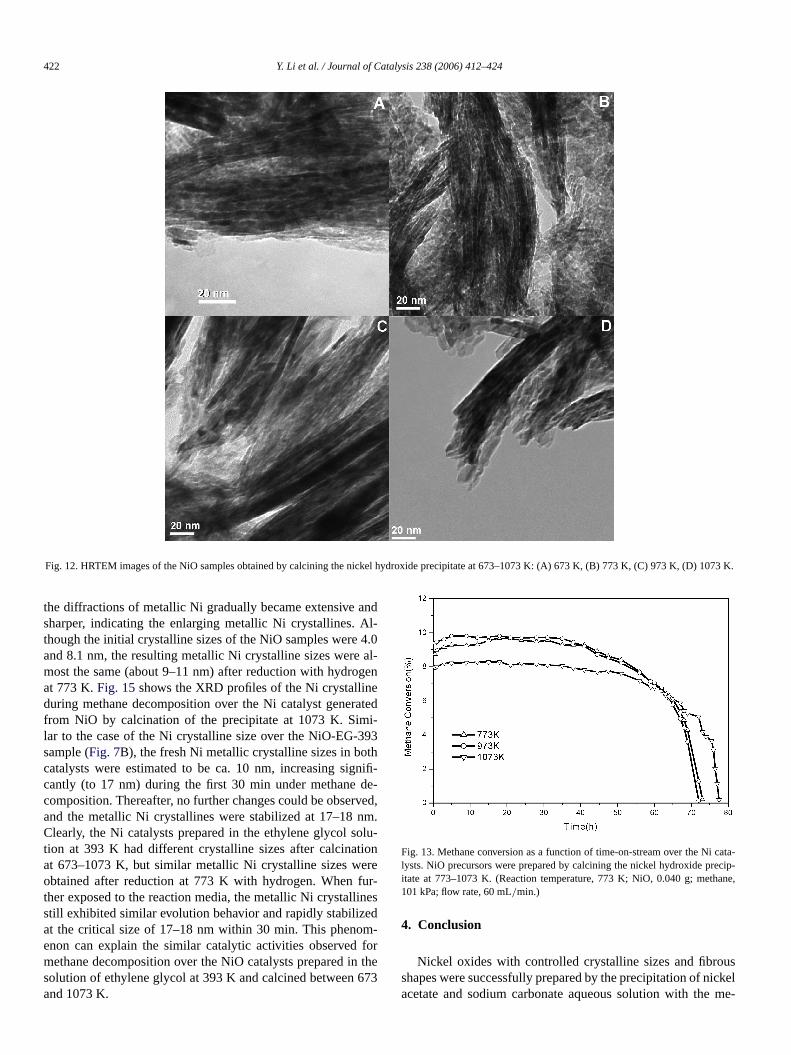
interesting structural and catalytic features of the Ni catalysts.The crystalline size of NiO after calcination at 773 K was cal-culated as about 4.5 nm, and it increased only slightly to 8.1 nmeven after calcination at 1073 K. Fig. 12 shows the correspond-ing HRTEM images of the NiO samples. It can be seen that theinterlayer structure with fibrous shapes of NiO remained in allof the samples, even though the bundles were becoming shorterwith increasing calcination temperature. Fig. 13 demonstratesthe effect of calcination temperature on the catalytic activitiesof the Ni catalysts for methane decomposition. Interestingly,no significant changes in the methane conversions over theseNi catalysts were observed, even though the crystalline sizes oftheir NiO precursors were found to increase with calcinationtemperature. When the crystalline size of NiO increased from4.5 to 8.1 nm, the carbon yield varied only slightly (between381 gC/gNi and 394 gC/gNi), and the corresponding hydrogenyield also varied only slightly (between 3727 molH2/molNi and3854 molH2/molNi).
The NiO samples obtained by calcining the nickel hydrox-ide precursor at 673 and 1073 K were selected to investigate theevolution of NiO and metallic Ni particles during the hydrogenreduction and the subsequent reaction of methane decompo-sition. Fig. 14 shows the XRD patterns measured during thereduction of nickel oxides with hydrogen. Clearly, the two cat-alysts showed similar reduction behaviors with increasing re-duction temperature. The metallic nickel phase appeared afterreduction at 573 K, and the diffractions of NiO almost van-ished at 673 K. With further increases in reduction temperature,
422 Y. Li et al. / Journal of Catalysis 238 (2006) 412–424
Fig. 12. HRTEM images of the NiO samples obtained by calcining the nickel hydroxide precipitate at 673–1073 K: (A) 673 K, (B) 773 K, (C) 973 K, (D) 1073 K.
the diffractions of metallic Ni gradually became extensive andsharper, indicating the enlarging metallic Ni crystallines. Al-though the initial crystalline sizes of the NiO samples were 4.0and 8.1 nm, the resulting metallic Ni crystalline sizes were al-most the same (about 9–11 nm) after reduction with hydrogenat 773 K. Fig. 15 shows the XRD profiles of the Ni crystallineduring methane decomposition over the Ni catalyst generatedfrom NiO by calcination of the precipitate at 1073 K. Simi-lar to the case of the Ni crystalline size over the NiO-EG-393sample (Fig. 7B), the fresh Ni metallic crystalline sizes in bothcatalysts were estimated to be ca. 10 nm, increasing signifi-cantly (to 17 nm) during the first 30 min under methane de-composition. Thereafter, no further changes could be observed,and the metallic Ni crystallines were stabilized at 17–18 nm.Clearly, the Ni catalysts prepared in the ethylene glycol solu-tion at 393 K had different crystalline sizes after calcinationat 673–1073 K, but similar metallic Ni crystalline sizes wereobtained after reduction at 773 K with hydrogen. When fur-ther exposed to the reaction media, the metallic Ni crystallinesstill exhibited similar evolution behavior and rapidly stabilizedat the critical size of 17–18 nm within 30 min. This phenom-enon can explain the similar catalytic activities observed formethane decomposition over the NiO catalysts prepared in thesolution of ethylene glycol at 393 K and calcined between 673and 1073 K.
Fig. 13. Methane conversion as a function of time-on-stream over the Ni cata-lysts. NiO precursors were prepared by calcining the nickel hydroxide precip-itate at 773–1073 K. (Reaction temperature, 773 K; NiO, 0.040 g; methane,101 kPa; flow rate, 60 mL/min.)
4. Conclusion
Nickel oxides with controlled crystalline sizes and fibrousshapes were successfully prepared by the precipitation of nickelacetate and sodium carbonate aqueous solution with the me-

Y. Li et al. / Journal of Catalysis 238 (2006) 412–424 423
Fig. 14. XRD patterns of the nickel oxides during hydrogen reduction process.NiO was obtained by calcination of the nickel hydroxide at: (A) 673 K and(B) 1073 K.
diation of ethylene glycol. The precipitation temperature wasfound to play crucial role in determining the crystalline size andshape of the NiO samples. Precipitation at 393 K resulted in theformation of α-Ni(OH)2 with a hydrotalcite-like structure, andfurther calcination of this precipitate precursor at 673–1073 Kled to the formation of nickel oxides with layered structures.The crystalline size of the NiO after calcination at 673 K was4.0 nm and increased only slightly to 8.1 nm even after cal-cination at 1073 K. On reduction with hydrogen at 773 K,the crystalline sizes of the obtained Ni catalysts were almostthe same (9.0–11.0 nm). More importantly, the reduced nickelmaintained the fibrous shapes of the initial NiO precursors.
The catalytic activity of the pure Ni catalysts for methanedecomposition was strongly related to the crystalline size ofthe reduced Ni. The Ni catalyst with crystalline size of about10.8 nm had the highest carbon and hydrogen yields, and thenickel crystalline of about 20 nm gave relatively lower carbonyields. Further increasing the nickel crystalline size to about24 nm led to extremely low catalytic activity, and an increase upto 26 nm resulted in total deactivation toward methane decom-position. Further evolution of the Ni particles during methane
Fig. 15. XRD patterns of the NiO catalysts obtained by calcining the nickelhydroxide precipitate at 1073 K after exposure to methane decomposition.
decomposition reaction suggested that the deposited carbonchanged not only the crystalline size, but also the morphologyof the metallic nickel. The Ni crystallines departed from the fi-brous structures and gradually changed to particles through thedissociation of the deposited carbons. The nickel particles werethen highly dispersed on the in situ produced carbon, inhibit-ing the further growth of nickel particle. As a result, the initialfibrous structure morphology of the metallic nickel graduallychanged to a pear-like shape.
References
[1] T. Zhang, M.D. Amiridis, Appl. Catal. A 167 (1998) 161.[2] T.V. Choudhary, C. Sivadinarayana, C.C. Chusuei, A. Klinghoffer, D.W.
Goodman, J. Catal. 199 (2001) 9.[3] R.A. Couttenye, M.H. De Vila, S.L. Suib, J. Catal. 233 (2005) 317.[4] M.A. Ermakova, D.Yu. Ermakov, G.G. Kuvshinov, Appl. Catal. A 201
(2000) 61.[5] S. Takenaka, H. Ogihara, I. Yamanaka, K. Otsuka, Appl. Catal. A 217
(2001) 101.[6] M.A. Ermakova, D.Yu. Ermakov, Catal. Today 77 (2002) 225.[7] L.B. Avdeeva, O.V. Goncharova, D.I. Kochubey, V.I. Zaikovskii, L.M.
Plyasova, B.N. Novgorodov, Sh.K. Shaikhutdinov, Appl. Catal. A 141(1996) 117.
[8] Sh.K. Shaikhutdinov, L.B. Avdeeva, B.N. Novgorodov, V.I. Zaikovskii,D.I. Kochubey, Catal. Lett. 47 (1997) 35.
[9] M.A. Ermakova, D.Yu. Ermakov, G.C. Kuvshinov, L.M. Plyasova, J. Ca-tal. 187 (1999) 77.
[10] T.V. Reshetenko, L.B. Avdeeva, Z.R. Ismagilov, A.L. Chuvilin, V.A.Ushakov, Appl. Catal. A 247 (2003) 51.
[11] S. Takenaka, S. Kobayashi, H. Ogihara, K. Otsuka, J. Catal. 217 (2003)79.
[12] J. Li, G. Lu, K. Li, W. Wang, J. Mol. Catal. A 221 (2004) 105.[13] A. Chambers, T. Nemes, N.M. Rodriguez, R.T.K. Baker, J. Phys. Chem.
B 102 (1998) 2251.[14] K.P. de Jong, J.W. Geus, Catal. Rev.-Sci. Eng. 42 (2000) 481.[15] K. Otsuka , H. Ogihara, S. Takenaka, Carbon 41 (2003) 223.[16] T.V. Reshetenko, L.B. Avdeeva, Z.R. Ismagilov, A.L. Chuvilin, V.B. Fene-
lonov, Catal. Today 102–103 (2005) 115.[17] L.C. Corrie, S. Jennifer, J.K. Kenneth, Langmuir 18 (2002) 1352.[18] C. Wang, G. Gau, S. Gau, C. Tang, J. Bi, Catal. Lett. 101 (2005).[19] J. Liang, Y. Li, Chem. Lett. 32 (2003) 1126.[20] Z. Liang, Y. Zhu, X. Hu, J. Phys. Chem. B 108 (2004) 3488.

424 Y. Li et al. / Journal of Catalysis 238 (2006) 412–424
[21] B.D. Cullity, Elements of X-Ray Diffraction, second ed., Addison–Wesley, Menlo Park, CA, 1978.
[22] S.D. Robertson, B.D. Mcnicol, J.H. de Bass, S.C. Kloet, J.W. Jenkins,J. Catal. 37 (1975) 424.
[23] A.G. Boudjahem, S. Monteverdi, M. Mercy, M.M. Bettahar, J. Catal. 221(2004) 325.
[24] A.G. Boudjahem, S. Monteverdi, M. Mercy, M.M. Bettahar, Catal.Lett. 97 (2004) 177.
[25] T.V. Reshetenko, L.B. Avdeeva, Z.R. Ismagilov, A.L. Chuvilin, Carbon 42(2004) 143.
[26] P. Wang, E. Tanabe, K. Ito, J. Jia, H. Morioka, T. Shishido, K. Takehira,Appl. Catal. A 231 (2002) 35.
[27] D. Chen, K.O. Christensen, E. Ochoa-Fernández, Z. Yu, B. Tøtdal, N. La-torre, A. Monzón, A. Holmen, J. Catal. 229 (2005) 82.
[28] M.A. Ermakova, D.Yu. Ermakov, L.M. Plyasova, G.C. Kuvshinov, Catal.Lett. 62 (1999) 3.
[29] R.T.K. Baker, Carbon 27 (1989) 315.[30] J.W. Snoeck, G.F. Froment, M. Fowles, J. Catal. 169 (1997) 240.[31] K. Sinha, J. Menendez, Phys. Rev. B 41 (1990) 10845.[32] R.J. Nemanich, S.A. Solin, Phys. Rev. B 20 (1979) 392.[33] H. Darmstadt, L. Sümmchen, J.M. Ting, U. Roland, S. Kaliaguine, C. Roy,
Carbon 35 (1997) 1581.[34] T. Jawhari, A. Roid, J. Casado, Carbon 33 (1995) 1561.[35] A. Cuesta, P. Dhamelincourt, J. Laureyns, A. Martinez-Alonso, J.M.D.
Tascon, Carbon 32 (1994) 1523.[36] J.O. Herrera, D.E. Resasco, Chem. Phys. Lett. 376 (2003) 302.[37] W.E. Alvarez, F. Pompeo, J.E. Herrera, L. Balzano, D.E. Resasco, Chem.
Mater. 14 (2002) 1853.