Differences between carbon nanofibers produced using Fe and Ni catalysts in a floating catalyst...
9
Differences between carbon nanofibers produced using Fe and Ni catalysts in a floating catalyst reactor Ignacio Martin-Gullon a, * , Jose ´ Vera a , Juan A. Conesa a , Jose ´ L. Gonza ´lez b , Ce ´sar Merino b a Chemical Engineering Department, University of Alicante, P.O. Box 99, 03080 Alicante, Spain b Grupo Antolı ´n Ingenierı ´a, Nanofiber Division, Ctra. Iru ´ n 244, 09007 Burgos, Spain Received 10 October 2005; accepted 17 December 2005 Available online 20 February 2006 Abstract Carbon nanofibers were produced by the catalytic CVD process by the floating catalyst method, in semi-industrial systems at tem- peratures above 1350 K. Iron-derived carbon nanofibers were produced from natural gas and xylene, using ferrocene as catalyst source, yielding a thickened submicron vapor grown carbon fibers with a core of multi-wall nanotubes. For the production of Ni derived nano- fibers, natural gas was used as the carbon feedstock, and the Ni was added in a nickel compound solution. When no sulfur is used, only soot was obtained, but when sulfur is added to the reactive feedstock, a highly graphitic and very nice stacked-cup-type nanofibers with no free-CVD thickened layer were produced. TEM-EDS analysis confirms that this type of stacked-cup carbon nanofiber is produced only with a partially molten catalyst and methane as hydrocarbon source. In fact, very few fibers have either a particle tip at the end or trapped metal particle inside the wide hollow core of this type of produced carbon material. Ó 2006 Elsevier Ltd. All rights reserved. Keywords: Carbon nanofibers; Chemical vapor deposition; Transmission electron microscopy; Microstructure 1. Introduction A method for growing catalytically carbon filaments with iron and a hydrocarbon feedstock was first patented in the 19th century [1], but the interest in the structure of these filaments and their properties emerged in the 1970s with the development of the transmission electron micros- copy, when the mechanistic proposals of Oberlin et al. [2] and Baker et al. [3] were reported. Basically, these fibrils are produced by the catalytic chemical vapor deposition (CVD) of carbon from a carbon source, and this type of fibers were named vapor grown carbon fibers (VGCF) to differentiate them from other types of carbon fibers (CF). In the 1980s, a great effort was made to develop a contin- uous method to produce VGCF [4], also named carbon nanofibers (CNF) if the diameter was lower than 500 nm. The discovery of carbon nanotubes (CNT) by Ijima in the early 1990s [5], which are mainly produced by catalytic CVD, increased the interest in the production of different types of carbon nanofilaments (CNT, CNF or VGCF) and their applications, such as in hydrogen storage [6], cat- alyst supports [7], field emission [8], memory devices [9] and fillers for polymer composites [10,11]. Therefore, there is a very extensive amount of papers in the literature reporting the production of CNT and CNF by different methods, conditions, catalysts (Fe, Ni, Co and Cu) and carbon sources, and often there is some confusion about which material produced is adequate for each application. As mentioned above, all carbon nanofilaments are pro- duced by catalytic CVD from a carbon feedstock (light or aromatic hydrocarbons, CO) using an elemental transition metal (Fe, Ni, Co and Cu) as catalyst. This process usually 0008-6223/$ - see front matter Ó 2006 Elsevier Ltd. All rights reserved. doi:10.1016/j.carbon.2005.12.027 * Corresponding author. Fax: +34 96 5903826. E-mail address: [email protected] (I. Martin-Gullon). www.elsevier.com/locate/carbon Carbon 44 (2006) 1572–1580
-
Upload
independent -
Category
Documents
-
view
2 -
download
0
Transcript of Differences between carbon nanofibers produced using Fe and Ni catalysts in a floating catalyst...

www.elsevier.com/locate/carbon
Carbon 44 (2006) 1572–1580
Differences between carbon nanofibers produced usingFe and Ni catalysts in a floating catalyst reactor
Ignacio Martin-Gullon a,*, Jose Vera a, Juan A. Conesa a,Jose L. Gonzalez b, Cesar Merino b
a Chemical Engineering Department, University of Alicante, P.O. Box 99, 03080 Alicante, Spainb Grupo Antolın Ingenierıa, Nanofiber Division, Ctra. Irun 244, 09007 Burgos, Spain
Received 10 October 2005; accepted 17 December 2005Available online 20 February 2006
Abstract
Carbon nanofibers were produced by the catalytic CVD process by the floating catalyst method, in semi-industrial systems at tem-peratures above 1350 K. Iron-derived carbon nanofibers were produced from natural gas and xylene, using ferrocene as catalyst source,yielding a thickened submicron vapor grown carbon fibers with a core of multi-wall nanotubes. For the production of Ni derived nano-fibers, natural gas was used as the carbon feedstock, and the Ni was added in a nickel compound solution. When no sulfur is used, onlysoot was obtained, but when sulfur is added to the reactive feedstock, a highly graphitic and very nice stacked-cup-type nanofibers withno free-CVD thickened layer were produced. TEM-EDS analysis confirms that this type of stacked-cup carbon nanofiber is producedonly with a partially molten catalyst and methane as hydrocarbon source. In fact, very few fibers have either a particle tip at the endor trapped metal particle inside the wide hollow core of this type of produced carbon material.� 2006 Elsevier Ltd. All rights reserved.
Keywords: Carbon nanofibers; Chemical vapor deposition; Transmission electron microscopy; Microstructure
1. Introduction
A method for growing catalytically carbon filamentswith iron and a hydrocarbon feedstock was first patentedin the 19th century [1], but the interest in the structure ofthese filaments and their properties emerged in the 1970swith the development of the transmission electron micros-copy, when the mechanistic proposals of Oberlin et al. [2]and Baker et al. [3] were reported. Basically, these fibrilsare produced by the catalytic chemical vapor deposition(CVD) of carbon from a carbon source, and this type offibers were named vapor grown carbon fibers (VGCF) todifferentiate them from other types of carbon fibers (CF).In the 1980s, a great effort was made to develop a contin-
0008-6223/$ - see front matter � 2006 Elsevier Ltd. All rights reserved.doi:10.1016/j.carbon.2005.12.027
* Corresponding author. Fax: +34 96 5903826.E-mail address: [email protected] (I. Martin-Gullon).
uous method to produce VGCF [4], also named carbonnanofibers (CNF) if the diameter was lower than 500 nm.The discovery of carbon nanotubes (CNT) by Ijima inthe early 1990s [5], which are mainly produced by catalyticCVD, increased the interest in the production of differenttypes of carbon nanofilaments (CNT, CNF or VGCF)and their applications, such as in hydrogen storage [6], cat-alyst supports [7], field emission [8], memory devices [9] andfillers for polymer composites [10,11]. Therefore, there is avery extensive amount of papers in the literature reportingthe production of CNT and CNF by different methods,conditions, catalysts (Fe, Ni, Co and Cu) and carbonsources, and often there is some confusion about whichmaterial produced is adequate for each application.
As mentioned above, all carbon nanofilaments are pro-duced by catalytic CVD from a carbon feedstock (light oraromatic hydrocarbons, CO) using an elemental transitionmetal (Fe, Ni, Co and Cu) as catalyst. This process usually

I. Martin-Gullon et al. / Carbon 44 (2006) 1572–1580 1573
occurs in a hydrogen atmosphere (partial at least) at tem-peratures ranging from 500 to 1200 �C. Therefore, the onlydifference among the various forms of carbon nanofila-ments is their chemical structure. The widely acceptedforms of carbon nanofilaments are
(i) Carbon nanotubes, which are comprised of graphenelayers rolled up in a cylindrical form with the plane parallelto the fiber axis. They can be either a single layer forming asingle wall nanotube (SWNT, Fig. 1a), with typical tubediameter of 1–2 nm, or multiple concentric cylinders form-ing a multi-wall nanotube (MWNT, Fig. 1b), with tubesizes from 10 to above 100 nm, depending on the wall num-bers. Since no other element is required to stabilize thestructure (except at the extremes), CNTs can be consideredan allotropic carbon form. The catalytic solid particle is ofthe same size as the resulting nanotube, and is located atthe tip of the tube.
Fig. 1. Diagram of the different accep
(ii) Platelet carbon nanofibers, which are composed ofsmall graphene layers, perpendicular to the fiber axis(Fig. 1c). The normal fibril size is at around 100 nm widthand the fiber must contain a non-negligible amount ofhydrogen or other heteroatoms for the stabilization ofthe plates. The fibrils can be also coiled, as shown inFig. 1d [12,13]. Usually, the solid particle is located inthe middle of the fiber, yielding bidirectional fibers [14,15].
(iii) Fishbone carbon nanofibers, where the graphenelayers are inclined with respect to the fibril axis. Conse-quently, hydrogen is also required to stabilize the edges.Fishbone carbon nanofibers can have either a hollow coreas in Fig. 1e [16] or a solid core [14] as in Fig. 1f. Currently,there is certain disagreement concerning the fibril shape.One group of studies [17,18] suggests that the graphene lay-ers are completely straight due to the catalytic solid particleshape, and the fiber cross-section is polygonal (square,
ted structures of CNT and CNF.

1574 I. Martin-Gullon et al. / Carbon 44 (2006) 1572–1580
hexagonal, etc.) as shown in Fig. 1e and f, while others[19,20] indicate that the fibril is formed by cones or trun-cated cones. In fact, Nolan et al. [20] stated that theinclined angle is dependant, among other aspects, on thepresence of hydrogen (either molecular or in a hydrocar-bon) in the feedstock while only MWNTs are producedwhen CO was used as the feedstock.
(iv) Ribbon carbon nanofibers are comprised of straight,unrolled graphene layers that are parallel to the fibril axiswith non-cylindrical cross-sections (Fig. 1g). TEM imagesof MWNTs and ribbon carbon nanofibers would bear astriking resemblance. While there is an agreement aboutthe position of the catalytic solid particle in one extreme,some authors claim that the graphite layers are completelyparallel to the fibril axis [14], while others state that the lay-ers are slightly inclined [21].
(v) Stacked cup carbon nanofibers: This form of carbonnanofiber is a continuous layer of rolled (spiral) graphenealong the fiber axis. The spiral orientation of these nano-fibers yields a truncated cone arrangement along the axiswith a wide internal hollow space, as shown in Fig. 1h.Although these nanofibers were previously described aseither a Pd catalyzed product [22] with small diametersaround 20 nm or a Fe derived nanofiber with a huge hollowspace [23], Kim et al. [24] recently stated that the stacked-cup nanofibers have a circular cross-section and are differ-ent to fishbone nanofibers even though the TEM pictureslook like the same. These authors also stated thatstacked-cup carbon nanofibers, with a huge hollow space,are catalyzed with a molten particle.
(vi) Thickened carbon nanofibers are the last form ofcarbon nanofilaments. This form of carbon nanofibers iscomprised of a base structure of one of the previously men-tioned catalytic nanofilaments (CNF or CNT) with a vari-able coating of amorphous carbon produced by non-catalytic CVD. If the carbon thickened layer, which isdeposited after the catalytic filament is formed, producesa fibril which diameter is greater than 500 lm, then it isconsidered to be a VGCF. In fact, Endo et al. communi-cated in 1995 [25] that the catalytic inner core of theVGCFs mentioned in 1980s [26], which were reported priorto the discovery of the nanotubes, turned out to be aMWNT. Nevertheless, these thickened MWNTs cannotbe considered a MWNT because the term nanotube impliespure carbon graphite layers in cylinders along the axis withno impurities, including amorphous carbon. There are alsothickened carbon nanofibers whose base structures areanother of the previously listed nanofiber types. Forexample, Kim et al. [24] reported the stacked-cup nanofibercovered by a CVD coating.
The methods for producing the carbon nanofilamentshave been developed and are in use since the early 1980s,due to the great effort carried out especially by Endo andco-workers [4] and Tibbetts’s group [27]. Most of the fila-ments exposed can be produced by the substrate method,a batch process were the catalytic particle is first precipi-tated from a solution over a substrate, calcined, and then
reduced to its elemental state with H2. Once the seeds arein their elemental state, a hydrocarbon source (methane,ethylene, acetylene, carbon monoxide and aromatics) isfed into the reactor at high partial pressures of hydrogenand moderate temperatures (700–1000 K). In short, Feyields platelet nanofibers [15,17,18] at low temperatures(ca. 700 K) and ribbon or ‘tubular’ fibers at higher temper-atures (950 K) [14] regardless of the particle size, althoughthe particle size and shape might play a crucial role [28] inthe structure. Multi-wall carbon nanotubes are normallyproduced from iron substrates and aromatic vapors at tem-peratures above 1000 K [25,29], which can often lead to theproblems of parallel soot formation or MWNT thickening.On the other hand, using a Ni catalyst or a bimetallicNi–Fe [17,21] yields mostly fishbone nanofibers (both solid[12,14,21] and hollow [16,20,30]). Moreover, a Ni catalystmay also yield platelet CNF at very specific conditions(big particles, temperature above 900 K) [12,30].
In relation to the production by the continuous floatingcatalyst method, the process with the most appealingpotential for industrial scale up, most of the work is carriedout with iron in the form of zero valence compounds suchas Fe(C5H5)2 or Fe(CO)5 to favour and control the ade-quate catalyst particle size [31,32]. Pure MWNTs are pro-duced when using an aromatic hydrocarbon withferrocene at around 1000–1100 K [33] and also in a modi-fied reactor at slightly lower temperatures (900–1000 K)where the reactants are fed continuously and the nanotubesbegin to grow when the iron particles are seeded on thesubstrate [34,35]. A similar system also yields MWNTswhen acetylene and iron pentacarbonyl are fed in an argonatmosphere [36]. Increasing temperature to increase thekinetics of the reaction (and reduce the costs) yields thick-ened carbon nanofibers (non-catalytic CVD coatedMWNTs). A sulfur compound (regularly, tiophene orH2S) is required for increase kinetics, in order to reduceresidence time, and consequently, to reduce soot [37]. Theeffect of sulfur seems to be the formation of a pseudo-liquidstate of iron particles that enhances a VLS mechanism for-mation, possibly due to an eutectic formed between ironand iron–sulfur compounds at 1271 K [38]. Nevertheless,Tibbetts and Balogh [39] reported that together to the roleof sulfur, a liquid Fe–C intermediate in the catalytic parti-cle is also necessary. Most of the carbon nanofibers pro-duced with iron by the floating catalyst method withsulfur were thickened MWNTs until it was recently com-municated that stacked-cup nanofibers [23,24] and fishbonenanofibers [40] can also be produced by the floating cata-lyst method with an iron organometallic and a sulfur–hydrocarbon source. Consequently, the literature is notclear when differentiating between when each type ofcarbon nanofiber is produced.
This work presents carbon nanofibers produced at pilotplant scale by the floating catalyst method using iron andnickel as catalysts. The deep characterization of these prod-ucts may clarify how each nanofiber is formed. In addition,the first Ni-based CNFs produced by the floating catalyst
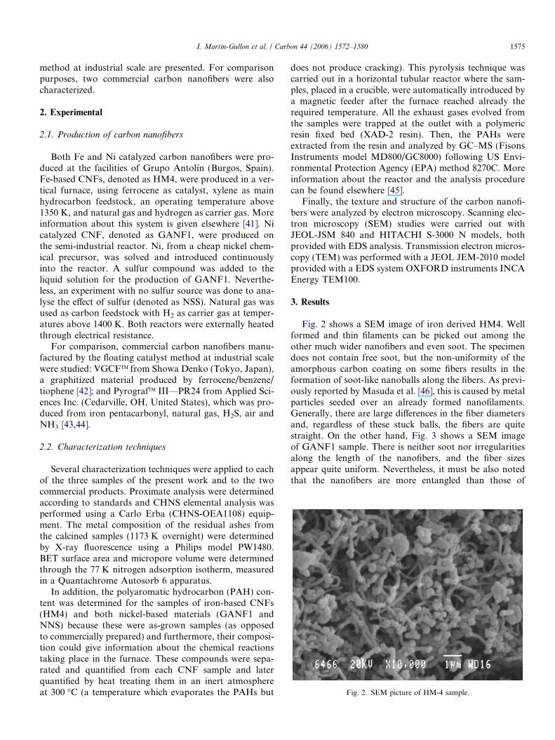
Fig. 2. SEM picture of HM-4 sample.
I. Martin-Gullon et al. / Carbon 44 (2006) 1572–1580 1575
method at industrial scale are presented. For comparisonpurposes, two commercial carbon nanofibers were alsocharacterized.
2. Experimental
2.1. Production of carbon nanofibers
Both Fe and Ni catalyzed carbon nanofibers were pro-duced at the facilities of Grupo Antolın (Burgos, Spain).Fe-based CNFs, denoted as HM4, were produced in a ver-tical furnace, using ferrocene as catalyst, xylene as mainhydrocarbon feedstock, an operating temperature above1350 K, and natural gas and hydrogen as carrier gas. Moreinformation about this system is given elsewhere [41]. Nicatalyzed CNF, denoted as GANF1, were produced onthe semi-industrial reactor. Ni, from a cheap nickel chem-ical precursor, was solved and introduced continuouslyinto the reactor. A sulfur compound was added to theliquid solution for the production of GANF1. Neverthe-less, an experiment with no sulfur source was done to ana-lyse the effect of sulfur (denoted as NSS). Natural gas wasused as carbon feedstock with H2 as carrier gas at temper-atures above 1400 K. Both reactors were externally heatedthrough electrical resistance.
For comparison, commercial carbon nanofibers manu-factured by the floating catalyst method at industrial scalewere studied: VGCFTM from Showa Denko (Tokyo, Japan),a graphitized material produced by ferrocene/benzene/tiophene [42]; and PyrografTM III—PR24 from Applied Sci-ences Inc. (Cedarville, OH, United States), which was pro-duced from iron pentacarbonyl, natural gas, H2S, air andNH3 [43,44].
2.2. Characterization techniques
Several characterization techniques were applied to eachof the three samples of the present work and to the twocommercial products. Proximate analysis were determinedaccording to standards and CHNS elemental analysis wasperformed using a Carlo Erba (CHNS-OEA1108) equip-ment. The metal composition of the residual ashes fromthe calcined samples (1173 K overnight) were determinedby X-ray fluorescence using a Philips model PW1480.BET surface area and micropore volume were determinedthrough the 77 K nitrogen adsorption isotherm, measuredin a Quantachrome Autosorb 6 apparatus.
In addition, the polyaromatic hydrocarbon (PAH) con-tent was determined for the samples of iron-based CNFs(HM4) and both nickel-based materials (GANF1 andNNS) because these were as-grown samples (as opposedto commercially prepared) and furthermore, their composi-tion could give information about the chemical reactionstaking place in the furnace. These compounds were sepa-rated and quantified from each CNF sample and laterquantified by heat treating them in an inert atmosphereat 300 �C (a temperature which evaporates the PAHs but
does not produce cracking). This pyrolysis technique wascarried out in a horizontal tubular reactor where the sam-ples, placed in a crucible, were automatically introduced bya magnetic feeder after the furnace reached already therequired temperature. All the exhaust gases evolved fromthe samples were trapped at the outlet with a polymericresin fixed bed (XAD-2 resin). Then, the PAHs wereextracted from the resin and analyzed by GC–MS (FisonsInstruments model MD800/GC8000) following US Envi-ronmental Protection Agency (EPA) method 8270C. Moreinformation about the reactor and the analysis procedurecan be found elsewhere [45].
Finally, the texture and structure of the carbon nanofi-bers were analyzed by electron microscopy. Scanning elec-tron microscopy (SEM) studies were carried out withJEOL-JSM 840 and HITACHI S-3000 N models, bothprovided with EDS analysis. Transmission electron micros-copy (TEM) was performed with a JEOL JEM-2010 modelprovided with a EDS system OXFORD instruments INCAEnergy TEM100.
3. Results
Fig. 2 shows a SEM image of iron derived HM4. Wellformed and thin filaments can be picked out among theother much wider nanofibers and even soot. The specimendoes not contain free soot, but the non-uniformity of theamorphous carbon coating on some fibers results in theformation of soot-like nanoballs along the fibers. As previ-ously reported by Masuda et al. [46], this is caused by metalparticles seeded over an already formed nanofilaments.Generally, there are large differences in the fiber diametersand, regardless of these stuck balls, the fibers are quitestraight. On the other hand, Fig. 3 shows a SEM imageof GANF1 sample. There is neither soot nor irregularitiesalong the length of the nanofibers, and the fiber sizesappear quite uniform. Nevertheless, it must be also notedthat the nanofibers are more entangled than those of

Fig. 3. SEM picture of GANF1 sample.
Fig. 4. TEM picture of HM-4 sample, a closer look to a individual fiber,with a clear different core and a thickened coating.
1576 I. Martin-Gullon et al. / Carbon 44 (2006) 1572–1580
HM4, although their aspect ratio is good. On the contrary,the NSS sample, produced in the same conditions asGANF1 but without a sulfur feedstock, yielded soot withsome isolated fibril structures. Thus, it can be pointedout that the sulfur is critical for the effect of producing car-bon nanofibers and inhibiting soot formation.
Table 1 contains the CHNS and proximate analysis aswell as other parameters. It is noted that the iron-basedmaterial has a very low ash content of 2%, whereas thisamount is higher for Ni-based GANF1 and NSS (13.5%and 8%, respectively). In relation to the commercial prod-ucts, Showa Denko has no ash content at all, which isindicative that the graphitization treatment volatilized allthe metal content. The ash content of Pyrograf III is closeto that of HM4 as well as both the proximate and ultimateanalysis (except for sulfur). X-ray fluorescence of the ashesindicated that the compositions of the ashes from HM4and Pyrograf III are 99.5% iron oxides, and those ofGANF1 are composed of NiO in a similar concentration,which is indicative of the original sulfur content of theashes (i.e. sulfides do not evolve into sulfates but areevolved as SO2 and quantified as S in the CHNS analysis).The amount of hydrogen in NNS (mostly soot) is very highand different from all the others. BET specific surface areafor GANF1 is higher than those of the other nanofibersstudied, as commented below.
TEM analysis shows large differences in the structures ofHM4 and GANF1. Fig. 4 shows a fiber of the HM4 sam-ple. The image clearly shows a small metal particle, that
Table 1Ultimate analysis, proximate analysis, ash, metal content, and BET specific su
Sample C (%) H (%) N (%) S (%
HM-4 95.7 0.3 0.0 0.0GANF1 84.1 0.5 0.9 0.9NNS 86.5 2.1 1.3 0.0SDK 99.9 0.0 0.0 0.0Pyrograf III 93.4 0.48 1.1 0.6
forms catalytically the core of the nanofiber consisting ofa bundle of MWNTs. This catalytic core is covered witha coating of amorphous carbon. Consequently, the low sur-face area of HM4 could be expected since the nanofibersare solid and the texture of the soot coating is non-porousand has short-length crystallinity.
Fig. 5 shows TEM images of different magnifications ofGANF1. From a general overview in Fig. 5a, it is clear thatthe pipe-type structure of these nanofibers with huge hol-low cores is completely different. In addition, it seems thatthe extremes of the nanofibers are opened and very few cat-alytic particles were detected. A higher magnification image(Fig. 5b) confirms the wide, hollow core structure andreveals a wide distribution of nanofiber diameters. Largemetal particles, which appear independent of the nanofi-bers, are also present in Fig. 5b. The structure of GANF1is stacked-cup nanofiber type for carbon nanofibers withboth large diameters (100 nm), as seen in Fig. 5c and d,and small diameters (40 nm), as seen in Fig. 5e with a bam-boo-type cone. It is very clear from Fig. 5a–e that all thefibrils are highly graphitic and there is no CVD thickening.These nanofibers exhibit clearly a cylindrical cross-section,as observed in Fig. 5f, which shows a nice perspective of thestructure.
The PAHs present in the as-grown products are shownin Table 2, and the compound distribution gives an idea
rface area of the carbon samples studied
) Ash (%) Metal (%) Surface (m2/g)
2.0 1.4 14.213.5 10.6 178.48.0 5.6 N/A0.0 0.0 18.02.1 1.4 41.9

Fig. 5. TEM pictures of GANF1. (a) and (b) general overview, with a clear hollow core, with no metal on the tips, (c) a wide CNF of over 100 nm ofdiameter, (d) the border of previous 100 nm diameter with stacked cup structure and no coating, (e) a 40 nm CNF with same structure and a bambooclosing and (f) a clear cylindrical cone form of the fibril.
I. Martin-Gullon et al. / Carbon 44 (2006) 1572–1580 1577
about how the gas-phase cracking reactions, which finallyyield soot or CVD coating, were taken place (PAHs areintermediates in the formation of soot). Table 2 showsthe 16 most toxic and harmful PAHs according to the
US-EPA. As expected, NSS contains multiple PAHs sinceit is primarily comprised of soot. It must be pointed outthat most of the PAHs have over three rings, especiallypyrene (1% concentration). Pyrene is considered to be the

Table 2PAH concentration on the as-grown materials studied, expressed inmilligrams of compound per kilogram of carbon sample
Compounds HM-4 GANF1 NNS
Naphthalene 90 700 110Acenaphthylene 175 1.6 340Acenaphthene 19 0.1 100Fluorene 3 0.1 170Phenanthrene 0 0.5 630Anthracene 45 0.3 6300Fluorantene 50 0.1 6400Pyrene 658 0.2 10 400Benzo[a]anthracene 0 1.1 130Chrysene 1 0.1 150Benzo[b+j+k]fluorantene 0 0.3 360Benzo[a]pyrene 0 0.6 720Indeno[1,2,3-cd]pyrene 0 0.1 110Dibenzo[a,h]anthracene 0 0.1 4.50Benzo[ghi]perilene 0 0.2 430
1578 I. Martin-Gullon et al. / Carbon 44 (2006) 1572–1580
precursor or initiator of homogeneous gas phase sootformation and its presence undoubtedly means thatamorphous carbon formation (free or thickening) is takingplace [47]. For HM4, which has a CVD coating and sootformation, pyrene is again the prevalent PAH, but in amuch lower concentration (658 mg/kg). Nevertheless,naphthalene is the only predominant PAH in GANF1, witha negligible amount of other compounds. There is a negligi-ble amount of the other PAHs. This aspect clearly indicatesthat the reaction includes no hydrocarbon cracking wheresoot formation is highly inhibited, a marked difference withrespect to NNS sample (run without sulfur feed).
In relation to the commercial fibers, Showa Denko car-bon nanofibers have a structure of thickened nanofibersbased on MWNT coating, which have been clearly graph-itized according to the TEM exploration (as published inthe product datasheet1). On the other hand, Pyrograf IIIhas a stacked-cup carbon nanofiber structure with a lightCVD coating. From TEM exploration, it can be said thatPyrograf III and the stacked-cup carbon nanofibers charac-terized by Endo et al. [23] have the same structure and, infact, both materials were produced using iron pentacar-bonyl, natural gas and hydrogen sulfide as a sulfur source.
4. Discussion
GANF1 carbon nanofibers yield a stacked cup structurewhen using natural gas as hydrocarbon feedstock. BothGANF1 and Pyrograf III share a similar graphene struc-ture with a wide hollow core except that GANF1 has noCVD coating resulting in a much higher surface area.While the type of catalyst (Fe vs Ni) does not seem impor-tant for producing this type of CNFs, the presence of sulfurseems to be indispensable to produce of this unique struc-ture. Kim et al. [24] suggested that the catalyst particlemust be molten, and according to Tibbetts et al. [38], the
1 http://www.sdkc.com/documents/VGCF-H.pdf.
presence of sulfur causes the catalyst particles to melt dueto an eutectic in the Fe–S system at 1271 K and at a42 at.% of S. This molten state increases the catalytic activ-ity, which allows to reduce the residence time considerablyand, in turn, mitigates the non-catalytic CVD coating (orsoot) formation. The quantity of sulfur in the feedstockcannot be random and must be on a similar atomic ratioto iron. Higher concentrations of sulfur have been reportedto cause a negative effect [37]. Metallic Ni has a very highmelting point of 1728 K, but the melting point of NiS isonly 1063 K and there is an eutectic point between Niand NiS at 908 K which corresponds to a 32 at.% of sulfurin the mixture [48]. Both eutectic and NiS melting pointsare lower than the operating temperature and, conse-quently, metallic nickel might be present in equilibriumwith a molten particle. Fig. 6a shows a TEM image of acatalytic particle that has grown a short nanofiber. Thisimage shows that the particle has a long shape, and the var-iable darkness suggests that the composition is not uniformacross the particle. EDS analysis of a magnified image(Fig. 6b) shows that the portion of the particle on the left(darker) is composed of only Ni, whereas the other side(lighter) is composed of S and Ni with a sulfur concentra-tion of 46.1 atomic %, which would be molten at reactionconditions. Other examples may confirm this feature. Itappears that the external portion of the catalytic particle,which adsorbs the hydrocarbon source, is elemental andsolid Ni, but it is not clear if (1) the fiber grew from thedark region of the particle formed by Ni (and not molten)while attaining its shape from the union with the moltenportion; or (2) the fiber began to grow from the moltenportion because of its special shape and, due to this feature,the stacked cup might have a circular cross-section. Ineither case, it must be stated that it is uncommon to findcatalytic particles at the tips of nanofibers like thoseobserved probably because they flow out of their moltenstate leaving only opened the hollow core. However, inthose nanofibers containing catalytic particles, which arescarce, a carbon layer always surrounds the particle asshown in Fig. 6b, which prevents any possible fluid fromflowing out.
As a consequence, it seems that the catalytic activity ofthe metal is related to sulfur through the formation of amolten state, which has also been shown to occur withphosphorous [49]. The combination of methane (naturalgas) and sulfur yields this unique stacked-cup structurefrom a partially molten particle regardless of the catalyst(Fe, Ni or Co) [50]. Nevertheless, sulfur has always beenconsidered to be poisonous for the metal transition catalyst(i.e. sulfur coverage and particle breakage prevent hydro-cracking reactions from occurring) [51]. When producingcarbon nanofibers at much higher temperatures, the sulfurcontinues to have a negative effect since the elemental formof metal, not the sulfide, is critical to the reaction. How-ever, a critical amount of sulfur may have benefits as anagent for partially melting the particle and preventingsintering.

Fig. 6. TEM pictures of GANF1 fibril with a metal on the tip at two different magnifications.
I. Martin-Gullon et al. / Carbon 44 (2006) 1572–1580 1579
The present work shows that thickened nanofibers witha MWNT core can be produced from an aromatic feed-stock with and without the presence of sulfur (ShowaDenko is produced with tiophene; HM4 is produced with-out sulfur). In addition, the sulfur precursor type was pre-viously reported to be independent of sulfur’s effect onfloating catalyst production systems [52]. The present workalso confirms that stacked-cup structure is formed whenusing the same catalyst and sulfur with simpler carbonsources, such as methane (natural gas), like occurred withPyrograf III. Similar results were reported by Otsukaet al. [53], where methane and n-hexane yielded fishbonenanofibers whereas benzene and cyclopentadiene yieldedMWNTs.
5. Conclusions
1. Highly graphitic, stacked-cup-type carbon nanofiberswithout amorphous carbon coatings were obtained from afeedstock of natural gas and inexpensive nickel precursorby the floating catalyst method. The presence of sulfur iscritical to form the appropriate active catalyst particles,which appear to be partially molten on one side. This mol-ten state is responsible for yielding the stacked-cupstructure.
2. Thickened carbon nanofibers with MWNT bundleson the core of the filament are produced when using xyleneas a carbon source and ferrocene as a catalyst.
3. These results, and those previously reported, lead tothe conclusion that methane (natural gas) with the presenceof sulfur at high temperatures yields a stacked-cup nanofi-ber structure regardless of the metal catalyst (Fe, Ni andCo). Furthermore, the same carbon feedstock without sul-fur can yield other nanofiber structures at lower tempera-tures (platelet, fishbone and ribbon), but the influence ofthe metal catalyst is more important in this case.
4. Regardless of the presence of sulfur and the metal nat-ure, a feedstock of an aromatic compound or acetylene willform a MWNT structure. The intermediate chemical com-plex that forms over the metallic particle, which is similarfor both acetylene and an aromatic compound, probably
yields the MWNT structure, whereas the complex formedfrom methane (or other linear hydrocarbons) feedstock isdifferent and yields carbon fibrils of other structures.
Acknowledgements
The authors greatly appreciate the courtesy of Mr.Brock Marrs, from the University of Kentucky-Centerfor Applied Energy Research, in his valued help for thepreparation of the manuscript.
References
[1] Hughes TV, Chambers, CR. Manufacture of carbon filaments. USPatent 405480, 1889.
[2] Oberlin A, Endo M, Koyama T. Filamentous growth of carbonthrough benzene. J Crystal Growth 1976;32(3):335–49.
[3] Baker RTK, Barber MA, Harris PS, Feates FS, Waite RJ. Nucleationand growth of carbon deposits from the nickel catalyzed decompo-sition of acetylene. J Catal 1972;26(1):51–62.
[4] Endo M, Koyama T. Preparation of carbon fiber by vapor phasemethod. Japanese Patent 58-180615, 1983.
[5] Ijima S. Helical microtubules of graphitic carbon. Nature 1991;354:56–8.
[6] Park C, Anderson PE, Chambers A, Tan CD, Hidalgo R, RodriguezNM. Further studies of the interaction of hydrogen with graphitenanofibers. J Phys Chem B 1999;103:10572–81.
[7] Chambers A, Nemes T, Rodriguez NM, Baker RTK. Catalyticbehavior of graphite nanofiber supported nickel particles. 1. Com-parison with other support media. J Phys Chem B 1998;102:2251–8.
[8] Fan SS, Chapline MG, Franklin NR, Tombler TW, Castell AM, DaiH. Self-oriented regular arrays of carbon nanotubes and their fieldemission properties. Science 1999;283:512–4.
[9] Grobert N, Hsu WK, Zhu YQ, Hare JP, Kroto HW, Walton DMR,et al. Enhanced magnetic coercivities in Fe nanowires. Appl PhysLett 1999;75(21):3363–5.
[10] Andrews R, Jacques D, Ninot M, Rantell T. Fabrication of carbonmultiwall nanotube/polymer composites by shear mixing. MacromolMater Eng 2002;287:395–403.
[11] Tibbetts GG, McHugh JJ. Mechanical properties of vapor-growncarbon fiber composites with thermoplastic matrices. J Mater Res1999;14(7):2871–80.
[12] Zheng GB, Kouda K, Sano H, Uchiyama Y, Shi YF, Quan HJ. Amodel for the structure and growth of carbon nanofibers synthetizedby the CVD method using nickel as catalyst. Carbon 2004;42:635–40.
1580 I. Martin-Gullon et al. / Carbon 44 (2006) 1572–1580
[13] Mukhopadhyay K, Porwal D, Lal D, Ram K, Mathur GN. Synthesisof coiled/straight carbon nanofibers by catalytic chemical vapordeposition. Carbon 2004;42:3254–6.
[14] Rodriguez NM, Chambers A, Baker RTK. Catalytic engineering ofcarbon nanostructures. Langmuir 1995;11:3862.
[15] Carneiro OC, Rodriguez NM, Baker RTK. Growth of carbonnanofibers from iron–copper catalyzed decomposition of CO/C2H4/H2 mixtures. Carbon 2005;43:2389–96.
[16] Helveg S, Lopez-Cartes C, Sehested J, Hansen PL, Clausen BS,Rostrup-Nielsen JR, et al. Atomic-scale imaging of carbon nanofibregrowth. Nature 2004;427:426–9.
[17] Tanaka A, Yoon SH, Mochida I. Preparation of highly crystalline onFe and Fe–Ni catalyst with a variety of graphene plate alignments.Carbon 2004;42(3):591–7.
[18] Krishnankutty N, Park C, Rodriguez NM, Baker RTK. The effect ofcopper on the structural characteristics of carbon filaments producedfrom iron catalyzed decomposition of ethylene. Catal Today 1997;37:295–307.
[19] Winter F, Bezemer GL, van der Spek C, Meeldijk JD, van Dillen AJ,Geus JW, et al. TEM and XPS studies to reveal the presence ofcobalt and palladium particles in the inner core of carbon nanofibers.Carbon 2005;43:327–32.
[20] Nolan PE, Lynch DC, Cutler AH. Carbon deposition and hydrocar-bon formation on group VIII metal catalyst. J Phys Chem B 1998;102:4165–75.
[21] Yoon SH, Lim S, Hong SH, Qiao W, Whitehurst DD, Mochida I,et al. A conceptual model for the structure of catalytically growncarbon nanofibers. Carbon 2005;43:1828–38.
[22] Terrones H, Hayashi T, Munoz-Navia M, Terrones M, Kim YA,Grobert N, et al. Chem Phys Lett 2001;343:241–50.
[23] Endo M, Kim YA, Hayash T, Fukai Y, Oshida K, Terrones M, et al.Structural characterization of cup-stacked-type nanofibers with anentirely hollow core. Appl Phys Lett 2002;80(7):1267–9.
[24] Kim YA, Hayashi T, Naokama S, Yanagisawa T, Endo M.Comparative study of herringbone and stacked-cup carbon nanofi-bers. Carbon 2005;43:3005–8.
[25] Endo M, Takeuchi K, Kobori K, Takahashi K, Kroto HW, SarkarA. Pyrolitic carbon nanotubes from vapor-grown carbon fibers.Carbon 1995;33(7):873–81.
[26] Tibbetts GG. Vapor-grown carbon fibers: status and prospects.Carbon 1989;27(5):745–7.
[27] Tibbetts GG. Lengths of carbon fibers grown from iron catalystparticles in natural gas. J Crystal Growth 1985;73:431–8.
[28] Park C, Keane MA. Catalyst support effects in the growth ofstructured carbon from the descomposition of ethylene over nickel.J Catal 2004;221:386–99.
[29] Le QT, Schouler MC, Garden J, Gadelle P. Fe(NO3)3 Æ 9H2O andFe3(CO)12 as catalyst precursors for the elaboration of VGCF: SEMand TEM study-improvement of the process. Carbon 1999;37:505–14.
[30] Toebes ML, Bitter JH, van Dillen AJ, de Jong KP. Impact of thestructure and reactivity of nickel particles on the catalytic growth ofcarbon nanofibers. Catal Today 2002;76:33–42.
[31] Mukai SR, Matsuda T, Matsuzawa Y, Hashimoto K. The influenceof catalyst particle size distribution on the yield of vapor-growncarbon fibers produced by the liquid pulse injection technique. ChemEng Sci 1998;53:439–48.
[32] Hoque A, Alam MK, Tibbetts GG. Synthesis of a catalyst particles ina vapor grown carbon fiber reactor. Chem Eng Sci 2001;56:4233–43.
[33] Endo M, Kim YA, Fukai Y, Hatashi T, Terrones M, Terrones H,et al. Comparison of semi-crystalline and highly crystalline multi-walled carbon nanotubes. Appl Phys Lett 2001;79(10):1531–3.
[34] Andrews R, Jacques D, Rao AM, Derbyshire F, Qian D, Fan X,et al. Continuous production of aligned carbon nanotubes: a stepcloser to commercial realization. Chem Phys Lett 1999;303:467–74.
[35] Kamalakaran R, Terrones M, Seeger T, Kohler-Redlich P, Ruhle M,Kim YA, et al. Synthesis of thick and crystalline nanotube arrays byspray pyrolysis. Appl Phys Lett 2000;77(1):3385–7.
[36] Lee CJ, Lyu SC, Kim HW, Park CY, Yang CW. Large-scaleproduction of aligned carbon nanotubes by vapor phase growthmethod. Chem Phys Lett 2002;359:109–14.
[37] Ci L, Li Y, Wei B, Liang J, Xu C, Wu D. Preparation of carbonnanofibers by the floating catalyst method. Carbon 2000;38:1933–7.
[38] Tibbetts GG, Bernardo CA, Gorkiewicz DW, Alig RL. Role of sulfurin the production of carbon fibers in the vapor phase. Carbon 1994;32:569–73.
[39] Tibbetts GG, Balogh MP. Increase in yield of carbon fibers grownabove iron/carbon eutectic. Carbon 1999;37(2):241–7.
[40] Ren WC, Heng HM. Herringbone-type carbon nanofibers with asmall diameter and a large hollow core synthesized by catalyticdecomposition of methane. Carbon 2002;41:1645–87.
[41] Merino C, Ruiz G, Soto P, Melgar A, Martın EM, Gomez de SalazarJM. Influence of the carbon source on the formation of carbonnanofibres for polymer reinforcement. Extended Abstracts on CD,Carbon’03. Oviedo (Spain), Spanish Carbon Group, 2003.
[42] Morita T, Yamamoto R, Higashi T, Tsuji K. Fine carbon fiber andmethod for producing the same. US Patent Application PublicationUS2004/0166048 A1, 2004.
[43] Tibbetts GG, Kwag C, Glasgow DG, Lake ML. Volume andcomposite resistivities of carbon nanofibers. Extended Abstracts onCD, Carbon’03. Oviedo (Spain); Spanish Carbon Group, 2003.
[44] Tibbetts GG. Manufacturing and properties of vapor grown carbonnanofibers. Abstract from Vapor Grown Carbon Nanofiber Materialsand Applications Workshop (Kettering, Ohio, USA), 2004.
[45] Jauhiainen J, Martin-Gullon I, Conesa JA, Font R. Emissions frompyrolysis and combustion of olive oil solid waste. J Anal Appl Pyrol2005;74:512–7.
[46] Masuda T, Mukai SR, Hashimoto K. The liquid pulse injectiontechnique: a new method to obtain long vapor grown carbon fibers athigh growth rates. Carbon 1993;31(5):783–7.
[47] Kazakov A, Wang H, Frenklach M. Detailed modeling of sootformation in laminar premixed ethylene flames at a pressure of10 bar. Combust Flame 1995;100:111–20.
[48] Baker H, editor. Alloy Phase Diagrams. ASM Handbook, vol.3. Materials Park, Ohio, USA: ASM International (The MaterialsInformation Society); 1992.
[49] Benissad-Aissani F, Aıt-Amar H, Schouler MC, Gadelle P. The roleof phosphorous in the growth of vapor-grown carbon fibres obteinedby catalytic decomposition of hydrocarbons. Carbon 2004;42:2163–8.
[50] Singh C, Quested T, Boothroyd CB, Thomas P, Kinloch IA, Abou-Kandi AI, et al. Synthesis and characterization of carbon nanofibersproduced by the floating catalyst method. J Phys Chem B 2002;106:10915–22.
[51] Kim MS, Rodriguez NM, Baker RTK. The interplay between sulfuradsorption and carbon deposition on cobalt catalyst. J Catal 1993;143:449–63.
[52] Kato K, Kusakabe K, Morooka S. Effect of sulphur on vapor growncarbon fiber. J Mater Sci Lett 1994;13:374–7.
[53] Otsuka K, Abe Y, Kanai N, Kobayashi Y, Yakenaka S, Tanabe E.Synthesis of carbon nanotubes on Ni/carbon fiber catalysts undermild conditions. Carbon 2004;42:727–36.