Promoting effect of fluorine on cobalt—molybdenum/ titania hydrodesulfurization catalysts
3764r 2010 American Chemical Society pubs.acs.org/EF
Energy Fuels 2010, 24, 3764–3771 : DOI:10.1021/ef901368wPublished on Web 02/16/2010
Novel Micro- and Mesoporous Composite Molecular Sieve Assembled by Zeolite L
Nanocrystal and Its Performance for the Hydrodesulfurization (HDS) of FluidCatalytic Cracking (FCC) Gasoline
†
Quan Huo,‡,§ Yanjun Gong,‡,§ Tao Dou,*,‡,§ Zhen Zhao,*,‡,§ Huifang Pan,§ and Feng Deng )
‡State Key Laboratory of Heavy Oil Processing, and §The Key Laboratory of Catalysis, China National Petroleum Corporation,China University of Petroleum, Beijing 102249, People’s Republic of China, and )Wuhan Institute of Physics and Mathematics,
Chinese Academy of Sciences, Wuhan 430071, People’s Republic of China
Received November 14, 2009. Revised Manuscript Received February 3, 2010
Anovelmicro- andmesoporous compositemolecular sieve (denoted as LMC)was synthesized by using thenanocrystal clusters of zeolite L as the precursor and a cation surfactant cetyltrimethylammoniumbromide(CTAB) as the template. The physicochemical properties of samples were characterized bymeans of X-raydiffraction (XRD), nitrogen-adsorption isotherms, scanning electron microscopy (SEM), transmissionelectronmicroscopy (TEM), 27Al and 29Simagic angle spinning nuclearmagnetic resonance (MASNMR),Fourier transform infrared spectroscopy (FTIR), andFourier transform infrared spectroscopy of pyridineadsorption (Py-FTIR). The results showed that composite molecular sieve LMC was synthesized by theself-assembly of zeolite Lnanocrystal clusters under the template effect ofCTAB. In addition, surface area,pore volume, and pore size of LMC significantly increased in comparison to those of conventionalmicroporous zeolite L. The results measured by Py-FTIR showed that LMC had an appropriate acidamount and acid distribution. For evaluation of fluid catalytic cracking (FCC) gasoline hydro-desulfurization (HDS), the catalyst that introduced material LMC exhibited the excellent performancesof desulfurization, isomerization, aromatization, olefin retention, andpreserving the researchoctane number(RON) value compared to the catalyst that introduced ordinary microporous zeolite L or mesoporousAl-MCM-41 and used bare alumina as the support. The excellent catalytic performances of the catalystshould be attributed to the appropriate acidity distribution and open pore structure of material LMC.
1. Introduction
Currently, hydrodesulfurization (HDS) has become a con-cerned topic because of the severe legislation on limiting thesulfur content in gasoline. The sulfur content is expected to belowered to a 10-50 ppm level in most countries.1,2 It has beenreported that more than 90% of sulfur-containing com-pounds in typical refinery gasoline pools come from fluidcatalytic cracking (FCC) gasoline.3 For this reason, it hasbecome a focal point to efficiently remove the sulfur com-pounds in the FCC gasoline. In fact, it is easy for a conven-tional HDS catalyst using Al2O3 as the support to obtainultra-low sulfur gasoline under severe operation conditions.However, the central issue of FCC gasoline HDS is not onlydesulfurization but also preserving the research octane num-ber (RON) of hydrogenated gasoline.For thismultifunctionalpurpose, it is difficult for the conventional HDS catalystto gain such a catalytic performance. Some results in the
literature4,5 show that the addition of the acidic component ofzeolites in catalysts canpromote the desulfurization activity ofthe HDS catalyst. Similar to a member of microporouszeolites, zeolite L is also considered as the additives of thesupport for such a catalyst system because of its selectivehydrogenation performance6 and excellent activities forHDS,7 isomerization, and aromatization.8 However, themajor drawback of zeolite L, resembling some other micro-porous zeolites, is the limited size of the pore channels(<1 nm). This hinders the diffusion of larger moleculescontaining sulfur in zeolite pores. Furthermore, the excessivestrong acid sites in zeolite can also result in lower hydro-isomerization selectivity because of a higher cracking acti-vity,9,10 causing the reduction in the liquid product yield.Thanks to the large pore size (2-50 nm) and weak acidproperty, a mesoporous molecular sieve may compensatefor the disadvantages of microporous zeolites. Therefore,the micro- and mesoporous composite molecular sieves com-binedwith the advantages of zeolite andmesoporousmaterial,used as the support of the HDS catalyst, are worthy to beconsidered and studied.
†This paper has been designated for the Asia Pacific Conference onSustainable Energy and Environmental Technologies (APCSEET) specialsection.
*To whom correspondence should be addressed. Telephone: þ8610-89733235. Fax: þ8610-89734979. E-mail: [email protected] (T.D.);[email protected] (Z.Z.).(1) Song, C. Catal. Today 2003, 86, 211–263.(2) Babich, I. V.; Moulijn, J. A. Fuel 2003, 82, 607–631.(3) Brunet, S.; Mey, D.; Perot, G.; Bouchy, C.; Diehl, F.Appl. Catal.,
A 2005, 278, 143–172.(4) Isoda, T.; Nagao, S.; Ma, X. L.; Korai, Y.; Mochida, I. Energy
Fuels 1996, 10, 1078–1082.(5) Bataille, F.; Lemberton, J. L.; Perot, G.; Leyrit, P.; Cseri, T.;
Marchal, N.; Kasztelan, S. Appl. Catal., A 2001, 220, 191–205.
(6) Alvarez-Rodriguez, J.; Guerrero-Ruiz, A.; Rodriguez-Ramos, I.;Arcoya-Martin, A. Catal. Today 2005, 107-108, 302–309.
(7) Taniguchi, M.; Imamura, D.; Ishige, H.; Ishii, Y.; Murata, T.;Hidai, M.; Tatsumi, T. J. Catal. 1999, 187, 139–150.
(8) Trakarnroek, S.; Jongpatiwut, S.; Rirksomboon, T.; Osuwan, S.;Resasco, D. E. Appl. Catal., A 2006, 313, 189–199.
(9) Lucas, A.; Valverde, J. L.; Sanchez, P.; Dorado, F.; Ramos, M. J.Appl. Catal., A 2005, 282, 15–24.
(10) Lugstein,A.; Jentys,A.; Vinek,H.Appl. Catal., A 1999, 176, 119–128.

3765
Energy Fuels 2010, 24, 3764–3771 : DOI:10.1021/ef901368w Huo et al.
In the past decade, significant efforts have been devoted todeveloping strategies for the synthesis of micro- and meso-porous composite materials,11-15 which compensate for thedrawbacks of small pore size for microporous zeolite andweak acid property and poor hydrothermal stability formesoporousmaterial. Somehighlighted results involving suchmaterial have also been continually reported in some litera-ture.16-18Meso- andmicroporous compositematerials can besynthesized by partial crystallization of the amorphous porewall of preformed mesoporous material. By this strategy,MCM-41/ZSM-5 composites were reported by Huanget al.19 Through a process of two-step crystallization, meso-porous MCM-41 was first synthesized and, subsequently, astructure-directing agent, tetrapropylammonium bromide,was exchanged into the MCM-41 pore wall through a pre-treatment process. Thus, the amorphouswall ofMCM-41wasrecrystallized. The resulting material was more advantageousthan amorphousMCM-41 in acid catalysis.Meso- andmicro-porous composite materials can also be synthesized by theself-assembly of the zeolite seed. Pinnavaia’s group17,18 repor-ted the synthesis of hexagonal Al-MSU-S via self-assembly ofthe zeolite seeds. The synthesized composites exhibited veryhigh hydrothermal stability. Later, Xiao et al.20 also reportedordered mesoporous aluminosilicate MAS-3 and MAS-8synthesized from preformed zeolite L precursors containingthe building unit of zeolite L and using cetyltrimethylammo-nium bromide (CTAB) and Pluronic P123 as templates,respectively. Catalytic activity results in cracking cumeneshowed that MAS-3 and MAS-8 were more active thanAl-MCM-41. In addition, micro- and mesoporous compositematerials can also be prepared by solid template, such ascarbon materials,21-23 biological templates,24 and polymer.25
The mesopores are created by the removal of the embeddedcarbon or organic matrix in zeolite. As post-treatmentmethods, the formation of mesopores in zeolite materials maybe obtained by desilication,26 steaming,27 or acid leaching.28
Apparently, a lot of research works of micro- and meso-porous compositematerials related to zeoliteY, ZSM-5, Beta,and mordenite have been continuously reported. However,the report concerning mesoporous zeolite L is extremelyscarce. Possibly, it is because the synthesis of meso- andmicroporous composite L molecular sieves is very difficult.It can only be successfully carried out in the narrow phaseregion. In the present work, we first report a novel micro- andmesoporous composite molecular sieve prepared by the self-assembly of zeolite L nanocrystal clusters in the presence oftemplate CTAB. In addition, we introduced the material tothe support of the catalyst for the HDS of full-range FCCgasoline. The catalytic multifunction performances, includingHDS and RON preservation of the catalysts containing themicro- andmesoporous zeolite Lmaterials, were investigated,and the supermultifunction performances were obtained overthese catalysts. This work may provide a new approach tosolve the contradictory problem between the deep desulfuri-zation and RON preservation in the process of the HDS ofFCC gasoline.
2. Experimental Section
2.1. Synthesis of LMC. 2.1.1. Preparation of Zeolite Nano-crystal Clusters. According to the report in the literature,17
zeolite nanocrystal clusters can be prepared by shortening thecrystallization time for perfect zeolite in the synthesis process ofzeolite. From this, zeolite L nanocrystal clusters were firstprepared with the gel composition of 1.0 SiO2/0.1 Al2O3/0.15K2O/25 H2O. A silica-alumina microsphere (Fushun CatalystCompany, 69.4% SiO2 and 11.8% Al2O3) as the silica andalumina sources was mixed with an aqueous solution of KOH(Beijing Chemical Company, 82%). In addition, the mixturewas homogenized by stirring for 1 h, followed by transferringthe mixture into an autoclave for crystallization at 150 �C for acertain time. Then, the product was cooled to room tempera-ture. The zeolite L nanocrystal clusters were first obtained andused as the precursor for the synthesis of LMC.
2.1.2. Synthesis of LMC. LMC was synthesized as follows:First, 2.7 g of CTAB was dissolved into 72.6 g of H2O understirring. Second, 15 g of zeolite L nanocrystal clusters was slowlyadded into the solution of CTABwith vigorous stirring, and thepH value of the synthesis system was adjusted to 9.6 by 5 wt %HCl aqueous solution. Then, the homogenized mixture wastransferred into a Teflon-lined autoclave for additional crystal-lization at 100 �C for 48 h. The final product was collected byfiltration, washed with distilled water, dried at 100 �C for 4 h,and calcined at 550 �C for 6 h to remove the surfactant CTAB.
2.2. Catalyst Preparation. First, zeolite L, LMC, mesoporousMCM-41, and the mechanical mixture of zeolite L and MCM-41 were separately added to the supports of the catalysts byphysical mixing, to partially substitute γ-alumina support.Second, the different supports were prepared by the extrusionmethod using different molecular sieves as additives and 70 wt%pseudo-boehmite (Aluminum Corporation of China Limi-ted, 69.5%) as the binder. Then, the extruded sticks (1.5 mm �0.5-1 cm) were dried at 110 �C overnight and calcined at 550 �Cfor 4 h in air. Finally, the supports were impregnated by the two-step incipient-wetness impregnation method using ammoniummolybdate and cobalt nitrate as starting materials of activecomponents. After each impregnation step, the samples weredried at 110 �C for 6 h and calcined at 550 �C for 4 h in air. All ofthe samples were also prepared with the proper amounts of Moand Co (corresponding to 16.5 wt%MoO3 and 3.5 wt% CoO).In addition, all of the catalysts were obtained by crushing intoparticles, with the grain size of 0.3-0.5 mm. The catalyst usingbare alumina as the support was taken as a reference sample.The compositions of different catalysts are listed in Table 1.
(11) Kustova, M. Y.; Kustov, A. L.; Christensen, C. H. Stud. Surf.Sci. Catal. 2005, 158, 255–262.(12) Tao, Y.; Kanoh, H.; Kaneko, K. J. Am. Chem. Soc. 2003, 125,
6044–6045.(13) Liu, Y.; Pinnavaia, T. J. Chem. Mater. 2002, 14, 3–5.(14) Wei, X.; Smirniotis, P. G.MicroporousMesoporousMater. 2006,
89, 170–178.(15) Wang, H.; Pinnavaia, T. J. Angew. Chem., Int. Ed. 2006, 45,
7603–7606.(16) Kloetstra, K. R.; Zandbergen,H.W.; Jansen, J. C.; van Bekkum,
H. Microporous Mesoporous Mater. 1996, 6, 287–293.(17) Liu, Y.; Zhang,W.; Pinnavaia, T. J. J. Am. Chem. Soc. 2000, 122,
8791–8792.(18) Liu, Y.; Zhang, W.; Pinnavaia, T. J. J. Angew. Chem., Int. Ed.
2001, 40, 1255–1258.(19) Huang, L.; Guo, W.; Deng, P.; Xue, Z.; Li, Q. J. Phys. Chem. B
2000, 104, 2817–2823.(20) Di,Y.;Yu,Y.; Sun,Y.;Yang,X.; Lin, S.; Zhang,M.; Li, S.;Xiao,
F.-S. Microporous Mesoporous Mater. 2003, 62, 221–228.(21) Boisen, A.; Schmidt, I.; Carlsson, A.; Dahl, S.; Brorson, M.;
Jacobsen, C. J. H. Chem. Commun. 2003, 958–959.(22) Janssen, A. H.; Schmidt, I.; Jacobsen, C. J. H.; Koster, A. J.;
Jong, K. P. Microporous Mesoporous Mater. 2003, 65, 59–75.(23) Tao, Y.; Kanoh, H.; Kaneko, K. J. Phys. Chem. B 2003, 107,
10974–10976.(24) Davis, S. A.; Burkett, S. L.; Mendelson, N. H.; Mann, S.Nature
1997, 385, 420–423.(25) Xiao, F.-S.; Wang, L.; Yin, C.; Lin, K.; Di, Y.; Li, J.; Xu, R.; Su,
D. S.; Schl€ogl, R.; Yokoi, T.; Tatsumi, T. Angew. Chem., Int. Ed. 2006,45, 3090–3093.(26) Groen, J. C.; Abello, S.; Villaescusa, L. A.; Perez-Ramirez, J.
Microporous Mesoporous Mater. 2008, 114, 93–102.(27) Boveri, M.; M�arquez-�Alvarez, C.; Laborde, M. �A.; Sastre, E.
Catal. Today 2006, 114, 217–225.(28) Chung, K. H.Microporous Mesoporous Mater. 2008, 111, 544–550.
3766
Energy Fuels 2010, 24, 3764–3771 : DOI:10.1021/ef901368w Huo et al.
2.3. Characterization of the Catalysts. X-ray diffraction(XRD) patterns of the samples were recorded in a ShimadzuX-6000 diffractometer using Cu KR radiation. The photo-graphs of samples were taken by transmission electronmicroscopy (TEM) and scanning electron microscopy (SEM)analyses, which were performed using FEI-QUANTA 200Fand JEOL JEM-2100 equipment, respectively. The surfacearea and pore size distribution of the samples were measuredby nitrogen isotherms using a Micromeritics ASAP 2010system. The pore size distributions for meso- and microporeswere calculated using the Barrett-Joyner-Halenda (BJH)and Horvath-Kawazoe (HK) models, respectively. Solid-state 27Al and 29Si magic angle spinning nuclear magneticresonance (MAS NMR) was performed in a Bruker Advance400 MHz spectrometer. IR spectra of the samples were re-corded on a Fourier transform infrared spectroscopy (FTIR)spectrometer using a MAGNA-IR 560 system. Surface acidamounts and types of samples were obtained by Fourier trans-form infrared spectroscopy of pyridine adsorption (Py-FTIR)on a MAGNAIR 560 FTIR instrument with a resolutionof 1 cm-1.
2.4. Catalytic Activity Measurement. The feedstock used inthis paper is Lanzhou full-range FCC gasoline, the propertiesof which are shown in Table 2. Catalytic performances wereinvestigated in a high-pressure fixed-bed reactor with 2.0 g ofcatalyst. All of the catalysts were presulfided for 4 h with a2 wt % CS2-cyclohexane mixture under the conditions ofliquid hourly space velocity (LHSV) of 1.0 h-1, temperature of320 �C, total pressure of 2.5 MPa, and an H2/cyclohexaneratio of 300. HDS tests were carried out under the conditionsof 270 �C, 2.0 MPa, H2/oil ratio of 200, and weight hourlyspace velocity (WHSV) of 2.0 h-1. Catalytic activities weremeasured at steady state after 20 h on stream. The sulfurcontent of gasoline after hydrotreatment was obtained by aLC-4-type Kulun sulfur analyzer. The group compositions ofgasoline were examined by a Beifen 3420 gas chromatographinstalled with a PONA capillary column (50 m� 0.2 mm). Thecomponents were identified in a PONA library and classifiedas n-paraffins, i-paraffins, olefins, naphthenes, and aromaticsby the data-processing software GC99. The software wassupplied by the Research Institute of Petroleum Processing(RIPP), China Petroleum and Chemical Corporation(SINOPEC). Meanwhile, the RON value of gasoline can becalculated on the basis of the percent contents and octanenumbers of the identifying components by the softwareGC99.
3. Results and Discussion
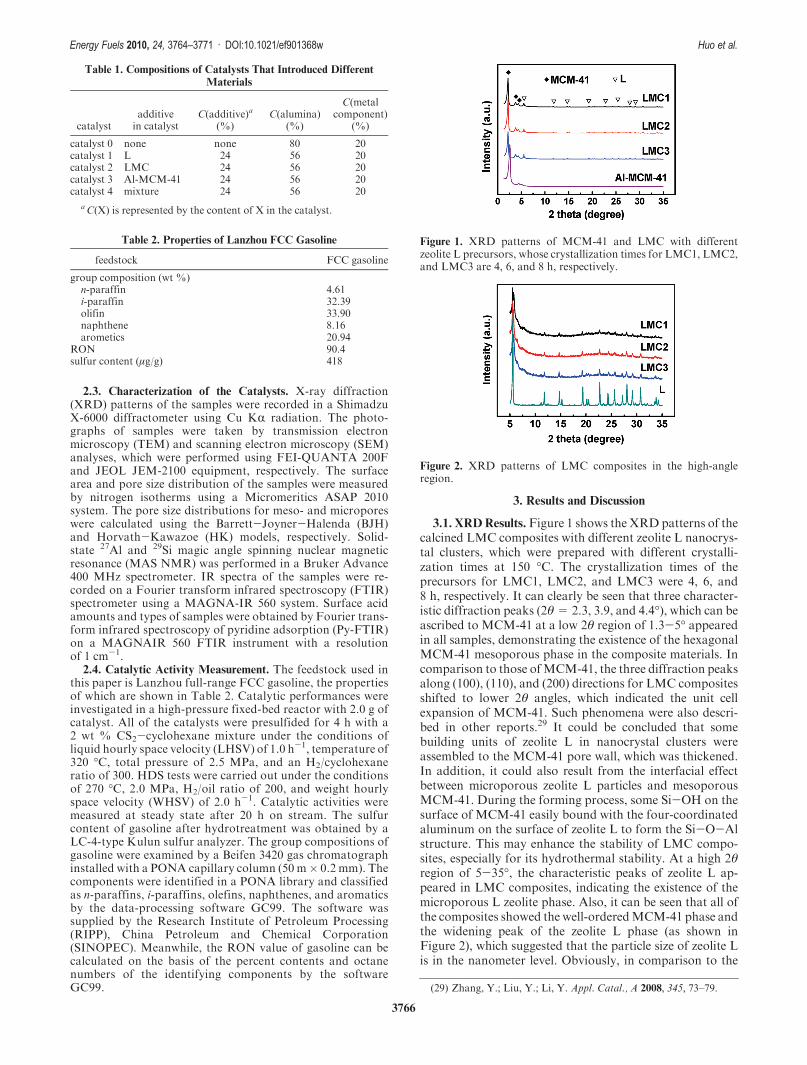
3.1. XRDResults. Figure 1 shows the XRDpatterns of thecalcined LMC composites with different zeolite L nanocrys-tal clusters, which were prepared with different crystalli-zation times at 150 �C. The crystallization times of theprecursors for LMC1, LMC2, and LMC3 were 4, 6, and8 h, respectively. It can clearly be seen that three character-istic diffraction peaks (2θ=2.3, 3.9, and 4.4�), which can beascribed to MCM-41 at a low 2θ region of 1.3-5� appearedin all samples, demonstrating the existence of the hexagonalMCM-41 mesoporous phase in the composite materials. Incomparison to those ofMCM-41, the three diffraction peaksalong (100), (110), and (200) directions for LMC compositesshifted to lower 2θ angles, which indicated the unit cellexpansion of MCM-41. Such phenomena were also descri-bed in other reports.29 It could be concluded that somebuilding units of zeolite L in nanocrystal clusters wereassembled to the MCM-41 pore wall, which was thickened.In addition, it could also result from the interfacial effectbetween microporous zeolite L particles and mesoporousMCM-41. During the forming process, some Si-OH on thesurface of MCM-41 easily bound with the four-coordinatedaluminum on the surface of zeolite L to form the Si-O-Alstructure. This may enhance the stability of LMC compo-sites, especially for its hydrothermal stability. At a high 2θregion of 5-35�, the characteristic peaks of zeolite L ap-peared in LMC composites, indicating the existence of themicroporous L zeolite phase. Also, it can be seen that all ofthe composites showed the well-orderedMCM-41 phase andthe widening peak of the zeolite L phase (as shown inFigure 2), which suggested that the particle size of zeolite Lis in the nanometer level. Obviously, in comparison to the
Table 1. Compositions of Catalysts That Introduced Different
Materials
catalystadditivein catalyst
C(additive)a
(%)C(alumina)
(%)
C(metalcomponent)
(%)
catalyst 0 none none 80 20catalyst 1 L 24 56 20catalyst 2 LMC 24 56 20catalyst 3 Al-MCM-41 24 56 20catalyst 4 mixture 24 56 20
a C(X) is represented by the content of X in the catalyst.
Table 2. Properties of Lanzhou FCC Gasoline
feedstock FCC gasoline
group composition (wt %)n-paraffin 4.61i-paraffin 32.39olifin 33.90naphthene 8.16arometics 20.94
RON 90.4sulfur content (μg/g) 418
Figure 1. XRD patterns of MCM-41 and LMC with differentzeolite L precursors, whose crystallization times for LMC1, LMC2,and LMC3 are 4, 6, and 8 h, respectively.
Figure 2. XRD patterns of LMC composites in the high-angleregion.
(29) Zhang, Y.; Liu, Y.; Li, Y. Appl. Catal., A 2008, 345, 73–79.

3767
Energy Fuels 2010, 24, 3764–3771 : DOI:10.1021/ef901368w Huo et al.
crystallinity of the ordinary zeolite L, that of zeolite L inLMC decreased. It suggested that the introduction of CTABhas an effect on the crystal growth of zeolite L. By calculationusing the Scherrer equation, the particle sizes of the zeolite Lnanocrystal in LMC1, LMC2, and LMC3 are about 10, 15,and 30 nm, respectively. Among three composites, thecomposite of LMC2 with the precursor crystallized for 6 hshowed the best MCM-41 structure. This implied that theprecursor containing the zeolite L nanocrystal was in favorof the formation of mesoporous MCM-41. Meanwhile,under the present synthesis conditions, the ion exchangebetween CTAþ and the metal cations of the zeolite nano-crystal surface may occur. Thus, the electrostatic interac-tions between the species with a negative charge on thesurface of the zeolite nanocrystal and CTAþ cations had apositive effect on the growth of MCM-41 in the process offramework constructing, and the synthesized samples werethe micro- and mesoporous composite materials.
3.2. SEM and TEM Images. As shown in Figure 3, theSEM image of zeolite L presented a flat column crystal(Figure 3a), with the average size of 1.2 μm. MCM-41showed regular grain-shaped particles (Figure 3b), whichare about 300 nm. Figure 3c exhibits a morphologicalappearance of LMC2 with irregular bulky particles, whichwas obviously different from those of zeolite L and MCM-41. It might be related to the interfacial effect of both phasesin the growth procedure of LMC. In contrast, as shown inFigure 3d, two distinct kinds of morphologies existed in thesample of the mechanical mixture of zeolite L andMCM-41.The TEM image of LMC2 is shown in Figure 4. The ordered
hexagonal mesoporous matrix (see the marked part inFigure 4) embedded with the dark particles, which can bezeolite L crystals, can be seen. A similar result was alsoreported by Xu et al.30 The sizes of particles were also able tobe estimated by the scale of the TEM image, and the particlesize of the crystals was 10-15 nm. The results coincided withthe characterization results of XRD. The particles wereuniformly distributed and well-separated in the MCM-41matrix, whichmade these small particlesmore stable than theordinary nanosized zeolites. This may improve catalyticactivities because of many more exposed active sites for thenanocrystal. Furthermore, it is possible that some zeoliteparticles or segments from the zeolite L nanocrystal served asa silica-alumina source for the nourishment of the mesos-tructure. Relying on this, the thermal and hydrothermalstabilities of LMC can be improved.
3.3. Nitrogen-Adsorption Isotherms. Figure 5 provides thenitrogen-adsorption isotherms for zeolite L and LMC2.Obviously, the isotherm of zeolite L belonged to typical I
Figure 3. SEM images of the samples: (a) zeolite L, (b) MCM-41, (c) LMC2, and (d) mechanical mixture of zeolite L and MCM-41.
Figure 4. TEM image of LMC2.
(30) Xu, H.; Guan, J.; Wu, S.; Kan, Q. J. Colloid Interface Sci. 2009,329, 346–350.

3768
Energy Fuels 2010, 24, 3764–3771 : DOI:10.1021/ef901368w Huo et al.
type, while LMC2 gave the typical IV type of mesoporousadsorption behavior. In adsorption-desorption branches ofLMC2, a hysteresis loop appeared at mid-pressure of p/p0=0.2-0.4, indicating themesoporous characteristic of adsorp-tion-desorption isotherms. In addition, LMC2 had a dis-tinct adsorption amount at lower pressure (p/p0<0.02),demonstrating the existence of the microporous phase. Thetextural properties of LMC2, zeolite L, MCM-41, and themechanical mixture of zeolite L and MCM-41 are listed inTable 3. It can be seen that the surface area and pore volumeof LMC2 were higher than those of zeolite L but lower thanthose of MCM-41 and the mechanical mixture of zeolite LandMCM-41. However, the mesoporous pore size of LMC2was the largest among these four samples. In addition,LMC2 possessed composite pore structures with the poresizes of 2.65 nm ascribed to mesoporous MCM-41 and0.55 nmoriginated frommicroporous zeolite L. Thematerialwith a larger pore size could improve the diffusion perfor-mance of large molecules. When the techniques of XRD andnitrogen adsorption are combined, the pore wall thickness ofthemesoporous phase can be calculated by the formula listedin footnote b of Table 3. The results indicated that LMC2had a thicker pore wall thickness thanMCM-41 synthesizedby the same method and the mechanical mixture of zeoliteL and MCM-41. Possibly, the mesoporous pore wallswere thickened by the self-assembling building unit ofzeolite L.
The textural properties of the studied catalysts are listed inTable 4. In comparison to the Al2O3-supported CoMocatalyst (catalyst 0), except for catalyst 3 (introduced withMCM-41 in the support), the surface area, pore volumes,and average pore diameters of the zeolite-doped catalysts ofcatalyst 1, catalyst 2, and catalyst 4 decreased when the diffe-rent additives were introduced to the supports. In addition,the results showed that the surface area and pore volume ofcatalyst 2 (introducedLMC2)were higher than those of cata-lyst 1 (introduced zeolite L) but lower than those of cata-lyst 3. The surface area and pore volume of catalyst 2 werehigher than those of catalyst 4 (introduced the mechanical
mixture). In addition, the average pore diameter of catalyst 2was the largest among the catalysts adding different addi-tives. It also demonstrated that LMC2 had high stability andwas not significantly destroyed in the process of catalystpreparation.
3.4. FTIR Measurement. Figure 6 shows the IR spectra ofzeolite L, the calcined LMC2,MCM-41, and the mechanicalmixture of zeolite L andMCM-41. In the spectrum of zeoliteL, the IR bands at 608, 479, and 434 cm-1, which can beassigned to characteristic vibration bands of five- and six-ring T-O-T,20 were observed. MCM-41 gave a broadbrand centered at 455 cm-1, which is assigned to the meso-porous nature of T-O-T. However, the IR spectrum ofLMC2 not only showed the characteristic vibration bands ofzeolite L, such as 775, 729, 608, 479, and 434 cm-1, but alsopossessed a broadband at 455-479 cm-1, which is a co-effectresult of the framework vibration of zeolite L andMCM-41.The results demonstrated that LMC2 simultaneously con-tained micro- and mesoporous phases. It also showed thatnanocrystal segments or nanocrystals of zeolite L wereembedded into the framework of the mesoporous wall ormatrix. The result is consistent with the characterizationresults of XRD and TEM. Furthermore, different from themechanical mixture, LMC2 presented a new absorptionvibration band at 669 cm-1, which is attributed to thesymmetric stretching of T-O tetrahedron. The new vibra-tion band might be formed by the new framework at theinterface of both micro- and mesoporous phases.
3.5.27Al and
29Si MAS NMR Measurements. In good
agreement with 27Al MAS NMR reported in the literaturefor Al-M41S materials,31 the 27AlMASNMR spectrum (seeFigure 7) for MCM-41 also exhibited two distinct signals at∼52.1 ppm assigned to four-coordinated framework Al and∼0 ppm attributed to the nonframework aluminum specieswith octahedral Al.32 However, the 27Al MAS NMR spec-trum for LMC2 only gave a resonance signal for four-coordinated Al at ∼59 ppm, which is generally assigned to
Figure 5. Nitrogen-adsorption isotherms for (a) LMC2 and (b)zeolite L.
Table 3. Textural Properties of the Studied Additives
Vp (cm3/g) dp (nm)
additived100(nm)
a0a
(nm)SBET
(m2/g) Vmeso Vmicro dmeso dmicro
Tb
(nm)
MCM-41 3.36 3.88 923 0.736 2.53 1.35LMC2 3.84 4.43 497 0.267 0.113 2.65 0.55 1.78L 319 0.195 0.55mixture 3.35 3.87 551 0.306 0.109 2.52 0.55 1.35
a a0 = d100/sin (60�). b T is represented by pore wall thickness. T= a0- dmeso.
Table 4. Textural Properties of the Studied Catalysts
catalyst SBET (m2/g) Vp (cm3/g) dA
a (nm)
catalyst 0 247.4 0.509 8.2catalyst 1 150.6 0.265 7.0catalyst 2 209.5 0.395 7.5catalyst 3 251.3 0.453 7.2catalyst 4 194.2 0.346 7.1
a dA = average pore diameter.
Figure 6. IR spectra of the samples.
(31) Luque, R.; Campelo, J. M.; Luna, D.; Marinas, J. M.; Romero,A. A. Microporous Mesoporous Mater. 2005, 84, 11–20.
(32) Zhao, D.; Nie, C.; Zhou, Y.; Xia, S.; Huang, L.; Li, Q. Catal.Today 2001, 68, 11–20.

3769
Energy Fuels 2010, 24, 3764–3771 : DOI:10.1021/ef901368w Huo et al.
framework Al with tetrahedral coordination. In addition,both LMC2 and microporous zeolite L had a similar signalwith the Al chemical shift. In addition, the chemical shift offour-coordinated Al for LMC2 is also similar to those formost zeolites (56-65 ppm),33 rather than ∼54 ppm pre-viously reported for the MCM-41 prepared by other meth-ods.34 It suggested that the locating environment of Al wasdifferent from those commonly present in amorphousMCM-41. Consequently, the results indicted that the Alspecies in the mesoporous phase existed with four-coordi-nated frameworkAl. This phenomenonwas related to zeoliteL building units incorporated into the pore wall of themesoporous phase. It may contribute to the improvementof the acid amount and acid strength for the composites.
29Si MAS NMR spectra for MCM-41 and LMC2 synthe-sized here are shown in Figure 8. The results showed thatboth samples gave overlapping broad peaks, and they aredifficult to be distinguished. Thus, the peak deconvolutionswere made for these 29Si MAS NMR spectra. It was clearthat the strong peak intensity near-110 ppm fromQ4 siliconin Si(OSi)4 units for LMC2 demonstrated a richness in thenumber of Q4 sites. Through the peak fit for both spectra, itwas found that the ratio of Q4/Q3 (Q3: near -100 ppm,Si(OSi)3OH units) in LMC2 was much greater than that ofMCM-41, which indicates the higher silicate condensationdegree. It may be related to the above-mentioned interfacialinteraction between meso- and microprous phases. Also,some reports in the literature35 demonstrated that the morecondensed silicate framework of the as-synthesized sampleresults in the much more stable framework structure after
calcination. Therefore, the framework structure of LMC2was more stable than that of MCM-41.
3.6. Hydrothermal Stability of Materials. Hydrothermalstability of the synthesized composite material LMC wasevaluated under the conditions of 600 �C, 100% steam, and4 h. It can be seen from Figure 9 that LMC exhibited a clearXRD pattern after hydrothermal treatment in the low- andhigh-angle regions of 2θ and a little loss of mesoporous peakintensity. Simultaneously, the diffraction peaks in the low-angle region shifted to a higher 2θ direction may indicate thelattice spacing shrinkage of the mesoporous frameworkstructure after the hydrothermal treatment. For sampleLMC, its intensities and positions of diffraction peaks, whichare assigned to the zeolite L phase in the XRD pattern, werenot affected by high-temperature steam, suggesting that themicroporous phase in LMC was not destroyed. The resultsindicted that LMC had an excellent hydrothermal stability.However, the peaks along (110) and (220) directions ofMCM-41 disappeared completely (Figure 10) after hydro-thermal treatment, but the (100) peak was still present.However, the (100) peak intensity of MCM-41 significantlydecreased, which demonstrated that the framework almostcollapsed completely. Accordingly, LMC had a higherhydrothermal stability than MCM-41. The higher hydro-thermal stability was improved by its thick pore wall and theexcellent stability of the framework structure.
Figure 7. 27Al MAS NMR spectra of zeolite L, LMC2, andMCM-41.
Figure 8. 29Si MAS NMR spectra of LMC2 and MCM-41.
Figure 9. XRD patterns of LMC2 (1) before and (2) after hydrother-mal treatment in the (a) low-angle region and (b) high-angle region.
Figure 10. XRD patterns of MCM-41 (a) before and (b) afterhydrothermal treatment.
(33) Lippma, E.; Samoson,A.;Magi,M. J. Am.Chem. Soc. 1986, 108,1730–1735.(34) Campelo, J. M.; Luna, D.; Luque, R.; Marinas, J. M.; Romero,
A. A.; Calvino, J. J.; Rodrı́guez-Luque, M. P. J. Catal. 2005, 230, 327–338.(35) Mokaya, R. J. Phys. Chem. B 1999, 103, 10204–10208.
3770
Energy Fuels 2010, 24, 3764–3771 : DOI:10.1021/ef901368w Huo et al.
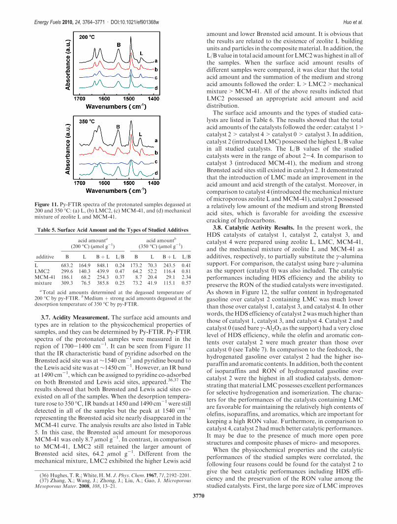
3.7. Acidity Measurement. The surface acid amounts andtypes are in relation to the physicochemical properties ofsamples, and they can be determined by Py-FTIR. Py-FTIRspectra of the protonated samples were measured in theregion of 1700-1400 cm-1. It can be seen from Figure 11that the IR characteristic band of pyridine adsorbed on theBrønsted acid site was at∼1540 cm-1 and pyridine bound tothe Lewis acid site was at∼1450 cm-1. However, an IR bandat 1490 cm-1, which can be assigned to pyridine co-adsorbedon both Brønsted and Lewis acid sites, appeared.36,37 Theresults showed that both Brønsted and Lewis acid sites co-existed on all of the samples. When the desorption tempera-ture rose to 350 �C, IRbands at 1450 and 1490 cm-1 were stilldetected in all of the samples but the peak at 1540 cm-1
representing the Brønsted acid site nearly disappeared in theMCM-41 curve. The analysis results are also listed in Table5. In this case, the Brønsted acid amount for mesoporousMCM-41 was only 8.7 μmol g-1. In contrast, in comparisonto MCM-41, LMC2 still retained the larger amount ofBrønsted acid sites, 64.2 μmol g-1. Different from themechanical mixture, LMC2 exhibited the higher Lewis acid
amount and lower Brønsted acid amount. It is obvious thatthe results are related to the existence of zeolite L buildingunits and particles in the compositematerial. In addition, theL/B value in total acid amount forLMC2was highest in all ofthe samples. When the surface acid amount results ofdifferent samples were compared, it was clear that the totalacid amount and the summation of the medium and strongacid amounts followed the order: L>LMC2>mechanicalmixture>MCM-41. All of the above results indicted thatLMC2 possessed an appropriate acid amount and aciddistribution.
The surface acid amounts and the types of studied cata-lysts are listed in Table 6. The results showed that the totalacid amounts of the catalysts followed the order: catalyst 1>catalyst 2> catalyst 4> catalyst 0> catalyst 3. In addition,catalyst 2 (introduced LMC) possessed the highest L/B valuein all studied catalysts. The L/B values of the studiedcatalysts were in the range of about 2-4. In comparison tocatalyst 3 (introduced MCM-41), the medium and strongBrønsted acid sites still existed in catalyst 2. It demonstratedthat the introduction of LMC made an improvement in theacid amount and acid strength of the catalyst. Moreover, incomparison to catalyst 4 (introduced themechanical mixtureof microporous zeolite L andMCM-41), catalyst 2 possesseda relatively low amount of the medium and strong Brønstedacid sites, which is favorable for avoiding the excessivecracking of hydrocarbons.
3.8. Catalytic Activity Results. In the present work, theHDS catalysts of catalyst 1, catalyst 2, catalyst 3, andcatalyst 4 were prepared using zeolite L, LMC, MCM-41,and the mechanical mixture of zeolite L and MCM-41 asadditives, respectively, to partially substitute the γ-aluminasupport. For comparison, the catalyst using bare γ-aluminaas the support (catalyst 0) was also included. The catalyticperformances including HDS efficiency and the ability topreserve the RON of the studied catalysts were investigated.As shown in Figure 12, the sulfur content in hydrogenatedgasoline over catalyst 2 containing LMC was much lowerthan those over catalyst 1, catalyst 3, and catalyst 4. In otherwords, theHDS efficiency of catalyst 2wasmuchhigher thanthose of catalyst 1, catalyst 3, and catalyst 4. Catalyst 2 andcatalyst 0 (used bare γ-Al2O3 as the support) had a very closelevel of HDS efficiency, while the olefin and aromatic con-tents over catalyst 2 were much greater than those overcatalyst 0 (see Table 7). In comparison to the feedstock, thehydrogenated gasoline over catalyst 2 had the higher iso-paraffin and aromatic contents. In addition, both the contentof isoparaffins and RON of hydrogenated gasoline overcatalyst 2 were the highest in all studied catalysts, demon-strating thatmaterial LMCpossesses excellent performancesfor selective hydrogenation and isomerization. The charac-ters for the performances of the catalysts containing LMCare favorable for maintaining the relatively high contents ofolefins, isoparaffins, and aromatics, which are important forkeeping a high RON value. Furthermore, in comparison tocatalyst 4, catalyst 2 hadmuch better catalytic performances.It may be due to the presence of much more open porestructures and composite phases of micro- and mesopores.
When the physicochemical properties and the catalyticperformances of the studied samples were correlated, thefollowing four reasons could be found for the catalyst 2 togive the best catalytic performances including HDS effi-ciency and the preservation of the RON value among thestudied catalysts. First, the large pore size of LMC improves
Figure 11. Py-FTIR spectra of the protonated samples degassed at200 and 350 �C: (a) L, (b) LMC2, (c) MCM-41, and (d) mechanicalmixture of zeolite L and MCM-41.
Table 5. Surface Acid Amount and the Types of Studied Additives
acid amounta
(200 �C) (μmol g-1)acid amountb
(350 �C) (μmol g-1)
additive B L B þ L L/B B L B þ L L/B
L 683.2 164.9 848.1 0.24 173.2 70.3 243.5 0.41LMC2 299.6 140.3 439.9 0.47 64.2 52.2 116.4 0.81MCM-41 186.1 68.2 254.3 0.37 8.7 20.4 29.1 2.34mixture 309.3 76.5 385.8 0.25 73.2 41.9 115.1 0.57
aTotal acid amounts determined at the degassed temperature of200 �C by py-FTIR. bMedium þ strong acid amounts degassed at thedesorption temperature of 350 �C by py-FTIR.
(36) Hughes, T. R.;White, H.M. J. Phys. Chem. 1967, 71, 2192–2201.(37) Zhang, X.; Wang, J.; Zhong, J.; Liu, A.; Gao, J. Microporous
Mesoporous Mater. 2008, 108, 13–21.

3771
Energy Fuels 2010, 24, 3764–3771 : DOI:10.1021/ef901368w Huo et al.
the diffusion ability of large molecules of reactants andproducts. Second, the relatively large amount of acid sitesenhances the cracking of the C-S bond, thus improving theHDS efficiency.38-40 Third, a relatively large amount of
weak Brønsted acid sites is helpful for the isomerizationreaction. Fourth, the appropriate ratio of the L/B value(in the present work, the appropriate L/B value is in therange of 2-4) favors the aromatization reaction.41 Espe-cially, the aromatization reaction of hydrocarbons can pro-vide obvious contributions to enhance the RON value ofhydrogenated gasoline.
4. Conclusions
(1) A kind of micro- and mesoporous composite molecularsieve was synthesized by the self-assembly of zeolite L nano-crystal clusters in the presence of template CTAB. The resultsdemonstrated that these materials possessed the compositepore structures with micro- and mesopores, appropriate acidproperties, and excellent hydrothermal stability. (2) In com-parison to the catalysts containing conventional microporouszeolite L ormesoporousMCM-41 or used bare alumina as thesupport, the catalyst introducing the micro- and mesoporouscomposites showed excellent multifunctional performances inthe HDS reaction of full-range FCC gasoline. The multi-functional performances included desulfurization, isomeriza-tion, aromatization, andpreservingolefin and theRONvalue.The excellent catalytic performances of the catalysts should beattributed to appropriate acidity distribution and the openpore structure of the compositematerial. As a result, the supercharacters and the multifunctional performances of selectivehydrogenation, isomerization, and aromatization over thecatalysts that introduced such micro- and mesoporous mate-rials should play an important role in preserving the RONvalue of hydrogenated gasoline.
Acknowledgment. This work was supported by the NationalNatural Science Foundation of China (20833011, 20773163, and20876174) and the Ministry of Science and Technology of Petro-China Company Limited (2008A-3801).
Table 6. Surface Acid Amount, Acid Types, and Specific Surface Area of the Catalysts That Introduced Different Additives
acid amount (200 �C) (μmol g-1) acid amount (350 �C) (μmol g-1)
catalyst B L B þ L L/B B L B þ L L/B
catalyst 0 0 243.1 243.1 B/L=0 0 92.5 92.5 B/L=0catalyst 1 121.3 257.2 378.5 2.1 39.3 84.9 124.2 2.2catalyst 2 73.2 248.2 321.4 3.4 16.2 59.6 75.8 3.7catalyst 3 51.3 136.6 187.9 2.7 0 42.9 42.9 B/L=0catalyst 4 90.2 167.2 257.4 1.9 23.4 57.3 80.7 2.4
Figure 12. Comparison charts of the sulfur content and RON ofgasoline obtained over different HDS catalysts. The evaluationconditions of the hydrogenation reaction are 270 �C, 2.0 MPa,2.0 h-1 (WHSV), and 300 (H2/oil), respectively. (/)W(S) is the sulfurcontent of hydrogenated gasoline.
Table 7. GroupCompositions ofGasolineObtained byCatalysts That
Introduced Different Additives
group compositions of gasoline (wt %)
sample n-paraffin i-paraffin olefin naphthene aromatics
feed 4.61 32.39 33.90 8.16 20.94catalyst 0 18.27 42.10 5.15 12.19 22.29catalyst 1 11.98 43.79 8.02 12.70 23.51catalyst 2 8.43 45.28 12.15 11.23 22.91catalyst 3 12.39 42.28 10.02 12.06 23.25catalyst 4 11.79 43.21 9.54 12.43 23.03
(38) Breysse, M.; Cattenot, M.; Kougionas, V.; Lavalley, J. C.;Mauge, F.; Portefaix, J. L.; Zotin, J. J. Catal. 1997, 168, 143–153.(39) H�edoire, C. E.; Louis, C.; Davidson, A.; Breysse,M.;Maug�e, F.;
Vrinat, M. J. Catal. 2003, 220, 433–441.(40) Gutierrez, O. Y.; Fuentes, G. A.; Salcedo, C.; Klimova, T.Catal.
Today 2006, 16, 485–497.(41) Wang, P.; Shen, B. J.; Gao, J. S. Catal. Commun. 2007, 8, 1161–
1166.
Copyright © 2022 FDOKUMEN