Singularity avoidance for over-actuated, pseudo-omnidirectional, wheeled mobile robots
Contents lists available at ScienceDirect
Mechanical Systems and Signal Processing
Mechanical Systems and Signal Processing 60-61 (2015) 770–784
http://d0888-32
n CorrE-m
journal homepage: www.elsevier.com/locate/ymssp
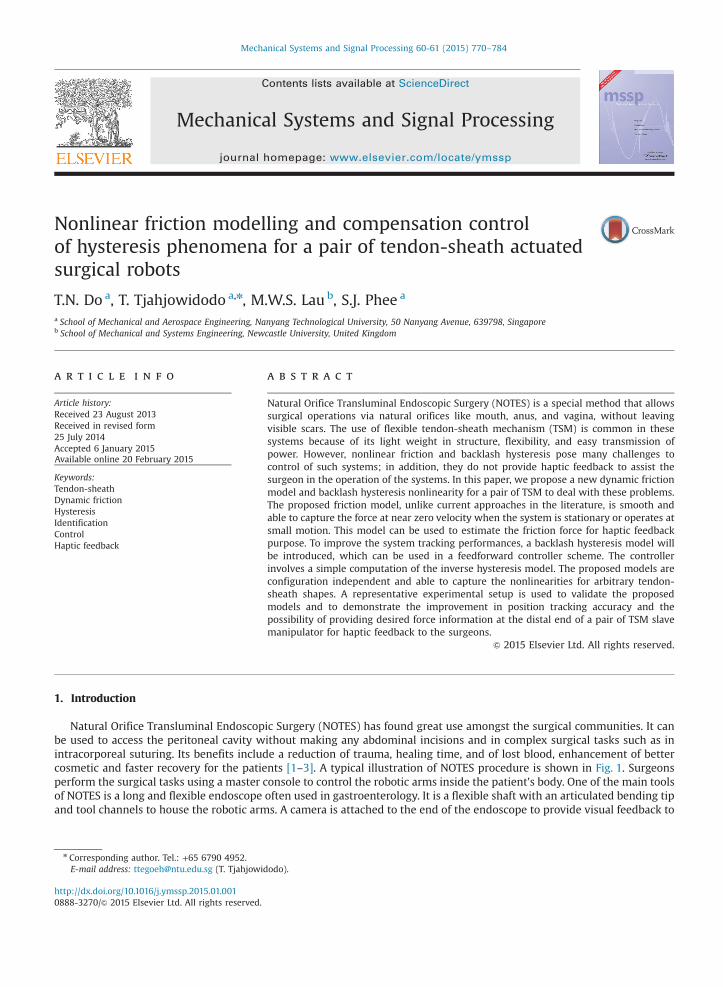
Nonlinear friction modelling and compensation controlof hysteresis phenomena for a pair of tendon-sheath actuatedsurgical robots
T.N. Do a, T. Tjahjowidodo a,n, M.W.S. Lau b, S.J. Phee a
a School of Mechanical and Aerospace Engineering, Nanyang Technological University, 50 Nanyang Avenue, 639798, Singaporeb School of Mechanical and Systems Engineering, Newcastle University, United Kingdom
a r t i c l e i n f o
Article history:Received 23 August 2013Received in revised form25 July 2014Accepted 6 January 2015Available online 20 February 2015
Keywords:Tendon-sheathDynamic frictionHysteresisIdentificationControlHaptic feedback
x.doi.org/10.1016/j.ymssp.2015.01.00170/& 2015 Elsevier Ltd. All rights reserved.
esponding author. Tel.: +65 6790 4952.ail address: [email protected] (T. Tjahjowid
a b s t r a c t
Natural Orifice Transluminal Endoscopic Surgery (NOTES) is a special method that allowssurgical operations via natural orifices like mouth, anus, and vagina, without leavingvisible scars. The use of flexible tendon-sheath mechanism (TSM) is common in thesesystems because of its light weight in structure, flexibility, and easy transmission ofpower. However, nonlinear friction and backlash hysteresis pose many challenges tocontrol of such systems; in addition, they do not provide haptic feedback to assist thesurgeon in the operation of the systems. In this paper, we propose a new dynamic frictionmodel and backlash hysteresis nonlinearity for a pair of TSM to deal with these problems.The proposed friction model, unlike current approaches in the literature, is smooth andable to capture the force at near zero velocity when the system is stationary or operates atsmall motion. This model can be used to estimate the friction force for haptic feedbackpurpose. To improve the system tracking performances, a backlash hysteresis model willbe introduced, which can be used in a feedforward controller scheme. The controllerinvolves a simple computation of the inverse hysteresis model. The proposed models areconfiguration independent and able to capture the nonlinearities for arbitrary tendon-sheath shapes. A representative experimental setup is used to validate the proposedmodels and to demonstrate the improvement in position tracking accuracy and thepossibility of providing desired force information at the distal end of a pair of TSM slavemanipulator for haptic feedback to the surgeons.
& 2015 Elsevier Ltd. All rights reserved.
1. Introduction
Natural Orifice Transluminal Endoscopic Surgery (NOTES) has found great use amongst the surgical communities. It canbe used to access the peritoneal cavity without making any abdominal incisions and in complex surgical tasks such as inintracorporeal suturing. Its benefits include a reduction of trauma, healing time, and of lost blood, enhancement of bettercosmetic and faster recovery for the patients [1–3]. A typical illustration of NOTES procedure is shown in Fig. 1. Surgeonsperform the surgical tasks using a master console to control the robotic arms inside the patient's body. One of the main toolsof NOTES is a long and flexible endoscope often used in gastroenterology. It is a flexible shaft with an articulated bending tipand tool channels to house the robotic arms. A camera is attached to the end of the endoscope to provide visual feedback to
odo).
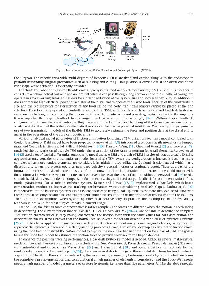
Fig. 1. Illustration of a Natural Orifice Transluminal Endoscopic System (NOTES).
T.N. Do et al. / Mechanical Systems and Signal Processing 60-61 (2015) 770–784 771
the surgeon. The robotic arms with multi degrees of freedom (DOFs) are fixed and carried along with the endoscope toperform demanding surgical procedures such as suturing and cutting. Triangulation is carried out at the distal end of theendoscope while actuation is externally provided.
To actuate the robotic arms in the flexible endoscopic systems, tendon-sheath mechanism (TSM) is used. This mechanismconsists of a hollow helical coil wire and an internal cable; it can pass through long narrow and tortuous paths allowing it tooperate in small working areas. This allows for a drastic reduction of the system size and increases flexibility. In addition, itdoes not require high electrical power or actuator at the distal end to operate the slaved tools. Because of the constraints insize and the requirements for sterilization of any tools inside the body, traditional sensors cannot be placed at the endeffectors. Therefore, only open-loop controllers are used. In TSM, nonlinearities such as friction and backlash hysteresiscause major challenges in controlling the precise motion of the robotic arms and providing haptic feedback to the surgeons.It was reported that haptic feedback to the surgeon will be essential for safe surgery [4–6]. Without haptic feedback,surgeons cannot have the same feeling as they have with direct contact and handling of the tissues. As sensors are notavailable at distal end of the system, mathematical models can be used as potential substitutes. We develop and propose theuse of two transmission models of the flexible TSM to accurately estimate the force and position data at the distal end toassist in the operations of the surgical robotic arms.
Various analytical model parameters of friction and motion for a single TSM using lumped mass model combined withCoulomb friction or Dahl model have been proposed. Kaneko et al. [7,8] introduced a tendon-sheath model using lumpedmass and Coulomb friction model. Palli and Melchiorri [9,10], Tian and Wang [11], Chen and Wang.[12] and Low et.al [13]modelled the transmission of a single TSM under the assumption of the same pretension for small elements. Agrawal et al.[14,15] used a set of partial differential equations to model a single TSM and a pair of TSM in a closed loop approach. Existingapproaches only consider the transmission model for a single TSM when the configuration is known. It becomes morecomplex when more tendon elements are considered. In addition, they utilize the Coulomb friction model which has adiscontinuity when the system operates near zero velocity (reversal motion or stationary state). These approaches areimpractical because the sheath curvatures are often unknown during the operation and because they could not provideforce information when the system operates near zero velocity i.e. at the onset of motion. Although Agrawal et al.[16] used asmooth backlash inverse model to compensate for the errors, they still need output feedback for online estimation of themodel parameters. For a robotic catheter system, Kesner and Howe [17,18] implemented a backlash width-basedcompensation method to improve the tracking performances without considering backlash slopes. Bardou et al. [19]compensated for the backlash hysteresis in a flexible endoscope using a look-up table to estimate the dead-band. However,these approaches only consider the control problems under the assumption of the presence of feedbacks from the tool tips.There are still discontinuities when system operates near zero velocity. In practice, this assumption of the availabilityfeedback is not valid for most surgical robots in current usage.
For the TSM, the friction force characteristics is rather complex. The forces are different when the motion is acceleratingor decelerating. The current friction models like Dahl, LuGre, Leuven, or GMS [20–24] are not able to describe the completeTSM friction characteristics as they mainly characterize the friction force with the same values for both acceleration anddeceleration phases. It was known that the normalized Bouc–Wen model can describe a wide class of hysteresis systems[25,26]. It has been applied in many systems, such as in structure element analysis and magnetorheological systems, torepresent the hysteresis inherence in such engineering problems. Hence, here we will develop an asymmetric friction modelusing the modified normalized Bouc–Wen model to capture the nonlinear behavior of friction for a pair of TSM. The goal isto use this modified model to estimate the friction force to provide feedback to the haptic devices.
To enhance the position tracking performances, a backlash hysteresis model is needed. Although several mathematicalmodels of backlash hysteresis nonlinearities including the Bouc–Wen model, Preisach model, Prandtl-Ishlinskii (PI) modelwere introduced and discussed in Macki et al. [27] and Hassani et al. [28], and some identification methods for thenonlinearity are widely discussed (e.g. [29,30]), there are several shortcomings in these model structures for tendon-sheathapplications. The PI and Preisach are modelled by the sum of many elementary hysteresis namely hysterons, which increasesthe complexity in implementation and computation if a high number of elements is considered; and the Bouc–Wen modelneeds a high number of model parameters to capture hysteresis, i.e. more than five parameters. Unlike the above models,
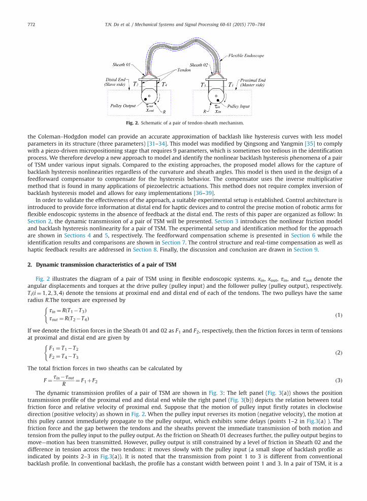
Fig. 2. Schematic of a pair of tendon-sheath mechanism.
T.N. Do et al. / Mechanical Systems and Signal Processing 60-61 (2015) 770–784772
the Coleman–Hodgdon model can provide an accurate approximation of backlash like hysteresis curves with less modelparameters in its structure (three parameters) [31–34]. This model was modified by Qingsong and Yangmin [35] to complywith a piezo-driven micropositioning stage that requires 9 parameters, which is sometimes too tedious in the identificationprocess. We therefore develop a new approach to model and identify the nonlinear backlash hysteresis phenomena of a pairof TSM under various input signals. Compared to the existing approaches, the proposed model allows for the capture ofbacklash hysteresis nonlinearities regardless of the curvature and sheath angles. This model is then used in the design of afeedforward compensator to compensate for the hysteresis behavior. The compensator uses the inverse multiplicativemethod that is found in many applications of piezoelectric actuations. This method does not require complex inversion ofbacklash hysteresis model and allows for easy implementations [36–39].
In order to validate the effectiveness of the approach, a suitable experimental setup is established. Control architecture isintroduced to provide force information at distal end for haptic devices and to control the precise motion of robotic arms forflexible endoscopic systems in the absence of feedback at the distal end. The rests of this paper are organized as follow: InSection 2, the dynamic transmission of a pair of TSM will be presented. Section 3 introduces the nonlinear friction modeland backlash hysteresis nonlinearity for a pair of TSM. The experimental setup and identification method for the approachare shown in Sections 4 and 5, respectively. The feedforward compensation scheme is presented in Section 6 while theidentification results and comparisons are shown in Section 7. The control structure and real-time compensation as well ashaptic feedback results are addressed in Section 8. Finally, the discussion and conclusion are drawn in Section 9.
2. Dynamic transmission characteristics of a pair of TSM
Fig. 2 illustrates the diagram of a pair of TSM using in flexible endoscopic systems. xin, xout, τin, and τout denote theangular displacements and torques at the drive pulley (pulley input) and the follower pulley (pulley output), respectively.Tiði¼ 1;2;3;4Þ denote the tensions at proximal end and distal end of each of the tendons. The two pulleys have the sameradius R.The torques are expressed by
τin ¼ RðT1�T3Þτout ¼ RðT2�T4Þ
(ð1Þ
If we denote the friction forces in the Sheath 01 and 02 as F1 and F2, respectively, then the friction forces in term of tensionsat proximal and distal end are given by
F1 ¼ T1�T2
F2 ¼ T4�T3
(ð2Þ
The total friction forces in two sheaths can be calculated by
F ¼ τin�τoutR
¼ F1þF2 ð3Þ
The dynamic transmission profiles of a pair of TSM are shown in Fig. 3: The left panel (Fig. 3(a)) shows the positiontransmission profile of the proximal end and distal end while the right panel (Fig. 3(b)) depicts the relation between totalfriction force and relative velocity of proximal end. Suppose that the motion of pulley input firstly rotates in clockwisedirection (positive velocity) as shown in Fig. 2. When the pulley input reverses its motion (negative velocity), the motion atthis pulley cannot immediately propagate to the pulley output, which exhibits some delays (points 1–2 in Fig.3(a) ). Thefriction force and the gap between the tendons and the sheaths prevent the immediate transmission of both motion andtension from the pulley input to the pulley output. As the friction on Sheath 01 decreases further, the pulley output begins tomove—motion has been transmitted. However, pulley output is still constrained by a level of friction in Sheath 02 and thedifference in tension across the two tendons: it moves slowly with the pulley input (a small slope of backlash profile asindicated by points 2–3 in Fig.3(a)). It is noted that the transmission from point 1 to 3 is different from conventionalbacklash profile. In conventional backlash, the profile has a constant width between point 1 and 3. In a pair of TSM, it is a
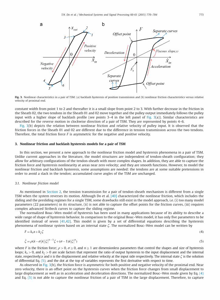
Fig. 3. Nonlinear characteristics in a pair of TSM: (a) backlash hysteresis of position transmission and (b) nonlinear friction characteristics versus relativevelocity of proximal end.
T.N. Do et al. / Mechanical Systems and Signal Processing 60-61 (2015) 770–784 773
constant width from point 1 to 2 and thereafter it is a small slope from point 2 to 3. With further decrease in the friction inthe Sheath 02, the two tendons in the Sheath 01 and 02 move together and the pulley output immediately follows the pulleyinput with a higher slope of backlash profile (see points 3–4 in the left panel of Fig. 3(a)). Similar characteristics aredescribed for the reverse motion in clockwise direction of a pair of TSM. They are represented by points 4–6.
Fig. 3(b) depicts the relation between nonlinear friction and relative velocity of pulley input. It is observed that thefriction forces in the Sheath 01 and 02 are different due to the difference in tension transmission across the two tendons.Therefore, the total friction force F is asymmetric for the negative and positive velocity.
3. Nonlinear friction and backlash hysteresis models for a pair of TSM
In this section, we present a new approach to the nonlinear friction model and hysteresis phenomena in a pair of TSM.Unlike current approaches in the literature, the model structures are independent of tendon-sheath configuration; theyallow for arbitrary configurations of the tendon-sheath with more complex shapes. In addition, they are able to capture thefriction force and hysteresis nonlinearity at areas near zero velocity; and they are smooth functions. However, to model thenonlinear friction and backlash hysteresis, some assumptions are needed: the tendons are at some suitable pretensions inorder to avoid a slack in the tendon; accumulated curve angles of the TSM are unchanged.
3.1. Nonlinear friction model
As mentioned in Section 2, the tension transmission for a pair of tendon-sheath mechanism is different from a singleTSM when the system reverses its motion. Although Do et al. [40] characterized the nonlinear friction, which includes thesliding and the presliding regimes for a single TSM, some drawbacks still exist in the model approach, i.e. (i) too many modelparameters (22 parameters) in its structure, (ii) is not able to capture the offset points for the friction curves, (iii) requirescomplex advanced Stribeck curves to capture the sliding regime.
The normalized Bouc–Wen model of hysteresis has been used in many applications because of its ability to describe awide range of shape of hysteresis behavior. In comparison to the original Bouc–Wen model, it has only five parameters to beidentified instead of seven [41,42]. This model is given by a set of differential equations describing the hysteresisphenomena of nonlinear system based on an internal state ζ. The normalized Bouc–Wen model can be written by
F ¼ kxxþkζζ ð4Þ
_ζ ¼ ρð_x�σ _x�� �� ζ�� ��n�1ζþðσ�1Þ_x ζ
�� ��nÞ ð5Þ
where F is the friction force; ρ40, σZ0, and nZ1 are dimensionless parameters that control the shapes and size of hysteresisloops; kx40, and kζ40 are scale factors that represent the ratio of output hysteresis to the input displacement and the internalstate, respectively;x and _x is the displacement and relative velocity at the input side respectively. The internal state ζ is the solutionof differential Eq. (5); and the dot at the top of variables represents the first derivative with respect to time.
As observed in Fig. 3(b), the friction force is asymmetric for both positive and negative velocity of the proximal end. Nearzero velocity, there is an offset point on the hysteresis curves when the friction force changes from small displacement tolarge displacement as well as in acceleration and deceleration directions. The normalized Bouc–Wen mode given by Eq. (4)and Eq. (5) is not able to capture the nonlinear friction of a pair of TSM in the large displacement. Therefore, to capture
T.N. Do et al. / Mechanical Systems and Signal Processing 60-61 (2015) 770–784774
asymmetric characteristics, our approach is to modify the normalized Bouc–Wen model. Two major modifications areintroduced. The first is the modification of the velocity variable in Eq. (5) to be a function of the offset point and theacceleration of proximal end. Therefore, the Eq. (5) is replaced by
_ζ ¼ ρð_xþλsignð€xÞ�σ _xþλsignð€xÞ�� �� ζ�� ��n�1ζþðσ�1Þð_xþλsignð€xÞÞ ζ
�� ��nÞ ð6Þ
where λ is the offset point of the adjustment; signð�Þ is the signum function that is defined by
signð�Þ ¼1ifð�Þ400ifð�Þ ¼ 0�1 ifð�Þo0
8><>: .
The second is the modification of the scale factor for x in (4), which represents the separate curves (Fig. 3(b)) in theacceleration and deceleration direction, to include smooth functions of stiffness, velocity, and acceleration. The modifiedterm kxð_x; €xÞ, which controls the hysteresis asymmetric loops with large displacement for negative and positive velocity, isexpressed as
kxð_x; €xÞ ¼ 0:5kx 1þ tanhð_xÞþ 1� tanhð_xÞð ÞsignðxÞsignð€xÞð Þ ¼ 0:5kx2e2_x
e2_xþ1þ 2
e2_xþ1
� �signðxÞsignð€xÞ
� �
¼ kxe2_xþ1
e2_xþsignðxÞsignð€xÞ� �
where the hyperbolic tangent is defined as tanhð_xÞ ¼ e2_x �1e2_x þ1;
To capture the slope of the hysteresis loops for positive and negative velocity, a viscous friction term is added to theEq. (4). The friction force with asymmetric hysteresis loops of different stiffness kxð_x; €xÞ is then given by
F ¼ kxð_x; €xÞxþkζζþυ_xþF0
kxð_x; €xÞ ¼ kxe2_x þ1 e2_xþsignðxÞsignð€xÞ� �
8<: ð7Þ
F0 is an offset of friction force; kx is now the stiffness factor that controls the separate curves of the hysteresis loops; υ isviscous coefficient that represents the incline line of the friction force in relation with the velocity. A large value of υ meansthat the hysteresis loops has a steep inclination.
The new model given by Eq. (6) and Eq. (7) describes the nonlinear friction in a pair of TSM without using anyinformation of the tendon-sheath configurations in its model structure with 8 (eight) parameters, i.e. ρ, λ, σ, n, kx, kζ, υ andF0. In addition, at the vicinity of zero velocity, the proposed model is able to capture the friction force in comparison withcurrent approaches in the literature where they are utilizing the Coulomb model with discontinuity near zero velocity.Experimental demonstrations will be carried out in Section 6.
3.2. Modelling of backlash hysteresis nonlinearities
The backlash hysteresis nonlinearity of position in the TSM is due to nonlinear friction and the tendon-sheathconfiguration. It is very important to model these hysteresis phenomena for the tendon position in order to obtain preciseposition control at the distal end. It is observed that the nonlinearities of tendon-sheath displacement follow a class ofbacklash-like hysteresis as presented in Fig. 3(a). For positive velocity, the output increases linearly with the input. Whenthe input changes its direction, the output does not immediately change together with the input. In the transition phase, theoutput keeps its previous value at the transition point (a dead band) before slightly reducing together with the input. In aconventional backlash as presented by Tao and Kokotovic [43–45], the transition phase is a backlash nonlinearity with afixed width for the dead band for the whole phase. However, in the case of a pair of TSM, the transition phase is acombination of dead band and an inclined line. Su et al. [33] and Ahmad et al. [34] indicated that the backlash hysteresismodel presented by Tao et al. [43–45] is discontinuous itself and may be not suitable for the system control. In this paper, todescribe such a backlash hysteresis phenomenon in a pair of TSM, a continuous backlash-like hysteresis model namely theColeman–Hodgdon model will be used [31–35]. This model approximates conventional backlash hysteresis nonlinearity; asdescribed by
_xout ¼ α _xin�� ��ðcxin�xoutÞþB_xin; xoutð0Þ ¼ xout_0 ð8Þ
where xin is the input,xout is the output, xout_0 is initial value of the output at time t ¼ 0. The parameter must satisfy theconditions α40, B40, and c4B. The dot at the top of the variables represents the first derivative with respect to time.
The relation between the input and output of the Coleman–Hodgdon model has a property that they are monotonicallyincreasing and decreasing between the two extrema. The backlash-like hysteresis model (8) can be solved explicitly in adifferent form of identical input–output response. The output xout of a pair of TSM as in Fig. 2can be found with the followingproposition:
T.N. Do et al. / Mechanical Systems and Signal Processing 60-61 (2015) 770–784 775
Proposition 1. Let xin, the displacement at proximal end, and its first derivative _xin, be continuous in time and be bounded. Forall possibilities of the sign of _xin, the displacement at distal end xout satisfies Eq. (8). The initial conditions of the two displacementssatisfy xoutðxin_0Þ ¼ xout_0 where xin_0 and xout_0 are initial values of proximal and distal displacement at the two ends at time t ¼ 0,respectively. Then the solution of the backlash hysteresis model of (8) can be expressed in a new form of a line possessing slope cand a switching function given by .
xout ¼ cxinþxh ð9Þ
_xh ¼ β _xin�α _xin�� ��xh ð10Þ
where α40, c40, and β¼ ðB�cÞo0
Proof. For all possibilities of the sign of _xin, Eq. (8) can be rewritten as:
_xout ¼ ðαðcxin�xoutÞþBÞ_xin if _xinZ0 ð11Þand
_xout ¼ ð�αðcxin�xoutÞþBÞ_xin if _xino0 ð12ÞFor the case of _xinZ0, we will find the solution of Eq. (11) by the following relation:
dxoutdxin
¼ αðcxin�xoutÞþB 3dxoutdxin
þαxout ¼ αcxinþB ð13Þ
The solution of (13) can be expressed as
xout ¼ e�Rαdxin
ZeRαdxin ðαcxinþBÞdxinþCþ
� �
¼ e�αxinZ
eαxin ðαcxinþBÞdxinþCþ
� �¼ e�αxin
ZαcxineαxindxinþB
ZeαxindxinþCþ
� �ð14Þ
We haveRαcxineαxindxin ¼ c xin� 1
α
� �eαxin and B
Reαxindxin ¼ B
αeαxin , then (14) is rewritten as
xout ¼ cxinþB� cα þCþ e�αxin
At time t ¼ 0; xout_0 ¼ cxin_0þB�cα
þCþ e�αxin_0
) Cþ ¼ xout_0�cxin_0�B�cα
� �eαxin_0 ð15Þ
Similarly, for the case of _xino0, we find the solution of (12) by writing
dxoutdxin
¼ �αðcxin�xoutÞþB 3dxoutdxin
�αxout ¼ �αcxinþB ð16Þ
) xout ¼ cxin�B�cα
þC� eαxin ð17Þ
where at time t ¼ 0, xoutðxin_0Þ ¼ xout_0 ) C� ¼ xout_0�cxin_0þB� cα
� �e�αxin_0
From (15) and (17), the solution of (8) can be rewritten in term of
xout ¼ cxinþxh
where xh is the solution of a differential equation
_xh ¼ ðB�cÞ_xin�α _xin�� ��xh ð18Þ
actually, the solution of (18) can be explicitly solved using the form in (14) for the two possibilities of _xin.For the case of _xinZ0, (18) can be expressed by dxh
dxinþαxh ¼ B�c
) xh ¼ e�Rαdxin
ZeRαdxin ðB�cÞdxinþDþ
� �¼ B�c
αþDþ e�αxin ð19Þ
For the case of_xino0, (18) can be expressed by dxhdxin
�αxh ¼ B�c
) xh ¼ eRαdxin
Ze�
Rαdxin ðB�cÞdxinþD�
� �¼ �B�c
αþD� eαxin ð20Þ
it is easy to see that the second terms in the right side of (15) and (17) are the same as (19) and (20).
Please note that the results of (9) and (10) represent a straight line of slope c and a smooth hysteresis function xh. Thepurpose of expressions (8)–(10) is to allow for the design of a new controller with (9) without using complex inversion inthe feedforward compensation of the backlash hysteresis in the system. It will be introduced in Section 6.
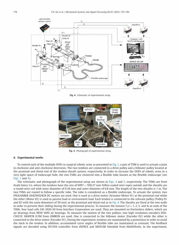
Fig. 4. Schematic of experimental setup.
Fig. 5. Photograph of experimental setup.
T.N. Do et al. / Mechanical Systems and Signal Processing 60-61 (2015) 770–784776
4. Experimental works
To control each of the multiple DOFs in surgical robotic arms as presented in Fig. 1, a pair of TSM is used to actuate a jointin clockwise and anti-clockwise directions. The two tendons are connected to a drive pulley and a follower pulley located atthe proximal and distal end of the tendon-sheath system, respectively. In order to increase the DOFs of robotic arms in avery tight space of endoscope hole, the two TSMs are clustered into a flexible tube known as the flexible endoscope (seeFigs. 1 and 4).
The schematic and photograph of the experimental setup are shown in Figs. 4 and 5, respectively. The TSMs are fromAsahi Intecc Co. where the tendons have the size of WR7�7D0.27 mm Teflon coated wire ropes outside and the sheaths area round-wire coil with inner diameter of 0.36 mm and outer diameter of 0.8 mm. The length of the two sheaths is 1 m. Thetwo TSMs are routed to follow a specific tube. The tube is considered as a flexible endoscope. To actuate the system, twoFAULHABER 2642W024CR DC motors are used. One is used as a drive motor (Actuator-Motor 01) at the proximal end whilethe other (Motor 02) is used as passive load or environment load. Each tendon is connected to the relevant pulley (Pulley 01and 02 with the same diameters of 50 mm) at the proximal and distal end as in Fig. 4. The sheaths are fixed at the two wallsin order to prevent their sliding during the experimental process. To measure the tension Tiði¼ 1;2;3; and 4Þ at ends of theTSMs, four load cells LW-1020-50 from Interface Corporation are used. They are mounted on frictionless sliders, which areair bearings from NEW WAY air bearings. To measure the motion of the two pulleys, two high resolution encoders E6D-CWZ1E 3600P/R 0.5M from OMRON are used. One is connected to the follower motor (Encoder 02) while the other isconnected to the drive motor (Encoder 01). During the experiment, tendons are maintained by a pretension in order to avoidthe slack in the tendon. In addition, accumulated curve angles of flexible tube are maintained as constant. The feedbacksignals are decoded using DS1104 controller from dSPACE and MATLAB Simulink from MathWorks. In the experiment,
T.N. Do et al. / Mechanical Systems and Signal Processing 60-61 (2015) 770–784 777
various excitations are provided to the drive motor (Motor 01) to investigate the position and nonlinear friction profiles of apair of TSMs.
5. Model identification with genetic algorithm (GA)
The identification of the 10 model parameters, which consist of seven parameters of the friction force and threeparameters of the backlash hysteresis, are carried out offline. Parameters of the models are firstly identified using GeneticAlgorithm (GA). GA is a global searching method based on the natural selection and genetics including operators ofcrossover, mutation, reproduction [46,47]. The GA will generate an initial guess of model parameters. Subsequently, theobtained model parameters will be used as an initial guess in the Nelder–Mead Simplex method to refine the result. Duringthe identification process, MATLAB identification Toolbox from MathWorks is used. To evaluate the performance of theidentification, the mean square error (MSE) is used and defined by
MSE¼ 1N
XNi ¼ 1
f actualðiÞ� f modelðiÞ� �2 ð21Þ
subject to suitable equality constraints and inequality constraints.where i is sampling index and N is total number of samples from experimental results, f actual is actual experimental data
of the tendon-sheath system (displacement or friction force), f model is the estimated values obtained from the proposedfriction and backlash hysteresis models. The fitness function MSE is defined as the mean square error between the proposedmodels and actual experimental data. The experimental data in the identification process are filtered using zero-phasedigital filtering with filtfilt command in MATLAB. Having all the model parameters identified offline; those parameters willbe used in the experiments under the same condition (e.g. same equipment and same pretension for the tendon).
6. Feedforward tracking control
Because of the need for sterilization and constraint in size, sensors cannot be used at the joints of robotic arms to providenecessary feedbacks for torque and position. Therefore, only feedforward control scheme can be used to compensate thebacklash hysteresis nonlinearities. In addition, in this paper, the feedforward controller is implemented to validate theproposed backlash-hysteresis model.
Kesner and Howe [18] indicated that the compensation of friction does not reduce the backlash hysteresis effectsbetween the catheter and the sheath. Therefore, to enhance the position tracking performances of a pair of TSM, backlashhysteresis model of displacement is used, instead of the friction model, in the feedforward controller to compensate thebacklash hysteresis effects. The goal is to force the output displacement xout at the distal end to follow a desired referencetrajectory xr .
Consider reference trajectory xr; if the hysteresis term xh can be estimated by a corresponding hysteresis observer x̂h,then the hysteresis observer-based feedforward compensator can be designed. Define a new feedforward controller inputxFF at the proximal end of the system. The backlash hysteresis given by Eq. (9) can be rewritten as
xout ¼ cxFFþxh ð22Þ
If we were to choose the control input xFF as
xFF ¼1cxr� x̂h� � ð23Þ
Then xout ¼ c1cxr� x̂h� �þxh ¼ xrþ xh� x̂h
� � ð24Þ
The estimated value is defined by:
_̂xh ¼ β _xr�α _xr�� ��x̂h ð25Þ
If the value x̂h can be accurately estimated, i.e. x̂h ¼ xh, then from Eq. (24), the error between the reference trajectory xrand displacement at the distal end xout can be eliminated. It means that xout accurately tracks reference xr .
The block diagram of feedforward compensator given by Eq. (22) to Eq. (25) is illustrated in Fig. 6. A saturation function isappended in the DC-motor loop in order to constraint the controller output between the two input extremes due to thelimitation of the voltage applied to the motor (0-24VDC). It is shown that the accuracy of control scheme is based on theperformance of hysteresis observer given by Eq. (25).
The proposed friction model and compensation approaches can be implemented independently. If we do not need hapticforce feedback, we only need 3 parameters to identify for providing position tracking (this requires fewer numbers ofparameter compared to that in [35], which needs 9 parameters). The additional 7 parameters are needed for force feedbackapplications. These are fewer than the 22 parameters required by the model in our previous approach [40].
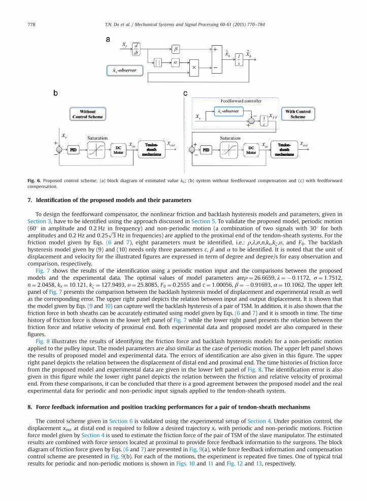
Fig. 6. Proposed control scheme; (a) block diagram of estimated value x̂h; (b) system without feedforward compensation and (c) with feedforwardcompensation.
T.N. Do et al. / Mechanical Systems and Signal Processing 60-61 (2015) 770–784778
7. Identification of the proposed models and their parameters
To design the feedforward compensator, the nonlinear friction and backlash hysteresis models and parameters, given inSection 3, have to be identified using the approach discussed in Section 5. To validate the proposed model, periodic motion(601 in amplitude and 0:2 Hz in frequency) and non-periodic motion (a combination of two signals with 301 for bothamplitudes and 0.2 Hz and 0:25
ffiffiffi3
pHz in frequencies) are applied to the proximal end of the tendon-sheath systems. For the
friction model given by Eqs. (6 and 7), eight parameters must be identified, i.e.: ρ,λ,σ,n,kx,kζ ,υ, and F0. The backlashhysteresis model given by (9) and (10) needs only three parameters c, β and α to be identified. It is noted that the unit ofdisplacement and velocity for the illustrated figures are expressed in term of degree and degree/s for easy observation andcomparison, respectively.
Fig. 7 shows the results of the identification using a periodic motion input and the comparisons between the proposedmodels and the experimental data. The optimal values of model parameters areρ¼ 26:6659, λ¼ �0:1172, σ ¼ 1:7512,n¼ 2:0458, kx ¼ 10:121, kζ ¼ 127:9493, υ¼ 25:8085, F0 ¼ 0:2555 and c¼ 1:00056, β¼ �0:91693, α¼ 10:1062. The upper leftpanel of Fig. 7 presents the comparison between the backlash hysteresis model of displacement and experimental result as wellas the corresponding error. The upper right panel depicts the relation between input and output displacement. It is shown thatthe model given by Eqs. (9 and 10) can capture well the backlash hysteresis of a pair of TSM. In addition, it is also shown that thefriction force in both sheaths can be accurately estimated using model given by Eqs. (6 and 7) and it is smooth in time. The timehistory of friction force is shown in the lower left panel of Fig. 7 while the lower right panel presents the relation between thefriction force and relative velocity of proximal end. Both experimental data and proposed model are also compared in thesefigures.
Fig. 8 illustrates the results of identifying the friction force and backlash hysteresis models for a non-periodic motionapplied to the pulley input. The model parameters are also similar as the case of periodic motion. The upper left panel showsthe results of proposed model and experimental data. The errors of identification are also given in this figure. The upperright panel depicts the relation between the displacement of distal end and proximal end. The time histories of friction forcefrom the proposed model and experimental data are given in the lower left panel of Fig. 8. The identification error is alsogiven in this figure while the lower right panel depicts the relation between the friction and relative velocity of proximalend. From these comparisons, it can be concluded that there is a good agreement between the proposed model and the realexperimental data for periodic and non-periodic input signals applied to the tendon-sheath system.
8. Force feedback information and position tracking performances for a pair of tendon-sheath mechanisms
The control scheme given in Section 6 is validated using the experimental setup of Section 4. Under position control, thedisplacement xout at distal end is required to follow a desired trajectory xr with periodic and non-periodic motions. Frictionforce model given by Section 4 is used to estimate the friction force of the pair of TSM of the slave manipulator. The estimatedresults are combined with force sensors located at proximal to provide force feedback information to the surgeons. The blockdiagram of friction force given by Eqs. (6 and 7) are presented in Fig. 9(a), while force feedback information and compensationcontrol scheme are presented in Fig. 9(b). For each of the motions, the experiment is repeated five times. One of typical trialresults for periodic and non-periodic motions is shown in Figs. 10 and 11 and Fig. 12 and 13, respectively.
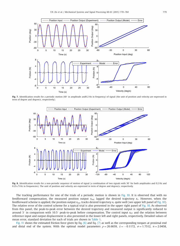
Fig. 7. Identification results for a periodic motion (601 in amplitude and0:2 Hz in frequency) of signal (the unit of position and velocity are expressed interm of degree and degree/s, respectively).
Fig. 8. Identification results for a non-periodic sequence of motion of signal (a combination of two signals with 301 for both amplitudes and 0.2 Hz and0:25
ffiffiffi3
pHz in frequencies). The unit of position and velocity are expressed in term of degree and degree/s, respectively.
T.N. Do et al. / Mechanical Systems and Signal Processing 60-61 (2015) 770–784 779
The tracking performance for one of the trials of a periodic motion is shown in Fig. 10. It is observed that with nofeedforward compensation, the measured position output xout lagged the desired trajectory xr . However, when thefeedforward scheme is applied, the position output xout tracks desired trajectory xr quite well (see upper left panel of Fig. 10).The relative error of the control scheme for a typical trial is also presented in the upper right panel of Fig. 10. As observedfrom this panel, the peak-to-peak error between the desired trajectory and measured output is significantly reduced toaround 31 in comparison with 10:51 peak-to-peak before compensation. The control input xFF and the relation betweenreference input and output displacement is also presented in the lower left and right panels, respectively. Detailed values ofmean error, standard deviation for each of trials are shown in Table 1.
Fig. 11 shows the estimated friction force given by Eq. (6) and Eq. (7) as well as the corresponding torques at proximal endand distal end of the system. With the optimal model parameters ρ¼ 26:6659, λ¼ �0:1172, σ ¼ 1:7512, n¼ 2:0458,
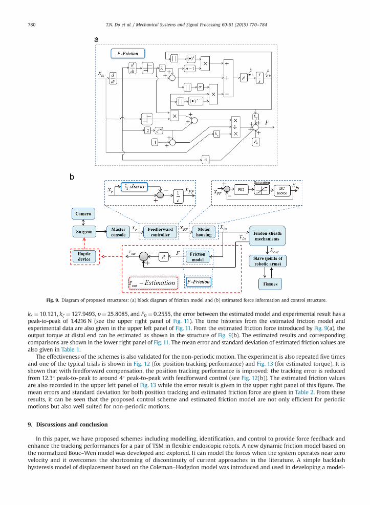
Fig. 9. Diagram of proposed structures: (a) block diagram of friction model and (b) estimated force information and control structure.
T.N. Do et al. / Mechanical Systems and Signal Processing 60-61 (2015) 770–784780
kx ¼ 10:121, kζ ¼ 127:9493, υ¼ 25:8085, and F0 ¼ 0:2555, the error between the estimated model and experimental result has apeak-to-peak of 1.4216 N (see the upper right panel of Fig. 11). The time histories from the estimated friction model andexperimental data are also given in the upper left panel of Fig. 11. From the estimated friction force introduced by Fig. 9(a), theoutput torque at distal end can be estimated as shown in the structure of Fig. 9(b). The estimated results and correspondingcomparisons are shown in the lower right panel of Fig. 11. The mean error and standard deviation of estimated friction values arealso given in Table 1.
The effectiveness of the schemes is also validated for the non-periodic motion. The experiment is also repeated five timesand one of the typical trials is shown in Fig. 12 (for position tracking performance) and Fig. 13 (for estimated torque). It isshown that with feedforward compensation, the position tracking performance is improved: the tracking error is reducedfrom 12.31 peak-to-peak to around 41 peak-to-peak with feedforward control (see Fig. 12(b)). The estimated friction valuesare also recorded in the upper left panel of Fig. 13 while the error result is given in the upper right panel of this figure. Themean errors and standard deviation for both position tracking and estimated friction force are given in Table 2. From theseresults, it can be seen that the proposed control scheme and estimated friction model are not only efficient for periodicmotions but also well suited for non-periodic motions.
9. Discussions and conclusion
In this paper, we have proposed schemes including modelling, identification, and control to provide force feedback andenhance the tracking performances for a pair of TSM in flexible endoscopic robots. A new dynamic friction model based onthe normalized Bouc–Wen model was developed and explored. It can model the forces when the system operates near zerovelocity and it overcomes the shortcoming of discontinuity of current approaches in the literature. A simple backlashhysteresis model of displacement based on the Coleman–Hodgdon model was introduced and used in developing a model-
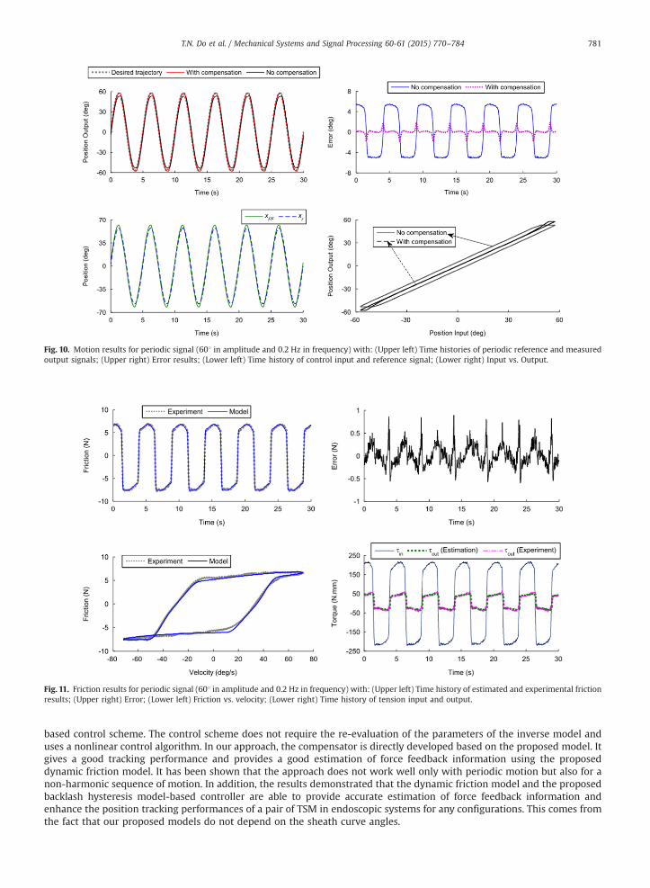
Fig. 10. Motion results for periodic signal (601 in amplitude and 0.2 Hz in frequency) with: (Upper left) Time histories of periodic reference and measuredoutput signals; (Upper right) Error results; (Lower left) Time history of control input and reference signal; (Lower right) Input vs. Output.
Fig. 11. Friction results for periodic signal (601 in amplitude and 0.2 Hz in frequency) with: (Upper left) Time history of estimated and experimental frictionresults; (Upper right) Error; (Lower left) Friction vs. velocity; (Lower right) Time history of tension input and output.
T.N. Do et al. / Mechanical Systems and Signal Processing 60-61 (2015) 770–784 781
based control scheme. The control scheme does not require the re-evaluation of the parameters of the inverse model anduses a nonlinear control algorithm. In our approach, the compensator is directly developed based on the proposed model. Itgives a good tracking performance and provides a good estimation of force feedback information using the proposeddynamic friction model. It has been shown that the approach does not work well only with periodic motion but also for anon-harmonic sequence of motion. In addition, the results demonstrated that the dynamic friction model and the proposedbacklash hysteresis model-based controller are able to provide accurate estimation of force feedback information andenhance the position tracking performances of a pair of TSM in endoscopic systems for any configurations. This comes fromthe fact that our proposed models do not depend on the sheath curve angles.
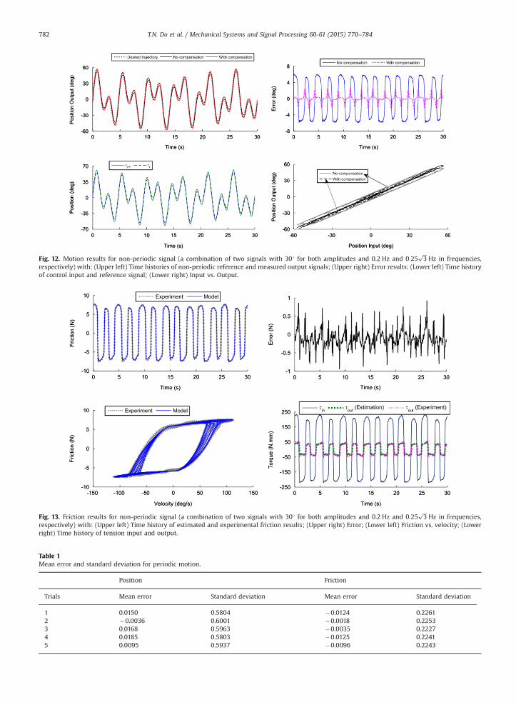
Fig. 12. Motion results for non-periodic signal (a combination of two signals with 301 for both amplitudes and 0.2 Hz and 0:25ffiffiffi3
pHz in frequencies,
respectively) with: (Upper left) Time histories of non-periodic reference and measured output signals; (Upper right) Error results; (Lower left) Time historyof control input and reference signal; (Lower right) Input vs. Output.
Fig. 13. Friction results for non-periodic signal (a combination of two signals with 301 for both amplitudes and 0.2 Hz and 0:25ffiffiffi3
pHz in frequencies,
respectively) with: (Upper left) Time history of estimated and experimental friction results; (Upper right) Error; (Lower left) Friction vs. velocity; (Lowerright) Time history of tension input and output.
Table 1Mean error and standard deviation for periodic motion.
Position Friction
Trials Mean error Standard deviation Mean error Standard deviation
1 0.0150 0.5804 �0.0124 0.22612 �0.0036 0.6001 �0.0018 0.22533 0.0168 0.5963 �0.0035 0.22274 0.0185 0.5803 �0.0125 0.22415 0.0095 0.5937 �0.0096 0.2243
T.N. Do et al. / Mechanical Systems and Signal Processing 60-61 (2015) 770–784782
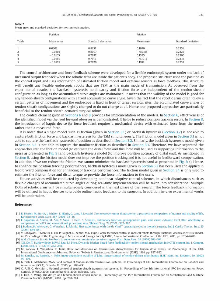
Table 2Mean error and standard deviation for non-periodic motion.
Position Friction
Trials Mean error Standard deviation Mean error Standard deviation
1 0.0602 0.8157 0.1070 0.23512 �0.0804 0.8007 �0.0188 0.23253 �0.0165 0.7937 0.1335 0.23604 �0.0659 0.7917 �0.1015 0.23185 �0.0878 0.7829 0.1187 0.2231
T.N. Do et al. / Mechanical Systems and Signal Processing 60-61 (2015) 770–784 783
The control architecture and force feedback scheme were developed for a flexible endoscopic system under the lack ofmeasured output feedback when the robotic arms are inside the patient's body. The proposed structure used the position asthe control input and uses information of estimated friction model and external sensors as force feedback. This structurewill benefit any flexible endoscopic robots that use TSM as the main mode of transmission. As observed from theexperimental results, the backlash hysteresis nonlinearity and friction force are independent of the tendon-sheathconfiguration as long as the accumulated curve angles are maintained. It means that the validity of the model is good forany tendon-sheath configurations with a fixed accumulated curve angle. Given the fact that the robotic arms often follow acertain patterns of movement and the endoscope is fixed in front of target surgical sites, the accumulated curve angles oftendon-sheath configurations are slightly changed or do not change at all. Hence, our proposed approaches are particularlybeneficial to the tendon-sheath actuated surgical robots.
The control element given in Sections 6 and 8 provides for implementation of the models. In Section 6, effectiveness ofthe identified model via the feed forward observer is demonstrated. It helps to reduce position tracking errors. In Section 8,the introduction of haptic device for force feedback requires a mechanical device with estimated force from the modelrather than a measured force.
It is noted that a single model such as friction (given in Section 3.1) or backlash hysteresis (Section 3.2) is not able tocapture both friction force and backlash hysteresis for the TSM simultaneously. The friction model given in Section 3.1 is notable to capture the backlash hysteresis of position as described in Section 3.2. Similarly, the backlash hysteresis model givenin Section 3.2 is not able to capture the nonlinear friction as described in Section 3.1. Therefore, we have separated theapproaches into the friction model (to estimate the distal force and this force will be used as supporting information to theusers as presented in Fig. 9) and backlash hysteresis model (to improve position accuracy of distal end). As mentioned inSection 6, using the friction model does not improve the position tracking and it is not useful in feedforward compensation.In addition, if we can reduce the friction, we cannot minimize the backlash hysteresis band as presented in Fig. 3(a). Hence,to enhance the position tracking performances, backlash hysteresis model given in Section 3.2 has been used and applied infeedforward compensation for enhancing of tracking performances. The friction model given in Section 3.1 is only used toestimate the friction force and distal torque to provide the force information to the users.
Future activities will be conducted by developing nonlinear adaptive control schemes, in which disturbances such asflexible changes of accumulated curve angles during real-time implementation will be taken into consideration. MultipleDOFs of robotic arms will be simultaneously considered in the next phase of the research. The force feedback informationwill be utilized in haptic devices to provide online haptic feedback to the surgeons. In addition, in-vivo experimental workswill be undertaken.
References
[1] R. Förster, M. Storck, J. Schäfer, E. Hönig, G. Lang, F. Liewald, Thoracoscopy versus thoracotomy: a prospective comparison of trauma and quality of life,Langenbeck's Arch. Surg. 387 (2002) 32–36.
[2] I. Nagahiro, A. Andou, M. Aoe, Y. Sano, H. Date, N. Shimizu, Pulmonary function, postoperative pain, and serum cytokine level after lobectomy: acomparison of VATS and conventional procedure, Ann. Thorac. Surg. 72 (2001) 362–365.
[3] J. Bodner, H. Wykypiel, G. Wetscher, T. Schmid, First experiences with the da Vinci™ operating robot in thoracic surgery, Eur. J. Cardio-Thorac. Surg. 25(2004) 844–851.
[4] Y. Kobayashi, P. Moreira, C. Liu, P. Poignet, N. Zemiti, M.G. Fujie, Haptic feedback control in medical robots through fractional viscoelastic tissue model,in: Proceedings of the Engineering in Medicine and Biology Society,EMBC, Annual International Conference of the IEEE, 2011, pp. 6704–6708.
[5] A.M. Okamura, Haptic feedback in robot-assisted minimally invasive surgery, Curr. Opin. Urol. 19 (2009) 102–107.[6] T.N. Do, T. Tjahjowidodo, M.W.S. Lau, S.J. Phee, Dynamic friction-based force feedback for tendon-sheath mechanism in NOTES system, Int. J. Comput.
Electr. Eng. 6 (3) (2014) 252–258.[7] M. Kaneko, T. Yamashita, K. Tanie, Basic considerations on transmission characteristics for tendon drive robots, in: Proceedings of the Fifth
International Conference on Advanced Robotics, 'Robots in Unstructured Environments' (ICAR), 1991, pp. 827–832.[8] M. Kaneko, W. Paetsch, H. Tolle, Input-dependent stability of joint torque control of tendon-driven robot hands, IEEE Trans. Ind. Electron. 39 (1992)
96–104.[9] G. Palli, C. Melchiorri, Model and control of tendon-sheath transmission systems, in: Proceedings of IEEE International Conference on Robotics and
Automation (ICRA), Orlando, FL, 2006, pp. 988–993.[10] G. Palli, C. Melchiorri, Optimal control of tendon-sheath transmission systems, in: Proceedings of the 8th International IFAC Symposium on Robot
Control, SYROCO 2006, September 6–8, 2006, Bologna, Italy.[11] F. Tian, X. Wang, The design of a tendon-sheath-driven robot, in: Proceedings of the 15th International Conference on Mechatronics and Machine
Vision in Practice (M2VIP), 2008, pp. 280–284.
T.N. Do et al. / Mechanical Systems and Signal Processing 60-61 (2015) 770–784784
[12] L. Chen, X. Wang, Modeling of the tendon-sheath actuation system, in: Proceedings of the 19th International Conference on Mechatronics andMachine Vision in Practice (M2VIP), Auckland, 2012, pp. 489–494.
[13] S.C. Low, S.J. Phee, P. Valdastri, A. Menciassi, P. Dario, Tendon sheath analysis for estimation of distal end force and elongation, in: Proceedings of IEEE/ASME International Conference on Advanced Intelligent Mechatronics (AIM), 2009, pp. 332–337.
[14] V. Agrawal, W.J. Peine, B. Yao, Modeling of a closed loop cable-conduit transmission system, in: Proceedings of IEEE International Conference onRobotics and Automation (ICRA), Pasadena, CA, 2008, pp. 3407–3412.
[15] V. Agrawal, W.J. Peine, B. Yao, Modeling of transmission characteristics across a cable-conduit system, IEEE Trans. Robotics 26 (2010) 914–924.[16] V. Agrawal, W.J. Peine, B. Yao, S. Choi, Control of cable actuated devices using smooth backlash inverse, in: Proceedings of IEEE International
Conference on Robotics and Automation (ICRA), 2010, pp. 1074–1079.[17] S.B. Kesner, R.D. Howe, Design and control of motion compensation cardiac catheters, in: Proceedings of IEEE International Conference on Robotics and
Automation (ICRA), 2010, pp. 1059–1065.[18] S.B. Kesner, R.D. Howe, Position control of motion compensation cardiac catheters, IEEE Trans. Robotics 27 (2011) 1045–1055.[19] B. Bardou, F. Nageotte, P. Zanne, M. de Mathelin, Improvements in the control of a flexible endoscopic system, in: Proceedings of IEEE International
Conference on Robotics and Automation (ICRA), 2012, pp. 3725–3732.[20] H. Olsson, K.J. Åström, C. Canudas De Wit, M. Gäfvert, P. Lischinsky, Friction models and friction compensation, Eur. J. Control 4 (1998) 176–195.[21] T. Tjahjowidodo, F. Al-Bender, H. Van Brussel, W. Symens, Friction characterization and compensation in electro-mechanical systems, J. Sound Vib. 308
(2007) 632–646.[22] T. Vo-Minh, T. Tjahjowidodo, H. Ramon, H. Van Brussel, A new approach to modeling hysteresis in a pneumatic artificial muscle using the Maxwell-slip
model, IEEE/ASME Trans. Mechatron. 16 (2011) 177–186.[23] M. Tri Vo, T. Tjahjowidodo, H. Ramon, H. Van Brussel, Non-local memory hysteresis in a pneumatic artificial muscle (PAM), in: MED '09, Proceedings of
the 17th Mediterranean Conference on Control and Automation, 2009, pp. 640–645.[24] K. Johanastrom, C. Canudas-de-Wit, Revisiting the LuGre friction model, IEEE Control Syst. Mag. 28 (2008) 101–114.[25] F. Ikhouane, J. Rodellar, Systems with Hysteresis: Analysis, Identification and Control Using the Bouc–Wen Model, John Wiley & Sons, Ltd., Hoboken,
2007.[26] F. Ikhouane, J. Hurtado, J. Rodellar, Variation of the hysteresis loop with the Bouc–Wen model parameters, Nonlinear Dyn. 48 (2007) 361–380.[27] R. Zglimbea, V. Finca, E. Greaban, M. Constantin, Identification of systems with friction via distributions using the modified friction LuGre model, in:
Proceedings of the 13th WSEAS International Conference on Systems, ICS'09, 2009, pp. 579–584.[28] V. Hassani, T. Tjahjowidodo, T.N. Do, A survey on hysteresis modeling, identification and control, Mech. Syst. Signal Process. 49 (2014) 209–233.[29] T. Tjahjowidodo, F. Al-Bender, H. Van Brussel, Experimental dynamic identification of backlash using skeleton methods, Mech. Syst. Signal Process. 21
(2) (2007) 959–972.[30] T. Tjahjowidodo, F. Al-Bender, H. Van Brussel, Quantifying chaotic responses of mechanical systems with backlash component, Mech. Syst. Signal
Process. 21 (2) (2007) 973–993.[31] M.L. Hodgdon, Applications of a theory of ferromagnetic hysteresis, IEEE Trans. Magn. 24 (1988) 218–221.[32] B.D. Coleman, M.L. Hodgdon, A constitutive relation for rate-independent hysteresis in ferromagnetically soft materials, Int. J. Eng. Sci. 24 (1986)
897–919.[33] C.Y. Su, Y. Stepanenko, J. Svoboda, T.P. Leung, Robust adaptive control of a class of nonlinear systems with unknown backlash-like hysteresis, IEEE
Trans. Autom. Control 45 (2000) 2427–2432.[34] N.J. Ahmad, H.K. Ebraheem, M.Q. Qasem, Global asmptotic stability for systems with friction and input backlash, in: Proceedings of the 2005 IEEE
International Symposium onIntelligent Control, Mediterrean Conference on Control and Automation, 2005, pp. 212–218.[35] X. Qingsong, L. Yangmin, Modeling and control of rate-dependent hysteresis for a piezo-driven micropositioning stage, in: Proceedings of 2011 IEEE
International Conference on Robotics and Automation (ICRA), Shanghai, China, 2011, pp. 1670–1675.[36] M. Rakotondrabe, Bouc–Wen modeling and inverse multiplicative structure to compensate hysteresis nonlinearity in piezoelectric actuators, IEEE
Trans. Autom. Sci. Eng. 8 (2011) 428–431.[37] D.H. Wang, W. Zhu, Q. Yang, Linearization of stack piezoelectric ceramic actuators based on Bouc–Wen model, J. Intell. Mater. Syst. Struct. 22 (2011)
401–413.[38] C.-J. Lin, P.-T. Lin, Tracking control of a biaxial piezo-actuated positioning stage using generalized Duhem model, Comput. Math. Appl. 64 (2012)
766–787.[39] T.N. Do, T. Tjahjowidodo, M.W.S. Lau, T. Yamamoto, S.J. Phee, Hysteresis modeling and position control of tendon-sheath mechanism in flexible
endoscopic systems, Mechatronics 24 (2014) 12–22.[40] T.N. Do, T. Tjahjowidodo, M.W.S. Lau, S.J. Phee, An investigation of friction-based tendon sheath model appropriate for control purposes, Mech. Syst.
Signal Process. 42 (2013) 97–114.[41] P. Ikhouane, J. Rodellar, On the hysteretic Bouc–Wen model. Part I. Forced limit cycle characterization, Nonlinear Dyn. 42 (2005) 63–78.[42] M. Ismail, F. Ikhouane, J. Rodellar, The Hysteresis Bouc–Wen Model, a Survey, Arch. Comput. Methods Eng. 16 (2009) 161–188.[43] G. Tao, P.V. Kokotovic, Adaptive control of system with unknown output backlash, IEEE Trans. Autom. Control 40 (1995) 326–330.[44] G. Tao, P.V. Kokotovic, Adaptive control of systems with backlash, Automatica 29 (1993) 323–335.[45] G. Tao, P.V. Kokotovic, Continuous-time adaptive control of systems with unknown backlash, IEEE Trans. Autom. Control 40 (1995) 1083–1087.[46] T.N. Do, T. Tjahjowidodo, M.W.S. Lau, S.J. Phee, Nonlinear modeling and parameter identification of dynamic friction model in tendon sheath for
flexible endoscopic systems, in: ICINCO 2013–Proceedings of the 10th International Conference on Informatics in Control, Automation and Robotics,Reykjavik, Iceland, vol. 2, (2013) pp. 5–10.
[47] T.N. Do, T. Tjahjowidodo, M.W.S. Lau, S.J. Phee, Dynamic friction model for tendon-sheath actuated surgical robots: modelling and stability analysis, in:the Proceedings of 3rd IFToMM International Symposium on Robotics and Mechatronics, Singapore, 2013, pp. 302–311.
Copyright © 2022 FDOKUMEN