Nonlinear dynamic analysis of cylindrical roller bearing with flexible rings
23
Nonlinear dynamic analysis of cylindrical roller bearing with flexible rings Alexandre Leblanc a,∗ Daniel Nelias a Cyril Defaye a a LaMCos UMR CNRS 5259 INSA Lyon 69621 Villeurbanne FRANCE Abstract A nonlinear plan dynamic model for cylindrical bearings has been developed, predict- ing the interaction forces between the retainers and the rolling elements. Roller-race contacts are analyzed in detail and resulting forces and moments are determined. An elastohydrodynamic lubrication (EHL) model provides the traction components while a hydrodynamic formulation is used for the roller-cage interactions. Structural deformations of the rings are included in the geometrical equations linking the rela- tive displacements between rings. The Newmark type implicit integration technique coupled with the Newton-Raphson method is used to solve the differential equation system iteratively. Time displacements and theirs FFT are used to illustrate and elucidate the diversity of the system response. Computations performed when considering the structural deformations of the rings show a low frequency shift, as higher harmonics are attenuated while the first are more pronounced. With an unbalanced rotor, the ball pass frequency (BPF) is mod- ulated with this perturbation leading to an aperiodic response. This is particularly true for the counter-rotating bearing investigated. Finally, results for different cage materials show a significant influence only on the cage center location, whereas the inertia moment of the cage is of little impact on the global dynamics behavior. Key words: Roller Bearing; Flexible Ring; High Speed; Nonlinear Dynamical Systems PACS: 46.55.+d, 05.45.-a ∗ Corresponding author. Email addresses: [email protected] (Alexandre Leblanc), [email protected] (Daniel Nelias). Preprint submitted to Elsevier 11 March 2009
Transcript of Nonlinear dynamic analysis of cylindrical roller bearing with flexible rings

Nonlinear dynamic analysis of cylindrical
roller bearing with flexible rings
Alexandre Leblanc a,∗ Daniel Nelias a Cyril Defaye a
aLaMCosUMR CNRS 5259
INSA Lyon69621 Villeurbanne FRANCE
Abstract
A nonlinear plan dynamic model for cylindrical bearings has been developed, predict-ing the interaction forces between the retainers and the rolling elements. Roller-racecontacts are analyzed in detail and resulting forces and moments are determined.An elastohydrodynamic lubrication (EHL) model provides the traction componentswhile a hydrodynamic formulation is used for the roller-cage interactions. Structuraldeformations of the rings are included in the geometrical equations linking the rela-tive displacements between rings. The Newmark type implicit integration techniquecoupled with the Newton-Raphson method is used to solve the differential equationsystem iteratively. Time displacements and theirs FFT are used to illustrate andelucidate the diversity of the system response.
Computations performed when considering the structural deformations of the ringsshow a low frequency shift, as higher harmonics are attenuated while the first aremore pronounced. With an unbalanced rotor, the ball pass frequency (BPF) is mod-ulated with this perturbation leading to an aperiodic response. This is particularlytrue for the counter-rotating bearing investigated. Finally, results for different cagematerials show a significant influence only on the cage center location, whereas theinertia moment of the cage is of little impact on the global dynamics behavior.
Key words:Roller Bearing; Flexible Ring; High Speed; Nonlinear Dynamical SystemsPACS: 46.55.+d, 05.45.-a
∗ Corresponding author.Email addresses: [email protected] (Alexandre Leblanc),
[email protected] (Daniel Nelias).
Preprint submitted to Elsevier 11 March 2009
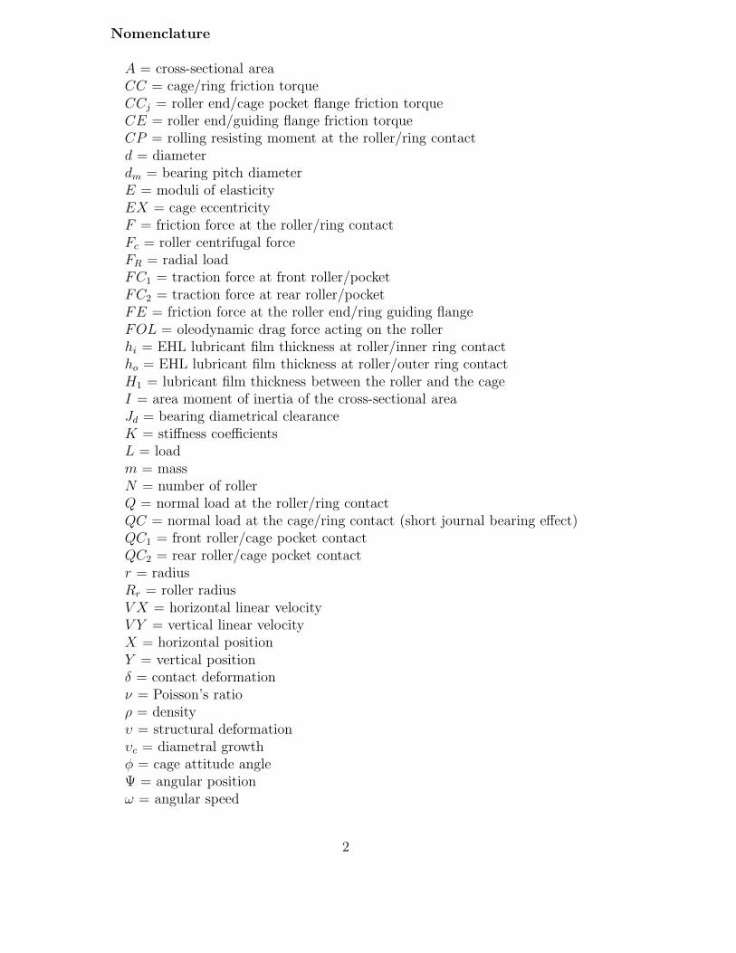
Nomenclature
A = cross-sectional areaCC = cage/ring friction torqueCCj = roller end/cage pocket flange friction torqueCE = roller end/guiding flange friction torqueCP = rolling resisting moment at the roller/ring contactd = diameterdm = bearing pitch diameterE = moduli of elasticityEX = cage eccentricityF = friction force at the roller/ring contactFc = roller centrifugal forceFR = radial loadFC1 = traction force at front roller/pocketFC2 = traction force at rear roller/pocketFE = friction force at the roller end/ring guiding flangeFOL = oleodynamic drag force acting on the rollerhi = EHL lubricant film thickness at roller/inner ring contactho = EHL lubricant film thickness at roller/outer ring contactH1 = lubricant film thickness between the roller and the cageI = area moment of inertia of the cross-sectional areaJd = bearing diametrical clearanceK = stiffness coefficientsL = loadm = massN = number of rollerQ = normal load at the roller/ring contactQC = normal load at the cage/ring contact (short journal bearing effect)QC1 = front roller/cage pocket contactQC2 = rear roller/cage pocket contactr = radiusRr = roller radiusV X = horizontal linear velocityV Y = vertical linear velocityX = horizontal positionY = vertical positionδ = contact deformationν = Poisson’s ratioρ = densityυ = structural deformationυc = diametral growthφ = cage attitude angleΨ = angular positionω = angular speed
2

Subscripts
i = inner ringo = outer ringc = cagej = roller numberR = roller
1 INTRODUCTION
The dynamical analysis of a rotor system supported by rolling bearings is ofprime importance in many engineering applications. Rotors are often subjectedto either stationary radial load or periodic forces due to unbalanced mass. Thenon-linear behavior of rolling bearings should be considered carefully whenlooking at the shaft trajectory or the dynamic response of the rotor-bearingsystem. The numerical simulation of a rolling bearing submitted to transientloading will improve our understanding of the dynamic response of the wholesystem. It is now clear that, when a roller bearing is radially loaded, part ofthe rollers are unloaded as they whirl in orbit. It is then interesting to look atthe behavior of each roller when it enters and exits the loading zone. Factorssuch as the interactions between the cage and the rollers or the irregulartraction characteristics further act on the motion of the bearing elements,leading sometimes to instabilities. Beyond these phenomena, responses of nonlinear systems often show unexpected behavior and are extremely sensitive toinitial conditions, like clearance or excitation by unbalanced rotors.
Until the late 70’s, most of the analytical simulations of rolling-element bear-ings were restricted to quasi-static models which consist of a set of non-linearalgebraic equations solved by standard iteration methods. Walter [1] was thefirst to develop an analytical model for ball bearing and cage dynamics. Later,Gupta [2,3] modified and extended this analysis to other types of rolling ele-ment bearings, setting the basis of the well-known computer code ADORE c©,which has been used to validate the model presented in this paper. As a resultof the increase in capacities, the number of publications in the field has grownsignificantly over the years.
A lot of research has been conducted on three-dimensional modeling [2,4–7],the effects of geometrical imperfections [8,9] and experimental results [10,11].More recently, Lee et al. [12] derived a theoretical model for the coupling-rotor-ball bearing systems with misalignment and showed the whirling orbits’tendency to collapse with increasing angular misalignment. Tiwari et al. stud-ied the nonlinear behaviors of a balanced [13] or unbalanced [14] rotor dueto the effect of internal clearance of the ball bearing. Harsha et al. [15] simu-
3

cage
roller
outer ring
inner ringdm dc dR
Fig. 1. Schematic diagram of a roller bearing.
lated some dynamic responses for rotors supported by ball bearings, using a2 DOF model with clearance and waviness. Similar investigations have beenconducted with a 5 DOF transient dynamic model considering the centrifugalforce and gyroscopic moment of the ball by Changqing et al. [16]. For a rotat-ing system supported by bearings, the impact of ball waviness on the resultingsideband frequencies has been investigated by Jang et al. [17].
This non-exhaustive list of dynamic analysis for rolling-element demonstratesthe variety of phenomena that may affect the vibration behavior of such sys-tems. The present paper contains a two dimensional roller bearing dynamicanalysis which takes into account some of the forsaken parameters: the effectsof unbalanced rotor forces, cage materials and counter-rotating motions areinvestigated while also considering the structural deformations of the inner-and outer-rings.
2 THE PROBLEM FORMULATION
A schematic diagram of roller bearing is shown in Fig. 1. The elastic deflectionat the contact between a crowned roller and a ring was determined by Palm-gren [18]. This local or contact deformation is independent of the structuredeformation.
2.1 Structural deformations
The proposed solution is an extension of the model proposed by Cavallaro etal. model [19]. The global or structural deformation has two contributions: auniform centrifugal expansion and the load distribution among rollers. Bothare used to obtain the operating radial clearance i.e. the difference between
4
θ
υ (θ)
ΨjWj
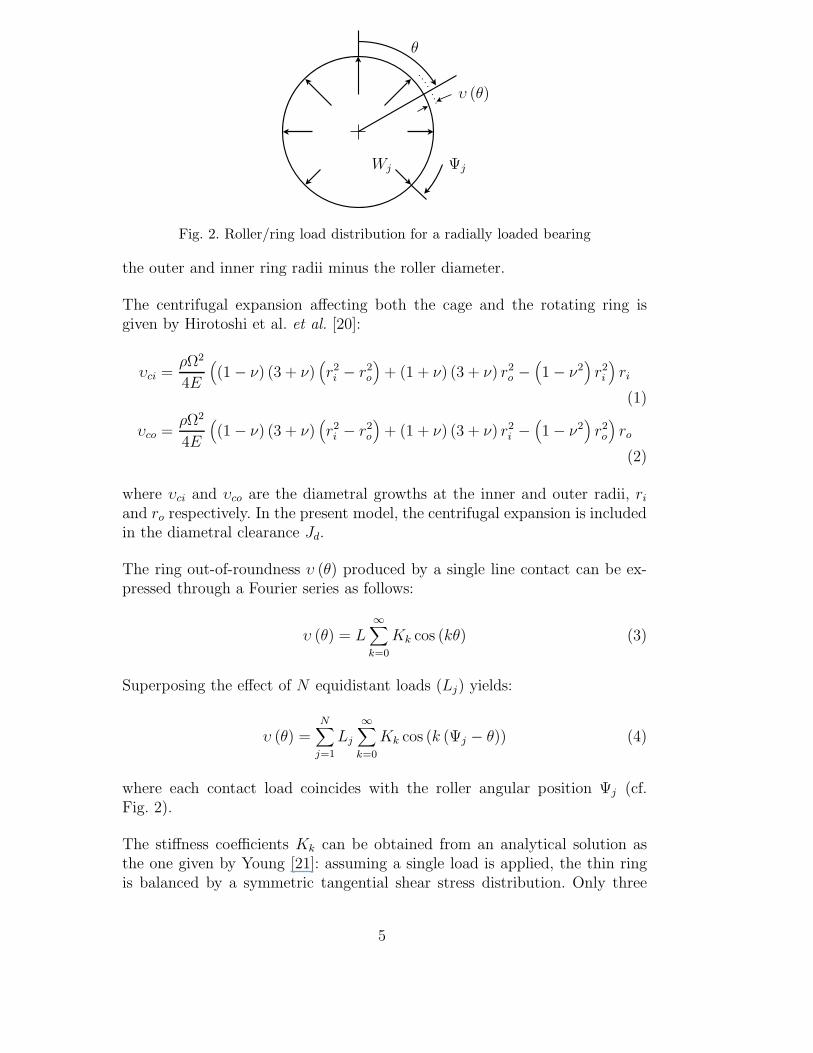
Fig. 2. Roller/ring load distribution for a radially loaded bearing
the outer and inner ring radii minus the roller diameter.
The centrifugal expansion affecting both the cage and the rotating ring isgiven by Hirotoshi et al. et al. [20]:
υci =ρΩ2
4E
((1 − ν) (3 + ν)
(r2i − r2
o
)+ (1 + ν) (3 + ν) r2
o −(1 − ν2
)r2i
)ri
(1)
υco =ρΩ2
4E
((1 − ν) (3 + ν)
(r2i − r2
o
)+ (1 + ν) (3 + ν) r2
i −(1 − ν2
)r2o
)ro
(2)
where υci and υco are the diametral growths at the inner and outer radii, ri
and ro respectively. In the present model, the centrifugal expansion is includedin the diametral clearance Jd.
The ring out-of-roundness υ (θ) produced by a single line contact can be ex-pressed through a Fourier series as follows:
υ (θ) = L∞∑
k=0
Kk cos (kθ) (3)
Superposing the effect of N equidistant loads (Lj) yields:
υ (θ) =N∑
j=1
Lj
∞∑k=0
Kk cos (k (Ψj − θ)) (4)
where each contact load coincides with the roller angular position Ψj (cf.Fig. 2).
The stiffness coefficients Kk can be obtained from an analytical solution asthe one given by Young [21]: assuming a single load is applied, the thin ringis balanced by a symmetric tangential shear stress distribution. Only three
5

stiffness coefficients are then required to obtain the ring deformations:
υ (θ) = L (K0 + K1 cos θ + K2 cos 2θ) (5)
Although this formula leads to a good approximation of the shape of the innerring when subjected to a static load, it fails completely for a set of equally, oralmost identically loaded rollers. This is the case for the outer ring, for high-speed application, since the rollers are all loaded at least by the centrifugalforce.
For a thin ring submitted to N equivalent (Fc) loads, several analytical solu-tions are available. Yhland’s formulation is used here (as reported by Wens-ing [22]). This solution, valid at any point of the ring, takes into account theflexural and the extensional deformations:
υY (θ) =Fc × N × ro
2πE × Ao+
Fc × N × r3o
πE × Io
∞∑q=1
1((qN)2 − 1
)2 cos (qNθ) (6)
For the complete loading of the outer ring, this yields:
υ (θ) =N∑
j=1
(Qoj − Fc)2∑
n=0
Kn cos (n(φj − θ)) + υY (θ) (7)
2.2 Equations of motion
The roller bearing behavior is described by solving a set of dynamic, equilib-rium and geometric non-linear equations, including both cage and lubricanteffects. The problem is planar, so only pure radial loading is considered, as-suming perfect geometry for the rolling elements and no ring misalignment.
Figure 3 shows a roller loaded at the roller/race contact (Q), at the front orrear roller/cage pocket contact (QC1 and QC2 respectively), and submittedto a centrifugal force (Fc). Dry or lubricated traction forces at the roller/raceand roller/pocket (F , FC1 and FC2 respectively) are of primary importancein roller equilibrium. A resisting torque (CP ) due to an asymmetric hydrody-namic pressure field and the oleodynamic drag force (FOL) are considered.Due to small internal clearances needed for high-speed operation, friction ef-fects at the roller end/cage pocket (friction torque CC) and roller end/guidingflange (traction force FE and friction torque CE) are also considered.
In addition to the roller/cage interactions, the contact between the cage andthe guiding ring surfaces introduces a normal load (QC) and a friction torque(CC) linked to the cage attitude angle (φ) and eccentricity (EX), through ashort journal bearing model (see Fig. 4).
6

Oj
Fc
FOL
FC2j
QC2j
QijFij
CCjFC1j
QC1j
CEj
FEj
Qoj
Foj
CPoj
CPij
Fig. 3. Loads acting on a roller
FC11
FC21
FC1jFC2j
ψj
QCo
QCi
CCi ωc
φ
χ
(QC1 − QC2)j
(QC1 − QC2)1
CCo
Fig. 4. Loads acting on the cage
Finally, the roller/ring reaction forces balance the inner ring. See Cavallaropaper [19] for details on force models used
7
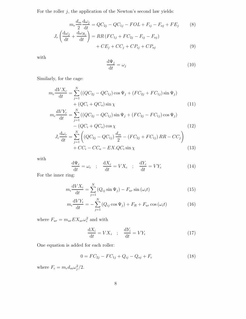
For the roller j, the application of the Newton’s second law yields:
mrdm
2
dωj
dt= QC2j − QC1j − FOL + Fij − Foj + FEj (8)
Jr
(dωj
dt+
dωRj
dt
)= RR (FC1j + FC2j − Fij − Foj)
+ CEj + CCj + CPij + CPoj (9)
withdΨj
dt= ωj (10)
Similarly, for the cage:
mcdV Xc
dt=
N∑j=1
((QC2j − QC1j) cos Ψj + (FC2j + FC1j) sin Ψj)
+ (QCi + QCo) sin χ (11)
mcdV Yc
dt=
N∑j=1
((QC2j − QC1j) sin Ψj + (FC2j − FC1j) cos Ψj)
− (QCi + QCo) cos χ (12)
Jcdωc
dt=
N∑j=1
((QC2j − QC1j)
dm
2− (FC2j + FC1j) RR − CCj
)
+ CCi − CCo − EX.QCi sin χ (13)
withdΨc
dt= ωc ;
dXc
dt= V Xc ;
dYc
dt= V Yc (14)
For the inner ring:
midV Xi
dt=
N∑j=1
(Qij sin Ψj) − Fur sin (ωit) (15)
midV Yi
dt= −
N∑j=1
(Qij cos Ψj) + FR + Fur cos (ωit) (16)
where Fur = murEXurω2i and with
dXi
dt= V X i ;
dYi
dt= V Yi (17)
One equation is added for each roller:
0 = FC2j − FC1j + Qij − Qoj + Fc (18)
where Fc = mrdmω2j /2.
8

Ψj
Xi
Yi Oi
Oo
Fr
Fur
inner ring
outer ring
roller
hij − Jd
4
hoj − Jd
4
−δij − υij
−δoj − υoj
Fig. 5. Relative displacement between the inner and the outer ring centers
X1 Y1Oc (Xc, Yc)
X YO
tj
nj
OjH1j
Ψcj
Ψj
cage (front)
cage (rear)
roller
Fig. 6. Lubricant thickness between the roller and the cage
2.3 Geometry considerations
Two geometric relations must be added to describe the relative displacementbetween the inner and the outer ring centers (Fig. 5) and the lubricant filmthickness between the roller and the cage pocket. The first relation includesthe EHL film thickness at the roller/race contacts h, the contact deformationsδ, the radial clearance Jd and the structural deformations υ:
Jd
2+ δij + δoj − hij − hoj + υij + υoj = Yi cos Ψj − Xi sin Ψj (19)
The lubricant film between the roller and the cage (Fig. 6) is given by :
9

0 0.5 1 1.5 2
x 104
60
70
80
90
100
Inner ring speed (tr/min)
Cor
rela
tion
(%)
Inner ringCage
Fig. 7. Correlation of the radial displacements predicted by the present model andADORE c©
H1j =dm
2
(Ψcj − arctan
(2Rr
dm
)
− arctan
⎛⎝ Xc
EXcos Ψcj + Yc
EXsin Ψcj
Rc
EX−(
Xc
EXsin Ψcj − Yc
EXcos Ψcj
) − Ψj
⎞⎠⎞⎠ (20)
where Ψcj = Ψc + 2π(j − 1)/N .
2.4 Validations
The basic testing of the present code has been performed with ADORE c© [3]and with the research model used by Ghaisas et al. in [23]. Figure 7 showsthe correlation coefficients for the radial displacements predicted by Gupta’ssoftware and our model applied on a perfect roller bearing with radial loading(Table 8-3 of [3]). High rate of agreement is achieved for the inner ring trajec-tories and for the speed range investigated. The cage behavior still correctlypredicted although cage interactions differ somewhat for the two models.
3 RESULTS
The equations of motion are solved using a modified Newmark-β method toinvestigate the effects of internal clearance, ring asymmetry and cage material.A large number of revolutions is computed to ensure a steady-state response.The displacement and velocity of the bearing elements are recorded at eachtime step. The characteristics of the roller bearing investigated are given inTable 1.
10

Number of rollers N = 28Pitch diameter dm (mm) = 144.5Cage diameter dc (mm) = 140.7
Roller diameter dR (mm) = 12Inner shaft+ring thickness (mm) 41Outer shaft+ring thickness (mm) 30
Free diametral clearance Jd (mm) = 6e-2Race and roller material = M50
Cage material: M50 or PEEKCage centering: Inner ring
Oil: Mobil Oil Jet II (MIL-L-23699)
Table 1Bearing parameters
3.1 Initial conditions
For nonlinear systems, different initial conditions lead to different behaviorsand solutions. The choice of time step δt is a key point: it should be smallenough to get an accurate numerical solution but large enough to avoid signif-icant truncation errors and keep the computational solution reasonable. Here,δt is set to 5 − 10 μs and at time t = 0, the initial bearing parameters arethose given by the quasi-static equilibrium.
3.2 Flexible rings
Figure 8 shows the rotor mass center for rigid (left) or flexible (right) rings. Asthe average speed of a roller around the outer race is equal to cage speed ωc,the rotor is excited at the frequency of Nωc, known as ”ball” pass frequency(BPF). Here the BPF is equal to 960 Hz. For the rigid ring case, the appliedradial load is supported by a few rollers located in a narrow angular region,depending only on the elastic deflection at the roller/raceway contact. Thesepeak-shaped load profiles induce the strong second harmonic of BPF for thehorizontal displacement. For the vertical displacement, a third harmonic con-tributes to the response. This frequency is directly linked to the short loadingperiod of the rollers. With the flexible rings, higher harmonics disappear asthe load period increases while the contact pressure distribution is flattened(cf. Fig. 9).
11

0 500 1000 1500 2000 2500 30000
0.1
0.2
0.3
Frequency (Hz)
Am
plitu
de (
μm)
Balanced rotor − Rigid rings
0 500 1000 1500 2000 2500 30000
0.01
0.02
0.03
0.04
Frequency (Hz)
Am
plitu
de (
μm)
−1 −0.5 0 0.5 1−10
−5
0
5
10
Horizontal displacement ( μm )
Hor
izon
tal v
eloc
ity (
mm
/s )
54.35 54.4 54.45 54.5 54.55 54.6 54.65−2
−1
0
1
2
Vertical displacement ( μm )
Ver
tical
vel
ocity
( m
m/s
)
0 500 1000 1500 2000 2500 30000
0.1
0.2
0.3
Frequency (Hz)
Am
plitu
de (
μm)
Balanced rotor − Flexible rings
0 500 1000 1500 2000 2500 30000
0.01
0.02
0.03
0.04
Frequency (Hz)
Am
plitu
de (
μm)
−1 −0.5 0 0.5 1−10
−5
0
5
10
Horizontal displacement ( μm )
Hor
izon
tal v
eloc
ity (
mm
/s )
82.7 82.75 82.8 82.85 82.9 82.95 83−2
−1
0
1
2
Vertical displacement ( μm )
Ver
tical
vel
ocity
( m
m/s
)
BPF
2 BPF
3 BPF
Horizontal displacement Horizontal displacement
Vertical displacement Vertical displacement
Fig. 8. Inner ring displacements at 4500 rpm for Fr=3000 daN with rigid and flexiblerings - balanced rotor
3.3 Stability analysis
In the Fig. 8, a band of low frequency is visible in each of the displacementresponses. It can be suspected at first to be the result of numerical errors. To
12

time
load
rigid ringsflexible rings
Fig. 9. Roller load shape
Fig. 10. Campbell diagram for the radial displacement of the inner ring - rigid rings
dispel these errors and to find any critical values leading to dramatic bearingbehavior, a stability analysis is performed. In Figures 10 and 11 the Campbelldiagrams are shown for the radial displacements of the inner ring of Fig. 8 forrotating speed from 1,000 to 20,000 rpm with 100 rpm step.
Aside the BPF harmonics found previously, two instability rotating speedsareas are found in the investigated range. For the rigid case shows in theFig. 10, the first instability area is around 7 krpm and the second around 14krpm. A radial mode is also slightly apparent at 3kHz while the lower band offrequencies contains several harmonics linked to the cage (fcage), roller (froller)and inner ring (fIR) frequencies. The flexibility of the rings (Fig. 11) shifts the
13
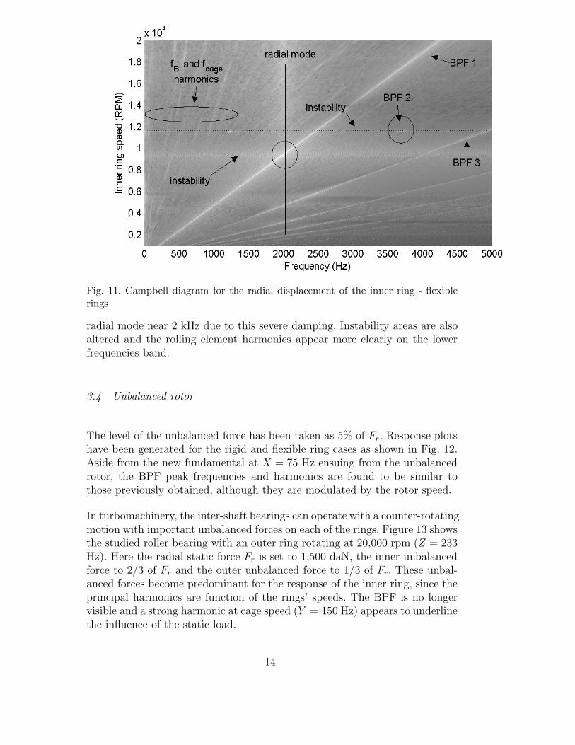
Fig. 11. Campbell diagram for the radial displacement of the inner ring - flexiblerings
radial mode near 2 kHz due to this severe damping. Instability areas are alsoaltered and the rolling element harmonics appear more clearly on the lowerfrequencies band.
3.4 Unbalanced rotor
The level of the unbalanced force has been taken as 5% of Fr. Response plotshave been generated for the rigid and flexible ring cases as shown in Fig. 12.Aside from the new fundamental at X = 75 Hz ensuing from the unbalancedrotor, the BPF peak frequencies and harmonics are found to be similar tothose previously obtained, although they are modulated by the rotor speed.
In turbomachinery, the inter-shaft bearings can operate with a counter-rotatingmotion with important unbalanced forces on each of the rings. Figure 13 showsthe studied roller bearing with an outer ring rotating at 20,000 rpm (Z = 233Hz). Here the radial static force Fr is set to 1,500 daN, the inner unbalancedforce to 2/3 of Fr and the outer unbalanced force to 1/3 of Fr. These unbal-anced forces become predominant for the response of the inner ring, since theprincipal harmonics are function of the rings’ speeds. The BPF is no longervisible and a strong harmonic at cage speed (Y = 150 Hz) appears to underlinethe influence of the static load.
14

0 500 1000 1500 2000 2500 30000
0.1
0.2
0.3
Frequency (Hz)
Am
plitu
de (
μm)
Unbalanced rotor − Rigid rings
0 500 1000 1500 2000 2500 30000
0.01
0.02
0.03
0.04
Frequency (Hz)
Am
plitu
de (
μm)
−4 −2 0 2 4−10
−5
0
5
10
Horizontal displacement ( μm )
Hor
izon
tal v
eloc
ity (
mm
/s )
53.5 54 54.5 55 55.5−4
−2
0
2
4
Vertical displacement ( μm )
Ver
tical
vel
ocity
( m
m/s
)
0 500 1000 1500 2000 2500 30000
0.1
0.2
0.3
Frequency (Hz)
Am
plitu
de (
μm)
Unbalanced rotor − Flexible rings
0 500 1000 1500 2000 2500 30000
0.01
0.02
0.03
0.04
Frequency (Hz)
Am
plitu
de (
μm)
−4 −2 0 2 4−10
−5
0
5
10
Horizontal displacement ( μm )
Hor
izon
tal v
eloc
ity (
mm
/s )
81 82 83 84 85−4
−2
0
2
4
Vertical displacement ( μm )
Ver
tical
vel
ocity
( m
m/s
)
X (1μm)
q.BPF± k.X
Horizontal displacement
Vertical displacement
Horizontal displacement
Vertical displacementX (0.4 μm)
X (0.8 μm)
X (1.5 μm)
Fig. 12. Inner ring displacements at 4500 rpm for Fr=3000 daN with rigid andflexible rings - unbalanced rotor
3.5 Cage material
Two cage materials are investigated: steel and carbon fiber reinforced Peek(Polyetheretherketones). Peek is a thermoplastic which offers a significant gain
15

0 500 1000 15000
5
10
15
Frequency (Hz)
Am
plitu
de (
μm)
Rigid rings
0 500 1000 15000
2
4
6
8
10
Frequency (Hz)
Am
plitu
de (
μm)
−50 0 50−400
−200
0
200
400
Horizontal displacement ( μm )
Hor
izon
tal v
eloc
ity (
mm
/s )
−20 0 20 40 60 80 100−400
−200
0
200
400
Vertical displacement ( μm )
Ver
tical
vel
ocity
( m
m/s
)
0 500 1000 15000
5
10
15
Frequency (Hz)
Am
plitu
de (
μm)
Flexible rings
0 500 1000 15000
2
4
6
8
10
Frequency (Hz)
Am
plitu
de (
μm)
−50 0 50−400
−200
0
200
400
Horizontal displacement ( μm )
Hor
izon
tal v
eloc
ity (
mm
/s )
−20 0 20 40 60 80 100−400
−200
0
200
400
Vertical displacement ( μm )
Ver
tical
vel
ocity
( m
m/s
)
X Horizontal displacement
Vertical displacement Vertical displacement
Horizontal displacement
ZY
Z+X
Z+2X
Z−2X
Z−X
Fig. 13. Inner ring displacements at ωi = 4500 rpm and ω0 = 20000 rpm for Fr=1500daN with rigid and flexible rings - unbalanced counter-rotating bearing
on cage weight (almost 20% for this bearing) with excellent mechanical prop-erties. The small inertia of Peek cages is useful to reduce the impact loads
16

between the roller and the retainer. However it may lead to some cage insta-bilities. Figures 14 to 17 highlight the effects of the retainer material on cageposition, for rigid (left) or flexible (right) rings, with balanced and severelyunbalanced rotors (80% of Fr).
With a balanced rotor (cf. Figs. 14 and 15), steel and Peek cages exhibit almostthe same response when the deformation of the rings is taken into account.
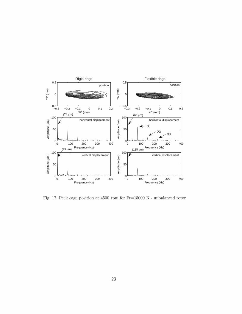
Their improved stability when a flexible ring is considered could be due to anincrease in the clearance between the cage and the inner guiding land, whichis hydrodynamically lubricated. When the rings are assumed to be rigid, theinfluence of the radial load is stronger, especially for the Peek cage sincethe first four harmonics of (X − Y ) appear for the vertical displacement inFig. 15. Similarly, for an unbalanced rotor, see Figs. 16 and 17, it is observedthat flexible rings have only a small effect on the cage position in comparisonto rigid rings, for both steel and Peek cage materials. However, it shouldbe underlined that the effect of the cage inertia is easy to identify: the firstfrequency harmonics (below X) observed in Fig. 13 are 2 or 3 times lower fora steel cage than those observed with a Peek cage (Fig. 17).
4 Conclusion
An unitary mathematical model is proposed to describe the dynamic behav-ior of a cylindrical roller bearing with flexible rings. Taking into account theflexibility of the rings leads to a smoother global response of the rotor-bearingassembly with less cage instabilities. Consequently, this assumption is a firstorder parameter for predicting the dynamic behavior of the system. It is alsofound that the ball pass harmonics are significantly modified when consideringthe ring flexibility. The first frequencies are more marked and the higher fre-quency is attenuated. Consequently, the inner ring trajectory loses one orderof complexity, even with an unbalanced rotor. An inter-shaft bearing operatingin a counter-rotating motion shows a larger number of frequency components:the unbalanced forces on both rings increase the non-linearity of the systemleading to many sub and super-harmonics. These sub- and super-harmonicsare found to be a linear combination of the two ring speeds. Finally, the inertiaof the cage material is found to play a role on the cage trajectory.
Acknowledgements
The authors wish to acknowledge N. Weinzapfel and F. Sadeghi of the Me-chanical Engineering Tribology Lab at the Purdue University for researching
17

support.
References
[1] Walter, C. T., 1971. “The Dynamics of Ball Bearings”. ASME Journal ofLubrification Technology, 93, pp. 1–10.
[2] Gupta, P. K., 1979. “Dynamics of Rolling-Element Bearings - Part I. CylindricalRoller Bearing Analysis”. ASME Journal of Lubrification Technology, 101,pp. 293–304.
[3] Gupta, P. K., 1984. Advanced Dynamics of Rolling Elements. Springer-Verlag,New-York.
[4] Gupta, P. K., 1979. “Dynamics of Rolling-Element Bearings - PartII. Cylindrical Roller Bearing Results”. ASME Journal of LubrificationTechnology, 101, pp. 305–311.
[5] Gupta, P. K., 1979. “Dynamics of Rolling-Element Bearings - Part III. Ball-Bearing Analysis”. ASME Journal of Lubrification Technology, 101, pp. 312–318.
[6] Gupta, P. K., 1979. “Dynamics of Rolling-Element Bearings - Part IV. Ball-Bearing Results”. ASME Journal of Lubrification Technology, 101, pp. 319–326.
[7] Meeks, C. R., and Tran, L., 1996. “Ball Bearing Dynamic Analysis UsingComputer Methods - Part I : Analysis”. ASME Journal of Tribology, 118,pp. 52–58.
[8] Meyer, L. D., Ahlgren, F. F., and Weichbrodt, B., 1980. “An Analytical Modelfor Ball Bearing Vibrations to Predict Vibration Response due to DistributedDefects”. Journal of Mechanical Design, 102, pp. 205–210.
[9] Su, Y. T., Lin, M. H., and Lee, M. S., 1993. “The Effects of Surface Irregularitieson Roller Bearing Vibrations”. Journal of Sound and Vibration, 165(3),pp. 455–466.
[10] Aini, R., Rahnejat, R., and Gohar, R., 1990. “A Five Degree of FreedomAnalysis of Vibrations in Precision Spindles”. Int. J. Mach. Tools Manufact.,30(1), pp. 1–18.
[11] Hendrikx, R. T. W. M., v. Nijen, G. C., and Dietl, P., 1998. “Vibrations inHousehold Appliances with Rolling Element Bearings”. Proc. ISMA 23 Noiseand Vibration Engineering, 3, pp. 1576–1544.
[12] Lee, Y. S., and Lee, C. W., 1999. “Modelling and vibration analysis ofmisaligned rotor-ball bearing systems”. Journal of Sound and Vibration, 224,July, pp. 17–32.
18

[13] Tiwari, M., Gupta, K., and Prakash, O., 2000. “Effect of radial internalclearance of a ball bearing on the dynamics of a balanced horizontal rotor”.Journal of Sound and Vibration, 238, pp. 723–756.
[14] Tiwari, M., Gupta, K., and Prakash, O., 2000. “Dynamic response of anunbalanced rotor supported on ball bearings”. Journal of Sound and Vibration,238, pp. 757–779.
[15] Harsha, S., Sandeep, K., and Prakash, R., 2003. “The effect of speed of balancedrotor on nonlinear vibrations associated with ball bearings”. InternationalJournal of Mechanical Science, 45, pp. 725–740.
[16] Changqing, B., and Qingyu, X., 2006. “Dynamic model of ball bearings withinternal clearance and waviness”. Journal of Sound and Vibration, 294, June,pp. 23–48.
[17] Jang, G., and Jeong, S.-W., 2004. “Vibration analysis of a rotating system dueto the effect of ball bearing waviness”. Journal of Sound and Vibration, 269,January, pp. 709–726.
[18] Palmgren, A., 1945. Ball and Roller Bearing Engineering, 1st ed. Philadelphia:SKF Industries Inc., Philadelphia.
[19] Cavallaro, G., Nelias, D., and Bon, F., 2005. “Analysis of High-Speed Inter-Shaft Cylindrical Roller Bearing with Flexible Rings”. Tribology Transactions,48(2), pp. 154–164.
[20] Hirotoshi, A., Yoshio, S., Yuka, M., and Takeshi, S., 1988. “Performance of ballbearings with silicon nitride ceramic balls in high speed spindles for machinetools”. Journal of Tribology, Transactions of the ASME, 110(4), pp. 693 – 698.
[21] Young, W. C., and Budynas, R. G., 2002. Roark’s Formulas for Stress andStrain, 7th edition ed. McGraw-Hill.
[22] Wensing, J. A., 1998. “On the dynamics of ball bearings”. PhD thesis,University of Twente, Enschede, The Netherlands, December.
[23] Ghaisas, N., Wassgren, C. R., and Sadeghi, F., 2004. “Cage Instabilities inCylindrical Roller Bearings”. ASME Journal of Tribology, 126, pp. 681–689.
19

−0.25 −0.2 −0.15 −0.1 −0.05 0−0.2
−0.1
0Rigid rings
XC (mm)
YC
(m
m)
−0.25 −0.2 −0.15 −0.1 −0.05 0−0.2
−0.1
0Flexible rings
XC (mm)
YC
(m
m)
0 100 200 300 4000
5
10
15
Frequency (Hz)
Am
plitu
de (
μm)
0 100 200 300 4000
5
10
15
Frequency (Hz)
Am
plitu
de (
μm)
0 100 200 300 4000
5
10
15
Frequency (Hz)
Am
plitu
de (
μm)
0 100 200 300 4000
5
10
15
Frequency (Hz)
Am
plitu
de (
μm)
positionposition
horizontal displacement horizontal displacement
vertical displacementvertical displacement
(157 μm)
X+Y
(111 μm) (123 μm)
(160 μm)
(X+Y)/2 (X+Y)/2
2Y
4Y
X−Y X−Y
Y
Fig. 14. Steel cage position at 4500 rpm for Fr=15000 N - balanced rotor
20

−0.25 −0.2 −0.15 −0.1 −0.05 0−0.2
−0.1
0Rigid rings
XC (mm)
YC
(m
m)
−0.25 −0.2 −0.15 −0.1 −0.05 0−0.2
−0.1
0Flexible rings
XC (mm)
YC
(m
m)
0 100 200 300 4000
2
4
6
8
Frequency (Hz)
Am
plitu
de (
μm)
0 100 200 300 4000
2
4
6
8
Frequency (Hz)
Am
plitu
de (
μm)
0 100 200 300 4000
2
4
6
8
Frequency (Hz)
Am
plitu
de (
μm)
0 100 200 300 4000
2
4
6
8
Frequency (Hz)
Am
plitu
de (
μm)
horizontal displacement
position position
horizontal displacement
vertical displacementvertical displacement
(X+Y)/2
4(X−Y)
X+Y
2(X+Y)
(161 μm) (151 μm)
(135 μm)(115 μm)
3(X−Y) 2(X−Y)
X−Y
Fig. 15. Peek cage position at 4500 rpm for Fr=15000 N - balanced rotor
21

−0.4 −0.2 0 0.2 0.4−0.5
0
0.5Rigid rings
XC (mm)
YC
(m
m)
−0.4 −0.2 0 0.2 0.4−0.5
0
0.5Flexible rings
XC (mm)
YC
(m
m)
0 100 200 300 4000
50
100
Frequency (Hz)
Am
plitu
de (
μm)
0 100 200 300 4000
50
100
Frequency (Hz)
Am
plitu
de (
μm)
0 100 200 300 4000
50
100
Frequency (Hz)
Am
plitu
de (
μm)
0 100 200 300 4000
50
100
Frequency (Hz)
Am
plitu
de (
μm)
position position
horizontal displacementhorizontal displacement
vertical displacement vertical displacement
(33 μm) (58 μm)
2X
X
Fig. 16. Steel cage position at 4500 rpm for Fr=15000 N - unbalanced rotor
22
−0.3 −0.2 −0.1 0 0.1 0.2−0.5
0
0.5Rigid rings
XC (mm)
YC
(m
m)
−0.3 −0.2 −0.1 0 0.1 0.2−0.5
0
0.5Flexible rings
XC (mm)
YC
(m
m)
0 100 200 300 4000
50
100
Frequency (Hz)
Am
plitu
de (
μm)
0 100 200 300 4000
50
100
Frequency (Hz)
Am
plitu
de (
μm)
0 100 200 300 4000
50
100
Frequency (Hz)
Am
plitu
de (
μm)
0 100 200 300 4000
50
100
Frequency (Hz)
Am
plitu
de (
μm)
horizontal displacement
position position
horizontal displacement
vertical displacementvertical displacement
X
2X 3X
(74 μm) (68 μm)
(115 μm)(99 μm)
Fig. 17. Peek cage position at 4500 rpm for Fr=15000 N - unbalanced rotor
23