CYLINDRICAL COPLANAR WAVEGUIDE0
22
Progress In Electromagnetics Research B, Vol. 3, 1–22, 2008 QUASI-STATIC MODELS BASED ON ARTIFICIAL NEURAL NETWORKS FOR CALCULATING THE CHARACTERISTIC PARAMETERS OF MULTILAYER CYLINDRICAL COPLANAR WAVEGUIDE AND STRIP LINE C. Yildiz and M. Turkmen Department of Electrical and Electronics Engineering Faculty of Engineering Erciyes University Kayseri 38039, Turkey Abstract—In this paper, two different neural models are proposed for calculating the quasi-static parameters of multilayer cylindrical coplanar waveguides and strip lines. These models were basically developed by training the artificial neural networks with the numerical results of quasi-static analysis. Neural models were trained with four different learning algorithms to obtain better performance and faster convergence with simpler structure. When the performances of neural models are compared with each other, the best test results are obtained from the multilayered perceptrons trained by the Levenberg- Marquardt algorithm. The results obtained from the neural models are in very good agreements with the theoretical results available in the literature. 1. INTRODUCTION Various coplanar waveguides (CPWs) and coplanar strip lines (CPSs) on planar substrates are widely used in microwave and millimeter wave integrated circuits due to their flexibility in the design of complex microwave circuitry requiring series and shunt connections. Recently, cylindrical CPW (CCPW) and cylindrical CPS (CCPS) with a single dielectric substrate or multilayer dielectric substrates have been proposed, which have the potential to be used in applications such as antennas, sensors, wireless communications, transition adapters, and baluns.
-
Upload
independent -
Category
Documents
-
view
0 -
download
0
Transcript of CYLINDRICAL COPLANAR WAVEGUIDE0
Progress In Electromagnetics Research B, Vol. 3, 1–22, 2008
QUASI-STATIC MODELS BASED ON ARTIFICIALNEURAL NETWORKS FOR CALCULATING THECHARACTERISTIC PARAMETERS OF MULTILAYERCYLINDRICAL COPLANAR WAVEGUIDE AND STRIPLINE
C. Yildiz and M. Turkmen
Department of Electrical and Electronics EngineeringFaculty of EngineeringErciyes UniversityKayseri 38039, Turkey
Abstract—In this paper, two different neural models are proposedfor calculating the quasi-static parameters of multilayer cylindricalcoplanar waveguides and strip lines. These models were basicallydeveloped by training the artificial neural networks with the numericalresults of quasi-static analysis. Neural models were trained withfour different learning algorithms to obtain better performance andfaster convergence with simpler structure. When the performances ofneural models are compared with each other, the best test results areobtained from the multilayered perceptrons trained by the Levenberg-Marquardt algorithm. The results obtained from the neural modelsare in very good agreements with the theoretical results available inthe literature.
1. INTRODUCTION
Various coplanar waveguides (CPWs) and coplanar strip lines (CPSs)on planar substrates are widely used in microwave and millimeterwave integrated circuits due to their flexibility in the design ofcomplex microwave circuitry requiring series and shunt connections.Recently, cylindrical CPW (CCPW) and cylindrical CPS (CCPS) witha single dielectric substrate or multilayer dielectric substrates havebeen proposed, which have the potential to be used in applications suchas antennas, sensors, wireless communications, transition adapters,and baluns.
2 Yildiz and Turkmen
So far, the various CCPWs and CCPSs have been analyzedby many researchers. CCPW with a single dielectric substrate hasbeen analyzed with the use of full-wave [1, 2] and quasi-static [3–5]methods. Multilayer CCPW has been analyzed by Alkan et al. [6]with the use of conformal mapping technique (CMT) which is themost often used quasi-static method. The quasi-static parameters ofCCPS having a single dielectric substrate [7, 8] and multilayer dielectricsubstrates [9, 10] have been determined with the use of CMT.
As mentioned above, CCPW and CCPS with a single dielectricsubstrate or multilayer dielectric substrates have been analyzed withthe use of quasi-static or full-wave methods. While full-wave methodsare the most accurate tools for obtaining the characteristic parametersof transmission lines and analytically extensive, quasi-static methodsare quite simple but do not threaten the dispersive nature of generictransmission lines. Consequently, the approximation of the quasi-staticmethods becomes worse as the transmission line becomes dispersive.
The aim of this paper is to present a new approximation basedon artificial neural networks (ANNs) to determine the quasi-staticparameters of multilayer CCPW and CCPS as an alternative method.As is well known, the quasi-static approximation is valid only at lowfrequencies. However, Bedair and Wolff [11] have shown that quasi-static approximation can be used in the design of coplanar monolithicmicrowave integrated circuits up to 40 GHz because of their very lowdispersion. For this reason the neural models to be proposed in thiswork can also be used to discuss the propagation characteristics ofmultilayer CCPW and CCPS, at least up to millimeter-wave frequencyrange.
Learning and generalization ability, fast real-time operation andease of implementation features have made ANNs popular in the lastdecade [12–14]. ANNs have been applied in many areas because ofthese features. Accurate and efficient microwave components, filtersand microstrip antennas have been analyzed and designed with theuse of ANNs [15–25]. In these applications, ANNs have more generalfunctional forms and are usually better than the classical techniques,and provide simplicity in real-time operation.
In this work, two different neural models are proposed forcalculating quasi-static parameters, the effective permittivity andcharacteristic impedance, of multilayer CCPW and CCPS. It shouldalso be emphasized that the presented neural models are not onlyvalid for multilayer CCPW and CCPS but also valid for CCPW andCCPS with a single dielectric layer. These neural models were trainedwith quasi-Newton (QN), Conjugate gradient with Flecther (CGF),Levenberg-Marquardt (LM) and Bayesian regulation (BR) learning
Progress In Electromagnetics Research B, Vol. 3, 2008 3
algorithms to obtain better performance and faster convergence withsimpler structure.
The performances of the neural models trained with differentlearning algorithms have been compared to each other. The inputsto the neural models are the three relative permittivities of thesubstrate materials and the three geometrical dimensions of multilayerCCPW and CCPS. The outputs of the neural models are the effectivepermittivity and characteristic impedance.
2. DETERMINATION OF THE QUASI-STATICPARAMETERS OF MULTILAYER CCPW AND CCPS
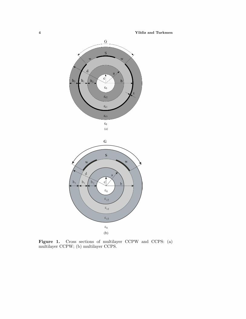
The cross-sections of multilayer CCPW and CCPS to be considered inthis work are depicted in Figs. 1(a) and 1(b), respectively. In thesefigures, S and w represent central strip and slot width for multilayerCCPW and represent slot width and strip width for multilayer CCPS.On the other hand, h1, h2 and h3 indicate the thickness of the dielectricmaterials with the relative permittivities εr1, εr2 and εr3 respectively.
In quasi-static analysis, all conductor materials are assumed to beperfectly conducting and the thickness of the conductor t is ignored.Using the quasi-static approximations, the effective permittivity εeff
and the characteristic impedance Z0 of the transmission lines are givenas;
εeff =C
C0(1)
Z0 =√
εeff
C · v0(2)
where v0 is the speed of light in free space, C is the total capacitance ofthe transmission line, C0 is the air capacitance of the line correspondingwith all dielectrics replaced by air. Therefore, one only has to find theair and total capacitances to obtain the quasi-static parameters of thetransmission lines.
The total capacitance of multilayer CCPW and CCPS can beexpressed as the sum of the air and partial capacitances as follow;
C = C0 + C1 + C2 + C3 (3)
Here C1, C2, and C3 are the partial capacitances of dielectric layerwith thickness h1 with relative permittivity εr1, the capacitance ofdielectric layer with thickness h2 with relative permittivity εr2, andthe capacitance of dielectric layer with thickness h3 with relativepermittivity εr3, respectively.
4 Yildiz and Turkmen
(a)
(b)
Figure 1. Cross sections of multilayer CCPW and CCPS: (a)multilayer CCPW; (b) multilayer CCPS.
Progress In Electromagnetics Research B, Vol. 3, 2008 5
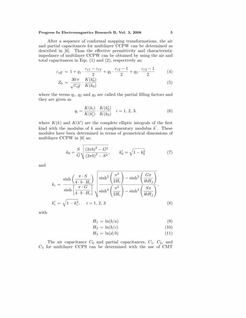
After a sequence of conformal mapping transformations, the airand partial capacitances for multilayer CCPW can be determined asdescribed in [6]. Than the effective permittivity and characteristicimpedance of multilayer CCPW can be obtained by using the air andtotal capacitances in Eqs. (1) and (2), respectively as;
εeff = 1 + q1 ·εr1 − εr2
2+ q2 ·
εr2 − 12
+ q3 ·εr3 − 1
2(4)
Z0 =30 π√
εeff· K(k′
0)K(k0)
(5)
where the terms q1, q2 and q3 are called the partial filling factors andthey are given as
qi =K(ki)K(k′
i)· K(k′
0)K(k0)
i = 1, 2, 3. (6)
where K(k) and K(k′) are the complete elliptic integrals of the firstkind with the modulus of k and complementary modulus k
′. These
modules have been determined in terms of geometrical dimensions ofmultilayer CCPW in [6] as;
k0 =S
G
√√√√(2πb)2 − G2
(2πb)2 − S2, k′
0 =√
1 − k20 (7)
and
ki =sinh
(π · S
4 · b · Hi
)
sinh[
π · G4 · b · Hi
]√√√√√√√√√
sinh2
(π2
2Hi
)− sinh2
(Gπ
4bHI
)
sinh2
(π2
2Hi
)− sinh2
(Sπ
4bHI
) ,
k′i =
√1 − k2
i , i = 1, 2, 3 (8)
with
H1 = ln(b/a) (9)H2 = ln(b/c) (10)H3 = ln(d/b) (11)
The air capacitance C0 and partial capacitances, C1, C2, andC3 for multilayer CCPS can be determined with the use of CMT
6 Yildiz and Turkmen
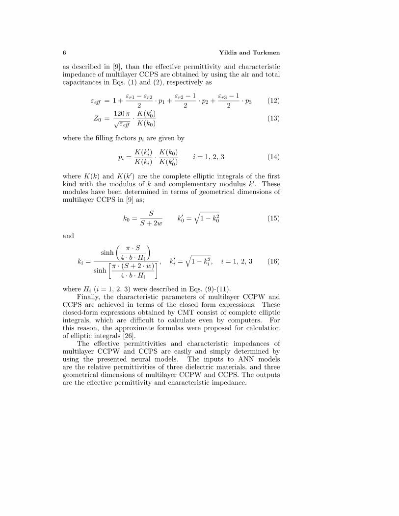
as described in [9], than the effective permittivity and characteristicimpedance of multilayer CCPS are obtained by using the air and totalcapacitances in Eqs. (1) and (2), respectively as
εeff = 1 +εr1 − εr2
2· p1 +
εr2 − 12
· p2 +εr3 − 1
2· p3 (12)
Z0 =120 π√
εeff· K(k′
0)K(k0)
(13)
where the filling factors pi are given by
pi =K(k′
i)K(ki)
· K(k0)K(k′
0)i = 1, 2, 3 (14)
where K(k) and K(k′) are the complete elliptic integrals of the firstkind with the modulus of k and complementary modulus k′. Thesemodules have been determined in terms of geometrical dimensions ofmultilayer CCPS in [9] as;
k0 =S
S + 2wk′
0 =√
1 − k20 (15)
and
ki =sinh
(π · S
4 · b · Hi
)
sinh[π · (S + 2 · w)
4 · b · Hi
] , k′i =
√1 − k2
i , i = 1, 2, 3 (16)
where Hi (i = 1, 2, 3) were described in Eqs. (9)-(11).Finally, the characteristic parameters of multilayer CCPW and
CCPS are achieved in terms of the closed form expressions. Theseclosed-form expressions obtained by CMT consist of complete ellipticintegrals, which are difficult to calculate even by computers. Forthis reason, the approximate formulas were proposed for calculationof elliptic integrals [26].
The effective permittivities and characteristic impedances ofmultilayer CCPW and CCPS are easily and simply determined byusing the presented neural models. The inputs to ANN modelsare the relative permittivities of three dielectric materials, and threegeometrical dimensions of multilayer CCPW and CCPS. The outputsare the effective permittivity and characteristic impedance.
Progress In Electromagnetics Research B, Vol. 3, 2008 7
3. ARTIFICIAL NEURAL NETWORKS (ANNS)
ANN learns relationships among sets of input-output data which arecharacteristic of the device under consideration. It is a very powerfulapproach for building complex and nonlinear relationship between a setof input and output data. ANNs are developed from neurophysiologyby morphologically and computationally mimicking human brains [12–14]. Although the precise operation details of ANNs are quite differentfrom those of human brains, they are similar in three aspects: theyconsist of a very large number of processing elements (the neurons),each neuron connects to a large number of other neurons, and thefunctionality of networks is determined by modifying the strengths ofconnections during a learning phase.
The power of neural computations comes from weight connectionin a network. Each neuron has weighted inputs, summation function,transfer function, and output. The behavior of a neural network isdetermined by the transfer functions of its neurons, by the learningrule, and model architecture. The weights are adjustable parametersand, in that sense, a neural network is a parameterized system. Theweighted sum of the inputs constitutes the activation of the neurons.The activation signal is passed through a transfer function to producethe output of a neuron. Transfer function introduces non-linearity tothe network. During training process, the inter-unit connections areoptimized until the error in predictions is minimized and the networkreaches the specified level of accuracy. Once the network is trained,new unseen input information is entered to the network to calculatethe output for test.
In the course of developing an ANN model, the architectureof the neural network and the learning algorithm are the mostimportant factors. ANNs have many structures and architectures [12–14]. The class of ANN and/or architecture selected for a particularmodel implementation depends on the problem to be solved.After several experiments using different architectures coupled withdifferent training algorithms, in this paper, the MLP neural networkarchitecture [12] was used to compute the quasi-TEM parameters ofmultilayer CCPW and CCPS.
3.1. Multilayered Perceptrons (MLPs)
The MLP is one of the most extensively used ANN architecture, dueto well-known general approximation capabilities, despite its limitedcomplexity. The MLP comprises an input layer, an output layer, anda number of hidden layers. Neurons in the input layer only act asbuffers for distributing the input signals xi to neurons in the hidden

8 Yildiz and Turkmen
layer. Each neuron j in the hidden layer sums up its input signals xi
after weighting them with the strengths of the respective connectionswji from the input layer and computes its output yj as a function f ofthe sum, namely;
yj = f(∑
wjixi
)(17)
f can be a simple threshold function, a sigmoidal or hyperbolic tangentfunction. The output of neurons in the output layer is computedsimilarly.
Training a network consists of adjusting weights of the network bya learning algorithm. The learning algorithm gives the change ∆wji(k)in the weight of a connection between neurons i and j at time k. Theweights are then updated according to the following formula;
wji(k + 1) = wji(k) + ∆wji(k + 1) (18)
MLPs can be trained using many different learning algorithms [12]. Inthis article, the following four learning algorithms used to train theMLPs were described briefly.
Levenberg-Marquardt (LM): This is a least-squares estima-tion method based on the maximum neighborhood idea [27, 28]. Itcombines the best features of the Gauss-Newton technique and thesteepest-descent method, but avoids many of their limitations. In par-ticular, it generally does not suffer from the problem of slow conver-gence.
Bayesian Regulation (BR): The BR algorithm updates theweight and bias values according to the LM optimization andminimizes a linear combination of squared errors and weights, and thendetermines the correct combination so as to produce a well generalizednetwork [29]. It takes place within the LM and requires more trainingand memory than the LM.
Conjugate Gradient of Fletcher-Powell (CGF): Thismethod updates weights and bias values according to the conjugategradient with Fletcher-Reeves [30, 31]. Each variable is adjusted tominimize the performance along the search direction. The line searchis used to locate the minimum point. The first search direction is thenegative of the gradient. In succeeding iterations the search directionis computed from the new gradient and the previous search direction.Fletcher-Reeves version of conjugate gradient uses the norm squareof previous gradient and the norm square of the current gradient tocalculate the weights and biases.
Quasi-Newton (QN): This is based on Newton’s method butdon’t require the calculation of second derivatives [32]. They updatean approximate Hessian matrix at an each iteration of the algorithm.

Progress In Electromagnetics Research B, Vol. 3, 2008 9
The update is computed as a function of the gradient. The line searchfunction is used to locate the minimum. The first search direction is thenegative of the gradient. In succeeding iterations the search directionis computed according to the gradient.
4. NEURAL MODELS FOR MULTILAYER CCPW ANDCCPS
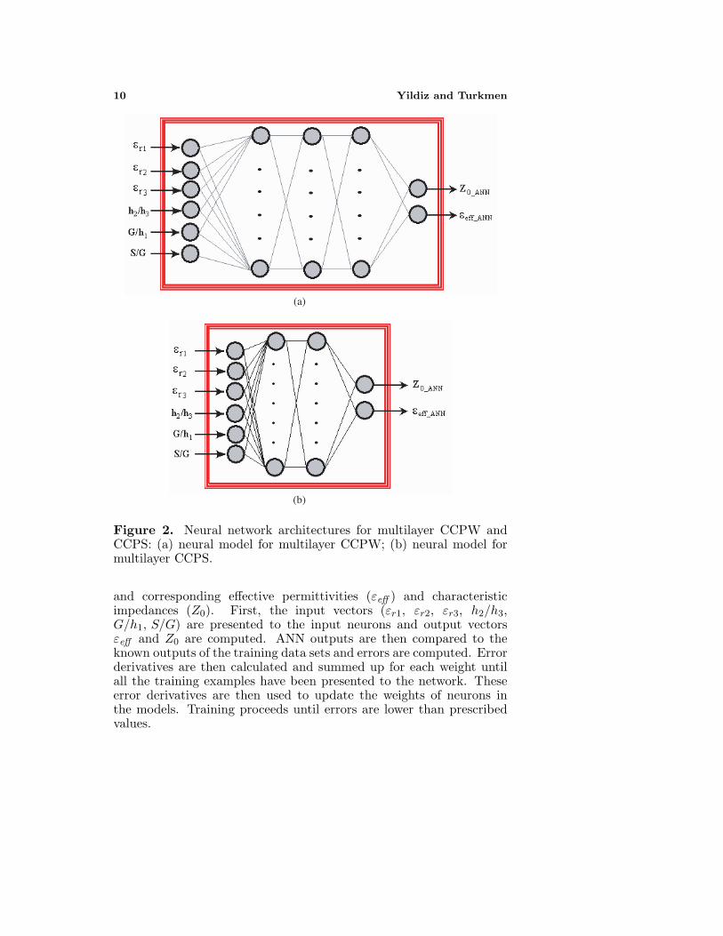
In this paper, two neural models are proposed for calculating thequasi-static parameters of multilayer CCPW and CCPS. For the neuralmodels, the inputs are the relative permittivities of substrate materialsεr1, εr2, εr3 and three geometrical dimensions h2/h3, G/h1, S/G,and the outputs are the effective permittivity (εeff ) and characteristicimpedance (Z0). Neural models used in calculating the effectivepermittivities and characteristic impedances of multilayer CCPW andCCPS are shown in Figs. 2(a) and 2(b), respectively.
ANN models are a kind of black box models, whose accuracydepends on the data presented to it during training process. A goodcollection of the training data, i.e., data which is well-distributed,sufficient, and accurately simulated, is the basic requirement to obtainan accurate model. For microwave applications, there are two types ofdata generators, namely measurement and simulation. The selectionof a data generator depends on the application and the availability ofthe data generator.
The training data sets were obtained from CMT introduced byAlkan et al. [6], and 1296 data sets were used to train the neuralmodel for multilayer CCPW. 576 data sets obtained from [3, 4, 6] wereused to test the neural model for multilayer CCPW. The training andtest data sets were obtained from CMT proposed by Gorur et al. [9]and 1008 data sets were used to train the neural model for multilayerCCPS. 448 data sets, which are completely different from training datasets, were used to test the neural model for multilayer CCPS. Theranges of the training data sets for both multilayer CCPW and CCPSare among 2 ≤ εr1 ≤ 14, 1 ≤ εr2 = εr3 ≤ 10, 0.1 ≤ S/G ≤ 0.9,1 ≤ G/h1 ≤ 4, 100 µm ≤ h1 ≤ 1500 µm, 200 µm ≤ h2 ≤ 1400 µm,100 µm ≤ h3 ≤ 1400 µm. The curvature ratio R = b/a was chosen forall structures as 0.8.
The aim of the training process is to minimize the trainingerror between the target outputs and the actual outputs of theANNs. Training the ANNs with the use of a learning algorithm tocalculate the effective permittivities and characteristic impedances ofmultilayer CCPW and CCPS involves presenting them sequentiallyand/or randomly with different sets (εr1, εr2, εr3, h2/h3, G/h1, S/G)
10 Yildiz and Turkmen
(a)
(b)
Figure 2. Neural network architectures for multilayer CCPW andCCPS: (a) neural model for multilayer CCPW; (b) neural model formultilayer CCPS.
and corresponding effective permittivities (εeff ) and characteristicimpedances (Z0). First, the input vectors (εr1, εr2, εr3, h2/h3,G/h1, S/G) are presented to the input neurons and output vectorsεeff and Z0 are computed. ANN outputs are then compared to theknown outputs of the training data sets and errors are computed. Errorderivatives are then calculated and summed up for each weight untilall the training examples have been presented to the network. Theseerror derivatives are then used to update the weights of neurons inthe models. Training proceeds until errors are lower than prescribedvalues.
Progress In Electromagnetics Research B, Vol. 3, 2008 11
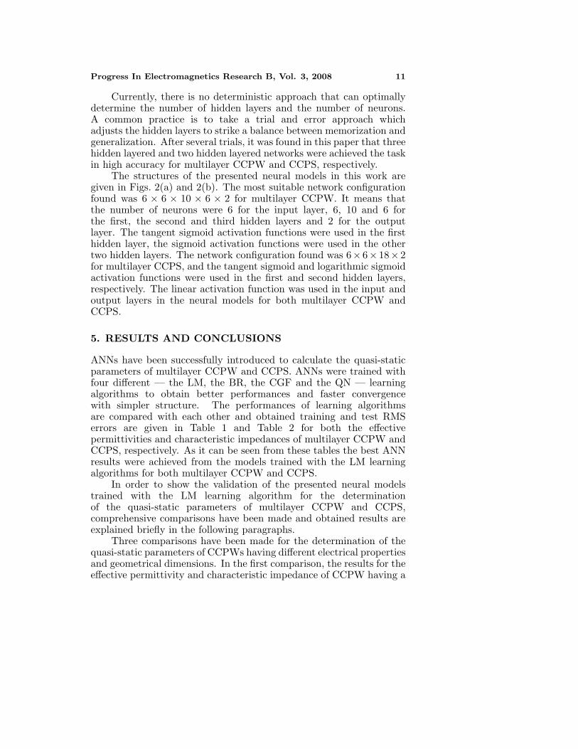
Currently, there is no deterministic approach that can optimallydetermine the number of hidden layers and the number of neurons.A common practice is to take a trial and error approach whichadjusts the hidden layers to strike a balance between memorization andgeneralization. After several trials, it was found in this paper that threehidden layered and two hidden layered networks were achieved the taskin high accuracy for multilayer CCPW and CCPS, respectively.
The structures of the presented neural models in this work aregiven in Figs. 2(a) and 2(b). The most suitable network configurationfound was 6 × 6 × 10 × 6 × 2 for multilayer CCPW. It means thatthe number of neurons were 6 for the input layer, 6, 10 and 6 forthe first, the second and third hidden layers and 2 for the outputlayer. The tangent sigmoid activation functions were used in the firsthidden layer, the sigmoid activation functions were used in the othertwo hidden layers. The network configuration found was 6× 6× 18× 2for multilayer CCPS, and the tangent sigmoid and logarithmic sigmoidactivation functions were used in the first and second hidden layers,respectively. The linear activation function was used in the input andoutput layers in the neural models for both multilayer CCPW andCCPS.
5. RESULTS AND CONCLUSIONS
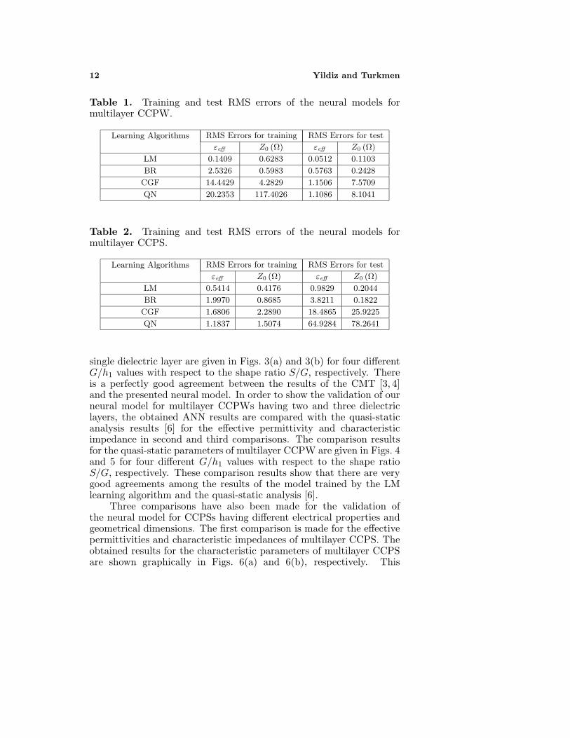
ANNs have been successfully introduced to calculate the quasi-staticparameters of multilayer CCPW and CCPS. ANNs were trained withfour different — the LM, the BR, the CGF and the QN — learningalgorithms to obtain better performances and faster convergencewith simpler structure. The performances of learning algorithmsare compared with each other and obtained training and test RMSerrors are given in Table 1 and Table 2 for both the effectivepermittivities and characteristic impedances of multilayer CCPW andCCPS, respectively. As it can be seen from these tables the best ANNresults were achieved from the models trained with the LM learningalgorithms for both multilayer CCPW and CCPS.
In order to show the validation of the presented neural modelstrained with the LM learning algorithm for the determinationof the quasi-static parameters of multilayer CCPW and CCPS,comprehensive comparisons have been made and obtained results areexplained briefly in the following paragraphs.
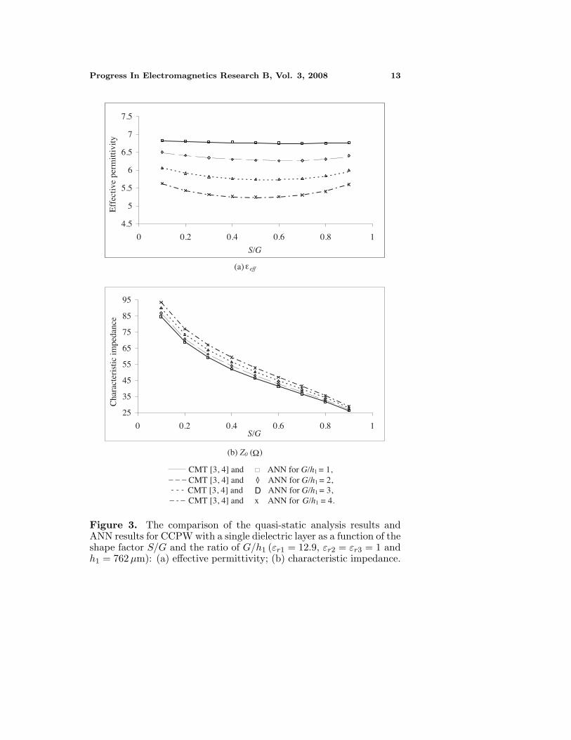
Three comparisons have been made for the determination of thequasi-static parameters of CCPWs having different electrical propertiesand geometrical dimensions. In the first comparison, the results for theeffective permittivity and characteristic impedance of CCPW having a
12 Yildiz and Turkmen
Table 1. Training and test RMS errors of the neural models formultilayer CCPW.
Learning Algorithms RMS Errors for training RMS Errors for test
εeff Z0 (Ω) εeff Z0 (Ω)
LM 0.1409 0.6283 0.0512 0.1103
BR 2.5326 0.5983 0.5763 0.2428
CGF 14.4429 4.2829 1.1506 7.5709
QN 20.2353 117.4026 1.1086 8.1041
Table 2. Training and test RMS errors of the neural models formultilayer CCPS.
Learning Algorithms RMS Errors for training RMS Errors for test
εeff Z0 (Ω) εeff Z0 (Ω)
LM 0.5414 0.4176 0.9829 0.2044
BR 1.9970 0.8685 3.8211 0.1822
CGF 1.6806 2.2890 18.4865 25.9225
QN 1.1837 1.5074 64.9284 78.2641
single dielectric layer are given in Figs. 3(a) and 3(b) for four differentG/h1 values with respect to the shape ratio S/G, respectively. Thereis a perfectly good agreement between the results of the CMT [3, 4]and the presented neural model. In order to show the validation of ourneural model for multilayer CCPWs having two and three dielectriclayers, the obtained ANN results are compared with the quasi-staticanalysis results [6] for the effective permittivity and characteristicimpedance in second and third comparisons. The comparison resultsfor the quasi-static parameters of multilayer CCPW are given in Figs. 4and 5 for four different G/h1 values with respect to the shape ratioS/G, respectively. These comparison results show that there are verygood agreements among the results of the model trained by the LMlearning algorithm and the quasi-static analysis [6].
Three comparisons have also been made for the validation ofthe neural model for CCPSs having different electrical properties andgeometrical dimensions. The first comparison is made for the effectivepermittivities and characteristic impedances of multilayer CCPS. Theobtained results for the characteristic parameters of multilayer CCPSare shown graphically in Figs. 6(a) and 6(b), respectively. This
Progress In Electromagnetics Research B, Vol. 3, 2008 13
4.5
5
5.5
6
6.5
7
7.5
0 0.2 0.4 0.6 0.8 1
S/G
Eff
ectiv
e pe
rmitt
ivity
.
(a) eff
25
35
45
55
65
75
85
95
0 0.2 0.4 0.6 0.8 1S/G
Cha
ract
eris
tic im
peda
nce
.
(b) Z0 ( )
ε
Ω
CMT [3, 4] and ANN for G/h1 = 1, CMT [3, 4] and ANN for G/h1 = 2,
CMT [3, 4] and ANN for G/h1 = 3, CMT [3, 4] and x ANN for G/h1 = 4.
<
<
D- - -
_ _ _
_ _-
Figure 3. The comparison of the quasi-static analysis results andANN results for CCPW with a single dielectric layer as a function of theshape factor S/G and the ratio of G/h1 (εr1 = 12.9, εr2 = εr3 = 1 andh1 = 762µm): (a) effective permittivity; (b) characteristic impedance.

14 Yildiz and Turkmen
6
7
8
9
10
11
12
0 0.2 0.4 0.6 0.8 1S/G
Eff
ectiv
e pe
rmitt
ivity
(a)
20
30
40
50
60
70
80
90
0 0.2 0.4 0.6 0.8 1S/G
Cha
ract
eris
tic im
peda
nce
(b) Z0 ( )
effε
Ω
CMT [6] and ANN for G/h1 = 1, CMT [6] and ANN for G/h1 = 2, CMT [6] and ANN for G/h1 = 3, CMT [6] and x ANN for G/h1 = 4.
<
<
D- - -
_ _ _
_ _-
Figure 4. The comparison of the quasi-static analysis results andANN results for CCPW with two dielectric layers as a function ofthe shape factor S/G and the ratio of G/h1 (εr1 = 12.9, εr2 = 1,εr3 = 10, h1 = 762µm and h3 = 635µm): (a) effective permittivity;(b) characteristic impedance.

Progress In Electromagnetics Research B, Vol. 3, 2008 15
6
7
8
9
10
11
12
0 0.2 0.4 0.6 0.8 1S/G
Eff
ectiv
e pe
rmitt
ivity
(a)
10
20
30
40
50
60
70
80
0 0.2 0.4 0.6 0.8 1S/G
Cha
ract
eris
tic
impe
danc
e
(b) Z0 ( ) Ω
CMT [6] and ANN for G/h1 = 1, CMT [6] and ANN for G/h1 = 2, CMT [6] and ANN for G/h1 = 3, CMT [6] and x ANN for G/h1 = 4.
<
<
D
effε
- - -
_ _ _
_ _-
Figure 5. The comparison of the quasi-static analysis results andANN results for CCPW with three dielectric layers as a function of theshape factor S/G and the ratio of G/h1 (εr1 = 12.9, εr2 = εr3 = 10,h1 = 762µm, and h2 = h3 = 500µm): (a) effective permittivity; (b)characteristic impedance.

16 Yildiz and Turkmen
89
1011121314151617
0 0.2 0.4 0.6 0.8 1S/G
Eff
ectiv
e pe
rmitt
ivity
(a)
40
60
80
100
120
140
0 0.2 0.4 0.6 0.8S/G
Cha
ract
eris
tic im
peda
nce
.
(b)
G/h1 = 1, CMT [9] ANN for G/h1 = 1, G/h1 = 2, CMT [9] ANN for G/h1 = 2, G/h1 = 3, CMT [9] ANN for G/h1 = 3, G/h1 = 4, CMT [9] x ANN for G/h1 = 4.
1
Z0 ( ) Ω
effε<
<
D- - -
_ _ _
_ _-
Figure 6. The comparison of the quasi-static analysis results andANN results for CCPS with three dielectric layers as a function of theshape ratio S/G for different values of G/h1 (εr1 = 12.9, εr2 = εr3 = 10,h1 = 762µm, and h2 = h3 = 500µm): (a) effective permittivity; (b)characteristic impedance.

Progress In Electromagnetics Research B, Vol. 3, 2008 17
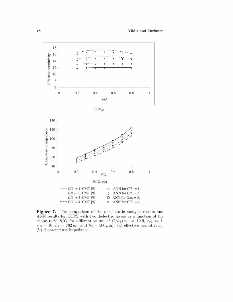
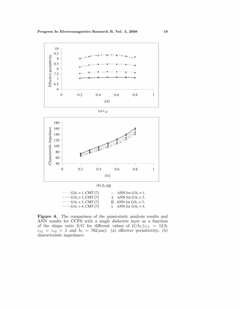
figure illustrates how the effective permittivity and characteristicimpedance of multilayer CCPS varies with the shape ratio S/G fordifferent values of G/h1. It is apparent from Fig. 6 that the resultsof ANN are in very good agreement with the results of CMT [9]for both effective permittivities and characteristic impedances. Thesecond comparison is made for the quasi-static parameters of CCPSwith two dielectric layers. The obtained results for the effectivepermittivities and characteristic impedances of multilayer CCPS areshown in Figs. 7(a) and 7(b), respectively. It can be seen from thisfigure there is again very good agreement between neural model resultstrained with LM and CMT [9] results for the quasi-static parameters ofCCPS with two dielectric layers. The last comparison is made for thecharacteristic parameters of CCPS with a single dielectric substrate(εr2 = εr3 = 1). The comparisons for the effective permittivityand characteristic impedance of this structure are shown in Figs. 8(a)and 8(b), respectively. This figure also show that there is very goodagreement between the neural results and CMT [7] results for botheffective permittivity and characteristic impedances.
All these comparison results obviously show that there are verygood agreements among the results of the neural models and the quasi-static analysis available in the literature for multilayer CCPW andCCPS. So the neural models presented in this work are very successfulfor the determination of the quasi-static parameters of CCPWs andCCPSs with a single dielectric and multilayer dielectrics. This verygood agreement also shows that neural models presented in this workare not only valid for multilayer CCPW and CCPS but also a singlelayered CCPW and CCPS. Moreover, it should be emphasized thatthe proposed neural model is much simpler and more useful for thedesigners than the other analyzing methods with a good accuracy.
Using the proposed neural model with a personal computer, onecan accurately calculate the characteristic parameters of multilayerCCPW and CCPS without processing any background knowledge.Even if training takes less than a few minutes, after training thecalculation time is less than a few microseconds in real-time calculation.Thus, the neural models are very fast after training. Finally, the neuralmodels presented in this study, achieves the determination of the quasi-static parameters of the multilayer cylindrical transmission lines withsimpler structure and high accuracy. It does not require complicatedmathematics and strong background knowledge so it can be very usefulfor the development of fast computer-aided design algorithms whichare capable of accurately predicting the characteristic parameters ofmultilayer CCPW and CCPS.
18 Yildiz and Turkmen
6
8
10
12
14
16
18
0 0.2 0.4 0.6 0.8 1
S/G
Eff
ectiv
e pe
rmitt
ivity
40
60
80
100
120
140
0 0.2 0.4 0.6 0.8S/G
Cha
ract
eris
tic im
peda
nce
.
1
(a) effε
(b)
G/h1 = 1, CMT [9] ANN for G/h1 = 1, G/h1 = 2, CMT [9] ANN for G/h1 = 2, G/h1 = 3, CMT [9] ANN for G/h1 = 3, G/h1 = 4, CMT [9] x ANN for G/h1 = 4.
Z0 ( ) Ω
<
<
D- - -
_ _ _
_ _-
Figure 7. The comparison of the quasi-static analysis results andANN results for CCPS with two dielectric layers as a function of theshape ratio S/G for different values of G/h1 (εr1 = 12.9, εr2 = 1,εr3 = 10, h1 = 762µm and h3 = 500µm): (a) effective permittivity;(b) characteristic impedance.
Progress In Electromagnetics Research B, Vol. 3, 2008 19
66.5
77.5
88.5
99.510
0 0.2 0.4 0.6 0.8 1
S/G
Eff
ectiv
e pe
rmitt
ivity
40
60
80
100
120
140
160
180
0 0.2 0.4 0.6 0.8 1
S/G
Cha
ract
eris
tic im
peda
nce
(a) effε
(b)
G/h1 = 1, CMT [7] ANN for G/h1 = 1, G/h1 = 2, CMT [7] ANN for G/h1 = 2, G/h1 = 3, CMT [7] ANN for G/h1 = 3, G/h1 = 4, CMT [7] x ANN for G/h1 = 4.
Z0 ( ) Ω
<
<
D- - -
_ _ _
_ _-
Figure 8. The comparison of the quasi-static analysis results andANN results for CCPS with a single dielectric layer as a functionof the shape ratio S/G for different values of G/h1 (εr1 = 12.9,εr2 = εr3 = 1 and h1 = 762µm): (a) effective permittivity; (b)characteristic impedance.
20 Yildiz and Turkmen
REFERENCES
1. Su, H. C. and K. L. Wong, “Dispersion characteristics ofcoplanar waveguide,” IEEE Transactions on Microwave Theoryand Techniques, Vol. 44, 2120–2122, 1996.
2. Dib, N., T. Weller, M. Scardeletti, and M. Imparato, “Analysisof cylindrical transmission lines with finite difference timedomain method,” IEEE Transactions on Microwave Theory andTechniques, Vol. 47, 509–512, 1999.
3. Su, H. C. and K. L. Wong, “Quasi-static solutions of cylindricalcoplanar waveguides,” Microwave Optical Technology Letters,Vol. 14, 347–351, 1997.
4. Dib, N. and A. Al-Zoubi, “Quasi-static analysis of asymmetriccylindrical coplanar waveguides with finite-extent ground,”International Jour. Electronics, Vol. 87, 185–198, 2000.
5. Karpuz, C., M. Duyar, and A. Gorur, “Analysis of cylindricalconductor-backed coplanar waveguides,” Microwave Optical Tech-nology Letters, Vol. 27, 144–146, 2000.
6. Alkan, M., A. Gorur, and C. Karpuz, “Quasi-static analysisof cylindrical coplanar waveguide with multilayer dielectrics,”International Jour. of RF and Microwave CAE, Vol. 8, 303–314,1998.
7. Karpuz, C., A. Gorur, and M. Alkan, “Quasistatic analysisof cylindrical coplanar strip lines,” Microwave and OpticalTechnology Letters, Vol. 17, 148–151, 1998.
8. Du, Z., K. Gong, J. S. Fu, Z. Feng, and B. Gao, “CAD models forasymmetrical, elliptical, cylindrical, and elliptical cone coplanarstrip lines,” IEEE Trans. Microwave Theory Tech., Vol. 48, 312–316, 2000.
9. Gorur, A., M. Duyar, and C. Karpuz, “Analytic formulas forcalculating the quasistatic parameters of a multilayer cylindricalcoplanar strip line,” Microwave and Optical Technology Letters,Vol. 22, 432–436, 1999.
10. Akan, V. and E. Yazgan, “Quasi-static solutions of multilayerelliptical, cylindrical coplanar striplines and multilayer coplanarstriplines with finite dielectric dimensions-asymmetrical case,”IEEE Trans. Microwave Theory Tech., Vol. 53, 3681–3686, 2005.
11. Bedair, S. S. and I. Wolff, “Fast and accurate analytic formulas forcalculating the parameters of a general broadside-coupled coplanarwaveguide for (M)MIC applications,” IEEE Trans. MicrowaveTheory Tech., Vol. 37, 843–850, 1989.
Progress In Electromagnetics Research B, Vol. 3, 2008 21
12. Haykin, S., Neural Networks: A Comprehensive Foundation,Macmillan College Publishing Comp., New York, USA, 1994.
13. Christodoulou, C. G. and M. Georgiopoulos, Application of NeuralNetworks in Electromagnetics, Artech House, MA, 2001.
14. Zhang, Q. J. and K. C. Gupta, Neural Networks for RF andMicrowave Design, Artech House, 2000.
15. Watson, P. M. and K. C. Gupta, “Design and optimization ofCPW circuits using EM-ANN models for CPW components,”IEEE Transaction Microwave Theory Techniques, Vol. 45, 2515–2523, 1997.
16. Devabhaktuni, V. K., M. C. E. Yagoub, Y. Fang, J. Xu,and Q. J. Zhang, “Neural networks for microwave modeling:model development issues and nonlinear modeling techniques,”International J. of RF and Microwave CAE, Vol. 11, 4–21, 2001.
17. Yildiz, C., S. Sagiroglu, and M. Turkmen, “Neural modelfor coplanar waveguide sandwiched between two dielectricsubstrates,” IEE Proceedings - Microwaves, Antennas andPropagation, Vol. 151, 7–12. 2004.
18. Guney, K., C. Yildiz, S. Kaya, and M. Turkmen, “Artificialneural networks for calculating the characteristic impedanceof airsuspended trapezoidal and rectangular-shaped microshieldlines,” Journal of Electromagnetic Wave and Applications, Vol. 20,1161–1174, 2006.
19. Jin, L. C., L. Ruan, and L. Y. Chun, “Design E-plane bandpassfilter based on EM-ANN model,” Journal of ElectromagneticWave and Applications, Vol. 20, 1061–1069, 2006.
20. Mohamed, M. D. A., E. A. Soliman, and M. A. El-Gamal, “Optimization and characterization of electromagneticallycoupled patch antennas using RBF neural networks,” Journal ofElectromagnetic Wave and Applications, Vol. 20, 1101–1114, 2006.
21. Yildiz, C., K. Guney, M. Turkmen, and S. Kaya, “Neural modelsfor coplanar stripline synthesis,” Progress in ElectromagneticsResearch, PIER 69, 127–144, 2007.
22. Ganatsos, T., K. Siakavara, and J. N. Sahalos, “Neural network-based design of EBG surfaces for effective polarization diversity ofwireless communications antenna systems,” PIERS Online, Vol. 3,1165–1169, 2007.
23. Siakavara, K., “Artificial neural network employment in thedesign of multilayered microstrip antenna with specified frequencyoperation,” PIERS Online, Vol. 3, 1278–1282, 2007.
22 Yildiz and Turkmen
24. Kabir, H., Y. Wang, M. Yu, and Q. Zhang, “Applications ofartificial neural network techniques in microwave filter modeling,optimization and design,” PIERS Online, Vol. 3, 1131–1135, 2007.
25. Cengiz, Y., F. Gunes, and U. Kilic, “Optimization of a microwaveamplifier using neural performance data sheets with a memeticalgorithm,” PIERS Proceedings, 227–231, Prague, Czech Repulic,August 27–30, 2007.
26. Hilberg, W., “From approximations to exact relations forcharacteristics impedances,” IEEE Trans. Microwave TheoryTech., Vol. 17, 259–265, 1969.
27. Levenberg, K., “A method for the solution of certain nonlinearproblems in least squares,” Quart. Appl. Math., Vol. 2, 164–168,1944.
28. Marquardt, D. W., “An algorithm for least-squares estimation ofnonlinear parameters,” J. Soc. Ind. Appl. Math., Vol. 11, 431–441,1963.
29. MacKay, D. J. C., “Bayesian interpolation,” Neural Computation,Vol. 4, 415–447, 1992.
30. Fletcher, R. and C. M. Reeves, “Function minimization byconjugate gradients,” Comput. J., Vol. 7, 149–154, 1964.
31. Scales, E., Introduction to Non-linear Optimization, Springer-Verlag, New York, 1985.
32. Gill, P. E., W. Murray, and M. H. Wright, Practical Optimization,Academic Press, New York, 1981.