Numerical simulation of conjugate heat and mass transfer process within cylindrical porous media...
12
Numerical simulation of conjugate heat and mass transfer process within cylindrical porous media with cylindrical dielectric cores in microwave freeze-drying Zhi Tao a, * , Hongwei Wu a,b,1 , Guohua Chen b,2 , Hongwu Deng a,1 a National Laboratory on Aero-engines, School of Jet Propulsion, Beijing University of Aeronautics and Astronautics, Beijing, China b Department of Chemical Engineering, The Hong Kong University of Science and Technology, Clear Water Bay, Kowloon, Hong Kong, China Received 26 June 2003; received in revised form 10 September 2004 Abstract This paper presents a numerical model for the process of microwave freeze-drying within a cylindrical porous media with cylindrical dielectric cores. The set of transient governing equations developed are solved numerically with variable time-step finite volume method. Analysis of numerical results may lead to following main conclusions for the new freeze-drying process: (1) Proper usage of cylindrical dielectric cores could dramatically reduce the drying time. (2) The loss factor e 00 of the cylindrical dielectric core is an important parameter influencing the drying behavior. (3) Two sublimation fronts do exist within the porous media due to the existence of inner dielectric cores. (4) The impact of cylindrical dielectric cores on drying could not be ignored even though the initial saturation is low (S 0 = 0.2). Ó 2004 Elsevier Ltd. All rights reserved. Keywords: Heat and mass transfer; Freeze-drying; Porous media; Cylindrical dielectric core; Loss factor 1. Introduction Freeze-drying (lyophilization) is used as a gentle dehydration method for heat sensitive materials espe- cially in food and pharmaceutical industries, usually for the purpose of preservation. It is well known for its ability to sustain the high quality of products (colour, shape, aroma, texture, biological activity, etc.) than any other drying methods due to its low processing temper- ature and no oxygen involved in the process. Other advantages of freeze-drying include its protection against chemical decomposition, ease of rehydration, etc. However, freeze-drying is an expensive dehydration process because of low drying rates, high capital and en- ergy costs generated by refrigeration and vacuum sys- tems, and relatively long drying time required [1–5]. As a consequence, the use of freeze-drying on the industrial scale is restricted to high added-value products. Freeze- drying by microwave heating, however, has proven to overcome those disadvantages as it has the characteristic 0017-9310/$ - see front matter Ó 2004 Elsevier Ltd. All rights reserved. doi:10.1016/j.ijheatmasstransfer.2004.09.008 * Corresponding author. Tel.: +86 10 8231 7443; fax: +86 10 8231 7432. E-mail addresses: [email protected] (Z. Tao), hongwei_ [email protected] (H. Wu), [email protected] (G. Chen), [email protected] (H. Deng). 1 Tel.: +86 10 8231 4545. 2 Tel.: +852 2358 7138; fax: +852 2358 0054. International Journal of Heat and Mass Transfer 48 (2005) 561–572 www.elsevier.com/locate/ijhmt
-
Upload
independent -
Category
Documents
-
view
0 -
download
0
Transcript of Numerical simulation of conjugate heat and mass transfer process within cylindrical porous media...
International Journal of Heat and Mass Transfer 48 (2005) 561–572
www.elsevier.com/locate/ijhmt
Numerical simulation of conjugate heat and mass transferprocess within cylindrical porous media with cylindrical
dielectric cores in microwave freeze-drying
Zhi Tao a,*, Hongwei Wu a,b,1, Guohua Chen b,2, Hongwu Deng a,1
a National Laboratory on Aero-engines, School of Jet Propulsion, Beijing University of Aeronautics and Astronautics, Beijing, Chinab Department of Chemical Engineering, The Hong Kong University of Science and Technology, Clear Water Bay, Kowloon,
Hong Kong, China
Received 26 June 2003; received in revised form 10 September 2004
Abstract
This paper presents a numerical model for the process of microwave freeze-drying within a cylindrical porous media
with cylindrical dielectric cores. The set of transient governing equations developed are solved numerically with variable
time-step finite volume method. Analysis of numerical results may lead to following main conclusions for the new
freeze-drying process: (1) Proper usage of cylindrical dielectric cores could dramatically reduce the drying time. (2)
The loss factor e00 of the cylindrical dielectric core is an important parameter influencing the drying behavior. (3)
Two sublimation fronts do exist within the porous media due to the existence of inner dielectric cores. (4) The impact
of cylindrical dielectric cores on drying could not be ignored even though the initial saturation is low (S0 = 0.2).
� 2004 Elsevier Ltd. All rights reserved.
Keywords: Heat and mass transfer; Freeze-drying; Porous media; Cylindrical dielectric core; Loss factor
1. Introduction
Freeze-drying (lyophilization) is used as a gentle
dehydration method for heat sensitive materials espe-
cially in food and pharmaceutical industries, usually
for the purpose of preservation. It is well known for
0017-9310/$ - see front matter � 2004 Elsevier Ltd. All rights reserv
doi:10.1016/j.ijheatmasstransfer.2004.09.008
* Corresponding author. Tel.: +86 10 8231 7443; fax: +86 10
8231 7432.
E-mail addresses: [email protected] (Z. Tao), hongwei_
[email protected] (H. Wu), [email protected] (G. Chen),
[email protected] (H. Deng).1 Tel.: +86 10 8231 4545.2 Tel.: +852 2358 7138; fax: +852 2358 0054.
its ability to sustain the high quality of products (colour,
shape, aroma, texture, biological activity, etc.) than any
other drying methods due to its low processing temper-
ature and no oxygen involved in the process. Other
advantages of freeze-drying include its protection
against chemical decomposition, ease of rehydration,
etc. However, freeze-drying is an expensive dehydration
process because of low drying rates, high capital and en-
ergy costs generated by refrigeration and vacuum sys-
tems, and relatively long drying time required [1–5]. As
a consequence, the use of freeze-drying on the industrial
scale is restricted to high added-value products. Freeze-
drying by microwave heating, however, has proven to
overcome those disadvantages as it has the characteristic
ed.
Nomenclature
a coefficient
A area, m2
b source term
c specific heat, J/(kg �C)D diffusivity, m2/s
E electric field strength, V/m
f frequency, MHz
DH sublimation latent heat of ice, J/kg
I vapor source intensity, kg/(m3s)
J mass flux, kg/(m2s)
Jvs mass flux of vapor in icy region, kg/(m2s)
KD permeability, m2
Kr relative permeability,
m mass, kg
P pressure, Pa
PR vacuum pressure, Pa
q density of microwave power absorbed,
J/(sm3)
r polar coordinate direction
R water vapor gas constant, m2/(s2K)
Rd radius of cylindrical dielectric core, m
RP initial radius of porous material, m
S saturation (ice volume)/(void volume)
t temperature, �CT temperature, K
TR vacuum temperature, K
u velocity, m/s
usat moisture content, kg/(m3)
V volume, m3
Greek symbols
a heat transfer coefficient, W/(m2�C)e porosity
e 0 permittivity, F/m
e00 loss factor
/ generalized variable
k thermal conductivity, W/(m �C)l viscosity, kg/(ms)
q density, kg/m3
s time, s
n small value
Subscripts
0 initial
1 first sublimation front
2 second sublimation front
a with cylindrical dielectric core
b without cylindrical dielectric core
d cylindrical dielectric core
e effective
f sublimation front
F final time
i ice
I initial time
nb neighbor
p current control volume
s solid body
v vapor
w wall of porous material
562 Z. Tao et al. / International Journal of Heat and Mass Transfer 48 (2005) 561–572
of heating up materials volumetrically. Experiments and
numerical predictions all showed that the microwave
freeze-drying appears to be one of the most promising
techniques to accelerate the rate of dehydration and en-
hance overall quality [6–14].
Copson, in 1962, firstly modeled the microwave
freeze-drying process with pseudo steady- state assump-
tion that had been used in conventional freeze-drying
modeling. Much efforts have been devoted afterwards
to this area by many researchers [7,15,10,11,16,17]. Ma
and Peltre [18] presented a transient one-dimensional
model, which was the first transient analysis of micro-
wave freeze-drying. A more general analysis was under-
taken by Ma and Peltre [10,11] to improve the accuracy
of the Copson model, and was later extended to be two-
dimensional by Ang et al. [12] to take into account of the
material anisotropy. Chen et al. [19] studied volatile
retention in microwave freeze dried model foods. Wang
and Shi [20–24] developed a model which took into ac-
count the sublimation or condensation by vapor trans-
port in the unsaturated frozen region, and saturation
change was considered. Further research on microwave
freeze-drying focused on optimization of combined radi-
ant and microwave aided freeze-drying [17] and solid
entrainment [25,26].
Although ordinary microwave freeze-drying could
dramatically accelerate the drying process, it has much
room to be enhanced further by adding dielectric cores
to the porous materials to be dried. The dielectric core
is functioning an another heat source because the dielec-
tric core has to be properly selected high loss factor than
ice so that the microwave energy will be mainly taken by
the core during drying. In this way, the porous material
will be heated from both inside and outside at the same
time, which could remarkably increase the drying pro-
cess. Adding dielectric cores is, therefore, a novel, inter-
esting, and also industrially relevant drying technique.
Wu et al. [27] presented a double sublimation front
model within spherical porous media with dielectric
cores in microwave freeze-drying. By now, there is not
a single report on using dielectric materials within cylin-
drical porous media in microwave freeze-drying.
In the present study, a numerical simulation is car-
ried out to investigate the microwave freeze-drying with
Z. Tao et al. / International Journal of Heat and Mass Transfer 48 (2005) 561–572 563
cylindrical dielectric cores. A transient model is devel-
oped and it has three sets of governing equations for
the dried, the icy and the dielectric regions, respectively.
Since these regions are coupled together by energy and
mass transfer, the corresponding three sets of equations
have to be solved simultaneously. This complex conju-
gate problem is tackled with variable time-step finite
volume method. The main objective of this study is to
see the feasibility of microwave freeze-drying with cylin-
drical dielectric cores and any new phenomena
pertinent.
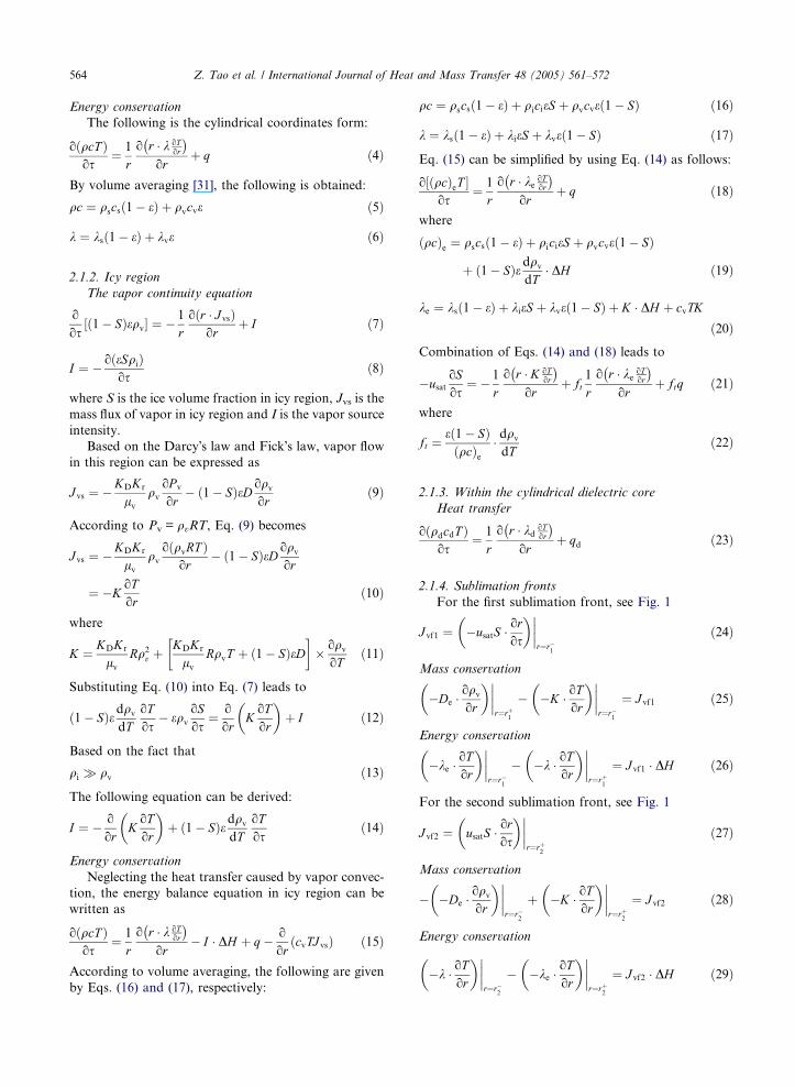
2. Mathematical modeling
The simplified one-dimensional physical configura-
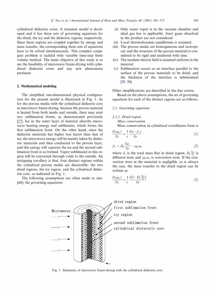
tion for the present model is illustrated in Fig. 1. As
for the porous media with the cylindrical dielectric core
in microwave freeze-drying, because the porous material
is heated from both inside and outside, there may exist
two sublimation fronts, as demonstrated previously
[27]. Ice in the outer layer of material absorbs micro-
wave heating energy and sublimates, which forms the
first sublimation front. On the other hand, since the
dielectric materials has higher loss factor than that of
ice, the microwave energy will be mainly taken by dielec-
tric materials and then conducted to the porous layer,
and this energy will vaporize the ice and the second sub-
limation front is so formed. Vapor sublimated in this re-
gion will be convected through voids to the outside. An
intriguing corollary is that, four distinct regions within
the cylindrical porous media are discernible: the two
dried regions, the icy region, and the cylindrical dielec-
tric core, as indicated in Fig. 1.
The following assumptions are often made to sim-
plify the governing equations:
Fig. 1. Schematic of microwave freeze-dryi
(i) Only water vapor is in the vacuum chamber and
ideal gas law is applicable. Inert gases dissolved
in the product are not considered.
(ii) Local thermodynamic equilibrium is assumed.
(iii) The porous media are homogeneous and isotropi-
cal, and the structure of the porous material is con-
sidered to be rigid and unaltered with time.
(iv) The incident electric field is assumed uniform in the
material.
(v) Sublimation occurs at an interface parallel to the
surface of the porous materials to be dried, and
the thickness of the interface is infinitesimal
[28–30].
Other simplifications are described in the due course.
Based on the above assumptions, the set of governing
equations for each of the distinct regions are as follows.
2.1. Governing equations
2.1.1. Dried region
Mass conservation
Mass conservation in cylindrical coordinates form is
oðeqvÞos
¼ 1
roðr � J vÞ
orð1Þ
J v ¼ De
oqv
or� eqvuv ð2Þ
where Jv is the total mass flux in dried region, Deoqvor is
diffusion term and eqvuv is convection term. If the con-
vection term in the material is negligible, as is always
the case, the mass transfer in the dried region can be
written as
oðeqvÞos
¼ 1
ro r � De
oqvor
� �or
ð3Þ
ng with the cylindrical dielectric core.
564 Z. Tao et al. / International Journal of Heat and Mass Transfer 48 (2005) 561–572
Energy conservation
The following is the cylindrical coordinates form:
oðqcT Þos
¼ 1
ro r � k oT
or
� �or
þ q ð4Þ
By volume averaging [31], the following is obtained:
qc ¼ qscsð1� eÞ þ qvcve ð5Þ
k ¼ ksð1� eÞ þ kve ð6Þ
2.1.2. Icy region
The vapor continuity equation
o
os½ð1� SÞeqv ¼ � 1
roðr � J vsÞ
orþ I ð7Þ
I ¼ � oðeSqiÞos
ð8Þ
where S is the ice volume fraction in icy region, Jvs is the
mass flux of vapor in icy region and I is the vapor source
intensity.
Based on the Darcy�s law and Fick�s law, vapor flowin this region can be expressed as
J vs ¼ �KDKr
lv
qv
oP v
or� ð1� SÞeD oqv
orð9Þ
According to Pv = qvRT, Eq. (9) becomes
J vs ¼ �KDKr
lv
qv
oðqvRT Þor
� ð1� SÞeD oqv
or
¼ �KoTor
ð10Þ
where
K ¼ KDKr
lv
Rq2v þ
KDKr
lv
RqvT þ ð1� SÞeD� �
oqv
oTð11Þ
Substituting Eq. (10) into Eq. (7) leads to
ð1� SÞedqv
dToTos
� eqv
oSos
¼ o
orKoTor
� �þ I ð12Þ
Based on the fact that
qi � qv ð13Þ
The following equation can be derived:
I ¼ � o
orKoTor
� �þ ð1� SÞedqv
dToTos
ð14Þ
Energy conservation
Neglecting the heat transfer caused by vapor convec-
tion, the energy balance equation in icy region can be
written as
oðqcT Þos
¼ 1
ro r � k oT
or
� �or
� I � DH þ q� o
orðcvTJ vsÞ ð15Þ
According to volume averaging, the following are given
by Eqs. (16) and (17), respectively:
qc ¼ qscsð1� eÞ þ qicieS þ qvcveð1� SÞ ð16Þ
k ¼ ksð1� eÞ þ kieS þ kveð1� SÞ ð17Þ
Eq. (15) can be simplified by using Eq. (14) as follows:
o½ðqcÞeT os
¼ 1
r
o r � keoTor
� �or
þ q ð18Þ
where
ðqcÞe ¼ qscsð1� eÞ þ qicieS þ qvcveð1� SÞ
þ ð1� SÞedqv
dT� DH ð19Þ
ke ¼ ksð1� eÞ þ kieS þ kveð1� SÞ þ K � DH þ cvTK
ð20ÞCombination of Eqs. (14) and (18) leads to
�usatoSos
¼ � 1
ro r � K oT
or
� �or
þ ft1
ro r � ke
oTor
� �or
þ ftq ð21Þ
where
ft ¼eð1� SÞðqcÞe
� dqv
dTð22Þ
2.1.3. Within the cylindrical dielectric core
Heat transfer
oðqdcdT Þos
¼ 1
r
o r � kdoTor
� �or
þ qd ð23Þ
2.1.4. Sublimation fronts
For the first sublimation front, see Fig. 1
J vf1 ¼ �usatS � oros
�� ����r¼r�
1
ð24Þ
Mass conservation
�De �oqv
or
� �����r¼rþ
1
� �K � oTor
� �����r¼r�
1
¼ J vf1 ð25Þ
Energy conservation
�ke �oTor
� �����r¼r�
1
� �k � oTor
� �����r¼rþ
1
¼ J vf1 � DH ð26Þ
For the second sublimation front, see Fig. 1
J vf2 ¼ usatS � oros
�� ����r¼rþ
2
ð27Þ
Mass conservation
� �De �oqv
or
� �����r¼r�
2
þ �K � oTor
� �����r¼rþ
2
¼ J vf2 ð28Þ
Energy conservation
�k � oTor
� �����r¼r�
2
� �ke �oTor
�� ����r¼rþ
2
¼ J vf2 � DH ð29Þ
Z. Tao et al. / International Journal of Heat and Mass Transfer 48 (2005) 561–572 565
2.1.5. Boundary conditions
Due to symmetry of the material, the boundary con-
ditions at the center and surface are
�kd �oTor
����r¼0
¼ 0 ð30Þ
�k � oTor
� �����r¼Rp
¼ aðT jr¼Rp� TRÞ ð31Þ
qvjr¼Rp¼ PR
RT r¼RP
ð32Þ
oqv
or
����r¼0
¼ 0 ð33Þ
oqv
or
����r¼rd
¼ 0 ð34Þ
2.1.6. Initial conditions
T js¼0 ¼ T 0 ð35Þ
Rjs¼0 ¼ Rp ð36Þ
Sjs¼0 ¼ S0 ð37Þ
The microwave power dissipation per unit volume with-
in the material is related to the electric field strength E
and the dielectric properties of the material by the fol-
lowing equation q = 2pfe 0e00E2.
2.1.7. General energy balance
Q1 þ Q2 þ Q3 ¼ Q4 þ Q5 þ Q6 þ Q7 þ Q8 ð38Þ
where
Q1 ¼R sF
sIqiV i ds the quantity of microwave power that
is absorbed by the ice during the whole drying
Q2 = qdVdsF the quantity of microwave power that is
absorbed by the cylindrical dielectric core dur-
ing the whole drying
Q3 = qsVssF the quantity of microwave power that is
absorbed by the material during the whole
drying
Q4 ¼R sF
sIcimiðT i � T 0Þds the energy needed when ice
converted into vapor at sublimation tempera-
ture during drying
Q5 ¼R sF
sIcdmdðT d � T 0Þds the energy needed for the
cylindrical dielectric core from the start to the
end of the drying process
Q6 ¼R sF
sIcsmsðT s � T 0Þds the energy needed for the
material from beginning to the end of the dry-
ing process
Q7 = mi ÆDH the energy needed for the sublimation of
ice during the whole drying
Q8 ¼R sF
sIaAwðTw � TRÞds the transmitted energy flux
at the surface of the material?
3. Physical properties
This research aims to investigate the phenomena of
microwave freeze-drying of cylindrical porous media
with cylindrical dielectric cores, and to further verify
the applicability of the previously studied double subli-
mation front model developed for spherical porous med-
ia with spherical dielectric cores [27]. It is, therefore,
reasonable not to limit to any specific materials, a set
of commonly accepted physical properties are more
favorable to reveal general inherent natures. The se-
lected physical properties are listed in Table 1 and they
are all selected from previously published references.
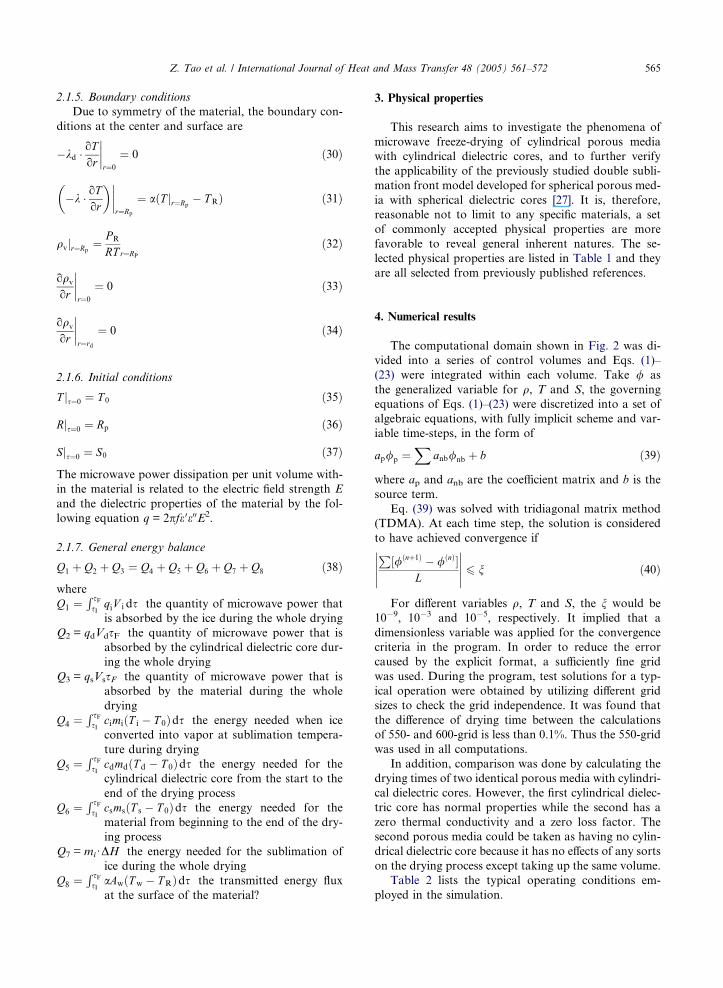
4. Numerical results
The computational domain shown in Fig. 2 was di-
vided into a series of control volumes and Eqs. (1)–
(23) were integrated within each volume. Take / as
the generalized variable for q, T and S, the governing
equations of Eqs. (1)–(23) were discretized into a set of
algebraic equations, with fully implicit scheme and var-
iable time-steps, in the form of
ap/p ¼X
anb/nb þ b ð39Þ
where ap and anb are the coefficient matrix and b is the
source term.
Eq. (39) was solved with tridiagonal matrix method
(TDMA). At each time step, the solution is considered
to have achieved convergence if
P½/ðnþ1Þ � /ðnÞ
L
���������� 6 n ð40Þ
For different variables q, T and S, the n would be
10�9, 10�3 and 10�5, respectively. It implied that a
dimensionless variable was applied for the convergence
criteria in the program. In order to reduce the error
caused by the explicit format, a sufficiently fine grid
was used. During the program, test solutions for a typ-
ical operation were obtained by utilizing different grid
sizes to check the grid independence. It was found that
the difference of drying time between the calculations
of 550- and 600-grid is less than 0.1%. Thus the 550-grid
was used in all computations.
In addition, comparison was done by calculating the
drying times of two identical porous media with cylindri-
cal dielectric cores. However, the first cylindrical dielec-
tric core has normal properties while the second has a
zero thermal conductivity and a zero loss factor. The
second porous media could be taken as having no cylin-
drical dielectric core because it has no effects of any sorts
on the drying process except taking up the same volume.
Table 2 lists the typical operating conditions em-
ployed in the simulation.
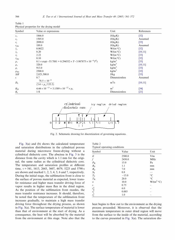
Table 1
Physical properties for the drying model
Symbol Value or expressions Unit References
cv 1866.0 J/(kgK) [32]
cs 1505.0 J/(kgK) Assumed
ci 2090.0 J/(kgK) [33]
cdie 189.0 J/(kgK) Assumed
kv 0.0022 W/(m�C) [32]
ks 0.20 W/(m�C) [10,11]
ki 2.22 W/(m�C) [33]
kdie 0.10 W/(m�C) [32]
qv 0.1 · exp(�53.7881 + 0.294552 · T�3.987875 · 10�4T2) kg/m3 [33]
qs 320.0 kg/m3 [10,11]
qi 913.0 kg/m3 [33]
qdie 2500.0 kg/m3 [32]
DH 2,821,500.0 J/kg [33]
e 0.7 Dimensionless Assumed
De
78:5 10�4
ð3:4þ pv=133:3Þm2/s [10,11]
KD 4.44 · 10�13 + 3.1589 · 10�12 · pv m2 [34]
Kr 1-S Dimensionless [21]
Fig. 2. Schematic drawing for discretization of governing equations.
Table 2
Typical operating conditions
Symbol Value Unit
E 2500.0 V/m
f 2450.0 MHz
PR 15.0 Pa
Rd 1.1 mm
Rp 7.0 mm
S0 0.8 —
T0 �15.0 �CTR 20.0 �Ca 10.0 W/(m2 �C)e 0.75 –
e00d 6.0 –
e00i 0.003 –
e00s 1.0 –
566 Z. Tao et al. / International Journal of Heat and Mass Transfer 48 (2005) 561–572
Fig. 3(a) and (b) shows the calculated temperature
and saturation distributions in the cylindrical porous
material during microwave freeze-drying without a
cylindrical dielectric core. The abscissa in Fig. 3 is the
distance from the cavity which is 1.1 mm for the origi-
nal, the same radius as the cylindrical dielectric core.
The temperature and saturation profiles at different
time, s = 541, 1613, 2643, 3607, 4479, 5225 and 5790 s
are shown and marked 1, 2, 3, 4, 5, 6 and 7, respectively.
During the initial stage, the sublimation front is close to
the surface of porous material as expected, lower trans-
fer resistance and higher mass transfer driving force of
vapor results in higher mass flux in the dried region.
As the position of the sublimation front recedes, the
mass transfer resistance increases. It should, therefore,
be noted that the temperature of the sublimation front
increases gradually, to maintain a high mass transfer
driving force throughout the drying process, as shown
in Fig. 3(a). The surface temperature of material is lower
than that of environment at the start of drying. As a
consequence, the heat will be absorbed by the material
from the environment at this stage. Note also that the
heat begins to flow out to the environment as the drying
process proceeded. Moreover, it is observed that the
maximum temperature in outer dried region will move
from the surface to the inside of the material, according
to the curves presented in Fig. 3(a). The saturation dis-
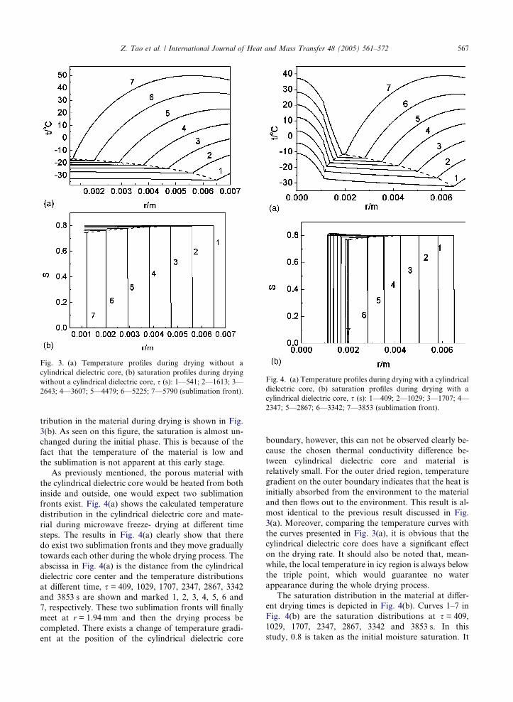
Fig. 3. (a) Temperature profiles during drying without a
cylindrical dielectric core, (b) saturation profiles during drying
without a cylindrical dielectric core, s (s): 1—541; 2—1613; 3—
2643; 4—3607; 5—4479; 6—5225; 7—5790 (sublimation front).
Fig. 4. (a) Temperature profiles during drying with a cylindrical
dielectric core, (b) saturation profiles during drying with a
cylindrical dielectric core, s (s): 1—409; 2—1029; 3—1707; 4—
2347; 5—2867; 6—3342; 7—3853 (sublimation front).
Z. Tao et al. / International Journal of Heat and Mass Transfer 48 (2005) 561–572 567
tribution in the material during drying is shown in Fig.
3(b). As seen on this figure, the saturation is almost un-
changed during the initial phase. This is because of the
fact that the temperature of the material is low and
the sublimation is not apparent at this early stage.
As previously mentioned, the porous material with
the cylindrical dielectric core would be heated from both
inside and outside, one would expect two sublimation
fronts exist. Fig. 4(a) shows the calculated temperature
distribution in the cylindrical dielectric core and mate-
rial during microwave freeze- drying at different time
steps. The results in Fig. 4(a) clearly show that there
do exist two sublimation fronts and they move gradually
towards each other during the whole drying process. The
abscissa in Fig. 4(a) is the distance from the cylindrical
dielectric core center and the temperature distributions
at different time, s = 409, 1029, 1707, 2347, 2867, 3342
and 3853 s are shown and marked 1, 2, 3, 4, 5, 6 and
7, respectively. These two sublimation fronts will finally
meet at r = 1.94 mm and then the drying process be
completed. There exists a change of temperature gradi-
ent at the position of the cylindrical dielectric core
boundary, however, this can not be observed clearly be-
cause the chosen thermal conductivity difference be-
tween cylindrical dielectric core and material is
relatively small. For the outer dried region, temperature
gradient on the outer boundary indicates that the heat is
initially absorbed from the environment to the material
and then flows out to the environment. This result is al-
most identical to the previous result discussed in Fig.
3(a). Moreover, comparing the temperature curves with
the curves presented in Fig. 3(a), it is obvious that the
cylindrical dielectric core does have a significant effect
on the drying rate. It should also be noted that, mean-
while, the local temperature in icy region is always below
the triple point, which would guarantee no water
appearance during the whole drying process.
The saturation distribution in the material at differ-
ent drying times is depicted in Fig. 4(b). Curves 1–7 in
Fig. 4(b) are the saturation distributions at s = 409,
1029, 1707, 2347, 2867, 3342 and 3853 s. In this
study, 0.8 is taken as the initial moisture saturation. It

Fig. 6. The variation of location of sublimation fronts with
drying time.
568 Z. Tao et al. / International Journal of Heat and Mass Transfer 48 (2005) 561–572
is interesting to note that local saturation near the sec-
ond sublimation front could be higher than initial satu-
ration during early stage of drying. This is because of the
fact that vapor sublimated due to cylindrical dielectric
core heating could not fully flow out of the icy region
and is partly recondensed to be ice, which caused the in-
crease of local saturation. This interesting phenomenon
is clearly indicated by Fig. 4(b). This phenomenon will,
however, disappear gradually with the decrease in satu-
ration. The saturation distribution in icy region is flat. It
can also be seen that the drying process is completed at
the location of r = 1.94 mm, which consists with that of
Fig. 4(a).
Fig. 5 shows the distributions of vapor density within
porous media at different times during drying with a
cylindrical dielectric core. The vapor density decreases
monotonously from the cylindrical dielectric core
boundary to the surface of the column during the entire
drying process. Though the gradients are much larger in
dried region, the vapor transfer exists in icy region as ex-
pressed in Eq. (9). Fig. 5 indicates that the vapor will be
removed from icy region. As a result, the ice in icy re-
gion will sublimate and the saturation in this region will
decrease as shown in Fig. 4(b). The vapor density curves
in both dried region will also meet at the end of drying,
as shown in curve 7.
The results presented in Fig. 6 show the variation of
location of sublimation front with drying time. Compar-
ison was done by calculating the position of sublimation
front with cylindrical dielectric core and without, curves
2 and 1, respectively. The results shown in Fig. 6 corre-
spond to those in Figs. 3 and 4. It is obvious that the
drying curve for having cylindrical dielectric core case
shows a dramatically increased drying rate. The drying
curve plotted in Fig. 6 show that the cylindrical dielec-
tric core case caused roughly half an hour reduction in
drying time. This is explained by the fact that in the
Fig. 5. Profiles of vapor density during drying with a cylindrical
dielectric core, s (s): 1—409; 2—1029; 3—1707; 4—2347; 5—
2867; 6—3342; 7—3853 (sublimation front).
cylindrical dielectric core case, the material will be
heated from both inside and outside. Thus, the temper-
ature rise of the material will be accelerated and the heat
provided for sublimation should also be increased
accordingly. As a result, this situation results in a much
higher drying rate. Therefore, the second sublimation
front plays an important role in reducing drying time.
In Fig. 7, temperature curves at the moment of dry-
ing process termination are plotted for different initial
saturations with cylindrical dielectric core. Four initial
saturation conditions are used in the simulation i.e.
S = 0.2, 0.4, 0.6 and 0.8. The abscissa in Fig. 7 is the dis-
tance from the cylindrical dielectric core center, and the
initial radius of cylindrical porous material is kept con-
stant as Rp = 7.0 mm. The temperature distributions at
the end of drying, s = 865, 1826, 2826, and 3853 s are
shown and marked 1, 2, 3, and 4, respectively. In each
case, it is shown from the simulation results (Fig. 7) that
Fig. 7. Temperature curves at the moment of drying process
termination for different initial saturations.
Z. Tao et al. / International Journal of Heat and Mass Transfer 48 (2005) 561–572 569
the shapes of the temperature distributions are similar at
the end of drying, the main differences are due to differ-
ent initial saturations. It is important to note that the
end point of the second sublimation front is much closer
to the outer layer of the material with the decrease of ini-
tial saturation. This is the result of higher temperature
gradient and much more enhancive vapor transfer capa-
bility near the boundary of the cylindrical dielectric core,
therefore, the moving velocity of the second sublimation
front would be faster.
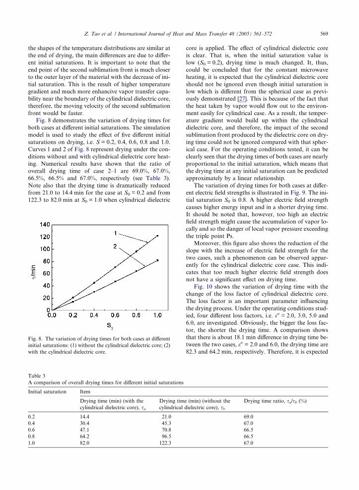
Fig. 8 demonstrates the variation of drying times for
both cases at different initial saturations. The simulation
model is used to study the effect of five different initial
saturations on drying, i.e. S = 0.2, 0.4, 0.6, 0.8 and 1.0.
Curves 1 and 2 of Fig. 8 represent drying under the con-
ditions without and with cylindrical dielectric core heat-
ing. Numerical results have shown that the ratio of
overall drying time of case 2–1 are 69.0%, 67.0%,
66.5%, 66.5% and 67.0%, respectively (see Table 3).
Note also that the drying time is dramatically reduced
from 21.0 to 14.4 min for the case at S0 = 0.2 and from
122.3 to 82.0 min at S0 = 1.0 when cylindrical dielectric
Fig. 8. The variation of drying times for both cases at different
initial saturations: (1) without the cylindrical dielectric core; (2)
with the cylindrical dielectric core.
Table 3
A comparison of overall drying times for different initial saturations
Initial saturation Item
Drying time (min) (with the
cylindrical dielectric core), sa
Drying tim
cylindrical
0.2 14.4 21.0
0.4 30.4 45.3
0.6 47.1 70.8
0.8 64.2 96.5
1.0 82.0 122.3
core is applied. The effect of cylindrical dielectric core
is clear. That is, when the initial saturation value is
low (S0 = 0.2), drying time is much changed. It, thus,
could be concluded that for the constant microwave
heating, it is expected that the cylindrical dielectric core
should not be ignored even though initial saturation is
low which is different from the spherical case as previ-
ously demonstrated [27]. This is because of the fact that
the heat taken by vapor would flow out to the environ-
ment easily for cylindrical case. As a result, the temper-
ature gradient would build up within the cylindrical
dielectric core, and therefore, the impact of the second
sublimation front produced by the dielectric core on dry-
ing time could not be ignored compared with that spher-
ical case. For the operating conditions tested, it can be
clearly seen that the drying times of both cases are nearly
proportional to the initial saturation, which means that
the drying time at any initial saturation can be predicted
approximately by a linear relationship.
The variation of drying times for both cases at differ-
ent electric field strengths is illustrated in Fig. 9. The ini-
tial saturation S0 is 0.8. A higher electric field strength
causes higher energy input and in a shorter drying time.
It should be noted that, however, too high an electric
field strength might cause the accumulation of vapor lo-
cally and so the danger of local vapor pressure exceeding
the triple point Ps.
Moreover, this figure also shows the reduction of the
slope with the increase of electric field strength for the
two cases, such a phenomenon can be observed appar-
ently for the cylindrical dielectric core case. This indi-
cates that too much higher electric field strength does
not have a significant effect on drying time.
Fig. 10 shows the variation of drying time with the
change of the loss factor of cylindrical dielectric core.
The loss factor is an important parameter influencing
the drying process. Under the operating conditions stud-
ied, four different loss factors, i.e. e00 = 2.0, 3.0, 5.0 and
6.0, are investigated. Obviously, the bigger the loss fac-
tor, the shorter the drying time. A comparison shows
that there is about 18.1 min difference in drying time be-
tween the two cases, e00 = 2.0 and 6.0, the drying time are
82.3 and 64.2 min, respectively. Therefore, it is expected
e (min) (without the
dielectric core), sb
Drying time ratio, sa/sb (%)
69.0
67.0
66.5
66.5
67.0
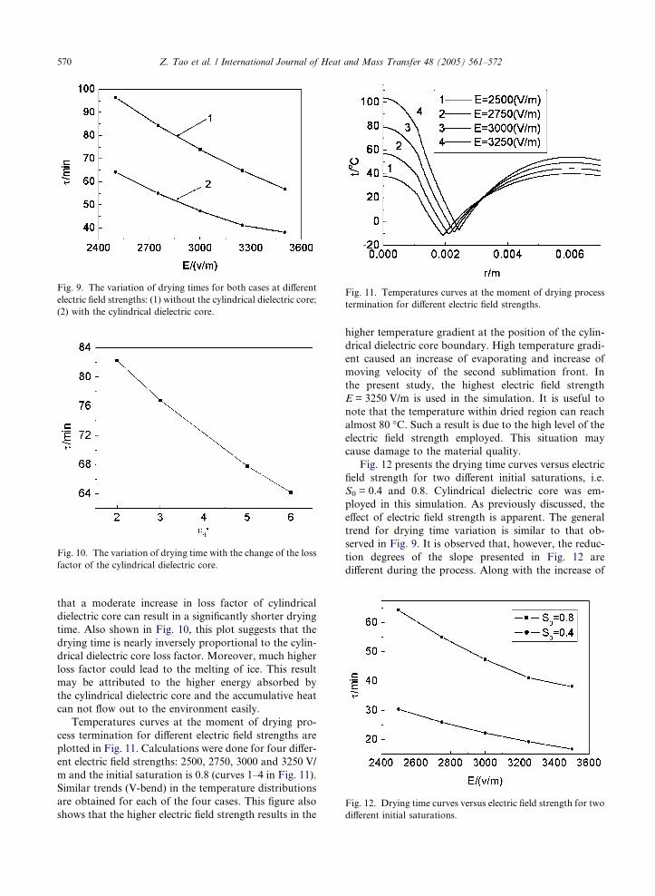
Fig. 9. The variation of drying times for both cases at different
electric field strengths: (1) without the cylindrical dielectric core;
(2) with the cylindrical dielectric core.
Fig. 10. The variation of drying time with the change of the loss
factor of the cylindrical dielectric core.
Fig. 11. Temperatures curves at the moment of drying process
termination for different electric field strengths.
Fig. 12. Drying time curves versus electric field strength for two
different initial saturations.
570 Z. Tao et al. / International Journal of Heat and Mass Transfer 48 (2005) 561–572
that a moderate increase in loss factor of cylindrical
dielectric core can result in a significantly shorter drying
time. Also shown in Fig. 10, this plot suggests that the
drying time is nearly inversely proportional to the cylin-
drical dielectric core loss factor. Moreover, much higher
loss factor could lead to the melting of ice. This result
may be attributed to the higher energy absorbed by
the cylindrical dielectric core and the accumulative heat
can not flow out to the environment easily.
Temperatures curves at the moment of drying pro-
cess termination for different electric field strengths are
plotted in Fig. 11. Calculations were done for four differ-
ent electric field strengths: 2500, 2750, 3000 and 3250 V/
m and the initial saturation is 0.8 (curves 1–4 in Fig. 11).
Similar trends (V-bend) in the temperature distributions
are obtained for each of the four cases. This figure also
shows that the higher electric field strength results in the
higher temperature gradient at the position of the cylin-
drical dielectric core boundary. High temperature gradi-
ent caused an increase of evaporating and increase of
moving velocity of the second sublimation front. In
the present study, the highest electric field strength
E = 3250 V/m is used in the simulation. It is useful to
note that the temperature within dried region can reach
almost 80 �C. Such a result is due to the high level of the
electric field strength employed. This situation may
cause damage to the material quality.
Fig. 12 presents the drying time curves versus electric
field strength for two different initial saturations, i.e.
S0 = 0.4 and 0.8. Cylindrical dielectric core was em-
ployed in this simulation. As previously discussed, the
effect of electric field strength is apparent. The general
trend for drying time variation is similar to that ob-
served in Fig. 9. It is observed that, however, the reduc-
tion degrees of the slope presented in Fig. 12 are
different during the process. Along with the increase of
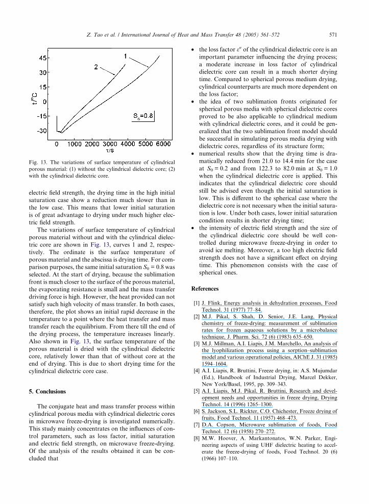
Fig. 13. The variations of surface temperature of cylindrical
porous material: (1) without the cylindrical dielectric core; (2)
with the cylindrical dielectric core.
Z. Tao et al. / International Journal of Heat and Mass Transfer 48 (2005) 561–572 571
electric field strength, the drying time in the high initial
saturation case show a reduction much slower than in
the low case. This means that lower initial saturation
is of great advantage to drying under much higher elec-
tric field strength.
The variations of surface temperature of cylindrical
porous material without and with the cylindrical dielec-
tric core are shown in Fig. 13, curves 1 and 2, respec-
tively. The ordinate is the surface temperature of
porous material and the abscissa is drying time. For com-
parison purposes, the same initial saturation S0 = 0.8 was
selected. At the start of drying, because the sublimation
front is much closer to the surface of the porous material,
the evaporating resistance is small and the mass transfer
driving force is high. However, the heat provided can not
satisfy such high velocity of mass transfer. In both cases,
therefore, the plot shows an initial rapid decrease in the
temperature to a point where the heat transfer and mass
transfer reach the equilibrium. From there till the end of
the drying process, the temperature increases linearly.
Also shown in Fig. 13, the surface temperature of the
porous material is dried with the cylindrical dielectric
core, relatively lower than that of without core at the
end of drying. This is due to short drying time for the
cylindrical dielectric core case.
5. Conclusions
The conjugate heat and mass transfer process within
cylindrical porous media with cylindrical dielectric cores
in microwave freeze-drying is investigated numerically.
This study mainly concentrates on the influences of con-
trol parameters, such as loss factor, initial saturation
and electric field strength, on microwave freeze-drying.
Of the analysis of the results obtained it can be con-
cluded that
• the loss factor e00 of the cylindrical dielectric core is animportant parameter influencing the drying process;
a moderate increase in loss factor of cylindrical
dielectric core can result in a much shorter drying
time. Compared to spherical porous medium drying,
cylindrical counterparts are much more dependent on
the loss factor;
• the idea of two sublimation fronts originated for
spherical porous media with spherical dielectric cores
proved to be also applicable to cylindrical medium
with cylindrical dielectric cores, and it could be gen-
eralized that the two sublimation front model should
be successful in simulating porous media drying with
dielectric cores, regardless of its structure form;
• numerical results show that the drying time is dra-
matically reduced from 21.0 to 14.4 min for the case
at S0 = 0.2 and from 122.3 to 82.0 min at S0 = 1.0
when the cylindrical dielectric core is applied. This
indicates that the cylindrical dielectric core should
still be advised even though the initial saturation is
low. This is different to the spherical case where the
dielectric core is not necessary when the initial satura-
tion is low. Under both cases, lower initial saturation
condition results in shorter drying time;
• the intensity of electric field strength and the size of
the cylindrical dielectric core should be well con-
trolled during microwave freeze-drying in order to
avoid ice melting. Moreover, a too high electric field
strength does not have a significant effect on drying
time. This phenomenon consists with the case of
spherical ones.
References
[1] J. Flink, Energy analysis in dehydration processes, Food
Technol. 31 (1977) 77–84.
[2] M.J. Pikal, S. Shah, D. Senior, J.E. Lang, Physical
chemistry of freeze-drying: measurement of sublimation
rates for frozen aqueous solutions by a microbalance
technique, J. Pharm. Sci. 72 (6) (1983) 635–650.
[3] M.J. Millman, A.I. Liapis, J.M. Marchello, An analysis of
the lyophilization process using a sorption–sublimation
model and various operational policies, AIChE J. 31 (1985)
1594–1604.
[4] A.I. Liapis, R. Bruttini, Freeze drying, in: A.S. Mujumdar
(Ed.), Handbook of Industrial Drying, Marcel Dekker,
New York/Basel, 1995, pp. 309–343.
[5] A.I. Liapis, M.J. Pikal, R. Bruttini, Research and devel-
opment needs and opportunities in freeze drying, Drying
Technol. 14 (1996) 1265–1300.
[6] S. Jackson, S.L. Rickter, C.O. Chichester, Freeze drying of
fruits, Food Technol. 11 (1957) 468–473.
[7] D.A. Copson, Microwave sublimation of foods, Food
Technol. 12 (6) (1958) 270–272.
[8] M.W. Hoover, A. Markantonatos, W.N. Parker, Engi-
neering aspects of using UHF dielectric heating to accel-
erate the freeze-drying of foods, Food Technol. 20 (6)
(1966) 107–110.
572 Z. Tao et al. / International Journal of Heat and Mass Transfer 48 (2005) 561–572
[9] M.W. Hoover, A. Markantonatos, W.N. Parker, UHF
dielectric heating in experimental acceleration of freeze-
drying of foods, Food Technol. 20 (6) (1966) 103–107.
[10] Y.H. Ma, P. Peltre, Freeze dehydration by microwave
energy: Part I. Theoretical investigation, AIChE J. 21 (2)
(1975) 335–344.
[11] Y.H. Ma, P. Peltre, Freeze dehydration by microwave
energy: Part II. Experimental investigation, AIChE J. 21
(2) (1975) 344–350.
[12] T.K. Ang, J.D. Ford, D.C.T. Pei, Microwave freeze-drying
of food: a theoretical investigation, Int. J. Heat Mass
Transfer 20 (5) (1977) 517–526.
[13] T.K. Ang, D.C.T. Pei, J.D. Ford, Microwave freeze-drying
of food: an experimental investigation, Chem. Eng. Sci. 32
(1977) 1477–1489.
[14] J. Sochanske, J. Goyette, T. Bose, C. Akyel, R. Bosisio,
Freeze dehydration of foamed milk by microwave, Drying
Technol. 8 (1990) 1017–1037.
[15] J.W. Gould, E.M. Kenyon, Gas discharge and electric field
strength in microwave freeze-drying, J. Microwave Power 6
(2) (1971) 151–167.
[16] T.K. Ang, J.D. Ford, D.C.T. Pei, Optimal modes of
operation for microwave freeze drying of food, J. Food Sci.
43 (1978) 648–649.
[17] T.N. Chang, Y.H. Ma, Application of optimal control
strategy to hybrid microwave and radiant freeze drying
system, in: Drying 85, Hemisphere, Washington, DC, 1985,
pp. 249–253.
[18] Y.H. Ma, P. Peltre, Mathematical simulation of a freeze
drying process using microwave energy, in: Food Preser-
vationAIChE Symposium Series, vol. 69, 1973, pp. 47–54.
[19] S.D. Chen, R.Y. Ofoli, E.P. Scott, J. Asmussen, Volatile
retention in microwave freeze-dried model foods, J. Food
Sci. 58 (1993) 1157–1161.
[20] M.H. Shi, Z.H. Wang, A sublimation–condensation theory
for the microwave freeze drying of unsaturated porous
media, J. Southeast Univ. (China) 25 (4) (1995) 92–98 (in
Chinese).
[21] Z.H. Wang, M.H. Shi, Analysis of heat and mass transfer
for microwave freeze drying of unsaturated porous media,
J. Chem. Ind. Eng. (China) 47 (2) (1996) 131–136 (in
Chinese).
[22] Z.H. Wang, M.H. Shi, Effects of heating methods on
vacuum freeze drying, Drying Technol. 15 (5) (1997) 1475–
1498.
[23] Z.H. Wang, M.H. Shi, Numerical study on sublimation–
condensation phenomena during microwave freeze drying,
Chem. Eng. Sci. 53 (18) (1998) 3189–3197.
[24] Z.H. Wang, M.H. Shi, Microwave freeze drying charac-
teristics of beef, Drying Technol. 17 (3) (1999) 433–447.
[25] H.B. Arsem, Y.H. Ma, Aerosol formation during the
microwave freeze dehydration of beef, Biotechnol. Progr. 1
(1985) 104–110.
[26] H.B. Arsem, Y.H. Ma, Simulation of a combined micro-
wave and radiant freeze dryer, Drying Technol. 8 (1990)
993–1016.
[27] H.W. Wu, Z. Tao, G.H. Chen, H.W. Deng, Conjugate
heat and mass transfer process within porous media with
dielectric cores in microwave freeze drying, Chem. Eng.
Sci. 59 (14) (2004) 2921–2928.
[28] C.J. King, Freeze-Drying of Foods, CRC Press, Cleveland,
OH, 1971.
[29] S.A. Goldblith, L. Rey, W.W. Rothmayr, Freeze Drying
and Advanced Food Technology, Academic Press, New
York, 1975.
[30] J.D. Mellor, Fundamentals of Freeze-Drying, Academic
Press, New York, 1978.
[31] S. Whitaker, A theory of drying in porous media, Adv.
Heat Transfer 13 (1977) 119–203.
[32] S.M. Yang, Heat Transfer, second ed., Beijing, China, 1987.
[33] H.R. Perry, D. Green, J.O. Maloney, Perry�s Chemical
Engineering Handbook, sixth ed., McGraw-Hill, New
York, 1992.
[34] J.C. Harper, Transport properties of gases in porous media
at reduced pressures with reference to freeze-drying,
AIChE J. 8 (3) (1962) 298–302.