
Nokia Eseries Deployment Guide version 1.1 - Cisco Community
76
C o p y r i g h t 20 0 7 C is c o S y s t e m s , I n c . T h e p a r t s o f t h is d o c u m e n t r e f e r r in g t o N o k ia d e v ic e s o r N o k ia S o f t w a r e are c o p y r i g h t 20 0 7 N o k ia C o r p o r a tio n . A ll r ig h ts reserved. P a g e 1 o f 76 Disclaimer THE SPECIFICATIONS AND INFORMATION REGARDING THE PRODUCTS IN THIS DOCUMENT ARE SUBJECT TO CHANGE WITHOUT NOTICE. AL L STATEMENTS, INFORMATION, AND RECOMMENDATIONS IN THIS DOCUMENT ARE PROVIDED “AS-IS” W IT H OU T AN Y W ARRAN T Y W H AT SOEVER. C ISC O SPEC IF IC AL L Y AN D EX PRESSL Y DISC L AIM S AN Y W ARRAN T IES OR C ON DIT ION S, ST AT U T ORY OR OT H ERW ISE, IN C L U DIN G W IT H OU T L IM IT AT ION T H E IM PL IED W ARRAN T IES OF M ERC H AN T AB IL IT Y , F IT N ESS F OR A PART IC U L AR PU RPOSE AN D N ON IN F RIN G EM EN T . USERS MUST TAK E FUL L RESPONSIBIL ITY FOR THEIR APPL ICATION OF ANY PRODUCTS. THE SOFTWARE L ICENSE AND L IMITED WARRANTY FOR THE ACCOMPANY ING PRODUCT ARE SET FORTH IN THE INFORMATION PACK ET THAT SHIPPED WITH THE PRODUCT AND ARE INCORPORATED HEREIN BY THIS REFERENCE. IF Y OU ARE UNABL E TO L OCATE THE SOFTWARE L ICENSE OR L IMITED WARRANTY , CONTACT Y OUR CISCO REPRESENTATIV E FOR A COPY . Th e Ci s c o im p le m e n ta tio n o f TCP h e a d e r c o m p r e s s io n is a n a d a p ta tio n o f a p r o g r a m d e v e lo p e d b y th e Un iv e r s ity o f Ca lif o r n ia , Be r k e le y ( UCB) a s part o f UCB’ s p u b lic d o m a in v e r s io n o f th e UNIX o p e r a tin g s y s te m . All r ig h ts r e s e r v e d . Co p y r ig h t © 1 9 8 1 , Re g e n ts o f th e Un iv e r s ity o f California. NOTWITHSTANDING ANY OTHER WARRANTY HEREIN, AL L PRODUCTS, DOCUMENT FIL ES AND SOFTWARE OF CISCO’ S SUPPL IERS ARE PROV IDED “ AS IS” W IT H OU T AN Y W ARRAN T Y W H AT SOEVER. CISCO AND CISCO’ S SUPPL IERS DISCL AIM AL L WARRANTIES, EX PRESSED OR IMPL IED, INCL UDING, WITHOUT L IMITATION, THOSE OF MERCHANTABIL ITY , FITNESS FOR A PARTICUL AR PURPOSE AND NONINFRINGEMENT OR ARISING FROM A COURSE OF DEAL ING, USAGE, OR TRADE PRACTICE. IN NO EV ENT SHAL L CISCO OR ITS SUPPL IERS BE L IABL E FOR ANY INDIRECT, SPECIAL , CONSEQ UENTIAL , OR INCIDENTAL DAMAGES, INCL UDING, WITHOUT L IMITATION, L OST PROFITS OR L OSS OR DAMAGE TO DATA ARISING OUT OF THE USE OR INABIL ITY TO USE THIS DOCUMENT, EV EN IF CISCO OR ITS SUPPL IERS HAV E BEEN ADV ISED OF THE POSSIBIL ITY OF SUCH DAMAGES Nokia Eseries Deployment Guide version 1.1 I P C B U T e c h n i c a l M a r k e t i n g
-
Upload
khangminh22 -
Category
Documents
-
view
3 -
download
0
Transcript of Nokia Eseries Deployment Guide version 1.1 - Cisco Community

C o p y r i g h t 20 0 7 C i s c o S y s t e m s , I n c . T h e p a r t s o f t h i s d o c u m e n t r e f e r r i n g t o N o k i a d e v i c e s o r N o k i a S o f t w a r e a r e c o p y r i g h t 20 0 7 N o k i a C o r p o r a t i o n . A l l r i g h t s r e s e r v e d . P a g e 1 o f 76
Disclaimer
THE SPECIFICATIONS AND INFORMATION REGARDING THE PRODUCTS IN THIS DOCUMENT ARE SUBJECT TO CHANGE WITHOUT
NOTICE. AL L STATEMENTS, INFORMATION, AND RECOMMENDATIONS IN THIS DOCUMENT ARE PROVIDED “AS-IS” W IT H OU T
AN Y W ARRAN T Y W H AT SOEVER. C ISC O SPEC IF IC AL L Y AN D EX PRESSL Y DISC L AIM S AN Y W ARRAN T IES OR
C ON DIT ION S, ST AT U T ORY OR OT H ERW ISE, IN C L U DIN G W IT H OU T L IM IT AT ION T H E IM PL IED W ARRAN T IES OF
M ERC H AN T AB IL IT Y , F IT N ESS F OR A PART IC U L AR PU RPOSE AN D N ON IN F RIN G EM EN T . USERS MUST TAK E FUL L
RESPONSIBIL ITY FOR THEIR APPL ICATION OF ANY PRODUCTS.
THE SOFTWARE L ICENSE AND L IMITED WARRANTY FOR THE ACCOMPANY ING PRODUCT ARE SET FORTH IN THE INFORMATION PACK ET THAT SHIPPED WITH THE PRODUCT AND ARE INCORPORATED HEREIN BY THIS REFERENCE. IF Y OU ARE UNABL E TO L OCATE THE SOFTWARE L ICENSE OR L IMITED WARRANTY , CONTACT Y OUR CISCO REPRESENTATIV E FOR A COPY .
Th e Ci s c o i m p l e m e n t a t i o n o f TCP h e a d e r c o m p r e s s i o n i s a n a d a p t a t i o n o f a p r o g r a m d e v e l o p e d b y t h e Un i v e r s i t y o f Ca l i f o r n i a , Be r k e l e y ( UCB) a s p a r t o f UCB’ s p u b l i c d o m a i n v e r s i o n o f t h e UNIX o p e r a t i n g s y s t e m . Al l r i g h t s r e s e r v e d . Co p y r i g h t © 1 9 8 1 , Re g e n t s o f t h e Un i v e r s i t y o f Ca l i f o r n i a .
NOTWITHSTANDING ANY OTHER WARRANTY HEREIN, AL L PRODUCTS, DOCUMENT FIL ES AND SOFTWARE OF CISCO’ S
SUPPL IERS ARE PROV IDED “ AS IS” W IT H OU T AN Y W ARRAN T Y W H AT SOEVER. CISCO AND CISCO’ S SUPPL IERS DISCL AIM
AL L WARRANTIES, EX PRESSED OR IMPL IED, INCL UDING, WITHOUT L IMITATION, THOSE OF MERCHANTABIL ITY , FITNESS FOR A PARTICUL AR PURPOSE AND NONINFRINGEMENT OR ARISING FROM A COURSE OF DEAL ING, USAGE, OR TRADE PRACTICE.
IN NO EV ENT SHAL L CISCO OR ITS SUPPL IERS BE L IABL E FOR ANY INDIRECT, SPECIAL , CONSEQ UENTIAL , OR INCIDENTAL DAMAGES, INCL UDING, WITHOUT L IMITATION, L OST PROFITS OR L OSS OR DAMAGE TO DATA ARISING OUT OF THE USE OR INABIL ITY TO USE THIS DOCUMENT, EV EN IF CISCO OR ITS SUPPL IERS HAV E BEEN ADV ISED OF THE POSSIBIL ITY OF SUCH DAMAGES
Nokia Eseries Deployment Guide version 1.1 I P C B U T e c h n i c a l M a r k e t i n g

C o p y r i g h t 20 0 7 C i s c o S y s t e m s , I n c . T h e p a r t s o f t h i s d o c u m e n t r e f e r r i n g t o N o k i a d e v i c e s o r N o k i a S o f t w a r e a r e c o p y r i g h t 20 0 7 N o k i a C o r p o r a t i o n . A l l r i g h t s r e s e r v e d . P a g e 2 o f 76
NOK IA, ESERIES AND E6 1 ARE TRADEMARK S OR REGISTERED TRADEMARK S OF NOK IA CORPORATION 1.1. V o i c e o v e r W i r e l e s s L A N .......................................................................................... 4 1.2 . N o k i a E s e r i e s D u a l -m o d e P h o n e s .............................................................................. 4
1.2 .1. C o n n e c t i n g t o C i s c o C o m m u n i c a t i o n s M a n a g e r a n d C o m m u n i c a t i o n s M a n a g e r E x p r e s s 5 1.2 .2 . E n d p o i n t s .......................................................................................................... 6 1.2 .3 . U s i n g S i g n a l i n g P r o t o c o l s ................................................................................. 6 1.2 .4. V e r s i o n 1.1........................................................................................................ 7 1.2 .5. I n s t a l l i n g I n t e l l i s y n c C a l l C o n n e c t f o r C i s c o ...................................................... 8 1.2 .6. C o n f i g u r i n g t h e N o k i a E s e r i e s f o r C o m m u n i c a t i o n s M a n a g e r a n d C o m m u n i c a t i o n s M a n a g e r E x p r e s s ....................................................................................10 1.2 .7. S u p p o r t e d C o m m u n i c a t i o n s M a n a g e r a n d C o m m u n i c a t i o n s M a n a g e r E x p r e s s V e r s i o n s 15 1.2 .8. A d d i n g N o k i a S 60 D e v i c e T y p e t o C U C M .......................................................15 1.2 .9 . N o k i a E s e r i e s T F T P I n t e r a c t i o n ........................................................................18 1.2 .10 . D i a l i n g I n t e r n a t i o n a l D e s t i n a t i o n s .....................................................................18
1.3 . R F B a s i c s a n d S i t e S u r v e y ........................................................................................19 1.3 .1. D i f f e r e n t D e p l o y m e n t T y p e s o f O v e r l a p p i n g W L A N ........................................2 0 1.3 .2 . R e c o m m e n d e d E n v i r o n m e n t f o r t h e N o k i a E s e r i e s ...........................................2 2
1.4. N o k i a R F T o o l s ........................................................................................................2 3 1.4.1. U s i n g C o n n e c t i o n M a n a g e r ..............................................................................2 3 1.4.2 . S u p p o r t e d S e c u r i t y M e c h a n i s m s .......................................................................2 5
1.5. R o a m i n g ...................................................................................................................2 6 1.5.1. L a y e r 2 R o a m i n g ..............................................................................................2 6 1.5.2 . R o a m i n g b e t w e e n W L A N a n d G S M .................................................................2 7 1.5.3 . R e g i s t r a t i o n B e h a v i o r .......................................................................................2 7
1.6. Q u a l i t y o f S e r v i c e .....................................................................................................2 8 1.6.1. Q u a l i t y o f S e r v i c e f o r V o i c e T r a f f i c .................................................................2 8
1.7. U n d e r s t a n d i n g D i f f e r e n c e s B e t w e e n N o k i a E s e r i e s a n d C i s c o W i r e l e s s I P P h o n e s ....3 0 1.8. U p g r a d i n g T o V e r s i o n 1.1 U s i n g B A T ......................................................................3 2
1.8.1. M i g r a t i n g S t e p s f o r C U C M V e r s i o n 6.0 ..............Error! Bookmark not defined. 1.8.2 . M i g r a t i o n S t e p s f o r C U C M V e r s i o n 5.x ............................................................42 1.8.3 . M i g r a t i n g S t e p s f o r C U C M V e r s i o n 4.x ............................................................52
1.9 . F u r t h e r R e a d i n g ........................................................................................................66 1.10 . A p p e n d i x : A .........................................................................................................67 1.11. A p p e n d i x : B .........................................................................................................69 1.12 . A p p e n d i x : C . ........................................................................................................71 1.13 . A p p e n d i x : D . ........................................................................................................72 1.14. A p p e n d i x F : C o n f i g u r i n g t h e N o k i a E -S e r i e s f o r E A P -P E A P ................................74
1.14.1. C o n v e r t i n g t h e C A c e r t i f i c a t e ...........................................................................74 1.14.2 . I n s t a l l i n g t h e c e r t i f i c a t e o n t h e N o k i a E -S e r i e s ..................................................74 T u rning on th e I R p ort of th e N okia...............................................................................74 T rans ferring fil es to th e N okia........................................................................................74 I ns tal l ing th e c ertific ate ..................................................................................................75 1.14.3 . C o n f i g u r i n g t h e A c c e s s -P o i n t ...........................................................................75 A c c es s -P oint C onfig u ration ............................................................................................75
Nokia Deployment Guide T a b l e o f C o n t e n t s

C o p y r i g h t 20 0 7 C i s c o S y s t e m s , I n c . T h e p a r t s o f t h i s d o c u m e n t r e f e r r i n g t o N o k i a d e v i c e s o r N o k i a S o f t w a r e a r e c o p y r i g h t 20 0 7 N o k i a C o r p o r a t i o n . A l l r i g h t s r e s e r v e d . P a g e 3 o f 76
1.14.4. C o n f i g u r i n g f o r E A P -P E A P ..............................................................................75 C onfig u ring th e EA P -P EA P s etting s ..............................................................................76 C onfig u ring EA P -M S C H A P v 2 .......................................................................................76 C onfig u ring th e EA P C ip h er ..........................................................................................76

C o p y r i g h t 20 0 7 C i s c o S y s t e m s , I n c . T h e p a r t s o f t h i s d o c u m e n t r e f e r r i n g t o N o k i a d e v i c e s o r N o k i a S o f t w a r e a r e c o p y r i g h t 20 0 7 N o k i a C o r p o r a t i o n . A l l r i g h t s r e s e r v e d . P a g e 4 o f 76
1.1. V o i c e o v e r W i r e l e s s L AN In recent years there have been two key technologies that have driven major productivity increases in the enterprise: W ireless L AN s ( W L AN s) and IP Telephony. There is little doubt that W ireless L AN ’ s of f er businesses tremendous benef its which have led to the ex plosive growth in enterprise wireless access. These networks of f er anytime and anywhere access to key network resources that can lead to substantial productivity gains. The increasing availability of wireless voice clients and the recent announcements on dual-mode ( wireless and cellular) smart phones coupled with the increased productivity realiz ed by enabling a mobile workf orce is moving enterprise W L AN s f rom a convenience to a critical element of the enterprise network inf rastructure. S imilarly, the IP Telephony revolution begun by C isco S ystems has changed the world of communications. The C isco Unif ied C ommunications platf orm allows businesses to communicate in ways never bef ore imagined and has created a momentous shif t in the telephony market away f rom traditional PB X systems to f lex ible IP based architectures. The convergence of these two key technologies is an inevitability that is beginning to gain momentum. Its deployment has been primarily into several vertical markets such as healthcare and manuf acturing, where the productivity increases have been easiest to achieve and nature of the work environment req uires mobility. There have been technology hurdles that had to be overcome to adopt W L AN s to the needs of voice related services. V oice traf f ic has a very dif f erent nature than data traf f ic and req uires special handling to meet its rigorous needs. Unlike data traf f ic, voice traf f ic has a low bandwidth req uirement, but needs to be delivered in a timely f ashion and is much less resilient to packet loss. V oice clients also have a tendency to roam f req uently and into areas that may not have been given coverage in a data only environment. These clients will req uire that coverage between these areas is seamless and that handof f s between access points that is f ast so that voice gaps are not heard. Underlying all of these req uirements is the need to provide all of this over a highly secure network. C isco has addressed all of these areas by incorporating the latest advances in Q uality of S ervice ( Q oS ), seamless f ast roaming across L ayer 2 and L ayer 3 IP boundaries, centraliz ed management, and support f or a broad range of security types into it’ s Unif ied W ireless N etwork. A f ull discussion of all of these areas is out of the scope of this document, but it is highly recommended that a f ull reading of M obility and IP Telephony S olutions R ef erence N etwork D esign ( S R N D ) documents is done prior to installation. These documents do cover all of the design and implementation aspects of both wireless and IP Telephony networks. To access C isco’ s S R N D documents see the link below: http://www.cisco.com/go/srnd
1.2 . N o k i a E s e r i e s Du a l -m o d e P h o n e s The N okia Eseries are ref erred to as “ dual-mode” because they can operate in both cellular and W ireless L AN mode. As of this writing, N okia has designed their ES eries phone to operate with both radios on simultaneously. This allows users to choose their pref erred method of calling as the def ault, but they always have the option to choose either cellular or V oIP at the time of dialing. All 8 02.11b and 8 02.11g speeds are supported, which allows f or use in most currently deployed wireless networks. A substantial number of advanced f eatures are supported on the N okia Eseries. For more inf o on the N okia Eseries f eatures see their site at: http://www.nokiaf orbusiness.com/emea/Eseries/

C o p y r i g h t 20 0 7 C i s c o S y s t e m s , I n c . T h e p a r t s o f t h i s d o c u m e n t r e f e r r i n g t o N o k i a d e v i c e s o r N o k i a S o f t w a r e a r e c o p y r i g h t 20 0 7 N o k i a C o r p o r a t i o n . A l l r i g h t s r e s e r v e d . P a g e 5 o f 76
1 . 2 . 1 . C o n n e c t i n g t o C i s c o C o m m u n i c a t i o n s M a n a g e r a n d C o m m u n i c a t i o n s M a n a g e r E x p r e s s
C isco Unif ied C ommunications M anager is the core call processing sof tware f or the C isco IP Telephony solution. It builds call processing capabilities on top of the C isco IP network inf rastructure. C isco Unif ied C ommunications M anager ex tends enterprise telephony f eatures and capabilities to packet telephony network devices such as IP phones, media processing devices, V oice over IP ( V oIP) gateways, and multimedia applications. You can deploy the call processing capabilities of C isco C ommunications M anager according to one of the f ollowing models, depending on the siz e, geographical distribution, and f unctional req uirements of your enterprise: • S ingle-site call processing model In the single-site model, each site or campus has its own C isco C ommunications M anager or cluster of C isco C ommunications M anagers to perf orm call processing f unctions. N o voice traf f ic travels over the IP W AN ; instead, ex ternal calls or calls to remote sites use the public switched telephone network ( PS TN ). • M ulti-site W AN model with centraliz ed call processing In the multi-site W AN model with centraliz ed call processing, the C isco C ommunications M anager cluster resides at the main ( or central) campus, and communication with remote branch of f ices normally takes place over the IP W AN . If either the central site or the IP W AN is down, the remote sites can continue to have service through a f eature called S urvivable R emote S ite Telephony ( S R S T), which runs on C isco IO S gateways. The remote sites can also place calls over the PS TN if the IP W AN is temporarily oversubscribed, and you can interconnect a number of central sites through intercluster trunks. No t e : The N okia Eseries does N O T support S R S T as of this writing. • M ulti-site W AN model with distributed call processing In the multi-site W AN model with distributed call processing, each site has its own C isco C ommunications M anager cluster f or call processing. C ommunication between sites normally takes place over the IP W AN , with the PS TN serving as a backup voice path. W ith this model, you can interconnect any number of sites across the IP W AN . • C lustering over the IP W AN You may deploy a single C isco C ommunications M anager cluster across multiple sites that are connected by an IP W AN with Q oS f eatures enabled. To provide call processing redundancy, you can deploy backup servers either locally at each site or at a remote site across the W AN . C lustering over the W AN is well suited as a disaster recovery plan f or business continuance sites or as a single solution f or small or medium sites. • B ranch O f f ice / S M B Utiliz ing C isco C ommunications M anager Ex press companies can deploy an IP telephony solution in one of C isco Integrated S ervice R outers ( IS R ). C ommunications M anager Ex press can be conf igured to work with C ommunications M anager as part of a larger deployment, or deployed independently in the remote of f ice.

C o p y r i g h t 20 0 7 C i s c o S y s t e m s , I n c . T h e p a r t s o f t h i s d o c u m e n t r e f e r r i n g t o N o k i a d e v i c e s o r N o k i a S o f t w a r e a r e c o p y r i g h t 20 0 7 N o k i a C o r p o r a t i o n . A l l r i g h t s r e s e r v e d . P a g e 6 o f 76
1 . 2 . 2 . E n d p o i n t s A communication endpoint is a user instrument such as a desk phone or even a sof tware phone application that runs on a PC . In the IP environment, each phone has an Ethernet connection. In addition to various models of desktop C isco IP Phones, IP Telephony endpoints include the f ollowing devices:
• S of tware-based IP phones
C isco IP S of tPhone and IP C ommunicator are desktop applications that turn your computer into a f ull-f eatured IP phone with the added advantages of call tracking, desktop collaboration, and one-click dialing f rom online directories. C isco sof tware-based IP phones of f er users the great benef it of having a portable of f ice IP phone to use anywhere an Internet connection is available.
• V ideo telephony endpoints
V ideo telephony capability is now f ully integrated with C isco C ommunications M anager R elease 4.0 and later. In addition, C isco V T Advantage introduces a W indows-based application and US B camera that can be installed on a M icrosof t W indows 2000 or W indows X P personal computer. W hen the PC is physically connected to the PC port on a C isco IP Phone 79 40, 79 6 0, or 79 70, users can make video calls f rom their IP phones simply by dialing the ex tension number of another video device on the network. S everal new third-party video devices are also compatible with the C isco IP V ideo Telephony solution.
• W ireless IP phones
Using wireless phones to connect to C ommunications M anager is becoming a mainstream communication medium. The C isco 79 20 and 79 21 Unif ied W ireless IP Phones ex tend the C isco f amily of IP phones f rom 10/100 Ethernet to 8 02.11 wireless L AN ( W L AN ) and represents a single-mode W i-Fi phone. A single-mode phone is only used on the 8 02.11 wireless networks. The N okia Eseries also utiliz es the wireless network, but is considered a dual-mode device. A dual-mode phone has the capability to run on both a mobile operator’ s network and the enterprise wireless network. D ual-mode phones can of f er additional value to customers due to their f lex ible usage, increased productivity, and potential f or R O I.
1 . 2 . 3 . U s i n g S i g n a l i n g P r o t o c o l s D evices such as phones and gateways must use a protocol to communicate with C ommunications M anager. There are several such protocols such as H .323, M G C P, S IP, and C isco’ s S C C P ( S kinny), that all can provide the capability to setup calls and support supplementary services. The N okia Eseries supports both S IP and S C C P, but the supported method to connect to C ommunications M anager at this time is to use N okia Intellisync C all C onnect f or C isco client which uses S C C P. This client is installed on the handset. S kinny C lient C ontrol Protocol ( S C C P) is a C isco protocol which has been used by C isco as an endpoint signaling protocol f or many years. It provides a stable and f eature rich environment f or end users. The f ollowing call f eatures are supported on the N okia Eseries:
• H old • Transf er • C onf erence • D o-N ot-D isturb ( local to device, does not utiliz e C UC M ) • D TM F • V oice M ail • M W I • C alling L ine Presentation

C o p y r i g h t 20 0 7 C i s c o S y s t e m s , I n c . T h e p a r t s o f t h i s d o c u m e n t r e f e r r i n g t o N o k i a d e v i c e s o r N o k i a S o f t w a r e a r e c o p y r i g h t 20 0 7 N o k i a C o r p o r a t i o n . A l l r i g h t s r e s e r v e d . P a g e 7 o f 76
• C alling L ine R estriction • C all Forwarding • C all Pick Up • G roup Pick Up • C all Park
The N okia Eseries will register to C isco Unif ied C ommunications M anager via two methods:
• As a N okia S 6 0 device type • As a C isco 79 70 device type ( C UC M Ex press O nly) with version 1.1 ( 79 6 0 with version 1.0)
W hich one depends on if you have installed the N okia S 6 0 device type. W hen registration is attempted, the N okia will f irst attempt to register as device type 79 70, and then an S 6 0. The sof tware to install the N okia device type should be available through your N okia dealer and is req uired f or support as of version 1.1. It is recommended that you install the N okia device type if possible to prevent potential registration issues.
1 . 2 . 4 . I n t e l l i s y n c C a l l C o n n e c t f o r C i s c o V e r s i o n 1 . 1 The release of Intellisync C all C onnect f or C isco ( IC C ) version 1.1 brings many new f eatures and f unctionality. I C C 1.1 I m p r o v e d I n t e r f a c e
C aller ID over W L AN – IC C client picks up the caller ID f rom incoming call and shows C UC M caller ID inf o instead of number. Updated C lient Interf ace – IC C has been updated with a new look and f eel, and also added the f eatures C all D ivert, O nline S ervices, and D o N ot D isturb. O nline S ervices – allows users to easily access any web based service with a predef ined UR L .
C o p y r i g h t 20 0 7 C i s c o S y s t e m s , I n c . T h e p a r t s o f t h i s d o c u m e n t r e f e r r i n g t o N o k i a d e v i c e s o r N o k i a S o f t w a r e a r e c o p y r i g h t 20 0 7 N o k i a C o r p o r a t i o n . A l l r i g h t s r e s e r v e d . P a g e 8 o f 76
S witch to C ellular – capability to manually transf er f rom an active W L AN call to a pre-def ined cellular number. Available only on the S 6 0v3.1 platf orms such as the E5 1. L icense M anagement – activated when user f irst accesses the Intellisync C all C onnect client and allows f or either a f ull license or a 6 0 day trial license. To obtain the installation f iles, please, log in to N okia support site at https://support.nokia.com and browse to page " S upport / S of tware / N okia ES Products / M obility S olutions / M obility S olutions / M obile V oice S olutions / N okia Intellisync C all C onnect f or C isco" . D irect link to N okia IC C f or C isco v1.1 article is: https://inf ocenter.knowledge.nokia.com/Inf oC enter/index ? page= content& id= 16 10720 To f ind more inf ormation about updating the f irmware of the N okia ES eries see the link below, or browse to the page " G et support and sof tware / D ownload sof tware" at http://www.nokia.com: http://europe.nokia.com/link? cid= PL AIN _ TEX T_ 149 05
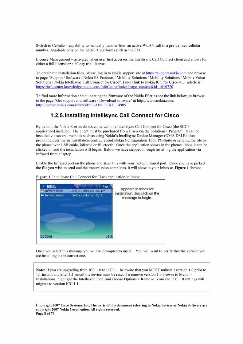
1 . 2 . 5 . I n s t a l l i n g I n t e l l i s y n c C a l l C o n n e c t f o r C i s c o B y def ault the N okia Eseries do not come with the Intellisync C all C onnect f or C isco ( the S C C P application) installed. The client must be purchased f rom C isco via the S olutions+ Program. It can be installed via several methods such as using N okia’ s Intellisync D evice M anager ( O M A D M Edition providing over the air installation/conf iguration) N okia C onf iguration Tool, PC -S uite or sending the f ile to the phone over US B cable, inf rared or B luetooth. O nce the application shows in the phones Inbox it can be clicked on and the installation will begin. B elow we have stepped through installing the application via Inf rared f rom a laptop. Enable the Inf rared port on the phone and align this with your laptop inf rared port. O nce you have picked the f ile you wish to send and the transmission completes, it will show in your Inbox as F i g u r e 1 shows: F i g u r e 1 Intellisync C all C onnect f or C isco application in Inbox
O nce you select this message you will be prompted to install. You will want to verif y that the version you are installing is the correct one. No t e : If you are upgrading f rom IC C 1.0 to IC C 1.1 be aware that you M US T uninstall version 1.0 prior to 1.1 install, and af ter 1.1 install the device must be reset. To remove version 1.0 browse to M enu > Installations, highlight the Intellisync icon, and choose O ptions > R emove. Your old IC C 1.0 settings will migrate to version IC C 1.1.
C o p y r i g h t 20 0 7 C i s c o S y s t e m s , I n c . T h e p a r t s o f t h i s d o c u m e n t r e f e r r i n g t o N o k i a d e v i c e s o r N o k i a S o f t w a r e a r e c o p y r i g h t 20 0 7 N o k i a C o r p o r a t i o n . A l l r i g h t s r e s e r v e d . P a g e 9 o f 76
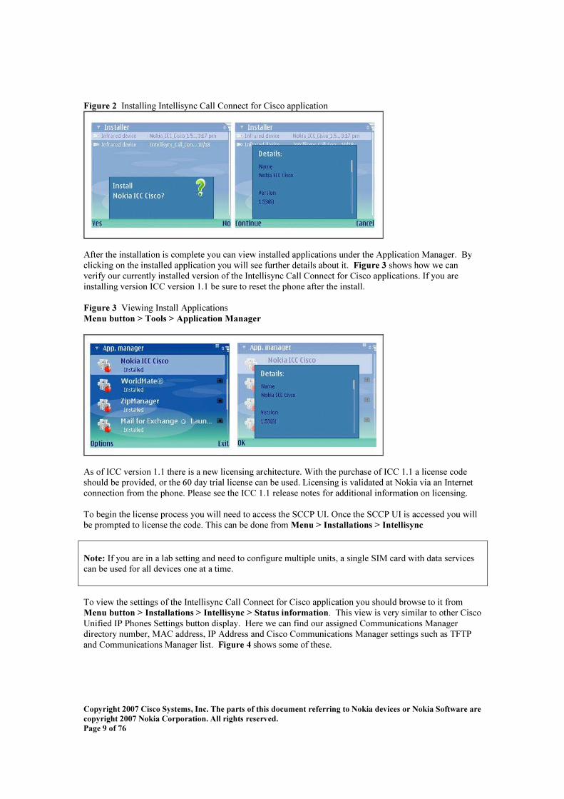
F i g u r e 2 Installing Intellisync C all C onnect f or C isco application
Af ter the installation is complete you can view installed applications under the Application M anager. B y clicking on the installed application you will see f urther details about it. F i g u r e 3 shows how we can verif y our currently installed version of the Intellisync C all C onnect f or C isco applications. If you are installing version IC C version 1.1 be sure to reset the phone af ter the install. F i g u r e 3 V iewing Install Applications M e n u bu t t o n > T o o l s > A p p l i c a t i o n M a n a g e r
As of IC C version 1.1 there is a new licensing architecture. W ith the purchase of IC C 1.1 a license code should be provided, or the 6 0 day trial license can be used. L icensing is validated at N okia via an Internet connection f rom the phone. Please see the IC C 1.1 release notes f or additional inf ormation on licensing. To begin the license process you will need to access the S C C P UI. O nce the S C C P UI is accessed you will be prompted to license the code. This can be done f rom M e n u > I n s t a l l a t i o n s > I n t e l l i s y n c No t e : If you are in a lab setting and need to conf igure multiple units, a single S IM card with data services can be used f or all devices one at a time. To view the settings of the Intellisync C all C onnect f or C isco application you should browse to it f rom M e n u bu t t o n > I n s t a l l a t i o n s > I n t e l l i s y n c > S t a t u s i n f o r m a t i o n . This view is very similar to other C isco Unif ied IP Phones S ettings button display. H ere we can f ind our assigned C ommunications M anager directory number, M AC address, IP Address and C isco C ommunications M anager settings such as TFTP and C ommunications M anager list. F i g u r e 4 shows some of these.

C o p y r i g h t 20 0 7 C i s c o S y s t e m s , I n c . T h e p a r t s o f t h i s d o c u m e n t r e f e r r i n g t o N o k i a d e v i c e s o r N o k i a S o f t w a r e a r e c o p y r i g h t 20 0 7 N o k i a C o r p o r a t i o n . A l l r i g h t s r e s e r v e d . P a g e 10 o f 76
F i g u r e 4 V iewing the S ettings of N okia Eseries M e n u bu t t o n > I n s t a l l a t i o n s > I n t e l l i s y n c C a l l C o n n e c t f o r C i s c o > S t a t u s i n f o r m a t i o n
No t e : The M AC address can be f ound 3 ways: 1) From the M enu button > Installations > Intellisync C all C onnect f or C isco > S tatus inf ormation page 2) Type in the f ollowing key seq uence at the idle screen: * # 6 2209 5 26 # 3) O n some models it is printed behind the battery.
1 . 2 . 6 . C o n f i g u r i n g t h e N o k i a E s e r i e s f o r C o m m u n i c a t i o n s M a n a g e r a n d C o m m u n i c a t i o n s M a n a g e r E x p r e s s
B ef ore beginning the conf iguration manually, verif y that Intellisync C all C onnect f or C isco application has already been installed ( see above). There are several steps needed to properly conf igure the N okia Eseries f or use on the wireless L AN , and then f or registration to C isco C ommunications M anager. All of the conf igurations are done under S ettings, which can be reached f rom M e n u bu t t o n > T o o l s > S e t t i n g s > C o n n e c t i o n . N okia encourages users to have an active S IM card inserted into the phone and to not use O f f line mode. The available settings under C onnection are:
• Access points • Access point groups • Packet data • Internet telephony settings • S IP settings • S C C P settings • D ata call • V PN • W ireless L AN • C onf igurations
To conf igure the phone to work with C isco C ommunications M anager we will be perf orming the f ollowing conf iguration tasks ( in the order listed):
• D ef ine Access Point • C onf iguring the S C C P prof ile • C onf igure an Internet telephony setting
No t e : The N okia Eseries does support S IP natively; however, at the time of this writing it has not been tested by C isco’ s 3rd party certif ication program and is unsupported.

C o p y r i g h t 20 0 7 C i s c o S y s t e m s , I n c . T h e p a r t s o f t h i s d o c u m e n t r e f e r r i n g t o N o k i a d e v i c e s o r N o k i a S o f t w a r e a r e c o p y r i g h t 20 0 7 N o k i a C o r p o r a t i o n . A l l r i g h t s r e s e r v e d . P a g e 11 o f 76
No t e : Icons on the N okia can be moved to make conf iguration easier. The steps given here assume the def ault locations at the time of writing. You may f ind it easier during daily use to move your S ettings, Internet Telephony, Intellisync C all C onnect f or C isco , C onnection M anager, and Application M anager icon’ s under one f older. If you have not already added an access point ( to connect to the wireless network) to the N okia this should be done f irst. H ere we add an access point using the def ault settings. F i g u r e 5 C onf iguring the Access Point M e n u bu t t o n > T o o l s > S e t t i n g s > C o n n e c t i o n > A c c e s s P o i n t s
N otice that we changed the D ata B earer setting to W ireless L AN and changed the W L AN N etwork N ame setting to be the S S ID of our W L AN . N ex t in F i g u r e 6 the security settings f or the Access Point need to be conf igured. In our ex ample below we step through a simple W EP conf iguration, but the N okia Eseries is capable of several f orms of authentication and encryption. S ee the appendix f or EAP-PEAP conf iguration steps.

C o p y r i g h t 20 0 7 C i s c o S y s t e m s , I n c . T h e p a r t s o f t h i s d o c u m e n t r e f e r r i n g t o N o k i a d e v i c e s o r N o k i a S o f t w a r e a r e c o p y r i g h t 20 0 7 N o k i a C o r p o r a t i o n . A l l r i g h t s r e s e r v e d . P a g e 12 o f 76
F i g u r e 6 S etting W L AN S ecurity M e n u bu t t o n > T o o l s > S e t t i n g s > C o n n e c t i o n > W L A N S e c u r i t y
W hen the N okia Eseries is not associated to an access point it will occasionally scan to see if there are W L AN s available. To adjust the delay between scan times you will need to adjust the S c a n f o r n e t w o r k s setting number W i r e l e s s L A N. This setting can decrease the connection time to C ommunications M anager once a user has roamed into an area where it was previously unregistered. F i g u r e 7 shows the steps. No t e : If the phone is associated to an access-point and uses the Always on setting, and due to TX f ailure, beacon loss, or R S S I looses its association to the access point it will aggressively attempt to re-register.

C o p y r i g h t 20 0 7 C i s c o S y s t e m s , I n c . T h e p a r t s o f t h i s d o c u m e n t r e f e r r i n g t o N o k i a d e v i c e s o r N o k i a S o f t w a r e a r e c o p y r i g h t 20 0 7 N o k i a C o r p o r a t i o n . A l l r i g h t s r e s e r v e d . P a g e 13 o f 76
F i g u r e 7 S etting W ireless L AN M e n u bu t t o n > T o o l s > S e t t i n g s > C o n n e c t i o n > W i r e l e s s L A N
The nex t req uired step is to conf igure the S C C P settings. H ere is where you combine the access point previously conf igured to an S C C P prof ile. The TFTP server can be conf igured to use D H C P via O ption 15 0 or set statically. The R egistration setting can either be W h e n n e e d e d or A l w a y s o n . W hen the R egistration setting is W h e n n e e d e d the user can manually f orce a registration attempt, but the phone will not attempt one on its own. This registration attempt is made f rom the Internet telephone application ( shown in later steps). The recommended setting f or daily use is A l w a y s o n . W ith this setting the Eseries will attempt to register to C isco C ommunications M anager when the AP conf igured f or S C C P is in range. This will allow users to roam in and out of the building without having to manually reregister their phones. W hen the Always O n setting is conf igured background W L AN scanning is activated automatically. The W h e n n e e d e d setting can be usef ul when troubleshooting. S ee F i g u r e 8 f or an overview. F i g u r e 8 C onf iguring the S C C P S ettings M e n u bu t t o n > T o o l s > S e t t i n g s > C o n n e c t i o n > S C C P s e t t i n g s

C o p y r i g h t 20 0 7 C i s c o S y s t e m s , I n c . T h e p a r t s o f t h i s d o c u m e n t r e f e r r i n g t o N o k i a d e v i c e s o r N o k i a S o f t w a r e a r e c o p y r i g h t 20 0 7 N o k i a C o r p o r a t i o n . A l l r i g h t s r e s e r v e d . P a g e 14 o f 76
N ow that your S C C P settings are added all that is lef t is to add an Internet telephony prof ile. Assuming that your N okia Eseries ( M AC address) was added to C ommunications M anager previously or auto-registration is enabled on C isco C ommunications M anager, your phone should be able to register af ter this step. If you are using C ommunications M anager Ex press and have auto register ( which is def ault) and auto assign enabled, the phone should automatically register. The pref erred method would be to set up the desired ephone # containing, mac-address , single or dual D N , type 79 70. The N okia E series will emulate a subset of the C isco 79 70 capabilities. No t e : I f y o u a r e u s i n g I C C v e r s i o n 1.0 t h e No k i a w i l l r e g i s t e r a s a 7 9 60, n o t 7 9 7 0. I n s t a l l i n g t h e No k i a .c o p f i l e a n d r e g i s t e r i n g a s a n S 60 d e v i c e i s s t i l l t h e r e c o m m e n d e d p a t h . F i g u r e 9 C onf iguring Internet Telephony S ettings M e n u bu t t o n > T o o l s > S e t t i n g s > C o n n e c t i o n > I n t e r n e t t e l e p h o n y s e t t i n g s
If you choose to set your registration to W h e n n e e d e d there is an additional step to getting the phone to register. To register you must go to the Internet Telephony application and f orce a registration attempt. W hen the phone is set to register manually it will not register again on its own if it is roamed out of W L AN coverage. This setting is primarily usef ul f or testing. F i g u r e 10 M anually R egistering to C ommunications M anager M e n u bu t t o n > C o n n e c t i v i t y > I n t e r n e t t e l e p h o n e
No t e : N okia recommends that the O f f line prof ile not be used. A S IM card is needed to avoid the O f f line prof ile. No t e : N okia recommends the Always O n setting f or the S C C P setting.

C o p y r i g h t 20 0 7 C i s c o S y s t e m s , I n c . T h e p a r t s o f t h i s d o c u m e n t r e f e r r i n g t o N o k i a d e v i c e s o r N o k i a S o f t w a r e a r e c o p y r i g h t 20 0 7 N o k i a C o r p o r a t i o n . A l l r i g h t s r e s e r v e d . P a g e 15 o f 76
1 . 2 . 7 . S u p p o r t e d C o m m u n i c a t i o n s M a n a g e r a n d C o m m u n i c a t i o n s M a n a g e r E x p r e s s V e r s i o n s
The N okia phones are supported in C ommunications M anager and C ommunications M anager Ex press as separate device types. The device types have been created such that unnecessary f eatures are not presented f or these phones. Your C ommunications M anager may need to be upgraded to the latest version to support the N okia phone. The f ollowing versions of C ommunications M anager are supported:
• 4.1( 3) • 4.2( 3) • 5 .x • 6 .x ( IC C version 1.1)
The f ollowing versions of C ommunications M anager Ex press are supported:
• 4.0 • 4.0( 1) – 12.4( 4)X C 1 • 4.0( 2) – 12.4( 11)T • 4.0( 3) – 12.4( 4)X C 4 • 4.1 and later • UC 5 00
C ommunications M anager Ex press Eseries S C C P limitations:
o As was eluded to in step eight the N okia Eseries emulate a limited subset 79 70’ s
capabilities. It is recommended that only 1 dual line D N be attached to button 1 and know other D N ’ s or button be attached to the Eseries phone. C all-f orwarding options are available, i.e. f orward to voicemail.
o W hile on S C C P W i-Fi calls, incoming G S M calls will not alert, either visually or audibly.
If voicemail has been conf igured f or the G S M number the call will go into cellular voicemail.
o W hile on a G S M call, incoming S C C P W i-Fi calls alert normally. o The M W I ( M essage W aiting Indicator) light may not re-indicate the presence of
messages if the phone is power cycled while currently illuminated.
o G 729 r8 and G 711ulaw only are supported.
1 . 2 . 8 . A d d i n g N o k i a S 6 0 D e v i c e T y p e t o C U C M Adding the N okia S 6 0 device type to C UC M is the supported method f or conf iguring N okia devices to register and perf orm correctly. To get the device type added to C UC M an installation f ile must be run. This is either and installation f ile f or the W indows 4.x version, or a .cop f ile f or 5 .x and 6 .x versions of C UC M . To obtain the installation f iles please h t t p s : / / i n f o c e n t e r . k n o w l e d g e . n o k i a . c o m / I n f o C e n t e r / i n d e x ? p a g e = c o n t e n t & i d = 1 6 1 0 7 2 0 I n s t a l l i n g C U C M .c o p F i l e s Installing the .cop f ile f or 5 .x and 6 .x are basically the same. You’ ll need an S FTP/FTP server that is reachable by C UC M , and the user credentials to access it. Adding install f iles is as simple as dropping the .cop f ile into a directory on the f ile server and pointing C UC M to it. The steps f or installing are below.

C o p y r i g h t 20 0 7 C i s c o S y s t e m s , I n c . T h e p a r t s o f t h i s d o c u m e n t r e f e r r i n g t o N o k i a d e v i c e s o r N o k i a S o f t w a r e a r e c o p y r i g h t 20 0 7 N o k i a C o r p o r a t i o n . A l l r i g h t s r e s e r v e d . P a g e 16 o f 76
First you will need to get to the O S Administration pages which can be accessed f rom the N avigation drop down.
O nce there browse to S of tware U p g r a d e s > I n s t a l l U p g r a d e . This will bring up the sof tware installation page where the FTP inf ormation can be added. Add in the correct server inf o and click Ne x t .

C o p y r i g h t 20 0 7 C i s c o S y s t e m s , I n c . T h e p a r t s o f t h i s d o c u m e n t r e f e r r i n g t o N o k i a d e v i c e s o r N o k i a S o f t w a r e a r e c o p y r i g h t 20 0 7 N o k i a C o r p o r a t i o n . A l l r i g h t s r e s e r v e d . P a g e 17 o f 76
O nce you have accessed the FTP server you should get a list of available f iles to install. S elect the N okia .cop f ile and press Ne x t .
Af ter this press Ne x t until you have the f ile downloaded and installation completes.
To verif y that the data was installed into the database simply browse back to C UC M administration, run through the steps to add a new phone, and verif y that the S 6 0 is an available device.

C o p y r i g h t 20 0 7 C i s c o S y s t e m s , I n c . T h e p a r t s o f t h i s d o c u m e n t r e f e r r i n g t o N o k i a d e v i c e s o r N o k i a S o f t w a r e a r e c o p y r i g h t 20 0 7 N o k i a C o r p o r a t i o n . A l l r i g h t s r e s e r v e d . P a g e 18 o f 76
1 . 2 . 9 . N o k i a E s e r i e s T F T P I n t e r a c t i o n C isco’ s TFTP server is not used f or downloading f irmware, as is the case with C isco IP Phones. Instead the N okia Eseries only use relevant conf iguration options in the conf iguration f ile. To update the f irmware of your N okia Eseries you will need to contact your local N okia representative f or f lashing or use the online tools. To f ind more inf ormation about updating the f irmware of the N okia ES eries see the link below, or browse to the page " G et support and sof tware / D ownload sof tware" at http://www.nokia.com: http://europe.nokia.com/link? cid= PL AIN _ TEX T_ 149 05
1 . 2 . 1 0 . D i a l i n g I n t e r n a t i o n a l D e s t i n a t i o n s W hen a user dials an international destination f rom a mobile device, the generally accepted practice is to insert a plus “ + ” sign at the beginning. In current versions of C ommunications M anager the “ + ” sign is not recogniz ed as a digit that can be dialed. To address this issue, N okia converts the “ + ” to two z eros “ 00”, which can be added to a route pattern in C ommunications M anager f or international dialing. This can be updated to other patterns using N okia Intellisync D evice M anager.

C o p y r i g h t 20 0 7 C i s c o S y s t e m s , I n c . T h e p a r t s o f t h i s d o c u m e n t r e f e r r i n g t o N o k i a d e v i c e s o r N o k i a S o f t w a r e a r e c o p y r i g h t 20 0 7 N o k i a C o r p o r a t i o n . A l l r i g h t s r e s e r v e d . P a g e 19 o f 76
1.3 . R F B a s i c s a n d S i t e S u r v e y The N okia Eseries devices are 8 02.11b and 8 02.11g compliant. This section covers the basic R F inf ormation necessary to properly deploy the N okia Eseries phones in a C isco Unif ied W L AN network. No t e : The N okia ES eries support 8 02.15 B luetooth ( B T) and 8 02.11b/g. B ecause both radios share the same antenna and f req uency band, a B T earpiece should not be used with these phones when they in 8 02.11 b/g mode. S ignif icant degradation of voice q uality can result. A chart of the B T and 8 02.11b/g f req uencies is shown in appendix A. A B T headset connected to the phone during a call causes a poor call q uality that may degrade to the point of a dropped call. The B T transmission of will also negatively af f ect the q uality of other nearby calls that are using 8 02.11b/g. C alls as f ar away as 75 f eet f rom B T maybe af f ected. A laptop user that has B T enabled on the laptop f or communication to a B T mouse will also ex perience lower q uality V oW L AN calls. C harts of jitter created on a call with a B T enabled versus a call without a B T enabled are shown in appendix B . All sites using 8 02.11b/g phones should be f req uency scanned and surveyed f or interf erence to determine where perf ormance challenges will be due to interf erence. N okia phones at this time do not support call limiting per R F channel. They do not support pre-emptive or assisted roaming logic. B ecause channel capacity and advanced L 2 roaming is not processed by the phones R F channels may become over subscribed and call q uality can degrade. The N okia Eseries conf orm to the data rate settings of the access point. If the access point is conf igured f or a max imum data rate of 24M bps the client does not transmit at above that rate. If the max imum is set f or ex ample 12M bps and the phone is within a distance of the access point that supports 24M bps it use the 24M bps data rate. S uch behavior is not uncommon in W iFi devices with 11g data rates. If there are no 11g data rates enable on the access point, then the phone will only do 11b rates. This is important when designing cells f or capacity instead of coverage. The N okia phone was tested with the new C isco AP1240 with diversity enabled and using the AIR -AN T49 41 antennas. The N okia clients at 36 M bps had a signal of -6 8 and at a noise level of -9 6 had a 1% packet error rate ( PER ) at the distance of 70 f eet in an open of f ice of typical cubes. The coverage cell edge at the 36 M bps is -6 8 . At distances greater than 70 f eet or a noise level greater than -9 6 the PER went higher that 1% . This is provided as an observation and is not a design recommendation. The N okia phones have internal W iFi antennas. The user may inadvertently place their hand over antenna which reduce receive signal strength and transmit signal strength by 4dB m. There are charts in appendix C . A common rule of thumb is a 9 dB loss in an indoor environment will reduce by half the coverage of a 2.4G H z radio. It is recommended that the coverage be designed with this condition in mind. K ey W L AN design notes f or N okia E6 1 phones:
• If the W L AN had been caref ully design to the 79 20 design guide of a cell edge of -6 7dB m f or 11M bps then the N okia phone should be able to work in that coverage cell, with the AP1240 and AP1230 at a 8 02.11g data rate of 12M bps. The AP1230 and AP1240 support 8 02.11g rates with a max imum transmit power of 5 0mW ( 17dB m). The receive sensitivity of the radios is also better than previous 8 02.11g rates. The combination of increased transmit power and receiver sensitivity give these two access point a coverage area at the 8 02.11g rate of 12M bps that is eq ual to the previous access point coverage of 8 02.11b rate of 11M bps.

C o p y r i g h t 20 0 7 C i s c o S y s t e m s , I n c . T h e p a r t s o f t h i s d o c u m e n t r e f e r r i n g t o N o k i a d e v i c e s o r N o k i a S o f t w a r e a r e c o p y r i g h t 20 0 7 N o k i a C o r p o r a t i o n . A l l r i g h t s r e s e r v e d . P a g e 20 o f 76
• All indoor installations need diversity antenna support on the access point. S ignal strength alone will not provide good signal q uality. Indoors the 2.4G H z signal of the radios will bounce of f some objects and be absorbed at various levels by other objects. D iversity support signif icantly improves throughput by reducing retries, which particularly important to an application like voice. W ithout diversity antenna support on the phones it becomes more important to have diversity enabled on the access points. The antenna appendix lists recommended antennas.
• The antenna placement should be selective. Antennas should not be mounted near metal objects. Putting transmission and reception of signals near metal increases multipath problems. S ee the antenna appendix f or recommended antenna installation.
• S ame channel separation is an important design consideration. C hannel utiliz ation af f ects the numbers of calls on the channel and channel utiliz ation. C hannel separation also reduces the noise f loor. The channel is the collision domain.
• The C L I and G UI of the autonomous and L W APP access points should be used to verif y the signal level and data rate of the phones as seen by the access points. The coverage of the phone during survey and coverage checks should be done with active calls.
• W hen there needs to be a high density of calls in a given f loor space. The best way to reduce cell siz e is to reduce transmit power of all radios. That is both access point and phones. W hile f aster data rates have smaller cells, most clients will use the data rate they want to use and not the data rates set on the access point. Theref ore it is better to plan cell siz e by power settings. The recommended means f or managing the transmit power of the phone and other clients is “ C lient Power L ocal” on the autonomous access points. The L W APP access points def ault to that method. This means the access points tell the clients to use the transmit power as the access point.
For a detailed discussion on V oice over W L AN design please see the M obility D esign G uide at: http://www.cisco.com/en/US /netsol/ns6 5 6 /networking_ solutions_ program_ home.html
1 . 3 . 1 . D i f f e r e n t D e p l o y m e n t T y p e s o f O v e r l a p p i n g W L A N H ow much overlapping W L AN coverage you set in your wireless network depends on the usage. W ireless networks can be deployed f or L ocation-B ased S ervices, V oice, or D ata-O nly networks. The dif f erence is in the pattern that the APs are laid out in and the amount of R F overlap in the coverage area. If the deployment has voice and data, then f ollow the voice deployment guidelines. If the deployment has V oice, data and L ocation B ased S ervices, f ollow the voice recommendations and f ill in the coverage area with monitor mode APs. D a t a -O n l y D e p l o y m e n t s D ata only deployments will not req uire a large amount of overlap ( above 10% overlap). If you have lower data rates enabled, 8 02.11 clients will respond to a lower signal f rom a nearby AP, should one f ail, by stepping down their data rate and taking a longer time to transmit or roaming to a new AP. W hile the smaller overlap minimiz e co-channel interf erence, data clients will drop packets as they shif t data rate or roam to a new AP. This will slow data throughput on the wireless network. The req uired overlap will be determined by the W L AN data rate req uirement discussed in the subsection below. M inimal overlap is req uired f or data-only networks which allow all data rates. For data-only networks, the rule of thumb f or separation of APs is typically 120-130 f eet. B ut, when making your estimation f or AP separation, remember to f actor in objects that af f ect R F coverage such as wall densities, machinery, elevators, or even wide open space with steel cages, as your results may vary depending on the R F environment. R adio R esource M anagement ( R R M ) has been developed f or this type of deployment and is very usef ul f or controlling the R F coverage.

C o p y r i g h t 20 0 7 C i s c o S y s t e m s , I n c . T h e p a r t s o f t h i s d o c u m e n t r e f e r r i n g t o N o k i a d e v i c e s o r N o k i a S o f t w a r e a r e c o p y r i g h t 20 0 7 N o k i a C o r p o r a t i o n . A l l r i g h t s r e s e r v e d . P a g e 21 o f 76
V o i c e D e p l o y m e n t s F i g u r e 11 shows the voice network pattern and overlap. The APs are grouped closer together and have more overlap than a data-only installation because voice clients need to roam to a better AP bef ore dropping packets. Although only one AP is req uired to handle its def ined area of the coverage area f or a voice deployment, it is recommended that you have 2 AP' s on non-overlapping channels. For the N okia W i-FI voice deployment, it is recommended that you have a R eceived S ignal S trength Indication ( R S S I) above -6 7dB m at all time in your installation. This is to ensure that the V O IP phone has good reception as well as providing coverage and enhances roaming ability f or the phone. Pre and post site surveys are of ten helpf ul in designing AP coverage. W hen V oIP applications are involved, the rule of thumb is 100' separation typically. W hen making your estimation f or separation, remember to f actor in objects that af f ect R F coverage such as wall densities, machinery, elevators, or even wide open space with steel cages, as your results may vary depending on the R F environment. Please see the V oice section of the C isco Enterprise M obility D esign G uide f or f urther reading on deploying V oice of W L AN . F i g u r e 11 S ingle Floor S ite S urvey f or V oice
No t e : This is the cell perspective f rom the access point. Each phone has its own cell. L ooking at channel 6 in the lower right corner, it can be seen that phone associated to that access point could have channel overlap with the channel 6 access point in the middle. It is recommended that you have a R eceived S ignal S trength Indication ( R S S I) above -6 7dB m at all time in your installation, at 12M b. The same channels need to be transmit power adjusted so that they separated by 19 dB m. This reduces the siz e of the collision domain and will reduce a noise f loor ef f ect that the like channels will have on each other.

C o p y r i g h t 20 0 7 C i s c o S y s t e m s , I n c . T h e p a r t s o f t h i s d o c u m e n t r e f e r r i n g t o N o k i a d e v i c e s o r N o k i a S o f t w a r e a r e c o p y r i g h t 20 0 7 N o k i a C o r p o r a t i o n . A l l r i g h t s r e s e r v e d . P a g e 22 o f 76
F i g u r e 12 W L AN C ell S eparation
1 . 3 . 2 . R e c o m m e n d e d E n v i r o n m e n t f o r t h e N o k i a E s e r i e s The N okia Eseries uses R S S I ( R eceived S ignal S trength Indication), TX f ailure, and beacon loss as its primary tools f or making roaming and association decisions. In order to have a successf ul wireless voice deployment it is highly recommended that you conduct a site survey specif ically f or voice due to the uniq ueness of voice deployments. W hen deploying an environment f or the N okia Eseries observe the f ollowing guidelines:
• C isco recommends that you have no more than approx imately 15 – 25 devices per AP. • M aintain a minimum speed of 12M b. Enabling lower speeds will result in lower call capacity. • D eploy a minimum of two AP’ s on no-overlapping channels, with an R S S I that is greater than
-67 d B m f or speeds of 12M b. • S eparate overlapping channel sets by approx imately 19 dB m. • S trive to maintain the highest possible speed throughout your coverage area. • O verlap coverage areas by a minimum of 20% to ensure smooth roaming. • W ith optimal settings and minimal data throughput 7 call legs per AP at 12 M b can be
achieved. H igher rates have not yet been verif ied. A call leg is a single phone on a call. A call between two phones associated to the same AP counts as two active call legs.
• Ensure your packet error rate and beacon loss is 1% or less.
No t e : If enabled on the AP, D ynamic Transmit Power C ontrol ( D TPC ) allows the AP to broadcast transmit power, and clients can automatically conf igure themselves to that power while associated with that AP. The C isco IO S command f or enabling D TPC is p o w e r c l i e n t and was f irst introduced in C isco IO S version 12.2( 4)J A. C lients operating on 8 02.11b can operate on AP’ s that support 8 02.11g as well, assuming that the 8 02.11b speeds are enabled. H owever, mix ing these slower clients can signif icantly reduce the throughput f or the f aster 8 02.11g users, and can reduce the number of calls per AP. For a discussion on mix ing 8 02.11b and 8 02.11g clients see: http://www.cisco.com/en/US /products/hw/wireless/ps45 70/products_ white_ paper09 18 6 a008 01d6 1a3.shtml

C o p y r i g h t 20 0 7 C i s c o S y s t e m s , I n c . T h e p a r t s o f t h i s d o c u m e n t r e f e r r i n g t o N o k i a d e v i c e s o r N o k i a S o f t w a r e a r e c o p y r i g h t 20 0 7 N o k i a C o r p o r a t i o n . A l l r i g h t s r e s e r v e d . P a g e 23 o f 76
1.4 . N o k i a R F T o o l s
There are several tools on the N okia Eseries f or evaluating the availability and security of the wireless environment. W hen the N okia Eseries is in the presence of a wireless network that is not hidden ( broadcasting its S S ID ) there will be an indication on the screen. If the phone has not yet associate to the W L AN , the indicator box es will not be f illed in. W hen this icon is shown the users immediately knows that there is an access point in the area and it is advertising its S S ID . For deployment of the N okia Eseries it is recommended that you enable broadcasting of the S S ID . This has been f ound to signif icantly improve phone perf ormance on the W L AN . W hen the phone associates to an access point the icon box es change to a f illed in state as show in F i g u r e 13. F i g u r e 13 W L AN Association Icon
Af ter associating with the access point and registering to C ommunications M anager, a new icon will be shown below in Figure 14. F i g u r e 14 R egistration Icon
1 . 4 . 1 . U s i n g C o n n e c t i o n M a n a g e r The C onnection M anager is comprised of two important applications, the Active D ata C onnections and the Available W L AN application. These tools give users a detailed view of wireless environment.

C o p y r i g h t 20 0 7 C i s c o S y s t e m s , I n c . T h e p a r t s o f t h i s d o c u m e n t r e f e r r i n g t o N o k i a d e v i c e s o r N o k i a S o f t w a r e a r e c o p y r i g h t 20 0 7 N o k i a C o r p o r a t i o n . A l l r i g h t s r e s e r v e d . P a g e 24 o f 76
A v a i l a bl e W L A N B y selecting the Available W L AN utility you can q uickly determine all of the networks that the phone is able to sense via S S ID s that are being broadcast, the approx imate signal level, whether the AP is open or secured, and if your phone is currently associated to that AP. In F i g u r e 15 we can see that there are currently two W L AN s in the area, that the signal is low on the guestnet and higher on nokia3. W hen a network is secured it will show as having a lock icon on it and that we are associated to that network currently. N otice that we are currently associated to the nokia3 network, which is indicated by the associated icon in a circle nex t to that wireless network. F i g u r e 15 N okia Available W L AN M e n u bu t t o n > C o n n e c t i v i t y > C o n n . M a n a g e r > A v a i l a bl e W L A N
If we now highlight and open an S S ID we can see more details about this network including the S S ID name, the security type, speed, how many AP’ s are available with this S S ID , and also the signal strength. S ee the section labeled Evaluating S ignal S trength f or more details on how this can assist users. A c t i v e C o n n e c t i o n s The Active C onnections tool presents a very detailed view of our current wireless connection. The key points of this tool are the S tatus and TX Power. The status of an active connection will show the received signal strength in a percentage generically as S trong, M edium, or W eak. W hen this document ref erences a recommended signal strength percentage, it is ref erring to it as shown in this tool. The TX Power indication is usef ul f or ensuring that the AP and phone have synchroniz ed their transmit power levels. F i g u r e 16 N okia Active D ata C onnections M e n u bu t t o n > C o n n e c t i v i t y > C o n n . M a n a g e r > A c t . D a t a c o n n .

C o p y r i g h t 20 0 7 C i s c o S y s t e m s , I n c . T h e p a r t s o f t h i s d o c u m e n t r e f e r r i n g t o N o k i a d e v i c e s o r N o k i a S o f t w a r e a r e c o p y r i g h t 20 0 7 N o k i a C o r p o r a t i o n . A l l r i g h t s r e s e r v e d . P a g e 25 o f 76
E v a l u a t i n g S i g n a l S t r e n g t h The N okia Eseries does not display its W L AN signal strength indication in dB m. B elow in Figure 18 is an approx imation of shown percentage to dB m. Use this to assist in determining if the phone is receiving adeq uate signal. It should be noted that there can be signif icant dif f erence in signal level when simply viewing the phone and when it is placed to the ear with a hand covering the phone. It is recommended to keep the phone in the S trong area of coverage. S trong indicates signal strength of 6 7 – 100% . If you are operating at a rate of 48 – 5 4M b then the recommended signal strength is 75 % and higher. This level of signal will help the phone to give good voice q uality and roam more smoothly. F i g u r e 17 N okia D isplayed S ignal % to dB m C orrelation C hart
1 . 4 . 2 . S u p p o r t e d S e c u r i t y M e c h a n i s m s The N okia Eseries supports the f ollowing key management types:
• W EP 6 4bit • W EP 128 bit • 8 02.1X with dynamic W EP • W PA-PS K • W PA2-PS K • W PA-Enterprise • W PA2-Enterprise • C C K M
The f ollowing EAP types are supported as well: • EAP-TL S • EAP-PEAP • EAP-L EAP • EAP-TTL S • EAP-S IM • EAP-AK A

C o p y r i g h t 20 0 7 C i s c o S y s t e m s , I n c . T h e p a r t s o f t h i s d o c u m e n t r e f e r r i n g t o N o k i a d e v i c e s o r N o k i a S o f t w a r e a r e c o p y r i g h t 20 0 7 N o k i a C o r p o r a t i o n . A l l r i g h t s r e s e r v e d . P a g e 26 o f 76
• EAP-M S C H APv2 • EAP-G TC • M S C H APv2
No t e : C urrently N okia does not support EAP-FAS T. The f ollowing encryption methods are supported:
• W EP 6 4bit • W EP 128 bit • TK IP • AES
No t e : To f acilitate f aster roaming C isco recommends that C C K M ( C isco C entraliz ed K ey M anagement be utiliz ed.
1.5 . R o a m i n g An integral concept f or wireless networks is device roaming. It is important to understand what roaming is, how and when it occurs, what types of roaming there are, and how the types dif f er. O ne of the obvious benef its of W L AN IP Phones compared to wired IP Phones is the ability of the user to move f rom place to place while having a conversation. B ut unlike cellular phone services, where coverage areas are usually nationwide or international, W L AN IP Phones have smaller coverage areas. In addition, administrators of W L AN IP Phone networks need to understand and consider their IP addressing schemes bef ore deploying W L AN IP Phones. They need to consider how W L AN IP Phone coverage overlays with the L ayer 2 and L ayer 3 addressing within the IP network. A L ayer 2 network is def ined as a single IP subnet and broadcast domain, while a L ayer 3 network is def ined as the combination of multiple IP subnets and broadcast domains.
1 . 5 . 1 . L a y e r 2 R o a m i n g In voice systems, roaming usually ref ers to physical movement and the locations f rom which a call can originate. For 8 02.11 data networks, roaming also ref ers to physical movement, but it is of ten associated with data connectivity while physically moving. This type of roaming does not include moving f rom the 8 02.11 environment to the cellular network. The N okia Eseries does not support roaming f rom W i-Fi to cellular. At this time both the G S M and 8 02.11 radios are active at the same time. N okia uses TX f ailure, beacon loss, and R S S I ( received signal strength) to determine whether or not to roam. An association will be made to the AP with the highest R S S I. W hen the phone is associated to a W L AN network it does not perf orm periodic background scanning by def ault. If the R S S I drops below -8 0dB ( 40% - 5 0% in C onnection M anager) a scan of all channels will begin. B ecause of this threshold, if you have moved within range of an access point with better signal strength, but you are still currently above -8 0dB the phone will not initiate roaming. It is recommended that you strive to maintain a consistent minimum speed throughout your coverage areas. M ix ing speeds can cause phones to stay associated to those AP’ s even though they are in range of better.

C o p y r i g h t 20 0 7 C i s c o S y s t e m s , I n c . T h e p a r t s o f t h i s d o c u m e n t r e f e r r i n g t o N o k i a d e v i c e s o r N o k i a S o f t w a r e a r e c o p y r i g h t 20 0 7 N o k i a C o r p o r a t i o n . A l l r i g h t s r e s e r v e d . P a g e 27 o f 76
F i g u r e 18 illustrates this problem. AP1 has been conf igured f or all O FD M rates of 12M b and higher. AP’ s 2 and 3 are conf igured f or 5 4mb. All AP’ s have the same transmit power level. N otice that because 12M b req uires less f req uency it has a much larger coverage area than 5 4M b does. This causes the phone to stay associated to AP1 even though AP2 is in closer prox imity and has a higher signal and available speed. To f acilitate smooth roaming it is recommended that C isco C entraliz ed K ey M anagement ( C C K M ) be implemented in the W L AN . Using C C K M req uires 8 02.1x authentication with EAP-L EAP, PEAP, EAP-TL S , or EAP-TTL S . The use of C C K M can signif icantly speed up roaming between access points by reducing the need f or clients to reauthenticate against the authentication server when a roam is initiated due to an R S S I threshold being ex ceeded. For an overview of C C K M see the link below: http://www.cisco.com/web/partners/pr46 /pr147/partners_ pgm_ brochure.html D esign your V oW L AN network to the minimum speed that is conf igured. For ex ample, if you access points are conf igured f or 24M b and higher, you should design your coverage overlap and estimate calls per AP based on this minimum value. If the phones are in a coverage area allowing them to transmit at 5 4M b it will increase the potential number of calls per AP, but unless the entire network is f ix ed at this speed it is impossible to accurately estimate the call capacity of a mix ed environment. F i g u r e 18 W ireless C overage Area
1 . 5 . 2 . R o a m i n g b e t w e e n W L A N a n d G S M C urrently there is no capability f or roaming between the G S M network and the wireless L AN . If you are on an active W L AN call, and roam out of coverage area your call will be disconnected.
1 . 5 . 3 . R e g i s t r a t i o n B e h a v i o r The W L AN scanning time is determined by the W ireless L AN setting f rom M e n u bu t t o n > T o o l s > S e t t i n g s > C o n n e c t i o n > W i r e l e s s L A N. This setting determines how of ten the N okia phones will scan f or W L AN s if it is currently not associated to an access point, and the def ault f or the setting is 5 minutes. If a N okia ES eries is registered to C ommunications M anager and the W L AN connection is dropped, the S C C P client application will change the background scanning time to 30 seconds f or the nex t 5 minutes. This allows the phone to q uickly f ind a new access point and reregister to C ommunications M anager. If an
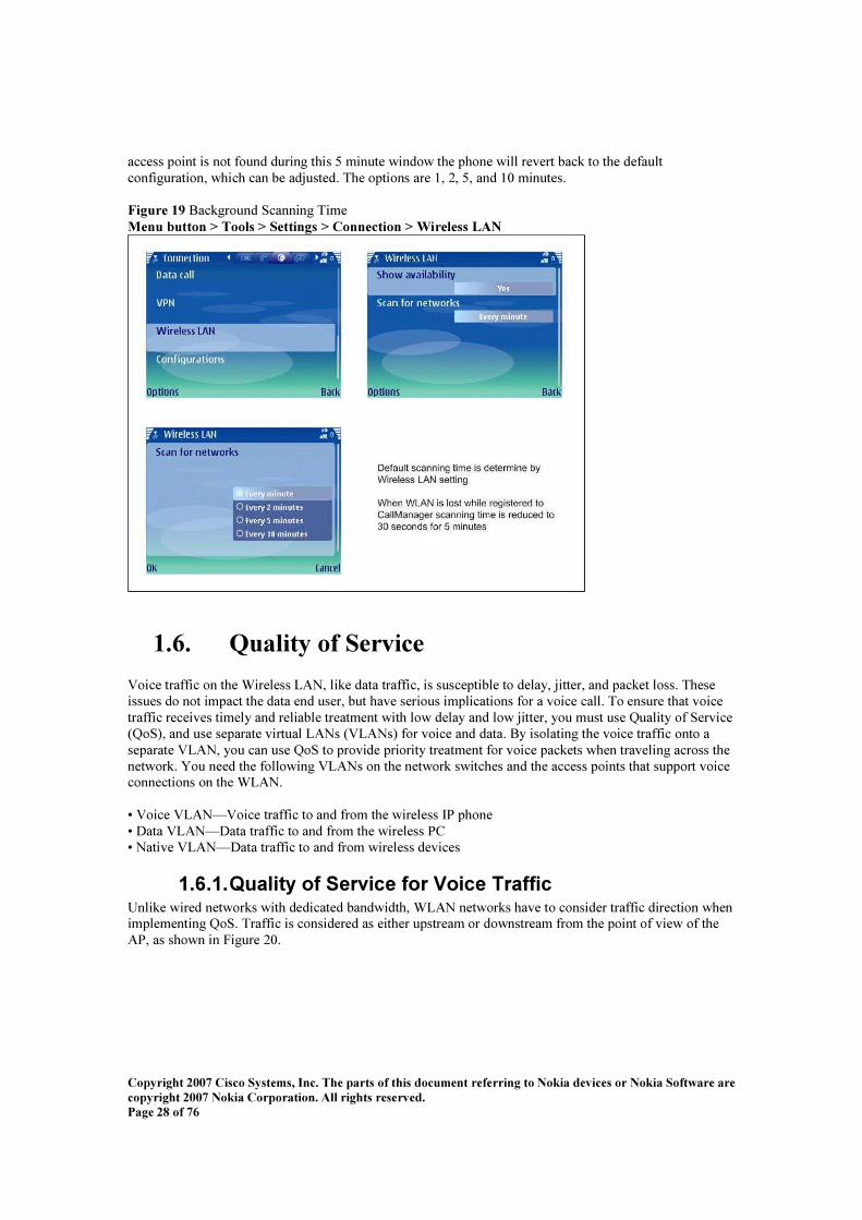
C o p y r i g h t 20 0 7 C i s c o S y s t e m s , I n c . T h e p a r t s o f t h i s d o c u m e n t r e f e r r i n g t o N o k i a d e v i c e s o r N o k i a S o f t w a r e a r e c o p y r i g h t 20 0 7 N o k i a C o r p o r a t i o n . A l l r i g h t s r e s e r v e d . P a g e 28 o f 76
access point is not f ound during this 5 minute window the phone will revert back to the def ault conf iguration, which can be adjusted. The options are 1, 2, 5 , and 10 minutes. F i g u r e 19 B ackground S canning Time M e n u bu t t o n > T o o l s > S e t t i n g s > C o n n e c t i o n > W i r e l e s s L A N
1.6 . Q u a l i t y o f S e r v i c e V oice traf f ic on the W ireless L AN , like data traf f ic, is susceptible to delay, jitter, and packet loss. These issues do not impact the data end user, but have serious implications f or a voice call. To ensure that voice traf f ic receives timely and reliable treatment with low delay and low jitter, you must use Q uality of S ervice ( Q oS ), and use separate virtual L AN s ( V L AN s) f or voice and data. B y isolating the voice traf f ic onto a separate V L AN , you can use Q oS to provide priority treatment f or voice packets when traveling across the network. You need the f ollowing V L AN s on the network switches and the access points that support voice connections on the W L AN . • V oice V L AN —V oice traf f ic to and f rom the wireless IP phone • D ata V L AN —D ata traf f ic to and f rom the wireless PC • N ative V L AN —D ata traf f ic to and f rom wireless devices
1 . 6 . 1 . Q u a l i t y o f S e r v i c e f o r V o i c e T r a f f i c Unlike wired networks with dedicated bandwidth, W L AN networks have to consider traf f ic direction when implementing Q oS . Traf f ic is considered as either upstream or downstream f rom the point of view of the AP, as shown in Figure 20.

C o p y r i g h t 20 0 7 C i s c o S y s t e m s , I n c . T h e p a r t s o f t h i s d o c u m e n t r e f e r r i n g t o N o k i a d e v i c e s o r N o k i a S o f t w a r e a r e c o p y r i g h t 20 0 7 N o k i a C o r p o r a t i o n . A l l r i g h t s r e s e r v e d . P a g e 29 o f 76
F i g u r e 20 AP Q uality of S ervice
The data V L AN should not be V L AN 1which is typically the def ault native V L AN f or all network devices. Assign separate S S ID s to the voice and to the data V L AN s. You can also conf igure a separate management V L AN in the W L AN , but do not associate an S S ID with the management V L AN . B y separating the phones onto a voice V L AN and marking voice packets with higher C oS , you can ensure that voice traf f ic gets priority treatment over data traf f ic. You can management traf f ic resulting in lower delay and f ewer lost packets. B eginning with C isco IO S R elease 12.2( 11)J A, C isco Aironet APs support ED C F-type Q oS , with up to eight q ueues f or downstream ( toward the 8 02.11b clients) Q oS . These q ueues can be allocated in any of the f ollowing ways: • B ased on ToS or D S C P settings of the packets • B ased on L ayer 2 or L ayer 3 access lists • B ased on V L AN • B ased on dynamic registration of devices such as the C isco 79 20 W ireless IP Phone V oice ( R TP) and signaling ( S C C P) traf f ic should be placed into the highest priority q ueue, and all data traf f ic should be placed into a best-ef f ort q ueue. W hile 8 02.11b ED C F does not guarantee that voice traf f ic will be protected f rom data traf f ic, using this q ueuing model should provide the best statistical results f or voice Q oS . No t e : The N okia Eseries phones mark the S C C P signaling packets with a D S C P value of 24 and R TP packets with D S C P 46 . To improve the reliability of voice transmissions in a non-deterministic environment the N okia Eseries is W i-Fi M ultimedia ( W M M ) capable. W M M enables dif f erentiated services f or voice, video, best ef f ort data and other traf f ic. H owever, in order f or these dif f erentiated services to provide suf f icient Q uality of S ervice f or voice packets, only a certain amount of voice bandwidth can be serviced or admitted on a channel at any one time. If the network can handle " N " voice calls with reserved bandwidth, when the amount of voice traf f ic is increased beyond this limit, i.e. to the " N + 1" call, the q uality of all calls will suf f er. No t e : The N okia Eseries is C C X version 3 compliant and supports W i-Fi M ultimedia ( W M M ). Implementing Q uality of S ervice in the connected Ethernet switch is highly recommended to maintain good voice q uality. To conf igure the Q oS correctly on the AP see the section above labeled Interacting with the C isco Access Point.

C o p y r i g h t 20 0 7 C i s c o S y s t e m s , I n c . T h e p a r t s o f t h i s d o c u m e n t r e f e r r i n g t o N o k i a d e v i c e s o r N o k i a S o f t w a r e a r e c o p y r i g h t 20 0 7 N o k i a C o r p o r a t i o n . A l l r i g h t s r e s e r v e d . P a g e 30 o f 76
Individual conf igurations will vary; however, ex amples are given below of potential switch Q oS commands to implement. mls q os mls q os map cos-dscp 0 8 16 24 34 46 48 5 6 mls q os map ip-prec-dscp 0 8 16 24 34 46 48 5 6 interf ace FastEthernet0/10 switchport access vlan 11 switchport mode access switchport voice vlan 111 no ip address mls q os trust dscp wrr-q ueue cos-map 1 1 wrr-q ueue cos-map 2 wrr-q ueue cos-map 3 2 3 4 6 7 wrr-q ueue cos-map 4 5 priority-q ueue out spanning-tree portf ast No t e : If you are using a C isco C atalyst 4000 S eries S witch as the main router in the network, ensure that it contains, at a minimum, either a S upervisor Engine 2+ ( S UP2+ ) or S upervisor Engine 3 ( S UP3) module. The S UP1 or S UP2 module can cause roaming delays, as can the C isco C atalyst 29 48 G , 29 8 0G , 29 8 0G -A, 49 12, and 29 48 G -G E-TX switches. No t e : Implementing proper Q oS on the access point and Ethernet switch is highly recommended. The S C C P signaling messages are marked with D S C P 24 and R TP packets are marked with D S C P 46 which match the D S C P markings of wired phones.
1.7 . U n d e r s t a n d i n g Di f f e r e n c e s B e t w e e n N o k i a E s e r i e s a n d Ci s c o W i r e l e s s I P P h o n e s
The N okia Eseries and C isco W ireless IP Phones have many similar capabilities; however, there are many key dif f erences that need to be considered. The C isco 79 20 and 79 21 wireless IP phones are designed to behave very similar to C isco’ s desk phones, such as the 79 6 0 and 79 70. This means that the access services such as directory and X M L services in the same manner. Even though the N okia Eseries devices do register as an S C C P endpoint, they behave in the same f ashion as other G S M devices, and are optimiz ed f or cellular and data usage rather than just V oW L AN as the 79 20 and 79 21 are. Table 4 lists key f eature dif f erences.

C o p y r i g h t 20 0 7 C i s c o S y s t e m s , I n c . T h e p a r t s o f t h i s d o c u m e n t r e f e r r i n g t o N o k i a d e v i c e s o r N o k i a S o f t w a r e a r e c o p y r i g h t 20 0 7 N o k i a C o r p o r a t i o n . A l l r i g h t s r e s e r v e d . P a g e 31 o f 76
T a bl e 4 N okia Eseries and C isco W ireless IP Phone Features F e a t u r e No k i a E s e r i e s C i s c o W i r e l e s s I P
P h o n e s No t e s
D irectory E5 1 O nly Uses X M L directory lookup
X M L N ot Available Available X M L can be used on C isco phones f or application and directory integration
IPC C Ex press support N ot S upported S upported N okia Eseries is not intended f or call center usage.
TFTP f irmware download
N ot S upported S upported Firmware must be obtained f rom N okia, not C ommunications M anager
TFTP conf iguration S upported S upported G S M / G PR S capability S upported N ot S upported C isco wireless IP
phones are considered ‘ singlemode’ and do not support cellular services
S R S T f allback N ot S upported S upported S C C P signaling S upported S upported S IP signaling Available, but N ot
S upported on C ommunications M anager
N ot Available
Encryption W EP, TK IP, AES W EP, TK IP, AES W PA2 available on C isco 79 21 only
Authentication EAP-TL S , EAP-PEAP, EAP-L EAP, EAP-TTL S , EAP-S IM , EAP-AK A, EAP-M S C H APv2, EAP-G TC
W PA, EAP-FAS T
Q oS W M M W M M , C D P C all Admission C ontrol N ot S upported TS PEC , Q B S S 8 02.11b/g S upported S upported 8 02.11g on 79 21 only 8 02.11a N ot S upported S upported 79 21 only R oaming S ignal strength and
packet loss S ignal strength, packet loss, and Q oS
The N okia Eseries will not roam unless the signal strength or packet loss ex ceed preconf igured thresholds
Power save U-APS D ( E5 1, via D evice M anager S erver f or other modesl), PS -PO L L
U-APS D , PS -PO L L

C o p y r i g h t 20 0 7 C i s c o S y s t e m s , I n c . T h e p a r t s o f t h i s d o c u m e n t r e f e r r i n g t o N o k i a d e v i c e s o r N o k i a S o f t w a r e a r e c o p y r i g h t 20 0 7 N o k i a C o r p o r a t i o n . A l l r i g h t s r e s e r v e d . P a g e 32 o f 76
1.8 . U p g r a d i n g T o V e r s i o n 1.1 U s i n g B AT Users who have already deployed on Intellisync C all C onnect f or C isco 1.0 ( IC C 1.0) may need to eventually upgrade to version IC C 1.1. In version 1.0 registration of N okia ES eries as a 79 6 0 device type could be used due to a lack of S 6 0 device type in C UC M E. H owever, in version 1.1 this has been disallowed in C UM C f or several reasons:
• D evice type has changed to a 79 70 in C UC M E • Incorrect conf iguration of 79 6 0 in C UC M could result in registration f ailure • L icensing issues
If you have already conf igured your N okia dual-modes as 79 6 0’ s in C UC M and upgrade the S C C P application to version 1.1 your phones will f ail to register correctly to C UC M due to a device type mis-match. O nce version 1.1 is installed the N okia Eseries will attempt to register as a 79 70 or S 6 0 device type, not a 79 6 0, and auto-registration will f ail due to the M AC address already being present in the database. No t e : Upgrading the N okia dual-mode to IC C version 1.1 B EFO R E migrating them to the S 6 0 device type will cause registration f ailures f or those devices. IC C version 1.1 changes device registration type f rom 79 6 0 or S 6 0 to 79 70 or S 6 0. The supported C UC M method is as a N okia S 6 0 device type. As of version 6 .0, C UC M does not support a method of migrating devices f rom one device type to a dif f erent device type. To do this req uires that the current device prof ile be deleted and a new device added with the same M AC address. Automating this process can be done via B AT, though there are some caveats:
• User associations are not migrated • M obilityM anager conf igurations are not automatically migrated • D ue to D L U dif f erences between 79 6 0’ s and S 6 0’ s, it is possible to ex haust the D L U pool
If you have a small number of devices it may be easy to update them one at a time, by deleting and re-adding them. H owever, f or larger numbers of phones we have tried to provide a more automated method. The upgrade f rom IC C 1.0 to IC C 1.1 is unlike that of typical devices registered to C UC M due to the f irmware not being controlled by the TFTP process. Instead, users are f ree to upgrade their N okia’ s to version 1.1 regardless of what has been done on C UC M . For this reason administrators may want to proactively migrate their devices to the S 6 0 device type ( which does N O T req uire version 1.1) to prevent potential phone outages. W hat we have provided below is a step-by-step ex ample of how to migrate N okia’ s f rom 79 6 0 to S 6 0 devices. This assumes that the correct installation of the N okia S 6 0 device type has been added to C UC M . To obtain the installation f iles, please, log in to N okia support site at https://support.nokia.com and browse to page " S upport / S of tware / N okia ES Products / M obility S olutions / M obility S olutions / M obile V oice S olutions / N okia Intellisync C all C onnect f or C isco" . D irect link to N okia IC C f or C isco v1.1 article is: https://inf ocenter.knowledge.nokia.com/Inf oC enter/index ? page= content& id= 16 10720 No t e : T h e s t e p s o u t l i n e d be l o w f o r d e v i c e t y p e m i g r a t i o n u s i n g B A T a r e d o n e p r i m a r i l y t o p r o v i d e a t e m p l a t e f o r d o i n g s o i n y o u r o w n i n s t a l l a t i o n . D e v i c e c o n f i g u r a t i o n s a r e n e c e s s a r i l y s i m p l i f i e d t o c o n v e y t h e i d e a , bu t i t s h o u l d be u n d e r s t o o d t h a t a c t u a l d e p l o y m e n t s m a y r e q u i r e m o d i f y i n g t h e s t e p s be l o w t o a c c o m m o d a t e s p e c i f i c c o n f i g u r a t i o n s .

C o p y r i g h t 20 0 7 C i s c o S y s t e m s , I n c . T h e p a r t s o f t h i s d o c u m e n t r e f e r r i n g t o N o k i a d e v i c e s o r N o k i a S o f t w a r e a r e c o p y r i g h t 20 0 7 N o k i a C o r p o r a t i o n . A l l r i g h t s r e s e r v e d . P a g e 33 o f 76
The f irst step in the process of migrating device types is to t u r n o f f a u t o -r e g i s t r a t i o n f o r C U C M . O nce the phones are removed f rom C UC M via B AT they will attempt to register again as 79 X X devices.
1 . 8 . 1 . M i g r a t i o n s t e p s f o r C U C M V e r s i o n 6 . x In our ex ample below we have several N okia devices registered as 79 6 0’ s which will be migrated to N okia S 6 0 devices. The overall process req uires the f ollowing steps:
• C reate the S 6 0 phone template • C reate the N okia phone f ile • Ex port the current device data • M odif y the ex ported data f or insertion • D elete the current devices • Import the new device data • V alidate the devices can now register
1 . 8 . 1 . 1 . C r eating an S 6 0 P h one T emplate
The S 6 0 phone template is created f or re-inserting the N okia’ s into the database. There should be an S 6 0 template that will be used. In our ex ample we will only be creating one template, but the system is f lex ible enough to allow f or multiple templates to be created. If you do not see the S 6 0 device listed you may not have run the device installer f or the S 6 0. First navigate to the B ulk Administration drop down in C UC M and f ind the Phone Template heading as in seen below. B A T > P h o n e T e m p l a t e > P h o n e s > P h o n e T e m p l a t e
N ow we are going to create an S 6 0 phone template f or the phones we want to insert. The actual conf igurations shown in the f ollowing steps are meant to be used as a guide, and are theref ore simplif ied. In actual customer conf igurations it is ex pected that more conf iguration may be necessary.
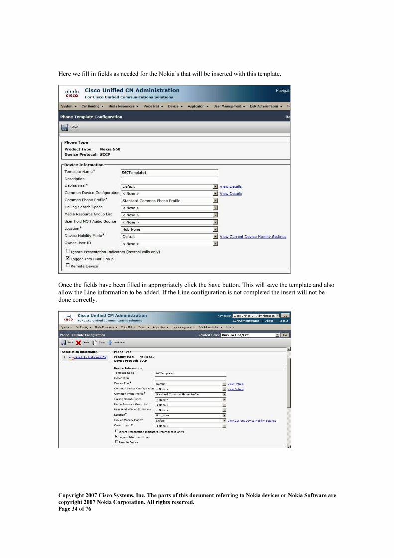
C o p y r i g h t 20 0 7 C i s c o S y s t e m s , I n c . T h e p a r t s o f t h i s d o c u m e n t r e f e r r i n g t o N o k i a d e v i c e s o r N o k i a S o f t w a r e a r e c o p y r i g h t 20 0 7 N o k i a C o r p o r a t i o n . A l l r i g h t s r e s e r v e d . P a g e 34 o f 76
H ere we f ill in f ields as needed f or the N okia’ s that will be inserted with this template.
O nce the f ields have been f illed in appropriately click the S ave button. This will save the template and also allow the L ine inf ormation to be added. If the L ine conf iguration is not completed the insert will not be done correctly.

C o p y r i g h t 20 0 7 C i s c o S y s t e m s , I n c . T h e p a r t s o f t h i s d o c u m e n t r e f e r r i n g t o N o k i a d e v i c e s o r N o k i a S o f t w a r e a r e c o p y r i g h t 20 0 7 N o k i a C o r p o r a t i o n . A l l r i g h t s r e s e r v e d . P a g e 35 o f 76
In the section below we show the template conf iguration f or the L ine. C lick S ave when you have f inished conf iguring the line.
This completes the Phone Template conf iguration.
1 . 8 . 1 . 2 . P h one F ile C onf ig ur ation A Phone File is used f or ex porting inf ormation about devices. In this case we are attempting to migrate as much of the current inf ormation f rom the currently registered devices as possible. B AT comes with a D ef ault and S tandard phone f ile template, but we are going to create one f rom scratch. B rowse to the B AT Phone File page by selecting B u l k A d m i n i s t r a t i o n > P h o n e s > P h o n e F i l e F o r m a t > C r e a t e F i l e F o r m a t and click the A d d Ne w button. The important part of this conf iguration is ensuring that we add all of the necessary f ields, which have been outlined below. Phone File Format C onf iguration order f or D e v i c e Fields
D evice N ame D escription AAR G roup C S S C ommon D evice C onf iguration D evice Pool D evice Presence G roup S ecurity Prof ile D evice S ubscribe C S S L ocation M L PP D omain D evice M obility M ode

C o p y r i g h t 20 0 7 C i s c o S y s t e m s , I n c . T h e p a r t s o f t h i s d o c u m e n t r e f e r r i n g t o N o k i a d e v i c e s o r N o k i a S o f t w a r e a r e c o p y r i g h t 20 0 7 N o k i a C o r p o r a t i o n . A l l r i g h t s r e s e r v e d . P a g e 36 o f 76
M edia R esource G roup L ist O wner User ID User H old Audio S ource Phone File Format C onf iguration order f or L i n e Fields
AAR G roup( L ine) D irectory N umber Alerting N ame Alerting N ame AS C II B usy Trigger AS C II D isplay Ex ternal Phone N umber M ask Forward All C S S Forward All C S S Activation Policy Forward All D estination Forward B usy Ex ternal C S S Forward B usy Ex ternal D estination Forward B usy Internal C S S Forward B usy Internal D estination Forward N o Answer Ex ternal C S S Forward N o Answer Ex ternal D estination Forward N o Answer Internal C S S Forward N o Answer Internal D estination Forward N o Answer R ing D uration Forward N o C overage Ex ternal C S S Forward N o C overage Ex ternal D estination Forward N o C overage Internal C S S Forward N o C overage Internal D estination Forward Unregistered Ex ternal C S S Forward Unregistered Ex ternal D estination Forward Unregistered Internal C S S Forward Unregistered Internal D estination Forward on C TI Failure C S S Forward on C TI Failure D estination H old R eversion N otif ication Interval H old R eversion R ing D uration L ine C S S L ine D escription L ine N etwork H old Audio S ource L ine Presence G roup L ine Tex t L abel L ine Tex t L abe AS C II L ine User H old Audio S ource M L PP C S S M L PP N o Answer R ing D uration M L PP Target M ax imum N umber of C alls M onitoring C alling S earch S pace Partition V oice M ail Prof ile C all Pickup G roup

C o p y r i g h t 20 0 7 C i s c o S y s t e m s , I n c . T h e p a r t s o f t h i s d o c u m e n t r e f e r r i n g t o N o k i a d e v i c e s o r N o k i a S o f t w a r e a r e c o p y r i g h t 20 0 7 N o k i a C o r p o r a t i o n . A l l r i g h t s r e s e r v e d . P a g e 37 o f 76
The phone f ile template is used when we ex port the phones f rom the database.
O nce the phone f ile template has been created, you will want to ex port your current phones. There are several types of N okia ES eries that could be in your database including E5 1, E6 0, E6 1, E6 1i, E6 5 , and E70’ s. Each device type is assigned a uniq ue base M AC address which we can use f or searching f or N okia devices, which otherwise will appear as C isco 79 X X phones. To search f or all possible N okia device types search f or the f ollowing base M AC addresses: E5 1 001adc E6 0 0015 de E6 1 0013f d E6 1i 0019 4f E6 5 0019 79 E70 0017b0
1 . 8 . 1 . 3 . E x por ting Nokia Dev ic es N ex t, browse to B A T > P h o n e s > E x p o r t P h o n e s > S p e c i f i c D e t a i l s . H ere we will perf orm the search using the criteria above. N otice in the f igure below that we are searching f or D evice N ame, C O N TAIN S , and O R . This will allow the search to f ind all potential N okia devices.

C o p y r i g h t 20 0 7 C i s c o S y s t e m s , I n c . T h e p a r t s o f t h i s d o c u m e n t r e f e r r i n g t o N o k i a d e v i c e s o r N o k i a S o f t w a r e a r e c o p y r i g h t 20 0 7 N o k i a C o r p o r a t i o n . A l l r i g h t s r e s e r v e d . P a g e 38 o f 76
B A T > P h o n e s > E x p o r t P h o n e s > S p e c i f i c D e t a i l s
Af ter you have searched and f ound the devices press Ne x t to ex port them. You will notice now that we can apply the Phone File Format created in earlier steps.
S ubmit your q uery to generate the phone f ile. This f ile will be used later f or importing the devices back into the database. To view the f ile that was created browse to B A T > U p l o a d / D o w n l o a d f i l e s . H ere we should f ind a .tx t f ile that can be downloaded locally and imported into Ex cel.

C o p y r i g h t 20 0 7 C i s c o S y s t e m s , I n c . T h e p a r t s o f t h i s d o c u m e n t r e f e r r i n g t o N o k i a d e v i c e s o r N o k i a S o f t w a r e a r e c o p y r i g h t 20 0 7 N o k i a C o r p o r a t i o n . A l l r i g h t s r e s e r v e d . P a g e 39 o f 76
N ex t we will open this f ile in Ex cel as a comma delimited f ile.
1 . 8 . 1 . 4 . U s i n g E x c e l t o M o d i f y P h o n e D a t a
O pen M S Ex cel and then open the .tx t f ile of ex ported data. W hen attempting to open the f ile M S Ex cel will recogniz e that this f ile could be a imported with delimiters and will prompt you how to open the f ile. You should open the f ile and select “ D e l i m i t e d ” and then select “ C o m m a ” f rom the delimiters as shown above. N ow that we have the phones successf ully ex ported and into a table f ormat f or importing we can modif y it appropriately. W e need to make the f ollowing changes:
D evice S ecurity Prof ile “ N okia S 6 0 – S tandard S C C P N on-S ecure Prof ile” M ax imum N umber of C alls f ield “ 3”
S ave this f ile as a .csv f ile type f or importing. B rowse back to B A T > U p l o a d / D o w n l o a d and upload the new .csv f ile.
1 . 8 . 1 . 5 . Deleting P h ones f r om th e Datab as e N ex t, we are going to delete the phones f rom the database using B AT. To delete phones browse to B A T > P h o n e s > D e l e t e P h o n e s > Q u e r y . W e will use the same search criteria that we used bef ore to delete the phones. N otice in the nex t f igure we have searched and f ound nine N okia devices in the database.

C o p y r i g h t 20 0 7 C i s c o S y s t e m s , I n c . T h e p a r t s o f t h i s d o c u m e n t r e f e r r i n g t o N o k i a d e v i c e s o r N o k i a S o f t w a r e a r e c o p y r i g h t 20 0 7 N o k i a C o r p o r a t i o n . A l l r i g h t s r e s e r v e d . P a g e 40 o f 76
Af ter running this job all 9 phones will be deleted. No t e : I f a u t o -r e g i s t r a t i o n h a s n o t be e n d i s a bl e d t h e S 60’ s m a y r e -r e g i s t e r ba c k t o C U C M a s 7 9 x x d e v i c e s .
1 . 8 . 1 . 6 . I mpor ting Dev ic es To import the phones we are going to use the uploaded .csv f ile and the template that was created earlier, both of which should be available f rom the drop downs. B rowse to B A T > U p l o a d / D o w n l o a d F i l e s to add the .csv f ile that was recently created, then click on the A d d Ne w button.

C o p y r i g h t 20 0 7 C i s c o S y s t e m s , I n c . T h e p a r t s o f t h i s d o c u m e n t r e f e r r i n g t o N o k i a d e v i c e s o r N o k i a S o f t w a r e a r e c o p y r i g h t 20 0 7 N o k i a C o r p o r a t i o n . A l l r i g h t s r e s e r v e d . P a g e 41 o f 76
N ex t, browse to B A T > P h o n e s > I n s e r t P h o n e s
O nce this job is run the phones will be added back to the database. If they are turned on and authenticated to the W L AN they may start registering back to C UC M .
1 . 8 . 1 . 7 . V alidating I ns er t B AT allows us to validate that the insert worked by viewing the details of the job. To view the job browse to B A T > J o b S c h e d u l e r and search f or the recently C ompleted job. C lick on the job ID to view if it was successf ul. If it f ailed, click on the L og File N ame to view the details of why it f ailed.
To verif y the phones are in the database you can perf orm a phone search, this time using D evice Type as C ontaining S 6 0. You should see the same number of phones as previously.

C o p y r i g h t 20 0 7 C i s c o S y s t e m s , I n c . T h e p a r t s o f t h i s d o c u m e n t r e f e r r i n g t o N o k i a d e v i c e s o r N o k i a S o f t w a r e a r e c o p y r i g h t 20 0 7 N o k i a C o r p o r a t i o n . A l l r i g h t s r e s e r v e d . P a g e 42 o f 76
The steps above should be used as a simplif ied ex ample. To learn more about B AT see the link below: http://www.cisco.com/en/US /partner/docs/voice_ ip_ comm/cucm/bat/6 _ 0_ 1/t03phtmp.html
1 . 8 . 2 . M i g r a t i o n S t e p s f o r C U C M V e r s i o n 5 . x The steps needed f or migrating device types in C UC M 5 .x are very similar to those in 6 .x , but they have been outlined below as well. Installation of the .cop f ile is the same in 5 .x as 6 .x , and the same device type ( N okia S 6 0) is added to the device list. In this ex ample we have 4 N okia E6 1’ s registered as 79 6 0’ s to a C UC M 5 .1( 3). O nce the .cop f ile has been installed we can begin migrating f rom the C isco device types to the S 6 0’ s. No t e : If IC C has been installed on the N okia dual-mode it will auto-register as a C isco 79 70 device.
1 . 8 . 2 . 1 . C U C M V e r s i o n 5 . x O v e r v i e w At a high level these are the steps needed to migrate f rom 79 6 0 / 79 70 device types to S 6 0 device type:
• C reate the S 6 0 phone template • C reate the N okia phone f ile • Ex port the current device data • M odif y the ex ported data f or insertion • D elete the current devices • Import the new devices data • V alidate the devices can now register
No t e : W hen perf orming the steps above it is necessary to temporarily turn of f auto-registration. If auto-registration is not turned of f your N okia devices may attempt to re-register as 79 6 0’ s or 79 70’ s bef ore you have re-inserted them.

C o p y r i g h t 20 0 7 C i s c o S y s t e m s , I n c . T h e p a r t s o f t h i s d o c u m e n t r e f e r r i n g t o N o k i a d e v i c e s o r N o k i a S o f t w a r e a r e c o p y r i g h t 20 0 7 N o k i a C o r p o r a t i o n . A l l r i g h t s r e s e r v e d . P a g e 43 o f 76
1 . 8 . 2 . 2 . C r e a t i n g t h e S 6 0 P h o n e T e m p l a t e B rowse to B u l k A d m i n i s t r a t i o n > P h o n e s > P h o n e T e m p l a t e f rom C UC M Administration screens and click on A d d Ne w . S elect No k i a S 60 as the device type and press Ne x t .
O nce the f ields have been f illed in appropriately click the S ave button. This will save the template and also allow the L ine inf ormation to be added. If the L ine conf iguration is not completed the insert will not be done correctly.

C o p y r i g h t 20 0 7 C i s c o S y s t e m s , I n c . T h e p a r t s o f t h i s d o c u m e n t r e f e r r i n g t o N o k i a d e v i c e s o r N o k i a S o f t w a r e a r e c o p y r i g h t 20 0 7 N o k i a C o r p o r a t i o n . A l l r i g h t s r e s e r v e d . P a g e 44 o f 76
1 . 8 . 2 . 3 . P h o n e F i l e C o n f i g u r a t i o n N ex t we are going to add the Phone File f or ex porting. To add this f ile browse to B u l k A d m i n i s t r a t i o n > P h o n e s > P h o n e F i l e F o r m a t > C r e a t e F i l e F o r m a t and click A d d Ne w . The D evice selected f ields order will be: D evice N ame D escription AAR C S S C S S D evice Pool M L PP D omain M edia R esource G roup L ist D evice S ubscribe C S S D evice Presence G oup O wner User ID User H old Audio S ource User ID The L ine selected f ields order will be: AAR G roup D irectory N umber Alerting N ame Alerting N ame AS C II B usy Trigger C all Pickup G roup Forward All C S S Forward All D estination Forward B usy Ex ternal C S S Forward B usy Ex ternal D estination Forward B usy Internal C S S Forward B usy Internal D estination Forward N o Answer Ex ternal C S S Forward N o Answer Ex ternal D estination Forward N o Answer Internal C S S Forward N o Answer Internal D estination Forward N o Answer R ing D uration Forward N o C overage Ex ternal C S S Forward N o C overage Ex ternal D estination Forward N o C overage Internal C S S Forward N o C overage Internal D estination Forward on C TI Failure C S S Forward on C TI Failure D estination L ine C S S L ine D escription L ine N etwork H old Audio S ource L ine Presence G roup L ine Tex t L abel L ine User H old Audio S ource M L PP C S S M L PP N o Answer R ing D uration M L PP Target M ax imum N umber of C alls

C o p y r i g h t 20 0 7 C i s c o S y s t e m s , I n c . T h e p a r t s o f t h i s d o c u m e n t r e f e r r i n g t o N o k i a d e v i c e s o r N o k i a S o f t w a r e a r e c o p y r i g h t 20 0 7 N o k i a C o r p o r a t i o n . A l l r i g h t s r e s e r v e d . P a g e 45 o f 76
Partition V oice M ail Prof ile M ax imum N umber of L ines = 2 C lick S a v e when f inished.
1 . 8 . 2 . 4 . E x p o r t i n g C u r r e n t P h o n e D a t a To ex port the inf ormation currently in the database, browse to B u l k A d m i n i s t r a t i o n > P h o n e s > E x p o r t P h o n e s > S p e c i f i c D e t a i l s . H ere you must choose the D evice Type and the Protocol f or ex porting. If you are dealing with clients on the IC C 1.0 version this will be 79 6 0; however, if you have IC C version 1.1 clients this will be 79 70. H ere too we will be using the base M AC address as our search criteria, which have been outlined below: E5 1 001adc E6 0 0015 de E6 1 0013f d E6 1i 0019 4f E6 5 0019 79 E70 0017b0 No t e : The UI of C UC M 5 .x does not allow f or multiple search criteria so you will need to perf orm individual searches f or each of the device types in your organiz ation. In our ex ample we have 4 E6 1’ s starting with the base M AC address 0013f d.
C lick the Ne x t button. N ow we ex port that data using the N okiaPhoneFile that was created in the previous steps.

C o p y r i g h t 20 0 7 C i s c o S y s t e m s , I n c . T h e p a r t s o f t h i s d o c u m e n t r e f e r r i n g t o N o k i a d e v i c e s o r N o k i a S o f t w a r e a r e c o p y r i g h t 20 0 7 N o k i a C o r p o r a t i o n . A l l r i g h t s r e s e r v e d . P a g e 46 o f 76
C lick on S u bm i t to run the job. B rowse to B u l k A d m i n i s t r a t i o n > J o b S c h e d u l e r to view the results of your ex port.
C lick on the J o b I d to view details of the results.

C o p y r i g h t 20 0 7 C i s c o S y s t e m s , I n c . T h e p a r t s o f t h i s d o c u m e n t r e f e r r i n g t o N o k i a d e v i c e s o r N o k i a S o f t w a r e a r e c o p y r i g h t 20 0 7 N o k i a C o r p o r a t i o n . A l l r i g h t s r e s e r v e d . P a g e 47 o f 76
N ow that we know the data has been successf ully ex ported we can download the f ile f or modif ication. To download the .tx t f ile browse to B u l k A d m i n i s t r a t i o n > U p l o a d / D o w n l o a d F i l e s , click on the check box nex t to the recently created f ile and select D o w n l o a d S e l e c t e d .
1 . 8 . 2 . 5 . U s i n g E x c e l t o M o d i f y P h o n e D a t a
S ave this f ile and open M S Ex cel. O nce Ex cel is open we are going to import this comma delimited f ile. In Ex cel choose F i l e > O p e n > ( No k i a E x p o r t .t x t f i l e ) . W hen opening the f ile you should be prompted with the Tex t Import W iz ard about how to open the f ile. C hoose D e l i m i t e d > Ne x t > C o m m a > Ne x t > F i n i s h .

C o p y r i g h t 20 0 7 C i s c o S y s t e m s , I n c . T h e p a r t s o f t h i s d o c u m e n t r e f e r r i n g t o N o k i a d e v i c e s o r N o k i a S o f t w a r e a r e c o p y r i g h t 20 0 7 N o k i a C o r p o r a t i o n . A l l r i g h t s r e s e r v e d . P a g e 48 o f 76
N ex t we are going to modif y the data in a couple ways as shown below: D evice N ame = R emove “ S EP” f rom the f ront of the M AC addresses M ax imum N umber of C alls = “ 3”

C o p y r i g h t 20 0 7 C i s c o S y s t e m s , I n c . T h e p a r t s o f t h i s d o c u m e n t r e f e r r i n g t o N o k i a d e v i c e s o r N o k i a S o f t w a r e a r e c o p y r i g h t 20 0 7 N o k i a C o r p o r a t i o n . A l l r i g h t s r e s e r v e d . P a g e 49 o f 76
B e sure to check your data f ile f or “ C isco 79 6 0” or “ C isco 79 70” and replace with “ N okia S 6 0”. N ow that this data has been updated we need to save this as a .csv f ile and upload it back to C UC M . No t e : W hen saving the f ile in Ex cel change the S ave As Type to “ C S V ( comma delimited) ( * .csv)”. If you get an error message indicating the f eatures may not be compatible click on Y e s .
1 . 8 . 2 . 6 . U p l o a d i n g D a t a f o r R e -I n s e r t i o n B ack in C UC M we need to upload this f ile. B rowse back to B u l k A d m i n i s t r a t i o n > U p l o a d / D o w n l o a d F i l e s . C lick on the A d d Ne w button to upload the f ile as below. File: ( newly created .csv f ile) S elect The Target: Phones S elect The Transaction Type: Insert Phones – S pecif ic D etails
1 . 8 . 2 . 7 . D e l e t i n g P h o n e s v i a B A T
N ow we can delete the current devices f rom the database. This can be done two ways. If you have a small number of phones you can simply search f or them f rom D e v i c e > P h o n e s and delete those that are known to be N okia’ s. If you have a large number you can use B AT. W e will outline the steps needed to use B AT f or deleting. First browse to B u l k A d m i n i s t r a t i o n > P h o n e s > D e l e t e P h o n e s > Q u e r y . H ere we will use the same search criteria as above ( base M AC addresses) to search f or the N okia devices.

C o p y r i g h t 20 0 7 C i s c o S y s t e m s , I n c . T h e p a r t s o f t h i s d o c u m e n t r e f e r r i n g t o N o k i a d e v i c e s o r N o k i a S o f t w a r e a r e c o p y r i g h t 20 0 7 N o k i a C o r p o r a t i o n . A l l r i g h t s r e s e r v e d . P a g e 50 o f 76
O nce the S u bm i t button is selected the phones will be deleted. No t e : If auto-registration has not been turned of f this is where it should be done. Your N okia dual-modes should unregister f or C UC M at this point.
1.8.2.8. R e -I m p o r t i n g No k i a D e v i c e D a t a N ex t we are going to import the phones back into the database. To insert the phones via B AT browse to B u l k A d m i n i s t r a t i o n > P h o n e s > I n s e r t P h o n e s . You should see the .csv f ile uploaded previously which should be tied to the Phone Template that was created earlier as well.

C o p y r i g h t 20 0 7 C i s c o S y s t e m s , I n c . T h e p a r t s o f t h i s d o c u m e n t r e f e r r i n g t o N o k i a d e v i c e s o r N o k i a S o f t w a r e a r e c o p y r i g h t 20 0 7 N o k i a C o r p o r a t i o n . A l l r i g h t s r e s e r v e d . P a g e 51 o f 76
C lick on S u bm i t to begin the process.
1 . 8 . 2 . 9 . V a l i d a t i n g D a t a I n s e r t i o n To review the status of the insert browse to B u l k A d m i n i s t r a t i o n > J o b S c h e d u l e r and f ind the J o b I d of the insert. The J o b R e s u l t S t a t u s should show S u c c e s s ; however, if it does not the L og File can be used to determine the reason f or f ailure.

C o p y r i g h t 20 0 7 C i s c o S y s t e m s , I n c . T h e p a r t s o f t h i s d o c u m e n t r e f e r r i n g t o N o k i a d e v i c e s o r N o k i a S o f t w a r e a r e c o p y r i g h t 20 0 7 N o k i a C o r p o r a t i o n . A l l r i g h t s r e s e r v e d . P a g e 52 o f 76
The f inal steps are to search f or the new N okia S 6 0 devices and attempt to re-register them to C UC M . H ere we have perf ormed a generic search to verif y the devices are indeed in the database.
1 . 8 . 3 . M i g r a t i n g S t e p s f o r C U C M V e r s i o n 4 . x Phones registered to C UC M version 4.x need to be migrated to the S 6 0 device type as well; however, the process is dif f erent due to dif f erences in the administration interf ace and B AT capabilities.
1 . 8 . 3 . 1 . C U C M V er s ion 4 . x O v er v iew Essentially the process is very similar as C UC M 6 .x , but we have provided a step-by-step ex ample to help administrators. Again, this can be done on a phone-by-phone basis, but B AT can be used to help speed the migration process. In our ex ample we have 8 N okia ES eries devices registered to C UC M , 2 E6 0’ s and 6 E6 1’ s, all registered using the 79 6 0 device type. To make the upgrade to 1.1 successf ul, we need to migrate these phones to the S 6 0 device type.
1 . 8 . 3 . 2 . C r eating C U C M 4 . x P h one F ile F or mat In 5 .x and higher C UC M allows users to customiz e the ex ported data via phone f ile f ormats. H owever, in 4.x and lower versions this was not the case. The only two options are All Phone D etails and D ef ault Phone. All Phone D etails can only be used when migrating all devices of a single type. For ex ample, if I wanted to ex port all inf o on 79 71’ s, this could be done and re-imported later without having to modif y the f ields. H owever, in this case we are changing device types so this cannot be done directly. Instead we are going to ex port the data we can using D ef ault Phone to populate the .csv f ile, and manually add the additional inf o needed to complete the insertion. To ex port the data browse to C o n f i g u r e > P h o n e s > E x p o r t P h o n e s and click Ne x t .

C o p y r i g h t 20 0 7 C i s c o S y s t e m s , I n c . T h e p a r t s o f t h i s d o c u m e n t r e f e r r i n g t o N o k i a d e v i c e s o r N o k i a S o f t w a r e a r e c o p y r i g h t 20 0 7 N o k i a C o r p o r a t i o n . A l l r i g h t s r e s e r v e d . P a g e 53 o f 76
B A T > C o n f i g u r e > P h o n e s > E x p o r t P h o n e s
1 . 8 . 3 . 3 . E x por ting C ur r ent P h one Data
To ex port all the phones we will search f or all 79 6 0’ s containing base M AC addresses. These base addresses are the f ollowing: E5 1 001adc E6 0 0015 de E6 1 0013f d E6 1i 0019 4f E6 5 0019 79 E70 0017b0 B elow is the output f rom our q uery ( ex ported f iles are sent to c:\B atFiles\Ex port\Phones): 1,0013FD 3D 1ED 9 ,Auto 5 041,,,5 041,,,,,,,,, 1,0013FD 3D D 6 08 ,Auto 5 038 ,,,5 038 ,,,,,,,,, 1,0013FD 408 2C 3,Auto 5 040,,,5 040,,,,,,,,, 1,0013FD 408 2D 0,Auto 5 039 ,,,5 039 ,,,,,,,,, 1,0013FD 408 2FA,Auto 5 037,,,5 037,,,,,,,,, 1,0013FD 408 310,Auto 5 036 ,,,5 036 ,,,,,,,,, 1,0015 D E3D 10E4,Auto 5 034,,,5 034,,,,,,,,, 1,0015 D E3F5 8 C E,Auto 5 035 ,,,5 035 ,,,,,,,,,

C o p y r i g h t 20 0 7 C i s c o S y s t e m s , I n c . T h e p a r t s o f t h i s d o c u m e n t r e f e r r i n g t o N o k i a d e v i c e s o r N o k i a S o f t w a r e a r e c o p y r i g h t 20 0 7 N o k i a C o r p o r a t i o n . A l l r i g h t s r e s e r v e d . P a g e 54 o f 76
B A T > C o n f i g u r e > P h o n e s > E x p o r t
The structure of the q uery can be seen in the picture above. B e sure to use “ O R ” rather than “ AN D ” while building the q uery or you may not get the results desired. Use the V iew Q uery R esult button to verif y the structure of your statement, and then click on the Ex port button. This f ile is saved in the C :\B atFiles\Ex port\Phones f older.
1 . 8 . 3 . 4 . C r eating S 6 0 P h one T emplate N ow that we have this data we are going to create a new S 6 0 device template. To create this template retrieve the B AT.x lt f ile f rom the server, located at c:\C iscoW ebs\B AT\Ex celTemplate\B AT.x lt. O nce downloaded, run the f ile by double-clicking on it.
B A T . x l t F i l e

C o p y r i g h t 20 0 7 C i s c o S y s t e m s , I n c . T h e p a r t s o f t h i s d o c u m e n t r e f e r r i n g t o N o k i a d e v i c e s o r N o k i a S o f t w a r e a r e c o p y r i g h t 20 0 7 N o k i a C o r p o r a t i o n . A l l r i g h t s r e s e r v e d . P a g e 55 o f 76
N ex t we are going to click on the C reate File Format button to customiz e our f ile. N otice that we have added most f ields; however, there are some listed at the device level that have been removed: At the D evice level: AAR C S S E.16 4 Phone L oad N ame N etwork L ocale User L ocale At the L ine level: D isplay Alerting N ame M ax imum number of calls L ine Tex t L abel No t e : B e sure that the B AT.x lt f ile and the Phone File created later are done in the same f ashion.
Press the C reate File Format button and press Yes to overwrite. Unf ortunately, at this point the process becomes manual. W e must copy out the inf o f rom the tex t f ile into the f ollowing f ields created: N umber of L ines M AC Address/D evice N ame D escription D irectory N umber Af ter populating the f ields click on the Ex port to B AT Format button. If the data has been entered correctly you will be asked where to save the f ile.

C o p y r i g h t 20 0 7 C i s c o S y s t e m s , I n c . T h e p a r t s o f t h i s d o c u m e n t r e f e r r i n g t o N o k i a d e v i c e s o r N o k i a S o f t w a r e a r e c o p y r i g h t 20 0 7 N o k i a C o r p o r a t i o n . A l l r i g h t s r e s e r v e d . P a g e 56 o f 76
The f ile that is created contains the f ormat needed f or inserting into the database, however, we need to remove the column headings that are inserted. O pen up the f ile and remove all data above the phone inf ormation, as shown below. R e m o v e t h e h e a d e r i n f o f r o m t h e B A T .x l t f i l e o u t p u t
This f ile should be uploaded to the C :\B atFiles\Phones\Insert f older on the C UC M server. At this point we can delete the phones f rom the database.
1 . 8 . 3 . 5 . Deleting Dev ic es v ia B A T D eleting the phones can be done via B AT as well. B rowse to C o n f i g u r e > D e l e t e P h o n e s f rom the B AT administration screen. W e will be searching the database f or only those devices f alling within N okia’ s M AC address ranges using the same q uery as above.

C o p y r i g h t 20 0 7 C i s c o S y s t e m s , I n c . T h e p a r t s o f t h i s d o c u m e n t r e f e r r i n g t o N o k i a d e v i c e s o r N o k i a S o f t w a r e a r e c o p y r i g h t 20 0 7 N o k i a C o r p o r a t i o n . A l l r i g h t s r e s e r v e d . P a g e 57 o f 76
B A T > C o n f i g u r e > D e l e t e P h o n e s
All N okia’ s registered as 79 6 0’ s should now be deleted f rom the database. If you do not have Auto-registration disabled they may being to re-register, which will cause the B AT insert to f ail and req uire the steps above to be run again. No t e : It is recommended that you turn O FF auto-registration during this process. If auto-registration is not turned of f your N okia devices may re-register bef ore the migration is complete.
1 . 8 . 3 . 6 . I ns er ting P h ones v ia B A T N ow we can begin to add the phones back to the database. As bef ore, our f irst step is to launch B AT and create the phone Template.

C o p y r i g h t 20 0 7 C i s c o S y s t e m s , I n c . T h e p a r t s o f t h i s d o c u m e n t r e f e r r i n g t o N o k i a d e v i c e s o r N o k i a S o f t w a r e a r e c o p y r i g h t 20 0 7 N o k i a C o r p o r a t i o n . A l l r i g h t s r e s e r v e d . P a g e 58 o f 76
B A T > C o n f i g u r e > P h o n e s > I n s e r t P h o n e s
S elect Insert Phones to begin the process. N otice that the process is broken down into 4 basic steps and that the application will step you through the process.
1 . 8 . 3 . 7 . C r eating S 6 0 P h one T emplate
To begin creating the phone template f or the S 6 0’ s click on S tep 1 and press N ex t. H ere we will conf igure both the template f or the device and the lines. B e sure to conf igure the L ine inf o as well.

C o p y r i g h t 20 0 7 C i s c o S y s t e m s , I n c . T h e p a r t s o f t h i s d o c u m e n t r e f e r r i n g t o N o k i a d e v i c e s o r N o k i a S o f t w a r e a r e c o p y r i g h t 20 0 7 N o k i a C o r p o r a t i o n . A l l r i g h t s r e s e r v e d . P a g e 59 o f 76
C lick B ack and move to S tep 2. N otice that the f irst part of the step is to create the C S V data f ile. This is the f ile created by the B AT.x lt f ile, which should have been copied to the C :\B atFiles\Phones\Import directory earlier.

C o p y r i g h t 20 0 7 C i s c o S y s t e m s , I n c . T h e p a r t s o f t h i s d o c u m e n t r e f e r r i n g t o N o k i a d e v i c e s o r N o k i a S o f t w a r e a r e c o p y r i g h t 20 0 7 N o k i a C o r p o r a t i o n . A l l r i g h t s r e s e r v e d . P a g e 60 o f 76
No t e : A l w a y s u s e t h e B A C K bu t t o n p r o v i d e d o n t h e w e b p a g e , n o t y o u r br o w s e r s .
1 . 8 . 3 . 8 . C r eating th e P h one F ile F or mat The nex t step is where we create the File Format. In this step we create a N okia File Format to add the appropriate f ields f or that device.

C o p y r i g h t 20 0 7 C i s c o S y s t e m s , I n c . T h e p a r t s o f t h i s d o c u m e n t r e f e r r i n g t o N o k i a d e v i c e s o r N o k i a S o f t w a r e a r e c o p y r i g h t 20 0 7 N o k i a C o r p o r a t i o n . A l l r i g h t s r e s e r v e d . P a g e 61 o f 76
This f ile should be created with the same options as the B AT.x lt f ile created earlier, with certain device and line level f ields removed. This creates the headers f or the data we will be associating in the nex t step. Press B ack and move to S tep 3of the C reate C S V data f ile page. H ere we are going to associate the data that was copied f rom the B AT.x lt program with the phone f ile that was just created.

C o p y r i g h t 20 0 7 C i s c o S y s t e m s , I n c . T h e p a r t s o f t h i s d o c u m e n t r e f e r r i n g t o N o k i a d e v i c e s o r N o k i a S o f t w a r e a r e c o p y r i g h t 20 0 7 N o k i a C o r p o r a t i o n . A l l r i g h t s r e s e r v e d . P a g e 62 o f 76
1 . 8 . 3 . 9 . V alidating th e B A T Data C lick the A d d button to update the data f ile with the headers. Af ter is done successf ully click B ack and move to the V alidation step.
This will validate that the data in the f ile is correct f or the header type. For ex ample, if you have an entry in the Partition f ield that is not present in the database, the validation will f ail.

C o p y r i g h t 20 0 7 C i s c o S y s t e m s , I n c . T h e p a r t s o f t h i s d o c u m e n t r e f e r r i n g t o N o k i a d e v i c e s o r N o k i a S o f t w a r e a r e c o p y r i g h t 20 0 7 N o k i a C o r p o r a t i o n . A l l r i g h t s r e s e r v e d . P a g e 63 o f 76
N otice that af ter clicking on the V alidate button the status has changed to “ V alidate C ompleted” and a log f ile is available to view. If validation f ails this log f ile can be usef ul f or troubleshooting.
1 . 8 . 3 . 1 0 . I ns er ting and V er if ying P h ones N ex t we move to S tep 4 of the process, inserting the phones. C lick the B ack button f rom the V alidation screen to move to this step.

C o p y r i g h t 20 0 7 C i s c o S y s t e m s , I n c . T h e p a r t s o f t h i s d o c u m e n t r e f e r r i n g t o N o k i a d e v i c e s o r N o k i a S o f t w a r e a r e c o p y r i g h t 20 0 7 N o k i a C o r p o r a t i o n . A l l r i g h t s r e s e r v e d . P a g e 64 o f 76
Inserting the phones works in much the same way as validating them ex cept that this time the database will be populated once f inished. No t e : If you have large numbers of devices to insert you may want to schedule time af ter peak hours to perf orm the operation. C hoose the same f ile and template as bef ore and click Insert to being the process.
Af ter completing you should get a message indicating that the insert was successf ul. If you got an error message, a log f ile will be created f or review.

C o p y r i g h t 20 0 7 C i s c o S y s t e m s , I n c . T h e p a r t s o f t h i s d o c u m e n t r e f e r r i n g t o N o k i a d e v i c e s o r N o k i a S o f t w a r e a r e c o p y r i g h t 20 0 7 N o k i a C o r p o r a t i o n . A l l r i g h t s r e s e r v e d . P a g e 65 o f 76
N ow that the phones have been reinserted we can go to the C UC M administration screen and search f or our phones. You should see them show up correctly as “ S 6 0” devices.

C o p y r i g h t 20 0 7 C i s c o S y s t e m s , I n c . T h e p a r t s o f t h i s d o c u m e n t r e f e r r i n g t o N o k i a d e v i c e s o r N o k i a S o f t w a r e a r e c o p y r i g h t 20 0 7 N o k i a C o r p o r a t i o n . A l l r i g h t s r e s e r v e d . P a g e 66 o f 76
1.9 . F u r t h e r R e a d i n g To review conf iguring Q oS on C isco access points ref er to the links below: For controller based conf igurations see: http://www.cisco.com/en/US /partner/products/ps6 36 6 /products_ conf iguration_ guide_ chapter09 18 6 a008 052d9 e9 .html For IO S based access points see: http://www.cisco.com/en/US /partner/products/hw/wireless/ps430/products_ conf iguration_ guide_ chapter0918 6 a008 06 06 d2f .html For f urther reading on W M M see the W i-Fi Alliance white paper here: http://www.wi-f i.org/f iles/uploaded_ f iles/wp_ 1_ W M M % 20Q oS % 20In% 20W i-Fi_ 9 -1-04.pdf To review C isco’ s C isco C ompatible Ex tensions ( C C X ) program see the link below: http://www.cisco.com/web/partners/pr46 /pr147/program_ additional_ inf ormation_ new_ release_ f eatures.html

C o p y r i g h t 20 0 7 C i s c o S y s t e m s , I n c . T h e p a r t s o f t h i s d o c u m e n t r e f e r r i n g t o N o k i a d e v i c e s o r N o k i a S o f t w a r e a r e c o p y r i g h t 20 0 7 N o k i a C o r p o r a t i o n . A l l r i g h t s r e s e r v e d . P a g e 67 o f 76
1.10 . Ap p e n d i x : A
This shows that B luetooth and 8 02.11b/g shares the same f req uency band. B luetooth ( B T) signal pattern in the 8 02.11b/g 2.4G H z spectrum of a typical B T earpiece.
B luetooth ( B T) signal pattern in the 8 02.11b/g 2.4G H z spectrum of a typical B T earpiece.

C o p y r i g h t 20 0 7 C i s c o S y s t e m s , I n c . T h e p a r t s o f t h i s d o c u m e n t r e f e r r i n g t o N o k i a d e v i c e s o r N o k i a S o f t w a r e a r e c o p y r i g h t 20 0 7 N o k i a C o r p o r a t i o n . A l l r i g h t s r e s e r v e d . P a g e 68 o f 76
The P I NK is the M ax H old line or the line that shows the max imum transmit power that was reached during the test. The Y E L L O W shows the max imum transmit power in the last sample period of ten seconds. The T U R Q U O I S shows the average transmit power over the period of the test. The v e r t i c a l d a s h e d lines separate the 3 non-overlapping 8 02.11b/g channels C h 1, C h 6, a n d C h 11. The charting is f rom 2.400G H z on the lef t to 2.5 00G H z on the right. From the right edge of the C h11 vertical blue line is part of the 8 02.11 spectrum used in Europe and J apan. This capture was done with an access point and clients conf igured f or the N orth American regulator domain. This graph shows that the B luetooth earpiece was easily transmitting outside of FC C regulations. N otice that the B T signal is very narrow. B T transmits data on a single M H z of f req uency. S tops the transmission, then moves to another f req uency in the 8 02.11 2.4G H z band then transmits data. This is continual repeated. The 8 02.11b and 8 02.11g signals are sent of a combined 22M H z of f req uency. The radio stays on that 22M H z of f req uency. That grouping of 22M H z is the ref erred to as the channel. The M ax H old line shows how strong the B T while in search mode. The signal level is above that of a 5 0mW ( 17dB m) O FD M 8 02.11g radio. A signal of this strength and duration will cause the N okia phone to drop V oW L AN call.
This chart shows an active call on channel 6 with a connected B T earpiece. N otice the dome shaped M ax H old line in the center of the chart. That is the typical spectrum representation of the 8 02.11b or 8 02.11g signal with the signal strongest right in the middle of the 22M H z of f req uencies that make up channel 6 . B T is sharp pointed signals shown in the channel 1 and channel 11 area of the spectrum. The earpiece has connected to the phone and is not in the high transmit power mode that it was in while searching f or the phone. At this time because the call was dropped when the earpiece was in search mode a new call was started. The call had poor voice q uality. The yellow line in side of the dome is the B T radio transmitting during the call on channel 6 . The chart was captured at the split second that B T was transmitting instead of the phone or access point transmitting.

C o p y r i g h t 20 0 7 C i s c o S y s t e m s , I n c . T h e p a r t s o f t h i s d o c u m e n t r e f e r r i n g t o N o k i a d e v i c e s o r N o k i a S o f t w a r e a r e c o p y r i g h t 20 0 7 N o k i a C o r p o r a t i o n . A l l r i g h t s r e s e r v e d . P a g e 69 o f 76
1.11. Ap p e n d i x : B
0
5
1 0
1 5
2 0
2 5
3 0
3 5
4 0
������ � �
� �
������ � �
�
������ � �
�
����� � �
��
����� � �
� �
����� � �
� �
������ � �
� �
������ � �
� �
������ � �
� �
������ � �
���
����� � �
���
����� � �
���
������ � �
� �
������ � �
� �
������ � �
� �
������ � �
�
����� � � �
����� � � �
�
������ � � �
�
����� � � �
�
I n P k t sI n R e t r yS T DM i nM a xA v gO u t P k t sO u t R e t r yS T DM i nM a xA v g
S ame call with B T earpiece.
0
5
1 0
1 5
2 0
2 5
3 0
3 5
4 0
21:43:35
21:43:36
21:43:36
21:43:37
21:43:37
21:43:38
21:43:38
21:43:39
21:43:39
21:43:40
21:43:40
21:43:41
21:43:41
21:43:42
21:43:42
21:43:43
21:43:43
21:43:44
21:43:44
21:43:45
21:43:45
21:43:46
21:43:46
21:43:47
21:43:47
21:43:48
21:43:48
I n P k t sI n R e t r yS T DM i nM a xA v gO u t P k t sO u t R e t r yS T DM i nM a xA v g
S ame call without B T earpiece.

C o p y r i g h t 20 0 7 C i s c o S y s t e m s , I n c . T h e p a r t s o f t h i s d o c u m e n t r e f e r r i n g t o N o k i a d e v i c e s o r N o k i a S o f t w a r e a r e c o p y r i g h t 20 0 7 N o k i a C o r p o r a t i o n . A l l r i g h t s r e s e r v e d . P a g e 70 o f 76
The ‘ In Pkts Avg’ line and the ‘ O ut Pkts Avg’ lines are very close to each other.
This is an Ethereal jitter analysis of three simultaneous phone calls each using a B T earpiece. All 3 calls were on the same AP and were calls to other N okia phones on this access point.

C o p y r i g h t 20 0 7 C i s c o S y s t e m s , I n c . T h e p a r t s o f t h i s d o c u m e n t r e f e r r i n g t o N o k i a d e v i c e s o r N o k i a S o f t w a r e a r e c o p y r i g h t 20 0 7 N o k i a C o r p o r a t i o n . A l l r i g h t s r e s e r v e d . P a g e 71 o f 76
1.12 . Ap p e n d i x : C.
The signal level is -46 dB m when the antenna of the phone is not obstructed.
W ith the hand over the antenna the signal strength was lowered to -5 3dB m. The signal level shown in this testing is very high. The AirM agnet capture tool was only 3 f eet away f rom the N okia phone. This shows that a signif icant dif f erence in signal strength can be caused by hand and head position relative to position of the phone. Also note that this test was done in a low multipath environment. M ultipath can also create a 4 to 6 dB swing in signal strength in a distance as little as one f oot. This series of tests was perf ormed on the Eseries models with similar results f or all.

C o p y r i g h t 20 0 7 C i s c o S y s t e m s , I n c . T h e p a r t s o f t h i s d o c u m e n t r e f e r r i n g t o N o k i a d e v i c e s o r N o k i a S o f t w a r e a r e c o p y r i g h t 20 0 7 N o k i a C o r p o r a t i o n . A l l r i g h t s r e s e r v e d . P a g e 72 o f 76
1.13 . Ap p e n d i x : D. A P a n d A n t e n n a P l a c e m e n t This section gives ex amples of both proper and improper placement of access points ( APs) and antennas. I m p r o p e r A P a n d A n t e n n a P l a c e m e n t Figure D -1 shows improper placement of an AP and antennas close to an I-beam, which creates distorted signal patterns. An R F null point is created by the crossing of signal waves, and multipath distortion is created when signal waves are ref lected. This placement results in very little coverage behind the AP and reduced signal q uality in f ront of the AP.
Figure D-1 I m p ro p er P l a c em en t o f A n t en n a s N ea r a n I -B ea m
Figure D -2 shows the signal propagation changes or distortions caused by an I-beam. The I-beam creates many ref lections f rom both received packets and transmitted packets. The ref lected signals result in very poor signal q uality because of null points and multipath interf erence. H owever, the signal strength is high because the AP antennas are so close to the I-beam.
Figure D- 2 S ign a l Dis t o rt io n s C a us ed b y P l a c in g t h e A n t en n a s T o o C l o s e t o a n I -B ea m

C o p y r i g h t 20 0 7 C i s c o S y s t e m s , I n c . T h e p a r t s o f t h i s d o c u m e n t r e f e r r i n g t o N o k i a d e v i c e s o r N o k i a S o f t w a r e a r e c o p y r i g h t 20 0 7 N o k i a C o r p o r a t i o n . A l l r i g h t s r e s e r v e d . P a g e 73 o f 76
The AP and antenna placement in Figure D -3 is better because it is away f rom the I-beams and there are f ewer ref lected signals, f ewer null points, and less multipath interf erence. This placement is still not perf ect because the Ethernet cable should not be coiled up so close to the antenna.
Figure D-3 A P a n d A n t en n a s M o un t ed o n a W a l l , A w a y f ro m I -B ea m s
Figure D -4 shows the signal propagation caused by the wall on which the AP is mounted.
Figure D-4 S ign a l R ef l ec t io n C a us ed b y a W a l l
The preceding ex amples also apply when placing APs and antennas in or near the ceiling in a standard enterprise environment. If there are metal air ducts, elevator shaf ts, or other physical barriers that can cause signal ref lection or multipath interf erence, C isco highly recommends that you move the antennas away f rom those barriers. In the case of the elevator, moving the antenna a f ew f eet away will help eliminate the signal ref lection and distortion. The same is true with air ducts in the ceiling. C o n c l u s i o n A survey conducted without sending and receiving packets is not suf f icient. The I-beam ex ample shows the creation of null points that can result f rom packets that have C R C errors. V oice packets with C R C errors will be missed packets that adversely af f ect voice q uality. In this ex ample, those packets could be above the noise f loor measured by a survey tool. Theref ore, it is very important that the site survey not only measures signal levels but also generates packets and then reports packet errors.

C o p y r i g h t 20 0 7 C i s c o S y s t e m s , I n c . T h e p a r t s o f t h i s d o c u m e n t r e f e r r i n g t o N o k i a d e v i c e s o r N o k i a S o f t w a r e a r e c o p y r i g h t 20 0 7 N o k i a C o r p o r a t i o n . A l l r i g h t s r e s e r v e d . P a g e 74 o f 76
1.14 . Ap p e n d i x F : Co n f i g u r i n g t h e N o k i a E -S e r i e s f o r E AP -P E AP
This is an ex ample of the basic steps needed to conf igure the N okia E-S eries with the C A C ertif icate provided and conf igure the appropriate settings f or the access-point using EAP-PEAP authentication.
1 . 1 4 . 1 . C o n v e r t i n g t h e C A c e r t i f i c a t e S ome certif icates may need a binary conversion bef ore they will be accepted by the N okia phones. If your certif icate does not work see the steps below.
1. The C A certif icate is the root certif icate installed on the AC S server. This certif icate is needed by the N okia f or their PEAP implementation. To convert the certif icate o p e n t h e c e r t i f i c a t e by d o u bl e -c l i c k i n g o n i t .
2. S elect the D e t a i l s tab. 3. Find the C o p y t o F i l e button and select it. 4. C lick the Ne x t button to begin. 5 . Ensure that D E R e n c o d e d bi n a r y X .509 is selected. 6 . Press the Ne x t button. 7. N ame the f ile and press Ne x t . 8 . C lick the F i n i s h button. 9 . You should get a message that the ex port was successf ul.
1 . 1 4 . 2 . I n s t a l l i n g t h e c e r t i f i c a t e o n t h e N o k i a E -S e r i e s O nce you have a properly f ormatted certif icate it needs to be installed on the N okia phone. There are several methods of accomplishing this, but one of the easiest is using the Inf rared ( IR ) port. The IR port on the N okia is at the bottom of the phone and it should be aligned with the IR port on your laptop. T u r n i n g o n t h e I R p o r t o f t h e N o k i a
1. Press the M e n u button. 2. Find the icon labeled C o n n e c t and select it. 3. S elect the I n f r a r e d icon and select it. You should get a message that the port is activated. 4. Position the IR port of the N okia ( at the bottom of the phone) in f ront of your laptop IR port.
T r a n s f e r r i n g f i l e s t o t h e N o k i a

C o p y r i g h t 20 0 7 C i s c o S y s t e m s , I n c . T h e p a r t s o f t h i s d o c u m e n t r e f e r r i n g t o N o k i a d e v i c e s o r N o k i a S o f t w a r e a r e c o p y r i g h t 20 0 7 N o k i a C o r p o r a t i o n . A l l r i g h t s r e s e r v e d . P a g e 75 o f 76
O nce you have the N okia aligned in f ront of your IR port you should see an icon that will allow you to transf er f iles. You need to f ind the certif icate f rom above and send it to the N okia. The f ile will be sent to the Inbox of the N okia. I n s t a l l i n g t h e c e r t i f i c a t e
1. There should be a N ew M essage indication on the N okia. C lick the S h o w option. 2. H ighlight the new message and open it. You should have the option to S a v e it. Press the S a v e
sof tkey. 3. If you get a message that the certif icate may not be secure select S a v e . 4. C lick the O K sof tkey. 5 . At the C ertif icate uses page put a check mark in both I n t e r n e t and O n l i n e c e r t . c h e c k i n g . 6 . Press the O K sof tkey. 7 . You should see a message that says C e r t i f i c a t e S a v e d .
1 . 1 4 . 3 . C o n f i g u r i n g t h e A c c e s s -P o i n t An access-point ( AP) must be conf igured to associate to the IT network. This AP can be used f or both web browsing and association to C isco C ommunications M anager. You should consult with your local IT staf f f or the S S ID that has the best coverage in your area. You can also check to see what S S ID your laptop is using by hovering over the C isco Aironet C lient Utility which will be in your system tray.
No t e : O n the N okia phone there are two ways to edit a f ield. You can either select the O p t i o n s sof tkey and go to c h a n g e , or you can use the t o g g l e bu t t o n and press it.
A c c e s s -P o i n t C o n f i g u r a t i o n
1. From the Idle screen press the M e n u button. 2. Find the T o o l s icon and select it. 3. Find the S e t t i n g s icon and select it. 4. S croll down to the C o n n e c t i o n heading and select it. 5 . S elect the A c c e s s P o i n t s heading. 6 . Find the O p t i o n s sof tkey and select this. H ighlight Ne w a c c e s s p o i n t and t o g g l e t o t h e r i g h t f or
more options. S elect U s e d e f a u l t s e t t i n g s . 7. C hange the C o n n e c t i o n n a m e to be a name of your pref erence. 8 . S croll to D a t a be a r e r and change it to W i r e l e s s L A N. 9 . S croll to W L A N n e t w . Na m e , change to E n t e r m a n u a l l y and enter y o u r S S I D as the W L AN
network name. 10. S croll to Ne t w o r k s t a t u s and select H i d d e n , unless you are broadcasting you S S ID . 11. S croll to W L A N n e t w . M o d e and make sure it is set as I n f r a s t r u c t u r e . 12. S croll to W L A N s e c u r i t y m o d e and change it to 802.1x .
1 . 1 4 . 4 . C o n f i g u r i n g f o r E A P -P E A P
13. S croll to W L A N s e c u r i t y s e t t . Ensure that W P A is set to E A P . S croll down to E A P p l u g -i n s e t t i n g s and select it to change the settings.

C o p y r i g h t 20 0 7 C i s c o S y s t e m s , I n c . T h e p a r t s o f t h i s d o c u m e n t r e f e r r i n g t o N o k i a d e v i c e s o r N o k i a S o f t w a r e a r e c o p y r i g h t 20 0 7 N o k i a C o r p o r a t i o n . A l l r i g h t s r e s e r v e d . P a g e 76 o f 76
Under the EAP plug-in settings we need to do three things. First, make sure that E A P -P E A P is enabled, move EAP-PEAP to the h i g h e s t p r i o r i t y , and set all other EAP types to d i s a bl e d .
14. To enable EAP-PEAP scroll down and highlight it, then press the O p t i o n s sof tkey. C lick the E n a bl e selection.
15 . To raise the priority of EAP-PEAP highlight it and press the O p t i o n s sof key, then select R a i s e p r i o r i t y . D o this until EAP-PEAP is in the number one position at the top.
16 . To disable the other EAP types highlight them, press O p t i o n s , and select D i s a bl e . 17. W hen you are done with the steps above press the O p t i o n s sof tkey and select C o n f i g u r e .
C o n f i g u r i n g t h e E A P -P E A P s e t t i n g s
No t e : The nex t section is where most of the EAP conf iguration is done. The f ields m u s t be done ex actly as indicated below.
18 . L eave the U s e r c e r t i f i c a t e f ield as ( n o t d e f i n e d ) . 19 . S croll to C A c e r t i f i c a t e and select it. You should f ind the certif icate that was saved in steps 1-7
f rom above. If you do not see your certif icate f rom the list it was not saved in the proper f ormat. 20. S croll to U s e r n a m e i n u s e and change it to U s e r -c o n f i g u r e d . 21. S croll to U s e r n a m e and select it. H ere you will use the f ollowing f ormat f or username if using
Active D irectory: < u s e r n a m e > @ d o m a i n .c o m . ( case sensitive only – use up arrow key to change case)
22. Press the O K button when f inished. 23. S croll to R e a l m i n u s e and change to U s e r -c o n f i g u r e d . H ere we will use the f ollowing f ormat:
d i r e c t o r y .c o m . ( C ase sensitive - use up arrow key to change case). 24. S croll down to A l l o w P E A P v 2 and change it to No . The only PEAP version that should be
allowed is PEAPv0. 25 . Use the S croll button to go to the E A P tab by pushing to the R i g h t . 26 . H ere we want to do two things: move E A P -M S C H A P v 2 to the highest priority, and d i s a bl e all
other options. R ef erence steps 14 – 16 f or instructions on how. 27. O nce EAP-M S C H APv2 is enabled and at the top of the list in the number one position, highlight
E A P -M S C H A P v 2 and press the O p t i o n s sof tkey. S elect C o n f i g u r e . C o n f i g u r i n g E A P -M S C H A P v 2
28 . S elect the U s e r n a m e option and enter your C i s c o U s e r I D ( L ower case only - use up arrow key to change case.).
29 . Prompt password should say No . 30. Enter your Active D irectory password. 31. Press the B a c k sof key when f inished.
C o n f i g u r i n g t h e E A P C i p h e r
32. O nce you have f inished the EAP-M S C H APv2 settings and pressed back, use the scroll button to press R i g h t and f ind the C i p h e r tab.
33. Ensure that A L L cipher options are enabled. There are two that are not enabled by def ault at the very bottom of the list: R S A, R C 4, M D 5 and R S A, R C 4, S H A – E n a bl e t h e s e .
34. Press the B a c k button when f inished. C ontinue pressing the B a c k button until you are back at the A c c e s s P o i n t s list. You should now see your access-point in the list.
To test your conf iguration you can open a web browser and point it to the new access-point.