NMT Facility Guidelines, 2014 - Bicycle Infrastructure Manuals
199
-
Upload
khangminh22 -
Category
Documents
-
view
0 -
download
0
Transcript of NMT Facility Guidelines, 2014 - Bicycle Infrastructure Manuals

S
NMT Facility Guidelines, 2014
For: Department of Transport
By: SMEC/UCT
Date: December 2014
Authors:
Dr Marianne Vanderschuren
Ms Sekadi Phayane
Mr Arthur Taute
Dr Hubrecht Ribbens
Mr Neville Dingle
Mr Kuben Pillay
Dr Mark Zuidgeest
Ms Sazi Enicker
Ms Jennifer Baufeldt
Ms Gail Jennings


Foreword by the Minister of Transport Dipuo Peters, MP
In 1987 and 1993, the Department published manuals to address the needs of cyclists and pedestrians only. These manuals, however, became out-dated due to new technologies and developments in the provision of facilities for non-motorised transport (NMT). The Department decided to evaluate, review and combine these manuals into a practical and user-friendly “Pedestrian and Bicycle Facility Guidelines Manual” of 2003.
Since 2003, there has been a significant legislative and policy developments affecting the transport landscape, and it is imperative that the guideline be updated to be in line with these changes. The Department’s view is that NMT Facility Guideline Manual be aligned with the new technological development so that it effectively addresses the needs of all road users.
The new NMT Facility Guideline Manual is therefore a revision and update of the existing Pedestrian and Bicycle Facility Guidelines (2003) which does not seek to set out a new policy, but give effect to existing policy by providing guidance for a more balanced approach to the design of towns and cities for the benefit of NMT users.
The main purpose of the new NMT Guideline is to provide guidance on the planning and design for safe pedestrian, bicycle, and other alternative low carbon modes of transport, both across and alongside roads and streets. Furthermore, the guideline will strengthen the provision of well-designed bicycle and pedestrian facilities and infrastructure to improve the physical environment and safety of NMT users.
The Guideline is aligned to the Road Traffic Act of 1996, the National Land Transport Act of 2009, the Moving South Africa Action Agenda (2020), Municipal Integrated Development Plan (IDP), Shova Kalula Rollout Plan (2007), and the Road Infrastructure Strategic Framework of 2006 (RIFSA). The new manual is also linked to other planning tools and standards such as the South African and SADC Road Traffic Signs Manual, the South African Road Safety Manual and numerous other standards and guidelines.
In addition, the universal design/access (UD or UA), which involves the provision of infrastructure and services that cater for a wide range of people living with disabilities, is also gaining focus and momentum. This philosophy is adequately addressed in the NMT Facility Guideline Manual.
FINAL DRAFT: NON‐MOTORISED TRANSPORT FACILITY GUIDELINES (2014)
(i)
TABLE OF CONTENTS
Page No
1. INTRODUCTION ....................................................................................................... 1 1.1 Motivation for the NMT Guidelines Update .............................................................................. 1
South Africa’s Mobility Status-Quo ........................................................................... 2 1.1.1 South Africa’s Road Safety Challenge ..................................................................... 3 1.1.2 Effects of Speed on Pedestrian Facilities ................................................................. 4 1.1.3 History of South African Planning ............................................................................ 4 1.1.4
1.2 Methodology Undertaken......................................................................................................... 5 1.3 How to Use the NMT Facility Guidelines ................................................................................. 6
2. POLICY AND LEGISLATION ................................................................................... 8 2.1 Policy Framework .................................................................................................................... 8
White Paper on National Transport Policy, 1996 ..................................................... 8 2.1.1 National Land Transport Strategic Framework, 2006 (NLTSF) ............................... 8 2.1.2 Public Transport Strategy and Action Plan, 2007 .................................................... 9 2.1.3 Rural Transport Strategy for South Africa, 2007 ...................................................... 9 2.1.4 Department of Transport Draft Policy Document on NMT ....................................... 9 2.1.5
2.2 Legislative Framework ........................................................................................................... 10 National Land Transport Act 5 of 2009 (NLTA) ...................................................... 10 2.2.1 The National Road Traffic Act 93 of 1996 (NRTA) ................................................. 12 2.2.2 National Road Traffic Regulations, 2000 (NRT Regulations) ................................ 12 2.2.3 Administrative Adjudication of Road Traffic Offences Act 46 of 1998 (AARTO Act)2.2.4
................................................................................................................................ 14 National Building Regulations and Building Standards Act 103 of 1977 ............... 14 2.2.5 South African National Roads Agency Limited and National Roads Act 7 of 1998 2.2.6
(SANRAL Act) and Other Roads Legislation .......................................................... 15 National Environmental Management Act 107 of 1998 (NEMA) ............................ 16 2.2.7 National Heritage Resources Act 25 of 1999 ......................................................... 16 2.2.8 Promotion of Administrative Justice Act 3 of 2000 (PAJA) .................................... 16 2.2.9 Legal Requirements for Animal-Drawn Vehicles ................................................... 16 2.2.10 South Africa’s Universal Access Regulations ........................................................ 17 2.2.11 Municipal By-Laws ................................................................................................. 17 2.2.12
2.3 Connecting Policy and Practice ............................................................................................. 19 2.4 Implementation Processes .................................................................................................... 19
3. PLANNING ............................................................................................................. 20 3.1 NMT Detail Planning (Project Level Assessments) ............................................................... 20
Greenfield Planning ................................................................................................ 20 3.1.1 NMT Planning within Developed Areas .................................................................. 21 3.1.2
3.2 Pedestrian Route Network Planning ...................................................................................... 22 Desire Line Route Assessments ............................................................................ 22 3.2.1 Base Map to Assess Land Use and Origin and Destinations ................................ 22 3.2.2 Impact of Transport Environment on Pedestrian Behaviour .................................. 23 3.2.3 Tested and Refined Network Based on User Requirements ................................. 24 3.2.4
3.3 Cycling Route Network Planning ........................................................................................... 27 Inventory ................................................................................................................. 27 3.3.1 Determining Needs of Cyclists ............................................................................... 27 3.3.2 Mapping Existing Facilities, Routes, Bicycle-Related Accidents and Bicycle 3.3.3
Volumes.................................................................................................................. 28 Mapping Main Infrastructure Barriers and Identifying Missing Connections .......... 29 3.3.4
FINAL DRAFT: NON‐MOTORISED TRANSPORT FACILITY GUIDELINES (2014)
(ii)
Assessing and Understanding Potential Demand .................................................. 29 3.3.5 Prioritising Bicycle Network Structure including Route Components ..................... 29 3.3.6 Developing Sketch Plan Bicycle Network Structure ............................................... 30 3.3.7
3.4 Inventory and Condition Assessment .................................................................................... 31 Condition Assessments .......................................................................................... 31 3.4.1
3.5 Determining the Extent of Improvements Required .............................................................. 33 Prioritisation ............................................................................................................ 33 3.5.1 Programmes ........................................................................................................... 34 3.5.2 Viability ................................................................................................................... 35 3.5.3
3.6 Developing Design Concepts ................................................................................................ 36 Functional Classification ......................................................................................... 36 3.6.1 Land Use ................................................................................................................ 37 3.6.2
3.7 Sustainability .......................................................................................................................... 39 Social Progress and Economic Development ........................................................ 39 3.7.1 Environmental Progress ......................................................................................... 39 3.7.2
4. NMT ROAD DESIGN DETAILS .............................................................................. 40 4.1 Introduction ............................................................................................................................ 40 4.2 Design Criteria for Universal Access ..................................................................................... 40
Sidewalk Related Universal Access Requirements ............................................... 42 4.2.1 Universal Design Requirements for Bicycle Facilities ............................................ 45 4.2.2 Separation .............................................................................................................. 46 4.2.3
4.3 General Design Parameters and Criteria .............................................................................. 47 4.4 Drainage Designs .................................................................................................................. 50 4.5 NMT Only Facilities (Exclusive) ............................................................................................. 51 4.6 NMT along Roads .................................................................................................................. 53
Highways with Controlled Access .......................................................................... 54 4.6.1 High Speed Highways ............................................................................................ 55 4.6.2 Kerbed Arterials ...................................................................................................... 57 4.6.3 Urban Distributors and Collectors (60 km/h) .......................................................... 59 4.6.4 Access Roads ........................................................................................................ 61 4.6.5 Bicycle Priority Streets ........................................................................................... 63 4.6.6
4.7 Bridges and Underpasses ..................................................................................................... 64 Principles of Bridge and Underpass Location and Design ..................................... 64 4.7.1 Bridges ................................................................................................................... 66 4.7.2 Underpasses .......................................................................................................... 68 4.7.3 NMT River Bridges in Rural Areas ......................................................................... 70 4.8.1
4.9 Intersection Design ................................................................................................................ 72 4.10 Pedestrian Crossing Facilities ............................................................................................... 73
Pedestrian Facilities at Controlled Midblock Crossing ........................................... 75 4.10.1 Pedestrian Facilities at Uncontrolled Intersections ................................................ 77 4.10.1
4.11 Bicycle Crossing Facilities ..................................................................................................... 79 Bicycle Facilities at Controlled Intersections .......................................................... 79 4.11.1 Bicycle Facilities at Uncontrolled intersections ...................................................... 83 4.11.2 Bicycle Priority Intersection .................................................................................... 85 4.11.1
4.12 Railway Crossing Facilities .................................................................................................... 87
5. SAFETY AND GUIDANCE ..................................................................................... 89 5.1 Signage .................................................................................................................................. 89 5.2 Road Markings ....................................................................................................................... 91 5.3 Way Finding ........................................................................................................................... 92 5.4 Lighting .................................................................................................................................. 93 5.5 Personal Security ................................................................................................................... 93
FINAL DRAFT: NON‐MOTORISED TRANSPORT FACILITY GUIDELINES (2014)
(iii)
5.6 Traffic Calming ....................................................................................................................... 94 Speed Humps ......................................................................................................... 95 5.6.1 Speed Tables ......................................................................................................... 97 5.6.2 Rumble Strips ......................................................................................................... 99 5.6.3 Roundabouts and Traffic Circles .......................................................................... 100 5.6.4 Chicanes .............................................................................................................. 102 5.6.5 Neck Downs ......................................................................................................... 104 5.6.6 Chokers ................................................................................................................ 104 5.6.7 Half Closure .......................................................................................................... 106 5.6.8
5.7 Drop Kerbs and Tactile Paving ............................................................................................ 108 Tactile Paving Principles ...................................................................................... 108 5.7.1 Drop Kerbs or Kerb Cuts at Locations without Traffic Signals ............................. 111 5.7.2 Angled Drop Kerb Treatment ............................................................................... 113 5.7.3 Drop Kerb at Signalised Intersections .................................................................. 113 5.7.4
5.8 Construction / Development Sites ....................................................................................... 115 Principles of Design .............................................................................................. 115 5.8.1
6. END OF TRIP FACILITIES ................................................................................... 118 6.1 Public Transport Hubs ......................................................................................................... 118
118 NMT Design at Off-Street Interchanges ............................................................... 119 6.1.1 NMT Design at On-Street Facilities ...................................................................... 120 6.1.2 Median Public Transport Stations ........................................................................ 124 6.1.3
6.2 Bicycle Parking .................................................................................................................... 126 Principles of Bicycle Parking Location ................................................................. 126 6.2.1
6.3 NMT Facilities at Schools .................................................................................................... 129 School Precinct Access ........................................................................................ 129 6.3.1
6.4 NMT Facilities at Rural Schools .......................................................................................... 131 6.5 Animal-Drawn Vehicles ........................................................................................................ 132
Geometric Design Elements of Roads ................................................................. 134 6.5.1 ADV Parking Areas in Towns ............................................................................... 137 6.5.2
7. CAPACITY ............................................................................................................ 138 7.1 Walkway Capacity ............................................................................................................... 138 7.2 Waiting Areas ...................................................................................................................... 140 7.3 Bicycle Congestion .............................................................................................................. 141
8. NMT PAVEMENT DESIGN ................................................................................... 143 8.1 Introduction .......................................................................................................................... 143 8.2 Clay and Concrete Brick Pavers .......................................................................................... 145 8.3 Cobbles and Natural Stone.................................................................................................. 145 8.4 Concrete Slabs .................................................................................................................... 145
Cast-in-Situ Concrete Slabs ................................................................................. 145 8.4.1 Cast Concrete Slabs with Patterns ...................................................................... 146 8.4.2
8.5 Bituminous Surfacings ......................................................................................................... 146 8.6 Resume................................................................................................................................ 147
9. MAINTENANCE .................................................................................................... 148 9.1 Introduction .......................................................................................................................... 148 9.2 Management Systems ......................................................................................................... 148 9.3 NMT Inventory ..................................................................................................................... 148 9.4 Condition Monitoring ............................................................................................................ 152 9.5 Usage ................................................................................................................................... 153 9.6 Stakeholder Requirements .................................................................................................. 153
FINAL DRAFT: NON‐MOTORISED TRANSPORT FACILITY GUIDELINES (2014)
(iv)
9.7 Situational Analysis .............................................................................................................. 153 General Statistics ................................................................................................. 153 9.7.1 NMT Condition and Service Levels ...................................................................... 154 9.7.2 NMT Safety .......................................................................................................... 154 9.7.3
9.8 Maintenance Needs ............................................................................................................. 155 9.9 Maintenance Activities ......................................................................................................... 156
10. OPERATIONS ...................................................................................................... 159 10.1 Safety ................................................................................................................................... 159 10.2 Training of Drivers and Pedestrians .................................................................................... 159 10.3 Reflective Clothing ............................................................................................................... 159 10.4 Rural School Cycling Programme ....................................................................................... 159 10.5 Cycle Rental Schemes ........................................................................................................ 160
South African Bicycle Rental Schemes ................................................................ 160 10.5.1 Key Aspects When Implementing a Bicycle Rental Scheme ............................... 161 10.5.2
11. REFERENCES...................................................................................................... 163
FINAL DRAFT: NON‐MOTORISED TRANSPORT FACILITY GUIDELINES (2014)
(v)
FIGURES
Figure 1-1: New Way of Street Design (DTTS, Ireland 2013) ................................................................ 1
Figure 1-2: Road Fatalities per 100,000 Inhabitants in Various Cities ................................................... 3
Figure 1-3: Pedestrian Accident Severity ................................................................................................ 4
Figure 1-4: Project Process ..................................................................................................................... 5
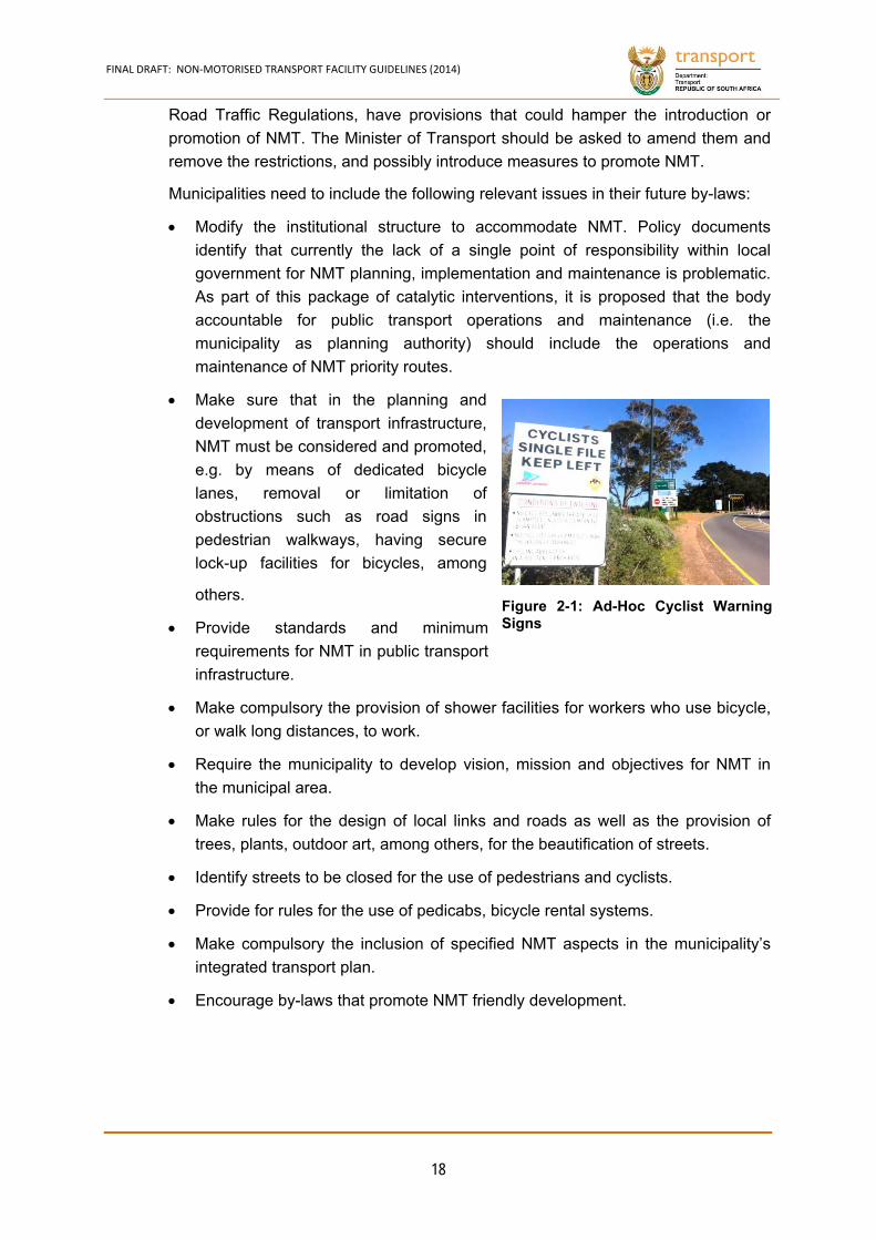
Figure 2-1: Ad-Hoc Cyclist Warning Signs ............................................................................................ 18
Figure 3-1: Example of Base Map Linking Origins with Destinations, Source: SMEC ......................... 23
Figure 3-2: Elastic Thread Method Applied ........................................................................................... 30
Figure 3-3: Example of NMT Condition Map ......................................................................................... 32
Figure 3-4: Road Classification for Mobility/ Accessibility ..................................................................... 36
Figure 4-1: Space Requirements for NMT Users .................................................................................. 42
Figure 4-2: Requirements for NMT Users with Special Needs, (DoT UK, Inclusive Mobility (2002) .... 44
Figure 4-3: Space Requirements for Bicycle Users .............................................................................. 45
Figure 4-4: Space Requirements for Extraordinary Bicycle Users ....................................................... 45
Figure 4-5: Acceptable gradients for cycling (Austroad, 1993) ............................................................. 48
Figure 4-6: Water Ponding Along a Sidewalk ....................................................................................... 50
Figure 4-7: Good Drainage Along a Sidewalk ...................................................................................... 50
Figure 4-8: NMT Underpass Using River Bridge .................................................................................. 51
Figure 4-9: Exclusive Bike Trail at the Cradle of Humankind ............................................................... 51
Figure 4-10: Pedestrian and Bicycle Facility Adjacent to and Below a Highway Section (Seoul) ........ 54
Figure 4-11: Walkway Suspended on Highway Bridge (Vienna) .......................................................... 54
Figure 4-12: Walkway below Highway Bridge (Bratislava) ................................................................... 54
Figure 4-13: Walkway behind Guardrail with Light Barrier on High Fill ................................................ 55
Figure 4-14: Unprotected Walkway too Close to the Road is Unacceptable ........................................ 55
Figure 4-15: Walkway with Kerbed Barrier ........................................................................................... 55
Figure 4-16: Combined Bike and Pedestrian Lanes (Vienna) .............................................................. 57
Figure 4-17: Bike and Motorbike Lane Behind Barrier (Huangzhou) .................................................... 57
Figure 4-18: Bicycle and Pedestrian Lane (Caiscais) ........................................................................... 57
Figure 4-19: Urban Collector with Bicycle Lane (Portland USA) .......................................................... 59
Figure 4-20: Road Diet Example ........................................................................................................... 59
Figure 4-21: Access Road (Netherlands) .............................................................................................. 61
Figure 4-22: Access Road (Miami) ....................................................................................................... 61
Figure 4-23: Access Road (Soshanguve, City of Tshwane) ................................................................. 61
Figure 4-24: Bicycle Priority Street (London) ........................................................................................ 63
Figure 4-25: Bicycle Lane Under Bridge (Salzburg) ............................................................................. 66
Figure 4-26: NMT Bridge (Lelystad) ...................................................................................................... 66
Figure 4-27: Wide, Well-Lit Underpass (Seoul) .................................................................................... 68
Figure 4-28: NMT Underpass (Lelystad) ............................................................................................... 68
Figure 4-29: Suspension Bridge Across the Esiphongweni River in KZN ............................................ 70
Figure 4-30: Wading through Rivers due to Lack of Bridges ................................................................ 70
Figure 4-31: Conflict Points .................................................................................................................. 72
Figure 4-32: Tight Radii Limits Desire Lines and Sight Distances ........................................................ 73
Figure 4-33: Large Radii Increases Desire Lines and Sight Distances ................................................ 73
Figure 4-34: Tactile Paving at Dropped Midblock Facility ..................................................................... 75
Figure 4-35: Midblock Crossing Detail .................................................................................................. 75
Figure 4-36: Radii Creates Safety Risk ................................................................................................. 81
Figure 4-37: Raised Bicycle Priority Intersection (Lelystad) ................................................................. 85

FINAL DRAFT: NON‐MOTORISED TRANSPORT FACILITY GUIDELINES (2014)
(vi)
Figure 4-38: Warning at Rail Crossing .................................................................................................. 87
Figure 4-39: Example of Delineation Requirements ............................................................................. 87
Figure 5-1: RTM 9 Lines Delineating Bicycle Lane ............................................................................... 91
Figure 5-2: RM 1 Line Marking Highlighting Obstruction ...................................................................... 91
Figure 5-3: Colour Choices for Pictograms and NMT Road Signs ....................................................... 93
Figure 5-4: Example of a Good Speed Table ....................................................................................... 97
Figure 5-5: Drainage and Access for People in Wheelchairs Provided (Cape Town) .......................... 97
Figure 5-6: Badly Implemented Speed Tables can Cause Wheelchairs to Hit the Street Surface and Tip Over ......................................................................................................................................... 97
Figure 5-7: Example of a Choker ........................................................................................................ 104
Figure 5-8: Guidance and Directional Tactile Pavers ......................................................................... 108
Figure 6-1: Interchanges Result in Better Flow of People and Traffic ................................................ 118
Figure 6-2: Pedestrians Remain Level throughout the Interchange ................................................... 119
Figure 6-3: Intermediate Bus Stop ...................................................................................................... 120
Figure 6-4: Bus Access Gap Reduction .............................................................................................. 121
Figure 8-1: Deformation at Joints in Concrete Slabs .......................................................................... 145
Figure 8-2: Wheelchair and Scooter Wheel Challenges ..................................................................... 146
Figure 9-1: High Sidewalk Ambiance .................................................................................................. 154
Figure 9-2: Push Cart Stuck in Small Surface Defect ......................................................................... 158
Figure 9-3: Wheelchair Punctured by Loose Stones .......................................................................... 158
Figure 9-4: Tree Boles Protected with Asphalt (Sydney) .................................................................... 158
Figure 10-1: Bicycle Lockup at Schools .............................................................................................. 159
Figure 10-2: Role of Bicycle Rental Schemes .................................................................................... 160
Figure 10-3: Advertising on a Public Transport Facility ...................................................................... 162
FINAL DRAFT: NON‐MOTORISED TRANSPORT FACILITY GUIDELINES (2014)
(vii)
TABLES
Table 1-1 Mode of Transport for Workers, by Provinces, 2013 2
Table 3-1: Different User Types for Consideration 28
Table 3-2: Minimum Daily Usage to Include in Inventory 31
Table 3-3: Examples of NMT Programmes 34
Table 3-4: South African Road Classification 37
Table 3-5: NMT Concept Designs 38
Table 4-1: NMT Degrees of Separation 46
Table 4-2: Mode Separation Requirements 46
Table 4-3: Design Criteria for NMT Facilities 47
Table 4-4: Minimum Distances Between Crossings/Road Elements 73
Table 5-1: Line Markings for NMT 91
Table 5-2: Type of Information Aids 92
Table 5-3: Traffic Calming Types, Application and Impacts 94
Table 5-4: Measures to Reduce Speed 95
Table 7-1: LOS Criteria for Walkways and Sidewalks 138
Table 7-2: LOS Criteria for Pedestrian Queuing Areas 140
Table 8-1: Summary of Surface Characteristics 147
Table 9-1: NMT Asset Condition and Functional Ratings 152
Table 9-2: Maintenance Categories 155
Table 9-3: Indicative Maintenance Needs 156
Table 9-4: SANRAL RRM Manual Content 157
FINAL DRAFT: NON‐MOTORISED TRANSPORT FACILITY GUIDELINES (2014)
(viii)
ABBREVIATIONS
AARTO Act Administrative Adjudication of Road Traffic Offences Act 46 of 1998
ADV Animal-drawn vehicle
BRT Bus rapid transit
DoT National Department of Transport
IDP Integrated development plan
ITP Integrated transport plan
MEC Member of the Executive Council responsible for public transport in the province concerned, or, where applicable, the MEC of another province responsible for public transport
NEMA National Environmental Management Act 107 of 1998
NMT Non-motorised transport or transport by any means other than a motor vehicle including, but not limited to, walking, cycling and animal-drawn vehicles and wheelchairs
NLTA National Land Transport Act 5 of 2009
NLTSF National Land Transport Strategic Framework
NRTA National Road Traffic Act 93 of 1996
NRT Regulations National Road Traffic Regulations, 2000
PAJA Promotion of Administrative Justice Act 3 of 2000
PLTF Provincial Land Transport Framework
RTMC Road Traffic Management Corporation
RTMC Act Road Traffic Management Corporation Act 20 of 1999
SANRAL South African National Roads Agency Limited
SANRAL Act The South African National Roads Agency Limited and National Roads Act 7 of 1998
FINAL DRAFT: NON‐MOTORISED TRANSPORT FACILITY GUIDELINES (2014)
(ix)
GLOSSARY
Constitution Constitution of the Republic of South Africa, 1996
Minister of Transport National Minister of Transport
NMT infrastructure Includes bicycle paths, walkways, public open spaces and other buildings and structures used or intended for, or to promote, NMT
Min. Requirements Minimum Requirements for Integrated Transport Plans published on 30 November 2007 in Government Gazette 30506 (Notice R.1119)
SANRAL Act South African National Roads Agency Limited and National Roads Act 7 of 1998
Systems Act Local Government: Municipal Systems Act 32 of 2000
CHAPTER 1
FINAL DRAFT: NON‐MOTORISED TRANSPORT FACILITY GUIDELINES (2014)
1
1. INTRODUCTION
1.1 Motivation for the NMT Guidelines Update
This document is a revision and update of the existing Pedestrian and Bicycle
Facility Guidelines (2003). These guidelines do not seek to set out a new policy, but
give effect to existing policy by providing guidance for a more balanced approach to
the design of towns and cities for the benefit of non-motorised transport (NMT)
users.
These new NMT Facility Guidelines aim to improve the lives of all South Africans, a
goal that is directly connected to the eight Millennium Development Goals (MDGs)
identified by the United Nations in 2000. The goals range from halving extreme
poverty rates and stopping the spread of HIV/AIDs to providing universal access to
education. Although transportation is not directly mentioned in these people-
focused MDGs, ‘access’ is, and access is provided through the transportation
system. Access to food, education, health care and social activities is a direct
consequence of improved NMT facilities.
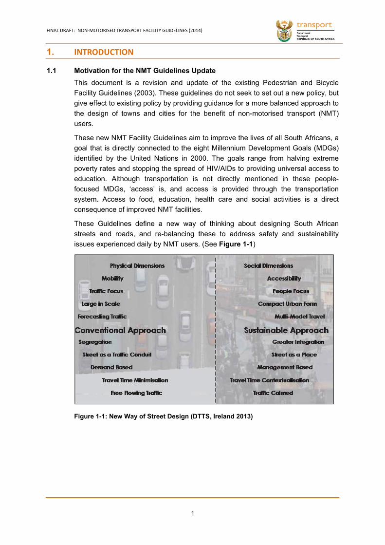
These Guidelines define a new way of thinking about designing South African
streets and roads, and re-balancing these to address safety and sustainability
issues experienced daily by NMT users. (See Figure 1-1)
Figure 1-1: New Way of Street Design (DTTS, Ireland 2013)
FINAL DRAFT: NON‐MOTORISED TRANSPORT FACILITY GUIDELINES (2014)
2
South Africa’s Mobility Status-Quo 1.1.1
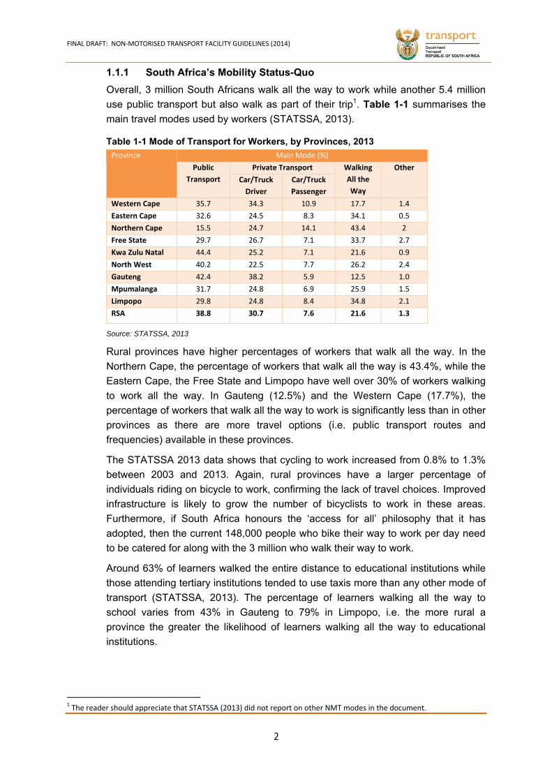
Overall, 3 million South Africans walk all the way to work while another 5.4 million
use public transport but also walk as part of their trip1. Table 1-1 summarises the
main travel modes used by workers (STATSSA, 2013).
Province Main Mode (%)
Public
Transport
Private Transport Walking
All the
Way
Other
Car/Truck
Driver
Car/Truck
Passenger
Western Cape 35.7 34.3 10.9 17.7 1.4
Eastern Cape 32.6 24.5 8.3 34.1 0.5
Northern Cape 15.5 24.7 14.1 43.4 2
Free State 29.7 26.7 7.1 33.7 2.7
Kwa Zulu Natal 44.4 25.2 7.1 21.6 0.9
North West 40.2 22.5 7.7 26.2 2.4
Gauteng 42.4 38.2 5.9 12.5 1.0
Mpumalanga 31.7 24.8 6.9 25.9 1.5
Limpopo 29.8 24.8 8.4 34.8 2.1
RSA 38.8 30.7 7.6 21.6 1.3
Source: STATSSA, 2013
Rural provinces have higher percentages of workers that walk all the way. In the
Northern Cape, the percentage of workers that walk all the way is 43.4%, while the
Eastern Cape, the Free State and Limpopo have well over 30% of workers walking
to work all the way. In Gauteng (12.5%) and the Western Cape (17.7%), the
percentage of workers that walk all the way to work is significantly less than in other
provinces as there are more travel options (i.e. public transport routes and
frequencies) available in these provinces.
The STATSSA 2013 data shows that cycling to work increased from 0.8% to 1.3%
between 2003 and 2013. Again, rural provinces have a larger percentage of
individuals riding on bicycle to work, confirming the lack of travel choices. Improved
infrastructure is likely to grow the number of bicyclists to work in these areas.
Furthermore, if South Africa honours the ‘access for all’ philosophy that it has
adopted, then the current 148,000 people who bike their way to work per day need
to be catered for along with the 3 million who walk their way to work.
Around 63% of learners walked the entire distance to educational institutions while
those attending tertiary institutions tended to use taxis more than any other mode of
transport (STATSSA, 2013). The percentage of learners walking all the way to
school varies from 43% in Gauteng to 79% in Limpopo, i.e. the more rural a
province the greater the likelihood of learners walking all the way to educational
institutions.
1 The reader should appreciate that STATSSA (2013) did not report on other NMT modes in the document.
Table 1-1 Mode of Transport for Workers, by Provinces, 2013
FINAL DRAFT: NON‐MOTORISED TRANSPORT FACILITY GUIDELINES (2014)
3
South Africa’s Road Safety Challenge 1.1.2
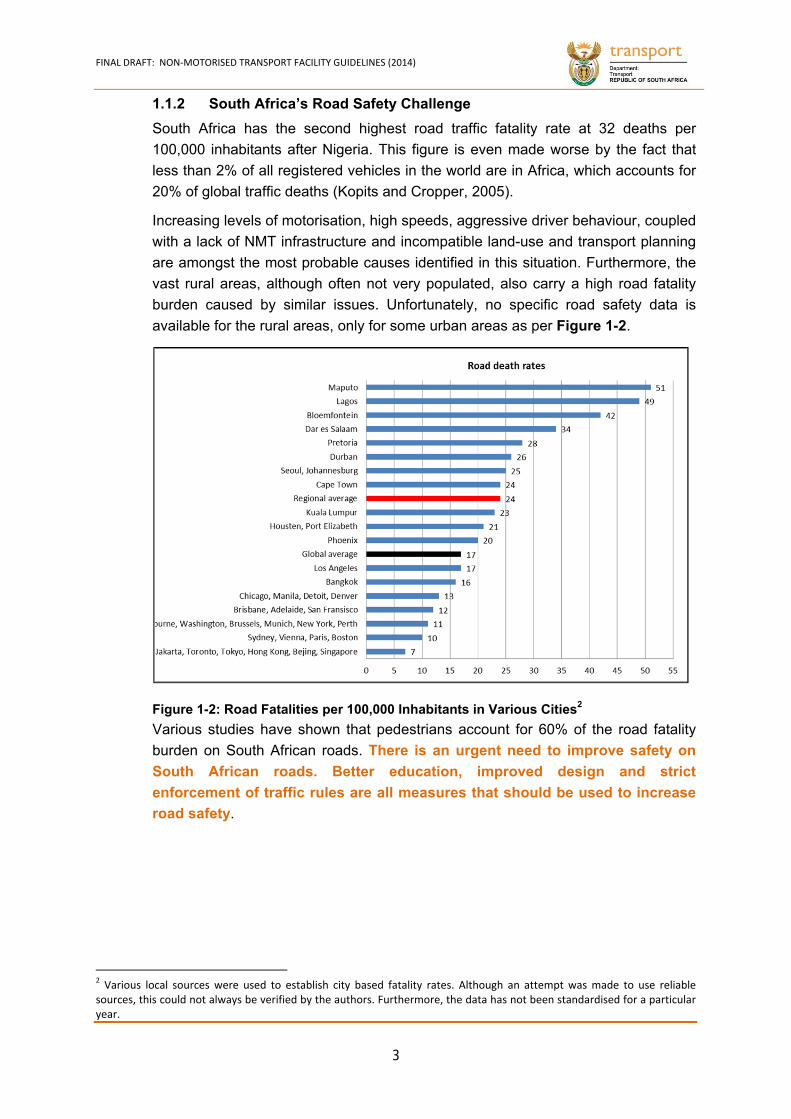
South Africa has the second highest road traffic fatality rate at 32 deaths per
100,000 inhabitants after Nigeria. This figure is even made worse by the fact that
less than 2% of all registered vehicles in the world are in Africa, which accounts for
20% of global traffic deaths (Kopits and Cropper, 2005).
Increasing levels of motorisation, high speeds, aggressive driver behaviour, coupled
with a lack of NMT infrastructure and incompatible land-use and transport planning
are amongst the most probable causes identified in this situation. Furthermore, the
vast rural areas, although often not very populated, also carry a high road fatality
burden caused by similar issues. Unfortunately, no specific road safety data is
available for the rural areas, only for some urban areas as per Figure 1-2.
Various studies have shown that pedestrians account for 60% of the road fatality
burden on South African roads. There is an urgent need to improve safety on
South African roads. Better education, improved design and strict
enforcement of traffic rules are all measures that should be used to increase
road safety.
2 Various local sources were used to establish city based fatality rates. Although an attempt was made to use reliable sources, this could not always be verified by the authors. Furthermore, the data has not been standardised for a particular year.
Figure 1-2: Road Fatalities per 100,000 Inhabitants in Various Cities2
FINAL DRAFT: NON‐MOTORISED TRANSPORT FACILITY GUIDELINES (2014)
4
Effects of Speed on Pedestrian Facilities 1.1.3
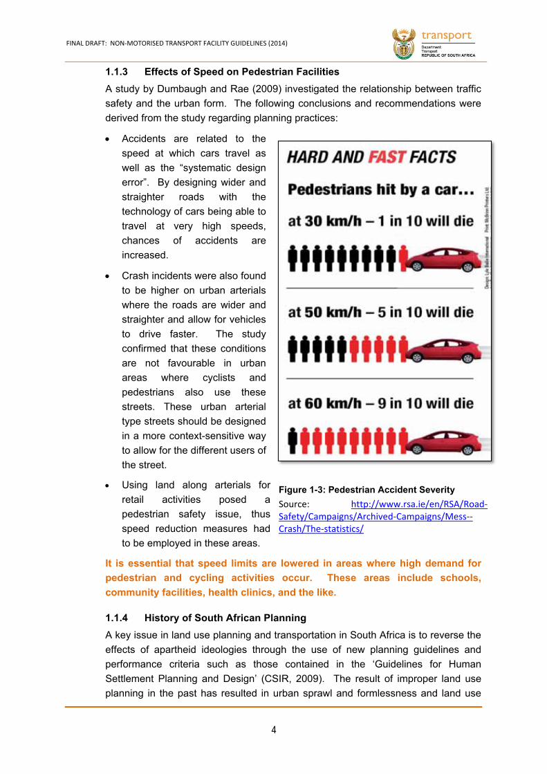
A study by Dumbaugh and Rae (2009) investigated the relationship between traffic
safety and the urban form. The following conclusions and recommendations were
derived from the study regarding planning practices:
Accidents are related to the
speed at which cars travel as
well as the “systematic design
error”. By designing wider and
straighter roads with the
technology of cars being able to
travel at very high speeds,
chances of accidents are
increased.
Crash incidents were also found
to be higher on urban arterials
where the roads are wider and
straighter and allow for vehicles
to drive faster. The study
confirmed that these conditions
are not favourable in urban
areas where cyclists and
pedestrians also use these
streets. These urban arterial
type streets should be designed
in a more context-sensitive way
to allow for the different users of
the street.
Using land along arterials for
retail activities posed a
pedestrian safety issue, thus
speed reduction measures had
to be employed in these areas.
It is essential that speed limits are lowered in areas where high demand for
pedestrian and cycling activities occur. These areas include schools,
community facilities, health clinics, and the like.
History of South African Planning 1.1.4
A key issue in land use planning and transportation in South Africa is to reverse the
effects of apartheid ideologies through the use of new planning guidelines and
performance criteria such as those contained in the ‘Guidelines for Human
Settlement Planning and Design’ (CSIR, 2009). The result of improper land use
planning in the past has resulted in urban sprawl and formlessness and land use
Figure 1-3: Pedestrian Accident Severity
Source: http://www.rsa.ie/en/RSA/Road‐Safety/Campaigns/Archived‐Campaigns/Mess‐‐Crash/The‐statistics/
FINAL DRAFT: NON‐MOTORISED TRANSPORT FACILITY GUIDELINES (2014)
5
development, which contradicts some key principles of urban design and transport
planning.
This document supports the application of the transport user hierarchy when
planning and designing settlements should be applied – i.e. consider the needs of
the most vulnerable users first: pedestrians, then cyclists, then public transport
users, specialist vehicles like ambulances and finally other motor vehicles. This can
only occur by creating a more ‘people focused’ environment through careful NMT
network planning and detailed design.
As South Africa is striving to become a more equitable nation, and with the general
realisation that alternatives to car-orientated lifestyle need to be found to ensure
sustainability, road planning practice in South Africa has to gradually change
towards a people focused approach, concentrated on the implementation of NMT
and PT facilities.
In addition, universal design/access (UD or UA), which involves the provision of
infrastructure and services that cater for the widest range of people possible, is also
gaining focus and momentum. This philosophy has been included in these revised
NMT Facility Guidelines.
Therefore, the NMT Facility Guidelines aim to enhance integrated transport to
ensure that the proper movement (or mobility) of people will be able to
increase safety, reduce fatalities, produce a universally designed
infrastructure and improve equity for all road users.
1.2 Methodology Undertaken
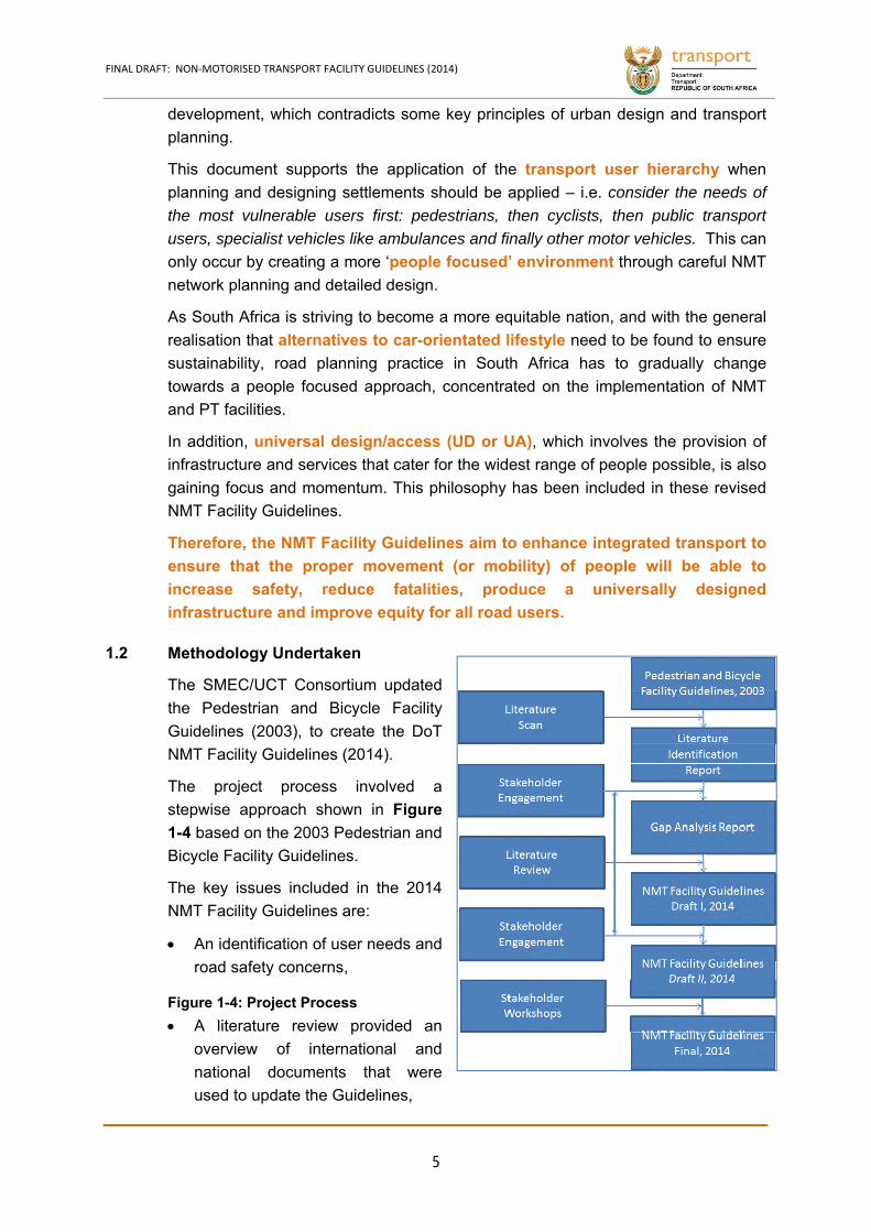
The SMEC/UCT Consortium updated
the Pedestrian and Bicycle Facility
Guidelines (2003), to create the DoT
NMT Facility Guidelines (2014).
The project process involved a
stepwise approach shown in Figure
1-4 based on the 2003 Pedestrian and
Bicycle Facility Guidelines.
The key issues included in the 2014
NMT Facility Guidelines are:
An identification of user needs and
road safety concerns,
A literature review provided an
overview of international and
national documents that were
used to update the Guidelines,
Figure 1-4: Project Process
FINAL DRAFT: NON‐MOTORISED TRANSPORT FACILITY GUIDELINES (2014)
6
An overview of legislation informing NMT planning and design,
Various national and international universal access design standards,
An overview of intersection (crossing) designs,
The integration of NMT into specific facilities, such as residential areas, office
areas, public transport facilities, bicycle rental and parking facilities,
The role that road classification plays in planning for and designing for NMT,
Enforcement as well as appraisal techniques and maintenance of NMT
infrastructure, and
Surfaces and pavement types.
Stakeholder engagement contributed to the development of the NMT Facility
Guidelines (2014), first in draft and then in its final draft format. The final draft was
verified through nine stakeholder workshops in each of the South African provinces.
1.3 How to Use the NMT Facility Guidelines
The NMT Facility Guidelines aim to provide an easy-to-use guide for practitioners
interested in cycling, walking and other NMT uses in urban and rural areas. These
guidelines should assist to carry out the planning, design and implementation of
facilities as well as maintenance programmes for NMT infrastructure, while
encouraging a consist provision of facilities, to the best possible standards.
The guidelines summarise the legal, policy and strategy context of NMT planning
and implementation. For users of these Guidelines that are not familiar with this, it is
of utmost importance to read Chapter 2.
At the core of all-spatial planning is zoning, land-use planning and actual land uses.
Bad land-use planning, as well as the development of informal settlements without
proper planning, leads to many road safety challenges, such as the need to cross
freeways. Land-use planning, however, falls outside the scope of these NMT
Facility Guidelines.
The NMT Facility Guidelines reiterate the importance of connecting national policy
goals to a local network and facility level through proper network planning. This is
described in Chapter 3. Furthermore, a simple network development tool is
included.
Once the network and demand is established, the design of facilities needs to
follow. Chapters 4 and 5 provide guidance, designs, descriptions, pictures of
various best and worst NMT practices, while Chapter 6 details NMT facilities at
places such as public transport hubs, schools, etc. Chapter 7 and 8 deal with
capacity analysis and the pavement design aspects, Chapter 9 tackles
maintenance, and lastly, Chapter 10 details the operational aspects of NMT
facilities.
FINAL DRAFT: NON‐MOTORISED TRANSPORT FACILITY GUIDELINES (2014)
7
The NMT Facility Guidelines are not meant to replace the experience of an
engineer during local designs, or a transport planner detailing the network. Every
situation has specific contextual requirements. The aim of this document is not to
provide detailed designs for all possible situations but indicative designs with
possible minimum dimensions where applicable. While this guide is
comprehensive, it is impossible to predict all challenges encountered in practice
when planning and designing NMT facilities.
Lastly, these guidelines should be used in conjunction with other guidelines and
standards for road design, such as:
UTG 7 – Committee of Urban Transport Authorities (Geometric Design of Urban
Local Residential Streets),
Highway Capacity Manual (HCM, 2000 and HCM2010),
Red Book, Volume 1 and Volume 2,
South African Road Traffic Signs Manual (SARTSM, Manual),
South African Pavement Engineering Manual (SAPEM),
COLTO Standard Specification for Roads and Bridge Works,
SANRAL Routine Road Maintenance Manual (SARRMM), and
SANS 10400 Part S and SANS784 – Universal Design Minimum Standards.
CHAPTER 2
FINAL DRAFT: NON‐MOTORISED TRANSPORT FACILITY GUIDELINES (2014)
8
2. POLICY AND LEGISLATION
“NMT: The Universal Mode of Transport.”
2.1 Policy Framework
South Africa has made significant strides in improving the status and attention given
to NMT. A summary of the policies guiding NMT are set out below.
White Paper on National Transport Policy, 1996 2.1.1
One of the policy principles of the White Paper is “to encourage, promote and
etc.plan for the use of non-motorised transport where appropriate” (Land Passenger
Transport Chapter, Strategic Objectives). The White Paper also states that “the
use of more energy-efficient and less pollutant modes of transport will be
promoted. Greater energy awareness will be fostered in both planners and users of
land passenger transport through public awareness programmes, differential fuel
prices, etc.”
National Land Transport Strategic Framework, 2006 (NLTSF) 2.1.2
The framework provides a sound basis for the promotion of NMT, and strategies
and actions are provided in order to achieve this.
The NLTSF suggests that planning authorities need to build, expand and
maintain continuous networks of formal walkways (sidewalks, off-road paths,
safe crossings, and the like.) and dedicated bicycle lanes along lines of high
demand.
To achieve this, transport plans should assess the status quo and the needs for
NMT infrastructure and plan for its design, implementation and maintenance.
Planning for NMT needs will consider NMT both as a main mode and as a
feeder mode linking communities to public transport facilities.
In rural areas, off-road footpaths, trails and tracks need to be included in the
scope of planned rural transport infrastructure.
In rural areas, animal-drawn carts and other intermediate means of transport will
also be supported in transport plans where appropriate.
The NLTSF also indicates that walking and cycling should be promoted as the
preferred modes in South Africa for appropriate distances and this can be realised
through the following:
Government actively promotes walking and cycling with the expanded provision
of NMT infrastructure as the preferred modes of transport over the appropriate
distance ranges for these modes.
Where people are walking excessively long distances on their routine journeys,
transport plans should assess the scope for measures to support cycling,
FINAL DRAFT: NON‐MOTORISED TRANSPORT FACILITY GUIDELINES (2014)
9
particularly for scholars. Both infrastructural measures and supporting services
such as bicycle repair services should be considered.
Successful demonstration projects promoting NMT are initiated and rolled out to
other areas.
Public Transport Strategy and Action Plan, 2007 2.1.3
This is a central policy document on public transport, highlighting the creation of
integrated rapid public transport networks (IRPTNs), wherein NMT is the key
aspect of the ‘first mile’ and ‘last mile’ of a trip. The intention is to introduce
public transport that would reduce unacceptable walking distances and improve
NMT links to public transport.
The Public Transport Strategy discusses “high quality non-motorised transport
networks”. It provides that NMT, particularly walking and cycling, will serve as an
important mode of transport in the proposed IRPTNs. It provides that actions to
improve NMT linkages fall into typical infrastructure development categories of
planning, design, implementation and maintenance.
Rural Transport Strategy for South Africa, 2007 2.1.4
This strategy document shows that it is important to focus on transport in rural as
well as urban areas. One of the goals of this strategy is “the promotion of non-
motorised transport”. The provision of rural transport infrastructure and services
is a way of creating sustainable economic development, empowering people
socially and addressing the issue of poverty. Strategic thrusts include:
The promotion of coordinated rural modal linkage development
The development of demand-responsive, balanced and sustainable rural
transport systems
Department of Transport Draft Policy Document on NMT 2.1.5
This policy states that the DoT will cooperate with relevant government
departments and stakeholders in developing an institutional and legal
framework that responds positively to the needs and implementation of the
NMT system.
This policy states that the primary objectives are, amongst others, to:
Increase the role of NMT as one of the key transport modes,
Integrate NMT as an essential element of public transport and provide a safe
NMT infrastructure, and
Allocate adequate and sustainable funding for the development and promotion
of NMT.
The document also states that non-motorised transport will be provided on the basis
of a number of principles including the need to improve the quality of life, energy
FINAL DRAFT: NON‐MOTORISED TRANSPORT FACILITY GUIDELINES (2014)
10
conservation and safety. The policy also recognises the main components of non-
motorised transport as animal-drawn transport, cycling and walking.
2.2 Legislative Framework
The following sections provide an overview
of the main provisions in South African
legislation that influence the design and
safety of NMT facilities and activities.
Areas of focus are pedestrians (including
people with prams, pregnant women,
children, people accompanying children
and walking in groups, elderly people,
people with disabilities and people carrying
or moving loads), cyclists and Animal-
Drawn Vehicles (ADVs).
Legislation in all three spheres of government is considered.
The Constitution of the Republic of South Africa, 1996, provides that the National
Parliament may make and administer laws within the functional areas of public
transport, environment and road traffic regulation. Provinces may make laws on
matters such as provincial planning, provincial roads, traffic and public transport.
The Constitution also provides that a municipality may make and administer by-laws
for the effective administration of matters related to municipal public transport,
municipal roads, municipal planning and traffic and parking.
In the Bill of Rights, state organisations are mandated to promote a safe and
healthy environment for all persons.
Chapter 3 of the Constitution provides for a cooperative government where state
organisations collaborate with one another in mutual trust and good faith by
coordinating their actions and legislation.
The rights of people with disabilities are also protected by the country’s
Constitution, which stipulates that governmental departments and state bodies have
a responsibility to ensure that concrete steps are taken so that people with
disabilities are able to access the same fundamental rights and responsibilities as
persons without disabilities.
National Land Transport Act 5 of 2009 (NLTA) 2.2.1
The NLTA provides that the Minister of Transport must facilitate the increased use
of public transport and, in taking measures relating to public transport, must
promote the safety of passengers, promote a strategic and integrated approach to
FINAL DRAFT: NON‐MOTORISED TRANSPORT FACILITY GUIDELINES (2014)
11
the provision of public transport and promote the efficient use of energy resources
and limit adverse environmental impacts in relation to land transport3.
Section 36 provides that every municipality must produce an Integrated Transport
Plan (ITP). In doing so they must comply with the Minimum Requirements for
Integrated Transport Plans4 which require the larger municipalities to produce a
Comprehensive Integrated Transport Plan (CITP) including a Transport Needs
Assessment that must give due attention to NMT. CITPs must also include an NMT
strategy. Municipal ITPs are binding on everyone, including organs of state5, and
can be used as a tool to enforce the provision and maintenance of NMT
infrastructure. They must be updated annually and “overhauled” every five years.
The guidelines provide that like the infrastructure required for vehicles, the
infrastructure required for NMT consists of a network of routes, or “ways”, safe
crossings and amenities for the applicable mode. Guidelines are available providing
the details for the design and planning of the infrastructure6.
Section 35 of the NLTA provides that each province must produce a Provincial Land
Transport Framework (PLTF). This must be done according to the terms of the
Regulations Relating to Minimum Requirements for the Preparation of Provincial
Land Transport Frameworks, 20117. These Regulations provide that in preparing
the PLTFs, non-motorised forms of transport must be taken into account8. The
Regulations also provide that the PLTFs must contain a chapter on “non-motorised
and environmentally sustainable transport”9 including, amongst others:
An indication of how NMT is provided for in the general road plan of the
province.
The integration of NMT planning with land transport and land use planning.
The improvement and expansion of pedestrian sidewalks and dedicated public
space to interlink public transport stations, ranks and other facilities in city areas
along provincial roads.
The provision of dedicated NMT facilities and infrastructure along provincial
roads (e.g. infrastructure for wheelchairs, pedestrian walkways, foot bridges,
overhead bridges and interchanges).
A detailed strategy to promote and encourage NMT in rural or urban areas if so
requested by the relevant planning authority (municipality) which must include
an NMT policy, a cycling master plan, a walking master plan and an animal-
drawn transportation plan if ADT is significant in the province.
3 Section 5 4 Government Notice R.1119 of 30 November 2007 5 Section 38 6See the DoT Pedestrian and Bicycle Facility Guidelines dated August 2003 which contain detailed guidelines and recommended
specifications for pedestrian and bicycle facilities 7Published under Notice R.825 in Government Gazette 34657 of 3 October 2011 8Regulation 3(2)(c)
9 Regulation 6(2)
FINAL DRAFT: NON‐MOTORISED TRANSPORT FACILITY GUIDELINES (2014)
12
The PLTF must also include a transport infrastructure strategy.
A section of the PLTFs has been examined, some of which deal quite extensively
with NMT issues. Section 11(1) (c) (xvii) of the NLTA provides that all municipalities
have the duty of “undertaking functions relating to municipal roads, as well as
measures to limit damage to the road system”.
The National Road Traffic Act 93 of 1996 (NRTA) 2.2.2
The NRTA deals with issues such as vehicle and
driver fitness, rules of the road, traffic signs and
signals and related matters.
For example, the NRTA makes it an offence to
drive a vehicle recklessly or negligently or in an
inconsiderate manner, i.e. without reasonable
consideration for any other person using the
road10. It is also an offence to fail to obey a road
traffic sign, unless directed to do so by a traffic
officer11. Road traffic signs, signals and markings
are described in Chapter IX and shown in
Schedule 2 of the NRT Regulations (See below).
National Road Traffic Regulations, 2000 (NRT Regulations) 2.2.3
The NRT Regulations have been published by the Minister of Transport in terms of
the NRTA and contain various provisions that impact on NMT and its associated
facilities, such as public roads used by bicycles, pedestrians and animal-drawn
carts, amongst other issues.
They provide that no one may drive a vehicle on a sidewalk12. The definition of
“vehicle” includes bicycles. This could be a limiting factor in promoting NMT. A
sidewalk is defined as that portion of a verge intended for the exclusive use of
pedestrians. “Verge” is defined as that portion of a road, street or thoroughfare,
including the sidewalk, which is not the roadway or the shoulder13.
Chapter X of the NRT Regulations deals with rules of the road and related matters.
Where a portion of a public road has been set aside for pedal bicycles (bicycles and
tricycles propelled by human power – i.e. a bicycle lane), no one may ride a pedal
cycle on any other portion of the road14. This could be a limiting factor in the design
of bicycle paths or lanes on roads.
Animal-drawn vehicles (ADVs) are allowed on public roads15. Regulation 314 deals
with ADVs, and contains various requirements such as that the name and address
10 Sections 63(1) and 64
11Section 58(1)
12 Regulation 308(5)
13 Section 1 of the NRTA
14 Regulation 311(7)
15 Regulation 313(2)(a)
FINAL DRAFT: NON‐MOTORISED TRANSPORT FACILITY GUIDELINES (2014)
13
of the owner must be displayed on the vehicle. Regulation 315 contains provisions
protecting pedestrians at road crossings. Where a pedestrian crossing is situated in
an intersection with a traffic signal, pedestrians may not enter the crossing unless
the signal allows it. Drivers of vehicles must yield right of way to pedestrians
crossing at pedestrian crossings. Pedestrians may not enter a pedestrian
crossing suddenly so that vehicles are unable to yield to them. When a vehicle is
stopped at a pedestrian crossing, other drivers may not pass the vehicle from
the rear. Pedestrian crossings should be designed so as to facilitate these
requirements.
Other duties of pedestrians are set out in Regulation 316. Where a sidewalk or
footpath is provided, a pedestrian may not walk on the roadway except to cross the
road. Where there is no sidewalk or footpath, pedestrians must walk as near as
practicable to the right hand side of the road to face oncoming traffic, unless the
presence of pedestrians is prohibited by a road traffic sign. Pedestrians crossing
roads must exercise due care for their safety and must not linger on the roadway.
Pedestrians may cross roads only at pedestrian crossings or intersections or at a
distance further than 50 m from such a crossing or intersection.
Duties of cyclists are set out in Regulation 311. A cyclist must sit astride the saddle
of the bicycle. Cyclists must ride in a single file except when overtaking another
cyclist, and two or more cyclists may not overtake another vehicle at the same time.
A cyclist may not grab hold of another bicycle while in motion. A cyclist may not
swerve from side to side. A cyclist may not carry a person, animal or object that
obstructs his/her view or interferes with the control of the bicycle. He/she must
keep at least one hand on the handle-bar. Both wheels of the bicycle must be in
contact with the road/cycle path surface at all times.
Cyclists and passengers on bicycles on a public road must wear a protective helmet
which fits them properly and with the chin straps properly fastened16. Cyclists have
a duty to ensure that passengers on the bicycle who are younger than 14 years old
comply with these requirements17.
Animal-drawn vehicles and pedal cycles may not be operated on a freeway18. The
same applies to vehicles “specially designed, constructed or adapted for the use of
a person suffering from a physical defect or disability” and having a mass less than
250 kg. No one may be on foot on a freeway, with certain limited exceptions19. A
pedal cycle may not tow another vehicle, such as a trailer, on a public road20. This
could be a serious limitation where persons riding pedal cycles used as “tuk-tuks”
(rickshaws), for example, wish to tow a trailer with luggage or goods for sale.
16Regulation 207(2)
17Regulation 207(3)
18 Regulation 323(1)(a) and (b)
19 Regulation 323(2)
20 Regulation 330(g)
FINAL DRAFT: NON‐MOTORISED TRANSPORT FACILITY GUIDELINES (2014)
14
Appropriate road traffic signs, signals and markings must be used to demarcate
bicycle and pedestrian lanes and related infrastructure according to the Road Traffic
Signs Manual attached to the NRT Regulations. These include, for example, signs
reserving bicycle lanes for the exclusive use of bicycles, signs prohibiting vehicles
in pedestrian walkways, and the like.
The use of electric scooters, such as segways, standing scooters and chariot
scooters has been questioned in relation to NMT facilities. These are included in the
definition of “motor vehicle” and “motorcycle” in the NRTA. They are not permitted
on public roads at present, because there are no approved SABS specifications for
them, which means they cannot be registered and licensed. The NRT Regulations
also prohibit the use of motor vehicles on sidewalks.
The DoT has published draft amendments to the NRTA and NRT Regulations to
deal with these types of scooters, but the amendments have not been promulgated
yet. Based on enquiries, it is unlikely that they will be promulgated this year (2014).
Cycle paths will constitute public roads in terms of the definition in the NRTA if they
are commonly used by the public or if the public habitually has access to them.
Motor scooters and other motor vehicles can be excluded from bicycle or pedestrian
paths by putting up road signs.
Administrative Adjudication of Road Traffic Offences Act 46 of 1998 2.2.4
(AARTO Act)
An important feature of legislation affecting NMT is law enforcement. The AARTO
Act provides for a system of administering road traffic offences through an
administrative process rather than through the courts. It also provides for a points
demerit system for road traffic offenders in terms of which penalties are prescribed,
which can include suspension or loss of a driving licence. Regulations have been
made under the AARTO Act providing for penalties and points for the various traffic
offences.21
At present the AARTO system is in force only as pilot projects in the cities of
Tshwane and Johannesburg (the points demerit system is not in force anywhere
yet). In areas where the AARTO Act is not yet in operation, prosecutions for road
traffic offences must be done in terms of the Criminal Procedure Act 51 of 1977.
Where the AARTO Act is in force, municipalities may no longer prescribe their own
penalties or fines for road traffic offences by means of by-laws, but must use the
AARTO system.
National Building Regulations and Building Standards Act 103 of 1977 2.2.5
This Act deals with the erection of buildings and provides for building plans to be
approved by local authorities. The Minister of Economic Development may make
regulations to be known as the National Building Regulations regarding the
21Notice R.753 in Government Gazette 31242 of 16 July 2008
FINAL DRAFT: NON‐MOTORISED TRANSPORT FACILITY GUIDELINES (2014)
15
preparation, submission and approval of building plans and to regulate all aspects
of buildings22.
South African National Roads Agency Limited and National Roads Act 2.2.6
7 of 1998 (SANRAL Act) and Other Roads Legislation
According to the SANRAL Act, the South African National Roads Agency (SANRAL)
is responsible to plan, construct, maintain and finance national roads. SANRAL is
mandated by the Constitution to protect the safety of road users and other affected
persons23. Under the common law, if SANRAL creates a harmful or potentially
harmful situation, or allows such a situation to develop, e.g. potholes, it can be held
liable for damages if persons are killed or injured, or there is damage to property.
The same applies to provincial roads based on various legislation on provincial
roads such as the Eastern Cape Roads Act 3 of 2003, the Western Cape Transport
Infrastructure Act 1 of 2013 and the Gauteng Transport Infrastructure Act 8 of 2001.
The principles also apply to municipal roads.
Apart from the statutory duties (i.e. duties set out by legislation) of road authorities
to maintain roads and other transport infrastructure, including traffic signals, there is
also a duty under a common law for them to maintain roads and other infrastructure
under their control to prevent death or injury of persons and damage to property.
Road authorities are liable to claims if any person is killed or injured, or if a property
is damaged as a result of their failure to do so, e.g. failing to repair potholes or
faulty traffic signals. A number of judgements have been made by the Supreme
Court of Appeal and the High Court in this regard, and these cases are commonly
referred to as the “municipality cases”. Basically, liability arises in the two cases
that follow:
a) Where the road authority creates a danger which was not there before, e.g.
a hole dug in a public road or sidewalk without barriers or signs to warn the
public about it or
b) Where the authority allows infrastructure under its control to degenerate into
a dangerous condition. For example in Moulang v Port Elizabeth
Municipality24, the Municipality was held liable after a person was injured by
stepping into a hole that had developed on a sidewalk which was built by
and was under the control of the Municipality25.
22 Section 17
23 Section 24(a) – everyone has the right to an environment that is not harmful to their health and well‐being
24 1958 (2) SA 518 (AD) 25See also for example Administrator Cape v Preston 1961 (3) SA 562 (A) relating to provincial roads and Fourie v Munisipaliteit van
Malmesbury 1983 (2) SA (C) which related to the duties of a municipality to maintain an airfield under its control (applying the same principles that apply to roads) and Cape Town Municipality v Butters 1996 (1) SA 473 (C) where the relevant duties of the municipality are explained
FINAL DRAFT: NON‐MOTORISED TRANSPORT FACILITY GUIDELINES (2014)
16
National Environmental Management Act 107 of 1998 (NEMA) 2.2.7
NEMA requires that environmental implications must be investigated and a public
participation process must be carried out whenever certain prescribed projects are
undertaken. For example, the building of public facilities and road schemes will
usually require an Environmental Impact Assessment (EIA). The same will apply to
NMT infrastructure, depending on its nature.
National Heritage Resources Act 25 of 1999 2.2.8
This Act requires certain procedures, including public participation, to be
undertaken where a project affects a location or structure of historical significance.
The Act establishes the South African Heritage Resources Association (SAHRA),
which may identify national and provincial heritage sites and protected areas. This
should be kept in mind when designing and building NMT infrastructure which may
affect locations or structures of historical significance.
Promotion of Administrative Justice Act 3 of 2000 (PAJA) 2.2.9
PAJA and its regulations provide that where a state organisation undertakes any
administrative action as defined in the Act, it must notify affected persons and allow
them the opportunity to comment. This can involve either a “notice and comment”
procedure or one or more public hearings. Authorities must comply with PAJA when
performing administrative actions, e.g. establishing NMT facilities in residential
areas that affect the rights of persons.
Legal Requirements for Animal-Drawn Vehicles 2.2.10
National Road Traffic Regulation 187 stipulates that red retro-reflectors be fitted on
rear of certain vehicles, and specifically provides that:
(1) No person shall operate on a public road:
(a) a motor vehicle, other than a motorcycle without side-car or motor
tricycle with one wheel at the rear
(b) a rickshaw or
(c) an animal-drawn vehicle.
unless these are fitted on the rear of such vehicle at the same height two red retro-
reflectors, one on each side, of the longitudinal centre-line thereof and equidistant
therefrom and otherwise complying with the provisions of these regulations:
Provided that in the case of a combination of motor vehicles, both the drawing
vehicle and the rearmost vehicle shall be fitted with such retro-reflectors.
National Road Traffic Regulation 314, meanwhile, enumerates the following
additional requirements for animal-drawn vehicles:
(1) No person shall operate an animal-drawn vehicle on a public road unless the
name and address of the owner thereof is affixed or painted in a conspicuous
FINAL DRAFT: NON‐MOTORISED TRANSPORT FACILITY GUIDELINES (2014)
17
position on the left side of such vehicle in letters not less than 25 millimetres
high: Provided that nothing herein contained shall apply in respect of a
vehicle used solely for the conveyance of persons otherwise than for hire or
reward.
(2) No person shall operate an animal-drawn vehicle on a public road unless the
vehicle and the harness and other equipment thereof are in an efficient and
safe condition.
(3) The owner of an animal-drawn vehicle shall not cause or permit such vehicle
to be used on a public road by any person who is not competent whether by
reason of his or her age or otherwise to drive and control such vehicle.
(4) The driver of an animal-drawn vehicle on a public road shall at all times give
his or her undivided attention to the driving of the vehicle under his or her
control, and if the vehicle is standing on a public road, the driver shall not
cease to retain control over every animal which is still harnessed to the
vehicle, unless some other person competent to do so takes charge of every
such animal, or every such animal is so fastened that it cannot move from the
place where it has been left.
(5) No person shall operate on a public road a vehicle drawn by a team of
animals not controlled by reins, unless there is a person leading the team and
exercising control over such team.
(6) The driver or other person in charge of a vehicle drawn by any animal shall
not, on a public road outside an urban area, permit such vehicle to follow any
other vehicle similarly drawn at a distance of less than 150 metres calculated
from the foremost animal of such first-mentioned vehicle, except for the
purpose of overtaking a vehicle travelling at a slower speed or when a vehicle
travelling at a greater speed, having overtaken such vehicle, is drawing away
from it.
South Africa’s Universal Access Regulations 2.2.11
These are currently being drafted.
Municipal By-Laws 2.2.12
The Constitution, read with the Systems Act, empowers municipalities to make by-
laws on any issue over which they have responsibility, such as municipal roads,
municipal planning, traffic and parking, among others. Some South African cities
are drafting by-laws impacting on NMT and NMT users. However, the following
issues can still be addressed for inclusion in their by-laws:
(a) Issues for Possible Inclusion in By-Laws
There is a general need for legislation in all three spheres of government to address
NMT and, more specifically, NMT infrastructure. Some legislation, e.g. the National
FINAL DRAFT: NON‐MOTORISED TRANSPORT FACILITY GUIDELINES (2014)
18
Road Traffic Regulations, have provisions that could hamper the introduction or
promotion of NMT. The Minister of Transport should be asked to amend them and
remove the restrictions, and possibly introduce measures to promote NMT.
Municipalities need to include the following relevant issues in their future by-laws:
Modify the institutional structure to accommodate NMT. Policy documents
identify that currently the lack of a single point of responsibility within local
government for NMT planning, implementation and maintenance is problematic.
As part of this package of catalytic interventions, it is proposed that the body
accountable for public transport operations and maintenance (i.e. the
municipality as planning authority) should include the operations and
maintenance of NMT priority routes.
Make sure that in the planning and
development of transport infrastructure,
NMT must be considered and promoted,
e.g. by means of dedicated bicycle
lanes, removal or limitation of
obstructions such as road signs in
pedestrian walkways, having secure
lock-up facilities for bicycles, among
others.
Provide standards and minimum
requirements for NMT in public transport
infrastructure.
Make compulsory the provision of shower facilities for workers who use bicycle,
or walk long distances, to work.
Require the municipality to develop vision, mission and objectives for NMT in
the municipal area.
Make rules for the design of local links and roads as well as the provision of
trees, plants, outdoor art, among others, for the beautification of streets.
Identify streets to be closed for the use of pedestrians and cyclists.
Provide for rules for the use of pedicabs, bicycle rental systems.
Make compulsory the inclusion of specified NMT aspects in the municipality’s
integrated transport plan.
Encourage by-laws that promote NMT friendly development.
Figure 2-1: Ad-Hoc Cyclist WarningSigns
FINAL DRAFT: NON‐MOTORISED TRANSPORT FACILITY GUIDELINES (2014)
19
2.3 Connecting Policy and Practice
The above discussion on legislation and regulation provides ample indication of
NMT policy considerations and intent. These policies need to be developed and
turned into practice. The provision of NMT facilities can be reached by achieving
the following broad objectives:
Establishing facilities that will make NMT transport attractive in terms of comfort,
total travel time, cost and safety.
Ensuring that NMT facilities improve the sustainability and affordability of
transport to individuals and society.
Making NMT form an integral part of communities and society to improve
societal interaction and encourage “Ubuntu” (human kindness) values.
Ensuring compliance with legislation which dictates that NMT facilities should
aim to accommodate all potential users including special needs users.
All transport authorities need to consider and set policies and frameworks that will
promote NMT usage. These policies should therefore:
Be appropriate to the purpose of the organisation and its role in the provision of
transport within its jurisdiction.
Set out the specific scope of NMT provision encompassed.
Include a commitment to satisfy quality and universal access requirements.
Be consistent with other relevant organisational policies, budgets and plans.
A commitment to continual improvement of the NMT systems that do not only
meet demand but also aim to increase demand.
Be available as documented information and be carried into municipal by-laws.
Be communicated within the organisation and be available to stakeholders.
2.4 Implementation Processes
Several processes involved in implementing NMT are no different from most
transport system infrastructure development and implementation processes. These
include the distinct development stages of:
Planning,
Concepts, viability and sustainability considerations,
Design,
Construction, and
Operations and maintenance.
Guidelines for each of these processes are provided in the following chapters.

CHAPTER 3
FINAL DRAFT: NON‐MOTORISED TRANSPORT FACILITY GUIDELINES (2014)
20
3. PLANNING
“The NMT Network is only as Good as its Weakest Link.”
3.1 NMT Detail Planning (Project Level Assessments)
The network and route planning approaches discussed in this chapter are meant to
decrease the haphazard provision for walking and cycling by holistically planning
networks and routes for NMT. This is done by translating NMT demand estimates
(actual or predicted) into a complete network, while also looking at constraints such
as existing road classification, user types, among others.
For shorter distances, NMT appears to be the most efficient means of mobility, and
for longer distances, public transport or cars offer greater efficiency. Overall, the
types of facilities that will attract the most users depend on patterns of land use,
land prices, travel needs, topography and the layouts of existing infrastructure and
services.
Planning for NMT is mainly about facilitating movement from origins to their
destinations or to public transport facilities. This is best done through a system of
interconnected routes and networks. This will aid in improvement safety and user
functionality.
With the needs assessment complete and a set of draft project and programmes
identified, the next step in the planning process is to plan the required facilities in
more detail. This includes:
Route planning (layout / separation / NMT facility class)
Intersection planning (finding optimal layouts for different modes)
These are discussed in more detail for various NMT modes below.
Greenfield Planning 3.1.1
While NMT has normally been neglected in the past in planning new urban layouts
and developments, this trend needs to be reversed in future using the following
simple precepts:
NMT should be the first input considered in planning as it requires certain
fundamentals to be adhered to.
NMT will be successful if it is located along contour lines to minimise gradients
while streets and stands can be placed on a rough east-west, north-south grid to
optimise solar conditions in buildings.
NMT can follow watercourses, where appropriate, to provide mobility at right
angles to contours and can be placed within the 1:50 year floodlines in order to
maximise mobility without reducing developable land.
FINAL DRAFT: NON‐MOTORISED TRANSPORT FACILITY GUIDELINES (2014)
21
NMT placement needs to consider safety, user function ability and security to
ensure good and well-lit sightlines and easily controlled access to facilities and
developments.
NMT should be considered as the primary mode of transport for short trips and
scholars.
As long as these precepts are entrenched at the outset, the planning and location of
streets, utilities, stands and facilities can follow. For example, schools should be
located close to the central contour that passes through the development to
minimise the ascending and downhill ride that needs to be overcome by scholars on
bicycles.
Most planning is done with some facilities and infrastructure already in place and
should proceed on the basis of developing facilities that can promote NMT as being
economic, safe and the best form of transport for short (up to 1 km) and medium
distance (up to 5 km) trips. Planning should influence developments which are
normally arranged around car/vehicle access.
NMT Planning within Developed Areas 3.1.2
A few important guidelines need to be recognised while planning within a system of
existing facilities and infrastructure, which includes the following processes:
(i) Status Quo Assessment,
(ii) Situational Analysis,
(iii) Needs Assessment,
(iv) Prioritization Subject to Budget Constraints,
(v) Development of Programmes, and
(vi) Development of Plans.
The above typical planning processes need to be guided by whether the planning
involves:
(vii) Long Term Policies and Programmes,
(viii) Strategic Long Range Planning (10 to 20 years),
(ix) Medium Term Planning (5 to 10 years), and
(x) Short Term Planning and Tactics (1 to 3 years).
FINAL DRAFT: NON‐MOTORISED TRANSPORT FACILITY GUIDELINES (2014)
22
3.2 Pedestrian Route Network Planning
This section will discuss how to go about designing a pedestrian NMT route network
that (1) complies with the network criteria (Section 5.2) and (2) links to form a
complete network while retaining current users of NMT and encouraging more
people to walk safely. The procedure for NMT network planning can be summarised
in six important steps (adapted from LTSA, 2004 and Zuidgeest et al., 2009).
Desire Line Route Assessments 3.2.1
Planning pedestrian routes and networks requires a fair amount of data. Typical
questions that need to be answered upfront and information needed are the
following:
Who are the current users and potential users of NMT facilities? Where the desire lines originating from and what are their destinations i.e. what are the facilities that people need to access within 1km – 5km?
Layout of existing pedestrian desire lines and shortcuts commonly used and where these desire lines intersect or join with public transport routes and major motor vehicle roads.
What role does walking play in the city framework, in terms of the cost, mobility, comfort and accessibility to various modes of transport?
What are currently hazardous road sections on existing roads where it is unsafe for people to walk due to various reasons?
Data that is useful to collect is current and future road traffic volume and speeds; identification of conflict points and crash data; topography as well as the categories of road users.
Base Map to Assess Land Use and Origin and Destinations 3.2.2
Local planning documents map the existing land use, roads and the hierarchy of
roads. They often also contain detailed information about land use zones and
growth areas, major residential subdivisions, commercial or community
developments. They are a most useful source of primary data about likely origins
and destinations of pedestrian trips. Trip desire lines (straight lines connecting the
main origin and destination location) can then be plotted by directly linking the main
origins and destinations using manual or computerised methods (See Figure 3-1).
This allows for making a qualitative assessment of where, on the network,
pedestrian demand is likely to be significant.
A higher concentration of pedestrians can be expected near popular destinations
(trip generators). Hence, an origin-destination survey or a simple mapping of
important future/current NMT origins and destinations is very useful, amongst them
looking at:
Residential areas,
Schools and universities,
Offices and industries,
Shopping areas and markets,
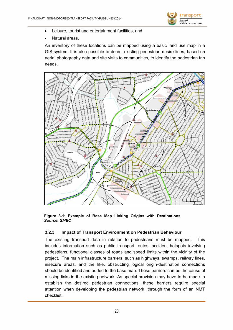
FINAL DRAFT: NON‐MOTORISED TRANSPORT FACILITY GUIDELINES (2014)
23
Leisure, tourist and entertainment facilities, and
Natural areas.
An inventory of these locations can be mapped using a basic land use map in a
GIS-system. It is also possible to detect existing pedestrian desire lines, based on
aerial photography data and site visits to communities, to identify the pedestrian trip
needs.
Impact of Transport Environment on Pedestrian Behaviour 3.2.3
The existing transport data in relation to pedestrians must be mapped. This
includes information such as public transport routes, accident hotspots involving
pedestrians, functional classes of roads and speed limits within the vicinity of the
project. The main infrastructure barriers, such as highways, swamps, railway lines,
insecure areas, and the like, obstructing logical origin-destination connections
should be identified and added to the base map. These barriers can be the cause of
missing links in the existing network. As special provision may have to be made to
establish the desired pedestrian connections, these barriers require special
attention when developing the pedestrian network, through the form of an NMT
checklist.
Figure 3-1: Example of Base Map Linking Origins with Destinations,Source: SMEC
FINAL DRAFT: NON‐MOTORISED TRANSPORT FACILITY GUIDELINES (2014)
24
Tested and Refined Network Based on User Requirements 3.2.4
Field and site surveys of roads/streets would then be conducted on site, to
determine various issues impacting on the walkability of the draft network. This
would determine the value of the draft network, based on the pedestrian user
requirements, as set out in Chapter 4 (Adapted from I-CE, 2000).
(a) Completeness / Coherence
The different route elements should form a coherent unit and link NMT users’ departure and destination points. This includes a consistent and complete network from beginning to end. This requires that:
There must be easy access to main network points of origin and destination.
The NMT network must be integrated with the public transport network.
A hierarchical network approach must be followed (i.e. provision of a city-wide, primary and secondary network).
Routes must not end in the middle of a road corridor i.e. routes must have connectivity. A well-connected network of streets and pedestrian ways means that it is easy for the pedestrian to get around.
(b) Directness
The NMT connections should link NMT users as directly as possible to their destinations. This requires that:
There must be limited detours.
Short-cuts must be used as much as possible over natural or man-made barriers (e.g. railway lines, rivers).
Care must be taken not to plan the NMT route to follow vehicle routes, as NMT users will take the shortest route, where possible.
The network must offer choice between alternative routes for trips with different purposes.
There must be adequate recommendation of crossings (pedestrian crossings; traffic light crossings; underpasses and bridges) to satisfy having the shortest route and the need for a continuous route.
(c) Less Conflict
The NMT network design must ensure that:
Good intersection layouts should be encouraged to avoid conflicts between pedestrians negotiating crossing of roads and streets.
There should be no obstacles within the NMT paths (poles, parked cars, containers, and the like).
(d) Speed Appropriateness
Due to the amount of vulnerable road users on South African streets, it is imperative to introduce speed control measures to improve road safety. This can either take the form of vehicle speed reductions near pedestrian
FINAL DRAFT: NON‐MOTORISED TRANSPORT FACILITY GUIDELINES (2014)
25
precincts and walkways, or completely segregating pedestrians from high volume, high speed vehicles. This requires that the pedestrian network should:
Limit encounters between NMT and high volume, high speed motorised traffic as much as possible through segregation (provision of separate walkways) and traffic calming measures to be employed on collector roads.
Reduce the friction between motor or bicycle traffic and pedestrians wherever possible either by recommending segregated or separated pedestrian routes, or speed reduction.
Be aware of any freight routes that it traverses and the safety needs of pedestrians be taken into consideration at intersections or along route links.
(e) Attractiveness
The NMT facilities should be designed, in such a way as to make them attractive and pleasant for walking and cycling, and safe for use by women and children. This requires that:
Connections should pass through attractive, shaded or green environments that are maintained with gardening services.
Create a pedestrian friendly environment that has a positive relationship to an area’s land use. A mix of complementary land uses and appropriate densities is necessary to make walking a realistic option.
Adequate waste bins and related cleaning and removal services must be provided.
(f) Barrier Free
Movement and information barriers should be kept to a minimum when planning NMT networks. A movement barrier is anything that restricts an individual’s ability to physically move along or within an environment (e.g. travel from one side of a settlement to another). This requires that the planned NMT network should:
Be cognisant of any difficult terrain (e.g. steep slopes, long distances along difficult terrains).
Not have sudden and frequent changes in direction.
Include plans for areas of rest and shelter, especially along long distances.
Be aware of any future conflict or obstacles along the proposed NMT path (e.g. lamp posts, informal activities, benches, property encroachments).
Not expose users to potential hazards (e.g. network which makes pedestrians cross at grade on a multi-lane highway).
Take cognisance of persons who have limited agility, endurance, speed and movement patterns.

FINAL DRAFT: NON‐MOTORISED TRANSPORT FACILITY GUIDELINES (2014)
26
Make appropriate recommendations for information and way-finding systems to prevent barriers caused by lack of information.
(g) Safety
The personal safety of NMT users is of utmost importance in order to maximise usage. The following measures should therefore be adopted:
Personal safety should be taken into account in terms of potential criminal areas of concealment and have clear sight and splayed building and boundary corners wherever possible.
Alternative connections should be available to avoid insecure spots.
Street lights should be provided if not already present.
All vegetation should be controlled and managed to avoid offering shelter to potential criminals, i.e. no vegetation between 0.4 m and 1.5 m above ground unless security is provided.
Parking on walkways should not be allowed.

FINAL DRAFT: NON‐MOTORISED TRANSPORT FACILITY GUIDELINES (2014)
27
3.3 Cycling Route Network Planning
This section provides a ‘systematic’ discussion about how to plan and design for
cycling routes that (1) comply with the objectives of Chapter 4, (2) link to form a
network, and (3) retain current cyclists and encourages more people to bike. In
addition, facilities that complement cycling routes will be discussed. The approach
is derived from LTSA (2004)26.
Inventory 3.3.1
Planning bicycle routes and networks requires a fair amount of data. Typical
questions that need to be answered upfront are:
Who are the current and potential cyclists?
What are the different types of cyclists, their cycling skills and trip motives that the network is designed for?
What is the demand for cycling in an area (frequencies, origins, destinations, purpose/motive, time of the day)?
What are currently hazardous road sections on existing roads that might restrain NMT users from cycling?
Where can cycle routes be developed?
What type of cycling provisions or facilities do cyclists require to bike safely and comfortably?
Determining Needs of Cyclists 3.3.2
The needs of cyclists may differ quite a bit as they may ride their bicycles for
different purposes. In South Africa three types of cyclists are commonly seen: the
recreational cyclist, the commuting (or utilitarian) cyclist and the scholar cyclist. The
scholar cyclists are younger and less adept on their bicycles than adults and
therefore need greater protection and more careful planning to ensure that they are
safe in the transport environment. Their ‘terms of reference’ are different.
Recreational cyclists ride mainly for leisure and place a high value on enjoying the
experience, so they place more value on open spaces, boulevards, parks and
routes separated from traffic. In South Africa, many recreational cyclists race and
bike over long distances at relatively high speeds. They are usually less constrained
by time and vary widely in skill and experience.
In South Africa’s townships and suburban neighbourhoods, a considerable number
of children and adults bike through short distances to schools and/or to the shops.
26http://www.nzta.govt.nz/resources/cycle‐network‐and‐route‐planning/docs/cycle‐network‐and‐route‐planning.pdf
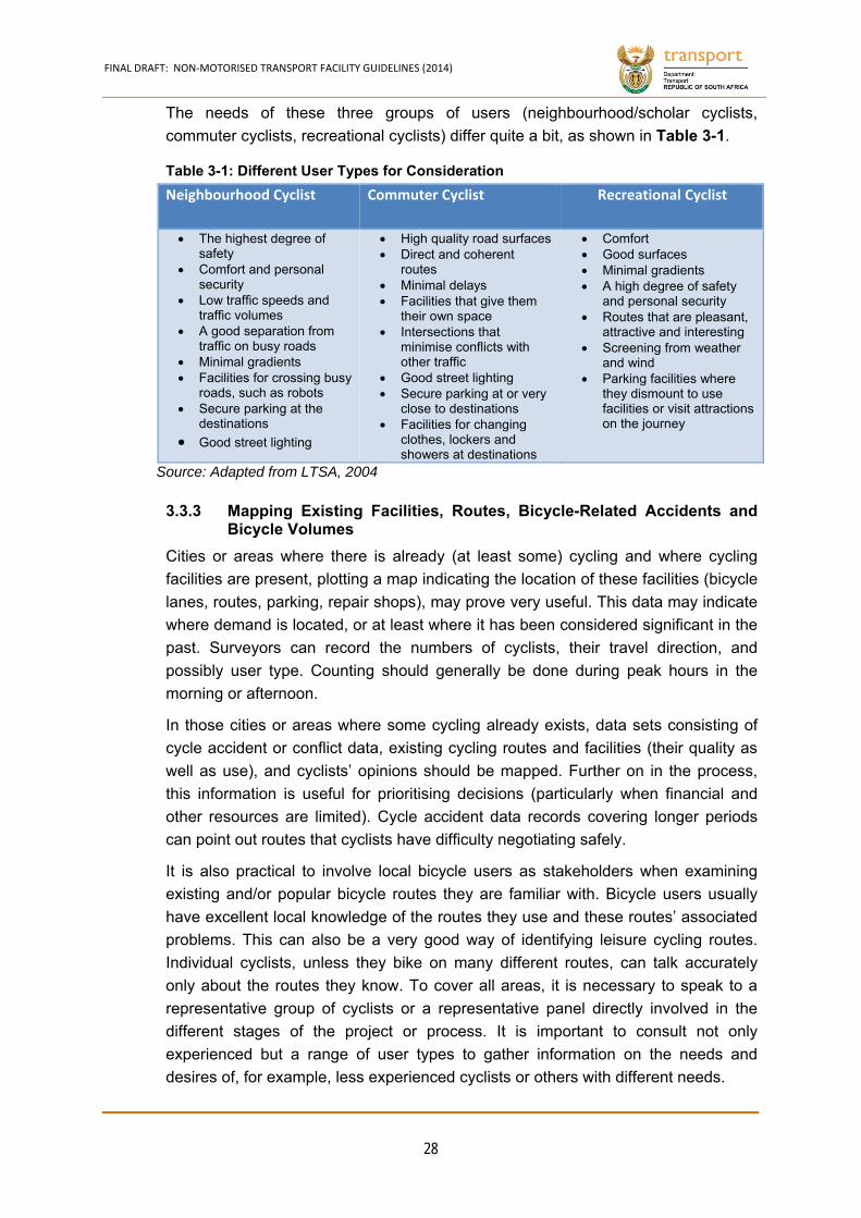
FINAL DRAFT: NON‐MOTORISED TRANSPORT FACILITY GUIDELINES (2014)
28
The needs of these three groups of users (neighbourhood/scholar cyclists,
commuter cyclists, recreational cyclists) differ quite a bit, as shown in Table 3-1.
Neighbourhood Cyclist Commuter Cyclist Recreational Cyclist
The highest degree of safety
Comfort and personal security
Low traffic speeds and traffic volumes
A good separation from traffic on busy roads
Minimal gradients Facilities for crossing busy
roads, such as robots Secure parking at the
destinations
Good street lighting
High quality road surfaces Direct and coherent
routes Minimal delays Facilities that give them
their own space Intersections that
minimise conflicts with other traffic
Good street lighting Secure parking at or very
close to destinations Facilities for changing
clothes, lockers and showers at destinations
Comfort Good surfaces Minimal gradients A high degree of safety
and personal security Routes that are pleasant,
attractive and interesting Screening from weather
and wind Parking facilities where
they dismount to use facilities or visit attractions on the journey
Source: Adapted from LTSA, 2004
Mapping Existing Facilities, Routes, Bicycle-Related Accidents and 3.3.3Bicycle Volumes
Cities or areas where there is already (at least some) cycling and where cycling
facilities are present, plotting a map indicating the location of these facilities (bicycle
lanes, routes, parking, repair shops), may prove very useful. This data may indicate
where demand is located, or at least where it has been considered significant in the
past. Surveyors can record the numbers of cyclists, their travel direction, and
possibly user type. Counting should generally be done during peak hours in the
morning or afternoon.
In those cities or areas where some cycling already exists, data sets consisting of
cycle accident or conflict data, existing cycling routes and facilities (their quality as
well as use), and cyclists’ opinions should be mapped. Further on in the process,
this information is useful for prioritising decisions (particularly when financial and
other resources are limited). Cycle accident data records covering longer periods
can point out routes that cyclists have difficulty negotiating safely.
It is also practical to involve local bicycle users as stakeholders when examining
existing and/or popular bicycle routes they are familiar with. Bicycle users usually
have excellent local knowledge of the routes they use and these routes’ associated
problems. This can also be a very good way of identifying leisure cycling routes.
Individual cyclists, unless they bike on many different routes, can talk accurately
only about the routes they know. To cover all areas, it is necessary to speak to a
representative group of cyclists or a representative panel directly involved in the
different stages of the project or process. It is important to consult not only
experienced but a range of user types to gather information on the needs and
desires of, for example, less experienced cyclists or others with different needs.
Table 3-1: Different User Types for Consideration
FINAL DRAFT: NON‐MOTORISED TRANSPORT FACILITY GUIDELINES (2014)
29
Questionnaires can also be used to administer trip purposes, trip frequency,
average or typical trip lengths, preferences and social-economic background,
amongst others. This information can also be used to ‘identify’ the potential for
cycling, when asking people whether they would cycle if certain facilities are
available.
Special attention should be given to school traffic, as schools may represent points
where bicycle users concentrate, making these trips important, as well as relatively
easy to survey. Questionnaires and counting parked bicycles are commonly used to
assess bicycle demand at schools. By obtaining the number of students attending
school on a survey day, the percentage of students cycling to school can be
calculated. Questionnaire surveys can also provide information on route choice and
(safety) problem areas. The results of the survey can be incorporated into safe
routes to school programs.
Mapping Main Infrastructure Barriers and Identifying Missing 3.3.4Connections
The main infrastructure barriers, such as highways, swamps, railway lines, insecure
areas, amongst others, that obstruct logical origin-destination connections should
be identified and added to the base map. These barriers can be the cause of
missing links in the existing network. As special provisions may have to be made to
establish the desired bicycle connections, these barriers require special attention
when developing the bicycle network.
Assessing and Understanding Potential Demand 3.3.5
Potential demand (also called latent demand) describes potential new bicycle trips,
which are currently suppressed, but could take place if cycling conditions were
improved. Potential demand can be assessed in relation to specific route
improvements or to the whole network. Measuring potential demand requires
understanding factors that influence people’s choice of the bicycle. Surveys of
bicycle users and non-users, which ask about the main constraints (and their order)
when they decide to use or not to use a bicycle, are helpful in this case. Decision-
makers can bring some of these factors under control. For example, in some
situations, potential demand is likely to manifest itself when a sustainable safe
bicycle network is constructed, or when promotional activities have been
undertaken to take away prejudgements on cycling. Putting a number to this
potential is often difficult but a good sense of the potential for cycling can be
obtained this way.
Prioritising Bicycle Network Structure including Route Components 3.3.6
Define and establish the priorities for a bicycle network structure using qualitative or
quantitative methods. Develop individual bicycle route components that together
form routes that are safe, coherent, direct, comfortable and attractive.
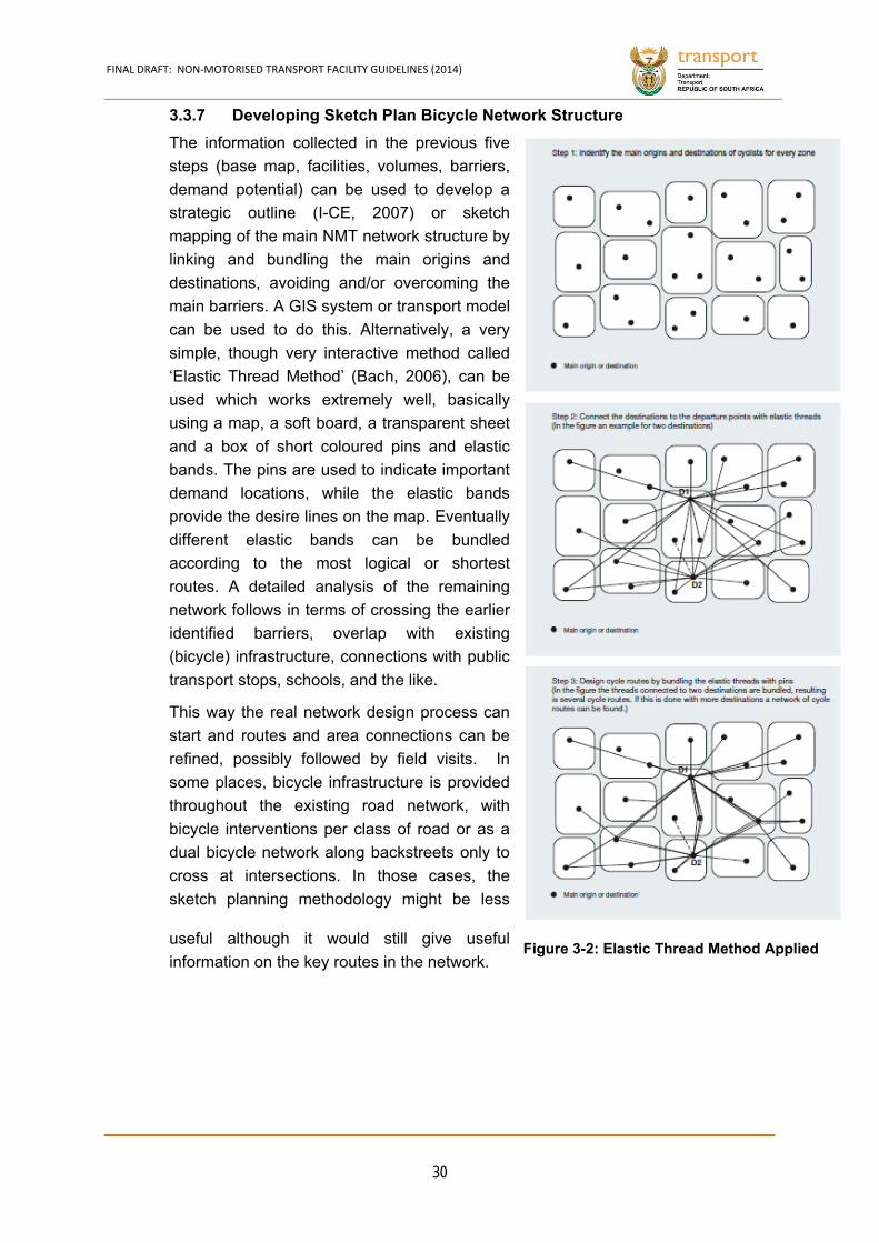
FINAL DRAFT: NON‐MOTORISED TRANSPORT FACILITY GUIDELINES (2014)
30
Developing Sketch Plan Bicycle Network Structure 3.3.7
The information collected in the previous five
steps (base map, facilities, volumes, barriers,
demand potential) can be used to develop a
strategic outline (I-CE, 2007) or sketch
mapping of the main NMT network structure by
linking and bundling the main origins and
destinations, avoiding and/or overcoming the
main barriers. A GIS system or transport model
can be used to do this. Alternatively, a very
simple, though very interactive method called
‘Elastic Thread Method’ (Bach, 2006), can be
used which works extremely well, basically
using a map, a soft board, a transparent sheet
and a box of short coloured pins and elastic
bands. The pins are used to indicate important
demand locations, while the elastic bands
provide the desire lines on the map. Eventually
different elastic bands can be bundled
according to the most logical or shortest
routes. A detailed analysis of the remaining
network follows in terms of crossing the earlier
identified barriers, overlap with existing
(bicycle) infrastructure, connections with public
transport stops, schools, and the like.
This way the real network design process can
start and routes and area connections can be
refined, possibly followed by field visits. In
some places, bicycle infrastructure is provided
throughout the existing road network, with
bicycle interventions per class of road or as a
dual bicycle network along backstreets only to
cross at intersections. In those cases, the
sketch planning methodology might be less
useful although it would still give useful
information on the key routes in the network.
Figure 3-2: Elastic Thread Method Applied
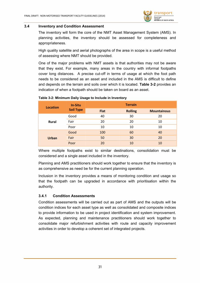
FINAL DRAFT: NON‐MOTORISED TRANSPORT FACILITY GUIDELINES (2014)
31
3.4 Inventory and Condition Assessment
The inventory will form the core of the NMT Asset Management System (AMS). In
planning activities, the inventory should be assessed for completeness and
appropriateness.
High quality satellite and aerial photographs of the area in scope is a useful method
of assessing where NMT should be provided.
One of the major problems with NMT assets is that authorities may not be aware
that they exist. For example, many areas in the country with informal footpaths
cover long distances. A precise cut-off in terms of usage at which the foot path
needs to be considered as an asset and included in the AMS is difficult to define
and depends on the terrain and soils over which it is located. Table 3-2 provides an
indication of when a footpath should be taken on board as an asset.
Location In‐Situ
Soil Type
Terrain
Flat Rolling Mountainous
Rural
Good 40 30 20
Fair 20 20 10
Poor 10 10 10
Urban
Good 100 60 40
Fair 50 30 20
Poor 20 10 10
Where multiple footpaths exist to similar destinations, consolidation must be
considered and a single asset included in the inventory.
Planning and AMS practitioners should work together to ensure that the inventory is
as comprehensive as need be for the current planning operation.
Inclusion in the inventory provides a means of monitoring condition and usage so
that the footpath can be upgraded in accordance with prioritisation within the
authority.
Condition Assessments 3.4.1
Condition assessments will be carried out as part of AMS and the outputs will be
condition indices for each asset type as well as consolidated and composite indices
to provide information to be used in project identification and system improvement.
As expected, planning and maintenance practitioners should work together to
consolidate major refurbishment activities with route and capacity improvement
activities in order to develop a coherent set of integrated projects.
Table 3-2: Minimum Daily Usage to Include in Inventory
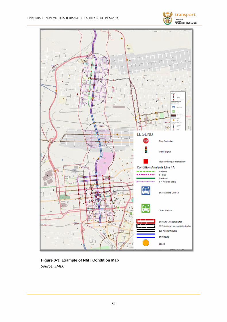
FINAL DRAFT: NON‐MOTORISED TRANSPORT FACILITY GUIDELINES (2014)
32
Source: SMEC
Figure 3-3: Example of NMT Condition Map
FINAL DRAFT: NON‐MOTORISED TRANSPORT FACILITY GUIDELINES (2014)
33
3.5 Determining the Extent of Improvements Required
The situational analysis carried out as part of the AMS can be added to the above
inventory assessment and used as a first input into a needs analysis to determine
the extent and cost of improvements required to achieve desired service levels.
The extent of improvements required to accommodate special needs users can also
be determined and reported.
Overall, the budget levels for NMT facilities should be:
Urban Areas R10 per person per year that lives within the scope of the plan
Rural Areas Depends on public transport interfaces and NMT crossings. An
amount of around R1,000 per km of the paved road network can
be considered as an initial starting point.
The needs assessment should be converted into a set of identified first draft
programmes and projects that will be required to resolve problems.
Prioritisation 3.5.1
Prioritisation should follow the normal project prioritisation processes in use. Two
methods are generally used:
Multi Criteria Analysis, or
Cost-Benefit Analysis.
For NMT a multi-criteria analysis is normally preferred as it is difficult to determine
benefits and costs for NMT in view of the uncertainties associated with quantifying
the benefits. In many cases benefits are of a secondary or tertiary nature such as
increased speed of public transport if all users can use NMT to get to bus stops,
and reduced CO2 emissions due to fewer car trips.
The criteria used in multi-criteria analysis could include:
Number of person-km at a CI below the desired intervention level,
Accident records along the route or at the site,
Potential to improve public transport and reduce subsidies,
Compatibility with strategic plans, and
Degree to which the facility will address stakeholder requirements.
The precise definition of the criteria and analysis will depend on circumstances but
will generally involve weighting the criteria and summing the resulting scores.

FINAL DRAFT: NON‐MOTORISED TRANSPORT FACILITY GUIDELINES (2014)
34
Programmes 3.5.2
The development of NMT programmes provides a method of prioritisation as
dissimilar facilities do not compete for funds individually, but rather as part of a
programme. The programmes then need to compete for funds and the projects
compete within a programme.
Programmes will be developed as an outcome of the situational assessment. Table
3-3 provides some examples.
Situation Problem Programme
Urban - Low CI
Narrow sidewalks Sidewalk widening
Pedestrianisation
One Ways
Unpaved sidewalks Paving sidewalks
Lack of continuity Dedicated walkways and bicycle
lanes
Bicycle lanes
Pedestrianisation
Priority bicycle streets
Gravel walkways within floodlines
Urban - Rural
Pedestrian
Casualties
Dangerous crossings Slow cars down and remove freight
Dangerous crossings Signalised intersection
Poor quality and
dangerous public transport
interfaces
Improve public transport interfaces
Urban Decay Traffic congestion
One Ways with improved sidewalks
and walkways
Continuous bicycle lanes
Low Utilisation
Low take up of bicycle
transport Dedicated bicycle lanes
Low take up of bicycle
transport Bicycle sheds at PT Interfaces
Rural - Low CI
Poor quality footpaths Footpath improvement
Dangerous river and road
crossings Pedestrian/bicycle bridges
Table 3-3: Examples of NMT Programmes
FINAL DRAFT: NON‐MOTORISED TRANSPORT FACILITY GUIDELINES (2014)
35
Viability 3.5.3
Viability concerns the institutional and financial viability of the facilities. This relates
to the cost of sustaining the programme relative to the available budget and the
people available to manage the development, operations and maintenance of the
facilities.
Typically, totally or partially separated paved facilities will cost around R450/m2
while unpaved facilities with gravel wearing courses will cost approximately R50/m2
to develop.
Maintenance costs, around R10/m2 per year, must be added.
Unfortunately, South Africa does not have readily available funds to implement all
NMT infrastructure requirements and improvements. Government will, therefore,
have to prioritise identified projects. Funding should be spent first in areas where
the need is the highest and where the largest number of people will benefit.
Government needs to use national and local policies and legislation, as well as local
conditions (context, attractions and demand) to identify criteria and key
performance indicators that will be used to inform financial decision making. All
planned investments require a calculation of anticipated benefits and costs to
ensure limited funds are allocated to viable projects.
Traditionally, project prioritisation primarily used Cost-Benefit Analysis (CBA). CBA
reduces all the project effects that will occur over time into monetary terms and
compares these with the capital and maintenance costs. CBA uses a discount rate
to take the time value of money into account. While CBA provides a good and
objective numerical indication of the viability of the project, it suffers from the
disadvantage that R1 is deemed to have the same real value to the rich as well as
to the poor. Therefore savings of R1 to many rich people will be deemed to deliver
the same benefit as a R10 saving to 1/10 as many poor people. It therefore
assumes that social equity exists across the spectrum of projects being considered.
An equity analysis or audit is an even more recent approach to prioritisation,
concerned with providing equitable conditions of safety, affordability, comfort,
efficiency, travel time, and a pleasant environment to all.
An equity analysis prioritizes non-drivers over drivers, or people who are transport
disadvantaged over those who own private cars, and ensures that a fair share of
resources are provided to those who do not own their own vehicles.
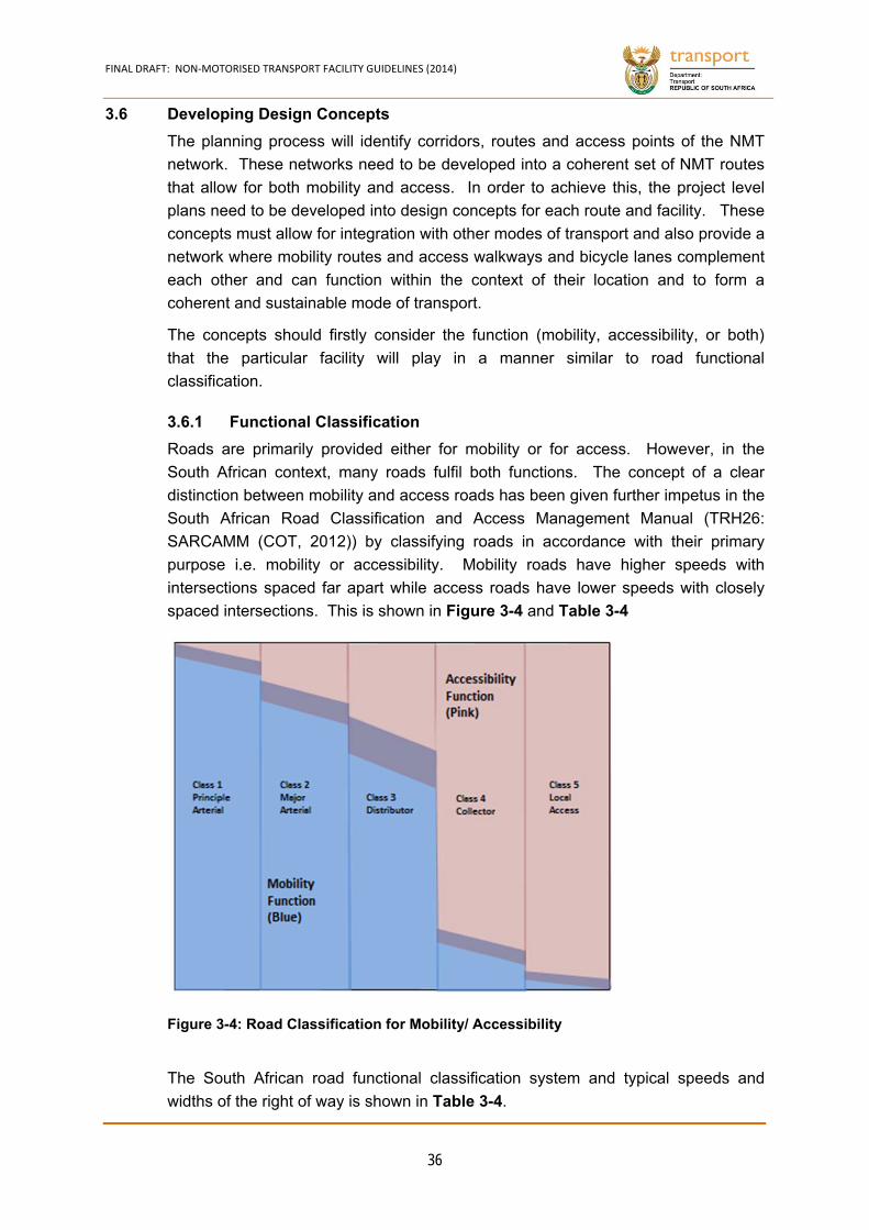
FINAL DRAFT: NON‐MOTORISED TRANSPORT FACILITY GUIDELINES (2014)
36
3.6 Developing Design Concepts
The planning process will identify corridors, routes and access points of the NMT
network. These networks need to be developed into a coherent set of NMT routes
that allow for both mobility and access. In order to achieve this, the project level
plans need to be developed into design concepts for each route and facility. These
concepts must allow for integration with other modes of transport and also provide a
network where mobility routes and access walkways and bicycle lanes complement
each other and can function within the context of their location and to form a
coherent and sustainable mode of transport.
The concepts should firstly consider the function (mobility, accessibility, or both)
that the particular facility will play in a manner similar to road functional
classification.
Functional Classification 3.6.1
Roads are primarily provided either for mobility or for access. However, in the
South African context, many roads fulfil both functions. The concept of a clear
distinction between mobility and access roads has been given further impetus in the
South African Road Classification and Access Management Manual (TRH26:
SARCAMM (COT, 2012)) by classifying roads in accordance with their primary
purpose i.e. mobility or accessibility. Mobility roads have higher speeds with
intersections spaced far apart while access roads have lower speeds with closely
spaced intersections. This is shown in Figure 3-4 and Table 3-4
The South African road functional classification system and typical speeds and
widths of the right of way is shown in Table 3-4.
Figure 3-4: Road Classification for Mobility/ Accessibility
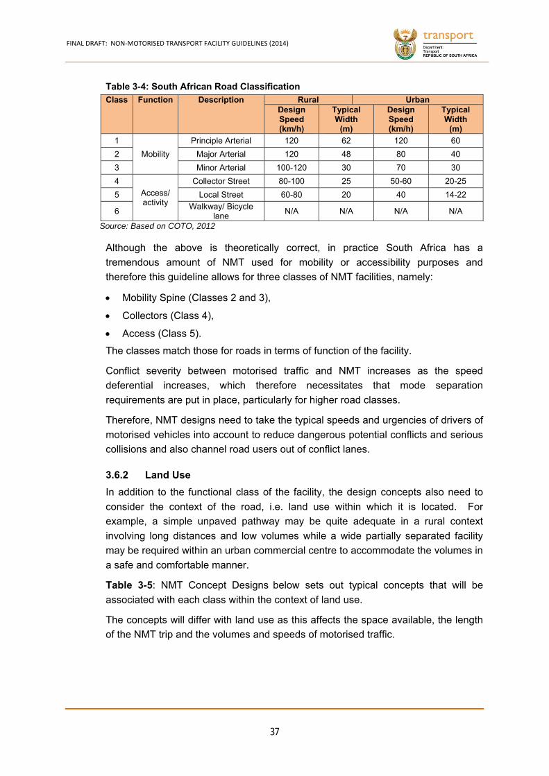
FINAL DRAFT: NON‐MOTORISED TRANSPORT FACILITY GUIDELINES (2014)
37
Class Function Description Rural Urban Design Speed (km/h)
Typical Width
(m)
Design Speed (km/h)
Typical Width
(m)
1
Mobility
Principle Arterial 120 62 120 60
2 Major Arterial 120 48 80 40
3 Minor Arterial 100-120 30 70 30
4
Access/ activity
Collector Street 80-100 25 50-60 20-25
5 Local Street 60-80 20 40 14-22
6 Walkway/ Bicycle
lane N/A N/A N/A N/A
Source: Based on COTO, 2012
Although the above is theoretically correct, in practice South Africa has a
tremendous amount of NMT used for mobility or accessibility purposes and
therefore this guideline allows for three classes of NMT facilities, namely:
Mobility Spine (Classes 2 and 3),
Collectors (Class 4),
Access (Class 5).
The classes match those for roads in terms of function of the facility.
Conflict severity between motorised traffic and NMT increases as the speed
deferential increases, which therefore necessitates that mode separation
requirements are put in place, particularly for higher road classes.
Therefore, NMT designs need to take the typical speeds and urgencies of drivers of
motorised vehicles into account to reduce dangerous potential conflicts and serious
collisions and also channel road users out of conflict lanes.
Land Use 3.6.2
In addition to the functional class of the facility, the design concepts also need to
consider the context of the road, i.e. land use within which it is located. For
example, a simple unpaved pathway may be quite adequate in a rural context
involving long distances and low volumes while a wide partially separated facility
may be required within an urban commercial centre to accommodate the volumes in
a safe and comfortable manner.
Table 3-5: NMT Concept Designs below sets out typical concepts that will be
associated with each class within the context of land use.
The concepts will differ with land use as this affects the space available, the length
of the NMT trip and the volumes and speeds of motorised traffic.
Table 3-4: South African Road Classification
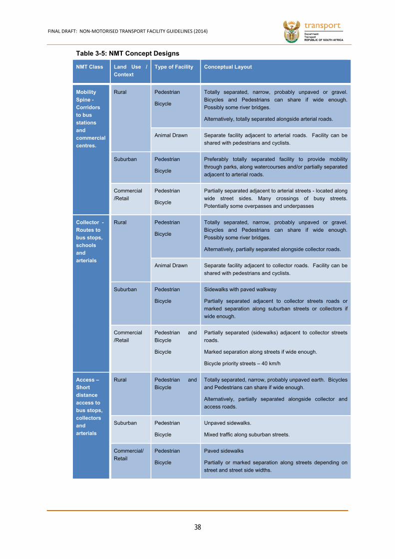
FINAL DRAFT: NON‐MOTORISED TRANSPORT FACILITY GUIDELINES (2014)
38
NMT Class Land Use /
Context
Type of Facility Conceptual Layout
Mobility
Spine -
Corridors
to bus
stations
and
commercial
centres.
Rural Pedestrian
Bicycle
Totally separated, narrow, probably unpaved or gravel.
Bicycles and Pedestrians can share if wide enough.
Possibly some river bridges.
Alternatively, totally separated alongside arterial roads.
Animal Drawn Separate facility adjacent to arterial roads. Facility can be
shared with pedestrians and cyclists.
Suburban Pedestrian
Bicycle
Preferably totally separated facility to provide mobility
through parks, along watercourses and/or partially separated
adjacent to arterial roads.
Commercial
/Retail
Pedestrian
Bicycle
Partially separated adjacent to arterial streets - located along
wide street sides. Many crossings of busy streets.
Potentially some overpasses and underpasses
Collector -
Routes to
bus stops,
schools
and
arterials
Rural Pedestrian
Bicycle
Totally separated, narrow, probably unpaved or gravel.
Bicycles and Pedestrians can share if wide enough.
Possibly some river bridges.
Alternatively, partially separated alongside collector roads.
Animal Drawn Separate facility adjacent to collector roads. Facility can be
shared with pedestrians and cyclists.
Suburban Pedestrian
Bicycle
Sidewalks with paved walkway
Partially separated adjacent to collector streets roads or
marked separation along suburban streets or collectors if
wide enough.
Commercial
/Retail
Pedestrian and
Bicycle
Bicycle
Partially separated (sidewalks) adjacent to collector streets
roads.
Marked separation along streets if wide enough.
Bicycle priority streets – 40 km/h
Access –
Short
distance
access to
bus stops,
collectors
and
arterials
Rural Pedestrian and
Bicycle
Totally separated, narrow, probably unpaved earth. Bicycles
and Pedestrians can share if wide enough.
Alternatively, partially separated alongside collector and
access roads.
Suburban Pedestrian
Bicycle
Unpaved sidewalks.
Mixed traffic along suburban streets.
Commercial/
Retail
Pedestrian
Bicycle
Paved sidewalks
Partially or marked separation along streets depending on
street and street side widths.
Table 3-5: NMT Concept Designs
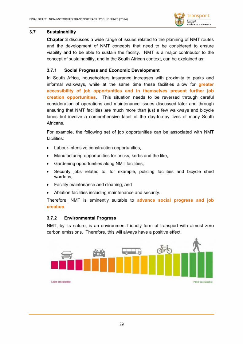
FINAL DRAFT: NON‐MOTORISED TRANSPORT FACILITY GUIDELINES (2014)
39
3.7 Sustainability
Chapter 3 discusses a wide range of issues related to the planning of NMT routes
and the development of NMT concepts that need to be considered to ensure
viability and to be able to sustain the facility. NMT is a major contributor to the
concept of sustainability, and in the South African context, can be explained as:
Social Progress and Economic Development 3.7.1
In South Africa, householders insurance increases with proximity to parks and
informal walkways, while at the same time these facilities allow for greater
accessibility of job opportunities and in themselves present further job
creation opportunities. This situation needs to be reversed through careful
consideration of operations and maintenance issues discussed later and through
ensuring that NMT facilities are much more than just a few walkways and bicycle
lanes but involve a comprehensive facet of the day-to-day lives of many South
Africans.
For example, the following set of job opportunities can be associated with NMT
facilities:
Labour-intensive construction opportunities,
Manufacturing opportunities for bricks, kerbs and the like,
Gardening opportunities along NMT facilities,
Security jobs related to, for example, policing facilities and bicycle shed wardens,
Facility maintenance and cleaning, and
Ablution facilities including maintenance and security.
Therefore, NMT is eminently suitable to advance social progress and job
creation.
Environmental Progress 3.7.2
NMT, by its nature, is an environment-friendly form of transport with almost zero
carbon emissions. Therefore, this will always have a positive effect.

CHAPTER 4
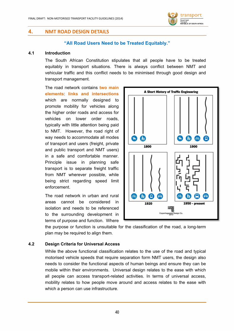
FINAL DRAFT: NON‐MOTORISED TRANSPORT FACILITY GUIDELINES (2014)
40
4. NMT ROAD DESIGN DETAILS
“All Road Users Need to be Treated Equitably.”
4.1 Introduction
The South African Constitution stipulates that all people have to be treated
equitably in transport situations. There is always conflict between NMT and
vehicular traffic and this conflict needs to be minimised through good design and
transport management.
The road network contains two main
elements: links and intersections
which are normally designed to
promote mobility for vehicles along
the higher order roads and access for
vehicles on lower order roads,
typically with little attention being paid
to NMT. However, the road right of
way needs to accommodate all modes
of transport and users (freight, private
and public transport and NMT users)
in a safe and comfortable manner.
Principle issue in planning safe
transport is to separate freight traffic
from NMT wherever possible, while
being strict regarding speed limit
enforcement.
The road network in urban and rural
areas cannot be considered in
isolation and needs to be referenced
to the surrounding development in
terms of purpose and function. Where
the purpose or function is unsuitable for the classification of the road, a long-term
plan may be required to align them.
4.2 Design Criteria for Universal Access
While the above functional classification relates to the use of the road and typical
motorised vehicle speeds that require separation form NMT users, the design also
needs to consider the functional aspects of human beings and ensure they can be
mobile within their environments. Universal design relates to the ease with which
all people can access transport-related activities. In terms of universal access,
mobility relates to how people move around and access relates to the ease with
which a person can use infrastructure.
FINAL DRAFT: NON‐MOTORISED TRANSPORT FACILITY GUIDELINES (2014)
41
The basis of universal design arises from the premise that human beings function in
a certain way in order to perform basic activities. These activities support a person
in carrying out his/her daily tasks, and effectively result in the individual being able
to be part of society or excluded from it. In this context, mobility refers to the
movement of individuals rather than the vehicle speeds required to reach distant
destinations.
Guaranteeing the ease of movement for all people including those who are sighted,
blind, or partially sighted, those who use a wheelchair, pushchair or pram – is
paramount. People who are deaf, people with learning disabilities, children and the
elderly are the most vulnerable road users. Mobility patterns are age-related and
governed by cognition, in addition to personal circumstance created by disability.
The universal design movement has been active in South Africa for the past 40
years or so and resulted in the South African Constitution that acknowledges
disability and gender as issues in the Bill of Rights. Now additional emphasis has
been given by South Africa when it signed the United Nations Convention on the
Rights of People with Disabilities (2007). This action requires the engineering
profession to become aware of the problems that traditional approaches to planning
and constructing the built environment cause people in their everyday lives.
However, it will take time to achieve the optimal solution given the scale of the
problem. The following set of NMT design guidelines will ensure that NMT facilities
created will promote universal access:
(a) Equitable
The built environment, which the NMT facilities are a part of, must promote equal access to opportunities for people with diverse abilities.
(b) Flexible
The NMT facilities should accommodate a wide range of NMT users with different abilities.
(c) Simple and Intuitive
The NMT facilities should be easy to understand, regardless of the user’s experience, knowledge, language skills and concentration levels.
(d) Perceptible Information
The necessary information should be communicated to the user regardless of the users’ sensory abilities.
(e) Tolerant for Error
The NMT facilities should minimise hazards for the users and the adverse consequences of accidental or unintended actions.
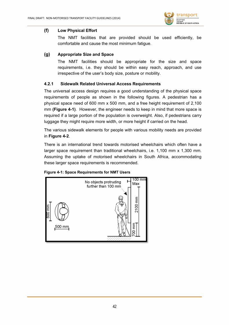
FINAL DRAFT: NON‐MOTORISED TRANSPORT FACILITY GUIDELINES (2014)
42
(f) Low Physical Effort
The NMT facilities that are provided should be used efficiently, be comfortable and cause the most minimum fatigue.
(g) Appropriate Size and Space
The NMT facilities should be appropriate for the size and space requirements, i.e. they should be within easy reach, approach, and use irrespective of the user’s body size, posture or mobility.
Sidewalk Related Universal Access Requirements 4.2.1
The universal access design requires a good understanding of the physical space
requirements of people as shown in the following figures. A pedestrian has a
physical space need of 600 mm x 500 mm, and a free height requirement of 2,100
mm (Figure 4-1). However, the engineer needs to keep in mind that more space is
required if a large portion of the population is overweight. Also, if pedestrians carry
luggage they might require more width, or more height if carried on the head.
The various sidewalk elements for people with various mobility needs are provided
in Figure 4-2.
There is an international trend towards motorised wheelchairs which often have a
larger space requirement than traditional wheelchairs, i.e. 1,100 mm x 1,300 mm.
Assuming the uptake of motorised wheelchairs in South Africa, accommodating
these larger space requirements is recommended.
Figure 4-1: Space Requirements for NMT Users
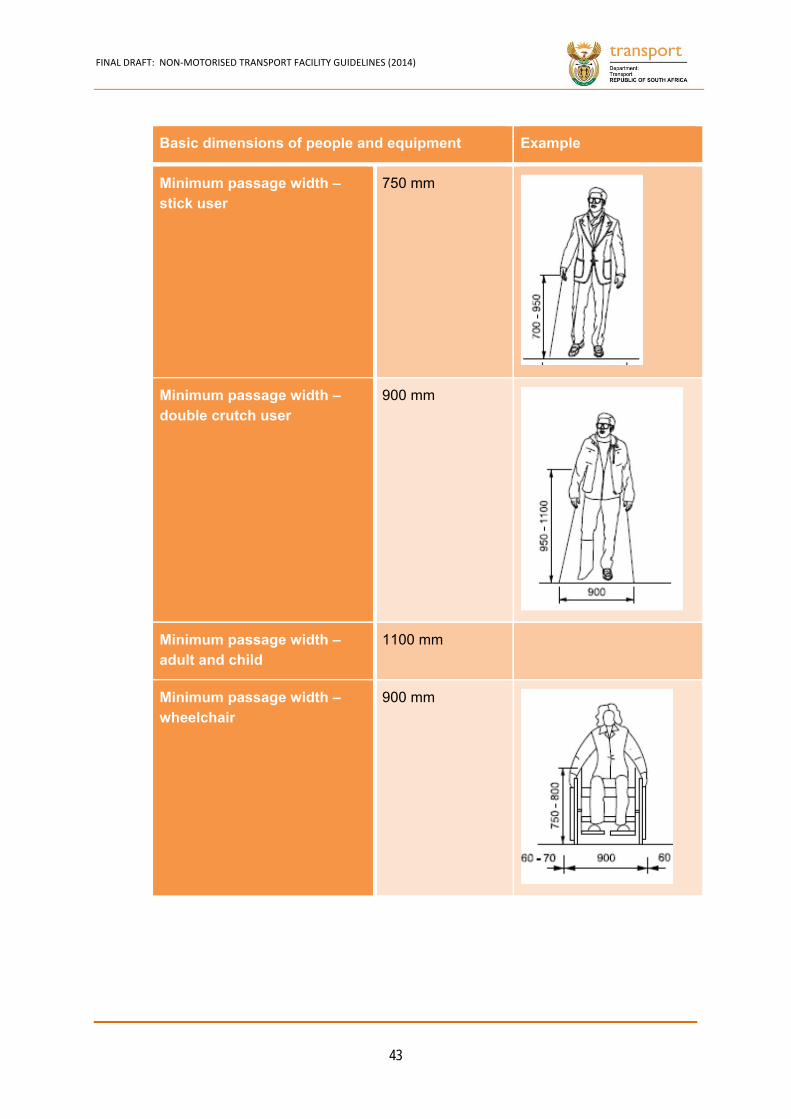
FINAL DRAFT: NON‐MOTORISED TRANSPORT FACILITY GUIDELINES (2014)
43
Basic dimensions of people and equipment Example
Minimum passage width – stick user
750 mm
Minimum passage width – double crutch user
900 mm
Minimum passage width – adult and child
1100 mm
Minimum passage width – wheelchair
900 mm
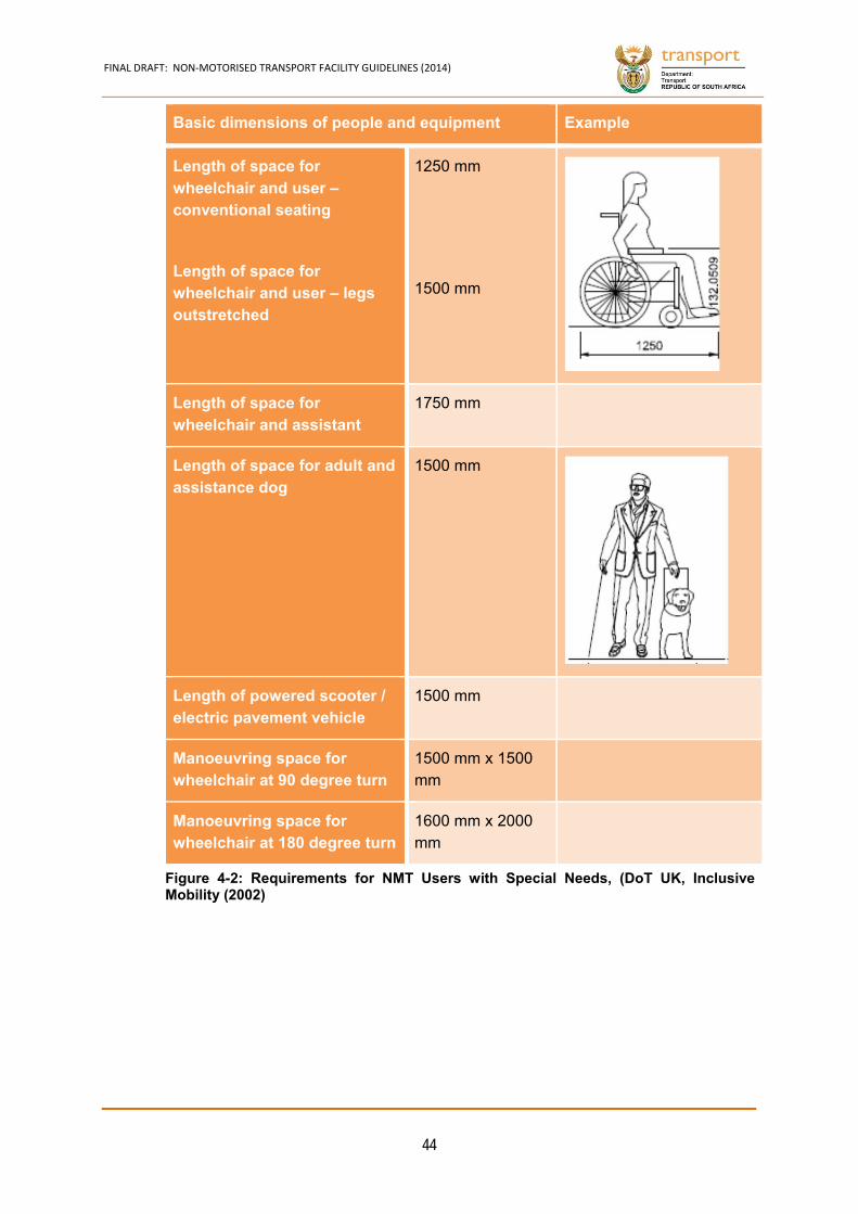
FINAL DRAFT: NON‐MOTORISED TRANSPORT FACILITY GUIDELINES (2014)
44
Basic dimensions of people and equipment Example
Length of space for wheelchair and user – conventional seating
Length of space for wheelchair and user – legs outstretched
1250 mm
1500 mm
Length of space for wheelchair and assistant
1750 mm
Length of space for adult and assistance dog
1500 mm
Length of powered scooter / electric pavement vehicle
1500 mm
Manoeuvring space for wheelchair at 90 degree turn
1500 mm x 1500 mm
Manoeuvring space for wheelchair at 180 degree turn
1600 mm x 2000 mm
Figure 4-2: Requirements for NMT Users with Special Needs, (DoT UK, InclusiveMobility (2002)

FINAL DRAFT: NON‐MOTORISED TRANSPORT FACILITY GUIDELINES (2014)
45
Universal Design Requirements for Bicycle Facilities 4.2.2
Universal design aspects related to bicycle facilities are the space requirements for
cyclists (height and width) that are shown in Figure 4-3 and Figure 4-4.
Extraordinary non-motorised transport, such as tricycles and bicycles with trailers,
has greater space requirements.
Lastly, there are extraordinary users of bicycle facilities, such as skateboard and
roller blade users. Although the movement of these users is different to bicycle
users, the space requirement is equal or less than the space requirement for
extraordinary bicycles.
Figure 4-3: Space Requirements for Bicycle Users
Figure 4-4: Space Requirements for Extraordinary Bicycle Users
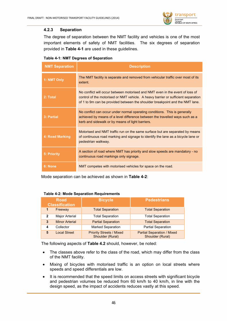
FINAL DRAFT: NON‐MOTORISED TRANSPORT FACILITY GUIDELINES (2014)
46
Separation 4.2.3
The degree of separation between the NMT facility and vehicles is one of the most
important elements of safety of NMT facilities. The six degrees of separation
provided in Table 4-1 are used in these guidelines.
NMT Separation Description
1: NMT Only The NMT facility is separate and removed from vehicular traffic over most of its
extent.
2: Total
No conflict will occur between motorised and NMT even in the event of loss of
control of the motorised or NMT vehicle. A heavy barrier or sufficient separation
of 1 to 9m can be provided between the shoulder breakpoint and the NMT lane.
3: Partial
No conflict can occur under normal operating conditions. This is generally
achieved by means of a level difference between the travelled ways such as a
kerb and sidewalk or by means of light barriers.
4: Road Marking
Motorised and NMT traffic run on the same surface but are separated by means
of continuous road marking and signage to identify the lane as a bicycle lane or
pedestrian walkway.
5: Priority A section of road where NMT has priority and slow speeds are mandatory - no
continuous road markings only signage.
6: None NMT competes with motorised vehicles for space on the road.
Mode separation can be achieved as shown in Table 4-2:
Road Classification
Bicycle Pedestrians
1 Freeway Total Separation Total Separation
2 Major Arterial Total Separation Total Separation
3 Minor Arterial Partial Separation Total Separation
4 Collector Marked Separation Partial Separation
5 Local Street Priority Streets / Mixed Shoulder (Rural)
Partial Separation / Mixed Shoulder (Rural)
The following aspects of Table 4.2 should, however, be noted:
The classes above refer to the class of the road, which may differ from the class of the NMT facility.
Mixing of bicycles with motorised traffic is an option on local streets where speeds and speed differentials are low.
It is recommended that the speed limits on access streets with significant bicycle and pedestrian volumes be reduced from 60 km/h to 40 km/h, in line with the design speed, as the impact of accidents reduces vastly at this speed.
Table 4-1: NMT Degrees of Separation
Table 4-2: Mode Separation Requirements
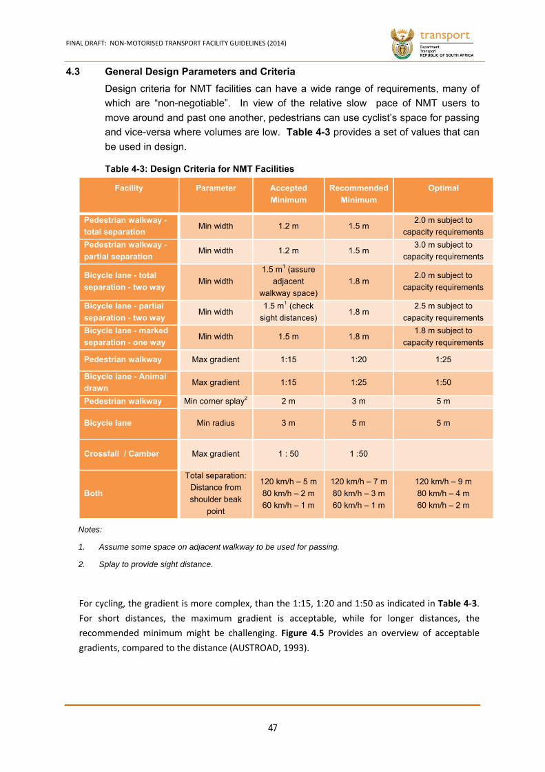
FINAL DRAFT: NON‐MOTORISED TRANSPORT FACILITY GUIDELINES (2014)
47
4.3 General Design Parameters and Criteria
Design criteria for NMT facilities can have a wide range of requirements, many of
which are “non-negotiable”. In view of the relative slow pace of NMT users to
move around and past one another, pedestrians can use cyclist’s space for passing
and vice-versa where volumes are low. Table 4-3 provides a set of values that can
be used in design.
Facility Parameter Accepted
Minimum
Recommended
Minimum
Optimal
Pedestrian walkway -
total separation Min width 1.2 m 1.5 m
2.0 m subject to
capacity requirements
Pedestrian walkway -
partial separation Min width 1.2 m 1.5 m
3.0 m subject to
capacity requirements
Bicycle lane - total
separation - two way Min width
1.5 m1 (assure
adjacent
walkway space)
1.8 m 2.0 m subject to
capacity requirements
Bicycle lane - partial
separation - two way Min width
1.5 m1 (check
sight distances) 1.8 m
2.5 m subject to
capacity requirements
Bicycle lane - marked
separation - one way Min width 1.5 m 1.8 m
1.8 m subject to
capacity requirements
Pedestrian walkway Max gradient 1:15 1:20 1:25
Bicycle lane - Animal
drawn Max gradient 1:15 1:25 1:50
Pedestrian walkway Min corner splay2 2 m 3 m 5 m
Bicycle lane Min radius 3 m 5 m 5 m
Crossfall / Camber Max gradient 1 : 50 1 :50
Both
Total separation:
Distance from
shoulder beak
point
120 km/h – 5 m
80 km/h – 2 m
60 km/h – 1 m
120 km/h – 7 m
80 km/h – 3 m
60 km/h – 1 m
120 km/h – 9 m
80 km/h – 4 m
60 km/h – 2 m
Notes:
1. Assume some space on adjacent walkway to be used for passing.
2. Splay to provide sight distance.
For cycling, the gradient is more complex, than the 1:15, 1:20 and 1:50 as indicated in Table 4‐3.
For short distances, the maximum gradient is acceptable, while for longer distances, the
recommended minimum might be challenging. Figure 4.5 Provides an overview of acceptable
gradients, compared to the distance (AUSTROAD, 1993).
Table 4-3: Design Criteria for NMT Facilities
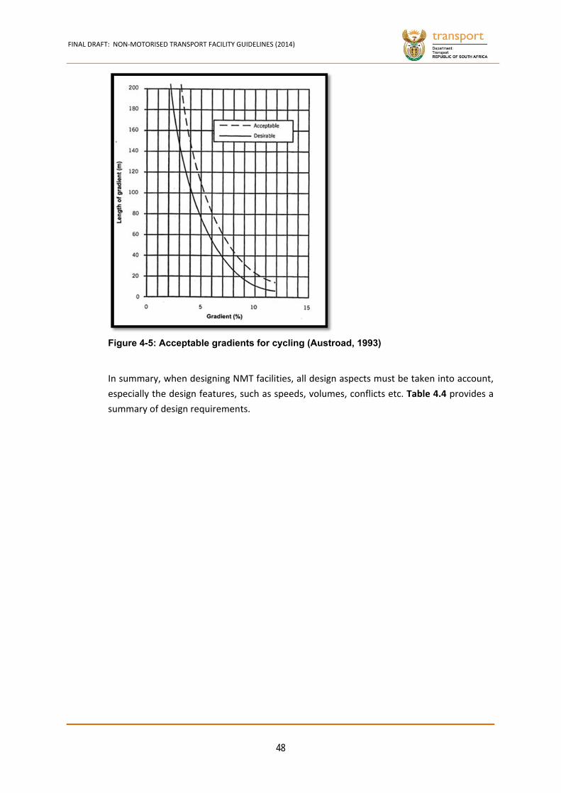
FINAL DRAFT: NON‐MOTORISED TRANSPORT FACILITY GUIDELINES (2014)
48
In summary, when designing NMT facilities, all design aspects must be taken into account,
especially the design features, such as speeds, volumes, conflicts etc. Table 4.4 provides a
summary of design requirements.
Figure 4-5: Acceptable gradients for cycling (Austroad, 1993)
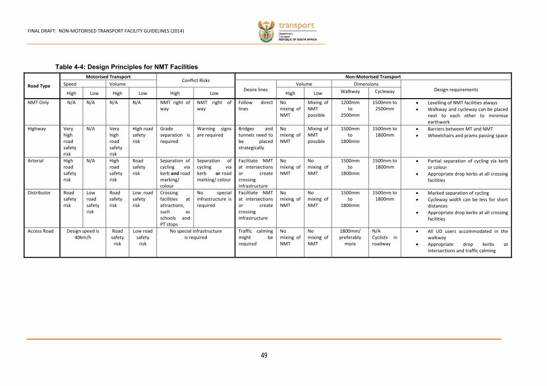
FINAL DRAFT: NON‐MOTORISED TRANSPORT FACILITY GUIDELINES (2014)
49
Road Type
Motorised Transport Conflict Risks
Non‐Motorised Transport
Speed Volume Desire lines
Volume DimensionsDesign requirements
High Low High Low High Low High Low Walkway Cycleway
NMT Only N/A N/A N/A N/A NMT right of way
NMT right of way
Follow direct lines
No mixing of NMT
Mixing of NMT possible
1200mmto
2500mm
1500mm to 2500mm
Levelling of NMT facilities always
Walkway and cycleway can be placed next to each other to minimise earthwork
Highway Very high road safety risk
N/A Very high road safety risk
High road safety risk
Grade separation is required
Warning signs are required
Bridges and tunnels need to be placed strategically
No mixing of NMT
Mixing of NMT possible
1500mmto
1800mm
1500mm to 1800mm
Barriers between MT and NMT
Wheelchairs and prams passing space
Arterial High road safety risk
N/A High road safety risk
Road safety risk
Separation of cycling via kerb and road marking/ colour
Separation of cycling via kerb or road marking/ colour
Facilitate NMT at intersections or create crossing infrastructure
No mixing of NMT
No mixing of NMT
1500mmto
1800mm
1500mm to 1800mm
Partial separation of cycling via kerb or colour
Appropriate drop kerbs at all crossing facilities
Distributor Road safety risk
Low road safety risk
Road safety risk
Low road safety risk
Crossing facilities at attractions, such as schools and PT stops
No special infrastructure is required
Facilitate NMT at intersections or create crossing infrastructure
No mixing of NMT
No mixing of NMT
1500mmto
1800mm
1500mm to 1800mm
Marked separation of cycling
Cycleway width can be less for short distances
Appropriate drop kerbs at all crossing facilities
Access Road Design speed is 40km/h
Road safety risk
Low road safety risk
No special infrastructureis required
Traffic calming might be required
No mixing of NMT
No mixing of NMT
1800mm/ preferably
more
N/ACyclists in roadway
All UD users accommodated in the walkway
Appropriate drop kerbs at intersections and traffic calming
Table 4-4: Design Principles for NMT Facilities
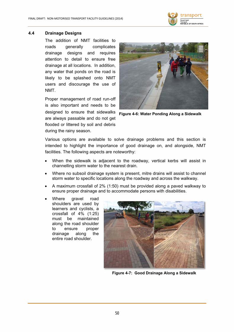
FINAL DRAFT: NON‐MOTORISED TRANSPORT FACILITY GUIDELINES (2014)
50
4.4 Drainage Designs
The addition of NMT facilities to
roads generally complicates
drainage designs and requires
attention to detail to ensure free
drainage at all locations. In addition,
any water that ponds on the road is
likely to be splashed onto NMT
users and discourage the use of
NMT.
Proper management of road run-off
is also important and needs to be
designed to ensure that sidewalks
are always passable and do not get
flooded or littered by soil and debris
during the rainy season.
Various options are available to solve drainage problems and this section is
intended to highlight the importance of good drainage on, and alongside, NMT
facilities. The following aspects are noteworthy:
When the sidewalk is adjacent to the roadway, vertical kerbs will assist in channelling storm water to the nearest drain.
Where no subsoil drainage system is present, mitre drains will assist to channel storm water to specific locations along the roadway and across the walkway.
A maximum crossfall of 2% (1:50) must be provided along a paved walkway to ensure proper drainage and to accommodate persons with disabilities.
Where gravel road shoulders are used by learners and cyclists, a crossfall of 4% (1:25) must be maintained along the road shoulder to ensure proper drainage along the entire road shoulder.
Figure 4-6: Water Ponding Along a Sidewalk
Figure 4-7: Good Drainage Along a Sidewalk

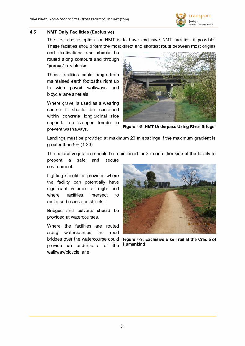
FINAL DRAFT: NON‐MOTORISED TRANSPORT FACILITY GUIDELINES (2014)
51
4.5 NMT Only Facilities (Exclusive)
The first choice option for NMT is to have exclusive NMT facilities if possible.
These facilities should form the most direct and shortest route between most origins
and destinations and should be
routed along contours and through
“porous” city blocks.
These facilities could range from
maintained earth footpaths right up
to wide paved walkways and
bicycle lane arterials.
Where gravel is used as a wearing
course it should be contained
within concrete longitudinal side
supports on steeper terrain to
prevent washaways.
Landings must be provided at maximum 20 m spacings if the maximum gradient is
greater than 5% (1:20).
The natural vegetation should be maintained for 3 m on either side of the facility to
present a safe and secure
environment.
Lighting should be provided where
the facility can potentially have
significant volumes at night and
where facilities intersect to
motorised roads and streets.
Bridges and culverts should be
provided at watercourses.
Where the facilities are routed
along watercourses the road
bridges over the watercourse could
provide an underpass for the
walkway/bicycle lane.
Figure 4-8: NMT Underpass Using River Bridge
Figure 4-9: Exclusive Bike Trail at the Cradle of Humankind
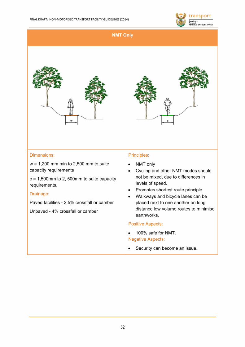
FINAL DRAFT: NON‐MOTORISED TRANSPORT FACILITY GUIDELINES (2014)
52
NMT Only
Dimensions:
w = 1,200 mm min to 2,500 mm to suite capacity requirements
c = 1,500mm to 2, 500mm to suite capacity requirements.
Drainage:
Paved facilities - 2.5% crossfall or camber
Unpaved - 4% crossfall or camber
Principles:
NMT only
Cycling and other NMT modes should not be mixed, due to differences in levels of speed.
Promotes shortest route principle
Walkways and bicycle lanes can be placed next to one another on long distance low volume routes to minimise earthworks.
Positive Aspects:
100% safe for NMT. Negative Aspects:
Security can become an issue.
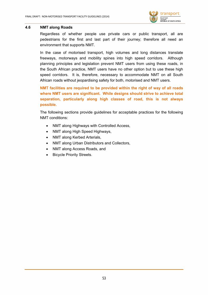
FINAL DRAFT: NON‐MOTORISED TRANSPORT FACILITY GUIDELINES (2014)
53
4.6 NMT along Roads
Regardless of whether people use private cars or public transport, all are
pedestrians for the first and last part of their journey; therefore all need an
environment that supports NMT.
In the case of motorised transport, high volumes and long distances translate
freeways, motorways and mobility spines into high speed corridors. Although
planning principles and legislation prevent NMT users from using these roads, in
the South African practice, NMT users have no other option but to use these high
speed corridors. It is, therefore, necessary to accommodate NMT on all South
African roads without jeopardising safety for both, motorised and NMT users.
NMT facilities are required to be provided within the right of way of all roads
where NMT users are significant. While designs should strive to achieve total
separation, particularly along high classes of road, this is not always
possible.
The following sections provide guidelines for acceptable practices for the following
NMT conditions:
NMT along Highways with Controlled Access,
NMT along High Speed Highways,
NMT along Kerbed Arterials,
NMT along Urban Distributors and Collectors,
NMT along Access Roads, and
Bicycle Priority Streets.
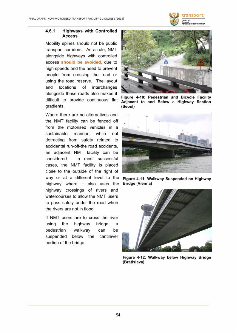
FINAL DRAFT: NON‐MOTORISED TRANSPORT FACILITY GUIDELINES (2014)
54
Highways with Controlled 4.6.1Access
Mobility spines should not be public
transport corridors. As a rule, NMT
alongside highways with controlled
access should be avoided, due to
high speeds and the need to prevent
people from crossing the road or
using the road reserve. The layout
and locations of interchanges
alongside these roads also makes it
difficult to provide continuous flat
gradients.
Where there are no alternatives and
the NMT facility can be fenced off
from the motorised vehicles in a
sustainable manner, while not
detracting from safety related to
accidental run-off-the road accidents,
an adjacent NMT facility can be
considered. In most successful
cases, the NMT facility is placed
close to the outside of the right of
way or at a different level to the
highway where it also uses the
highway crossings of rivers and
watercourses to allow the NMT users
to pass safely under the road when
the rivers are not in flood.
If NMT users are to cross the river
using the highway bridge, a
pedestrian walkway can be
suspended below the cantilever
portion of the bridge.
Figure 4-11: Walkway Suspended on HighwayBridge (Vienna)
Figure 4-10: Pedestrian and Bicycle FacilityAdjacent to and Below a Highway Section(Seoul)
Figure 4-12: Walkway below Highway Bridge(Bratislava)
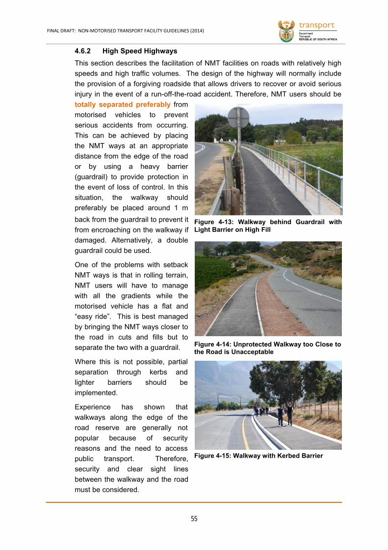
FINAL DRAFT: NON‐MOTORISED TRANSPORT FACILITY GUIDELINES (2014)
55
High Speed Highways 4.6.2
This section describes the facilitation of NMT facilities on roads with relatively high
speeds and high traffic volumes. The design of the highway will normally include
the provision of a forgiving roadside that allows drivers to recover or avoid serious
injury in the event of a run-off-the-road accident. Therefore, NMT users should be
totally separated preferably from
motorised vehicles to prevent
serious accidents from occurring.
This can be achieved by placing
the NMT ways at an appropriate
distance from the edge of the road
or by using a heavy barrier
(guardrail) to provide protection in
the event of loss of control. In this
situation, the walkway should
preferably be placed around 1 m
back from the guardrail to prevent it
from encroaching on the walkway if
damaged. Alternatively, a double
guardrail could be used.
One of the problems with setback
NMT ways is that in rolling terrain,
NMT users will have to manage
with all the gradients while the
motorised vehicle has a flat and
“easy ride”. This is best managed
by bringing the NMT ways closer to
the road in cuts and fills but to
separate the two with a guardrail.
Where this is not possible, partial
separation through kerbs and
lighter barriers should be
implemented.
Experience has shown that
walkways along the edge of the
road reserve are generally not
popular because of security
reasons and the need to access
public transport. Therefore,
security and clear sight lines
between the walkway and the road
must be considered.
Figure 4-13: Walkway behind Guardrail withLight Barrier on High Fill
Figure 4-15: Walkway with Kerbed Barrier
Figure 4-14: Unprotected Walkway too Close tothe Road is Unacceptable

FINAL DRAFT: NON‐MOTORISED TRANSPORT FACILITY GUIDELINES (2014)
56
High Speed Highways
Dimensions:
a = varies
w = 1,800 mm (Min: 1,500 mm)
c = 1,800 mm (Min: 1,500 mm)
v = varies – if no barrier, then > 2 m for 60 km/h
and > 9 m for 120 km/h
s = varies
l = typically 3,400 to 3,700 mm
i = typically 2%
d = typically 3,810 mm
h = typically 530 mm
Principles:
Total separation
Width should ideally accommodate two persons with wheelchairs/ prams.
Positive Aspects:
Complete safety is guaranteed. Negative Aspects:
Wide road reserve
Remarks: Source:
COTO, 2012
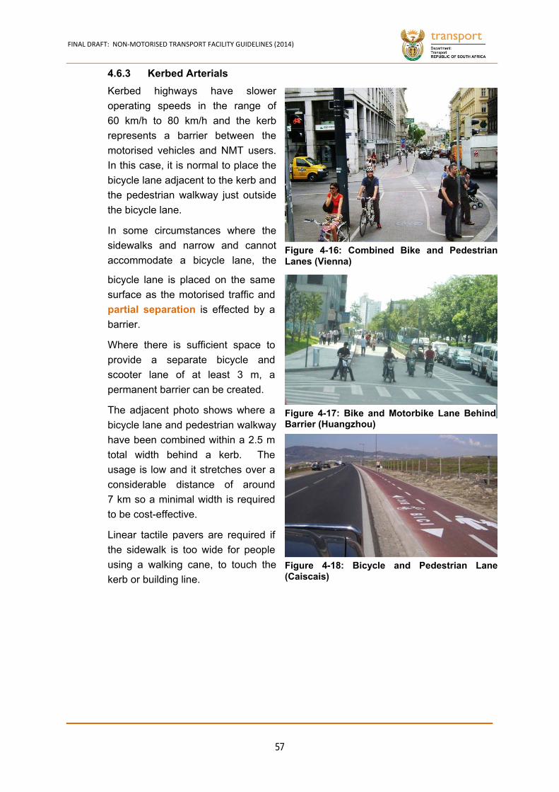
FINAL DRAFT: NON‐MOTORISED TRANSPORT FACILITY GUIDELINES (2014)
57
Kerbed Arterials 4.6.3
Kerbed highways have slower
operating speeds in the range of
60 km/h to 80 km/h and the kerb
represents a barrier between the
motorised vehicles and NMT users.
In this case, it is normal to place the
bicycle lane adjacent to the kerb and
the pedestrian walkway just outside
the bicycle lane.
In some circumstances where the
sidewalks and narrow and cannot
accommodate a bicycle lane, the
bicycle lane is placed on the same
surface as the motorised traffic and
partial separation is effected by a
barrier.
Where there is sufficient space to
provide a separate bicycle and
scooter lane of at least 3 m, a
permanent barrier can be created.
The adjacent photo shows where a
bicycle lane and pedestrian walkway
have been combined within a 2.5 m
total width behind a kerb. The
usage is low and it stretches over a
considerable distance of around
7 km so a minimal width is required
to be cost-effective.
Linear tactile pavers are required if
the sidewalk is too wide for people
using a walking cane, to touch the
kerb or building line.
Figure 4-16: Combined Bike and PedestrianLanes (Vienna)
Figure 4-17: Bike and Motorbike Lane Behind Barrier (Huangzhou)
Figure 4-18: Bicycle and Pedestrian Lane(Caiscais)
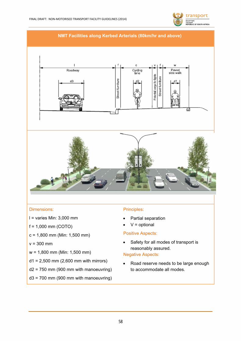
FINAL DRAFT: NON‐MOTORISED TRANSPORT FACILITY GUIDELINES (2014)
58
NMT Facilities along Kerbed Arterials (80km/hr and above)
Dimensions:
l = varies Min: 3,000 mm
f = 1,000 mm (COTO)
c = 1,800 mm (Min: 1,500 mm)
v = 300 mm
w = 1,800 mm (Min: 1,500 mm)
d1 = 2,500 mm (2,600 mm with mirrors)
d2 = 750 mm (900 mm with manoeuvring)
d3 = 700 mm (900 mm with manoeuvring)
Principles:
Partial separation
V = optional
Positive Aspects:
Safety for all modes of transport is reasonably assured.
Negative Aspects:
Road reserve needs to be large enough to accommodate all modes.

FINAL DRAFT: NON‐MOTORISED TRANSPORT FACILITY GUIDELINES (2014)
59
Urban Distributors and Collectors (60 km/h) 4.6.4
On urban collector with bicycle lanes,
the bicycle lane is placed on the road
surface and is only separated by road
markings and signage.
Urban distributors and collectors are
designed to provide access to urban
settlements/suburbs. They connect
the accessibility spaces with the
mobility network. Their emphasis
should be on connectivity and not
throughput. Urban distributors and
collectors have a design speed of
60 km/h. If these roads have one
lane per direction, the bicycle lane
can be placed on the road surface
and only separated by road markings
and signage. If there is insufficient
road space, road diets can be
considered
(See Figure 4-20).
Although many residents and the
retail industry in general are against
road diets during the planning phase,
research shows that if turnover and
liveability are influenced positively,
then motorised transport road
allocation can be reduced.
Linear tactile pavers are required if
the sidewalk is too wide for people
using walking canes, to assist people
not to touch the kerb or building line.
Figure 4-19: Urban Collector with Bicycle Lane(Portland USA)
Figure 4-20: Road Diet Example
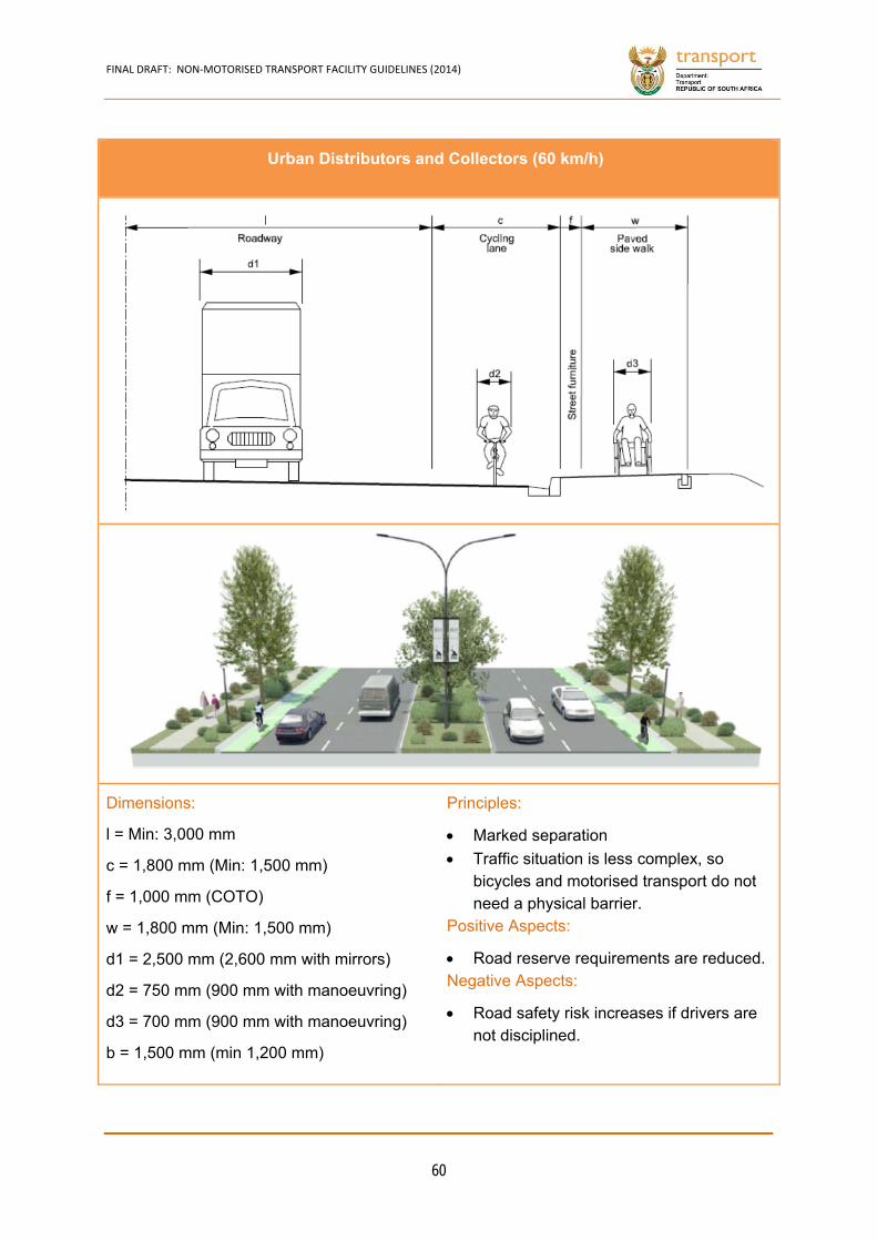
FINAL DRAFT: NON‐MOTORISED TRANSPORT FACILITY GUIDELINES (2014)
60
Urban Distributors and Collectors (60 km/h)
Dimensions:
l = Min: 3,000 mm
c = 1,800 mm (Min: 1,500 mm)
f = 1,000 mm (COTO)
w = 1,800 mm (Min: 1,500 mm)
d1 = 2,500 mm (2,600 mm with mirrors)
d2 = 750 mm (900 mm with manoeuvring)
d3 = 700 mm (900 mm with manoeuvring)
b = 1,500 mm (min 1,200 mm)
Principles:
Marked separation
Traffic situation is less complex, so bicycles and motorised transport do not need a physical barrier.
Positive Aspects:
Road reserve requirements are reduced. Negative Aspects:
Road safety risk increases if drivers are not disciplined.
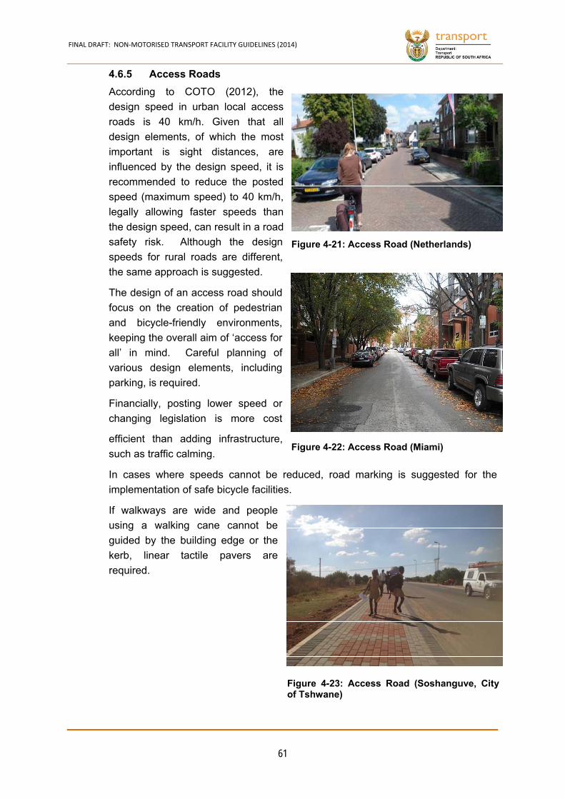
FINAL DRAFT: NON‐MOTORISED TRANSPORT FACILITY GUIDELINES (2014)
61
Access Roads 4.6.5
According to COTO (2012), the
design speed in urban local access
roads is 40 km/h. Given that all
design elements, of which the most
important is sight distances, are
influenced by the design speed, it is
recommended to reduce the posted
speed (maximum speed) to 40 km/h,
legally allowing faster speeds than
the design speed, can result in a road
safety risk. Although the design
speeds for rural roads are different,
the same approach is suggested.
The design of an access road should
focus on the creation of pedestrian
and bicycle-friendly environments,
keeping the overall aim of ‘access for
all’ in mind. Careful planning of
various design elements, including
parking, is required.
Financially, posting lower speed or
changing legislation is more cost
efficient than adding infrastructure,
such as traffic calming.
In cases where speeds cannot be reduced, road marking is suggested for the
implementation of safe bicycle facilities.
If walkways are wide and people
using a walking cane cannot be
guided by the building edge or the
kerb, linear tactile pavers are
required.
Figure 4-21: Access Road (Netherlands)
Figure 4-22: Access Road (Miami)
Figure 4-23: Access Road (Soshanguve, Cityof Tshwane)
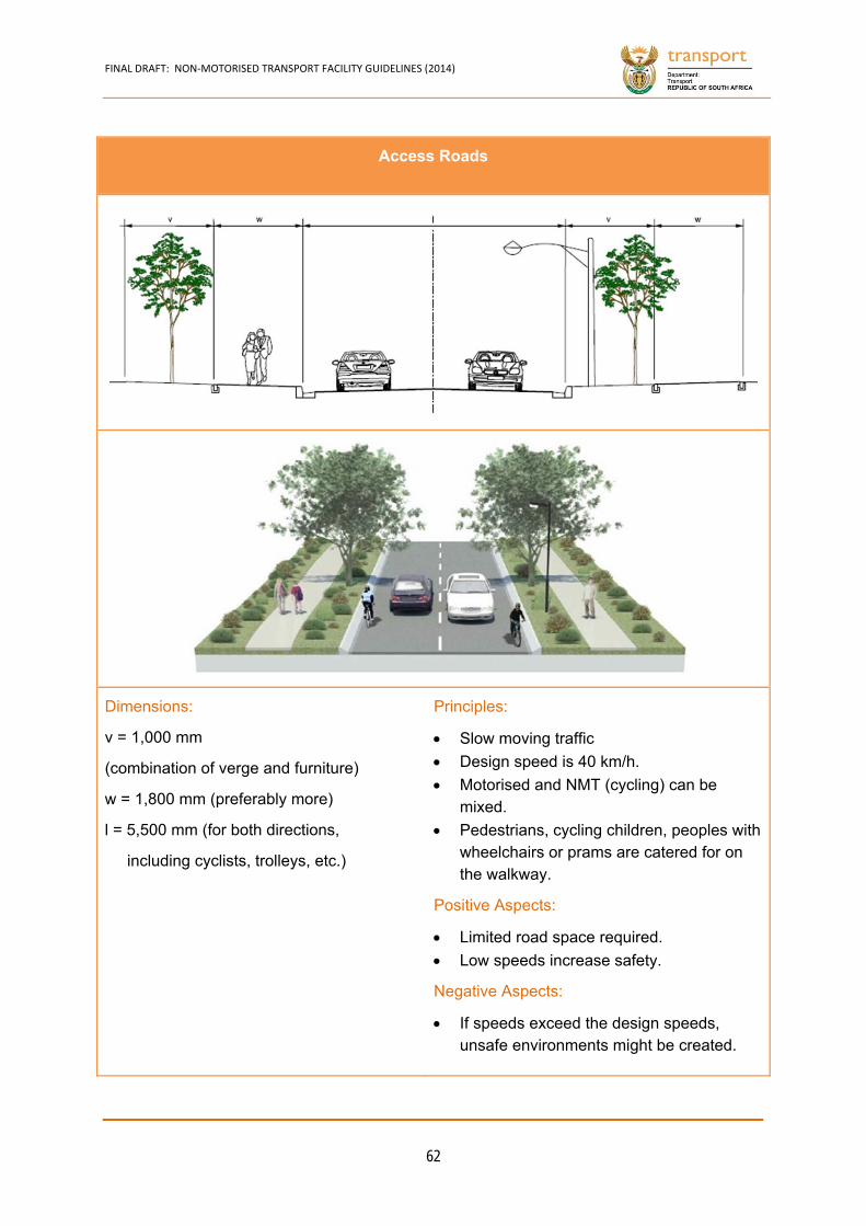
FINAL DRAFT: NON‐MOTORISED TRANSPORT FACILITY GUIDELINES (2014)
62
Access Roads
Dimensions:
v = 1,000 mm
(combination of verge and furniture)
w = 1,800 mm (preferably more)
l = 5,500 mm (for both directions,
including cyclists, trolleys, etc.)
Principles:
Slow moving traffic
Design speed is 40 km/h.
Motorised and NMT (cycling) can be mixed.
Pedestrians, cycling children, peoples with wheelchairs or prams are catered for on the walkway.
Positive Aspects:
Limited road space required.
Low speeds increase safety.
Negative Aspects:
If speeds exceed the design speeds, unsafe environments might be created.
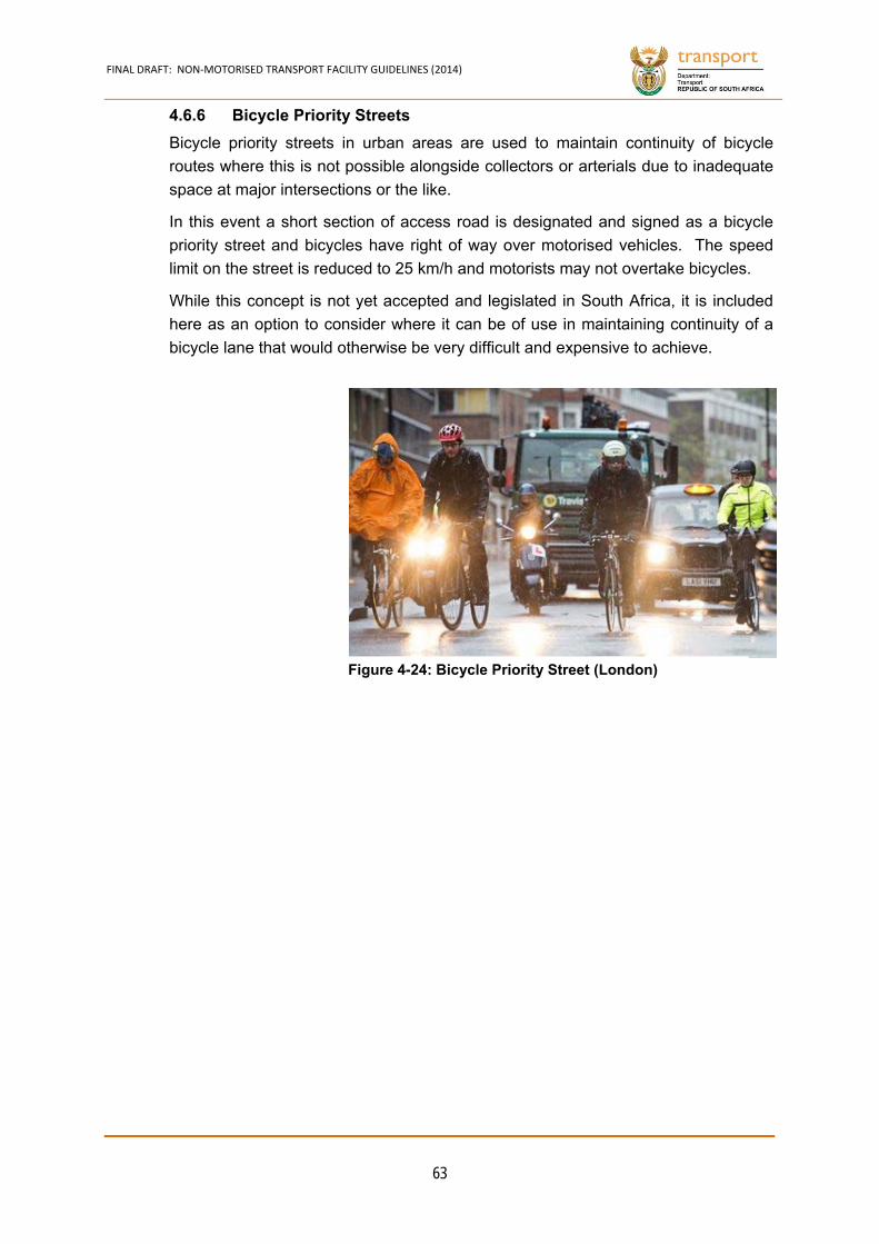
FINAL DRAFT: NON‐MOTORISED TRANSPORT FACILITY GUIDELINES (2014)
63
Bicycle Priority Streets 4.6.6
Bicycle priority streets in urban areas are used to maintain continuity of bicycle
routes where this is not possible alongside collectors or arterials due to inadequate
space at major intersections or the like.
In this event a short section of access road is designated and signed as a bicycle
priority street and bicycles have right of way over motorised vehicles. The speed
limit on the street is reduced to 25 km/h and motorists may not overtake bicycles.
While this concept is not yet accepted and legislated in South Africa, it is included
here as an option to consider where it can be of use in maintaining continuity of a
bicycle lane that would otherwise be very difficult and expensive to achieve.
Figure 4-24: Bicycle Priority Street (London)
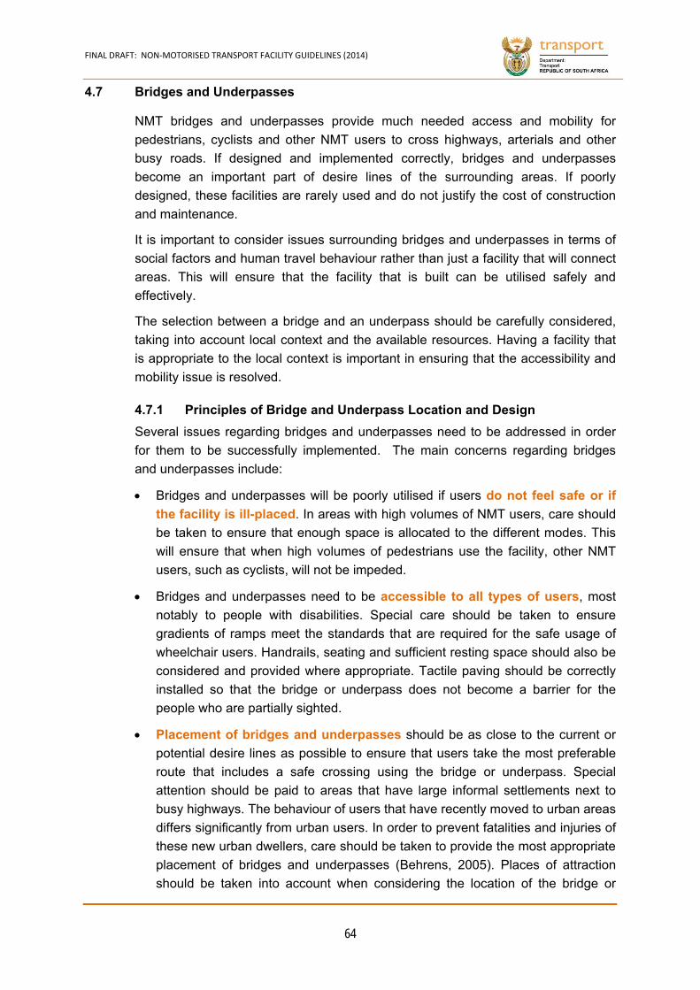
FINAL DRAFT: NON‐MOTORISED TRANSPORT FACILITY GUIDELINES (2014)
64
4.7 Bridges and Underpasses
NMT bridges and underpasses provide much needed access and mobility for
pedestrians, cyclists and other NMT users to cross highways, arterials and other
busy roads. If designed and implemented correctly, bridges and underpasses
become an important part of desire lines of the surrounding areas. If poorly
designed, these facilities are rarely used and do not justify the cost of construction
and maintenance.
It is important to consider issues surrounding bridges and underpasses in terms of
social factors and human travel behaviour rather than just a facility that will connect
areas. This will ensure that the facility that is built can be utilised safely and
effectively.
The selection between a bridge and an underpass should be carefully considered,
taking into account local context and the available resources. Having a facility that
is appropriate to the local context is important in ensuring that the accessibility and
mobility issue is resolved.
Principles of Bridge and Underpass Location and Design 4.7.1
Several issues regarding bridges and underpasses need to be addressed in order
for them to be successfully implemented. The main concerns regarding bridges
and underpasses include:
Bridges and underpasses will be poorly utilised if users do not feel safe or if
the facility is ill-placed. In areas with high volumes of NMT users, care should
be taken to ensure that enough space is allocated to the different modes. This
will ensure that when high volumes of pedestrians use the facility, other NMT
users, such as cyclists, will not be impeded.
Bridges and underpasses need to be accessible to all types of users, most
notably to people with disabilities. Special care should be taken to ensure
gradients of ramps meet the standards that are required for the safe usage of
wheelchair users. Handrails, seating and sufficient resting space should also be
considered and provided where appropriate. Tactile paving should be correctly
installed so that the bridge or underpass does not become a barrier for the
people who are partially sighted.
Placement of bridges and underpasses should be as close to the current or
potential desire lines as possible to ensure that users take the most preferable
route that includes a safe crossing using the bridge or underpass. Special
attention should be paid to areas that have large informal settlements next to
busy highways. The behaviour of users that have recently moved to urban areas
differs significantly from urban users. In order to prevent fatalities and injuries of
these new urban dwellers, care should be taken to provide the most appropriate
placement of bridges and underpasses (Behrens, 2005). Places of attraction
should be taken into account when considering the location of the bridge or
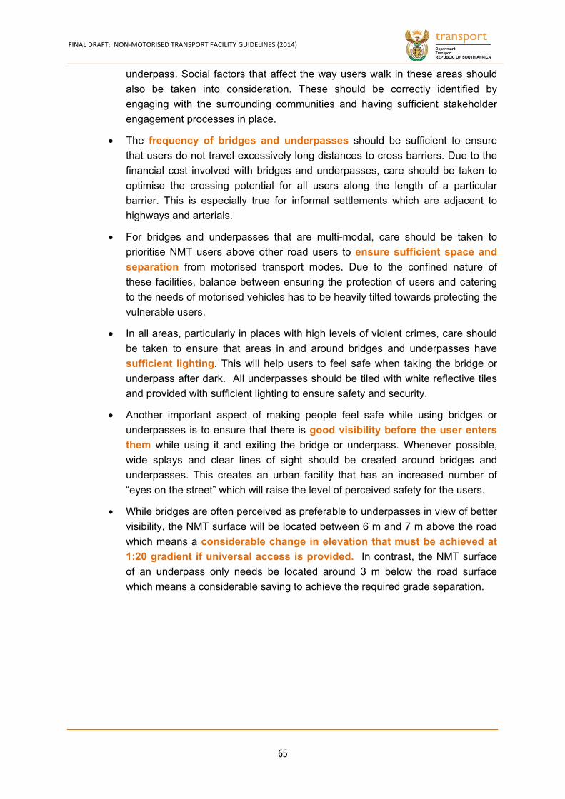
FINAL DRAFT: NON‐MOTORISED TRANSPORT FACILITY GUIDELINES (2014)
65
underpass. Social factors that affect the way users walk in these areas should
also be taken into consideration. These should be correctly identified by
engaging with the surrounding communities and having sufficient stakeholder
engagement processes in place.
The frequency of bridges and underpasses should be sufficient to ensure
that users do not travel excessively long distances to cross barriers. Due to the
financial cost involved with bridges and underpasses, care should be taken to
optimise the crossing potential for all users along the length of a particular
barrier. This is especially true for informal settlements which are adjacent to
highways and arterials.
For bridges and underpasses that are multi-modal, care should be taken to
prioritise NMT users above other road users to ensure sufficient space and
separation from motorised transport modes. Due to the confined nature of
these facilities, balance between ensuring the protection of users and catering
to the needs of motorised vehicles has to be heavily tilted towards protecting the
vulnerable users.
In all areas, particularly in places with high levels of violent crimes, care should
be taken to ensure that areas in and around bridges and underpasses have
sufficient lighting. This will help users to feel safe when taking the bridge or
underpass after dark. All underpasses should be tiled with white reflective tiles
and provided with sufficient lighting to ensure safety and security.
Another important aspect of making people feel safe while using bridges or
underpasses is to ensure that there is good visibility before the user enters
them while using it and exiting the bridge or underpass. Whenever possible,
wide splays and clear lines of sight should be created around bridges and
underpasses. This creates an urban facility that has an increased number of
“eyes on the street” which will raise the level of perceived safety for the users.
While bridges are often perceived as preferable to underpasses in view of better
visibility, the NMT surface will be located between 6 m and 7 m above the road
which means a considerable change in elevation that must be achieved at
In contrast, the NMT surface 1:20 gradient if universal access is provided.
of an underpass only needs be located around 3 m below the road surface
which means a considerable saving to achieve the required grade separation.

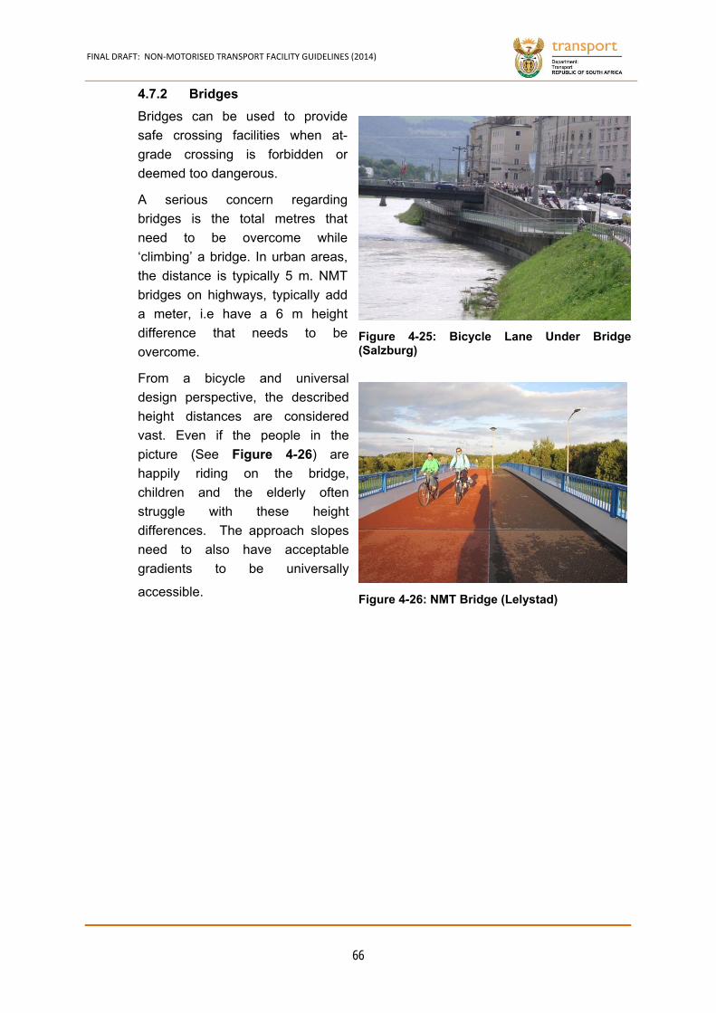
FINAL DRAFT: NON‐MOTORISED TRANSPORT FACILITY GUIDELINES (2014)
66
Bridges 4.7.2
Bridges can be used to provide
safe crossing facilities when at-
grade crossing is forbidden or
deemed too dangerous.
A serious concern regarding
bridges is the total metres that
need to be overcome while
‘climbing’ a bridge. In urban areas,
the distance is typically 5 m. NMT
bridges on highways, typically add
a meter, i.e have a 6 m height
difference that needs to be
overcome.
From a bicycle and universal
design perspective, the described
height distances are considered
vast. Even if the people in the
picture (See Figure 4-26) are
happily riding on the bridge,
children and the elderly often
struggle with these height
differences. The approach slopes
need to also have acceptable
gradients to be universally
accessible.
Figure 4-25: Bicycle Lane Under Bridge(Salzburg)
Figure 4-26: NMT Bridge (Lelystad)
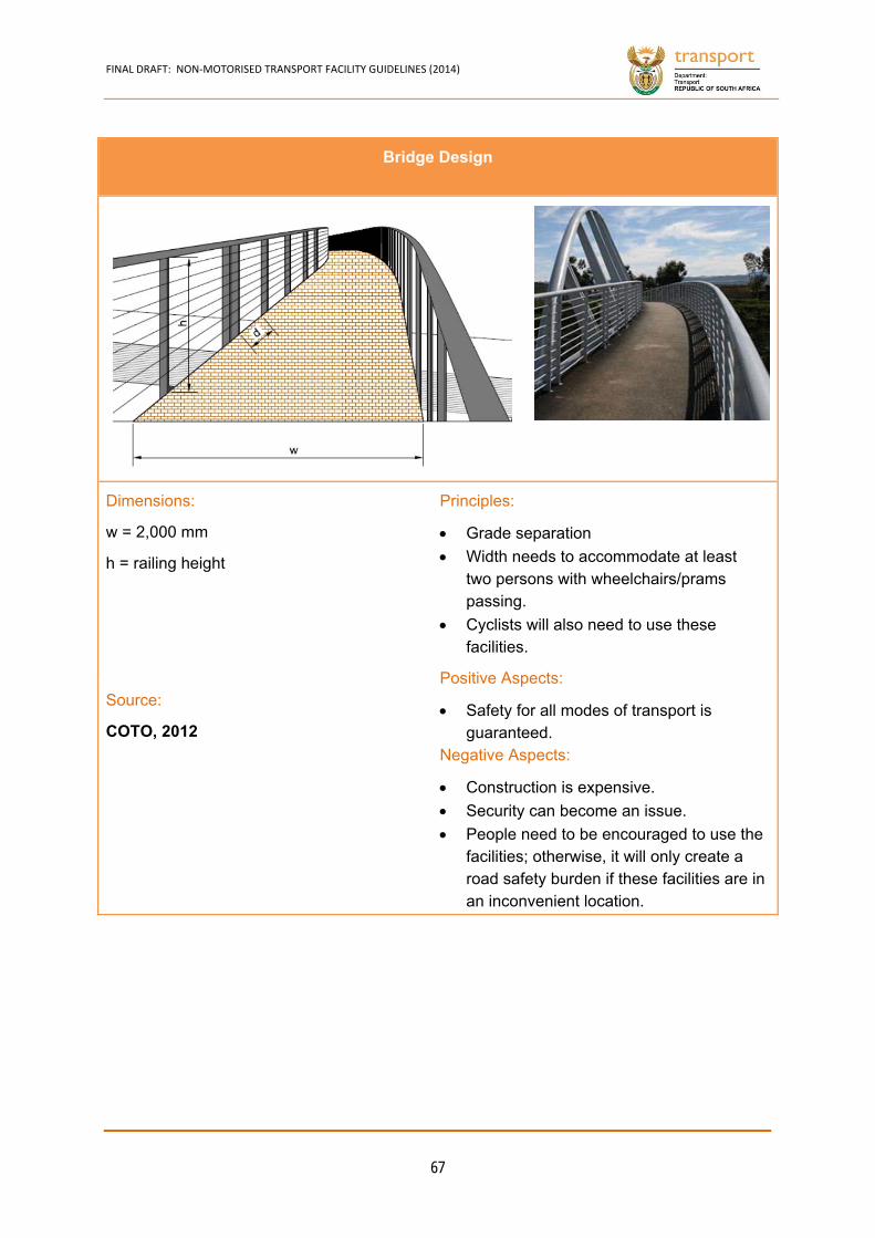
FINAL DRAFT: NON‐MOTORISED TRANSPORT FACILITY GUIDELINES (2014)
67
Bridge Design
Dimensions:
w = 2,000 mm
h = railing height
Principles:
Grade separation
Width needs to accommodate at least two persons with wheelchairs/prams passing.
Cyclists will also need to use these facilities.
Positive Aspects:
Safety for all modes of transport is guaranteed.
Negative Aspects:
Construction is expensive.
Security can become an issue.
People need to be encouraged to use the facilities; otherwise, it will only create a road safety burden if these facilities are in an inconvenient location.
Source:
COTO, 2012
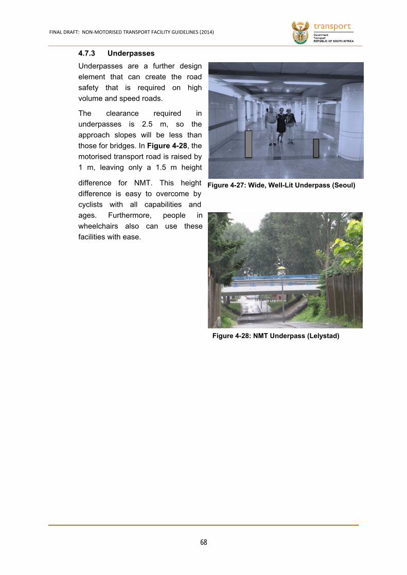
FINAL DRAFT: NON‐MOTORISED TRANSPORT FACILITY GUIDELINES (2014)
68
Underpasses 4.7.3
Underpasses are a further design
element that can create the road
safety that is required on high
volume and speed roads.
The clearance required in
underpasses is 2.5 m, so the
approach slopes will be less than
those for bridges. In Figure 4-28, the
motorised transport road is raised by
1 m, leaving only a 1.5 m height
difference for NMT. This height
difference is easy to overcome by
cyclists with all capabilities and
ages. Furthermore, people in
wheelchairs also can use these
facilities with ease.
Figure 4-27: Wide, Well-Lit Underpass (Seoul)
Figure 4-28: NMT Underpass (Lelystad)
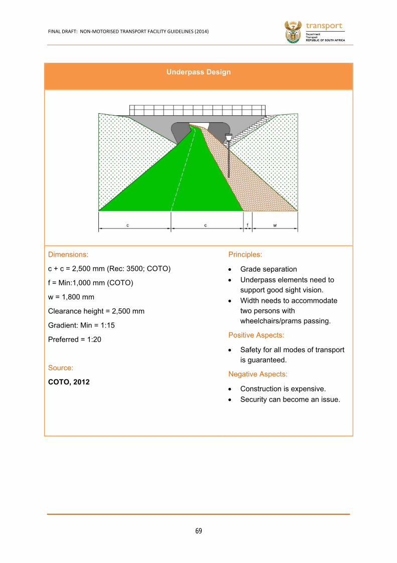
FINAL DRAFT: NON‐MOTORISED TRANSPORT FACILITY GUIDELINES (2014)
69
Underpass Design
Dimensions:
c + c = 2,500 mm (Rec: 3500; COTO)
f = Min:1,000 mm (COTO)
w = 1,800 mm
Clearance height = 2,500 mm
Gradient: Min = 1:15
Preferred = 1:20
Source:
COTO, 2012
Principles:
Grade separation
Underpass elements need to support good sight vision.
Width needs to accommodate two persons with wheelchairs/prams passing.
Positive Aspects:
Safety for all modes of transport is guaranteed.
Negative Aspects:
Construction is expensive.
Security can become an issue.

FINAL DRAFT: NON‐MOTORISED TRANSPORT FACILITY GUIDELINES (2014)
70
NMT River Bridges in Rural Areas 4.8.1
The use of narrow road
bridges on high speed
rural roads by
pedestrians without a
proper barrier as
specified in bridge
design manuals is
unacceptable and must
either be remedied
through widening and the
addition of a pedestrian
walkway or through the
construction of a
separate NMT bridge.
Furthermore, in rural areas, full
rivers often hinder learners from
accessing schools and many rural
communities are cut off from basic
socio-economic facilities and jobs.
Deliberate efforts have been
introduced through the Integrated
Rural Mobility and Access (IRMA)
programme of the Department of
Transport to link learners, and
rural communities in general, to
schools and other community
services during the rainy season.
A number of options are available
to safeguard rural persons across
road bridges and rivers as shown
in Figure 4-29.
Figure 4-29: Suspension Bridge Across the EsiphongweniRiver in KZN
Figure 4-30: Wading through Rivers due to Lack ofBridges

FINAL DRAFT: NON‐MOTORISED TRANSPORT FACILITY GUIDELINES (2014)
71
Road Bridges and Separate NMT Bridge Structures on Roads
Example of a separate NMT bridge structure next to the roadway
Dimensions:
Min width: 2 m
Min handrail height: 1 m with
vertical styles at min 100 mm
spacing
Principles:
Adjacent to Roads
Approaches to the NMT bridge structure must be the
same width as the bridge structure and flush with the
sidewalk.
Danger plates should be displayed on the road way for
vehicular traffic on both approaches to the structure.
General
Ramped access with gradient not more than 1:20 is
required to make these bridges accessible for all users.
Pedestrians and cyclists are sensitive to movement and
deflection of suspension bridge structures. The design
of the structure should therefore limit the amount of
deflection under a live load.
Entrances of these bridges must be designed to prevent
animals or motorcycles from entering the bridge
structure.
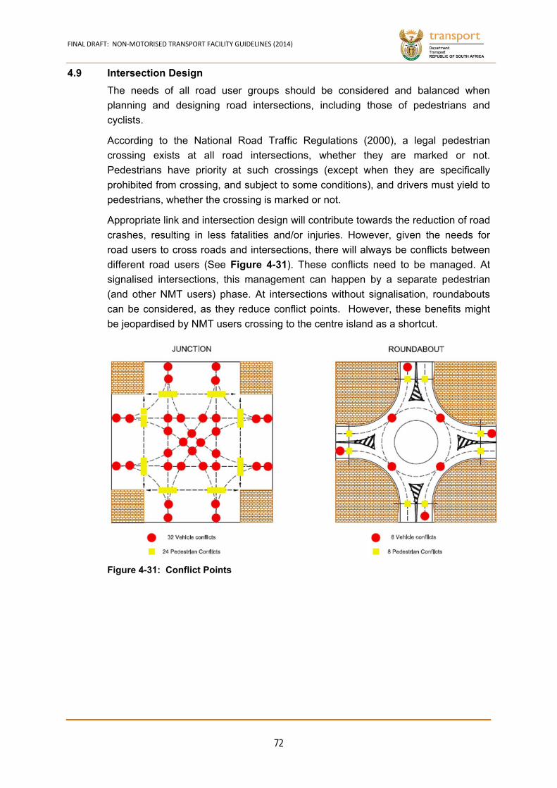
FINAL DRAFT: NON‐MOTORISED TRANSPORT FACILITY GUIDELINES (2014)
72
4.9 Intersection Design
The needs of all road user groups should be considered and balanced when
planning and designing road intersections, including those of pedestrians and
cyclists.
According to the National Road Traffic Regulations (2000), a legal pedestrian
crossing exists at all road intersections, whether they are marked or not.
Pedestrians have priority at such crossings (except when they are specifically
prohibited from crossing, and subject to some conditions), and drivers must yield to
pedestrians, whether the crossing is marked or not.
Appropriate link and intersection design will contribute towards the reduction of road
crashes, resulting in less fatalities and/or injuries. However, given the needs for
road users to cross roads and intersections, there will always be conflicts between
different road users (See Figure 4-31). These conflicts need to be managed. At
signalised intersections, this management can happen by a separate pedestrian
(and other NMT users) phase. At intersections without signalisation, roundabouts
can be considered, as they reduce conflict points. However, these benefits might
be jeopardised by NMT users crossing to the centre island as a shortcut.
Figure 4-31: Conflict Points


FINAL DRAFT: NON‐MOTORISED TRANSPORT FACILITY GUIDELINES (2014)
73
4.10 Pedestrian Crossing Facilities
Pedestrian crossings should be located within a natural path of travel, and wide
enough to accommodate the number of people using the facility. Crossings should
be located on the desire lines that would serve the majority of pedestrians.
Pedestrian crossings should not be located so near to other midblock crossings or
road intersections that drivers do not have sufficient time to react to the presence of
pedestrians. Drivers may need as much as 2.5 seconds to perceive and react to
hazards and dangers. Many drivers compound problems for themselves by driving
at speeds that are too fast for built-up areas. This can be a problem for freight
vehicles. Designs to limit speeds in areas with high densities are therefore
extremely important, as well as other means of speed restriction enforcement.
The separation distances given in Table 4-5 should be provided between
pedestrian crossings and other important elements of the road network that can
distract the attention of the driver. These include elements such as other midblock
crossings, road intersections, merge areas, bus and mini-bus stops, and the like.
Operating Speed or Speed Limit (km/h) Separation Distance (m)
20 15
30 20
40 30
50 35
60 45
Source: DOT, 2003
Having smaller radii, rather than larger ones, at intersections is better from a pedestrian view as these cut sight distances and force drivers to navigate corners at reduced speeds.
Table 4-5: Minimum Distances Between Crossings/Road Elements
Figure 4-32: Tight Radii Limits Desire Lines and Sight Distances
Source: Deven Country Council
Figure 4-33: Large Radii Increases Desire Lines and Sight Distances
Source: Deven Country Council
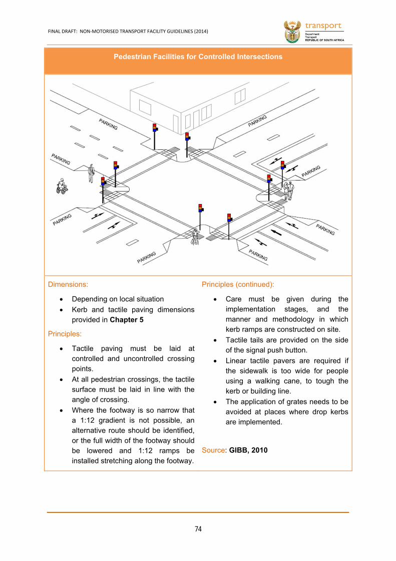
FINAL DRAFT: NON‐MOTORISED TRANSPORT FACILITY GUIDELINES (2014)
74
Pedestrian Facilities for Controlled Intersections
Dimensions:
Depending on local situation
Kerb and tactile paving dimensions provided in Chapter 5
Principles:
Tactile paving must be laid at controlled and uncontrolled crossing points.
At all pedestrian crossings, the tactile surface must be laid in line with the angle of crossing.
Where the footway is so narrow that a 1:12 gradient is not possible, an alternative route should be identified, or the full width of the footway should be lowered and 1:12 ramps be installed stretching along the footway.
Principles (continued):
Care must be given during the implementation stages, and the manner and methodology in which kerb ramps are constructed on site.
Tactile tails are provided on the side of the signal push button.
Linear tactile pavers are required if the sidewalk is too wide for people using a walking cane, to tough the kerb or building line.
The application of grates needs to be avoided at places where drop kerbs are implemented.
Source: GIBB, 2010
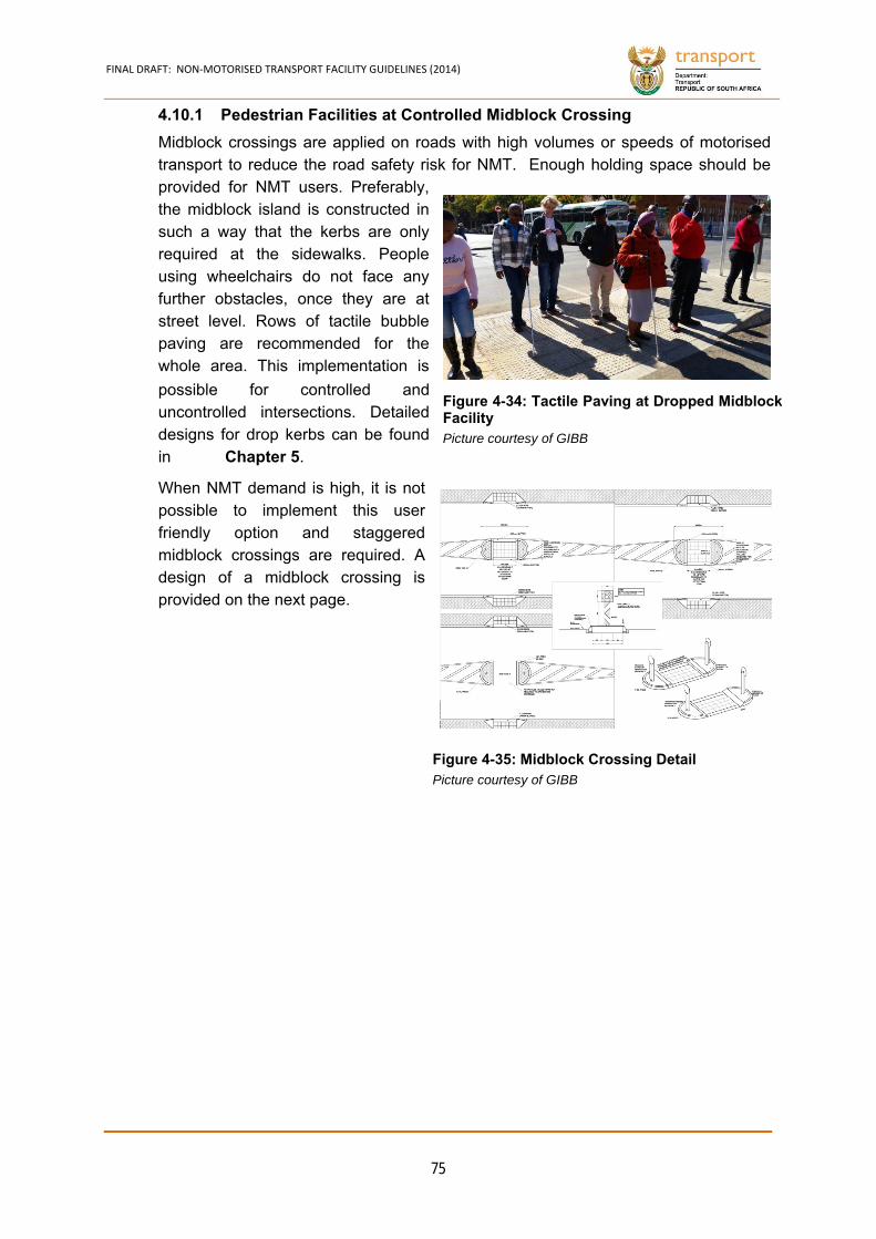
FINAL DRAFT: NON‐MOTORISED TRANSPORT FACILITY GUIDELINES (2014)
75
Figure 4-34: Tactile Paving at Dropped MidblockFacility Picture courtesy of GIBB
Figure 4-35: Midblock Crossing Detail Picture courtesy of GIBB
Pedestrian Facilities at Controlled Midblock Crossing 4.10.1
Midblock crossings are applied on roads with high volumes or speeds of motorised transport to reduce the road safety risk for NMT. Enough holding space should be provided for NMT users. Preferably, the midblock island is constructed in such a way that the kerbs are only required at the sidewalks. People using wheelchairs do not face any further obstacles, once they are at street level. Rows of tactile bubble paving are recommended for the whole area. This implementation is
possible for controlled and uncontrolled intersections. Detailed designs for drop kerbs can be found in Chapter 5.
When NMT demand is high, it is not possible to implement this user friendly option and staggered midblock crossings are required. A design of a midblock crossing is provided on the next page.

FINAL DRAFT: NON‐MOTORISED TRANSPORT FACILITY GUIDELINES (2014)
76
Pedestrian Facilities for Controlled Midblock Crossing
Dimensions:
Depending on local situation
Kerb and tactile paving dimensions provided in Chapter 5
Landing of 1,5m needs to be provided
Principles:
Staggered crossing layout does not follow pedestrian desire lines and should only be implemented if a substantial safety risk is detected.
At all pedestrian crossings, the tactile surface must be laid in line with the angle of crossing
Where the footway is so narrow that a 1:12 gradient is not possible, an alternative route should be identified, or the full width of the footway should be lowered and 1:12 ramps be installed stretching along the footway.
Principles (continued):
Care must be given during the implementation stages, and the manner and methodology in which kerb ramps are constructed on site.
Tactile tails are provided on the side of the signal push button.
Linear tactile pavers are required if the sidewalk is too wide for people using a walking cane, to tough the kerb or building line.
The application of grates needs to be avoided at places where drop kerbs are implemented.
Negative Aspects:
Staggered crossing adds inconvenience to NMT users.
Source: GIBB, 2010
FINAL DRAFT: NON‐MOTORISED TRANSPORT FACILITY GUIDELINES (2014)
77
Pedestrian Facilities at Uncontrolled Intersections 4.10.1
At uncontrolled intersections it is of utmost importance that corner radii are kept to a
minimum, as to reduce the speed of the cars. Drop kerb and tactile paving are to be
installed differently at uncontrolled intersections. Tactile paving is also
recommended. The tail of the tactile paving, using linear pavers, is placed in the
corner that coincides with the direction of oncoming motorised transport.
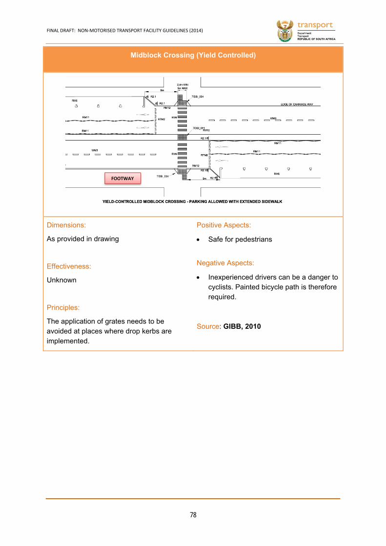
FINAL DRAFT: NON‐MOTORISED TRANSPORT FACILITY GUIDELINES (2014)
78
Midblock Crossing (Yield Controlled)
Dimensions:
As provided in drawing
Effectiveness:
Unknown
Principles:
The application of grates needs to be avoided at places where drop kerbs are implemented.
Positive Aspects:
Safe for pedestrians
Negative Aspects:
Inexperienced drivers can be a danger to cyclists. Painted bicycle path is therefore required.
Source: GIBB, 2010
FOOTWAY
FINAL DRAFT: NON‐MOTORISED TRANSPORT FACILITY GUIDELINES (2014)
79
4.11 Bicycle Crossing Facilities
Bicycle Facilities at Controlled Intersections 4.11.1
Traffic becomes complex when entering an intersection. Due to the complexity
experienced, NMT users are quite vulnerable when approaching intersections.
As indicated, intersections have many conflict points, i.e. places where road users
with different desire lines intersect. Currently the low number of cyclists does not
remind motorised road users to ‘watch out for them’, therefore special infrastructure
measures are required. At high speed and volume roads, total separation is required. An example of an
intersection of two high speed, high volume road intersections is given on the next
page.
A single carriageway is sufficient for motorised transport. A so-called advanced stop
line (or ‘bike box’) can be installed.
As indicated, cyclists are especially vulnerable on South Africa’s roads. Painted
lanes or dyed bitumen are used internationally to emphasise the fact that cyclists
use an intersection (or lane).
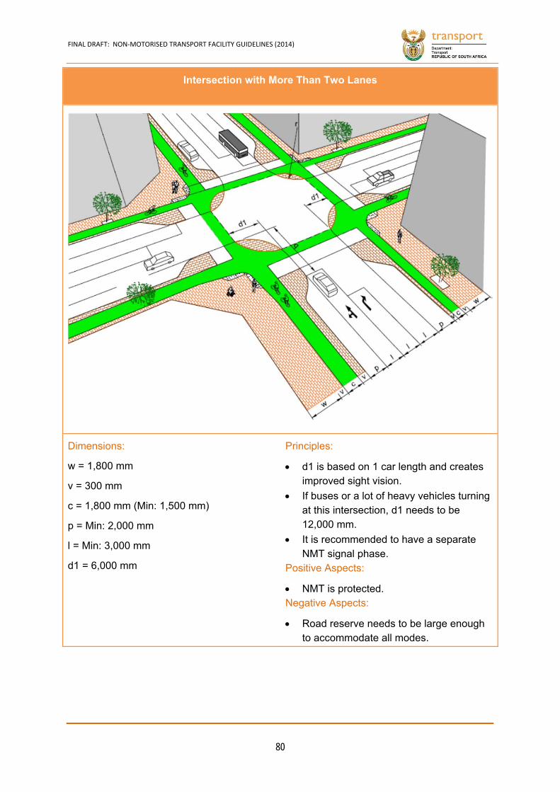
FINAL DRAFT: NON‐MOTORISED TRANSPORT FACILITY GUIDELINES (2014)
80
Intersection with More Than Two Lanes
Dimensions:
w = 1,800 mm
v = 300 mm
c = 1,800 mm (Min: 1,500 mm)
p = Min: 2,000 mm
l = Min: 3,000 mm
d1 = 6,000 mm
Principles:
d1 is based on 1 car length and creates improved sight vision.
If buses or a lot of heavy vehicles turning at this intersection, d1 needs to be 12,000 mm.
It is recommended to have a separate NMT signal phase.
Positive Aspects:
NMT is protected. Negative Aspects:
Road reserve needs to be large enough to accommodate all modes.
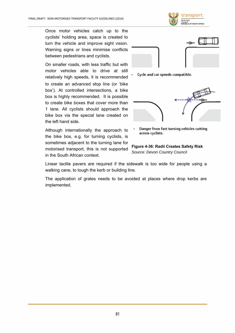
FINAL DRAFT: NON‐MOTORISED TRANSPORT FACILITY GUIDELINES (2014)
81
Once motor vehicles catch up to the
cyclists’ holding area, space is created to
turn the vehicle and improve sight vision.
Warning signs or lines minimise conflicts
between pedestrians and cyclists.
On smaller roads, with less traffic but with
motor vehicles able to drive at still
relatively high speeds, it is recommended
to create an advanced stop line (or ‘bike
box’). At controlled intersections, a bike
box is highly recommended. It is possible
to create bike boxes that cover more than
1 lane. All cyclists should approach the
bike box via the special lane created on
the left hand side.
Although internationally the approach to
the bike box, e.g. for turning cyclists, is
sometimes adjacent to the turning lane for
motorised transport, this is not supported
in the South African context.
Linear tactile pavers are required if the sidewalk is too wide for people using a
walking cane, to tough the kerb or building line.
The application of grates needs to be avoided at places where drop kerbs are
implemented.
Figure 4-36: Radii Creates Safety Risk
Source: Devon Country Council
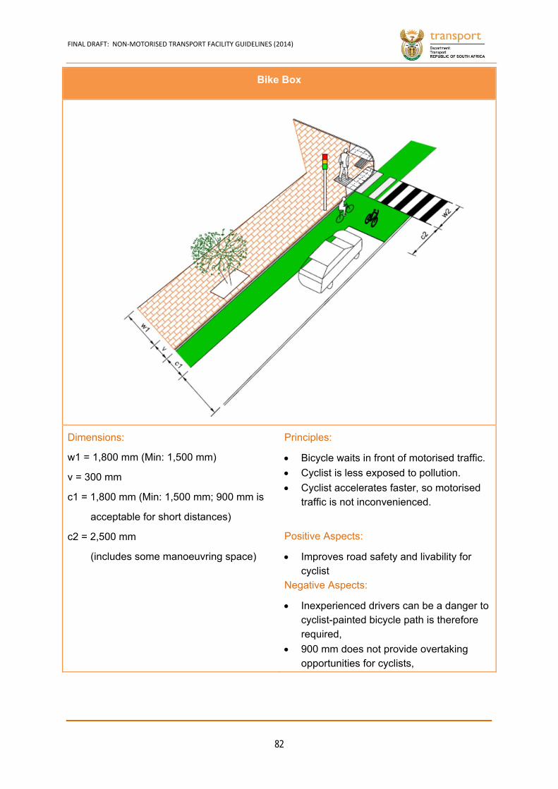
FINAL DRAFT: NON‐MOTORISED TRANSPORT FACILITY GUIDELINES (2014)
82
Bike Box
Dimensions:
w1 = 1,800 mm (Min: 1,500 mm)
v = 300 mm
c1 = 1,800 mm (Min: 1,500 mm; 900 mm is
acceptable for short distances)
c2 = 2,500 mm
(includes some manoeuvring space)
Principles:
Bicycle waits in front of motorised traffic.
Cyclist is less exposed to pollution.
Cyclist accelerates faster, so motorised traffic is not inconvenienced.
Positive Aspects:
Improves road safety and livability for cyclist
Negative Aspects:
Inexperienced drivers can be a danger to cyclist-painted bicycle path is therefore required,
900 mm does not provide overtaking opportunities for cyclists,
FINAL DRAFT: NON‐MOTORISED TRANSPORT FACILITY GUIDELINES (2014)
83
Bicycle Facilities at Uncontrolled intersections 4.11.2
A bike box could be considered at uncontrolled intersections. However, this is not
normally required due to motorised traffic volumes and speeds, as well as NMT
volumes and speeds.
If a bicycle facility is provided on the same level as the carriageway, the intersection
design needs to provide a continuation of the facility. An option is provided on the
next page. Implementing these options needs to be assisted by signage to warn
turning drivers that cyclists have ‘right of way’.
Turning cyclists can bike on the left hand side of the turning lane. No conflicts
should occur, so painted or dyed infrastructure is not required.

FINAL DRAFT: NON‐MOTORISED TRANSPORT FACILITY GUIDELINES (2014)
84
Accommodating Large Numbers of Through Cyclists
Dimensions:
w = 2,000 mm - 3, 000mm
l = 3,000 mm (3,400 mm if accommodating
turning cyclists)
c = 1,800 mm ((Min: 1,500 mm; 900 mm is
acceptable for short distances)
d1 = accommodate comfortable turn
d2 = depending on turning volume
Principles:
Turning motorised traffic gives way to cyclist
Positive Aspects:
Cyclist is not required to detour or make difficult manoeuvres.
Negative Aspects:
Inexperienced drivers can be a danger to cyclists. Painted bicycle path is therefore required.
900 mm does not provide overtaking opportunities for cyclists.

FINAL DRAFT: NON‐MOTORISED TRANSPORT FACILITY GUIDELINES (2014)
85
Bicycle Priority Intersection 4.11.1
In the case of an NMT-only facility,
intersections might still occur. In this case,
however, NMT should receive priority.
The whole intersection is raised. Drop
kerbs are, therefore, not required. The
infrastructure is extremely comfortable for
all NMT users, including people in a
wheelchair, pushing a pram or trolley, etc.
Pedestrians and cyclists have right of way.
Linear tactile pavers are required if the
sidewalk is too wide for people using a
walking cane, so that they do not touch the
kerb or building line.
Drop kerbs are required, depending on pedestrian desire lines. Linear tactile pavers
are required if the sidewalk is too wide for people using a walking cane, to tough the
kerb or building line.
Figure 4-37: Raised Bicycle Priority Intersection(Lelystad)
Picture by Marianne Vanderschuren

FINAL DRAFT: NON‐MOTORISED TRANSPORT FACILITY GUIDELINES (2014)
86
Bicycle Priority Crossing
Dimensions:
w = 1,800 mm (Min: 1,500 mm)
c = 2,500 mm (preferably more)
Principles:
NMT has right of way; motorised transport yields).
Cycling infrastructure should cater for long distances.
Raised pedestrian crossings, and TGSI’s should be used leading to the crossings
Positive Aspects:
Promotes road safety
Cyclists can achieve high speeds Negative Aspects:
Inexperienced drivers can be a danger to cyclist. Painted bicycle lane is, therefore, required.

FINAL DRAFT: NON‐MOTORISED TRANSPORT FACILITY GUIDELINES (2014)
87
4.12 Railway Crossing Facilities
Intersections with railway come with a
safety risk for motorised transport, as
well as NMT. Trains have right of way
at any intersection and given the high
speeds that trains travel at, sight
distances for other road users are
often not sufficient, and physically
impossible to create
Railway crossings can be controlled
and uncontrolled. Given the vast
amount of accidents, controlled
intersections or grade separation are recommended.
Internationally, offset crossings are applied. Again, given the safety risk in the
South African context, such facilities are NOT recommended. A 90-degree crossing
is the only recommended railway intersection.
NMT railway crossings can be combined adjacent to the motorised transport
carriageways on one, but preferably two sides, or exclusively for NMT users. An
example of both options is included. Design principles can be found too.
If non-controlled NMT railway
crossings are implemented, warning
signs need to be added. Figure 4-38
provides a Utah example of painted
STOP signage on the road surface.
Tactile crossing delineation is required
at controlled and uncontrolled railway
crossings. It is also important to have
a clear path in order to efficiently
navigate an at-grade rail crossing.
People with vision impairments should
not have to make decisions as to the
appropriate direction of travel after
entering an at-grade rail crossing.
Figure 4-38: Warning at Rail Crossing
Source: Utah DOT, 2013
Figure 4-39: Example of Delineation Requirements
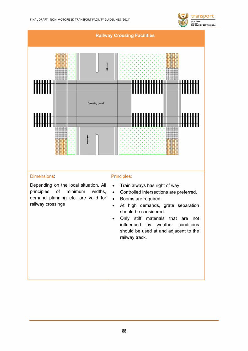
FINAL DRAFT: NON‐MOTORISED TRANSPORT FACILITY GUIDELINES (2014)
88
Railway Crossing Facilities
Dimensions:
Depending on the local situation. All principles of minimum widths, demand planning etc. are valid for railway crossings
Principles:
Train always has right of way.
Controlled intersections are preferred.
Booms are required.
At high demands, grate separation should be considered.
Only stiff materials that are not influenced by weather conditions should be used at and adjacent to the railway track.
CHAPTER 5
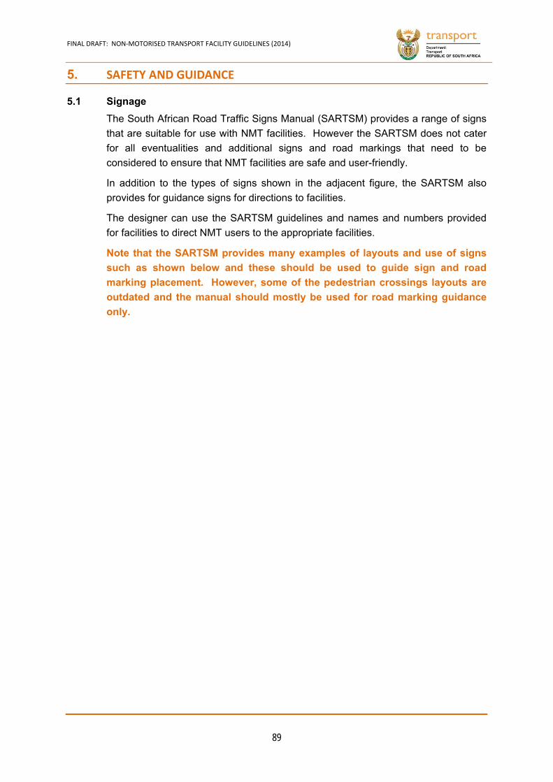
FINAL DRAFT: NON‐MOTORISED TRANSPORT FACILITY GUIDELINES (2014)
89
5. SAFETY AND GUIDANCE
5.1 Signage
The South African Road Traffic Signs Manual (SARTSM) provides a range of signs
that are suitable for use with NMT facilities. However the SARTSM does not cater
for all eventualities and additional signs and road markings that need to be
considered to ensure that NMT facilities are safe and user-friendly.
In addition to the types of signs shown in the adjacent figure, the SARTSM also
provides for guidance signs for directions to facilities.
The designer can use the SARTSM guidelines and names and numbers provided
for facilities to direct NMT users to the appropriate facilities.
Note that the SARTSM provides many examples of layouts and use of signs
such as shown below and these should be used to guide sign and road
marking placement. However, some of the pedestrian crossings layouts are
outdated and the manual should mostly be used for road marking guidance
only.
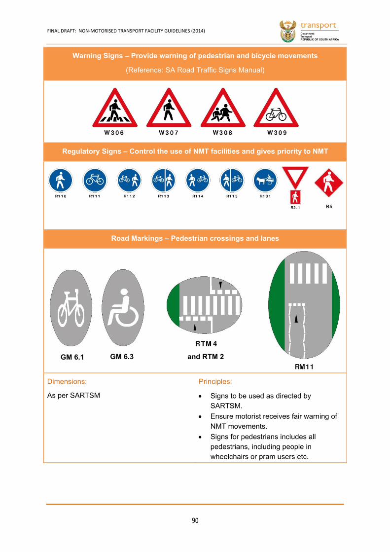
FINAL DRAFT: NON‐MOTORISED TRANSPORT FACILITY GUIDELINES (2014)
90
Warning Signs – Provide warning of pedestrian and bicycle movements
(Reference: SA Road Traffic Signs Manual)
Regulatory Signs – Control the use of NMT facilities and gives priority to NMT
Road Markings – Pedestrian crossings and lanes
Dimensions:
As per SARTSM
Principles:
Signs to be used as directed by SARTSM.
Ensure motorist receives fair warning of NMT movements.
Signs for pedestrians includes all pedestrians, including people in wheelchairs or pram users etc.
GM 6.3 GM 6.1 and RTM 2
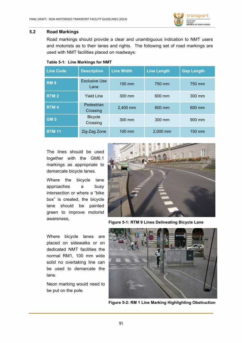
FINAL DRAFT: NON‐MOTORISED TRANSPORT FACILITY GUIDELINES (2014)
91
5.2 Road Markings
Road markings should provide a clear and unambiguous indication to NMT users
and motorists as to their lanes and rights. The following set of road markings are
used with NMT facilities placed on roadways:
Line Code Description Line Width Line Length Gap Length
RM 9 Exclusive Use
Lane 150 mm 750 mm 750 mm
RTM 2 Yield Line 300 mm 600 mm 300 mm
RTM 4 Pedestrian
Crossing 2,400 mm 600 mm 600 mm
GM 5 Bicycle
Crossing 300 mm 300 mm 900 mm
RTM 11 Zig-Zag Zone 100 mm 2,000 mm 150 mm
The lines should be used
together with the GM6.1
markings as appropriate to
demarcate bicycle lanes.
Where the bicycle lane
approaches a busy
intersection or where a “bike
box” is created, the bicycle
lane should be painted
green to improve motorist
awareness,
Where bicycle lanes are
placed on sidewalks or on
dedicated NMT facilities the
normal RM1, 100 mm wide
solid no overtaking line can
be used to demarcate the
lane.
Neon marking would need to
be put on the pole.
Table 5-1: Line Markings for NMT
Figure 5-1: RTM 9 Lines Delineating Bicycle Lane
Figure 5-2: RM 1 Line Marking Highlighting Obstruction
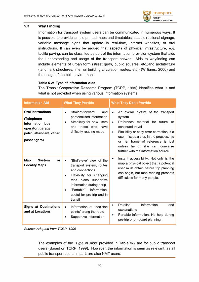
FINAL DRAFT: NON‐MOTORISED TRANSPORT FACILITY GUIDELINES (2014)
92
5.3 Way Finding
Information for transport system users can be communicated in numerous ways. It
is possible to provide simple printed maps and timetables, static directional signage,
variable message signs that update in real-time, internet websites, or oral
instructions. It can even be argued that aspects of physical infrastructure, e.g.
tactile paving, can be classified as part of the information provision system that aids
the understanding and usage of the transport network. Aids to wayfinding can
include elements of urban form (street grids, public squares, etc.)and architecture
(landmark structures, internal building circulation routes, etc.) (Williams, 2006) and
the usage of the built environment.
The Transit Cooperative Research Program (TCRP, 1999) identifies what is and
what is not provided when using various information systems.
Information Aid What They Provide What They Don’t Provide
Oral instructions
(Telephone
information, bus
operator, garage
petrol attendant, other
passengers)
Straight-forward and
personalised information
Simplicity for new users
and those who have
difficulty reading maps
An overall picture of the transport
system
Reference material for future or
continued travel
Flexibility or easy error correction; if a
user misses a step in the process; his
or her frame of reference is lost
unless he or she can converse
further with the information source
Map System or
Locality Maps “Bird’s-eye” view of the
transport system, routes
and connections
Flexibility for changing
trips plans supportive
information during a trip
“Portable” information,
useful for pre-trip and in
transit
Instant accessibility. Not only is the
map a physical object that a potential
user must obtain before trip planning
can begin, but map reading presents
difficulties for many people.
Signs at Destinations
and at Locations Information at “decision
points” along the route
Supportive information
Detailed information and
explanations
Portable information. No help during
pre-trip or on-board planning.
Source: Adapted from TCRP, 1999
The examples of the ‘Type of Aids’ provided in Table 5-2 are for public transport
users (Based on TCRP, 1999). However, the information is seen as relevant, as all
public transport users, in part, are also NMT users.
Table 5-2: Type of Information Aids
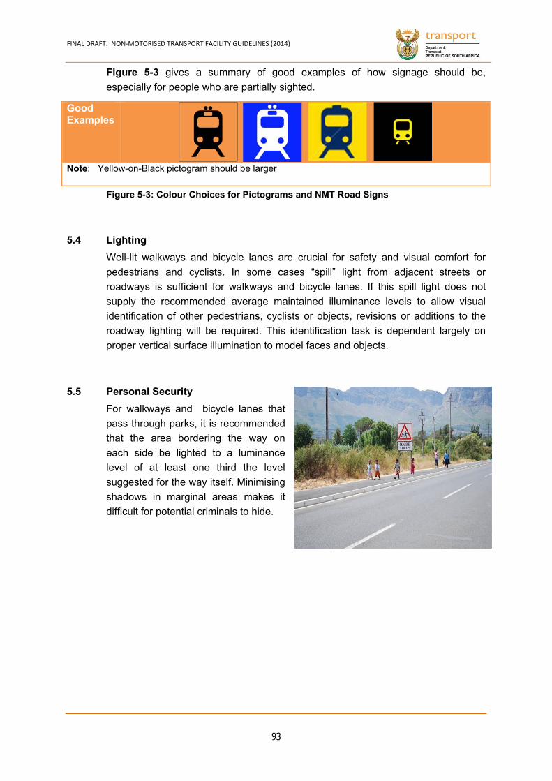
FINAL DRAFT: NON‐MOTORISED TRANSPORT FACILITY GUIDELINES (2014)
93
Figure 5-3 gives a summary of good examples of how signage should be,
especially for people who are partially sighted.
Good Examples
Note: Yellow-on-Black pictogram should be larger
5.4 Lighting
Well-lit walkways and bicycle lanes are crucial for safety and visual comfort for
pedestrians and cyclists. In some cases “spill” light from adjacent streets or
roadways is sufficient for walkways and bicycle lanes. If this spill light does not
supply the recommended average maintained illuminance levels to allow visual
identification of other pedestrians, cyclists or objects, revisions or additions to the
roadway lighting will be required. This identification task is dependent largely on
proper vertical surface illumination to model faces and objects.
5.5 Personal Security
For walkways and bicycle lanes that
pass through parks, it is recommended
that the area bordering the way on
each side be lighted to a luminance
level of at least one third the level
suggested for the way itself. Minimising
shadows in marginal areas makes it
difficult for potential criminals to hide.
Figure 5-3: Colour Choices for Pictograms and NMT Road Signs

FINAL DRAFT: NON‐MOTORISED TRANSPORT FACILITY GUIDELINES (2014)
94
5.6 Traffic Calming
Table 5-3 provides an overview of the applicability of traffic calming facilities on
highways, mobility spines and access roads.
Type Application Impacts
Highway Mobility Spine
Access Road
Impact on Traffic
Volumes
Impact on Vehicle Speed
Reduction
Grade separation √ √ - Possible Yes
Speed hump/table - - √ Possible Yes
Raised crosswalk - With caution √ Possible Yes
Raised intersection - With caution √ Possible Yes
Textured pavements - √ √ Possible Yes
Rumble strips √ √ √ No Yes
Traffic (mini) circle - - √ Possible Yes
Roundabout - √ - Not likely Yes
Chicanes - - √ Yes Yes
Realigned intersection
- √ √ Possible Yes
Tight radii - √ √ Possible Yes
Neckdowns - √ √ Possible Yes
Centre island narrowing
- √ √ Possible Yes
Chokers - √ √ Possible Yes
‘Road diets’ - √ √ Yes Yes
Bicycle lanes - √ √ Possible Possible
Speed limits √ √ √ Yes Yes
Perceptual design With caution √ √ Possible Yes
Full closure - - √ Yes Yes
Half closure - √ √ Yes Possible
Diagonal diverters - √ √ Yes Possible
Lateral shift - √ √ No Yes
Median barriers √ √ - Yes Yes
Table 5-3: Traffic Calming Types, Application and Impacts
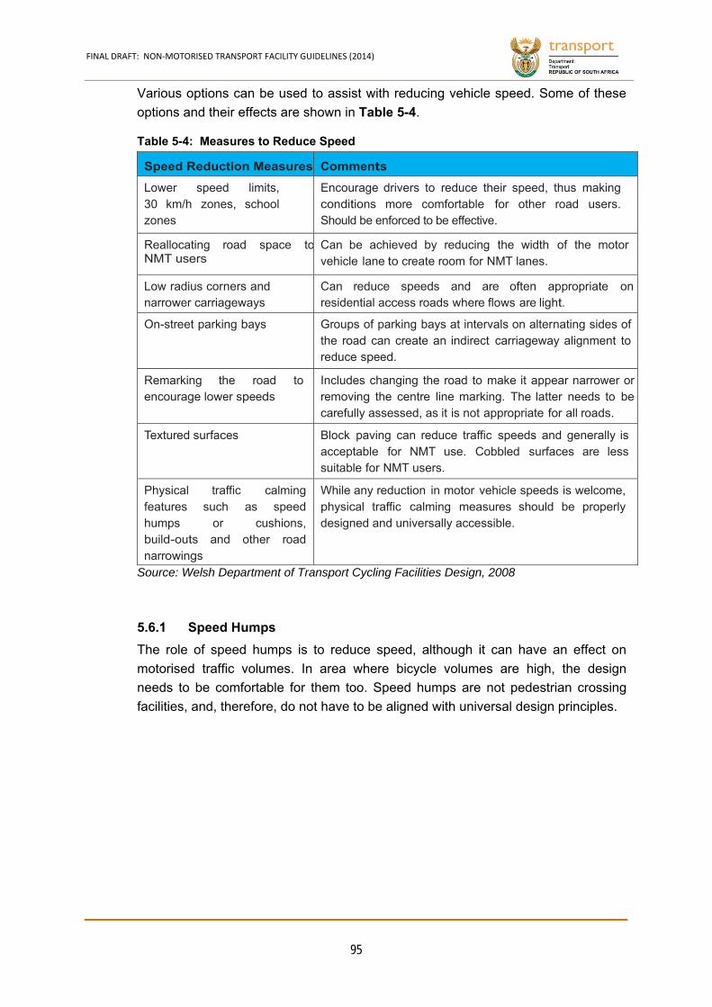
FINAL DRAFT: NON‐MOTORISED TRANSPORT FACILITY GUIDELINES (2014)
95
Various options can be used to assist with reducing vehicle speed. Some of these
options and their effects are shown in Table 5-4.
Speed Reduction Measures Comments
Lower speed limits, 30 km/h zones, school zones
Encourage drivers to reduce their speed, thus making conditions more comfortable for other road users. Should be enforced to be effective.
Reallocating road space toNMT users
Can be achieved by reducing the width of the motor vehicle lane to create room for NMT lanes.
Low radius corners and narrower carriageways
Can reduce speeds and are often appropriate on residential access roads where flows are light.
On-street parking bays Groups of parking bays at intervals on alternating sides of the road can create an indirect carriageway alignment to reduce speed.
Remarking the road to encourage lower speeds
Includes changing the road to make it appear narrower orremoving the centre line marking. The latter needs to becarefully assessed, as it is not appropriate for all roads.
Textured surfaces Block paving can reduce traffic speeds and generally is acceptable for NMT use. Cobbled surfaces are less suitable for NMT users.
Physical traffic calming features such as speed humps or cushions, build-outs and other road narrowings
While any reduction in motor vehicle speeds is welcome, physical traffic calming measures should be properly designed and universally accessible.
Source: Welsh Department of Transport Cycling Facilities Design, 2008
Speed Humps 5.6.1
The role of speed humps is to reduce speed, although it can have an effect on
motorised traffic volumes. In area where bicycle volumes are high, the design
needs to be comfortable for them too. Speed humps are not pedestrian crossing
facilities, and, therefore, do not have to be aligned with universal design principles.
Table 5-4: Measures to Reduce Speed
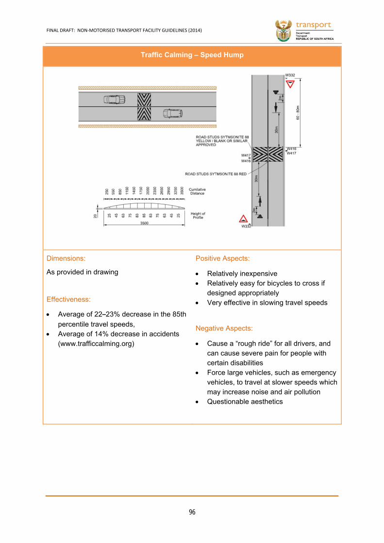
FINAL DRAFT: NON‐MOTORISED TRANSPORT FACILITY GUIDELINES (2014)
96
Traffic Calming – Speed Hump
Dimensions:
As provided in drawing
Effectiveness:
Average of 22–23% decrease in the 85th
percentile travel speeds, Average of 14% decrease in accidents
(www.trafficcalming.org)
Positive Aspects:
Relatively inexpensive Relatively easy for bicycles to cross if
designed appropriately Very effective in slowing travel speeds
Negative Aspects:
Cause a “rough ride” for all drivers, and can cause severe pain for people with certain disabilities
Force large vehicles, such as emergency vehicles, to travel at slower speeds which may increase noise and air pollution
Questionable aesthetics
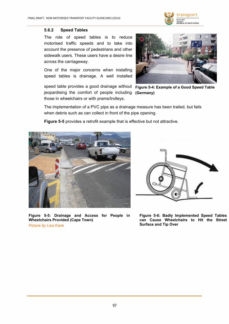
FINAL DRAFT: NON‐MOTORISED TRANSPORT FACILITY GUIDELINES (2014)
97
Speed Tables 5.6.2
The role of speed tables is to reduce
motorised traffic speeds and to take into
account the presence of pedestrians and other
sidewalk users. These users have a desire line
across the carriageway.
One of the major concerns when installing
speed tables is drainage. A well installed
speed table provides a good drainage without
jeopardising the comfort of people including
those in wheelchairs or with prams/trolleys.
The implementation of a PVC pipe as a drainage measure has been trailed, but fails
when debris such as can collect in front of the pipe opening.
Figure 5-5 provides a retrofit example that is effective but not attractive.
Figure 5-4: Example of a Good Speed Table
(Germany)
Figure 5-6: Badly Implemented Speed Tablescan Cause Wheelchairs to Hit the StreetSurface and Tip Over
Figure 5-5: Drainage and Access for People inWheelchairs Provided (Cape Town)
Picture by Lisa Kane
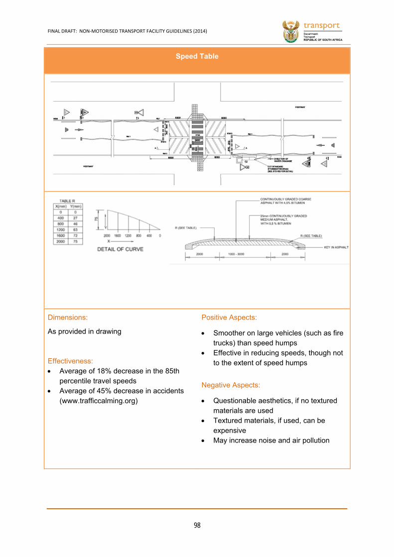
FINAL DRAFT: NON‐MOTORISED TRANSPORT FACILITY GUIDELINES (2014)
98
Speed Table
Dimensions:
As provided in drawing
Effectiveness: Average of 18% decrease in the 85th
percentile travel speeds Average of 45% decrease in accidents
(www.trafficcalming.org)
Positive Aspects:
Smoother on large vehicles (such as fire trucks) than speed humps
Effective in reducing speeds, though not to the extent of speed humps
Negative Aspects:
Questionable aesthetics, if no textured materials are used
Textured materials, if used, can be expensive
May increase noise and air pollution
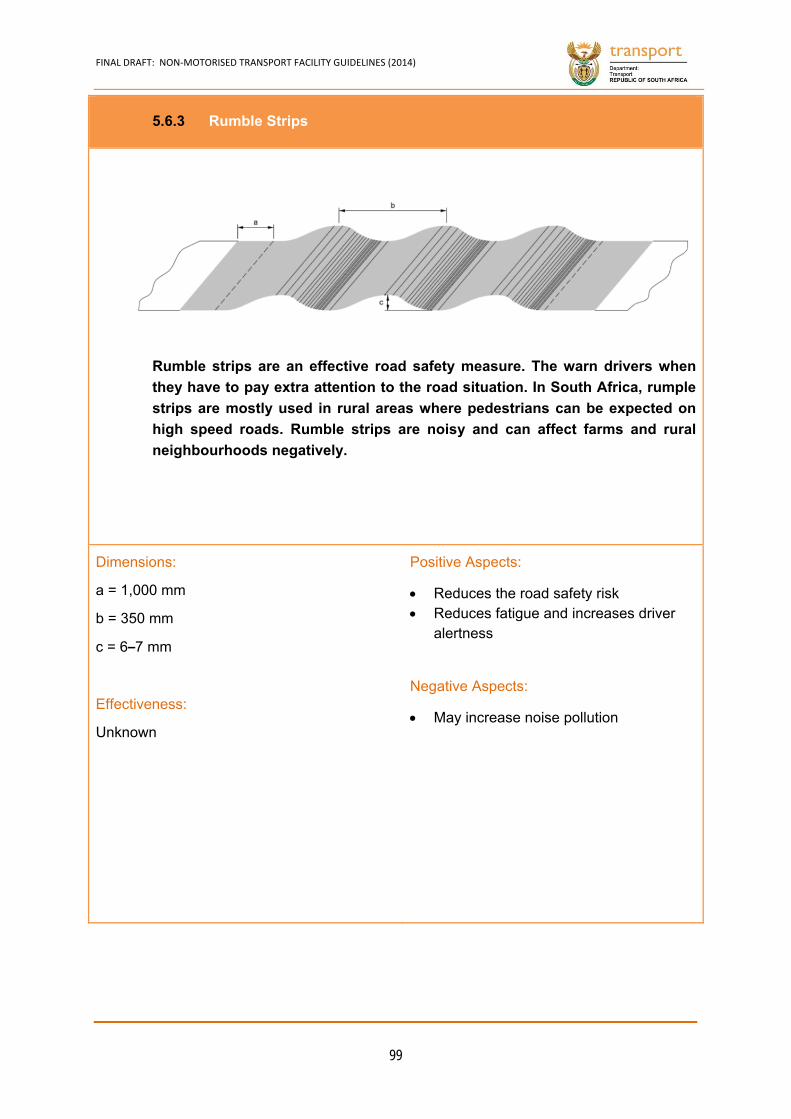
FINAL DRAFT: NON‐MOTORISED TRANSPORT FACILITY GUIDELINES (2014)
99
Rumble Strips 5.6.3
Rumble strips are an effective road safety measure. The warn drivers when
they have to pay extra attention to the road situation. In South Africa, rumple
strips are mostly used in rural areas where pedestrians can be expected on
high speed roads. Rumble strips are noisy and can affect farms and rural
neighbourhoods negatively.
Dimensions:
a = 1,000 mm
b = 350 mm
c = 6–7 mm
Effectiveness:
Unknown
Positive Aspects:
Reduces the road safety risk Reduces fatigue and increases driver
alertness
Negative Aspects:
May increase noise pollution
FINAL DRAFT: NON‐MOTORISED TRANSPORT FACILITY GUIDELINES (2014)
100
Roundabouts and Traffic Circles 5.6.4
Roundabouts and traffic circles are effective traffic calming measures. Badly
installed speed humps and tables damage vehicles lead to additional noise and air
pollution. Roundabouts and circles do not have this negative impact.
Roundabouts have less conflict points than intersections. Road safety, therefore,
improves when intersections are replaced (assuming correct driver, walking and
cycling behaviour).
If cyclists are combined with motorised traffic on roundabouts, only multi-lane or
high speed/volume circles require a separate bicycle lane.
If speeds and/or volumes are high, it is recommended to create a setback which is
at least 1 car length (6 m), or more is there is a high percentage of heavy vehicles.
The application of grates needs to be avoided at places where drop kerbs are
implemented.
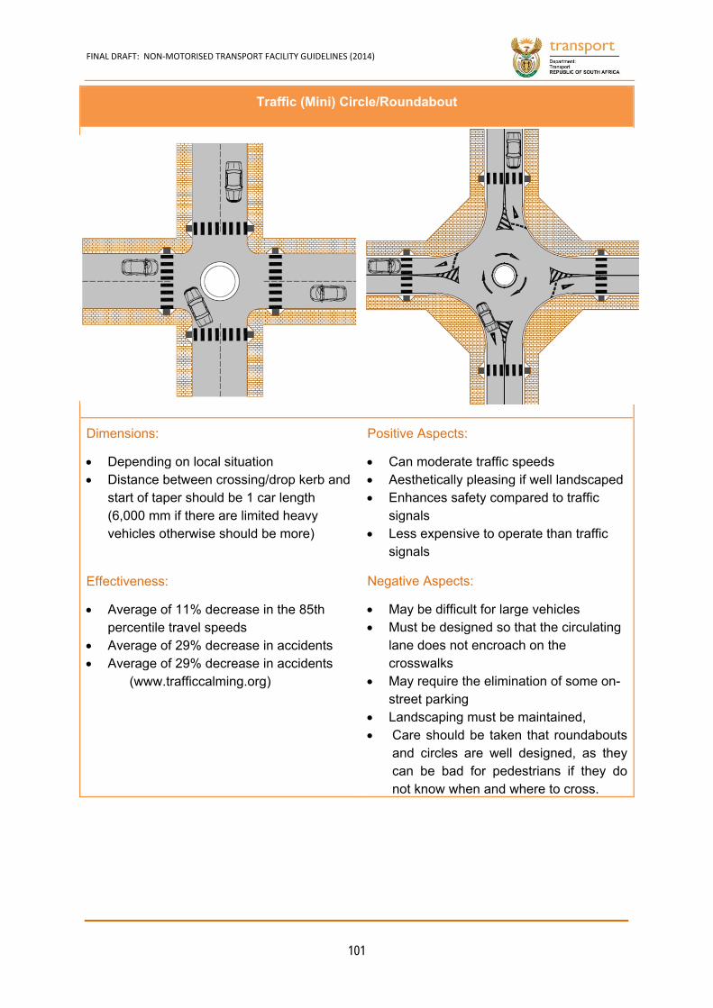
FINAL DRAFT: NON‐MOTORISED TRANSPORT FACILITY GUIDELINES (2014)
101
Traffic (Mini) Circle/Roundabout
Dimensions:
Depending on local situation Distance between crossing/drop kerb and
start of taper should be 1 car length (6,000 mm if there are limited heavy vehicles otherwise should be more)
Effectiveness:
Average of 11% decrease in the 85th percentile travel speeds
Average of 29% decrease in accidents Average of 29% decrease in accidents
(www.trafficcalming.org)
Positive Aspects:
Can moderate traffic speeds Aesthetically pleasing if well landscaped Enhances safety compared to traffic
signals Less expensive to operate than traffic
signals
Negative Aspects:
May be difficult for large vehicles Must be designed so that the circulating
lane does not encroach on the crosswalks
May require the elimination of some on-street parking
Landscaping must be maintained, Care should be taken that roundabouts
and circles are well designed, as they can be bad for pedestrians if they do not know when and where to cross.
FINAL DRAFT: NON‐MOTORISED TRANSPORT FACILITY GUIDELINES (2014)
102
Chicanes 5.6.5
Chicanes reduce the width of a street in order to make drivers slow down. Chicanes
involve building out the kerb, usually on alternate sides of the road, to effectively
introduce bends into an otherwise straight road.
Chicanes have been very effective in slowing down traffic on high volume roads
approaching rural towns.
If NMT desire lines exist near chicanes, other types of facilities need to be added.
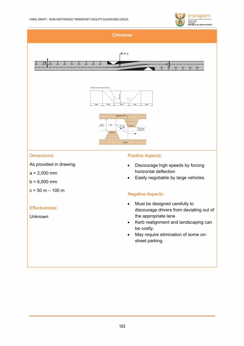
FINAL DRAFT: NON‐MOTORISED TRANSPORT FACILITY GUIDELINES (2014)
103
Chicanes
Dimensions:
As provided in drawing
a = 2,000 mm
b = 6,000 mm
c = 50 m – 100 m
Effectiveness:
Unknown
Positive Aspects:
Discourage high speeds by forcing horizontal deflection
Easily negotiable by large vehicles.
Negative Aspects:
Must be designed carefully to discourage drivers from deviating out of the appropriate lane
Kerb realignment and landscaping can be costly.
May require elimination of some on-street parking
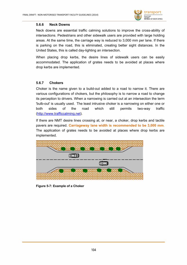
FINAL DRAFT: NON‐MOTORISED TRANSPORT FACILITY GUIDELINES (2014)
104
Neck Downs 5.6.6
Neck downs are essential traffic calming solutions to improve the cross-ability of
intersections. Pedestrians and other sidewalk users are provided with large holding
areas. At the same time, the carriage way is reduced to 3,000 mm per lane. If there
is parking on the road, this is eliminated, creating better sight distances. In the
United States, this is called day-lighting an intersection.
When placing drop kerbs, the desire lines of sidewalk users can be easily
accommodated. The application of grates needs to be avoided at places where
drop kerbs are implemented.
Chokers 5.6.7
Choker is the name given to a build-out added to a road to narrow it. There are
various configurations of chokers, but the philosophy is to narrow a road to change
its perception to drivers. When a narrowing is carried out at an intersection the term
'bulb-out' is usually used. The least intrusive choker is a narrowing on either one or
both sides of the road which still permits two-way traffic
(http://www.trafficcalming.net).
If there are NMT desire lines crossing at, or near, a choker, drop kerbs and tactile
pavers are required. Carriageway lane width is recommended to be 3,000 mm.
The application of grates needs to be avoided at places where drop kerbs are
implemented.
Figure 5-7: Example of a Choker
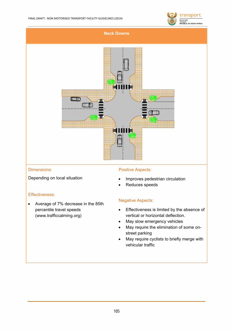
FINAL DRAFT: NON‐MOTORISED TRANSPORT FACILITY GUIDELINES (2014)
105
Neck Downs
Dimensions:
Depending on local situation
Effectiveness:
Average of 7% decrease in the 85th percentile travel speeds (www.trafficcalming.org)
Positive Aspects:
Improves pedestrian circulation Reduces speeds
Negative Aspects:
Effectiveness is limited by the absence of vertical or horizontal deflection.
May slow emergency vehicles May require the elimination of some on-
street parking May require cyclists to briefly merge with
vehicular traffic
FINAL DRAFT: NON‐MOTORISED TRANSPORT FACILITY GUIDELINES (2014)
106
Half Closure 5.6.8
Closures and half closures are typical volume measures. In South Africa a lot of
closures can be found at so called estates. From a motorised traffic point of view,
road closures are very effective measures, elimination though traffic. However, for
the vast amount of pedestrians in the country, a road closure, including fencing, as
witnessed around estates, creates long detours and frustration.
A half closure does not have negative impacts for NMT. Cyclists should be allowed
to use one-way roads, created by half closures, in both directions. Half closures can
be considered around urban primary schools
Sidewalk users should be accommodated, according to their desire lines. The
application of grates needs to be avoided at places where drop kerbs are
implemented. However, the expectation is that it will be safe for children to play on
the street inside and that may not be so as cars go dangerously fast
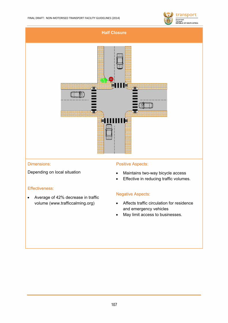
FINAL DRAFT: NON‐MOTORISED TRANSPORT FACILITY GUIDELINES (2014)
107
Half Closure
Dimensions:
Depending on local situation
Effectiveness:
Average of 42% decrease in traffic volume (www.trafficcalming.org)
Positive Aspects:
Maintains two-way bicycle access Effective in reducing traffic volumes.
Negative Aspects:
Affects traffic circulation for residence and emergency vehicles
May limit access to businesses.
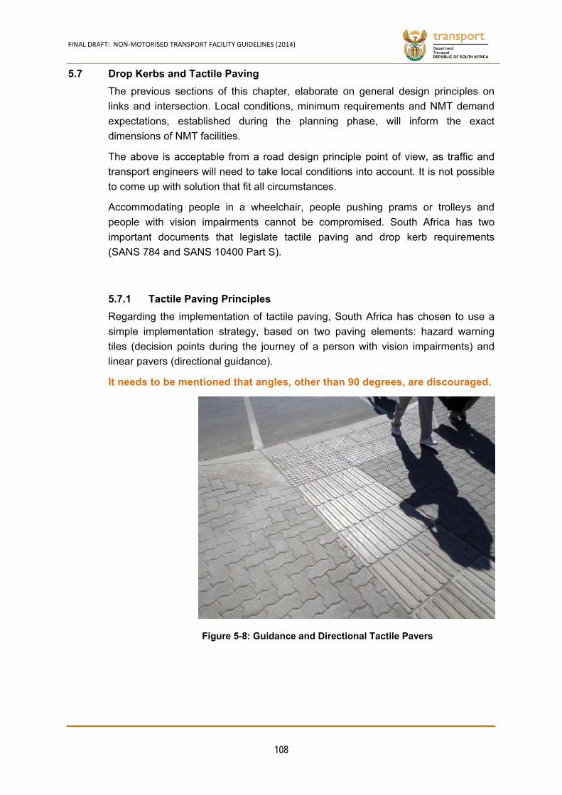
FINAL DRAFT: NON‐MOTORISED TRANSPORT FACILITY GUIDELINES (2014)
108
5.7 Drop Kerbs and Tactile Paving
The previous sections of this chapter, elaborate on general design principles on
links and intersection. Local conditions, minimum requirements and NMT demand
expectations, established during the planning phase, will inform the exact
dimensions of NMT facilities.
The above is acceptable from a road design principle point of view, as traffic and
transport engineers will need to take local conditions into account. It is not possible
to come up with solution that fit all circumstances.
Accommodating people in a wheelchair, people pushing prams or trolleys and
people with vision impairments cannot be compromised. South Africa has two
important documents that legislate tactile paving and drop kerb requirements
(SANS 784 and SANS 10400 Part S).
Tactile Paving Principles 5.7.1
Regarding the implementation of tactile paving, South Africa has chosen to use a
simple implementation strategy, based on two paving elements: hazard warning
tiles (decision points during the journey of a person with vision impairments) and
linear pavers (directional guidance).
It needs to be mentioned that angles, other than 90 degrees, are discouraged.
Figure 5-8: Guidance and Directional Tactile Pavers
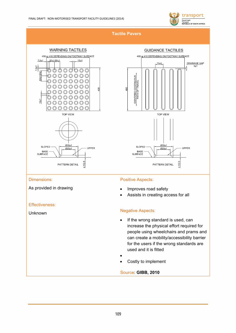
FINAL DRAFT: NON‐MOTORISED TRANSPORT FACILITY GUIDELINES (2014)
109
Tactile Pavers
Dimensions:
As provided in drawing
Effectiveness:
Unknown
Positive Aspects:
Improves road safety Assists in creating access for all
Negative Aspects:
If the wrong standard is used, can increase the physical effort required for people using wheelchairs and prams and can create a mobility/accessibility barrier for the users if the wrong standards are used and it is fitted
Costly to implement Source: GIBB, 2010
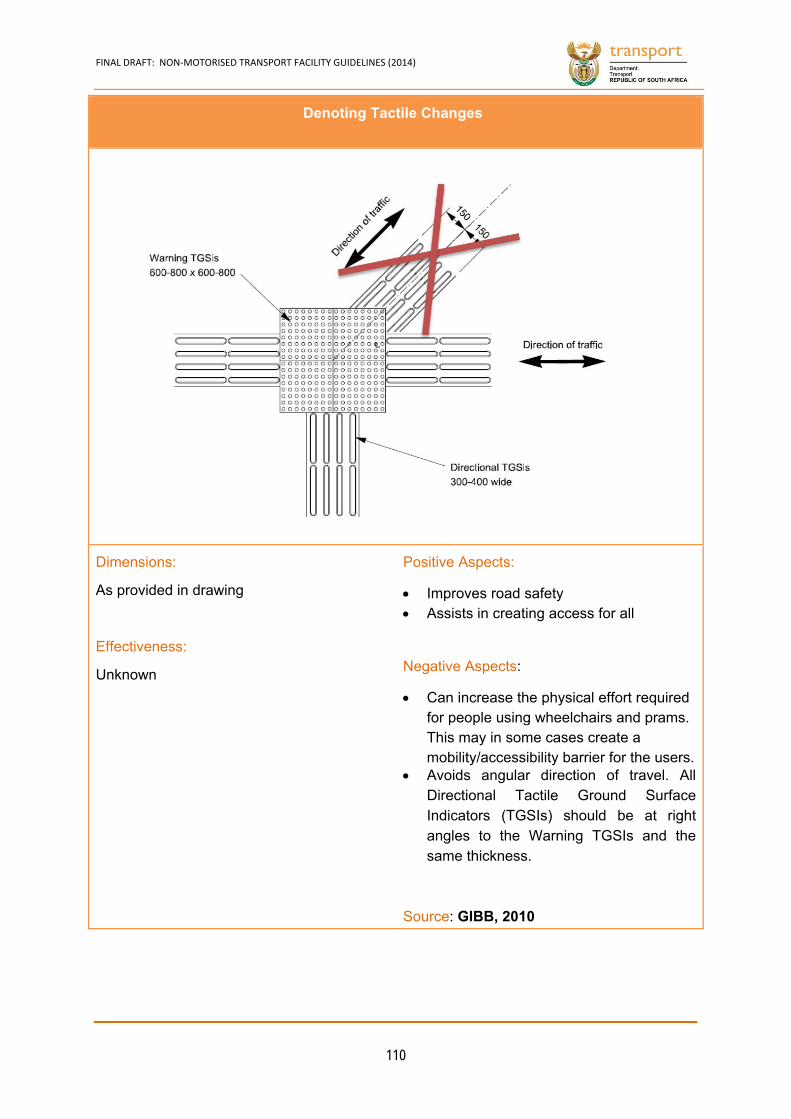
FINAL DRAFT: NON‐MOTORISED TRANSPORT FACILITY GUIDELINES (2014)
110
Denoting Tactile Changes
Dimensions:
As provided in drawing
Effectiveness:
Unknown
Positive Aspects:
Improves road safety Assists in creating access for all
Negative Aspects:
Can increase the physical effort required for people using wheelchairs and prams. This may in some cases create a mobility/accessibility barrier for the users.
Avoids angular direction of travel. All Directional Tactile Ground Surface Indicators (TGSIs) should be at right angles to the Warning TGSIs and the same thickness.
Source: GIBB, 2010
FINAL DRAFT: NON‐MOTORISED TRANSPORT FACILITY GUIDELINES (2014)
111
Drop Kerbs or Kerb Cuts at Locations without Traffic Signals 5.7.2
When the need for tactile paving has been established, the incorporated into drop
kerb design is required. The implementation of tactile paving and drop kerbs is
often inappropriate in South Africa. It is, therefore, necessary to follow the guidance
provided in this document closely, as the correct implementation of appropriate
infrastructure is non-negotiable.
A drop kerb is at least 1,200 mm wide. The full width required hazard warning tiles.
Hazard warning tiles should be at least 600 mm deep (2 rows, preferably 3 rows of
pavers).
The slope of drop kerbs is ideally 1:20 and cannot be less than 1:12. The latter
should only be applied in exceptional circumstances, when space does not allow for
a less steep slope.
The runoff of rain water needs to be accommodated on all sidewalks, including on
the landing off a drop kerb. A slope of 1:50 is required.
NMT users, including people using wheelchairs need to be accommodated behind
the drop kerb on the landing. A passing space is required. If there is a lot of space,
a less steep slope can be provided. Design details for drop kerbs at uncontrolled
intersections are provided in the figures on the next page.
In case a slope of 1:12 is not possible without sacrificing the landing, the whole
sidewalk needs to be dropped. An example of a dropped sidewalk is provided in
Error! Reference source not found..
In all cases, a safety buffer (300 mm) is required at the road edge, to avoid unsafe
situations while people who are blind or partially sighted are waiting to cross.
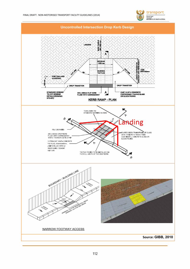
FINAL DRAFT: NON‐MOTORISED TRANSPORT FACILITY GUIDELINES (2014)
112
Uncontrolled Intersection Drop Kerb Design
Source: GIBB, 2010
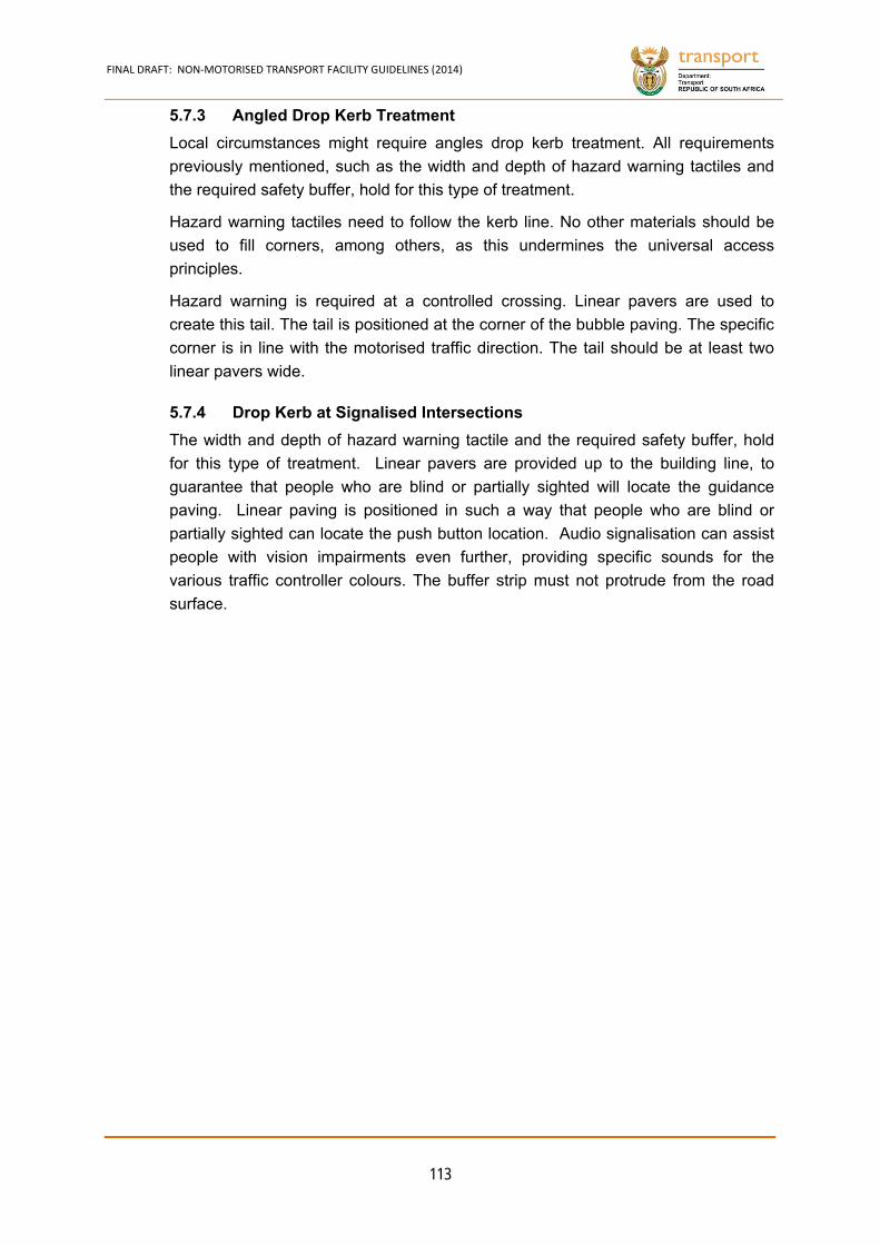
FINAL DRAFT: NON‐MOTORISED TRANSPORT FACILITY GUIDELINES (2014)
113
Angled Drop Kerb Treatment 5.7.3
Local circumstances might require angles drop kerb treatment. All requirements
previously mentioned, such as the width and depth of hazard warning tactiles and
the required safety buffer, hold for this type of treatment.
Hazard warning tactiles need to follow the kerb line. No other materials should be
used to fill corners, among others, as this undermines the universal access
principles.
Hazard warning is required at a controlled crossing. Linear pavers are used to
create this tail. The tail is positioned at the corner of the bubble paving. The specific
corner is in line with the motorised traffic direction. The tail should be at least two
linear pavers wide.
Drop Kerb at Signalised Intersections 5.7.4
The width and depth of hazard warning tactile and the required safety buffer, hold
for this type of treatment. Linear pavers are provided up to the building line, to
guarantee that people who are blind or partially sighted will locate the guidance
paving. Linear paving is positioned in such a way that people who are blind or
partially sighted can locate the push button location. Audio signalisation can assist
people with vision impairments even further, providing specific sounds for the
various traffic controller colours. The buffer strip must not protrude from the road
surface.
FINAL DRAFT: NON‐MOTORISED TRANSPORT FACILITY GUIDELINES (2014)
114
Angular Treatment Kerb Ramp
Drop Kerb at Signalised Intersection
Source: GIBB, 2010
FINAL DRAFT: NON‐MOTORISED TRANSPORT FACILITY GUIDELINES (2014)
115
5.8 Construction / Development Sites
Road works at road construction sites can pose unexpected problems for
pedestrians and cyclists. For persons with disabilities, such work can severely limit
or even totally preclude travel through the area. Provisions should be made for safe
and clearly delineated paths through a construction zone.
Principles of Design 5.8.1
There are a number of basic considerations in planning for pedestrians and cyclists
at construction sites:
Persons should not be led into conflicts with work site vehicles, equipment,
and operations, as well as into conflicts with vehicles moving through or around
the construction site.
Persons should be provided with a safe, convenient path that replicates as
nearly as practicable the most desirable characteristics of the existing travel
ways.
Pedestrian and bicycle traffic should where possible be separated from both
construction site activity and vehicular traffic.
A series of road signs have been developed to cater for pedestrians at road
construction sites and should be used whenever the appropriate situation
arises. According to the Road Traffic Signs Manual, it is an important aspect
of the safety arrangements of roadworks sites that specific accommodation
should be made for pedestrians.
The manual states that any authority or contractor not making provision for
pedestrians could, in the event of an accident, find themselves facing serious
litigation.
The temporary signing of roadworks in urban areas is commonly influenced
by having limited space to accommodate road signs and traffic; high traffic and
pedestrian volumes and the need to maintain access to many properties.
For temporary road signs to be effective in urban areas, there must be
availability of street lighting; there should be no obstruction of signs by trees,
street furniture and large vehicles and the sight distances must be adequate.
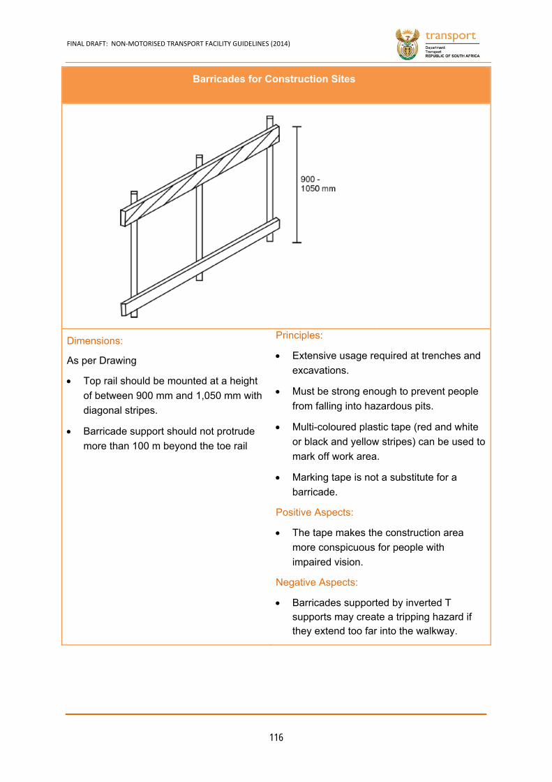
FINAL DRAFT: NON‐MOTORISED TRANSPORT FACILITY GUIDELINES (2014)
116
Barricades for Construction Sites
Dimensions:
As per Drawing
Top rail should be mounted at a height
of between 900 mm and 1,050 mm with
diagonal stripes.
Barricade support should not protrude
more than 100 m beyond the toe rail
Principles:
Extensive usage required at trenches and
excavations.
Must be strong enough to prevent people
from falling into hazardous pits.
Multi-coloured plastic tape (red and white
or black and yellow stripes) can be used to
mark off work area.
Marking tape is not a substitute for a
barricade.
Positive Aspects:
The tape makes the construction area
more conspicuous for people with
impaired vision.
Negative Aspects:
Barricades supported by inverted T supports may create a tripping hazard if they extend too far into the walkway.

FINAL DRAFT: NON‐MOTORISED TRANSPORT FACILITY GUIDELINES (2014)
117
Sidewalk Diversions
Dimensions:
As per Drawing
Top rail to be mounted at a height of
between 900 mm and 1,050 mm with
diagonal stripes
Barricade support should not protrude
more than 100 m beyond the toe rail
Principles:
Provides for isolated excavation with no
other roadworks, e.g. local repair to a
water main, sewer, electrical cable, etc.
Signs within a larger site need to be
modified where more than one
excavation occurs based on site
requirements
More details regarding road signs and
markings required at construction work
zones are given in the Road Traffic
Signs Manual
Remarks:
The signs given in the figure are typical only and are not intended to be a definitive inventory.
Source:
Road Traffic Signs Manual
CHAPTER 6
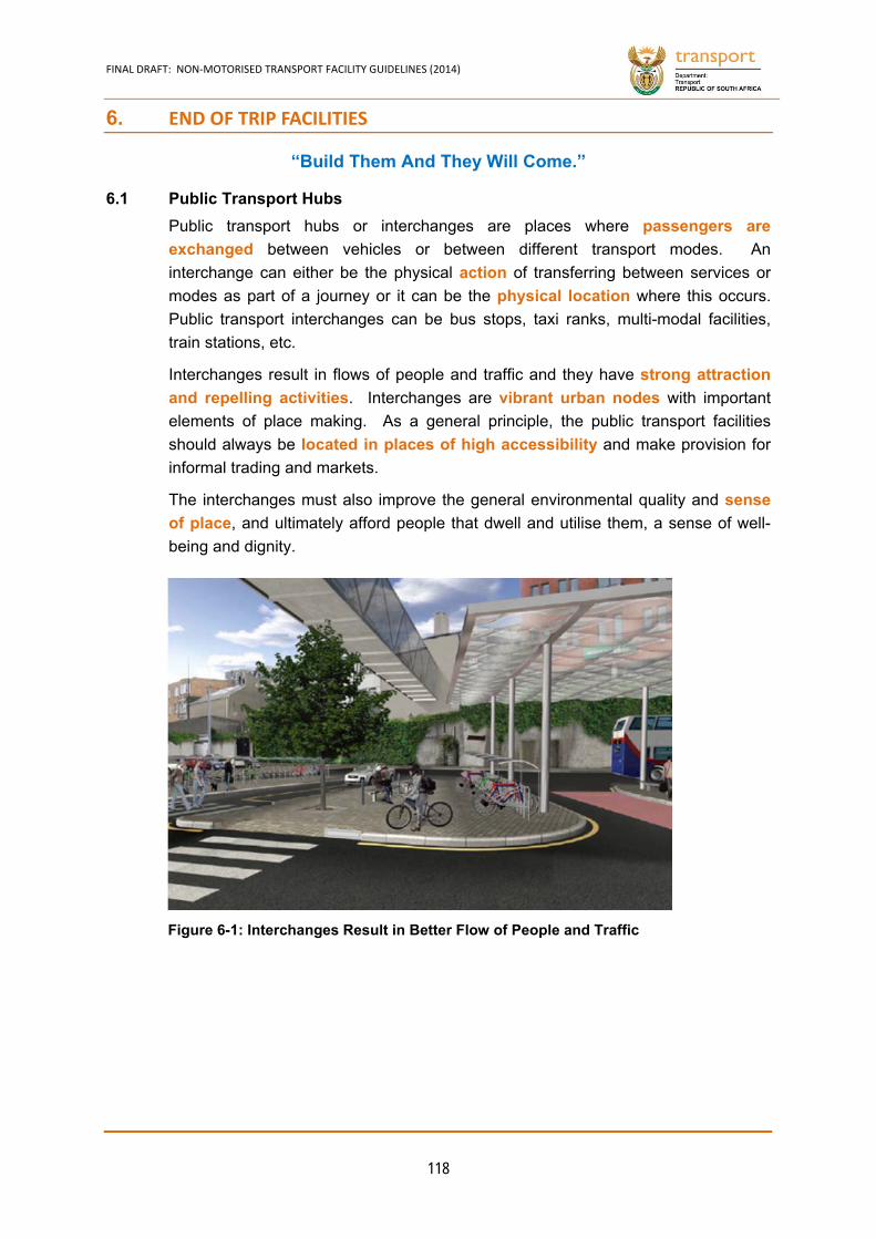
FINAL DRAFT: NON‐MOTORISED TRANSPORT FACILITY GUIDELINES (2014)
118
Figure 6-1: Interchanges Result in Better Flow of People and Traffic
6. END OF TRIP FACILITIES
“Build Them And They Will Come.”
6.1 Public Transport Hubs
Public transport hubs or interchanges are places where passengers are
exchanged between vehicles or between different transport modes. An
interchange can either be the physical action of transferring between services or
modes as part of a journey or it can be the physical location where this occurs.
Public transport interchanges can be bus stops, taxi ranks, multi-modal facilities,
train stations, etc.
Interchanges result in flows of people and traffic and they have strong attraction
and repelling activities. Interchanges are vibrant urban nodes with important
elements of place making. As a general principle, the public transport facilities
should always be located in places of high accessibility and make provision for
informal trading and markets.
The interchanges must also improve the general environmental quality and sense
of place, and ultimately afford people that dwell and utilise them, a sense of well-
being and dignity.
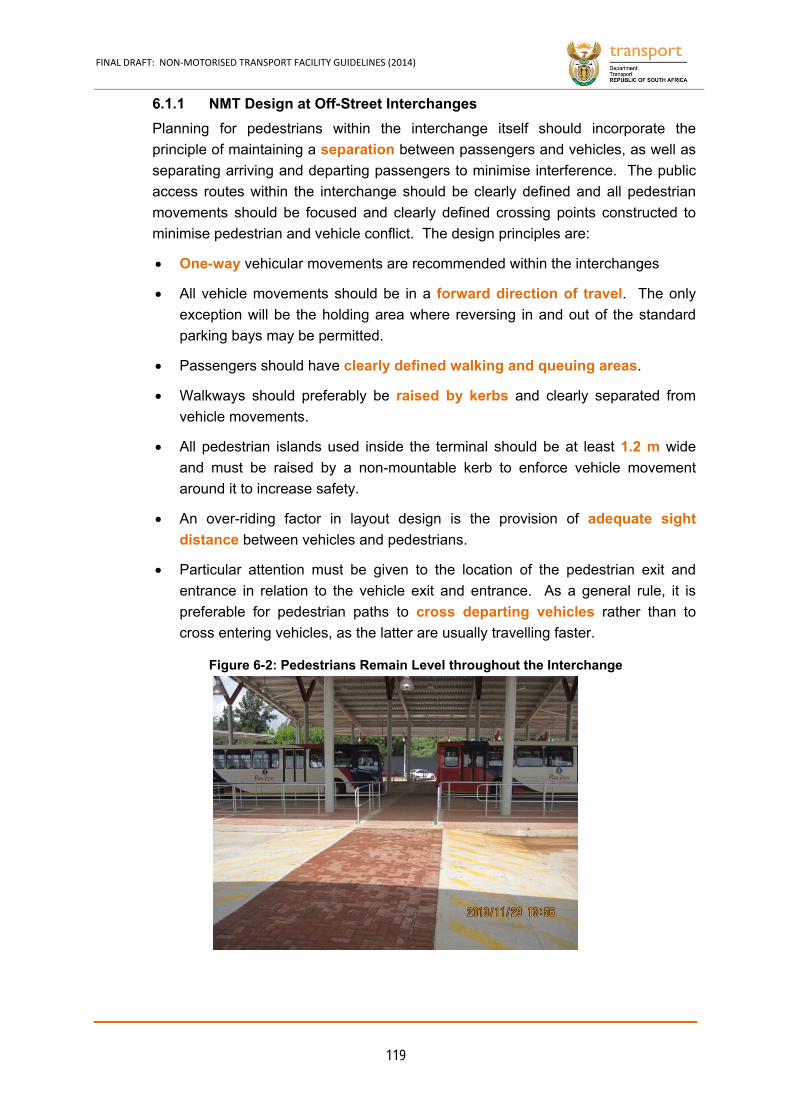
FINAL DRAFT: NON‐MOTORISED TRANSPORT FACILITY GUIDELINES (2014)
119
NMT Design at Off-Street Interchanges 6.1.1
Planning for pedestrians within the interchange itself should incorporate the
principle of maintaining a separation between passengers and vehicles, as well as
separating arriving and departing passengers to minimise interference. The public
access routes within the interchange should be clearly defined and all pedestrian
movements should be focused and clearly defined crossing points constructed to
minimise pedestrian and vehicle conflict. The design principles are:
One-way vehicular movements are recommended within the interchanges
All vehicle movements should be in a forward direction of travel. The only
exception will be the holding area where reversing in and out of the standard
parking bays may be permitted.
Passengers should have clearly defined walking and queuing areas.
Walkways should preferably be raised by kerbs and clearly separated from
vehicle movements.
All pedestrian islands used inside the terminal should be at least 1.2 m wide
and must be raised by a non-mountable kerb to enforce vehicle movement
around it to increase safety.
An over-riding factor in layout design is the provision of adequate sight
distance between vehicles and pedestrians.
Particular attention must be given to the location of the pedestrian exit and
entrance in relation to the vehicle exit and entrance. As a general rule, it is
preferable for pedestrian paths to cross departing vehicles rather than to
cross entering vehicles, as the latter are usually travelling faster.
Figure 6-2: Pedestrians Remain Level throughout the Interchange
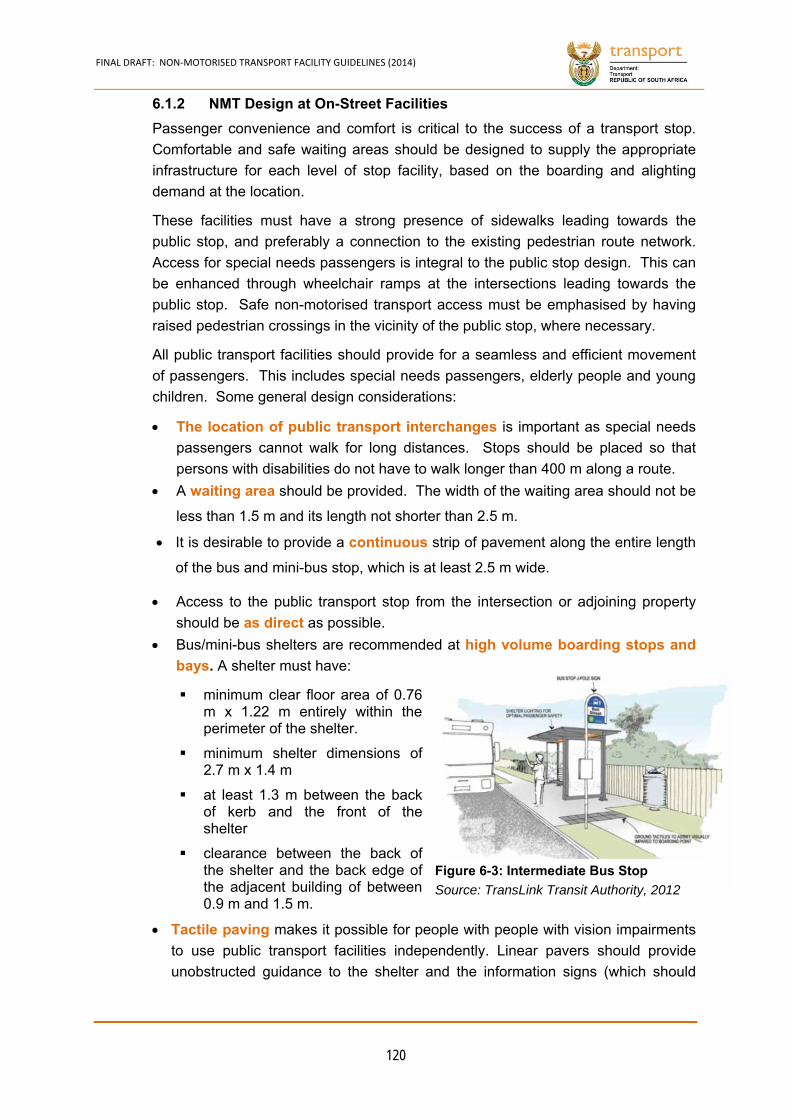
FINAL DRAFT: NON‐MOTORISED TRANSPORT FACILITY GUIDELINES (2014)
120
NMT Design at On-Street Facilities 6.1.2
Passenger convenience and comfort is critical to the success of a transport stop.
Comfortable and safe waiting areas should be designed to supply the appropriate
infrastructure for each level of stop facility, based on the boarding and alighting
demand at the location.
These facilities must have a strong presence of sidewalks leading towards the
public stop, and preferably a connection to the existing pedestrian route network.
Access for special needs passengers is integral to the public stop design. This can
be enhanced through wheelchair ramps at the intersections leading towards the
public stop. Safe non-motorised transport access must be emphasised by having
raised pedestrian crossings in the vicinity of the public stop, where necessary.
All public transport facilities should provide for a seamless and efficient movement
of passengers. This includes special needs passengers, elderly people and young
children. Some general design considerations:
The location of public transport interchanges is important as special needs
passengers cannot walk for long distances. Stops should be placed so that
persons with disabilities do not have to walk longer than 400 m along a route.
A waiting area should be provided. The width of the waiting area should not be
less than 1.5 m and its length not shorter than 2.5 m.
It is desirable to provide a continuous strip of pavement along the entire length
of the bus and mini-bus stop, which is at least 2.5 m wide.
Access to the public transport stop from the intersection or adjoining property
should be as direct as possible.
Bus/mini-bus shelters are recommended at high volume boarding stops and
bays. A shelter must have:
minimum clear floor area of 0.76 m x 1.22 m entirely within the perimeter of the shelter.
minimum shelter dimensions of 2.7 m x 1.4 m
at least 1.3 m between the back of kerb and the front of the shelter
clearance between the back of the shelter and the back edge of the adjacent building of between 0.9 m and 1.5 m.
Tactile paving makes it possible for people with people with vision impairments
to use public transport facilities independently. Linear pavers should provide
unobstructed guidance to the shelter and the information signs (which should
Figure 6-3: Intermediate Bus Stop
Source: TransLink Transit Authority, 2012
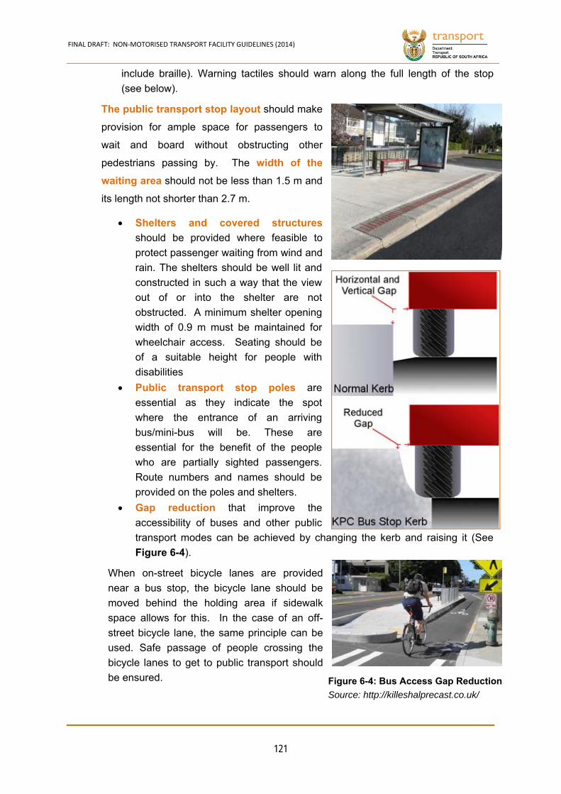
FINAL DRAFT: NON‐MOTORISED TRANSPORT FACILITY GUIDELINES (2014)
121
include braille). Warning tactiles should warn along the full length of the stop
(see below).
The public transport stop layout should make
provision for ample space for passengers to
wait and board without obstructing other
pedestrians passing by. The width of the
waiting area should not be less than 1.5 m and
its length not shorter than 2.7 m.
Shelters and covered structures
should be provided where feasible to
protect passenger waiting from wind and
rain. The shelters should be well lit and
constructed in such a way that the view
out of or into the shelter are not
obstructed. A minimum shelter opening
width of 0.9 m must be maintained for
wheelchair access. Seating should be
of a suitable height for people with
disabilities
Public transport stop poles are
essential as they indicate the spot
where the entrance of an arriving
bus/mini-bus will be. These are
essential for the benefit of the people
who are partially sighted passengers.
Route numbers and names should be
provided on the poles and shelters.
Gap reduction that improve the
accessibility of buses and other public
transport modes can be achieved by changing the kerb and raising it (See
Figure 6-4).
When on-street bicycle lanes are provided
near a bus stop, the bicycle lane should be
moved behind the holding area if sidewalk
space allows for this. In the case of an off-
street bicycle lane, the same principle can be
used. Safe passage of people crossing the
bicycle lanes to get to public transport should
be ensured. Figure 6-4: Bus Access Gap Reduction
Source: http://killeshalprecast.co.uk/
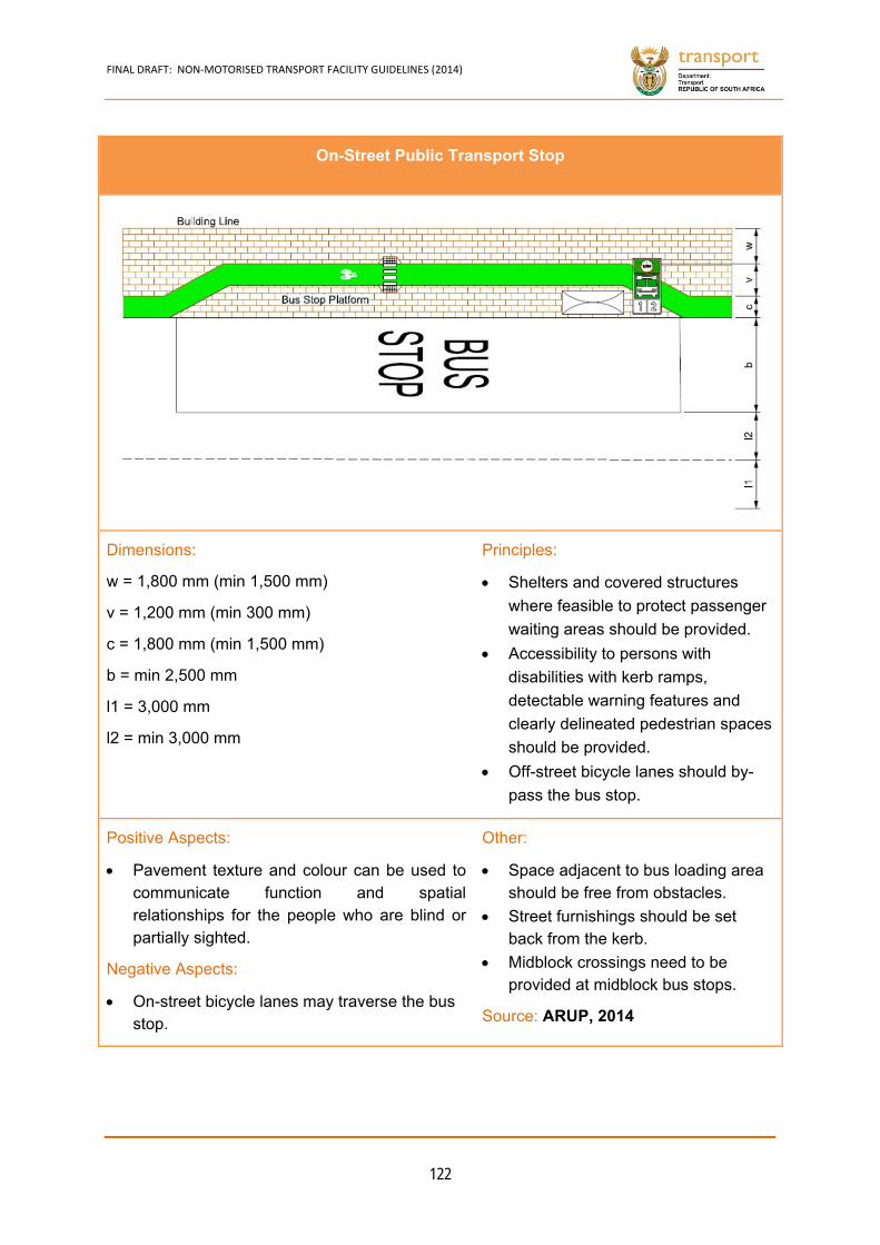
FINAL DRAFT: NON‐MOTORISED TRANSPORT FACILITY GUIDELINES (2014)
122
On-Street Public Transport Stop
Dimensions:
w = 1,800 mm (min 1,500 mm)
v = 1,200 mm (min 300 mm)
c = 1,800 mm (min 1,500 mm)
b = min 2,500 mm
l1 = 3,000 mm
l2 = min 3,000 mm
Principles:
Shelters and covered structures
where feasible to protect passenger
waiting areas should be provided.
Accessibility to persons with
disabilities with kerb ramps,
detectable warning features and
clearly delineated pedestrian spaces
should be provided.
Off-street bicycle lanes should by-
pass the bus stop.
Positive Aspects:
Pavement texture and colour can be used to communicate function and spatial relationships for the people who are blind or partially sighted.
Negative Aspects:
On-street bicycle lanes may traverse the bus stop.
Other:
Space adjacent to bus loading area should be free from obstacles.
Street furnishings should be set back from the kerb.
Midblock crossings need to be provided at midblock bus stops.
Source: ARUP, 2014
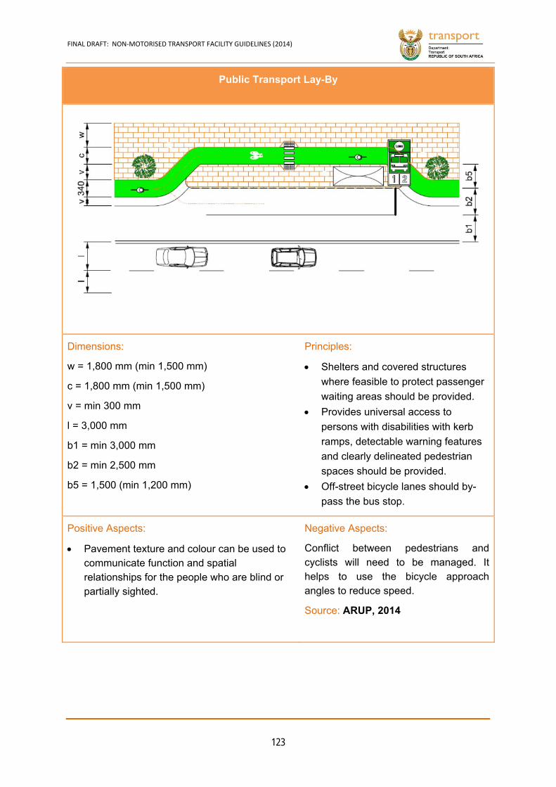
FINAL DRAFT: NON‐MOTORISED TRANSPORT FACILITY GUIDELINES (2014)
123
Public Transport Lay-By
Dimensions:
w = 1,800 mm (min 1,500 mm)
c = 1,800 mm (min 1,500 mm)
v = min 300 mm
l = 3,000 mm
b1 = min 3,000 mm
b2 = min 2,500 mm
b5 = 1,500 (min 1,200 mm)
Principles:
Shelters and covered structures
where feasible to protect passenger
waiting areas should be provided.
Provides universal access to
persons with disabilities with kerb
ramps, detectable warning features
and clearly delineated pedestrian
spaces should be provided.
Off-street bicycle lanes should by-
pass the bus stop.
Positive Aspects:
Pavement texture and colour can be used to communicate function and spatial relationships for the people who are blind or partially sighted.
Negative Aspects:
Conflict between pedestrians and cyclists will need to be managed. It helps to use the bicycle approach angles to reduce speed.
Source: ARUP, 2014
FINAL DRAFT: NON‐MOTORISED TRANSPORT FACILITY GUIDELINES (2014)
124
Median Public Transport Stations 6.1.3
In the last few decades, Bus Rapid Transit (BRT) has emerged as a cost-effective,
flexible and environmentally sustainable form of public transportation. The world’s
first BRT was developed in Curitiba, Brazil, which was followed by the development
of many other BRTs across South African Cities. The term BRT has come to
represent a wide range of bus-based, public transportation systems. Although these
systems have commonalities, they may also have some very different features.
Often, it is the decision of which BRT feature to include or exclude that determines
the success or failure of the system (Road Safety Design Guidelines for BRT in
Indian Cities, 2012).
Design Principles
A minimum station platform width of 5 m and a minimum entrance length of 15 m
to allow for inclusion of ticket kiosks, server rooms, staff ablutions and access
control systems.
Access to a double sided off a signalised intersection, with space provided for
universal access features (ramps). The tactile paving to the BRT stations
should be pronounced, multi-toned and continuously clear. Tactile paving
should be added to all stairs and pedestrian bridges.
There should be a full array of NMT facilities along the main trunk line of the
BRT. A minimum sidewalk width of 3 m for urban corridors with extensive
development is encouraged, with a minimum of 1.5 m for bicycle lanes along
the corridor. Adequate space must be provided within the station precinct for
bicycle parking facilities. There should be no obstacles in the path of travel,
seating and shelter/landscaping should provide a decent waling environment.
Traffic signal poles need to be pulled back to the near side pedestrian
crossing line to ensure that the signal poles are no more than 3 m from the stop
line. Pedestrian buttons should be located on the pedestrian signal pole.
Staggered crossings are more favourable and preferred as they allow greater
visibility of the pedestrian crossings at the intersection exit carriageways (and
the opposing turning traffic will be moving more slowly at the pedestrian
crossing point).

FINAL DRAFT: NON‐MOTORISED TRANSPORT FACILITY GUIDELINES (2014)
125
NMT at Median Public Transport Station
Dimensions:
Site dependent
Principles:
All modes of transport are accommodated.
Pedestrian crossings preferably have
discriminating paving materials/colours.
Adequate crossing time at signals is
required.
Adequate queuing space on refuge islands
is needed.
If pedestrian flows are very high, staggering
of crossing facilities (See staggered
midblock facilities) can be considered.
Channelise pedestrian movement to
crossings and using tactile pavers.
Proper lightings need to be provided at
crossings.
If the bicycle lane is on street, bike boxes
need to be installed at intersections.
Painted or dyed surfaces are
recommended, also at the intersection.
Principles (cont.):
To promote bicycle and public
transport integration, bicycle
parking needs to be
accommodated.
Provision of travel option on bus
with bicycle is welcomed.
www.mediagallery.usatoday.com
Source: GIBB, 2010
FINAL DRAFT: NON‐MOTORISED TRANSPORT FACILITY GUIDELINES (2014)
126
6.2 Bicycle Parking
Good quality bicycle parking is a key element in developing a bicycle-friendly
environment. The absence of secure, convenient bicycle parking can be a serious
deterrent to bicycle use. Bicycle parking should be provided at major destinations,
public buildings, schools and colleges, hospitals, large employment sites, public
transport interchanges and leisure attractions.
Proximity to the destination is the major influence on a cyclist’s choice of where to
park (Taylor and Halliday, 1997), regardless of the journey purpose. The use of the
bicycle as a feeder to public transport can also be a valuable component of a
strategy to encourage more people to bike (Taylor, 1996).
Principles of Bicycle Parking Location 6.2.1
Bicycle racks should be permanently affixed to a paved surface, and must be
installed in an orderly and neat appearance.
Bicycle parking facilities should also be encouraged at schools, buildings, public
transport facilities and universities within any urban area. Short-term parking
facilities should be provided near all IPTN stations and other multi modal
interchanges, PRASA, Gautrain stations and municipalities.
Bicycle parking facilities should not obstruct the pedestrian walkways but be
located within the vicinity of each public transport station and should be placed
outside the accessible path of travel.
Bicycle parking facilities should be easy to find and as close to destinations
as practicable. Numerous small clusters of stands throughout the city are
generally preferable to one large parking area.
Cycling facilities should be fit for purpose and easy to use. Stands that
support the bicycle by gripping the front wheel alone should be avoided,
because of the damage they can cause.
Stands should have sufficient space around them to ensure they are
convenient to gain access to (parallel stands should be at least one metre
apart, for example).
Public transport interchanges, places popular with tourists and other such
attractors should be provided with bicycle parking facilities appropriate to
demand.
Long-term parking for regular users should ideally be within a secure access
area and protected from the weather. The level of weather protection for
other parking should be appropriate for the length of stay.
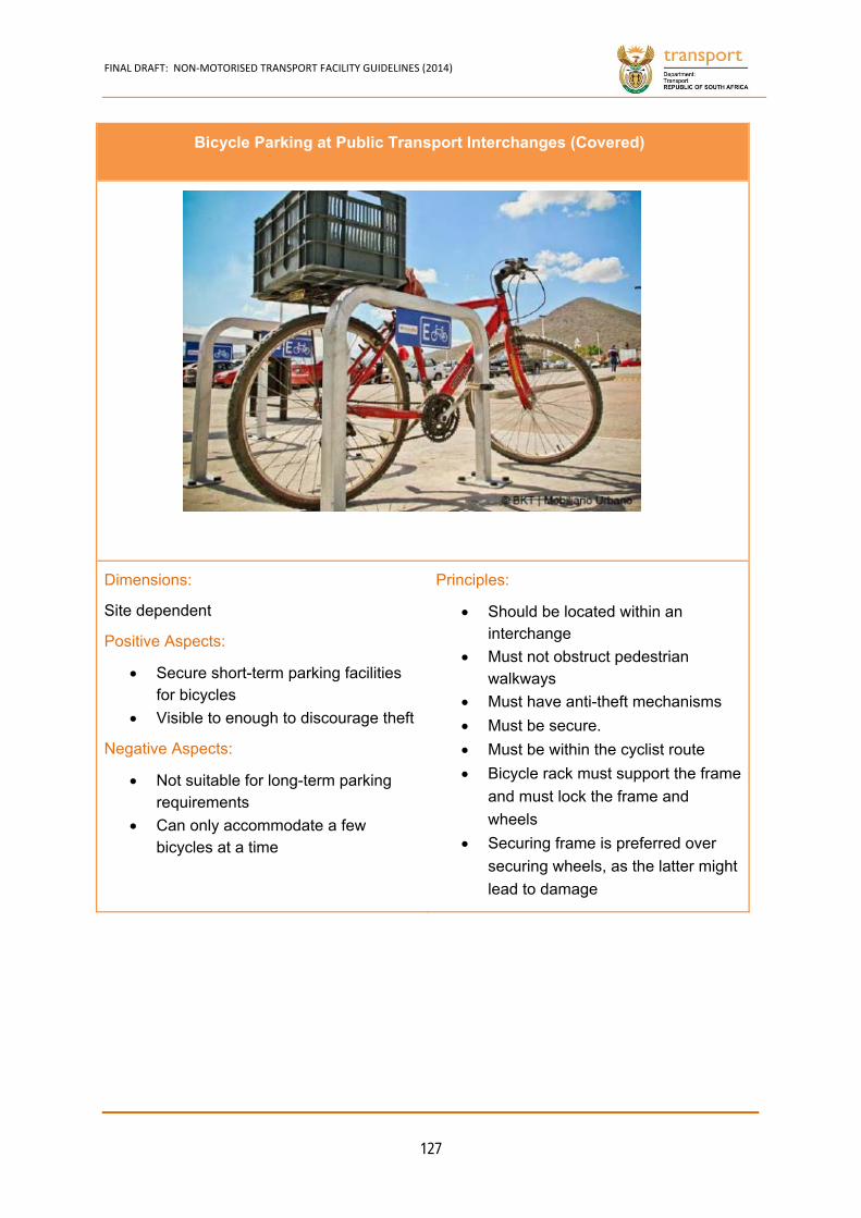
FINAL DRAFT: NON‐MOTORISED TRANSPORT FACILITY GUIDELINES (2014)
127
Bicycle Parking at Public Transport Interchanges (Covered)
Dimensions:
Site dependent
Positive Aspects:
Secure short-term parking facilities for bicycles
Visible to enough to discourage theft
Negative Aspects:
Not suitable for long-term parking requirements
Can only accommodate a few bicycles at a time
Principles:
Should be located within an interchange
Must not obstruct pedestrian walkways
Must have anti-theft mechanisms
Must be secure.
Must be within the cyclist route
Bicycle rack must support the frame
and must lock the frame and
wheels
Securing frame is preferred over
securing wheels, as the latter might
lead to damage
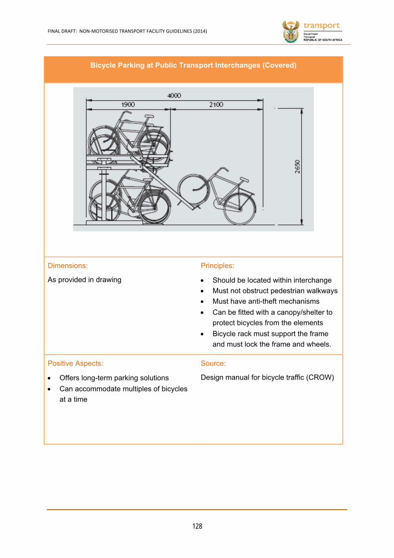
FINAL DRAFT: NON‐MOTORISED TRANSPORT FACILITY GUIDELINES (2014)
128
Bicycle Parking at Public Transport Interchanges (Covered)
Dimensions:
As provided in drawing
Principles:
Should be located within interchange
Must not obstruct pedestrian walkways
Must have anti-theft mechanisms
Can be fitted with a canopy/shelter to
protect bicycles from the elements
Bicycle rack must support the frame
and must lock the frame and wheels.
Positive Aspects:
Offers long-term parking solutions
Can accommodate multiples of bicycles
at a time
Source:
Design manual for bicycle traffic (CROW)
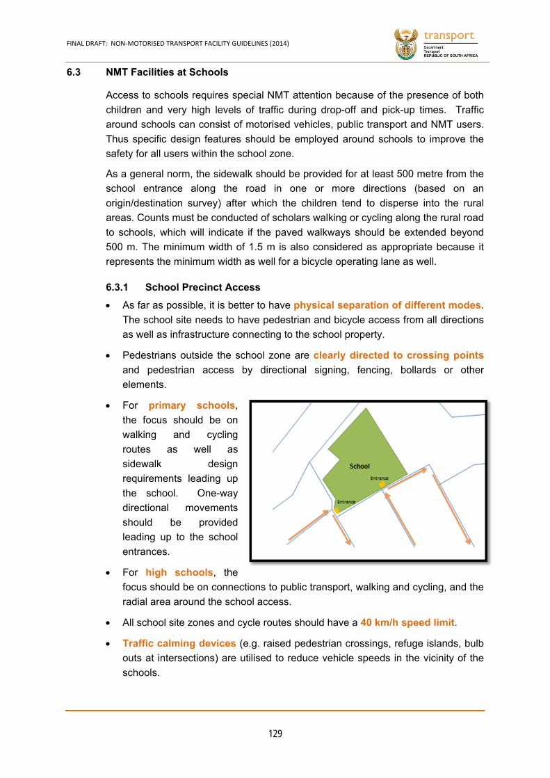
FINAL DRAFT: NON‐MOTORISED TRANSPORT FACILITY GUIDELINES (2014)
129
6.3 NMT Facilities at Schools
Access to schools requires special NMT attention because of the presence of both
children and very high levels of traffic during drop-off and pick-up times. Traffic
around schools can consist of motorised vehicles, public transport and NMT users.
Thus specific design features should be employed around schools to improve the
safety for all users within the school zone.
As a general norm, the sidewalk should be provided for at least 500 metre from the
school entrance along the road in one or more directions (based on an
origin/destination survey) after which the children tend to disperse into the rural
areas. Counts must be conducted of scholars walking or cycling along the rural road
to schools, which will indicate if the paved walkways should be extended beyond
500 m. The minimum width of 1.5 m is also considered as appropriate because it
represents the minimum width as well for a bicycle operating lane as well.
School Precinct Access 6.3.1
As far as possible, it is better to have physical separation of different modes.
The school site needs to have pedestrian and bicycle access from all directions
as well as infrastructure connecting to the school property.
Pedestrians outside the school zone are clearly directed to crossing points
and pedestrian access by directional signing, fencing, bollards or other
elements.
For primary schools,
the focus should be on
walking and cycling
routes as well as
sidewalk design
requirements leading up
the school. One-way
directional movements
should be provided
leading up to the school
entrances.
For high schools, the
focus should be on connections to public transport, walking and cycling, and the
radial area around the school access.
All school site zones and cycle routes should have a 40 km/h speed limit.
Traffic calming devices (e.g. raised pedestrian crossings, refuge islands, bulb
outs at intersections) are utilised to reduce vehicle speeds in the vicinity of the
schools.
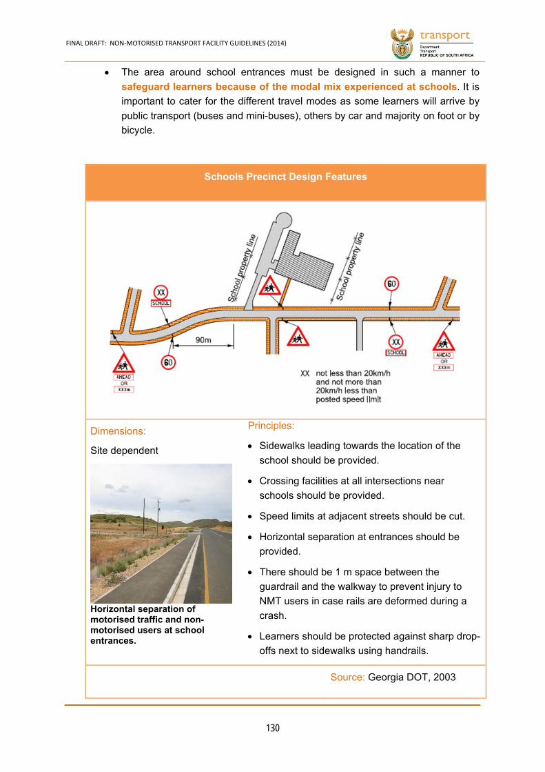
FINAL DRAFT: NON‐MOTORISED TRANSPORT FACILITY GUIDELINES (2014)
130
The area around school entrances must be designed in such a manner to
safeguard learners because of the modal mix experienced at schools. It is
important to cater for the different travel modes as some learners will arrive by
public transport (buses and mini-buses), others by car and majority on foot or by
bicycle.
Schools Precinct Design Features
Dimensions:
Site dependent
Horizontal separation of motorised traffic and non-motorised users at school entrances.
Principles:
Sidewalks leading towards the location of the
school should be provided.
Crossing facilities at all intersections near
schools should be provided.
Speed limits at adjacent streets should be cut.
Horizontal separation at entrances should be
provided.
There should be 1 m space between the
guardrail and the walkway to prevent injury to
NMT users in case rails are deformed during a
crash.
Learners should be protected against sharp drop-
offs next to sidewalks using handrails.
Source: Georgia DOT, 2003
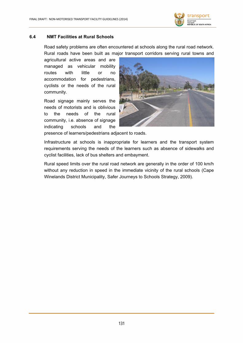
FINAL DRAFT: NON‐MOTORISED TRANSPORT FACILITY GUIDELINES (2014)
131
6.4 NMT Facilities at Rural Schools
Road safety problems are often encountered at schools along the rural road network.
Rural roads have been built as major transport corridors serving rural towns and
agricultural active areas and are
managed as vehicular mobility
routes with little or no
accommodation for pedestrians,
cyclists or the needs of the rural
community.
Road signage mainly serves the
needs of motorists and is oblivious
to the needs of the rural
community, i.e. absence of signage
indicating schools and the
presence of learners/pedestrians adjacent to roads.
Infrastructure at schools is inappropriate for learners and the transport system
requirements serving the needs of the learners such as absence of sidewalks and
cyclist facilities, lack of bus shelters and embayment.
Rural speed limits over the rural road network are generally in the order of 100 km/h
without any reduction in speed in the immediate vicinity of the rural schools (Cape
Winelands District Municipality, Safer Journeys to Schools Strategy, 2009).
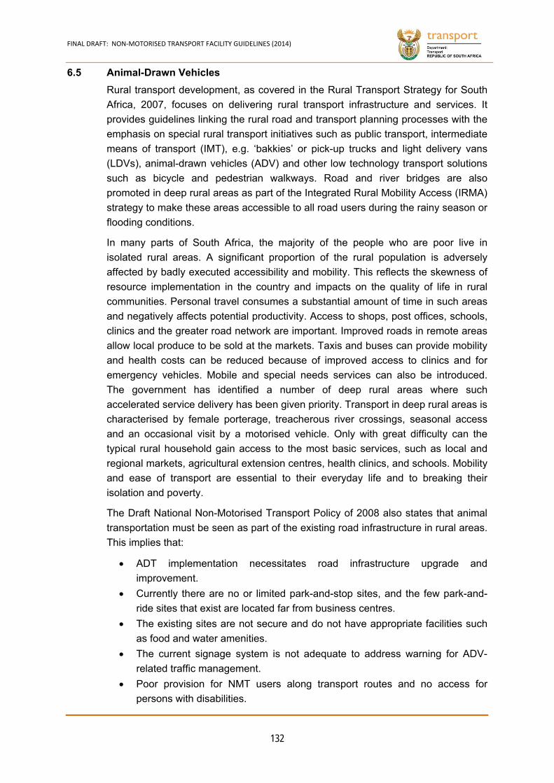
FINAL DRAFT: NON‐MOTORISED TRANSPORT FACILITY GUIDELINES (2014)
132
6.5 Animal-Drawn Vehicles
Rural transport development, as covered in the Rural Transport Strategy for South
Africa, 2007, focuses on delivering rural transport infrastructure and services. It
provides guidelines linking the rural road and transport planning processes with the
emphasis on special rural transport initiatives such as public transport, intermediate
means of transport (IMT), e.g. ‘bakkies’ or pick-up trucks and light delivery vans
(LDVs), animal-drawn vehicles (ADV) and other low technology transport solutions
such as bicycle and pedestrian walkways. Road and river bridges are also
promoted in deep rural areas as part of the Integrated Rural Mobility Access (IRMA)
strategy to make these areas accessible to all road users during the rainy season or
flooding conditions.
In many parts of South Africa, the majority of the people who are poor live in
isolated rural areas. A significant proportion of the rural population is adversely
affected by badly executed accessibility and mobility. This reflects the skewness of
resource implementation in the country and impacts on the quality of life in rural
communities. Personal travel consumes a substantial amount of time in such areas
and negatively affects potential productivity. Access to shops, post offices, schools,
clinics and the greater road network are important. Improved roads in remote areas
allow local produce to be sold at the markets. Taxis and buses can provide mobility
and health costs can be reduced because of improved access to clinics and for
emergency vehicles. Mobile and special needs services can also be introduced.
The government has identified a number of deep rural areas where such
accelerated service delivery has been given priority. Transport in deep rural areas is
characterised by female porterage, treacherous river crossings, seasonal access
and an occasional visit by a motorised vehicle. Only with great difficulty can the
typical rural household gain access to the most basic services, such as local and
regional markets, agricultural extension centres, health clinics, and schools. Mobility
and ease of transport are essential to their everyday life and to breaking their
isolation and poverty.
The Draft National Non-Motorised Transport Policy of 2008 also states that animal
transportation must be seen as part of the existing road infrastructure in rural areas.
This implies that:
ADT implementation necessitates road infrastructure upgrade and
improvement.
Currently there are no or limited park-and-stop sites, and the few park-and-
ride sites that exist are located far from business centres.
The existing sites are not secure and do not have appropriate facilities such
as food and water amenities.
The current signage system is not adequate to address warning for ADV-
related traffic management.
Poor provision for NMT users along transport routes and no access for
persons with disabilities.
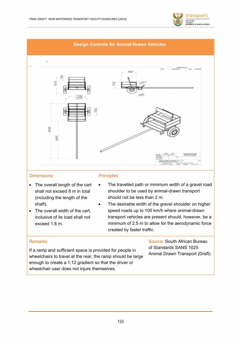
FINAL DRAFT: NON‐MOTORISED TRANSPORT FACILITY GUIDELINES (2014)
133
Design Controls for Animal-Drawn Vehicles
. norma lly re
Dimensions:
The overall length of the cart
shall not exceed 8 m in total
(including the length of the
shaft).
The overall width of the cart,
inclusive of its load shall not
exceed 1.8 m.
Principles:
The travelled path or minimum width of a gravel road
shoulder to be used by animal-drawn transport
should not be less than 2 m.
The desirable width of the gravel shoulder on higher
speed roads up to 100 km/h where animal-drawn
transport vehicles are present should, however, be a
minimum of 2.5 m to allow for the aerodynamic force
created by faster traffic.
Remarks:
If a ramp and sufficient space is provided for people in wheelchairs to travel at the rear, the ramp should be large enough to create a 1:12 gradient so that the driver or wheelchair user does not injure themselves.
Source: South African Bureau of Standards SANS 1025 Animal Drawn Transport (Draft)
FINAL DRAFT: NON‐MOTORISED TRANSPORT FACILITY GUIDELINES (2014)
134
Geometric Design Elements of Roads 6.5.1
(a) Road Access and Usage
The Department of Transport policy document, titled “An Animal Drawn Transportation Policy for South Africa”, 2007, states that because the integration of access points to main roads should be the subject of careful planning, animal-drawn vehicles shall have identified spots where they enter the main road and their access points may be different from those of motor vehicles depending on the volume of traffic and the speed limitations of those access points. Furthermore, no animal transportation shall be allowed on the national freeways and provincial roads/highways where speed limits are between 100 and 120 km per hour.
(b) Road Shoulders of Paved Rural Roads
The South African Bureau of Standards SANS 1025 specifies that the overall width of animal-drawn vehicles, inclusive of their load, shall not exceed 1.8 m. This implies that the travelled lane or minimum width of a gravel road shoulder to be used by animal-drawn transport should be 2.0 m. However, the desirable width of the gravel shoulder on higher speed roads up to 100 km/h, where animal-drawn vehicles are present, should rather be from 2.5 m to 3.0 m to allow for some clearance space between the animal-drawn transport on the gravel shoulder and the aerodynamic force of passing vehicles.
Consideration needs to be given to the movement of animal-drawn vehicles either along or across rural roads. Measurements or estimates of such movements should be made, where possible, to give a firmer basis for making decisions on the design. Some guidelines from TRL Overseas Note 6: A Guide to Geometric Design regarding road shoulder usage for animal-drawn vehicles and other means of non-motorised transport are:
At very low flows of motorised traffic, the problem of interaction is likely to be small. However, care must be taken to ensure that adequate sight distances and/or warnings are given to a driver as he approaches any area of high activity such as a village.
As flows become greater, the conflicts between slow and fast moving traffic will increase and additional widths of both shoulder and running surface may be necessary. The increase in width will vary with the relative amounts of traffic, their characteristics and the terrain and needs of the road. In view of the relatively high costs normally involved in widening, care should be taken to ensure that only those sections of shoulder are widened which are justified by local demand.
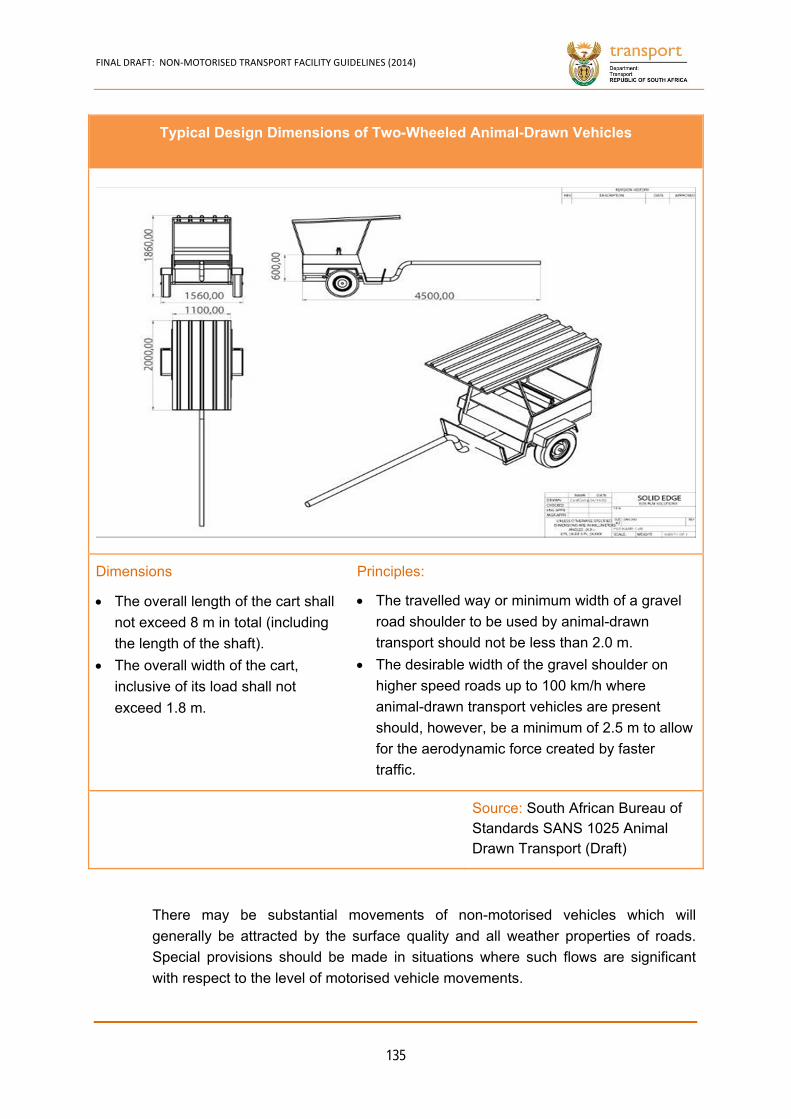
FINAL DRAFT: NON‐MOTORISED TRANSPORT FACILITY GUIDELINES (2014)
135
There may be substantial movements of non-motorised vehicles which will
generally be attracted by the surface quality and all weather properties of roads.
Special provisions should be made in situations where such flows are significant
with respect to the level of motorised vehicle movements.
Typical Design Dimensions of Two-Wheeled Animal-Drawn Vehicles
norma lly re
Dimensions
The overall length of the cart shall
not exceed 8 m in total (including
the length of the shaft).
The overall width of the cart,
inclusive of its load shall not
exceed 1.8 m.
Principles:
The travelled way or minimum width of a gravel
road shoulder to be used by animal-drawn
transport should not be less than 2.0 m.
The desirable width of the gravel shoulder on
higher speed roads up to 100 km/h where
animal-drawn transport vehicles are present
should, however, be a minimum of 2.5 m to allow
for the aerodynamic force created by faster
traffic.
Source: South African Bureau of Standards SANS 1025 Animal Drawn Transport (Draft)
FINAL DRAFT: NON‐MOTORISED TRANSPORT FACILITY GUIDELINES (2014)
136
Some localised shoulder improvements may be appropriate as non-motorised traffic
generally increases near towns and villages. Where large numbers of non-
motorised transport vehicles or users travel on the shoulders, the following features
are recommended:
Shoulders should be sealed.
Shoulders should be clearly segregated by the use of edge of
carriageway surface markings or other measures.
Special crossing facilities should be provided where possible and
necessary.
On high speed roads with substantial flows of motorised vehicles, non-motorised traffic should be given a separate space segregated by a physical barrier such as a kerb. Crossing movements should also be concentrated at specific locations and special crossing facilities provided. Traffic approaching these facilities should be given adequate warning and stopping sight distances which are greater than minimum values should be provided where possible.
The road shoulder along designated animal-drawn vehicle routes must be regularly maintained, well drained and free of undulations or vegetation. Special care should be taken along road sections where road shoulder width is restricted by fills, cuts or narrow bridge structures, so that animal-drawn vehicles are not endangered by other passing traffic.
(c) Service Roads in Settlements
Animal-drawn vehicles must be restricted to service roads in settlements wherever these roads are available next to or near the main road.
(d) Maximum Grade of Roads
Gradients of 10% or over will usually need to be paved to enable sufficient traction to be achieved, as well as for pavement maintenance reasons. While pedestrian and animal movements are possible on very steep inclines, some laden animal-drawn carts may find steep grades difficult to traverse because of a lack of grip. Such grades, therefore, should not be steeper than 10%. TRL Overseas Note 6: A Guide to Geometric Design, p.20
(e) Horizontal and Vertical Curvature
Special care should be taken by road authorities to ensure that in undulating landscape or mountainous areas, horizontal and vertical sight distances on roads used or crossed by animal-drawn vehicles should comply with accepted geometric design standards.
FINAL DRAFT: NON‐MOTORISED TRANSPORT FACILITY GUIDELINES (2014)
137
ADV Parking Areas in Towns 6.5.2
The Department of Transport policy document, titled “An Animal Drawn
Transportation Policy for South Africa”, 2007, provides the following guidelines with
regard to animal-drawn transport parking areas in towns:
Where possible, towns should provide park and stop sites for the animal-drawn
transport that come to their towns. As the spaces in towns may be limited to
provide such a spaces and sites, the provision of such facilities should be near
the end of the city limits, but not far enough for the people who use this
transportation to walk to and from the inner city.
At this parking site, food water and fodder should be provided for the animals.
However, the food to be provided shall be suitable for the animals and shall be
free of contamination; the water must be separated from the water to be used for
human consumption but shall be potable enough for the health of the animals;
and the fodder shall be what the animals are used to.
Ventilation, if the space is enclosed, shall be provided for the animal parking
places. However, enough care should be given for the animals to have as much
of its natural habitat as possible and not be disturbed by the life of the city
approach.
If the space is enclosed, there should be enough space for the animal to turn
around and sleep and to relax in a manner that will be natural to the animal. The
need for space should not be decided on the availability of space in the city or
town and the costs related to it, but should consider the natural habitat of the
animal concerned.

CHAPTER 7
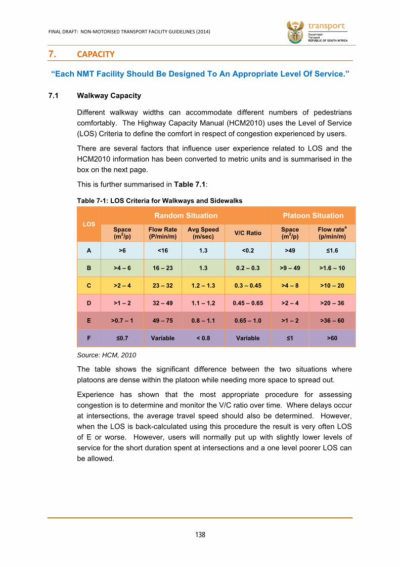
FINAL DRAFT: NON‐MOTORISED TRANSPORT FACILITY GUIDELINES (2014)
138
7. CAPACITY
“Each NMT Facility Should Be Designed To An Appropriate Level Of Service.”
7.1 Walkway Capacity
Different walkway widths can accommodate different numbers of pedestrians
comfortably. The Highway Capacity Manual (HCM2010) uses the Level of Service
(LOS) Criteria to define the comfort in respect of congestion experienced by users.
There are several factors that influence user experience related to LOS and the
HCM2010 information has been converted to metric units and is summarised in the
box on the next page.
This is further summarised in Table 7.1:
LOS Random Situation Platoon Situation
Space (m2/p)
Flow Rate (P/min/m)
Avg Speed (m/sec)
V/C Ratio Space (m2/p)
Flow ratea (p/min/m)
A >6 <16 1.3 <0.2 >49 ≤1.6
B >4 – 6 16 – 23 1.3 0.2 – 0.3 >9 – 49 >1.6 – 10
C >2 – 4 23 – 32 1.2 – 1.3 0.3 – 0.45 >4 – 8 >10 – 20
D >1 – 2 32 – 49 1.1 – 1.2 0.45 – 0.65 >2 – 4 >20 – 36
E >0.7 – 1 49 – 75 0.8 – 1.1 0.65 – 1.0 >1 – 2 >36 – 60
F ≤0.7 Variable < 0.8 Variable ≤1 >60
Source: HCM, 2010
The table shows the significant difference between the two situations where
platoons are dense within the platoon while needing more space to spread out.
Experience has shown that the most appropriate procedure for assessing
congestion is to determine and monitor the V/C ratio over time. Where delays occur
at intersections, the average travel speed should also be determined. However,
when the LOS is back-calculated using this procedure the result is very often LOS
of E or worse. However, users will normally put up with slightly lower levels of
service for the short duration spent at intersections and a one level poorer LOS can
be allowed.
Table 7-1: LOS Criteria for Walkways and Sidewalks
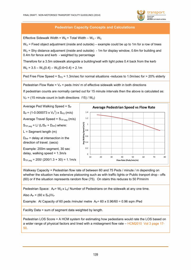
FINAL DRAFT: NON‐MOTORISED TRANSPORT FACILITY GUIDELINES (2014)
139
Pedestrian Capacity Concepts and Calculations
Effective Sidewalk Width = WE = Total Width – WO - WS
WO = Fixed object adjustment (inside and outside) – example could be up to 1m for a row of trees
WS = Shy distance adjusment (inside and outside) - 1m for display window, 0.6m for building and 0.4m for fence and kerb - weighted by percentage
Therefore for a 3.5m sidewalk alongside a building/wall with light poles 0.4 back from the kerb
WE = 3.5 – WO{0.4} – WS{0.6+0.4} = 2.1m
Ped Free Flow Speed = SFS = 1.3m/sec for normal situations -reduces to 1.0m/sec for > 20% elderly
Pedestrian Flow Rate = VP = peds /min/ m of effective sidewalk width in both directions
If pedestrian counts are normally carried out for 15 minute intervals then the above is calculated as:
VP = (15 minute count in both directions /15) / WE)
Average Ped Walking Speed = SP
SP = (1-0.000073 x VP2) x SFS (m/s)
Average Travel Speed = STP,seg (m/s)
STP,seg = L/ (L/SP + DPP) where:
L = Segment length (m)
DPP = delay at intersection in the direction of travel. (secs)
Example: 200m segment, 30 sec delay, walking speed = 1.3m/s
STP,seg = 200/ (200/1.3 + 30) = 1.1m/s
Walkway Capacity = Pedestrian flow rate of between 60 and 75 Peds / minute / m depending on whether the situation has extensive platooning such as with traffic lights or Public tranport drop - offs (60) or if the situation represents random flow (75). On stairs this reduces to 50 P/min/m
Pedestrian Space: AP= WE x LE/ Number of Pedestrians on the sidewalk at any one time.
Also AP = (60 x SP)/VP
Example: At Capacity of 60 peds /minute/ metre AP= 60 x 0.96/60 = 0.96 sqm /Ped
Facility Data = sum of segment data weighted by length.
Pedestrian LOS Score = A HCM system for estimating how pedestians would rate the LOS based on a wider range of physical factors and lined with a midsegment flow rate – HCM2010 Vol 3 page 17-50.
0
0.2
0.4
0.6
0.8
1
1.2
1.4
10 20 30 40 50 60 70 80
Avg W
alking Speed (m/s)
Flow Rate (Peds/min/m)
Average Pedestrian Speed vs Flow Rate
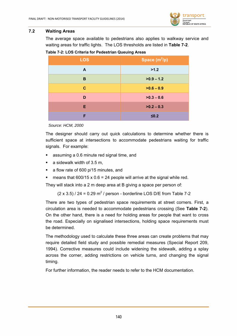
FINAL DRAFT: NON‐MOTORISED TRANSPORT FACILITY GUIDELINES (2014)
140
7.2 Waiting Areas
The average space available to pedestrians also applies to walkway service and
waiting areas for traffic lights. The LOS thresholds are listed in Table 7-2.
LOS Space (m2/p)
A >1.2
B >0.9 – 1.2
C >0.6 – 0.9
D >0.3 – 0.6
E >0.2 – 0.3
F ≤0.2
Source: HCM, 2000
The designer should carry out quick calculations to determine whether there is
sufficient space at intersections to accommodate pedestrians waiting for traffic
signals. For example:
assuming a 0.6 minute red signal time, and
a sidewalk width of 3.5 m,
a flow rate of 600 p/15 minutes, and
means that 600/15 x 0.6 = 24 people will arrive at the signal while red.
They will stack into a 2 m deep area at B giving a space per person of:
(2 x 3.5) / 24 = 0.29 m2 / person - borderline LOS D/E from Table 7-2
There are two types of pedestrian space requirements at street corners. First, a
circulation area is needed to accommodate pedestrians crossing (See Table 7-2).
On the other hand, there is a need for holding areas for people that want to cross
the road. Especially on signalised intersections, holding space requirements must
be determined.
The methodology used to calculate these three areas can create problems that may
require detailed field study and possible remedial measures (Special Report 209,
1994). Corrective measures could include widening the sidewalk, adding a splay
across the corner, adding restrictions on vehicle turns, and changing the signal
timing.
For further information, the reader needs to refer to the HCM documentation.
Table 7-2: LOS Criteria for Pedestrian Queuing Areas
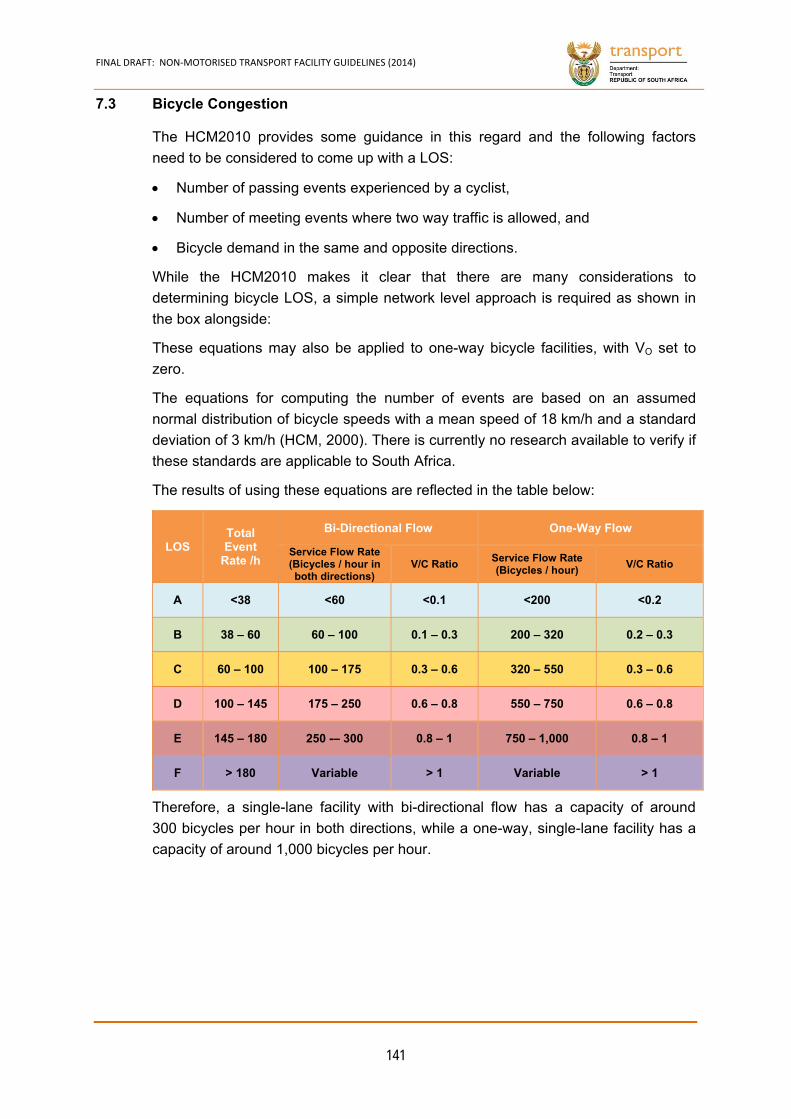
FINAL DRAFT: NON‐MOTORISED TRANSPORT FACILITY GUIDELINES (2014)
141
7.3 Bicycle Congestion
The HCM2010 provides some guidance in this regard and the following factors
need to be considered to come up with a LOS:
Number of passing events experienced by a cyclist,
Number of meeting events where two way traffic is allowed, and
Bicycle demand in the same and opposite directions.
While the HCM2010 makes it clear that there are many considerations to
determining bicycle LOS, a simple network level approach is required as shown in
the box alongside:
These equations may also be applied to one-way bicycle facilities, with VO set to
zero.
The equations for computing the number of events are based on an assumed
normal distribution of bicycle speeds with a mean speed of 18 km/h and a standard
deviation of 3 km/h (HCM, 2000). There is currently no research available to verify if
these standards are applicable to South Africa.
The results of using these equations are reflected in the table below:
LOS Total Event
Rate /h
Bi-Directional Flow One-Way Flow
Service Flow Rate (Bicycles / hour in both directions)
V/C Ratio Service Flow Rate (Bicycles / hour)
V/C Ratio
A <38 <60 <0.1 <200 <0.2
B 38 – 60 60 – 100 0.1 – 0.3 200 – 320 0.2 – 0.3
C 60 – 100 100 – 175 0.3 – 0.6 320 – 550 0.3 – 0.6
D 100 – 145 175 – 250 0.6 – 0.8 550 – 750 0.6 – 0.8
E 145 – 180 250 -– 300 0.8 – 1 750 – 1,000 0.8 – 1
F > 180 Variable > 1 Variable > 1
Therefore, a single-lane facility with bi-directional flow has a capacity of around
300 bicycles per hour in both directions, while a one-way, single-lane facility has a
capacity of around 1,000 bicycles per hour.
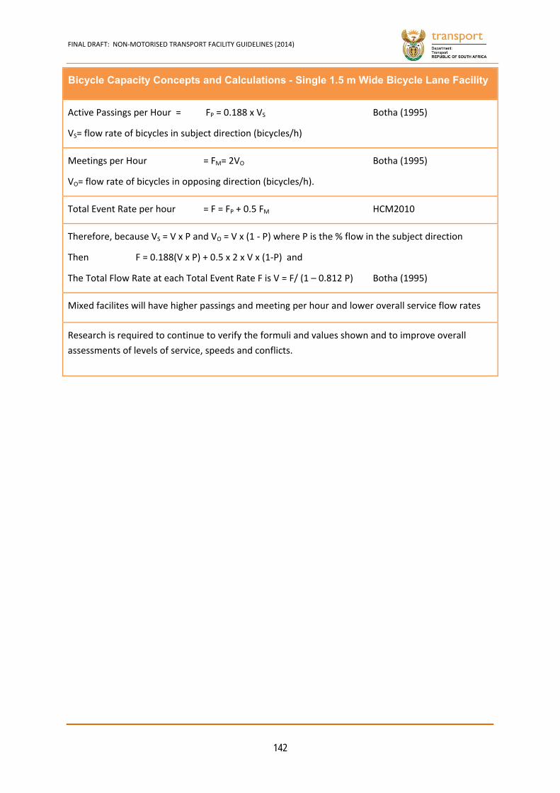
FINAL DRAFT: NON‐MOTORISED TRANSPORT FACILITY GUIDELINES (2014)
142
Bicycle Capacity Concepts and Calculations - Single 1.5 m Wide Bicycle Lane Facility
Active Passings per Hour = FP = 0.188 x VS Botha (1995)
VS= flow rate of bicycles in subject direction (bicycles/h)
Meetings per Hour = FM= 2VO Botha (1995)
VO= flow rate of bicycles in opposing direction (bicycles/h).
Total Event Rate per hour = F = FP + 0.5 FM HCM2010
Therefore, because VS = V x P and VO = V x (1 ‐ P) where P is the % flow in the subject direction
Then F = 0.188(V x P) + 0.5 x 2 x V x (1‐P) and
The Total Flow Rate at each Total Event Rate F is V = F/ (1 – 0.812 P) Botha (1995)
Mixed facilites will have higher passings and meeting per hour and lower overall service flow rates
Research is required to continue to verify the formuli and values shown and to improve overall
assessments of levels of service, speeds and conflicts.

CHAPTER 8
FINAL DRAFT: NON‐MOTORISED TRANSPORT FACILITY GUIDELINES (2014)
143
8. NMT PAVEMENT DESIGN
“The Road To Good NMT Facilities Is Paved Using Appropriate Material.”
8.1 Introduction
South Africa has significant pedestrian movements in most areas. To maintain and
support the growth in the pedestrian demand levels in the country, walkway and
crossing facilities need to be comfortable and safe.
Surface finishes and the underlying pavement are an important element in creating
appropriate NMT mobility routes and access to services. Requirements for the
realisation of appropriate NMT surfaces include:
Smooth and even surfaces
Stable pavement structures
Sufficient surface friction/traction
Obstruction free
Well drained
Appropriate sight lines with clear signage and road furniture
A welcoming ambiance.
When selecting surfacing materials, user requirements need to be matched to
available local materials, budget constraints and maintenance requirements.
Although NMT facilities do not carry heavy traffic, the in-situ soil need to be
prepared thoroughly to provide adequate support and prevent deformation over
time.
Although this chapter refers to maintenance, it is only referenced in terms of the
ease with which the surfacing can be maintained and whether or not the materials
can be re-used. Lack of maintenance resulting in uneven surfaces, missing pavers
and the like can cause hazardous environment for NMT users and is addressed in
Chapter 9.
Many different materials can be used to surface NMT facilities and these are shown
in the following box. The South African Pavement Engineering Manual (SAPEM),
COLTO standard specifications, SANS 10400 Part S, and manufacturers guidelines
all need to be used when designing and constructing paved surfacings.
Uneven surfaces, steps with irregular risers or open risers on flights of stairs are
likely to cause persons with visual impairments to trip and injure themselves.
Quality of workmanship is extremely important in avoiding gaps between surface
finishes, raised thresholds, and to ensure that all steps have uniform risers.
Environments should be well managed to avoid hazards developing, such as those
caused by the disintegration of a surface, or vegetation growing over a pathway.
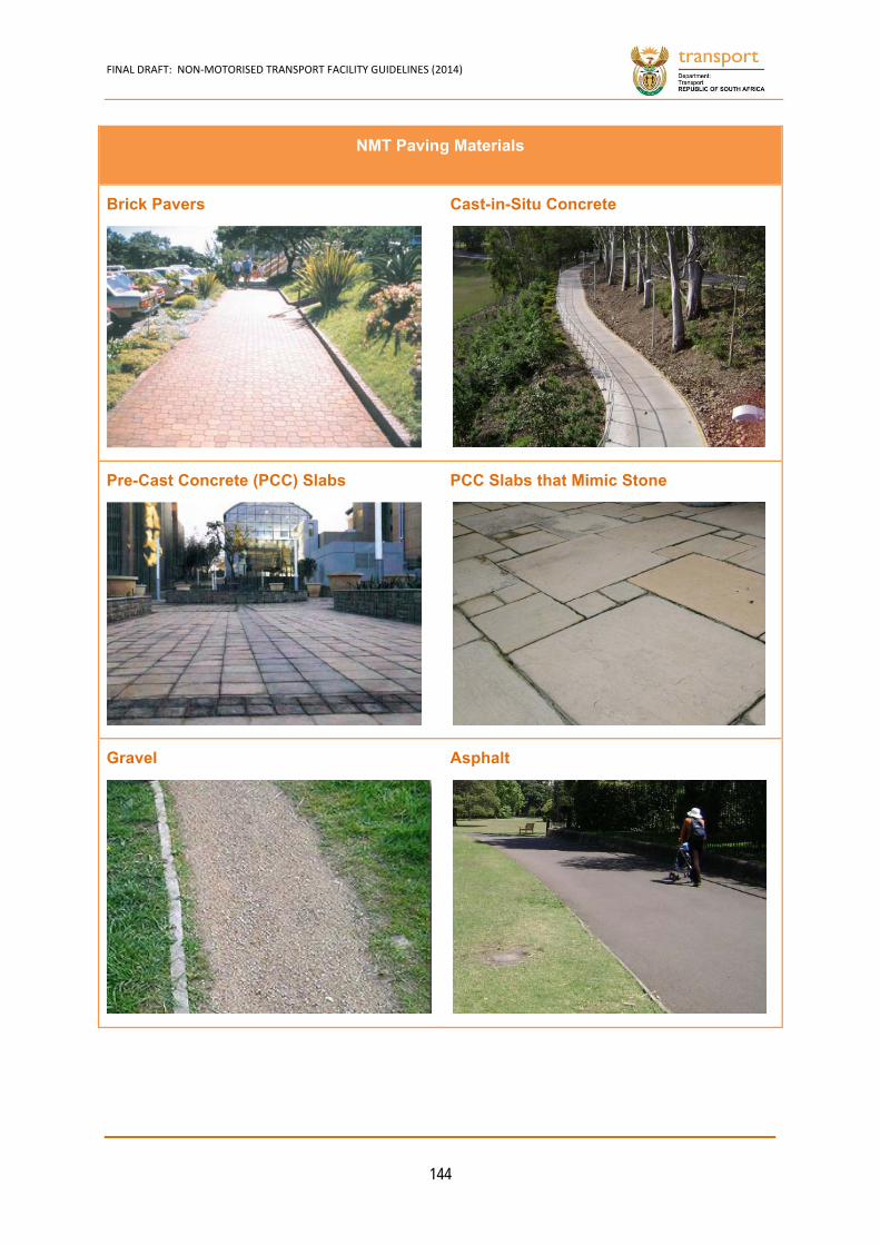
FINAL DRAFT: NON‐MOTORISED TRANSPORT FACILITY GUIDELINES (2014)
144
NMT Paving Materials
Brick Pavers
Cast-in-Situ Concrete
Pre-Cast Concrete (PCC) Slabs
PCC Slabs that Mimic Stone
Gravel
Asphalt

FINAL DRAFT: NON‐MOTORISED TRANSPORT FACILITY GUIDELINES (2014)
145
8.2 Clay and Concrete Brick Pavers
Brick pavers are an appropriate surface for walkways and sidewalks and come in a
variety of colours and strengths. If implemented well with the correct foundations
below the pavers, brick paving creates attractive environments. Laying brick paving
is also more labour intensive than some other surface options. In the long-term,
maintaining good quality brick paving is cheaper than many other materials, as
pavers can be re-laid if deformation of the surfacing takes place or the area needs
to be removed and replaced in order to work on an underground service. Pavers
can also be re-used multiple times.
The Concrete Manufacturers Association (CMA) guidelines should be consulted
when considering brick paving options and specifications.
Substantially bevelled brick pavers are not recommended for bicycle lanes and
pedestrian walkways in view of the roughness and noise levels can cause irritation
if trolleys are used on brick pavers.
8.3 Cobbles and Natural Stone
Natural stone, from large paving slabs to stone cobbles, can be applied in different
ways but are seldom used in South Africa.
8.4 Concrete Slabs
Concrete slabs have been overtaken by concrete bricks in popularity as a form of
paving for walkways. Recently, South Africa has even seen the introduction of
concrete slabs that look like natural stone which can be obtained in various shapes
and sizes.
South African practice uses large concrete paving slabs for the surfacing of NMT
facilities. If installed correctly, good levels
and stability can be achieved.
If the surface becomes uneven, levelling
and maintenance operations are difficult
and it is very difficult to re-use concrete
slabs in the long term. Noise levels on
concrete slabs are less than the levels on
brick, natural stone and concrete paving.
Concrete slabs are comfortable for all NMT
users but must be laid on well-constructed
and stable foundations to minimise deformation.
Cast-in-Situ Concrete Slabs 8.4.1
Cast-in-situ concrete is used extensively for NMT paving. Levels and stability are
easy to achieve if the correct construction practices are used. Adequate
friction/traction is achieved by brooming the surface in the correct manner when
wet. If serious damage occurs, parts of the concrete surface will have to be
Figure 8-1: Deformation atJoints in Concrete Slabs
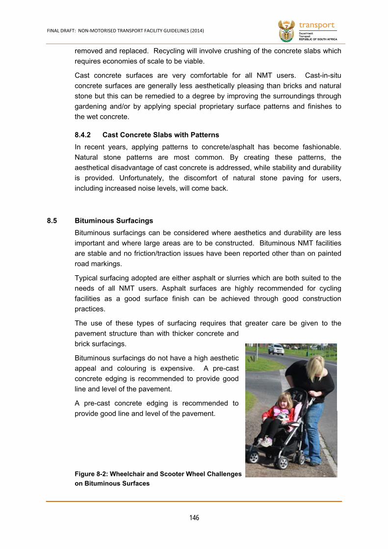
FINAL DRAFT: NON‐MOTORISED TRANSPORT FACILITY GUIDELINES (2014)
146
removed and replaced. Recycling will involve crushing of the concrete slabs which
requires economies of scale to be viable.
Cast concrete surfaces are very comfortable for all NMT users. Cast-in-situ
concrete surfaces are generally less aesthetically pleasing than bricks and natural
stone but this can be remedied to a degree by improving the surroundings through
gardening and/or by applying special proprietary surface patterns and finishes to
the wet concrete.
Cast Concrete Slabs with Patterns 8.4.2
In recent years, applying patterns to concrete/asphalt has become fashionable.
Natural stone patterns are most common. By creating these patterns, the
aesthetical disadvantage of cast concrete is addressed, while stability and durability
is provided. Unfortunately, the discomfort of natural stone paving for users,
including increased noise levels, will come back.
8.5 Bituminous Surfacings
Bituminous surfacings can be considered where aesthetics and durability are less
important and where large areas are to be constructed. Bituminous NMT facilities
are stable and no friction/traction issues have been reported other than on painted
road markings.
Typical surfacing adopted are either asphalt or slurries which are both suited to the
needs of all NMT users. Asphalt surfaces are highly recommended for cycling
facilities as a good surface finish can be achieved through good construction
practices.
The use of these types of surfacing requires that greater care be given to the
pavement structure than with thicker concrete and
brick surfacings.
Bituminous surfacings do not have a high aesthetic
appeal and colouring is expensive. A pre-cast
concrete edging is recommended to provide good
line and level of the pavement.
A pre-cast concrete edging is recommended to
provide good line and level of the pavement.
Figure 8-2: Wheelchair and Scooter Wheel Challenges
on Bituminous Surfaces
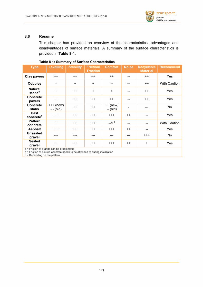
FINAL DRAFT: NON‐MOTORISED TRANSPORT FACILITY GUIDELINES (2014)
147
8.6 Resume
This chapter has provided an overview of the characteristics, advantages and
disadvantages of surface materials. A summary of the surface characteristics is
provided in Table 8-1.
Type Levelling Stability Friction/ Traction
Comfort Noise Recyclable Material
Recommend
Clay pavers ++ ++ ++ ++ -- ++ Yes
Cobbles - + + -- --- ++ With Caution
Natural stonea
+ ++ + + -- ++ Yes
Concrete pavers
++ ++ ++ ++ -- ++ Yes
Concrete slabs
+++ (new) - - (old)
++ ++ ++ (new) -- (old)
- --- No
Cast concreteb
+++ +++ ++ +++ ++ -- Yes
Pattern concrete
+ +++ ++ --/+c -- -- With Caution
Asphalt +++ +++ ++ +++ ++ -- Yes Unsealed
gravel --- --- --- --- --- +++ No
Sealed gravel
++ ++ ++ +++ ++ + Yes
a = Friction of granite can be problematic b = Friction of poured concrete needs to be attended to during installation c = Depending on the pattern
Table 8-1: Summary of Surface Characteristics
CHAPTER 9
FINAL DRAFT: NON‐MOTORISED TRANSPORT FACILITY GUIDELINES (2014)
148
9. MAINTENANCE
“Prevention Is Better Than Cure!”
9.1 Introduction
When construction has been completed the NMT facility enters various operational
stages, including:
Recording of the asset on the asset register as soon as the capital works are completed.
Initial bedding in and defects liability period occurring soon after construction.
Damage and related repairs of underlying pavement layers due to settlement, trees, vegetation, vehicles or heavy equipment.
Preventative maintenance to guard against moisture ingress and moisture accelerated distress.
Terminal condition and rehabilitation.
These stages need to be carefully managed to maximise the life of the facility and
its performance. Monitoring the performance of assets and the related Asset
Management Systems (AMS), as well as project level repair and rehabilitation
assessments, provides the tools to identify and prioritise problems and to attend to
them timeously.
9.2 Management Systems
Asset management systems represent a range of technical tools used to meet the
strategic, tactical and maintenance scheduling needs of the road authority. They
form an important element of the greater asset management framework.
Asset management systems take on a variety of forms, with varying complexity and
are described more fully in TMH22. An essential element of a modern AMS is a
well-integrated database in which to store the road definitions and the related data.
The asset definition dataset sets out how the assets are identified and laid out. It
forms the basis for storing all other data associated with individual assets.
While the management of road pavements and related maintenance practices are
well established, the maintenance of NMT facilities tends to receive less attention.
In addition, most NMT facilities are viewed as components of road assets and
separate condition monitoring and prioritisation is seldom carried out.
This chapter describes the activities and actions that need to be taken by the
parties involved in managing the NMT facilities pavement to ensure longevity and
achievement of the expected performance, or better.
9.3 NMT Inventory
The NMT Inventory and asset register will include the many details for each NMT
asset or component in the system.
All inventories have a hierarchy and in the context of NMT assets as shown below:
FINAL DRAFT: NON‐MOTORISED TRANSPORT FACILITY GUIDELINES (2014)
149
Facility: Complete bicycle lanes, walkways, bus stops, bicycle sheds, etc.
Asset: Individual links or separately identified assets that make up the above
facility such as shelters, etc.
– Components: Individual elements of the asset such as sidewalks, walkways, pedestrian crossings, roofs, area lights, benches, etc.
NMT assets that form part of higher order transport assets such as roads and
bridges are regarded as components of those assets and are linked to them. For
example, a road sidewalk is typically a component of the street and uses the street
name to identify the asset. NMT assets that are part of a separate integrated NMT
facility are regarded as assets and components of that facility and are linked to it.
For example, a bicycle lane from the CBD to a suburb would form a facility with
each link being an asset of that facility.
Other minor NMT components include pedestrian crossings of roadways. These
are generally located at all intersections as well as at other isolated locations
between intersections. It is suggested that this occurs when a separate pedestrian
traffic signal is installed such as where pedestrian volumes are high in CBDs, etc.
The inventory details of NMT facilities can be collected in accordance with the
guidelines provided in the TMH22 Road Asset Management Manual with the
following additional unique attributes.
Sidewalks and NMT facilities are normally classed as components of the associated
road asset and are grouped as such in the TMH22. An NMT facility not linked to
any adjacent road is regarded as a separate asset.
Typical attributes of the NMT asset that should be captured include:
(a) NMT Traffic Category
High volume
Medium Volume
Low Volume
(b) NMT Asset Types
Dedicated NMT walkways and bicycle lanes
Covered walkways
Bicycle racks and sheds
Public transport Interfaces specifically for NMT
Pedestrian and bicycle bridges
Pedestrian and bicycle underpasses.
Traffic calming Infrastructure
Street crossing infrastructure
FINAL DRAFT: NON‐MOTORISED TRANSPORT FACILITY GUIDELINES (2014)
150
Signaling
Parks
Seating and street furniture
Wayfinding or Signage
(c) NMT Component Types
Sidewalk (component of the adjacent street)
Cycle path (component of the adjacent street)
Kerb
Barriers
Gardens
Trees along walkways
The bus stop itself will form part of the public transport assets.
(d) Materials
Slurry Asphalt
Concrete Paving slabs
Bricks /Blocks Gravel
Earth Painted steel
Cast iron
(e) Geometry
Width Length
Thickness Height
Pattern
(f) Standard
High - e.g. paved with edge support as required
Medium - e.g. paved with minimal edge support
Low - e.g. unpaved
Very Low - e.g. earth track
FINAL DRAFT: NON‐MOTORISED TRANSPORT FACILITY GUIDELINES (2014)
151
(g) Separation
The degree of separation between the NMT facility and vehicles is one of the most
important elements of safety of NMT facilities. The six degrees of separation are
defined above in Chapter 4 and include:
i. NMT Only - a separate asset and removed from vehicular traffic over most of its length.
ii. Total - means no conflict will occur between motorised and NMT even in the event of loss of control of the motorised or NMT vehicle. It can be achieved by means of a physical fixed barrier or sufficient separation of >2 to 9 m depending on circumstances.
iii. Partial - means no conflict can occur under normal operating conditions. This is generally achieved by means of a level difference between the travelled ways such as a kerb and sidewalk or by means of temporary barriers.
iv. Marked - on the same surface but separated by means of continuous road markings or a difference in surface texture, such as on a rural road shoulder, for example.
v. Priority - a section of the road where NMT has priority and slow speeds are mandatory but no continuous road markings.
vi. None - NMT competes with motorised vehicles for space on the road.

FINAL DRAFT: NON‐MOTORISED TRANSPORT FACILITY GUIDELINES (2014)
152
9.4 Condition Monitoring
Condition monitoring of the NMT elements should be carried out in a cost-effective
manner. This is often done yearly as an adjunct to the road inspections.
While the TMH9 Pavement Visual Inspection Manual provides guidelines of detailed
inspections of roads, these should not be carried out routinely on NMT facilities.
The distress on these facilities is not traffic-related but more a function of isolated
incidents and occurrences that require occasional rather than routine cyclical
maintenance.
Therefore, the TMH22 generic indicators of condition and functional rating for each
NMT element should be used. In addition, an ambiance rating is included to assess
the attractiveness of the NMT facility. This is shown in Table 9-1.
Rating 1 - Very Good 2 - Good 3 - Fair 4 - Poor 5 - Very Poor
Condition
Rating
Asset is still
like new and
no problems
are expected.
Asset is still in
a condition
that only
requires
routine
maintenance
to retain its
condition.
Some clearly
evident
deterioration
and would
benefit from
preventative
maintenance
or requires
renewal of
isolated areas.
Asset needs
significant
renewal or
rehabilitation
to improve its
structural
integrity.
Asset is in
imminent
danger of
structural
failure and
requires
substantial
renewal or
upgrading.
Functional
Rating
Good service
levels at all
times
Mostly good
service levels
with isolated
problems
occurring at
peak times
Reasonable
service but
with
intermittent
poor service
Generally
poor service
levels with
occasional
very poor
service being
provided.
Very poor
service levels
at most times.
Ambiance
Rating
Very attractive
facility with
visible security
that invites
usage
Isolated
unattractive
elements that
have only little
effect on
potential
usage
Intermittent
unattractive
and unsafe
elements that
should be
improved to
increase
usage
Generally
unattractive
and unsafe
facility that
requires
substantial
improvement
to attract
users
Very
unattractive
and unsafe
facility that
scares away
everyone
except
captured
users
Table 9-1: NMT Asset Condition and Functional Ratings
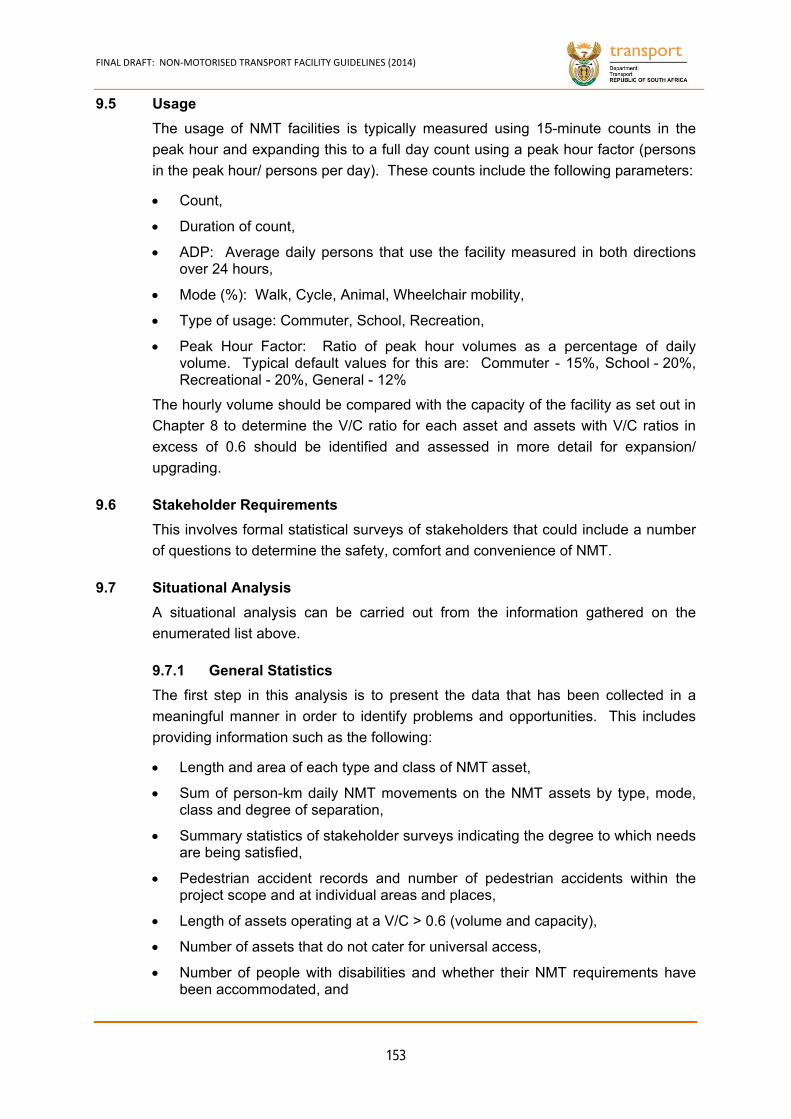
FINAL DRAFT: NON‐MOTORISED TRANSPORT FACILITY GUIDELINES (2014)
153
9.5 Usage
The usage of NMT facilities is typically measured using 15-minute counts in the
peak hour and expanding this to a full day count using a peak hour factor (persons
in the peak hour/ persons per day). These counts include the following parameters:
Count,
Duration of count,
ADP: Average daily persons that use the facility measured in both directions over 24 hours,
Mode (%): Walk, Cycle, Animal, Wheelchair mobility,
Type of usage: Commuter, School, Recreation,
Peak Hour Factor: Ratio of peak hour volumes as a percentage of daily volume. Typical default values for this are: Commuter - 15%, School - 20%, Recreational - 20%, General - 12%
The hourly volume should be compared with the capacity of the facility as set out in
Chapter 8 to determine the V/C ratio for each asset and assets with V/C ratios in
excess of 0.6 should be identified and assessed in more detail for expansion/
upgrading.
9.6 Stakeholder Requirements
This involves formal statistical surveys of stakeholders that could include a number
of questions to determine the safety, comfort and convenience of NMT.
9.7 Situational Analysis
A situational analysis can be carried out from the information gathered on the
enumerated list above.
General Statistics 9.7.1
The first step in this analysis is to present the data that has been collected in a
meaningful manner in order to identify problems and opportunities. This includes
providing information such as the following:
Length and area of each type and class of NMT asset,
Sum of person-km daily NMT movements on the NMT assets by type, mode, class and degree of separation,
Summary statistics of stakeholder surveys indicating the degree to which needs are being satisfied,
Pedestrian accident records and number of pedestrian accidents within the project scope and at individual areas and places,
Length of assets operating at a V/C > 0.6 (volume and capacity),
Number of assets that do not cater for universal access,
Number of people with disabilities and whether their NMT requirements have been accommodated, and
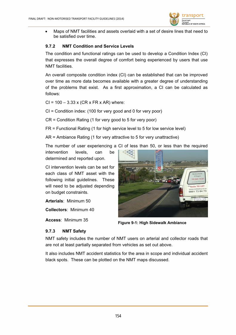
FINAL DRAFT: NON‐MOTORISED TRANSPORT FACILITY GUIDELINES (2014)
154
Maps of NMT facilities and assets overlaid with a set of desire lines that need to be satisfied over time.
NMT Condition and Service Levels 9.7.2
The condition and functional ratings can be used to develop a Condition Index (CI)
that expresses the overall degree of comfort being experienced by users that use
NMT facilities.
An overall composite condition index (CI) can be established that can be improved
over time as more data becomes available with a greater degree of understanding
of the problems that exist. As a first approximation, a CI can be calculated as
follows:
CI = 100 – 3.33 x (CR x FR x AR) where:
CI = Condition index: (100 for very good and 0 for very poor)
CR = Condition Rating (1 for very good to 5 for very poor)
FR = Functional Rating (1 for high service level to 5 for low service level)
AR = Ambiance Rating (1 for very attractive to 5 for very unattractive)
The number of user experiencing a CI of less than 50, or less than the required
intervention levels, can be
determined and reported upon.
CI intervention levels can be set for
each class of NMT asset with the
following initial guidelines. These
will need to be adjusted depending
on budget constraints.
Arterials: Minimum 50
Collectors: Minimum 40
Access: Minimum 35
NMT Safety 9.7.3
NMT safety includes the number of NMT users on arterial and collector roads that
are not at least partially separated from vehicles as set out above.
It also includes NMT accident statistics for the area in scope and individual accident
black spots. These can be plotted on the NMT maps discussed.
Figure 9-1: High Sidewalk Ambiance
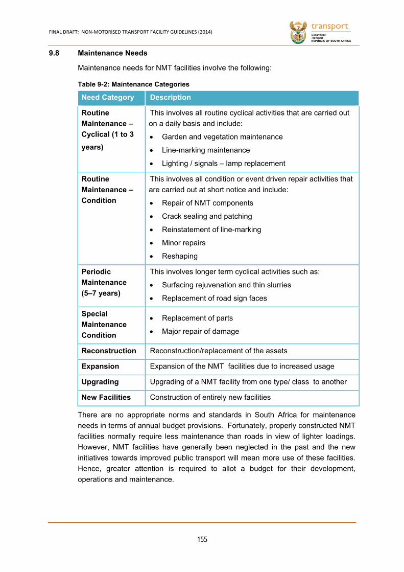
FINAL DRAFT: NON‐MOTORISED TRANSPORT FACILITY GUIDELINES (2014)
155
9.8 Maintenance Needs
Maintenance needs for NMT facilities involve the following:
Need Category Description
Routine
Maintenance –
Cyclical (1 to 3
years)
This involves all routine cyclical activities that are carried out
on a daily basis and include:
Garden and vegetation maintenance
Line-marking maintenance
Lighting / signals – lamp replacement
Routine
Maintenance –
Condition
This involves all condition or event driven repair activities that
are carried out at short notice and include:
Repair of NMT components
Crack sealing and patching
Reinstatement of line-marking
Minor repairs
Reshaping
Periodic
Maintenance
(5–7 years)
This involves longer term cyclical activities such as:
Surfacing rejuvenation and thin slurries
Replacement of road sign faces
Special
Maintenance
Condition
Replacement of parts
Major repair of damage
Reconstruction Reconstruction/replacement of the assets
Expansion Expansion of the NMT facilities due to increased usage
Upgrading Upgrading of a NMT facility from one type/ class to another
New Facilities Construction of entirely new facilities
There are no appropriate norms and standards in South Africa for maintenance
needs in terms of annual budget provisions. Fortunately, properly constructed NMT
facilities normally require less maintenance than roads in view of lighter loadings.
However, NMT facilities have generally been neglected in the past and the new
initiatives towards improved public transport will mean more use of these facilities.
Hence, greater attention is required to allot a budget for their development,
operations and maintenance.
Table 9-2: Maintenance Categories
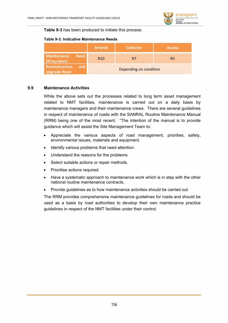
FINAL DRAFT: NON‐MOTORISED TRANSPORT FACILITY GUIDELINES (2014)
156
Table 9-3 has been produced to initiate this process.
Arterial Collector Access
Maintenance Need (R/sq./year)
R10 R7 R5
Reconstruction and Upgrade Need
Depending on condition
9.9 Maintenance Activities
While the above sets out the processes related to long term asset management
related to NMT facilities, maintenance is carried out on a daily basis by
maintenance managers and their maintenance crews. There are several guidelines
in respect of maintenance of roads with the SANRAL Routine Maintenance Manual
(RRM) being one of the most recent. “The intention of the manual is to provide
guidance which will assist the Site Management Team to:
Appreciate the various aspects of road management, priorities, safety, environmental issues, materials and equipment.
Identify various problems that need attention.
Understand the reasons for the problems.
Select suitable actions or repair methods.
Prioritise actions required.
Have a systematic approach to maintenance work which is in step with the other national routine maintenance contracts.
Provide guidelines as to how maintenance activities should be carried out.
The RRM provides comprehensive maintenance guidelines for roads and should be
used as a basis by road authorities to develop their own maintenance practice
guidelines in respect of the NMT facilities under their control.
Table 9-3: Indicative Maintenance Needs
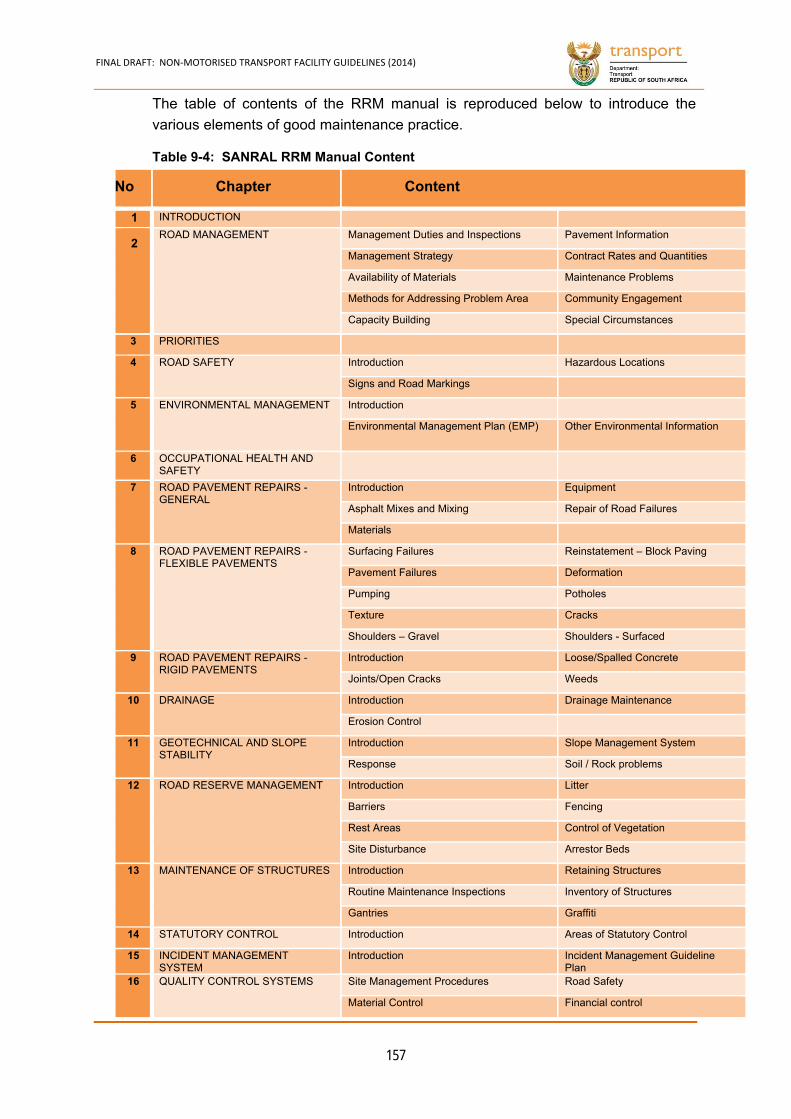
FINAL DRAFT: NON‐MOTORISED TRANSPORT FACILITY GUIDELINES (2014)
157
The table of contents of the RRM manual is reproduced below to introduce the
various elements of good maintenance practice.
No Chapter Content
1 INTRODUCTION
2 ROAD MANAGEMENT Management Duties and Inspections Pavement Information
Management Strategy Contract Rates and Quantities
Availability of Materials Maintenance Problems
Methods for Addressing Problem Area Community Engagement
Capacity Building Special Circumstances
3 PRIORITIES
4 ROAD SAFETY Introduction Hazardous Locations
Signs and Road Markings
5 ENVIRONMENTAL MANAGEMENT Introduction
Environmental Management Plan (EMP) Other Environmental Information
6 OCCUPATIONAL HEALTH AND SAFETY
7 ROAD PAVEMENT REPAIRS - GENERAL
Introduction Equipment
Asphalt Mixes and Mixing Repair of Road Failures
Materials
8 ROAD PAVEMENT REPAIRS - FLEXIBLE PAVEMENTS
Surfacing Failures Reinstatement – Block Paving
Pavement Failures Deformation
Pumping Potholes
Texture Cracks
Shoulders – Gravel Shoulders - Surfaced
9 ROAD PAVEMENT REPAIRS - RIGID PAVEMENTS
Introduction Loose/Spalled Concrete
Joints/Open Cracks Weeds
10 DRAINAGE Introduction Drainage Maintenance
Erosion Control
11 GEOTECHNICAL AND SLOPE STABILITY
Introduction Slope Management System
Response Soil / Rock problems
12 ROAD RESERVE MANAGEMENT Introduction Litter
Barriers Fencing
Rest Areas Control of Vegetation
Site Disturbance Arrestor Beds
13 MAINTENANCE OF STRUCTURES Introduction Retaining Structures
Routine Maintenance Inspections Inventory of Structures
Gantries Graffiti
14 STATUTORY CONTROL Introduction Areas of Statutory Control
15 INCIDENT MANAGEMENT SYSTEM
Introduction Incident Management Guideline Plan
16 QUALITY CONTROL SYSTEMS Site Management Procedures Road Safety
Material Control Financial control
Table 9-4: SANRAL RRM Manual Content
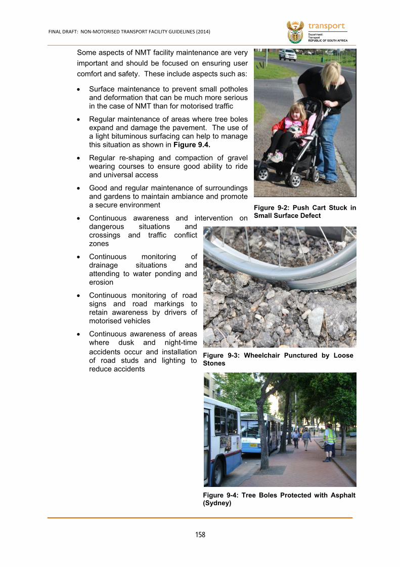
FINAL DRAFT: NON‐MOTORISED TRANSPORT FACILITY GUIDELINES (2014)
158
Some aspects of NMT facility maintenance are very
important and should be focused on ensuring user
comfort and safety. These include aspects such as:
Surface maintenance to prevent small potholes and deformation that can be much more serious in the case of NMT than for motorised traffic
Regular maintenance of areas where tree boles expand and damage the pavement. The use of a light bituminous surfacing can help to manage this situation as shown in Figure 9.4.
Regular re-shaping and compaction of gravel wearing courses to ensure good ability to ride and universal access
Good and regular maintenance of surroundings and gardens to maintain ambiance and promote a secure environment
Continuous awareness and intervention on dangerous situations and crossings and traffic conflict zones
Continuous monitoring of drainage situations and attending to water ponding and erosion
Continuous monitoring of road signs and road markings to retain awareness by drivers of motorised vehicles
Continuous awareness of areas where dusk and night-time accidents occur and installation of road studs and lighting to reduce accidents
Figure 9-2: Push Cart Stuck inSmall Surface Defect
Figure 9-4: Tree Boles Protected with Asphalt(Sydney)
Figure 9-3: Wheelchair Punctured by LooseStones
CHAPTER 10
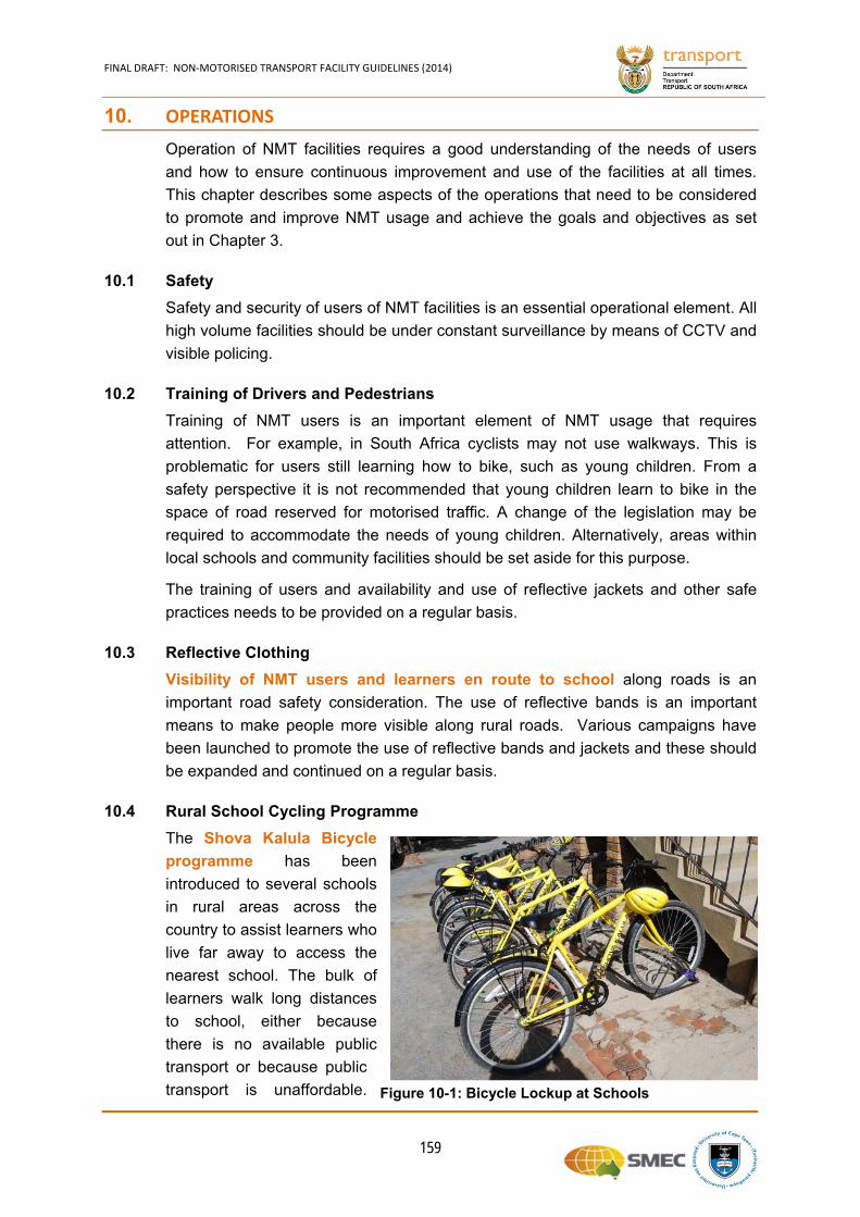
FINAL DRAFT: NON‐MOTORISED TRANSPORT FACILITY GUIDELINES (2014)
159
10. OPERATIONS
Operation of NMT facilities requires a good understanding of the needs of users
and how to ensure continuous improvement and use of the facilities at all times.
This chapter describes some aspects of the operations that need to be considered
to promote and improve NMT usage and achieve the goals and objectives as set
out in Chapter 3.
10.1 Safety
Safety and security of users of NMT facilities is an essential operational element. All
high volume facilities should be under constant surveillance by means of CCTV and
visible policing.
10.2 Training of Drivers and Pedestrians
Training of NMT users is an important element of NMT usage that requires
attention. For example, in South Africa cyclists may not use walkways. This is
problematic for users still learning how to bike, such as young children. From a
safety perspective it is not recommended that young children learn to bike in the
space of road reserved for motorised traffic. A change of the legislation may be
required to accommodate the needs of young children. Alternatively, areas within
local schools and community facilities should be set aside for this purpose.
The training of users and availability and use of reflective jackets and other safe
practices needs to be provided on a regular basis.
10.3 Reflective Clothing
Visibility of NMT users and learners en route to school along roads is an
important road safety consideration. The use of reflective bands is an important
means to make people more visible along rural roads. Various campaigns have
been launched to promote the use of reflective bands and jackets and these should
be expanded and continued on a regular basis.
10.4 Rural School Cycling Programme
The Shova Kalula Bicycle
programme has been
introduced to several schools
in rural areas across the
country to assist learners who
live far away to access the
nearest school. The bulk of
learners walk long distances
to school, either because
there is no available public
transport or because public
transport is unaffordable. Figure 10-1: Bicycle Lockup at Schools
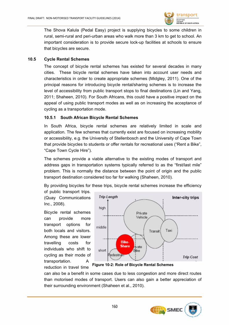
FINAL DRAFT: NON‐MOTORISED TRANSPORT FACILITY GUIDELINES (2014)
160
The Shova Kalula (Pedal Easy) project is supplying bicycles to some children in
rural, semi-rural and peri-urban areas who walk more than 3 km to get to school. An
important consideration is to provide secure lock-up facilities at schools to ensure
that bicycles are secure.
10.5 Cycle Rental Schemes
The concept of bicycle rental schemes has existed for several decades in many
cities. These bicycle rental schemes have taken into account user needs and
characteristics in order to create appropriate schemes (Midgley, 2011). One of the
principal reasons for introducing bicycle rental/sharing schemes is to increase the
level of accessibility from public transport stops to final destinations (Lin and Yang,
2011; Shaheen, 2010). For South Africans, this could have a positive impact on the
appeal of using public transport modes as well as on increasing the acceptance of
cycling as a transportation mode.
South African Bicycle Rental Schemes 10.5.1
In South Africa, bicycle rental schemes are relatively limited in scale and
application. The few schemes that currently exist are focused on increasing mobility
or accessibility, e.g. the University of Stellenbosch and the University of Cape Town
that provide bicycles to students or offer rentals for recreational uses (“Rent a Bike”,
“Cape Town Cycle Hire”).
The schemes provide a viable alternative to the existing modes of transport and
address gaps in transportation systems typically referred to as the “first/last mile”
problem. This is normally the distance between the point of origin and the public
transport destination considered too far for walking (Shaheen, 2010).
By providing bicycles for these trips, bicycle rental schemes increase the efficiency
of public transport trips.
(Quay Communications
Inc., 2008).
Bicycle rental schemes
can provide more
transport options for
both locals and visitors.
Among these are lower
travelling costs for
individuals who shift to
cycling as their mode of
transportation. A
reduction in travel time
can also be a benefit in some cases due to less congestion and more direct routes
than motorised modes of transport. Users can also gain a better appreciation of
their surrounding environment (Shaheen et al., 2010).
Figure 10-2: Role of Bicycle Rental Schemes
FINAL DRAFT: NON‐MOTORISED TRANSPORT FACILITY GUIDELINES (2014)
161
Bicycle rental schemes are also relatively cheaper to implement and operate
compared to alternatives such as shuttle services (Shaheen et al., 2010).
Key Aspects When Implementing a Bicycle Rental Scheme 10.5.2
In order for rental/sharing schemes to be successful, the following aspects should
be carefully considered:
(a) Cycling Infrastructure
There should be sufficient bicycle infrastructure, such as allocated bicycle
lanes/paths in the surrounding areas. This is a key aspect of ensuring that sufficient
volume of users of the bicycle scheme is achieved. Alongside, cycling routes and
lanes there should be adequate and safe parking facilities for the rental bicycles at
key locations that the users may want to park their bicycles at bus stops and other
locations.
(b) Type of Bicycle Rental Scheme Systems
Generally, bicycle rental systems are either manual or automated, depending on
demand, the technology available and the objectives of the bicycle rental scheme.
Manual systems require individuals to rent / collect and return a bicycle to a location
that is supervised and with a staff that run the system on a daily basis. Automated
systems where bicycles are collected and returned with no supervisor rely heavily
on technology and are normally a self-service scheme (Midgley, 2011).
(c) Collection and Drop-Off Points
Public space needs to be available to rental schemes. The collection and drop-off
points need to be appealing, safe and convenient. This would encourage users to
avail of the bicycle rental scheme and ensure the sustainability of the scheme. This
indicates that such schemes could be implemented as a public-private partnership.
(d) Information and Recommended Routes
Recommended routes and areas should be identified for the users. Often users are
novice cyclists, do not know the area well and are unfamiliar with the traffic
conditions. This is especially true for visitors that wish to use the scheme as mode
of transport.
(e) Barriers to Bicycle Rental Schemes
Many of the challenges that face cyclists in general apply also to bicycle rental
schemes. Challenges include safety concerns, limited allocated road space to
cyclists and inclement weather (Cycling in Cities Report, 2007).
In order for bicycle rental schemes to be effective, cyclists need to move through
urban spaces with as few hindrances as possible. Protecting cyclists and making
them feel safe in cities is another important aspect of ensuring that there is
adequate uptake of the bicycle rental scheme.
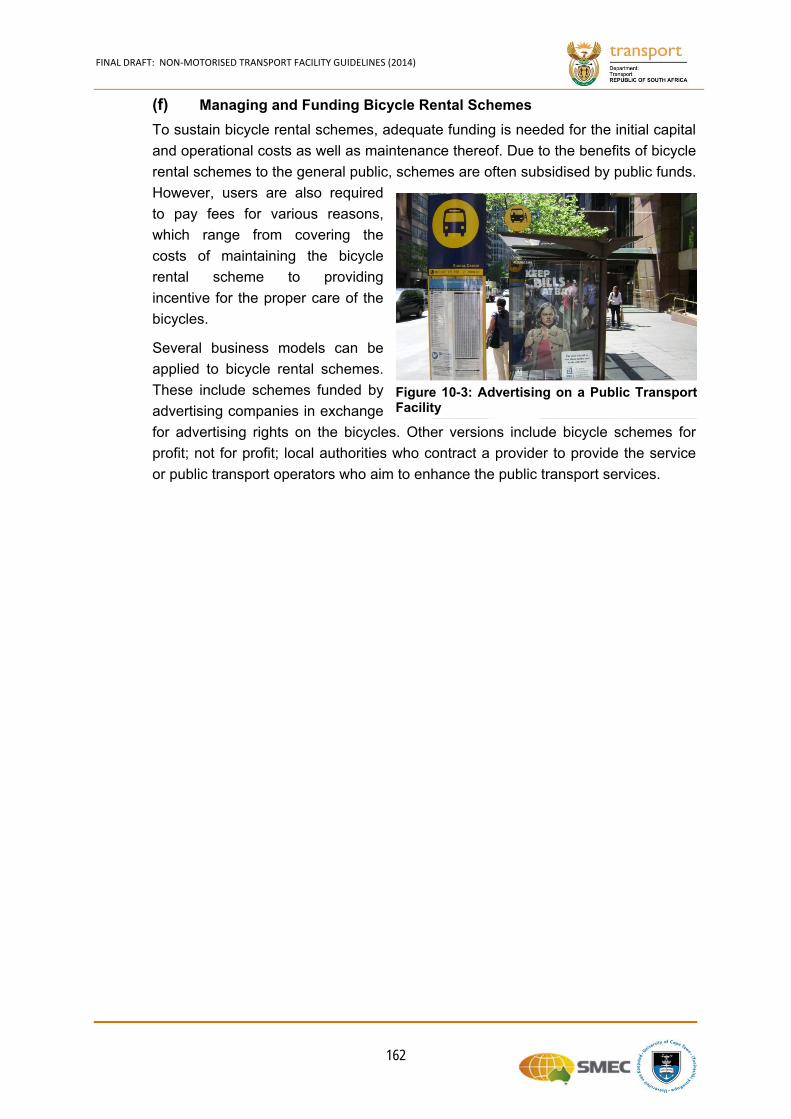
FINAL DRAFT: NON‐MOTORISED TRANSPORT FACILITY GUIDELINES (2014)
162
(f) Managing and Funding Bicycle Rental Schemes
To sustain bicycle rental schemes, adequate funding is needed for the initial capital
and operational costs as well as maintenance thereof. Due to the benefits of bicycle
rental schemes to the general public, schemes are often subsidised by public funds.
However, users are also required
to pay fees for various reasons,
which range from covering the
costs of maintaining the bicycle
rental scheme to providing
incentive for the proper care of the
bicycles.
Several business models can be
applied to bicycle rental schemes.
These include schemes funded by
advertising companies in exchange
for advertising rights on the bicycles. Other versions include bicycle schemes for
profit; not for profit; local authorities who contract a provider to provide the service
or public transport operators who aim to enhance the public transport services.
Figure 10-3: Advertising on a Public TransportFacility


CHAPTER 11
FINAL DRAFT: NON‐MOTORISED TRANSPORT FACILITY GUIDELINES (2014)
163
11. REFERENCES
AASHO, 1964, A Guide for Functional Highway Classification, American
Association of State Highway Officials, National Association of Counties, National
Association of County Engineers, Washington DC.
AUSTROADS. Guide to Traffic Engineering Practice: Part 14—Bicycles. Sydney,
Australia, 1993.
Behrens, R., 2005, Accommodating Walking as a Travel Mode in South African
Cities: Towards Improved Neighbourhood Movement Network Design Practices,
Planning Practice and Research, 20:2, 163-182, DOI:
10.1080/02697450500414686.
Britton, Eric, 2011, World City Bike Forum.
Committee of Transport Officials, 2012, The South African Road Classification and
Access Management Manual, South Africa.
CSIR, 2003, Pedestrian and Bicycle Facility Guidelines: Engineering Manual to Plan
and Design Safe Pedestrian and Bicycle Facilities, Department of Transport, 2003,
South Africa.
De Maio, Paul. 2009, Bike-Sharing: History, Impacts, Models of Provision, and
Future, Journal of Public Transportation, Vol. 12, No. 4.
Department of Transport, 1996, The White Paper on National Transport Policy,
Department of Transport, 1996, Pretoria.
Department of Transport, 2006, The National Land Transport Strategic Framework,
2006, South Africa.
Department of Transport, 2007, The Public Transport Strategy and Action Plan,
2007South Africa.
Department of Transport, 2005, The Rural Transport Strategy for South Africa,
2005, South Africa.
Department of Transport, 2009, The National Land Transport Act 5 of 2009 (NLTA),
South Africa.
Department of Transport, 1996, The National Road Traffic Act 93 of 1996 (NRTA),
South Africa.
Department of Transport, 2000, The National Road Traffic Regulations, 2000, South
Africa.
Department of Transport, 2000, The National Land Transportation Act, 2000 (Act
No. 22 of 2000), South Africa.
Department of Transport (DOT), 2007, Public Transport Strategy: Annexure 1,
2007, South Africa.
FINAL DRAFT: NON‐MOTORISED TRANSPORT FACILITY GUIDELINES (2014)
164
Department of Transport, 2008, Draft of Non-Motorised Transport Policy,
Department of Transport, 2008, South Africa.
Dhingra, Chavvri, 2010, Public Bicycle Schemes: Applying the Concept in
Developing Cities Examples From India.
Federal Transportation Advisory Group (FTAG), 2001, Vision 2050: An Integrated
National Transportation System,
http://www.aeronautics.nasa.gov/docs/FTAG/vision2050.pdf, 2001, United States of
America.
Fishman, E. et al., 2012, Barriers and Facilitators to Public Bicycle Scheme Use: A
Qualitative Approach, Transportation Research Part F, Pages 686–698.
Gadepalli, S. et al., 2011, Toolkit for Public Cycle Sharing Systems, Ministry of
Urban Development Government of India, ITDP, 2011, India.
Gauteng Province: Roads and Transport, 2013, Gauteng 25-Year Integrated
Transport Master, www.itmp25.co.za, South Africa.
Georgia Department of Transport, 2003, Pedestrian and Streetscape Guide, USA
GIBB Consulting Engineers, 2010, Standard Construction Detail and Design
Standards for Intersection Pedestrian Crossing, Pretoria
Hook, Water, 2003, Preserving and Expanding the Role of Non-Motorised
Transport, Sustainable Transport: A Sourcebook for Policy-makers in Developing
Cities, Module 3d, 2003, GTZ, Eschborn, Germany.
I-CE, 2000, The significance of NMT for Developing Countries, Nethelands
Jennings, G., 2011, A Challenge Shared: Is South Africa Ready for a Public Bicycle
System?, 30th Annual Southern African Transport Conference, 2011.
Kopits, E and M. Cropper (2005), Traffic Fatalities and Economic Growth, Accident
Analysis and Prevention, Volume 37, pages 169–178.
Liebermann, S., et al, 2000, Making South Africa Safe: A manual for community
based crime prevention, Pretoria: CSIR Publication BOU/E 2 (2000).
Lin, J and Yang, T., 2011, Strategic Design of Public Bicycle Sharing Systems with
Service Level Constraints, Transportation Research Part E, Pages 284–294.
Rouphail, N, J. Hummer, P. Allen, and J. Milazzo, 1999, Recommended Procedures
for Chapter 13, Pedestrians, of the Highway Capacity Manual, Report FHWA-RD-
98-107, FHWA, U.S. Department of Transportation, 1999, United States of America.
Midgley, P., 2013, The Bike-Share Report, The City Fix
Midgley, P., 2009, The Role of Smart Bike-Sharing Systems in Urban Mobility, Land
Transport Authority, LTA Academy, Journeys: Sharing Urban Transport Solutions,
Issue 2, Singapore
FINAL DRAFT: NON‐MOTORISED TRANSPORT FACILITY GUIDELINES (2014)
165
Midgley, P., 2011, Bicycle-Sharing Schemes: Enhancing Sustainable Mobility in
Urban Areas, (2–13 May 2011), United Nations Department of Economic and Social
Affairs, Commission on Sustainable Development, New York, United States of
America.
New York City, 2009, Bike-Share opportunities in New York City: Commuter
Demand Methodology, 2009, New York.
Pardo, C., 2011, Public Bike Share Information, ITDP, New York.
Peden, M., et al., 2013, Editorials, South African Medical Journal, April 2013, Vol.
103, No. 4
Pucher, J., Dill, J and Handy, S, 2010, Infrastructure, Programs, and Policies to
Increase Bicycling: an International Review, Preventative Medicine 50(1) S106–
S125, United States of America.
Pushkarev, B., and Zupan, Z., 1975, Urban Space for Pedestrians, MIT Press,
Cambridge, Mass., 1975
SABS, 2011, SANS 1025: Animal Drawn Carts, Ed 1, SABS,
http://www.store.sabs.co.za/sans-1025-ed-1-00
SABS, 2011, SANS 1031: Animal Drawn Carts, Ed 1, SABS,
http://www.store.sabs.co.za/sans-1031-ed-1-00
Servaas, M., 2000, The Significance of Non-Motorised Transport for Developing
Countries: Strategies for Policy Development, Interface for Cycling Expertise,
Utrecht, The Netherlands.
Statistics South Africa, 2014, National Household Travel Survey, 2013: Technical
Report, ISBN 978-0-621-42571-0
Statistics South Africa, 2014, National Household Travel Survey: February to March
2013, Statistical release, P0320, South Africa.
National Research Council, 2000, Highway Capacity Manual, Transportation
Research Board, ISBN 0-309-06681-6, Washington, D.C.
Whitelegg, J., 1987, A Geography of Road Traffic Accidents, Transactions Institute
of British Geographers, New Series, Volume 12, Pages 161–176, London, Wiley.
Wittink, R., 2000, The Economic Significance of Cycling: a Study to Illustrate the
Costs and Benefits of Cycling Policy, Habitat Platform, Interface Cycling Expertise,
The Netherlands.
World Health Organization, Status Report on Road Safety in African Countries,
World Health Organization, 2009.
World Health Organization, 2013, Global Status Report on Road Safety 2013:
Supporting a Decade of Action, World Health Organization.
FINAL DRAFT: NON‐MOTORISED TRANSPORT FACILITY GUIDELINES (2014)
166
CROW, 1998, Recommendations for Traffic Provision in Built-Up Areas, ASVV,
CROW Information and Technology Centre for Transport and Infrastructure, Ede,
The Netherlands.