metra blansko converters of electric quantities nmt & mt
47
METRA BLANSKO CONVERTERS OF ELECTRIC QUANTITIES NMT & MT VALUE IS INSIDE SINCE 1911 Since 1911
-
Upload
khangminh22 -
Category
Documents
-
view
3 -
download
0
Transcript of metra blansko converters of electric quantities nmt & mt

METRA BLANSKO CONVERTERS OF
ELECTRIC QUANTITIES NMT & MT
VALUE IS INSIDE
SINCE 1911 Since 1911
2
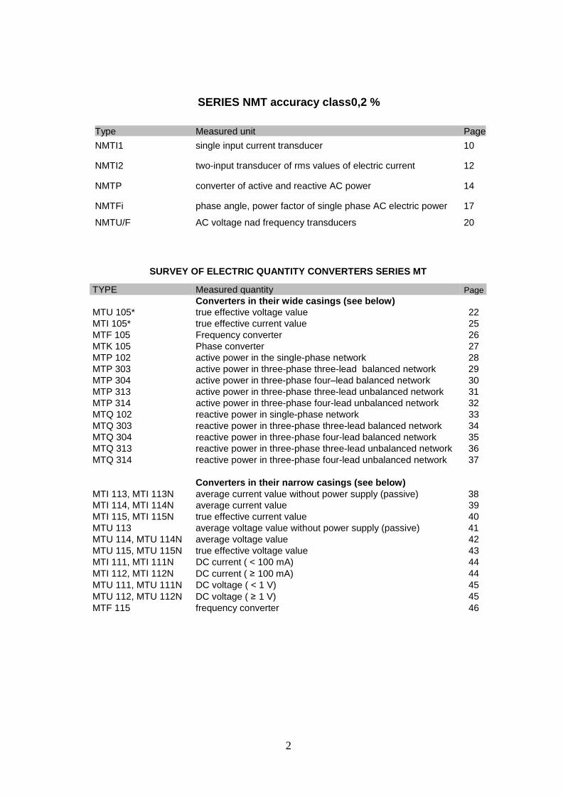
SERIES NMT accuracy class0,2 %
Type Measured unit Page
NMTI1 single input current transducer 10
NMTI2 two-input transducer of rms values of electric current 12
NMTP converter of active and reactive AC power 14
NMTFi phase angle, power factor of single phase AC electric power 17
NMTU/F AC voltage nad frequency transducers 20
SURVEY OF ELECTRIC QUANTITY CONVERTERS SERIES MT
TYPE Measured quantity Page Converters in their wide casings (see below)
MTU 105* true effective voltage value 22
MTI 105* true effective current value 25
MTF 105 Frequency converter 26
MTK 105 Phase converter 27
MTP 102 active power in the single-phase network 28
MTP 303 active power in three-phase three-lead balanced network 29
MTP 304 active power in three-phase four–lead balanced network 30
MTP 313 active power in three-phase three-lead unbalanced network 31
MTP 314 active power in three-phase four-lead unbalanced network 32
MTQ 102 reactive power in single-phase network 33
MTQ 303 reactive power in three-phase three-lead balanced network 34
MTQ 304 reactive power in three-phase four-lead balanced network 35
MTQ 313 reactive power in three-phase three-lead unbalanced network 36
MTQ 314 reactive power in three-phase four-lead unbalanced network 37
Converters in their narrow casings (see below) MTI 113, MTI 113N average current value without power supply (passive) 38
MTI 114, MTI 114N average current value 39
MTI 115, MTI 115N true effective current value 40
MTU 113 average voltage value without power supply (passive) 41
MTU 114, MTU 114N average voltage value 42
MTU 115, MTU 115N true effective voltage value 43
MTI 111, MTI 111N DC current ( < 100 mA) 44
MTI 112, MTI 112N DC current ( ≥ 100 mA) 44
MTU 111, MTU 111N DC voltage ( < 1 V) 45
MTU 112, MTU 112N DC voltage ( ≥ 1 V) 45 MTF 115 frequency converter 46

3
CONVERTERS OF ELECTRIC QUANTITIES MT
The converter series MT represents a generation substitution of original series of converters NC of the same manufacturer.
Application:
The converters are intended for the conversion of electric quantities into the quantity–carrying
DC signal which is either in form of the DC voltage, or the DC forced current. They can be used in
connection with indicating pointer instruments, calibrated in units of the measured quantity, or with
a recorder or, eventually, with a digital instrument. Wide range possibilities are provided by them, also as
sensors for regulation and control purposes in the fields of industrial measurements and, last but not
least, as needful components for acquisition of technological environment picture applied for evaluating
and processing computer systems.
In connection with the built-in comparative board D 5726 (optional upon a customer request), the
measured quantity can be compared in two adjustable levels nearly with all converter types in the wide
casings. The converters are designed for permanent operation and location.
Description:
These converters are designed as independent, built in the plastic casing. In the bottom part of
the basic body the source board is located. The up-to-date source design enables comprising of the
whole range of the power supply voltages, available in two stages, acc. to the customer selection. The
new types of the converters are, if possible, built in their plastic casings of half width. The electronic
circuits are assembled all on one printed circuit board in the SMT assembly. These converters are also
designed in variants without their own sources, with the power supply along the output line.
Each converter comprises the input circuits for the galvanic separation of the proper measuring
circuit and the output amplifier for the output signal conversion to the unified output.
The converter is closed by the plastic lid, creating one integral unit (enabling sealing) with the
basic body. On the lid upper side the label is installed, with data about converter kind and parameters,
including description of clamps and their wiring diagrams. The terminal blocks, enabling connection of 2
leads with their cross-section 0,5 to 4 mm , are located on the opposite sides of the casing. The converter
can be fixed on the rail DIN 46 277 (35 mm). For it, the converter bottom is equipped with the clamping
device. Also the classic way of its fastening on the wall by two screws is possible. The converter terminal
blocks can be (acc. to the order) covered by the cap, which can be sealed. The converter assembly in its
vertical position is recommended (legibility of the label).
Advantages:
- simple assembly on the DIN rail
- high resistance to interfering voltages
- electric strength between the input and output 3700V
- small size and weight
- wide selection of various executions
- optional conversing characteristic
- optional way of power supply
- wide range of working temperatures
- permanent operation
- type attestation, mark CE
- certification for application in NPS
- traditional quality of products brand METRA Blansko

4
VA/V
VA/A
Technical data
These converters are designed in the application group III acc. to the standard ČSN EN 606 88, art 6.1.2.
As for their safety, the converters comply with the standard ČSN EN 61010–1 (acc. to the converter type) Equipment protection class II
Category of over-voltage in installation III (max. working voltage to earth 300Vef)
Category of over-voltage in installation II (max. working voltage to earth 600Vef)
Degree of soiling 2
Auxiliary power supply (optional) 24V, 48V, 60V, 110V ± 20% DC,
120V ± 10% AC (45-65Hz). preferentially: 20 to 120V AC (45 .. 66 Hz), or 20 to 160V DC
100 to 260V AC (45 .. 66 Hz), or 100 to 330V DC
230V ± 15% AC (45-65Hz) power supply along the output line 12 – 36Vss / 30mA (stabilised source, wave < 500mV p-p) Input power (max.) 4W, 7VA (for power supply along the line approx. 0,85W)
Input (optionally) current AC 0...1; 2,5; 5 (A) DC 0…1 mA to 5 A in the sequence 1; 2,5; 5
Voltage AC 0...57,7; 100; 120; 220; 230; 380; 400; 500 (V) DC 0…50 mV to 500 V in the sequence 1; 2,5; 5
(Also other values upon an extra order) The inputs can be connected directly to the measured circuit without the separating transformers (if the input values and the max. voltage network to earth are convenient)
Nominal frequency 50 Hz, 60Hz, (45 - 66 Hz) – it is valid for AC converters of AC quantities
Consumption of inputs (acc. to the converter type) typically
voltage input 1.10-3
current input 3.10-2
Output - (also other values optionally, or upon an extra order) current 0...1; 0...2,5; 0...5; 0...10; 0...20; 4...20 mA voltage 0...1; 0...10 V
conversion characteristic acc. to the converter type (optionally)
Nominal load (acc. to the converter type) voltage output Run = Uan/2mA current output Rin = 6,5V/Ian
Permitted load range
voltage output R u : ∞ to 0,25 R
un
5
current output R : 0 to 2 R i in
Max. output voltage 20V DC
Accuracy class 0,5
Run-in time max. 30 min (typically 5 min. after power supply switch on) Note: After this time the converter fulfils all declared parameters
Time of stabilisation (0/90%) < 200ms (reaction to the unit step of the input signal) Size
70 x 121 x 115 mm
Electric strength (as per ČSN EN 61010-1 )
inputs to the output 3700V, 50Hz/1min output to
the power supply 3700V, 50Hz/1min inputs to the power
supply 3700V, 50Hz/1min clamps to the cover
3700V, 50Hz/1min between inputs 1000 V,
50 Hz/min
Weight acc. to the converter type, max. 700 g
Overload of inputs permanently 120% In, 120% Un
momentarily - 1sec (see Pic.1) 20In, 2Un
Wave on the output max. 0,5 % (peak - peak)
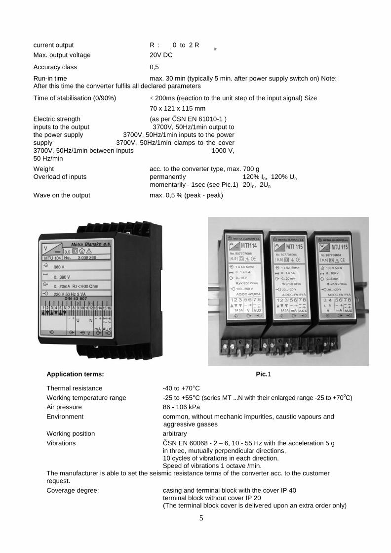
Application terms: Pic.1
Thermal resistance -40 to +70°C
Working temperature range -25 to +55°C (series MT ...N with their enlarged range -25 to +70oC)
Air pressure 86 - 106 kPa
Environment common, without mechanic impurities, caustic vapours and aggressive gasses
Working position arbitrary
Vibrations ČSN EN 60068 - 2 – 6, 10 - 55 Hz with the acceleration 5 g in three, mutually perpendicular directions, 10 cycles of vibrations in each direction. Speed of vibrations 1 octave /min.
The manufacturer is able to set the seismic resistance terms of the converter acc. to the customer request.
Coverage degree: casing and terminal block with the cover IP 40 terminal block without cover IP 20 (The terminal block cover is delivered upon an extra order only)

6
Electro-magnetic compatibility - radiation: as per ČSN EN 500 81 - 2 (industrial environment)
Electro-magnetic compatibility - resistance: as per ČSN EN 6100-6-2 is defined for the individual converter type in their Technical terms
Range of admissible transport temperature: -30 to +60°C.
Converters with power supply 230V 50Hz:
Delivered converters adapted by this way: MTI 111N, MTI 112N, MTU 111N, MTU 112N, MTI 114N, MTI 115N, MTU 114N, MTU 115N. These converters are assembled in thin casings.
These converters have got their power supply source solved by the mains transformer. They are intended for power supply in the network 230V AC only. Their advantage is small interference to the power supply mains and a lower price.
Converters adapted for their power supply along the output line:
Delivered converters adapted by this way: MTI 111, MTI 112, MTU 111, MTU 112, MTI 114, MTI 115, MTU 114, MTU 115, MTF 115. These converters are assembled in thick casings.
These converter have not got their own power supply source, they take the necessary energy for their function from the output line. In the output line the DC source must be inserted, by which the current is forced through the line; the current value is controlled by the converter output circuits in dependence to the measured quantity, by the way given by the converter features. The measurement-carrying quantity is there the current.
Into the output line circuit a scanning resistance can be inserted and the voltage drop on this resistance can be used as the output signal for consequent elaboration.

7
Wiring diagram of the output line – see the picture
Iv - current in the output line Rs - scanning resistance Uv - scanned voltage Uzd - Dc power supply source
(Iv – current in the output line Uv – scanned voltage Rs - scanning resistance Uzd – power supply DC source)
Following is valid:
Rzn = (UZD – 12) / 0,024 [ Ohm ] where the UZD is the line power supply voltage
Rzn is the total line resistance, i.e. resistance of the line lead + scanning (loading) resistance + inner resistance of the power supply source.
Permitted load range - Rz : 0 to Rzn Requirements for
the source:
- galvanic separation acc. to user needs (it is not a term).
Note: The input circuits are always separated from the output by the converter,
- DC voltage UZD = 12V to 36V
- DC current min. 30 mA on one converter
- Wave < 500 mV p-p
Output power > 0,85 W
Storage:
The converters are to be stored in their transport package in wet places at the ambient temperature from +5 to +35°C and the relative humidity up to 75 %. The absolute air humidity must not exceed 15 g/m
and the air must not contain matters causing or supporting rise of corrosion. The converters must be protected against their contingent mechanical damage.
Putting into operation:
At the transport conditions passing to working ones the acclimatisation in the working conditions must be
carried out (with regard to possibility of a moisture condensation), for min. 2 hours.

8
Assembly:
Mechanical assembly: Fixing of the converter on a wall, or inside a case will be carried out by means of
two screws M4. For these screws suitable holes should be drilled in the switchboard, acc. to the sketch.
If located in a closed switchboard the working position is arbitrary, if located in an open switchboard the
vertical position is prescribed. The converter fixing to the assembly rail 35 mm complies with DIN 50 022
– there is a fastening groove on the converter bottom. The upper groove edge should be put on the rail
and by the pressure acting through the converter on the rail the pawl of the fixing device will be locked.
The converter dismantling will be carried out by a screwdriver, by which the pawl can be shifted out up to
the position of the converter releasing from the rail.
Electrical assembly of the instrument: Connection of the converter should be performed acc. to the wiring
diagram belonging to the relevant converter type. Cross-section of the lead connected to the terminal 2
block is 0.5 - 4 mm . Each converter has got a safety fuse in its power supply circuit. As a part of the
converters installation (except the MTI 113, MTU 113 and converters supplied along the output line) the
two-pole switch of the supply voltage and joint protection must be equipped. To provide for an increased
immunity against interferences, the inlet leads should be twisted or, at least, any creation of flat loops
should be prevented.
WARNING: Circuits of the input measured signals, circuits of the auxiliary voltage and circuits of the
output signal are mutually galvanically separated, i.e. the output signal circuit is floating. With regard to
elimination of the interference to the output, we recommend to interconnect all the signal ground lines, if it
is possible, to one point and connect it with the clamp of the functional grounding.
Description of clamps: see Enclosures of individual types of converters.
Constructional dimensions – execution 1 – wide casing Geometry of assembly holes drilling
(two converters side-by-side)
Constructional dimensions – execution 2 – narrow casing Geometry of assembly holes drilling
(two converters side-by-side)
( ↑ assembly holes of further converter)
Assembly holes of next converter

9
Single-input transducer
NMTI 1
The NMTI 1 transducer of alternating current is
intended for mounting into switchboards. Its rated
input current can be arbitrarily adjusted within the
range from 1A to 5A, in accordance with the
requirements of the user. The device measures the
true effective (TRMS) value of AC.
MANUFACTURER:
METRA BLANSKO s.r.o.
Pražská 7, house No. 2536
67801Blansko , Czech Republic
Company reg. No. (IČ): 02356180
Tax reg. No. (DIČ): CZ02356180
Web: www.metra.cz
Warranty and post-warranty repairs, calibrations and
any type of servicing works are carried out
exclusively by the company METRA BLANSKO s.r.o
ENGINEERING PARAMETERS
• powering voltage 20V to 300V DC
20V to 260V AC 50/60 Hz
• power consumption 1.5W at fully loaded outputs
• number of current measuring inputs 1
• rated input current In selectable within 1A to 5A range
• input current range 0 to 1.2 In
• accuracy of current measurement 0.2 % In
• input overload capacity permanently 1.2 In
short-time 20x In /one second
• analogous output 1
-current type 0...20mA;4...20 mA
or on order 0…x mA (x= 5 to 20 mA)
-voltage type 0...10 V
or on order 0…x V (x= 1 to 10 V)
• settling time after the connection of power supply 1 minute
• operating temperature range -25 to +70°C
• permissible load range

10
- voltage output Ru higher than Uan /8mA
- current output Ri loop resistance less than 10V/Ian
• dielectric strength (as per ČSN EN 61010-1)
- inputs against the outputs and power circuits 3700V; 50Hz/1min
- in between the inputs 1000 V; 50 Hz/1min
• weight no more than 150g
• dimensions 101x114x24 mm
• operating temperature range -25 to +70°C
• error caused by ambient temperature
no more than ±0,1%/10°C as per the requirements of ČSN EN 606 88, to apply for –25°C to
+55°C (+ additive error caused by ambient temperature ranging from +55°C to +80°C)
• working position arbitrary
• protection degree IP 20
• electromagnetic compatibility
- radiation: in accordance with ČSN EN 55011-B standard
- immunity: as per ČSN EN 6100-6-2 standard, ed.3
• Safety according to ČSN EN 61010 – 1 standard: equipment of class II, overvoltage
category III after having become a part of the installation (highest voltage against the earth:
300Vrms), pollution degree 2
ORDERING CODE
Parameters of the converter inputs and outputs are defined by a five-digit code number.
The X parameters need to be accurately specified in the purchase order.
Ordering NMTI 1 0 0
Number of current inputs 1
Rated input current
1,0 A 1
2,0 A 2
5,0 A 5
other X
Output
TRMS input current
0…20 mA 1
4…20 mA 2
0…10 V 3
other X
Example of an ordering code:
NMTI 1 2 0 2 0 1 …………………………………………. number of current inputs 1
2 ………………………………….. rated current: 1A
0 ………………............. unused
2 ………………….. output - currend 4…20 mA
0 …………. Unused

11
Two-input transducer of rms values of electric current
NMTI 2
The NMTI 2 is a two-input transducer with two independent analogous outputs. Both of the outputs are
electrically isolated from the outputs, from the power circuits and from each other, so that one NMTI 2
transducer is able to replace two common current transducers. In this way a significant savings of
installation space can be achieved.
ENGINEERING PARAMETERS
• powering voltage 20V to 260V
DC or AC 50/60 Hz
• power consumption 1.5W at fully
loaded outputs
• number of current measuring inputs 2
• rated input current In selectable
within 1A to 5A range
• input current range 0 to 1.2 In
• accuracy of current measurement 0.2 % In
• input overload capacity, permanently 1.2 In
short-time 20 x In /one
second
• analogous outputs 2
- current type 0...20mA; 4...20 mA
or on order 0…x mA (x= 5 to 20 mA)
- voltage type 0...10 V
or on order 0…x V (x= 1 to 10 V)
There is a galvanic interconnection between the GNDA and GNDB ground terminals established
internally in the transducer!
• settling time after the connection of power supply 1 minute
• operating temperature range -25 to +70°C
• error caused by ambient temperature
no more than ±0,1%/10°C, as per the requirements of ČSN EN 606 88 standard, to apply for the
temperature range of –25°C to +55°C (+ 0.2% of additive error caused by ambient temperature ranging
from +55°C to +80°C)
• permitted output load ranges

12
- voltage output Ru higher than Uan /8mA
- current output Ri loop resistance less than 10V/Ian
• dielectric strength (as per ČSN EN 61010-1)
- inputs as against the outputs and power circuits 3700V; 50Hz/1min
- in between the inputs 1000 V; 50 Hz/1min
• weight no more than 150g
• dimensions 101x114x24 mm
• working position arbitrary
• protection degree IP 20
o electromagnetic compatibility radiation: as per ČSN EN 55011-B
▪ immunity: as per ČSN EN 6100-6-2 ed.3
Safety according to ČSN EN 61010 – 1 standard: equipment of class II, overvoltage category III after having
become a part of the installation (highest voltage against the earth: 300Vrms), pollution degree 2
Warranty and post-warranty repairs, calibrations and any type of servicing works are carried out
exclusively by the company METRA BLANSKO s.r.o.
Ordering code Parameters of the converter inputs and outputs are defined by a five-digit code number. The X parameters need to be accurately specified in the purchase order.
Order NMTI ⚫ ⚫ ⚫ ⚫ ⚫
Number of current inputs 2
Rated input current A
1,0 A 1
2,0 A 2
5,0 A 5
Other X
Rated input current B
1,0 A 1
2,0 A 2
5,0 A 5
Other X
Output A TRMS value of input A
0…20 mA 1
4…20 mA 2
0…10 V 3
Other X
Output B TRMS value input B
0…20 mA 1
4…20 mA 2
0…10 V 3
Other X
Example of an ordering code: NMTI 2 2 5 2 3 2 ………………………number of inputs2
2 …………………input A - rated input current 2 A 5 ………….input B - rated input current5 A
2 ……….output A - current 4 … 20 mA 3……output B - voltage 0 … 10 V
13
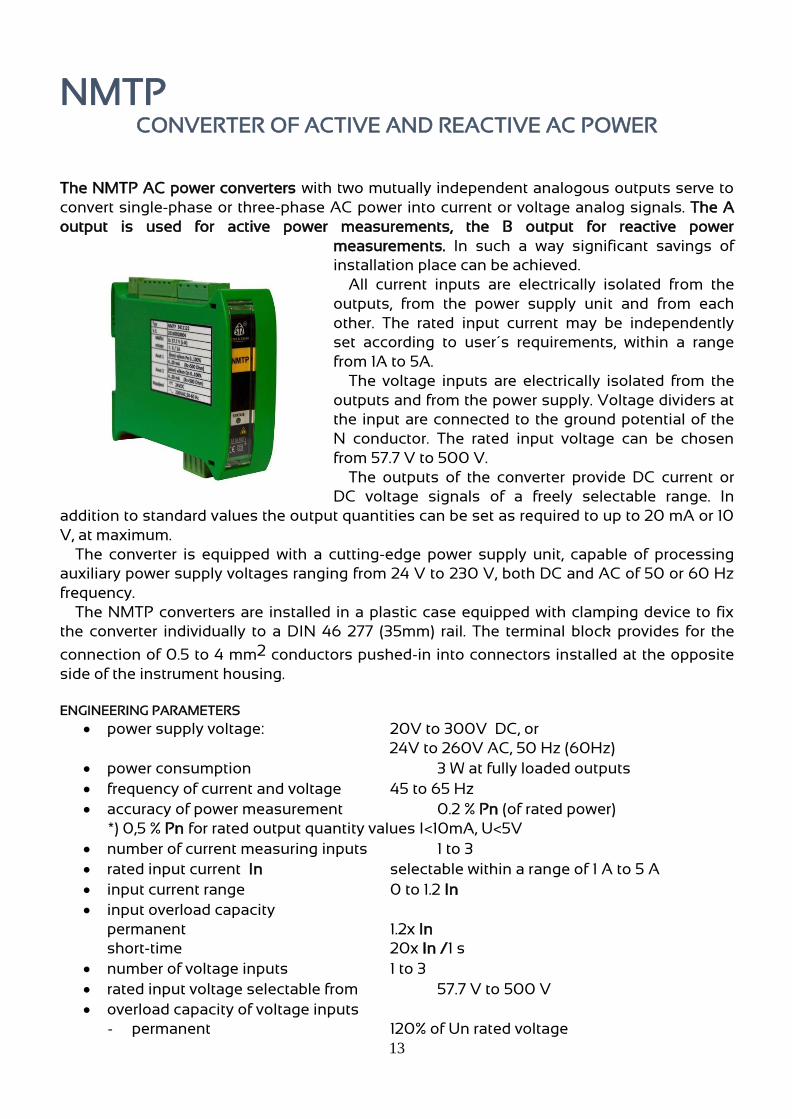
NMTP
CONVERTER OF ACTIVE AND REACTIVE AC POWER
The NMTP AC power converters with two mutually independent analogous outputs serve to
convert single-phase or three-phase AC power into current or voltage analog signals. The A
output is used for active power measurements, the B output for reactive power
measurements. In such a way significant savings of
installation place can be achieved.
All current inputs are electrically isolated from the
outputs, from the power supply unit and from each
other. The rated input current may be independently
set according to user´s requirements, within a range
from 1A to 5A.
The voltage inputs are electrically isolated from the
outputs and from the power supply. Voltage dividers at
the input are connected to the ground potential of the
N conductor. The rated input voltage can be chosen
from 57.7 V to 500 V.
The outputs of the converter provide DC current or
DC voltage signals of a freely selectable range. In
addition to standard values the output quantities can be set as required to up to 20 mA or 10
V, at maximum.
The converter is equipped with a cutting-edge power supply unit, capable of processing
auxiliary power supply voltages ranging from 24 V to 230 V, both DC and AC of 50 or 60 Hz
frequency.
The NMTP converters are installed in a plastic case equipped with clamping device to fix
the converter individually to a DIN 46 277 (35mm) rail. The terminal block provides for the
connection of 0.5 to 4 mm2 conductors pushed-in into connectors installed at the opposite
side of the instrument housing.
ENGINEERING PARAMETERS
• power supply voltage: 20V to 300V DC, or
24V to 260V AC, 50 Hz (60Hz)
• power consumption 3 W at fully loaded outputs
• frequency of current and voltage 45 to 65 Hz
• accuracy of power measurement 0.2 % Pn (of rated power)
*) 0,5 % Pn for rated output quantity values I<10mA, U<5V
• number of current measuring inputs 1 to 3
• rated input current In selectable within a range of 1 A to 5 A
• input current range 0 to 1.2 In
• input overload capacity
permanent 1.2x In
short-time 20x In /1 s
• number of voltage inputs 1 to 3
• rated input voltage selectable from 57.7 V to 500 V
• overload capacity of voltage inputs
- permanent 120% of Un rated voltage

14
- short-time 200% of Un during 1 second
• analogous outputs 2
- current outputs 0...20mA; 4...20 mA; -20...0...+20mA
or on order 0…x mA (x= 5 to 20 mA)
- voltage outputs 0...10 V
or on order 0…x V (x= 1 to 10 V)
• rated burden at the output
- voltage output Run = Uan / 2mA
- current output Rin = 5 V/ Ian
(Ian = rated output current)
• permissible load range
- voltage output Ru higher than 0.25 Run
- current output resistance Ri of the loop less than 2xRin
• highest output voltage ±13V DC
• settling time of the output [0/90%] 100ms (response time to unit-pulse signal 0 -> 100% of rated input value)
• settling time after power supply connection: 1 minute
• dielectric strength (acc. to ČSN EN 61010-1 )
- inputs to outputs 3700V, 50Hz/1min - inputs to power supply 3700V, 50Hz/1min - inputs to auxiliary power supply 3700V, 50Hz/1min - terminals to the case 3700V, 50Hz/1min - between the inputs 1000 V, 50 Hz/min
• material of the case PC/ABS
• weight max. 200 g
• dimensions 101x114x35 mm • operating temperature range -25 to +70°C
• error caused by ambient temperature max. ±0.1%/10°C to ČSN EN 606 88, within the range of –25°C to +55°C (+ auxiliary error caused by ambient temperature of 0.2% within +55°C to +80°C)
• operating position any desired
• protection degree IP 20 • electromagnetic compatibility emission: acc. to ČSN EN 55011-B
immunity to industrial environments: acc. to ČSN EN 6100-6-2, ed.3 Safety in accordance with ČSN EN 61010 – 1 standard; usage group (protection class) II, appliance class (overvoltage category) III (highest operating voltage to earth: 300Vrms), pollution degree 2
Types of converters depending on the mains in which the measurement is taking place
NMTP 11x power converter installed in a single-phase power mains
NMTP 13x power converter installed in a three-phase, three-conductor, balanced power mains
NMTP 14x power converter installed in a three-phase, four-conductor, balanced power mains
NMTP 23x power converter installed in a three-phase, three- conductor, unbalanced power mains
NMTP 34x power converter installed in a three-phase, four-conductor, unbalanced power mains

15
ORDERING CODE
Parameters of the converter inputs and outputs are defined by a seven-digit code number. The X parameters need to be accurately specified in the purchase order.
Ordering NMTP ⚫ ⚫ ⚫ ⚫ ⚫ ⚫ ⚫
No. of current inputs
1 1
2 (Aron) 2
3 3
single-phase mains
1
three-phase mains
3 conductors 3
4 conductors 4
Rated input current [ A ]
1,0 1
2 2
5 5
other value X
Rated input voltage [ V ]
100/ √3 1
110/ √3 2
100 3
110 4
230 5
400 6
other value X
Measuring range [% Pn]
0…+120 1
-120…+120 2
-100…+120 3
other value X
Output A active power
0…20 mA 1
4…20 mA 2
-20...0...+20mA 3
0…10 V 4
other value X
Output B reactive power
0…20 mA 1
4…20 mA 2
-20...0...+20mA 3
0…10 V 4
other value X
Parameters of inputs Outputs
Example of an ordering code: NMTP 3 4 1 3 3 2 2
3 ………………………………. number of current inputs:3 4……………………………. number of voltage terminals: 4 1…………………………rated current: 1A 3……………………rated phase-to-phase voltage of 100 V
3………………measuring range -100% to +120% Pn 2…………output A 4…12…20 mA 2…..output B 4…12…20 mA

16
PHASE ANGLE AND POWER FACTOR TRANSDUCER OF SINGLE-PHASE AC ELECTRIC POWER
NMTFi
The NMTFi device is a phase angle and power factor transducer operated in single-phase power network and featuring two independent analogous outputs. The A output measures the phase angle between voltage and current, the B output measures the power factor. In such a was one single NMFTi transducer is able to replace two customary transducers thus making it possible to achieve significant savings in installation space.
The current input is electrically isolated from the outputs and from the power source. The rated input current can be set as required within a range of 1 A to 5A. The voltage input is electrically isolated from the outputs and the power source. The rated input voltage can be chosen within a range of 57.7 V to 500 V.
Output of the transducer is DC current or DC voltage of a value the range of which can be selected. On request the range of output quantity may be optionally limited to a maximum level of 20 mA or 10 V.
The transducer incorporates an advanced power source capable to process auxiliary power supply AC voltages
from 24 V to 230 V, within frequency range from 50 Hz to 60 Hz, or DC voltages ranging from 20 V to 300 V. The NMTFi transducers are installed in a plastic case with clamping fixture for mounting on DIN 35 mm rail (DIN 46 277). The terminal blocks to which conductors
of 0.5 to 4 mm2 may be connected, are plugged-in into connectors situated at the opposite side of the case.
ENGINEERING PARAMETERS
• power supply voltage 20V to 300V DC or 24V to 260VAC/50 Hz (60Hz)
• power consumption 3 VA at full load at the outputs • number of voltage inputs 1
• rated input voltage selectable within 57.7V to 500 V
• overload capacity of voltage input 120% of Un rated voltage, constant operation
200% of Un, for short time (1s) • number of current inputs 1
• rated input current In selectable within 1 A to 5 A
• input current range 0 to 1.2 of In (rated current)
• overload capacity of current input 1.2x In; 20x In during a short time (1s)
• phase angle measuring ranges ± 60°; ± 90°; ± 120°
• phase angle measuring accuracy ±0.02°
• power factor measuring range (cos φ) 0.5 cap ... 1 ... 0.5 ind
• power factor measuring accuracy ±0.002
• analogous outputs 2
17
current outputs 0...20mA; 4...20 mA , or 0…x mA (x= 5 mA to 20 mA) voltage outputs 0...10 V or 0…x V (x= 1 V to 10 V)
• rated load of the output voltage output Run = Uan / 2mA current output Rin = 5 V/ Ian (Ian = rated output current)
• permitted output load range voltage output Ru > than 0.25 Run current output loop resistance Ri of less than 2xRin
• settling time after connecting the power supply 1 minute
• dielectric strength (to ČSN EN 61010-1 standard) between inputs and outputs, between inputs and the power source, between inputs and the auxiliary power source, terminals against the cover 3700V, 50Hz/1min between the inputs 1000 V, 50 Hz/min
• material of the case PC/ABS
• weight max. 200g
• dimensions 101x114x35 mm
• operating temperature range -25° C to +70°C
• operating position any desired
• protection degree IP 20
• electromagnetic compatibility radiation: in accordance with ČSN EN 55011-B standard immunity: in acc. with ČSN EN 6100-6-2, ed.3 standard
• safety corresponding to ČSN EN 61010 – 1 standard: equipment of the protection class II, overvoltage category III in the installation (highest voltage of 300Vrms against the earth), pollution degree 2

18
Order code
The parameters of the input and output are defined by a six-digit code. It is essential to accurately specify the X parameters in the purchase order.
Ordering NMTFi * * * * * *
Rated input voltage [ V ]
100/ √3 1
110/ √3 2
100 3
110 4
230 5
400 6
other value X
Rated input current [ A ]
1,0 1
2 2
5 5
other X
Phase angle measuring range
± 60° 1
± 90° 2
± 120° 3
other value X
Power factor measuring range
0.5 cap. ... 1 ... 0.5 ind. 1
other value X
Output A phase angle
0…10…20 mA 1
4 …12…20 mA 2
0… 5 …10 V 3
other value X
Output B power factor
0…10…20 mA 1
4 …12…20 mA 2
0… 5 …10 V 3
other value X

19
AC VOLTAGE AND FREQUENCY TRANSDUCERS
NMTU/F
The NMTU/F device is an AC voltage and frequency transducer with two independent analogous outputs. The A output measures AC voltage, the B output measures the frequency of input voltage. That´s why one single NMTU/F transducer is able to replace two customary transducers, thus making it possible to achieve significant savings in installation space.
The voltage inputs are electrically isolated from the outputs and from the power source. Voltage dividers at the input are connected to voltage potential equal to that of the zero (N) conductor. The rated input voltage can be chosen within a range of 57.7 to 500 V.
Output of the transducer is DC current or DC voltage of a value the range of which can be selected. In addition to the default values the output quantity may optionally be chosen to up to 20 mA or 10 V.
The transducer incorporates an advanced power source capable to process auxiliary power supply AC voltages from 24 V to 230 V, within frequency range from 50 Hz to 60 Hz, or DC voltages ranging from 20 V to 300 V. The NMTU/F transducers
are installed in a plastic case with clamping fixture for mounting on DIN 35 mm rail (DIN
46 277). The terminal blocks to which conductors of 0.5 to 4 mm2 may be connected, are plugged-in into connectors situated at the opposite side of the case.
ENGINEERING PARAMETERS
• power supply voltage 20V to 300V DC or 24V to 260VAC/50 Hz (60Hz)
• power consumption 3 VA at full load at the outputs
• frequency of the measured voltage 45 to 65 Hz • accuracy of frequency measurement ± 0.025 Hz
± 0.05 Hz for output quantity rated values of I<10mA, U<5V
• accuracy of voltage measurement ± 0.2 % Un (rated voltage) ± 0.5 % Un for output quantity rated values of I<10mA, U<5V
• number of voltage measuring inputs 1
• rated input voltage selectable within 57.7V to 500 V
• overload capacity of voltage inputs constant operation 120% of rated Un voltage short-time 200% Un during 1 s
• number of analogous outputs 2 current outputs 0...20mA; 4...20 mA, or 0…x mA (x= 5 mA to 20 mA) voltage outputs 0...10 V or 0…x V (x= 1V to 10 V)
• rated load at the output voltage output Run = Uan / 2mA current output Rin = 5 V/ Ian (Ian = rated output current)
• permitted output load range voltage output Ru > than 0.25 Run

20
current output Ri loop resistance < than 2xRin
• highest output voltage ±18V DC
• settling time after connecting the power supply 1 minute
• dielectric strength (to ČSN EN 61010-1 standard) between inputs and outputs, between inputs and the power source, between inputs
and the auxiliary power source, terminals against the cover 3700V, 50Hz/1min between the inputs 1000 V, 50 Hz/min
• material of the case PC/ABS
• weight max. 200g
• dimensions 101x114x35 mm
• operating temperature range -25° C to +70°C
• operating position any desired
• protection degree IP 20
• electromagnetic compatibility radiation: in accordance with ČSN EN 55011-B standard immunity: in acc. with ČSN EN 6100-6-2, ed.3 standard
• safety corresponding to ČSN EN 61010 – 1 standard: equipment of the protection class II, overvoltage category III in the installation (highest voltage of 300Vrms against the earth), pollution degree 2
Order code The parameters of the input and output are defined by a four-digit code. It is essential to accurately specify the X parameters in the purchase order.
Example of an order code:
NMTU/F 3 2 2 1 3………………….… rated input voltage of 100 V 2 ……………… frequency measuring range 45…50…55Hz
2 ………… output A 4…12…20 mA 1 …… output B 0…10…20 mA
Ordering NMTU/F * * * *
Rated input voltage [V]
100/ √3 1
110/ √3 2
100 3
110 4
230 5
400 6
other value X
Frequency measuring range [Hz]
48…50…52 Hz 1
45…50…55 Hz 2
58…60…62 Hz 3
55…60…65 Hz 4
other value X
Output A voltage
0…20 mA 1
4…20 mA 2
0…10 V 3
other value X
Output B voltage frequency
0…20 mA 1
4…20 mA 2
0…10 V 3
other value X

Type: MTU 105 - Converter of the true effective voltage value
21
Conversion characteristics:
The conversion characteristics are a graphic expression of the transmission function: A = f (E), where
A is an output quantity (measure-carrying current of the current loop, or voltage)
E is an input quantity (e.g. measured current, voltage, frequency, or power, etc.)
The converter series MT uses 6 following conversional characteristics:
Characteristic: No. 1 measurement of the input quantity in one direction
No. 2 measurement of the input quantity interval (so called magnifying glass)
No. 3 measurement of the input quantity in the both directions
No. 4 measurement of the input quantity with the suppressed beginning
No. 5 measurement of the input quantity with an overload
No. 6 measurement of the input quantity in the both directions with one polarity output
Specific information to the individual types of the converters are given in following enclosures.
Graphic expression of conversional characteristics: Note.: the index "n" means the value of the nominal quantity
1 2
3 6
Upon an agreement with the manufacturer, the characteristics No.4 and No.5 can be produced for the converters MTI 104 and MTI 105.
4 5

Type: MTU 105 - Converter of the true effective voltage value
22
Ordering: Complete features of converters are defined by their types and 6-digit codes.
The type indicates the measured quantity (see the individual types of the converters) The 6-digit code indicates: 1
st digit the input voltage (0 at the current converter)
2nd
digit the input current (0 at the voltage converter)
3rd
digit the measuring range (typically 1, .i.e. 0 to 120%)
4th
digit the conversion characteristic (typically 1)
5th
digit the output quantity
6th
digit the auxiliary power supply The basic data about the converter are specified on its label
By its own selection, the customer will create the 6-digit number (code) acc. to the tables (see below) by which his requirement for the converter execution is specified. Required parameters can be also put down verbally. If more, or different parameters are required, it must be agreed with the manufacturer separately. If the technical possibilities enable such solution, the customer request can be fulfilled by the form of an extra order.
Following must be specified in your orders:
- instrument name, including its 6-digit code, specifying the execution (or verbal description of all required parameters) – see the individual types of the converters
- number of pc - delivery term - delivery destination, in an extra cases also the way of transport
- way of the package, if any special packing is required for export - any non-standard execution must be settled with the manufacturer in advance - bank connection and way of payment

Type: MTU 105 - Converter of the true effective voltage value
23
Description of function: The input signal is galvanically separated by the transformer, then it is processed by the circuit for the analogical calculation of the effective value. The resulting DC signal is filtered and magnified to the unified output signal. This converter type can be used for the voltage measurements in all circuits, i.e. also in places, where a voltage distortion by the higher harmonic frequencies occurs (e.g. rectifiers, frequency converters, circuits with the phase control etc.). This type can be replaced by the innovated type MTU 115.
Terms of application: Measured voltage range 0 ÷ 120% Un, or so-called volt-lens acc. to the order Description of clamps: wide casing 9,12 input of the measured voltage
13,14 output signal (14 +) 15,16 auxiliary power supply AC, DC (16 +) 1,2,3,4,5,6,7,8,10,11 - unwired
Input consumption 5.10-4 VA/V
Conversion characteristic type No.1, measurement of the input quantity in one direction No.2, measurement of the input quantity interval (so-called volt-lens)
Wiring diagram of the converter:
Power supply Output
Legend: To the converter clamps No. 9, 12 the voltage measuring transformer output will be connected, or the measured voltage directly (acc. to the converter range and the scanned voltage value); to the converter clamps No. 13, 14 (converter output) the evaluation device will be connected; to the clamps No. 15, 16 (auxiliary power supply) the power supply voltage will be connected acc. to the converter data label (acc. to the customer selection, specified in his order)
Formation of the 6-digit code:
Data for orders: MTU 105 . 0 . . . .
Input – nominal voltage Un (V)
100/√3 1 100 2 120 3 220 4 380 5 500 6 230 7 400 8
Measuring range (E)
0 ... 1,2 1 1 0,8 ... 1,2 2 2
0,85 ... 1,15 3 2 0,9 ... 1,1 4 2
Output – nominal value
1 mA 1 2,5 mA 2
5 mA 3 10 mA 4 20 mA 5
4 ... 0 mA 6 1 V 7 10 V 8
Auxiliary power supply
20 to 120V AC (45 to 66 Hz), 20 to 160V DC 7 100 to 260V AC (45 to 66 Hz), 100 to 330V DC 8

24
Type: MTI 105 Converter of true effective current value
Description of function: The input signal is galvanically separated by the transformer, then it is processed by the circuit for the analogical calculation of the effective value. The resulting DC signal is filtered and magnified to the unified output signal. This converter type can be used for the current measurements in all circuits, i.e. also in places, where a current distortion by the higher harmonic frequencies occurs (e.g. rectifiers, frequency converters, circuits with the phase control etc.). This converter type can be replaced (except the characteristics 4 and 5) by the innovated type MTI 115.
Terms of application Measuring range 0% to 120% In, 0% to 100% In for the characteristic No.4 Description of clamps: wide casing 1,2 input of the measured current
13,14 output signal (14 +) 15,16 auxiliary power supply AC, DC (16 +) 3,4,5,6,7,8,9,10,11,12 - unwired
Input consumption 3.10-2 VA/A Conversion characteristic type (arbitrary) - No.1, No.4, No.5
No.1 measurement of the input quantity in one direction No.4 measurement of the input quantity with its suppressed beginning No.5 measurement of the input quantity with its suppressed end (overload)
Wiring diagram of the converter:
Power supply Output
Formation of the 6-digit code:
Data for orders: MTI 105 0 . . . . . Input – nominal current In (A)
1 1 2,5 2 5 3
Measuring range (E)
0 ... 1,2 1 1 0 ... 1,2 1 5 0 ... 1 2 4
Output – nominal value
1 mA 1 2,5 mA 2
5 mA 3 10 mA 4 20 mA 5
4…20 mA 6 1 V 7 10 V 8
Auxiliary power supply
20 to 120V AC (45 .. 66 Hz), or 20 to 160V DC 7 100 to 260V AC (45 .. 66 Hz), or 100 to 330V DC 8

25
Type: MTF 105 – Frequency converter
Description of function: The input voltage signal is separated galvanically by the optic element. After its shaping by the comparator it can be used for starting of the mono-stable toggle circuit. The measurement stability is derived from the quartz-controlled oscillator. The output signal from the mono-stable circuit is filtered and magnified to the unified output signal. Owing to the functional principle the output signal fluctuates, in dependence on the measured frequency, within the limits of the instrument accuracy class.
Terms of application: Measuring range (E) 48.... 52 Hz, 45.... 55 Hz, 58.... 62 Hz, 55.... 65 Hz Input signal range 80% to 120% Un
Input consumption 2.10-3 VA/V Description of clamps: wide casing 9,12 input of the measured voltage signal
13,14 output signal (14 +) 15,16 auxiliary power supply AC, DC (16 +) 1,2,3,4,5,6,7,8,10,11 - unwired
Accuracy class 0,1 Hz Conversion characteristic type: No.2 Wiring diagram of the converter:
Power supply Output
Formation of the 6-digit code:
Data for orders: MTF 105 . 0 . 2 . .
Input - nominal voltage Un (V)
100/√3 1 100 2 120 3 220 4 380 5 500 6 230 7 400 8
Measuring range (E)
48…52 Hz 1 2 45…55 Hz 2 2 58…62 Hz 3 2 55…65 Hz 4 2
Output – nominal value
1 mA 1 2,5 mA 2
5 mA 3 10 mA 4 20 mA 5
4 .. 20 mA 6 1 V 7
10 V 8 Auxiliary power supply
20 to 120V AC (45..66 Hz), or 20 to 160V DC 7 100 to 260V AC (45..66 Hz), or 100 to 330V DC 8

Type: MTK 105 - Phase converter
26
Description of function: The input signals are separated galvanically by transformers. After their shaping by comparators they control toggling of the RS toggle circuit. The RS output voltage is filtered and magnified to the unified output signal. This converter is intended for the measurement of the phase angle between the voltage and the current, or between two voltages. The phase angle is measured during the signal passing through the zero.
Terms of application Measuring range ± 60°, ± 90°, ± 120°
Input voltage range 50 to 120% of the voltage nominal value Input current range 10 to 120% of the current nominal value Description of clamps: wide casing 1,2 input of the measured current, 9,12 input of the measured voltage
alternatively 9,10 input of the first voltage 1,12 input of the second voltage
13,14 output signal (14 +) 15,16 auxiliary power supply AC, DC (16 +)
3,4,5,6,7,8,10,11 - unwired
Input consumption 5.10-4 VA/V, 3.10-2 VA/A Conversion characteristic type No.6 Wiring diagram of the converter:
MTK 105 (voltage, current) MTK 105 (voltage, voltage)
Formation of the 6-digit code:
Power supply Output Power supply Output
Data for orders: MTK 105 . . . 6 . .
Input one – nominal voltage Un (V)
100/√3 1 100 2 120 3 230 4 400 5 500 6
Input two – nominal current In (A)
1 1 2,5 2 5 3
Input two – nominal voltage Un (V)
100/√3 4 100 5 120 6 230 7 400 8 500 9
Measuring range (E)
±60° 1 6 ±90° 2 6
±120° 3 6
Output – nominal value
1 mA 1 2,5 mA 2
5 mA 3 10 mA 4 20 mA 5
4 ... 20 mA 6 1 V 7 10 V 8
Auxiliary power supply
20 to 120V AC (45..66 Hz), or 20 to 160V DC 7 100 to 260V AC (45..66 Hz), or 100 to 330V DC 8

Type: MTP 102 - Converter of the active power in the single-phase network
27
Description of function: The input signals are galvanically separated by transformers and magnified. After multiplication by the TDM modulation principle the resulting DC signal is filtered and magnified to the unified output signal. The converter is of the single-system type.
Terms of application Measuring current range 0% to 120% In. Measured voltage range 50% to 120% Un. Description of clamps: wide casing 1,2 input of the measured current
9,12 input of the measured voltage 13,14 output signal (14 +) 15,16 auxiliary power supply AC, DC (16 +) 3,4,5,6,7,8,10,11 - unwired
Input consumption 1.10-3 VA/V, 3.10-2 VA/A Conversion characteristic type No.1; No.3; No.6; Wiring diagram of the converter:
Formation of the 6-digit code:
Power supply Output
Data for orders: MTP 102 . . . . . .
Input one - nominal voltage Un (V)
100/√3 1 100 2 120 3 220 4 380 5 500 6 230 7 400 8
Input two – nominal current In (A)
1 1 2,5 2 5 3
Measuring range (E)
0 1,2 1 1 -1,2…1,2 2 3 -1…1,2 3 6
Output – nominal value
1 mA 1 2,5 mA 2
5 mA 3 10 mA 4 20 mA 5
4 .. 20 mA 6 1 V 7 10 V 8
Auxiliary power supply
20 to 120V AC (45..66 Hz), or 20 to 160V DC 7 100 to 260V AC (45..66 Hz), or 100 to 330V DC 8

Type: MTP 303 – Converter of active power in three-phase three-lead balanced network Description of function: The input signals are galvanically separated by transformers and magnified. After multiplication by the TDM modulation principle the resulting DC signal, corresponding to the power is, in one phase, filtered and magnified to the unified output signal. The converter is of the single-system
28
type.
Terms of application Measuring current range 0% to 120% In Measured voltage range 50% to 120% Un Description of clamps: wide casing 1,2 input of the measured current (phase)
9,10,11 input of the measured voltage (line voltage) 13,14 output signal (14 +) 15,16 auxiliary power supply AC, DC (16 +) 3,4,5,6,7,8,12 - unwired
Input consumption 1.10-3 VA/V, 3.10-2 VA/A Conversion characteristic type No.1; No.3; No.6;
Wiring diagram of the converter:
Two wiring possibilities
Power supply Output Power supply Output
Formation of the 6-digit code:
Data for orders: MTP 303 . . . . . . Input one – nominal voltage Un (V)
100 2 380 5 400 8
Input two – nominal current In (A)
1 1 2,5 2 5 3
Measuring range (E)
0 …1,2 1 1 -1,2…1,2 2 3 -1…1,2 3 6
Output – nominal value
1 mA 1 2,5 mA 2
5 mA 3 10 mA 4 20 mA 5
4 ...20 mA 6 1 V 7 10 V 8
Auxiliary power supply
20 to 120V AC (45..66 Hz), or 20 to 160V DC 7 100 to 260V AC (45..66 Hz), or 100 to 330V DC 8

Type: MTP 304 – Converter of active power in three-phase four–lead balanced network Description of function: The input signals are galvanically separated by transformers and magnified. After multiplication by the TDM modulation principle the resulting DC signal, corresponding to the power is, in one phase, filtered and magnified to the unified output signal. The converter is of the single-system
29
type
Terms of application Measuring current range is 0% to 120% In. Measured voltage range is 50% to 120% Un. Description of clamps: wide casing 1,2 input of the measured current (phase)
9,12 inputs of the measured voltage (phase) 13,14 output signal (14 +) 15,16 auxiliary power supply AC, DC (16 +) 3,4,5,6,7,8,10,11 unwired
Input consumption 1.10-3 VA/V, 3.10-2 VA/A Conversion characteristic type No.1; No.3; No.6;
Wiring diagram of the converter:
Formation of the 6-digit code: Power supply Output
Data for orders: MTP 304 . . . . . .
Input one – nominal voltage Un (V)
100/√3 1 100 2 110 3 220 4 380 5 500 6 230 7 400 8
Input two – nominal current In (A)
1 1 2,5 2 5 3
Measuring range (E)
0 …1,2 1 1 -1,2…1,2 2 3 -1…1,2 3 6
Output – nominal value
1 mA 1 2,5 mA 2
5 mA 3 10 mA 4 20 mA 5
4 ... 20 mA 6 1 V 7 10 V 8
Auxiliary power supply
20 to 120V AC (45..66 Hz), or 20 to 160V DC 7 100 to 260V AC (45..66 Hz), or 100 to 330V DC 8

Type: MTP 313 – Converter of active power in three-phase three-lead unbalanced network Description of function - The input signals are galvanically separated by transformers and magnified. After multiplication by the TDM modulation principle the resulting DC signals, corresponding to the power
30
of separate phase are, filtered, summarized and magnified to the unified output signal. The converter is of the two-system type with the Aron interconnection. Terms of application Measuring current range is 0% to 120% I
n
Measured voltage range is 50% to 120% U n
Description of clamps: wide casing 1,2,5,6 input of the measured currents (phase) 9,10,11 inputs of the measured voltage (line voltage) 13,14 output signal (14 +) 15,16 auxiliary power supply AC, DC (16 +) 3,4,7,8,12 unwired
Input consumption 1.10-3 VA/V, 3.10-2 VA/A Conversion characteristic type No.1, No.3, No.6, Wiring diagram of the converter: Two wirings possible
Formation of the 6-digit code:
Power supply Output Power supply Output
Data for orders: MTP 313 . . . . . .
Input one – nominal voltage Un (V)
100/√3 1 100 2 110 3 220 4 380 5 500 6 230 7 400 8
Input two – nominal current In (A)
1 1 2,5 2 5 3
Measuring range (E)
0 … 1,2 1 1 -1,2…1,2 2 3 -1…1,2 3 6
Output – nominal value
1 mA 1 2,5 mA 2
5 mA 3 10 mA 4 20 mA 5
4 ... 20 mA 6 1 V 7 10 V 8
Auxiliary power supply
20 to 120V AC (45..66 Hz), or 20 to 160V DC 7 100 to 260V AC (45..66 Hz), or 100 to 330V DC 8
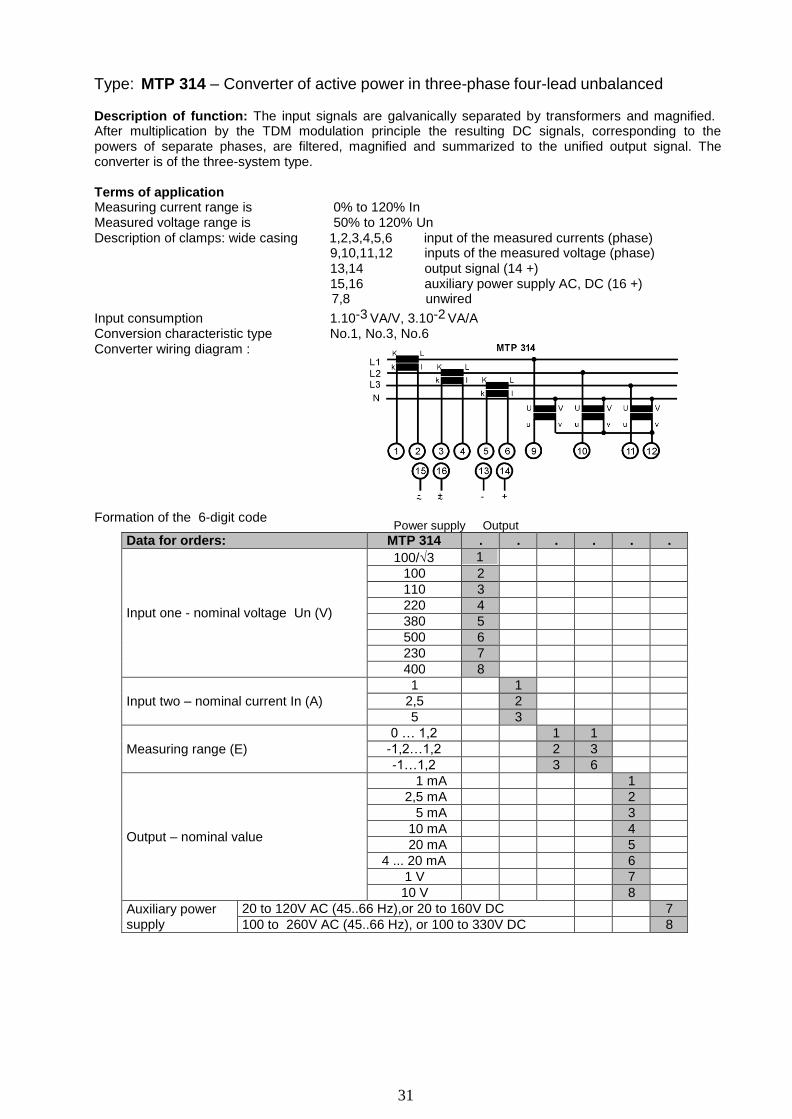
Type: MTP 314 – Converter of active power in three-phase four-lead unbalanced network Description of function: The input signals are galvanically separated by transformers and magnified.
31
After multiplication by the TDM modulation principle the resulting DC signals, corresponding to the powers of separate phases, are filtered, magnified and summarized to the unified output signal. The converter is of the three-system type.
Terms of application Measuring current range is 0% to 120% In Measured voltage range is 50% to 120% Un Description of clamps: wide casing 1,2,3,4,5,6 input of the measured currents (phase)
9,10,11,12 inputs of the measured voltage (phase) 13,14 output signal (14 +) 15,16 auxiliary power supply AC, DC (16 +) 7,8 unwired
Input consumption 1.10-3 VA/V, 3.10-2 VA/A Conversion characteristic type No.1, No.3, No.6 Converter wiring diagram :
Formation of the 6-digit code
Power supply Output
Data for orders: MTP 314 . . . . . .
Input one - nominal voltage Un (V)
100/√3 1 100 2 110 3 220 4 380 5 500 6 230 7 400 8
Input two – nominal current In (A)
1 1 2,5 2 5 3
Measuring range (E)
0 … 1,2 1 1 -1,2…1,2 2 3 -1…1,2 3 6
Output – nominal value
1 mA 1 2,5 mA 2
5 mA 3 10 mA 4 20 mA 5
4 ... 20 mA 6 1 V 7 10 V 8
Auxiliary power supply
20 to 120V AC (45..66 Hz),or 20 to 160V DC 7 100 to 260V AC (45..66 Hz), or 100 to 330V DC 8
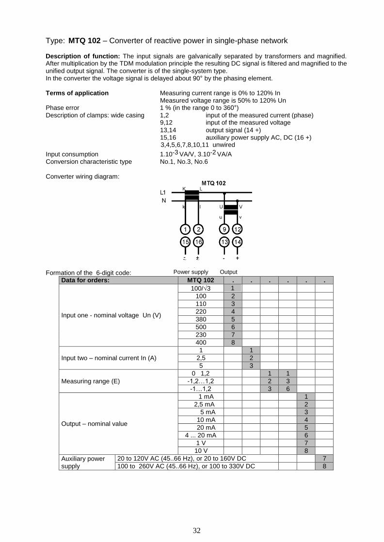
Type: MTQ 102 – Converter of reactive power in single-phase network
Description of function: The input signals are galvanically separated by transformers and magnified.
32
After multiplication by the TDM modulation principle the resulting DC signal is filtered and magnified to the unified output signal. The converter is of the single-system type. In the converter the voltage signal is delayed about 90° by the phasing element.
Terms of application Measuring current range is 0% to 120% In
Measured voltage range is 50% to 120% Un Phase error 1 % (in the range 0 to 360°) Description of clamps: wide casing 1,2 input of the measured current (phase)
9,12 input of the measured voltage
13,14 output signal (14 +) 15,16 auxiliary power supply AC, DC (16 +) 3,4,5,6,7,8,10,11 unwired
Input consumption 1.10-3 VA/V, 3.10-2 VA/A Conversion characteristic type No.1, No.3, No.6
Converter wiring diagram:
Formation of the 6-digit code:
Power supply Output
Data for orders: MTQ 102 . . . . . .
Input one - nominal voltage Un (V)
100/√3 1 100 2 110 3 220 4 380 5 500 6 230 7 400 8
Input two – nominal current In (A)
1 1 2,5 2 5 3
Measuring range (E)
0 1,2 1 1 -1,2…1,2 2 3 -1…1,2 3 6
Output – nominal value
1 mA 1 2,5 mA 2
5 mA 3 10 mA 4 20 mA 5
4 ... 20 mA 6 1 V 7 10 V 8
Auxiliary power supply
20 to 120V AC (45..66 Hz), or 20 to 160V DC 7 100 to 260V AC (45..66 Hz), or 100 to 330V DC 8

Type: MTQ 303 – Converter of reactive power in three-phase three-lead balanced network Description of function: The input signals are galvanically separated by transformers and magnified.
33
After multiplication by the TDM modulation principle the resulting DC signal, corresponding to the power of one phase, is filtered and magnified to the unified output signal. The converter is of the single-system type.
Terms of application
Measuring current range is 0% to 120% In Measured voltage range is 50% to 120% Un Description of clamps: wide casing 1,2 input of the measured current (phase)
10,11 inputs of the measured voltage (line voltage) 13,14 output signal (14 +) 15,16 auxiliary power supply AC, DC (16 +) 3,4,5,6,7,8,9,12 - unwired
Input consumption 1.10-3 VA/V, 3.10-2 VA/A Conversion characteristic type No.1, No.3,, No.6
Converter wiring diagram:
Formation of the 6-digit code:
Power supply Output
Data for orders: MTQ 303 . . . . . .
Input one - nominal voltage Un (V)
100/√3 1 100 2 110 3 220 4 380 5 500 6 230 7 400 8
Input two – nominal current In (A)
1 1 2,5 2 5 3
Measuring range (E)
0 1,2 1 1 -1,2…1,2 2 3 -1…1,2 3 6
Output – nominal value
1 mA 1 2,5 mA 2
5 mA 3 10 mA 4 20 mA 5
4 ... 20 mA 6 1 V 7 10 V 8
Auxiliary power supply
20 to 120V AC (45..66 Hz), or 20 to 160V DC 7 100 to 260V AC (45..66 Hz), or 100 to 330V DC 8

Type: MTQ 304 – Converter of reactive power in three-phase four-lead balanced network Description of function: The input signals are galvanically separated by transformers and magnified.
34
After multiplication by the TDM modulation principle the resulting DC signal is, corresponding to the power of one phase, filtered and magnified to the unified output signal. The converter is of the single- system type. The voltage system is connected to the line voltage.
Terms of application: Measuring current range is 0% to 120% In Measured voltage range is 50% to 120% Un Description of clamps: wide casing 1,2 input of the measured current (phase)
10,11 input of the measured voltage (line voltage, phase voltage is entered)
13,14 output signal (14 +) 15,16 auxiliary power supply AC, DC (16 +) 3,4,5,6,7,8,9,12 - unwired
Input consumption 1.10-3 VA/V, 3.10-2 VA/A Conversion characteristic type No.1, No.3, No.6
Converter wiring diagram:
Formation of the 6-digit code:
Power supply Output
Data for orders: MTQ 304 . . . . . .
Input one - nominal voltage Un (V)
100/√3 1 100 2 110 3 220 4 380 5 500 6 230 7 400 8
Input two – nominal current In (A)
1 1 2,5 2 5 3
Measuring range (E)
0 1,2 1 1 -1,2…1,2 2 3 -1…1,2 3 6
Output – nominal value
1 mA 1 2,5 mA 2
5 mA 3 10 mA 4 20 mA 5
4 .. 20 mA 6 1 V 7 10 V 8
Auxiliary power supply
20 to 120V AC (45..66 Hz), or 20 to 160V DC 7 100 to 260V AC (45..66 Hz), or 100 to 330V DC 8

Type: MTQ 313 – Converter of reactive power in three-phase three-lead unbalanced network Description of function: The input signals are galvanically separated by transformers and magnified. After multiplication by the TDM modulation principle the resulting DC signals, corresponding to the powers in separate phases, are filtered, summarized and magnified to the unified output signal. The
35
converter is of the two-system type of the Aron interconnection with the artificial zero.
Terms of application: Measuring current range is 0% to 120% In Measured voltage range is 50% to 120% Un Description of clamps: wide casing 1,2,5,6 input of the measured currents (phase)
9,10,11 input of the measured voltage (line
voltage)
13,14 output signal (14 +)
15,16 auxiliary power supply AC, DC (16 +)
3,4,7,8,12 - unwired
Input consumption 1.10-3 VA/V, 3.10-2 VA/A
Conversion characteristic type No.1, No.3, No.6
Converter wiring diagram: Two wirings possible
Power supply Output Power supply Output
Formation of the 6-digit code:
Data for orders: MTQ 313 . . . . . . Input one - nominal voltage Un (V)
100 2 380 5 400 8
Input two – nominal current In (A)
1 1 2,5 2 5 3
Measuring range (E)
0 1,2 1 1 -1,2…1,2 2 3 -1…1,2 3 6
Output – nominal value
1 mA 1 2,5 mA 2
5 mA 3 10 mA 4 20 mA 5
4 ... 20 mA 6 1 V 7 10 V 8
Auxiliary power supply
20 to 120V AC (45..66 Hz), or 20 to 160V DC 7 100 to 260V AC (45..66 Hz), or 100 to 330V DC 8

Type: MTQ 314 – Converter of reactive power in three-phase four-lead unbalanced network Description of function: The input signals are galvanically separated by transformers and magnified. After multiplication by the TDM modulation principle the resulting DC signals, corresponding to the powers in separate phases, are filtered, summarized and magnified to the unified output signal. The
36
converter is of the three-system. The voltage systems are connected to the line voltage.
Terms of application: Measuring current range is 0% to 120% In Measured voltage range is 50% to 120% Un Description of clamps: wide casing 1,2,3,4,5,6 input of the measured currents
9,10,11 input of the measured voltage (line,
phase voltage is entered)
13,14 output signal (14 +)
15,16 auxiliary power supply AC, DC (16 +)
7,8,12 - unwired
Input consumption 1.10-3 VA/V, 3.10-2 VA/A
Conversion characteristic type No.1, No.3, No.6
Converter wiring diagram:
Power supply Output
Formation of the 6-digit code:
Data for orders: MTQ 314 . . . . . . Input one - nominal voltage Un (V)
100/√3 1 220 4 230 7
Input two – nominal current In (A)
1 1 2,5 2 5 3
Measuring range (E)
0 1,2 1 1 -1,2…1,2 2 3 -1…1,2 3 6
Output – nominal value
1 mA 1 2,5 mA 2
5 mA 3 10 mA 4 20 mA 5
4 ... 20 mA 6 1 V 7 10 V 8
Auxiliary power supply
20 to 120V AC (45..66 Hz), or 20 to 160V DC 7 100 to 260V AC (45..66 Hz), or 100 to 330V DC 8
37
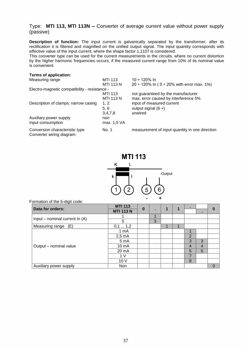
Type: MTI 113, MTI 113N – Converter of average current value without power supply (passive)
Description of function: The input current is galvanically separated by the transformer, after its rectification it is filtered and magnified on the unified output signal. The input quantity corresponds with effective value of the input current, where the shape factor 1,1107 is considered. This converter type can be used for the current measurements in the circuits, where no current distortion by the higher harmonic frequencies occurs, if the measured current range from 10% of its nominal value is convenient.
Terms of application: Measuring range
MTI 113
10 ÷ 120% In
MTI 113 N 20 ÷ 120% In ( 0 ÷ 20% with error max. 1%) Electro-magnetic compatibility - resistance -
Description of clamps: narrow casing
MTI 113 MTI 113 N 1, 2
not guaranteed by the manufacturer max. error caused by interference 5% input of measured current
5, 6 output signal (6 +)
Auxiliary power supply 3,4,7,8 non
unwired
Input consumption max. 1,5 VA
Conversion characteristic type Converter wiring diagram:
No. 1 measurement of input quantity in one direction
-Output
Formation of the 6-digit code:
Data for orders: MTI 113
0
.
1
1 .
0 MTI 113 N .
Input – nominal current In (A) 1 1 5 3
Measuring range (E) 0,1 ... 1,2 1 1
Output – nominal value
1 mA 1 2,5 mA 2
5 mA 3 3 10 mA 4 4 20 mA 5 5
1 V 7 10 V 8
Auxiliary power supply Non 0

Type MTI 114, MTI 114N - Converter of average current value
Description of function: The input signal is galvanically separated by the transformer, after its
38
rectification it is filtered and magnified to the unified output signal. The output is calibrated in units of the current effective value, where the shape factor 1,1107 is considered.
This converter type can be used for the current measurements in the circuits, where no current distortion by the higher harmonic frequencies occurs.
In its modified execution the type MTI 114N can be supplied from the mains 230V 50 Hz (60 Hz) only and has got limited choice of outputs to 10 mA, 20 mA and from 4 to 20 mA.
Terms of application: Measuring range 0% to 120% In, Description of clamps: narrow casing 1,2, 3 measured current input (clamp 1 – common,
2 – In=1A, 3 – In=5A, only one of clamps 2, 3 can be connected)
5, 6 output signal (6 +) 7, 8 auxiliary power supply AC, DC (8 +) 4 unwired
Input consumption 3.10-2 VA/A Conversion characteristic type: No. 1 measurement of input quantity in one direction
Converter wiring diagram: (at the execution supplied along the line the clamps 7 and 8 are unwired)
for the input current 1A for the input current 5A
Power supply Output Power supply Output
Unwired Unwired
Formation of the 6-digit code:
6-digit code: Type 0 Input Range Course Output Supply
Ordering: MTI 114
0
1
1
1 . .
MTI 114 N . . Input - nominal current In 1A and 5A 1
Measuring range (E) 0 ... 1,2 1 1
Output - nominal value
1 mA 1
2,5 mA 2
5 mA 3
10 mA 4 4 20 mA 5 5
4…20 mA 6 6
1 V 7
10 V 8
Auxiliary power supply
230V AC ( 50, 60 Hz) 6
20 to 120V AC (45 .. 66 Hz), or 20 to 160V DC 7 100 to 260V AC (45 .. 66 Hz), or 100 to 330V DC 8
Power supply along the output line 9
Note: The execution supplied along the line MTI 114 011169

Type: MTI 115, MTI 115N Converter of true effective current value
Description of function: The input signal is galvanically separated by the transformer, furthermore it is
39
processed by the circuit for the analogical calculation of the effective value. The resulting DC signal filtered and magnified to the unified output signal.
This converter type can be used for the current measurements in the circuits, i.e even in places, where current distortions by the higher harmonic frequencies occur (e.g. rectifiers, frequency converters, circuits with phase control, etc.).
In its modified execution the type MTI 115N can be supplied from the mains 230V 50 Hz (60 Hz) only and has got limited choice of outputs to 10 mA, 20 mA and from 4 to 20 mA.
Terms of application Measuring range 0% to 120% In Description of clamps: narrow casing 1,2, 3 measured current input (clamp 1 – common,
2 – In=1A,
3 – In=5A, only one of clamps 2, 3 can be connected)
5, 6 output signal (6 +)
7, 8 auxiliary power supply AC, DC (8 +) 4 unwired
Input consumption 3.10-2 VA/A
Conversion characteristic type: No. 1 measurement of input quantity in one direction
Converter wiring diagram: (the execution supplied along the line has got the clamps 7 and 8 unwired) for input current 1A for input current 5A
Power supply Output Power supply Output
Unwired
Formation of the 6-digit code:
6-digit code:
Unwired
Type 0 Input Range Course
Output Supply
Ordering:
Input - nominal current In
Measuring range (E)
Output - nominal value
Auxiliary power supply
MTI 115 . . 0 1 1 1
MTI 115 N . . 1A and 5A 1
0 ... 1,2 1 1
1 mA 1
2,5 mA 2
5 mA 3
10 mA 4 4
20 mA 5 5
4…20 mA 6 6
1 V 7
10 V 8
230V AC ( 50, 60 Hz) 6
20 to 120V AC (45 .. 66 Hz), or 20 to 160V DC 7
100 to 260V AC (45 .. 66 Hz), or 100 to 330V DC 8
Power supply along the output line 9
Note: The execution supplied along the line MTI 114 011169

Type: MTU 113 – Converter of average voltage value without power supply (passive)
Description of function: The input signal is galvanically separated by the measuring transformer,
40
Output
assembled inside the converter. Then it is rectified and filtered. The input is calibrated in units of the voltage effective value, where the shape factor 1,107 is considered.
This converter type can be used for the voltage measurements in the circuits, where no current distortion by the higher harmonic frequencies occurs, in case the range of the measured voltage from 50% is convenient.
Terms of application Measuring range 50 ÷ 120% Un Electro-magnetic compatibility - resistance – it is not guaranteed by the manufacturer Description of clamps: narrow casing 3, 4 measured voltage input
5, 6 output signal (6 +) 1,2,5,6 unwired
Auxiliary power supply non Input consumption max. 2 VA Output – current 0..1; 0...2,5; 0...5; 0...10mA Conversion characteristic type No.1 measurement of input quantity in one direction Converter wiring diagram
Output
Formation of the 6-digit code:
Data for orders: MTU 113 . 0 1 1 . 0
Input - nominal voltage Un (V)
100/√3 1 100 2 120 3 220 4 380 5 500 6 230 7 400 8
Measuring range (E) 0,5 ... 1,2 1 1
Output – nominal value (current)
1 mA 1 2,5 mA 2
5 mA 3 10 mA 4
Auxiliary power supply non 0

Type: MTU 114, MTU 114N – Converter of average voltage value
Description of function: The input signal is galvanically separated by the measuring transformer,
41
assembled inside the converter. Furthermore it is rectified, filtered and magnified to the unified output signal. The output is calibrated in units of the voltage effective value, where the shape factor 1,107 is considered. This converter type can be used for the voltage measurements in the circuits, where no current distortion by the higher harmonic frequencies occurs.
In its modified execution the type MTU 114N can be supplied from the mains 230V 50 Hz (60 Hz) only and has got limited choice of outputs to 10 mA, 20 mA and from 4 to 20 mA.
Terms of application Measuring range 0 ÷ 120% Un Description of clamps: narrow casing 3, 4 measuring voltage input
5, 6 output signal (6 +)
7, 8 auxiliary power supply (8+)
1,2 unwired
Input consumption 2.10-3 VA/V Conversion characteristic type No.1, measurement of input quantity in one direction
Converter wiring diagram: (the execution supplied along the line has got the clamps 7 and 8 unwired)
Power supply Output
Formation of the 6-digit code:
6-digit code:
Type Input 0 Range Course
Output Supply
MTU 114 . . Ordering: . 0 1 1
MTU 114 N . . 100/√3 V 1
100 V 2
110 V 3
Input - nominal current Un
Measuring range € Ouput
- nominal value
Auxiliary power supply
220 V 4
380 V 5
500 V 6
230 V 7
400 V 8
0 ... 1,2 1 1
1 mA 1
2,5 mA 2
5 mA 3
10 mA 4 4
20 mA 5 5
4…20 mA 6 6
1 V 7
10 V 8
230V AC ( 50, 60 Hz) 6
20 to 120V AC (45 .. 66 Hz), or 20 to 160V DC 7
100 to 260V AC (45 .. 66 Hz), or 100 to 330V DC 8
Power supply along the output line 9
Note: The execution supplied along the line MTU 114. 01169
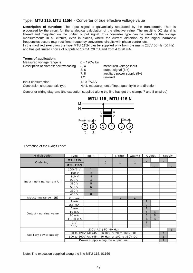
Type: MTU 115, MTU 115N - Converter of true effective voltage value
42
Description of function: The input signal is galvanically separated by the transformer. Then is processed by the circuit for the analogical calculation of the effective value. The resulting DC signal is filtered and magnified on the unified output signal. This converter type can be used for the voltage measurements in all circuits, even in places, where the current distortion by the higher harmonic frequencies occurs (e.g. rectifiers, frequency converters, circuits with phase control etc. In the modified execution the type MTU 115N can be supplied only from the mains 230V 50 Hz (60 Hz)
and has got limited choice of outputs to 10 mA, 20 mA and from 4 to 20 mA.
Terms of application: Measured voltage range is 0 ÷ 120% Un Description of clamps: narrow casing 3, 4 measured voltage input
5, 6 output signal (6 +)
7, 8 auxiliary power supply (8+)
1,2 unwired
Input consumption 1.10-3 VA/V Conversion characteristic type No.1, measurement of input quantity in one direction
Converter wiring diagram: (the execution supplied along the line has got the clamps 7 and 8 unwired)
Power supply Output
Formation of the 6-digit code:
6-digit code: T ype Input 0 R ange C ourse O u tput S upply
M T U 115 . . O rde ring: . 0 1 1
M T U 115N . . 100/√ 3 V 1
100 V 2
110 V 3
Input - nom inal current U n
M easuring range (E )
O u tput - nom inal va lu e
A u x ilia ry p o w e r s upply
220 V 4
380 V 5
500 V 6
230 V 7
400 V 8
0 ... 1 ,2 1 1
1 m A 1
2,5 m A 2
5 m A 3
10 m A 4 4
20 m A 5 5
4… 20 m A 6 6
1 V 7
10 V 8
230V A C ( 50, 60 H z) 6
20 to 120V A C (45 .. 66 H z), or 20 to 160V D C 7
100 to 260V A C (45 .. 66 H z), or 100 to 330V D C 8
P o w e r supply along the output lin e 9
Note: The execution supplied along the line MTU 115. 01169

43
Type: MTI 111, MTI 111 N - Converter of DC current ( < 100 mA)
MTI 112, MTI 112 N - Converter of DC current ( ≥ 100 mA)
Description of function: The input current is scanned as a voltage drop on the shunt, increased by the magnifier and separated galvanically by the optic transferring element. After filtration it is adapted to the unified output signal. The output quantity corresponds to the average value of the input current. This converter type can be used for the current measurement in the circuits, where current distortion by the AC signal (peak - peak) is below 50% of the measured value (momentary current value must be exceed the limits of the measured current).
In their modified execution the types MTI 111N and MTI 112N are power supplied only from the mains 230V 50 Hz (60 Hz) and limited selection of outputs to 10 mA, 20 mA and 4 to 20 mA.
Terms of application:
Measured current range is 0 ÷ 120% In
Description of clamps: narrow casing 1, 2 measured current input (1 +) 5, 6 output signal (6 +) 7, 8 auxiliary power supply (8+) 3, 4 unwired
Input consumption MTI 111 < 0,07W (voltage drop approx. 1V) MTI 112 < 0,4W (voltage drop approx. 0,06V)
Conversion characteristic type No.1, measurement of input quantity in one direction No.3, measurement of input quantity in both directions No.6, measurement of input quantity in both directions with the output of
one polarity
Converter wiring diagram: (the execution supplied along the line has got the clamps 7 and 8 unwired)
Power supply Output
Formation of the 6-digit code:
Ordering: MTI 111 MTI 112
0
. . . . .
MTI 111N MTI 112N . . . . Input – nominal current In
1 mA 100 mA 1 2,5 mA 250 mA 2 5 mA 500 mA 3 10 mA 1 A 4 25 mA 2,5 A 5 50 mA 5 A 6
Measuring range (E)
0 ... 1,2 1 1 1 1 -1,2 .. 0 .. 1,2 2 3 -1 .. 0 .. 1,2 3 6
Output – nominal value
1 mA 1 2,5 mA 2
5 mA 3 3 10 mA 4 4 20 mA 5 5
4 ... 20 mA 6 1 V 7 10 V 8
Auxiliary power supply
230V AC ( 45 to 66 Hz) 6 20 to 120V AC (45 to 66 Hz), 20 to 160V DC 7 100 to 260V AC (45 to 66 Hz), 100 to 330V DC 8 Power supply along the output line 9
Note: The execution supplied along the line MTI 11.0 … 69

44
Type: MTU 111, MTU 111 N - Converter of DC voltage ( < 1 V)
MTU 112, MTU 112 N - Converter of DC voltage ( ≥ 1 V)
Description of function: The input voltage is increased by the magnifier and separated galvanically by the optic transferring element. After filtration it is adapted to the unified output signal. The quantity corresponds to the average value of the input voltage. This converter type can be used for the voltage measurements in the circuits, where voltage distortion by the AC signal (peak - peak) is below 50% of the measured value (momentary voltage value must not exceed the limits of the measured voltage range).
In their modified execution the types MTU 111N and MTU 112N are power supplied only from the mains 230V 50 Hz (60 Hz) and limited selection of outputs to 10 mA, 20 mA and 4 to 20 mA.
Terms of application: Measured voltage range is 0 ÷ 120% Un Description of clamps: narrow casing 3, 4 measured voltage input (3 +)
5, 6 output signal (6 +)
7, 8 auxiliary power supply (8+)
1, 2 unwired Input consumption < 6x10
-4W/V
Conversion characteristic type No.1, measurement of input quantity in one direction No.3, measurement of input quantity in both direction
No.6, measurement of input quantity in one direction with the output of one polarity
Converter wiring diagram: (the execution supplied along the line has got the clamps 7 and 8 unwired)
Power supply Output
Formation of the 6-digit code:
Ordering: MTU 111 MTU 112
.
0 . . . .
MTU 111N MTU 112N . . . .
Input – nominal voltage
Un (V)
50 mV 1 1 60 mV 2,5 2
100 mV 5 3 150 mV 10 4 250 mV 25 5 500 mV 50 6
100 7 250 8 500 9
Measuring range (E)
0 ... 1,2 1 1 1 1 -1,2 .. 0 .. 1,2 2 3 -1 .. 0 .. 1,2 3 6
Output – nominal value
1 mA 1 2,5 mA 2
5 mA 3 3 10 mA 4 4 20 mA 5 5
4 ... 20 mA 6 1 V 7 10 V 8
Auxiliary power supply
230V AC ( 45 to 66 Hz) 6 20 to 120V AC (45 to 66 Hz), 20 to 160V DC 7 100 to 260V AC (45 to 66 Hz), 100 to 330V DC 8 Power supply along the output line 9
Note: The execution supplied along the line MTU 11. .0..69
Execution MTU 111N, MTU 112N – only measuring range 0…1,2 0 . 1 1 . 6

45
Type: MTF 115 - Frequency converter
Description of function: The input voltage signal is separated galvanically by the optic element. After its shaping by the comparator it can be used for starting of the mono-stable toggle circuit. The measurement stability is derived from the quartz-controlled oscillator. The output signal from the mono-stable circuit is filtered and magnified to the unified output signal. Owing to the functional principle the output signal fluctuates, in dependence on the measured frequency, within the limits of the instrument accuracy class.
Terms of application: Measuring range (E) 48.... 52 Hz, 45.... 55 Hz Input signal range 50% to 120% Un
Input consumption approx. 2.10-3 VA/V
Description of clamps: narrow casing 3, 4 input of measured voltage signal
5, 6 output signal (6 +)
1,2,7,8 unwired Accuracy class 100 mHz Conversion characteristic type: No.2 Converter wiring diagram:
Output line
Formation of the 6-digit code:
Ordering: MTF 105 . 0 . 2 6 9
Input - nominal voltage Un (V)
100/√3 1 100 2 120 3 220 4 380 5 500 6 230 7 400 8
Measuring range (E) 48…52 Hz 1 2 45…55 Hz 2 2
Output – nominal value 4 ... 20 mA 6 Power supply along the line 9
-

46
Outsights, common inquiries: The converters MTU 104, MTU 105, MTU 114, MTU 115, MTI 104, MTI 105, MTI 114, MTI 115 measure up to approx. 150% Un, In with an error typically <1%. (in case the term max. 15V on the converter output is fulfilled – i.e. less load resistance at the current output). At the converters MTU 103, MTU 104, MTU 105, MTI 103, MTI 104, MTI 105 the output can reach two-fold nominal output value, in case the input is overloaded. At the converters MTU 114, MTU 115, MTI 114, MTI 115 the max. value on the output, at the overloaded input, is limited to approx. 150% of the output nominal value, this value can be changed after an agreement with the manufacturer. At the signal distorted by the higher harmonic frequencies the converters measure up to the amplitude of the input signal of 200% of the nominal value, at the converters MTU 104, MTU 114, MTI 104 and MTI 114 an error occurs, which is given by the signal shape factor, the converters MTU 105, MTU 115, MTI 105 and MTI 115 measure, for the shape factor <3 with the error within the frame of the instrument accuracy, for the shape factor 3 .. 7 with the additional error approx. 1%. The power converter MTP and MTQ in all their executions process the input voltage also in the range from 0% to 50% of the voltage with the error typically <1%. At the power converters connection the connection of the separate phase is important. To the given phase the relevant current acc. to the wiring diagram. At the reactive power converters also the phase sequence is important (sense of rotation), see the wiring diagrams again. For orders of the converters at the single-phase converters and at the three-phase four-lead network converters the phase voltage is to be entered, at the converters to the three-phase three-lead network the line voltage is to be entered. The same rule can be applied for the print of the labels on the converters. At the power converters the set power can be adjusted at the given transmission transformers, this fact is then specified on the label – the transmission ratios of the voltage and current transformers and given power belonging to the out nominal value. Additional adjustment of such power can be performed within the range approx. 40 to 160% of the nominal power (the power calculated from the input quantities at presumed cos fi = 1). The energy supply circuits of the converters are designed with regard to the DC supply voltage use by means of the converter. The improved versions 7 and 8 have got their increased immunity against the interference and over- voltage peaks in the supply network, acc. to the standard ČSN EN 61000-6-2 they are resistant against the over- voltage peaks up to 2kV. In case the over-voltage with its values near, or over 2 kV, we recommend a filter installation to the power supply, with the over-voltage protection preferably. (e.g. in shops with large machines with the phase, or frequency regulation etc.) Possibility of backup of the converters (source version 8):
Connection way of more converters supplied along the line to one supply source
Presumption: For the power supply of one converter the source must deliver 30 mA. For „n“ converters it must be n x 30 mA. The size of the scanning resistors must be selected acc. to the term – see chapter Technical data – page No.6 Wiring: Example of three converters connection to one source Uzd.
The outputs from the individual converters are the voltage drops on the resistors Rs.
At the Rs selection the resistance of the metallic loop line must be considered, the converters are often dislocated in sizable distances and the line resistance is not insignificant. A condition must be valid permanently, that the total resistance of the output loop Rn is the sum of the line leads resistances, the inner resistance of the source Uzd and the scanning resistance of the resistor Rs.
BAT – Battery with voltage C – Condenser with capacity n*2uF where n is number of transducers

47
PRODUCTS OF METRA BLANSKO
DIGITAL & ANALOG INSTRUMENTS TRANSDUCERS
SHUNTS
CALIBRACIONS & SERVICES
REVISION INSTRUMENTS
RAILWAY SPEEDOMETER
MORE INFORMATIONS ON: www.metra.cz/en/ [email protected] +420 602 410 258