Chapter 12 Quantities, Costs, and Specifications - Bridge ...
48
WSDOT Bridge Design Manual M 23-50.21 Page 12-i June 2022 Chapter 12 Quantities, Costs, and Specifications Contents 12.1 Quantities - General ....................................................... 12-1 12.1.1 Cost Estimating Quantities ............................................. 12-1 12.1.1.A Conceptual Stage .......................................... 12-1 12.1.1.B Preliminary Plan Stage ...................................... 12-1 12.1.1.C Design Stage .............................................. 12-1 12.1.1.D Final Contract Quantities ..................................... 12-1 12.1.2 Not Included in Bridge Quantities List ..................................... 12-1 12.2 Computation of Quantities.................................................. 12-2 12.2.1 Responsibilities ...................................................... 12-2 12.2.1.A Design Unit ............................................... 12-2 12.2.1.B Bridge Project Support Unit ................................... 12-2 12.2.2 Procedure for Computation ............................................. 12-2 12.2.3 Data Source ........................................................ 12-3 12.2.4 Accuracy ........................................................... 12-3 12.2.4.A Preliminary Quantities ....................................... 12-3 12.2.4.B Final Quantities ............................................ 12-3 12.2.5 Excavation ......................................................... 12-3 12.2.5.A Structure Excavation, Class A ................................. 12-3 12.2.5.B Special Excavation ......................................... 12-5 12.2.6 Shoring or Extra Excavation, Class A ..................................... 12-6 12.2.7 Piling .............................................................. 12-8 12.2.8 Conduit Pipe ........................................................ 12-8 12.2.9 Private Utilities Attached To Bridge Structures .............................. 12-9 12.2.10 Drilled Shafts........................................................ 12-9 12.3 Construction Costs ...................................................... 12-10 12.3.1 Introduction ........................................................ 12-10 12.3.2 Factors Affecting Costs ............................................... 12-10 12.3.2.A Type of Structure .......................................... 12-10 12.3.2.B Location of Project Site ..................................... 12-10 12.3.2.C Size of Project Contract..................................... 12-10 12.3.2.D Foundation Requirements ................................... 12-10 12.3.2.E Sequencing of Project ...................................... 12-10
-
Upload
khangminh22 -
Category
Documents
-
view
0 -
download
0
Transcript of Chapter 12 Quantities, Costs, and Specifications - Bridge ...

WSDOT Bridge Design Manual M 23-50.21 Page 12-i June 2022
Chapter 12 Quantities, Costs, and Specifications Contents
12.1 Quantities - General . . . . . . . . . . . . . . . . . . . . . . . . . . . . . . . . . . . . . . . . . . . . . . . . . . . . . . . 12-112.1.1 Cost Estimating Quantities . . . . . . . . . . . . . . . . . . . . . . . . . . . . . . . . . . . . . . . . . . . . . 12-1
12.1.1.A Conceptual Stage . . . . . . . . . . . . . . . . . . . . . . . . . . . . . . . . . . . . . . . . . . 12-112.1.1.B Preliminary Plan Stage . . . . . . . . . . . . . . . . . . . . . . . . . . . . . . . . . . . . . . 12-112.1.1.C Design Stage. . . . . . . . . . . . . . . . . . . . . . . . . . . . . . . . . . . . . . . . . . . . . . 12-112.1.1.D Final Contract Quantities. . . . . . . . . . . . . . . . . . . . . . . . . . . . . . . . . . . . . 12-1
12.1.2 Not Included in Bridge Quantities List. . . . . . . . . . . . . . . . . . . . . . . . . . . . . . . . . . . . . 12-1
12.2 Computation of Quantities. . . . . . . . . . . . . . . . . . . . . . . . . . . . . . . . . . . . . . . . . . . . . . . . . . 12-212.2.1 Responsibilities . . . . . . . . . . . . . . . . . . . . . . . . . . . . . . . . . . . . . . . . . . . . . . . . . . . . . . 12-2
12.2.1.A Design Unit . . . . . . . . . . . . . . . . . . . . . . . . . . . . . . . . . . . . . . . . . . . . . . . 12-212.2.1.B Bridge Project Support Unit. . . . . . . . . . . . . . . . . . . . . . . . . . . . . . . . . . . 12-2
12.2.2 Procedure for Computation. . . . . . . . . . . . . . . . . . . . . . . . . . . . . . . . . . . . . . . . . . . . . 12-212.2.3 Data Source . . . . . . . . . . . . . . . . . . . . . . . . . . . . . . . . . . . . . . . . . . . . . . . . . . . . . . . . 12-312.2.4 Accuracy . . . . . . . . . . . . . . . . . . . . . . . . . . . . . . . . . . . . . . . . . . . . . . . . . . . . . . . . . . . 12-3
12.2.4.A Preliminary Quantities . . . . . . . . . . . . . . . . . . . . . . . . . . . . . . . . . . . . . . . 12-312.2.4.B Final Quantities . . . . . . . . . . . . . . . . . . . . . . . . . . . . . . . . . . . . . . . . . . . . 12-3
12.2.5 Excavation . . . . . . . . . . . . . . . . . . . . . . . . . . . . . . . . . . . . . . . . . . . . . . . . . . . . . . . . . 12-312.2.5.A Structure Excavation, Class A. . . . . . . . . . . . . . . . . . . . . . . . . . . . . . . . . 12-312.2.5.B Special Excavation . . . . . . . . . . . . . . . . . . . . . . . . . . . . . . . . . . . . . . . . . 12-5
12.2.6 Shoring or Extra Excavation, Class A . . . . . . . . . . . . . . . . . . . . . . . . . . . . . . . . . . . . . 12-612.2.7 Piling . . . . . . . . . . . . . . . . . . . . . . . . . . . . . . . . . . . . . . . . . . . . . . . . . . . . . . . . . . . . . . 12-812.2.8 Conduit Pipe . . . . . . . . . . . . . . . . . . . . . . . . . . . . . . . . . . . . . . . . . . . . . . . . . . . . . . . . 12-812.2.9 Private Utilities Attached To Bridge Structures . . . . . . . . . . . . . . . . . . . . . . . . . . . . . . 12-912.2.10 Drilled Shafts. . . . . . . . . . . . . . . . . . . . . . . . . . . . . . . . . . . . . . . . . . . . . . . . . . . . . . . . 12-9
12.3 Construction Costs . . . . . . . . . . . . . . . . . . . . . . . . . . . . . . . . . . . . . . . . . . . . . . . . . . . . . . 12-1012.3.1 Introduction . . . . . . . . . . . . . . . . . . . . . . . . . . . . . . . . . . . . . . . . . . . . . . . . . . . . . . . . 12-1012.3.2 Factors Affecting Costs . . . . . . . . . . . . . . . . . . . . . . . . . . . . . . . . . . . . . . . . . . . . . . . 12-10
12.3.2.A Type of Structure. . . . . . . . . . . . . . . . . . . . . . . . . . . . . . . . . . . . . . . . . . 12-1012.3.2.B Location of Project Site . . . . . . . . . . . . . . . . . . . . . . . . . . . . . . . . . . . . . 12-1012.3.2.C Size of Project Contract. . . . . . . . . . . . . . . . . . . . . . . . . . . . . . . . . . . . . 12-1012.3.2.D Foundation Requirements. . . . . . . . . . . . . . . . . . . . . . . . . . . . . . . . . . . 12-1012.3.2.E Sequencing of Project . . . . . . . . . . . . . . . . . . . . . . . . . . . . . . . . . . . . . . 12-10

Chapter 12 Quantities, Costs, and Specifications
Page 12-ii WSDOT Bridge Design Manual M 23-50.21 June 2022
12.3.3 Development of Cost Estimates . . . . . . . . . . . . . . . . . . . . . . . . . . . . . . . . . . . . . . . . 12-1112.3.3.A Types. . . . . . . . . . . . . . . . . . . . . . . . . . . . . . . . . . . . . . . . . . . . . . . . . . . 12-11
12.3.3.A.1 Prospectus and Project Summary Estimates . . . . . . . . . 12-1112.3.3.A.2 Preliminary Design Estimates. . . . . . . . . . . . . . . . . . . . . 12-1112.3.3.A.3 Estimate Updates During Design . . . . . . . . . . . . . . . . . . 12-1112.3.3.A.4 Contract Estimates . . . . . . . . . . . . . . . . . . . . . . . . . . . . . 12-11
12.3.3.B Responsibilities . . . . . . . . . . . . . . . . . . . . . . . . . . . . . . . . . . . . . . . . . . . 12-1212.3.3.B.1 Bridge Project Support Unit . . . . . . . . . . . . . . . . . . . . . . 12-1212.3.3.B.2 Designer . . . . . . . . . . . . . . . . . . . . . . . . . . . . . . . . . . . . . 12-12
12.3.3.C Documentation . . . . . . . . . . . . . . . . . . . . . . . . . . . . . . . . . . . . . . . . . . . 12-1212.3.3.D Cost Data . . . . . . . . . . . . . . . . . . . . . . . . . . . . . . . . . . . . . . . . . . . . . . . 12-12
12.3.3.D.1 General . . . . . . . . . . . . . . . . . . . . . . . . . . . . . . . . . . . . . . 12-1212.3.3.D.2 Deck or Wall Face Area . . . . . . . . . . . . . . . . . . . . . . . . . 12-1212.3.3.D.3 Bridge Widenings and New Bridges . . . . . . . . . . . . . . . . 12-1312.3.3.D.4 Bridge Rail Replacement . . . . . . . . . . . . . . . . . . . . . . . . 12-1312.3.3.D.5 Bridge Lengths With Unequal Wingwalls . . . . . . . . . . . . 12-1312.3.3.D.6 Retaining Walls. . . . . . . . . . . . . . . . . . . . . . . . . . . . . . . . 12-13
12.4 Construction Specifications and Estimates. . . . . . . . . . . . . . . . . . . . . . . . . . . . . . . . . . . 12-1412.4.1 General . . . . . . . . . . . . . . . . . . . . . . . . . . . . . . . . . . . . . . . . . . . . . . . . . . . . . . . . . . . 12-1412.4.2 Definitions . . . . . . . . . . . . . . . . . . . . . . . . . . . . . . . . . . . . . . . . . . . . . . . . . . . . . . . . . 12-14
12.4.2.A Standard Specifications . . . . . . . . . . . . . . . . . . . . . . . . . . . . . . . . . . . . . 12-1412.4.2.B Mandatory General Special Provisions . . . . . . . . . . . . . . . . . . . . . . . . . 12-1412.4.2.C Special Provisions. . . . . . . . . . . . . . . . . . . . . . . . . . . . . . . . . . . . . . . . . 12-1412.4.2.D Addendum. . . . . . . . . . . . . . . . . . . . . . . . . . . . . . . . . . . . . . . . . . . . . . . 12-1412.4.2.E AD Copy . . . . . . . . . . . . . . . . . . . . . . . . . . . . . . . . . . . . . . . . . . . . . . . . 12-1412.4.2.F As defined in Standard Specifications Section 1-02.4. . . . . . . . . . . . . . 12-14
12.4.3 General Bridge S&E Process . . . . . . . . . . . . . . . . . . . . . . . . . . . . . . . . . . . . . . . . . . 12-1512.4.3.A Typical Reviews and Milestone Dates. . . . . . . . . . . . . . . . . . . . . . . . . . 12-1512.4.3.B Constructability Review Set Distribution . . . . . . . . . . . . . . . . . . . . . . . . 12-1512.4.3.C PS&E Review Set Distribution. . . . . . . . . . . . . . . . . . . . . . . . . . . . . . . . 12-16
12.4.4 Reviewing Bridge Plans . . . . . . . . . . . . . . . . . . . . . . . . . . . . . . . . . . . . . . . . . . . . . . 12-1612.4.4.A Job File . . . . . . . . . . . . . . . . . . . . . . . . . . . . . . . . . . . . . . . . . . . . . . . . . 12-1612.4.4.B PS&E Check List (Form 230-037 and Appendix 12.4-A1). . . . . . . . . . . 12-1612.4.4.C Summary of Quantities (Form 230-031 and Appendix 12.2-A1) . . . . . . 12-1712.4.4.D Plans . . . . . . . . . . . . . . . . . . . . . . . . . . . . . . . . . . . . . . . . . . . . . . . . . . . 12-1712.4.4.E Not Included in Bridge Quantities List (Form 230-038 and
Appendix 12.1-A1). . . . . . . . . . . . . . . . . . . . . . . . . . . . . . . . . . . . . . . . . 12-1712.4.4.F Geotechnical Report . . . . . . . . . . . . . . . . . . . . . . . . . . . . . . . . . . . . . . . 12-17
12.4.5 Preparing the Bridge Cost Estimates . . . . . . . . . . . . . . . . . . . . . . . . . . . . . . . . . . . . 12-1712.4.5.A General . . . . . . . . . . . . . . . . . . . . . . . . . . . . . . . . . . . . . . . . . . . . . . . . . 12-1712.4.5.B Procedure . . . . . . . . . . . . . . . . . . . . . . . . . . . . . . . . . . . . . . . . . . . . . . . 12-18
Quantities, Costs, and Specifications Chapter 12
WSDOT Bridge Design Manual M 23-50.21 Page 12-iii June 2022
12.4.6 Preparing the Bridge Specifications . . . . . . . . . . . . . . . . . . . . . . . . . . . . . . . . . . . . . 12-1812.4.6.A General . . . . . . . . . . . . . . . . . . . . . . . . . . . . . . . . . . . . . . . . . . . . . . . . . 12-1812.4.6.B Procedure . . . . . . . . . . . . . . . . . . . . . . . . . . . . . . . . . . . . . . . . . . . . . . . 12-18
12.4.7 Preparing the Bridge Working Day Schedule . . . . . . . . . . . . . . . . . . . . . . . . . . . . . . 12-1912.4.7.A General . . . . . . . . . . . . . . . . . . . . . . . . . . . . . . . . . . . . . . . . . . . . . . . . . 12-1912.4.7.B Procedure . . . . . . . . . . . . . . . . . . . . . . . . . . . . . . . . . . . . . . . . . . . . . . . 12-19
12.4.8 Reviewing Projects Prepared by Consultants. . . . . . . . . . . . . . . . . . . . . . . . . . . . . . 12-2012.4.8.A General . . . . . . . . . . . . . . . . . . . . . . . . . . . . . . . . . . . . . . . . . . . . . . . . . 12-2012.4.8.B Procedure . . . . . . . . . . . . . . . . . . . . . . . . . . . . . . . . . . . . . . . . . . . . . . . 12-20
12.4.9 Submitting the PS&E Package . . . . . . . . . . . . . . . . . . . . . . . . . . . . . . . . . . . . . . . . . 12-2012.4.9.A General . . . . . . . . . . . . . . . . . . . . . . . . . . . . . . . . . . . . . . . . . . . . . . . . . 12-20
12.4.10 PS&E Review Period and Turn-in for AD Copy. . . . . . . . . . . . . . . . . . . . . . . . . . . . . 12-2112.4.10.A Description . . . . . . . . . . . . . . . . . . . . . . . . . . . . . . . . . . . . . . . . . . . . . . 12-2112.4.10.B Procedure . . . . . . . . . . . . . . . . . . . . . . . . . . . . . . . . . . . . . . . . . . . . . . . 12-21
12.5 Appendices . . . . . . . . . . . . . . . . . . . . . . . . . . . . . . . . . . . . . . . . . . . . . . . . . . . . . . . . . . . . . 12-22Appendix 12.1-A1 Not Included In Bridge Quantities List . . . . . . . . . . . . . . . . . . . . . . . . . . 12-23Appendix 12.2-A1 Bridge Quantities. . . . . . . . . . . . . . . . . . . . . . . . . . . . . . . . . . . . . . . . . . 12-24Appendix 12.3-A1 Structural Estimating Aids Construction Costs . . . . . . . . . . . . . . . . . . . 12-29Appendix 12.3-A2 Structural Estimating Aids Construction Costs . . . . . . . . . . . . . . . . . . . 12-31Appendix 12.3-A3 Structural Estimating Aids Construction Costs . . . . . . . . . . . . . . . . . . . 12-33Appendix 12.3-A4 Structural Estimating Aids Construction Costs . . . . . . . . . . . . . . . . . . . 12-35Appendix 12.3-B1 Cost Estimate Summary . . . . . . . . . . . . . . . . . . . . . . . . . . . . . . . . . . . . 12-36Appendix 12.4-A1 Special Provisions Checklist . . . . . . . . . . . . . . . . . . . . . . . . . . . . . . . . . 12-37Appendix 12.4-A2 Structural Estimating Aids Construction Time Rates. . . . . . . . . . . . . . . 12-42Appendix 12.4-B1 Construction Working Day Schedule. . . . . . . . . . . . . . . . . . . . . . . . . . . 12-44

Chapter 12 Quantities, Costs, and Specifications
Page 12-iv WSDOT Bridge Design Manual M 23-50.21 June 2022
This page intentionally left blank.

WSDOT Bridge Design Manual M 23-50.21 Page 12-1 June 2022
Chapter 12 Quantities, Costs, and Specifications
12.1 Quantities - GeneralThe quantities of the various materials and work items involved in the construction of a project that includes bridges and structures are needed for establishing the estimated cost of the project throughout the design process, and for establishing a basis for comparison of the contractor’s bids.
12.1.1 Cost Estimating QuantitiesQuantities for establishing cost estimates are often necessary during various stages of project development and are required at the completion of the Bridge PS&E. These quantities should be calculated from the best information available at the time, see Section 12.2.3. The policy regarding the preparation of quantity calculations is as follows:
12.1.1.A Conceptual Stage
During the conceptual stage of a project, estimated quantities may be required to arrive at an estimated cost. The need for conceptual stage quantities will be determined by the Bridge Project Support Unit.
12.1.1.B Preliminary Plan Stage
Upon completion of the preliminary plan, estimated quantities may be required to arrive at an estimated cost. The need for preliminary plan stage quantities will be determined by the Bridge Project Support Unit.
12.1.1.C Design Stage
If requested, quantity calculations shall be made, reviewed, and submitted to the Bridge Project Support Unit by the Bridge Design Unit as the design progresses. The first submittal of estimated quantities shall be made as soon as the major dimensions of the structure are determined. As refinements in the design are made, quantities varying more than 10 percent from those previously submitted shall be resubmitted.
12.1.1.D Final Contract Quantities
Upon completion of structural design and plans, the quantities of materials and work items involved in the construction of the project shall be computed,. See Sections 12.2.2 and 12.2.4.B.
12.1.2 Not Included in Bridge Quantities ListItems of work which appear in the bridge plan sheets, but for which details, specifications, and quantities are not included in the Bridge PS&E, shall be listed in the “Not Included in Bridge Quantities List” (WSDOT Form 230-038 and Appendix 12.1-A1). This list is required for every bridge, even if no items of work are shown in the Plans that are in this category. (In this case, fill out the bridge information at the top of the form and write “NONE” across the form.) This form is transmitted to the Region Design PE Office with all Preliminary Plan submittals, all Bridge PS&E distributions, and at various milestone points during the design process, to ensure that the responsibility for all PS&E items is clear. Particular care shall be taken in the preparation of this list as omissions can result in an incomplete project PS&E with missing information for work items, or conflicting overlapping information for work items.

Chapter 12 Quantities, Costs, and Specifications
Page 12-2 WSDOT Bridge Design Manual M 23-50.21 June 2022
12.2 Computation of Quantities12.2.1 Responsibilities
12.2.1.A Design Unit
The Design Unit is responsible for calculating quantities required for cost estimates for Preliminary Plans prepared in Design Units, calculating preliminary quantities at various milestones during the design process, and calculating quantities for the final Bridge PS&E. The Design Unit is responsible for notifying the Region Design PE Office and the Bridge Project Support Unit whenever structural design changes and alterations are made to the design features and quantities which affect the cost of the structure, especially following the distribution of the initial Preliminary Plan.
12.2.1.B Bridge Project Support Unit
The Bridge Project Support Unit is responsible for computing quantities for conceptual stage cost estimates, and cost estimates for Preliminary Plans prepared in the Bridge Project Support Unit. The Bridge Project Support Unit is responsible for ensuring that the quantities listed in the AD Copy Bid Proposal correspond to those received from the Design Unit.
12.2.2 Procedure for ComputationQuantities are to be computed and checked independently. The designer/originator and checker shall separately summarize their calculated quantities on the Bridge Quantities Form 230-031 (See Appendix 12.2-A1) in the units shown thereon. The two summaries shall be submitted to the Design Unit Manager for comparison. The designer/originator and checker shall use identical breakdowns for each quantity. For example, the designer/originator’s quantities for excavation for each of Piers 1, 2, and 3 should be compared separately against the corresponding quantities made by the checker.
When the desired accuracy, see Section 12.2.4, is achieved, a Manager’s Bridge Quantities form shall be prepared and submitted to the Bridge Project Support Unit along with the Pre-Contract Review Bridge Plans review set. (This form is the same as previously mentioned except that it is labeled “Manager’s Bridge Quantities” and is completed by the Design Unit Manager or designee. If the Design Unit Manager elects, the designer/originator’s or the checker’s Bridge Quantities form may be designated as “Supervisor’s Bridge Quantities.”) This form is used by the Bridge Project Support Unit to prepare the final bridge cost estimate.
All quantity calculations and bridge quantities forms are to be filed in the job file for the structure or the PS&E file for the project. All subsequent revisions shall be handled in the same manner as the original quantities. On the “Bridge Quantities” form, any revision to the original figure should not be erased but crossed out and replaced by the new figure using a different colored pencil. If there are too many revisions, the old summary sheet should be marked void, left in the file, and a new sheet made out, marked “Revised,” dated, and the original forwarded to the Bridge Project Support Unit.
Mistakes in quantities can be very costly to Contracting Agency. The designer/originator and checker must account for all items of work on the “Bridge Quantities” form, and must also be careful to enter an item of work only once (e.g., concrete or steel rebar in the superstructure should not be entered both in the lump sum superstructure breakdown and in the unit bid item quantity).

Quantities, Costs, and Specifications Chapter 12
WSDOT Bridge Design Manual M 23-50.21 Page 12-3 June 2022
12.2.3 Data SourceQuantities of materials for use in preliminary cost estimates can often be obtained from the quantities calculated for previous similar designs. This information is available from the Bridge Project Support Unit.
12.2.4 Accuracy
12.2.4.A Preliminary Quantities
Quantities used for cost estimates prepared during the conceptual stage of the design are expected to have an accuracy of ± 10 percent. The first iteration of quantities, after the preliminary plan has been completed, is expected to have an accuracy of ± 5 percent.
12.2.4.B Final Quantities
Final quantities in the Bridge PS&E submittal, including bar list quantities, to be listed in the Special Provisions and Bid Proposal sheet of the AD Copy, are to be calculated to have an accuracy of ± 1 percent.
12.2.5 Excavation
12.2.5.A Structure Excavation, Class A
Excavation necessary for the construction of bridge piers and reinforced concrete retaining walls is classified as Structure Excavation, Class A (see the definition as specified in Standard Specifications Section 2-09.3(2)). Payment for such excavation is generally by volume measurement. The quantity of excavation to be paid for is measured as specified in Standard Specifications Section 2-09.4, and computation of this quantity shall conform to these specifications. If the construction circumstances for the project require structure excavation limits that do not conform to the Standard Specifications definition, then the modified structure excavation limits shall be shown in details in the Plans.
Structure excavation for footings and seals shall be computed using a horizontal limit of 1 foot 0 inches outside and parallel to the neat lines of the footing or seal or as shown in the Plans. The upper limit shall be the ground surface or stream bed as it exists at the time the excavation is started. See Figure 12.2.5-1(A), (B), and (C).
Figure 12.2.5-1
11.2-2 August 2002
BRIDGE DESIGN MANUALCriteria
Quantities Computation of Quantities
B. Final Quantities
Final quantities to be listed in the Special Provisions and Bid Proposal sheet are to be calculated tohave an accuracy of ±1 percent, including bar list.
11.2.5 Excavation
A. Structure Excavation, Class A
Excavation necessary for the construction of bridge piers and reinforced concrete retaining walls isclassified as Structure Excavation, Class A. Payment for such excavation is generally at the unitcontract price per cubic yard. The quantity of excavation to be paid for is measured as outlined inSection 209.4 of the Standard Specifications. Computation of the quantity shall follow the sameprovisions. Designers shall familiarize themselves with this section of the Standard Specifications.Any limits for structure excavation not conforming to the limits specified in the StandardSpecifications shall be shown in the Plans.
Structure excavation for footings and seals shall be computed using a horizontal limit of 1 foot0 inches outside and parallel to the neat lines of the footing or seal or as shown in the Plans. Theupper limit shall be the ground surface or stream bed as it exists at the time the excavation is started.See Figure 11.2.6-1(A), (B), and (C).
Figure 11.2.6-1
August 2002 11.2-3
BRIDGE DESIGN MANUALCriteria
Quantities Computation of Quantities
Structure excavation for the construction of wing walls shall be computed using limits shown inFigure 11.2.6-2.
Figure 11.2.6-2
Figure 11.2.6-3
Chapter 12 Quantities, Costs, and Specifications
Page 12-4 WSDOT Bridge Design Manual M 23-50.21 June 2022
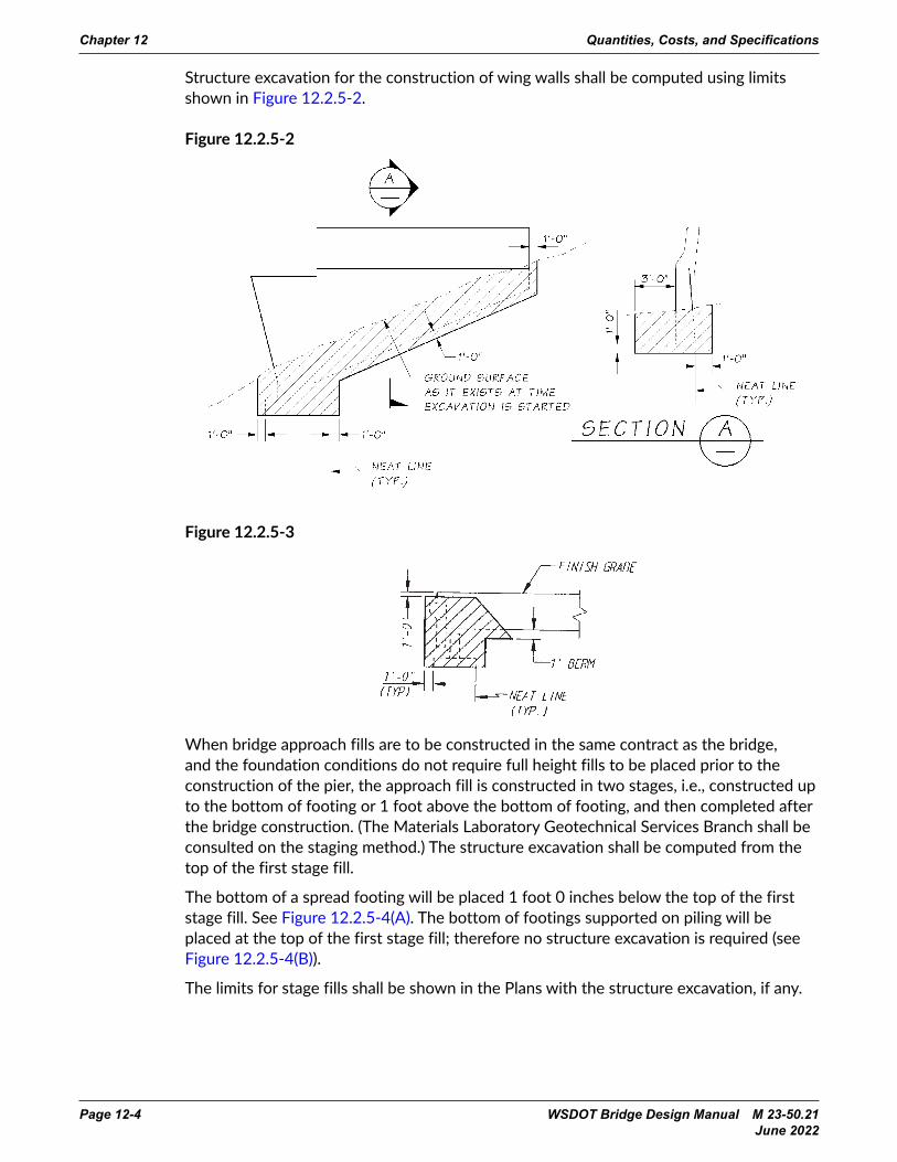
Structure excavation for the construction of wing walls shall be computed using limits shown in Figure 12.2.5-2.
Figure 12.2.5-2 11.2-2 August 2002
BRIDGE DESIGN MANUALCriteria
Quantities Computation of Quantities
B. Final Quantities
Final quantities to be listed in the Special Provisions and Bid Proposal sheet are to be calculated tohave an accuracy of ±1 percent, including bar list.
11.2.5 Excavation
A. Structure Excavation, Class A
Excavation necessary for the construction of bridge piers and reinforced concrete retaining walls isclassified as Structure Excavation, Class A. Payment for such excavation is generally at the unitcontract price per cubic yard. The quantity of excavation to be paid for is measured as outlined inSection 209.4 of the Standard Specifications. Computation of the quantity shall follow the sameprovisions. Designers shall familiarize themselves with this section of the Standard Specifications.Any limits for structure excavation not conforming to the limits specified in the StandardSpecifications shall be shown in the Plans.
Structure excavation for footings and seals shall be computed using a horizontal limit of 1 foot0 inches outside and parallel to the neat lines of the footing or seal or as shown in the Plans. Theupper limit shall be the ground surface or stream bed as it exists at the time the excavation is started.See Figure 11.2.6-1(A), (B), and (C).
Figure 11.2.6-1
August 2002 11.2-3
BRIDGE DESIGN MANUALCriteria
Quantities Computation of Quantities
Structure excavation for the construction of wing walls shall be computed using limits shown inFigure 11.2.6-2.
Figure 11.2.6-2
Figure 11.2.6-3
Figure 12.2.5-3
11.2-2 August 2002
BRIDGE DESIGN MANUALCriteria
Quantities Computation of Quantities
B. Final Quantities
Final quantities to be listed in the Special Provisions and Bid Proposal sheet are to be calculated tohave an accuracy of ±1 percent, including bar list.
11.2.5 Excavation
A. Structure Excavation, Class A
Excavation necessary for the construction of bridge piers and reinforced concrete retaining walls isclassified as Structure Excavation, Class A. Payment for such excavation is generally at the unitcontract price per cubic yard. The quantity of excavation to be paid for is measured as outlined inSection 209.4 of the Standard Specifications. Computation of the quantity shall follow the sameprovisions. Designers shall familiarize themselves with this section of the Standard Specifications.Any limits for structure excavation not conforming to the limits specified in the StandardSpecifications shall be shown in the Plans.
Structure excavation for footings and seals shall be computed using a horizontal limit of 1 foot0 inches outside and parallel to the neat lines of the footing or seal or as shown in the Plans. Theupper limit shall be the ground surface or stream bed as it exists at the time the excavation is started.See Figure 11.2.6-1(A), (B), and (C).
Figure 11.2.6-1
August 2002 11.2-3
BRIDGE DESIGN MANUALCriteria
Quantities Computation of Quantities
Structure excavation for the construction of wing walls shall be computed using limits shown inFigure 11.2.6-2.
Figure 11.2.6-2
Figure 11.2.6-3When bridge approach fills are to be constructed in the same contract as the bridge, and the foundation conditions do not require full height fills to be placed prior to the construction of the pier, the approach fill is constructed in two stages, i.e., constructed up to the bottom of footing or 1 foot above the bottom of footing, and then completed after the bridge construction. (The Materials Laboratory Geotechnical Services Branch shall be consulted on the staging method.) The structure excavation shall be computed from the top of the first stage fill.
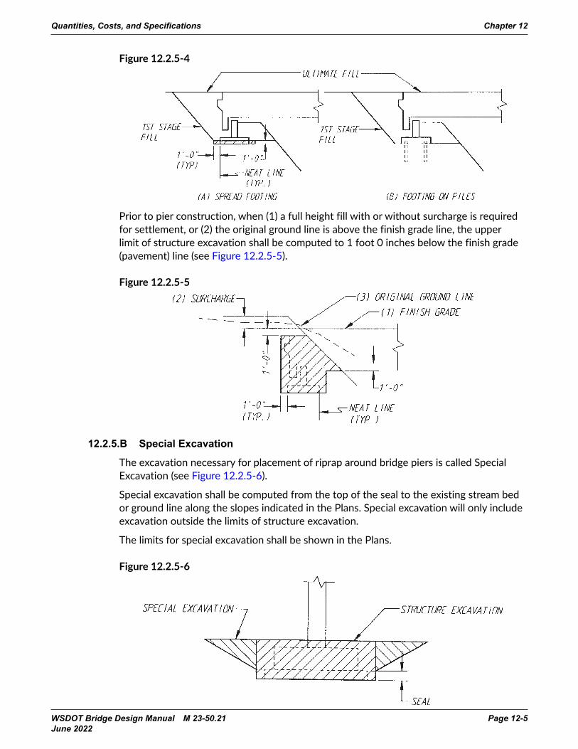
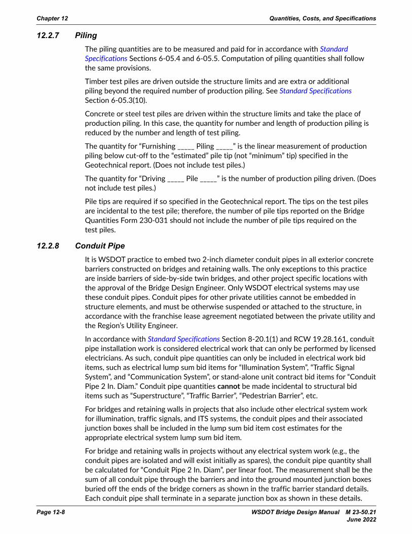
The bottom of a spread footing will be placed 1 foot 0 inches below the top of the first stage fill. See Figure 12.2.5-4(A). The bottom of footings supported on piling will be placed at the top of the first stage fill; therefore no structure excavation is required (see Figure 12.2.5-4(B)).
The limits for stage fills shall be shown in the Plans with the structure excavation, if any.
Quantities, Costs, and Specifications Chapter 12
WSDOT Bridge Design Manual M 23-50.21 Page 12-5 June 2022
Figure 12.2.5-4
11.2-4 August 2002
BRIDGE DESIGN MANUALCriteria
Quantities Computation of Quantities
When bridge approach fills are to be constructed in the same contract as the bridge and the foundationconditions do not require full height fills to be placed prior to the construction of the pier, the approach fillis constructed in two stages, i.e., constructed up to the bottom of footing or 1 foot above the bottom offooting and then completed after the bridge construction. (The Materials Laboratory shall be consulted onthe staging method.) The structure excavation shall be computed from the top of the first stage fill.
The bottom of a spread footing will be placed 1 foot 0 inches below the top of the first stage fill. SeeFigure 11.2.6-4(A). The bottom of footings supported on piling will be placed at the top of the first stagefill; therefore, no structure excavation is required (see Figure 11.2.6-4(B)).
The limits for stage fills shall be shown in the Plans with the structure excavation, if any.
Figure 11.2.6-4
Prior to pier construction, when (1) a full height fill with or without surcharge is required for settlement,or (2) the original ground line is above the finish grade line, structure excavation shall be computed to1 foot 0 inches below the finish grade (pavement) line (see Figure 11.2.6-5).
Figure 11.2.6-5
Prior to pier construction, when (1) a full height fill with or without surcharge is required for settlement, or (2) the original ground line is above the finish grade line, the upper limit of structure excavation shall be computed to 1 foot 0 inches below the finish grade (pavement) line (see Figure 12.2.5-5).
Figure 12.2.5-5
11.2-4 August 2002
BRIDGE DESIGN MANUALCriteria
Quantities Computation of Quantities
When bridge approach fills are to be constructed in the same contract as the bridge and the foundationconditions do not require full height fills to be placed prior to the construction of the pier, the approach fillis constructed in two stages, i.e., constructed up to the bottom of footing or 1 foot above the bottom offooting and then completed after the bridge construction. (The Materials Laboratory shall be consulted onthe staging method.) The structure excavation shall be computed from the top of the first stage fill.
The bottom of a spread footing will be placed 1 foot 0 inches below the top of the first stage fill. SeeFigure 11.2.6-4(A). The bottom of footings supported on piling will be placed at the top of the first stagefill; therefore, no structure excavation is required (see Figure 11.2.6-4(B)).
The limits for stage fills shall be shown in the Plans with the structure excavation, if any.
Figure 11.2.6-4
Prior to pier construction, when (1) a full height fill with or without surcharge is required for settlement,or (2) the original ground line is above the finish grade line, structure excavation shall be computed to1 foot 0 inches below the finish grade (pavement) line (see Figure 11.2.6-5).
Figure 11.2.6-5
11.2-4 August 2002
BRIDGE DESIGN MANUALCriteria
Quantities Computation of Quantities
When bridge approach fills are to be constructed in the same contract as the bridge and the foundationconditions do not require full height fills to be placed prior to the construction of the pier, the approach fillis constructed in two stages, i.e., constructed up to the bottom of footing or 1 foot above the bottom offooting and then completed after the bridge construction. (The Materials Laboratory shall be consulted onthe staging method.) The structure excavation shall be computed from the top of the first stage fill.
The bottom of a spread footing will be placed 1 foot 0 inches below the top of the first stage fill. SeeFigure 11.2.6-4(A). The bottom of footings supported on piling will be placed at the top of the first stagefill; therefore, no structure excavation is required (see Figure 11.2.6-4(B)).
The limits for stage fills shall be shown in the Plans with the structure excavation, if any.
Figure 11.2.6-4
Prior to pier construction, when (1) a full height fill with or without surcharge is required for settlement,or (2) the original ground line is above the finish grade line, structure excavation shall be computed to1 foot 0 inches below the finish grade (pavement) line (see Figure 11.2.6-5).
Figure 11.2.6-512.2.5.B Special Excavation
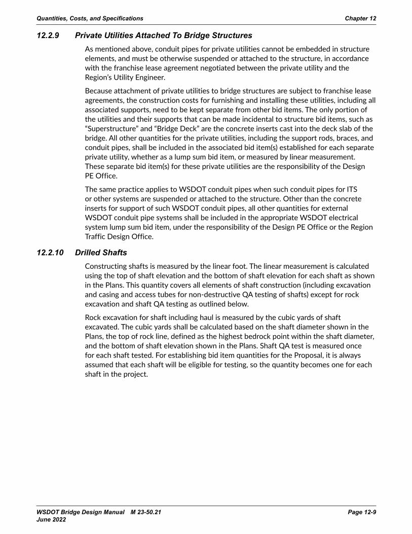
The excavation necessary for placement of riprap around bridge piers is called Special Excavation (see Figure 12.2.5-6).
Special excavation shall be computed from the top of the seal to the existing stream bed or ground line along the slopes indicated in the Plans. Special excavation will only include excavation outside the limits of structure excavation.
The limits for special excavation shall be shown in the Plans.
Figure 12.2.5-6
August 2002 11.2-5
BRIDGE DESIGN MANUALCriteria
Quantities Computation of Quantities
B. Special Excavation
The excavation necessary for placement of riprap around bridge piers is called Special Excavation(see Figure 11.2.6-6).
Special excavation shall be computed from the top of the seal to the existing stream bed or groundline along the slopes indicated in the Plans. Special excavation will only include excavation outsidethe limits of structure excavation.
The limits for special excavation shall be shown in the Plans.
Figure 11.2.6-6
C. Shaft Excavation
Excavation necessary for the construction of shaft foundations is generally measured by the cubicyard and paid for at the unit contract price per cubic yard for “Soil Excavation for Shaft IncludingHaul.”
The usual limits for computing shaft excavation shall be the neat lines of the shaft diameter and fromthe bottom elevation of the shaft as shown in the Plans to the ground surface as it exists at the time ofshaft excavation.
The methods of measurement and payment and the limits for shaft excavation shall be specified in theSpecial Provisions.
11.2.6 Shoring or Extra Excavation, Class A
All excavation in the dry which requires workmen to enter the excavated area and which has a depth of4 feet or more is required to be shored, unless the earth face is excavated at its angle of repose (ExtraExcavation).
All excavation which is 15 feet or less from the edge of a traveled pavement is also required to be shored.All excavation adjacent to railroad tracks shall also be shored.
Cofferdams are required for all underwater excavation or excavation affected by ground water.
Shoring, cofferdams, or caissons or extra excavation required for the construction of bridge footings andreinforced concrete retaining walls constructed in the wet or dry is classified as Shoring or ExtraExcavation, Class A.

Chapter 12 Quantities, Costs, and Specifications
Page 12-6 WSDOT Bridge Design Manual M 23-50.21 June 2022
12.2.6 Shoring or Extra Excavation, Class AShoring, cofferdams or caissons, or extra excavation required for construction of bridge footings and reinforced concrete retaining walls constructed in the wet or dry is classified as Shoring or Extra Excavation, Class A. See Standard Specifications Section 2-09.3(3).
Structural shoring (for dry excavation) or cofferdams (for wet excavation) is required for all excavations near completed structures (foundations of bridges, walls, or buildings), near underground utilities, near railroad tracks, and near pavement. All other excavation four feet or more in depth shall be either shored with structural shoring or cofferdams, or shall meet the open-pit excavation requirements as specified in Standard Specifications Section 2-09.3(3)B.
For the purpose of estimating the cost for shoring or extra excavation, Class A, it is necessary to compute the peripheral area of an assumed sheet pile enclosure of the excavated area.
While payment for Shoring or Extra Excavation, Class A, is made at a lump sum contract price, the costs are a function of the overall height of excavation. In general, each side of the excavation for each pier shall be categorized into an average overall height range as shown on WSDOT Form 230-031 (i.e., less than 6 feet, 6 to 10 feet, 10 to 20 feet, or greater than 20 feet), the area for the side computed using the appropriate width times the average overall height, the overall area for the side shall be entered in the category that matches the side’s average overall height. These calculations are required for each pier of the bridge as applicable. See accompanying Figure 12.2.6-1 and sample calculation.
For excavation in the dry, the peripheral area shall be the perimeter of the horizontal limits of structure excavation times the height from the bottom of the footing to the ground surface at the time of excavation.
For excavation in water, the peripheral area shall be the perimeter of the horizontal limits of structure excavation times the height from the bottom of the seal to 2 feet above the seal vent elevation.
For shaft-type excavations, it is not normally necessary to compute the area for shoring because the shoring is usually accommodated by the work items for permanent casing, temporary casing, and casing shoring.

Quantities, Costs, and Specifications Chapter 12
WSDOT Bridge Design Manual M 23-50.21 Page 12-7 June 2022
Figure 12.2.6-1
11.2-6 August 2002
BRIDGE DESIGN MANUALCriteria
Quantities Computation of Quantities
For the purpose of estimating the cost for cofferdams or for shoring or extra excavation, Class A, it isnecessary to compute the peripheral area of an assumed sheet pile enclosure of the excavated area.
While payment for Shoring or Extra Excavation, Class A, is made at a lump sum contract price, the costsare a function of overall height of excavation. In general, each side of the excavation for each pier shall becategorized into an average overall height range as shown on Form 230-031 (i.e., less than 6 feet, 6 to 10feet, 10 to 20 feet, or greater than 20 feet), the area for the side computed using the appropriate widthtimes the average overall height, the overall area for the side shall be entered in the category that matchesthe side’s average overall height. These calculations are required for each pier of the bridge as applicable.See accompanying Figure 11.2.6-7 and sample calculation.
For excavation in the dry, the peripheral area shall be the perimeter of the horizontal limits of structureexcavation times the height from the bottom of the footing to the ground surface at the time of excavation.
For excavation in water, the peripheral area shall be the perimeter of the horizontal limits of structureexcavation times the height from the bottom of the seal to 2 feet above the seal vent elevation.
For shaft-type foundations, it is not necessary to compute the area for shoring because the cost for shoringis normally included in the contract price for shaft excavation.
Figure 11.2.6-7Sample Calculation:
For this pier (Figure 12.2.6-1):
Side A: average height = (4 + 6)/2 = 5 feet width = 15 feet area = 5 × 15 = 75 square feet
Side B: average height = (6 + 15)/2 = 10.5 feet width = 20 feet area = 10.5 × 20 = 210 square feet
Side C: average height = (10 + 15)/2 = 12.5 feet width = 15 feet area = 12.5 × 15 = 187.5 square feet
Side D: average height = (4 + 10)/2 = 7 feet width = 20 feet area = 7 × 20 = 140 square feet
For this example
Height Category Arealess than 6 feet 75 square feet6 feet to 10 feet 140 square feet
10 feet to 20 feet 210 + 188 = 398 square feetgreater than 20 feet N.A.
These numbers would be entered on WSDOT Form 230-031 as follows:
Standard Item Number 4012
Item Use Standard Item
Item Description Shoring or Extra Excavation, Class A Dry:
Average Overall HeightQuant. (Enter Total
for Bridge Here)Unit of
Meas. L.S.Pier 6 ft 6 ft to 10 ft 10 ft* to 20 ft 20 ft S.F.
Example 75 S.F. 140 S.F. 398 (11.5*) S.F. — S.F.S.F. S.F. S.F. S.F.S.F. S.F. S.F. S.F.S.F. S.F. S.F. S.F.
* Indicate Average Height
Chapter 12 Quantities, Costs, and Specifications
Page 12-8 WSDOT Bridge Design Manual M 23-50.21 June 2022
12.2.7 PilingThe piling quantities are to be measured and paid for in accordance with Standard Specifications Sections 6-05.4 and 6-05.5. Computation of piling quantities shall follow the same provisions.
Timber test piles are driven outside the structure limits and are extra or additional piling beyond the required number of production piling. See Standard Specifications Section 6-05.3(10).
Concrete or steel test piles are driven within the structure limits and take the place of production piling. In this case, the quantity for number and length of production piling is reduced by the number and length of test piling.
The quantity for “Furnishing _____ Piling _____” is the linear measurement of production piling below cut-off to the “estimated” pile tip (not “minimum” tip) specified in the Geotechnical report. (Does not include test piles.)
The quantity for “Driving _____ Pile _____” is the number of production piling driven. (Does not include test piles.)
Pile tips are required if so specified in the Geotechnical report. The tips on the test piles are incidental to the test pile; therefore, the number of pile tips reported on the Bridge Quantities Form 230-031 should not include the number of pile tips required on the test piles.
12.2.8 Conduit PipeIt is WSDOT practice to embed two 2-inch diameter conduit pipes in all exterior concrete barriers constructed on bridges and retaining walls. The only exceptions to this practice are inside barriers of side-by-side twin bridges, and other project specific locations with the approval of the Bridge Design Engineer. Only WSDOT electrical systems may use these conduit pipes. Conduit pipes for other private utilities cannot be embedded in structure elements, and must be otherwise suspended or attached to the structure, in accordance with the franchise lease agreement negotiated between the private utility and the Region’s Utility Engineer.
In accordance with Standard Specifications Section 8-20.1(1) and RCW 19.28.161, conduit pipe installation work is considered electrical work that can only be performed by licensed electricians. As such, conduit pipe quantities can only be included in electrical work bid items, such as electrical lump sum bid items for “Illumination System”, “Traffic Signal System”, and “Communication System”, or stand-alone unit contract bid items for “Conduit Pipe 2 In. Diam.” Conduit pipe quantities cannot be made incidental to structural bid items such as “Superstructure”, “Traffic Barrier”, “Pedestrian Barrier”, etc.
For bridges and retaining walls in projects that also include other electrical system work for illumination, traffic signals, and ITS systems, the conduit pipes and their associated junction boxes shall be included in the lump sum bid item cost estimates for the appropriate electrical system lump sum bid item.
For bridge and retaining walls in projects without any electrical system work (e.g., the conduit pipes are isolated and will exist initially as spares), the conduit pipe quantity shall be calculated for “Conduit Pipe 2 In. Diam”, per linear foot. The measurement shall be the sum of all conduit pipe through the barriers and into the ground mounted junction boxes buried off the ends of the bridge corners as shown in the traffic barrier standard details. Each conduit pipe shall terminate in a separate junction box as shown in these details.
Quantities, Costs, and Specifications Chapter 12
WSDOT Bridge Design Manual M 23-50.21 Page 12-9 June 2022
12.2.9 Private Utilities Attached To Bridge StructuresAs mentioned above, conduit pipes for private utilities cannot be embedded in structure elements, and must be otherwise suspended or attached to the structure, in accordance with the franchise lease agreement negotiated between the private utility and the Region’s Utility Engineer.
Because attachment of private utilities to bridge structures are subject to franchise lease agreements, the construction costs for furnishing and installing these utilities, including all associated supports, need to be kept separate from other bid items. The only portion of the utilities and their supports that can be made incidental to structure bid items, such as “Superstructure” and “Bridge Deck” are the concrete inserts cast into the deck slab of the bridge. All other quantities for the private utilities, including the support rods, braces, and conduit pipes, shall be included in the associated bid item(s) established for each separate private utility, whether as a lump sum bid item, or measured by linear measurement. These separate bid item(s) for these private utilities are the responsibility of the Design PE Office.
The same practice applies to WSDOT conduit pipes when such conduit pipes for ITS or other systems are suspended or attached to the structure. Other than the concrete inserts for support of such WSDOT conduit pipes, all other quantities for external WSDOT conduit pipe systems shall be included in the appropriate WSDOT electrical system lump sum bid item, under the responsibility of the Design PE Office or the Region Traffic Design Office.
12.2.10 Drilled ShaftsConstructing shafts is measured by the linear foot. The linear measurement is calculated using the top of shaft elevation and the bottom of shaft elevation for each shaft as shown in the Plans. This quantity covers all elements of shaft construction (including excavation and casing and access tubes for non-destructive QA testing of shafts) except for rock excavation and shaft QA testing as outlined below.
Rock excavation for shaft including haul is measured by the cubic yards of shaft excavated. The cubic yards shall be calculated based on the shaft diameter shown in the Plans, the top of rock line, defined as the highest bedrock point within the shaft diameter, and the bottom of shaft elevation shown in the Plans. Shaft QA test is measured once for each shaft tested. For establishing bid item quantities for the Proposal, it is always assumed that each shaft will be eligible for testing, so the quantity becomes one for each shaft in the project.
Chapter 12 Quantities, Costs, and Specifications
Page 12-10 WSDOT Bridge Design Manual M 23-50.21 June 2022
12.3 Construction Costs12.3.1 Introduction
The construction costs itemized in Appendix 12.3-A1, 12.3-A2, 12.3-A3, and 12.3-A4 are to aid the user in estimating the cost of bridge and structure projects. The costs are based on historical data maintained by the Bridge and Structures Office and retrieved from recent WSDOT Contracts.
Requests for cost estimates from WSDOT Region Offices and other Local Agency offices should be submitted in writing (hard copy or email) to the Bridge Project Support Unit, and a written or email response will be returned within a reasonable time based on the schedule needs of the requesting office. Scoping or prospectus type cost estimates, and other cost estimates based upon deck area cost history and other readily available geotechnical information and project parameters can be prepared relatively quickly. Estimates requiring input from the Bridge Design Unit, either for preparation of preliminary quantities or other preliminary structural analysis will take longer to prepare.
Telephone requests for cost estimates from WSDOT Region Offices and other Local Agency Offices shall be referred to the Bridge Project Support Unit for response.
All cost estimates prepared by the Bridge and Structures Office should have the concurrence of the Bridge Project Support Engineer.
12.3.2 Factors Affecting Costs
12.3.2.A Type of Structure
Many factors, as outlined in Section 2.2.3, must be considered in the selection of the type, size, and location of a bridge or wall.
Common structures with conventional details will be within the low end and mid-range of costs. Unique or complex structures will be within the high end.
12.3.2.B Location of Project Site
Projects in remote areas or with difficult access will generally be within or above the high end of the cost range.
12.3.2.C Size of Project Contract
Small projects tend to be within the high end of the cost range while large projects tend to be within the low end of the cost range.
12.3.2.D Foundation Requirements
Foundation requirements greatly affect costs. Water crossings requiring pier construction within the waterway are generally very expensive. Scour requirements can push the costs even higher. The earlier foundation information can be made available the more accurate the cost estimate will be. The Bridge Project Support Unit should be made aware of unusual foundation requirements or changes to foundation type as soon as possible for updating of the estimate.
12.3.2.E Sequencing of Project
Projects with stage construction, detours, temporary construction, etc., will be more expensive.

Quantities, Costs, and Specifications Chapter 12
WSDOT Bridge Design Manual M 23-50.21 Page 12-11 June 2022
12.3.3 Development of Cost EstimatesEstimates prepared by the Bridge and Structures Office shall include 10 percent mobilization but not sales tax, engineering, construction contingencies, or inflation.
12.3.3.A Types
12.3.3.A.1 Prospectus and Project Summary Estimates
Conceptual cost estimates are prepared when little information about the project is available. Use the construction costs in Appendix A, assuming the worst case conditions, unless actual conditions are known. An example of a worst case condition is deep foundation substructure (pile supported footings or shaft foundations). In remote areas, or for small projects, use the high end of the cost range. Use mid-range costs for usual conditions.
To cover unforeseen project modifications, add a 20 percent estimate contingency to a prospectus estimate and a 10 percent estimate contingency to a project summary estimate. These contingencies can be adjusted depending on the preliminary information available.
12.3.3.A.2 Preliminary Design Estimates
Preliminary design estimates are prepared during the preliminary design stage when the type and size of bridge is known. Limited foundation information is sometimes available at this stage. The construction costs in Appendix A shall be used with an appropriate inflation factor, assuming the worst case conditions, unless foundation conditions are known, along with a minimum of 10 percent contingency to cover scope creep.
12.3.3.A.3 Estimate Updates During Design
During the design period, the designer should keep the Bridge Project Support Unit informed of significant changes to the design that might affect the cost. Examples of significant changes are: deeper than expected footing and seals, use of deep foundations (shafts or piles) when none were previously expected, change of substructure types, and changes to superstructure. This is a critical element in the project budgeting process.
12.3.3.A.4 Contract Estimates
The contract estimate is prepared by the Bridge Project Support Unit after the Plans and Final Quantities have been submitted to the Bridge Project Support Unit for preparation of the final Bridge PS&E. The contract estimate is prepared using the quantities furnished by the Bridge Design Unit, unit bid prices from Appendix A, other historical data, and the judgment of the engineer preparing the estimate. Unique, one-of-a-kind projects require special consideration and should include an appropriate construction cost contingency.

Chapter 12 Quantities, Costs, and Specifications
Page 12-12 WSDOT Bridge Design Manual M 23-50.21 June 2022
12.3.3.B Responsibilities
12.3.3.B.1 Bridge Project Support Unit
The Bridge Project Support Unit is responsible for preparing the prospectus, project summary, preliminary, and final contract estimates and updating the preliminary estimate as needed during the design phase of the project.
The Bridge Project Support Unit assists the WSDOT Region Offices and other outside Local Agency Offices, such as counties and cities, to prepare prospectus and project summary estimates when requested in writing.
12.3.3.B.2 Designer
The designer is responsible for providing preliminary quantities and final quantities to the Bridge Project Support Unit to aid in the updating of preliminary estimates and the preparation of contract estimates.
12.3.3.C Documentation
Whenever a cost estimate is prepared by the Bridge and Structures Office for an outside office, a Cost Estimate Summary sheet (Appendix 12.3-B1) shall be filled out by the Engineer preparing the estimate. The Cost Estimate Summary shall be maintained in the Job File. During the design stage, the summary sheet shall be maintained by the Bridge Design Unit. At a minimum, the Cost Estimate Summary should list the initial and all subsequent cost estimates for each Preliminary Plan distribution made. It is the Design Unit Manager’s responsibility to ensure the summary sheet is up to date when the job file is submitted to the Bridge Project Support Unit for preparation of the Bridge PS&E.
12.3.3.D Cost Data
12.3.3.D.1 General
The Bridge costs summarized in Appendix A represent common highway, railroad, and water crossings. Consult the Bridge Project Support Unit for structures spanning across large rivers or canyons and other structures requiring high clearances or special design and construction features.
The square foot costs are useful in the conceptual and preliminary design stages when details or quantities are not available. The various factors affecting costs as outlined in Section 12.3.2 must be considered in selecting the square foot cost for a particular project. As a general rule, projects including none or few of the high-cost factors will be close to the mid-range of the cost figures. Projects including many of the high-cost factors will be on the high side. The user must exercise good judgment to determine reasonable costs. During the preliminary stage, it is better to be on the prudently conservative side for budgeting purposes.
12.3.3.D.2 Deck or Wall Face Area
The area to be used for cost estimates based upon deck or wall face area shall be computed as follows:

Quantities, Costs, and Specifications Chapter 12
WSDOT Bridge Design Manual M 23-50.21 Page 12-13 June 2022
12.3.3.D.3 Bridge Widenings and New Bridges
The deck area of bridges is based on the actual width of the new portion of the bridge deck constructed (measured to the outside edge of the bridge deck) times the length, measured from end of wingwall to end of wingwall, end of curtain wall to end of curtain wall, or back to back of pavement seat if there are no wingwalls or curtain walls. Wingwalls are defined as walls without footings which are cast monolithically with the bridge abutment wall and may extend past the abutment footing. Curtain walls are defined as walls that are cast monolithically with the bridge abutment wall and footing and only extend to the edge of footing.
12.3.3.D.4 Bridge Rail Replacement
The bridge rail and curb removal is based on the total length of the rail and curb removed.
12.3.3.D.5 Bridge Lengths With Unequal Wingwalls
If a bridge has wingwalls or curtain walls of unequal length on opposite sides at a bridge end of wingwalls or curtain walls on one side of a pier only, the length used in computing the square foot area is the average length of the walls. If the wingwalls are not parallel to the centerline of the bridge, the measurement is taken from a projected line from the end of the wingwall normal to the centerline of the roadway.
12.3.3.D.6 Retaining Walls
If retaining walls (walls that are not monolithic with the abutment) extend from the end of the bridge, the cost of these walls is computed separately. The area of the wall is based on the overall length of the wall, and the height from the top of footing to the top of the wall.
Chapter 12 Quantities, Costs, and Specifications
Page 12-14 WSDOT Bridge Design Manual M 23-50.21 June 2022
12.4 Construction Specifications and Estimates12.4.1 General
The Bridge Project Support Unit prepares the specifications and estimates (S&E) for all structural projects designed or reviewed by the Bridge and Structures Office. The preparation includes distributing review sets, reviewing the job file, plans, PS&E check list, “Not Included in Bridge Quantities List,” and Geotechnical report; preparing the cost estimates, specifications, and working day schedules; and submitting the PS&E package to the Region.
12.4.2 Definitions
12.4.2.A Standard Specifications
The Standard Specifications is published annually by the WSDOT Engineering Publications Office, is maintained by the WSDOT Construction Office, and is used as the governing construction specification for all WSDOT construction projects.
12.4.2.B Mandatory General Special Provisions
Mandatory General Special Provisions are revisions to specific sections of the Standard Specifications, which are enacted during the year period that a specific edition of the Standard Specifications is in force. Mandatory General Special Provisions are published throughout the year as immediate needs for specification additions and revisions arise.
12.4.2.C Special Provisions
Special Provisions are supplemental specifications and modifications to the Standard Specifications, which apply to a specific project.
12.4.2.D Addendum
A written or graphic document, issued to all bidders and identified as an addendum prior to bid opening, which modifies or supplements the bid documents and becomes a part of the contract.
12.4.2.E AD Copy
The AD copy is the contract document advertised to prospective bidders. The AD Copy may include, but not be limited to, the following as component parts: Bid Proposal Form, Special Provisions, Amendments, Plans, and Appendices including test hole boring logs, and environmental permit conditions.
12.4.2.F As defined in Standard Specifications Section 1-02.4
The order of precedence of AD Copy components is as follows: Addenda, Bid Proposal Form, Special Provisions (including Mandatory General Special Provisions, Plans, Standard Specifications, and Standard Plans.
Quantities, Costs, and Specifications Chapter 12
WSDOT Bridge Design Manual M 23-50.21 Page 12-15 June 2022
12.4.3 General Bridge S&E Process
12.4.3.A Typical Reviews and Milestone Dates
The Ad Date, as established by the Region, is the anchor for all project schedule dates.
The Scope Of Work Agreement (SOW) is a document negotiated between the Design PE Office and the Bridge and Structures Office establishing the deliverables (design submittals) to be produced and the due dates for the various deliverable review milestones for the specific project.
The Structural Submittal Expectations Matrix at www.wsdot.wa.gov/publications/fulltext/ProjectMgmt/DEM/Bridge.pdf outlines the expected content of the design submittal deliverables at specific stages of design development.
When a Constructability Review is set by the SOW, the Bridge Design Unit or Bridge Consultant assigned to the project is responsible for providing the plan content specified by the design matrix, and providing the quantities based on preliminary foundation design sizes. The Bridge Project Support Unit is responsible for providing the cost estimate and a set of Special Provisions that includes all applicable General Special Provisions (GSPs). The GSPs with fill-ins need not have the fill-in text included at this time, and project specific Special Provisions need not be included at this time.
The Bridge Design Unit or Bridge Consultant shall coordinate with the Bridge Project Support Unit with enough lead time to allow completion of the cost estimate and Constructability Special Provisions in time for the Constructability Review submittal to the Region Design PEO.
For the PS&E Review Set turn-in, the Bridge Design Unit or Bridge Consultant assigned to the project shall provide completed plans and quantities to the Bridge Project Support Unit at least two-weeks in advance of the scheduled PS&E Review turn-in date. The Bridge Project Support Unit is responsible for developing a complete set of Special Provisions, with completed GSPs and project specific special provisions, and a complete cost estimate.
For hydraulic, mechanical, and electrical rehabilitation projects for movable bridges, the Bridge Preservation Office takes a lead role in managing the design process for the project.
12.4.3.B Constructability Review Set Distribution
The Bridge Specifications and Estimates Engineer assigned to the project distributes the Constructability Review set, consisting of PDFs of the Structure Plans, cost estimate, and assembled bridge special provision document (raw GSPs), and the Word document of the associated special provision runlist, to the following:• Design Project Engineer• Design PEO Team Leader• Design PEO Designer• Region Plans Office Reviewer
• Bridge Design Unit Supervisor• Bridge Design Unit Team Leader/
Designer
The Bridge Design Unit Team Leader/Designer and Bridge Specifications and Estimates Engineer for the project participate in the Constructability Review and coordinate to address review comments generated by the review.

Chapter 12 Quantities, Costs, and Specifications
Page 12-16 WSDOT Bridge Design Manual M 23-50.21 June 2022
12.4.3.C PS&E Review Set Distribution
The Bridge Specifications and Estimates Engineer assigned to the project distributes the PS&E Review set to the following:• Design Project Engineer• Design PEO Team Leader• Design PEO Designer• Region Plans Office Reviewer• Region Design Engineering Manager or equivalent• FHWA Washington Division Bridge Engineer• Materials Laboratory (Record of Materials and PS&E Distribution mailbox)• HQ Construction Office Bridge Engineer• Bridge Project Support Manager• Bridge Preservation Office (Review mailbox)• Bridge Design Unit Supervisor• Bridge Design Unit Team Leader/Designer• State Bridge Design Engineer• State Bridge and Structures Engineer• Bridge Scheduler
The content of the distribution set is defined by Section 12.4.9.A.
The Bridge Design Unit Team Leader/Designer and Bridge Specifications and Estimates Engineer for the project participate in the PS&E Review and coordinate to address review comments generated by the review.
12.4.4 Reviewing Bridge PlansThe Bridge Specifications and Estimates Engineer performs the following tasks after receiving the Structure Plans and associated quantities from the Bridge Design Unit or Bridge Consultant in advance of the PS&E Review set distribution:
12.4.4.A Job File
Review correspondence and emails in the job file for the items of work and other commitments which need to be included in the Bridge PS&E. Identify items that need special provisions and bid item references. Identify items that require additional research by, and information from, the bridge designer, Region designers, or others. Confirm that the job file fly leaf information has been completed by the designer (Form 221-076).
12.4.4.B PS&E Check List (Form 230-037 and Appendix 12.4-A1)
Review the form as completed by the bridge designer for identified needs for special materials, construction requirements, permits, etc., which may need Special Provisions such as:• Permits: United States Coast Guard• Agreements: utilities on bridge, etc.• Materials: high strength structural steel, high-strength concrete, polyester and
polymer concrete, carbon fiber wrap, high-load elastomeric bearing pads and other high capacity bridge bearings, etc.
Quantities, Costs, and Specifications Chapter 12
WSDOT Bridge Design Manual M 23-50.21 Page 12-17 June 2022
• Construction Requirements: temporary access, stage construction, construction over railroad, special welding and welding inspection requirements, and other special construction requirements
• Special Items: modified concrete overlay or special architectural, paint, and sealer treatments
• Proprietary Materials: identification of, and justification for use of, products and materials which are specified in the Structure Plans by specific manufacturer and model, instead of generic manufacture
12.4.4.C Summary of Quantities (Form 230-031 and Appendix 12.2-A1)
Verify that the Summary of Quantities is labeled as “Manager’s Bridge Quantities.” See Section 12.2.2. Quantities listed in this form are used to develop the Bridge Cost Estimate for the project.
12.4.4.D Plans
Review the plans for consistency with the special needs identified by the bridge designer in the PS&E check list form (subsection B above), use of standard notes and General Notes, completeness of title block information, and use of terminology consistent with the Standard Specifications, Standard Plans, and Standard Bid Items.
12.4.4.E Not Included in Bridge Quantities List (Form 230-038 and Appendix 12.1-A1)
Review the form completed by the bridge designer and compare with the Structure Plans for items shown in the Structure Plans that may be missing from the list. See Section 12.1.2.
12.4.4.F Geotechnical Report
Review the Geotechnical Report for the project to confirm that the foundation types, sizes, and elevations shown in the Bridge Plans are consistent with the recommendations specified in the Geotechnical Report. Obtain a copy of the final Geotechnical Report for the S&E file. Review the Geotechnical Report for construction consideration requirements which may need to be noted in the Special Provisions, such as shaft casing requirements, bridge embankment settlement periods, special excavation, etc. Compare the number of test holes and the locations shown in the layout sheets for all bridges against number and locations of test holes identified in the final Geotechnical Report.
12.4.5 Preparing the Bridge Cost Estimates
12.4.5.A General
From the quantities shown in the Summary of Quantities form submitted with the Structure Plans (whether for Constructability Review or PS&E Review), the Bridge Specifications and Estimates Engineer develops the Bridge Cost Estimate for the project. The Bridge Project Support Unit uses a standard spreadsheet format for Cost Estimates. This spreadsheet includes the tabulation of all bridge bid items, a breakdown for each lump sum item, and square foot cost of the structure.

Chapter 12 Quantities, Costs, and Specifications
Page 12-18 WSDOT Bridge Design Manual M 23-50.21 June 2022
12.4.5.B Procedure
Each quantity shown in the Summary of Quantities form is to be matched with an appropriate unit bid item or lump sum bid item. These can be Standard Bid Items from the Standard Bid Item Table, or project specific non-standard bid items.
Pricing for the bid items above can be based on the Construction Cost Estimating Aids listed in Appendices 12.3-A1, 12.3-A2, 12.3-A3, and 12.3-A4, bid tabulations from previous contracts, and the Unit Bid Analysis and Standard Item Table listing available through the WSDOT Contract Ad & Award Office web site. The Bridge Specifications and Estimates Engineer uses appropriate engineering judgment to make appropriate adjustments for inflation, site location, quantities involved, total of the work involved, etc.
All Standard Bid Items listed in the spreadsheet shall include the Standard Bid Item number assigned to that bid item. All non-standard bid items shall be identified by the appropriate pre-qualification code for the bid item work. The pre-qualification codes specified in the Standard Item Table should be reviewed to help establish the appropriate code for non-standard bid items. When in doubt, the general Bridge and Structures pre-qualification code of (B0) should be used.
All bridge cost estimates shall include mobilization, but do not include sales tax, engineering, contingencies or inflation.
12.4.6 Preparing the Bridge Specifications
12.4.6.A General
There are two categories of Special Provisions:
1. General Special Provisions (GSP’s) are supplemental specifications which are standardized and approved for Statewide use, and maintained by the WSDOT Construction Office. GSP’s are formatted to supplement specific Standard Specifications Sections. GSP’s are identified by their publication and effective date in parenthesis immediately preceding the GSP text.
2. Project Specific Special Provisions include all supplemental specifications which are not GSP’s. Project Specific Special Provisions, as the name implies, are intended for project specific use, whether one time or infrequent. The vast majority of Project Specific Special Provisions are formatted to supplement specific Standard Specifications Sections. However, in rare cases, they can be formatted as “stand-alone” following the “Description/Materials/Construction Requirements/Measurement/Payment format. Project Specific Special Provisions are identified by six asterisks in parenthesis immediately preceding the text or heading. A Project Specific Special Provision that sees frequent use can be standardized and elevated to GSP status.
12.4.6.B Procedure
Based on review of the Structure Plans and the PS&E Check List, the Bridge Specifications and Estimates Engineer determines the items of work which are not already covered by the Standard Specifications and for which supplemental specifications are needed. Based on this determination, and review of the current list of GSP’s, a Bridge Special Provision runlist is prepared, listing the multi-character code of the applicable GSP documents needed for the project. GSP documents are listed in the WSDOT Construction Office web site.

Quantities, Costs, and Specifications Chapter 12
WSDOT Bridge Design Manual M 23-50.21 Page 12-19 June 2022
These documents are listed following the section order of the Standard Specifications. Fill-in blanks for GSP’s requiring project specific information can be completed at this time.
When the Standard Specifications and GSP’s are insufficient to cover project specific requirements, Project Specific Special Provisions are developed, and added by name at the appropriate location in the runlist.
See the Plans Preparation Manual Division 6 for further discussion and example flow charts.
When the Bridge Special Provision file is complete with all Special Provisions needed to accompany the Structure Plans, the Bridge Specifications and Estimates Engineer compiles a single space document of the Bridge Special Provision file for use in the Bridge PS&E distribution.
12.4.7 Preparing the Bridge Working Day Schedule
12.4.7.A General
The Bridge Specifications and Estimates Engineer calculates the number of the working days necessary to construct the bridge portion of the contract, based on the quantities shown in the Summary of Quantities form submitted with the Bridge Plans, and enters the time in the special provision “Time for Completion.” The working days are defined in the Standard Specifications Section 1-08.5.
12.4.7.B Procedure
The first task of estimating the number of working days is to list all the construction activities involved in the project. These include all actual construction activities such as excavation, forming, concrete placement, and curing; and the non-construction activities such as mobilization, material and shop plan approval. Special conditions such as staging, limited access near wetlands, limited construction windows for work in rivers and streams, limited working hours due to traffic and noise restrictions, require additional time.
The second task is to assign the number of working days to each construction activity above (see Appendix 12.4-A2). The “Construction Time Rate” table can be used as a guide to estimate construction time required. This table shows the average rate of output for a single shift, work day only. Adjustment to the rates of this table should be made based on project size, type of work involved, location of the project, etc. In general, larger project will have higher production rates than smaller projects, new construction will have higher production rates than widening, and unstaged work will have higher production rates than stages work.
The last step is to arrange construction activities, with corresponding working days, into a construction schedule on a bar chart, either by hand on the Construction Working Day Schedule Form 230-041 (see Appendix 12.4-B1) or by computer using a scheduling program. List the activities in a logical construction sequence, starting from the substructure to the superstructure. Items shall overlap where practical and the critical path shall be identified.
Chapter 12 Quantities, Costs, and Specifications
Page 12-20 WSDOT Bridge Design Manual M 23-50.21 June 2022
12.4.8 Reviewing Projects Prepared by Consultants
12.4.8.A General
Consultants preparing Structure Plans for WSDOT projects submit their Plans and quantities to the Bridge and Structures Office before the scheduled Bridge PS&E turn-in date, and with all associated information (files, forms, lists, and reports), as specified in Sections 12.4.3 and 12.4.4.
The package shall be in the same format as those prepared by the Bridge and Structures Office.
12.4.8.B Procedure
The Bridge Specifications and Estimates Engineer reviews the consultant’s Structure Plans following the process as specified in Sections 12.4.3 and 12.4.4. The review comments of the Bridge Specifications and Estimates Engineer are combined with review comments from the Bridge Design Unit assigned to review the project, and returned to the consultant in a timely manner through the Bridge Consultant Liaison Engineer, allowing the consultant to meet the scheduled turn-in date for the Bridge PS&E. After the consultant addresses all review comments and resubmits the package as 100 percent complete, the Bridge Specifications and Estimates Engineer compiles the Bridge PS&E package (See Section 12.4.9).
Except for hydraulic, mechanical, and electrical rehabilitation projects for movable bridges, and other unique bridge projects where specifically approved by the Bridge Project Support Engineer, all Bridge Special Provisions shall be prepared by the Bridge Project Support Unit. The Bridge Cost Estimate and working day schedule should be prepared by the Bridge Specifications and Estimates Engineer with assistance from the consultant as appropriate.
12.4.9 Submitting the PS&E Package
12.4.9.A General
The PS&E package includes:
1. PDF of Bridge Construction Cost Estimate for each separate structure
2. PDF of Cost Estimate Summary for each separate structure (see Appendix 12.3-B1)
3. PDF of Not Included in Bridge Quantity List
4. PDF of Construction Working Day Schedule
5. PDF of compiled Bridge Special Provision document with runlist
6. Word document of individual project specific Bridge Special Provisions and GSPs with fill-ins, and Word document of the associated runlist
7. PDF of the Structure Plan Set for all Structures
The Bridge PS&E is distributed to those identified in Section 12.4.3.B.
Quantities, Costs, and Specifications Chapter 12
WSDOT Bridge Design Manual M 23-50.21 Page 12-21 June 2022
12.4.10 PS&E Review Period and Turn-in for AD Copy
12.4.10.A Description
The PS&E Review Period between Bridge PS&E turn-in and Ad Date allows the Region to compile PS&E from their Design PE Office and all support groups into a Review PS&E set for distribution to appropriate parties for review and comment. The process ensures that all parts of the PS&E are compatible, complete, and constructible.
12.4.10.B Procedure
Each Region has its own specific process, but the general procedure is similar. The PS&E Review PS&E set is distributed to the Bridge Project Support Engineer or the Bridge Specifications and Estimates Engineer assigned to the project. The review is performed, and comments returned to the Region, by the due date specified in the distribution document. Review comments are returned to both the Region Plan Reviewer and the Region Design PE Team Leader/Designer assigned to the project.
Depending on the scope of the project, and the Region responsible for the project, there may be a meeting to discuss review comments. If such a meeting is held (generally about halfway through the PS&E review period), the Bridge Specifications and Estimates Engineer and others from the Bridge Design Unit responsible for the project, should consider attending if discussion of Bridge PS&E review comments is likely.
Shortly after the specified due date for review comments passes, Region comments on the Bridge PS&E should be received by the Bridge Specifications and Estimates Engineer and/or the bridge designer(s) in the Bridge Design Unit. These review comments on the Bridge PS&E are addressed before the final Bridge PS&E is turned-in for AD Copy printing. The Bridge Specifications and Estimates Engineer makes all necessary revisions to the Bridge Cost Estimate and Bridge Special Provisions, and notifies the appropriate contacts in the Region Design PE Office and the Region Plans Office when these changes are complete. This should be completed at least two weeks prior to the scheduled Ad Date.
After the Bridge Design Unit has completed all necessary revisions to the Structure Plans, the Structure Plans are signed and turned in to the Bridge Specifications and Estimates Engineer. Copies of these signed plans, together with the final set of bridge special provisions and the associated Certified Bridge Special Provisions and Cost Estimate document stamped and signed by the Bridge Specifications and Estimates Engineer for the project, comprise the Bridge AD-Ready PS&E.
This set of Bridge AD-Ready PS&E is the "Signed PS&E Set" deliverable of the Structural Submittal Expectations Matrix, and is sent to the Region (Region Plan Reviewer and Region Design PE Team Leader/Designer) for use in compiling the AD Copy PS&E. The Bridge Construction Support Engineer is also included in this email distribution as notice of the AD-Ready status of the project. This should be completed two weeks prior to the scheduled Ad Date.
Chapter 12 Quantities, Costs, and Specifications
Page 12-22 WSDOT Bridge Design Manual M 23-50.21 June 2022
12.5 AppendicesAppendix 12.1-A1 Not Included In Bridge Quantities List
Appendix 12.2-A1 Bridge Quantities
Appendix 12.3-A1 Structural Estimating Aids Construction Costs
Appendix 12.3-A2 Structural Estimating Aids Construction Costs
Appendix 12.3-A3 Structural Estimating Aids Construction Costs
Appendix 12.3-A4 Structural Estimating Aids Construction Costs
Appendix 12.3-B1 Cost Estimate Summary
Appendix 12.4-A1 Special Provisions Checklist
Appendix 12.4-A2 Structural Estimating Aids Construction Time Rates
Appendix 12.4-B1 Construction Working Day Schedule
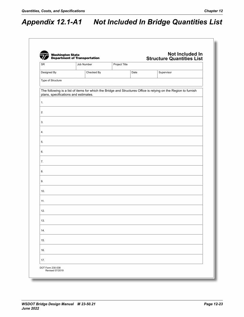
Quantities, Costs, and Specifications Chapter 12
WSDOT Bridge Design Manual M 23-50.21 Page 12-23 June 2022
Appendix 12.1-A1 Not Included In Bridge Quantities List
DOT Form 230-038 Revised 07/2019
Not Included In Structure Quantities List
SR Job Number Project Title
Designed By Checked By Date Supervisor
Type of Structure
The following is a list of items for which the Bridge and Structures Office is relying on the Region to furnish plans, specifications and estimates.
1.
2.
3.
4.
5.
6.
7.
8.
9.
10.
11.
12.
13.
14.
15.
16.
17.

Chapter 12 Quantities, Costs, and Specifications
Page 12-24 WSDOT Bridge Design Manual M 23-50.21 June 2022
Appendix 12.2-A1 Bridge Quantities
Bridge Quantities Bridge No. Date
St. Item No. Item Use Item Description Quantity Unit of
Measure 0001 Std. Item Mobilization L.S.
0061 Std. Item Removing Portion of Existing Bridge L.S. 0061 Type Area SF/SM
Drilled Holes: Less than 12” long: Greater than 12” long: Number Diameter
Inch Number Diameter
Inch
LengthLF
Inch Inch LF Inch Inch LF
Core Drilled Holes: Less than 12” long: Greater than 12” long: Number Diameter
Inch Number Diameter
Inch Length
LF Inch Inch LF Inch Inch LF
0071 Std. Item Removing Existing Bridge L.S. Type Area SF
0259 GSP Item Work Access L.S. Type Area SF
4001 GSP Item Temporary L.S. Bridge Type Area SF/SM
4006 Std. Item Structure Excavation Class A Incl. Haul CY Dry (includes unsuitable if specified by Geotech Report
Pier Soil CY CY CY CY
Cofferdam: Pier Soil Rock
CY CY CY CY CY CY CY CY
4010 Sp. Prov. Special Excavation CY Pier Soil
CY CY CY CY
DOT Form 230-031 Revised 05/2017
Page 1 of 5

Quantities, Costs, and Specifications Chapter 12
WSDOT Bridge Design Manual M 23-50.21 Page 12-25 June 2022
DOT Form 230-031 Revised 05/2017
St. Item No. Item Use Item Description Quantity Unit of Measure
4013 Std. Item Shoring or Extra Excavation Class A Dry:
AVERAGE OVERALL HEIGHT
L.S.
Pier <6 ft. 6 ft. to 10 ft 10 ft. to 20 ft*. >20 ft.* SF SF SF SF SF SF SF SF SF SF SF SF SF SF SF SF
COFFERDAM: AVERAGE OVERALL HEIGHT
PIER <6 ft. 6 ft. to10 ft 0 ft. to 20 ft.* >20 ft. SF SF SF SF SF SF SF SF SF SF SF SF SF SF SF SF
*INDICATE AVERAGE HEIGHT
7070 GSP Item Rock Bolt Each 7071 4008 Varies Varies
GSP Item Std. Item Std. Item. Std. Item
Rock Dowel Type Rock Excavation For Shaft Including Haul Constructing FT. Diam. Shaft Shaft - In. Diameter
Each CY LF LF
4053 4160
Std. Item Std. Item.
Furnishing Soldier Pile QA Shaft Test
LF Each
0256 Varies 4060 4070 4080 4085 4090 4095 4100 4105 4107 4108 4111 4116 8376 4130 4140
--
Std. Item GSP Item Std. Item Std. Item Std. Item Std. Item Std. Item Std. Item Std. Item Std. Item Std. Item Std. Item Std. Item Std. Item Std. Item Std. Item Std. Item Sp. Prov.
Removing Shaft Obstructions Preboring For Pile Furnishing and Driving Concrete Test Pile Furnishing Conc. Piling - Diameter Driving Conc. Pile Furnishing and Driving Steel Test Pile Furnishing Steel Piling Driving Steel Pile Furnishing and Driving Timber Test Pile Furnishing Timber Piling - Untreated Furnishing Timber Piling Driving Timber Pile - Untreated Driving Timber Pile Pile Splice - Timber Furnishing Steel Pile Tip or Shoe Placing Prestressed Hollow Concrete Pile Driving Prestreessed Hollow Concrete Pile Pile Loading Test
Est. LF
Each LF
Each FM
Each Each LF LF
Each Each Each Each Each
LF
4144 4148 4149 4151
Std. Item Std. Item Std. Item Std. Item
No. of Tests Each Pile Size Epoxy-Coated St. Reinf. Bar For Epoxy-Coated St. Reinf Bar For Bridge St. Reinf. Bar For Bridge St. Reinf Bar for
Ton/Tonne LB LB LB LB
Page 2 of 5

Chapter 12 Quantities, Costs, and Specifications
Page 12-26 WSDOT Bridge Design Manual M 23-50.21 June 2022
DOT Form 230-031 Revised 05/2017
St. Item No. Item Use Item Description Quantity Unit of Measure
4151 Std. Item St. Reinf Bar for LB -- Sp. Prov. Wire Mesh SY
4166 Std. Item Lean Concrete CY -- Std. Item Conc. Class CY
4322 Std. Item Conc. Class 4000 for Bridge CY 4202 Std. Item Conc. Class 4000 for CY 4200 Std. Item Conc. Class 3000 for CY 4325 Std. Item Conc. Class 5000 for Bridge CY 4205 Std Item Conc. CLass 5000 for CY 4324 Std. Item Conc. Class 4000W for Bridge CY 4204 Std. Item Conc. Class 4000W for CY
-- GSP Item Conc. Class EA CY -- SP Prov. Conc. Class HE CY
4230 Std. Item Structural Carbon Steel LB 4235 Std. Item Structural Low Alloy Steel LB 4240 Std. Item Structural High Strength Steel LB 4246 Std. Item Cast Steel LB 4251 Std. Item Forged Steel LB 4256 Std. Item Cast Iron LB 4261 Std. Item Malleable Iron LB 4267 Std. Item Ductile Iron LB 4271 Std. Item Cast Bronze LB 4299 Std. Item Lagging SF 4280 Std. Item Timber and Lumber - Untreated MBM 4282 Std. Item Timber and Lumber - Creosote Treated MBM 4284 Std. Item Timber and Lumber - Slats Treated MBM 4300 Std. Item Superstructure (for Concrete Bridges)
L.S. Bridge Plan Area SF
4311 Std. Item Bridge Deck (for Steel Bridges) L.S.
Bridge Plan Area SF 6945 Std. Item Conduit Pipe 2” Diam. LF 4410 Std. Item Bridge Railing Type LF 4420 GSP Item Bridge Grate Inlet Each 7169 Std. Item Structural Earth Wall SF
-- Sp. Prov. -- Sp. Prov.
5656 Std. Item Bridge Approach Slab SY
Page 3 of 5

Quantities, Costs, and Specifications Chapter 12
WSDOT Bridge Design Manual M 23-50.21 Page 12-27 June 2022
DOT Form 230-031 Revised 05/2017
Breakdown of Items for Superstructure or Bridge Deck Unit of
St. Item No. Item Use Item Description Quantity Measure -- Std. Item Epoxy-Coated Steel Reinforcing Bar LB -- Std. Item Epoxy-Coated Steel Reinforcing Bar (Traffic Barrier) LB -- Std. Item Steel Reinforcing Bar LB -- Conc. Class CY -- Std. Item Conc. Class 4000D CY -- Std. Item Conc. Class 4000 CY -- Std. Item Conc. Class 5000 CY -- Std. Item Conc. Class CY -- Std. Item Structural Carbon Steel
LS LB
-- Std. Item Structural Low Alloy Steel LB -- Std. Item Structural High Strength Steel LB -- Std. Item Cast Steel LB -- Std. Item Cast Iron LB -- Std. Item Malleable Iron LB -- Std. Item Ductile Iron LB -- Std. Item Cast Bronze LB -- Std. Item Timber and Lumber - Untreated MBM -- Std. Item Timber and Lumber - Creosote Treated MBM -- Std. Item Timber and Lumber - Salts Treated MBM -- Sp. Prov. Glulam Deck Panels MBM
6945 Std. Item Conduit Pipe 2” Diameter LF -- Std. Item Bridge Railing Type LF -- Std. Item Traffic Barrier LF
4433 GSP. Item. Modify Bridge Drain Each 4434 GSP Item Plugging Existing Bridge Drain Each 4420 GSP Item Bridge Grate Inlet Each Varies GSP Item Expansion Joint System LF
Type Length LF Type Length LF Type Length LF
4444 GSP Item Expansion Joint Modification LF Type Length LF
4232 Std. Item Modified Concrete Overlay CF 4233 Std. Item Finishing and Curing Modified Concrete Overlay SY 4456 Std. Item Scarifying Concrete Surface SY
BSP Item Polymer Concrete Overlay SY 4465 Std. Item Further Deck Preparation (for Type 1 Deck Repair) SF 4467 Std. Item Further Deck Preparation for Type 2 Deck Repair SF 4451 Std. Item Bridge Deck Repair Br No SF 4455 Std. Item Waterproof Membrame Br No SY
SY -- Sp. Prov. Pot Bearing
5708 Std. Item Removing Existing Overlay from Bridge Deck Each
-- BSP Item Disc Bearing Each
Page 4 of 5

Chapter 12 Quantities, Costs, and Specifications
Page 12-28 WSDOT Bridge Design Manual M 23-50.21 June 2022
DOT Form 230-031 Revised 05/2017
----------
----
----
4269
BSP Item BSP Item Std. Item Sp., Prov. GSP Item Std. Item Std. Item Sp. Prov.
Sp. Prov. Sp. Prov.
Spherical Bearing Cylindrical Bearing Elastomeric Bering Pad (for pads only) Elastomeric Bearing Pad Assembly (for a fabricated assembly) Fabric Pad Bearing Prestressed Conc. Girder Prestressing Precast Segment Volume CY/CM
Each Each Each Each Each LF LB LF
Page 5 of 5

Quantities, Costs, and Specifications Chapter 12
WSDOT Bridge Design Manual M 23-50.21 Page 12-29 June 2022
Appendix 12.3-A1 Structural Estimating Aids Construction Costs

Chapter 12 Quantities, Costs, and Specifications
Page 12-30 WSDOT Bridge Design Manual M 23-50.21 June 2022
SPECIAL NOTE: These cost estimate aids do not account for recent effects due to inflation, labor and equipment shortages,supply chain issues, and other environmental and economic factors.
For the most recent bid history see:
Unit Bid Analysishttps://wsdot.wa.gov/engineering-standards/design-topics/engineering-applications/unit-bid-analysis
Bid Tabulationshttps://wsdot.wa.gov/business-wsdot/how-do-business-us/public-works-contracts/public-works-contract-history/bid-tabulations
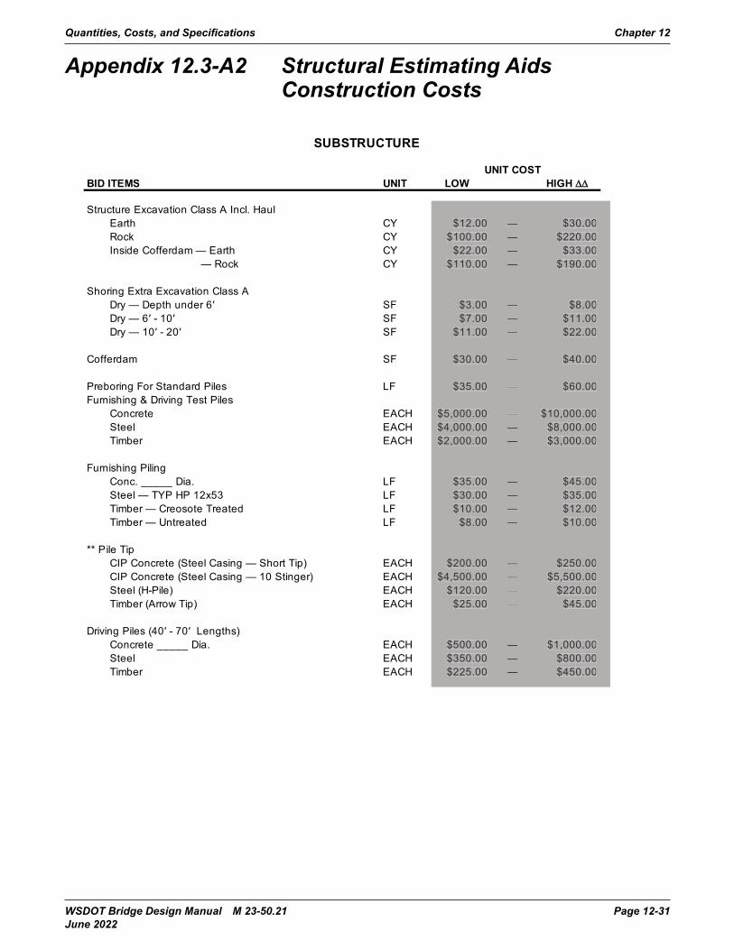
Quantities, Costs, and Specifications Chapter 12
WSDOT Bridge Design Manual M 23-50.21 Page 12-31 June 2022
Appendix 12.3-A2 Structural Estimating Aids Construction Costs

Chapter 12 Quantities, Costs, and Specifications
Page 12-32 WSDOT Bridge Design Manual M 23-50.21 June 2022
See SPECIAL NOTE on Appendix 12.3-A1 for updates and additional resources on unit costs.
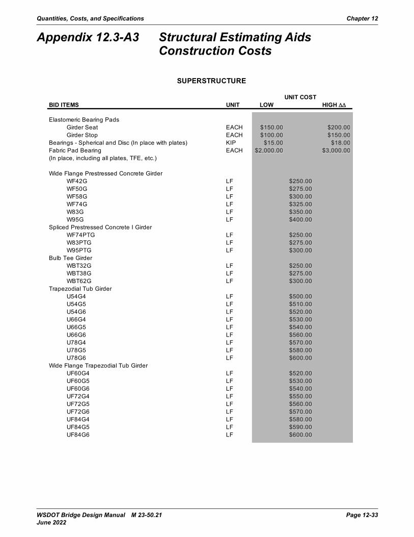
Quantities, Costs, and Specifications Chapter 12
WSDOT Bridge Design Manual M 23-50.21 Page 12-33 June 2022
Appendix 12.3-A3 Structural Estimating Aids Construction Costs
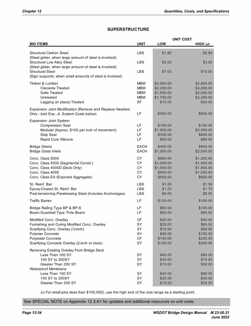
Chapter 12 Quantities, Costs, and Specifications
Page 12-34 WSDOT Bridge Design Manual M 23-50.21 June 2022
See SPECIAL NOTE on Appendix 12.3-A1 for updates and additional resources on unit costs.

Quantities, Costs, and Specifications Chapter 12
WSDOT Bridge Design Manual M 23-50.21 Page 12-35 June 2022
Appendix 12.3-A4 Structural Estimating Aids Construction Costs
See SPECIAL NOTE on Appendix 12.3-A1 for updates and additional resources on unit costs.

Chapter 12 Quantities, Costs, and Specifications
Page 12-36 WSDOT Bridge Design Manual M 23-50.21 June 2022
Appendix 12.3-B1 Cost Estimate Summary
Bridge Design Manual M 23-50.02 Page 12.3-B1-1May 2008
Appendix 12.3-B1 Cost Estimate SummarySR
162
700
2 C
arbo
n
R
iver
Brid
ge 1
62/1
4 __
____
____
____
____
____
____
____
____
____
____
____
____
____
____
____
____
____
__
Date of Transmittal
Estim
ate
of C
ost
Assume Accuracy %
Estimate Made By
Avai
labl
e D
ata
Cop
ies
Sent
To
Rem
arks
Field Data (Dated)
Date Layout Made
Foundation Date Rec.
Preliminary Quantities
Final Quantities
Estimate By Sq. Ft. Area
District
Design Branch
Program Development
10-2
-91
$517
,000
.00
±15%
DM
J8-
91—
3Pl
ease
See
Cov
er T
rans
mitt
al
1-9-
92$6
92,0
00.0
0±1
0%LH
T
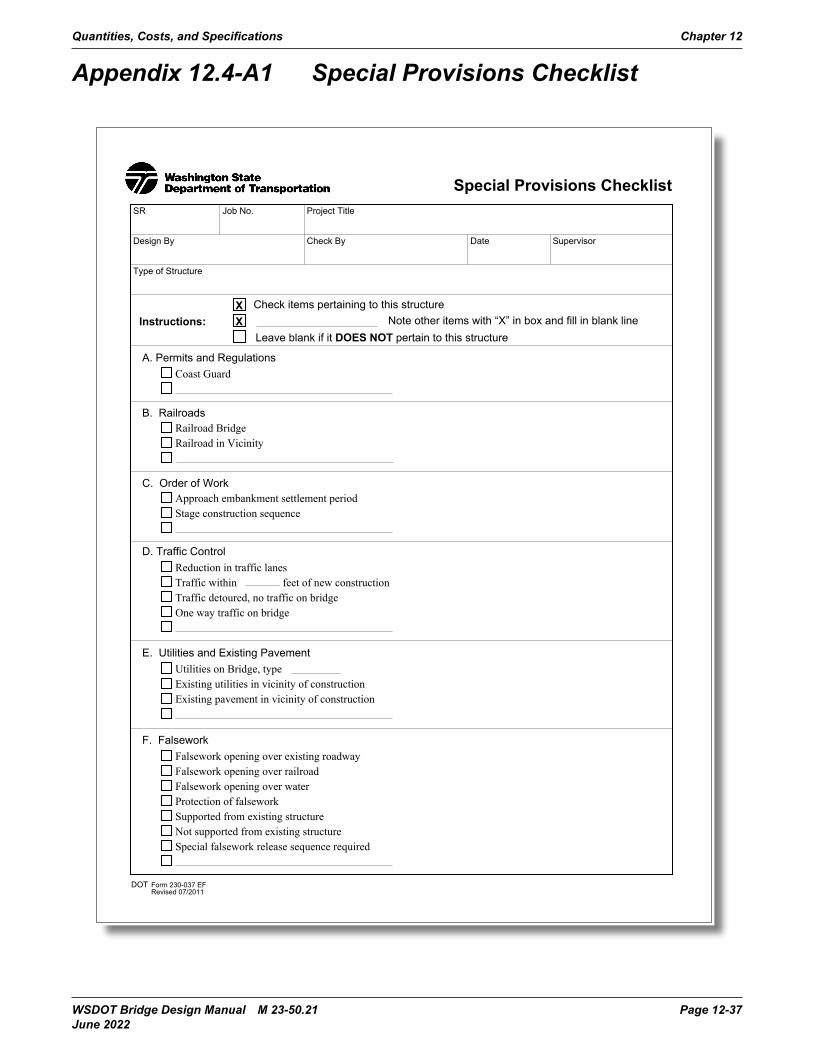
Quantities, Costs, and Specifications Chapter 12
WSDOT Bridge Design Manual M 23-50.21 Page 12-37 June 2022
Appendix 12.4-A1 Special Provisions Checklist
K. Prestressed Concrete Griders
L. Superstructure
DOT Form 230-037 EFRevised 07/2011
M. Steel Structure
N. Timber Structures
T. Waterproofing
U. Miscellaneous Items
DOT Form 230-037 EFRevised 07/2011
V. Metal Bridge Railing
W. Repair Work
X. Other Items
psi at day, location
DOT Form 230-037 EFRevised 07/2011
G. Foundation
H. Forms
I. Piles
J. Shafts
inch diameter
O. Signing and Lighting
P. Drainage System
DOT Form 230-037 EFRevised 07/2011
Q. Surface Finish
R. Special Classes of Concrete
S. Bridge Widening or Replacement
psi at day, location
, salvage item
Special Provisions ChecklistSR
DOT Form 230-037 EFRevised 07/2011
Job No.
Design By
Project Title
Check By Date Supervisor
Type of Structure
Instructions:X Check items pertaining to this structureX Note other items with “X” in box and fill in blank line
Leave blank if it DOES NOT pertain to this structure
A. Permits and RegulationsCoast Guard
B. RailroadsRailroad Bridge
C. Order of WorkApproach embankment settlement period
D. Traffic ControlReduction in traffic lanes
E. Utilities and Existing PavementUtilities on Bridge, type
F. FalseworkFalsework opening over existing roadway
Railroad in Vicinity
Stage construction sequence
Traffic withinTraffic detoured, no traffic on bridgeOne way traffic on bridge
Existing utilities in vicinity of constructionExisting pavement in vicinity of construction
Falsework opening over railroadFalsework opening over waterProtection of falseworkSupported from existing structureNot supported from existing structureSpecial falsework release sequence required
feet of new construction

Chapter 12 Quantities, Costs, and Specifications
Page 12-38 WSDOT Bridge Design Manual M 23-50.21 June 2022
K. Prestressed Concrete Griders
L. Superstructure
DOT Form 230-037 EFRevised 07/2011
M. Steel Structure
N. Timber Structures
T. Waterproofing
U. Miscellaneous Items
DOT Form 230-037 EFRevised 07/2011
V. Metal Bridge Railing
W. Repair Work
X. Other Items
psi at day, location
DOT Form 230-037 EFRevised 07/2011
G. FoundationExcavation near existing pavement
H. FormsSpecial forms for architectural treatment
I. PilesConcrete test pile
Excavation near railroad track or facilitiesConcrete SealsSeal construction using a bermCofferdamsPumping water from foundation excavation requiredRiprap at piersRemoval of unsuitable materialRock excavation requiring threshold limit valueSpecial Excavation
Fractured Fin Finish
Remove forms from cells which have access (Box grider)
Concrete pilingSteel test pileSteel pilingTimber Test PileTimber pilingPile loading testPile minimum tip elevationsPile splicePile tipPreboring for pileDriving piles in highly developed business or residential areasExcavation for pileDriving from existing structureNo driving from existing structure
J. ShaftsRequired permanent casingRequired temporary casingCasing shoringShaft SealCSL access tubes
Variable depth random board finish3/4 inch random board finish
inch diameter
O. Signing and Lighting
P. Drainage System
DOT Form 230-037 EFRevised 07/2011
Q. Surface Finish
R. Special Classes of Concrete
S. Bridge Widening or Replacement
psi at day, location
, salvage item
Special Provisions ChecklistSR
DOT Form 230-037 EFRevised 07/2011
Job No.
Design By
Project Title
Check By Date Supervisor
Type of Structure
Instructions:X Check items pertaining to this structureX Note other items with “X” in box and fill in blank line
Leave blank if it DOES NOT pertain to this structure
A. Permits and Regulations
B. Railroads
C. Order of Work
D. Traffic Control
E. Utilities and Existing Pavement
F. Falsework
feet of new construction
Overdriving of piles

Quantities, Costs, and Specifications Chapter 12
WSDOT Bridge Design Manual M 23-50.21 Page 12-39 June 2022
K. Prestressed Concrete GridersEpoxy - coated prestressing steel
L. Superstructure
Concrete class
Precast prestressed memberSpliced prestressed concrete girder
DOT Form 230-037 EFRevised 07/2011
Prestressed concrete tub girder
Post - tensioning tendonsElastomeric bearing pads (pad only)
Fabric pad bearingDisc bearingSpherical bearingCylindrical bearingElectrical ConduitExpansion joint
M. Steel StructureStructural Carbon SteelStructural Low Alloy SteelStructural H.S. SteelSteel CastingA - 307 FastenersM - 164 FastenersF-1554 FastenersShop AssemblingNotch Toughness RequirementsApplication of Paint - Color No.Steel Erection
N. Timber StructuresUntreatedCreosote treatedSalt treatedGlulam deck panelsType and grade of timberFire prevention requirement needed
Temporary strandsf'c 28 days > 8,500 psi
T. Waterproofing
U. Miscellaneous Items
DOT Form 230-037 EFRevised 07/2011
V. Metal Bridge Railing
W. Repair Work
X. Other Items
psi at day, location
DOT Form 230-037 EFRevised 07/2011
G. Foundation
H. Forms
I. Piles
J. Shafts
inch diameter
O. Signing and Lighting
P. Drainage System
DOT Form 230-037 EFRevised 07/2011
Q. Surface Finish
R. Special Classes of Concrete
S. Bridge Widening or Replacement
psi at day, location
, salvage item
Special Provisions ChecklistSR
DOT Form 230-037 EFRevised 07/2011
Job No.
Design By
Project Title
Check By Date Supervisor
Type of Structure
Instructions:X Check items pertaining to this structureX Note other items with “X” in box and fill in blank line
Leave blank if it DOES NOT pertain to this structure
A. Permits and Regulations
B. Railroads
C. Order of Work
D. Traffic Control
E. Utilities and Existing Pavement
F. Falsework
feet of new construction
Elastomeric bearing pad assembly (fabricated assembly)

Chapter 12 Quantities, Costs, and Specifications
Page 12-40 WSDOT Bridge Design Manual M 23-50.21 June 2022
K. Prestressed Concrete Griders
L. Superstructure
DOT Form 230-037 EFRevised 07/2011
M. Steel Structure
N. Timber Structures
T. Waterproofing
U. Miscellaneous Items
DOT Form 230-037 EFRevised 07/2011
V. Metal Bridge Railing
W. Repair Work
X. Other Items
psi at day, location
DOT Form 230-037 EFRevised 07/2011
G. Foundation
H. Forms
I. Piles
J. Shafts
inch diameter
O. Signing and LightingNavigation lighting systemTemporary navigation lightSign bridge on structureCantilever sign structure on bridgeBridge mounted sign brackets
P. Drainage System Special bridge drainsBridge grate inletsDownspout
DOT Form 230-037 EFRevised 07/2011
Q. Surface FinishFractured fin finishSandblast finish
Pigmented sealer
R. Special Classes of ConcreteConcrete Class EAConcrete Class HE
S. Bridge Widening or Replacement
Removing portions of existing structureSalvage Materials, storage siteCoating contrete surface with epoxy resinDrilling holesCore drilled holesSet rebar with epoxyUse of rockbolts or rock anchorsGrout, comp. strengthAs built Plans of existing structure available for bidder's inspectionHMA overlayLMC overlayPolyester concrete overlayBridge deck repairFurther deck preparation
Complete removal of existing structure
Explosive prohibitedExplosives allowed
3/4 inch random board finishVariable depth random board finish
psi at day, location
, salvage item
Special Provisions ChecklistSR
DOT Form 230-037 EFRevised 07/2011
Job No.
Design By
Project Title
Check By Date Supervisor
Type of Structure
Instructions:X Check items pertaining to this structureX Note other items with “X” in box and fill in blank line
Leave blank if it DOES NOT pertain to this structure
A. Permits and Regulations
B. Railroads
C. Order of Work
D. Traffic Control
E. Utilities and Existing Pavement
F. Falsework
feet of new construction

Quantities, Costs, and Specifications Chapter 12
WSDOT Bridge Design Manual M 23-50.21 Page 12-41 June 2022
K. Prestressed Concrete Griders
L. Superstructure
DOT Form 230-037 EFRevised 07/2011
M. Steel Structure
N. Timber Structures
T. WaterproofingMembrane waterproofing (Deck Seal)
U. Miscellaneous ItemsTemporary oak blocksPoured rubberExpaned polstyrenePlastic waterstopsExpanded rubberButyl rubber sheetingGrout, comp. strengthElectrical conduit
DOT Form 230-037 EFRevised 07/2011
V. Metal Bridge RailingBridge Railing Type BPBridge Railing Type
W. Repair WorkEpoxy Crack SealingTimber RedeckingConcrete Deck Repair
X. Other ItemsCeramic TilesSturctural Earth WallTieback WallNoise Barrier WallWinter ConditionsWork AccessWork hours or seasonal restritionWork BridgeDetour Bridge
psi at day, location
DOT Form 230-037 EFRevised 07/2011
G. Foundation
H. Forms
I. Piles
J. Shafts
inch diameter
O. Signing and Lighting
P. Drainage System
DOT Form 230-037 EFRevised 07/2011
Q. Surface Finish
R. Special Classes of Concrete
S. Bridge Widening or Replacement
psi at day, location
, salvage item
Special Provisions ChecklistSR
DOT Form 230-037 EFRevised 07/2011
Job No.
Design By
Project Title
Check By Date Supervisor
Type of Structure
Instructions:X Check items pertaining to this structureX Note other items with “X” in box and fill in blank line
Leave blank if it DOES NOT pertain to this structure
A. Permits and Regulations
B. Railroads
C. Order of Work
D. Traffic Control
E. Utilities and Existing Pavement
F. Falsework
feet of new construction

Chapter 12 Quantities, Costs, and Specifications
Page 12-42 WSDOT Bridge Design Manual M 23-50.21 June 2022
Appendix 12.4-A2 Structural Estimating Aids Construction Time Rates
Operation Units** Min. Output Ave. Output Max. OutputSubstructureStructure Exc. & Shoring CY/DAY 20 80 150*Seals CY/DAY 10 15 20*Footings CY/DAY 6 10 14*Abutment Walls CY/DAY 4 7 19*Wingwalls CY/DAY 1 1.5 2*Retaining Walls with Footings CY/DAY 4 11 17*Columns CY/DAY 3 4 8Falsework for X-beams CY/DAY 4 10 13*X-beams CY/DAY 16 18 20Furnishing PilesPrecast Concrete DAYS 40 30 20Cast-in-Place Concrete DAYS 15 5 2Steel DAYS 30 10 2Timber DAYS 20 5 2Driving PilesDriving Test Piles EACH/DAY 1 1 2Concrete LF/DAY 100 150 200Steel LF/DAY 100 150 200Timber LF/DAY 100 150 200Shafts DAYS 2 3 4Soldier Pile WallsDriving Soldier Pile DAYS 2 3 4Permanent Ground Anchor EACH 1 4 10Timber Lagging MBM/DAY 1 2 4Concrete Fascia Panel SF/DAY 100 800 1500Soil Nail WallsSoil Nail EACH 1 4 10Shotcrete Facing SF/DAY 1200 3000 6000SuperstructurePrestressed GirdersGirder Fabrication DAYS 70 45 35Set Girders LF/DAY 200 550 1,450*Slab & Diaphragms CY/DAY 6 11 18*Concrete**All times are based on a single crew with 8-hour work DAYS

Quantities, Costs, and Specifications Chapter 12
WSDOT Bridge Design Manual M 23-50.21 Page 12-43 June 2022
Operation Units** Min. Output Ave. Output Max. OutputBox GirdersSpan Falsework SF/DAY 150 700 900*Bottom Slab CY/DAY 3 8 11*Webs, Diaphragms, and X-beams CY/DAY 5 18 25*Top Slab CY/DAY 7 9 12Stress and Grout Strands LBS/DAY 4,500 6,000 8,000Strip Falsework SF/DAY 1,500 2,200 3,000T-BeamSpan Falsework SF/DAY 500 700 1,000*Girders, Diaphragms, and Slab CY/DAY 6 10 15Strip Falsework SF/DAY 1,000 1,500 2,000Flat SlabSpan Falsework SF/DAY 100 250 600*Slab and X-beams CY/DAY 6 10 15Strip Falsework SF/DAY 300 500 1,000Steel GirderGirder Fabrication DAYS 200 150 110Girder Erection LF/DAY 50 100 200*Slab CY/DAY 6 10 15Painting SF/DAY 1,000 2,000 3,000Miscellaneous*Traffic Barrier LF/DAY 20 40 80*Traffic Railing & Sidewalk LF/DAY 15 35 60*SEW Traffic Barrier LF/DAY 15 35 60*Concrete Deck Overlay SY/DAY 200 250 300Expansion Joint Replacement DAYS/LANE
CLOSURE8 6 4
Bridge Rail Retrofit LF/DAY 50 100 200
* Concrete** All times are based on a single crew with 8-hour work DAYS
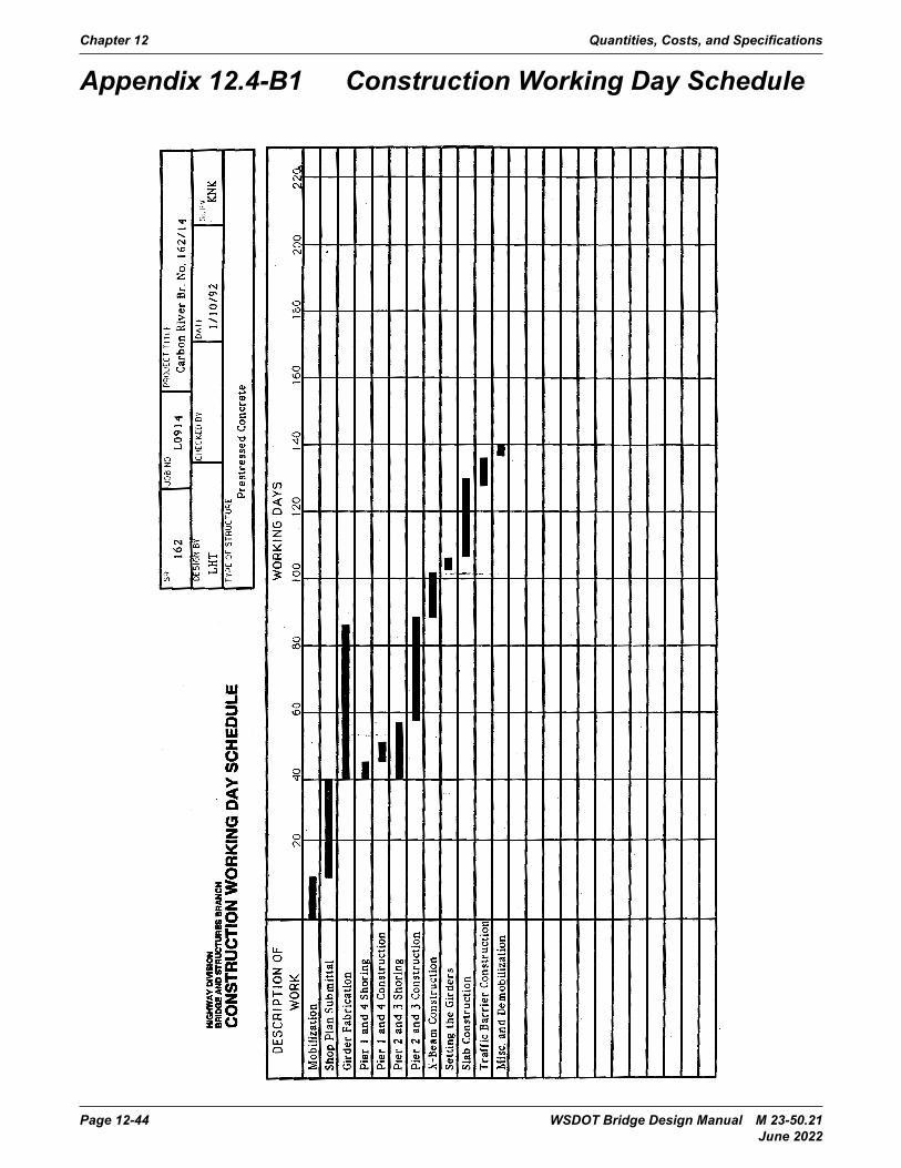
Chapter 12 Quantities, Costs, and Specifications
Page 12-44 WSDOT Bridge Design Manual M 23-50.21 June 2022
Appendix 12.4-B1 Construction Working Day Schedule
Bridge Design Manual M 23-50 Page 12.4-B1-1August 2006
Appendix 12.4-B1 Construction Working Day Schedule