Eletric bicycle by ups battery final
63
CHAPTER 1 1.1 INTRODUCTION An electrically powered bi-cycle includes a frame mounted motor connected to pedals and to a rear driven wheel through an intermediate sprocket. The motor is connected to the sprocket through a chain .The pedals are connected to the sprocket through a chain and a sprocket t-pedal freewheel which allow the pedals to drive the sprocket, but prevents the sprocket from driving the pedals. The sprocket is connected to the driven wheel through the another chain, and a second freewheel allows the sprocket to drive the driven wheel but prevents the driven wheel from driving the sprocket using the same chain .another chain may additionally connect the driven wheel to the sprocket through a third freewheel to recharge batteries during braking or while coasting downhill. The present invention also encompasses an apparatus and method for a pedal and electric powered vehicles free wheel mounted to either the wheel hub or the drive portion of the motor, another sprocket mounted to the other of the wheel hub or the drive portion of the motor and another chain connecting the sprocket to the free wheel so that the wheel can drive the motor for regenerative braking. 1.2 BACKGROUND Over the last 150 years, the bicycle has evolved to become one of the most efficient means of transportation in terms of conversion of energy into distance travelled. For example, most modern bicycles require only about 400 watts (½ horsepower) to propel the bicycle at 15 M.P.H. on level ground. The efficiency of the bicycle has also been optimized to minimize the effort required by the rider. For instance, most modern bicycles include an efficient gear system to minimize rider effort. The human muscle and modern battery are similar in their ability to produce power from 1
Transcript of Eletric bicycle by ups battery final

CHAPTER 1
1.1 INTRODUCTIONAn electrically powered bi-cycle includes a frame mountedmotor connected to pedals and to a rear driven wheel throughan intermediate sprocket. The motor is connected to thesprocket through a chain .The pedals are connected to thesprocket through a chain and a sprocket t-pedal freewheelwhich allow the pedals to drive the sprocket, but preventsthe sprocket from driving the pedals. The sprocket isconnected to the driven wheel through the another chain, anda second freewheel allows the sprocket to drive the drivenwheel but prevents the driven wheel from driving thesprocket using the same chain .another chain mayadditionally connect the driven wheel to the sprocketthrough a third freewheel to recharge batteries duringbraking or while coasting downhill.The present invention also encompasses an apparatus andmethod for a pedal and electric powered vehicles free wheelmounted to either the wheel hub or the drive portion of themotor, another sprocket mounted to the other of the wheelhub or the drive portion of the motor and another chainconnecting the sprocket to the free wheel so that the wheelcan drive the motor for regenerative braking.
1.2 BACKGROUNDOver the last 150 years, the bicycle has evolved to becomeone of the most efficient means of transportation in termsof conversion of energy into distance travelled. Forexample, most modern bicycles require only about 400 watts(½ horsepower) to propel the bicycle at 15 M.P.H. on levelground. The efficiency of the bicycle has also beenoptimized to minimize the effort required by the rider. Forinstance, most modern bicycles include an efficient gearsystem to minimize rider effort. The human muscle and modernbattery are similar in their ability to produce power from
1

stored energy. Similarly, both are able to produce moreenergy by keeping the torque per stroke low and thefrequency high. The gears of modern bicycle allow the riderto exercise the muscle in the aerobic range to allowcontinuous long distance riding. The gears are utilized tokeep the rider's pedal speed at a high rotating speed(usually between about 60 to 100 rpm). At higher pedalingspeeds, the force output for muscle contraction is low sothat the muscle is able to stay in the aerobic region
1.3 Importance of the work:Day by day pollution is overwhelming all major cities of ourcountry. The main reasons are the air and noise pollution caused by transport vehicles and significant part comes frompetrol and diesel-powered motorbikes and three wheelers. There are presently nearly half a millions of petrol- powered there wheelers.A limited number of three wheelers are operated with CNG. Pollution from these vehicles is growing at a significant rate.
2

Due to the unavailability of rickshaws personal vehicle isneeded for the person who works in a place far away fromhis/her residence. Motor cycle or private car is expensive.The number of three or four wheeler vehicle is increased dayby day. It creates traffic jam in a narrow road or point ofroad. Auto Rickshaws are being parked in the busyroad as well as foot path and traffic jams are theconsequence of the mismanagement.
We can use a bicycle for personal use but always driving thepedal to running the bicycle. Pedal driving is physicallyhard but we cannot drive (max 3-4 km) a long journey. InElectric Bicycle we can easily drive (22-25 km) a longjourney depends on battery charge. When the batteries don’thave enough charges, we can use pedal to reach thedestination.
1.4 OBJECTIVE
To construct an electrical bi cycle by using a dc motorand UPS battery as the power source.
To modify an existing dc battery charger to decrease the charging time.
3

1.5 PROPOSED SYSTEM
4

Figure 1.5 Graphical View of Proposed System
CHAPTER 2
2.1 HARDWARE COMPONENT
1. Bicycle Frame.2. Bicycle Brake.3. Bicycle Wheel.4. Bicycle Chain.5. Ball Bearing.6. Spoke.7. Bicycle Pedal.8. Free HUB.
2.2 Bicycle frame
A bicycle frame is the main component of a bicycle ontowhich wheels and other components are fitted. The modern andmost common frame design for an upright bicycle is based onthe safety bicycle, and consists of two triangles, a maintriangle and a paired rear triangle. This is known as thediamond frame. Frames are required to be strong, stiff andlight, which they do by combining different materials andshapes.
5

Figure 2.2: Bicycle frame
2.2.1 Frame size:
Frame size was traditionally measured along the seat tubefrom the center of the bottom bracket to the center of thetop tube. Typical "medium" sizes are 54 or 56 cm(approximately 21.2 .The wider ranges of frame geometriesthat are now made have given rise to different ways ofmeasuring frame size. Touring frames tend to be longer,while racing frames are more compact
6

Figure 2.2.1 Frame size
2.3 Bicycle handlebar
Bicycle handlebars refers to the steering mechanismfor bicycles; the equivalent of a steering wheel. Besidessteering, handlebars also often support a portion of therider's weight, depending on their riding position, andprovide a convenient mounting place for brake levers, shiftlevers, cycle computers, bells, etc. Handlebars are attachedto a bike's stem which in turn attaches to the fork.
Figure 2.3: Bicycle handlebar
2.4 Bicycle saddleA bicycle saddle, often called a seat, is one of threecontact points on an upright bicycle, the others beingthe pedals and the handlebars. The bicycle saddle has beenknown as such since the bicycle evolved from the raisin, aforerunner of the bicycle. It performs a similar role as ahorse's saddle, not bearing all the weight of the rider asthe other contact points also take some of the load.
A bicycle saddle is commonly attached to the seat post andthe height of the saddle can usually be adjusted by the seatpost telescoping in and out of the seat tube.
7

Figure 2.4 Bicycle Saddle
2.5 Bicycle Brake:
8

A bicycle brake reduces the speed of a bicycle or prevents it from moving. The three main types are: rim brakes, disc brakes, and drum brakes. There have been various types of brakes used throughout history, and several are still in usetoday.
Most bicycle brake systems consist of three main components:a mechanism for the rider to apply the brakes, such as brakelevers or pedals; a mechanism for transmitting that signal, such as Bowden cables, hydraulic hoses, rods, or the bicyclechain; and the brake mechanism itself, a caliper or drum, topress two or more surfaces together in order to convert, viafriction, kinetic energy Kinetic energy of the bike and rider into thermal energy to be dissipated.
9

Figure 2.5: Bicycle Brake
2.6 Bicycle Wheel : A bicycle wheel is a wheel, most commonly a wire wheel,designed for a bicycle. A pair is often called a wheel set,especially in the context of ready built "off the shelf"performance-oriented wheels.Bicycle wheels are typically designed to fit intothe frame and fork via dropouts, and hold bicycle tires.
Figure2.6: Bicycle Wheel
2.7 Bicycle Chain
A bicycle chain is a roller chain that transfers power fromthe pedals to the drive-wheel of a bicycle, thus propelling
10
it. Most bicycle chains are made from plain carbon or alloysteel, but some are nickel plated to prevent rust, or simplyfor aesthetics.
Figure 2.7: Bicycle Chain
2.8 Ball Bearing A ball bearing is a type of rolling-element bearing thatuses balls to maintain the separation betweenthe bearing races.
The purpose of a ball bearing is to reduce rotationalfriction and support radial and axial loads. It achievesthis by using at least two races to contain the balls andtransmit the loads through the balls. In most applications,one race is stationary and the other is attached to therotating assembly (e.g., a hub or shaft). As one of thebearing races rotates it causes the balls to rotate as well.Because the balls are rolling they have a muchlower coefficient of friction than if two flat surfaces weresliding against each other.
Ball bearings tend to have lower load capacity for theirsize than other kinds of rolling-element bearings due to thesmaller contact area between the balls and races. However,
11

they can tolerate some misalignment of the inner and outerraces.
Figure 2.8: Ball Bearing
2.9 Free hub A free hub is a type of bicycle hub that incorporatesa ratcheting mechanism, and the name free hub is aregistered trademark of Shimano. A set of sprockets (called
12

a cassette") are mounted onto a splined shaft of the freehub to engage the chain. The ratcheting mechanism is a partof the hub, in contrast to a free wheel, an oldertechnology, which contains both the sprockets and aratcheting mechanism in a single unit separate from the hub.In many high-end and midrange bicycles, free hubs havereplaced freewheel systems.
A freewheel mechanism allows a rider to stop pedaling whilstthe cycle is still in forward motion. On a cycle without afreewheel mechanism, the rider has to keep pedaling wheneverthe cycle is moving.
13

Figure 2.9 Free hub
2.10 Spoke
Spoke is one of some number of rods radiating from thecenter of a wheel (the hub where the axle connects),connecting the hub with the round traction surface.The term originally referred to portions of a log that hadbeen split lengthwise into four or six sections. The radialmembers of a wagon wheel were made by carving a spoke (froma log) into their finished shape. A spokes have isa tool originally developed for this purpose. Eventually theterm spoke was more commonly applied to the finished productof the wheelwright's work, than to the materials he used
14

Figure 2.10: Spoke
2.11 Bicycle Pedal A bicycle pedal is the part of a bicycle that the riderpushes with their foot to propel the bicycle. It providesthe connection between the cyclist's foot or shoe and thecrank allowing the leg to turn the bottom bracket spindleand propel the bicycle's wheels. Pedals usually consist ofa spindle that threads into the end of the crank and a body,on which the foot rests or is attached, that is free torotate on bearings with respect to the spindle.
Pedals were initially attached to cranks connecting directlyto the driven (usually front) wheel. The safety bicycle, asit is known today, came into being when the pedals wereattached to a crank driving a sprocket that transmittedpower to the driven wheel by means of a roller chain.
15

Figure 2.11: Pedal
CHAPTER 3
Implementation of the Bicycle
3.1 List of implementation
DC motor. The Controller Box. Battery. Charger. Throttle Position Sensor (TPS).
16

The Hand-Clutch and Power-Key. Speed Limiting Cable. Speed Control Mechanism of the Existing System. The throttle terminals. The shaft speed.
Dc Motor3.2.1 Motor Principle an Electric motor is a machine whichconverts electric energy into mechanical energy. Its actionis based on the principle that when a current-carrying conductor is placed in a magnetic field, it experiences a mechanical force whose direction is given by Fleming’s Left-hand Rule and whose magnitude is given by F = BIl Newton.
Figure 3.2.1: Principle of DC Motor
Construction ally, there is no basic difference between a dc. Generator and a dc. motor. In fact, the same dc.
17

Machine can be used interchangeably as a generator or as a motor. D.C. motors are also like generators, shunt-wound orseries-wound or compound-wound.
Figure 3.2.1 Multi Polar Dc Motor
When its field magnets are excited and its armature conductors are supplied with current from the supply mains, they experience a force tending to rotate the armature. Armature conductors
Under N-pole are assumed to carry current downwards (crosses) and those under S-poles, to carry current upwards (dots). By applying Fleming’s Left-hand Rule, the directionof the force on each conductor can be found. It is shown bysmall arrows placed above each conductor. It will be seen that each conductor can be found. It will be seen that eachconductor experiences a force F which tends to rotate the armature in anticlockwise direction. These forces collectively produce a driving torque which sets the armature rotating. It should be noted that the function of acommutator in the motor is the same as in a generator. By reversing current in each conductor as it passes from one pole to another, it helps to develop a continuous and unidirectional torque.
As said above, the same dc. Machine can be used, at least theoretically, interchangeably as a generator or as a motor.When operating as a generator, it is driven by a mechanical machine and it develops voltage which in turn produces a
18

current flow in an electric circuit. When operating as a motor, it is supplied by electric current and it develops torque which in turn produces mechanical rotation.
Let us first consider its operation as a generator and see how exactly and through which agency, mechanical power is converted into electric power. In Fig part of a generator whose armature is being driven clockwise by its prime mover is shown. Fig represents the fields set up independently by the main poles and the armature conductors like A in the figure. The resultant field or magnetic lines on flux are shown in Fig. It is seen that there is a crowding of lines of flux on the right-hand side of A. These magnetic lines of flux may be likened to the rubber bands under tension. Hence, the bent lines of flux up a mechanical force on a much in the same way as the bent elastic rubber band of a catapult produces a mechanical force on the stone piece. Itwill be seen that this force is in a direction opposite to that of armature rotation. Hence, it is known as backward force or magnetic drag on the conductors. It is against this drag action on all armature conductor that the prime
19

mover has to work. The work done in overcoming this opposition is converted into electric energy. Therefore, itshould be clearly understood that it is only through the instrumentality of this magnetic drag that energy conversionis possible in a dc generator.
Next, suppose that the above dc. Machine is un-coupled from its prime mover and that current is sent through the armature conductors under an N-pole in the downward direction as shown in Fig. 29.3 (a). The conductors will again experience a force in the anticlockwise direction
20

(Fleming’s Left hand Rule). Hence, the machine will start rotating anticlockwise, thereby developing a torque which can produce mechanical rotation. The machine is then said tobe motoring.
As said above, energy conversion is not possible unless there is some opposition whose overcoming provides the necessary means for such conversion. In the case of a generator, it was the magnetic drag which provided the necessary opposition. But what is the equivalent of that drag in the case of a motor? Well, it is the back e.m.f. It is explained in this manner: As soon as the armature starts rotating, dynamically (or motion ally) induced e.m.f.is produced in the armature conductors. The direction of this induced e.m.f. as found by Fleming’s Right-hand Rule, is outwards i.e., in direct opposition to the applied voltage (Fig. 29.3 (b)). This is why it is known as back e.m.f. Eb or counter e.m.f. Its value is the same as for the motion ally induced e.m.f. in the generator i.e. Eb = (ΦZN) × (P/A) volts. The applied voltage V has to be force current through the armature conductors against this.
Back e.m.f. Eb. The electric work done in overcoming thisopposition is converted into mechanical energy developed inthe armature. There-fore, it is obvious that but for theproduction of this opposing e.m.f. energy conversion wouldnot have been possible. In fact, it seems to be one of the
21

fundamental laws of Nature that no energy conversion fromone form to another is possible until there is someone to
oppose the conversion. But for the presence of thisopposition, there would simply be no energy conversion. Ingenerators, opposition is provided by magnetic drag whereasin motors, back e.m.f. does this job. Moreover, it is onlythat part of the input energy which is used for overcoming
this opposition that is converted into the other form.Armature flux on the main flux, as shown in Fig. 29.4 (b),
is two-fold:
(i) It increases the flux on the left-hand side of the teeth and decreases it on the right-hand side, thus making the distribution of flux density across the tooth section unequal.
(ii) It inclines the direction of lines of force in the air-gap so that they are not radial but are disposed in a manner shown in Fig. 29.4 (b). The pull exerted by the poles on the teeth can now be resolved into two components. One is the tangential component F1 and the other vertical component F2. The vertical component F2, when considered for all the teeth round the armature, adds up to zero. But the component F1 is not cancelled and it is this tangential component which, acting on all the teeth, gives rise to the armature torque.
3.2.2 Significance of the Back e.m.f.
When the motor armature rotates, the conductors also rotate and hence cut the flux. In accordance with the laws of electromagnetic induction, e.m.f. is induced in them whose direction, as found by Fleming’s Right-hand Rule, is in opposition to the applied voltage . Because of its opposing direction, it is referred to as counter e.m.f. or back e.m.f.
22

Figure 3.2.2: Significance of the Back e.m.f
The equivalent circuit of a motor is shown in Fig. 29.6. The rotating armature generating the back e.m.f. Eb is like a battery of e.m.f. Eb put across a supply mains of V volts.Obviously, V has to drive Ia against the opposition of Eb. The power required to overcome this opposition is EbIa.In the case of a cell, this power over an interval of time is converted into chemical energy, but in the present case, it is converted into mechanical energy.
Where Ra is the resistance of the armature circuit. As pointed out above, Eb = ΦZN × (P/A) volt where N is in r.p.s. Back e.m.f. depends, among other factors, upon the armature speed. If speed is high, Eb is large, hence armature current Ia, seen from the above equation, is small.If the speed is less, then Eb is less, hence more current flows which develops motor torque (Art 29.7). So, we find that Eb acts like a governor i.e., it makes a motor self-regulating so that it draws as much current as is just necessary.
3.3 Voltage Equation of a Motor23

Figure 3.3: Voltage Equation of a Motor
The voltage V applied across the motor armature has to
(i) Overcome the back e.m.f. Eb and
(ii) Supply the armature ohmic drop IaRa.
∴ V = Eb + Ia Ra
This is known as voltage equation of a motor. Now, multiplying both sides by Ia, we get
V Ia = EbIa + Ia2 Ra As shown in Fig. 29.6,
V Ia = Electrical input to the armature
EbIa = Electrical equivalent of mechanical power developed in the armature
Ia2 Ra = Cu loss in the armature
Hence, out of the armature input, some is wasted in I2R lossand the rest is converted into mechanical power within the armature.
It may also be noted that motor efficiency is given by the ratio of power developed by the armature to its input i.e., EbIa/V Ia = Eb/V. Obviously, higher the value of Eb as compared to V, higher the motor efficiency.
24

3.4 Condition for Maximum Power The gross mechanical power developed by a motor is Pm = V Ia − Ia2 Ra. Differentiating both sides with respect to Ia and equating the result to zero, we get
d Pm/d Ia = V − 2 Ia Ra = 0 ∴ Ia Ra = V/2As V = Eb + Ia Ra and Ia Ra = V/2 ∴ Eb = V/2Thus gross mechanical power developed by a motor is
maximum when back e.m.f. is equal to half the appliedvoltage. This condition is, however, not realized inpractice, because in that case current would be muchbeyond the normal current of the motor. Moreover,half the input would be wasted in the form of heat andtaking other losses (mechanical and magnetic) intoconsideration, the motor efficiency will be well below50 percent.
3.5 Torque
By the term torque is meant the turning or twisting moment of a force about an axis. It is measured by the product of the force and the radius at which this force acts.
Consider a pulley of radius r metre acted upon by a circumferential force of F Newton which causes it to rotate at N r.p.m. (Fig. 29.10).
Then torque T = F × r Newton-metre (N - m) Work done by this force in one revolution
= Force × distance = F × 2πr Joule
Power developed = F × 2 πr × N Joule/second or Watt
= (F × r) × 2π N Watt
Now 2 πN = Angular velocity ω in radian/second and F × r = Torque T
25

∴ Power developed = T × ω watt or P = T ω Watt
Moreover, if N is in r.p.m , then ω = 2πN/60 rad/s
3.6 Speed of a DC Motor
26

3.7 Speed Regulation
The term speed regulation refers to the change in speed of amotor with change in applied load Torque, other conditions remaining constant. By change in speed here is meant the change which occurs under these conditions due to inherent properties of the motor itself and not those changes which are affected through manipulation of rheostats or other speed-controlling devices. The speed regulation is defined as the change in speed when the load on the motor is reducedfrom rated value to zero, expressed as percent of the rated load speed
27

3.8 Torque and Speed of a D.C. Motor
It will be proved that though torque of a motor is admittedly a function of flux and armature current, yet it is independent of speed. In fact, it is the speed which depends on torque and not vice versa. It has been proved earlier that
It is seen from above that increase in flux would decrease the speed but increase the armature torque. It cannot be sobecause torque always tends to produce rotation. If torque increases, motor speed must increase rather than decrease. The apparent inconsistency between the above two equations can be reconciled in the following way:
Suppose that the flux of a motor is decreased by decreasing the field current. Then, following sequenceof events take place:
Back e.m.f. Eb (= NΦ/K) drops instantly (the speed remains constant because of inertia ofthe heavy armature).
Due to decrease in Eb, Ia is increased because Ia = (V − Eb)/Ra. Moreover, a small reduction in flux producesa proportionately large increase in armature current.
Hence, the equation Ta ∝ ΦIa, a small decrease in φ is more than counterbalanced by a large increase in Ia with the result that there is a net increase in Ta.
This increase in Ta produces an increase in motor speed.
It is seen from above that with the applied voltage V held constant, motor speed varies inversely as the flux.
28

However, it is possible to increase flux and, at the same time, increase the speed provided Ia is held constant as is actually done in a dc servomotor.
3.9 Motor Characteristics
The characteristic curves of a motor are those curves which show relationships between the following quantities.
1. Torque and armature current i.e. Ta/Ia characteristic. It is known as electrical characteristic.
2. Speed and armature current i.e. N/Ia characteristic.
3. Speed and torque i.e. N/Ta characteristic. It is also known as mechanical characteristic. It can be found from (1) and (2) above.
3.10 Characteristics of Series Motors
1. Ta/Ia Characteristic. We have seen that Ta ∝ ΦIa. In this case, as field windings also carry
The armature current, Φ ∝ Ia up to the point of magnetic saturation. Hence, before saturation,
Ta∝ ΦIa and ∴ Ta ∝ Ia2
At light loads, Ia and hence Φ is small. But as Ia increases, Ta increases as the square of the current. Hence, Ta/Ia curve is a parabola as shown in Fig. 29.14. After saturation, Φ is almost independent of Ia hence Ta ∝ Ia only. So the characteristic becomes a straight line. The shaft torque Tsh is less than armature torque due to stray losses. It is shown dotted in the figure. So we conclude that (prior to magnetic saturation) on heavy loads,a series motor exerts a torque proportional to the square ofarmature current. Hence, in cases where huge starting torque is required for accelerating heavy masses quickly as in hoists and electric trains etc , series motors are used.
29

Figure 3.10: Characteristics of Series Motors
3.10.1 N/Ia Characteristics. Variations of speed can be deduced from the formula:
Change in Eb, for various load currents is small and hence may be neglected for the time being. With increased Ia, Φ also increases. Hence, speed varies inversely as armature current as shown in Fig. When load is heavy, Ia is large. Hence, speed is low (this decreases Eb and allows more armature current to flow). But when load current and hence Ia falls to a small value, speed becomes dangerously high. Hence, a series motor should never be started without some mechanical (not belt-driven) load on it otherwise it may develop excessive speed and get damaged due to heavy
30

centrifugal forces so produced. It should be noted that series motor is a variable speed motor.
3.10.2 N/Ta or mechanical characteristic. It is found from above that when speed is high, torque is low and vice-versa.
3.11 Characteristics of Shunt Motors
3.11.1 Ta/Ia Characteristic
Assuming Φ to be practically constant (though at heavy loads, φ decreases somewhat due to increased armature reaction) we find that Ta ∝ Ia.
Hence, the electrical characteristic as shown in Fig. 29.17,is practically a straight line through the origin. Shaft torque is shown dotted. Since a heavy starting load will need a heavy starting current, shunt motor should never be started on (heavy) load.
3.11.2 N/Ia Characteristic
If Φ is assumed constant, then N ∝ Eb. As Eb is also practically constant, speed is, for most purposes, constant (Fig. 29.18). But strictly speaking, both Eb and Φ decrease with increasing load. However, Eb decreases slightly more than φ so that on the whole, there is some decrease in speed. The drop varies from 5 to 15% of full-load speed, being dependent on saturation, armature reaction and brush position. Hence, the actual speed curve is slightly droopingas shown by the dotted line in Fig. 29.18. But, for all practical purposes, shunt motor is taken as a constant-speedmotor.
31
Because there is no appreciable change in the speed of a shunt motor from no-load to full load, it may be connected to loads which are totally and suddenly thrown off without any fear of excessive speed resulting. Due to the constancyof their speed, shunt motors are suitable for driving shafting, machine tools, lathes, wood-working machines and for all other purposes where an approximately constant speedis required.
3. N/Ta Characteristic can be deduced from (1) and (2) above and is shown in Fig.
3.12 Comparison of Shunt and Series Motors
(a) Shunt Motors
(a) Speed of a shunt motor is sufficiently constant.
(b) For the same current input, its starting torque is not ahigh as that of series motor. Hence, it is used.
(i) When the speed has to be maintained approximately
Constant from N.L. to F.L. i.e. for driving a line of shafting etc.
(ii) When it is required to drive the load at various speeds, any one speed being kept constant for a relatively long period i.e. for individual driving of such machines as lathes. The shunt regulator enables the required speed control to be obtained easily and economically.
32
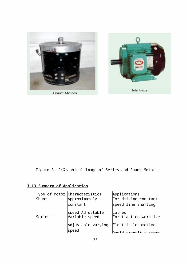
Figure 3.12:Graphical Image of Series and Shunt Motor
3.13 Summary of Application
Type of motor Characteristics ApplicationsShunt Approximately
constant
speed Adjustable
For driving constant speed line shafting
LathesSeries Variable speed
Adjustable varying speed
For traction work i.e.
Electric locomotives
Rapid transit systems33

Cumulative
Compound
Variable speed
Adjustable varying speed
High starting
For intermittent high torque loads
For shears and punches
Elevators
(b) Series Motors
The operating characteristics have been discussed in Art 29.13. These motors
1. Have a relatively huge starting torques.
2. Have good accelerating torque.
3. Have low speed at high loads and dangerously high speed at low loads.
Hence, such motors are used
1. When a large starting torque is required i.e. for driving hoists, cranes, trams etc
2. When the motor can be directly coupled to a load such as a fan whose torque increases with Speed.
3. if constancy of speed is not essential, then, in fact, the decrease of speed with increase of load has the advantage that the power absorbed by the motor does not increase as rapidly as the torque. For instance, when torque is doubled, the power approximately increases by about 50 to 60% only. (∴ Ia ∝T)
4. a series motor should not be used where there is a possibility of the load decreasing to a Very small value.
34

Thus, it should not be used for driving centrifugal pumps or for a belt-drive of any kind.
3.14 Power Stages
Figure 3.14: Power Stages of Motor
3.15 The Controller Box
Brushless motors need complicated electronics. Themanufacturer integrated all the electronics into a blackbox. But due to the unavailability of proper data-sheet, thecontroller wires were identified using some onlineresources, experiments, and exploring the connections in thesystem. The identification diagram is in figure.
35

Figure 3.15: Identification of the controller cables
36

3.16 Wire Diagram of standard controller
Figure 3.16: Wire Diagram of standard controller
37

3.17 The Battery Four 12V, 7.5 Ah Rechargeable batteries were used in seriesto provide 48 Volts to the BLDC motor. These were lead-acidbatteries. The batteries were accommodated inside a rackwhich is made by manually.
38

Figure 3.17: ups Battery
Figure 3.17.2: Battery connection
39

Figure 3.17.3: Battery casing
3.18 Graphical View of Complete Project
40

Figure 3.18 Graphical View of Complete Project
3.19 Battery Specification
Specifications
Chemistry Lead Acid
Voltage 12
41

Capacity 7200 mAh / 7.20 Ah
Rating 86 W hr
Cell 6 cells
Connector F2
Length 5.94 inch / 15.09 cm
Width 2.56 inch / 6.50 cm
Height 3.94 inch / 10.01 cm
Color Black
Weight 5.5 lb / 2.49 Kg
Warranty
3.20 Charger:A very simple yet effective 48v battery charger circuit,utilizing very ordinary components. The circuit is highlyaccurate with it’s over charge cut off features.
42

Figure 3.20: 48V Battery Charger Circuit
As shown in the figure, the main element in the circuit isthe opamp IC 741, which has been arranged as acomparator.Pin#3 which is the inverting input of the IC isreferenced with a fixed voltage of 4.7V throughthe respective zener/resistor network. The other inputis applied with the sensing voltage which is actually thevoltage merged from the supply and the from the battery, inother words the charging voltage which is applied to thebattery for charging. Theresistor network at pin#2 alongwith the preset forms a voltage divider network which isinitially adjusted such that the voltage at this pin staysbelow the voltage level at pin3, which is the referencevoltage set at 4.7v by the zenerdiode. The preset is set insuch a way that the voltage at pin#2 rises above the 4.7mark as soon as the battery voltage rises above 50V or theFill charge threshold level of the battery. The moment thishappens, the output of the op ampGoes low switching OFF the mosfet, and cutting off thevoltage to the battery. Initially as long as the battery
43

voltage and the overall voltage from the 48V supply remainsbelow the full charge threshold level of the battery, theoutput of the opamp stays high and the mosfet us keptswitched ON. This allows the voltage to the battery forcharging, until the above explained threshold is reachedwhich automatically inhibits the battery from further charging.Thermoset can be selected as per the AH rating of the battery.
Chapter-04
4.1 Circuit Diagram of Project
Figure 4.1: circuit diagram
The above circuit can be upgraded into an over charge cutoff, as well as low charge restoring battery chargersystem, for charging 48V batteries. The modificationenables the circuit to switch OFF the battery chargingprocess at the set over charge threshold and restore backthe process when the battery voltage falls below the lowthreshold value. The 10k preset must be adjusted to setthe full charge level while the 22k preset for detectingthe lower threshold of the battery.
44

Figure 4.1.1: circuit diagram
The above design appears to have one problem, it won't beable to detect low battery thresholds, and the design shouldbe rather configured in the following manner:
Figure 4.1.2: circuit diagram
4.2 How to Set Up the Above Circuit45

For setting up procedure, the sample power supply should beconnected across the points where the battery is connected;the mosfet does not require any attention initially. DO NOTconnect the battery while carrying out this procedure. Alsokeep the 22k preset link disconnected initially. Apply thehigher threshold level across the above mentioned points andadjust the 10K preset such that the RED LED just switchesON. Seal the adjusted preset with some glue. Now reconnectthe 22k preset link back into position. Next, reduce thesample voltage to the lower threshold value and adjust the22k preset such that now the green LED just lights up, whileswitching OFF the RED LED.If you find no response from the circuit try using a 100Kpreset instead of the 22k preset. Seal the adjusted presetas above. The setting up of the circuit is over and done.Please note that during actual operations, the above circuitwill remain functional only as long as a battery staysconnected at the shown points, without a battery the circuitwill not detect or respond.
4.3 Throttle Position Sensor (TPS)
A throttle was used to control the speed of the motor.Throttles are generally used in all kinds of e-bikes tocontrol the motor speed. BLDC motor controllers are designedin such a way that a voltage signal (usually not more than5V) controls the minimum to maximum speed of the motor. Athrottle is a specially designed potentiometer where aspecific Vcc (biasing voltage) is provided from the maincontroller unit and outputs voltage corresponding to angleof the throttle, which is supplied to the controller whereit is processed to deliver corresponding speed by the motor.The circuit diagram of a throttle position sensor (TPS) isgiven in
46

In the following sections the behavior of the motorcorresponding to the voltage signal provided by the TPS willbe described in details.
4.4 The Hand-Clutch and Power-KeyA power key is used in the system to turn the whole system‘on’ or ‘off’ manually. This is basically a mechanism to‘short’ two wires that go directly to the controller unitwhen the system is keyed. The hand-clutch is mounted on theleft handle of the rickshaw, along with the traditionalfront-wheel brake-system. It is used to stop the motor at-once. Throttle Position Sensor (TPS) needed, usually in caseof an emergency. The hand clutch will stop the motorirrespective of the throttle position as long as it is heldlike a brake. It will start the motor from the correspondingthrottle position the moment it is left to its originalposition.Fig. shows the connections of the motor wires with thecontroller, TPS, and power key. The hall-sensors of the BLDCmotors and the motor phase cables are also connected in thediagram.
47

Figure 4.4: The Hand-Clutch and Power-Key
4.5 Speed Limiting Cable
There are two Speed Limiting Cables coming out of the CUwhich were connected by default. The speed of the motorincreases significantly if the wires are ‘opened’. The openconditions were not used throughout the system design as thespeed becomes very high and the system becomes unstable forexperimentation.
48

Figure 4.5 Controller box with motor connection
4.6 Speed Control Mechanism of the Existing System
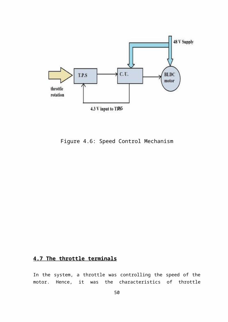
In this system, the speed of the motor is controlled by theThrottle Position Sensor (TPS) unit. The TPS unit suppliescorresponding throttle position voltage to the main BLDCmotor controller unit. The quantitative analysis of thisfact will be discussed in the following section. The mainpower supply is the 48 V Battery which powers the motor andthe controller unit. The CU provides necessary biasing tothe TPS and the TPS outputs voltages according to thethrottle’s angle. This output is fed to the C.U. which thencoerces the motor.
49
25
Figure 4.6: Speed Control Mechanism
4.7 The throttle terminals
In the system, a throttle was controlling the speed of themotor. Hence, it was the characteristics of throttle
50

terminals in the controller which was of interest. It wasexperimentally found that the throttle might be acting as apotentiometer and providing voltage according to rotation.Among the three terminals that went to the CU (Red, Green,and Black); between red and black, the voltage was always4.3V; between Green and Black wires the voltage (output)varied from 0.82 to 3.3V- varying the speed of the motor.The throttle cable was removed and similar voltage wassupplied by an external voltage source, and the results werefound to be similar.
Figure 3.5.4 controller input voltage v/s motor speed plot
If we analyze the plot this figure, we can see that there isa predefined threshold voltage already existing in thepresent system, which is 2.2V. Before reaching 2.2V, themotor never starts; and after 2.2V, the motor speedincreases almost linearly. Data were taken up-to 3.4 voltsas this was the maximum throttle voltage. However, the speedcould be further increased using external battery but thesystem tends to become quite unstable after 3.6/3.7 voltsacross the terminal. It is concluded from the experimentthat the motor speed is almost linear to the controllerinput voltage, which presently comes from the throttle. The
51

target is to provide ‘similar’ pattern of voltage using atorque sensor which will correspond to the “demand” of motorassistance. This profile was most helpful for designing themain control mechanism.
4.8 The shaft speedThe experiment was done in order to understand the nature ofthe shaft speed corresponding to manual pedaling and motorspeed. A sample pedaling speed was introduced intoexperiment, ranging from 150-200rpm. Though the wheels werenot connected in the lab-setup, it was hard to maintain astable speed manually; however a speed of 150-200 rpm wasachieved. The motor speed characteristics with-respect-tocontroller input voltages were found in the precedingexperiment. The total speed of the shaft (motor + manual)was recorded with respect to different input voltages. Itwas found that the shaft rotated at the “higher speed”between the motor and manual input. That means the higherspeed at any instance is followed as the total speed. (Fig.3.9) In the experiment from 2.2-2.7V, the manual speedsustains (however, it feels easier to pedal after 2.2V) upto 2.7V for the current state of pedal speed, and after2.7V, the motor speed is followed.
Figure 3.6: Analysis of shaft speed at motor,pedal andcombined drive
52

From this experiment, it could be concluded that theassistance that comes from the motor comes In-terms-of torque, not speed. That means the speed (rpm) isnot added up when both driving forces (motor and pedal) areactive simultaneously. However, the higher speed ismaintained, and the assistance comes in the form of‘easiness’, that means in-terms-of torque to be applied. Inabove figure, from 2.2 to 2.8 V, the motor is running butthe total shaft speed is tending to follow the pedal speedas it is higher. After the breakeven point of 2.8 V, theshaft speed follows the motor speed.
CHAPTER 5
5.1 Charging Time, Backup time, Battery Type,Charger Comparison between Auto-rickshaw & ElectricBi-cycle
53

Auto Rickshaw Electric bicycleBatteryUsed
4 Pcs 12 Volt45/55/65/75 Amp Battery
Nominal Volt. 12Approx. Dimension (mm)(L×W×H) 304×171×224
4 pcs 12 Volt 7/7.5/8/10Amp battery
Nominal Volt. 12Approx. Dimension (mm)
(L×W×H) 151X65X97
ChargingTime
6 to 8 Hours 1.5 to 2 Hours
Charger
Non Portable PortableHighestSpeed
30 km/h 40 km/h
DistanceCoveredper hour
30 km/h 20 km/h
BatteryConnection
Series Series
54

5.2 Cost Comparison between Auto-rickshaw & ElectricBi-cycle
SL Auto-rickshaw Price Electric Bi-cycle Price1. Nor Electric
(Bangla Chassis)Rickshaw priceApprox. 15000 BDT
25000 Non Geared cyclePrice Approx. 3500BDT
3500
2. 48V BrushlessGeared Motor 500 WPrice : 6000 BDT
6000 48V BrushlessGeared Motor 350 WPrice : 4800 BDT
4200
3. Throttle PositionSensor (TPS)
500 Throttle PositionSensor (TPS)
300
4. Controller Box 750W
1500 Controller Box 500W
1150
5. Speed LimitingCable
500 Speed LimitingCable
250
6. Batteries (12 Volt75 amp 4 Pcs) LargeSize
22500 Batteries (12 Volt7.5 Amp 4 pcs)Small Lead AcidBatteries
4200
7. 48 V Charger NonPortable ChargerBig Size
2000 48 V PortableCharger
500
8. A Meter wherecharge indicator,Head light power,horn on/off systemwith a key
300 Same A Meter wherecharge indicator,Head light power,horn on/off systemwith a key
300
9. A Chain Spoke 500 A Chain Spoke 20010.
2 Hub & 1 Free Ball 1000 1 Hub & 1 FreeBall
550
55

11 Metal Sheet & IronAngle
N/A Metal Sheet & IronAngle & FixingCost
3000
12 Workshop & PaintCost
15000 Workshop &PaintCost
5000
Total Cost AutoRickshaw
74800 Total Cost ForBike
23100
Table 5.3 Cost Estimate
Electric bicycle PriceNon Geared cycle Price Approx. 3500 BDT 3500
48V Brushless Geared Motor 350 W Price :4800 BDT
4200
Throttle Position Sensor (TPS) 300
Controller Box 500 W 1150Speed Limiting Cable 250Batteries (12 Volt 7.5 Amp 4 pcs) SmallLead Acid Batteries
4200
48 V Portable Charger 500
Same A Meter where charge indicator, Headlight power, horn on/off system with akey
300
A Chain Spoke 200
56

1 Hub & 1 Free Ball 550Metal Sheet & Iron Angle & Fixing Cost 3000
Workshop &Paint Cost 5000Total Cost For Bike 23100
5.4 Advantage
Electric bi-cycle user battery bank are much cheaper than the Auto-Rickshaw used battery.
Rickshaw used battery are 48 Volt, 500 W, 65 Amp. Thisvehicle are mainly made for passenger (2/3 personapprox. 150/200 Kg). This battery size is very largeand costly. Bi-cycle used Battery can be used new upsbattery (Lead Acid Battery) or can be used after re-build the damage battery from the ups rejected battery.
In the rickshaw battery charging depend on passenger riding duration & whole day running duration. Daily charge is must for Auto-Rickshaw. Bi-cycle only used for personal usage. If an electric bi-cycle charged 100%. We don’t have to charge next 2/3 days. It’s depends on personal usage of riding duration.
In the bi-cycle, battery & motor are mounted in a safeposition with an upper distance from road than the
57

Auto-Rickshaw. That why electric bi-cycle can be usedin water logging & low/high road easily.
But in the Rickshaw motor is seated very low position in a frame. For this reason it can’t be used in water logging and high/low level road easily.
In the electric cycle motor is mounted in the upper stand of the carrier and in the front side, a modified frame made for mounting batteries. This engineering design help it’s to run over water and high or low level road easily.
Now a day’s auto-rickshaw‘s accident increase 60-70 %. If an auto-rickshaw damaged by accident, its repairing cost is very high for re-run the Rickshaw. But in the electric bi-cycle it happens fewer.
Auto-rickshaw is made for business purpose & it use forbusiness profit. But Electric Bi-cycle used for personal purpose only.
5.5 DisadvantageAuto-Rickshaw usually made for passenger riding. It can loadtwo or three persons at a time. But in the bi-cycle this
58

service can’t be served because in the bi-cycle carrier isalready used for motor mounting.In the Auto-Rickshaw we can carries heavy weight goods but electric bi-cycle we cannot do this.
Environmental BenefitsThe primary premise for government support of electricvehicles has been air quality. The sole legal justificationfor the EV mandate is controlling the pollution. Electricvehicles will not disappoint on this count. But air qualityalone is not sufficient justification to mandate electricvehicles. The single biggest advantage of electric vehiclesis that the electric power is produced in a centralizedlocation where the pollution can be better monitored andcontrolled.
Economic Benefits and Societal impactsThis project involves the implementation and studies of theelectric vehicle. This is of primary importance because ofcurrent world trends. Oil and gasoline is being consumed ata much higher rate than it is being produced. In somecountries gasoline prices are as high as 4 dollars pergallon. This is an outcome that the Bangladesh willeventually face and one that will get worse before it getsbetter.Differences that exist between electric motors and gasolinemotors include the following. Although a gasoline motors canput forth much power with a small engine they are only about30 to 40 percent efficient. Electric motors on the otherhand are around 90 percent efficient. Another important factis that oil takes millions of years to produce and islimited resource electricity can be spontaneously producedand is not considered to be a limited resource. One moreadvantage that electricity has is that it poses very littlethreat to the environment.
59

Safety IssuesThere are many safety issues that in tail this project. Thefirst is that of bicycle safety itself. When one is ridingon a road or traffic filled street unless the bike can keepup with the speed of that street they should ride along theshoulder of the street. It is recommended that when ridingon the shoulder of the street that one rides against theflow of traffic. If something should occur there is morereaction time for the bicyclist. One can also be aware ofwhether drivers are aware of your presents. Also when ridinga bicycle and even more important when riding an electricbicycle, a bicycle helmet should be worn. And when riding oncity or country roads always obey the traffic laws.Another safety concern of this electric bicycle is that itshould not be driven in the rain. If the motor controllercircuit gets wet it may fry the MOSFET transistors. Althougha protective cover is placed over the circuit, in heavyrainwater could still make its way up into the circuit. Itis also recommended that the electric bicycle be not riddenthrough puddles or wet terrain because of the tires tendencyof throwing water up onto the bike.
60

When servicing the bicycle only authorized personnel shoulddo so. Since the motor takes a 20 amp current when thebattery is fully charged there is a risk of electrocution.Small children should not be allowed to ride the bike. It isour recommendation that the age requirement be 12 years andolder in order to operate the bicycle.
5.6 DiscussionThe electric bicycle project has provided an opportunity tograsp the full scope of what it means to Design a product.This opportunity allowed an initial idea/goal to be realized
61
in a team environment. The idea developed as research andvarious other information on the topic was obtained. Theproject evolved and changed as the team limitations andfinancial constraints were realized. Due to a lack offunding, the initial design of an electric go-cart wasdownsized to the current project, the electric assistedbicycle. The initial design, of the electric assistedbicycle, carried along with it constraints that had to beworked around. The constraints were mainly financial innature. They represent pieces of equipment in the designthat had to be carried over from other semesters. Theconstraints on the equipment consisted of the battery,motor, and the bicycle frame. The motor bicyclerelationship could not be altered, mainly due to the type ofmounting on the motor. These constraints limited, but didnot totally restrict the team’s ability to design a “new”system. Once all constraints were known, the goals for thedesign were clearly identified. The goals were dividedamong the team members. In order to meet the deadline forthe final project, progress was monitored weekly andindividual goals were readjusted as needed. Withcommunication between the team, and hard work, the finalobjective was obtained. The design project provided theteam with valuable experience in design and teamwork. Itallowed the team members to develop skills that will beuseful in future endeavors.
62
Bibliography:
1. B.L Thereja & A.K Thereja – A Book of Electrical Technology, volume-II, Page no:-996-1022
2. James R Turner—Electric bicycle and methods US 6296072 B1
3. Ronald Holland –Electric bicycle with jackshaft assembly US 7461714B2
4. Energy consumption by Battery operated auto rickshaw- DAFFODIL INTERNATIONAL UNIVERSITY JOURNAL OF SCIENCE AND TECHNOLOGY, VOLUME 8, ISSUE 2, JULY 2013
5. Mohan, D. D. (2007), “Three-wheeled Scooter Taxi: Problems and Solutions for an Efficient Mode of Transport”, Institute of Urban Transport, New Delhi-110011, p. 11.
63