
NFPA 55 - Standard for the Storage, Use, and Handling of ...
96
Copyright NFPA N FPA 55 Standard for the Storage, Use, and Handling of Compressed Gases and Cryogenic Fluids in Portable and Stationary Containers, Cylinders, and Tanks 2005 Edition Copyright © 2005, National Fire Protection Association, All Rights Reserved This edition of NFPA 55, Standard for the Storage, Use, and Handling of Compressed Gases and Cryogenic Fluids in Portable and Stationary Containers, Cylinders, and Tanks , was prepared by the Technical Committee on Industrial and Medical Gases and acted on by NFPA at its November Association Technical Meeting held November 13–17, 2004, in Miami Beach, FL. It was issued by the Standards Council on January 14, 2005, with an effective date of February 7, 2005, and supersedes all previous editions. This edition of NFPA 55 was approved as an American National Standard on February 7, 2005. Origin and Development of NFPA 55 NFPA 55 was developed by the Industrial and Medical Gases Committee in recognition of the need to provide information on the use of cylinder gases in one standard. The Compressed Gas Association assisted the project by submitting a draft that was used as t he framework for the standard. NFPA 55 supersedes NFPA 43C, Code for the Storage of Gaseous Oxidizing Materials , which was developed by the Committee on Hazardous Chemicals and transferred to the Industrial and Medical Gases Committee. The committee believed that one standard covering s torage of all gas cylinders was needed and, with the new NFPA 55, the need for NFPA 43C no longer existed. Since this standard was introduced in 1993, it has been widely used and accepted by users of different types of gases as a single source covering requirements for installation and usage of gases in portable cylinders. The 1998 edition clarified many requir ements and provided additional advisory information to assist the users of the standard. Editorial changes were also incorporated for clarity.
-
Upload
khangminh22 -
Category
Documents
-
view
2 -
download
0
Transcript of NFPA 55 - Standard for the Storage, Use, and Handling of ...
Copyright NFPA
NFPA 55 Standard for the
Storage, Use, and Handling of Compressed Gases and
Cryogenic Fluids in Portable and Stationary Containers,
Cylinders, and Tanks
2005 Edition
Copyright © 2005, National Fire Protection Association, All Rights Reserved
This edition of NFPA 55, Standard for the Storage, Use, and Handling of Compressed Gases and Cryogenic Fluids in Portable and Stationary Containers, Cylinders, and Tanks, was prepared by the Technical Committee on Industrial and Medical Gases and acted on by NFPA at its November Association Technical Meeting held November 13–17, 2004, in Miami Beach, FL. It was issued by the Standards Council on January 14, 2005, with an effective date of February 7, 2005, and supersedes all previous editions.
This edition of NFPA 55 was approved as an American National Standard on February 7, 2005.
Origin and Development of NFPA 55
NFPA 55 was developed by the Industrial and Medical Gases Committee in recognition of the need to provide information on the use of cylinder gases in one standard. The Compressed Gas Association assisted the project by submitting a draft that was used as the framework for the standard.
NFPA 55 supersedes NFPA 43C, Code for the Storage of Gaseous Oxidizing Materials, which was developed by the Committee on Hazardous Chemicals and transferred to the Industrial and Medical Gases Committee. The committee believed that one standard covering storage of all gas cylinders was needed and, with the new NFPA 55, the need for NFPA 43C no longer existed.
Since this standard was introduced in 1993, it has been widely used and accepted by users of different types of gases as a single source covering requirements for installation and usage of gases in portable cylinders. The 1998 edition clarified many requirements and provided additional advisory information to assist the users of the standard. Editorial changes were also incorporated for clarity.

Copyright NFPA
The 2003 edition of NFPA 55 was a complete revision of the document that significantly expanded the document scope and introduced requirements for areas not addressed in previous editions. For example, the 1998 edition covered only compressed and liquefied gases in portable cylinders and only at consumer (user) locations; the 2003 edition covered the use of compressed and liquefied gases in portable and stationary containers and at manufacturer sites and consumer sites. This expansion to manufacturer sites took a large portion of gas usage that was outside the scope of NFPA 55 and placed it under NFPA 55.
There were many new subjects and requirements in the 2003 edition, including the following:
(1) Requirements for cryogenic fluids
(2) Use of the concept of control areas for defining storage amounts and requirements
(3) An expanded classification scheme to cover a greater range of gaseous materials
(4) Specifications for a Hazardous Materials Management Plan
(5) Requirements for treating waste gases
(6) More detailed requirements in many of the areas than the 1998 edition of NFPA 55 covered
The document was also restructured to comply with the Manual of Style for NFPA Technical Committee Documents.
The 2005 edition of NFPA 55 is a complete revision of the document.
The following are some of the significant changes to the document:
(1) Incorporation of the requirements of NFPA 50, Standard for Bulk Oxygen Systems at Consumer Sites, into Chapter 9
(2) Incorporation of the requirements of NFPA 50A, Standard for Gaseous Hydrogen Systems at Consumer Sites, into Chapter 10
(3) Incorporation of NFPA 50B, Standard for Liquefied Hydrogen Systems at Consumer Sites, into Chapter 11
(4) Clarification of threshold storage requirements in Chapters 6 and 7
(5) Clarification of the separation distance tables formerly in NFPA 50, 50A, and 50B and now in Chapters 9–11
(6) Schematic drawings added to annex material to illustrate system siting requirements in Chapters 9 and 11
Technical Committee on Industrial and Medical Gases
Michael W. St. Clair, Chair The Ohio State University, OH [U]
Rep. NFPA Industrial Fire Protection Section

Copyright NFPA
William J. Satterfield, III, Secretary Hydrogen Safety, LLC/Rode & Associates, LLC, RI [SE]
John Anicello, Airgas, Incorporated, CA [IM] Rep. Compressed Gas Association
William H. Barlen, Barlen and Associates, Inc., CT [M] Rep. Airgas, Inc.
Keith Ferrari, Praxair, NC [M]
Rick Ginn, Wright Brothers, Inc., OH [M] Rep. National Welding Supply Association
Gary W. Howard, Stuart Energy Systems, Canada [M]
Ronald Keefer, Menlo Park Fire Protection District, CA [E]
Anthony J. McErlean, Messer Group (MG Industries), PA [IM] Rep. Compressed Gas Association
George Mills, MM EC, Ltd., IL [U] Rep. American Society for Healthcare Engineering
David Namyst, Intel Corporation, CA [M]
Robert R. Nii, Bechtel BWXT Idaho, LLC, ID [U]
Peter W. Steiner, Air Products and Chemicals, Inc., PA [IM] Rep. Compressed Gas Association
Gary F. Trojak, Chlorine Institute Incorporated, VA [M] Rep. The Chlorine Institute
Randolph Viscomi, ARC Specialty Products Corporation, NJ [IM]
Robert A. Zeman, Underwriters Laboratories Inc., IL [RT]
Alternates
Leonard A. Farello, Intel Corporation, NM [M] (Alt. to D. Namyst)
Larry L. Fluer, Fluer, Incorporated, CA [IM] (Alt. to A. J. McErlean)

Copyright NFPA
Eugene Y. Ngai, Air Products and Chemicals, Inc., PA [IM] (Alt. to P. W. Steiner)
Jeffrey M. Shapiro, International Code Consultants, TX [M] (Alt. to G. F. Trojak)
Roger A. Smith, Compressed Gas Association, Inc., VA [IM] (Alt. to J. Anicello)
Edgar WolffKlammer, Underwriters Laboratories Inc., IL [RT] (Alt. to R. A. Zeman)
Nonvoting
Joanne E. Slattery, U.S. Department of Labor, DC [E] Rep. Occupational Safety and Health Administration
Charles B. Henrici, Elk Grove Village, IL [SE] (Member Emeritus)
Carl H. Rivkin, NFPA Staff Liaison
This list represents the membership at the time the Committee was balloted on the final text of this edition. Since that time, changes in the membership may have occurred. A key to classifications is found at the back of the document.
NOTE: Membership on a committee shall not in and of itself constitute an endorsement of the Association or any document developed by the committee on which the member serves.
Committee Scope: This Committee shall have primary responsibility for documents on the storage, transfer, and use of industrial gases. Included are the storage and handling of such gases in their gaseous or liquid phases; the installation of associated storage, piping, and distribution equipment; and operating practices. The Committee also has a technical responsibility for contributions in the same areas for medical gases and clean rooms.
NFPA 55 Standard for the
Storage, Use, and Handling of Compressed Gases and Cryogenic Fluids in Portable and Stationary Containers, Cylinders, and Tanks
2005 Edition
IMPORTANT NOTE: This NFPA document is made available for use subject to important notices and legal disclaimers. These notices and disclaimers appear in all publications containing this document and may be found under the heading “Important Notices and Disclaimers Concerning NFPA Documents.” They can also be obtained on request from NFPA or viewed at www.nfpa.org/disclaimers.
NOTICE: An asterisk (*) following the number or letter designating a paragraph indicates
Copyright NFPA
that explanatory material on the paragraph can be found in Annex A.
A reference in brackets [ ] following a section or paragraph indicates material that has been extracted from another NFPA document. As an aid to the user, the complete title and edition of the source documents for mandatory extracts are given in Chapter 2 and those for nonmandatory extracts are given in Annex D. Editorial changes to extracted material consist of revising references to an appropriate division in this document or the inclusion of the document number with the division number when the reference is to the original document. Requests for interpretations or revisions of extracted text shall be sent to the technical committee responsible for the source document.
Information on referenced publications can be found in Chapter 2 and Annex D.
Chapter 1 Administration
1.1 Scope.
1.1.1 Applicability. This standard shall apply to the installation, storage, use, and handling of compressed gases and cryogenic fluids in portable and stationary containers, cylinders, equipment, and tanks in all occupancies.
1.1.2 Exemptions. This standard shall not apply to the following:
(1)* Offsite transportation of materials covered by this standard
(2) Storage, use, and handling of radioactive gases in accordance with NFPA 801, Standard for Fire Protection for Facilities Handling Radioactive Materials
(3) Storage, use, and handling of medical compressed gases at health care facilities in accordance with NFPA 99, Standard for Health Care Facilities
(4)* Except for Chapter 9, storage, use, and handling of bulk oxygen in medical gas systems at health care facilities
(5) Systems consisting of cylinders of oxygen and cylinders of fuel gas used for welding and cutting in accordance with NFPA 51, Standard for the Design and Installation of Oxygen–Fuel Gas Systems for Welding, Cutting, and Allied Processes
(6) Acetylene cylinders in acetylene cylinder charging plants in accordance with NFPA 51A, Standard for Acetylene Cylinder Charging Plants
(7) Ethylene oxide containers stored, handled, or used for sterilization and fumigation in accordance with NFPA 560, Standard for the Storage, Handling, and Use of Ethylene Oxide for Sterilization and Fumigation
(8)* Flammable gases used as a vehicle fuel when stored on a vehicle
(9)* Storage, use, and handling of liquefied and nonliquefied compressed gases in laboratory work areas that are in accordance with NFPA 45, Standard on Fire Protection for Laboratories Using Chemicals
(10) Storage, use, and handling of liquefied petroleum gases in accordance with NFPA 58,

Copyright NFPA
Liquefied Petroleum Gas Code
(11) Storage, use, and handling of gases within closedcycle refrigeration systems complying with the mechanical code
(12) Liquefied natural gas (LNG) storage at utility plants under NFPA 59A, Standard for the Production, Storage, and Handling of Liquefied Natural Gas (LNG)
(13) LNG handled as a vehicle fuel under NFPA 57, Liquefied Natural Gas (LNG) Vehicular Fuel Systems Code
(14) Compressed natural gas (CNG) handled as a vehicle fuel under NFPA 52, Compressed Natural Gas (CNG) Vehicular Fuel Systems Code
1.2* Purpose.
The purpose of this standard shall be to provide fundamental safeguards for the installation, storage, use, and handling of compressed gases and cryogenic fluids in portable and stationary containers, cylinders, and tanks.
1.3 Application.
The requirements in this standard shall apply to users, producers, distributors, and others who are involved with the storage, use, or handling of compressed gases or cryogenic fluids.
1.4 Retroactivity.
The provisions of this standard reflect a consensus of what is necessary to provide an acceptable degree of protection from the hazards addressed in this standard at the time the standard was issued.
1.4.1 Unless otherwise specified, the provisions of this standard shall not apply to facilities, equipment, structures, or installations that existed or were approved for construction or installation prior to the effective date of the standard. Where specified, the provisions of this standard shall be retroactive.
1.4.2 In those cases where the authority having jurisdiction determines that the existing situation presents an unacceptable degree of risk, the authority having jurisdiction shall be permitted to apply retroactively any portions of this standard deemed appropriate.
1.4.3 The retroactive requirements of this standard shall be permitted to be modified if their application clearly would be impractical in the judgment of the authority having jurisdiction, and only where it is clearly evident that a reasonable degree of safety is provided.
1.5 Equivalency.
Nothing in this standard is intended to prevent the use of systems, methods, or devices of equivalent or superior quality, strength, fire resistance, effectiveness, durability, and safety over those prescribed by this standard.
1.5.1 Technical documentation shall be submitted to the authority having jurisdiction to demonstrate equivalency.

Copyright NFPA
1.5.2 The system, method, or device shall be approved for the intended purpose by the authority having jurisdiction.
1.6 Units and Formulas.
International (SI) units shall be used as the standard unit of measure. SI units shall be followed by inchpound units in parentheses.
Chapter 2 Referenced Publications
2.1 General.
The documents or portions thereof listed in this chapter are referenced within this standard and shall be considered part of the requirements of this document.
2.2 NFPA Publications.
National Fire Protection Association, 1 Batterymarch Park, Quincy, MA 021697471.
NFPA 1, Uniform Fire Code™, 2003 edition.
NFPA 13, Standard for the Installation of Sprinkler Systems, 2002 edition.
NFPA 45, Standard on Fire Protection for Laboratories Using Chemicals, 2004 edition.
NFPA 51, Standard for the Design and Installation of Oxygen–Fuel Gas Systems for Welding, Cutting, and Allied Processes, 2002 edition.
NFPA 51A, Standard for Acetylene Cylinder Charging Plants, 2001 edition.
NFPA 52, Compressed Natural Gas (CNG) Vehicular Fuel Systems Code, 2002 edition.
NFPA 57, Liquefied Natural Gas (LNG) Vehicular Fuel Systems Code, 2002 edition.
NFPA 58, Liquefied Petroleum Gas Code, 2004 edition.
NFPA 59A, Standard for the Production, Storage, and Handling of Liquefied Natural Gas (LNG), 2001 edition.
NFPA 69, Standard on Explosion Prevention Systems, 2002 edition.
NFPA 70, National Electrical Code ® , 2005 edition.
NFPA 72 ® , National Fire Alarm Code ® , 2002 edition.
NFPA 99, Standard for Health Care Facilities, 2005 edition.
NFPA 110, Standard for Emergency and Standby Power Systems, 2002 edition.
NFPA 496, Standard for Purged and Pressurized Enclosures for Electrical Equipment, 2003 edition.
NFPA 560, Standard for the Storage, Handling, and Use of Ethylene Oxide for Sterilization and Fumigation, 2002 edition.

Copyright NFPA
NFPA 704, Standard System for the Identification of the Hazards of Materials for Emergency Response, 2001 edition.
NFPA 801, Standard for Fire Protection for Facilities Handling Radioactive Materials, 2003 edition.
NFPA 5000 ® , Building Construction and Safety Code ® , 2003 edition.
2.3 Other Publications.
2.3.1 ASME Publications.
American Society of Mechanical Engineers, Three Park Avenue, New York, NY 100165990.
ASME A13.1, Scheme for the Identification of Piping Systems, 1996.
ASME B31.3, Process Piping, 2002.
ASME International, Boiler and Pressure Vessel Code, “Rules for the Construction of Unfired Pressure Vessels,” Section VIII, 2001.
2.3.2 ASTM Publications.
American Society for Testing and Materials, 100 Barr Harbor Drive, West Conshohocken, PA 194282959.
ASTM E 68101, Standard Test Method for Concentration Limits of Flammability of Chemicals (Vapors and Gases), 2002.
ASTM E 1529, Determining Effects of Large Hydrocarbon Pool Fire on Structural Members and Assemblies, 2003.
2.3.3 CGA Publications.
Compressed Gas Association, 4221 Walney Road, 5th floor, Chantilly, VA 201512923.
CGA C7, Guide to the Preparation of Precautionary Labeling and Marking of Compressed Gas Containers, 2000.
CGA G4.1, Cleaning Equipment for Oxygen Service, 1996.
CGA G5.5, Hydrogen Vent Systems, 1996.
CGA P1, Safe Handling of Compressed Gases in Containers, 2000.
CGA P18, Standard for Bulk Inert Gas Systems at Consumer Sites, 1992.
CGA P20, Standard for the Classification of Toxic Gas Mixtures, 1995.
CGA P23, Standard for Categorizing Gas Mixtures Containing Flammable and Nonflammable Components, 1995.
CGA P32, Safe Storage and Handling of Silane and Silane Mixtures, 2000.
CGA S1.1, Pressure Relief Device Standards – Part 1 – Cylinders for Compressed Gases,

Copyright NFPA
2001.
CGA S1.2, Pressure Relief Device Standards – Part 2 – Cargo and Portable Tanks for Compressed Gases, 1995.
CGA S1.3, Pressure Relief Device Standards – Part 3 – Stationary Storage Containers for Compressed Gases, 1995.
2.3.4* CTC Publication.
Canadian Transport Commission, Queen's Printer, Ottawa, Ontario, Canada. (Available from the Canadian Communications Group Publication Centre, Ordering Department, Ottawa, Canada K1A 0S9.)
Transportation of Dangerous Goods Regulations.
2.3.5 IAPMO Publication.
International Association of Plumbing and Mechanical Officials, 5001 E. Philadelphia Street, Ontario, CA 91761.
Uniform Mechanical Code, 2003 edition.
2.3.6 ISO Publications.
International Organization for Standardization Publications, 1 rue de Varembé, Case Postale 56, CH1211 Geneve 20, Switzerland.
ISO 10156, Gases and gas mixtures – Determination of fire potential and oxidizing ability for the selection of cylinder valve outlets, 1996.
ISO 10298, Determination of toxicity of a gas or gas mixture, 1995.
2.3.7 U.S. Government Publications.
U. S. Government Printing Office, Washington, DC 20402.
Title 29, Code of Federal Regulations, Part 1910.1000.
Title 49, Code of Federal Regulations, Part 173.
Chapter 3 Definitions
3.1 General.
The definitions contained in this chapter shall apply to the terms used in this standard. Where terms are not defined in this chapter or within another chapter, they shall be defined using their ordinarily accepted meanings within the context in which they are used. MerriamWebster's Collegiate Dictionary, 11th edition, shall be the source for the ordinarily accepted meaning.
3.2 NFPA Official Definitions.

Copyright NFPA
3.2.1* Approved. Acceptable to the authority having jurisdiction.
3.2.2* Authority Having Jurisdiction (AHJ). An organization, office, or individual responsible for enforcing the requirements of a code or standard, or for approving equipment, materials, an installation, or a procedure.
3.2.3 Labeled. Equipment or materials to which has been attached a label, symbol, or other identifying mark of an organization that is acceptable to the authority having jurisdiction and concerned with product evaluation, that maintains periodic inspection of production of labeled equipment or materials, and by whose labeling the manufacturer indicates compliance with appropriate standards or performance in a specified manner.
3.2.4* Listed. Equipment, materials, or services included in a list published by an organization that is acceptable to the authority having jurisdiction and concerned with evaluation of products or services, that maintains periodic inspection of production of listed equipment or materials or periodic evaluation of services, and whose listing states that either the equipment, material, or service meets appropriate designated standards or has been tested and found suitable for a specified purpose.
3.2.5 Shall. Indicates a mandatory requirement.
3.2.6 Should. Indicates a recommendation or that which is advised but not required.
3.2.7 Standard. A document, the main text of which contains only mandatory provisions using the word “shall” to indicate requirements and which is in a form generally suitable for mandatory reference by another standard or code or for adoption into law. Nonmandatory provisions shall be located in an appendix or annex, footnote, or fineprint note and are not to be considered a part of the requirements of a standard.
3.3 General Definitions.
3.3.1* Absolute Pressure. Pressure based on a zero reference point, the perfect vacuum.
3.3.2 Area.
3.3.2.1 Control Area. A designated area, either indoors or outdoors, within which limited quantities of hazardous materials are allowed to be stored, used, handled, or dispensed.
3.3.2.2 Indoor Area. An area that is within a building or structure having overhead cover, other than a structure qualifying as “weather protection” in accordance with 6.5.2. (See also 3.3.2.3, Outdoor Area.)
3.3.2.3 Outdoor Area. An area that is not an indoor area.
3.3.3 ASME. American Society of Mechanical Engineers. [58, 2004]
3.3.4 ASTM. American Society for Testing and Materials.
3.3.5 Building. Any structure used or intended for supporting or sheltering any use or occupancy. [101, 2003]
3.3.6 Building Code. The building or construction code adopted by the jurisdiction.

Copyright NFPA
3.3.7 Bulk Hydrogen Compressed Gas System. An assembly of equipment, consisting of but not limited to, storage containers, pressure regulators, pressure relief devices, vaporizers, manifolds, and piping, with a storage capacity of more than 400 ft 3 (scf) (11 m 3 ) of compressed hydrogen gas including unconnected reserves on hand at the site. The bulk system terminates at the point where the gas supply, at service pressure, first enters the supply line. The containers are either stationary or movable, and the source gas is stored as a compressed gas.
3.3.8 Bulk Inert Gas System. An assembly of equipment, consisting of but not limited to, storage containers, pressure regulators, pressure relief devices, vaporizers, manifolds, and piping, with a storage capacity of more than 20,000 ft 3 (scf) (566 m 3 ) of inert gas including unconnected reserves on hand at the site. The bulk system terminates at the point where the gas supply, at service pressure, first enters the supply line. The containers are either stationary or movable, and the source gas is stored as a compressed gas or cryogenic fluid.
3.3.9 Bulk Liquefied Hydrogen Gas System. An assembly of equipment, consisting of but not limited to, storage containers, pressure regulators, pressure relief devices, vaporizers, manifolds, and piping, with a storage capacity of more than 39.7 gal (150 L) of liquefied hydrogen including unconnected reserves on hand at the site. The bulk system terminates at the point where the gas supply, at service pressure, first enters the supply line. The containers are either stationary or movable, and the source gas is stored as a cryogenic fluid.
3.3.10 Bulk Oxygen System. An assembly of equipment, such as oxygen storage containers, pressure regulators, pressure relief devices, vaporizers, manifolds, and interconnecting piping, with a storage capacity of more than 20,000 ft 3 (scf) (566 m 3 ) of oxygen including unconnected reserves on hand at the site. The bulk oxygen system terminates at the point where oxygen at service pressure first enters the supply line. The oxygen containers are either stationary or movable, and the oxygen is stored as a compressed gas or cryogenic fluid.
3.3.11 CFR. The Code of Federal Regulations of the United States Government. [1, 2003]
3.3.12 CGA. Compressed Gas Association.
3.3.13 Combustible Liquid. A liquid having a closedcup flash point at or above 100°F (37.8°C), subdivided as follows: (a) Class II liquids include those having a flash point at or above 100°F (37.8°C) and below 140°F (60°C); (b) Class IIIA liquids include those having a flash point at or above 140°F (60°C) and below 200°F (93.4°C); (c) Class IIIB liquids include those having a flash point at or above 200°F (93.4°C).
3.3.14 Container. A vessel, such as a cylinder, portable tank, or stationary tank, that varies in shape, size, and material of construction.
3.3.14.1 Compressed Gas Container. A pressure vessel designed to hold compressed gas at an absolute pressure greater than 1 atmosphere at 20°C (68°F) that includes cylinders, containers, and tanks.
3.3.15 Court. An open, uncovered, unoccupied space, unobstructed to the sky, bounded on three or more sides by exterior building walls. [101, 2003]

Copyright NFPA
3.3.15.1 Enclosed Court. A court bounded on all sides by the exterior walls of a building or by the exterior walls and lot lines on which walls are permitted. [5000, 2003]
3.3.16 Cryogenic Fluid. A fluid with a boiling point lower than 90°C (130°F) at an absolute pressure of 101.325 kPa (14.7 psia).
3.3.17 Cylinder. A pressure vessel designed for pressures higher than 276 kPa (40 psia) and having a circular crosssection. It does not include a portable tank, multiunit tank car tank, cargo tank, or tank car.
3.3.18* Cylinder Pack. An arrangement of cylinders into a cluster where the cylinders are confined into a grouping or arrangement with a strapping or frame system and connections are made to a common manifold. The frame system is allowed to be on skids or wheels to permit movement.
3.3.19 Cylinder Containment Vessel. A gastight recovery vessel designed so that a leaking compressed gas container can be placed within its confines, thereby encapsulating the leaking container.
3.3.20 Detached Building. A separate building that is separated from other structures or uses as required by NFPA 5000 for a freestanding structure. [5000, 2003]
3.3.21 Distributor. A business engaged in the sale or resale, or both of compressed gases or cryogenic fluids, or both.
3.3.22 DOT. U.S. Department of Transportation. [57, 2002]
3.3.23 Emergency Shutoff Valve. A designated valve designed to shut off the flow of gases or liquids.
3.3.23.1 Automatic Emergency Shutoff Valve. A designated failsafe automatic closing valve designed to shut off the flow of gases or liquids that is initiated by a control system where the control system is activated by either manual or automatic means.
3.3.23.2 Manual Emergency Shutoff Valve. A designated valve designed to shut off the flow of gases or liquids that is manually operated.
3.3.24 Excess Flow Control. A failsafe system or approved means designed to shut off flow due to a rupture in pressurized piping systems.
3.3.25* Exhausted Enclosure. An appliance or piece of equipment that consists of a top, a back, and two sides that provides a means of local exhaust for capturing gases, fumes, vapors, and mists.
3.3.26* Explosion Control. A means of either preventing an explosion through the use of explosion suppression, fuel reduction or oxidant reduction systems or a means to prevent the structural collapse of a building in the event of an explosion through the use of deflagration venting, barricades or related construction methods.
3.3.27* Flammable Liquid (Class I). Any liquid having a closedcup flash point not exceeding 37.8°C (100°F).
Copyright NFPA
3.3.28 Gallon. A standard U.S. gallon.
3.3.29 Gas.
3.3.29.1* Compressed Gas. A material, or mixture of materials, that (1) is a gas at 20°C (68°F) or less at an absolute pressure of 101.325 kPa (14.696 psia) and (2) that has a boiling point of 20°C (68°F) or less at an absolute pressure of 101.325 kPa (14.7 psia) and that is liquefied, nonliquefied, or in solution, except those gases that have no other health or physical hazard properties are not considered to be compressed gases until the pressure in the packaging exceeds an absolute pressure of 280 kPa (40.6 psia) at 20°C (68°F).
3.3.29.2 Corrosive Gas. A gas that causes visible destruction of or irreversible alterations in living tissue by chemical action at the site of contact.
3.3.29.3 Flammable Gas. A material that is a gas at 20°C (68°F) or less at an absolute pressure of 101.325 kPa (14.7 psia), that is ignitable at an absolute pressure of 101.325 kPa (14.7 psia) when in a mixture of 13 percent or less by volume with air, or that has a flammable range at an absolute pressure of 101.325 kPa (14.7 psia) with air of at least 12 percent, regardless of the lower limit.
3.3.29.4 Flammable Liquefied Gas. A liquefied compressed gas that, when under a charged pressure, is partially liquid at a temperature of 20°C (68°F) and is flammable.
3.3.29.5 Highly Toxic Gas. A chemical that has a median lethal concentration (LC 50 ) in air of 200 ppm by volume or less of gas or vapor, or 2 mg/L or less of mist, fume, or dust, when administered by continuous inhalation for 1 hour (or less if death occurs within 1 hour) to albino rats weighing between 200 g and 300 g (0.44 lb and 0.66 lb) each.
3.3.29.6 Inert Gas. A nonreactive, nonflammable, noncorrosive gas such as argon, helium, krypton, neon, nitrogen, and xenon.
3.3.29.7 Irritant Gas. A chemical that is not corrosive, but that causes a reversible inflammatory effect on living tissue by chemical action at the site of contact. A chemical is a skin irritant if, when tested on the intact skin of albino rabbits by the methods of 16 CFR 1500.41, for an exposure of 4 or more hours or by other appropriate techniques, it results in an empirical score of 5 or more. A chemical is classified as an eye irritant if so determined under the procedure listed in 16 CFR 1500.42, or other appropriate techniques.
3.3.29.8 Nonflammable Gas. A gas that does not meet the definition of a flammable gas.
3.3.29.9* Other Gas. A gas that is not a corrosive gas, flammable gas, highly toxic gas, oxidizing gas, pyrophoric gas, toxic gas, or unstable reactive gas with a hazard rating of Class 2, Class 3, or Class 4 gas.
3.3.29.10 Oxidizing Gas. A gas that can support and accelerate combustion of other materials.
3.3.29.11 Pyrophoric Gas. A gas with an autoignition temperature in air at or below 54.4°C (130°F).
3.3.29.12 Toxic Gas. A gas with a median lethal concentration (LC 50 ) in air of more than

Copyright NFPA
200 ppm, but not more than 2000 ppm by volume of gas or vapor, or more than 2 mg/L, but not more than 20 mg/L of mist, fume, or dust, when administered by continuous inhalation for 1 hour (or less if death occurs within 1 hour) to albino rats weighing between 200 g and 300 g (0.44 lb and 0.66 lb) each.
3.3.29.13* Unstable Reactive Gas. A gas that, in the pure state or as commercially produced, will vigorously polymerize, decompose, or condense, become selfreactive, or otherwise undergo a violent chemical change under conditions of shock, pressure, or temperature.
3.3.29.13.1 Class 2 Unstable Reactive Gas. Materials that readily undergo violent chemical change at elevated temperatures and pressures.
3.3.29.13.2 Class 3 Unstable Reactive Gas. Materials that in themselves are capable of detonation or explosive decomposition or explosive reaction, but that require a strong initiating source or that must be heated under confinement before initiation.
3.3.29.13.3 Class 4 Unstable Reactive Gas. Materials that in themselves are readily capable of detonation or explosive decomposition or explosive reaction at normal temperatures and pressures.
3.3.30* Gas Cabinet. A fully enclosed, noncombustible enclosure used to provide an isolated environment for compressed gas cylinders in storage and use. [5000, 2003]
3.3.31 Gas Manufacturer/Producer. A business that produces compressed gases or cryogenic fluids, or both, or fills portable or stationary gas containers, cylinders, or tanks.
3.3.32* Gas Room. A separately ventilated, fully enclosed room in which only compressed gases, cryogenic fluids, associated equipment and supplies are stored or used.
3.3.33* Gaseous Hydrogen System. A system in which the hydrogen is delivered, stored, and discharged in the gaseous form to a piping system. The gaseous hydrogen system terminates at the point where hydrogen at service pressure first enters the distribution piping.
3.3.34 Handling. The deliberate movement of material in containers by any means to a point of storage or use.
3.3.35* Hazard Rating. The numerical rating of the health, flammability, and selfreactivity, and other hazards of the material, including its reaction with water, specified in NFPA 704, Standard System for the Identification of the Hazards of Materials for Emergency Response.
3.3.36* Immediately Dangerous to Life and Health (IDLH). A concentration of airborne contaminants, normally expressed in parts per million (ppm) or milligrams per cubic meter, that represents the maximum level from which one could escape within 30 minutes without any escapeimpairing symptoms or irreversible health effects.
3.3.37* ISO Module. An assembly of tanks or tubular cylinders permanently mounted in a frame conforming to International Organization for Standardization (ISO) requirements.
3.3.38 Limit.
Copyright NFPA
3.3.38.1 Ceiling Limit. The maximum concentration of an airborne contaminant to which a person might be exposed. The ceiling limits utilized are those published in 29 CFR 1910.1000. [5000, 2003]
3.3.38.2* Permissible Exposure Limit (PEL). The maximum permitted 8hour, timeweighted average concentration of an airborne contaminant.
3.3.38.3* ShortTerm Exposure Limit (STEL). The concentration to which it is believed that workers can be exposed continuously for a short period of time without suffering from irritation, chronic or irreversible tissue damage, or narcosis of a degree sufficient to increase the likelihood of accidental injury, impairment of selfrescue, or the material reduction of work efficiency, without exceeding the daily permissible exposure limit (PEL).
3.3.39 Limited Combustible. A building construction material not complying with the definition of noncombustible material that, in the form in which it is used, has a potential heat value not exceeding 3500 Btu/lb (8141 kJ/kg), where tested in accordance with NFPA 259, Standard Test Method for Potential Heat of Building Materials, and complies with (a) or (b): (a) materials having a structural base of noncombustible material, with a surfacing not exceeding a thickness of in. (3.2 mm) that has a flame spread index not greater than 50; and (b) materials, in the form and thickness used, other than as described in (a), having neither a flame spread index greater than 25 nor evidence of continued progressive combustion and of such composition that surfaces that would be exposed by cutting through the material on any plane would have neither a flame spread index greater than 25 nor evidence of continued progressive combustion. (Materials subject to increase in combustibility or flame spread index beyond the limits herein established through the effects of age, moisture, or other atmospheric condition shall be considered combustible. [220, 1999]
3.3.40* Liquefied Hydrogen System. A system into which liquefied hydrogen is delivered and stored and from which it is discharged in the liquid or gaseous form to a piping system. The system originates at the storage container fill connection and terminates at the point where hydrogen at service pressure first enters the supply line.
3.3.41 Material Safety Data Sheet (MSDS). Written or printed material concerning a hazardous material that is prepared in accordance with the provisions of 29 CFR 1910.1200.
3.3.42 Maximum Allowable Quantity Per Control Area (MAQ). A threshold quantity of hazardous material in a specific hazard class that once exceeded requires the application of additional administrative procedures, construction features or engineering controls.
3.3.43 Mechanical Code. The mechanical or mechanical construction code adopted by the jurisdiction.
3.3.44* Mobile Supply Unit. Any supply source that is equipped with wheels so it is able to be moved around.
3.3.45 Nesting. A method of securing cylinders upright in a tight mass using a contiguous threepoint contact system whereby all cylinders in a group have a minimum of three contact points with other cylinders or a solid support structure (for example, a wall or railing).

Copyright NFPA
3.3.46 Noncombustible Material. A material that, in the form in which it is used and under the conditions anticipated, will not ignite, burn, support combustion, or release flammable vapors, when subjected to fire or heat. Materials that are reported as passing ASTM E 136 are considered noncombustible materials.
3.3.47* Normal Temperature and Pressure (NTP). A temperature of 21°C (70°F) at an absolute pressure of 101.325 kPa (14.7 psia).
3.3.48 OSHA. The Occupational Safety and Health Administration of the U.S. Department of Labor.
3.3.49 Qualified Individual. An individual knowledgeable in the hazards of compressed gases and cryogenic fluids through training and work experience.
3.3.50 Remotely Located, Manually Activated Shutdown Control. A control system that is designed to initiate shutdown of the flow of gas or liquid that is manually activated from a point located some distance from the delivery system.
3.3.51 Separation of Hazards. Physically separated by a specified distance, construction, or appliance.
3.3.52 Standard Cubic Foot of Gas. Cubic foot of gas at 14.7 psia (101 kPa) and 70°F (21°C).
3.3.53 Storage. An inventory of compressed gases or cryogenic fluids in containers that are not in the process of being examined, serviced, refilled, loaded, or unloaded.
3.3.54 System.
3.3.54.1* Compressed Gas System. An assembly of equipment designed to contain, distribute, or transport compressed gases. [318, 2002]
3.3.54.2 Continuous Gas Detection System. A gas detection system in which the instrument is maintained in continuous operation and the interval between sampling of any point does not exceed 30 minutes.
3.3.54.3 Cylinder Containment System. A gastight recovery system comprised of equipment or devices that can be placed over a leak in a compressed gas container, thereby stopping or controlling the escape of gas from the leaking container.
3.3.54.4 Treatment System. An assembly of equipment capable of processing a hazardous gas and reducing the gas concentration to a predetermined level at the point of discharge from the system to the atmosphere.
3.3.55 Tank.
3.3.55.1* Portable Tank. Any packaging over 227.1 L (60 U.S. gal) capacity designed primarily to be loaded into or on, or temporarily attached to, a transport vehicle or ship and equipped with skids, mountings, or accessories to facilitate handling of the tank by mechanical means.
3.3.55.2* Stationary Tank. A packaging designed primarily for stationary installations not intended for loading, unloading, or attachment to a transport vehicle as part of its normal

Copyright NFPA
operation in the process of use.
3.3.56 TC. Transport Canada.
3.3.57* Tube Trailer. A truck or semi trailer on which a number of very long compressed gas tubular cylinders have been mounted and manifolded into a common piping system.
3.3.58 Use. To place a material into action, including solids, liquids, and gases.
3.3.59 Valve Outlet Cap or Plug. A removable device that forms a gastight seal on the outlet to the control valve that is provided on a source containing a compressed gas or cryogenic fluid.
3.3.60 Valve Protection Cap. A rigid, removable cover provided for container valve protection during handling, transportation, and storage.
3.3.61 Valve Protection Device. A device attached to the neck ring or body of a cylinder for the purpose of protecting the cylinder valve from being struck or from being damaged by the impact resulting from a fall or an object striking the cylinder. [1, 2003]
Chapter 4 General Requirements
4.1 Permits.
Permits shall be obtained in accordance with the requirements of the jurisdiction in which the facility operates.
4.2 Emergency Plan.
4.2.1 Emergency Plan Requirements.
4.2.1.1 An emergency plan shall be prepared and updated wherever compressed gases or cryogenic fluids are produced, handled, stored, or used where required by the authority having jurisdiction (AHJ).
4.2.1.2 The plan shall be available for inspection by the AHJ upon reasonable notice and shall include the following information:
(1) The type of emergency equipment available and its location
(2) A brief description of any testing or maintenance programs for the available emergency equipment
(3) An indication that hazard identification labeling is provided for each storage area
(4) The location of posted emergency procedures
(5) A material safety data sheet (MSDS or equivalent) that is available for each compressed gas or cryogenic fluid stored or used on the site
(6) A list of personnel who are designated and trained to be liaison personnel for the fire department and who are responsible for the following:

Copyright NFPA
(a) Aiding the emergency responders in preemergency planning
(b) Identifying the location of the compressed gases and cryogenic fluids stored or used
(c) Accessing material safety data sheets
(d) Knowing the site emergency procedures
(7) A list of the types and quantities of compressed gases and cryogenic fluids found within the facility
4.3 Facility Closure.
4.3.1 Temporarily OutofService Facilities. Facilities that are temporarily out of service shall continue to maintain a permit and be monitored and inspected.
4.3.2 Permanently OutofService Facilities. Facilities for which a permit is not kept current or that are not monitored and inspected on a regular basis shall be deemed to be permanently out of service and shall be closed in accordance with 4.3.3.
4.3.3 Closure Plan.
4.3.3.1 The permit holder or applicant shall submit a plan to the fire department to terminate storage, dispensing, handling, or use of hazardous materials at least 30 days prior to facility closure.
4.3.3.2 The plan shall demonstrate that hazardous materials that were stored, dispensed, handled, or used in the facility have been transported, disposed of, or reused in a manner that eliminates the need for further maintenance and any threat to public health and safety.
4.3.3.3 The plan shall be submitted with a permit application for facility closure in accordance with Section 4.1.
4.4 Management Plan and Hazardous Materials Documentation.
4.4.1 Hazardous Materials Management Plan. When required by the AHJ, permit applications shall include a hazardous materials management plan (HMMP).
4.4.1.1 Contents. The HMMP shall include an emergency response training plan and facility site plan designating the following:
(1) Storage and use areas
(2) Maximum amount of each material stored or used in each area
(3) Range of container sizes
(4) Productconveying piping containing liquids or gases, other than utilityowned fuel gas lines and lowpressure fuel gas line
(5) Locations of emergency isolation and mitigation valves and devices
(6) ON and OFF positions of valves for valves that are of the selfindicating type

Copyright NFPA
(7) Storage plan that is legible and drawn approximately to scale showing the intended storage arrangement, including the location and dimensions of aisles, with separate distribution systems permitted to be shown on separate pages
4.4.1.2 Location. The location of the HMMP shall be posted adjacent to permits when an HMMP is provided.
4.4.2 Hazardous Materials Inventory Statement. When required by the AHJ, permit applications shall include a hazardous materials inventory statement (HMIS).
4.4.3 Material Safety Data Sheets. Material safety data sheets (MSDS) shall be readily available on the premises for hazardous materials regulated by this code.
4.5 Release of Hazardous Materials.
4.5.1 Prohibited Releases. Hazardous materials shall not be released into a sewer, storm drain, ditch, drainage canal, lake, river, or tidal waterway; upon the ground, sidewalk, street, or highway; or into the atmosphere unless such release is permitted by the following:
(1) Federal, state, or local governing regulations
(2) Permits of the jurisdictional air quality management board
(3) National Pollutant Discharge Elimination System Permit
(4) Waste discharge requirements established by the jurisdictional water quality control board
(5) Local sewer pretreatment requirements for publicly owned treatment works
4.5.2 Control and Mitigation of Unauthorized Discharges. Provisions shall be made for controlling and mitigating unauthorized discharges.
4.5.3 Records of Unauthorized Discharges. Accurate records of the unauthorized discharge of hazardous materials shall be kept by the permittee.
4.5.4 Notification of Unauthorized Discharges. The fire department shall be notified immediately or in accordance with approved emergency procedures when an unauthorized discharge becomes reportable under state, federal, or local regulations.
4.5.5 Container Failure. When an unauthorized discharge due to primary container failure is discovered, the involved primary container shall be repaired or removed from service.
4.5.6 Responsibility for Cleanup of Unauthorized Discharges.
4.5.6.1 The person, firm, or corporation responsible for an unauthorized discharge shall institute and complete all actions necessary to remedy the effects of such unauthorized discharge, whether sudden or gradual, at no cost to the jurisdiction.
4.5.6.2 When deemed necessary by the AHJ, cleanup of an unauthorized discharge shall be permitted to be initiated by the fire department or by an authorized individual or firm, and costs associated with such cleanup shall be borne by the owner, operator, or other person responsible for the unauthorized discharge.

Copyright NFPA
4.6 Personnel Training.
Persons responsible for the operation of areas in which hazardous materials are stored, dispensed, handled, or used shall be familiar with the chemical nature of the materials and the appropriate mitigating actions necessary in the event of fire, leak, or spill.
4.7 Fire Department Liaison.
4.7.1 Responsible persons shall be designated and trained to be liaison personnel for the fire department.
4.7.2 Liaison personnel shall aid the fire department in preplanning emergency responses and identification of the locations where hazardous materials are located and shall have access to MSDS and be knowledgeable in the site emergency response procedures.
4.8 Ignition Source Controls.
4.8.1 Smoking. Smoking shall be prohibited in the following locations:
(1) Within 25 ft (7.6 m) of outdoor storage or dispensing areas
(2) In rooms or areas where hazardous materials are stored or dispensed or used in open systems in amounts requiring a permit in accordance with Section 4.1
4.8.2 Open Flames and HighTemperature Devices. Open flames and hightemperature devices shall not be used in a manner that creates a hazardous condition.
4.8.3 EnergyConsuming Equipment. Energyconsuming equipment shall be listed for use with the hazardous materials stored or used.
4.9 Signs.
4.9.1 General.
4.9.1.1 Design and Construction. Signs shall be durable, and the size, color, and lettering of signs shall be in accordance with nationally recognized standards.
4.9.1.2 Language. Signs shall be in English as the primary language or in symbols allowed by this standard.
4.9.1.3 Maintenance. Signs shall not be obscured or removed.
4.9.2 Hazard Identification Signs.
4.9.2.1 General. Visible hazard identification signs in accordance with NFPA 704, Standard System for the Identification of the Hazards of Materials for Emergency Response, shall be placed on the following, except where the AHJ has received a hazardous materials management plan and a hazardous materials inventory statement in accordance with 4.4.1 through 4.4.2 and has determined that omission of such signs is consistent with safety:
(1) Stationary aboveground tanks
(2) Stationary aboveground containers

Copyright NFPA
(3) At entrances to locations where hazardous materials are stored, dispensed, used, or handled in quantities requiring a permit
(4) At other entrances and locations designated by the AHJ
4.9.2.2 Identification of Containers, Cartons, and Packages. Individual containers, cartons, or packages shall be conspicuously marked or labeled in accordance with nationally recognized standards.
4.9.2.3 Identification of Gas Rooms and Cabinets. Rooms or cabinets containing compressed gases shall be conspicuously labeled as follows: COMPRESSED GAS.
4.9.3 No Smoking Signs. Signs prohibiting smoking shall be provided for an entire site or building, or in the following locations:
(1) In rooms or areas where hazardous materials are stored or dispensed or used in open systems in amounts requiring a permit in accordance with Section 4.1
(2) Within 25 ft (7.6 m) of outdoor storage, dispensing, or openuse areas
(3) In areas containing flammable gases
Chapter 5 Classification of Hazards
5.1 Hazardous Materials Classification.
5.1.1 Pure Gases. Hazardous materials shall be classified according to hazard categories as follows:
(1) Physical hazards, which shall include the following:
(a) Flammable gas
(b) Nonflammable gas
(c) Oxidizing gas
(d) Pyrophoric gas
(e) Unstable reactive (detonable) gas, Class 3 or Class 4
(f) Unstable reactive (nondetonable) gas, Class 2 or Class 3
(2) Health hazards, which shall include the following:
(a) Corrosive gas
(b) Cryogenic fluids
(c) Highly toxic gas
(d) Toxic gas
(e) Irritant gas

Copyright NFPA
5.1.2 Other Hazards. Although it is possible that there are other known hazards, the classification of such gases is not within the scope of this standard and they shall be handled, stored, or used as an other gas.
5.1.3 Mixtures. Mixtures shall be classified in accordance with the hazards of the mixture as a whole.
5.1.4 Responsibility for Classification. Classification shall be performed by an approved organization, individual, or testing laboratory.
5.1.4.1 Toxicity. The toxicity of gas mixtures shall be classified in accordance with CGA P20, Standard for the Classification of Toxic Gas Mixtures, or by testing in accordance with the requirements of 29 CFR 1910.1000 or DOT 49 CFR 173 or ISO 10298, Determination of toxicity of a gas or gas mixture.
5.1.4.2 Flammability of Gas Mixtures. For gas mixtures other than those containing ammonia and nonflammable gases, flammability of gas mixtures shall be classified in accordance with CGA P23, Standard for Categorizing Gas Mixtures Containing Flammable and Nonflammable Components, or by physical testing in accordance with the requirements of ASTM E 68101, Standard Test Method for Concentration Limits of Flammability of Chemicals (Vapors and Gases), or ISO 10156, Gases and gas mixtures — Determination of fire potential and oxidizing ability for the selection of cylinder valve outlets.
Chapter 6 BuildingRelated Controls
6.1 General.
6.1.1 Occupancy. Occupancies containing compressed gases and cryogenic fluids shall comply with this chapter in addition to other applicable requirements of this standard. The occupancy of a building or structure, or portion of a building or structure, shall be classified in accordance with NFPA 5000, Building Construction and Safety Code.
6.1.1.1 Quantities Less than or Equal to the MAQ. Buildingrelated controls in areas with compressed gases or cryogenic fluids stored or used within an indoor control area in quantities less than or equal to those shown in Table 6.3.1 shall be in accordance with 6.3.1.3 and 6.3.1.4 and Sections 6.8, 6.12, 6.15, and 6.16.
6.1.1.2 Quantities Greater than the MAQ. Buildingrelated controls in areas with compressed gases or cryogenic fluids stored or used within an indoor control area in quantities greater than those shown in Table 6.3.1 shall be in accordance with the requirements of Chapter 6.
6.2 Control Areas.
6.2.1 Construction Requirements. Control areas shall be separated from each other by not less than a 1hour fireresistive occupancy separation as required by NFPA 5000, Building Construction and Safety Code.

Copyright NFPA
6.2.2 Number. The number of control areas in buildings or portions of buildings shall not exceed that allowed by NFPA 5000.
6.3 Occupancy Protection Levels.
6.3.1 Quantity Thresholds for Compressed Gases and Cryogenic Fluids Requiring Special Provisions. Where the quantities of compressed gases or cryogenic fluids stored or used within an indoor control area exceed those shown in Table 6.3.1, the area shall meet the requirements for Protection Level 1 through 5 in accordance with NFPA 5000, Building Construction and Safety Code, based on the requirements of 6.3.2. The aggregate quantity in use and storage shall not exceed the quantity listed for storage.
Table 6.3.1 Maximum Allowable Quantity of Gases per Control Area (Quantity Thresholds for Gases Requiring Special Provisions)
Unsprinklered Areas
Material
No Gas Cabinet, Gas Room, or Exhausted
Enclosure
Gas Cabinet, Gas Room, or
Exhausted Enclosure
No Gas Cabinet, Gas Room, or Exhausted
Enclosure Corrosive Gas Liquefied 68 kg (150 lb) 136 kg (300 lb) 136 kg (300 lb) Nonliquefied 23 m 3 (810 ft 3 ) 46 m 3 (1620 ft 3 ) 46 m Cryogenic Fluid Flammable 0 L (0 gal) 170 L (45 gal) 170 L (45 gal) Oxidizing 170 L (45 gal) 340 L (90 gal) 340 L (90 gal) Flammable Gas Liquefied 114 L (30 gal) 227 L (60 gal) 227 L (60 gal) Nonliquefied 28 m 3 (1000 ft 3 ) 56 m 3 (2000 ft 3 ) 56 m Highly Toxic Gas Liquefied 0 kg (0 lb) 2.3 kg (5 lb) 0 kg (0 lb) Nonliquefied 0 m 3 (0 ft 3 ) 0.6 m 3 (20 ft 3 ) 0 m Nonflammable Gas Liquefied No limit No limit No limit Nonliquefied No limit No limit No limit Oxidizing Gas Liquefied 57 L (15 gal) 114 L (30 gal) 114 L (30 gal) Nonliquefied 43 m 3 (1500 ft 3 ) 85 m 3 (3000 ft 3 ) 85 m Pyrophoric Gas Liquefied 0 kg (0 lb) 0 kg (0 lb) 1.8 kg (4 lb) Nonliquefied 0 m 3 (0 ft 3 ) 0 m 3 (0 ft 3 ) 1.4 m Toxic Gas Liquefied 68 kg (150 lb) 136 kg (300 lb) 136 kg (300 lb) Nonliquefied 23 m 3 (810 ft 3 ) 46 m 3 (1620 ft 3 ) 46 m Unstable Reactive (Detonable) Gas, Class 3 or Class 4 Liquefied 0 kg (0 lb) 0 kg (0 lb) 0.5 kg (1 lb) Nonliquefied 0 m 3 (0 ft 3 ) 0 m 3 (0 ft 3 ) 0.3 m Unstable Reactive (Nondetonable) Gas, Class 3

Copyright NFPA
Table 6.3.1 Maximum Allowable Quantity of Gases per Control Area (Quantity Thresholds for Gases Requiring Special Provisions)
Unsprinklered Areas
Material
No Gas Cabinet, Gas Room, or Exhausted
Enclosure
Gas Cabinet, Gas Room, or
Exhausted Enclosure
No Gas Cabinet, Gas Room, or Exhausted
Enclosure Liquefied 1 kg (2 lb) 2 kg (4 lb) 2 kg (4 lb) Nonliquefied 1.4 m 3 (50 ft 3 ) 3 m 3 (100 ft 3 ) 3 m Unstable Reactive Gas, Class 2 Liquefied 114 L (30 gal) 227 L (60 gal) 227 L (60 gal) Nonliquefied 21 m 3 (750 ft 3 ) 43 m 3 (1500 ft 3 ) 43 m Unstable Reactive Gas, Class 1 Liquefied No limit No limit No limit Nonliquefied No limit No limit No limit
Note: The maximum quantity indicated is the aggregate quantity of materials in storage and use combined. *A gas cabinet or exhausted enclosure is required. Pressurerelief devices or stationary or portable containers shall be vented directly outdoors or to an exhaust hood. (See 8.2.6.)
6.3.1.1 Incompatible Materials. When the classification of materials in individual containers requires the area to be placed in more than one protection level, the separation of protection levels shall not be required providing the area is constructed to meet the requirements of the most restrictive protection level and that the incompatible materials are separated as required by 7.1.6.2.
6.3.1.2 Multiple Hazards. Where a compressed gas or cryogenic fluid has multiple hazards, all hazards shall be addressed and controlled in accordance with the provisions for the protection level for which the threshold quantity is exceeded.
6.3.1.3 Flammable and Oxidizing Gases.
6.3.1.3.1 Flammable and oxidizing gases shall not be stored or used in other than industrial and storage occupancies.
6.3.1.3.2 Containers, cylinders, or tanks not exceeding 7.1 m 3 (250 ft 3 ) content at normal temperature and pressure (NTP) and used for maintenance purposes, patient care, or operation of equipment shall be permitted.
6.3.1.4 Toxic and Highly Toxic Compressed Gases. Except for containers or cylinders not exceeding 0.6 m 3 (20 ft 3 ) content at NTP stored or used within gas cabinets or exhausted enclosures of educational occupancies, toxic or highly toxic compressed gases shall not be stored or used in other than industrial and storage occupancies.
6.3.2 Classification of Protection Levels. The protection level required shall be based on the hazard class of the material involved as indicated in 6.3.2.1 through 6.3.2.5.
6.3.2.1 Protection Level 1. Occupancies used for the storage or use of unstable reactive Class 4 and unstable reactive Class 3 detonable compressed gases in quantities that exceed the quantity thresholds for gases requiring special provisions shall be classified Protection

Copyright NFPA
Level 1.
6.3.2.2 Protection Level 2. Occupancies used for the storage or use of flammable, pyrophoric, and nondetonable, unstable reactive Class 3 compressed gases or cryogenic fluids in quantities that exceed the quantity thresholds for gases requiring special provisions shall be classified as Protection Level 2.
6.3.2.3 Protection Level 3. Occupancies used for the storage or use of oxidizing, and unstable reactive Class 2 compressed gases or cryogenic fluids in quantities that exceed the quantity thresholds for gases requiring special provisions shall be classified as Protection Level 3.
6.3.2.4 Protection Level 4. Occupancies used for the storage or use of toxic, highly toxic, and corrosive compressed gases in quantities that exceed the quantity thresholds for gases requiring special provisions shall be classified as Protection Level 4.
6.3.2.5 Protection Level 5. Buildings and portions thereof used for fabrication of semiconductors or semiconductor research and development and containing quantities of hazardous materials exceeding the maximum allowable quantities of high hazard level 5 contents permitted in control areas shall be classified as Protection Level 5.
6.4 Gas Rooms.
Gas rooms shall meet the requirements of 6.4.1 through 6.4.5.
6.4.1 Pressure Control. Gas rooms shall operate at a negative pressure in relationship to the surrounding area.
6.4.2 Exhaust Ventilation. Gas rooms shall be provided with an exhaust ventilation system.
6.4.3 Construction. Gas rooms shall be constructed in accordance with NFPA 5000, Building Construction and Safety Code.
6.4.4 Separation. Gas rooms shall be separated from other occupancies by a minimum of 1hour fire resistance.
6.4.5 Limitation on Contents. The function of compressed gas rooms shall be limited to storage and use of compressed gases and associated equipment and supplies.
6.5 Detached Buildings.
Occupancies used for the storage or use of compressed gases in quantities exceeding those specified in Table 6.5 shall be in detached buildings constructed in accordance with the provisions of NFPA 5000, Building Construction and Safety Code.
Table 6.5 Detached Buildings (Detached Building Required Where Quantity of Material Exceeds Amount Shown)
Quantity of Material Gas Hazard Class m 3 ft 3
Unstable reactive (detonable)
4 or 3 Quantity thresholds for gases requiring special provisions*

Copyright NFPA
Table 6.5 Detached Buildings (Detached Building Required Where Quantity of Material Exceeds Amount Shown)
Quantity of Material Gas Hazard Class m 3 ft 3
Unstable reactive (nondetonable)
3 57 2,000
Unstable reactive (nondetonable)
2 283 10,000
Pyrophoric gas NA 57 2,000 NA: Not applicable. *See Table 6.3.1.
6.5.1 For such storage or use areas to be regulated as outdoor storage or use, compliance with 6.5.3 and 6.5.4 shall be required.
6.5.2 Classification of Weather Protection as an Indoor Versus Outdoor Area. For other than explosive materials and hazardous materials presenting a detonation hazard, a weather protection structure shall be permitted to be used for sheltering outdoor storage or use areas, without requiring such areas to be classified as indoor storage. For such storage or use areas to be regulated as outdoor storage or use, compliance with conditions in 6.5.3 and 6.5.4 shall be required. Where storage or use areas are provided with weather protection that does not comply with these conditions, the storage or use area shall be regulated as an indoor storage or use area.
6.5.3 Supports and walls shall not obstruct more than one side or more than 25 percent of the perimeter of the storage or use area.
6.5.4 The distance from the structure and the structural supports to buildings, lot lines, public ways or means of egress to a public way shall not be less than the distance required for an outside hazardous material storage or use area without weather protection. Where the weather protection structure is constructed of noncombustible materials, reductions in the separation distance shall be permitted based on the use of fire barrier walls when permitted for specific materials in accordance with the requirements of Chapters 7 through 11.
6.6 Electrical Equipment.
Electrical wiring and equipment shall be in accordance with Section 6.6 and NFPA 70, National Electrical Code, notably Article 505.
6.6.1 Standby Power.
6.6.1.1 Where the following systems are required by this standard due to the storage or use of compressed gases or cryogenic fluids that exceed the quantity thresholds for gases requiring special provisions, such systems shall be connected to a standby power system in accordance with NFPA 70, National Electrical Code:
(1) Mechanical ventilation
Copyright NFPA
(2) Treatment systems
(3) Temperature controls
(4) Alarms
(5) Detection systems
(6) Other electrically operated systems
6.6.1.2 The requirements of 6.6.1.1 shall not apply where emergency power is provided in accordance with NFPA 70, National Electrical Code.
6.6.2 Emergency Power. When emergency power is required, the system shall meet the requirements for a Protection Level 2 system in accordance with NFPA 110, Standard for Emergency and Standby Power Systems.
6.7 Emergency Alarm.
A manual emergency alarm system shall be provided in buildings, rooms, or areas used for the storage or use of compressed gases or cryogenic fluids in amounts that exceed quantity thresholds requiring special provisions.
6.7.1 Activation of an emergency alarminitiating device shall sound a local alarm to alert occupants in the immediate area of an emergency situation involving a compressed gas or cryogenic fluid.
6.8* Employee Alarm System.
When required by government regulations, an employee alarm system shall be provided to allow warning for necessary emergency action as called for in the emergency action plan required by 4.2.1.1, or for reaction time for safe egress of employees from the workplace or the immediate work area, or both.
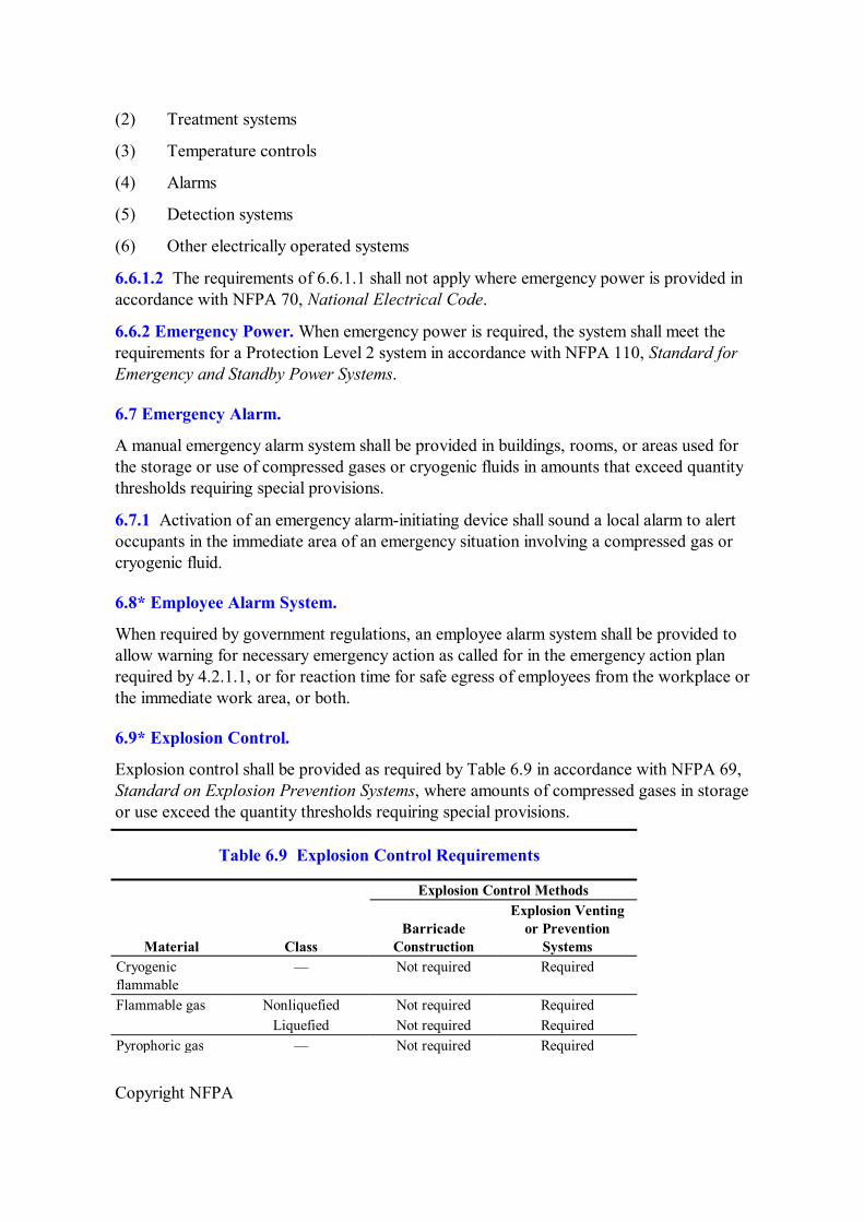
6.9* Explosion Control.
Explosion control shall be provided as required by Table 6.9 in accordance with NFPA 69, Standard on Explosion Prevention Systems, where amounts of compressed gases in storage or use exceed the quantity thresholds requiring special provisions.
Table 6.9 Explosion Control Requirements
Explosion Control Methods
Material Class Barricade
Construction
Explosion Venting or Prevention
Systems Cryogenic flammable
— Not required Required
Flammable gas Nonliquefied Not required Required Liquefied Not required Required
Pyrophoric gas — Not required Required

Copyright NFPA
Table 6.9 Explosion Control Requirements
Explosion Control Methods
Material Class Barricade
Construction
Explosion Venting or Prevention
Systems Unstable reactive gas
4 Required Not required
3 (detonable) Required Not required 3 (nondetonable) Not required Required
6.10* Fire Protection Systems.
Except as provided in 6.10.1, buildings or portions thereof required to comply with Protection Levels 1 through 5 shall be protected by an approved automatic fire sprinkler system complying with NFPA 13, Standard for the Installation of Sprinkler Systems.
6.10.1 Rooms or areas that are of noncombustible construction with wholly noncombustible contents shall not be required to be protected by an automatic fire sprinkler system.
6.10.2 Sprinkler System Design.
6.10.2.1 When sprinkler protection is provided, the area in which compressed gases or cryogenic fluids are stored or used shall be protected with a sprinkler system designed to be not less than that required by NFPA 13 for Ordinary Hazard Group 2 with a minimum design area of 278.7 m 2 (3000 ft 2 ).
6.10.2.2 When sprinkler protection is provided, the area in which the flammable or pyrophoric compressed gases or cryogenic fluids are stored or used shall be protected with a sprinkler system designed to be not less than that required by NFPA 13 for Extra Hazard Group 1 with a minimum design area of 232.25 m 2 (2500 ft 2 ).
6.11 Lighting.
Approved lighting by natural or artificial means shall be provided.
6.12 Hazard Identification Signs.
6.12.1 Location. Hazard identification signs shall be placed at all entrances to locations where compressed gases are produced, stored, used, or handled in accordance with NFPA 704, Standard System for the Identification of the Hazards of Materials for Emergency Response.
6.12.1.1 Ratings shall be assigned in accordance with NFPA 704.
6.12.1.2 The authority having jurisdiction shall be permitted to waive this requirement where consistent with safety.
6.12.2 Application. Signage shall be provided as specified in 6.12.2.1 and 6.12.2.2.

Copyright NFPA
6.12.2.1 Signs. Signs shall not be obscured or removed.
6.12.2.2 No Smoking. Signs prohibiting smoking or open flames within 7.6 m (25 ft) of area perimeters shall be provided in areas where toxic, highly toxic, corrosive, unstable reactive, flammable, oxidizing, or pyrophoric gases are produced, stored, or used.
6.13 Spill Control, Drainage, and Secondary Containment.
Spill control, drainage, and secondary containment shall not be required for compressed gases.
6.14 Shelving.
6.14.1 Shelves used for the storage of cylinders, containers, and tanks shall be of noncombustible construction and designed to support the weight of the materials stored.
6.14.2 In seismically active areas, shelves and containers shall be secured from overturning.
6.15 Vent Pipe Termination.
The termination point for piped vent systems serving cylinders, containers, tanks, and gas systems used for the purpose of operational or emergency venting shall be located to prevent impingement exposure on the system served and to minimize the effects of high temperature thermal radiation or the effects of contact with the gas from the escaping plume to the supply system, personnel, adjacent structures, and ignition sources.
6.16 Ventilation.
Indoor storage and use areas and storage buildings for compressed gases and cryogenic fluids shall be provided with mechanical exhaust ventilation or natural ventilation, where natural ventilation can be shown to be acceptable for the material as stored.
6.16.1 Mechanical Ventilation. Where mechanical ventilation is provided, the system shall be operational during the time the building or space is occupied.
6.16.2 Compressed Air. The requirements of Section 6.16 and 6.16.1 shall not apply to cylinders, containers, and tanks containing compressed air.
6.16.3 Mechanical Ventilation Rate. Mechanical ventilation shall be at a rate of not less than 0.3048 m 3 /min/m 2 (1 ft 3 /min/ft 2 ) of floor area over the area of storage or use.
6.16.4 Continuous Operation. Systems shall operate continuously unless an alternate design is approved by the code official.
6.16.5 Shutoff Controls. Where powered ventilation is provided, a manual shutoff switch shall be provided outside of the room in a position adjacent to the principal access door to the room or in an approved location.
6.16.6 Manual Shutoff Switch. The switch shall be the breakglass or equivalent type and shall be labeled as follows:
WARNING: VENTILATION SYSTEM EMERGENCY SHUTOFF

Copyright NFPA
6.16.7 Inlets to the Exhaust System.
6.16.7.1 The exhaust ventilation system design shall take into account the density of the potential gases released.
6.16.7.2 For gases that are heavier than air, exhaust shall be taken from a point within 12 in. (304.8 mm) of the floor.
6.16.7.3 For gases that are lighter than air, exhaust shall be taken from a point within 12 in. (304.8 mm) of the ceiling.
6.16.8 Floor Level Exhaust. The location of both the exhaust and inlet air openings shall be designed to provide air movement across all portions of the floor or room to prevent the accumulation of vapors.
6.16.9 Recirculation of Exhaust. Exhaust ventilation shall not be recirculated within the room or building if the cylinders, containers, or tanks stored are capable of releasing hazardous gases.
6.16.10 Ventilation Discharge. Ventilation systems shall discharge a minimum of 15 m (50 ft) from intakes of airhandling systems, airconditioning equipment, and air compressors.
6.16.11 Air Intakes. Storage and use of compressed gases shall be located not less than 15 m (50 ft) from air intakes. For materialspecific requirements, see Sections 7.4 through 7.10.
6.17 Gas Cabinets.
Where a gas cabinet is required, is used to provide separation of gas hazards, or is used to increase the threshold quantity for a gas requiring special provisions, the gas cabinet shall be in accordance with the requirements of 6.17.1 through 6.17.5.
6.17.1 Construction.
6.17.1.1 Materials of Construction. The gas cabinet shall be constructed of not less than 2.46 mm (0.097 in.) (12 gauge) steel.
6.17.1.2 Access to Controls. The gas cabinet shall be provided with selfclosing limited access ports or noncombustible windows to give access to equipment controls.
6.17.1.3 SelfClosing Doors. The gas cabinet shall be provided with selfclosing doors.
6.17.2 Ventilation Requirements.
6.17.2.1 The gas cabinet shall be provided with an exhaust ventilation system designed to operate at a negative pressure relative to the surrounding area.
6.17.2.2 Where toxic; highly toxic; pyrophoric; unstable, reactive Class 3 or Class 4; or corrosive gases are contained, the velocity at the face of access ports or windows, with the access port or window open, shall not be less than 61 m/min (200 ft/min) average, with not less than 46 m/min (150 ft/min) at any single point.
6.17.3 Fire Protection. Gas cabinets used to contain toxic, highly toxic, or pyrophoric gases shall be internally sprinklered.

Copyright NFPA
6.17.4 Quantity Limits. Gas cabinets shall contain not more than three containers, cylinders, or tanks.
6.17.5 Separation of Incompatibles. Incompatible gases, as defined by Table 7.1.6.2, shall be stored or used within separate gas cabinets.
6.18 Exhausted Enclosures.
6.18.1 Ventilation Requirements. Where an exhausted enclosure is required or used to increase the threshold quantity for a gas requiring special provisions, the exhausted enclosure shall be provided with an exhaust ventilation system designed to operate at a negative pressure in relationship to the surrounding area.
6.18.1.1 Control Velocity at Access Openings. Where toxic; highly toxic; pyrophoric; unstable, reactive Class 3 or Class 4; or corrosive gases are contained, the velocity at the face openings providing access shall be not less than 61 m/min (200 ft/min) average, with not less than 46 m/min (150 ft/min) at any single point.
6.18.1.2 Separation of Incompatible Gases within Enclosures. Cylinders, containers, and tanks within enclosures shall be separated in accordance with Table 7.1.6.2.
6.18.1.3 Fire Protection. Exhausted enclosures shall be internally sprinklered.
6.18.2 Separation. Incompatible gases, as defined by Table 7.1.6.2, shall be stored or used within separate exhausted enclosures.
Chapter 7 Compressed Gases
7.1 General.
The storage, use, and handling of compressed gases in containers, cylinders, and tanks shall be in accordance with the provisions of Chapters 1 through 7.
7.1.1* Listed and Approved Hydrogen Equipment.
7.1.1.1 Listed and approved hydrogen generating and consuming equipment shall be in accordance with the listing requirements and manufacturers' instructions.
7.1.1.2 Such equipment shall not be required to meet the requirements of Chapter 7.
7.1.2 Containers, Cylinders, and Tanks.
7.1.2.1 Design and Construction. Containers, cylinders, and tanks shall be designed, fabricated, tested, and marked (stamped) in accordance with regulations of DOT, Transport Canada (TC) Transportation of Dangerous Goods Regulations, or the ASME Boiler and Pressure Vessel Code, “Rules for the Construction of Unfired Pressure Vessels,” Section VIII.
7.1.2.2 Defective Containers, Cylinders, and Tanks.
7.1.2.2.1 Defective containers, cylinders, and tanks shall be returned to the supplier.

Copyright NFPA
7.1.2.2.2 Suppliers shall either repair the containers, cylinders, and tanks, remove them from service, or dispose of them in an approved manner.
7.1.2.3 Supports. Stationary cylinders, containers, and tanks shall be provided with engineered supports of noncombustible material on noncombustible foundations.
7.1.2.4 Containers, Cylinders, and Tanks Containing Residual Gas. Compressed gas containers, cylinders, and tanks containing residual product shall be treated as full except when being examined, serviced, or refilled by a gas manufacturer or distributor.
7.1.2.5 PressureRelief Devices.
7.1.2.5.1 When required by 7.1.2.5.2, pressurerelief devices shall be provided to protect containers and systems containing compressed gases from rupture in the event of overpressure from thermal exposure.
7.1.2.5.2 Pressurerelief devices to protect containers shall be designed and provided in accordance with CGA S1.1, Pressure Relief Device Standards – Part 1– Cylinders for Compressed Gases, for cylinders; CGA S1.2, Pressure Relief Device Standards – Part 2 – Cargo and Portable Tanks for Compressed Gases, for portable tanks; and CGA S1.3, Pressure Relief Device Standards – Part 3 – Stationary Storage Containers for Compressed Gases, for stationary tanks or applicable equivalent requirements in the country of use.
7.1.2.5.3 Pressurerelief devices shall be sized in accordance with the specifications to which the container was fabricated.
7.1.2.5.4 The pressurerelief device shall have the capacity to prevent the maximum design pressure of the container or system from being exceeded.
7.1.2.5.5 Pressurerelief devices shall be arranged to discharge upward and unobstructed to the open air in such a manner as to prevent any impingement of escaping gas upon the container, adjacent structures, or personnel. This requirement shall not apply to DOT specification containers having an internal volume of 2.0 ft 3 (0.057 m 3 ) or less.
7.1.2.5.6 Pressurerelief devices or vent piping shall be designed or located so that moisture cannot collect and freeze in a manner that would interfere with operation of the device.
7.1.3 Labeling Requirements.
7.1.3.1 Containers. Individual compressed gas containers, cylinders, and tanks shall be marked or labeled in accordance with DOT requirements or those of the applicable regulatory agency.
7.1.3.2 Label Maintenance. The labels applied by the gas manufacturer to identify the liquefied or nonliquefied compressed gas cylinder contents shall not be altered or removed by the user.
7.1.3.3 Stationary Compressed Gas Containers, Cylinders, and Tanks.
7.1.3.3.1 Stationary compressed gas containers, cylinders, and tanks shall be marked in accordance with NFPA 704, Standard System for the Identification of the Hazards of Materials for Emergency Response.

Copyright NFPA
7.1.3.3.2 Markings shall be visible from any direction of approach.
7.1.3.4 Piping Systems.
7.1.3.4.1 Except as provided in 7.1.3.4.2, piping systems shall be marked in accordance with ASME A13.1, Scheme for the Identification of Piping Systems, or other applicable approved standards as follows:
(1) Marking shall include the name of the gas and a directionofflow arrow.
(2) Piping that is used to convey more than one gas at various times shall be marked to provide clear identification and warning of the hazard.
(3) Markings for piping systems shall be provided at the following locations:
(a) At each critical process control valve
(b) At wall, floor, or ceiling penetrations
(c) At each change of direction
(d) At a minimum of every 6.1 m (20 ft) or fraction thereof throughout the piping run
7.1.3.4.2 Piping within gasmanufacturing plants, gasprocessing plants, refineries, and similar occupancies shall be marked in an approved manner.
7.1.4 Security.
7.1.4.1 General. Compressed gas containers, cylinders, tanks, and systems shall be secured against accidental dislodgement and against access by unauthorized personnel.
7.1.4.2 Security of Areas. Storage, use, and handling areas shall be secured against unauthorized entry.
7.1.4.3 Physical Protection.
7.1.4.3.1 Compressed gas containers, cylinders, tanks, and systems that could be exposed to physical damage shall be protected.
7.1.4.3.2 Guard posts or other means shall be provided to protect compressed gas containers, cylinders, tanks, and systems indoors and outdoors from vehicular damage.
7.1.4.4 Securing Compressed Gas Containers, Cylinders, and Tanks. Compressed gas containers, cylinders, and tanks in use or in storage shall be secured to prevent them from falling or being knocked over by corralling them and securing them to a cart, framework, or fixed object by use of a restraint, unless otherwise permitted by 7.1.4.4.1 and 7.1.4.4.2.
7.1.4.4.1 Compressed gas containers, cylinders, and tanks in the process of examination, servicing, and refilling shall not be required to be secured.
7.1.4.4.2 At cylinderfilling plants and distributors' warehouses, the nesting of cylinders shall be permitted as a means to secure cylinders.
7.1.5 Valve Protection.

Copyright NFPA
7.1.5.1 General. Compressed gas container, cylinder, and tank valves shall be protected from physical damage by means of protective caps, collars, or similar devices.
7.1.5.2 ValveProtective Caps. Where compressed gas containers, cylinders, and tanks are designed to accept valveprotective caps, the user shall keep such caps on the compressed gas containers, cylinders, and tanks at all times, except when empty, being processed, or connected for use.
7.1.5.3 Valve Outlet Caps or Plugs.
7.1.5.3.1 Gastight valve outlet caps or plugs shall be provided and in place for all full or partially full containers, cylinders, and tanks containing toxic, highly toxic, pyrophoric, or unstable reactive Class 3 or Class 4 gases that are in storage.
7.1.5.3.2 Valve outlet caps and plugs shall be designed and rated for the container service pressure.
7.1.6 Separation from Hazardous Conditions.
7.1.6.1 General.
7.1.6.1.1 Compressed gas containers, cylinders, tanks, and systems in storage or use shall be separated from materials and conditions that present exposure hazards to or from each other.
7.1.6.1.2 Compressed gas containers, cylinders, tanks, and systems in storage or use shall be separated in accordance with 7.1.6.
7.1.6.1.3 Paragraph 7.1.6.1.2 shall not apply to gases contained within closed piping systems, compressed gas containers, cylinders, tanks, and systems in storage or use when separated in accordance with 7.1.6.
7.1.6.2* Incompatible Materials. Gas containers, cylinders, and tanks shall be separated in accordance with Table 7.1.6.2.
Table 7.1.6.2 Separation of Gas Containers, Cylinders, and Tanks by Hazard Class
Gas Category Other Gas
Unstable Reactive Class 2, Class 3, or Class 4 Corrosive Oxidizing Flammable
Toxic or highly toxic NR 6.1 m (20 ft) 6.1 m (20 ft) 6.1 m (20 ft) 6.1 m (20 ft) Pyrophoric NR 6.1 m (20 ft) 6.1 m (20 ft) 6.1 m (20 ft) 6.1 m (20 ft) Flammable NR 6.1 m (20 ft) 6.1 m (20 ft) 6.1 m (20 ft) — Oxidizing NR 6.1 m (20 ft) 6.1 m (20 ft) — 6.1 m (20 ft) Corrosive NR 6.1 m (20 ft) — 6.1 m (20 ft) 6.1 m (20 ft) Unstable reactive Class 2, Class 3, or Class 4
NR — 6.1 m (20 ft) 6.1 m (20 ft) 6.1 m (20 ft)
Other Gas — NR NR NR NR NR: No separation required.
7.1.6.2.1 The 6.1 m (20 ft) distance shall be permitted to be reduced without limit when

Copyright NFPA
separated by a barrier of noncombustible materials at least 1.5 m (5 ft) high that has a fire resistance rating of at least 0.5 hour.
7.1.6.2.2 The 6.1 m (20 ft) distance shall be permitted to be reduced to 1.5 m (5 ft) where one of the gases is enclosed in a gas cabinet or without limit where both gases are enclosed in gas cabinets.
7.1.6.2.3 Cylinders without pressurerelief devices shall not be stored without separation from flammable and pyrophoric gases with pressurerelief devices.
7.1.6.2.4 Spatial separation shall not be required between cylinders deemed to be incompatible that are connected to manifolds for the purposes of filling and manufacturing procedures assuming the prescribed controls for the manufacture of gas mixtures are in place.
7.1.6.3 Clearance from Combustibles and Vegetation. Combustible waste, vegetation, and similar materials shall be kept a minimum of 3 m (10 ft) from compressed gas containers, cylinders, tanks, and systems.
7.1.6.3.1 A noncombustible partition without openings or penetrations and extending sides not less than 457 mm (18 in.) above and to the sides of the storage area shall be permitted in lieu of the minimum distance.
7.1.6.3.2 The noncombustible partition shall either be an independent structure or the exterior wall of the building adjacent to the storage area.
7.1.6.4 Ledges, Platforms, and Elevators. Compressed gas containers, cylinders, and tanks shall not be placed near elevators, unprotected platform ledges, or other areas where compressed gas containers, cylinders, or tanks could fall for distances exceeding onehalf the height of the container, cylinder, or tank.
7.1.6.5 Temperature Extremes. Compressed gas containers, cylinders, and tanks, whether full or partially full, shall not be exposed to temperatures exceeding 52°C (125°F) or subambient (low) temperatures unless designed for use under such exposure.
7.1.6.6 Falling Objects. Compressed gas containers, cylinders, and tanks shall not be placed in areas where they are capable of being damaged by falling objects.
7.1.6.7 Heating. Compressed gas containers, cylinders, and tanks, whether full or partially full, shall not be heated by devices that could raise the surface temperature of the container, cylinder, or tank to above 52°C (125°F).
7.1.6.7.1 Electrically Powered Heating Devices. Electrical heating devices shall be in accordance with NFPA 70, National Electrical Code.
7.1.6.7.2 FailSafe Design. Devices designed to maintain individual compressed gas containers, cylinders, or tanks at constant temperature shall be designed to be failsafe.
7.1.6.8 Sources of Ignition. Open flames and hightemperature devices shall not be used in a manner that creates a hazardous condition.
7.1.6.9 Exposure to Chemicals. Compressed gas containers, cylinders, and tanks shall not

Copyright NFPA
be exposed to corrosive chemicals or fumes that could damage containers, cylinders, tanks, or valveprotective caps.
7.1.6.10 Exposure to Electrical Circuits. Compressed gas containers, cylinders, and tanks shall not be placed where they could become a part of an electrical circuit.
7.1.7 Service and Repair. Service, repair, modification, or removal of valves, pressurerelief devices, or other compressed gas container, cylinder, or tank appurtenances shall be performed by trained personnel and with the permission of the container owner.
7.1.8 Unauthorized Use. Compressed gas containers, cylinders, and tanks shall not be used for any purpose other than to serve as a vessel for containing the product for which it was designed.
7.1.9 Containers, Cylinders, and Tanks Exposed to Fire. Compressed gas containers, cylinders, and tanks exposed to fire shall not be used or shipped while full or partially full until they are requalified in accordance with the pressure vessel code under which they were manufactured.
7.1.10 Leaks, Damage, or Corrosion.
7.1.10.1 Removal From Service. Leaking, damaged, or corroded compressed gas containers, cylinders, and tanks shall be removed from service.
7.1.10.2 Replacement and Repair. Leaking, damaged, or corroded compressed gas systems shall be replaced or repaired.
7.1.10.3* Handling of Containers, Cylinders, and Tanks Removed from Service. Compressed gas containers, cylinders, and tanks that have been removed from service shall be handled in an approved manner.
7.1.10.4 Leaking Systems. Compressed gas systems that are determined to be leaking, damaged, or corroded shall be repaired to a serviceable condition or shall be removed from service.
7.1.11 Surfaces.
7.1.11.1 To prevent bottom corrosion, containers, cylinders, and tanks shall be protected from direct contact with soil or surfaces where water might accumulate.
7.1.11.2 Surfaces shall be graded to prevent accumulation of water.
7.1.12 Storage Area Temperature.
7.1.12.1 Compressed Gas Containers. Storage area temperatures shall not exceed 52°C (125°F).
7.2 Storage.
7.2.1 General.
7.2.1.1 Applicability. The storage of compressed gas containers, cylinders, and tanks shall be in accordance with Section 7.2.

Copyright NFPA
7.2.1.2 Upright Storage Flammable Gas in Solution and Liquefied Flammable Gas. Cylinders, containers, and tanks containing liquefied flammable gases and flammable gases in solution shall be positioned in the upright position.
7.2.1.2.1 Containers and Cylinders of 5 L (1.3 Gal) or Less. Containers with a capacity of 5 L (1.3 gal) or less shall be permitted to be stored in a horizontal position.
7.2.1.2.2 Containers, Cylinders, and Tanks Designed for Horizontal Use. Containers, cylinders, and tanks designed for use in a horizontal position shall be permitted to be stored in a horizontal position.
7.2.1.2.3 Palletized Containers, Cylinders, and Tanks. Containers, cylinders, and tanks, with the exception of those containing flammable liquefied compressed gases, that are palletized for transportation purposes shall be permitted to be stored in a horizontal position.
7.2.1.3 Classification of Weather Protection as an Indoor Versus Outdoor Area. For other than explosive materials and hazardous materials presenting a detonation hazard, a weather protection structure shall be permitted to be used for sheltering outdoor storage or use areas, without requiring such areas to be classified as indoor storage.
7.2.2 MaterialSpecific Regulations.
7.2.2.1 Indoor Storage. Indoor storage of compressed gases shall be in accordance with the materialspecific provisions of Sections 7.4 through 7.10.
7.2.2.2 Exterior Storage.
7.2.2.2.1 General. Exterior storage of compressed gases shall be in accordance with the materialspecific provisions of Sections 7.4 through 7.10.
7.2.2.2.2 Separation. Distances from property lines, buildings, and exposures shall be in accordance with the materialspecific provisions of Sections 7.4 through 7.10.
7.3 Use and Handling.
7.3.1 General.
7.3.1.1 Applicability. The use and handling of compressed gas containers, cylinders, tanks, and systems shall be in accordance with 7.3.1.
7.3.1.2 Compressed Gas Systems. Compressed gas systems shall be designed for the intended use and shall be designed by persons competent in such design.
7.3.1.2.1 Installation of bulk cryogenic fluid systems shall be supervised by personnel knowledgeable in the application of the standards for their construction and use.
7.3.1.2.2 Installation of bulk compressed gas systems shall be supervised by personnel knowledgeable in the application of the standards for their construction and use.
7.3.1.3 Controls.
7.3.1.3.1 Compressed gas system controls shall be designed to prevent materials from entering or leaving the process at an unintended time, rate, or path.

Copyright NFPA
7.3.1.3.2 Automatic controls shall be designed to be failsafe.
7.3.1.4 Piping Systems. Piping, tubing, fittings, and related components shall be designed, fabricated, and tested in accordance with the requirements of ASME B31.3, Process Piping, or other approved standards.
7.3.1.4.1 Integrity. Piping, tubing, pressure regulators, valves, and other apparatus shall be kept gastight to prevent leakage.
7.3.1.4.2 Backflow Prevention. Backflow prevention or check valves shall be provided when the backflow of hazardous materials could create a hazardous condition or cause the unauthorized discharge of hazardous materials.
7.3.1.5 Valves.
7.3.1.5.1 Valves utilized on compressed gas systems shall be designed for the gas or gases and pressure intended and shall be accessible.
7.3.1.5.2 Valve handles or operators for required shutoff valves shall not be removed or otherwise altered to prevent access.
7.3.1.6 Vent Pipe Termination.
7.3.1.6.1 Venting of gases shall be directed to an approved location.
7.3.1.6.2 The termination point for piped vent systems serving cylinders, containers, tanks, and gas systems used for the purpose of operational or emergency venting shall be in accordance with Section 6.16.
7.3.1.7 Upright Use.
7.3.1.7.1 Compressed gas containers, cylinders, and tanks containing flammable liquefied gas, except those designed for use in a horizontal position and those compressed gas containers, cylinders, and tanks containing nonliquefied gases, shall be used in a “valve end up” upright position.
7.3.1.7.2 An upright position shall include a position in which the container, cylinder, or tank axis is inclined as much as 45 degrees from the vertical and in which the relief device is always in direct communication with the gas phase.
7.3.1.8 Inverted Use. Cylinders, containers, and tanks containing nonflammable liquefied gases shall be permitted to be used in the inverted position when the liquid phase is used.
7.3.1.8.1 Flammable liquefied gases at processing plants shall be permitted to use this inverted position method while transfilling.
7.3.1.8.2 The container, cylinder, or tank shall be secured, and the dispensing apparatus shall be designed for use with liquefied gas.
7.3.1.9 Containers and Cylinders of 5 L (1.3 Gal) or Less. Containers or cylinders with a water volume of 5 L (1.3 gal) or less shall be permitted to be used in a horizontal position.
7.3.1.10 Transfer.

Copyright NFPA
7.3.1.10.1 Transfer of gases between containers, cylinders, and tanks shall be performed by qualified personnel using equipment and operating procedures in accordance with CGA P1, Safe Handling of Compressed Gases in Containers.
7.3.1.10.2 The requirements of 7.3.1.10.1 shall not apply to fueling of vehicles with compressed natural gas (CNG).
7.3.1.11 Use of Compressed Gases for Inflation. Inflatable equipment, devices, or balloons shall only be pressurized or filled with compressed air or inert gases.
7.3.1.12 Emergency Shutoff Valves.
7.3.1.12.1 Accessible manual valves or automatic remotely activated failsafe emergency shutoff valves shall be provided and clearly marked.
7.3.1.12.2 Emergency shutoffs shall be located at the point of use and at the tank, cylinder, or bulk source.
7.3.1.13 Excess Flow Control. Excess flow control shall be provided, where required by 7.3.1.13.1, for compressed gases with a hazard rating in accordance with NFPA 704, Standard System for the Identification of the Hazards of Materials for Emergency Response, as follows:
(1) Health hazard Class 3 or Class 4
(2) Flammability Class 4
(3) Reactivity Class 3 or Class 4
7.3.1.13.1 Excess Flow Control Above 103 kPa (15 psig). Excess flow control shall be provided for pressurized gas piping systems that are pressurized above 103 kPa (gauge pressure of 15 psi) where the source of the gas exceeds the quantity threshold in Table 6.3.1.
7.3.1.13.2 Location. The location of excess flow control shall be as specified in 7.3.1.13.2.1 and 7.3.1.13.2.2.
7.3.1.13.2.1 Where piping originates from a source located in a room or area, the excess flow control shall be located within the room or area.
7.3.1.13.2.2 Where piping originates from a bulk source, the excess flow control shall be as close to the bulk source as possible.
7.3.1.13.3 Location Requirement Exemptions. The requirements of 7.3.1.13 shall not apply to the following:
(1) Piping for inlet connections designed to prevent backflow
(2) Piping for pressurerelief devices
(3) Systems containing 12.7 m 3 (450 scf) or less of flammable gas
7.3.2 MaterialSpecific Regulations.
7.3.2.1 Indoor Use. Indoor use of compressed gases shall be in accordance with the

Copyright NFPA
requirements of Sections 7.4 through 7.10.
7.3.2.2 Exterior Use.
7.3.2.2.1 General. Exterior use of compressed gases shall be in accordance with the requirements of Sections 7.4 through 7.10.
7.3.2.2.2 Separation. Distances from property lines, buildings, and exposure hazards shall be in accordance with the materialspecific provisions of Sections 7.4 through 7.10.
7.3.3 Handling.
7.3.3.1 Applicability. The handling of compressed gas containers, cylinders, and tanks shall be in accordance with 7.3.3.
7.3.3.2 Carts and Trucks.
7.3.3.2.1 Containers, cylinders, and tanks shall be moved using an approved method.
7.3.3.2.2 Where containers, cylinders, or tanks are moved by hand cart, hand truck, or other mobile device, such carts, trucks, or devices shall be designed for the secure movement of containers, cylinders, or tanks.
7.3.3.3 Lifting Devices. Ropes, chains, or slings shall not be used to suspend compressed gas containers, cylinders, and tanks unless provisions at time of manufacture have been made on the container, cylinder, or tank for appropriate lifting attachments, such as lugs.
7.4 Medical Gas Systems.
Medical gas systems for health care shall be in accordance with NFPA 99, Standard for Health Care Facilities.
7.5 Corrosive Gases.
7.5.1 General. The storage or use of corrosive compressed gases exceeding the quantity thresholds for gases requiring special provisions as specified in Table 6.3.1 shall be in accordance with Chapters 1 through 6 and Sections 7.1 through 7.3 and 7.5.
7.5.2 Distance to Exposures. The outdoor storage or use of corrosive compressed gas shall not be within 6.1 m (20 ft) of buildings not associated with the manufacture or distribution of corrosive gases, lot lines, streets, alleys, public ways, or means of egress.
7.5.2.1 A 2hour fire barrier wall without openings or penetrations, and extending not less than 762 mm (30 in.) above and to the sides of the storage or use area, shall be permitted in lieu of the 6.1 m (20 ft) distance.
7.5.2.1.1 The fire barrier wall shall be either an independent structure or the exterior wall of the building adjacent to the storage or use area.
7.5.2.1.2 The 2hour fire barrier shall be located at least 1.5 m (5 ft) from any exposure.
7.5.2.1.3 The 2hour fire barrier shall not have more than two sides at approximately 1.57 rad (90 degree) directions, or not more than three sides with connecting angles of
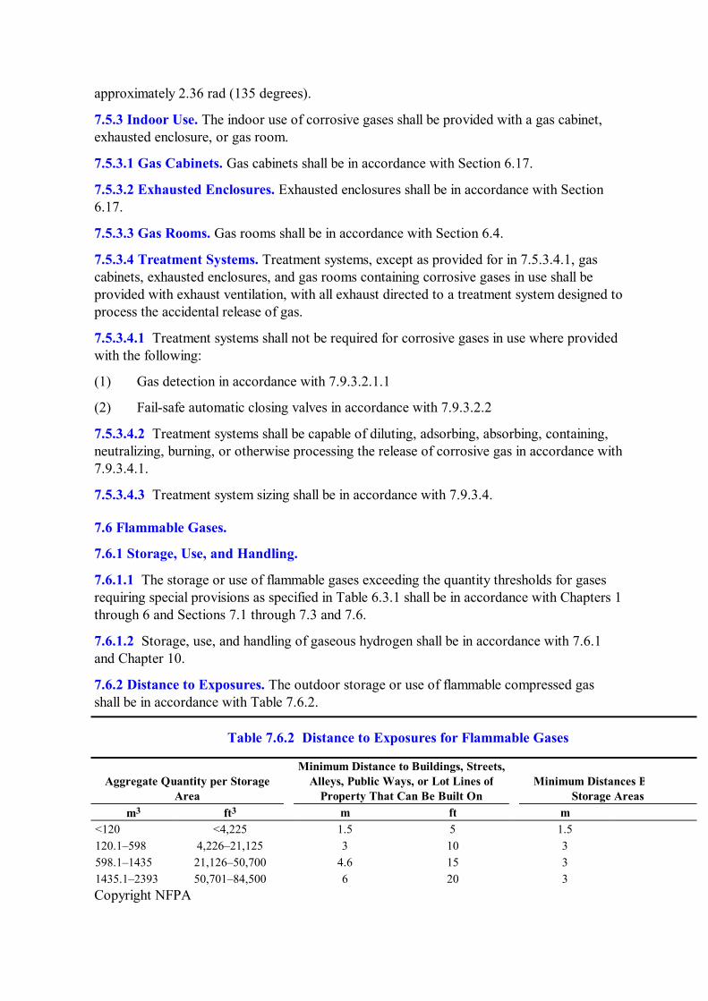
Copyright NFPA
approximately 2.36 rad (135 degrees).
7.5.3 Indoor Use. The indoor use of corrosive gases shall be provided with a gas cabinet, exhausted enclosure, or gas room.
7.5.3.1 Gas Cabinets. Gas cabinets shall be in accordance with Section 6.17.
7.5.3.2 Exhausted Enclosures. Exhausted enclosures shall be in accordance with Section 6.17.
7.5.3.3 Gas Rooms. Gas rooms shall be in accordance with Section 6.4.
7.5.3.4 Treatment Systems. Treatment systems, except as provided for in 7.5.3.4.1, gas cabinets, exhausted enclosures, and gas rooms containing corrosive gases in use shall be provided with exhaust ventilation, with all exhaust directed to a treatment system designed to process the accidental release of gas.
7.5.3.4.1 Treatment systems shall not be required for corrosive gases in use where provided with the following:
(1) Gas detection in accordance with 7.9.3.2.1.1
(2) Failsafe automatic closing valves in accordance with 7.9.3.2.2
7.5.3.4.2 Treatment systems shall be capable of diluting, adsorbing, absorbing, containing, neutralizing, burning, or otherwise processing the release of corrosive gas in accordance with 7.9.3.4.1.
7.5.3.4.3 Treatment system sizing shall be in accordance with 7.9.3.4.
7.6 Flammable Gases.
7.6.1 Storage, Use, and Handling.
7.6.1.1 The storage or use of flammable gases exceeding the quantity thresholds for gases requiring special provisions as specified in Table 6.3.1 shall be in accordance with Chapters 1 through 6 and Sections 7.1 through 7.3 and 7.6.
7.6.1.2 Storage, use, and handling of gaseous hydrogen shall be in accordance with 7.6.1 and Chapter 10.
7.6.2 Distance to Exposures. The outdoor storage or use of flammable compressed gas shall be in accordance with Table 7.6.2.
Table 7.6.2 Distance to Exposures for Flammable Gases
Aggregate Quantity per Storage Area
Minimum Distance to Buildings, Streets, Alleys, Public Ways, or Lot Lines of Property That Can Be Built On
Minimum Distances Between Storage Areas
m 3 ft 3 m ft m <120 <4,225 1.5 5 1.5 120.1–598 4,226–21,125 3 10 3 598.1–1435 21,126–50,700 4.6 15 3 1435.1–2393 50,701–84,500 6 20 3

Copyright NFPA
Table 7.6.2 Distance to Exposures for Flammable Gases
Aggregate Quantity per Storage Area
Minimum Distance to Buildings, Streets, Alleys, Public Ways, or Lot Lines of Property That Can Be Built On
Minimum Distances Between Storage Areas
m 3 ft 3 m ft m 2393.1 84,501 7.5 25 6
7.6.2.1 The minimum required distances shall be reduced to 1.5 m (5 ft) where protective structures having a minimum fire resistance rating of 2 hours interrupt the line of sight between the container and the exposure.
7.6.2.2 The protective structure shall be at least 1.5 m (5 ft) from the storage or use area perimeter.
7.6.2.3 The configuration of the protective structure shall be designed to allow natural ventilation to prevent the accumulation of hazardous gas concentrations.
7.6.2.4 Storage and use of flammable compressed gases shall not be located within 15.2 m (50 ft) of air intakes.
7.6.3 Ignition Source Control. Ignition sources in areas containing flammable gases shall be in accordance with 7.6.3.
7.6.3.1 StaticProducing Equipment. Staticproducing equipment located in flammable gas areas shall be grounded.
7.6.3.2 No Smoking or Open Flame. Signs shall be posted in areas containing flammable gases communicating that smoking or the use of open flame, or both, is prohibited within 7.6 m (25 ft) of the storage or use area perimeter.
7.6.4 Electrical. Areas in which the storage or use of compressed gases exceeds the quantity thresholds for gases requiring special provisions shall be in accordance with NFPA 70, National Electrical Code.
7.7 Oxidizing Gases.
7.7.1 General. The storage or use of oxidizing compressed gases exceeding the quantity thresholds for gases requiring special provisions as specified in Table 6.3.1 shall be in accordance with Chapters 1 through 6 and Sections 7.1 through 7.3 and 7.7.
7.7.2 Distance to Exposures. The outdoor storage or use of oxidizing compressed gas shall be in accordance with Table 7.7.2.
Table 7.7.2 Distance to Exposures for Oxidizing Gases
Quantity of Gas Stored (at NTP)
Distance to a Building Not Associated with the Manufacture or Distribution of
Oxidizing Gases or to a Public Way or Property Line
Minimum Distance Between Storage

Copyright NFPA
be in accordance with Table 7.7.2.
Table 7.7.2 Distance to Exposures for Oxidizing Gases
Quantity of Gas Stored (at NTP)
Distance to a Building Not Associated with the Manufacture or Distribution of
Oxidizing Gases or to a Public Way or Property Line
Minimum Distance Between Storage
m 3 ft 3 m ft m 0–1416 0–50,000 1.5 5 1.5 1417–2832 50,001–100,000 3.0 10 3.0
2833 100,001 4.6 15 4.6
7.7.2.1 The distances shall not apply where protective structures having a minimum fire resistance of 2 hours interrupt the line of sight between the container and the exposure.
7.7.2.2 The protective structure shall be at least 1.5 m (5 ft) from the storage or use area perimeter.
7.7.2.3 The configuration of the protective structure shall allow natural ventilation to prevent the accumulation of hazardous gas concentrations.
7.8 Pyrophoric Gases.
7.8.1 General. Pyrophoric compressed gases exceeding the quantity thresholds for gases requiring special provisions as specified in Table 6.3.1 shall be stored and used in accordance with Chapters 1 through 6 and Sections 7.1 through 7.3 and 7.8.
7.8.2 Silane and Silane Mixtures. Silane and silane mixtures shall be stored, used, and handled in accordance with the provisions of CGA P32, Safe Storage and Handling of Silane and Silane Mixtures.
7.8.3 Distance to Exposures. The outdoor storage or use of pyrophoric compressed gas shall be in accordance with Table 7.8.3.
Table 7.8.3 Distance to Exposures for Pyrophoric Gases
Minimum Distance to Buildings on the Same Property
Maximum Amount per Storage Area
Minimum Distance Between Storage Areas
Minimum Distance to Property Lines
Minimum Distance to Public Ways
Nonrated or Openings Within 25 ft (7.6 m)
ft 3 m 3 ft m ft m ft m ft m 250 7.1 5 1.5 25 7.6 5 1.5 5 1.5 2500 71.0 10 3.0 50 15.2 10 3.0 10 3.0 7500 212.4 20 6.0 100 30.5 20 6.0 20 6.0
7.8.3.1 The distances shall be allowed to be reduced to 1.5 m (5 ft) when protective

Copyright NFPA
structures having a minimum fire resistance of 2 hours interrupt the line of sight between the container and the exposure.
7.8.3.2 The protective structure shall be at least 1.5 m (5 ft) from the storage or use area perimeter.
7.8.3.3 The configuration of the protective structure shall allow natural ventilation to prevent the accumulation of hazardous gas concentrations.
7.9 Toxic and Highly Toxic Gases.
7.9.1 General. The storage or use of toxic and highly toxic gases exceeding the quantity thresholds for gases requiring special provisions as specified in Table 6.3.1 shall be in accordance with Chapters 1 through 6 and Sections 7.1 through 7.3 and 7.9.
7.9.2 Ventilation and Arrangement.
7.9.2.1 Indoors. The indoor storage or use of highly toxic gases or toxic gases shall be provided with a gas cabinet, exhausted enclosure, or gas room.
7.9.2.1.1 Gas cabinets shall be in accordance with Section 6.17.
7.9.2.1.2 Exhausted enclosures shall be in accordance with Section 6.18.
7.9.2.1.3 Gas rooms shall be in accordance with Section 6.4.
7.9.2.2 Distance to Exposures. The outdoor storage or use of toxic and highly toxic compressed gases shall not be within 23 m (75 ft) of lot lines, streets, alleys, public ways or means of egress, or buildings not associated with such storage or use.
7.9.2.2.1 A 2hour fire barrier wall without openings or penetrations, and extending not less than 762 mm (30 in.) above and to the sides of the storage or use area, that interrupts the line of sight between the storage or use and the exposure, shall be permitted in lieu of the 23 m (75 ft) distance.
7.9.2.2.1.1 The fire barrier wall shall be either an independent structure or the exterior wall of the building adjacent to the storage or use area.
7.9.2.2.1.2 The 2hour fire barrier shall be located at least 1.5 m (5 ft) from any exposure.
7.9.2.2.1.3 The 2hour fire barrier shall not have more than two sides at approximately 1.5 rad (90 degree) directions, or more than three sides with connecting angles of approximately 2.36 rad (135 degrees).
7.9.2.2.2 Where the storage or use area is located closer than 23 m (75 ft) to a building not associated with the manufacture or distribution of toxic or highly toxic compressed gases, openings in the building other than for piping shall not be permitted above the height of the top of the 2hour fire barrier wall or within 15 m (50 ft) horizontally from the storage area, regardless of whether the openings are shielded by a fire barrier.
7.9.2.3 Air Intakes. Storage and use of toxic and highly toxic compressed gases shall not be located within 23 m (75 ft) of air intakes.
7.9.3 Treatment Systems. Except as provided in 7.9.3.1 and 7.9.3.2, gas cabinets,

Copyright NFPA
exhausted enclosures, and gas rooms containing toxic or highly toxic gases shall be provided with exhaust ventilation, with all exhaust directed to a treatment system designed to process accidental release of gas.
7.9.3.1 Storage of Toxic or Highly Toxic Gases. Treatment systems shall not be required for toxic or highly toxic gases in storage where containers, cylinders, and tanks are provided with the controls specified in 7.9.3.1.1 through 7.9.3.1.3.
7.9.3.1.1 Valve Outlets Protected. Valve outlets shall be equipped with outlet plugs or caps, or both, rated for the container service pressure.
7.9.3.1.2 Handwheels Secured. Where provided, handwheeloperated valves shall be secured to prevent movement.
7.9.3.1.3 Containment Devices Provided. Approved cylinder containment vessels or cylinder containment systems shall be provided at an approved location.
7.9.3.2 Use of Toxic Gases. Treatment systems shall not be required for toxic gases in use where containers, cylinders, and tanks are provided with the controls specified in 7.9.3.2.1 and 7.9.3.2.2.
7.9.3.2.1 Gas Detection.
7.9.3.2.1.1 A gas detection system with a sensing interval not exceeding 5 minutes shall be provided.
7.9.3.2.1.2 The gas detection system shall monitor the exhaust system at the point of discharge from the gas cabinet, exhausted enclosure, or gas room.
7.9.3.2.2 FailSafe Automatic Closing Valve. An approved automaticclosing failsafe valve shall be located immediately adjacent to and downstream of active container, cylinder, or tank valves.
7.9.3.2.2.1 The failsafe valve shall close when gas is detected at the permissible exposure limit, shortterm exposure limit (STEL), or ceiling limit by the gas detection system.
7.9.3.2.2.2 For attended operations, a manual closing valve shall be permitted when in accordance 7.9.3.4.3.
7.9.3.2.2.3 For gases used at unattended operations for the protection of public health, such as chlorine at water or wastewater treatment sites, the automatic valve shall close if the concentration of gas detected by a gas detection system reaches onehalf of the IDLH.
7.9.3.2.2.4 The gas detection system shall also alert persons onsite and a responsible person offsite when the gas concentration in the storage/use area reaches the OSHA PEL, OSHA ceiling limit, or STEL for the gas employed.
7.9.3.3 Treatment System Design and Performance. Treatment systems shall be capable of diluting, adsorbing, absorbing, containing, neutralizing, burning, or otherwise processing stored or used toxic or highly toxic gas, or both.
7.9.3.3.1 Where a total containment system is used, the system shall be designed to handle the maximum anticipated pressure of release to the system when it reaches equilibrium.

Copyright NFPA
7.9.3.3.2 Treatment systems shall be capable of reducing the allowable discharge concentrations to onehalf the IDLH threshold at the point of discharge.
7.9.3.4 Treatment System Sizing.
7.9.3.4.1 WorstCase Release of Gas. Treatment systems shall be sized to process the maximum worstcase release of gas based on the maximum flow rate of release from the largest vessel utilized in accordance with 7.9.3.4.2.
7.9.3.4.2 Largest Compressed Gas Vessel. The entire contents of the single largest compressed gas vessel shall be considered.
7.9.3.4.3 Attended Operations — Alternative Method of System Sizing.
7.9.3.4.3.1 Where source containers, cylinders, and tanks are used in attended process operations, with an operator present at the enclosure where the activity occurs, the volume of the release shall be limited to the estimated amount released from the process piping system within a period not to exceed 5 minutes.
7.9.3.4.3.2 Such process piping systems shall comply with the requirements of 7.9.3.4.3.2(A) through 7.9.3.4.3.2(E).
(A) Local Exhaust. All gas transfer operations shall be conducted within a zone of local exhaust that is connected to a treatment system.
(B) Gas Detection. Gas detection shall be used to provide a warning to alert the operators to emission of gas into the zone of local exhaust, and the following requirements also shall apply:
(1) The system shall be capable of detecting gas at the permissible exposure limit or ceiling limit for the gas being processed.
(2) Activation of the gas detection system shall provide a local alarm.
(C) Process Shutdown. Operations involving the gas detected shall be shut down and leaks repaired.
(D) Piping System Construction. Piping systems used to convey gases shall be of allwelded construction throughout, with the exception of fittings used to connect containers, cylinders, or tanks, or any combination thereof, to the process system.
(E) Piping System Accessibility. Piping systems shall be designed to provide for readily accessible manual shutdown controls.
7.9.3.5 Rate of Release. The time release shall be in accordance with Table 7.9.3.5 for the type of container indicated.
Table 7.9.3.5 Rates of Release
Container Type Nonliquefied Gases (min) Liquefied Gases (min) Cylinders without restrictive flow orifices
5 30

Copyright NFPA
Table 7.9.3.5 Rates of Release
Container Type Nonliquefied Gases (min) Liquefied Gases (min) Portable tanks without restrictive flow orifices
40 240
All others Based on peak flow from maximum valve orifice
Based on peak flow from maximum valve orifice
7.9.3.6* Maximum Flow Rate of Release.
7.9.3.6.1 For portable containers, cylinders, and tanks, the maximum flow rate of release shall be calculated based on assuming the total release from the cylinder or tank within the time specified.
7.9.3.6.2 When portable containers, cylinders, or tanks are equipped with reduced flow orifices, the worstcase rate of release shall be determined by the maximum achievable flow from the valve determined based on the following formula:
where:
CFM = standard cubic feet per minute of gas of concern under flow conditions A = area of orifice in square inches (See Table A.7.9.3.6 for areas of typical restricted flow orifices.) P = supply pressure of gas at NTP in pounds per square inch absolute MW = molecular weight
7.9.3.6.3 For mixtures, the average of molecular weights shall be used.
7.9.4 Leaking Containers, Cylinders, and Tanks. When containers, cylinders, or tanks are used outdoors, in excess of the quantities specified in the column for unsprinklered areas (unprotected by gas cabinets or exhausted enclosures) in Table 6.3.1, a gas cabinet, exhausted enclosure, or containment vessel or system shall be provided to control leaks from leaking containers, cylinders, and tanks in accordance with 7.9.4.1 through 7.9.4.2.3.
7.9.4.1 Gas Cabinets or Exhausted Enclosures. Where gas cabinets or exhausted enclosures are provided to handle leaks from containers, cylinders, or tanks, exhaust ventilation shall be provided that is directed to a treatment system in accordance with the provisions of 7.9.3.
7.9.4.2 Containment Vessels or Systems. Where containment vessels or containment systems are provided, they shall comply with the requirements of 7.9.4.2.1 through 7.9.4.2.3.
7.9.4.2.1 Performance. Containment vessels or containment systems shall be capable of fully containing or terminating a release.
7.9.4.2.2 Personnel. Trained personnel capable of operating the containment vessel or

Copyright NFPA
containment system shall be available at an approved location.
7.9.4.2.3 Location. Containment vessels or systems shall be capable of being transported to the leaking cylinder, container, or tank.
7.9.5 Emergency Power.
7.9.5.1 General. Emergency power shall comply with the requirements of 7.9.5 in accordance with NFPA 70, National Electrical Code.
7.9.5.2 Alternative to Emergency Power. Emergency power shall not be required where failsafe engineering is provided for mechanical exhaust ventilation, treatment systems, and temperature control, and standby power is provided to alternative systems that utilize electrical energy.
7.9.5.3 Where Required. Emergency power shall be provided for the following systems:
(1) Exhaust ventilation
(2) Treatment system
(3) Gas detection system
(4) Temperature control system
(5) Required alarm systems
7.9.5.4 Level. Emergency power systems shall comply with the requirements for a Level 2 system in accordance with NFPA 110, Standard for Emergency and Standby Power Systems.
7.9.6 Gas Detection. Except as provided in 7.9.6.1, a continuous gas detection system in accordance with the requirements of 7.9.6.2 through 7.9.6.6 shall be provided for the indoor storage or use of toxic or highly toxic compressed gases.
7.9.6.1 Where Gas Detection Is Not Required. A gas detection system shall not be required for toxic gases where the physiological warning properties for the gas are at a level below the accepted permissible exposure limit or ceiling limit for the gas.
7.9.6.2 Local Alarm. The gas detection system shall initiate a local alarm that is both audible and visible.
7.9.6.3 Alarm Monitored. The gas detection system shall transmit a signal to a constantly attended control station for quantities exceeding one toxic or highly toxic compressed gas cylinder.
7.9.6.4 Automatic Shutdown.
7.9.6.4.1 Activation of the gas detection system shall automatically shut off the flow of gas related to the system being monitored.
7.9.6.4.2 An automatic shutdown shall not be required for reactors utilized for the production of toxic or highly toxic gases when such reactors are operated at pressures less than 103.4 kPa (gauge pressure of 15 psi), constantly attended, and provided with readily

Copyright NFPA
accessible emergency shutoff valves.
7.9.6.5 Detection Points. Detection shall be provided at the locations specified in 7.9.6.5.1 through 7.9.6.5.4.
7.9.6.5.1 Treatment System Discharge. Detection shall be provided at the discharge from the treatment system.
7.9.6.5.2 Point of Use. Detection shall be provided in the room or area in which the gas is used.
7.9.6.5.3 Source. Detection shall be provided at the source container, cylinder, or tank used for delivery of the gas to the point of use.
7.9.6.5.4 Storage. Detection shall be provided in the room or area in which the gas is stored.
7.9.6.6 Level of Detection. The gas detection system shall detect the presence of gas at or below the permissible exposure limit or ceiling limit of the gas for those points identified in 7.9.6.5.2 and 7.9.6.5.3, and at not less than onehalf the IDLH level for points identified in 7.9.6.5.1.
7.9.7 Automatic Smoke Detection System. An automatic smoke detection system shall be provided for the indoor storage or use of highly toxic compressed gases in accordance with NFPA 72, National Fire Alarm Code.
7.10 Unstable Reactive Gases (Nondetonable).
The storage or use of unstable reactive (nondetonable) gases exceeding the quantity thresholds for gases requiring special provisions as specified in Table 6.3.1 shall be in accordance with Chapters 1 through 6 and Sections 7.1 through 7.3 and 7.10.
7.10.1 Distances to Exposures for Class 2.
7.10.1.1 The outdoor storage or use of unstable reactive Class 2 compressed gas shall not be within 23 m (75 ft) of buildings, lot lines, streets, alleys, or public ways or means of egress.
7.10.1.2 A 2hour fire barrier wall without openings or penetrations, and extending not less than 762 mm (30 in.) above and to the sides of the storage or use area, shall be permitted in lieu of the 23 m (75 ft) distance required by 7.10.1.1.
7.10.1.2.1 The fire barrier wall shall be either an independent structure or the exterior wall of the building.
7.10.1.2.2 The 2hour fire barrier shall be located at least 1.5 m (5 ft) from any exposure.
7.10.1.2.3 The 2hour fire barrier shall not have more than two sides at approximately 1.57 rad (90 degree) directions, or not more than three sides with connecting angles of approximately 2.36 rad (135 degrees).
7.10.2 Distances to Exposures for Class 3.
7.10.2.1 The outdoor storage or use of unstable reactive Class 3 (nondetonable) compressed gas shall not be within 23 m (75 ft) of buildings, lot lines, streets, alleys, or public ways or

Copyright NFPA
means of egress.
7.10.2.2 A 2hour fire barrier wall without openings or penetrations, and extending not less than 762 mm (30 in.) above and to the sides of the storage or use area, that interrupts the line of sight between the storage or use and the exposure shall be permitted in lieu of the 23 m (75 ft) distance specified in 7.10.2.1.
7.10.2.2.1 The fire barrier wall shall be either an independent structure or the exterior wall of the building adjacent to the storage or use area.
7.10.2.2.2 The 2hour fire barrier shall be located at least 1.5 m (5 ft) from any exposure.
7.10.2.2.3 The 2hour fire barrier shall not have more than two sides at approximately 1.57 rad (90 degree) directions, or more than three sides with connecting angles of approximately 2.36 rad (135 degrees).
7.10.2.2.4 The fire barrier shall be either an independent structure or the exterior wall of the building adjacent to the storage or use area.
7.10.3 Storage Configuration. Unstable reactive Class 3 compressed gases stored in cylinders, containers, or tanks shall be arranged to limit individual groups of cylinders, containers, or tanks to areas not exceeding 9.3 m 2 (100 ft 2 ). Multiple areas shall be separated by aisles. Aisle widths shall not be less than the height of the cylinders, containers, or tanks or 1.2 m (4 ft), whichever is greater.
7.10.4 Basements. Unstable reactive compressed gases shall not be stored in basements.
7.10.5 Unstable Reactive Gases (Detonable).
7.10.5.1 Storage or Use. The storage or use of unstable reactive (detonable) gases exceeding the quantity thresholds for gases requiring special provisions as specified in Table 6.3.1 shall be in accordance with Chapters 1 through 6, Sections 7.1 through 7.3, and 7.10.5.
7.10.5.2 Location. The location of storage areas shall be determined based on the requirements of the building code for explosive materials.
Chapter 8 Cryogenic Fluids
8.1 General.
8.1.1 Storage, use, and handling of cryogenic fluids shall be in accordance with Chapters 1 through 6 and Chapter 8.
8.2* Containers — Design, Construction, and Maintenance.
Containers employed for the storage or use of cryogenic fluids shall be designed, fabricated, tested, marked (stamped), and maintained in accordance with DOT regulations; Transport Canada (TC) Transportation of Dangerous Goods Regulations; the ASME Boiler and Pressure Vessel Code, “Rules for the Construction of Unfired Pressure Vessels”; or regulations of other administering agencies.

Copyright NFPA
8.2.1 Nonstandard Containers.
8.2.1.1 Containers, equipment, and devices that are not in compliance with recognized standards for design and construction shall be permitted if approved by the authority having jurisdiction upon presentation of evidence that they are designed and constructed for safe operation.
8.2.1.2 The following data shall be submitted to the authority having jurisdiction with reference to the deviation from the standard with the application for approval:
(1) Type and use of container, equipment, or device
(2) Material to be stored, used, or transported
(3) Description showing dimensions and materials used in construction
(4) Design pressure, maximum operating pressure, and test pressure
(5) Type, size, and setting of pressurerelief devices
8.2.2 Concrete Containers.
8.2.2.1 Concrete containers shall be built in accordance with NFPA 5000, Building Construction and Safety Code.
8.2.2.2 Barrier materials and membranes used in connection with concrete, but not functioning structurally, shall be materials prescribed by nationally recognized standards.
8.2.3 Foundations and Supports. Stationary tanks shall be provided with concrete or masonry foundations or structural steel supports on firm concrete or masonry foundations, and the requirements of 8.2.3.1 through 8.2.3.5 also shall apply.
8.2.3.1 Excessive Loads. Stationary tanks shall be supported to prevent the concentration of excessive loads on the supporting portion of the shell.
8.2.3.2 Expansion and Contraction. Foundations for horizontal containers shall be constructed to accommodate expansion and contraction of the container.
8.2.3.3 Support of Ancilliary Equipment. Foundations shall be provided to support the weight of vaporizers and/or heat exchangers.
8.2.3.4 Temperature Effects. Where drainage systems, terrain, or surfaces beneath stationary tanks are arranged in a manner that can subject stationary tank foundations or supports to temperatures below 90°C (130°F), the foundations or supports shall be constructed of materials that are capable of withstanding the lowtemperature effects of cryogenic fluid spillage.
8.2.3.5 Corrosion Protection. Portions of stationary tanks in contact with foundations or saddles shall be painted to protect against corrosion.
8.2.4 PressureRelief Devices.
8.2.4.1 General.
8.2.4.1.1 Pressurerelief devices shall be provided to protect containers and systems

Copyright NFPA
containing cryogenic fluids from rupture in the event of overpressure.
8.2.4.1.2 Pressurerelief devices shall be designed in accordance with CGA S1.1, Pressure Relief Device Standards — Part 1 — Cylinders for Compressed Gases, and CGA S1.2, Pressure Relief Device Standards – Part 2 – Cargo and Portable Tanks for Compressed Gases, for portable tanks and CGA S1.3, Pressure Relief Device Standards – Part 3 — Stationary Storage Containers for Compressed Gases, for stationary tanks.
8.2.4.2 Containers Open to the Atmosphere. Portable containers that are open to the atmosphere and are designed to contain cryogenic fluids at atmospheric pressure shall not be required to be equipped with pressurerelief devices.
8.2.4.3 Equipment Other than Containers. Heat exchangers, vaporizers, insulation casings surrounding containers, vessels, and coaxial piping systems in which liquefied cryogenic fluids could be trapped due to leakage from the primary container shall be provided with a pressurerelief device.
8.2.4.4 Sizing.
8.2.4.4.1 Pressurerelief devices shall be sized in accordance with the specifications to which the container was fabricated.
8.2.4.4.2 The pressurerelief device shall have the capacity to prevent the maximum design pressure of the container or system from being exceeded.
8.2.4.5 Accessibility. Pressurerelief devices shall be located such that they are accessible for inspection and repair.
8.2.4.6 Arrangement.
8.2.4.6.1 PressureRelief Devices. Pressurerelief devices shall be arranged to discharge unobstructed to the open air in such a manner as to prevent impingement of escaping gas on personnel, containers, equipment, and adjacent structures or its entrance into enclosed spaces.
8.2.4.6.2 Portable Containers with Volume Less than 0.057 m 3 (2 ft 3 ).
8.2.4.6.2.1 The arrangement of the discharge from pressurerelief devices from DOTspecified containers with an internal water volume of 0.057 m 3 (2.0 ft 3 ) or less shall be incorporated in the design of the container.
8.2.4.6.2.2 Additional safeguards regarding placement or arrangement shall not be required.
8.2.4.7 Shutoffs Between PressureRelief Devices and Containers.
8.2.4.7.1 General. Shutoff valves installed between pressurerelief devices and containers shall be in accordance with 8.2.4.7.
8.2.4.7.2 Location. Shutoff valves shall not be installed between pressurerelief devices and containers unless the valves or their use meet the requirements of 8.2.4.7.2.1 or 8.2.4.7.2.2.
8.2.4.7.2.1 Security. Shutoff valves shall be of a locking type and their use shall be limited to servicerelated work performed by the supplier under the requirements of the ASME

Copyright NFPA
Boiler and Pressure Vessel Code.
8.2.4.7.2.2 Multiple PressureRelief Devices. Shutoff valves controlling multiple pressurerelief devices on a container shall be installed so that either the type of valve installed or the arrangement provides the full required flow through the minimum number of required relief devices at all times.
8.2.4.8 Temperature Limits. Pressurerelief devices shall not be subjected to cryogenic fluid temperatures except when operating.
8.3 PressureRelief Vent Piping.
8.3.1 General. Pressurerelief vent piping systems shall be constructed and arranged to direct the flow of gas to a safe location and in accordance with Section 8.3.
8.3.2 Sizing. Pressurerelief device vent piping shall have a crosssectional area not less than that of the pressurerelief device vent opening and shall be arranged so as not to restrict the flow of escaping gas.
8.3.3 Arrangement. Pressurerelief device vent piping and drains in vent lines shall be arranged so that escaping gas discharges unobstructed to the open air and does not impinge on personnel, containers, equipment, and adjacent structures or enter enclosed spaces.
8.3.4 Installation. Pressurerelief device vent lines shall be installed in a manner that excludes or removes moisture and condensation to prevent malfunction of the pressurerelief device due to freezing or ice accumulation.
8.3.5 Overfilling. Controls shall be provided to prevent overfilling of stationary containers.
8.4 Marking.
8.4.1 General. Cryogenic containers and systems shall be marked in accordance with nationally recognized standards and in accordance with Section 8.4.
8.4.1.1 Portable Containers.
8.4.1.1.1 Portable cryogenic containers shall be marked in accordance with CGA C7, Guide to the Preparation of Precautionary Labeling and Marking of Compressed Gas Containers.
8.4.1.1.2* All DOT4L/TC4LM liquid cylinders shall have product identification visible from all directions with minimum 51 mm (2 in.) high letters.
8.4.1.2 Stationary Tanks. Stationary tanks shall be marked in accordance with NFPA 704, Standard System for the Identification of the Hazards of Materials for Emergency Response.
8.4.1.3 Identification Signs. Visible hazard identification signs shall be provided in accordance with NFPA 704, Standard System for the Identification of the Hazards of Materials for Emergency Response, at entrances to buildings or areas in which cryogenic fluids are stored, handled, or used.
8.4.2 Identification of Contents. Stationary containers shall be placarded with the identity
Copyright NFPA
of their contents to indicate the name of the material contained.
8.4.3 Container Specification. Stationary containers shall be marked with the manufacturing specification and maximum allowable working pressure on a permanent nameplate.
8.4.3.1 The nameplate shall be installed on the container in an accessible location.
8.4.3.2 The nameplate shall be marked in accordance with nationally recognized standards.
8.4.4 Identification of Container Connections.
8.4.4.1 Container inlet and outlet connections, liquidlevel limit controls, valves, and pressure gauges shall be identified using one of the methods prescribed by 8.4.4.1.1 through 8.4.4.1.2.
8.4.4.1.1 They shall be marked with a permanent tag or label identifying their function.
8.4.4.1.2 They shall be identified by a schematic drawing that indicates their function and designates whether they are connected to the vapor or liquid space of the container.
8.4.4.1.2.1 When a schematic drawing is provided, it shall be attached to the container and maintained in a legible condition.
8.4.5 Identification of Piping Systems. Piping systems shall be identified in accordance with ASME A13.1, Scheme for the Identification of Piping Systems.
8.4.6 Identification of Emergency Shutoff Valves. Emergency shutoff valves on stationary containers shall be identified, visible, and indicated by means of a sign.
8.5 Security.
8.5.1 General. Cryogenic containers and systems shall be secured against accidental dislodgement and against access by unauthorized personnel in accordance with Section 8.5.
8.5.2 Security of Areas. Areas used for the storage of containers and systems shall be secured against unauthorized entry.
8.5.3 Securing of Containers. Stationary containers shall be secured to foundations in accordance with NFPA 5000, Building Construction and Safety Code.
8.5.3.1 Portable containers subject to shifting or upset shall be secured.
8.5.3.2 Nesting shall be permitted as a means of securing portable containers.
8.5.4 Securing of Vaporizers. Vaporizers, heat exchangers, and similar equipment shall be secured to foundations, and their connecting piping shall be designed and constructed to provide for the effects of expansion and contraction due to temperature changes.
8.5.5 Physical Protection. Containers, piping, valves, pressurerelief devices, regulating equipment, and other appurtenances shall be protected against physical damage and tampering.
8.6 Separation from Hazardous Conditions.

Copyright NFPA
8.6.1 General. Cryogenic containers and systems in storage or use shall be separated from materials and conditions that present exposure hazards to or from each other in accordance with Section 8.6.
8.6.2 Stationary Cryogenic Containers. Stationary containers located outdoors shall be separated from exposure hazards in accordance with the minimum separation distances indicated in Table 8.6.2.
Table 8.6.2 Minimum Separation Distance Between Stationary Cryogenic Containers and Exposures
Minimum Distance Exposure m ft (1) Buildings, regardless of construction type 0.3 1 (2) Wall openings 0.3 1 (3) Air intakes 3.1 10 (4) Property lines 1.5 5 (5) Places of public assembly 15 50 (6) Nonambulatory patient areas 15 50 (7) Combustible materials, such as paper, leaves, weeds, dry grass, or debris
4.5 15
(8) Incompatible hazardous materials 6.1 20
8.6.2.1 Fire Barriers. A 2hour fire barrier wall shall be permitted in lieu of the distances specified by Table 8.6.2, for items 1, 4, 7, and 8, when in accordance with the provisions of 8.6.2.1.1 through 8.6.2.1.4.
8.6.2.1.1 The fire barrier wall shall be without openings or penetrations.
8.6.2.1.1.1 Penetrations of the fire barrier wall by conduit or piping shall be permitted provided that the penetration is protected with a fire stop system in accordance with NFPA 5000, Building Construction and Safety Code.
8.6.2.1.2 The fire barrier wall shall be either an independent structure or the exterior wall of the building adjacent to the storage system.
8.6.2.1.3 The fire barrier wall shall be located not less than 1.5 m (5 ft) from any exposure.
8.6.2.1.4 The fire barrier wall shall not have more than two sides at 1.57 rad (90 degree) directions, or not more than three sides with connecting angles of 2.36 rad (135 degrees).
8.6.2.1.5 Where the requirement of 8.6.2.1.4 is met, the bulk system shall be a minimum distance of 1 ft (0.3 m) from the fire barrier wall.
8.6.2.2 The distances shown in items 1, 4, 7, and 8 of Table 8.6.2 shall not apply where a fire barrier wall having a minimum fire resistance of 2 hours interrupts the line of sight between uninsulated portions of the bulk storage system and the exposure.
8.6.2.3 Point of Fill Connections. Remote transfer points and fill connection points shall not be positioned closer to exposures than the minimum distances required for stationary

Copyright NFPA
containers as indicated in Table 8.6.2.
8.6.2.4 Surfaces Beneath Containers. The surface of the area on which stationary containers are placed, including the surface of the area located below the point at which connections are made for the purpose of filling such containers, shall be compatible with the fluid in the container.
8.6.3 Portable Cryogenic Containers. Portable containers located outdoors shall be separated from exposure hazards in accordance with Table 8.6.3.
Table 8.6.3 Minimum Separation Distance Between Portable Cryogenic Containers and Exposures
Minimum Distance Exposure m ft Building exits 3.1 10 Wall openings 3.1 10 Air intakes 3.1 10 Property lines 1.5 5 Room or area exits 0.9 3 Combustible materials, such as paper, leaves, weeds, dry grass, or debris
4.5 15
Incompatible hazardous materials 6.1 20
8.6.3.1 Fire Barriers. A 2hour fire barrier wall shall be permitted in lieu of the distances specified by Table 8.6.3 when in accordance with the provisions of 8.6.3.1.1 through 8.6.3.1.4.
8.6.3.1.1 The fire barrier wall shall be without openings or penetrations.
8.6.3.1.1.1 Penetrations of the fire barrier wall by conduit or piping shall be permitted provided that the penetration is protected with a fire stop system in accordance with NFPA 5000, Building Construction and Safety Code.
8.6.3.1.2 The fire barrier wall shall be either an independent structure or the exterior wall of the building adjacent to the storage system.
8.6.3.1.3 The fire barrier wall shall be located not less than 1.5 m (5 ft) from any exposure.
8.6.3.1.4 The fire barrier wall shall not have more than two sides at approximately 1.57 rad (90 degree) directions, or not more than three sides with connecting angles of approximately 2.36 rad (135 degrees).
8.7 Electrical Wiring and Equipment.
8.7.1 General. Electrical wiring and equipment shall be in accordance with NFPA 70, National Electrical Code, and Section 8.7.
8.7.2 Location. Containers and systems shall not be located where they could become part of an electrical circuit.

Copyright NFPA
8.7.3 Electrical Ground and Bonding. Containers and systems shall not be used for electrical grounding.
8.7.3.1 When electrical grounding and bonding is required, the system shall be in accordance with NFPA 70, National Electrical Code.
8.7.3.2 The grounding system shall be protected against corrosion, including corrosion caused by stray electrical currents.
8.8 Service and Repair.
Service, repair, modification, or removal of valves, pressurerelief devices, or other container appurtenances shall be in accordance with nationally recognized standards.
8.8.1 Containers. Containers that have been removed from service shall be handled in an approved manner.
8.8.1.1 Testing. Containers, out of service in excess of 1 year, shall be inspected and tested as required under 8.8.1.2.
8.8.1.2 The pressurerelief devices shall be tested for operability and to determine if they are set at the relief pressure required by the tank design.
8.8.2 Systems. Service and repair of containers or systems shall be performed by trained personnel in accordance with nationally recognized standards and with the permission of the container owner.
8.9 Unauthorized Use.
Containers shall not be used for any purpose other than to serve as a vessel for containing the product for which it is designated.
8.10 Leaks, Damage, and Corrosion.
8.10.1 Leaking, damaged, or corroded containers shall be removed from service.
8.10.2 Leaking, damaged, or corroded systems shall be replaced, repaired, or removed from service.
8.11 Lighting.
Where required by the authority having jurisdiction, lighting, including emergency lighting, shall be provided for fire appliances and operating facilities such as walkways, control valves, and gates ancillary to stationary containers.
8.12 Storage.
8.12.1 Indoor Storage.
8.12.1.1 Installation. Stationary containers indoors shall be installed in accordance with Chapters 9 and 11 or CGA P18, Standard for Bulk Inert Gas Systems at Consumer Sites.
8.12.1.2 Stationary Containers. Stationary containers shall be in accordance with Section

Copyright NFPA
8.2.
8.12.1.3 Cryogenic Fluids. Cryogenic fluids in stationary or portable containers stored indoors shall be stored in buildings, rooms, or areas constructed in accordance with NFPA 5000, Building Construction and Safety Code.
8.12.1.4 Ventilation. Ventilation shall be in accordance with Section 6.16.
8.12.2 Outdoor Storage.
8.12.2.1 General. Cryogenic fluids in stationary or portable containers stored outdoors shall be in accordance with 8.12.2.
8.12.2.2 Access. Stationary containers shall be located to provide access by mobile supply equipment and authorized personnel.
8.12.2.3 Diked Areas Containing Other Hazardous Materials. Containers of cryogenic fluids shall not be located within diked areas with other hazardous materials.
8.12.2.4 Areas Subject to Flooding. Stationary containers located in areas subject to flooding shall be securely anchored or elevated to prevent the containers from separating from foundations or supports.
8.12.2.5 Drainage.
8.12.2.5.1 The area surrounding stationary and portable containers shall be provided with a means to prevent accidental discharge of fluids from endangering personnel, containers, equipment, and adjacent structures and from entering enclosed spaces in accordance with NFPA 1, Uniform Fire Code.
8.12.2.5.2 The stationary container shall not be placed where spilled or discharged fluids will be retained around the container.
8.12.2.5.3 The provisions of 8.12.2.5.2 shall be permitted to be altered or waived where the authority having jurisdiction determines that the container does not constitute a hazard after consideration of special features such as the following:
(1) Crushed rock utilized as a heat sink
(2) Topographical conditions
(3) Nature of occupancy
(4) Proximity to structures on the same or adjacent property
(5) Capacity and construction of containers and character of fluids to be stored
8.12.2.5.4 The grade for a distance of not less than 50 ft from where cryogenic fluid storage or delivery systems are installed shall be higher than the grade on which flammable or combustible liquids are stored or used.
8.12.2.5.4.1* When the grade differential between the storage or delivery system and the flammable or combustible liquids storage or use area is not in accordance with 8.12.2.5.4, diversion curbs or other means of drainage control shall be used to divert the flow of

Copyright NFPA
flammable or combustible liquids away from the cryogenic system. The means of drainage control shall prevent the flow of flammable or combustible liquid to a distance not less than 50 ft from all parts of the delivery system.
8.12.2.6 Outdoor Installations.
8.12.2.6.1 Enclosed Courts. Stationary containers shall not be installed within enclosed courts.
8.12.2.6.2* Courts. Stationary containers shall be sited so that they are open to the surrounding environment except that encroachment by building walls of unlimited height shall be permitted when in accordance with the distances specified by Table 8.6.2 or the materialspecific tables in Chapters 9 through 11.
8.12.2.6.2.1* When exterior building walls encroach on the system to form a court, the system shall be located at a distance not less than the height of the wall from at least two court walls.
8.12.2.6.2.2 The required distance between the exterior walls of the building forming the court and the container shall be determined independently without regard to fire barrier walls used to allow encroachment by fire exposure hazards.
8.12.2.6.3 Fire Department Access. Fire department access roadways or other approved means shall be in accordance with NFPA 1, Uniform Fire Code.
8.13 Use and Handling.
8.13.1 General. Use and handling of containers and systems shall be in accordance with Section 8.13.
8.13.1.1 Operating Instructions. Operating instructions shall be provided for installations that require the operation of equipment.
8.13.1.2 Attended Delivery. A qualified person shall be in attendance at all times cryogenic fluid is transferred from mobile supply units to a storage system.
8.13.1.3 Inspection.
8.13.1.3.1 Cryogenic fluid storage systems shall be inspected annually and maintained by a qualified representative of the equipment owner.
8.13.1.3.2 A record of the inspection shall be prepared and provided to the user or the authority having jurisdiction upon request.
8.13.1.4 Design.
8.13.1.4.1 Cryogenic fluid systems shall be designed for the use intended.
8.13.1.4.2 Where nationally recognized good practices or standards have been established for the process employed, such practices and standards shall be followed.
8.13.1.4.3 Piping Systems. Piping and tubing conveying cryogenic fluids, including valves, joints, and fittings, shall be installed in accordance with nationally recognized standards and

Copyright NFPA
shall be in accordance with 8.13.2.
8.13.2 Piping and Appurtenances.
8.13.2.1 Piping systems shall be designed for the use intended through the full range of pressure and temperature to which they will be subjected.
8.13.2.2 Piping systems shall be designed and constructed to allow for expansion, contraction, vibration, settlement, and fire exposure.
8.13.3 Joints. Joints on container piping and tubing shall be threaded, welded, silverbrazed, or flanged.
8.13.4 Valves and Accessory Equipment. Valves and accessory equipment shall be acceptable for the intended use at the temperatures of the application and shall be designed and constructed to withstand the maximum pressure at the minimum temperature to which they will be subjected.
8.13.5 Shutoff Valves on Containers. Shutoff valves shall be provided on all container connections, except for pressurerelief devices.
8.13.5.1 Shutoff valves for containers with multiple pressurerelief devices shall be permitted in accordance with 8.2.4.7.
8.13.5.2 Shutoff valves shall be accessible and located as close as practical to the container.
8.13.6 Shutoff Valves on Piping.
8.13.6.1 Shutoff valves shall be installed in piping containing cryogenic fluids where needed to limit the volume of liquid discharged in the event of piping or equipment failure.
8.13.6.2 Pressurerelief valves shall be installed where liquid can be trapped between shutoff valves in the piping system. (See 8.2.4.)
8.13.7 Physical Protection and Support.
8.13.7.1 Aboveground piping systems shall be supported and protected from physical damage.
8.13.7.2 Piping passing through walls shall be protected from mechanical damage.
8.13.8 Corrosion Protection. Aboveground piping that is subject to corrosion shall be protected against corrosion. Belowground piping shall be protected against corrosion.
8.13.9 Testing.
8.13.9.1 Piping systems shall be tested and proven free of leaks after installation as required by the standards to which they are designed and constructed.
8.13.9.2 Test pressures shall not be less than 150 percent of the maximum allowable working pressure when hydraulic testing is conducted or 110 percent when testing is conducted pneumatically.
8.13.10 MaterialSpecific Requirements.

Copyright NFPA
8.13.10.1 Indoor Use. Indoor use of cryogenic fluids shall be in accordance with the materialspecific provisions of Chapters 9 and 11 or with CGA P18, Standard for Bulk Inert Gas Systems at Consumer Sites, and 8.13.2.
8.13.10.2 Outdoor Use.
8.13.10.2.1 General. Outdoor use of cryogenic fluids shall be in accordance with the materialspecific provisions of Chapters 9 and 11 or with CGA P18, Standard for Bulk Inert Gas Systems at Consumer Sites, and 8.13.2.
8.13.10.2.2 Separation. Distances from property lines, buildings, and exposure hazards shall be in accordance with Table 8.6.2 and Table 8.6.3 and the materialspecific provisions of Chapters 9 and 11 or with CGA P18, Standard for Bulk Inert Gas Systems at Consumer Sites.
8.13.10.2.3 Shutoff Valves.
8.13.10.2.3.1 Shutoff valves shall be provided to shut off the cryogenic fluid supply in case of emergency.
8.13.10.2.3.2 A shutoff valve shall be located at the source of supply and at the point where the system enters the building.
8.13.10.3 Filling and Dispensing.
8.13.10.3.1 General. Filling and dispensing of cryogenic fluids shall be in accordance with 8.13.1.2.
8.13.10.3.2 Dispensing Areas. Dispensing of cryogenic fluids associated with physical or health hazards shall be conducted in approved locations.
8.13.10.3.2.1 Indoor Dispensing Areas. Dispensing indoors shall be conducted in areas constructed in accordance with NFPA 5000, Building Construction and Safety Code.
8.13.10.3.2.2 Ventilation. Indoor areas in which cryogenic fluids are dispensed shall be ventilated in accordance with the requirements of 6.16 and the IAPMO Uniform Mechanical Code.
8.13.10.3.2.3 Piping Systems. Piping systems utilized for filling or dispensing of cryogenic fluids shall be designed and constructed in accordance with 8.13.2.
8.13.10.3.3 Vehicle Loading and Unloading Areas. Loading or unloading areas shall be constructed in accordance with the requirements of Chapter 9 for liquid oxygen and Chapter 11 for liquid hydrogen or CGA P18, Standard for Bulk Inert Gas Systems at Consumer Sites, for inert cryogenic fluids, as applicable.
8.13.10.3.4 Overfilling. Controls shall be provided to prevent overfilling of stationary containers during filling operations.
8.13.10.4 Handling.
8.13.10.4.1 Applicability. Handling of cryogenic containers shall be in accordance with 8.13.10.4.

Copyright NFPA
8.13.10.4.2 Carts and Trucks.
8.13.10.4.2.1 Cryogenic containers shall be moved using an approved method.
8.13.10.4.2.2 Where cryogenic containers are moved by hand cart, hand truck, or other mobile device, that device shall be designed for the secure movement of the container.
8.13.10.4.3 Design. Carts and trucks used to transport cryogenic containers shall be designed to provide a stable base for the commodities to be transported and shall have a means of restraining containers to prevent accidental dislodgement.
8.13.10.4.4 Closed Containers.
8.13.10.4.4.1 Pressurized containers shall be closed while transported.
8.13.10.4.4.2 Containers designed for use at atmospheric conditions shall be transported with appropriate loosefitting covers in place to prevent spillage.
Chapter 9 Bulk Oxygen Systems
9.1* General.
The storage, use, and handling of oxygen in bulk oxygen systems shall be in accordance with the provisions of Chapters 1 through 9, as applicable.
9.1.1 Application.
9.1.1.1* This chapter shall not apply to oxygen storage systems having capacities less than those stated in 3.3.10, Bulk Oxygen System.
9.1.1.2 Where a bulk oxygen system is intended for medical gas applications, the applicable provisions of NFPA 99, Standard for Health Care Facilities, shall be required in addition to the provisions stated herein.
9.2 Materials of Construction.
9.2.1* Oxygen system components, including, but not limited to, containers, valves, valve seats, lubricants, fittings, gaskets, and interconnecting equipment including hoses, shall be compatible with oxygen under the conditions of temperature and pressure to which the components are exposed in the containment and use of oxygen.
9.2.2 The use of ignitable materials shall be prohibited unless they are parts of equipment or systems that are approved, listed, or proven suitable by tests or by past experience.
9.3 Location of Bulk Oxygen Systems.
Bulk oxygen systems shall be located in accordance with one of the following:
(1) Above ground and out of doors
(2) In a detached building of fireresistive or noncombustible/limitedcombustible construction, ventilated to prevent the accumulation of oxygen vapors, and used

Copyright NFPA
exclusively for that purpose
9.3.1 Rooftop Installation. Bulk oxygen systems shall not be located on rooftops of buildings or other structures.
9.3.2* Separation from Exposure Hazards. Oxygen systems located out of doors shall be separated from exposure hazards in accordance with the requirements of Table 9.3.2 as applicable.
Table 9.3.2 Minimum Separation Distances Between Bulk Liquid Oxygen Systems and Exposure Hazards
Distance Type of Exposure ft (1) Buildings of Type I and II construction as defined by NFPA 5000 1 (2) Buildings of Types III, IV, or V construction as defined by NFPA 5000 50 (3) Wall openings as measured from highpressure gas or liquefied gas regulators, pressurerelief devices, vaporizers, manifolds, and interconnected piping
10
(4) Property lines 5 (5) Public sidewalks 10 (6) Public assembly 50 (7) Areas occupied by nonambulatory patients as measured from the primary pressurerelief device discharge vent, and from filling and vent connections
50
(8) Parked vehicles 10 (9) Exterior walls that encroach on the container to form a court with three or more sides See 8.12.2.6 (10) All classes of flammable and combustible liquids above ground (see 9.3.2.2) 0 gal to 1000 gal (0 to 3785 L) 25 Over 1000 gal (3785 L) 50 (11) All classes of flammable and combustible liquids in belowground tanks or vaults Horizontal distance from oxygen storage container to tank or vault 15 Horizontal distance from oxygen storage container to filling and vent connections or other openings to tank or vault
25
(12) Flammable gases above ground Liquefied hydrogen (any quantity) 75 Other liquefied gas [0 gal to 1000 gal (0 L to 3785 L)] 25 Other liquefied gas [over 1000 gal (3785 L)] 50 Nonliquefied or dissolved gases [0 scf to 25,000 scf (0 m 3 to 708 m 3 )] 25 Nonliquefied or dissolved gases [greater than 25,000 scf (708 m 3 )] 50 (13) Rapidly burning solids including, but not limited to, excelsior or paper 50 (14) Slowly burning solids including, but not limited to, heavy timber or coal 25 (15) Inlets to underground sewer or drainage systems from liquid delivery connections, pressurerelief device outlets, mobile supply equipment, and liquid withdrawal connections
8
(16) Areas below connections where liquid can fall during loading or unloading operations and system operation from combustible surfaces, including, but not limited to, asphalt or bitumastic paving and expansion joint fillers (see 9.3.2.3)
3
(17) Encroachment by overhead utilities Horizontal distance from the vertical plane below the nearest overhead wire of an electric trolley, train, or bus line
50
Horizontal distance from the vertical plane below the nearest overhead electrical wire other than those noted above
5

Copyright NFPA
Table 9.3.2 Minimum Separation Distances Between Bulk Liquid Oxygen Systems and Exposure Hazards
Distance Type of Exposure ft Piping containing other hazardous materials 15
9.3.2.1* The distances shown in items 2, 4, 5, 8, and 10 through 14 of Table 9.3.2 shall not apply where a fire barrier wall having a minimum fire resistance of 2 hours interrupts the line of sight between uninsulated portions of the bulk storage system and the exposure.
9.3.2.1.1 Fire barrier walls shall comply with the requirements of 8.6.2.1.1 through 8.6.2.1.5.
9.3.2.2 The distances shown shall be permitted to be reduced to 4.6 m (15 ft) for Class IIIB combustible liquids.
9.3.2.3 The area of noncombustible surfacing provided under liquid mobile supply equipment shall have a width not less that the full width of the delivery vehicle and a length not less than 2.5 m (8 ft) in the direction of the vehicle axis.
9.4 System Fabrication.
9.4.1 Piping, Tubing, and Fittings.
9.4.1.1 System Design. Piping, tubing, valves, and fittings shall be designed, installed, and tested in accordance with the requirements of ASME B31.3, Process Piping.
9.4.1.2 Operating Conditions. Piping systems shall be designed for the most severe condition of coincident internal or external pressures and temperatures expected during service.
9.4.1.3* LowTemperature Service. Piping or tubing operating at temperatures below 28.9°C (20°F) shall be fabricated from materials meeting the impact test requirements of Chapter III of ASME B31.3, Process Piping, when tested at the minimum operating temperature to which the piping is able to be subjected when in service.
9.4.1.4 Requirements for Piping Joints.
9.4.1.4.1 Joints in piping and tubing shall be permitted to be made by welding or brazing, or by use of flanged, threaded, socket, slip, or compression fittings.
9.4.1.4.2 Gaskets or thread sealants shall be designed for oxygen service. Brazing materials shall have a melting point above 538°C (1000°F).
9.4.1.5 Accessory Equipment. Valves, gauges, regulators, and other accessories shall be designed for oxygen service.
9.4.1.6 Leak Testing.
9.4.1.6.1 After installation, all fielderected piping shall be tested and proven gastight in accordance with the requirements of ASME B31.3, Process Piping.

Copyright NFPA
9.4.1.6.2 Any medium used for testing shall be oilfree and nonflammable.
9.4.2 Liquid Oxygen Vaporizers. In addition to the requirements in Chapter 8, vaporizers used in liquid oxygen service shall be in accordance with the requirements of 9.4.2.1 and 9.4.2.1.1.
9.4.2.1 Heating. Heat used in an oxygen vaporizer shall be supplied indirectly through mediums such as steam, air, water, or materials that do not react with oxygen.
9.4.2.1.1 Electric Heating. If electric heaters are used to provide the primary source of heat to vaporizers, the vaporizing system shall be electrically grounded in accordance with the requirements of NFPA 70, National Electrical Code.
9.4.3 Equipment Assembly and Installation.
9.4.3.1 Oxygen Cleaning. Equipment used in a bulk oxygen system shall be cleaned in accordance with the requirements of CGA G4.1, Cleaning Equipment for Oxygen Service, before placing the system in service in order to remove oil, grease, solvents, particulates, or other oxidizable materials.
9.4.3.2 Venting of Enclosures. Any enclosure containing oxygen control or operating equipment shall be vented to the atmosphere.
9.4.4 Signage. The bulk oxygen storage location shall be permanently placarded to read as follows: OXYGEN — NO SMOKING — NO OPEN FLAMES.
9.4.5* Electrical Wiring and Equipment. Electrical wiring and equipment shall be installed in accordance with the applicable provisions of NFPA 70, National Electrical Code.
Chapter 10 Gaseous Hydrogen Systems
10.1 Applicability.
The storage, use, and handling of hydrogen in gaseous hydrogen systems shall be in accordance with the provisions of Chapters 1 through 10, as applicable.
10.1.1 This chapter shall not apply to individual systems using containers having a total hydrogen content of less than 11 m 3 (400 scf) if each system is separated by a distance not less than 1.5 m (5 ft).
10.1.2 Where individual systems, each having a total hydrogen content of less than 11 m 3 (400 scf), are located less than 1.5 m (5 ft) from each other, this standard shall apply.
10.2 Design of Gaseous Hydrogen Systems.
10.2.1 PressureRelief Devices. Hydrogen venting systems discharging to the atmosphere shall be in accordance with CGA G5.5, Hydrogen Vent Systems.
10.2.1.1 Venting from the relief vents from the hydrogen supply piping serving listed fuel cell systems shall be permitted to be discharged into an enclosure integral to the fuel cell system where the concentration of hydrogen is diluted below 25 percent of the lower
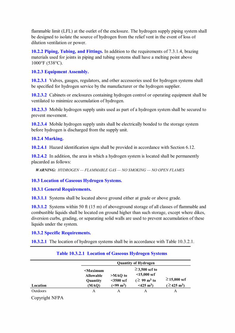
Copyright NFPA
flammable limit (LFL) at the outlet of the enclosure. The hydrogen supply piping system shall be designed to isolate the source of hydrogen from the relief vent in the event of loss of dilution ventilation or power.
10.2.2 Piping, Tubing, and Fittings. In addition to the requirements of 7.3.1.4, brazing materials used for joints in piping and tubing systems shall have a melting point above 1000°F (538°C).
10.2.3 Equipment Assembly.
10.2.3.1 Valves, gauges, regulators, and other accessories used for hydrogen systems shall be specified for hydrogen service by the manufacturer or the hydrogen supplier.
10.2.3.2 Cabinets or enclosures containing hydrogen control or operating equipment shall be ventilated to minimize accumulation of hydrogen.
10.2.3.3 Mobile hydrogen supply units used as part of a hydrogen system shall be secured to prevent movement.
10.2.3.4 Mobile hydrogen supply units shall be electrically bonded to the storage system before hydrogen is discharged from the supply unit.
10.2.4 Marking.
10.2.4.1 Hazard identification signs shall be provided in accordance with Section 6.12.
10.2.4.2 In addition, the area in which a hydrogen system is located shall be permanently placarded as follows:
WARNING: HYDROGEN — FLAMMABLE GAS — NO SMOKING — NO OPEN FLAMES
10.3 Location of Gaseous Hydrogen Systems.
10.3.1 General Requirements.
10.3.1.1 Systems shall be located above ground either at grade or above grade.
10.3.1.2 Systems within 50 ft (15 m) of aboveground storage of all classes of flammable and combustible liquids shall be located on ground higher than such storage, except where dikes, diversion curbs, grading, or separating solid walls are used to prevent accumulation of these liquids under the system.
10.3.2 Specific Requirements.
10.3.2.1 The location of hydrogen systems shall be in accordance with Table 10.3.2.1.
Table 10.3.2.1 Location of Gaseous Hydrogen Systems
Quantity of Hydrogen
Location
<Maximum Allowable Quantity (MAQ)
>MAQ to <3500 scf (<99 m 3 )
3,500 scf to <15,000 scf ( 99 m 3 to <425 m 3 )
15,000 scf ( 425 m 3 )
Outdoors A A A A

Copyright NFPA
Table 10.3.2.1 Location of Gaseous Hydrogen Systems
Quantity of Hydrogen
Location
<Maximum Allowable Quantity (MAQ)
>MAQ to <3500 scf (<99 m 3 )
3,500 scf to <15,000 scf ( 99 m 3 to <425 m 3 )
15,000 scf ( 425 m 3 )
In a detached building A A A A In a gas room, in accordance with Section 6.4
A A A Detached building required
Not in a gas room A NA NA NA A: Allowed. NA: Not allowed.
10.3.2.2 Minimum Distance.
10.3.2.2.1 The minimum distance from a hydrogen system of indicated capacity located outdoors to any specified exposure shall be in accordance with Table 10.3.2.2.1.
Table 10.3.2.2.1 Minimum Distance from Outdoor Gaseous Hydrogen Systems to Exposures
Total Gaseous Hydrogen Storage
<3500 scf (99 m 3 ) 3500 scf to 15,000 scf ( 99 m
Type of Outdoor Exposure ft m ft (1) Building or structure (A) Wall(s) adjacent to system constructed of noncombustible or limitedcombustible materials 1. Sprinklered building or structure or unsprinklered building or structure having noncombustible contents
0 0 5
2. Unsprinklered building or structure with combustible contents (a) Adjacent wall(s) with fire resistance rating less than 2 hours 0 0 10 (b) Adjacent wall(s) with fire resistance rating of 2 hours or greater 0 0 5 (B) Wall(s) adjacent to system constructed of other than noncombustible or limitedcombustible materials
10 3.1 25
(2) Wall openings (A) Not above any part of a system 10 3.1 10 (B) Above any part of a system 25 7.6 25 (3) All classes of flammable and combustible liquids above ground (A) 0–1000 gal (3785 L) 10 3.1 25 (B) In excess of 1000 gal (3785 L) 25 7.6 50 (4) All classes of flammable and combustible liquids below ground — 0–1000 gal (3785 L) (A) Tank 10 3.1 10 (B) Vent or fill opening of tank 25 7.6 25 (5) All classes of flammable and combustible liquids below ground — in excess of 1000 gal (3785 L) (A) Tank 20 6.1 20

Copyright NFPA
Table 10.3.2.2.1 Minimum Distance from Outdoor Gaseous Hydrogen Systems to Exposures
Total Gaseous Hydrogen Storage
<3500 scf (99 m 3 ) 3500 scf to 15,000 scf ( 99 m
Type of Outdoor Exposure ft m ft (B) Vent or fill opening of tank 25 7.6 25 (6) Flammable gas storage (other than hydrogen), either highpressure or lowpressure (A) 0–15,000 scf (425 m 3 ) capacity 10 3.1 25 (B) In excess of 15,000 scf (425 m 3 ) capacity 25 7.6 50 (7) Oxygen storage (A) 0–20,000 scf (566 m 3 ) Refer to NFPA 51, Standard for the Design and Installation of Oxygen–Fuel Gas Systems
for Welding, Cutting, and Allied Processes (B) More than 20,000 scf (566 m 3 ) Refer t (8) Fastburning solids such as ordinary lumber, excelsior, or paper 50 15.2 50 (9) Slowburning solids such as heavy timber or coal 25 7.6 25 (10) Open flames and welding 25 7.6 25 (11) Air compressor intakes or inlets to ventilating or airconditioning equipment
50 15.2 50
(12) Places of public assembly 25 7.6 50 (13) Public sidewalks and parked vehicles 15 4.6 15 (14) Line of adjoining property that is able to be built upon 5 1.5 5 (15) Encroachment by overhead utilities (A) Horizontal distance from the vertical plane below the nearest overhead wire of an electric trolley, train, or bus line
50 15 50
(B) Horizontal distance from the vertical plane below the nearest overhead electrical wire other than those noted above
5 1.5 5
(C) Piping containing other hazardous materials 15 4.6 15
10.3.2.2.2 The distances in numbers 1, 3 through 10, and 14 inclusive in Table 10.3.2.2.1 shall not apply where fire barrier walls having a minimum fire resistance rating of 2 hours are located between the system and the exposure.
10.3.2.2.3 Portions of wall less than 10 ft (3 m) (measured horizontally) from any part of a system shall have a fire resistance rating of at least ½ hour.
10.3.2.2.4 When determining the minimum distance between the hydrogen system and adjacent firerated walls, windows and doors shall be excluded from the fire rating determination. (See number 2 of Table 10.3.2.2.1).
10.3.2.2.5 Portions of walls less than 10 ft (3 m) (measured horizontally) from any part of a system shall have a fire resistance rating of at least 1 hour.
10.3.2.2.6 Distances shall be permitted to be reduced to 15 ft (4.5 m) for Class IIIB combustible liquids.
10.3.2.3 Unloading connections on delivery equipment shall not be positioned closer to any

Copyright NFPA
of the exposures cited in Table 10.3.2.2.1 than the distances given for the storage system.
10.4 Design Requirements at Specific Locations.
10.4.1 Outdoor Locations.
10.4.1.1 Where overhead cover is provided, it shall be in accordance with the provisions of 6.5.2.
10.4.1.2 Electrical wiring and equipment shall be in accordance with Section 6.6.
10.4.2 Detached Buildings.
10.4.2.1 Detached buildings shall be constructed of noncombustible or limitedcombustible materials in accordance with the requirements of Section 6.5.
10.4.2.2 Ventilation shall be provided in accordance with the requirements of Section 6.17.
10.4.2.2.1 Outlet openings shall be located at the high point of the room in exterior walls or roof.
10.4.2.2.2 Inlet and outlet openings shall each have a minimum total area of 1 ft 2 /1000 ft 3 (1 m 2 /305 m 3 ) of room volume.
10.4.2.2.3 Discharge from outlet openings shall be directed or conducted to the atmosphere.
10.4.2.3* Explosion control shall be provided in accordance with the requirements of Section 6.10.
10.4.2.4 Electrical equipment shall be in accordance with Article 501 of NFPA 70, National Electrical Code, for Class I, Division 2 locations.
10.4.2.5 Heating, if provided, shall be by steam, hot water, or other indirect means except that electrical heating shall be permitted to be used if in compliance with 10.4.2.4.
10.4.3 Hydrogen Gas Rooms.
10.4.3.1 Floors, walls, and ceilings shall be constructed of noncombustible or limitedcombustible materials in accordance with the requirements of NFPA 5000, Building Construction and Safety Code.
10.4.3.1.1 Interior walls or partitions shall have a fire resistance rating of not less than 2 hours, shall be continuous from floor to ceiling, and shall be anchored to resist movement.
10.4.3.1.2 Not less than 25 percent of the perimeter wall shall be an exterior wall.
10.4.3.1.3 Openings to other parts of the building shall not be permitted.
10.4.3.1.4 Windows and doors shall be in exterior walls only.
10.4.3.2 Ventilation shall be as provided in Section 6.17.
10.4.3.3 Explosion control shall be provided in accordance with the requirements of Section 6.10.
10.4.3.4 There shall be no sources of ignition from open flames, electrical equipment, or

Copyright NFPA
heating equipment.
10.4.3.5 Electrical equipment shall be in accordance with Article 501 of NFPA 70, National Electrical Code, for Class I, Division 2 locations.
10.4.3.6 Heating, if provided, shall be by steam, hot water, or indirect means except that electrical heating shall be permitted to be used if in compliance with 10.4.3.5.
10.4.4 Indoor Hydrogen System Location.
10.4.4.1 Hydrogen systems of less than 3500 scf (99 m 3 ) and greater than the MAQ, where located inside buildings, shall be located in the building so that the system will be as follows:
(1) In a ventilated area in accordance with the provisions of Section 6.16
(2) Separated from incompatible materials in accordance with the provisions of 7.1.6.1.1
(3) 25 ft (7.6 m) from open flames and other sources of ignition
(4) 50 ft (15 m) from intakes of ventilation, airconditioning equipment, and air compressors
(a) The distance is permitted to be reduced to 10 ft (3 m) where the room or area is protected by a listed detection system as per Article 500.7(K) of NFPA 70, National Electrical Code, and the detection system shall shut down the fuel supply in the event of a leak that results in a concentration that exceeds 25 percent of the LFL.
(b) Isolation valves used to isolate the fuel supply shall be of a failsafe design.
(5) 50 ft (15 m) from other flammable gas storage
(6) Protected against damage in accordance with the provisions of 7.1.6.6
10.4.4.2 More than one system of 3500 scf (99 m 3 ) or less shall be permitted to be installed in the same room or area, provided the systems are separated by at least 50 ft (15 m) or a fullheight fireresistive partition having a minimum fire resistance rating of 2 hours is located between the systems.
10.4.4.2.1 The separation distance between multiple systems of 3500 scf (99 m 3 ) or less shall be permitted to be reduced to 25 ft (7.6 m) in buildings where the space between storage areas is free of combustible materials and protected with a sprinkler system designed for Extra Hazard, Group 1 in accordance with the requirements of Section 6.10.
10.5 Operation and Maintenance.
10.5.1 Operating Instructions. For installations that require any operation of equipment by the user, the user shall be instructed in the operation of the equipment and emergency shutdown procedures. Instructions shall be maintained at the operating site at a location acceptable to the authority having jurisdiction.
10.5.2 Maintenance. Hydrogen systems installed on the premises shall be inspected annually and maintained by a qualified representative of the equipment owner.

Copyright NFPA
10.5.3 Clearance to Combustibles. Clearance to combustibles shall be in accordance with the requirements of 7.1.6.3.
10.6* Fire Protection.
Fire protection shall be in accordance with the requirements of Section 6.10.
Chapter 11 Liquefied Hydrogen Systems
11.1* General.
The storage, use, and handling of liquefied hydrogen in liquefied hydrogen storage systems shall be in accordance with the provisions of Chapters 1 through 11, as applicable.
11.1.1 Portable containers having a total liquefied hydrogen content of less than 39.7 gal (150 L) in compliance with the requirements of Chapter 8 shall not be required to comply with Chapter 11.
11.2 Design of Liquefied Hydrogen Systems.
11.2.1 Fire Protection of Structural Supports.
11.2.1.1 Steel supports in excess of 18 in. (46 cm) in height shall have a minimum 2hour fire resistance rating in accordance with ASTM E 1529, Determining the Effects of Large Hydrocarbon Pool Fires on Structural Members and Assemblies.
11.2.1.2 Containers shall be marked in accordance with the provisions of Section 8.4 and as follows: LIQUEFIED HYDROGEN — FLAMMABLE GAS
11.2.2 PressureRelief Devices. Stationary and portable containers and tanks shall be provided with pressurerelief devices in accordance with the requirements of 8.2.4 and 11.2.2.1 through 11.2.2.3.
11.2.2.1 Pressurerelief devices serving stationary containers shall be in accordance with the provisions of 8.2.4.6.1 and arranged to discharge unobstructed to the outdoors.
11.2.2.2 Hydrogen venting systems discharging to the atmosphere shall be in accordance with CGA G5.5, Hydrogen Vent Systems.
11.2.2.3 Stationary containers shall be provided with a sign, placed in proximity to the primary tank pressurerelief valve vent stack, that warns against spraying water on or into the vent opening.
11.2.3* Piping, Tubing, and Fittings.
11.2.3.1 Piping and tubing shall be in accordance with the requirements of ASME B31.3, Process Piping.
11.2.3.2 Piping or tubing used at operating temperatures below 20°F (29°C) shall be fabricated from materials meeting the impact test requirements of Chapter III of ASME B31.3, Process Piping, when tested at the minimum operating temperature to which the

Copyright NFPA
piping will be exposed when in service.
11.2.3.3 Joints in piping and tubing shall be in accordance with the requirements of ASME B31.3, Process Piping.
11.2.3.4 Brazing materials, when used, shall have a melting point above 1000°F (538°C).
11.2.3.5 Means shall be provided to minimize exposure of personnel to piping operating at low temperatures and to prevent air condensate from contacting piping, structural members, and surfaces not designed for cryogenic temperatures.
11.2.3.5.1 Insulation on piping systems used to convey cryogenic fluids shall be of noncombustible material and shall be designed to have a vaportight seal in the outer covering to prevent the condensation of air and subsequent oxygen enrichment within the insulation.
11.2.3.5.2 The insulation material and outside shield also shall be designed to prevent deterioration of the insulation due to normal operating conditions.
11.2.3.6 Uninsulated piping and equipment that operates at liquefied hydrogen temperatures shall not be installed above asphalt or other combustible materials or surfaces in order to prevent the contact of liquid air with such materials.
11.2.3.7 Drip pans shall be allowed to be installed under uninsulated piping and equipment to retain and vaporize condensed liquid air.
11.2.4 Equipment Assembly.
11.2.4.1 Installation of liquefied hydrogen systems shall be supervised by personnel knowledgeable about the applicable standards and the construction and use of the system to be installed.
11.2.4.2 Storage containers, piping, valves, regulating equipment, and other accessories shall be accessible and shall be protected against physical damage and tampering.
11.2.4.2.1 An emergency shutoff valve shall be located in liquid supply lines as close to the container as practical.
11.2.4.2.2 Containers exceeding 2000 gal (7570 L) capacity shall be provided with an automatic emergency shutoff valve.
11.2.4.2.2.1 The automatic shutoff valve shall be operated by a remotely located, manually activated shutdown control.
11.2.4.2.2.2 The shutoff valve shall be connected to the primary container by means of welded connections without the use of flanges or other appurtenances except that a manual shutoff valve equipped with welded connections is allowed to be installed immediately upstream of the automatic shutoff valve to allow for maintenance of the automatic valve.
11.2.4.2.2.3 Connections downstream of the shutoff valve shall be in accordance with ASME B31.3, Process Piping.
11.2.4.3 Cabinets or enclosures containing hydrogen control equipment shall be ventilated

Copyright NFPA
to prevent any accumulation of hydrogen gas.
11.2.5 Liquefied Hydrogen Vaporizers.
11.2.5.1* Heat supplied to a liquefied hydrogen vaporizer shall be by indirect means utilizing a transfer medium.
11.2.5.2* A lowtemperature shutoff switch or valve shall be provided in the vaporizer discharge piping to prevent flow of liquefied hydrogen downstream of the vaporizer in the event that liquid is discharged from the vaporizer.
11.2.6 Electrical Systems. Electrical wiring and equipment shall be in accordance with Table 11.2.6 and Article 501 of NFPA 70, National Electrical Code.
Table 11.2.6 Electrical Area Classification
Location Division Extent of Classified Area
Points where connections are regularly made and disconnected
1 Within 3 ft (1 m) of connection
2 Between 3 ft (1 m) and 25 ft (7.6 m) of connection
11.2.6.1 Where equipment approved for Class I, Group B atmospheres is not commercially available, the equipment used shall meet at least one of the following:
(1) Purged or ventilated in accordance with NFPA 496, Standard for Purged and Pressurized Enclosures for Electrical Equipment
(2) Intrinsically safe
11.2.6.2 Electrical equipment installed on mobile supply trucks or tank cars from which the storage container is filled shall not be subject to 11.2.6.1.
11.2.7 Bonding and Grounding. The liquefied hydrogen system shall be electrically bonded and grounded.
11.3 Location of Liquefied Hydrogen Systems.
11.3.1 General.
11.3.1.1 Stationary storage containers shall be located so that they are accessible from mobile supply equipment.
11.3.1.2* Hydrogen systems shall not be located beneath or where exposed by failure of the following:
(1) Electric power lines as follows:
(a) Not less than 50 ft (15.24 m) from the vertical plane below the nearest overhead

Copyright NFPA
wire of an electric trolley, train, or bus line
(b) Not less than 5 ft (1.524 m) from the vertical plane below the nearest overhead electrical wire
(2) Piping containing other hazardous materials
11.3.1.3 Diking shall not be used to contain a liquid hydrogen spill.
11.3.1.4 Storage sites shall be placarded as follows:
WARNING: LIQUEFIED HYDROGEN FLAMMABLE GAS NO SMOKING — NO OPEN FLAMES
11.3.2 Specific Requirements.
11.3.2.1 The location of liquefied hydrogen storage, as determined by the maximum total quantity of liquefied hydrogen, shall be in accordance with Table 11.3.2.1.
Table 11.3.2.1 Location of Liquefied Hydrogen Systems
Quantity of Hydrogen
Location
<Maxim um
Allowabl e
Quantity (MAQ)
>MAQ to 300 gal (>170.32
L to 1135.5
L)
>300 to 600 gal (>1135.5
L to 2271 L)
>600 gal (>2271 L)
Outdoors A A A A In a detached building A A A NA In a gas room A A NA NA Inside buildings not in a gas room or detached building and exposed to other occupancies
A NA NA NA
A: Allowed. NA: Not allowed.
11.3.2.2 The minimum distance from liquefied hydrogen systems of indicated capacity shall be in accordance with Table 11.3.2.2.
Table 11.3.2.2 Minimum Distance from Liquefied Hydrogen Systems to Exposures
Total Liquefied Hydrogen Storage 39.63 gal to 3500 gal
150 L to 13,250 L
3501 gal to 15,000 gal
13,251 L to 56,781 L
Type of Exposure ft m ft m 1. Building or structure (a) Wall(s) adjacent to system constructed of noncombustible or limitedcombustible materials

Copyright NFPA
Table 11.3.2.2 Minimum Distance from Liquefied Hydrogen Systems to Exposures
Total Liquefied Hydrogen Storage 39.63 gal to 3500 gal
150 L to 13,250 L
3501 gal to 15,000 gal
13,251 L to 56,781 L
Type of Exposure ft m ft m (1) Sprinklered building or structure or unsprinklered building or structure having noncombustible contents
5 1.5 5 1.5
(2) Unsprinklered building or structure with combustible contents (a) Adjacent wall(s) with fire resistance rating less than 3 hours
25 7.6 50 15
(b) Adjacent wall(s) with fire resistance rating of 3 hours or greater
5 1.5 5 1.5
(c) Wall(s) adjacent to system constructed of combustible materials (1) Sprinklered building or structure 50 15 50 15 (2) Unsprinklered building or structure 50 15 75 23 2. Wall openings (a) Operable 75 23 75 23 (b) Inoperable 25 7.6 50 15 3. Air compressor intakes or inlets for airconditioning or ventilating equipment
75 23 75 23
4. All classes of flammable and combustible liquids (above ground and vent or fill openings if below ground)
50 15 75 23
5. Between stationary liquefied hydrogen containers
5 1.5 5 1.5
6. Flammable gas storage other than hydrogen 50 15 75 23 7. Liquid oxygen storage and other oxidizers 75 23 75 23 8. Combustible solids 50 15 75 23 9. Open flames and welding 50 15 50 15 10. Places of public assembly 75 23 75 23 11. Public ways, railroads, and property lines 25 7.6 50 15 12. Inlet to underground sewers 5 1.5 5 1.5
11.3.2.2.1 The distances in numbers 1, 4, 6, 7, 8, and 11 in Table 11.3.2.2 shall be permitted to be reduced by twothirds, but not to less than 5 ft (1.5 m), for insulated portions of the system.
11.3.2.2.2* For uninsulated portions of the system, the distances shall be permitted to be reduced by the use of fire barrier walls having a fire resistance rating of not less than 2 hours when constructed in accordance with 8.6.2.1 and 11.3.2.2.
11.3.2.2.3 The protective structure or the insulated liquefied hydrogen tank shall interrupt the line of sight between uninsulated portions of the liquefied hydrogen storage system and the exposure.

Copyright NFPA
11.3.2.2.4 The fire barrier wall shall not have more than two sides at 1.57 rad (90 degree) directions, or not more than three sides with connecting angles of not less than 2.36 rad (135 degrees).
11.3.2.2.4.1* When fire barrier walls of three sides are used, piping and control systems serving stationary tanks shall be located at the open side of the enclosure created by the barrier walls to provide access for filling and ventilation.
(A) Vertical tanks shall be located at a distance not less than one tank diameter from the enclosing walls.
(B) When horizontal tanks are used, the distance to any enclosing wall shall be not less than onehalf the length of the tank.
11.3.2.2.5 In Table 11.3.2.2, the separation distances for Class IIIB combustible liquids shall be permitted to be reduced to 15 ft (4.6 m).
11.3.2.3 Unloading connections on delivery equipment shall not be positioned closer to any of the exposures cited in Table 11.3.2.2 than the distances given for the storage system.
11.3.2.4 The minimum distance of container fill connections from parked vehicles shall be 25 ft (7.6 m).
11.3.3 Installation of Liquefied Hydrogen Inside Buildings Other Than Detached Buildings and Gas Rooms. Portable liquefied hydrogen containers of 50 gal (189 L) or less capacity located as allowed in Table 11.3.2.1 and in compliance with 11.3.1 where housed inside buildings not located in a gas room and exposed to other occupancies shall comply with the following minimum requirements:
(1) Containers shall be located 20 ft (6.1 m) from all classes of flammable or combustible liquids and combustible materials such as excelsior or paper.
(2) Containers shall be located 25 ft (7.6 m) from ordinary electrical equipment and other sources of ignition including process or analytical equipment. (See Section 8.7.)
(3) Containers shall be located 50 ft (15 m) from intakes of ventilation, airconditioning equipment, or compressors.
(4) Containers shall be located 50 ft (15 m) from storage or use of other flammable gases or storage or use of incompatible gases.
(5) Containers shall be protected against physical damage in accordance with the requirements of 8.5.5.
(6) Containers shall be secured in accordance with the requirements of 8.5.3.
(7) Welding or cutting operations and smoking shall be prohibited while hydrogen is in the room, and signs shall be provided as required by 6.12.2.2.
(8) Ventilation shall be provided in accordance with the requirements of Section 6.16.
(9) Pressurerelief devices on stationary or portable containers shall be vented directly outdoors or to an exhaust hood. (See 8.2.4.6.)

Copyright NFPA
11.4 Design Considerations at Specific Locations.
11.4.1 Outdoor Locations.
11.4.1.1 Roadways and yard surfaces located below liquefied hydrogen piping as well as areas located under the fill connections and delivery vehicles' uninsulated hydrogen piping from which liquid air is able to drip shall be constructed of noncombustible materials.
11.4.1.1.1 Asphalt and bitumastic paving shall be assumed to be combustible.
11.4.1.1.2 Expansion joints and fillers used in the construction of concrete slabs shall be of noncombustible materials.
11.4.1.2 Weather protection shall be constructed in accordance with the requirements of 6.5.2 and NFPA 5000, Building Construction and Safety Code.
11.4.1.3 Lighting shall be provided for nighttime transfer operation, and supplemental lighting shall be provided when required by Section 8.11.
11.4.2 Underground Tanks. Underground tanks for the storage of liquid hydrogen shall be in accordance with this subsection.
11.4.2.1 Construction. Storage tanks for liquid hydrogen shall be designed and constructed in accordance with Section VIII of ASME Boiler and Pressure Vessel Code and shall be vacuumjacketed in accordance with 11.4.2.1.1.
11.4.2.1.1 Vacuum Jacket Construction. The vacuum jacket shall be designed and constructed in accordance with Section VIII of ASME Boiler and Pressure Vessel Code and shall be designed to withstand the anticipated loading, including loading from vehicular traffic, where applicable. Portions of the vacuum jacket installed below grade shall be designed to withstand anticipated soil, hydrostatic, and seismic loading.
11.4.2.1.1.1 Material. The vacuum jacket shall be constructed of stainless steel or other approved corrosionresistant material.
11.4.2.1.1.2 Corrosion Protection. The vacuum jacket shall be protected by an engineered cathodic protection system. A cathodic protection system maintenance schedule shall be provided and reconciled by the owner/operator. Exposed components shall be inspected at least twice a year.
11.4.2.2 Location. Tanks shall be located in accordance with 11.4.2.2.1 through 11.4.2.2.4.
11.4.2.2.1 Underground storage tanks shall not be located beneath buildings.
11.4.2.2.2 Tanks and associated equipment shall be located with respect to foundations and supports of other structures such that the loads carried by such structures cannot be transmitted to the tank.
11.4.2.2.3 The distance from any part of the tank to the nearest wall of a basement, pit, cellar, or lot line shall not be less than 10 ft (3 m).
11.4.2.2.4 A minimum distance of 1 ft (0.31 m), shell to shell, shall be maintained between adjacent underground tanks.

Copyright NFPA
11.4.2.3 Depth, Cover, and Fill. The tank shall be buried such that the top of the vacuum jacket is covered with a minimum of 1 ft (0.3 m) of earth and with concrete a minimum of 4 in. (101 mm) thick placed over the earthen cover. The concrete shall extend a minimum of 1 ft (0.3 m) horizontally beyond the footprint of the tank in all directions. Underground tanks shall be set on foundations constructed in accordance with NFPA 5000, Building Construction and Safety Code, and surrounded with not less than 6 in. (152 mm) of noncorrosive inert material.
11.4.2.3.1 The vertical extension of the vacuum jacket required for service connections shall be allowed to extend above grade.
11.4.2.4 Anchorage and Security. Tanks and systems shall be secured against accidental dislodgment due to seismic events or flooding.
11.4.2.5 Venting of Underground Tanks. Vent pipes for underground storage tanks shall be in accordance with 11.2.2.2.
11.4.2.6 Underground Liquid Hydrogen Piping. Underground liquid hydrogen piping shall be vacuumjacketed. Unjacketed piping shall not be buried and shall exit the tank annular space above grade.
11.4.2.7 Overfill Protection and Prevention Systems. An approved means or method shall be provided to prevent the overfilling of storage tanks.
11.4.2.8 Vacuum Level Monitoring. An approved monitoring method shall be provided to indicate vacuum degradation within the vacuum jacket(s).
11.4.2.9 Physical Protection. Piping and control equipment ancillary to the underground tank located above ground shall be protected from physical damage in accordance with 8.5.5.
11.4.2.10 Tanks Not in Service. Tanks not in service shall be maintained in accordance with 11.4.2.10.1.
11.4.2.10.1 Corrosion protection shall be maintained in operation.
11.4.3 Detached Buildings.
11.4.3.1 Explosion Control.
11.4.3.1.1 Detached buildings containing more than 300 gal (1136 L) of liquefied hydrogen shall be constructed of noncombustible or limitedcombustible materials in accordance with the requirements of NFPA 5000, Building Construction and Safety Code.
11.4.3.1.2 Explosion control shall be provided in accordance with the requirements of Section 6.9.
11.4.3.2 Ventilation shall be provided in accordance with the requirements of Section 6.16 and 11.4.3.2.1 through 11.4.3.2.4.
11.4.3.2.1 Inlet openings shall be located within 18 in. (0.46 m) of the floor in exterior walls only.

Copyright NFPA
11.4.3.2.2 Outlet openings shall be located at the high point of the room in exterior walls or roof.
11.4.3.2.3 Both the inlet and outlet vent openings shall have a minimum total area of 1 ft 2 /1000 ft 3 (1 m 2 /300 m 3 ) of room volume.
11.4.3.2.4 Discharge from outlet openings shall be directed or conducted to a location that allows for dissipation of the exhaust air in the ambient surroundings away from air intakes and occupied spaces.
11.4.3.3* There shall be no sources of ignition within the room or area where the hydrogen system is installed.
11.4.3.4 Heating.
11.4.3.4.1 Heating, if provided, shall be by indirect means such as steam or hot water.
11.4.3.4.2 Electrical heating in accordance with Section 8.7 shall be allowed.
11.4.4 Gas Rooms.
11.4.4.1 Heating, if provided, shall be by steam, hot water, or other indirect means.
11.4.4.2 Electrical heating in accordance with Section 8.7 shall be allowed.
11.5 Operation.
11.5.1 Securing Equipment. Mobile liquefied hydrogen supply units used as part of a hydrogen system shall be restrained to resist movement.
11.5.2 Bonding and Grounding. Mobile liquefied hydrogen supply units shall be electrically bonded and grounded.
Annex A Explanatory Material
Annex A is not a part of the requirements of this NFPA document but is included for informational purposes only. This annex contains explanatory material, numbered to correspond with the applicable text paragraphs.
A.1.1.2(1) For regulations on the transportation of gases, see 49 CFR 100 to 179 (Transportation) and Transportation of Dangerous Goods Regulations.
A.1.1.2(4) It is intended that installations of bulk oxygen systems regulated by NFPA 99 also comply with the requirements of Chapter 9 of NFPA 55. The bulk oxygen system terminates at the point where oxygen at service pressure first enters the supply line.
A.1.1.2(8) For information, see NFPA 52, Compressed Natural Gas (CNG) Vehicular Fuel Systems Code; or NFPA 58, Liquefied Petroleum Gas Code.
A.1.1.2(9) The storage of gases outside of laboratory work areas is covered by this standard.
A.1.2 Reference is made to other materialspecific standards published by NFPA when
Copyright NFPA
appropriate. The materialspecific standards are limited in number, and controls are focused on select materials through the use of these standards. On the other hand, NFPA 55 is intended to be a generic standard and applicable to all materials when found in the gaseous or cryogenic state.
A.2.3.4 Applicable equivalent regulations apply in the country of use.
A.3.2.1 Approved. The National Fire Protection Association does not approve, inspect, or certify any installations, procedures, equipment, or materials; nor does it approve or evaluate testing laboratories. In determining the acceptability of installations, procedures, equipment, or materials, the authority having jurisdiction may base acceptance on compliance with NFPA or other appropriate standards. In the absence of such standards, said authority may require evidence of proper installation, procedure, or use. The authority having jurisdiction may also refer to the listings or labeling practices of an organization that is concerned with product evaluations and is thus in a position to determine compliance with appropriate standards for the current production of listed items.
A.3.2.2 Authority Having Jurisdiction (AHJ). The phrase “authority having jurisdiction,” or its acronym AHJ, is used in NFPA documents in a broad manner, since jurisdictions and approval agencies vary, as do their responsibilities. Where public safety is primary, the authority having jurisdiction may be a federal, state, local, or other regional department or individual such as a fire chief; fire marshal; chief of a fire prevention bureau, labor department, or health department; building official; electrical inspector; or others having statutory authority. For insurance purposes, an insurance inspection department, rating bureau, or other insurance company representative may be the authority having jurisdiction. In many circumstances, the property owner or his or her designated agent assumes the role of the authority having jurisdiction; at government installations, the commanding officer or departmental official may be the authority having jurisdiction.
A.3.2.4 Listed. The means for identifying listed equipment may vary for each organization concerned with product evaluation; some organizations do not recognize equipment as listed unless it is also labeled. The authority having jurisdiction should utilize the system employed by the listing organization to identify a listed product.
A.3.3.1 Absolute Pressure. Measured from this reference point, the standard atmospheric pressure at sea level is an absolute pressure of 101.325 kPa (14.7 psia). Absolute pressure in the inchpound system is commonly denoted in terms of pounds per square inch absolute (psia).
A.3.3.18 Cylinder Pack. Sixpacks and twelvepacks are terms used to further define cylinder packs with a specific number of cylinders involved. The characteristic internal water volume of individual cylinders in a cylinder pack ranges from 1.52 ft 3 to 1.76 ft 3 (43 L to 50 L) or a water capacity of from 95 lb to 110 lb (43 kg to 50 kg).
A.3.3.25 Exhausted Enclosure. Such enclosures include laboratory hoods, exhaust fume hoods, and similar appliances and equipment used to retain and exhaust locally the gases, fumes, vapors, and mists that could be released. Rooms or areas provided with general ventilation, in and of themselves, are not exhausted enclosures.

Copyright NFPA
A.3.3.26 Explosion Control. NFPA 68, Guide for Venting of Deflagrations, provides guidance on the use of deflagration venting systems for use in buildings and other enclosures. The primary purpose of a venting system is to relieve the overpressure produced in an explosion to limit the potential damage to the building where the explosion occurs. Although some structural damage can be anticipated, the use of relief venting is expected to prevent massive building failure and collapse. In cases where detonation is probable, venting is often used in conjunction with barricade construction where the pressureresistant portions of the building have been constructed to resist the pressures anticipated should an explosive event occur. Design of barricade systems is highly specialized and the subject of military standards applicable to the subject. NFPA 69, Standard on Explosion Prevention Systems, provides guidance on the use of suppression, ventilation systems, and the limiting of oxidants as a means to prevent the occurrence of an explosion. When relief vents are to be used as a means to provide explosion relief, the fundamental requirements of NFPA 5000, Building Construction and Safety Code, for structural elements including snow, wind, and seismic events should be considered. In some instances, the requirements for wind resistance can impose more rigorous requirements on the relief vents than required by the engineering analysis used to determine the relief pressure. In such cases, users must demonstrate that the relief vents will not become airborne or release in such a manner as to create secondary hazards within or external to the building in which they are installed. Specific designs may require approval by the AHJ.
A.3.3.27 Flammable Liquid (Class I). Materials that boil at a temperature of less than 20°C (68°F) are compressed gases. Users are cautioned that the use of the definitions found in NFPA 30, Flammable and Combustible Liquids Code, can result in the misclassification of certain liquefied compressed gases as flammable liquids (Class IA). Liquefied hydrogen is classed as a flammable compressed gas by the U.S. Department of Transportation. It is regulated as a cryogenic fluid within this standard.
A.3.3.29.1 Compressed Gas. The states of a compressed gas are categorized as follows:
(1) Nonliquefied compressed gases are gases, other than those in solution, that are in a packaging under the charged pressure and are entirely gaseous at a temperature of 20°C (68°F).
(2) Liquefied compressed gases are gases that, in a packaging under the charged pressure, are partially liquid at a temperature of 20°C (68°F). Cryogenic fluids represent a transient state of a gas that is created through the use of refrigeration. Cryogenic fluids cannot exist in the liquid form or partial liquid form at temperatures of 20°C (68°F), hence, they are not “compressed gases” as defined.
(3) Compressed gases in solution are nonliquefied gases that are dissolved in a solvent.
(4) Compressed gas mixtures consist of a mixture of two or more compressed gases contained in a packaging, the hazard properties of which are represented by the properties of the mixture as a whole.
A.3.3.29.9 Other Gas. A gas classified as an “Other Gas” might be a nonflammable gas or an inert gas.

Copyright NFPA
A.3.3.29.13 Unstable Reactive Gas. Unstable reactive materials are subdivided into five classifications. Class 4 materials are materials that in themselves are readily capable of detonation or explosive decomposition or explosive reaction at normal temperatures and pressures. They include the following:
(1) Materials that are sensitive to localized thermal or mechanical shock at normal temperatures and pressures
(2) Materials that have an instantaneous power density (product of heat of reaction and reaction rate) at 250°C (482°F) of 1000 W/mL or greater
Class 3 materials are materials that in themselves are capable of detonation or explosive decomposition or explosive reaction but require a strong initiating source or heat under confinement before initiation. Class 3 materials include the following:
(1) Materials that have an instantaneous power density (product of heat of reaction and reaction rate) at 250°C (482°F) at or above 100 W/mL and below 1000 W/mL
(2) Materials that are sensitive to thermal or mechanical shock at elevated temperatures and pressures
(3) Materials that react explosively with water without requiring heat or confinement
Class 2 materials are materials that readily undergo violent chemical change at elevated temperatures and pressures, including the following:
(1) Materials that have an instantaneous power density (product of heat of reaction and reaction rate) at 250°C (482°F) at or above 10 W/mL and below 100 W/mL
(2) Materials that react violently with water or form potentially explosive mixtures with water
Class 1 materials are materials that in themselves are normally stable but that can become unstable at elevated temperatures and pressures, including the following:
(1) Materials that have an instantaneous power density (product of heat of reaction and reaction rate) at 250°C (482°F) at or above 0.01 W/mL and below 10 W/mL
(2) Materials that react vigorously with water, but not violently
(3) Materials that change or decompose on exposure to air, light, or moisture
Class 0 materials are materials that in themselves are normally stable, even under fire conditions, including the following:
(1) Materials that have an instantaneous power density (product of heat of reaction and reaction rate) at 250°C (482°F) below 0.01 W/mL
(2) Materials that do not react with water
(3) Materials that do not exhibit an exotherm at temperatures less than or equal to 500°C (932°F) when tested by differential scanning calorimetry
A.3.3.30 Gas Cabinet. Doors and access ports for exchanging cylinders and accessing

Copyright NFPA
pressureregulating controls are permitted to be included as part of a gas cabinet.
A.3.3.32 Gas Room. Gas rooms must be constructed and utilized in accordance with Section 6.4.
A.3.3.33 Gaseous Hydrogen System. The system includes stationary or portable containers, pressure regulators, pressurerelief devices, manifolds, interconnecting piping, and controls as required.
A.3.3.35 Hazard Rating. The criteria for hazard rating are as defined in NFPA 704, Standard System for the Identification of the Hazards of Materials for Emergency Response.
A.3.3.36 Immediately Dangerous to Life and Health (IDLH). This level is established by the National Institute for Occupational Safety and Health (NIOSH). If adequate data do not exist for precise establishment of IDLH data, an independent certified industrial hygienist, industrial toxicologist, or appropriate regulatory agency should make such determination.
A.3.3.37 ISO Module. The characteristic internal water volume of individual tubular cylinders is 43 ft 3 (1218 L) or a water capacity of 2686 lb (1218 kg). The frame of an ISO container module and its corner castings are specially designed and dimensioned to be used in multimodal transportation service on container ships, special highway chassis, and containeronflatcar railroad equipment.
A.3.3.38.2 Permissible Exposure Limit (PEL). The maximum permitted timeweighted average exposures to be utilized are those published in 29 CFR 1910.1000.
A.3.3.38.3 ShortTerm Exposure Limit (STEL). STEL limits are published in 29 CFR 1910.1000.
A.3.3.40 Liquefied Hydrogen System. The system includes stationary or portable containers, including unconnected reserves, pressure regulators, pressure relief devices, manifolds, interconnecting piping, and controls as required.
A.3.3.44 Mobile Supply Unit. Examples include ISO modules, tube trailers, and cylinder packs.
A.3.3.47 Normal Temperature and Pressure (NTP). There are different definitions of normal conditions. The normal conditions defined here are the ones most commonly used in the compressed gas and cryogenic fluid industry.
A.3.3.54.1 Compressed Gas System. A compressed gas system can consist of a compressed gas container or containers, reactors, and appurtenances, including pumps, compressors, and connecting piping and tubing.
A.3.3.55.1 Portable Tank. A portable tank does not include any cylinder having less than 453.5 kg (1000 lb) water capacity, cargo tank, tank car tank, or trailers carrying cylinders of over 453.5 kg (1000 lb) water capacity.
A.3.3.55.2 Stationary Tank. A stationary tank does not include a cylinder having less than 453.5 kg (1000 lb) water capacity.

Copyright NFPA
A.3.3.57 Tube Trailer. The characteristic internal water volume of individual tubular cylinders ranges from 43 ft 3 (1218 L) to 93 ft 3 (2632 L) or a water capacity of 2686 lb (1218 kg) to 5803 lb (2632 kg).
A.6.8 Under the requirements of 29 CFR 1910.38 established by OSHA regulations, employers must establish an employee alarm system that complies with 29 CFR 1910.165. The requirements of 29 CFR 1910.165 for the employee alarm system include, but are not limited to, systems that are capable of being perceived above ambient noise or light levels by all employees in the affected portions of the workplace. Tactile devices may be used to alert those employees who would not otherwise be able to recognize the audible or visual alarm. The alarm system may be electrically powered or powered by pneumatic or other means. State, local, or other governmental regulations may also establish requirements for employee alarm systems.
A.6.9 NFPA 68, Guide for Venting of Deflagrations, provides more information on this subject.
A.6.10 The intent of this section is to require a waterbased fire extinguishing system to keep vessels containing compressed gases cool in the event of an exposure fire, thereby minimizing the likelihood of a release and associated consequences. Accordingly, alternative fire extinguishing systems, such as drychemical or gaseous agent systems, should not be substituted.
A.7.1.1 The equipment referenced is intended to include fuel cell applications, generation of hydrogen from portable or transportable hydrogen generation equipment, batteries, and similar devices and equipment that utilize hydrogen for the purpose of power generation. It does not include hydrogen production facilities intended to produce hydrogen used for distribution or repackaging operations operated by gas producers, distributors, and repackagers.
A.7.1.6.2 Figure A.7.1.6.2 is a schematic showing the separation distances required under 7.1.6.2.

Copyright NFPA
FIGURE A.7.1.6.2 Separation of Gas Cylinders by Hazard.
A.7.1.10.3 The gas supplier should be consulted for advice under these circumstances.
A.7.9.3.6 The areas for typical restricted flow orifices are shown in Table A.7.9.3.6.
Table A.7.9.3.6 Typical Orifice Areas
Orifice Diameter Area cm in. cm 2 in. 2 0.015 0.006 1.83 × 10 4 2.83 × 10 5
0.025 0.010 5.06 × 10 4 7.85 × 10 5
0.036 0.014 9.93 × 10 4 1.54 × 10 4
The formula has been taken from industry publications including the Scott Specialty Gases Design and Safety Handbook. It is based on estimated flow rates for air at 21°C (70°F) discharging to normal atmospheric pressure through an average shape and quality orifice. It can be assumed to be ±15 percent accurate. Correction factors have been built into the formula as presented in 7.9.3.6.2 to accommodate the use of gases other than air (e.g., use of specific gravity data).
A.8.2 Pressure vessels of any type may be subject to additional regulations imposed by various states or other legal jurisdictions. Users should be aware that compliance with DOT or ASME requirements might not satisfy all of the required regulations for the location in which the vessel is to be installed or used. Liquid oxygen containers should be fabricated from materials meeting the impact test requirements of paragraph UG84 of the ASME Boiler and Pressure Vessel Code, Section VIII.
A.8.4.1.1.2 An example of this identification is 360 degree wraparound tape.

Copyright NFPA
A.8.12.2.5.4.1 The intent of these provisions is to make certain that the cryogenic installation is not exposed to the potential of a pool fire from the release of flammable or combustible liquids. Cryogenic fluids are not diked in order that they are allowed to dissipate should leakage occur. Studies conducted by NASA (NSS 1740.16, Safety Standard for Hydrogen and Hydrogen Systems, 1997) shows that the use of dikes around liquid hydrogen storage facilities serves to prolong groundlevel flammable cloud travel and that the dispersion mechanism is enhanced by vaporizationinduced turbulence. The travel of spilled or leaked cryogenic fluid to distances greater than a few feet from the source given the nature of the typical leak is considered to be implausible due to the character of cryogenic fluids and their ability to quickly absorb heat from the surrounding environment.
A.8.12.2.6.2 The placement of stationary containers is limited with respect to exposure hazards. Table 8.6.2 establishes the minimum separation distance between a building and any stationary tank at 0.3 m (1 ft). Additional limitations are placed on wall openings, air intakes, and other exposures. The materialspecific tables for liquid hydrogen and liquid oxygen specify increased distances according to the type of construction adjacent to the tank. A problem arises when courtyards are configured so as to interrupt the free movement of air around a tank where an asphyxiation hazard, a flammable hazard, or an oxygenenriched environment can be created.
Placement of stationary containers proximate to the wall of the building served is allowable providing the minimum separation distances for exposure hazards are met. When additional walls encroach on the installation to form a court, the focus of concern shifts away from the exposure hazards associated with the building itself to the hazards associated with personnel due to hazardous atmospheres that can be created due to the lack of free air movement and ventilation.
By specifying the minimum distance between the tank and the encroaching walls that form the court, the circulation of adequate air is ensured. Placing the tank at not less than the height of two of the three encroaching walls results in creating an opening such that the angular dimension between the top of two of the three encroaching walls and the point over which the tank is placed is not greater than 45 degrees, thereby allowing the circulation of air through the space in which the tank is installed.
A.8.12.2.6.2.1 See Figure A.8.12.2.6.2.1.

Copyright NFPA
FIGURE A.8.12.2.6.2.1 Bulk Oxygen System Located in a Courtyard.
A.9.1 Oxygen gas is colorless, odorless, tasteless, and nontoxic. It comprises about 21 percent of atmospheric air and is about 10 percent heavier than air. At atmospheric pressure and temperatures below 297°F (182.5°C) oxygen is a liquid. Oxygen is stable in both gas and liquid phases. In the absence of moisture, oxygen in the gaseous or liquid form is noncorrosive.
Oxygen is nonflammable. Ignition of combustible materials occurs more readily in an oxygenrich atmosphere than in air, and combustion proceeds at a more rapid rate, although no more total heat is released. This standard provides for the protection of the bulk oxygen system from involvement by fire from sources apart from the system itself. It is important to locate bulk oxygen systems in wellventilated locations, since oxygenrich atmospheres are able to collect temporarily in confined areas in the event of functioning of a pressurerelief device or leakage from the system.
A.9.1.1.1 For information on oxygen systems having capacities less than those stated in 3.3.10, Bulk Oxygen System, see NFPA 51, Standard for the Design and Installation of Oxygen–Fuel Gas Systems for Welding, Cutting, and Allied Processes, and NFPA 99, Standard for Health Care Facilities (Chapters 4 and 8).
A.9.2.1 Compatibility involves both combustibility and ease of ignition. Materials that burn in air will burn violently in pure oxygen at atmospheric pressure, and will burn explosively in pressurized oxygen. Also, a number of materials that do not burn in air will do so in pure oxygen or oxygenenriched atmospheres, particularly under pressure. Metals for containers and piping must be selected carefully, depending on service conditions. Various steels are able to be used for a number of applications, but some service conditions can call for other materials (typically copper or its alloys) because of their greater resistance to ignition and lower rate of combustion. Data regarding the combustibility and ease of ignition of materials is available in NFPA 53, Recommended Practice on Materials, Equipment, and Systems Used in OxygenEnriched Atmospheres.
Materials that can be ignited in air have lower ignition energies in oxygen. A number of such materials can be ignited by friction at a valve seat or stem packing or by adiabatic

Copyright NFPA
compression produced when oxygen at high pressure is rapidly introduced into a system initially at low pressure. Other recognized ignition mechanisms include particle impact, mass impact, static electric discharge, electrical arc, fresh metal exposure, resonance, and piloted ignition.
A.9.3.2 Figure A.9.3.2 serves to illustrate the separation distances between bulk oxygen systems and exposures.
FIGURE A.9.3.2 Distance Between Bulk Oxygen Systems and Exposures.
These distances do not apply where protective structures having a minimum fire resistance rating of 2 hours interrupt the line of sight between uninsulated portions of the bulk oxygen

Copyright NFPA
storage installation and the exposure. The protective structures protect uninsulated oxygen storage containers or supports, control equipment, and system piping (or parts thereof) from external fire exposure. Liquid oxygen storage containers are insulated. Such containers can provide lineofsight protection for uninsulated system components. Interruption of the line of sight means that an “eye” on any part of the uninsulated portion of the bulk oxygen storage installation cannot “see” any part of the exposure.
A.9.3.2.1 The distances required by Table 9.3.2 can be reduced when a fire barrier wall is constructed to shield the oxygen installation from the exposure as well as to limit the exposure of sensitive receptors to the effects of an incident involving the oxygen source. In most circumstances, a fire barrier wall will be needed to allow encroachment on property lines where the adjacent property is suitable for building. The separation distances given in Table 9.3.2 assume that any structure on the adjoining property does not dictate a greater distance.
A.9.4.1.3 Some materials commonly used for lowtemperature piping are austenitic chromiumnickel alloy steels, copper, coppersilicon alloys, aluminum, and some brasses and bronzes.
A.9.4.5 Bulk oxygen installations are not hazardous (classified) locations as defined by NFPA 70, National Electrical Code. The use of generalpurpose electrical wiring and equipment should be allowed unless otherwise indicated.
A.10.4.2.3 For guidance in these construction techniques, see NFPA 68, Guide for Venting of Deflagrations.
A.10.6 Hydrogen fires should not be extinguished until the supply of hydrogen has been shut off because of the danger of reignition or explosion. In the event of fire, large quantities of water have been sprayed on adjacent equipment to cool the equipment and prevent involvement in the fire. Combination fog and solid stream nozzles have been preferred to permit widest adaptability in fire control. Small hydrogen fires have been extinguished by dry chemical extinguishers or with carbon dioxide, nitrogen, and steam. Reignition is able to occur if a heated surface adjacent to the flame is not cooled with water or other means.
A.11.1 For information on gaseous hydrogen systems, see Chapter 10.
A.11.2.3 Some materials acceptable for liquefied hydrogen temperature include austenitic chromiumnickel alloys, certain copper alloys, and aluminum, which retain ductility and do not become brittle at the temperature of liquefied hydrogen.
A.11.2.5.1 To be indirect, heat must be transferred by a transfer medium such as air, steam, water, oil, or comparable heat sources. The use of direct heat transfer media including electrical sources or flame presents a potential hazard should the system overheat resulting in damage to the wall of the tubing used to construct the vaporizer.
A.11.2.5.2 The loss of heat or the withdrawal of hydrogen at a rate exceeding the design capacity of the vaporizer presents a circumstance where cryogenic fluid is transported into portions of the piping system that have been designed to contain gaseous—not liquid—hydrogen. Such an event is able to result in brittle failure of the piping system

Copyright NFPA
downstream of the vaporizer. The potential to trap liquid in parts of the system that have not been designed to accommodate liquid can result in a loss of hydrogen and the generation of hazardous conditions.
A.11.3.1.2 When locating liquefied hydrogen storage containers in proximity to all classes of aboveground flammable and combustible liquid storage or liquid oxygen storage, the liquefied hydrogen container should be on ground higher than all classes of flammable and combustible liquid storage or liquid oxygen storage, as spilled material will quickly vaporize, thereby mitigating the potential exposure hazard to the other fluids.
A.11.3.2.2.2 See NFPA 259, Standard Test Method for Potential Heat of Building Materials.
Separation distances to exposures in Table 11.3.2.2 should be measured in a direct line of sight or horizontally in the shortest path along the outside of buildings. The 5 ft (1.5 m) distance in Table 11.3.2.2 facilitates maintenance and enhances ventilation.
A.11.3.2.2.4.1 See Figure A.11.3.2.2.4.1.
FIGURE A.11.3.2.2.4.1 Schematic of ThreeSided Fire Barrier Wall Enclosure for a Hydrogen Storage System.
A.11.4.3.3 Hydrogen fires should not be extinguished until the supply of hydrogen has been shut off because of the danger of reignition or explosion. In the event of fire, large quantities of water will normally be sprayed on adjacent equipment to cool the equipment and prevent involvement in the fire. Combination fog and solid stream nozzles have been preferred to permit the widest adaptability in fire control. Small hydrogen fires have been extinguished by dry chemical extinguishers or with carbon dioxide, nitrogen, and steam. Reignition can occur if a metal surface adjacent to the flame is not cooled with water or other means.
Annex B Attended Operations
This annex is not a part of the requirements of this NFPA document but is included for informational purposes only.

Copyright NFPA
B.1 Introduction.
Section 112(r) of the Clean Air Act (CAA) mandates that the U.S. Environmental Protection Agency (EPA) promulgate a regulatory program to prevent accidental releases of regulated toxic and flammable substances and reduce the severity of releases that do occur. The rule was published on June 20, 1996, and formally appears in the Code of Federal Regulations as 40 CFR 68 and is officially titled Accidental Release Prevention Requirements: Risk Management Programs Under Clean Air Act Section 112(r)(7).
B.1.1 In addition to qualified judgment and expertise, the following three resources must be considered when selecting alternative release scenarios in evaluating the hazards of any system:
(1) The five scenarios as listed in Section 68.28 of 40 CFR 68
(2) The fiveyear accident history of all accidental releases from covered processes that resulted in deaths, injuries, or significant property damage onsite, or all known offsite deaths, injuries, evacuations, shelteringinplace, or property or environmental damage
(3) The hazard review or process hazards analysis completed as part of the required prevention program
B.1.2 The five scenarios encompassed in Section 68.28 of 40 CFR 68 of the regulation include the following:
(1) Transfer hose releases due to splits or sudden hose uncoupling (typical of delivery operations)
(2) Process piping releases from failures at flanges, joints, welds, valves and valve seals, and drains or bleeds
(3) Process vessel or pump releases due to cracks, seal failure, or drain, bleed, or plug failure
(4) Vessel overfilling and spill, or overpressurization and venting through relief valves or rupture disks
(5) Shipping container mishandling and breakage or puncturing leading to a spill
B.1.3 Based on comparable analysis, it was determined that the most likely alternative release scenario having an offsite impact from compressed gas systems would be a process piping failure that is either outdoors, or indoors and entrained into an unspecified exhaust system where either discharge results in a continuous emission resulting in a plume onsite or offsite. An accidental release of this type might occur due to mechanical failure, corrosion, failure of a piping component such as a joint or valve, or another cause.
B.1.4 The flow rate through a pipe during a release is computed based on the pressure of the container, cylinder, or tank, the liquid head (if a liquid is involved), the fluid density, the line's resistance to flow (based primarily on diameter, length, and number of bends), and the open area available to flow at the exit.

Copyright NFPA
B.2 Parameters.
Each parameter, whether selected by the user or preselected, as is typical, is explained in B.2.1 through B.2.5.
B.2.1 Container, Cylinder, or Tank Pressure. The highest normal operating pressure should be used for the tank pressure.
B.2.2 Liquid Head. The liquid head is the amount of pressure exerted by the weight of the liquid column. For most small containers and cylinders, the liquid head is normally small and can usually be ignored.
B.2.3 Fluid Density. Fluid density is the density of the fluid under consideration.
B.2.4 Line Length and Configuration. Line configuration is specific to the configuration under consideration.
B.2.5 Pipe Break Flow Area. Most piping breaks result in less than full pipe diameter being open to flow. For example, a fullguillotine break is not nearly as likely as a reduced flow area break or a small leak. It is unlikely that small leaks will have an offsite impact. Therefore, it is appropriate to select as an alternative release case, a piping failure characterized by a fraction of the fullopen area that is typical of the majority of piping failures while significantly greater than that of a small leak.
For the purposes of calculation, a 20 percent flow rate versus a full bore line break should be used. Statistics indicate that piping failures of this magnitude would be expected to occur between 2 and 10 times as often as a fullguillotine break.
B.3
Calculations to demonstrate the “maximum credible worstcase leak” must be engineered and factors to include the nature of flow must be considered, including whether the gas or vapor flowing is gaseous, liquid, or a twophasetype flow. Detailed air dispersion models and methods of calculation are available. The choice of the model or methodology, or both, must be established by engineering principles and applied by those versed in such matters.
Annex C Physical Properties of Gaseous Hydrogen
This annex is not a part of the requirements of this NFPA document but is included for informational purposes only.
C.1 Physical Properties (Informative).
Hydrogen is a flammable gas. It is colorless, odorless, tasteless, and nontoxic. It is the lightest gas known, having a specific gravity of 0.0695 (air = 1.0). Hydrogen diffuses rapidly in air and through materials not normally considered porous.
C.1.1 Hydrogen burns in air with a pale blue, almost invisible flame. At atmospheric pressure, the ignition temperature of hydrogen–air mixtures has been reported by the U.S.
Copyright NFPA
Bureau of Mines to be as low as 932°F (500°C). The flammable limits of hydrogen–air mixtures depend on pressure, temperature, and watervapor content. At atmospheric pressure the flammable range is approximately 4 percent to 75 percent by volume of hydrogen in air.
C.1.2 Hydrogen remains as a gas even at high pressures. It is liquefied when it is cooled to its boiling point of 423°F (253°C).
C.1.3 Hydrogen is nontoxic, but is able to cause anoxia (asphyxiation) when it displaces the normal 21 percent oxygen in a confined area without ventilation that will maintain an oxygen content exceeding 19.5 percent. Because hydrogen is colorless, odorless, and tasteless, its presence cannot be detected by the human senses.
C.2 Physical Properties.
Liquefied hydrogen is transparent, odorless, and not corrosive or noticeably reactive. The boiling point at atmospheric pressure is 423°F (253°C). It is only as heavy as water. In converting liquefied hydrogen to gaseous hydrogen at standard conditions, it expands approximately 850 times.
C.2.1 Hydrogen burns in air with a pale blue, almost invisible flame. At atmospheric pressure the ignition temperature of hydrogen–air mixtures has been reported by the U.S. Bureau of Mines to be as low as 932°F (500°C). The flammable limits of hydrogen–air mixtures depend upon pressure, temperature, and watervapor content. At atmospheric pressure the flammable range is approximately 4 percent to 75 percent by volume of hydrogen in air.
C.2.2 Hydrogen is nontoxic, but can cause anoxia (asphyxiation) when it displaces the normal 21 percent oxygen in a confined area without adequate ventilation. Because hydrogen is colorless, odorless, and tasteless, its presence cannot be detected by the human senses.
Annex D Informational References
D.1 Referenced Publications.
The following documents or portions thereof are referenced within this standard for informational purposes only and are thus not part of the requirements of this document unless also listed in Chapter 2.
D.1.1 NFPA Publications. National Fire Protection Association, 1 Batterymarch Park, Quincy, MA 021697471.
NFPA 30, Flammable and Combustible Liquids Code, 2003 edition.
NFPA 51, Standard for the Design and Installation of Oxygen–Fuel Gas Systems for Welding, Cutting, and Allied Processes, 2002 edition.
NFPA 52, Compressed Natural Gas (CNG) Vehicular Fuel Systems Code, 2002 edition.
NFPA 53, Recommended Practice on Materials, Equipment, and Systems Used in

Copyright NFPA
OxygenEnriched Atmospheres, 2004 edition.
NFPA 58, Liquefied Petroleum Gas Code, 2004 edition.
NFPA 68, Guide for Venting of Deflagrations, 2002 edition.
NFPA 69, Standard on Explosion Prevention Systems, 2002 edition.
NFPA 70, National Electrical Code ® , 2002 edition.
NFPA 99, Standard for Health Care Facilities, 2005 edition.
NFPA 259, Standard Test Method for Potential Heat of Building Materials, 2003 edition.
NFPA 704, Standard System for the Identification of the Hazards of Materials for Emergency Response, 2001 edition.
NFPA 5000 ® , Building Construction and Safety Code ® , 2003 edition.
D.1.2 Other Publications.
D.1.2.1 ASME Publication. American Society of Mechanical Engineers, Three Park Avenue, New York, NY 100165990.
ASME International, Boiler and Pressure Vessel Code, “Rules for the Construction of Unfired Pressure Vessels,” Section VIII, 2001.
D.1.2.2 ASTM Publication. American Society for Testing and Materials, 100 Barr Harbor Drive, West Conshohocken, PA 19428–2959.
ASTM E 136–96a, Standard Method of Test for Behavior of Materials in a Vertical Tube Furnace at 750°C, 1988.
D.1.2.3 CTC Publication. Canadian Transport Commission, Queen's Printer, Ottawa, Ontario, Canada.
(Available from the Canadian Communications Group Publication Centre, Ordering Department, Ottawa, Ontario, Canada K1A 0S9.)
Transportation of Dangerous Goods Regulations.
D.1.2.4 U.S. Government Publications. U.S. Government Printing Office, Washington, DC 20402.
NSS 1740.16, Safety for Hydrogen and Hydrogen Systems, 1997.
Title 16, Code of Federal Regulations, Part 1500.41.
Title 16, Code of Federal Regulations, Part 1500.42.
Title 29, Code of Federal Regulations, Part 1910.38.
Title 29, Code of Federal Regulations, Part 1910.1000.
Title 29, Code of Federal Regulations, Part 1910.165.
Title 29, Code of Federal Regulations, Part 191.1200.

Copyright NFPA
Title 40, Code of Federal Regulations, Part 68.
Title 49, Code of Federal Regulations, Parts 100–179.
D.1.2.5 Other Publications.
Design and Safety Handbook, Scott Specialty Gases, Plumsteadville, PA, 2004.
MerriamWebster's Collegiate Dictionary, 11th edition, MerriamWebster Inc., Springfield, MA, 2003.
D.2 Informational References.
The following documents or portions thereof are listed here as informational resources only. They are not a part of the requirements of this document.
NFPA 68, Guide for Venting of Deflagrations, 2002 edition.
D.3 References for Extracts.
The following documents are listed here to provide reference information, including title and edition, for extracts given throughout the nonmandatory sections of this standard as indicated by a reference in brackets [ ] following a section or paragraph. These documents are not a part of the requirements of this document unless also listed in Chapter 2 for other reasons.
NFPA 1, Uniform Fire Code™, 2003 edition.
NFPA 57, Liquefied Natural Gas (LNG) Vehicular Fuel Systems Code, 2002 edition.
NFPA 58, Liquefied Petroleum Gas Code, 2004 edition.
NFPA 101 ® , Life Safety Code ® , 2003 edition.
NFPA 220, Standard on Types of Building Construction, 1999 edition.
NFPA 318, Standard for the Protection of Semiconductor Fabrication Facilities, 2002 edition.
NFPA 5000 ® , Building Construction and Safety Code ® , 2003 edition.
Formal Interpretation

Copyright NFPA


![Second Revision No. 3-NFPA 53-2020 [ Detail ]](https://static.fdokumen.com/doc/165x107/631ed16a1aedb9cd850fee3c/second-revision-no-3-nfpa-53-2020-detail-.jpg)


