Comprehensive Conservation Plans provide long ... - CiteSeerX
Upload
khangminh22Category
view
0download
0
MASTER-K 2001 / Nov. 2002 Printed in Korea staff
MK 문표지 2004.3.12 10:10 AM 페이지1
2
Newly designed MASTER-K series provide open distributed
Smallest Micro PLC(W120×H80×D65mm)Program Capacity : 800 StepsI/O Points : 14 (I/O=8/6)Built-in High Speed Counter(1Phase, 8K pps)RS-232C/RS-485 Interface up to32 CPUs linked via RS-485 Interface
High Speed Performance : 0.5㎲/StepCompact SizeProgram Capacity : 7K StepsI/O Points : 10~80 PointsExpansion Unit : 10 PointsBuilt-in Special Functions - PID Control, High Speed Counter, Pulse OutputRS-232Port, Input Filter, Pulse Catch
Special Function Modules- Analog I/Os, Analog TimerCommunication Modules- RS-232C, RS-422/485 (Modbus, AB DF1 Protocol available)
Number : E124950
3
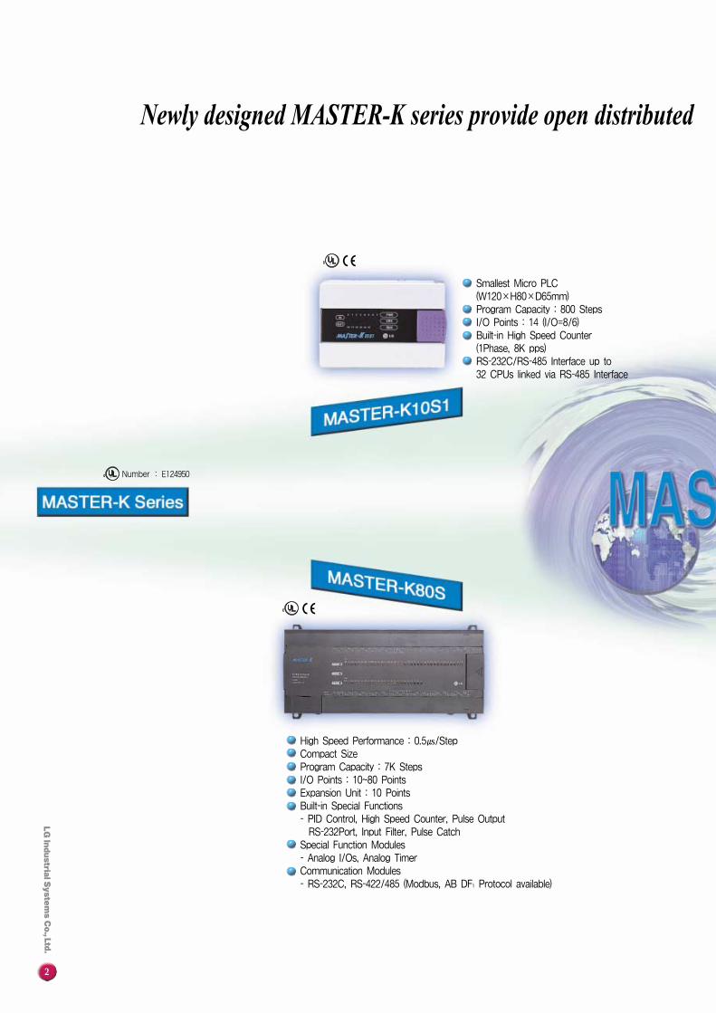
automation solutions. MASTER-K Series
4
6
8
12
14
MASTER-K Series
K10S1
K80S
K300S
18 MASTER-K Fnet (Fieldbus) System
20 MASTER-K Cnet System
22 Analog Input Modules
23 Analog Output Modules
24 Thermocouple Input Modules
25 RTD Control Modules
26 PID Control Modules
27 High Speed Counter Modules
28 Position Control Modules
30 Analog Timer Modules
32 Hand Held Loader Code List
33 Graphic Loader
34 Monitoring System (PMU Series)
36 Products List
K200S
C O N T E N T S
High Speed Performance (0.5㎲/Step)Program Capacity : 7K StepsI/O Points : Up to 384Special Function Modules- Analog I/Os, High Speed Counter, Position Control ModulesCommunication Modules- RS-232C, RS-422/485 (Modbus, AB DF1 Protocol available),Fieldbus (Fnet)
On-line EditingVarious Debugging and Self-Diagnosis- Sampling Trace & Trigger Functions
High Speed Performance : 0.2㎲/StepProgram Capacity : 15K StepsI/O Points : Up to 512Various Special Function Modules- Analog I/Os, PID, RTD, TC, HSC, Positioning ModulesCommunication Modules- RS-232C, RS-422/485 (Modbus, AB DF1 Protocol available),Fieldbus (Fnet)
On-line EditingVarious Debugging and Self-Diagnosis- Sampling Trace & Trigger Functions
4
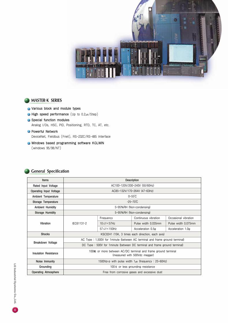
Items
Rated Input Voltage
Operating Input Voltage
Ambient Temperature
Storage Temperature
Ambient Humidity
Storage Humidity
Vibration
Shocks
Breakdown Voltage
Insulation Resistance
Noise Immunity
Grounding
Operating Atmosphere
Description
AC100~120V/200~240V (50/60Hz)
AC85~132V/170~264V (47~63Hz)
0~55℃
-25~70℃
5~95%RH (Non-condensing)
5~95%RH (Non-condensing)
Frequency Continuous vibration Occasional vibration
IEC61131-2 10≤f�57Hz Pulse width 0.035mm Pulse width 0.075mm
57≤f�150Hz Acceleration 0.5g Acceleration 1.0g
KSC0241 (15K, 3 times each direction, each axis)
AC Type : 1,500V for 1minute (between AC terminal and frame ground terminal)
DC Type : 500V for 1minute (between DC terminal and frame ground terminal)
100㏁ or more between AC/DC terminal and frame ground terminal
(measured with 500Vdc megger)
1500Vp-p with pulse width 1㎲ (frequency : 25~60Hz)
100Ϊ or less grounding resistance
Free from corrosive gases and excessive dust
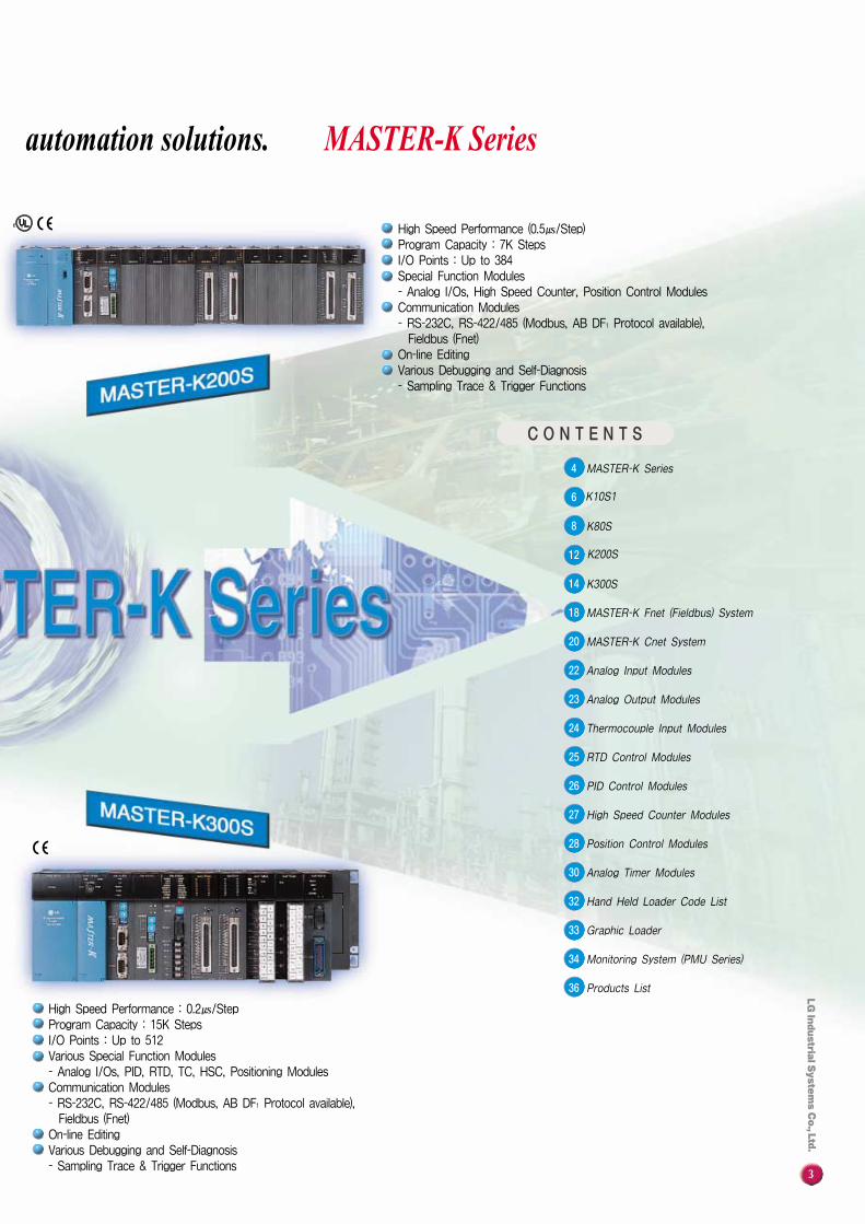
VVaarriioouuss bblloocckk aanndd mmoodduullee ttyyppeess
HHiigghh ssppeeeedd ppeerrffoorrmmaannccee (Up to 0.2㎲/Step)
SSppeecciiaall ffuunnccttiioonn mmoodduulleess
Analog I/Os, HSC, PID, Positioning, RTD, TC, AT, etc.
PPoowweerrffuull NNeettwwoorrkk
DeviceNet, Fieldbus (Fnet), RS-232C/RS-485 Interface
WWiinnddoowwss bbaasseedd pprrooggrraammmmiinngg ssooffttwwaarree KKGGLLWWIINN
(windows 95/98/NT)
MASTER-K SERIES
General Specification
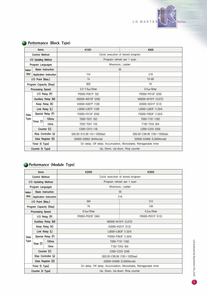
Performance (Block Type)
5
Items
Control Method
I/O Updating Method
Program Languages
Basic Instruction
Application Instruction
I/O Point (Max.)
Program Capacity (Step)
Processing Speed
I/O Relay (P)
Auxiliary Relay (M)
Keep Relay (K)
Link Relay (L)
Special Relay (F)
100ms
10ms
Counter (C)
Step Controller (s)
Data Register (D)
Timer (5 Type)
Counter (4 Type)
K10S1 K80S
Cyclic execution of stored program
Program refresh per 1 scan
Mnemonic, Ladder
30Instruc-tions
Timer (T)
14
800
3.2~7.6㎲/Step
P0000~P001F (32)
M0000~M015F (256)
K0000~K007F (128)
L0000~L007F (128)
F0000~F015F (256)
T000~T031 (32)
T032~T047 (16)
C000~C015 (16)
S00.00~S15.99 (16×100Step)
D0000~D0063 (64Words)
10~80
7K
0.5㎲/Step
P0000~P015F (256)
M0000~M191F (3,072)
K0000~K031F (512)
L0000~L063F (1,024)
F0000~F063F (1,024)
T000~T191 (192)
T192~T255 (64)
C000~C255 (256)
S00.00~C99.99 (100×100Step)
D0000~D4999 (5,000Words)
On delay, Off delay, Accumulation, Monostable, Retriggerable timer
Up, Down, Up-down, Ring counter
218154
DataType
Performance (Module Type)
Items
Control Method
I/O Updating Method
Program Languages
Basic Instruction
Application Instruction
I/O Point (Max.)
Program Capacity (Step)
Processing Speed
I/O Relay (P)
Auxiliary Relay (M)
Keep Relay (K)
Link Relay (L)
Special Relay (F)
100ms
10ms
Counter (C)
Step Controller (s)
Data Register (D)
Timer (5 Type)
Counter (4 Type)
K200S K300S
Cyclic execution of stored program
Program refresh per 1 scan
Mnemonic, Ladder
30
218
Instruc-tions
Timer (T)
384
7K
0.5㎲/Step
P0000~P023F (384)
512
15K
0.2㎲/Step
P0000~P031F (512)
M0000~M191F (3,072)
K0000~K031F (512)
L0000~L063F (1,024)
F0000~F063F (1,024)
T000~T191 (192)
T192~T255 (64)
C000~C255 (256)
S00.00~C99.99 (100×100Step)
D0000~D4999 (5,000Words)
On delay, Off delay, Accumulation, Monostable, Retriggerable timer
Up, Down, Up-down, Ring counter
DataType

6
System Configuration
ItemsSpecification
Control Method
I/O Updating Method
Program Languages
InstructionsBasic Instructions
Application Instructions
Processing speed
Program Capacity
Data Type
I/O Relay (P)
Auxiliary Relay (M)
Keep Relay (K)
Link Relay (L)
Special Relay (F)
Timer (T)100ms
10ms
Counter (C)
Step Controller (S)
Data Register (D)
Timer (5 Type)
Counter (4 Type)
Serial Interface
K10S1
Cyclic execution of stored program
Program refresh per 1 scan
Mnemonic, Ladder
30
154
3.2~7.6㎲/Step
800Steps
P000~P01F (32)
M000~M15F (256)
K000~K07F (128)
L000~L07F (128)
F000~F15F (256)
T000~T031 (32)
T032~T047 (16)
C000~C015 (16)
S00.00~S15.99 (16X100Step)
D000~D063 (64Words)
On delay, Off delay, Accumulation, Monostable, Retriggerable timer
Up, Down, Up-down, Ring counter
RS-232C : 9,600bps, RS-485 : 300~19,200 bps, 32 Stations, 500m
SSmmaalllleesstt mmiiccrroo -- PPLLCC
KK1100SS11 BBaassee : 14 (I/O=8/6)
SSiizzee : 120W×80H×65D
BBuuiilltt--iinn hhiigghh ssppeeeedd ccoonnuutteerr
CCoouunnttiinngg ssppeeeedd : Max. 8K pps
EEEEPPRROOMM
No battery back-up is required
PPoowweerrffuull nneettwwoorrkk
Built-in RS-232C/RS-485 Interface
Feature
Listed

7
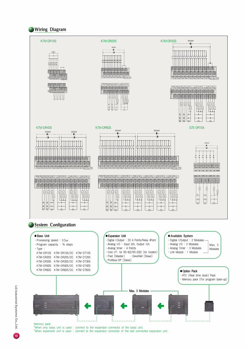
Wiring Diagram
Network System
I/O Specification
Type Input Output
AC100~240V (Free), (DC : DC24V Input)
8
6
DC24V
─
7±2mA
─
5ms or less
7ms or less
8 Point/1com
─
Photo coupler
6
4
─
AC220V, DC24V
─
2A/Point, 3A/1com
10ms or less
10ms or less
2 Point/1com
1 Point/1com
Relay
Items
Power Supply
Rated Voltage
Rated Current
Response Time
Common Method
Base
Expansion
Input
Output
Input
Output
Off→On
On→Off
Base
Expansion
Type
Insulation Device
I/O Points
HSC POO P01 P02 P03 P04 P05 P06��
P07 COM 24V OUT
PWR
ERR
RUN
IN
OUT
0 1 2 3 4 5 6 7
10 11 12 13 14 15
AC AC FG NC COM1 P10 P11 COM2 P12 P13 COM3 P14 P15100-240VAC
L L L L L L
Relay KK1100SS11
DC24V OutputHigh Speed Counter
Power : AC100~240V FG
Master PLC
Station No.
h1F
RS485 Port.
+ -
Slave PLC1
Station No.
h00
RS485 Port.
+ -
Slave PLC2
Station No.
h01
RS485 Port.
+ -
Slave PLC30
Station No.
h29
RS485 Port.
+ -
Max. 32 Stations
�Easy and simple RS-485 communication using SEND, RECV Instructions.
SEND. �FUN(159)�: Transmission data from master to slaveRECV.�FUN(158)�: Receivins data from slave to master
. . . . . .

8
Items Specification
Program Control Method
Programming Languages
No. ofInstructions
Basic
Application
Processing Speed
Program Capacity
Data Memory
I/O Area (P)
Aux. Area (M)
Keep Area (K)
Link Area (L)
Special Area (F)
Timer (T)
Counter (C)
Step Control Area (S)
Data Register (D)
PID Control
Cnet I/F Function (RS-232C)
Counting Speed
Counting Modes
Multiplication
Pulse Catch
Pulse Output
External Interrupt
Input filter
Built-in SpecialFunction
HighSpeedCounter
Mnemonic, Ladder diagram
30
218
0.5㎲/Step
7K Steps
M0000~M191F
K0000~K031F
L0000~L063F
F0000~F063F
100ms : T000~T191
10ms : T192~T255
C000~C255
S00.00~S99.99
D0000~D4999
1 Phase : 16kHz (1 channel)
2 Phase : 8kHz (1 channel)
3 Counting Modes
- 1 Phase, Up/down count with program Input
- 1 Phase, Up/down count with B phase Input
- 2 Phase, Up/down count with phase difference
P0000~P013F
Select one of 1, 2, or 4
Pulse width : 0.2ms, 8 Points
1×2kHz (Transistor output only)
8 Points, 0.4ms
0~15ms
*Remark : K7M - DR10S(/DC), K7M-DT10 : not available for Cnet I/F modules
Feature
System Configuration
I/O Updating Method Refresh Method, Direct I/O method
CCoommppaacctt ssiizzee aanndd hhiigghh ffuunnccttiioonn ttyyppee- Base : 10, 20, 30, 40, 60 Points- Expansion : 10 Points
VVaarriioouuss bbuuiilltt--iinn ffuunnccttiioonn ffoorr aapppplliiccaattiioonnss- One(1) High Speed Counter(1 Phase 16kHz, 2 Phases 8kHz)
- One(1) Pulse Train Output(2kHz)- Eight(8) PID Control with Auto Tuning- Eight(8) Pulse catch- One(1) RS-232C I/F(Dedicated, User Defined, Modbus Protocol)
VVaarriioouuss ssppeecciiaall ffuunnccttiioonn mmoodduulleess- Analog I/Os, Cnet I/F, Analog timer
RRTTCC PPaacckk,, MMeemmoorryy ppaacckk((ooppttiioonn))
OOnn--lliinnee EEddiittiinngg
Controlled by instruction, Auto tuning, Forward/Reverse action, Forced output, Operation scan time setup
Dedicated protocol, MODBUS protocol, User-defined protocol
*Remark K7M-DR10S(/DC), K7M-DT10S: Built-in RS232C and RS-485 I/F
Cyclic operation of stored program, Interrupt task operation
Listed
9
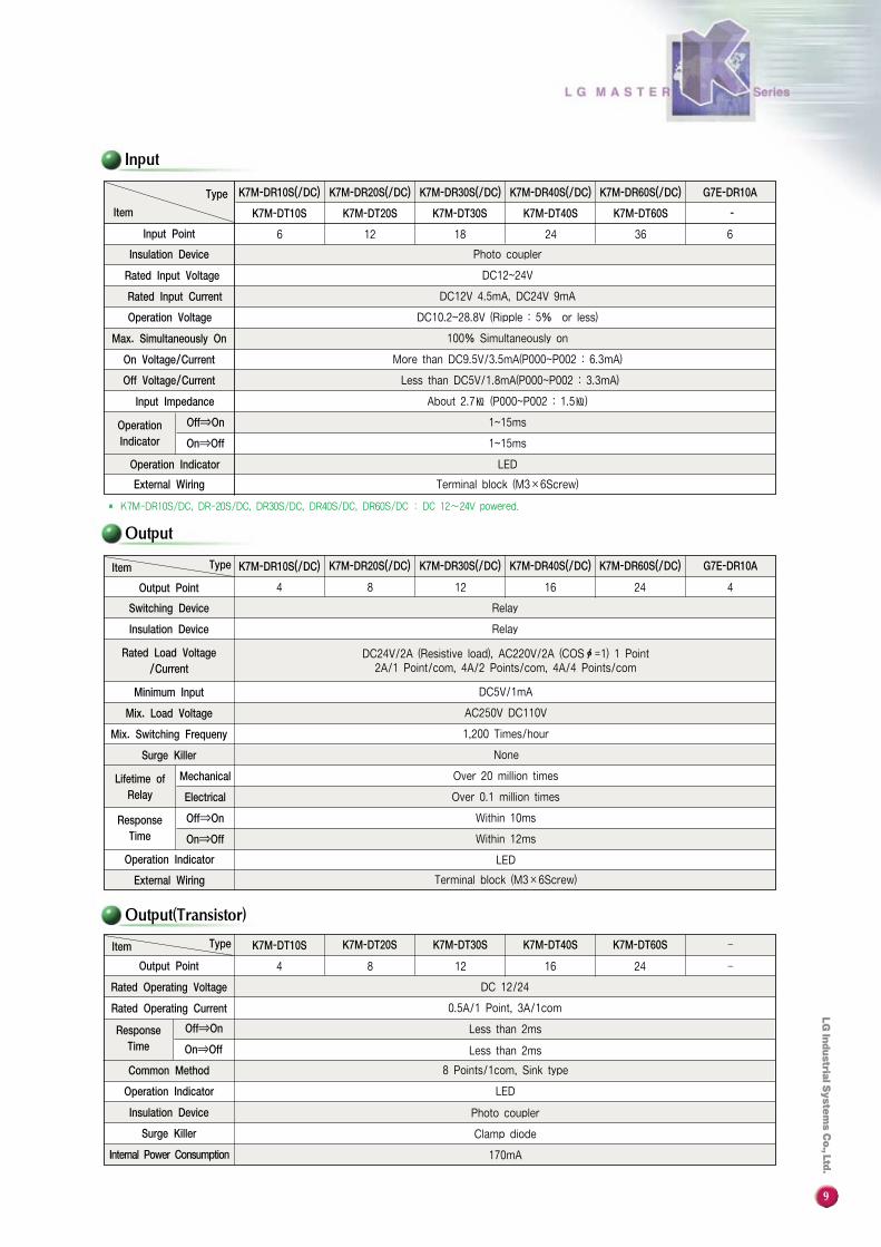
DC12~24V
170mA
LED
Terminal block (M3×6Screw)
K7M-DR40S(/DC)
Rated Operating Current
Item K7M-DT10S K7M-DT20S K7M-DT30S K7M-DT40S K7M-DT60S
4 8 12
DC 12/24
0.5A/1 Point, 3A/1com
16 24
‐
‐
Type
Less than 2ms
Less than 2ms
8 Points/1com, Sink type
LED
Photo coupler
Clamp diode
170mA
Output Point
Rated Operating Voltage
Operation Indicator
Common Method
Surge Killer
Insulation Device
Off⇒On
On⇒Off
ResponseTime
Internal Power Consumption
Output
Input
Input Point
Insulation Device
Rated Input Voltage
Rated Input Current
Operation Voltage
Max. Simultaneously On
On Voltage/Current
Off Voltage/Current
Input Impedance
Off⇒OnOperationIndicator On⇒Off
Operation Indicator
External Wiring
� K7M-DR10S/DC, DR-20S/DC, DR30S/DC, DR40S/DC, DR60S/DC : DC 12~24V powered.
K7M-DR10S(/DC) K7M-DR20S(/DC) K7M-DR30S(/DC) K7M-DR60S(/DC)
Photo coupler
DC12V 4.5mA, DC24V 9mA
DC10.2~28.8V (Ripple : 5% or less)
100% Simultaneously on
More than DC9.5V/3.5mA(P000~P002 : 6.3mA)
Less than DC5V/1.8mA(P000~P002 : 3.3mA)
About 2.7㏀ (P000~P002 : 1.5㏀)
1~15ms
1~15ms
6 12 18 24 36
G7E-DR10A
K7M-DT10S K7M-DT20S K7M-DT30S K7M-DT40S K7M-DT60S -
6
Item
Output Point
Switching Device
Insulation Device
Rated Load Voltage/Current
Minimum Input
Mix. Load Voltage
Mix. Switching Frequeny
Surge Killer
K7M-DR10S(/DC) K7M-DR20S(/DC) K7M-DR30S(/DC) K7M-DR40S(/DC) K7M-DR60S(/DC)
4 8 12
Relay
Relay
16 24
G7E-DR10A
4
Type
Off⇒OnResponseTime On⇒Off
Operation Indicator
External Wiring
MechanicalLifetime ofRelay Electrical
DC24V/2A (Resistive load), AC220V/2A (COSф=1) 1 Point2A/1 Point/com, 4A/2 Points/com, 4A/4 Points/com
DC5V/1mA
AC250V DC110V
1,200 Times/hour
None
Over 20 million times
Over 0.1 million times
Within 10ms
Within 12ms
LED
Terminal block (M3×6Screw)
Output(Transistor)
Item
Type
10
P00P01
P40 P41 P42 P44 P46P47P45P43
P03 P05 P07 P09 P0BP02 P04 P06 P08 P0A OUT
AC100FG Com0 Com1 Com2 Com3
240U P40
P00 P02P01 P03 P05
P04
P41 P42 P43
P00P01
P40 P41 P42 P44 P46 P48 P4AP43 P45 P47 P49 P4B
P03 P05 P07 P09 P0B P0D P0F P11P02 P04 P06 P08 P0A P0C P0E P10
P00 P02 P04 P06 P08 P0A P0D P0F P11 P13 P15 P17P01 P03 P05 P07 P09 P0B P0C P0E P10 P12 P14 P16
P40 P41 P42 P44 P46 P48 P4A P4C P4EP43 P45 P47 P49 P4B P4D P4F
P00 P02 P04 P06 P08 P0A P0C P0E P10 P13 P15 P17 P19 P1B P1D P1F P21 P23P01 P03 P05 P07 P09 P0B P0D P0F P11 P12 P14 P16 P18 P1A P1C P1E P20 P22
P40 P41 P42 P44 P46 P48 P4A P4C P4E P50 P52 P54 P56P43 P45 P47 P49 P4B P4D P4F P51 P53 P55 P57
100 101 102 103 104 105 COMO
000 COM1 001 COM2 002 003COMO
K7M-DR20S K7M-DR30S
K7M-DR40S K7M-DR60S G7E-DR10A
Wiring Diagram
K7M-DR10S
System Configuration
� � �
Max. 3 Modules
●Base Unit∙Processing speed : 0.5㎲
∙Program capacity : 7k steps
∙Type :
K7M-DR10S K7M-DR10S/DC K7M-DT10S
K7M-DR20S K7M-DR20S/DC K7M-DT20S
K7M-DR30S K7M-DR30S/DC K7M-DT30S
K7M-DR40S K7M-DR40S/DC K7M-DT40S
K7M-DR60S K7M-DR60S/DC K7M-DT60S
Memory pack*When only basic unit is used : connect to the expansion connector of the basic unit.*When expansion unit is used : connect to the expansion connector of the last connected expansion unit.
●Available System∙Digital I/Output : 2 Modules∙Analog I/O : 2 Modules∙Analog Timer : 3 Modules∙Link Module : 1 Module
●Expansion Unit∙Digital I/Output : DC 6 Points/Relay 4Point∙Analog I/O : Input 2ch, Output 1ch. ∙Analog timer : 4 Points∙Cnet I/F: for RS-422/RS-232C (for modem)∙Fnet (Master) ∙DevicNet (Slave) ∙Profibus-DP (Slave)
●Option Pack∙RTC (Real time clock) Pack∙Memory pack (For program back-up)
Max. 3Modules
11
Dedicated Mode
KGMWIN ModeModbus ModeUser ModeDate BitStop BitStart BitParity
Interface
SynchronizationTransmission SpeedSetting Method
Max. Cable LengthWeight
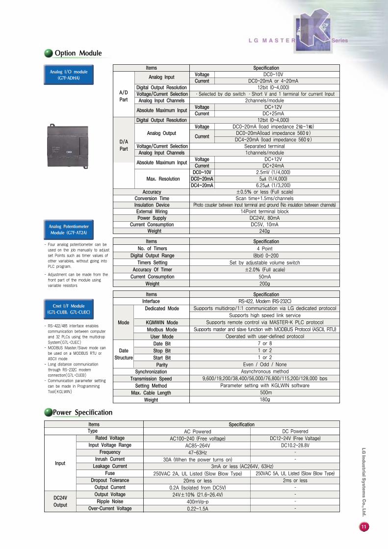
Power Specification
Analog Input VoltageCurrent
Digital Output ResolutionVoltage/Current SelectionAnalog Input Channels
Absolute Maximum InputVoltageCurrent
Digital Output Resolution
Analog OutputVoltage
Current
Voltage/Current SelectionAnalog Input Channels
Absolute Maximum InputVoltageCurrentDC0~10VDC0~20mADC4~20mA
Items
A/DPart
D/APart
Max. Resolution
AccuracyConversion TimeInsulation DeviceExternal WiringPower Supply
Current ConsumptionWeight
Specification
4 Point
(8bit) 0~200
Set by adjustable volume switch
±2.0% (Full acale)
50mA
200g
No. of TimersDigital Output Range
Timers SettingAccuracy Of TimerCurrent Consumption
Weight
DateStructure
Option Module
Analog PotentiometerModule (G7F-AT2A)
Cnet I/F Module(G7L-CUEB, G7L-CUEC)
Analog I/O module(G7F-ADHA)
Items Specification
RS-422, Modem (RS-232C)
Supports multidrop/1:1 communication via LG dedicated protocol
Supports high speed link service
Supports remote control via MASTER-K PLC protocol
Supports master and slave function with MODBUS Protocol (ASCII, RTU)
Operated with user-defined protocol
7 or 8
1 or 2
1 or 2
Even / Odd / None
Asynchronous method
9,600/19,200/38,400/56,000/76,800/115,200/128,000 bps
Parameter setting with KGLWIN software
500m
180g
Items Specification
Mode
Items
- Four analog potentiometer can beused on the job manually to adjust set Points such as timer values ofother variables, without going intoPLC program.
- Adjustment can be made from thefront part of the module using variable resistors
- RS-422/485 interface enables communication between computerand 32 PLCs using the multidrop System(G7L-CUEC)
- MODBUS Master/Slave mode canbe used on a MODBUS RTU or ASCII mode
- Long distance communicationthrough RS-232C modem connection(G7L-CUEB)
- Communication parameter setting can be made in Programming Tool(KGLWIN)
TypeRated Voltage
Input Voltage RangeFrequency
Inrush CurrentLeakage Current
FuseDropout ToleranceOutput CurrentOutput VoltageRipple Noise
Over-Current Voltage
DC24VOutput
Input
AC Powered
AC100~240 (Free voltage)
AC85~264V
47~63Hz
30A (When the power turns on)
250VAC 2A, UL Listed (Slow Blow Type)
20ms or less
0.2A (Isolated from DC5V)
24V±10% (21.6~26.4V)
400mVp-p
0.22~1.5A
3mA or less (AC264V, 63Hz)
SpecificationDC Powered
DC12~24V (Free Valtage)
DC10.2~28.8V
-
-
250VAC 5A, UL Listed (Slow Blow Type)
2ms or less
-
-
-
-
DC0~10VDC0~20mA or 4~20mA
12bit (0~4,000)∙Selected by dip switch ∙Short V and 1 terminal for current Input
2channels/moduleDC+12VDC+25mA
12bit (0~4,000)DC0~20mA (load impedance 2㏀~1㏁)DC0~20mA(load impedance 560Ϊ)DC4~20mA (load impedance 560Ϊ)
Separated terminal1channels/module
DC+12VDC+24mA
2.5mV (1/4,000)5㎂ (1/4,000)
6.25㎂ (1/3,200)±0.5% or less (Full scale)Scan time+1.5ms/channels
Photo coupler between Input terminal and ground (No insulation between channels)14Point terminal block
DC24V, 80mA DC5V, 10mA
240g
12
System Configuration
ItemsSpecification
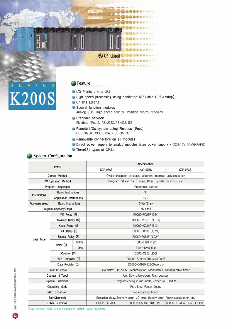
K3P-07AS
Control Method
I/O Updating Method
Program Languages
InstructionsBasic Instructions
Application Instructions
Basic Instructions
Program Capacity(Step)
Data Type
I/O Relay (P)
Auxiliary Relay (M)
Keep Relay (K)
Link Relay (L)
Special Relay (F)
Timer (T)100ms
10ms
Counter (C)
Step Controller (S)
Data Register (D)
Timer (5 Type)
Counter (4 Type)
Special Functions
Operating Mode
Max. Expansion
Self-Diagnosis
Other Functions
Cyclic execution of stored program, Interrupt task execution
Program refresh per 1 scan, Direct update by instruction
Mnemonic, Ladder
30
220
0.5㎲/Step
7K Step
M0000~M191F (3,072)
K0000~K031F (512)
L0000~L063F (1,024)
F0000~F063F (1,024)
T000~T191 (192)
T192~T255 (64)
C000~C255 (256)
S00.00~S99.99 (100X100Step)
D0000~D4999 (5,000Words)
On delay, Off delay, Accumulation, Monostable, Retriggerable timer
Up, Down, Up-down, Ring counter
Program editing in run mode, Forced I/O On/Off
Run, Stop, Pause. Debug
No expansion board
Execution delay, Memory error, I/O error, Battery error, Power supply error, etc.
Built-in RS-232C Built-in RS-485, RTC, PID Built-in RS-232C, HSC, PID, RTC
P0000~P023F (384)
K3P-07BS K3P-07CS
Processing speed
Feature
II//OO PPooiinnttss : Max. 384
HHiigghh ssppeeeedd pprroocceessssiinngg uussiinngg ddeeddiiccaatteedd MMPPUU cchhiipp ((00..55㎲㎲//sstteepp))
OOnn--lliinnee EEddiittiinngg
SSppeecciiaall ffuunnccttiioonn mmoodduulleessAnalog I/Os, High speed counter, Position control modules
SSttaannddaarrdd nneettwwoorrkkFieldbus (Fnet), RS-232C/RS-422/485
RReemmoottee II//OOss ssyysstteemm uussiinngg FFiieellddbbuuss ((FFnneett))GOL-SMQA, GOL-SMIA, GOL-SMHA
RReemmoovvaabbllee ccoonnnneeccttoorrss oonn aallll mmoodduulleess
DDiirreecctt ppoowweerr ssuuppppllyy ttoo aannaalloogg mmoodduulleess ffrroomm ppoowweerr ssuuppppllyy - DC±15V (GM6-PAFB)
TThhrreeee((33)) ttyyppeess ooff CCPPUUss
*User defined mode is not included in built-in serial interface
Listed
13
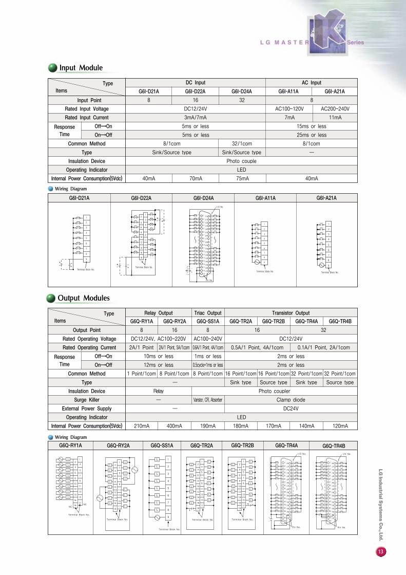
Input Module
Output Modules
L
L
L
L
L
L
L
L
NC
Terminal Block No.
Terminal Block No. Terminal Block No.
NC
12
34
56
7
98
1110
1213
1415
1617
18
LL
L
L
LL
LL
L
L
L
L
L
L
L
L
12
3
45
67
89
10
1213
14
1516
1718
L
L
L
L
L
L
L
L
LL
L
L
L
L
L
L
L
L
L
L
L
L
1
3
5
7
9
11
13
15
17
2
4
6
8
10
12
14
16
18
11
Terminal Block No.
LL
L
L
L
L
L
L
L
L
L
L
L
L
1
3
5
7
9
11
13
15
17
2
4
6
8
10
12
14
16
18
1
2
3
4
5
6
7
8
9
Terminal Block No.
0
2
4
6
8
A
C
E
0
2
4
6
8
A
C
E
1
3
5
7
9
B
D
F
1
3
5
7
9
B
D
F
1
3
5
7
9
B
D
F
1
3
5
7
9
B
D
F
L L
LL
Pin No. Pin No.
I/O No. I/O No.
8
DC12/24V
3mA/7mA
5ms or less
5ms or less
32/1com
Sink/Source type
8/1com
Sink/Source type
Photo couple
LED
40mA40mA 70mA 75mA
16 32 8
AC200~240V
11mA
15ms or less
25ms or less
8/1com
─
AC100~120V
7mA
TypeItems
Input Point
Rated Input Voltage
Rated Input Current
Off→On
On→Off
Common Method
Type
Insulation Device
Operating Indicator
Internal Power Consumption(5Vdc)
DC Input
G6I-D21A G6I-D22A G6I-D24A G6I-A11A G6I-A21A
AC Input
ResponseTime
8
DC12/24V, AC100~220V
2A/1 Point, 5A/1com2A/1 Point
10ms or less
12ms or less
8 Point/1com
2ms or less
2ms or less
Relay
1 Point/1com
Sink type Source type Sink type Source type─
Photo coupler
Clamp diode
DC24V
LED
120mA210mA 400mA 190mA 180mA 170mA 140mA
16 8
AC100~240V
0.6A/1 Point, 4A/1com
1ms or less
0.5cycle+1ms or less
8 Point/1com
Varistor, CR, Absorber
16 Point/1com 16 Point/1com 32 Point/1com 32 Point/1com
16
DC12/24V
0.1A/1 Point, 2A/1com0.5A/1 Point, 4A/1com
32
TypeItems
Output Point
Rated Operating Voltage
Rated Operating Current
Off→On
On→Off
Common Method
Type
Insulation Device
Surge Killer
External Power Supply
Operating Indicator
Internal Power Consumption(5Vdc)
Relay Output Triac Output
G6Q-RY1A G6Q-RY2A G6Q-SS1A G6Q-TR2A G6Q-TR2B G6Q-TR4A G6Q-TR4B
Transistor Output
ResponseTime
─
─
Terminal Block No. Terminal Block No.
1817
1615
1413
1211
109
87
65
43
21 0
2
4
6
8
A
C
E
0
2
4
6
8
A
C
E
1
3
5
7
9
B
D
F
1
3
5
7
9
B
D
F
I/O No.
Pin No.
Terminal Block No.
1
2
3
4
5
6
7
8
9
Terminal Block No.
1
2
3
4
5
6
7
8
9
G6I-D24AG6I-D21A G6I-D22A G6I-A11A G6I-A21A
G6Q-RY1A G6Q-RY2A G6Q-SS1A G6Q-TR2A G6Q-TR2B G6Q-TR4A G6Q-TR4B
Wiring Diagram
Wiring Diagram
14
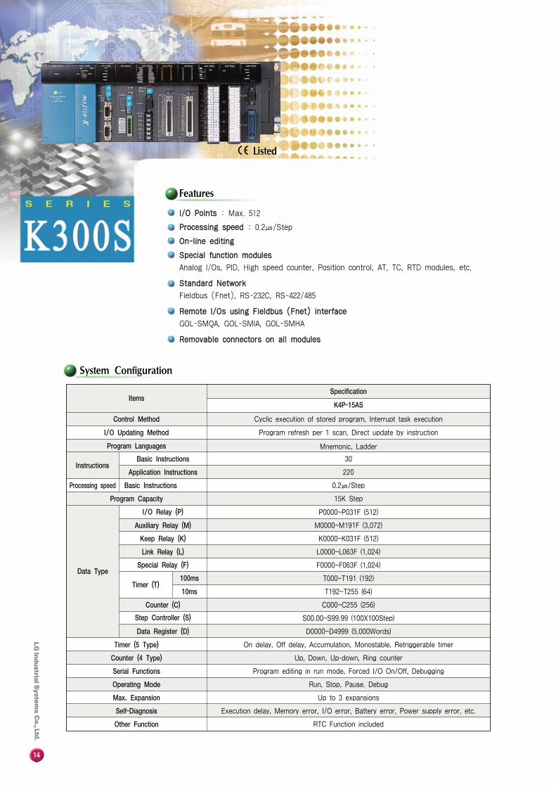
System Configuration
II//OO PPooiinnttss : Max. 512
PPrroocceessssiinngg ssppeeeedd : 0.2㎲/Step
OOnn--lliinnee eeddiittiinngg
SSppeecciiaall ffuunnccttiioonn mmoodduulleess
Analog I/Os, PID, High speed counter, Position control, AT, TC, RTD modules, etc.
SSttaannddaarrdd NNeettwwoorrkk
Fieldbus (Fnet), RS-232C, RS-422/485
RReemmoottee II//OOss uussiinngg FFiieellddbbuuss ((FFnneett)) iinntteerrffaaccee
GOL-SMQA, GOL-SMIA, GOL-SMHA
RReemmoovvaabbllee ccoonnnneeccttoorrss oonn aallll mmoodduulleess
ItemsSpecification
K4P-15AS
Control Method
Program Languages
I/O Updating Method
InstructionsBasic Instructions
Application Instructions
Basic Instructions
Program Capacity
Data Type
I/O Relay (P)
Auxiliary Relay (M)
Keep Relay (K)
Link Relay (L)
Special Relay (F)
Timer (T)100ms
10ms
Counter (C)
Step Controller (S)
Data Register (D)
Timer (5 Type)
Counter (4 Type)
Serial Functions
Operating Mode
Max. Expansion
Self-Diagnosis
Other Function
Cyclic execution of stored program, Interrupt task execution
Mnemonic, Ladder
Program refresh per 1 scan, Direct update by instruction
30
220
0.2㎲/Step
15K Step
M0000~M191F (3,072)
K0000~K031F (512)
L0000~L063F (1,024)
F0000~F063F (1,024)
T000~T191 (192)
T192~T255 (64)
C000~C255 (256)
S00.00~S99.99 (100X100Step)
D0000~D4999 (5,000Words)
On delay, Off delay, Accumulation, Monostable, Retriggerable timer
Up, Down, Up-down, Ring counter
Program editing in run mode, Forced I/O On/Off, Debugging
Run, Stop, Pause. Debug
Up to 3 expansions
Execution delay, Memory error, I/O error, Battery error, Power supply error, etc.
RTC Function included
P0000~P031F (512)
Processing speed
Features
Listed
15
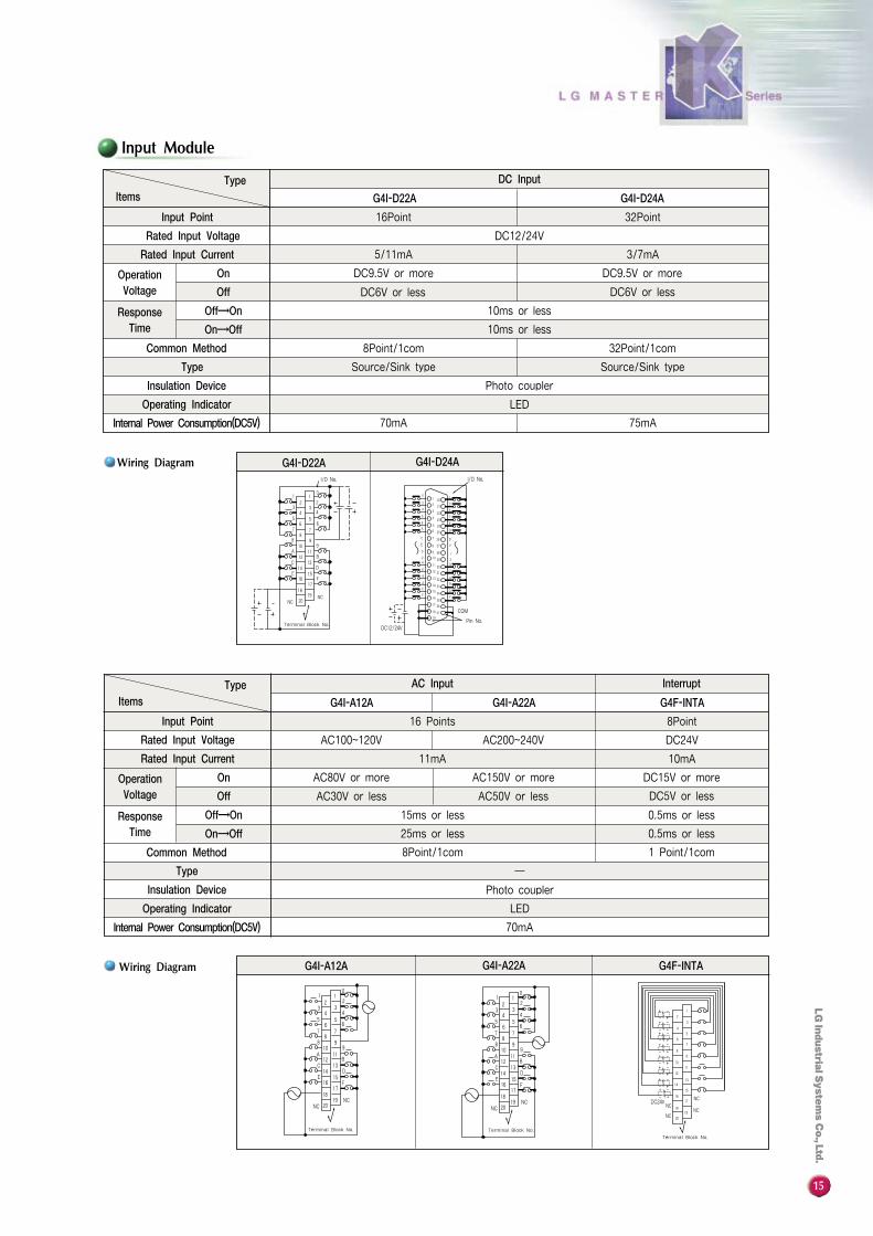
Input Module
Pin No.19
18 37
17 36
1635
3415
14 33
E
C
A
8
6
13
12
32
31
3011
7
9
B
D
F
52910
42
0 9 28
278
7 26C
E
D
F
1
3
6A
8
6
4
2
01
2
3
4
5
20
21
22
23
24
25
1
3
5
7
9
B
COM
DC12/24V
I/O No.
G4I-D22A G4I-D24A
16 Points
AC200~240VAC100~120V
11mA
AC150V or more
AC50V or lessAC30V or less
15ms or less
25ms or less
8Point/1com
─
AC80V or more
8Point
DC24V
10mA
DC15V or more
DC5V or less
0.5ms or less
0.5ms or less
1 Point/1com
Photo coupler
LED
70mA
TypeItems
Input Point
Rated Input Voltage
Rated Input Current
On
Off
Off→On
On→Off
Common Method
Type
Insulation Device
Operating Indicator
Internal Power Consumption(DC5V)
AC Input Interrupt
G4I-A12A G4I-A22A G4F-INTA
OperationVoltage
ResponseTime
16Point
DC12/24V
3/7mA
DC9.5V or more
DC6V or less
5/11mA
DC9.5V or more
DC6V or less
10ms or less
10ms or less
8Point/1com 32Point/1com
Source/Sink type Source/Sink type
Photo coupler
LED
70mA 75mA
32Point
TypeItems
Input Point
Rated Input Voltage
Rated Input Current
On
Off
Off→On
On→Off
Common Method
Type
Insulation Device
Operating Indicator
Internal Power Consumption(DC5V)
DC Input
G4I-D22A G4I-D24A
OperationVoltage
ResponseTime
Wiring Diagram
Wiring Diagram G4I-A12A G4I-A22A G4F-INTA
01 1
2 23 3
4 455
6 677
88 9
91011
1213
1415
1617
1819
20
AB
CD
EF
NCNC
Terminal Block No.
I/O No.
1 10
2233
4 455
6 677
88 9
91011
12 BA
1314 D
F
C
E 1516
1718
1920
NCNC
Terminal Block No. Terminal Block No.
Terminal Block No.
1 10
2233
4 455
6 677
88 9
91011
12 BA
1314 D
F
C
E 1516
1718
1920
NCNC
NC
NC
NCNC
1
2
3
4
5
67
89
1011
12
1314
15
1617
1819
20
DC24V

16
Output Module
16 Points
DC12/24V
0.1A/1 Point, 2A/1com
2ms or less
2ms or less
8 Poinst/1com 8 Points/1com 32 Points/1com 32 Points/1com
Sink type
Photo coupler
─Varistor
DC24V
LED
100mA 100mA 160mA 160mA
Source type Sink type Source type
0.5A/1 Point, 3A/1com
32 Points
TypeItems
Input Point
Rated Input Voltage
Rated Input Current
Off→On
On→Off
Common Method
Type
Insulation Device
Surge Killer
External Power Supply
Operation Indicator
Internal Power Consumption(DC5V)
Transistor Output
G4Q-TR2A G4Q-TR2B G4Q-TR4A G4Q-TR4B
ResponseTime
Photo coupler
DC24V ─
LED
100mA
16Point
AC100~240V
0.6A/1 Point, 2.4A/1com1A/1 Point, 5A/1com
0.5cycle+1ms or less
0.5cycle+1ms or less
Varistor, CR Absorber
DC24V, AC100~220V
1A/1 Point, 4A/1com
10ms or less
12ms or less
8Point/1com
─
─
330mA
TypeItems
Output Point
Rated Input Voltage
Rated Input Current
Off→On
On→Off
Common Method
Type
Insulation Device
Surge Killer
External Power Supply
Operation Indicator
Internal Power Consumption(DC5V)
Relay Output Triac Output
G4Q-RY2A G4Q-SS2A G4Q-SS2B
ResponseTime
Wiring Diagram
Wiring Diagram
Terminal Block No. Terminal Block No.
2019
1817
EF
C
AD
B
1615
1314
12118
109
9
877
56
56
43
4
23
21 1
0
2019
1817
EF
C
AD
B
1615
1314
12118
109
9
877
56
56
43
4
23
21 1
0 0
2
4
6
8
A
1 20
2 21
3 22
4 23
5 24
6 25
1
3
5
7
9
B
7 26
8 27
9 28
10 29
11 30
12
13
14
15
31
32
33
34
C
E
D
F0
24
1
3
5
6 7
8 9
A
C
E
B
D
F16 35
17
18
19
36
37
Pin No.Pin No.
I/O No.I/O No.I/O No.
0
2
4
6
8
A
1 20
2 21
3 22
4 23
5 24
6 25
1
3
5
7
9
B
7 26
8 27
9 28
10 29
11 30
12
13
14
15
31
32
33
34
C
E
D
F0
24
1
3
5
6 7
8 9
A
C
E
B
D
F16 35
17
18
19
36
37
I/O No.
L
L
L
L
L
L
L
L
L
L
L
L
L
L
L
L
L
L
L
L
L
L
L
L
L
L
L
L
L
L
L
L
LLLLLL
L
L
L
L
LLLLLL
LLLLLL
LLLLLL
LLLLLL
LLLLLL
LLLLLL
LLLLLL
G4Q-TR4BG4Q-TR4AG4Q-TR2BG4Q-TR2A
G4Q-RY2A G4Q-SS2A G4Q-SS2B
12
12
0
3
54
3
54
67 7
8
6
8 9910
11A12 B
C 13D
E14
1615
1817
2019
F
Terminal Block No.
Terminal Block No.
Terminal Block No.
2019
1817
1615
1413
12
EF
CD
A 1110
99
B
88
776
45
65
433
21 1
0
2
2019
1817
1615
1413
12
EF
CD
A 1110
99
B
88
776
45
65
433
21 1
0
2
L
L
L
L
L
L
L
L
L
L
L
L
L
L
L
L
L
L
L
L
L
L
L
L
L
L
L
L
L
L
L
L
L
L
L
L
L
L
L
L
L
L
L
L
L
L
L
L
17
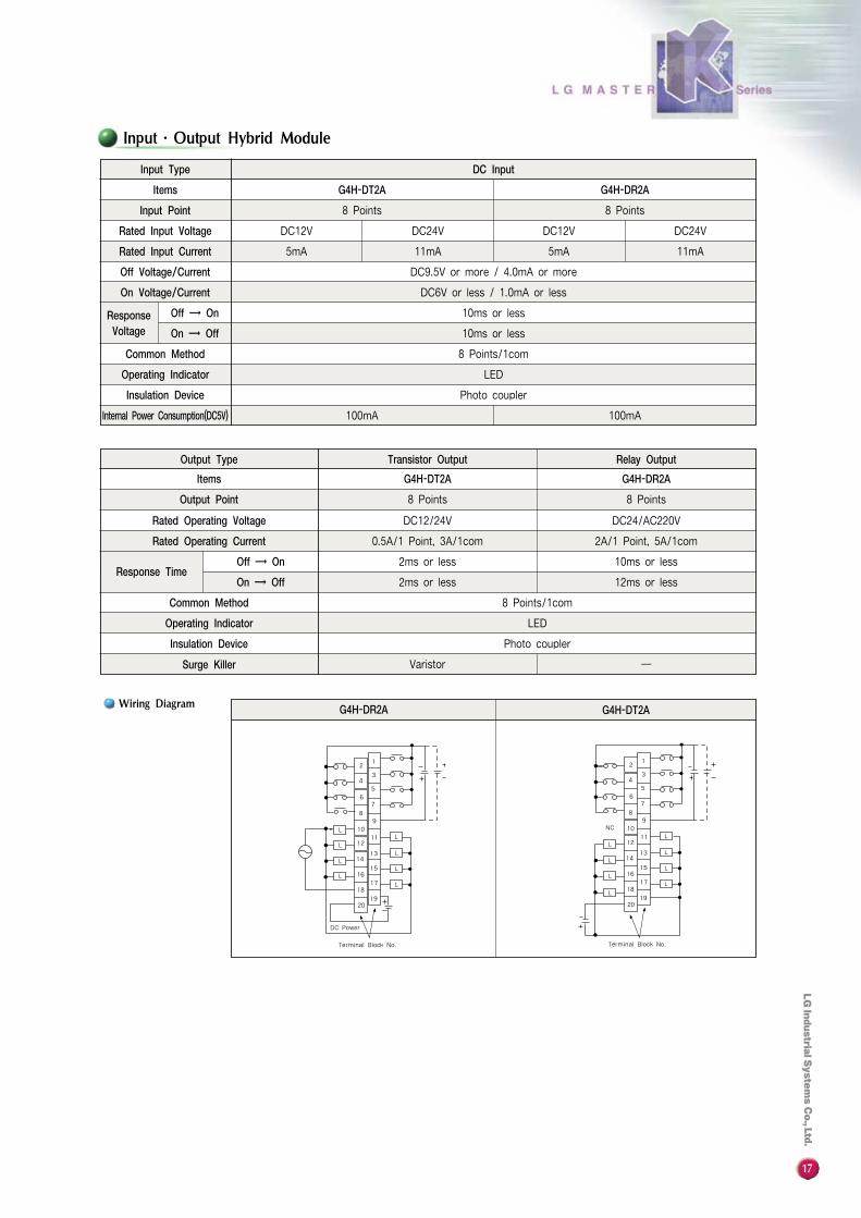
Input∙Output Hybrid Module
G4H-DT2A G4H-DR2A
8 Points
DC24V
8 Points
DC12VDC12V DC24V
11mA 5mA5mA 11mA
DC9.5V or more / 4.0mA or more
DC6V or less / 1.0mA or less
10ms or less
10ms or less
8 Points/1com
LED
Photo coupler
100mA100mA
Input Type
Items
Input Point
Rated Input Voltage
Rated Input Current
Off Voltage/Current
On Voltage/Current
Off → On
On → Off
ResponseVoltage
Common Method
Operating Indicator
Insulation Device
Internal Power Consumption(DC5V)
DC Input
G4H-DT2A G4H-DR2A
8 Points 8 Points
DC12/24V DC24/AC220V
0.5A/1 Point, 3A/1com 2A/1 Point, 5A/1com
2ms or less 10ms or less
2ms or less 12ms or less
8 Points/1com
LED
Photo coupler
Varistor ─
Output Type
Items
Output Point
Rated Operating Voltage
Rated Operating Current
Off → On
On → OffResponse Time
Common Method
Operating Indicator
Insulation Device
Surge Killer
Transistor Output Relay Output
1
34
5
2
67
89
10
1112
1314
1516
1718
1920
L
L
L
LL
L
L
L
DC Power
Terminal Block No.
1
34
5
2
67
89
10
1112
1314
1516
1718
1920
L
L
LL
L
L
L
NC
Terminal Block No.
L
G4H-DR2A G4H-DT2AWiring Diagram
18
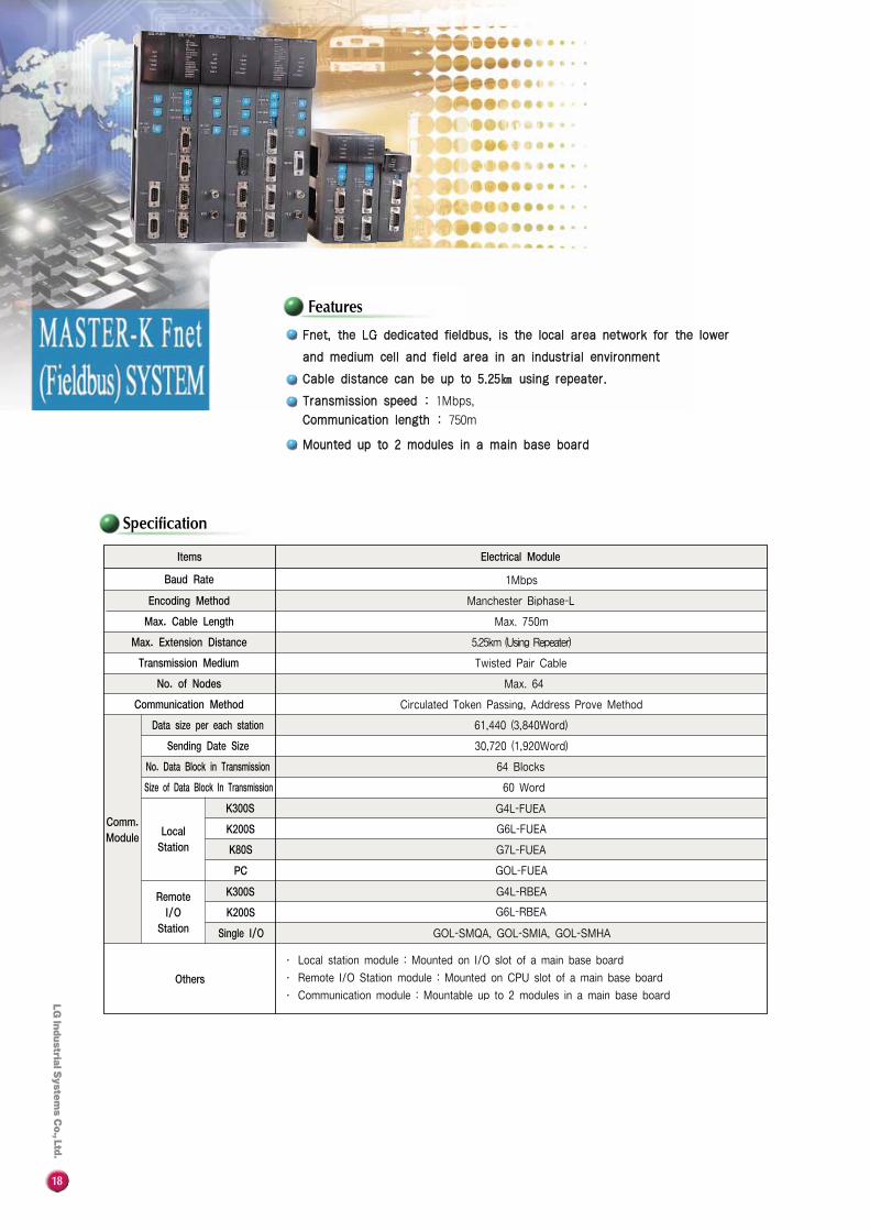
Specification
FFnneett,, tthhee LLGG ddeeddiiccaatteedd ffiieellddbbuuss,, iiss tthhee llooccaall aarreeaa nneettwwoorrkk ffoorr tthhee lloowweerr
aanndd mmeeddiiuumm cceellll aanndd ffiieelldd aarreeaa iinn aann iinndduussttrriiaall eennvviirroonnmmeenntt
CCaabbllee ddiissttaannccee ccaann bbee uupp ttoo 55..2255㎞㎞ uussiinngg rreeppeeaatteerr..
TTrraannssmmiissssiioonn ssppeeeedd :: 1Mbps,
CCoommmmuunniiccaattiioonn lleennggtthh :: 750m
MMoouunntteedd uupp ttoo 22 mmoodduulleess iinn aa mmaaiinn bbaassee bbooaarrdd
Items Electrical Module
Baud Rate
Encoding Method
Max. Cable Length
Max. Extension Distance
Transmission Medium
No. of Nodes
Communication Method
Comm.Module
Others
Data size per each station
Sending Date Size
No. Data Block in Transmission
Size of Data Block In Transmission
Local Station
Remote I/O
Station
K300S
K200S
PC
K300S
K200S
Single I/O
1Mbps
Manchester Biphase-L
Max. 750m
5.25km (Using Repeater)
Twisted Pair Cable
Max. 64
Circulated Token Passing, Address Prove Method
61,440 (3,840Word)
30,720 (1,920Word)
64 Blocks
60 Word
G4L-FUEA
G6L-FUEA
GOL-FUEA
G6L-RBEA
K80S G7L-FUEA
G4L-RBEA
GOL-SMQA, GOL-SMIA, GOL-SMHA
∙ Local station module : Mounted on I/O slot of a main base board
∙ Remote I/O Station module : Mounted on CPU slot of a main base board
∙ Communication module : Mountable up to 2 modules in a main base board
Features
19
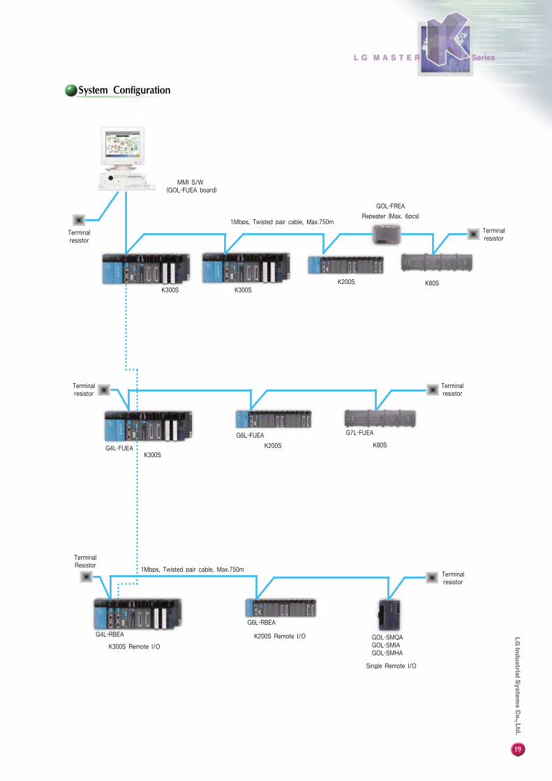
System Configuration
MMI S/W(GOL-FUEA board)
1Mbps, Twisted pair cable, Max.750m
Terminalresistor
Terminalresistor
Terminalresistor
Terminalresistor
1Mbps, Twisted pair cable, Max.750m
K300S K300SK80SK200S
Repeater (Max. 6pcs)
GOL-FREA
G4L-FUEA
G4L-RBEA
G6L-RBEA
G6L-FUEA G7L-FUEA
Terminalresistor
TerminalResistor
K300S
K300S Remote I/O
K200S
K200S Remote I/O
K80S
GOL-SMQAGOL-SMIAGOL-SMHA
Single Remote I/O
20
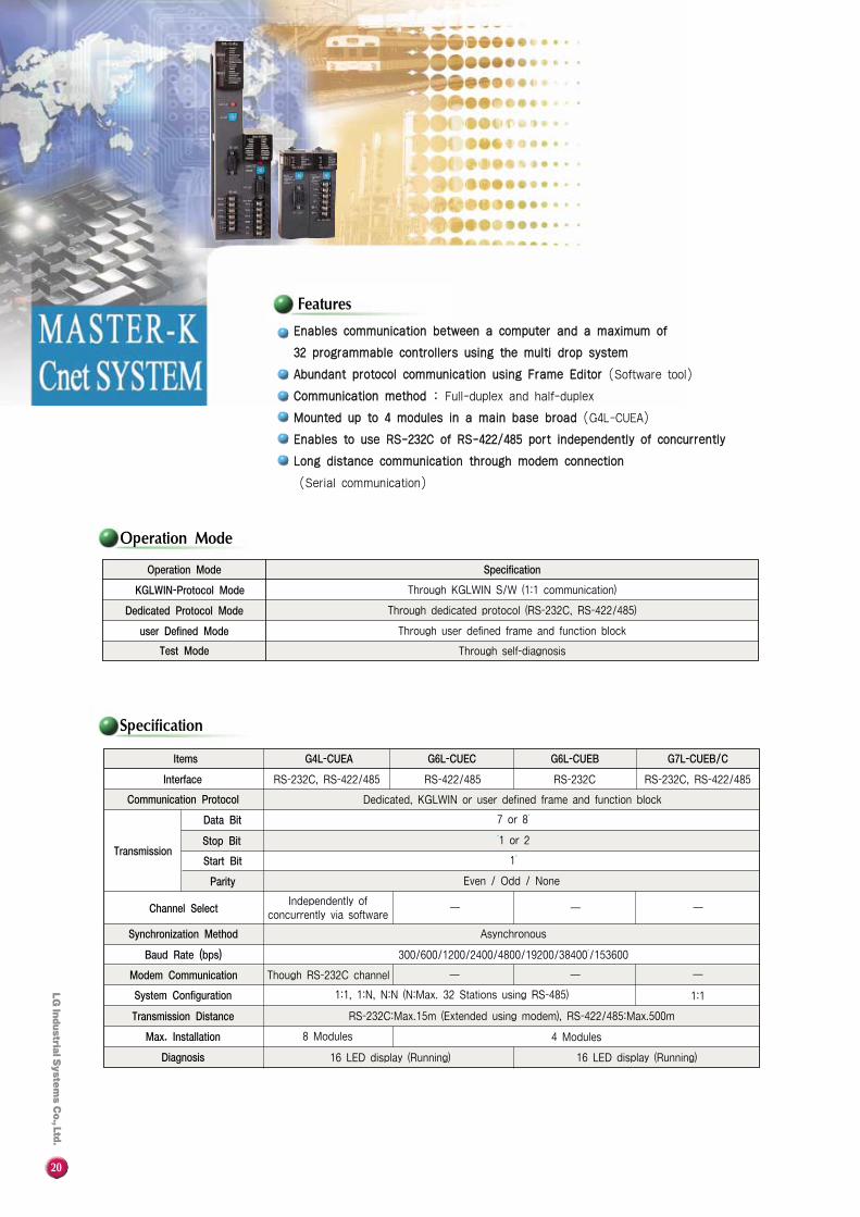
Operation Mode
Specification
Items G4L-CUEA G6L-CUEC G6L-CUEB G7L-CUEB/C
Operation Mode
KGLWIN-Protocol Mode
Dedicated Protocol Mode
user Defined Mode
Test Mode
Specification
Interface
Communication Protocol
Data Bit
Stop Bit
Start Bit
Parity
Transmission
Channel Select
Synchronization Method
Baud Rate (bps)
Modem Communication
System Configuration
Transmission Distance
Max. Installation
Diagnosis
RS-232C, RS-422/485 RS-422/485
Dedicated, KGLWIN or user defined frame and function block
RS-232C
7 or 8*
*1 or 2
1*
Even / Odd / None
───Independently of
concurrently via software
Asynchronous
300/600/1200/2400/4800/19200/38400*/153600
───
1:1
Though RS-232C channel
1:1, 1:N, N:N (N:Max. 32 Stations using RS-485)
RS-232C:Max.15m (Extended using modem), RS-422/485:Max.500m
4 Modules
16 LED display (Running)
Through KGLWIN S/W (1:1 communication)
Through dedicated protocol (RS-232C, RS-422/485)
Through user defined frame and function block
Through self-diagnosis
8 Modules
16 LED display (Running)
RS-232C, RS-422/485
Features
EEnnaabblleess ccoommmmuunniiccaattiioonn bbeettwweeeenn aa ccoommppuutteerr aanndd aa mmaaxxiimmuumm ooff
3322 pprrooggrraammmmaabbllee ccoonnttrroolllleerrss uussiinngg tthhee mmuullttii ddrroopp ssyysstteemm
AAbbuunnddaanntt pprroottooccooll ccoommmmuunniiccaattiioonn uussiinngg FFrraammee EEddiittoorr (Software tool)
CCoommmmuunniiccaattiioonn mmeetthhoodd :: Full-duplex and half-duplex
MMoouunntteedd uupp ttoo 44 mmoodduulleess iinn aa mmaaiinn bbaassee bbrrooaadd (G4L-CUEA)
EEnnaabblleess ttoo uussee RRSS--223322CC ooff RRSS--442222//448855 ppoorrtt iinnddeeppeennddeennttllyy ooff ccoonnccuurrrreennttllyy
LLoonngg ddiissttaannccee ccoommmmuunniiccaattiioonn tthhrroouugghh mmooddeemm ccoonnnneeccttiioonn
(Serial communication)
21
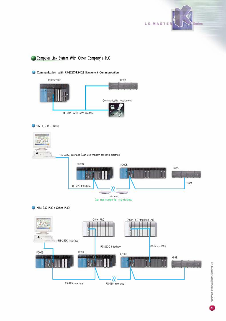
Computer Link System With Other Company’s PLC
RS-232C or RS-422 Interface
K200S
Cnet
K300S
RS-232C Interface (Can use modem for long distance)
RS-422 Interface
(Mobdus, DF1)
Other PLC (Mobdus, AB)Other PLC
RS-485 Interface
RS-232C Interface
Communication With RS-232C/RS-422 Equipment Communication
1:N (LG PLC Link)
N:M (LG PLC+Other PLC)
RS-232C Interface
K300SK300SK200S
Communication equipment
��
RS-485 Interface
��
Modem
Can use modem for long distance
K80SK300S/200S
K80S
K80S

22
System Configuration
Feature of I/O Conversion
Specification
Features
[ ]1/16,000
Example
�
�
�
�
�
�
�
�
-10V
0V
-20mA
4mA
─
─
─
─
0V
5V
0mA
12mA
─
─
─
─
-10~+10V
0~+10V
-20~+20mA
+4~20mA
+1~+5V
0~+10V
-10~+10V
+4~20mA
Offset Gain Input Range
44//88 cchhaannnneellss ppeerr mmoodduullee
SSeelleeccttaabbllee ddiiggiittaall ccoonnvveerrtteedd rraannggee ppeerr cchhaannnneell (G4F-AD2A)
SSeelleeccttaabbllee vvoollttaaggee//CCuurrrreenntt ttyyppee bbyy ddiipp sswwiittcchheerr tteerrmmiinnaall
CCoonnvveerrttss rraattiioonnss vvaarriioouuss bbyy sseettttiinngg ooffffsseett aanndd ggaaiinn vvaalluueess (G4F-AD2A)
HHiigghh rreessoolluuttiioonn (1/16,000) (G4F-AD2A)
ItemsSpecification
K300S
8
DC 1~5V, DC 0~10V
* DC 4~20mA
Setting by dip switch
0~4,000
─
1mV
2.5mV
─
4㎂
─
5ms/1channel
500mA
Sampling, Average
Impossible
16 Points
G4F-AD3A G4F-AD2A G6F-AD2A
Type
Input Channel
AnalogInputRange
Voltage
Current
Voltage/Current Select
Digital Converted Range
DC -5~+5V
DC 1~+5V
DC 0~+10V
DC -10~+10V
DC 4~20mA
DC -20~+20mA
Over Accuracy
Response Time
Voltage
Current
Insulation
Internal Current consumption
Processing
Setting OffSet/Gain
Possession Points
Absolute InputRange
Max.Re-solution
K200S
44
DC -5~5, * DC -10~10V DC 1~5V, 0~10V, * DC -10~10V
* DC -20~20mA * DC 4~20mA
Setting by terminal block
-8,000~+8,000/0~16,000 (selectable per channel) 0~4000, -2000~2000
0.625mV ─
─ 1mV
─ 2.5mV
1.25mV 5mV
─ 4㎂
2.5㎂ ─
±0.5% (Full scale)
3ms/1channel 5ms/1channel
±12V
±25mA
Photo coupler insulated input terminal and power supply (Net isolated between channel)
400mA 400mA
Sampling, AverageFilter, Sampling, Average
Possible Impossible
� K200S Analog input module use GM6-PAFB (Power supply) Only � *Default setting value
4mA 20mA
4,000
Analog Voltage Input[mA]
Digital Output
⑧
-10V 0 1V 5V 10V
4,000
2,000
Analog Voltage Input[V]
Digital Output
⑥
⑤
⑦
K300SG4F-AD3A
CH0
CH1
Analog Voltage Input (0~10V)
(4~20mA)
VI
(GET)
(PUT)
Data Input (Channel Data Type)
Converted Data read
Traducer
Pre-Amp
Voltage, Current, Power
Temperature, Flay, Pressure, SpeedVI
COM
Analog Current Input[mA]
-20mA -10mA 4mA 10mA 20mA
16,000
8,000
Digital Output
③③
④
-10V -5V 0 5V 10V
16,000
8,000
Analog Voltage Input[V]
Digital Output
[ ]1/4000 [ ]1/4000①
②
COM

23
System Configuration
Features
Specification
Feature of I/O Conversion
Example
�
�
�
�
�
�
�
�
-10V
-5V
1V
─
─
4mA
8mA
─
0V
0V
3V
─
─
12mA
12mA
─
-10~+10V
-5~+5V
+1~+5V
-10~+10V
-5~+5V
4~20mA
8~16mA
4~20mA
Offset Gain Input Range
� *Default setting value
ItemsSpecification
K300S K200S
2 8 4 8 4 4
-8000~8000, 0~16000 0~4000
DC -10~10V
DC 4~20mADC -10~10V DC 4~20mA DC -10~10V DC 4~20mA
1.25mV/1㎂ 5mV 4㎂ 5mV 4㎂
±0.3% (Full scale) ±0.5% (Full scale)
3ms/2Ch 15ms/8Ch 10ms/4Ch 15ms/8Ch 10ms/4Ch
DC ±15V
DC +24mADC ±15V DC +24mA DC ±15V DC +24mA
─ ─DC 24V
450mA 700mA 400mA 60mA 680mA 40mA
80mA
60mA 25mA
120mA─
─
Possible ─
16 Points
Photo coupler (between channels : not isolated)
G4F-DA1A G4F-DA3V G4F-DA2V G4F-DA3I G4F-DA2I G6F-DA2V G6F-DA2I
Type
Output Channel
Input Range
Output
Max. Resolution
Overall Accuracy
Response Time
Absolute Input Range
Isolation Method
External Power
Current Consumption (5V)(+15V)(-15V)
Setting Offset/Gain
Possession Points
� K200S Analog Mode Must Use GM6-PAFB Features of I/O Conversion
[ ] [ ] [ ] [ ]
Current Output Features (mA)
④
⑤
Voltage Output Features (V)
①
②
③
⑥
⑦⑧
OutputOutput
Digital Input
Gain
Offset
0 8,000 16,000 0 2,000 4,000
20mA
16mA
12mA
8mA
4mA
20mA
12mA
4mA
AnalogOutput Range
11//1166,,000000
Digital InputGain
Offset
0 8,000 16,000 0 2,000 4,000
10V
5V
3V1V
-5V
-10V
10V
5V
-5V
-10V
AnalogOutput Range
11//44,,000000 11//1166,,000000 11//44,,000000
K300S G4F-DA3V
+15V -15V0V
Analog Voltage Input(0~10V)
External Power
(PUT)
(PUT)
Data Input
Countered Data Write
Variable speed drive
Controllers
Servo controller
Voltage, Current, PowerM
M Servo motor tongue
Temperature, Flay, Pressure, Speed
22//44//88 cchhaannnneellss ppeerr mmoodduullee
VVaarriioouuss aannaalloogg oouuttppuutt ttyyppee (Voltage/Current, Voltage, Current)CCuurrrreenntt : G4F-DA3I, G4F-DA2I, G6F-DA2IVVoollttaaggee : G4F-DA3V, G4F-DA2V, G6F-DA2V VVoollttaaggee,, CCuurrrreenntt : G4F-DA1A
SSeett ttaabbllee aannaalloogg oouuttppuutt ssttaattee(While CPU stop, Middle Values, Previous Value, Max. Value,Min. Values)
24
Specification
Features of I/O Conversion Configuration
Features
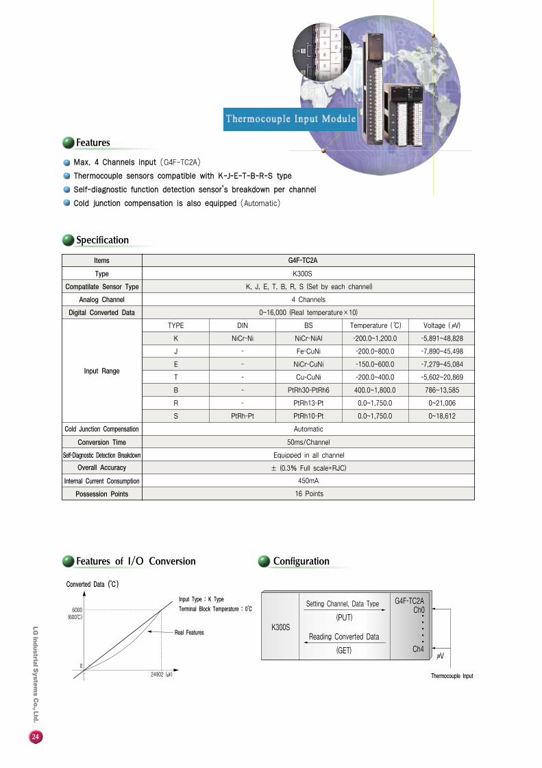
MMaaxx.. 44 CChhaannnneellss iinnppuutt (G4F-TC2A)
TThheerrmmooccoouuppllee sseennssoorrss ccoommppaattiibbllee wwiitthh KK--JJ--EE--TT--BB--RR--SS ttyyppee
SSeellff--ddiiaaggnnoossttiicc ffuunnccttiioonn ddeetteeccttiioonn sseennssoorr’’ss bbrreeaakkddoowwnn ppeerr cchhaannnneell
CCoolldd jjuunnccttiioonn ccoommppeennssaattiioonn iiss aallssoo eeqquuiippppeedd (Automatic)
Items
K300S
K, J, E, T, B, R, S (Set by each channel)
4 Channels
0~16,000 (Real temperature×10)
BS Temperature ( ℃) Voltage ( μV)
NiCr-NiAl -200.0~1,200.0 -5,891~48,828
Fe-CuNi -200.0~800.0 -7,890~45,498
NiCr-CuNi -150.0~600.0 -7,279~45,084
Cu-CuNi -200.0~400.0 -5,602~20,869
PtRh30-PtRh6 400.0~1,800.0 786~13,585
PtRh13-Pt 0.0~1,750.0 0~21,006
PtRh10-Pt
TYPE
K
J
E
T
B
R
S
DIN
NiCr-Ni
-
-
-
-
-
PtRh-Pt 0.0~1,750.0 0~18,612
Automatic
50ms/Channel
Equipped in all channel
± (0.3% Full scale+RJC)
450mA
16 Points
G4F-TC2A
Type
Compatilate Sensor Type
Analog Channel
Digital Converted Data
Input Range
Cold Junction Compensation
Conversion Time
Self-Diagnostic Detection Breakdown
Overall Accuracy
Internal Current Consumption
Possession Points
24902 (㎶)
6000(600℃)
0
Converted Data (℃)
Real Features
Input Type : K Type
Terminal Block Temperature : 0℃
(GET)
(PUT)
Setting Channel, Data Type
Reading Converted DataK300S
G4F-TC2ACh0
Ch4μV
Thermocouple Input
∙∙∙∙∙
25
Features
Specification
System ConfigurationFeatures of I/O Conversion
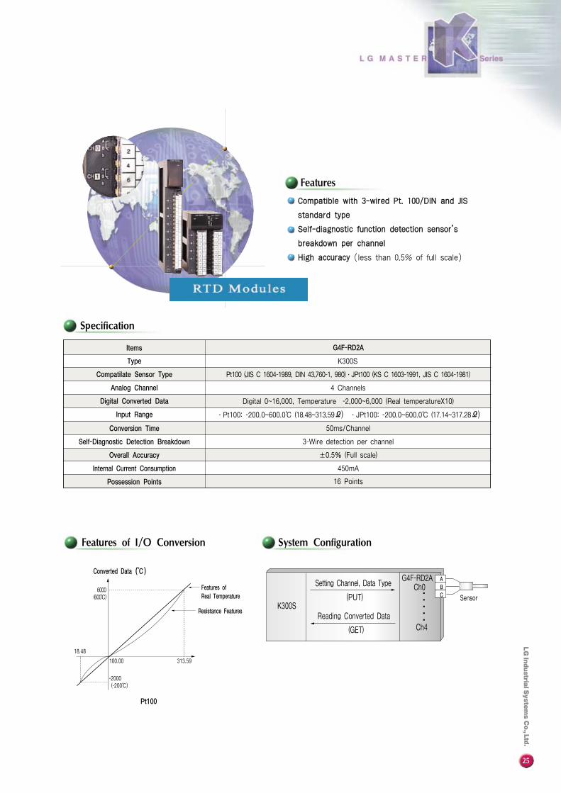
CCoommppaattiibbllee wwiitthh 33--wwiirreedd PPtt.. 110000//DDIINN aanndd JJIISS
ssttaannddaarrdd ttyyppee
SSeellff--ddiiaaggnnoossttiicc ffuunnccttiioonn ddeetteeccttiioonn sseennssoorr’’ss
bbrreeaakkddoowwnn ppeerr cchhaannnneell
HHiigghh aaccccuurraaccyy (less than 0.5% of full scale)
Items
Pt100 (JIS C 1604-1989, DIN 43,760-1, 980)∙JPt100 (KS C 1603-1991, JIS C 1604-1981)
4 Channels
Digital 0~16,000, Temperature -2,000~6,000 (Real temperatureX10)
∙Pt100: -200.0~600.0℃ (18.48~313.59Ω) ∙JPt100: -200.0~600.0℃ (17.14~317.28Ω)
50ms/Channel
3-Wire detection per channel
±0.5% (Full scale)
450mA
16 Points
K300S
G4F-RD2A
Type
Compatilate Sensor Type
Analog Channel
Digital Converted Data
Input Range
Conversion Time
Self-Diagnostic Detection Breakdown
Overall Accuracy
Internal Current Consumption
Possession Points
100.00 313.59
Converted Data (℃)
Resistance Features
Features of Real Temperature
6000(600℃)
Pt100
-2000(-200℃)
∙∙∙∙∙
(GET)
(PUT)
Reading Converted Data
Sensor
Setting Channel, Data Type
K300S
G4F-RD2ACh0
Ch4
ABC
18.48
26
Configuration
Features of I/O ConversionSpecification
Features
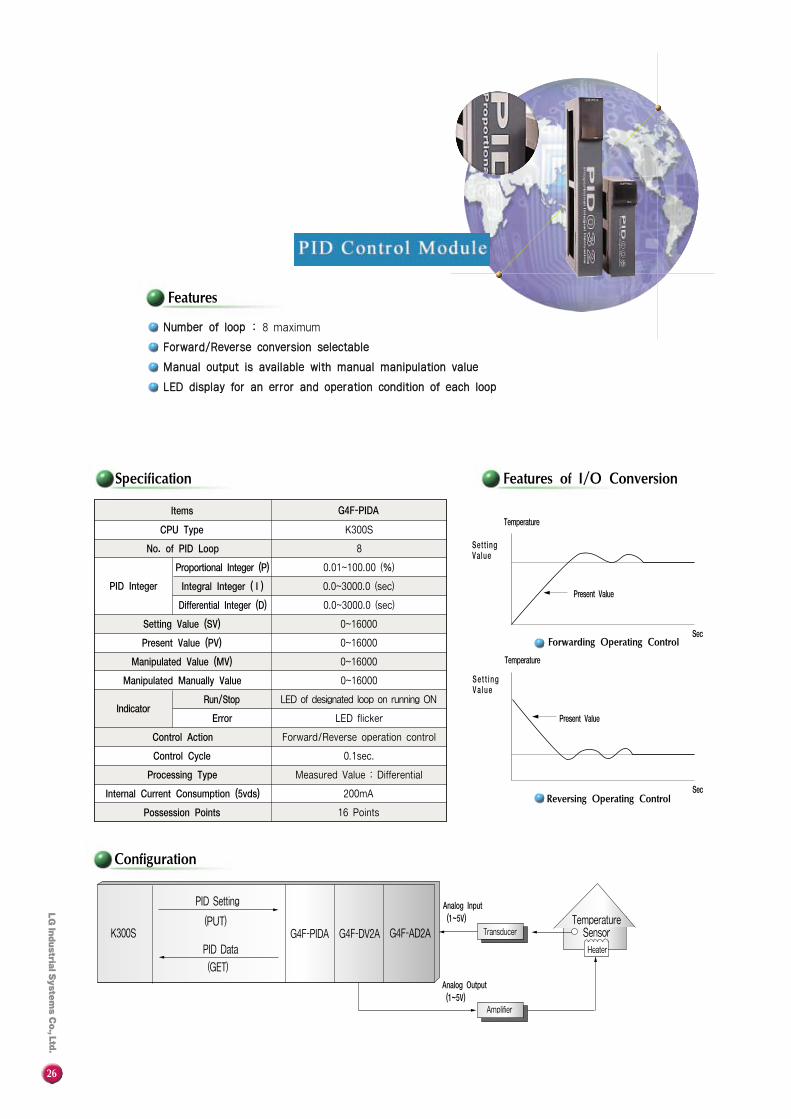
NNuummbbeerr ooff lloooopp :: 8 maximum
FFoorrwwaarrdd//RReevveerrssee ccoonnvveerrssiioonn sseelleeccttaabbllee
MMaannuuaall oouuttppuutt iiss aavvaaiillaabbllee wwiitthh mmaannuuaall mmaanniippuullaattiioonn vvaalluuee
LLEEDD ddiissppllaayy ffoorr aann eerrrroorr aanndd ooppeerraattiioonn ccoonnddiittiioonn ooff eeaacchh lloooopp
Items
CPU Type
No. of PID Loop
Proportional Integer (P)
Integral Integer ( I )
Differential Integer (D)
Setting Value (SV)
Present Value (PV)
Manipulated Value (MV)
Manipulated Manually Value
Run/Stop
Error
Control Action
Control Cycle
Processing Type
Internal Current Consumption (5vds)
Possession Points
Indicator
PID Integer
G4F-PIDA
K300S
8
0.01~100.00 (%)
0.0~3000.0 (sec)
0.0~3000.0 (sec)
0~16000
0~16000
0~16000
0~16000
LED of designated loop on running ON
LED flicker
Forward/Reverse operation control
0.1sec.
Measured Value : Differential
200mA
16 Points
Sec
Sec
Temperature
Temperature
Present Value
Present Value
Sett ingValue
Se t t i ngVa lue
Forwarding Operating Control
Reversing Operating Control
(GET)
(PUT)K300S G4F-PIDA G4F-DV2A G4F-AD2A
PID Setting
PID Data
Analog Input(1~5V) Temperature
Sensor
Heater
Transducer
Amplifier
Analog Output(1~5V)
27
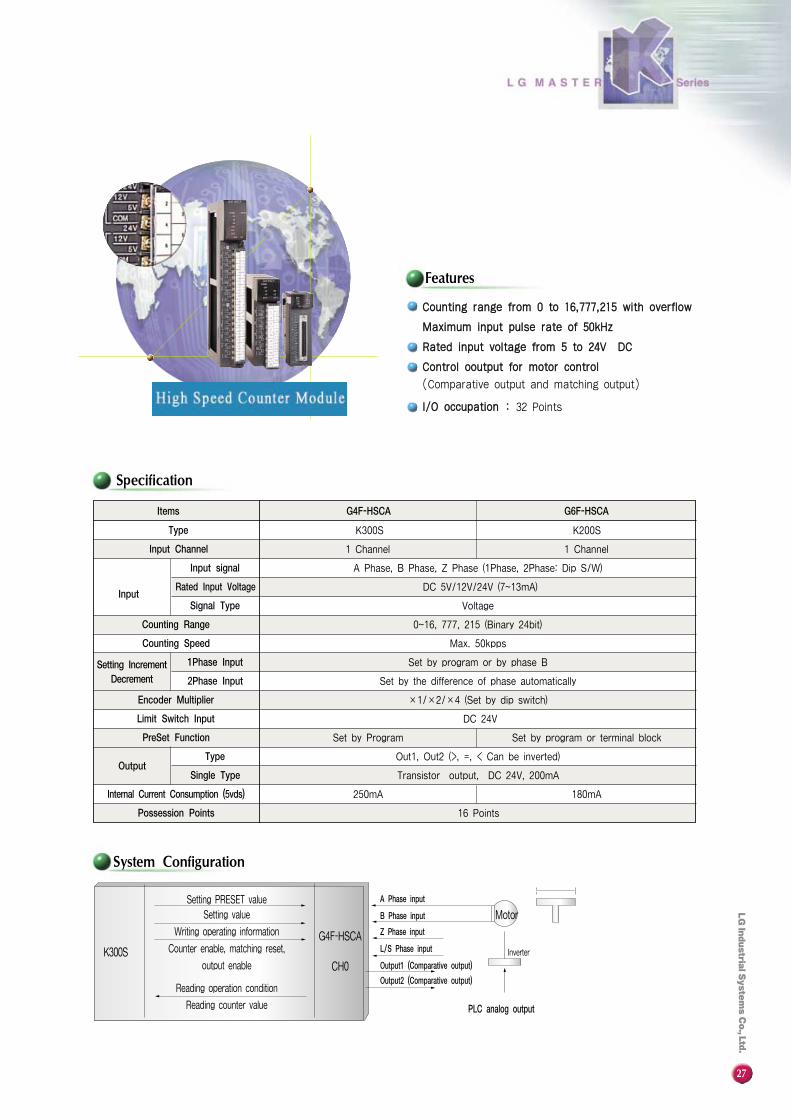
Features
System Configuration
Specification
Items
Type
Input Channel
Input
Input signal
Rated Input Voltage
Signal Type
Counting Range
Counting Speed
Setting IncrementDecrement
1Phase Input
2Phase Input
Encoder Multiplier
Limit Switch Input
PreSet Function
OutputType
Single Type
Internal Current Consumption (5vds)
Possession Points
G4F-HSCA G6F-HSCA
K300S K200S
1 Channel
A Phase, B Phase, Z Phase (1Phase, 2Phase: Dip S/W)
DC 5V/12V/24V (7~13mA)
Voltage
0~16, 777, 215 (Binary 24bit)
Max. 50kpps
Set by program or by phase B
Set by the difference of phase automatically
×1/×2/×4 (Set by dip switch)
Set by program or terminal block
DC 24V
Set by Program
Out1, Out2 (>, =, < Can be inverted)
Transistor output, DC 24V, 200mA
180mA
16 Points
250mA
1 Channel
CCoouunnttiinngg rraannggee ffrroomm 00 ttoo 1166,,777777,,221155 wwiitthh oovveerrffllooww
MMaaxxiimmuumm iinnppuutt ppuullssee rraattee ooff 5500kkHHzz
RRaatteedd iinnppuutt vvoollttaaggee ffrroomm 55 ttoo 2244VV DDCC
CCoonnttrrooll oooouuttppuutt ffoorr mmoottoorr ccoonnttrrooll
(Comparative output and matching output)
II//OO ooccccuuppaattiioonn :: 32 Points
Setting PRESET value
Setting value
Writing operating information
Counter enable, matching reset,
output enable
Reading operation condition
Reading counter value
A Phase input
B Phase input
Z Phase input
L/S Phase input
Output1 (Comparative output)
Output2 (Comparative output)
Motor
Inverter
PLC analog output
G4F-HSCA
CH0K300S

28
Wiring Diagrams
System Configuration
HHiigghh ssppeeeedd aanndd hhiigghhllyy pprreecciissee ppoossiittiioonniinngg
aatt aa mmaaxxiimmuumm 220000 kkppppss (Max. 16,744,447 pulse)
PPaarraammeetteerr && ppoossiittiioonniinngg ddaattaa sseettttiinngg ffrroomm
tthhee ssooffttwwaarree ppaacckkaaggee
EEaassyy ttoo uussee tthhee tteeaacchhiinngg uunniitt
VVaarriioouuss ppoossiittiioonniinngg ddrriivvee ppaatttteerrnnss
II//OO ooccccuuppaattiioonn :: 32 Points
Y축
X축K300S
K200S
G4F-P0PB
G6F-POPA
PUT/GET
Pulse OutputPG SM
PG SM
SM: Servo MotorPG: Encoder
Manual Pulsegeneration (MPG)
KGLWINPositioning
S/W
(Pos Pack)
(Sequence Programming) Position Programming Teaching Terminal (GOF-PTUA)
ServoDriver
Y-axis
X-axis
ServoDriver
CW
CCW
5/24 COM5/24 COM
5V5/24 GND
ZLZCOM
ORG+OV-OVEMG
ICOM
MPGBCOMMPGBCOM
26
4
131424123
286
31102032
1133
302987
+5VGND
MPG
+24VGND
5V
+5VCW+5VCCW
+5V
SV-ON
LEAD
LAG
Z
+5V
40393837
26
25
1413121110987
K300S TBL-i K300S
MPG
CWLG
CCWLG
Z
185164
150
MELSERVO-SA
Features
TTAAMMAAGGAAWWAA TTBBLL--ii TTyyppee ((XX--aaxxiiss)) MMIITTSSUUBBIISSHH MMEELLSSEERRVVOO--SSAA TTyyppee ((XX--aaxxiiss))
CW
CCW
5/24 COM5/24 COM
5V5/24 GND
ZLZCOM
ORG+OV-OVEMG
ICOM
MPGBCOMMPGBCOM
26
4
131424123
286
31102032
1133
302987
+5VGND
+24VGND
29
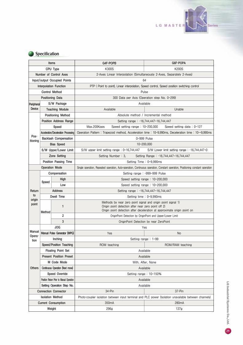
Specification
Items
CPU Type K300S K200S
64
PTP ( Point to point), Linear interpolation, Speed control, Speed position switching control
Pulse
300 Data per Axis (Operation step No. 0~299)
Available
Number of Control Axes
Input/output Occupied Points
Interpolation Function
Control Method
Positioning Data
PeripheralDevice
S/W Package
Teaching Module
Pos-itioning
Positioning Method
Position Address Range
Speed
Acceleration/Deceleration Processing
Backlash Compensation
Bias Speed
S/W Upper/Lower Limit
Zone Setting
Position Passing Time
Operation Mode
Returnto
originpoint
Compensation
SpeedHigh
Low
Address
Dwell Time
Method
1
2
3
ManualOpera-tion
JOG
Manual Pulse Generator (MPG)
Inching
Speed/Position Teaching
Others
Floating Point Set
Present Position Preset
M Code Mode
Continuous Operation (Next move)
Speed Override
Position Return Prior to Manual Operation
Setting Operation Step No.
Connection Connector
Isolation Method
Current Consumption
Weight
2-Axes Linear Interpolation (Simultaneously 2-Axes, Separately 2-Axes)
Available Unable
Absolute method / Incremental method
Setting range : -16,744,447~16,744,447
Max.200Kpps Speed setting range : 10~200,000 Speed setting data : 0~127
Operation Pattern : Trapezoid method, Acceleration time : 10~9,990ms, Deceleration time : 10-~9,990ms
0~999 Pulse
10~200,000
S/W upper limit setting range : 0~16,744,447 S/W Lower limit setting range : -16,744,447~0
Setting Number : 3, Setting Range : -16,744,447~16,744,447
Setting Time : 0~9,990ms
Single operation, Repeated operation, Auto-operation, Continuous operation, Constant operation, Positioning constant operation
Setting range : -999~999 Pulse
Speed setting range : 10~200,000
Speed setting range : 10~200,000
Setting range : -16,744,447~16,744,447
Setting time : 0~9,990ms
Methods by near zero point signal and origin point signal 1)Origin point detection after near zero point off 2)Origin point detection after deceleration at approximate origin point on
OriginPoint Detection by OriginPoint and Upper/Lower Limit
OriginPoint Detection by near ZeroPoint
Yes
NoYes
Setting range : 1~99
ROM teaching ROM/RAM teaching
Available
With, After, None
Available
Setting range : 10~150%
Available
Available
Available
34-Pin 37-Pin
Photo-coupler isolation between input terminal and PLC power (Isolation unavailable between channels)
350mA 280mA
296g 137g
G4F-POPB G6F-POPA

30
Features
System Configuration
Specification
Items
CPU Type
Analog TimerPoints
Timer Range of Setting Value
Timer Setting Method
Timer Accuracy
IndicatorOperation LED
Contact LED
Method
Internal Power Consumption
G4F-AT3A
200㎃
8 Points
8 Points
K300
0.1~1.0sec, 1~10sec, 10~60sec, 60~600sec
Setting by the adjustment volume
±2.0% (Full scale)
CR analog type (On-delay)
8 Points
SSeettttiinngg aanndd aaddjjuussttiinngg ttiimmee ooff hhiigghhllyy mmiinnuuttee rraannggee bbyy TTiimmeerr
SSeettttiinngg cciirrccuuiitt uussiinngg ffeeaattuurreess ooff aannaalloogg cciirrccuuiitt iiss aavvaaiillaabbllee
MMaaxx.. 88 PPooiinnttss ooff AAnnaalloogg TTiimmeerr ppeerr mmoodduullee aarree aapppplliiccaabbllee
WWiiddee rraannggee ooff sseettttiinngg ttiimmee (0.1sec~600sec)
EEaassyy ttiimmeerr sseettttiinngg wwiitthh oonnllyy sswwiittcchh mmaanniippuullaattiioonn
LLEEDD ddiissppllaayy ffoorr iinnddiiccaattiioonn tthhee TTiimmeerr ooppeerraattiioonn ssttaattuuss
TTiimmeerr sseettttiinngg iiss aavvaaiillaabbllee iinn rruunn mmooddee
Operating Timer
Setting Time of Timer 0 : 1secSystem Flag With 10sec cycleBase : No. 0
K300S G4F-AT3A G4Q-RY2A
Timer Chart
5sec ON5sec OFF
OFFOn After 1sec Delay
10sec Cycle
-T10S
IN
OUT
31
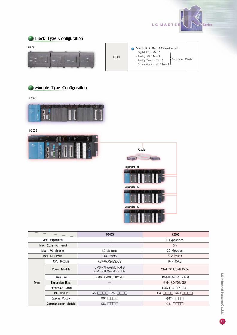
K80S
BBaassee UUnniitt ++ MMaaxx.. 33 EExxppaannssiioonn UUnniitt
- Digital I/O : Max 2
- Analog I/O : Max 2
- Analog Timer : Max 3
- Communication I/F : Max 1
Total Max. 3Made
─ G4C-E041/121/301
GM4-B04/06/08/12M
K4P-15AS
32 Modules
G4I-���� G4Q-����
G4F-����
G4L-����
512 Points
3m
G6I-���� G6Q-����
G6F-����
G6L-����
I/O Module
Special Module
Communication Module
12 Modules
─
─
GM6-PAFA/GM6-PAFBGM6-PAFC/GM6-PDFA
Block Type Configuration
Module Type Configuration
K200S
K200S K300S
─ 3 Expansions
GM4-PA1A/GM4-PA2A
GM4-B04/06/08E
Max. Expansion
Max. Expansion length
Max. I/O Module
Max. I/O Point
Type
CPU Module
Power Module
Base Unit
Expansion Base
Expansion Cable
Cable
Expansion #1
Expansion #2
Expansion #3
K300S
K80S
}
GM6-B04/06/08/12M
K3P-07AS/BS/CS
384 Points

32
General Specification Performance Specification
Items
Storage TemperatureRange
Operating TemperatureRange
Ambient HumidityRange
Operating Ambience
Dimensions
Weight
Cooling Method
-10℃~50℃
0℃~40℃
5~95% (Non-condensing)
Free from corrosive gases
90W×175H×36D
420g
Self cooling
Specifications Items
Available PLC
Power Supply
Connection MethodWith PLC
LCD Display
Key Pannel
Programming Method
MASTER-K series
Connected PLC. DC 5V 0.6A
Connected by loader cableInterface : RS-232C, 9.6Kbps (K10S1)
38.4Kbps (K80S, K200S, K300S)
16 Character, 2 line dot matrix LCDLCD BACK LIGT : On/off by key operation turnedoff Automatically After 10 Min.since last key operation
3 Mode LED, 3 Mode Key, 48 Key-keypadKey-Buzzer function - Error or key operating
- On/Off select function
On-Line : Inputs program direct PLC program
Specifications
KLD-150S
KLC-015A
KLC-010AK10S1
K80S
K200S
K300S
*Remark : K80S is available at KLD-150S Ver 4.0 or more.
33
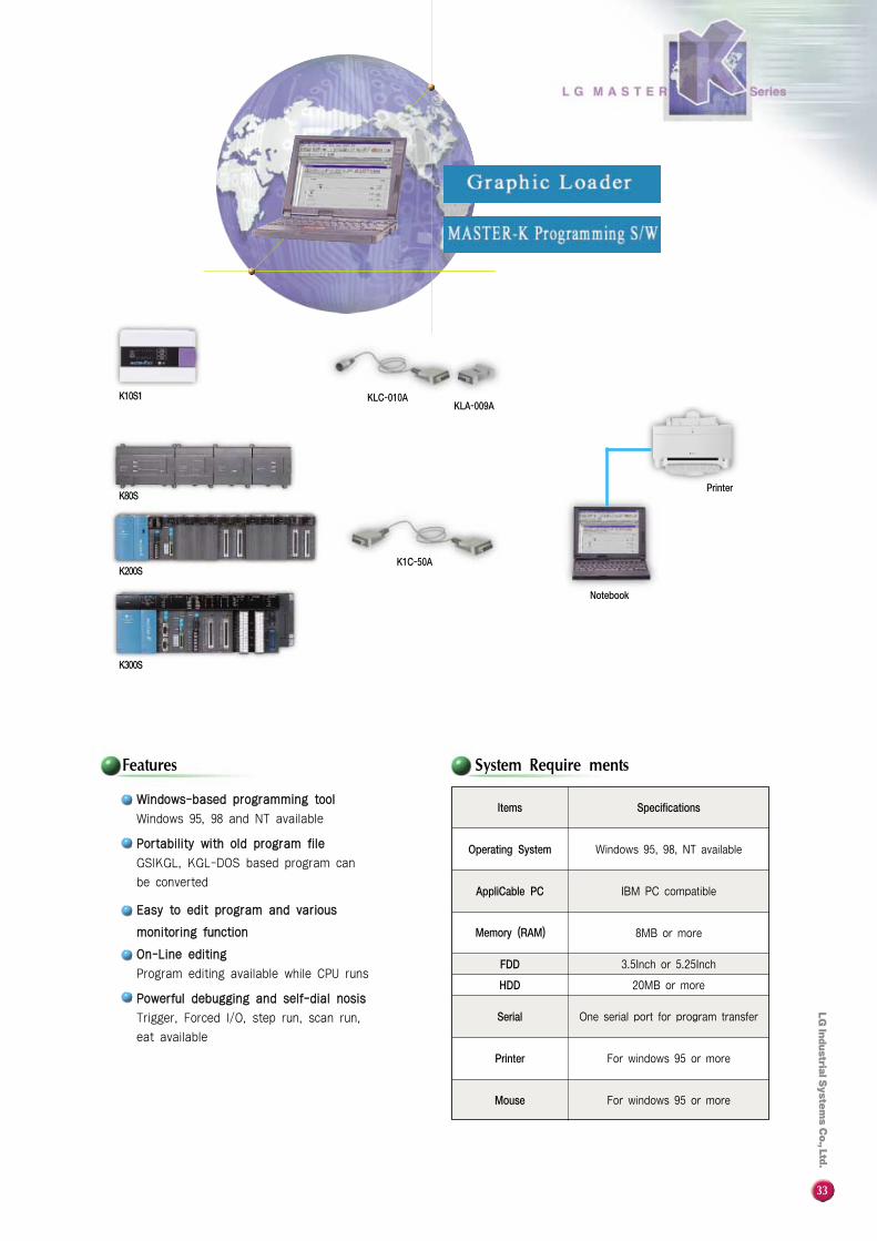
Features System Require ments
Printer
WWiinnddoowwss--bbaasseedd pprrooggrraammmmiinngg ttooooll
Windows 95, 98 and NT available
PPoorrttaabbiilliittyy wwiitthh oolldd pprrooggrraamm ffiillee
GSIKGL, KGL-DOS based program can
be converted
EEaassyy ttoo eeddiitt pprrooggrraamm aanndd vvaarriioouuss
mmoonniittoorriinngg ffuunnccttiioonn
OOnn--LLiinnee eeddiittiinngg
Program editing available while CPU runs
PPoowweerrffuull ddeebbuuggggiinngg aanndd sseellff--ddiiaall nnoossiiss
Trigger, Forced I/O, step run, scan run,
eat available
Items
Operating System
AppliCable PC
Memory (RAM)
FDD
HDD
Serial
Printer
Mouse
Windows 95, 98, NT available
IBM PC compatible
8MB or more
3.5Inch or 5.25Inch
20MB or more
One serial port for program transfer
For windows 95 or more
For windows 95 or more
Specifications
Notebook
KLA-009AKLC-010A
K1C-50A
K10S1
K80S
K200S
K300S
34
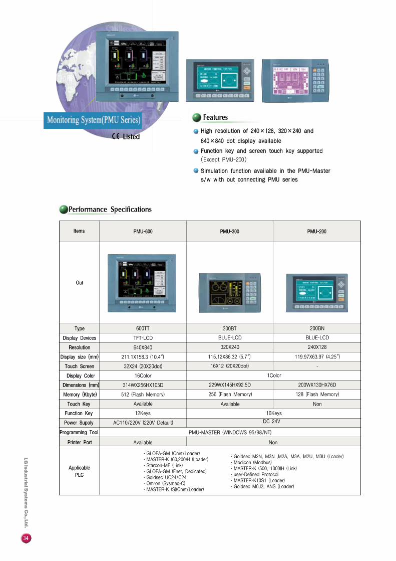
PMU-200
Performance Specifications
Features
Non
HHiigghh rreessoolluuttiioonn ooff 224400××112288,, 332200××224400 aanndd
664400××884400 ddoott ddiissppllaayy aavvaaiillaabbllee
FFuunnccttiioonn kkeeyy aanndd ssccrreeeenn ttoouucchh kkeeyy ssuuppppoorrtteedd
(Except PMU-200)
SSiimmuullaattiioonn ffuunnccttiioonn aavvaaiillaabbllee iinn tthhee PPMMUU--MMaasstteerr
ss//ww wwiitthh oouutt ccoonnnneeccttiinngg PPMMUU sseerriieess
Items
Type
Display Devices
Resolution
Display size (mm)
Touch Screen
Display Color
Dimensions (mm)
Memory (Kbyte)
Touch Key
Function Key
Power Supoly
Programming Tool
ApplicablePLC
PMU-MASTER (WINDOWS 95/98/NT)
Printer Port NonAvailable
∙GLOFA-GM (Cnet/Loader)∙MASTER-K (60,200)H (Loader)∙Starcon-MF (Link)∙GLOFA-GM (Fnet, Dedicated)∙Goldsec UC24/C24 ∙Omron (Sysmac-C)∙MASTER-K (S)(Cnet/Loader)
PMU-600 PMU-300
600TT
TFT-LCD
640X840
211.1X158.3 (10.4�)
32X24 (20X20dot)
16Color
314WX256HX105D
512 (Flash Memory)
Available
12Keys
AC110/220V (220V Default)
300BT 200BN
BLUE-LCD BLUE-LCD
320X240 240X128
115.12X86.32 (5.7�)
16X12 (20X20dot)
1Color
200WX130HX76D229WX145HX92.5D
128 (Flash Memory)256 (Flash Memory)
Available
16Keys
DC 24V
119.97X63.97 (4.25�)
-
Out
Listed
∙Goldsec M2N, M3N ,M2A, M3A, M2U, M3U (Loader)∙Modicon (Modbus)∙MASTER-K (500, 1000)H (Link)∙user-Defined Protocol ∙MASTER-K10S1 (Loader)∙Goldsec M0J2, ANS (Loader)
35
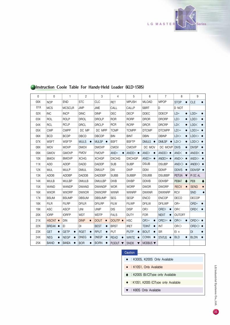
Instruction Coole Table For Handy-Held Loader (KLD-150S)
AND< ●
STOP ● CLE ●
LD= ● LDD= ●
LD> ● LDD> ●
LD< ● LDD< ●
LD>= ● LDD>= ●
LD<= ● LDD<= ●
MULSP ● BSFT DMULS ● DMILSP ● LD<> ● LDD<> ●
DIVS ● DIVSP ●
AND= ● ANDD= ● AND> ● ANDD> ● ANDD< ●
AND>= ● ANDD>= ● ANDD<= ●
AND<> ● ANDD<> ●
DDIVS ●
PIDTUN ▼
PID8AT ♠
DDIVSP ●
PI DC AL
PID8 ♠
SEND ■RECV ■
RCV SND ●
DECO DECOP
OR= ORD= ●
OR> ORD> ● OR< ORD< ●
FALS FOR NEXT ●
HSCNT ■ DIN DINP ■ DOUT ■ DOUTP ■ HSC OR>= ● ORD>= ● OR<= ● ORD<= ●
BREAK ● EI DI BEST ● BRST IRET TDINT ● INT OR<> ORD<> ●
GET ● GETP ● RGET ● RPUT ● PUT PUTP ● BOUT ● SR EI n DI ●
NEG ● NEGP ● DNEG ● DNEGP ● READ ●
PLSOUT ▼
WRITE ●
SND8 ▼
CONN ●
MODBUS ▼
STATUS ● BLD ● BLDN ●
BAND ● BANDA ● BOR ● BORN ●
0 0 1 2 3 4 5 6 7 8 9
00X NOP END STC CLC RET MPUSH MLOAD MPOP
01X MCS MCSCLR JMP JME CALL CALLP SBRT D D NOT
02X INC INCP DINC DINP DEC DECP DDEC DDECP
03X ROL ROLP DROL DROLP ROR RORP DROR DRORP
04X RCL RCLP DRCL DRCLP RCR RCRP DRCR DRCRP
05X CMP CMPP DC MP DC MPP TCMP DTCMP DTCMPP
06X BCD BCDP DBCD DBCDP BIN BINT DBIN DBINP
07X WSFT WSFTP MULS ● BSFTP
08X MOV MOVP DMOV DMOVP CMOV CMOVP DC MOV DC MOVP
09X GMOV GMOVP FMOV FMOVP
10X BMOV BMOVP XCHG XCHGP DXCHG DXCHGP AND<= ●
11X ADD ADDP DADD DADDP SUB SUBP DSUB DSUBP
12X MUL MULP DMUL DMULP DIV DIVP DDIV DDIVP
13X ADDB ADDBP DADDB DADDBP SUBB SUBBP DSUBB DSUBBP
14X MULB MULBP DMULB DMULBP DIVB DIVBP DDIVB DDIVBP
15X WAND WANDP DWAND DWANDP WOR WORP DWOR DWORP
16X WXOR WXORP DWXOR DWXORP WXNR WXNRP DWXNR DWXNRP
17X BSUM BSUMP DBSUM DBSUMP SEG SEGP ENCO ENCOP
18X FILR FILRP DFILR DFILRP FILW FILWP DFILW DFILWP
19X ASC ASCP UNI UNIP DIS DISP
20X IORP IORFP WDT WDTP DUTY OUTOFF
21X
22X
23X
24X
25X
● : K300S, K200S Only Available
■ : K10S1, Only Available
♠ : K200S (B/C)Type only Available
▼ : K80S Only Available
◆ : K10S1, K200S (C)Type only Available
TCMPP
CCaauuttiioonn

36
Type Part Number Specification Power Supply Remarks
Base K14P1-DRS ∙8 DC 24V Inputs∙6 Relay Outpus∙user program : 800 Steps AC 100~240V *1
*1 1 Buit-In High speed counter : 1 phase 8K pps*2 1 Buit-In High speed counter : 1 phase 16K pps, 2 phases 8K pps*3 K7M-DR10S (/ DC ), K7M-DT10S : built-In 1 RS-232C port and 1 RS-485 port available
K10S1
K80S
Base Unit
Exp. Pack
Exp. Module
Type Part Number Specification Power Supply Remarks
K7M-DR10S ∙6 DC 12/24V Inputs ∙4 Relay Outputs
K7M-DR20S ∙12 DC 12/24V Inputs ∙8 Relay Outputs
K7M-DR30S ∙18 DC 12/24V Inputs ∙12 Relay Outputs AC 85~264V
K7M-DR40S ∙24 DC 12/24V Inputs ∙16 Relay Outputs(Free voltage)
K7M-DR60S ∙36 DC 12/24V Inputs ∙24 Relay Outputs
K7M-DT10S ∙6 DC 12/24V Inputs ∙4 Transistor Outputs
K7M-DT20S ∙12 DC 12/24V Inputs ∙8 Transistor Outputs
K7M-DT30S ∙18 DC 12/24V Inputs ∙12 Transistor Outputs AC85~264V
K7M-DT40S ∙24 DC 12/24V Inputs ∙16 Transistor Outputs(Free voltage)
K7M-DT60S ∙36 DC 12/24V Inputs ∙24 Transistor Outputs
K7M-DR10S/ DC ∙6 DC 12/24V Inputs ∙4 Relay Outputs
K7M-DR20S/ DC ∙12 DC 12/24V Inputs ∙8 Relay Outputs DC12~24VK7M-DR30S/ DC ∙18 DC 12/24V Inputs ∙12 Relay Outputs (Free voltage)K7M-DR40S/ DC ∙24 DC 12/24V Inputs ∙16 Relay Outputs
K7M-DR60S/ DC ∙36 DC 12/24V Inputs ∙24 Relay Outputs
∙Programming capacity : 7K steps
∙1 High speed counter (16 KHz for 1 Phase, 8 KHz for 2 Phases)
∙8 PID Loops with auto Tuning
Built-In functions∙8 Pulse catch Inputs (Min. 0.2ms)
∙Discrete Inputs with filters (0~5ms, each 1ms)
∙8 External Interrupt Inputs (0.4ms)
∙1 RS-232C and 1 Loader port
(Dedicated, userdefined, Modbus protocol available)
G7E-DR10A ∙6 DC 12/24V Inputs ∙4 Relay Outputs
G7F-ADHA ∙2 Analog Inputs ∙1 Analog Outputs
G7L-CUEC ∙RS-422/485 Communication module
G7L-CUEB ∙RS-232C Communication module (Modem available)
G7L-FUEA ∙Fnet Master Module
G7F-AT2A ∙Analog potentio meter, 4 points
G7F-RTCA ∙Real time clock pack
G7M-M256 ∙Flash memory pack for program back-up (256Kbytes)
*2
*3

37
K3P-07AS CPU Module, user program memory 7K steps, Max. 384 I/O, built-in RS-232C K3P-07AS
K3P-07BS CPU Module, user program memory 7K steps, Max. 384 I/O, built-in RS-422/485, PID, RTC K3P-07BS
K3P-07CS CPU Module, user program memory 7K steps, Max. 384 I/O, built-in RS-232C, PID, HSC, RTC K3P-07CS
GM6-PAFA Power supply module, AC 85~264V, DC 5V 2A, DC 24V 0.3A (For D I/O only) K3S-302S
GM6-PAFB Power supply module, AC 85~264V, DC 5V 2A, DC -15V 0.3A (For AD/DA) K3S-304S
GM6-PDFA Power supply module, AC 12~24V, DC 5V 2A (For D I/O only) K3S-012S
GM6-PDFB Power supply module, AC 12~24V, DC 5V 3A, DC ±15V 0.3A (For AD/DA) K3S-014S
GM6-PAFC Power supply module, AC 85~132V, DC 5V 3.5A, DC 24V 0.3A (For 12 slot D I/O) -
GM6-B04M Base board, 4 slots for I/O module K3B-4MS
GM6-B06M Base board, 6 slots for I/O module K3B-6MS
GM6-B08M Base board, 8 slots for I/O module K3B-8MS
GM6-B12M Base board, 12 slots for I/O module -
G6I-D21A DC Input 8 points (current sink/source type) K3X-110S
G6I-D22A DC Input 16 points (current sink/source type) K3S-210S
G6I-D24A DC Input 32 points (current sink/source type) K3X-310S
G6I-A11A AC 110V Input 8 points module K3X-120S
G6I-A21A AC 220V Input 8 points module K3X-130S
G6Q-RY1A Relay Output 8 points (AC 240V, DC 24V 2A) K3Y-101S
G6Q-RY2A Relay Output 16 points (AC 240V, DC 24V 2A) K3Y-201S
G6Q-TR2A Tr. (NPN Type) Output 16 points (DC 12/24V 0.5A) K3Y-203S
G6Q-TR4A Tr. (NPN Type) Output 32 points (DC 12/24V 0.1A) K3Y-303S
G6Q-TR2B Tr. (PNP Type) Output 16 points (DC 12/24V 0.5A) K3Y-204S
G6Q-TR4B Tr. (PNP Type) Output 32 points (DC 12/24V 0.1A) K3Y-304S
G6Q-SS1A SSR (Current sink Type) Output 8 points (AC 100~240V 1A) K3Y-102S
G6F-AD2A Analog Input 4 channels, DC 1~5V, DC 0~10V, DC -10~+10V, DC 4~20mA K3F-AD2A
G6F-DA2V Analog Output 4 channels, DC -10~+10V K3F-AV2A
G6F-DA2I Analog Output 4 channels, DC 4~20mA K3F-DI2A
G6F-HSCA High speed count module, 1 channel (Range : 0~16,777,215) K3F-HSCA *1
G6F-POPA Position control module, 2 axis, Pulse Output, Max. 200Kpps K3F-POPA *1
G6F-CUEB Computer communication (RS-232C 1 channel) K3F-CU2A
G6F-CUEC Computer communication (RS-422 1 channel) K3F-CU4A
G6L-FUEA Fieldbus (Fnet) module, 1 Mbps (Mounted on I/O slot) K3F-FUEA
G6L-RBEA Fieldbus (Fnet) module, 1 Mbps (Mounted on CPU slot) -
GOL-SMIA Single Remote DC Input 16 points, Fieldbus (Fnet) GOL-SMIA
GOL-SMQA Single Remote Relay Output 16 points, Fieldbus (Fnet) GOLSMQA
GOL-SMHA Single Remote DC Input 8 points, Relay Output 8 points, Fieldbus (Fnet) GOLSMHA
G6F-DMMA Dummy module for empty I/O slots K3F-DMMA
K200S
K300S
CPUModules
PowerModules
BaseBoard
InputModules
OutputModules
SpecialModules
LinkModules
Dummy
Types Part Numbers Specification Old part Nos.
K4P-15AS CPU module, user program memory 15K steps, Max.512 I/O K4P-15AS
GM4-PA1A Power supply module, AC85~132V, DC 5V 4A, DC 24V 0.7A (Standard type) K4S-122S
GM4-PA2A Power supply module, AC170~264V, DC 5V 4A, DC 24V 0.7A (Standard type) K4S-132S
GM4-B04M Base board, 4 slots for I/O module K4B-4MS
GM4-BO6M Base board, 6 slots for I/O module K4B-6MS
GM4-BO8M Base board, 8 slots for I/O module K4B-8MS
GM4-B12M Base board, 12 slots for I/O module K4B-12MS
GM4-BO4E Base board (for expansion), 4 slots for I/O module K4B-4ES
GM4-BO6E Base board (for expansion), 6 slots for I/O module K4B-6ES
GM4-BO8E Base board (for expansion), 8 slots for I/O module K4B-8ES
G4M--M032 Memory pack for back-up, 32 K steps G4MM032
CPUModules
PowerModules
BaseBoard
Memory Pack
Types Part Numbers Specification Old part Nos.
*1 : Produts which has been produced before July 01, 2000 is not applicable.
38
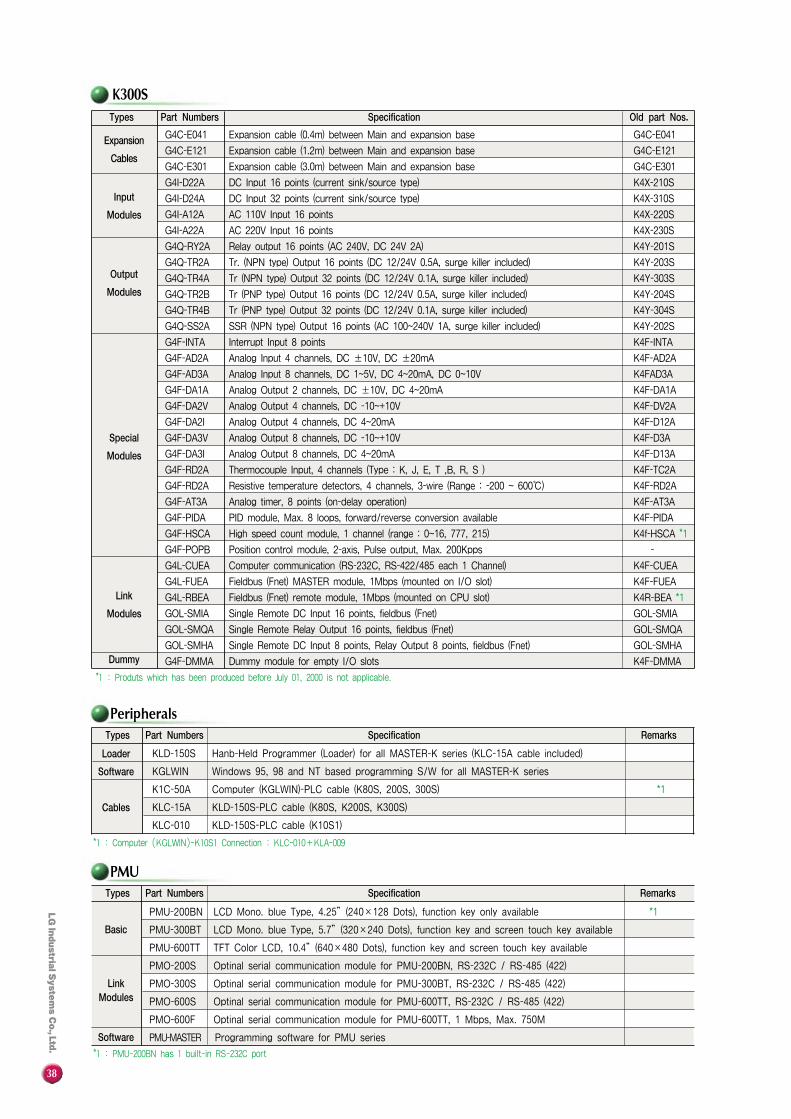
PMU
Peripherals
KLD-150S Hanb-Held Programmer (Loader) for all MASTER-K series (KLC-15A cable included)
KGLWIN Windows 95, 98 and NT based programming S/W for all MASTER-K series
K1C-50A Computer (KGLWIN)-PLC cable (K80S, 200S, 300S) *1
KLC-15A KLD-150S-PLC cable (K80S, K200S, K300S)
KLC-010 KLD-150S-PLC cable (K10S1)
Loader
Software
Cables
Types Part Numbers Specification Remarks
PMU-200BN LCD Mono. blue Type, 4.25”(240×128 Dots), function key only available *1
PMU-300BT LCD Mono. blue Type, 5.7”(320×240 Dots), function key and screen touch key available
PMU-600TT TFT Color LCD, 10.4”(640×480 Dots), function key and screen touch key available
PMO-200S Optinal serial communication module for PMU-200BN, RS-232C / RS-485 (422)
PMO-300S Optinal serial communication module for PMU-300BT, RS-232C / RS-485 (422)
PMO-600S Optinal serial communication module for PMU-600TT, RS-232C / RS-485 (422)
PMO-600F Optinal serial communication module for PMU-600TT, 1 Mbps, Max. 750M
PMU-MASTER Programming software for PMU series
Basic
LinkModules
Software
Types Part Numbers Specification Remarks
K300S
G4C-E041 Expansion cable (0.4m) between Main and expansion base G4C-E041
G4C-E121 Expansion cable (1.2m) between Main and expansion base G4C-E121
G4C-E301 Expansion cable (3.0m) between Main and expansion base G4C-E301
G4I-D22A DC Input 16 points (current sink/source type) K4X-210S
G4I-D24A DC Input 32 points (current sink/source type) K4X-310S
G4I-A12A AC 110V Input 16 points K4X-220S
G4I-A22A AC 220V Input 16 points K4X-230S
G4Q-RY2A Relay output 16 points (AC 240V, DC 24V 2A) K4Y-201S
G4Q-TR2A Tr. (NPN type) Output 16 points (DC 12/24V 0.5A, surge killer included) K4Y-203S
G4Q-TR4A Tr (NPN type) Output 32 points (DC 12/24V 0.1A, surge killer included) K4Y-303S
G4Q-TR2B Tr (PNP type) Output 16 points (DC 12/24V 0.5A, surge killer included) K4Y-204S
G4Q-TR4B Tr (PNP type) Output 32 points (DC 12/24V 0.1A, surge killer included) K4Y-304S
G4Q-SS2A SSR (NPN type) Output 16 points (AC 100~240V 1A, surge killer included) K4Y-202S
G4F-INTA Interrupt Input 8 points K4F-INTA
G4F-AD2A Analog Input 4 channels, DC ±10V, DC ±20mA K4F-AD2A
G4F-AD3A Analog Input 8 channels, DC 1~5V, DC 4~20mA, DC 0~10V K4FAD3A
G4F-DA1A Analog Output 2 channels, DC ±10V, DC 4~20mA K4F-DA1A
G4F-DA2V Analog Output 4 channels, DC -10~+10V K4F-DV2A
G4F-DA2I Analog Output 4 channels, DC 4~20mA K4F-D12A
G4F-DA3V Analog Output 8 channels, DC -10~+10V K4F-D3A
G4F-DA3I Analog Output 8 channels, DC 4~20mA K4F-D13A
G4F-RD2A Thermocouple Input, 4 channels (Type : K, J, E, T ,B, R, S ) K4F-TC2A
G4F-RD2A Resistive temperature detectors, 4 channels, 3-wire (Range : -200 ~ 600℃) K4F-RD2A
G4F-AT3A Analog timer, 8 points (on-delay operation) K4F-AT3A
G4F-PIDA PID module, Max. 8 loops, forward/reverse conversion available K4F-PIDA
G4F-HSCA High speed count module, 1 channel (range : 0~16, 777, 215) K4f-HSCA *1
G4F-POPB Position control module, 2-axis, Pulse output, Max. 200Kpps -
G4L-CUEA Computer communication (RS-232C, RS-422/485 each 1 Channel) K4F-CUEA
G4L-FUEA Fieldbus (Fnet) MASTER module, 1Mbps (mounted on I/O slot) K4F-FUEA
G4L-RBEA Fieldbus (Fnet) remote module, 1Mbps (mounted on CPU slot) K4R-BEA *1
GOL-SMIA Single Remote DC Input 16 points, fieldbus (Fnet) GOL-SMIA
GOL-SMQA Single Remote Relay Output 16 points, fieldbus (Fnet) GOL-SMQA
GOL-SMHA Single Remote DC Input 8 points, Relay Output 8 points, fieldbus (Fnet) GOL-SMHA
G4F-DMMA Dummy module for empty I/O slots K4F-DMMA
Expansion
Cables
Input
Modules
Output
Modules
Special
Modules
Link
Modules
Dummy
Types Part Numbers Specification Old part Nos.
*1 : Produts which has been produced before July 01, 2000 is not applicable.
*1 : Computer (KGLWIN)-K10S1 Connection : KLC-010+KLA-009
*1 : PMU-200BN has 1 built-in RS-232C port
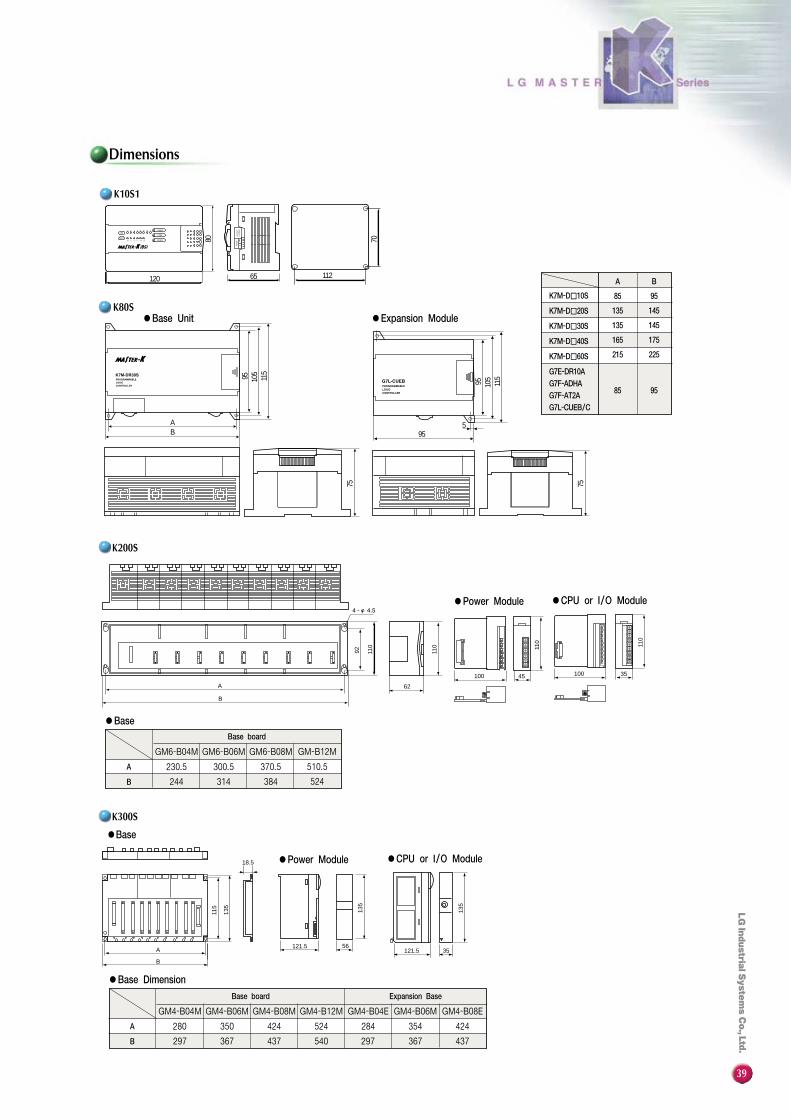
39
IN
OUT
0 1 2 3 4 5 6 7
10 11 12 13 14 15
PWR
ERR
RUN
RS232C
LOADER
RS485
65 112
70
120
80
75 75
955
95 105
115
95 105
115
AB
K10S1
Dimensions
●Base Unit ●Expansion Module
K7M-D�10S
K7M-D�20S
K7M-D�30S
K7M-D�40S
K7M-D�60S
G7E-DR10A
G7F-ADHA
G7F-AT2A
G7L-CUEB/C
540
GM4-B12M
524424
GM4-B08M
230.5
244 314 524384B
Base board
A
B
62
45100
92 110
110 11
0
35100
110
A
115
135
135
B
18.5
121.5 5635121.5
135
GM4-B04M
280
297
GM4-B06M
350
367 437
A
B
300.5 370.5 510.5A
GM6-B04M GM6-B06M GM6-B08M GM-B12M
●Power Module
●Base
●Base Dimension
●CPU or I/O Module
K200S
K300S
437
354
GM4-B06MGM4-B04E
284
297
GM4-B08E
424
367
K80S
●Power Module
●Base
●CPU or I/O Module
Base board Expansion Base
A
85
135
135
165
215
85
B
95
145
145
175
225
95
MASTER-K 2001 / Nov. 2002 Printed in Korea staff
MK 문표지 2004.3.12 10:10 AM 페이지1
Copyright © 2022 FDOKUMEN