New Breed of Network Fault-Tolerant Voltage-Source-Converter HVDC Transmission System
12
IEEE TRANSACTIONS ON POWER SYSTEMS, VOL. 28, NO. 1, FEBRUARY 2013 335 New Breed of Network Fault-Tolerant Voltage-Source-Converter HVDC Transmission System Grain Philip Adam, Member, IEEE, Khaled H. Ahmed, Member, IEEE, Stephen J. Finney, Keith Bell, and Barry W. Williams Abstract—This paper proposes a new breed of high-voltage dc (HVDC) transmission systems based on a hybrid multilevel voltage source converter (VSC) with ac-side cascaded H-bridge cells. The proposed HVDC system offers the operational flexibility of VSC- based systems in terms of active and reactive power control, black- start capability, in addition to improved ac fault ride-through capa- bility and the unique feature of current-limiting capability during dc side faults. Additionally, it offers features such as smaller foot- print and a larger active and reactive power capability curve than existing VSC-based HVDC systems, including those using modular multilevel converters. To illustrate the feasibility of the proposed HVDC system, this paper assesses its dynamic performance during steady-state and network alterations, including its response to ac and dc side faults. Index Terms—DC fault reverse blocking capability, hybrid mul- tilevel converter with ac side cascaded H-bride cells, modular mul- tilevel converter, voltage-source-converter high-voltage dc (VSC- HVDC) transmission system. I. INTRODUCTION I N the last decade, voltage-source-converter high-voltage dc (VSC-HVDC) transmission systems have evolved from simple two-level converters to neutral-point clamped converters and then to true multilevel converters such as modular con- verters [1]–[5]. This evolution aimed to lower semiconductor losses and increase power-handling capability of VSC-HVDC transmission systems to the level comparable to that of conven- tional HVDC systems based on thyristor current-source con- verters, improved ac side waveform quality in order to mini- mize or eliminate ac filters, reduced voltage stresses on con- verter transformers, and reduced converter overall cost and foot- print [6]–[15]. Manuscript received October 14, 2011; revised November 01, 2011, November 01, 2011, January 16, 2012, and February 27, 2012; accepted May 04, 2012. Date of publication July 03, 2012; date of current version January 17, 2013. Paper no. TPWRS-00967-2011. G. P. Adam, S. J. Finney, K. Bell, and B. W. Williams are with the Power Electronics, Drives and Energy Conversions Group, Institute of Energy and Environment, University of Strathclyde, Glasgow, G1 1XW U.K. (e-mail: [email protected]; s.fi[email protected]; [email protected]; barry.williams@ eee.strath.ac.uk). K. H. Ahmed is with the Electrical Engineering Department, University of Aberdeen, Aberdeen, AB24 3UE U.K. (e-mail: [email protected]). Color versions of one or more of the figures in this paper are available online at http://ieeexplore.ieee.org. Digital Object Identifier 10.1109/TPWRS.2012.2199337 With increased demand for clean energy, power system net- works need to be reengineered to be more efficient and flex- ible and reinforced to accommodate increased penetration of renewable power without compromising system operation and reliability. A VSC-HVDC transmission system is a candidate to meet these challenges due to its operational flexibility, such as pro- vision of voltage support to ac networks, its ability to operate independent of ac network strength therefore makes it suitable for connection of weak ac networks such as offshore wind farms, suitability for multiterminal HVDC network realization as active power reversal is achieved without dc link voltage polarity change, and resiliency to ac side faults (no risk of commutation failure as with line-commutating HVDC systems) [12], [16]–[22]. However, vulnerability to dc side faults and absence of reliable dc circuit breakers capable of operating at high-voltage restrict their application to point-to-point connection. Present VSC-HVDC transmission systems rely on their con- verter station control systems and effective impedance between the point-of-common-coupling (PCC) and the converter termi- nals to ride-through dc side faults. With present converter tech- nology, the dc fault current comprises the ac networks contribu- tion through converter free-wheeling diodes and discharge cur- rents of the dc side capacitors (dc link and cable distributed ca- pacitors) [23], [24]. The magnitude of the dc-side capacitors’ discharge current decays with time and is larger than the ac net- works contribution. For this reason, dc fault interruption may require dc circuit breakers that can tolerate high let-through cur- rent that may flow in the dc side during the first few cycles after the fault, with high current breaking capacity and fast interrup- tion time. Recent HVDC converter topologies with no common dc link capacitors, such as the modular multilevel converter (M2C), may minimize the magnitude and duration of the dis- charge current first peak [2], [12], [14], [23], [25]. There are two approaches to assist VSC-HVDC transmis- sion systems to ride-through dc side faults. The first approach is to use a fast acting dc circuit breaker, with considerably high let-through current to tolerate the high dc fault discharge current that may flow in the dc side. This breaker must be capable of operating at high voltage and isolates temporary or permanent dc faults, plus have a relatively high-current-breaking capacity. Reference [26] presents a prototype 80-kV dc circuit breaker with dc current breaking capacity of 9 kA within 2 ms. However, this first step is inadequate, as the operating voltage of present 0885-8950/$31.00 © 2012 IEEE
-
Upload
independent -
Category
Documents
-
view
1 -
download
0
Transcript of New Breed of Network Fault-Tolerant Voltage-Source-Converter HVDC Transmission System

IEEE TRANSACTIONS ON POWER SYSTEMS, VOL. 28, NO. 1, FEBRUARY 2013 335
New Breed of Network Fault-TolerantVoltage-Source-Converter HVDC
Transmission SystemGrain Philip Adam, Member, IEEE, Khaled H. Ahmed, Member, IEEE, Stephen J. Finney, Keith Bell, and
Barry W. Williams
Abstract—This paper proposes a new breed of high-voltage dc(HVDC) transmission systems based on a hybridmultilevel voltagesource converter (VSC) with ac-side cascaded H-bridge cells. Theproposed HVDC system offers the operational flexibility of VSC-based systems in terms of active and reactive power control, black-start capability, in addition to improved ac fault ride-through capa-bility and the unique feature of current-limiting capability duringdc side faults. Additionally, it offers features such as smaller foot-print and a larger active and reactive power capability curve thanexisting VSC-basedHVDC systems, including those usingmodularmultilevel converters. To illustrate the feasibility of the proposedHVDC system, this paper assesses its dynamic performance duringsteady-state and network alterations, including its response to acand dc side faults.
Index Terms—DC fault reverse blocking capability, hybrid mul-tilevel converter with ac side cascaded H-bride cells, modular mul-tilevel converter, voltage-source-converter high-voltage dc (VSC-HVDC) transmission system.
I. INTRODUCTION
I N the last decade, voltage-source-converter high-voltagedc (VSC-HVDC) transmission systems have evolved from
simple two-level converters to neutral-point clamped convertersand then to true multilevel converters such as modular con-verters [1]–[5]. This evolution aimed to lower semiconductorlosses and increase power-handling capability of VSC-HVDCtransmission systems to the level comparable to that of conven-tional HVDC systems based on thyristor current-source con-verters, improved ac side waveform quality in order to mini-mize or eliminate ac filters, reduced voltage stresses on con-verter transformers, and reduced converter overall cost and foot-print [6]–[15].
Manuscript received October 14, 2011; revised November 01, 2011,November 01, 2011, January 16, 2012, and February 27, 2012; accepted May04, 2012. Date of publication July 03, 2012; date of current version January 17,2013. Paper no. TPWRS-00967-2011.G. P. Adam, S. J. Finney, K. Bell, and B. W. Williams are with the
Power Electronics, Drives and Energy Conversions Group, Institute ofEnergy and Environment, University of Strathclyde, Glasgow, G1 1XWU.K. (e-mail: [email protected]; [email protected];[email protected]; barry.williams@ eee.strath.ac.uk).K. H. Ahmed is with the Electrical Engineering Department, University of
Aberdeen, Aberdeen, AB24 3UE U.K. (e-mail: [email protected]).Color versions of one or more of the figures in this paper are available online
at http://ieeexplore.ieee.org.Digital Object Identifier 10.1109/TPWRS.2012.2199337
With increased demand for clean energy, power system net-works need to be reengineered to be more efficient and flex-ible and reinforced to accommodate increased penetration ofrenewable power without compromising system operation andreliability.A VSC-HVDC transmission system is a candidate to meet
these challenges due to its operational flexibility, such as pro-vision of voltage support to ac networks, its ability to operateindependent of ac network strength therefore makes it suitablefor connection of weak ac networks such as offshore windfarms, suitability for multiterminal HVDC network realizationas active power reversal is achieved without dc link voltagepolarity change, and resiliency to ac side faults (no risk ofcommutation failure as with line-commutating HVDC systems)[12], [16]–[22]. However, vulnerability to dc side faults andabsence of reliable dc circuit breakers capable of operatingat high-voltage restrict their application to point-to-pointconnection.Present VSC-HVDC transmission systems rely on their con-
verter station control systems and effective impedance betweenthe point-of-common-coupling (PCC) and the converter termi-nals to ride-through dc side faults. With present converter tech-nology, the dc fault current comprises the ac networks contribu-tion through converter free-wheeling diodes and discharge cur-rents of the dc side capacitors (dc link and cable distributed ca-pacitors) [23], [24]. The magnitude of the dc-side capacitors’discharge current decays with time and is larger than the ac net-works contribution. For this reason, dc fault interruption mayrequire dc circuit breakers that can tolerate high let-through cur-rent that may flow in the dc side during the first few cycles afterthe fault, with high current breaking capacity and fast interrup-tion time. Recent HVDC converter topologies with no commondc link capacitors, such as the modular multilevel converter(M2C), may minimize the magnitude and duration of the dis-charge current first peak [2], [12], [14], [23], [25].There are two approaches to assist VSC-HVDC transmis-
sion systems to ride-through dc side faults. The first approachis to use a fast acting dc circuit breaker, with considerably highlet-through current to tolerate the high dc fault discharge currentthat may flow in the dc side. This breaker must be capable ofoperating at high voltage and isolates temporary or permanentdc faults, plus have a relatively high-current-breaking capacity.Reference [26] presents a prototype 80-kV dc circuit breakerwith dc current breaking capacity of 9 kAwithin 2ms. However,this first step is inadequate, as the operating voltage of present
0885-8950/$31.00 © 2012 IEEE

336 IEEE TRANSACTIONS ON POWER SYSTEMS, VOL. 28, NO. 1, FEBRUARY 2013
Fig. 1. Hybrid voltage multilevel converter with ac side cascaded H-bridge cells.
VSC-HVDC transmission systems reach 640 kV pole-to-pole(or 320 kV for a bi-polar configuration), with power-handlingcapability of 1 GW. This breaker approach may introduce sig-nificant steady-state losses due to the semiconductors in themain current path.The second approach is to use converter stations with dc fault
reverse-blocking capability [1], [4], [23]. Each converter stationmust be able to block current flow between the ac and dc sidesduring a dc fault, allowing dc-side capacitor discharge current,which is the major component of the dc fault current, to decay tozero and then isolate the fault. Several converter topologies withthis inherent feature have been proposed, including an H-bridgemodular multilevel converter, an alternative arm modular mul-tilevel converter, and a hybrid multilevel converter with ac-sidecascaded H-bridge cells. However, the drawback is that the ac-tive power exchange between the ac networks reduces to zeroduring the dc fault period.Commensurate with the second approach, this paper
presents a new HVDC transmission systems based on ahybrid-voltage-source multilevel converter with ac-side cas-caded H-bridge cells. The adopted converter has inherent dcfault reverse-blocking capability, which can be exploited toimprove VSC-HVDC resiliency to dc side faults. With coordi-nation between the HVDC converter station control functions,the dc fault reverse-blocking capability of the hybrid converteris exploited to achieve the following:• eliminate the ac grid contribution to the dc fault, henceminimizing the risk of converter failure due to uncontrolledovercurrent during dc faults;
• facilitate controlled recovery without interruption of theVSC-HVDC system from dc-side faults without the needfor opening ac-side circuit breakers;
• simplify dc circuit breaker design due to a reduction in themagnitude and duration of the dc fault current; and
• improve voltage stability of the ac networks as converterreactive power consumption is reduced during dc-sidefaults.
Section II of this paper describes the operational principle andcontrol of the hybrid voltage source multilevel converter withac-side cascaded H-bridge cells.Section III describes the HVDC system control design,
specifically, ac current controller in synchronous referenceframe, dc link voltage, and active power, and ac voltagecontrollers. A detailed block diagram that summarizes howdifferent control layers of the proposed HVDC transmissionsystem are interfaced is presented.Section IV presents simulations of a hybrid converter HVDC
transmission system, which demonstrate its response duringsteady-steady and network disturbances. Included are simu-lations of four quadrant operation, voltage support capability,and ac and dc fault ride-through capabilities.
II. HYBRID MULTILEVEL VSC WITH AC-SIDE CASCADEDH-BRIDGE CELLS
Fig. 1 shows one phase of a hybrid multilever VSC withH-bridge cells per phase. It can generate voltage
levels at converter terminal “a” relative to supply midpoint“0.” Therefore, with a large number of cells per phase, theconverter presents near pure sinusoidal voltage to the convertertransformer as depicted in Fig. 1 [1]. The two-level converterthat blocks high-voltage controls the fundamental voltageusing selective harmonic elimination (SHE) with one notchper quarter cycle, as shown in Fig. 1. Therefore, the two-levelconverter devices operate with 150-Hz switching losses, hencelow switching losses and audible noise are expected. TheH-bridge cells between “M” and “a” are operated as a seriesactive power filter to attenuate the voltage harmonics produced

ADAM et al.: NEW BREED OF NETWORK FAULT-TOLERANT VOLTAGE-SOURCE-CONVERTER HVDC TRANSMISSION SYSTEM 337
by the two-level converter bridge. These H-bridge cells are con-trolled using level-shifted carrier-based multilevel pulsewidthmodulation with a 1-kHz switching frequency. To minimizethe conversion losses in the H-bridge cells, the number of cellsis reduced such that the voltage across the H-bridge floatingcapacitors sum to . This may result in a small con-verter station, because the number of H-bridge cells requiredper converter with the proposed HVDC system is one quarterof those required for a system based on the modular multilevelconverter. With a large number of cells per phase, the voltagewaveform generated across the H-bridge cells is as shownin Fig. 1, and an effective switching frequency per device ofless than 150 Hz is possible. The dc fault reverse-blockingcapability of the proposed HVDC system is achieved by in-hibiting the gate signals to the converter switches, therefore nodirect path exists between the ac and dc side through freewheeldiodes, and cell capacitor voltages will oppose any currentflow from one side to another. Consequently, with no currentflows, there is no active and reactive power exchange betweenac and dc side during dc-side faults. This dc fault aspect meanstransformer coupled H-bridges cannot be used. The ac gridcontribution to dc-side fault current is eliminated, reducing therisk of converter failure due to increased current stresses in theswitching devices during dc-side faults. From the grid stand-point, the dc fault reverse-blocking capability of the proposedHVDC system may improve ac network voltage stability, asthe reactive power demand at converter stations during dc-sidefaults is significantly reduced. The ac networks see the nodeswhere the converter stations are connected as open circuitnodes during the entire dc fault period. However, operation ofthe hybrid multilevel VSC requires a voltage-balancing schemethat ensures that the voltages across the H-bridge cells aremaintained at under all operating conditions, whereis the total dc link voltage. The H-bridge cells voltage balancingscheme is realized by rotating the H-bridge cell capacitors,taking into account the voltage magnitude of each cell capacitorand phase current polarity. An additional PI regulator is usedto ensure that the cell capacitors be maintained at asdepicted in Fig. 2(b) (inner control layer).
III. CONTROL SYSTEMS
A HVDC transmission system based on a hybrid multilevelVSC with ac-side cascaded H-bridge cells requires three controlsystem layers. The inner control layer represents the modulatorand capacitor voltage-balancing mechanism that generates thegating signals for the converter switches and maintains voltagebalance of the H-bridge cell capacitors. The intermediate controllayer represents the current controller that regulates the activeand reactive current components over the full operating rangeand restraints converter station current injection into ac networkduring network disturbances such as ac and dc side faults. Theouter control layer is the dc voltage (or active power) and acvoltage (or reactive power) controller that provide set points tothe current controllers. The inner controller has only been dis-cussed to a level appropriate to power systems engineers. Theintermediate and outer control layers are presented in detail to
give the reader a sense of HVDC control system complexity.The current, power, and dc link voltage controller gains are se-lected using root locus analysis, based on the applicable transferfunctions. Some of the controller gains obtained using root locusanalysis give good performance in steady state but failed to pro-vide acceptable network disturbance performance. Therefore,the simulation final gains used are adjusted in the time domain toprovide satisfactory performance over a wide operating range,including ac and dc side faults. Fig. 2 summarizes the controllayers of the hybrid multilevel VSC.Current Controller Design: The differential equations de-
scribing the ac-side transient and steady-state are
(1)
(2)
Assume
and
(3)
(4)
The new control variables and can be obtained from twoproportion-integral controllers (PI) having the same gains:
(5)
(6)
where and represent reference direct and quadrature cur-rent components.To facilitate control design in state space, the integral parts ofand are replaced by and
, rearranged in the following form:
(7)
(8)
The integral parts, in differential equations form, are
(9)
(10)
After substitution of (7) and (8) into (3) and (4), two identicaland independent sets of equations, suitable for control design,are obtained as
(11)
(12)

338 IEEE TRANSACTIONS ON POWER SYSTEMS, VOL. 28, NO. 1, FEBRUARY 2013
Fig. 2. (a) Representation of VSC station and (b) schematic diagram summarizing the control layer of the hybrid multilevel converter with ac side cascadedH-bridge cells
After Laplace manipulations of the state-space equations in(11) and (12), one transfer function is obtained for and ,which is used for the current controller design
Equations relating the reference voltages to themodulatorand , current controller output, and feedforward terms can beobtained from expressions for and as follows:
(13)
(14)
Based on (5), (6), (13), and (14), the structure of the currentcontroller shown in Fig. 2(b) (intermediate layer) is obtained.DC Voltage Controller: Based on Fig. 2, the differential
equation describing the converter dc-side dynamics is
(15)
Assuming a lossless VSC, dc power at the converter dc linkmust equal the ac power at converter terminal
. Therefore, (15) can be written as
(16)

ADAM et al.: NEW BREED OF NETWORK FAULT-TOLERANT VOLTAGE-SOURCE-CONVERTER HVDC TRANSMISSION SYSTEM 339
Equation (16) can be linearized using a Taylor series with thehigher order terms neglected. Therefore, the linearized form of(16) is
(17)
Let and
and the variable can be obtained from theDC voltage controller based on the PI control as follows:
(18)Equation (17) can be reduced to
(19)
where represents reference dc link voltage.Let the new control variable introduced for the integral part
of the dc voltage controller be , therefore:
(20)
(21)
The state equations in (20) and (21) in matrix form are:
(22)Equation (22) in the s-domain is
(23)where
(24)
From (24), the transfer function for the dc voltage controlleris
(25)
Normally, the voltage angle at the converter terminal rela-tive to the PCC is sufficiently small, resulting in and
. Therefore, the reference current for the currentcontroller can be obtained from the outer dc voltage controlleras follows:
(26)
where and are normalized by .Active Power Controller: The active power controller sets
the reference active current component assuming a constantvoltage at the PCC as follows:
(27)
Assume the voltage vector at the PCC is aligned with the-axis and its magnitude is regulated at as , andrepresents active power reference. After replacing the inte-
gral part with a new control variable , the following sets ofequations result:
(28)
(29)
After substituting (28) into (11), the following state space rep-resentation for the power controller is obtained:
where we have (30), shown at the bottom of the page.AC Voltage Controller: The reference reactive power current
component is set by the ac voltage controller as
where represents reference voltage magnitude at PCC.However, the gains for the ac voltage controllers are obtainedusing a trial0and-error search method that automatically runsthe overall system simulation several times in an attempt to findthe gains that produce the best time domain performance. The
(30)

340 IEEE TRANSACTIONS ON POWER SYSTEMS, VOL. 28, NO. 1, FEBRUARY 2013
TABLE ICONVERTER STATIONS PARAMETERS
TABLE IICONVERTER TRANSFORMER PARAMETERS
TABLE IIITRANSMISSION SYSTEMS PARAMETERS
gains for all of the controllers and test network parameters usedin this paper are listed in Tables I–III.
IV. PERFORMANCE EVALUATION
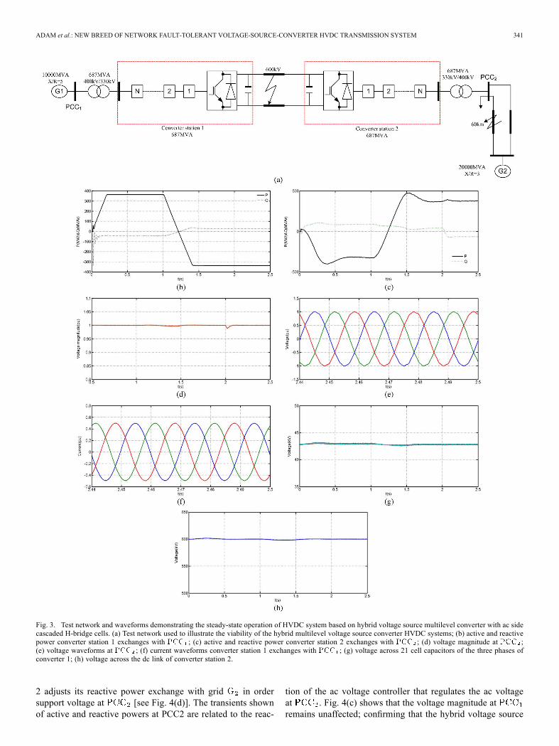
The viability of the VSC-HVDC system that uses a hybridmultilevel VSC with ac-side cascaded H-bridge cells is inves-tigated here, with emphasis on its dynamic performance duringnetwork alterations. In the steady state, the test network inFig. 3(a) is used to assess its power control and voltage supportcapabilities. To further illustrate the advantages of the hybridmultilevel converter during ac and dc network disturbances,the same test network is subjected to a three-phase ac-sidefault and a pole-to-pole dc-side fault at locations depicted inFig. 3(a), both for a 140-ms duration. Converter stations 1 and2 in Fig. 3(a) are represented by detailed hybrid VSC modelswith seven cells per phase, with the controllers in Fig. 2(b)incorporated.Seven cells per arm are used in this paper in orderto achieve acceptable simulation times without compromisingresult accuracy, as each system component is represented indetailed. Also, the hybrid converter with seven H-bridge cells
per phase generates 29 voltage levels per phase, which is thesame as the two-switch modular multilevel converter with 28cells per arm, for the same dc link voltage such that devicesin both converters experience the same voltage stresses. Theconverters are configured to regulate active power exchangeand dc link voltage, and ac voltage magnitudes at and
respectively. The test system in Fig. 3(a) is simulated inthe MATLAB Simulink environment.
A. Four-Quadrant Operation and Voltage Support
To demonstrate four0quadrant operation and voltage supportcapability of the presented VSC-HVDC system, converter sta-tion 1 is commanded to increase its output power export fromgrid to from 0 to 0.5 pu (343.5 MW) at 2.5 pu/s. Attime 1 s it is commanded to reverse the active power flowin order to import 343.5 MW from grid , at 2.5 pu/s. At
a load of is introduced to , il-lustrating the voltage support capability of converter station 2during network alteration.Fig. 3(b) and (c) show converters 1 and 2 active and reactive
power exchange with and respectively. Theconverters are able to adjust their reactive power exchange with
and in order to support the voltage during theentire operating period. Fig. 3(c) and (d) show that converter2 adjusts its reactive power exchange with when theload is introduced at 2 s to support the voltage magnitude.Fig. 3(e) and (f) show that converter 2 injects and presentshigh-quality current and voltage waveforms into withno ac filters installed). Fig. 3(g) demonstrates that the voltagestresses across the H-bridge cell capacitors of converter 1 arecontrolled to the desired set point during the entire period.Fig. 3(h) displays the total dc link voltage across converter 2,which regulates the dc link voltage. Based on these results, theproposed VSC-HVDC system is able to meet basic steady-staterequirements, such as provision of voltage support and fourquadrant operation without compromising the voltage andcurrent stresses on the converters switches.
B. AC Network Faults
To demonstrate the ac fault ride-through capability of the pre-sented HVDC system, the test network is subjected to a 140 msthree-phase fault to ground at the location shown in Fig. 3(a).During the fault period the power command to converter 1 isreduced in proportion to the reduction in the ac voltage mag-nitude (this is achieved by sensing voltage). This is tominimize the two-level converter dc link voltage rise because ofthe trapped energy in the dc side, since power cannot be trans-ferred as the voltage at collapses. Fig. 4 displays the re-sults when the test network exports 0.5 pu (343.5 MW) fromgrid to and is subjected to the three-phase fault at .Fig. 4(a) shows the active and reactive powers converter 1 ex-changes with . Note that converter 1 matches its activepower export to in order to minimize the rise of converter2 dc link voltage as its ability to inject active power into grid
reduces with the voltage collapse at , as shown inFig. 4(d) and stated above. Fig. 4(b) shows the active and re-active powers that converter 2 injects into . The systemis able to recover as soon as the fault is cleared, and converter
ADAM et al.: NEW BREED OF NETWORK FAULT-TOLERANT VOLTAGE-SOURCE-CONVERTER HVDC TRANSMISSION SYSTEM 341
Fig. 3. Test network and waveforms demonstrating the steady-state operation of HVDC system based on hybrid voltage source multilevel converter with ac sidecascaded H-bridge cells. (a) Test network used to illustrate the viability of the hybrid multilevel voltage source converter HVDC systems; (b) active and reactivepower converter station 1 exchanges with ; (c) active and reactive power converter station 2 exchanges with ; (d) voltage magnitude at ;(e) voltage waveforms at ; (f) current waveforms converter station 1 exchanges with ; (g) voltage across 21 cell capacitors of the three phases ofconverter 1; (h) voltage across the dc link of converter station 2.
2 adjusts its reactive power exchange with grid in ordersupport voltage at [see Fig. 4(d)]. The transients shownof active and reactive powers at PCC2 are related to the reac-
tion of the ac voltage controller that regulates the ac voltageat . Fig. 4(c) shows that the voltage magnitude atremains unaffected; confirming that the hybrid voltage source

342 IEEE TRANSACTIONS ON POWER SYSTEMS, VOL. 28, NO. 1, FEBRUARY 2013
Fig. 4. Waveforms demonstrating ac fault ride-through capability of HVDC transmission systems based on hybrid voltage multilevel converter with ac sidecascaded H-bridge cells. (a) Active and reactive power converter 1 exchanges with . (b) Active and reactive power converter 2 injects into . (c)Voltage magnitude at . (d) Voltage magnitude at . (e) Current waveforms converter 2 injects into . (f) Converter 2 dc link voltage. (g) Voltageacross 21 H-bridge cells of the converter 2. (h) Line-to-line voltage waveform at the terminal of converter 1 (before transformer). (i) Active and reactive power atPCC1. (j) Active and reactive power at PCC2. Results in (i)–(o) demonstrate the case when the converter stations operate close to their maximum active powercapabilities (power command at converter 1 is set to 0.75 pu, which is 515 MW) and system is subjected to a three-phase fault with a 300-ms duration.
multilevel converter does not compromise the HVDC transmis-sion system’s decoupling feature despite adopting active powermatching at converter 1, as explained. Fig. 4(e) shows that con-verter 2 restrains its contribution to the fault current to less
than full load current despite the voltage at collapsing to20% of its rated voltage, due to converter 2’s current controller.Fig. 4(f) shows that coordination of the HVDC controllers, as il-lustrated, minimizes the impact of ac-side faults on the transient

ADAM et al.: NEW BREED OF NETWORK FAULT-TOLERANT VOLTAGE-SOURCE-CONVERTER HVDC TRANSMISSION SYSTEM 343
Fig. 4. (Continued.) Waveforms demonstrating ac fault ride-through capability of HVDC transmission systems based on hybrid voltage multilevel converterwith ac side cascaded H-bridge cells. (k) Voltage magnitude at PCC1. (l) Voltage magnitude at PCC2. (m) Current waveforms converter 2 injects into PCC2.(n) Converter 2 dc link voltage. (o) Voltage across the 21 H-bridge cell capacitors of converter 2. Results in (i)–(o) demonstrate the case when the converterstations operate close to their maximum active power capabilities (power command at converter 1 is set to 0.75 pu, which is 515 MW) and system is subjected toa three-phase fault with a 300-ms duration.
power flow on the dc side, hence minimizing disturbance on thedc link voltage. Fig. 4(g) shows that the H-bridge cell voltagestresses are controlled as the system rides through the ac-sidefault. This confirms that the complexity of a HVDC systembased on the hybrid multilevel VSC does not compromise its acfault ride-through capability. Fig. 4(h) shows the hybrid multi-level VSC presents high-quality voltage to the converter trans-former, with low harmonic content and . This may permitelimination of ac-side filters and the use of standard insulationac transmission transformers.The results in Fig. 4(i)–(o) are presented to demonstrate the
ability of the proposed HVDC system to operate in faulty net-works, independent of its operating point and fault duration.This case demonstrates the superiority of current-limiting VSCsover a synchronous generator during ac network disturbances.(Converter 2 current injection into is always controlledand less than full load rated current despite the fault durationand the amount of power exchange between ac networksand .)
C. DC Network Faults
The inherent current-limiting capability of the hybrid mul-tilevel VSC with ac-side cascaded H-bridge cells that permitsthe VSC-HVDC system to ride-through dc-side faults will
be demonstrated here. The test network is subjected to a 140ms solid pole-to-pole dc-side fault at the location indicatedin Fig. 3(a). During the dc-side fault period, active powerexchange between the two grids and is reduced to zero.This facilitates uninterruptable system recovery from the tem-porary dc fault with minimal inrush current, since the powerpaths between the converter’s ac and dc sides are blocked(by inhibiting all converter gate signals) to eliminate a gridcontribution to the dc fault.Fig. 5 shows the results when the test network is subjected to
a temporary solid pole-to-pole dc fault at the middle of the dclink. Fig. 5(a) and (b) shows the active and reactive powers thatconverter stations 1 and 2 exchange with and .Observe zero active and reactive power exchange between theconverter stations and ac grids and during the fault pe-riod, hence there is no current flow in the switches of converters1 and 2. However, a large surge in active and reactive poweris observed when the gating signals to converters 1 and 2 arerestored after the fault is cleared, in order to restart the system.Fig. 5(c) and (d) shows that the current surge experienced byboth converter stations causes noticeable voltage dipping at
and due to increased consumption of reactivepower during system start-up and dc link voltage build-up fol-lowing fault clearance. The surge in active and reactive powersin both converter stations occurs as the dc side capacitors try to

344 IEEE TRANSACTIONS ON POWER SYSTEMS, VOL. 28, NO. 1, FEBRUARY 2013
Fig. 5. Waveforms demonstrating dc fault ride-through capability of HVDC transmission systems based on hybrid voltage multilevel converter with ac sidecascaded H-bridge cells. (a) Active and reactive power converter 1 exchanges with . (b) Active and reactive power converter 2 exchanges with .(c) Voltage magnitude at . (d) Voltage magnitude at . (e) Current waveforms converter 1 exchange with grid at . (f) Current waveformsconverter 2 exchange with grid at . (g) Converter 2 dc link voltage. (h) Zoomed version of dc link current demonstrating the benefits of dc fault reverseblocking capability.
charge from both ac sides; this causes a large current flow fromboth ac sides to the dc side to charge the dc link capacitors andcable distributed capacitors as shown in Fig. 5(e) and 5(f). Theresults in Fig. 5(e) and 5(f) also demonstrate the benefits of dc
fault reverse blocking capability inherent in this hybrid system,as the converter switches experience high current stresses onlyduring dc link voltage build-up. Fig. 5(g) shows that converter2 dc link voltage recovers to the pre-fault state after the fault

ADAM et al.: NEW BREED OF NETWORK FAULT-TOLERANT VOLTAGE-SOURCE-CONVERTER HVDC TRANSMISSION SYSTEM 345
Fig. 5. (Continued.) Waveforms demonstrating dc fault ride-through capability of HVDC transmission systems based on hybrid voltage multilevel converter withac side cascaded H-bridge cells. (i) Voltage across the H-bridge cell capacitors of converter 1. (j) Voltage across the H-bridge cell capacitors of converter 2.
is cleared. Notice the recovery period for the dc link voltage isrelatively long; this is the major disadvantage of the proposedHVDC systems as it uses a common dc link capacitor. Fig. 5(h)expands the dc fault current and shows the 60-kA peak decaysto zero in less than four cycles (for 50 Hz) after discharge of dclink and cable distributed capacitors. This result confirms thepossibility of eliminating dc circuit breakers to isolate perma-nent dc side faults in dc networks that use HVDC converterswith current limiting capability. Fig. 5(h) also shows the acgrids start to contribute to the dc link current after the fault iscleared, to charge the dc side capacitors. Fig. 5(i) and (j) showsthe voltage across the 21 H-bridge cells of the converter sta-tions 1 and 2 (each group of traces represent voltages across 7H-bridge cell capacitors in each phase). The voltage across theH-bridge cell capacitors remains unaffected during the entirefault period as the converters are blocked. The cell capacitorsstart to contribute energy to the main dc link capacitors duringdc link voltage build-up after restoration of the converter gatingsignals. This contribution creates a noticeable reduction in thecell capacitor voltages during system restart. The cell capacitorsof converter 2 that regulate dc link voltage, experience a largervoltage dip than converter 1, which regulates active power.However, the reduction in H-bridge cell capacitor voltages isminimized if large capacitance is used.
V. CONCLUSION
This paper presented a new generation VSC-HVDC transmis-sion system based on a hybrid multilevel converter with ac-sidecascaded H-bridge cells. The main advantages of the proposedHVDC system are:• potential small footprint and lower semiconductor lossescompared to present HVDC systems.
• low filtering requirements on the ac sides and presentshigh-quality voltage to the converter transformer.
• does not compromise the advantages of VSC-HVDC sys-tems such as four-quadrant operation; voltage support ca-pability; and black-start capability, which is vital for con-nection of weak ac networks with no generation and windfarms.
• modular design and converter fault management (inclusionof redundant cells in each phase may allow the system tooperate normally during failure of a few H-bridge cells;whence a cell bypass mechanism is required).
• resilient to ac side faults (symmetrical and asymmetrical).• inherent dc fault reverse blocking capability that allowsconverter stations to block the power paths between the acand dc sides during dc side faults (active power betweenac and dc sides, and reactive power exchange between aconverter station and ac networks), hence eliminating anygrid contribution to the dc fault current.
REFERENCES
[1] G. P. Adam et al., “Network fault tolerant voltage-source-convertersfor high-voltage applications,” in Proc. 9th IET Int. Conf. AC and DCPower Transmission, London, U.K., 2010, pp. 1–5.
[2] Y. Zhang et al., “Voltage source converter in high voltage applications:Multilevel versus two-level converters,” in Proc. 9th IET Int. Conf. ACand DC Power Transmission, London, U.K., 2010, pp. 1–5.
[3] G. P. Adam et al., “Modular multilevel inverter: Pulse width modula-tion and capacitor balancing technique,” IET Power Electron., vol. 3,pp. 702–715, 2010.
[4] M. M. C. Merlin et al., “A new hybrid multi-level voltage-source con-verter with DC fault blocking capability,” in Proc. 9th IET Int. Conf.AC and DC Power Transmission, London, U.K., 2010, pp. 1–5.
[5] V. Naumanen et al., “Mitigation of high -originated motor over-voltages in multilevel inverter drives,” IET Power Electron., vol. 3, pp.681–689, 2010.
[6] H. Abu-Rub et al., “Medium-voltage multilevel converters: State ofthe art, challenges, and requirements in industrial applications,” IEEETrans. Ind. Electron., vol. 57, no. 8, pp. 2581–2596, Aug. 2010.
[7] G. P. Adam et al., “Modular multilevel converter for medium-voltageapplications,” in Proc. IEEE Int. Conf. Electr. Mach. Drives Conf.,2011, pp. 1013–1018.
[8] G. P. Adam, S. J. Finney, A. M.Massoud, and B.W.Williams, “Capac-itor balance issues of the diode-clamped multilevel inverter operated ina quasi-two-state mode,” IEEE Trans. Ind. Electron., vol. 55, no. 8, pp.3088–3099, Aug. 2008.
[9] M. Chaves et al., “New approach in back-to-back m-leveldiodeclamped multilevel converter modelling and direct currentbus voltages balancing,” IET Power Electron., vol. 3, pp. 578–589,2010.
[10] N. Flourentzou et al., “VSC-based HVDC power transmission sys-tems: An overview,” IEEE Trans. Power Electron., vol. 24, no. 3, pp.592–602, Mar. 2009.
[11] L. G. Franquelo et al., “The age of multilevel converters arrives,” IEEEInd. Electron. Mag., vol. 2, no. 1, pp. 28–39, 2008.
[12] U. N. Gnanarathna et al., “Efficient modeling of modular multilevelHVDC converters (MMC) on electromagnetic transient simulation pro-grams,” IEEE Trans. Power Del., vol. 26, no. 1, pp. 316–324, Jan. 2011.
[13] S. Kouro et al., “Recent advances and industrial applications ofmultilevel converters,” IEEE Trans. Ind. Electron., vol. 57, no. 8, pp.2553–2580, Aug. 2010.
[14] G. P. Adam et al., “Steady-state and transient performance of DC trans-mission systems based on HVDC technology,” in Proc. 9th IET Int.Conf. ACDC Power Transmission, 2010, pp. 1–5.

346 IEEE TRANSACTIONS ON POWER SYSTEMS, VOL. 28, NO. 1, FEBRUARY 2013
[15] C. Du et al., “VSC-HVDC system for industrial plants with onsite gen-erators,” IEEE Trans. Power Del., vol. 24, no. 3, pp. 1359–1366, Jul.2009.
[16] D. Guanjun et al., “New technologies of voltage source converter(VSC) for HVDC transmission system based on VSC,” in Proc.IEEE Power Energy Soc. Gen. Meeting—Conversion and Delivery ofElectrical Energy in the 21st Century, 2008, pp. 1–8.
[17] N. Flourentzou and V. G. Agelidis, “Optimized modulation for AC-DCharmonic immunity in VSC HVDC transmission,” IEEE Trans. PowerDel., vol. 25, no. 3, pp. 1713–1720, Jul. 2010.
[18] D. Cuiqing et al., “Use of VSC-HVDC for industrial systems havingonsite generation with frequency control,” IEEE Trans. Power Del.,vol. 23, no. 4, pp. 2233–2240, Oct. 2008.
[19] Z. Huang et al., “Exploiting voltage support of voltage-source HVDC,”Proc. Inst. Electr. Eng.—Gen., Transm. Distrib., vol. 150, pp. 252–256,2003.
[20] G. Kalcon et al., “HVDC network: Wind power integration and cre-ation of super grid,” in Proc. 10th Int. Conf. Environ. Electr. Eng.,2011, pp. 1–4.
[21] D. Hui et al., “Analysis of coupling effects on overhead VSC-HVDCtransmission lines from AC lines with shared right of way,” IEEETrans. Power Del., vol. 25, pp. 2976–2986, 2010.
[22] B. T. Ooi and X. Wang, “Boost-type PWM HVDC transmissionsystem,” IEEE Trans. Power Del., vol. 6, no. 4, pp. 1557–1563, Oct.1991.
[23] G. P. Adam et al., “HVDC Network: DC fault ride-through improve-ment,” in Proc. Cigre Canada Conf. Power Syst., Halifax, NS, Canada,Sep. 6–8, 2011, pp. 1–8.
[24] G. P. Adam et al., “Dynamic behaviour of five-level grid connectedmodular inverters,” in Proc. 9th Int. Conf. Environ. Electr. Eng., 2010,pp. 461–464.
[25] M. Perez et al., “Predictive control of AC-AC modular multilevel con-verters,” IEEE Trans. Ind. Electron., vol. 59, no. 7, pp. 2832–2839, Jul.2012.
[26] J. Háfner and B. Jacobson, “Proactive hybrid HVDC breakers—A keyinnovation for reliable HVDC grids,” in Proc. Cigre Conf., Bologna,Italy, Sep. 13-15, 2011, pp. 1–8.
Grain Philip Adam (M’12) received the Ph.D.degree in power electronics from the University ofStrathclyde, Glasgow, U.K., in 2007He is a Research Fellow with the Institute of
Energy and Environment, University of Strath-clyde, Glasgow, U.K. His research interests arefault-tolerant voltage-source multilevel convertersfor HVDC systems, control of HVDC transmis-sion systems and multiterminal HVDC networks,voltage-source-converter-based FACTS devices, andgrid integration issues of renewable energies. He has
authored and coauthored several technical reports and journal and conferencepapers in the area of multilevel converters and HVDC systems, and gridintegration of renewable power. Also, he has contributed in reviewing processfor several IEEE and IET transactions, journals, and conferences.
Khaled H. Ahmed (M’10) received the B.Sc. (firstclass honours) and M.Sc. degrees from the Facultyof Engineering, Alexandria University, Alexandria,Egypt, in 2002 and 2004, respectively, and the Ph.D.degree in electrical engineering from the Universityof Strathclyde, Glasgow, U.K., in 2008.Since 2009, he has been a Lecturer with Alexan-
dria University, Alexandria, Egypt. He has authoredor coauthored more than 39 technical papers in ref-ereed journals and conferences. He is a reviewer forthe IEEE transactions and several conferences. His
research interests are digital control of power electronic systems, power quality,micro-grids, distributed generation, dc–dc converters, and HVDC.
Stephen J. Finney received the M.Eng. degree fromLoughborough University of Technology, Lough-borough, U.K., in 1988, and the Ph.D. degree fromHeriot-Watt University, Edinburgh, U.K., in 1995.For two years, he was with the Electricity Council
Research Centre Laboratories, Chester, U.K. He iscurrently a Professor with the University of Strath-clyde, Glasgow, U.K. His areas of research interestare soft-switching techniques, power semiconductorprotection, energy recovery snubber circuits, andlow-distortion rectifier topologies.
Keith Bell received the B.Eng. (Hons) and Ph.D. inelectrical engineering from the University of Bath,Bath, U.K., in 1990 and 1995, respectively.He is a Reader with the Department of Electronic
and Electrical Engineering, University of Strath-clyde, Glasgow, U.K. Between 1998 and 2005,he was with National Grid, Warwick, U.K. Hisresearch interests include power system planningand operation, electricity markets, regulation, andgrid integration of renewables.Dr. Bell received the CIGRE Technical Committee
Award in 2010 and is a Member of the IET and is a Chartered Engineer in theU.K. He is a member of CIGRE Study Committee C1 on System Developmentand Economics, the IET Power Academy Council and the IEEE CAMS TaskForce on Understanding, Mitigation and Prevention of Cascading Outages.
Barry W. Williams received the M.Eng.Sc. degreefrom the University of Adelaide, Adelaide, Australia,in 1978, and the Ph.D. degree from Cambridge Uni-versity, Cambridge, U.K., in 1980.After seven years as a Lecturer with Imperial Col-
lege, University of London, London, U.K., hewas ap-pointed to a Chair of Electrical Engineering at Heriot-Watt University, Edinburgh, U.K., in 1986. He is cur-rently a Professor with the University of Strathclyde,Glasgow, U.K. His teaching covers power electronics(in which he has a free internet text) and drive sys-
tems. His research activities include power semiconductor modeling and protec-tion, converter topologies, soft switching techniques, and application of ASICsand microprocessors to industrial electronics.