
Construction of a DC current injection generator for HVDC ...
8
Construction of a DC current injection generator for HVDC longterm tests up to 5000 A DC at 660 kV DC potential Hallas, Martin; Wietoska, Thomas; Hinrichsen, Volker (2019) DOI (TUprints): https://doi.org/10.25534/tuprints-00014258 License: CC-BY 4.0 International - Creative Commons, Attribution Publication type: Conference or Workshop Item Division: 18 Department of Electrical Engineering and Information Technology Original source: https://tuprints.ulb.tu-darmstadt.de/14258
-
Upload
khangminh22 -
Category
Documents
-
view
4 -
download
0
Transcript of Construction of a DC current injection generator for HVDC ...

Construction of a DC current injection generator for HVDClongterm tests up to 5000 A DC at 660 kV DC potential
Hallas, Martin; Wietoska, Thomas; Hinrichsen, Volker(2019)
DOI (TUprints): https://doi.org/10.25534/tuprints-00014258
License:
CC-BY 4.0 International - Creative Commons, Attribution
Publication type: Conference or Workshop Item
Division: 18 Department of Electrical Engineering and Information Technology
Original source: https://tuprints.ulb.tu-darmstadt.de/14258

HIGHVOLT KOLLOQUIUM ʼ19Testing of equipment I
1.4
Construction of a DC current injection generator for HVDC longterm tests up to 5000 A DC at 660 kV DC potential
Martin Hallas, Thomas Wietoska, Volker HinrichsenTechnische Universität Darmstadt
Abstract
DC current injection at high voltage potential allows adequate testing of HVDC components according to their later operation. Several concepts are possible. To achieve high current and high voltage ratings by stacking of several components, capacitive current injection is a reasonable concept. It consists of a feeding unit, the transmission path and the rectifier at high voltage potential. It is shown how the compo-nents can be built and which technical parameters are required inside the generator. The overall goal of the project is the upscaling of the concept up to 5000 A DC current on a high DC voltage potential of 660 kV. Challenges and solutions during the design phase of the upscaled generator are discussed. Pictures of the generator components are shown, as well as first experiences with the upscaled gene-rator. Summarized, the contribution demonstrates that this generator concept for DC current injection at high voltage potential is technically feasible for high equipment ratings.
1 Introduction
The design of HVDC equipment like gas insulated systems or cables always has to take space-charge accumulation in the insulation material into account. The main reason is the temperature dependency of the material’s electrical resistance, which can cause space-charges and, therefore, after a certain charging time, locally high electrical field stresses. In conclusion, long-term tests on HVDC equipment like prequalification tests for HVDC cables or pro-totype installation tests for gas insulated systems always have to take into account high current and high voltage testing at the same time [1] [2]. Typi-cally, AC current heating is used, since standard heating transformers can be used. However, there
are some technical limits. Particularly, injection of high AC currents into large test loops requires high amounts of reactive power. Other aspects are custo-mers’ requirements for tests as close as possible to practice. Three current heating options are possible to test the later operation of the HVDC equipment in the laboratory [3]:
1. AC current heating with rated current2. AC current heating with representative AC current3. DC current heating with rated current
Option 1 will result in higher thermal stresses since the skin effect increases the losses in the assembly. Thermal stresses and electrical stresses due to space charges inside the equipment will be higher compared to regular operation. Therefore, suppliers of HVDC equipment would avoid option 1, since it leads to over-engineering of the equipment. Option 2 requires calculations and comparisons between DC and AC current temperature rise tests. It must be decided if the representative current shall be cali-brated to the hot-spot temperature, the maximum temperature difference, the location of maximum electrical field stress, the location where electrical flashovers will most likely occur or something else. The procedure can become difficult for complex assemblies, especially for gas insulated systems with several insulators and contact surfaces [3]. The chosen reference point for calibration also needs to be validated, which additionally increases the effort, especially when simulations are not accep-ted and laboratory tests are required. The overall procedure needs to be accepted by the customer and holds the risk of not being accepted by each customer, since differences of the overall tempera-ture distribution in the test assembly between AC and DC current heating will always exist. Customers
37

of HVDC equipment might therefore avoid option 2. Injection of DC current at magnitudes according to the later operation in the grid (option 3) is therefore the best choice to test HVDC equipment adequately. However, generators for this kind of testing are not commercially available so far [4].
2 DC current injection
A basic sketch for injection of a current IDC at high voltage potential UDC is shown in Figure 1.
A resistor represents the test object. The current source has to generate the high DC current at high voltage potential. The power supply of the current source has to fulfi l two tasks. First, it has to transmit power for the current source. Secondly, it has to insulate the high voltage stresses between the test object and ground [4].
2.1 Generator concepts
To solve the task sketched in Figure 1, several tech-nical solutions are possible. Some concepts for injecting DC current on high voltage potential are shown in Figure 2 [3].DC current injection by an isolating shaft and electri-cal engines (1) uses a motor-generator-combination to transmit the power mechanically. The isolating shaft insulates the high DC voltage. The mechanical power is converted to electrical power at high volt-age potential, then transformed and fi nally rectifi ed. The current injection by isolating transformers (2) in series insulates the voltage and transmits the power
Figure 1: Basic sketch of DC current injection at high voltage potential [4]
Figure 2: Concepts for DC current injection at high voltage potential
simultaneously. A resistive voltage divider ensures a homogenous voltage distribution among the isolating transformers. At high voltage potential, the current is transformed and rectifi ed [6]. The hydraulic current injection (3) uses a hydraulic motor-generator-com-bination, while the hydraulic oil pipes insulate the high voltage. The hydraulic engines are combined with electrical motor/generator engines to generate electrical power, which can be transformed and rectifi ed at high voltage potential. The hydraulic oil is pumped through a closed loop from ground to high voltage potential. The inductive DC current injection (4) uses conventional AC current transformers to generate a high AC current in a shorter loop, which can directly be rectifi ed at high voltage potential in order to feed the larger testing loop [5] [3].
2.2 Capacitive current injection
The solutions shown in Figure 2 all have advantages and disadvantages. Concept (1) needs a special isolating shaft, which is diffi cult to design. Higher power and voltage ratings make this task even more challenging. The insulating transformers in concept (2) have to be designed for the total rated power. This results in a very heavy assembly, which insulates the voltage stress only in small spaces between primary and secondary winding. The power ratings of concept (3) are limited to the power ratings of the hydraulic engines and their effi ciency. For this concept, especially very large testing loops with high currents are challenging since the isolating hydraulic pipes have to be iron free, and the power demand for cooling devices to prevent oil overhea-ting increases. The transmission path of concept (4) needs to fulfi ll higher current and voltage ratings than the test object, since it is stressed with AC current, which results in higher temperature diff e-rences across the DC insulation. Special designs and therefore higher costs might be necessary to implement the concept [3].
38

To achieve high voltage and high current ratings with conventional parts available in the open mar-ket, the capacitive current injection off ers a high effi ciency solution. Figure 3 shows the developed basic circuit [4].
Figure 3: Capacitive current injection generator
Figure 4: CAD model of the capacitive current in-jection generator
The solution is based on capacitive transmission of a high frequency current at moderate amplitude from ground to the high voltage potential. There, the current is stepped up and rectifi ed. A DC current of several kilo-amperes amplitude at a voltage of only a few volts is the result. In conclusion, the capacitors build the insulation for the high DC voltage while they transmit the high frequency current to the rectifi er at high voltage potential. Prototypes have shown good performance of the overall concept [3] [4]. The ratings of the circuit are also shown in Figure 3. The frequency is set to 50…60 kHz, low enough to avoid unwanted high frequency eff ects and high enough to benefi t from low capacitive impedances. The current rating in the transmission path is limited to the current capability of the used components. A maximum value of 15 A resulted as a reasonable li-mit. A maximum voltage of 10 kV in the transmission path seems also reasonable, since this voltage level can still be handled effi ciently, especially between primary and secondary windings of the transformers. The capacitance of the transmission path has on one hand to be as low as possible to allow fast polarity reversals in the transmission path, and on the other hand as high as possible to minimize the capacitive impedance. As a good compromise, a value of approximately 5.5 nF of the total capaci-tance is reasonable. The resistance of the parallel resistor follows similar design rules. It has to be as high as possible to reduce the ohmic losses, but shall be as low as possible to allow the polarity re-versal. The inductance value depends on the value of the capacitance. Since lower capacitances are used, higher inductances are required to achieve a resonant frequency in the range of the operating frequency of 50…60 kHz. Large single inductances with high frequency ratings are diffi cult to design. Because of the strong infl uence of the proximity and other high frequency eff ects, high temperatures arise at the inductor. Furthermore, the high frequency resonant voltage at the terminals increases with
increasing inductance. In conclusion, several smaller inductances in series are easier to handle and are therefore used in the concept of Figure 3.
3 Generator design
The CAD model of the capacitive current injection generator is shown in Figure 4. The generator con-sists of the feeding unit (AC-AC converter) at earth potential, the transmission path with two capacitors and the rectifi er at high voltage potential [3] [4].
3.1 Feeding unit
The feeding unit consists of a regulating transformer to control the magnitude and an AC-AC converter to control the frequency. The basic circuit is shown in Figure 5. Pulse-width modulation converters to directly control the magnitude are not used, since this solution would produce higher electromagnetic noise, which might disturb other laboratory measure-ments. The converter has to fulfi ll several tasks. It shall provide the power with high effi ciency and at a low noise level. High effi ciency can be implemen-ted by using MOSFETs as switching components. A disadvantage of MOSFETs is that only lower voltage ratings are available compared to IGBTs. Therefore, the DC link voltage has to be limited to approximately 320 V. Several converters are used in parallel to reduce the ratings of each converter to levels, which can easily be handled. The summation of all converters is achieved by transformers with parallel connection of their primary windings and series connection of their secondary windings. As long as the transformer voltage ratios are equal, all modules are equally stressed. This is physically given by the same current fl owing through each secondary winding, which results in identical current stress in each primary winding. Due to phase shifts
39

during the MOSFET switching, as well as phase shift due to the summation of all voltages, the resulting voltage may contain a DC off set. High DC off sets may cause saturation of transformers and must, therefore, be avoided. To suppress the DC off set, blocking capacitances are introduced into the circuit.
If the converter noise level in the laboratory needs to be reduced, a sinusoidal multi-level converter could be a reasonable option as an alternative.
3.2 Capacitive transmission path
The transmission path is shown in Figure 3. The main components of the circuit are capacitors and inductances.
3.2.1 Capacitors
The capacitors must be chosen to the current rating. The capacitors are stacked and assembled in closed housings. The temperature rise of each capacitor should not exceed the specifi ed limits. This may occur, since stacking and the enclosure increase the temperature rise. The parallel resistors heat the assembly additionally, so that high temperatures may be reached.During the design period, two diff erent types of capacitors were particularly considered [7] [8]. Tem-perature rise tests under defi ned thermal conditions were performed. The test showed that the tempera-ture rise of [7] is twice the temperature rise of [8] for 15 A at 50…60 kHz. Since the second type of capacitor also showed a better performance and had lower capacitance, type [8] was fi nally selected for the generator.First prototypes with stacked capacitors and pa-rallel resistors were built. Comparable to the later application, they were stacked in an enclosure fi l-led with oil. The oil increases dielectric strength and reduces the risk of partial discharges. Also the thermal heat transfer is optimized. Temperature rise tests at the prototypes with high frequency current showed hot-spot temperature rises of 24 K, which is more than twice the temperature rise compared to the fi rst development tests. Application of a DC voltage will further increase the temperature rise. But as the expected overall temperature rise was much lower than the specifi ed limits, the capacitors were nevertheless used for the construction of the current injection generator.
Figure 5: Feeding unit circuit
3.2.2 Inductors
The inductors are required to operate the circuit at resonant frequency. The inductors are directly positioned between the capacitors, which results in very limited space for the inductors. During the design phase, several types of inductors were inves-tigated. An inductance of approximately 500 μH for 15 A current at 50…60 kHz is required. The diffi culty from these ratings can be seen in the results of temperature rise tests, shown in Figure 6.
The fi rst types of inductors were N87 ferrite-core inductors. They off er compact design, and only few windings are needed for the required inductance. The stray fi eld is very low, because of the high permeability of the ferrite. But ferrite cores have technical limits, which can be seen in the tempera-ture rises in Figure 6. Smaller inductance values show good performance, but temperature increases strongly with increasing inductance. The hot-spot temperature arises at the ferrite core. The losses increase with higher fl ux density. Beyond a certain temperature limit, the core losses increase signifi -cantly. For the required rating, the ferrite cores also showed eff ects of thermal runaway, resulting in very high temperatures and gob odor. Consequently, the inductors would have to be upscaled, or several inductors would need to be operated in series. Alter-natives were researched in order to fulfi ll the require-ments. Cylindrical coils are not suitable because the stray fi eld causes eddy currents in metal parts, which decreases the inductance and increases power losses. The best results were achieved with toroidally wound air coils with litz wire. Air coils do not show thermal runaway. The temperature rise at the required ratings still reaches high levels, but can be handled by the use of adequate materials. Furthermore, the temperature rise can be reduced with increased litz wire diameter. The limited space requirements can also be handled with the toroidal design.The transformers in the converter, the transmis-sion path and the rectifi er also increase the overall inductance and further help reducing the resonant
Figure 6: Temperature rise tests of inductors. Ir-regularities of the temperatures result from adjust-ment of the test current
40
frequency. But these inductances are low compared to the required overall inductance.
3.3 Rectifi er
The rectifi er needs a transformer, which is able to transform 15 A/10 kV to levels of 5000 A/30 V at kHz-frequency. One single transformer is hardly technically possible. Therefore, a modular concept was chosen to split the electrical stresses over se-veral modules. Figure 7 shows the circuit [3].
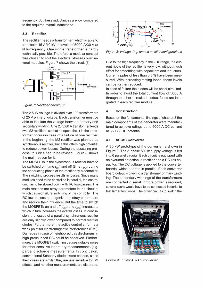
The 2.5 kV voltage is divided over 100 transformers of 25 V primary voltage. Each transformer must be able to insulate the voltage between primary and secondary winding. One 25 V/60 A transformer feeds two M2 rectifi ers, so that no open circuit in the trans-former occurs in case of a failure of one rectifi er. In the beginning, the M2 rectifi er was planned as synchronous rectifi er, since this off ers high potential to reduce power losses. During the upscaling pro-cess, this idea had to be revised. Figure 8 shows the main reason for it.The MOSFETs in the synchronous rectifi er have to be switched on (time tON) and off (time tOFF) during the conducting phase of the rectifi er by a controller. The switching process results in losses. Since many modules need to be controlled in parallel, the control unit has to be slowed down with RC low-passes. The main reasons are stray parameters in the circuits, which caused failure switching of the controller. The RC low-passes homogenize the stray parameters and reduce their infl uence. But the time to switch the MOSFETs on and off (tON) and tOFF) increases, which in turn increases the overall losses. In conclu-sion, the losses of a parallel synchronous rectifi er are only slightly lower compared to normal rectifi er diodes. Furthermore, the active controller forms a weak point for electromagnetic interferences (EMI). Damages in case of neighbored gas discharges in high-pressurized SF6 could be observed. Further-more, the MOSFET switching causes notable noise for other sensitive laboratory measurements (e.g. partial discharge measurement). In conclusion, conventional Schottky diodes were chosen, since their losses are similar, they are less sensitive to EMI eff ects, and no other measurements are disturbed.
Figure 7: Rectifi er circuit [3]
Figure 8: Voltage drop across rectifi er confi gurations
Due to the high frequency in the kHz range, the cur-rent ripple of the rectifi er is very low, without much eff ort for smoothing with capacitors and inductors. Current ripples of less than 0.5 % have been mea-sured. With increasing testing loops, these levels can be further reduced.In case of failure the diodes will be short-circuited. In order to avoid the total current fl ow of 5000 A through the short-circuited diodes, fuses are inte-grated in each rectifi er module.
4 Construction
Based on the fundamental fi ndings of chapter 3 the main components of the generator were manufac-tured to achieve ratings up to 5000 A DC current at 660 kV DC potential.
4.1 AC-AC Converter
A 30 kW prototype of the converter is shown in Figure 9. The 3-phase 50 Hz supply voltage is fed into 6 parallel circuits. Each circuit is equipped with an overload detection, a rectifi er and a DC link ca-pacitor. The DC voltage is applied to the converter boards, which operate in parallel. Each converter board output is given to a transformer primary wind-ing. The secondary windings of the transformers are connected in serial. If more power is required, several racks would have to be connected in serial to test larger test loops. The driver circuits to switch the
Figure 9: 30 kW AC-AC converter
41

Figure 10: 150 kV transmission path capacitor with inductance: internal capacitor stack (top left), internal inductor (top bottom), housing (right)
4.2 Capacitive transmission path
The internal and external assembly of one 150 kV capacitor is shown in Figure 10. Several of these capacitors are stacked for higher voltage levels.
The capacitors are mounted on insulating bars. The connections as well as the parallel resistors are soldered. In order to control the electrical fi eld at the sharp edges of the connection points, each con-nection point is shielded by a sphere. The assembly is mounted in hollow insulators, which are then fi lled with oil. This improves the dielectric strength as well as the thermal heat transfer. The toroidal coil is assembled below the capacitors. To insulate the resonant voltage of the inductor, the electrical potentials need to be insulated with insulating plates. The toroidal coil consists of several litz wire layers, which are twisted to achieve homogeneous current distributions among the layers.
4.3 Rectifi er
One individual rectifi er module as well as the con-nection of several parallel modules to form the 5000 A rectifi er are shown in Figure 11.
Figure 11: 100 A module (left) and 5000 A DC rec-tifi er (right)
Each module consists of four rectifi ers operating in parallel and provides a maximum current of 100 A. The transformer at the top provides the voltage for each M2 rectifi er. The rectifi er board is directly mounted on cooling devices. The rectifi er board output is connected to the plus and minus busbars of the module. The modules are connected in an array, which is connected to the main 5000 A plus and minus busbars. Additional electronics at the front of the rectifi er feed the auxiliary circuits, such as measuring devices or fans.
5 Commissioning
Each component has to successfully pass a com-missioning procedure. The commissioning of the overall assembly is still in progress.The AC-AC converter successfully generated its specifi ed power rating at ohmic loads. The tempera-ture rises of its components were much lower than the allowed limits. The capacitive transmission path was tested with 15 A at 50…60 kHz and 150 kV DC voltage. For this purpose, two capacitors as shown in Figure 10 were connected in parallel and short circuited at both top electrodes. High DC voltage was applied to the top electrodes, while the high frequency current fl ew through the loop from earth electrode one to earth electrode two. The compo-nents successfully withstood the stresses. Each 100 A module as well as the fi nal 5000 A rectifi er were successfully tested. The current distribution among the rectifi er modules was determined to be ±5 %.
MOSFETs are connected to the converter boards. All drivers are controlled by the same controller to ensure that the converters switch simultaneously. The input terminal is located at the top rack unit. The output of the rectifi er is a rectangular voltage, since this voltage shape is easy to achieve.
42

Further service experience must now be made with the components. Especially the long term perfor-mance is of interest, because the generator has to operate in long time cycles (e.g. continuously for one year). In the fi nal step the full assembly has to be built up to operate the generator at the specifi ed ratings of 5000 A and 660 kV.
6 Summary
In this contribution a new generator concept has been presented that is capable to inject a DC cur-rent of 5000 A at a high DC potential of 660 kV. The technical parameters have been given, together with some particular challenges during the design and construction phase. The main components of the generator have been explained in detail. So far, the generator concept seems to be techni-cally feasible.Assembly and commissioning of the fi nal 5000 A/ 660 kV generator is still in progress. Each individual component was tested successfully. Converter, transmission path and the 5000 A rectifi er are able to operate at the required technical ratings. Further experience, especially on long term performance, with the new generator concept and the generator design has to be gained and will be reported later.
Acknowledgments
The authors gratefully acknowledge support of this work by the IWB-EFRE-Program by the State of Hessen (Funding Code 20002558).
References
[1] C. Neumann et. al. “Some thoughts regarding prototype installation tests of gas-insulated HVDC systems” CIGRÉ Winnipeg 2017
[2] IEC 62895:2017 “High voltage direct current (HVDC) power transmission - Cables with ex-truded insulation and their accessories for rated voltages up to 320 kV for land applications - Test methods and requirements”
[3] M. Hallas, V. Hinrichsen “General overview of AC and DC current injection on high voltage potential for HVDC long-term tests” CIGRÉ Hakodate 2019
[4] M. Hallas, T. Wietoska, V. Hinrichsen “Genera-tor for Current Injection on High DC Potential to Test HVDC Equipment” ISH Buenos Aires 2017
[5] W. Schuff t, S. Schiering “Developmets in Power Engineering and their Demands on High-Volt-age Test Equipment” ELECO 1999.
[6] B. Yang, “Device for Testing Load of super-conducting High-Voltage DC Cable”, patent WO2014046467 A1.
[7] Vishay MKP1848C55012JK2 “Metallized Poly-propylene Film Capacitor” www.vishay.com accessed 09.02.2019
[8] Vishay MKP386M482250YT3 “Metallized Poly-propylene Film Capacitor” www.vishay.com accessed 09.02.2019
Zusammenfassung
Die DC-Stromeinprägung auf Hochspannungs-potential ermöglicht eine realitätsnahe Prüfung von HGÜ-Betriebsmitteln entsprechend ihrer späteren Betriebsbelastung. Mehrere Konzepte sind denk-bar. Ein modulares Konzept für hohe Strom- und Spannungswerte ist die kapazitive Stromeinprägung. Dieses besteht aus einer Versorgungseinheit, der kapazitiven Übertragungsstrecke und dem Gleich-richter auf Hochspannungspotential. Es wird ge-zeigt, wie die einzelnen Komponenten aufgebaut werden können und welche technischen Parameter im Generator notwendig sind. Das Ziel des Pro-jektes ist die Stromeinprägung von 5000 A DC auf ein Gleichspannungspotential von 660 kV DC. Die Herausforderungen und Lösungen während der Design-Phase des Generators werden dargestellt. Es werden Bilder der Generatorkomponenten sowie erste Erfahrungen mit dem hochskalierten Konzept vorgestellt. Zusammengefasst zeigt der Beitrag, dass das neue Generatorkonzept für die Einspeisung von Gleichstrom bei hohem Spannungspotential technisch realisierbar ist.
Author
Martin HallasTechnische Universität DarmstadtFachgebiet HochspannungstechnikFraunhoferstraße 464283 [email protected]
43