EPRI Project Final Report - The National HVDC Centre
29
1 Coordination of ac protection settings during energisation of ac grid from a VSC HVDC interconnector Aim of this report This report is aimed to provide an overview of the project conducted between EPRI and the UK National HVDC Centre. The report provides the main technical points covered in the project. Supplementary information in the form of PowerPoint slides are also available and provide more detail on the specific project steps, challenges, modelling and results. Project Partners List of Project Outputs Output Description Confidentiality Overview final report Public Project slides (supplementary material to this report) Public IET DPSP conference paper Public pre-print Protection Algorithm Review Confidential Detailed Project slides (supplementary material to this report) Confidential DigSILENT PowerFactory model with protection modelled Confidential RSCAD network model of restoration path Confidential Model Descriptor slide deck Confidential Abstract VSC HVDC can and has been used for black start and system restoration of ac power networks. The relatively low short circuit current limit of VSC converters in comparison to conventional synchronous generation can affect grid short circuit and dynamic characteristics during a black start. This can impair protection performance at both transmission and distribution levels. This project has assessed black start from VSC HVDC through a case study on the Scottish transmission grid. Through the project the AC protection implications of black start from HVDC were the
-
Upload
khangminh22 -
Category
Documents
-
view
5 -
download
0
Transcript of EPRI Project Final Report - The National HVDC Centre
1
Coordination of ac protection settings during energisation of ac grid from a VSC HVDC interconnector
Aim of this report This report is aimed to provide an overview of the project conducted between EPRI and the UK
National HVDC Centre. The report provides the main technical points covered in the project.
Supplementary information in the form of PowerPoint slides are also available and provide more
detail on the specific project steps, challenges, modelling and results.
Project Partners
List of Project Outputs Output Description Confidentiality
Overview final report Public
Project slides (supplementary material to this report) Public
IET DPSP conference paper Public pre-print
Protection Algorithm Review Confidential
Detailed Project slides (supplementary material to this report) Confidential
DigSILENT PowerFactory model with protection modelled Confidential
RSCAD network model of restoration path Confidential
Model Descriptor slide deck Confidential
Abstract VSC HVDC can and has been used for black start and system restoration of ac power networks.
The relatively low short circuit current limit of VSC converters in comparison to conventional
synchronous generation can affect grid short circuit and dynamic characteristics during a black
start. This can impair protection performance at both transmission and distribution levels. This
project has assessed black start from VSC HVDC through a case study on the Scottish transmission
grid. Through the project the AC protection implications of black start from HVDC were the

2
primary focus of the analysis. The following steps were taken in the project. The focus of this
report is primarily on the simulations performed in task 2.
1. Desktop review of algorithms of protection relays on the network
2. Simulations to perform restoration studies and assess protection coordination
a. Both hard and soft energisation of network from HVDC considered
b. Restoration with and without faults on the network
c. Response of relays to faults during soft energisation
d. Transformer inrush and load pickup
e. Re-synchronisation to the rest of the grid
3. Hardware testing of specific relays in the HVDC centre lab to triggered events.

3
Contents Aim of this report .......................................................................................................................................... 1
Project Partners ............................................................................................................................................ 1
List of Project Outputs .................................................................................................................................. 1
Abstract ......................................................................................................................................................... 1
Introduction .................................................................................................................................................. 4
Protection considerations when black-starting from VSC HVDC .............................................................. 5
VSC HVDC current limits ........................................................................................................................... 6
VSC HVDC negative sequence current characteristics .............................................................................. 6
Post-fault power recovery ........................................................................................................................ 7
Transformer inrush and line energisation ................................................................................................ 7
Application of soft energisation using VSC HVDC ................................................................................... 10
Re-connection of conventional power plants ......................................................................................... 10
Re-connection of Wind Power Plants, Solar PV, and Battery Energy Storage ........................................ 12
Synchronisation of black start islands and rebuilding grid to full integrity ............................................ 13
Case Study: Black Start of a portion of the Scottish grid from VSC-HVDC .................................................. 13
Transformer and Line Energisation Tests ............................................................................................... 14
Soft Energisation ..................................................................................................................................... 18
Response to Grid Faults .......................................................................................................................... 20
Inclusion of Synchronous Generation ..................................................................................................... 22
Resynchronisation to neighbouring grid ..................................................................................................... 24
Conclusions and Recommendations ........................................................................................................... 26
Acknowledgment ........................................................................................................................................ 27
References .................................................................................................................................................. 28

4
Introduction Decarbonisation of energy networks has meant conventional fossil fuel generation plants are being
retired and replaced with clean renewable generation. Traditionally, these fossil fuel plants were
key components in utilities’ black start and restoration plans. For example, black start plans often
involve the self-starting of black start units and energising paths to a nearby loads to construct a
power island, which is grown out towards other large fossil fuel plant which are used as additional
energy and voltage control sources for the supporting of continued restoration. Removal of the
fossil fuel generation sources means that the industry is looking to non-conventional sources for
black start and restoration planning. Energy resources like wind power, solar power, and battery
energy storage all have a role to play in future restoration plans and is an area of continued research
[1-3].
Interconnectors by their very nature tend to represent high capacity connections to a system, at or
up to the scale of the maximum loss level supported by that system’s frequency containment policy
and its availability and flexibility for cross-border trade is core to its market activity. An
interconnector utilising voltage source converter-based high voltage direct current (VSC HVDC)
has the capacity and the availability to become a valuable black start resource. The inherent
controllability of a VSC means that the HVDC control can be operated in island mode and provide
a stiff voltage and frequency on the ac side requiring black start. Early in restoration when much
active power flow may not be required, the VSC has the capability to act as a STATCOM providing
reactive support to the restoring grid supporting circuit re-energisation and subsequent voltage
containment. Later in restoration, the HVDC interconnector has a large active power resource to
support load pickup and synchronisation to other islands whilst continuing to regulate the voltage
and frequency of the power island which is in the process of being enlarged.
The very first commercial HVDC link between Sweden and the island Gotland had black start
capability. Since the HVDC system used line commutated converters, a synchronous condenser
was required to start-up the dc link on the Gotland side. Voltage source converters have simplified
the black start sequence from HVDC. VSC’s are self-commutated meaning they can operate at
zero power transfer and with the appropriate control, have the capability to energise the ac grid.
After the US North Eastern blackout of 2003 there was practical experience of utilising HVDC to
restore a system post blackout. The Cross-Sound Cable, a VSC HVDC interconnector between
New England and Long Island was used to energise portions of the Long Island grid [4].
There have been several black start tests using HVDC as the primary source, particularly using
interconnectors between asynchronous areas, where the likelihood of both sides of the HVDC
being blacked out is reduced. Black start tests on EWIC and Skagerrak 4 have been well
documented [5,6]. These tests have determined several unique issues with both protection and
operation of HVDC while restoring the ac grid. The major conclusion in both series of tests is the
importance of studying the problem in detailed electromagnetic transient studies to understand and
quantify the potential issues [7]. Furthermore, there is no substitution for field tests to determine
the suitability of a black start plan.
A consequence of retirements of synchronous plants is reduced inertia and fault levels. For a black
start condition using existing VSC HVDC systems, there is no inertia present at the beginning and

5
limited inertia through the early stages of restoration. Frequency management via rapid ramping
controls maintain the power island however given the lack of inertia voltage angles within the
power island may move dynamically as this is occurring. During a black start the ac system is also
reliant on the black start resources of the VSC HVDC to provide enough fault current to maintain
a stable restored grid. The short circuit current of a VSC is limited by its control system and
overload limits of the power electronic switches. This limit may affect grid short circuit and
dynamic characteristics during the energization of an ac grid from a VSC HVDC system; thus
impairing protection performance at both transmission and distribution levels.
In this paper a review of the potential protection issues during restoration from VSC HVDC is
presented in section 2. Section 3 outlines a case study energising a portion of the Scottish grid
from a future HVDC link and Section 4 provides some discussion and concludes the paper.
Protection considerations when black-starting from VSC HVDC Restoration of an ac grid from a voltage source converter presents several challenges regarding
grid operation and protection. Line differential protection, impedance protection, busbar
protection, breaker failure protection, overcurrent protection and transformer differential
protection schemes are potentially affected. In addition, there is potential maloperation of other
protection functions such as directional polarisation, frequency measurement algorithms, memory
voltage, power swing detection, or phasor frequency tracking and compensation. In such cases, the
sensitivity and reliability of the protection schemes could be degraded, which may pose dangers
to public safety and grid assets as well as prevent or delay system restoration.
• Impact of VSC HVDC current limit on protection sensitivity
• Impact of VSC HVDC suppression of negative sequence currents during unbalanced faults
on protection sensitivity, polarisation, and coordination
• Fast dynamics within VSC island and the impact on protection relay polarisation and
impedance phasor calculations
• Post-fault power recovery impact on voltage and frequency
• Risk of transformer inrush and line energisation exciting harmonic resonance and
controller harmonic instability
• Application of soft energisation using VSC HVDC and coordinating with voltage
protection
• Re-connection of conventional power plants
• Re-connection of wind/solar/batteries including short circuit ratio requirements and
voltage/frequency ride-through of wind, solar PV, and batteries
• Frequency stability impacts of operating reserve and load variability and uncertainty
• Synchronisation of black start islands and rebuilding grid to full integrity

6
VSC HVDC current limits Power electronics used for megawatt-class inverters tend to have very low, if any, overload
capacity. They are typically designed to ensure that they can deliver full rated power over normal
operating voltage range. This results in typical current limits of the order 1.1-1.2pu [8]. The exact
response of the VSC to short circuits depends on the real and reactive power control mode with
dynamic reactive power response being common in Europe [9,10]. This contrasts with
synchronous generators which can typically provide short circuit currents of the order 5-7pu
current [8].
Protection devices which operate using current measurements such as overcurrent, impedance, and
unit protection relays typically include a minimum operating current setting. This is often
configured based on factors such as minimum current transformer accuracy (e.g. 5-10% of CT
continuous rated current), some percentage of the protected device’s rated load (e.g. 120% of
busbar rated current), or some percentage of minimum fault level (e.g. 80% of short circuit current
under N-1 or G-1 contingency). The reduced short circuit current magnitudes during system
restoration could compromise the ability of these protection devices to detect faults. This is
particularly the case if the minimum operating current is configured based on device rated current
or a high percentage of minimum short circuit current.
VSC HVDC negative sequence current characteristics With the exception of Germany [11], few other grid entities have created requirements for VSC-
interfaced energy sources to provide negative sequence current during unbalanced grid conditions
such as single or two-phase faults. It has been common practice for VSC HVDC to incorporate
negative sequence current control loops to damp out negative sequence components as these can
give rise to even harmonic distortion and overvoltages on the dc side [12].
The VSC controller time-constants typically result in the negative sequence current being
suppressed within 40-100 ms. This sees the negative sequence current rising immediately after the
fault occurs, before the controllers begin to respond and act to reduce it. During single-phase to
ground faults it is a common assumption that the negative sequence current is equal in magnitude
to the positive sequence current, but opposite in phase angle. With an inverter with a negative
sequence controller, however, the phase angle will change in time. The exact magnitude and speed
of that change depends on the controller parameters. One of the benefits of defining a requirement
for negative sequence current response is that the effort required for modelling, simulation and
protection assessment is significantly reduced. Phasor domain short circuit tools can be used for
initial screening and coordination studies, while more advanced time-domain analysis using RTDS
or EMT simulations can focus on investigating specific issues.
The impact of the absence or much-reduced presence of negative sequence current is different
depending on the protection function, the relay manufacturer’s algorithms, and the settings applied
[8]. For this reason, it was considered important to use relay-specific models in simulations as well
as performing lab-testing of the relay hardware. At a high level, the main impact is on directional
polarisation functions, negative sequence overcurrent, and negative sequence unit protection [13].

7
Negative sequence overcurrent and unit protection are relatively rarely used outside of North
America. As there tends to be at least some negative sequence current in the initial cycles after
fault initiation, Zone 1 distance protection and similar fast-tripping elements are relatively
unaffected once the short circuit current magnitude exceeds the relay’s minimum operating
current.
Post-fault power recovery A feature of the August 2019 demand disconnection event in Great Britain was an unexpected
post-fault power recovery behaviour from 800 MW Hornsea wind farm. This recovery resulted in
a transient under-voltage which led to wind turbine overcurrent protection tripping. The reactive
power swing was due to a change in collector network impedance associated with outages on the
collector network at the time [14]. Similar issues could potentially exist with VSC HVDC during
system restoration, but a thorough simulation and analysis at the design stage combined with
appropriate compliance testing in the factory, at commissioning and through life should avoid such
behaviour.
Transformer inrush and line energisation Transformer energisation usually results in severely distorted inrush current with high 2nd
harmonic content due to the non-linear flux-current characteristics of the iron core. Under normal
grid operating conditions with a strong source, the initial magnitude of the inrush current can be
up to seven times the transformer rated current with an exponentially decaying characteristic [15].
The exact magnitude and shape of the inrush current depends on the core characteristics and
remnant flux in the transformer core. This is a function of the point on-the voltage waveform at
which each circuit breaker opened when the transformer was last switched out, and the point on
the voltage waveform at which each of the three circuit breakers close to re-energise the
transformer. The most severe inrush current typically decays within the first hundred milliseconds.
This distorted inrush current still exists when transformers are energised from a VSC HVDC,
although the VSC can only supply limited magnitude of current and remain stable for limited
magnitude of harmonic distortion.
Unit protection uses current transformers on the windings with external connections to detect faults
inside this protected zone. Unit protection provides fast-acting and reliable protection for internal
faults, but sensitivity is limited to the minimum operating current setting. The sensitivity is
ultimately limited by the accuracy range of the current transformers (typically accurate down to 5-
10% of rated current) and by current measurement errors arising when the transformer is operated
at an off-nominal tap position.
Protection settings philosophy also affects sensitivity. For example, some companies configure the
minimum operating current to be above transformer rated load current or some high percentage of
the minimum short circuit level. Such an approach reduces the risk of protection maloperation
should some failure occur in the CT secondary wiring or relay measurement input or processing
occur; if the measurement chain is interrupted on one or more phases the unit protection would not
see the current on one side of the transformer being balanced by currents on the other side. This
has resulted in protection maloperation in the past, but most events were primarily associated with

8
older electromechanical or static protection relays. Modern numerical protection devices have
measurement error detection functions to reduce the risk of such a maloperation.
If the unit protection is configured such that the minimum operating current is above the available
short circuit current from the HVDC converter, then it will not be able to detect all fault types
resulting in uncoordinated protection tripping at best and uncleared or very slowly cleared faults
and increased transformer damage at worst. This risk can be mitigated by adopting lower minimum
operating currents on the restoration path or developing a second settings group on the relay which
may be activated during system restoration, although using multiple settings group is often not a
preferred choice due to the increase in relay configuration complexity and requirement for human
intervention to activate them.
Where current transformers are only applied at the high side of each winding there exists some
potential issues exist around transformer inrush detection. Where both windings of a double-
wound transformer are wye-connected it is common to employ a medium-voltage, delta-connected
tertiary winding to provide a path for flux during transformer energisation. Without the delta-
connected winding the flux would inductively couple to nearby ferrous material such as the
transformer shell resulting in spot-heating and severe vibrations. It is uncommon for current
transformers to be installed on this delta winding, so unit protection will only measure current on
the energising winding, but not the delta winding, and potentially trip. This is prevented using
inrush detection logic which dynamically blocks unit protection during transformer energisation.
A common approach to implementing this feature is to block differential function if 2nd harmonic
current exceeds a set percentage of fundamental frequency current. Default settings vary between
manufacturers, but a value of 15% is common. An inrush protection study may be necessary to
ensure that the relay settings and configuration are appropriate. For example, how cross-blocking
should be configured. Cross-blocking is a common protection feature where inrush current
detection on one or more phases automatically triggers the relay to block tripping should excessive
differential current be detected on the other phases. If cross-blocking is enabled, the differential
protection is more secure – inrush current tends to be unbalanced and the harmonic distortion on
one phase could exceed 15% of fundamental, but not on the others. However, enabling cross-
blocking could also result in the relay blocking tripping when the transformer is energised onto a
faulted condition or a flashover occurs immediately after energisation. The reduced inrush current
magnitude which can exist when the transformer is energised from a remote HVDC converter may
not guarantee that these functions will perform securely and reliably. As such, specific simulations
should be performed to assess protection performance and to identify the optimal configuration or
inrush detection and cross-blocking logic.
For the grid studied as part of this work the transformers on the restoration path are Yyd auto-
transformers arranged as three single-phase banks with current transformers on high and neutral
side of each single-phase winding. As the unit protection can measure the current entering and
exiting each winding the protection scheme inherently discriminates inrush current from fault
current.

9
As inrush current can reach similar magnitudes to short circuit current, overcurrent and impedance
protection can be similarly exposed to incorrect tripping during transformer energisation. Again,
inrush detection functions are employed to prevent incorrect protection operation. Inrush detection
is not always applied or available on line protection relays; this is not usually an issue as
transformers are usually energised from an intact network and so the inrush current is sourced from
multiple lines and no one relay experiences a significant increase in current.
During system restoration, however, there is only one path between black start unit and transformer
in which case the protection on this path will see the entirety of the inrush current. This could
present a risk of maloperation depending on the impedance protection reach and time-delay
settings. This is particularly the case when switch-on-to-fault (SOTF) protection. Such protection
temporarily activates very sensitive or fast-tripping zones for a short period after the line is
energised. This enables the protection to quickly trip in response to faults present at the time of
energisation such as line earths left connected after maintenance.
A number of methods are available in modern relays for detecting line energisation. While it is an
obvious choice, circuit breaker status is not always a reliable method of detecting line status as the
time delay between breaker closing and circuit breaker status auxiliary contacts closing to signal
the protection relays could be too slow to achieve fast SOTF tripping. For this reason, internal
relay logic is often used which uses the detection of a sudden increase in current and/or voltage
above certain critical values to signify a change in line status. This logic uses the absence of voltage
and current (for example voltage falling below 50% of nominal and current falling below 10% of
rated current) to determine that the circuit has been de-energised. When the voltage or current rise
above these values the line is assumed to be energized again and the SOTF protection function is
enabled.
If SOTF is based on current only, then the inrush current could be interpreted as SOTF which
could release an overcurrent element causing the relay to trip. Current-only SOTF is used in order
to detect three-phase faults, where voltage may not be present. If the relays provide the capability
to choose voltage or current to detect line energisation, then the presence of voltage during line
energisation will be sufficient to deactivate SOTF prior to the switching for energising the
transformer. If not, then the SOTF impedance or overcurrent protection should be studied to
determine if it would be secure during such inrush events.
Should the line or transformer energisation excite a resonance in the grid a significant flow of
harmonic current could flow on the circuit, while the voltage distortion could de-stabilise the
HVDC controllers. Grid protection system may or may not respond to resonance conditions. Most
numerical protection devices will filter out harmonic distortion, so unless the fundamental
frequency currents or measured impedance reach abnormal levels they may not respond. The
HVDC controller may recognise that an abnormal condition has been reached or have specific
control or protection designs to detect the resonance.

10
Application of soft energisation using VSC HVDC Soft energisation can be used to energise transmission circuits and one or more unloaded
transformers by slowly ramping the voltage from 0 to rated voltage. The main benefit of this
approach is that the slow ramp avoids the sudden changes in voltage which excite transformer
inrush and hence it is almost non-existent. It is primarily used with small synchronous generators
during black start where these units would otherwise lose stability and trip when nearby
transformers are energised It has also been used during system restoration tests in the past using
VSC HVDC [7].
The speed with which the voltage is ramped should be slow enough to mitigate the risk of
transformer inrush current exciting a resonance, while being fast enough to ensure that faults can
be detected and isolated quickly without causing damage or endangering safety. A 2014 network
restoration study by DNV GL examined the feasibility of soft energising a network in the
Netherlands with a synchronous machine. They concluded that any network may be energised with
soft energisation as it causes no transient phenomena. However, they also strongly recommend
transformer demagnetisation before energising to the rated voltage [18]. Some consideration
should also be given to the impact on auxiliary power supplies and connected equipment.
Where under-voltage protection is deployed within the grid being energised – for example on the
grid side of the HVDC converter transformer – the ramp must be fast enough to avoid this under-
voltage protection from tripping. Alternatively, the under-voltage protection could be temporarily
disabled during soft energisation, although this may not be practical or preferable in some
applications.
During soft energisation the VSC follows a ramp in its voltage setpoint. The reactive power output
responds to the setpoint and regulates the terminal voltage. If a fault is present, the reactive power
(and hence fault current) will depend on the voltage setpoint and the impedance between the VSC
and fault. At the start of the voltage ramp the fault current could thus be very low and likely to be
below the grid protection minimum operating current. The fault clearance time will thus depend
on the fault location and ramp rate. If the ramp takes place over tens of seconds or minutes, this
could lead to long fault clearance times. Wide-area monitoring could enable operators to identify
abnormal conditions during the early phase of ramping when the short circuit current is very low;
this may warrant specific investigation to determine if the fault currents – however low – could
cause excessive damage with such long durations.
Once the protection trips and isolates the fault, the voltage will immediately recover. If there are
any transformers nearby, this jump in voltage will give rise to inrush current, which could excite
the resonance which soft energisation was intended to help avoid. This effect may limit the extent
of network which can be soft-energised.
Re-connection of conventional power plants The process for re-synchronising generators to the black start island will depend on their operating
state:

11
• If the unit was not running prior to the blackout and is cold, then the auxiliary load will
need to be re-energised before then the generator goes through its start-up procedure. This
process can be very slow (hours) before it reaches rated output due to limits in heat-rates.
• If the unit tripped and shut down, then their auxiliary load will still need to be re-supplied,
but the plant can usually spin up, re-synchronise, and reach rated output much faster
• If the unit tripped to house load during the blackout event and is still spinning, then it can
be quickly re-synchronised to the grid
As a rule of thumb thermal generator auxiliary load – pumps, compressors, chillers etc - tend to be
in the range of 5-10% of rated generator output. If the generator has not tripped to house load and
spinning, then this auxiliary load will need to be energised. The motor starting current associated
with individual auxiliary load components can, in some cases, raise issues like the motors tripping
if a weak or far remote conventional black start unit is used. With VSC-HVDC, however, there
should not be, in general, any issues due to its relative size and robust controller design.
After the HVDC link energises the path to a power plant and, if necessary, the auxiliary load is re-
supplied and generator accelerated to rated speed, the generator circuit breaker (or grid-side
breaker) can be closed to re-synchronise the unit to the grid. With the typical settings employed
on synchronising relays there will be a slight mismatch in grid and generator frequencies when the
breaker is closed. This will result in power swings due to the transfer in energy as from the high-
frequency side to the lower-frequency side until they stabilise. In strong grids these power swings
are usually relatively small in magnitude and well damped. During system restoration, however,
they may be unstable or poorly damped if the generator is electrically remote from both HVDC
and load. Where studies identify potential issues the connection of nearby load prior to re-
synchronisation can provide a damping effect.
Once the synchronous generators connect to the black start island the grid short circuit current
level will increase; in general, this increase in fault level and inertia should reduce the risk of slow
protection operation and maloperation. If the synchronous generator should trip, however, the
HVDC will automatically regulate voltage and frequency by providing additional real and reactive
power. As this response can be very fast it can result in large magnitude rate of change of frequency
– the frequency initially drops due to the generator tripping, but the HVDC will respond within a
period of hundreds of milliseconds to seconds to regulate frequency. Thus the frequency could fall
and recover exceptionally quickly – an issue observed with other HVDC systems deployed around
the world.
Tuning the controller for a faster response risks making it less stable; this could potentially result
in wild swings in power in response to benign disturbances like load energisation and faults. A
slower response risks loss of frequency stability and under-frequency tripping. This is an issue
which is usually tackled as part of the HVDC controller design process, but may be specifically
important to consider with respect to loss of mains protection on distribution-connected generation
within the resupplied distribution grids.

12
Re-connection of Wind Power Plants, Solar PV, and Battery Energy Storage To re-connect inverter-interfaced resources such as wind or solar power plants certain technical
requirements must be met. Among these one of the most important is the short circuit ratio. The
short circuit ratio is a simple screening metric to help identify inverter-interfaced energy sources
which are at risk of small-signal instability. The metric masks much of the complexity of the
underlying phenomena including inverter controller design, inverter control interaction, and grid
impedance. To improve the reliability of the metric in identifying potential instability, a number
of refinements have been proposed including those by CIGRE, GE, EPRI, ERCOT and others. The
metric aims to capture the capacity of nearby power sources to respond to voltage and frequency
disturbances.
Almost all commercial inverter-interfaced power plants operate in grid-following mode and thus
need a relatively strong grid in order to ensure they provide stable response to grid disturbances
[3]. The required minimum short circuit ratio is often in the range of 3 to 5, but many wind and
solar plants have been operated down to 1.5 with appropriate changes to the inverter control design
and tuning. If this requirement is not met, the inverters may lose stability – resulting in severe
oscillations in real and reactive power output – or loss of synchronism with the grid resulting in
power swings and tripping of the inverters and, potentially, grid protection. Despite the HVDC’s
capability to tightly regulate voltage and frequency, at electrically remote distances this may not
prevent inverters from losing stability.
This may limit the number of inverter-interfaced power plants which can be re-connected during
the early stages of system restoration, but, for those which are viable for reconnection the short
circuit current ratio requirement should also ensure that the minimum operating current is exceeded
for protection relays along the restoration path.
Connection of variable energy sources or load with embedded generation can result in the loading
measured at transmission grid level fluctuating. Where significant penetration of embedded
generation exists across a grid this may result in correlated fluctuations in load across the island.
The VSC-HVDC’s frequency and voltage control and reserve strategies should allow for this
variability and uncertainty in order to prevent frequency and voltage regulation issues. Insufficient
real and reactive power reserve could result in voltage or frequency excursions and, potentially,
tripping of embedded generation.
Where transmission-connected wind and solar plants can be controlled, it may be prudent to review
the forecast over the restoration timeframe. Variability and uncertainty in output could thus be
reduced by dispatching them to a power level below the minimum forecast output. Error!
Reference source not found. illustrates an example, where the red line is the time the power plant
is connected to the black start island and the green line shows the dispatch over the restoration
period.

13
Figure 1: Example dispatch of wind power plant to reduce frequency reserve requirements during restoration
Synchronisation of black start islands and rebuilding grid to full integrity Once two or more black start islands have been established and the path to their synchronising
substation energised the islands are ready to be re-synchronised. Assuming the VSC HVDC is still
in island control mode, it should remain in this mode until after the grids have been synchronised.
When re-synchronising black start islands any frequency or phase angle difference may result in
power swings between the two grids. It is possible in future restoration across two power islands
that these two islands could be entirely or mainly supported by VSC HVDC convertors in island
control mode. Careful analysis of these power swings is important as they can cause impedance
relay tripping. power swing blocking can mitigate this tripping, however it is not employed on the
GB grid [16]. Further analysis of converter control strategies involved in such re-connections is
also appropriate to avoid excessive interaction.
Case Study: Black Start of a portion of the Scottish grid from VSC-HVDC In black start scenarios the aim is to expand power islands quickly and safely to pick up more
generation and load. This study investigates restoration of a portion of the Scottish ac transmission
network. The 400 kV ac network is energized from a generic model intended to represent a future
1,400 MW VSC HVDC interconnector with black start control. Figure 2 displays a representative
diagram of the HVDC connected to the restoration path. The restoration plan is to pick up the ac
network from the HVDC and expand the power island to synchronise with a synchronous
generator. This case will examine transformer energisation, line energisation, soft start of the
HVDC and short circuit faults. The modular multilevel HVDC model has been used with generic
control parameters and is operated in island control mode during the restoration. Further details on
island mode control can be found in [17]. The network is modelled in DIgSILENT PowerFactory
with simulations carried out using the electromagnetic transients (EMT) mode.
14
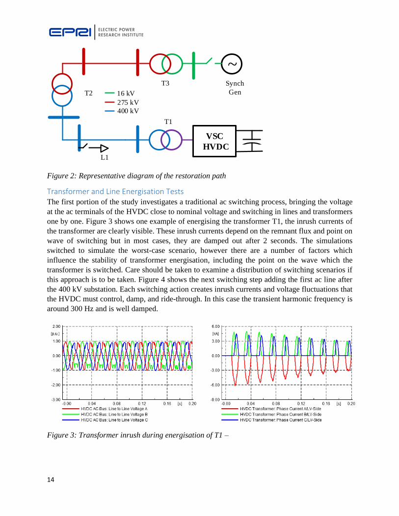
Figure 2: Representative diagram of the restoration path
Transformer and Line Energisation Tests The first portion of the study investigates a traditional ac switching process, bringing the voltage
at the ac terminals of the HVDC close to nominal voltage and switching in lines and transformers
one by one. Figure 3 shows one example of energising the transformer T1, the inrush currents of
the transformer are clearly visible. These inrush currents depend on the remnant flux and point on
wave of switching but in most cases, they are damped out after 2 seconds. The simulations
switched to simulate the worst-case scenario, however there are a number of factors which
influence the stability of transformer energisation, including the point on the wave which the
transformer is switched. Care should be taken to examine a distribution of switching scenarios if
this approach is to be taken. Figure 4 shows the next switching step adding the first ac line after
the 400 kV substation. Each switching action creates inrush currents and voltage fluctuations that
the HVDC must control, damp, and ride-through. In this case the transient harmonic frequency is
around 300 Hz and is well damped.
Figure 3: Transformer inrush during energisation of T1 –
VSC
HVDC
~
T1
T2
T3 Synch
Gen16 kV
275 kV
400 kV
L1
15
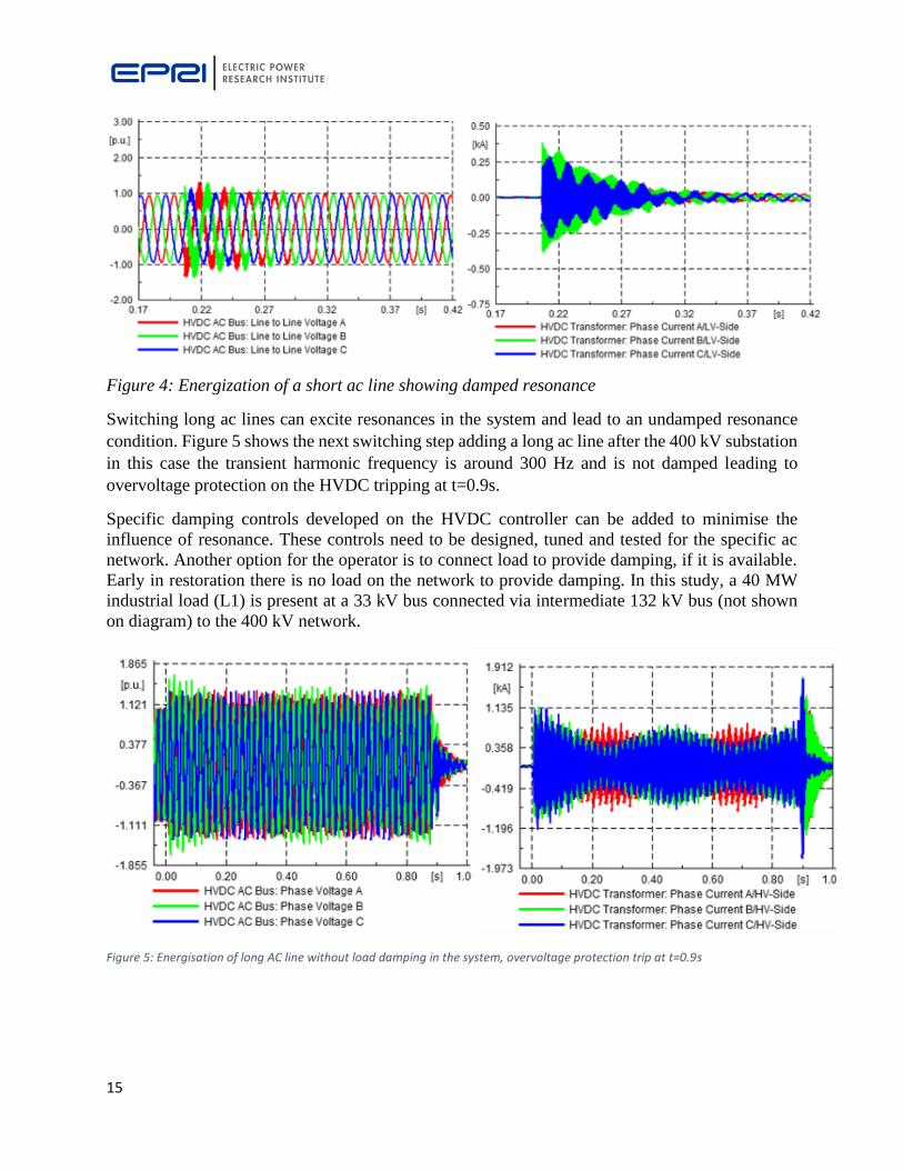
Figure 4: Energization of a short ac line showing damped resonance
Switching long ac lines can excite resonances in the system and lead to an undamped resonance
condition. Figure 5 shows the next switching step adding a long ac line after the 400 kV substation
in this case the transient harmonic frequency is around 300 Hz and is not damped leading to
overvoltage protection on the HVDC tripping at t=0.9s.
Specific damping controls developed on the HVDC controller can be added to minimise the
influence of resonance. These controls need to be designed, tuned and tested for the specific ac
network. Another option for the operator is to connect load to provide damping, if it is available.
Early in restoration there is no load on the network to provide damping. In this study, a 40 MW
industrial load (L1) is present at a 33 kV bus connected via intermediate 132 kV bus (not shown
on diagram) to the 400 kV network.
Figure 5: Energisation of long AC line without load damping in the system, overvoltage protection trip at t=0.9s

16
Figure 6: Energisation of long AC line without load damping in the system, overvoltage protection trip at t=0.47s
NOTE: The difference between Figure 5 and Figure 6 is the addition of the 150 Mvar shunt
reactor at the end of the long AC line. Figure 7 shows this difference in the active and reactive
power plots where the different resonant frequencies can be clearly seen.
Figure 7: Difference between oscillations in power for undamped resonance comparing simulation without shunt reactor switched in to with phase reactor switched in.

17
Figure 8: Energising a long 400 kV ac line with load providing damping.
Figure 8 shows the energisation of the same long ac line as Figure 7. Energising the load provides
sufficient damping to continue energising ac lines and transformers along the restoration path. It
is worth noting that the operator may not have available load to switch in and provide damping. In
these scenarios the operator may rely on specific controls developed on the HVDC to damp
resonances.
Figure 9 shows the energisation of a 400/275 kV 1000 MVA transformer. The switching action
causes inrush currents which excite a resonant condition in the network causing a temporary
overvoltage; the HVDC over-voltage protection operates to de-energise the grid. In a system
restoration situation this would necessitate the restoration path being energised once again. The
connection of load into the network provided sufficient damping to prevent these overvoltages.
Figure 10 shows the impedance zones and trajectory seen by the impedance protection relay on
the 400 kV line supplying the transformer as an example of one of these simulations. Despite the
magnitude of the inrush current the impedance does not enter any of the tripping zones.
Figure 9: 400/275 kV transformer 3 phase voltage and current showing inrush exciting a
resonant condition

18
Figure 10: impedance zones and trajectory seen by the impedance protection relay on the 400
kV line
Using VSC HVDC to energise a network component-by-component in the traditional manner is
practical for this case study, but care is needed in ensuring sufficient load is connected or that
sufficient HVDC damping controls are available and tested to mitigate resonances that can be
excited by transformer inrush or line energisation. Addition of other equipment such as small
synchronous generators, synchronous condensers, SVC’s, STATCOMs, batteries etc. to the
restoration network were not considered in this case but could also aid restoration in terms of
provision of active and reactive power and the ability to provide damping of overvoltages.
Soft Energisation An advantage of using HVDC for black start is a granular control of voltage across a wide range
of timeframes and magnitude and therefore the ability to soft start the network via a defined
strategy of voltage ramping by the VSC-HVDC. With this approach multiple lines and
transformers are energised in a single pass with the HVDC terminal voltage ramped from zero to
rated voltage over a period of seconds to minutes. This can much more rapidly re-energise the
network area that the HVDC is capable for supporting load for, ahead of re-energising that load.
The ac breakers on the entire restoration path are closed (the load is disconnected) and the voltage
is ramped up slowly. Figure 11 shows the voltage, current, active and reactive powers at the HVDC
terminals following the soft start ramp over a period of 2 seconds. Transients and transformer
inrush currents are much reduced, and no unstable resonance is observed. This soft energisation
can only be used once in the black start strategy to build up the initial network, subsequent stages
must then follow a traditional path as previously outlined. In any soft start energisation there is a
risk of a latent fault existing which may have resulted from the conditions leading up to the black

19
start or actions in response to it. As such it is important that this strategy is also tested for robustness
to energisation onto a latent network fault.
The soft energisation sequence was repeated in Figure 12, but with single and three-phase faults
at different locations in the grid. It was observed that it took approximately 0.2 s in the worst case
for current to reach the unit protection minimum operating current and the relays to trip; however,
after the circuit breakers tripped and isolated the faulted line, the voltage on the healthy part of the
grid recovered rapidly.
Figure 11: HVDC Voltage, active and reactive power during soft start of restoration path
This step-change in voltage had a similar effect on nearby transformers as a regular energisation
and so significant inrush current flowed and again excited a harmonic resonance. This experience
would suggest that soft-energisation should be used with caution where the risk of faults on the
grid is abnormally high, or that specific control strategies on the VSC should be introduced to limit
the risk of such resonances. It is also important to note that the protections in place on the re-
energised circuits during this soft energisation may not respond to the fault condition and as such
the operator may need to discover the fault via repetitive attempts at soft energising more limited
network areas, or reverting to traditional approaches after a failed attempt.

20
Figure 12: Voltage and current during soft-start of restoration path with permanent 3-phase
fault
Response to Grid Faults Protection systems along the restoration path were modelled with manufacturer-specific models
and parameterised using site-specific data. The relays included electromechanical, static, and
numerical devices. After performing a coordination study of impedance protection relays EMT
simulations were performed to examine the response of the relays considering the HVDC
controller characteristics and dynamic behaviour. Due to the power rating of the HVDC and tap-
position of the grid-transformer there was a maximum of 2.3 kA available for close-in faults on
the 400 kV grid.
With current transformer ratios of 2000/1A and minimum operating currents in the range of 0.1-
0.2pu the HVDC was found to be capable of supplying sufficient short circuit current for protection
to quickly isolate low-impedance faults all the way to the synchronous generator. The use of auto-
transformers with grounded neutral connections also ensured sufficient zero sequence current for
ground fault elements to operate. No protection relays on the path used negative sequence
overcurrent, negative sequence unit protection, or negative sequence directional polarisation and
so the absence of negative sequence current from the VSC had limited impact compared to the
other issues discussed. The hardware in the loop testing using relays and controller replica may
identify potential issues, but this could be a time-consuming effort. If the negative sequence current
response is defined – such as that practiced in Germany – can significantly reduce the analysis
effort as generic HVDC models and protection coordination tools can be used for the study instead
of black-box vendor models and sophisticated RTDS or EMT tools.

21
Figure 13: Relay characteristic and impedance on 400 kV line
Figure 13 shows the impedance relay characteristics and the relay calculated impedance for a three-
phase fault at 95% along a 400 kV line on the restoration path, when the voltage along the path
has been fully restored. The relay can be seen to correctly detect the fault in Zone 2 under normal
conditions.
Considering grid faults during soft energisation is an important part of this analysis. A three phase
fault is applied on the same 400 kV line, approximately 200km from the HVDC. The VSC HVDC
is configured to soft-energise by ramping to 1pu voltage over 2 seconds. The fault current increases
from 0 to 400A, which is the unit protection minimum operating current before the unit protection
trips.
After the breaker opens, a sudden voltage recovery can be seen as the HVDC output voltage has
continued to ramp during the fault, so the post fault voltage is higher than the pre-fault voltage.
This has the effect of mimicking the effects of a hard energisation. The sudden voltage recovery
in this case excites inrush currents on a nearby transformer and excites the resonance at the 6th
harmonic, identified during hard energisation simulations.

22
Figure 14 (L) Fault current increases from 0 to 400A (unit protection minimum operating current) and
then trips, (R) Sudden voltage recovery after breaker opens excites inrush and a resonance
Inclusion of Synchronous Generation Once the restoration path has been fully energised, the synchronous generators at the end of the
restoration path can be synchronised. Simulations showed successful synchronisation of the
generators as expected. Figure 15 shows the system topology for the following tests.
Figure 15: Schematic of system layout after synchronous generator connected
VSC
HVDC
~
T1
T2
T3 Synch
Gen16 kV
275 kV
400 kV
L1

23
The VSC will adjust its frequency according to its control settings up to its available real power
limit. The inner current control defines the initial response of the VSC (in the ms time frame) and the
outer frequency control defines the setpoints for the inner control to reach, within the current limits.
The inner current control can be tuned to be less responsive to events such as the tripping of a
synchronous generator. The response also depends on the network configuration, during black start
there is a weaker network configuration than normal operation. In this study the controls have not
been tuned to respond optimally to an event during black start. The most likely outcome is that the
VSC will have a "black start setting" where the control is tuned to cover events during black start
scenarios defined in pre specification studies.
Simulations were performed to study the response of the system to the tripping of synchronous
generators in the black start island. Figure 16 shows the frequency response and rate of change of
frequency following the tripping of 220 MW of hydropower generation when approximately 300
MW of load has been picked up. The response of the VSC HVDC occurs within cycles of the
tripping, but this also results in a correspondingly high ROCOF which could lead to disconnection
of distribution-connected generation by loss-of-mains protection.
Figure 16: Frequency, Rate of change of frequency and Active & Reactive power response of
HVDC during loss of synchronous generation

24
Resynchronisation to neighbouring grid Once the first restoration island has been restored, the next step is to begin resynchronisation to
the neighbouring grid. The neighbouring grid in this studied scenario is a high inertia grid to the
south of the restored path. Synchronisation was tested at 400 kV substations near the HVDC and
at another 400/275 kV station farther from the HVDC and relatively close to the synchronous
generator. No issues were observed when synchronising the restored grid to the larger grid at a
400 kV bus near to the HVDC terminals. Synchronisation was tested with different phase angle
differences: 0, +/-15, +/-45. Table 1 summarises the results of the resynchronisation simulations
and Figure 17 shows a sample result for a case where the synchronisation point is far from the
HVDC and the synchronous generator is connected.
Table 1: Summary of re-synchronisation simulations
Connection Point Synchronous
Generator
Connected?
Comments
Near HVDC N Synchronisation stable
Near HVDC Y Synchronisation stable
Far from HVDC N Synchronisation stable
Far from HVDC Y Synchronisation stable - Some
transients observed and can potentially
become unstable if the phase angle
difference is large and the re-
synchronisation point is far from the
HVDC.
Having Load connected near
synchronous generator prior to re-
synchronisation improves stability and
damping.
Figure 17: Re-synchronization with England: -45 degree phase diff as example – further results in slides.

25
Hardware in the Loop Testing While the simulated performance of the protection systems was useful in identifying potential issues,
the models do not contain proprietary signal processing or functional logic. In order to more fully
investigate the relay performance several protection relays were tested in hardware-in-the-loop (HIL)
with the RTDS. Error! Reference source not found. shows three of the protection relays – Alstom P441,
GE D90, and Siemens 7SD6 as well as a Doble F6185 power system amplifiers. The hardware in the loop
test setup has tested and implemented and is ready for further investigation in the HVDC Centre lab.
Figure 18: Protection Relays and Power Amplifiers setup for the Hardware in the Loop Testing

26
Conclusions and Recommendations Black start and system restoration from VSC HVDC have been proven in live grid tests and real
system restoration events. The short circuit current characteristics and control system behaviour
can have specific impact on grid protection devices. Reduced short circuit current magnitude and
reduced negative sequence current magnitude from inverter interfaces can affect the ability of
protection devices to detect faults and correctly determine fault direction during the early stages
of system restoration. Potential mal-operation of protection during low inertia black start and
restoration scenarios are discussed and examined. Soft energisation from VSC HVDC is assessed
to mitigate the risk of transformer inrush current exciting harmonic resonance. The following
conclusions and recommendations can be drawn from this work:
• Using the soft start capability from HVDC for black start provides a significant advantage
in terms of restoring the grid. Care must be taken to properly study all restoration paths and
ensure protection is adequately set up for new restoration procedures.
• During hard energisation there is a risk of exciting resonances.
• During soft energisation, under voltage detection on relays will need to be blocked during
the slow controlled ramp of voltage.
• . AC fault detection on the HVDC control system will need to be designed to detect faults
during soft start and all points of restoration, due to the different network topology during
restoration compared to normal operation.
• Delayed fault clearance is likely if faults occur during soft energisation.
• With soft energisation, the greatest risk is energising onto an existing fault.
• There is a risk of exciting resonance due to fast post-fault voltage recovery if faults occur
during soft energisation.
• At rated voltage VSC HVDC provided enough current for fault detection/relay operation
in the simulation tests.
• During restoration, strategic reconnection of load is advantageous to maximise grid
stability.
• Re-synchronisation of the “restored” AC grid fed by the HVDC to the rest of the AC grid
has been assessed and few issues were recorded, however, further work should examine
re-synchronisation to other islands under different scenarios and at different connection
points. Such analysis was beyond the scope of this project.
• Post initial restoration the HVDC will be in black start control mode, determining the
appropriate conditions and point where the HVDC should return to normal operating mode
is a topic where further R&D should focus.
• On the restoration path under study, there is little synchronous generation present,
therefore, connection of wind farms or other inverter interfaced resources is the next step.
Since there is little synchronous generation, there will be low fault current levels and low
inertia levels which may complicate the connection of these wind farms.

27
Acknowledgment EPRI would like to acknowledge support for this research, funded through the Ofgem Network
Innovation Competition project titled ‘Multi-Terminal Test Environment (MTTE) for HVDC
Systems’. EPRI would also like to acknowledge the support of the National HVDC Centre, SP
Energy Networks, SSE and National Grid ESO for their support and advice during this project.

28
References [1] National Grid ESO, “Distributed ReStart, Project progress report – Bi-annual, January – June
2019” Online: https://www.nationalgrideso.com/document/147516/download
[2] M. Aten, R. Shanahan, F. Mosallat, S. Wijesinghe, “Dynamic Simulations of a Black Starting
Offshore Wind Farm Using Grid Forming Converters” 18th Wind Integration Workshop, Dublin,
October 2019
[3] S. McGuinness, J. Ruddy, A. Kelly, E. Lannoye, “Greenstart” – Integrating Inverter-
Interfaced Energy Sources into System Restoration” 18th Wind Integration Workshop, Dublin,
October 2019
[4] M. Bahrman and P. Bjorklund, "The New Black Start: System Restoration with Help from
Voltage-Sourced Converters," in IEEE Power and Energy Magazine, vol. 12, no. 1, pp. 44-53,
Jan.-Feb. 2014.
[5] N. Macleod, N. Cowton and J. Egan, "System restoration using the "black" start capability of
the 500MW EirGrid East- West VSC-HVDC interconnector," IET International Conference on
Resilience of Transmission and Distribution Networks (RTDN) 2015, Birmingham, 2015, pp. 1-
5.
[6] T. Midtsund, A. Becker, J. Karlsson, KA Egeland, "A live black-start capability test of a
voltage source HVDC converter." 2015 CIGRE Canada Conference, 2015.
[7] T. B. Sørensen, J. B. Kwon, J. M. Jørgensen, G. Bansal, P. Lundberg, “A live black start test
of an HVAC network using soft start capability of a voltage source HVDC converter” 2019
CIGRE Symposium Aalborg, Denmark, 2019
[8] EPRI, “Short-Circuit Phasor Models of Inverter-Based Resources for Fault Studies - Model
Validation Case Studies”, EPRI, Palo Alto, CA (PID: 3002013634)
[9] P. L. Francos, S. S. Verdugo, H. F. Álvarez, S. Guyomarch and J. Loncle, "INELFE —
Europe's first integrated onshore HVDC interconnection," 2012 IEEE Power and Energy Society
General Meeting, San Diego, CA, 2012, pp. 1-8. doi: 10.1109/PESGM.2012.6344799
[10] ABB East-West Interconnector, Online:
https://new.abb.com/systems/HVDC/references/east-west-interconnector
[11] VDE “Summary of the draft VDE-AR-N 4110:2017-02” Available Online:
https://www.vde.com/resource/blob/1667892/47dedcd3571bc7fdbc29fd3704dce88a/tar-ms-
summary-data.pdf
[12] H. Aji, M. Ndreko, M. Popov and M. A. M. M. van der Meijden, "Investigation on different
negative sequence current control options for MMC-HVDC during single line to ground AC
faults," 2016 IEEE PES Innovative Smart Grid Technologies Conference Europe (ISGT-
Europe), Ljubljana, 2016, pp. 1-6. doi: 10.1109/ISGTEurope.2016.7856182
29
[13] PSRCC WG C20 “Impact of Voltage Source Converter (VSC) based HVDC Transmission
on AC System Protection”, A technical report to the System Protection Subcommittee of the
Power System Relaying and Control Committee. November 2017, Online: http://www.pes-
psrc.org/kb/published/reports/WG%20C20_Impact%20of%20VSC%20HVDC%20on%20AC%2
0System%20Protection_12-11-17.pdf
[14] National Grid ESO, “Technical Report on the events of 9 August 2019” September 2019
Available online: https://www.nationalgrideso.com/document/152346/download
[15] S. Hodder, B. Kasztenny, N. Fischer and Y. Xia, "Low second-harmonic content in
transformer inrush currents - Analysis and practical solutions for protection security," 2014 67th
Annual Conference for Protective Relay Engineers, College Station, TX, 2014, pp. 705-722. doi:
10.1109/CPRE.2014.6799037
[16] UTCE, “Final Report System Disturbance on 4 November 2006”,
https://www.entsoe.eu/fileadmin/user_upload/_library/publications/ce/otherreports/Final-Report-
20070130.pdf
[17] C. Du and M. H. J. Bollen, "Power-frequency control for VSC-HVDC during island
operation," The 8th IEE International Conference on AC and DC Power Transmission, London,
UK, 2006, pp. 177-181. doi: 10.1049/cp:20060036
[18] J. Wetzer., “Transformer energisation after network blackout; Impact on network restoration
and improvement of its process” Transformers Magazine, Volume 4, Issue 4,
http://www.transformers-magazine.com/