EPRI CIM/GID International Conference and CIM User Group ...
227
EPRI CIM/GID International Conference Lakeside Conference Center B Midwest ISO Office 701 City Center Drive Carmel, Indiana November 1-2, 2005 Agenda Tuesday, November 1 Time Topic Speaker 8:00 am Registration Continental Breakfast courtesy of Midwest ISO 9:00 – 12:00 Morning Session – Executive Voice 9:00 am Introductions D. Becker 9:15 am Agenda Review T. Saxton 9:30 am 1. CIM – Part of An Overall Utility Information Technology Strategy M. Hervey 10:00 am 2. TVA – CIM Experience T. Tyler 10:30 am Panel Discussion Executive Speakers 10:45 am Break 11:05 am 3. EPRI - Standards-IntelliGrid and CIM/GID R. Lordan 11:30 am 4. Real-Time Power Flow in a Planning Environment at LIPA D. Becker 12:00 pm Lunch 1:00 – 5:00 Afternoon Session - Utility Experiences with CIM, GID, and Messaging Standards 1:00 pm 5. Using the CIM Class Model in the Development of Web Services G. Congleton 1:30 pm 6. EDF Feedback on CIM Standard A. Maizener 2:00 pm 7. CIM-Enabled Service Oriented Architecture (SOA) at CAISO T. Saxton 2:30 pm Break – soft drinks courtesy of Midwest ISO 2:50 pm 8. Status of IEC TC57 CIM/GID/Messaging Standards T. Saxton 3:10 pm 9. NERC Reliability Coordinators (RCC) perspective on the CIM D. Zwergel 3:40 pm 10. Guidelines on how to apply standards and extend the CIM (use of CIS documents, examples from messaging, MDI, use cases) T. Saxton 4:00 pm 11. CIM Maintenance and Version Management K. Hunter 4:30 pm Discussion and Q/A 5:00 pm Adjourn 6:30 pm 7:15 pm Reception Dinner – both events are sponsored by EPRI at the Ritz Charles, 12156 N. Meridian Street, Carmel
-
Upload
khangminh22 -
Category
Documents
-
view
1 -
download
0
Transcript of EPRI CIM/GID International Conference and CIM User Group ...

EPRI CIM/GID International Conference Lakeside Conference Center B
Midwest ISO Office 701 City Center Drive
Carmel, Indiana November 1-2, 2005
Agenda Tuesday, November 1
Time Topic Speaker 8:00 am Registration
Continental Breakfast courtesy of Midwest ISO
9:00 – 12:00 Morning Session – Executive Voice 9:00 am Introductions D. Becker
9:15 am Agenda Review T. Saxton
9:30 am 1. CIM – Part of An Overall Utility Information Technology Strategy
M. Hervey
10:00 am 2. TVA – CIM Experience T. Tyler
10:30 am Panel Discussion Executive Speakers
10:45 am Break
11:05 am 3. EPRI - Standards-IntelliGrid and CIM/GID R. Lordan
11:30 am 4. Real-Time Power Flow in a Planning Environment at LIPA D. Becker
12:00 pm Lunch 1:00 – 5:00 Afternoon Session - Utility Experiences with CIM, GID, and
Messaging Standards
1:00 pm 5. Using the CIM Class Model in the Development of Web Services
G. Congleton
1:30 pm 6. EDF Feedback on CIM Standard A. Maizener
2:00 pm 7. CIM-Enabled Service Oriented Architecture (SOA) at CAISO
T. Saxton
2:30 pm Break – soft drinks courtesy of Midwest ISO
2:50 pm 8. Status of IEC TC57 CIM/GID/Messaging Standards T. Saxton
3:10 pm 9. NERC Reliability Coordinators (RCC) perspective on the CIM
D. Zwergel
3:40 pm 10. Guidelines on how to apply standards and extend the CIM (use of CIS documents, examples from messaging, MDI, use cases)
T. Saxton
4:00 pm 11. CIM Maintenance and Version Management K. Hunter
4:30 pm Discussion and Q/A
5:00 pm Adjourn
6:30 pm 7:15 pm
Reception Dinner – both events are sponsored by EPRI at the Ritz Charles, 12156 N. Meridian Street, Carmel

EPRI CIM/GID International Conference Lakeside Conference Center B
Midwest ISO Office 701 City Center Drive
Carmel, Indiana November 1-2, 2005
Agenda Wednesday, November 2, 2005
Time Topic Speaker 8:00 am Continental Breakfast courtesy of Midwest ISO 9:00 – 12:00 Morning Session: Utility experiences with CIM, GID, and
messaging standards
9:00 am 12. The Common Information Model as a Software Framework
A. McMorran
9:30 am 13. LIPA CIM/GID Unified Data Model for the Enterprise B. Desai
10:00 am 14. SCE – CIM Experience T. Kikkawa
10:30 am Break
10:50 am 15. The CIM within Exelon D. Hengst
11:20 am 16. NSTAR experience with CIM/XML power system model import to build EMS model
E. Margalejo
11:50 am Q/A
12:00 Lunch 1:00 – 5:00 Afternoon Session – Testing and Issues 1:00 pm 17. CIM-GID Interoperability Test 7 Report M.Goodrich
1:30 pm 18. IEC TC57 Standards Harmonization Efforts and Future Vision
P. Skare
2:00 pm 19. Compliance Testing 19a. Compliance Discussion – M.Goodrich 19b. Midwest ISO Data Exchange Issues – D. Dieser 19c. Compliance Requirements and Recommendations – E.Haq 19d. Thoughts on Compliance Testing – T. Saxton
Panel Session
2:45 pm Break – soft drinks courtesy of Midwest ISO
3:00 pm 20. CIM User Group Plans and Status G. Congleton
3:30 pm 21. CIM Issues – The Work to Be Done G. Congleton
4:00 pm Discussion Forum – Q/A time
5:00 pm Adjourn
1
www.lipower.org
CIM ⎯ Part of An Overall Utility Information Technology Strategy
Michael Hervey, Executive Director of T&D OperationsLong Island Power Authority
EPRI CIM Users GroupNovember 1, 2005
1
LIPA’s Service Area

2
2
LIPA’s strategy for future information systems includes a policy for all contractor-provided software
Ownership clearly delineated. – LIPA may exercise the option of direct ownership (or licensing) of any
new system or system enhancements.All information systems must:– Provide the maximum amount of flexibility and compatibility to address
growth and integration opportunities.– Be based on commercially available software from financially secure
software vendors with a substantial electric utility customer base.– Be easily operable and accessible by LIPA.– Have a clear, defined upgrade and integration path. – Conform to a standard architecture and integration strategy (discussed
later in this presentation).– Be at least compatible with the last supported version of a vendor’s
product. LIPA must be notified, in advance, of any proposed implementation of a new release. LIPA reserves the right to approve or reject any release upgrade of a vendor’s product.
3
CIM Architecture in System Operations
LIPA Architecture
CIMVirtual Data Warehouse
AMS/WMS(Maximo)
EMS
GDA TSDA
IB PI Adapter
ModuleDatabase
CIM
ArchiveGDA TSDA HSDA
AnalysisApplications
GDA TSDA HSDA
ICC
P
ODMSGDA Server
GDA
EquipmentModels
Power SystemModels
EPRIPTLoad
Results
Integration Bus
GDA
Equip & power
PowerModels
GDATSDAGES
OMS (TOTS)
MMW
GDA
GDA
GDA
OthersGDA
.
.
.TSDA
PowerModels
ODBCODBC
PI
GDATSDAGES
Desktop
GES
GES
Results
PSS/O (offline)TSDA
TSDA
PSS/E
GDA
GDA
HSDA
HSDA
VDW/Substation
Control CenterOption C -PTLoad/SubstationExisting - Future
3
4
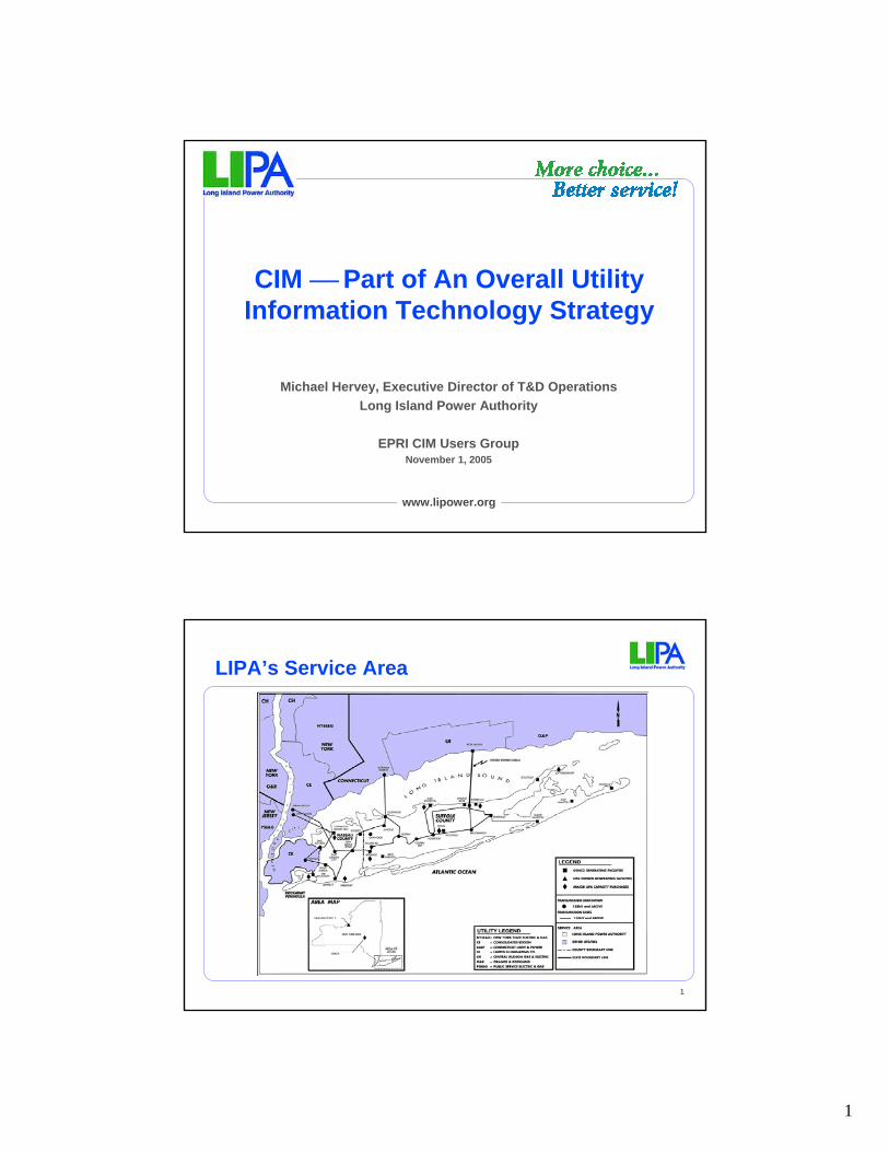
LIPA’s Vision of CIM
Integration Bus
System Network
Operations
T&DPlanning
& Support
Marketing&
Customer Care
FinancialManagement
Data WarehousesDigital
Dashboard
OAGCIM
5
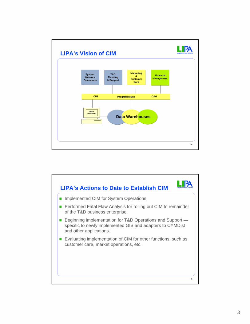
LIPA’s Actions to Date to Establish CIM
Implemented CIM for System Operations.
Performed Fatal Flaw Analysis for rolling out CIM to remainder of the T&D business enterprise.
Beginning implementation for T&D Operations and Support —specific to newly implemented GIS and adapters to CYMDistand other applications.
Evaluating implementation of CIM for other functions, such as customer care, market operations, etc.

4
6
Fatal Flaw Analysis — Advantages Creates a common data model– Everybody needs one.– Why reinvent the wheel?
CIM is extensible– Missing data elements can be added through the standards process.
No delay in software development– Approval of standards can occur after implementation…CIM is in
continuous evolution.Widely accepted– 40 vendors, over 60 applications and almost 60 utilities — piggy back on
best-in-class experience.Cost savings– Faster implementation of new systems and modules.– Ability to stage CIM implementation as new systems are added or major
modifications are made to existing systems.
7
Fatal Flaw Analysis — Risks & StrategiesMaturity of CIM– Over ten years in use.
Not a database– Which is a good thing since it establishes logical model.– But physical model can be created to fit individual organizations needs.
Limited number of applications– Expect continued growth as model is extended to T&D, power markets,
and customer care.Utilities use different naming conventions– Use of wrappers/adapters is easier to build than rewriting interfaces.
Concerns over throughput of integration bus– Can be mitigated by layering of applications, but the CIM architecture
remains.
5
8
Results of Fatal Flaw Analysis of CIM Helped Develop LIPA’s Plan Going Forward
Remain committed to CIM as THE architecture.
Continue to extend CIM/IB to remainder of the LIPA enterprise.
Take advantage of major system upgrades or replacements to control timing and costs of CIM/IB implementation.
Increase LIPA’s flexibility to add new service providers and/or IT systems as market conditions change and long term strategies evolve.
9
Questions?

1
1 Information ServicesEPRI CIM Meeting November 1, 2005
The Industry’s Need for CIM
Terry TylerTVA
EPRI CIM/GID International Conference
November 1, 2005
2 Information ServicesEPRI CIM Meeting November 1, 2005
What do the following have in common?What do the following have in common?
• APQC
• SCOR
• MIMOSA
• IAI
• ISO 15926
• CIM
• SOA

2
3 Information ServicesEPRI CIM Meeting November 1, 2005
Each of these standards organizations want to play a role in the meta data modeling and naming to make this integration model work
Each of these standards organizations want to play a role in the meta data modeling and naming to make this integration model work
Meter Data
SCADADevice
CustomerMeterAgent
Accounting
Finance
Supply Chain
Revenue Billing
Project Mgt
Trading & Risk Mgt
OutageMgt
Field ForceAutomation
Work & AssetMgt
Control RoomOperations
Markets CustomerSwitching
C/PartyB2B
Project Costing
Corp Data Store
Ops DataStore
Data Warehouses
InternetInternet
Msg Broker & data transformation
Integration Hub
Portal
Call CentreGridOperations
HR
Third Party Billing
CAR
4 Information ServicesEPRI CIM Meeting November 1, 2005
Design Time Process for
Model Driven Integration

3
5 Information ServicesEPRI CIM Meeting November 1, 2005
In case this is not confusing enough
Look what the future might hold
6 Information ServicesEPRI CIM Meeting November 1, 2005
“Technopoly – Culture’s Surrender to Technology”“Technopoly – Culture’s Surrender to Technology”
Source: IBM GIO 2004

4
7 Information ServicesEPRI CIM Meeting November 1, 2005
Energy Trends Point to Unique Opportunities for Investors, Industry, and Policy-Makers, Reports Clean Edge
Energy Trends Point to Unique Opportunities for Investors, Industry, and Policy-Makers, Reports Clean Edge
• A variety of issues have aligned to offer unique opportunities in the clean-energy sector including security issues, energy uncertainty, the need for power reliability, technological advances, environmental issues, the rise of the developing world, and investment commitments by government, corporations, and venture capitalists.
• The report reveals five trends to watch in the near- to mid-term: – The Energy Web: the emerging marriage of the energy, telecom, and software sectors that is
creating a whole new breed of ``smart'' appliances, buildings, and vehicles – The Hydrogen “ECONOMY” Infrastructure: the assemblage of products, services, and systems that
will enable the manufacture, storage, and transportation of hydrogen for use in stationary and portable fuel cells
– Bringing Solar to Scale: the mass commercialization and build-up of large-scale solar-cell manufacturing that will result in significant economies of scale
– The Microtization of Fuel Cells: the application of micro fuel cells for use in a wide range of portable electronic devices including cell phones, personal digital assistants, and laptop computers
– “NANOTECHNOLOGY” Carbon Nanotubes: tiny fabricated tube-shaped molecules that are optimal for hydrogen storage -- and are getting close to commercial viability.
Source: Cleanedge.com January 3, 2002
8 Information ServicesEPRI CIM Meeting November 1, 2005
Nanotechnology is fundamentally change sensors allowing them to be embedded in every aspect of the business setting the stage for a new era of maintenance practices and operations
Nanotechnology is fundamentally change sensors allowing them to be embedded in every aspect of the business setting the stage for a new era of maintenance practices and operations
SystemWAN
Internet or VPN
Aggregate
Premises
RemoteDiagnostics and Service
Controls
HVAC Sensors & Controls
SecuritySensors & Controls
LightingMonitors & Controls
Automated Data
Collection
Equipment Sensors and
Controls
Aggregate
Analyze
eCommerce Information
Business Applications
PIM / Messaging
WebSphere AS
Service Applications
Lifestyle / Fun
Enterprise data
Application data
WebSpherePortal
Services
e-business / LOBApplications
WebSphereMQ Broker
Act
Act
Application
WebSphere Everyplace Embedded Software
U/IComm
Security
Base OS
JVM
Apps
Device/Application Management
DataManagement
Analyze
OperationsWEA/WES Server
Connectivity Content Handling
Security
SubscriptionServices
Optimization
Mgmt Services
FFA / SFAApplications Act
Shell has already deployed this technology in the e-Station, fundamentally changing the profitability model for this portion of the business
5
9 Information ServicesEPRI CIM Meeting November 1, 2005
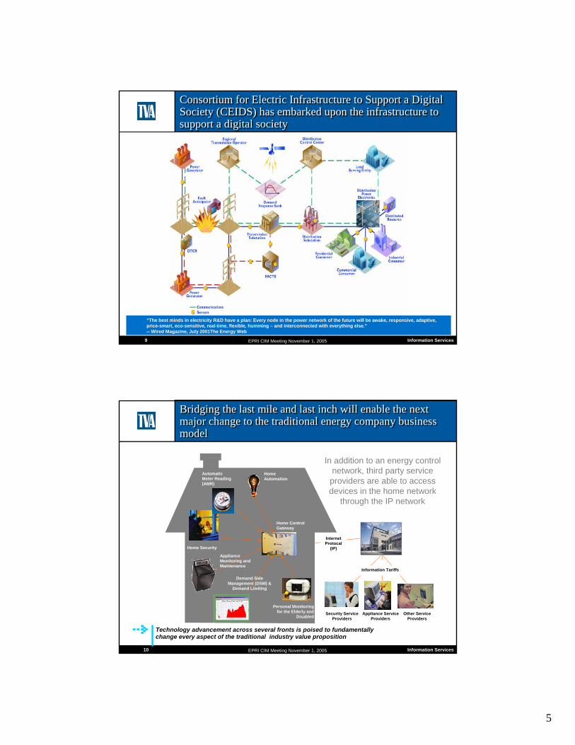
Consortium for Electric Infrastructure to Support a Digital Society (CEIDS) has embarked upon the infrastructure to support a digital society
Consortium for Electric Infrastructure to Support a Digital Society (CEIDS) has embarked upon the infrastructure to support a digital society
“The best minds in electricity R&D have a plan: Every node in the power network of the future will be awake, responsive, adaptive, price-smart, eco-sensitive, real-time, flexible, humming – and interconnected with everything else.”-- Wired Magazine, July 2001The Energy Web
10 Information ServicesEPRI CIM Meeting November 1, 2005
Bridging the last mile and last inch will enable the next major change to the traditional energy company business model
Bridging the last mile and last inch will enable the next major change to the traditional energy company business model
In addition to an energy control network, third party service providers are able to access devices in the home network
through the IP network
Home Automation
Automatic Meter Reading(AMR)
Home Security
Appliance Monitoring and Maintenance
Demand Side Management (DSM) &
Demand Limiting
Personal Monitoring for the Elderly and
Disabled
Home Control Gateway
Security Service Providers
Other Service Providers
Appliance Service Providers
Internet Protocal
(IP)
$Information Tariffs
Technology advancement across several fronts is poised to fundamentally change every aspect of the traditional industry value proposition

6
11 Information ServicesEPRI CIM Meeting November 1, 2005
Our ability to manage is shifting out along the asset availability continuumOur ability to manage is shifting out along the asset availability continuum
Past Present Future
Asset Breaks
Corrective Maintenance
Asset will Break
Someday
Interval Maintenance
Asset May Be Failing
Condition Based Maintenance
Asset Functions Per Business Plan
Continuous Asset Monitoring Within Context
of Business Plan Maximizes Asset
Usage and Management in
Real Time
12 Information ServicesEPRI CIM Meeting November 1, 2005
Managing in near real time shifts a company’s focus and style of managementManaging in near real time shifts a company’s focus and style of management
Source: The Adaptive Enterprise, Dr Stephan Haeckel

7
13 Information ServicesEPRI CIM Meeting November 1, 2005
Who are the leaders in making this transition to managing in near real time?Who are the leaders in making this transition to managing in near real time?
• e-Bay• Cisco• Delta Airlines• Alcoa• Dupont• GE• Landstar• Motorola
• McDonalds
• IBM• GM
• Xcel Energy• Exelon• Edison International
• Genentech
• World class benchmark companies
14 Information ServicesEPRI CIM Meeting November 1, 2005
In conclusionIn conclusion
• Models like CIM and compliance thereto are critical today but will be absolutely essential to future company success
• Technology is making matters worse today and will significantly complicate matters in the not too distant future
• Your attendance at this event is a first step• Your commitment to supporting the future of the CIM
model are essential to all of our collective future success

8
15 Information ServicesEPRI CIM Meeting November 1, 2005
Appendix
Additional Information on Other Efforts Similar to CIM
16 Information ServicesEPRI CIM Meeting November 1, 2005
ISO 15926ISO 15926
• The Oil and Gas (ISO 15926) : Integration of life-cycle data for oil and gas production facilities (Oil & Gas). This initiative includes standardization of the data associated with the engineering construction and operation of oil and gas production facilities.
• ISO 15926-2:2003 specifies a conceptual data model for computer representation of technical information about process plants. The information required by the following activities is within the scope of ISO 15926-2:2003:
– specification of requirements to produce, process, and transport process materials; – specification of functions required to produce and process the required materials, including the following:
• hydrocarbon process and conditioning systems, • injected gas and water conditioning and injection systems, • oil and gas product transport systems, • safety and control systems, • electricity generation and supply systems, • steam generation and supply systems, • structures, • buildings and accommodation;
– specification and selection of materials and equipment to provide the required production and processing functions, including information about market available materials and equipment;
– installation and commissioning of plant equipment; – production and process operations, including process conditions and consumption, yields and quality of process
material; – maintenance and replacement of equipment.
http://www.iso.ch/iso/en/CatalogueDetailPage.CatalogueDetail?CSNUMBER=29557&ICS1=25&ICS2=40&ICS3=40

9
17 Information ServicesEPRI CIM Meeting November 1, 2005
Machinery Information Management Open Systems AllianceMachinery Information Management Open Systems Alliance
• MIMOSA is a not-for-profit trade association dedicated to developing and encouraging the adoption of open information standards for Operations and Maintenance in manufacturing, fleet, and facility environments. MIMOSA's open standards enable collaborative asset lifecycle management in both commercial and military applications. MIMOSA is composed of progressive process and discrete manufacturing corporations, facility management companies, military organizations, capital equipment OEMs, and suppliers of asset management software systems including Human-Machine Interfaces (HMI), Manufacturing Execution Systems (MES), Plant Asset Management (PAM) systems, Enterprise Resource Planning (ERP), Enterprise Asset Management (EAM/CMMS) systems, Operational Data Historian Systems (ODHS), and Condition Monitoring (CM) systems.
http://www.mimosa.org
18 Information ServicesEPRI CIM Meeting November 1, 2005
Supply Chain Reference Operations model (SCOR)Supply Chain Reference Operations model (SCOR)
• The Supply-Chain Council was organized in 1996 by PittiglioRabin Todd & McGrath (PRTM) and AMR Research, and initially included 69 voluntary member companies. The Supply-Chain Council now has closer to 1,000 corporate members world-wide. The Supply-Chain Council's membership consists primarily practitioners representing a broad cross section of industries, including manufacturers, services, distributors, and retailers.
The Supply-Chain Operations Reference-model (SCOR) is a process reference model that has been developed and endorsed by the Supply-Chain Council as the cross-industry standard diagnostic tool for supply-chain management. SCOR enables users to address, improve, and communicate supply-chain management practices within and between all interested parties.
http://www.supply-chain.org

10
19 Information ServicesEPRI CIM Meeting November 1, 2005
International Alliance for Interoperability (IAI)International Alliance for Interoperability (IAI)
• IAI is an alliance of organizations dedicated to bring about a coordinated change for the improvement of productivity and efficiency in theconstruction and facilities management industry (Building Smart). Our members engage in national-industrial programmes that aim to change the organisation, process and technology of the industry.
• IFC/ifcXML Common Model: We have developed a common building model (ifc/ifcxml), which forms the basis of our technologies that delivers our Building Smart mission. Click here for latest IFC/ifcXML specifications of the model.
Software: Major vendors of Building Information Model (BIM) have implemented support for IFC in their products. Many downstream applications (such as Structural engineering, HVAC design, Thermal analysis, Code checking, Quantity take-off, Cost estimation, etc.) have also implemented IFC support in their products. Click here for the lists of available IFC compatible software.
http://www.iai-international.org
1
1
STANDARDS- IntelliGrid and CIM/GID
Integrated Energy and Communications System
Architecture
Rich LordanTechnology Director
EPRI
November 1, 2005
2 Copyright © 2005 Electric Power Research Institute, Inc. All rights reserved.
IntelliGrid Mission
MissionTo accelerate the
transformation of the power delivery
infrastructure into the intelligent grid needed to
support our future society.

2
3 Copyright © 2005 Electric Power Research Institute, Inc. All rights reserved.
Vision:– Self-Healing and
Adaptive– Interactive with
consumers and markets
– Optimized to make best use of resources and equipment
– Integrated– Secure
Vision of a Transformed Electricity Enterprise
4 Copyright © 2005 Electric Power Research Institute, Inc. All rights reserved.
How is the Intelligent Grid Created?The Premise
• Intelligent Systems will be deployed by utilities to perform a specific application that addresses a business or regulatory driver
• Every utility will have different drivers; therefore, each utility will deploy different Intelligent Systems at different rates; therefore, taking a different path towards creating their intelligent grid.
• Over time new applications will reuse pieces for existing Intelligent Systems

3
5 Copyright © 2005 Electric Power Research Institute, Inc. All rights reserved.
How is the Intelligent Grid Created?
• Start with existing intelligent systems• Progressively link them together• Add new knowledge and technologies• Create NEW intelligent systems with
– Wider scope– Greater ability to adapt
• For example…
6 Copyright © 2005 Electric Power Research Institute, Inc. All rights reserved.
Asset ManagementAsset Management
Example: Asset Management
• A utility sets up basic equipment monitoring…• Adds a few more advanced capabilities…• With the addition of some advanced technology,• Creates a next-generation automation application
Substation SCADA
Substation SCADA
Automated Dispatch
Automated Dispatch
Breaker MonitoringBreaker
Monitoring
Transformer Monitoring
Transformer Monitoring
PredictiveLife Cycle
Models

4
7 Copyright © 2005 Electric Power Research Institute, Inc. All rights reserved.
And so on…
• The complexity of the system keeps increasing• New technologies increase intelligence
AutomaticIslanding
AutomaticIslanding
AssetManagement
AssetManagement
End-to-EndDemand
Response
End-to-EndDemand
Response OutageManagement
OutageManagement
ReliabilityManagement
Thru PQ
ReliabilityManagement
Thru PQ
Providing Data ServicesProviding
Data Services
Wide-Area Measurement
& Control
Wide-Area Measurement
& Control
8 Copyright © 2005 Electric Power Research Institute, Inc. All rights reserved.
Creating the Intelligent GridAutomaticIslanding
AutomaticIslanding
Real-TimeContingency
Analysis
Real-TimeContingency
Analysis
AssetManagement
AssetManagement
End-to-EndDemand
Response
End-to-EndDemand
Response OutageManagement
OutageManagement
ReliabilityManagement
Thru PQ
ReliabilityManagement
Thru PQ
Providing Data ServicesProviding
Data Services
The Intelligent GridThe Intelligent Grid
5
9 Copyright © 2005 Electric Power Research Institute, Inc. All rights reserved.
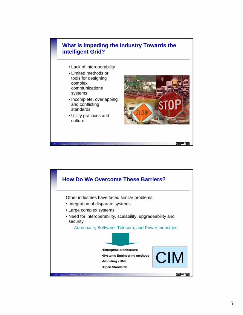
What is Impeding the Industry Towards the intelligent Grid?
• Lack of interoperability• Limited methods or
tools for designing complex communications systems
• Incomplete, overlapping and conflicting standards
• Utility practices and culture
10 Copyright © 2005 Electric Power Research Institute, Inc. All rights reserved.
How Do We Overcome These Barriers?
Other industries have faced similar problems • Integration of disparate systems• Large complex systems• Need for interoperability, scalability, upgradeability and
securityAerospace, Software, Telecom, and Power Industries
•Enterprise architecture
•Systems Engineering methods
•Modeling - UML
•Open StandardsCIM
6
11 Copyright © 2005 Electric Power Research Institute, Inc. All rights reserved.
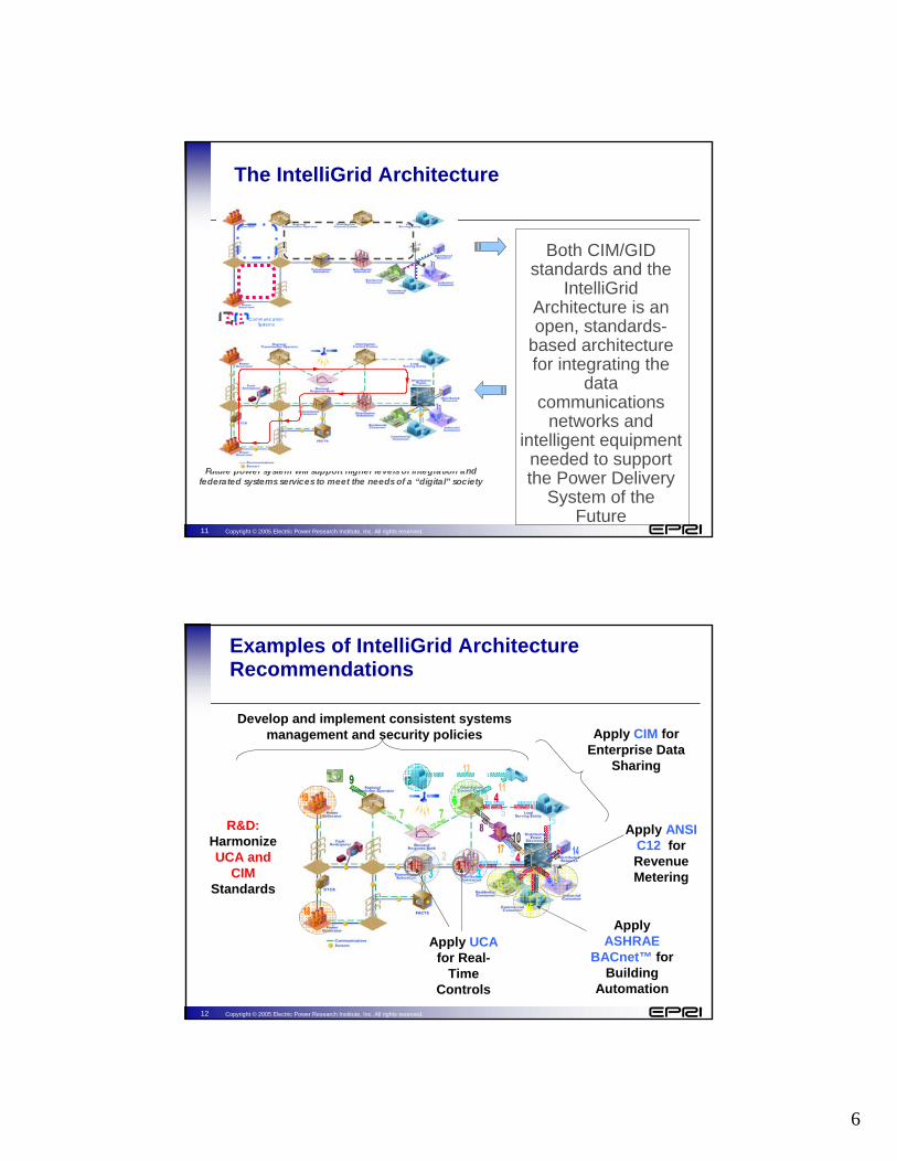
Both CIM/GID standards and the
IntelliGrid Architecture is an open, standards-
based architecture for integrating the
data communications
networks and intelligent equipment
needed to support the Power Delivery
System of the Future
Future power system will support higher levels of integration and federated systems services to meet the needs of a “digital” society
The IntelliGrid Architecture
Communication Systems
12 Copyright © 2005 Electric Power Research Institute, Inc. All rights reserved.
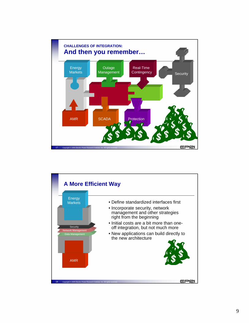
Examples of IntelliGrid Architecture Recommendations
Apply ASHRAE
BACnet™ for Building
Automation
Apply ANSI C12 for Revenue Metering
Apply UCAfor Real-
Time Controls
Apply CIM for Enterprise Data
Sharing
R&D:Harmonize UCA and
CIMStandards
Develop and implement consistent systems management and security policies

7
13 Copyright © 2005 Electric Power Research Institute, Inc. All rights reserved.
CHALLENGES OF INTEGRATION:
Building Isolated Systems
• Utilities tend to develop intelligent systems in isolation
• For example, AMR and participation in energy markets
• Neither project is typically developed with the other in mind.
AMR
EnergyMarkets
14 Copyright © 2005 Electric Power Research Institute, Inc. All rights reserved.
CHALLENGES OF INTEGRATION:
One-Off Integration
• Integration is typically done after the fact
• Cost is significant
AMR
EnergyMarkets

8
15 Copyright © 2005 Electric Power Research Institute, Inc. All rights reserved.
CHALLENGES OF INTEGRATION:
Doing it the Next Time
• Now want to link in new systems
• Must first make the old system expandable
• Then must do another “one-off”integration
AMR
EnergyMarkets
SCADA
OutageManagement
16 Copyright © 2005 Electric Power Research Institute, Inc. All rights reserved.
CHALLENGES OF INTEGRATION:
And again…
AMR
EnergyMarkets
SCADA
OutageManagement
Protection
Real-Time Contingency
9
17 Copyright © 2005 Electric Power Research Institute, Inc. All rights reserved.
CHALLENGES OF INTEGRATION:
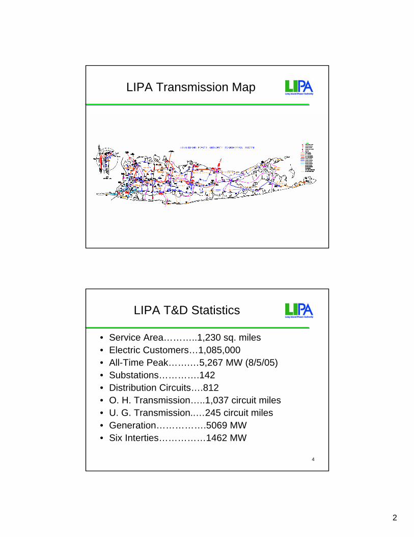
And then you remember…
AMR
EnergyMarkets
SCADA
OutageManagement
Protection
Real-Time Contingency Security
18 Copyright © 2005 Electric Power Research Institute, Inc. All rights reserved.
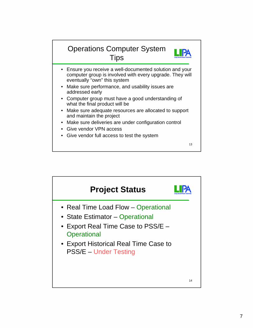
AMR
A More Efficient Way
• Define standardized interfaces first• Incorporate security, network
management and other strategies right from the beginning
• Initial costs are a bit more than one-off integration, but not much more
• New applications can build directly to the new architecture
Data ManagementNetwork Management
Security
EnergyMarkets

10
19 Copyright © 2005 Electric Power Research Institute, Inc. All rights reserved.
AMR
The Next Phase• Can re-use the
development from the first phase
• Expansion was expected• Adaptation to legacy
systems was planned in advance
• Overall costs much lower
SCADA
Data ManagementNetwork Management
Security
EnergyMarkets
OutageManagement
OutageManagement
SCADA
20 Copyright © 2005 Electric Power Research Institute, Inc. All rights reserved.
AMR
And so on…
• Benefits INCREASE with time
• Opposite of the old way
ProtectionSCADA
Data ManagementNetwork Management
Security
EnergyMarkets
OutageManagement
Real-Time Contingency
OutageManagement
SCADA Protection

11
21 Copyright © 2005 Electric Power Research Institute, Inc. All rights reserved.
The IntelliGrid Architecture Project Processes
Establish the Vision of
the Future Energy System
Work with Stakeholders to Refine Vision, Define
Requirements and Analyze
Available for Download
and Public Use:www.epri-intelligrid.com
www.intelligrid.info
Methods and Tools
Recommendations
Initial Results
22 Copyright © 2005 Electric Power Research Institute, Inc. All rights reserved.
Intelligrid Consortium Partners
U.S. Utilities• Public Service Electric & Gas • Long Island Power Authority• Salt River Project• TXU• We Energies• Bonneville Power
Administration • Consolidated Edison Company• New York Power Authority
International Utilities• Polish Power Grid Company• Electricite de France
Public Agencies• U.S. Department of Energy• California Energy Commission
Manufacturers• ABB• Hitachi
Technology
Providers
Public Sector
Utilities

12
23 Copyright © 2005 Electric Power Research Institute, Inc. All rights reserved.
Demonstration Projects
• California Energy Commission/California Investor Owned Utilities: Demand Response/Advanced Metering Development
• Texas Utilities: Advanced Metering Infrastructure Development
• Long Island Power Authority: Enterprise Architecture Development
• Salt River Project: Transfer Station Equipment Monitoring• Electricite de France: Application of IntelliGrid Unified
Modeling Language Model

1
Rev. Sept. 16, 2005 1
Real-Time Power Flow in a Planning Environment at LIPA
Dave Becker
CIM/GID Conf – November 1,2005
2
Who Is LIPA?
• State utility located on Long Island New York
• Long Island Power Authority owns T&D• Keyspan owns the power plants and
manage T&D for LIPA
2
3
LIPA Transmission Map
4
LIPA T&D Statistics
• Service Area………..1,230 sq. miles• Electric Customers…1,085,000• All-Time Peak…….…5,267 MW (8/5/05)• Substations………….142• Distribution Circuits….812• O. H. Transmission…..1,037 circuit miles• U. G. Transmission..…245 circuit miles• Generation…………….5069 MW• Six Interties……………1462 MW

3
5
Control Center Project Requirements
• Accurately model the transmission system for any point in time– Past EMS model not available– Past EMS SCADA is available– Prior Procedure:
• Modify a planning load flow to match real time• Very time consuming and low accuracy
6
Control Center Proposed Solution
• Build CIM model from GE Harris EMS model• Track network changes to recreate historical model• Retrieve Measurement Data from PI Historian• Run PSS/O to support Operations with real-time
load flow analyses• Create PSS/E load flow models for Electric Planning
PSS/O State Estimator
(for time T1)
PSS/E Equivalent Case
(for time T1)
CIM Model(at time T1)
PI Historian(at time T1)

4
7
What is GID & UIB?
Generic Interface Definition:Emerging standard for exchanging CIM dataComposed of messages protocols:
GDA: Generic Data AccessHSDA: High-speed Data AccessTSDA: Time-series Data AccessGES: Generic Eventing and Sequencing
Utility Integration Bus: SISCO’s Implementation of the GID
8
Solution Architecture
EMS
ICCP
CIMPowerModels
UIBUIBUIB
PSS/ODMS
PSS/E
CIM
PowerModels
UIB PIAdapter Archive
PI
PowerModels
MeasurementData
MeasurementData
EquipmentModels
CIMVirtual Data Warehouse
AnalysisApplications
PowerModels
MMW
Maximo
TOTS
Others
.
.
.
MeasurementData
Model Update

5
9
PSS/O Display
10
Experience Gained So Far on CIM Application
• It is critical to define in great detail the scope of the application. The Control Center Project took a year to spec out
• All the departments involved must buy in the project
• Requires long term management support• Detailed implementation schedule must be
established• Schedule of acceptance tests must be
developed• Commitment to update the model must be
established

6
11
Major Issues
• Make sure all EMS data points including quality points are broadcasted to the UIB bus
• Resolve all State Estimator convergence problems
• Accurately map all data points to model
12
State Estimator Convergence Tips
• Data Points and Quality points required• Add data points for outside world• Add Pseudo measurements to the outside world to make
the area observable• Small distribution transformers may cause low voltage if
high side telemetering is not accurate• Correct transformer and Phase Shifter tap settings• Breaker position (open/close) must match equipment
flow• Develop a step procedure that checks key data which
prevent the State Estimator to converge
7
13
Operations Computer System Tips
• Ensure you receive a well-documented solution and your computer group is involved with every upgrade. They will eventually “own” this system
• Make sure performance, and usability issues are addressed early
• Computer group must have a good understanding of what the final product will be
• Make sure adequate resources are allocated to support and maintain the project
• Make sure deliveries are under configuration control• Give vendor VPN access• Give vendor full access to test the system
14
Project Status
• Real Time Load Flow – Operational• State Estimator – Operational• Export Real Time Case to PSS/E –
Operational• Export Historical Real Time Case to
PSS/E – Under Testing
8
15
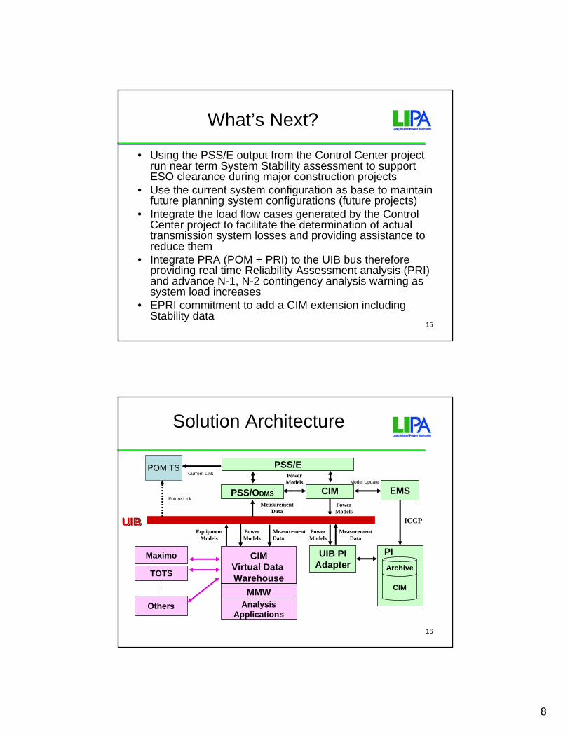
What’s Next?
• Using the PSS/E output from the Control Center project run near term System Stability assessment to support ESO clearance during major construction projects
• Use the current system configuration as base to maintain future planning system configurations (future projects)
• Integrate the load flow cases generated by the Control Center project to facilitate the determination of actual transmission system losses and providing assistance to reduce them
• Integrate PRA (POM + PRI) to the UIB bus therefore providing real time Reliability Assessment analysis (PRI) and advance N-1, N-2 contingency analysis warning as system load increases
• EPRI commitment to add a CIM extension including Stability data
16
Solution Architecture
EMS
ICCP
CIMPowerModels
UIBUIBUIB
PSS/ODMS
PSS/E
CIM
PowerModels
UIB PIAdapter Archive
PI
PowerModels
MeasurementData
MeasurementData
EquipmentModels
CIMVirtual Data Warehouse
AnalysisApplications
PowerModels
MMW
Maximo
TOTS
Others
.
.
.
MeasurementData
POM TS
Future Link
Current Link
Model Update

9
17
Naming Conventions and Definitions
• CIM – Common Information Model• PSS/E = Power System Simulator for Engineering (Version 29+)• PSS/O = Power System Simulator for Operations (Version 7+)• ECI = EPRI CIM Installer (a base set of ODMS functionality)• EMS = Energy Management System• PI = XA/21 EMS Real Time Data Repository• PNA = Power Network Analysis• PSM = Power System Model• MMW = Maintenance Management Workstation• XA/21 = General Electric Network Solution EMS System.• UIB = Utility Integration Bus• GDA = General Data Access• TSDA = Time-Series Data Access• HSDA = High-Speed Data Access• GID = Generic Interface Definition• GES = Generic Event Sequencer• ESO = Electric System Operations• LIPA = Long Island Power Authority• DPE = Distribution Performance Engineering• EP&F = Electric Planning and Forecasting• VDW = Virtual Data Warehouse• ODBC = Open Data Base Connectivity• XML = Extensible Markup Language• PRA = Physical Reliability Assessment• PRI = Physical Reliability Index• POM = Physical and Operational Margins• V&R Energy = EPRI Contractor which develop POM
1
TVA and CIM
Internal Integrity and InterchangeGreg Congleton
TVA
TPSIM
Data Repository

2
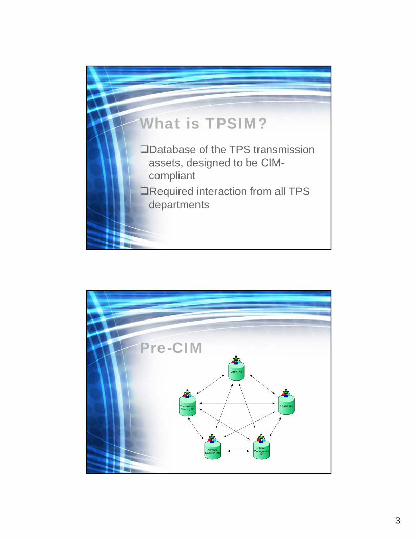
What is TPSIM?
Transmission / Power SupplyInformation Model
What is TPSIM?Database of the TPS transmission assets, designed to be CIM-compliant
3
What is TPSIM?Database of the TPS transmission assets, designed to be CIM-compliantRequired interaction from all TPS departments
Pre-CIM
4
Introducing the CIM• Potential for increased
connectivity• Data consistency
Mapping to the CIM• Manual collection of data• Identification table connecting CIM
to TPS
5
Extending the CIM• Added TPS-specific tables• TPS Identifiers, application-
specific requirements, equipment types
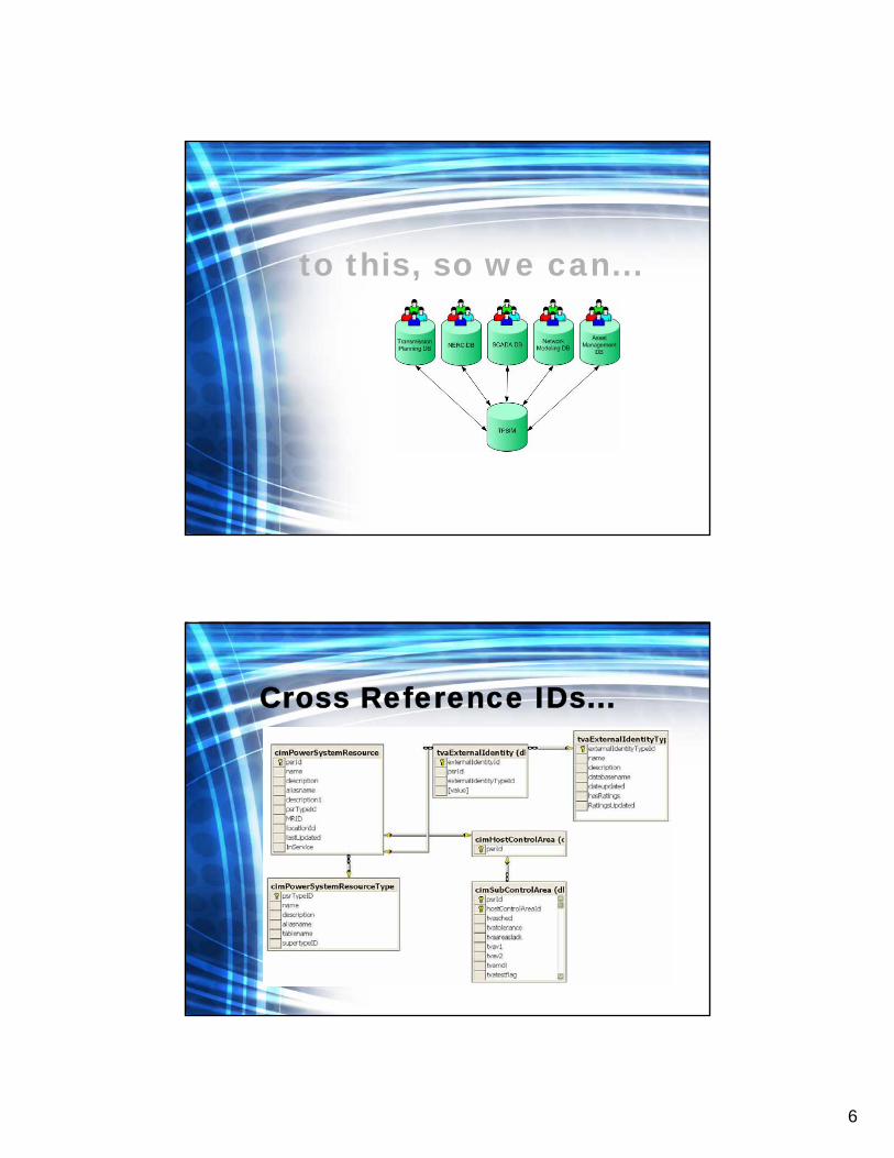
From this…
6
to this, so we can...
Cross Reference IDs...

7
do this.
Benefits• Better interaction among
departments• Increased data access• Better data consistency• Plug-and-Play

8
More work ahead.
Challenges• Mapping data to multiple
departments• Limited resources• Maintaining data integrity

9
Web Services
Data Retrieval
The Problem

10
The Scope• Over 300 different applications• Over 100 different databases
The Solution• Provide a standard Web Service
interface for all data requests
• Have the data content mapped to CIM and TVACIM labels

11
The Solution
The Solution

12
The Solution
The Solution

13
XML
<Substation diffgr:id="Substation16" msdata:rowOrder="15" diffgr:hasChanges="inserted" TPSIMID="161" TPSIMName="8SULLIVA" TPSIMDescription="SULLIVAN, 500 KV GENERAL, EJ1" ANAVoltage="500" TPSIMSubControlAreaID="27" SubControlArea="TVA" />
<Substation diffgr:id="Substation17" msdata:rowOrder="16" diffgr:hasChanges="inserted" TPSIMID="162" TPSIMName="5CALVERT" TPSIMDescription="CALVERT, KY" ANAVoltage="161" TPSIMSubControlAreaID="27" SubControlArea="TVA" />
CIM Map<CimMap diffgr:id="CimMap1" msdata:rowOrder="0" diffgr:hasChanges="inserted" FieldName="TPSIMID" CimName="Substation.tvaid" /> <CimMap diffgr:id="CimMap2" msdata:rowOrder="1" diffgr:hasChanges="inserted" FieldName="TPSIMName" CimName="Substation.aliasName" /> <CimMap diffgr:id="CimMap3" msdata:rowOrder="2" diffgr:hasChanges="inserted" FieldName="TPSIMDescription" CimName="Substation.description" /> <CimMap diffgr:id="CimMap4" msdata:rowOrder="3" diffgr:hasChanges="inserted" FieldName="ANAVoltage" CimName="Substation.VoltageLevel.BaseVoltage.nominalVoltage.value" /> <CimMap diffgr:id="CimMap5" msdata:rowOrder="4" diffgr:hasChanges="inserted" FieldName="TPSIMSubControlAreaID" CimName="Substation.SubControlArea.tvaid" /> <CimMap diffgr:id="CimMap6" msdata:rowOrder="5" diffgr:hasChanges="inserted" FieldName="SubControlArea" CimName="Substation.SubControlArea.aliasName" />

14
Swim Lane Model of Web Services Message Development
Why?• Provides an unambiguous label for
each data element• Provides potential 3rd party
recipients with the ability to accurately process the data

15
Summary• Better data integrity• Faster data access• Simpler data interchange
1
2005 November 1st Research and Development Division1
EDF Feedback on
CIM Standard
Eric Lambert and Andre MaizenerEDF R&D Division
2005 November 1st Research and Development Division2
PLAN
1. EDF GROUP
2. EDF R&D FEEDBACK: CIMERGY PROJECT
3. KEY POINTS TO IMPROVE CIM USAGE
4. CONCLUSION

2
2005 November 1st Research and Development Division3
1EDF GROUP : Key figures
2005 November 1st Research and Development Division4
1.1 EDF GROUP
• Annual income : 46.9 Billions € (56,3bi $) | 161000 employees• 42 .1 Millions of Customers | 125 000 MW of installed capacity
3
2005 November 1st Research and Development Division5
2EDF R&D CIMERGY PROJECT
2005 November 1st Research and Development Division6
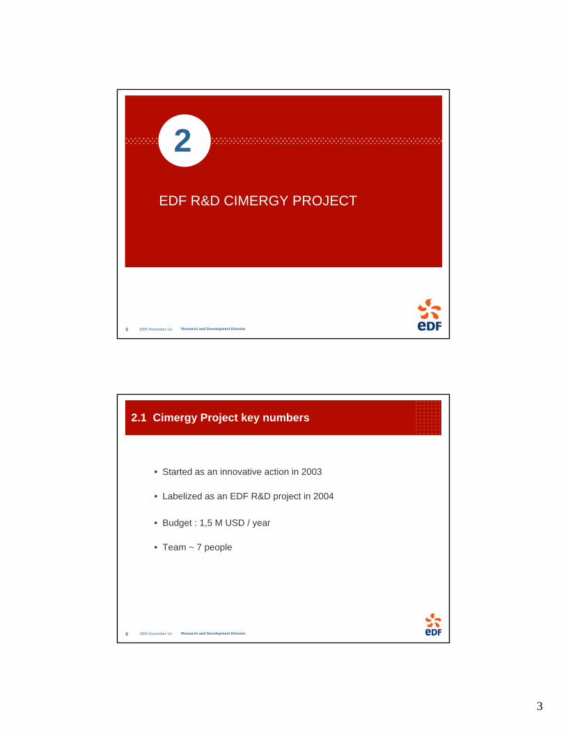
2.1 Cimergy Project key numbers
• Started as an innovative action in 2003
• Labelized as an EDF R&D project in 2004
• Budget : 1,5 M USD / year
• Team ~ 7 people

4
2005 November 1st Research and Development Division7
2.2 GOALS OF CIMERGY
• Define methodology and tools requirements in order to use IEC TC57 standards 61970, 61968.
• Participate actively in the TC57 standardization effort
• Promote the methodology inside EDFtry and provide related tools
• Promote the standard inside EDF
• Understand and help the harmonization process• IEC TC57 61970/61968 and 61850• IEC TC57 and UN-CEFACT, ETSO, ebIx
• Reduce the gap between IT people and Automation peopleTools should help
CIM training course for our people
2005 November 1st Research and Development Division8
MultiSpeak(NRECA)
OLEProcessControl(OPC)
WG14DMS
Coordination
WG19
WG13EMS
WGs 10Substations
OpenApplication
Group
WG7ControlCenters
TC57WG9
DistributionFeeders
EPRIUCA2ProjectEPRI
CCAPIProject
W3C
CIM/61850
ebXMLObjectMgmt.Group
WG17
WG16
WG18
OASIS
?
UCA : User groups
2.3 INTERNATIONAL CONTEXT

5
2005 November 1st Research and Development Division9
2.4 Technical Context : RDF, XSD for Transmission & Distribution
Power System DataAs CIM XML
Proprietary Power System Data ACIM
in UML
RDF Syntax
CIM RDFSchema
Specify
Reference
Proprietary Power System Data B
Power System DataAs CIM XML
IEC 61968 Part 3 to 10 CIM XSD Messages
2005 November 1st Research and Development Division10
2.5 CIM APPROACHES
• Bottom-up approach : field driven specific applications
• Load Profiling• Low Voltage Planification function• Medium Voltage Load Calculation• CIM API for PRAO (MV Planification Function)
• CIM API for Eurostag (HV Load Flow)• UCTE DEF to CIM CPSM format
• Generation Supervision prototype
• Top-Down Approach : from IM to Messages• Model Driven Integration approach• Based on the UN-CEFACT Modeling Methodology (called Core
Components Technical Specification), CIM Model, and ISO 1179« How to derive an XML Message from a UML model ? »
Uses cases completed with Distribution Division • CIM Products experimented : MDI (Xtensible Solutions) ,UIB (Sisco) • Customer switching
Distribution
Transmission (RTE)
Generation

6
2005 November 1st Research and Development Division11
2.6 Methodology : combining CIM & UN-CEFACT Core Component Technical Specification
, , A, , B
, , C , , D
, , E
1
, , F
CIM UML World
Constraints on Association + Assembling rules
, , A
, , B , , C , , D
, , E
1
, , F
1
, , C , , D
, , E
1
, , F
1
, , A+B
XML XSD
Generic CIM Message Schema generation
ReprocessedXML XSD
Constraintson attributes
2005 November 1st Research and Development Division12
Methodology : from Information Model to Message
Information Model
Contextual Information Model
Messages Model
syntaxic level(XML,…)
Selections
Restrictions

7
2005 November 1st Research and Development Division13
3KEY POINTS TO IMPROVE CIM usage
2005 November 1st Research and Development Division14
3.1 Publish official examples of CPSM compliantXML files and CIM compliant XML files
Justification :
Experience shows that CIM users don’t agree on the interpretation of the model.
Recommandation :
Validate IOP tests files as CPSM reference

8
2005 November 1st Research and Development Division15
3.2 Get a consistent approach for interoperabilitytests
Justification
Inconsistencies between CIM Model, nerc profile flag in UML, CPSM v1.9 specification, tool to generate RDF schema, and tool to validatean instance file. RDF schema does not contain all CIM UML elements
Recommandation
Have a consistent set (CIM model, Profiles, Generation & Validation Tools, Instance files, Documentation).
2005 November 1st Research and Development Division16
3.3 Publish a CIM standard release 2
Justification
Only 10% of CIM classes are used in interoperability tests
Recommandation
CIM standard release 2 (61970-301) should include
a major revision on comments (compliant to ISO1179)=> Some Utilities want to translate these definitions…
a major revision on Datatypessome packages provided by WG14

9
2005 November 1st Research and Development Division17
3.4 Global picture of CPSM real use in NorthAmerica
Justification
Promoting CPSM in Europe, and at least having a CIM profile for European countries based on CIM
Recommandation
Document explaining how CPSM is used, and which tools are used by North American Utilities.
2005 November 1st Research and Development Division18
3.5 Put in place in 2006 interoperability tests on Message Types provided by WG14
Justification
Having more interoperability, and using XML XSD message types
Recommandation
Set up a task force for organizing these tests in 2006Validate CIM for Distribution Networks

10
2005 November 1st Research and Development Division19
3.6 Put in place interoperability tests on CIM-61850
Justification
Important harmonization issue handled by IEC TC57 WG19
Recommandation
Set up a task force for organizing these tests in 2006
2005 November 1st Research and Development Division20
3.7 CIM profile including a Bus Branch Model
Justification
Several tools are based on a Bus Branch Model and not a Switch/nodemodel.
Recommandation
Propose this evolution in CPSM, or in a European Profile

11
2005 November 1st Research and Development Division21
3.8 Gap between CIM standard, and CIM workingversions
Justification
> Too many CIM working versions per year. > Difficulties to choose one> Big gap with the CIM standardized (61970-301)> Difficult to upgrade applications based on a previous CIM version
RecommandationA new CIM 61970-301 release, and less working versions
2005 November 1st Research and Development Division22
3.9 CIM User Group will be useful
– CIM approach and integration issues not easy to be explained atmanagerial level
– CIM users group can help to share experience and provide valuable
Materials

12
2005 November 1st Research and Development Division23
4CONCLUSION
2005 November 1st Research and Development Division24
4.1 To summarize…
• CIM provides an interesting integration scheme
• A new CIM standard release must be issued
• Interoperability test files and procedures must be pre-checked before interoperability tests
• Harmonization issues must be adressed (CIM, 61850, …)
• Combining CIM & UN-CEFACT standards seems to bevaluable

13
2005 November 1st Research and Development Division25
Thanks for your attention…and good workshop !
QUESTIONS ?

1
1
CAISO Perspective -Use of CIM/MDI Methodology to Implement
a Service Oriented Architecture (SOA)Terry Saxton
EPRI CIM/GID WorkshopMISO
November 2005
© 2003-2004 Xtensible Solutions, Inc. 2
Topics
•Introduction•Business and technology drivers•Service Oriented Architecture (SOA)•MDI/CIM – enabling SOA•Benefits

2
© 2003-2004 Xtensible Solutions, Inc. 3
Introduction
• CAISO is in the process of designing a new power market system– Multi-year program that involves many vendors, new systems, as
well as numerous legacy systems• Includes EMS, Full Network Model, Outage Management, PI
Historian, Market Systems, many others• External interfaces to Market Participants included
• Integration Competency Center decided on a Service Oriented Architecture (SOA) for the integration framework– Based on Web services– CIM and Model Driven Integration (MDI) methodology used to
define information exchange• The ISO is to achieve flexibility, scalability, and cost
savings through this approach
© 2003-2004 Xtensible Solutions, Inc. 4
Business and Technology Drivers
• Need to integrate technology provided by many vendors with significant technical diversity
• Increase the agility/flexibility of the integrated solution –change is the only constant!
• Increase the quality of data – as a public good corporation data is a critical asset and must be managed as such
• Reduce cost of implementation and maintenance• Integration goes beyond sharing of information, it needs
to support process integration and business intelligence.• Ensure that all new systems and applications are “built-to-
integrate” and achieve loose coupling• Meet performance and availability requirements
3
© 2003-2004 Xtensible Solutions, Inc. 5
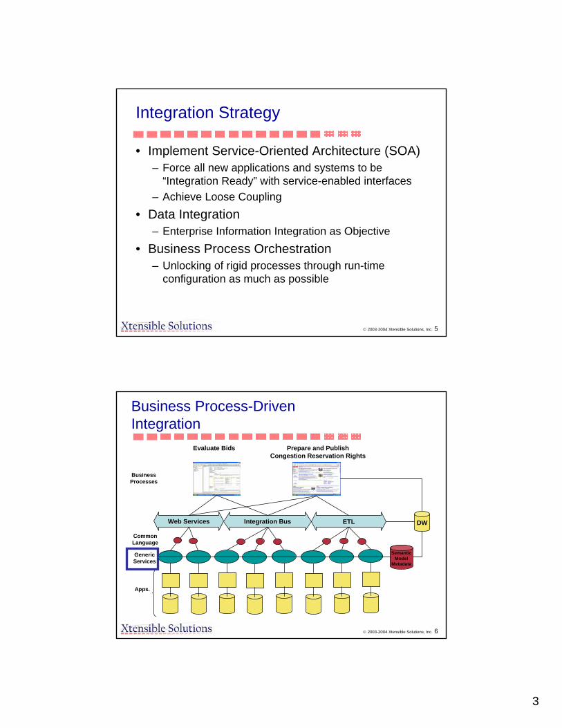
Integration Strategy
• Implement Service-Oriented Architecture (SOA)– Force all new applications and systems to be
“Integration Ready” with service-enabled interfaces– Achieve Loose Coupling
• Data Integration– Enterprise Information Integration as Objective
• Business Process Orchestration– Unlocking of rigid processes through run-time
configuration as much as possible
© 2003-2004 Xtensible Solutions, Inc. 6
ETLIntegration BusWeb Services
Apps.
GenericServices
Evaluate Bids
DW
Prepare and PublishCongestion Reservation Rights
CommonLanguage
SemanticModel
Metadata
Business Process-Driven Integration
Business Processes

4
© 2003-2004 Xtensible Solutions, Inc. 7
Service-Oriented Architecture
Consumer
ProviderBroker
“Services”Repository
Discov
er Subscribe
Publish
© 2003-2004 Xtensible Solutions, Inc. 8
Interface vs. Service
BA
Integration Layer
BroadcastService
transport
ReceiveService
ServiceOrchestrator
1 1
2
3

5
© 2003-2004 Xtensible Solutions, Inc. 9
Service Definition Guidelines
• BPMs– Gathering and reviewing business processes, systems,
applications, and databases information• Use Cases and Sequence Diagrams
– Develop/Elaborate To-Be service orchestration requirements in the forms of Use Cases and Sequence Diagrams
• CIM/CME– Develop common semantic based service payload
definition in the form of the UML diagram– Extend the CIM/CME, where necessary, to
accommodate CAISO requirements– The extended CIM/CME is the Common Semantic
Model for the MRTU program
(Slide from Stipe Fustar, KEMA)
© 2003-2004 Xtensible Solutions, Inc. 10
• Payload - Create CIM base and service payload XML Schema files– Map source and target data format(s) to the common
semantic model based service payload definitions. Document any business rules of service payload and mappings
• Payload Template– Verify and validate XML Schema files, and create
sample XML instance data files for reference• WSDL
– Develop WSDL service definition files using a WSDL template, and validate WSDL files
• Document the service definition artifacts in one document for a given business integration (interface) area
Service Definition Guidelines (cont’d)
(Slide from Stipe Fustar, KEMA)
6
© 2003-2004 Xtensible Solutions, Inc. 11
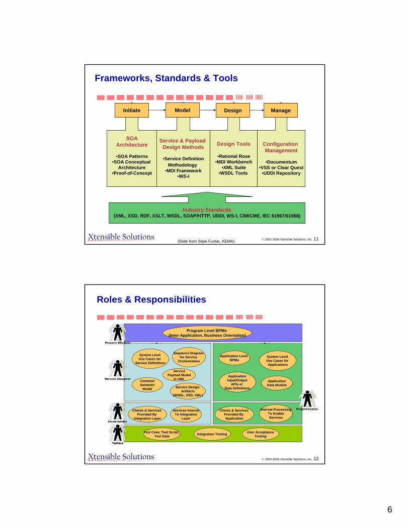
Frameworks, Standards & Tools
Industry Standards(XML, XSD, RDF, XSLT, WSDL, SOAP/HTTP, UDDI, WS-I, CIM/CME, IEC 61967/61968)
SOAArchitecture
•SOA Patterns•SOA Conceptual
Architecture•Proof-of-Concept
Service & Payload Design Methods
•Service DefinitionMethodology
•MDI Framework•WS-I
Design Tools
•Rational Rose•MDI Workbench
•XML Suite•WSDL Tools
Configuration Management
•Documentum•VSS or Clear Quest
•UDDI Repository
Initiate Model Design Manage
(Slide from Stipe Fustar, KEMA)
© 2003-2004 Xtensible Solutions, Inc. 12
Roles & Responsibilities
System Level Use Cases for
Service Definitions
Application Level BPMs
System Level Use Cases for Applications
Sequence Diagram for Service
Orchestration
ApplicationData Models
ApplicationInput/Output
APIs or Data Definitions
CommonSemantic
Model
ServicePayload Model
In UML
Service Design Artifacts
(WSDL, XSD, XML)
Clients & Services Provided By
Integration Layer
Services InternalTo Integration
Layer
Clients & Services Provided By Application
Internal ProcessingTo EnableServices
Test Case, Test Script, Test Data Integration Testing
Program Level BPMs(Inter-Application, Business Orientation)
User AcceptanceTesting

7
© 2003-2004 Xtensible Solutions, Inc. 13
MDI/CIM Enabled SOA Design
Common InformationModel (CIM)Process Models Message Models
(XSD)
© 2003-2004 Xtensible Solutions, Inc. 14
Interface Examples:
These interfaces are implemented by the vendors to surface information currently within custody to the enterprise.
EnterpriseVendorgetResourceInfo(XML) XML
Information Sharing
These interfaces are implemented by vendors to allow systems to receive information as it becomes available. This indicates a subscription type interest in data.
EAIVendorreceiveCleanBidSet(XML)
Information Interest
These interfaces are for transferring information and releasing custody.
VendorCAISOpublishCleanBidSet(XML)
Information Transfer
These interfaces are for creating or modifying information within a system of record.
EnterpriseVendorsubmitBid(XML)Information Creation
DescriptionUtilized byImplemented by
ExampleInterface Type
(Slide from Stipe Fustar, KEMA)
8
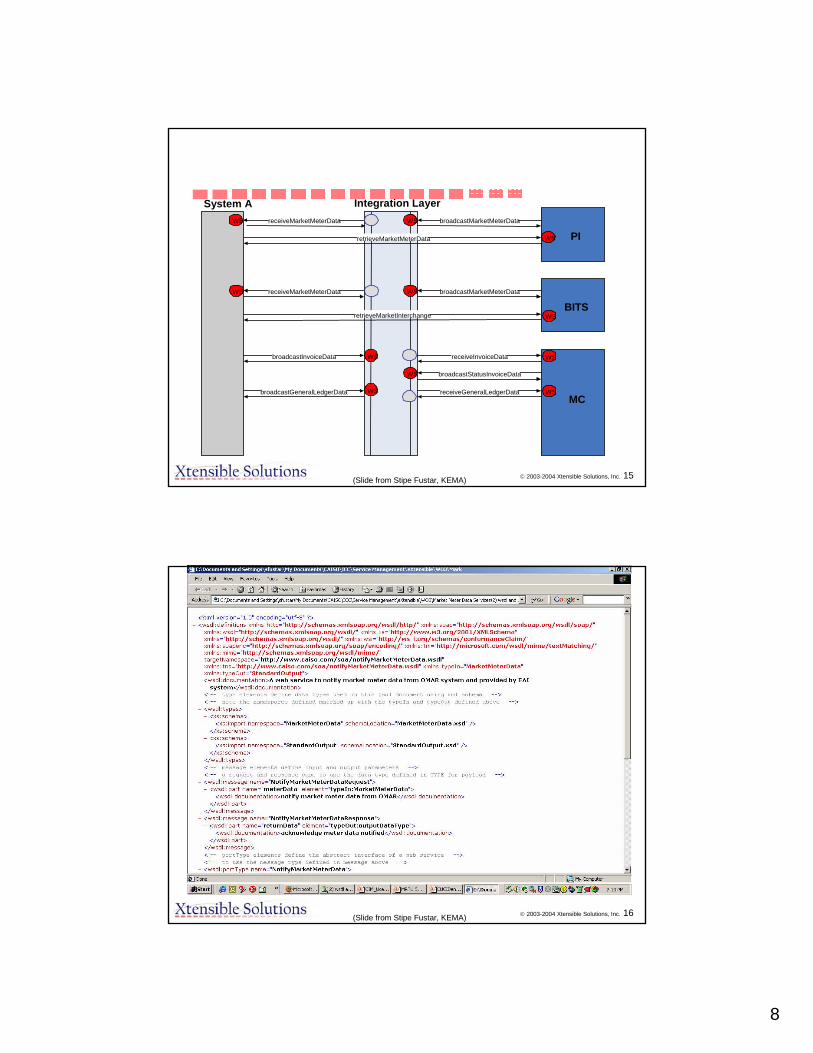
© 2003-2004 Xtensible Solutions, Inc. 15
System A Integration Layer
PI
BITS
MC
broadcastMarketMeterDataWS
retrieveMarketMeterData WS
broadcastMarketMeterData
WSretrieveMarketInterchange
WS
receiveMarketMeterDataWS
receiveMarketMeterDataWS
broadcastInvoiceData WS
broadcastGeneralLedgerData WS
receiveInvoiceData WS
receiveGeneralLedgerData WS
broadcastStatusInvoiceDataWS
(Slide from Stipe Fustar, KEMA)
© 2003-2004 Xtensible Solutions, Inc. 16(Slide from Stipe Fustar, KEMA)

9
© 2003-2004 Xtensible Solutions, Inc. 17(Slide from Stipe Fustar, KEMA)
© 2003-2004 Xtensible Solutions, Inc. 18
Vision Of Standard Services
• Leverages CIM– All payloads are forward engineered from CIM
• Standard Services – WSDL (serves as Interface Definition Language)– Message payloads
• XML Schema• XML Templates (message instances –
send/response)• Benefits
– True Plug-And-Play functionality– Publicly Available– Easy Interoperability Testing
• Can be provided On-line

10
© 2003-2004 Xtensible Solutions, Inc. 19
Benefits of MDI/CIM enabled SOA
• Expose information through common mechanism and common semantics
• Seamless information flow across the enterprise• Deliver the right information at the right place at the right
time• Enforcing data quality and consistency at the service level• Flexibility/agility in responding to business organisation
and process changes • Technology agnostic• Utilizes widely adopted and proven standards• Reduce total cost of ownership
• Provides traceability/mapping of business processes
© 2003-2004 Xtensible Solutions, Inc. 20
Status
• Examples of the systems that have been service enabled:– Areva (Settlement)– Siemens (Bid Interface, SCUC)– ABB (EMS)– Nexant (CRR)– Legacy applications
• One of most important applications of CIM standards– Gives control of the integration environment to the utility– Information exchange contents/format driven by business
process/use case exchange of business objects• Not driven by application provider interfaces• WSDLs form contract with suppliers for information exchange based
on the CIM

1
Status of CIM/GID/MessagingStatus of CIM/GID/MessagingStandardsStandards
EPRI CIM/GID International EPRI CIM/GID International ConferenceConference
MISO, IndianapolisMISO, IndianapolisNovember 2005November 2005
Terry SaxtonTerry SaxtonXtensible Solutions, Inc.Xtensible Solutions, Inc.Minneapolis, MinnesotaMinneapolis, [email protected]@xtensible.net
The IEC Common Information Model The IEC Common Information Model (CIM) (CIM) -- What Is It?What Is It?
A Unified Modeling Language (UML) based information model A Unified Modeling Language (UML) based information model representing realrepresenting real--world objects and information entities exchanged world objects and information entities exchanged within the value chain of the electric power industrywithin the value chain of the electric power industry
Maintained in IBMMaintained in IBM’’s Rational Rose modeling tool. s Rational Rose modeling tool. A tool to enable A tool to enable iintegrationntegration and and information exchangeinformation exchangeEnable data access in a standard wayEnable data access in a standard way
Common language to navigate and access complex data structures iCommon language to navigate and access complex data structures in any n any databasedatabase
Provides a hierarchical view of data for browsing and access witProvides a hierarchical view of data for browsing and access with no knowledge h no knowledge of actual logical schemaof actual logical schema
Inspiration for logical data schemas (e.g., for an operational dInspiration for logical data schemas (e.g., for an operational data store)ata store)Enable integration of applications/systemsEnable integration of applications/systems
Provides a common language for exchanging messages between systeProvides a common language for exchanging messages between systemsmsBasis for defining information exchange modelsBasis for defining information exchange models
Not tied to a particular applicationNot tied to a particular application’’s view of the worlds view of the worldBut permits same model to be used by all applications to facilitBut permits same model to be used by all applications to facilitate ate information sharing between applicationsinformation sharing between applicationsAlso provides consistent view of the world by operators regardleAlso provides consistent view of the world by operators regardless of which ss of which application user interface they are usingapplication user interface they are using

2
Sample Power System ModelSample Power System Model
Generator AC Line Substation
Company
Load
Operates
Operates
Belongs To
Member Of
Owns
Load Area
Connects To
Connects To
Connects To
WG14Enterprise
/ DMS
SPAG
WG13EMS
ObjectMgmt.Group
WG 10Substations
OpenApplication
Group AHWG 07“Harmonization”
TC57
WG16Markets
EPRIUCA2
ProjectEPRICCAPI & CME
Projects
W3C
CIM
Open GISConsortium
(GML)
CIM Development CollaborationCIM Development Collaboration
ISOIT Standards
Initiatives

3
TC57 Reference ArchitectureTC57 Reference Architecture
Market Operation Apps
60870-6-503App Services
SCADA Apps EMS Apps DMS Apps Engineering & Maintenance Apps
ExternalIT Apps
Data Acquisition and Control Front-End / Gateway / Proxy Server / Mapping Services / Role-based Access Control
61850-8-1Mapping to MMS
TC13 WG14 Meter
Standards
61334
60870-5101&
104
61970 Component Interface Specification (CIS)
61968 SIDMS for Enterprise Application Integration (EAI)
61970 / 61968 Common Information Model (CIM)
Inter-Application Messaging Middleware (specified in XML; mapped to appropriate protocols)
61850 Substation Devices
61850 IED Field Devices &
Distribution Feeders
60870-6TASE.2
Other Control Centers
60870-5RTUs or
SubstationSystems
IEDs, Relays, Meters, Switchgear, CTs, VTs
End
-to-E
nd S
ecur
ity S
tand
ards
and
Rec
omm
enda
tions
(wor
k in
pro
gres
s)
IEC TC57 Reference Architecture
External Systems(Symmetric client/server
protocols)
Specific Communication Services Mappings
Specific Object Mappings
ApplicationInterfaces
Equipment AndSystem Interfaces
TelecontrolCommunications
Media and Services
Communication Industry Standard Protocol Stacks(ISO/TCP/IP/Ethernet)
XMLMessaging
(work inprogress)
Protocol Profiles
XML Messaging
External Systems (e.g., Substations)
WANCommunications
Media and Services
FieldDevices
Utility CustomersEnergyMarket Participants Other BusinessesUtility
Service Providers
Net
wor
k, S
yste
m, a
nd D
ata
Man
agem
ent
(futu
re)
TC13 WG14
*Notes: 1) Solid colors correlate different parts of protocols within the architecture.2) Non-solid patterns represent areas that are future work, or work in progress, or related work provided by another IEC TC.
61850-7-2 ACSI
61850-7-3, 7-4 Object Models
CustomerMeters
Peer-to-Peer 61850 overSubstation bus and Process bus
60870-6-802Object Models
60870-6-703Protocols
Field Object Models
Application To Application (A2A)and Business To Business
(B2B) Communications
Where are all the CIMWhere are all the CIM--Related Standards Related Standards Found (IEC official standards and drafts)Found (IEC official standards and drafts)
CIM as an information modelCIM as an information modelStandardizes classes, attributes, and relationships in UMLStandardizes classes, attributes, and relationships in UMLProvides dictionary of standard objectsProvides dictionary of standard objects6197061970--3XX series and 619683XX series and 61968--1111
CIM as common languageCIM as common languageStandardizes Messages in XMLStandardizes Messages in XMLProvides sentences with selected to parts of CIM to support specProvides sentences with selected to parts of CIM to support specific ific use casesuse cases6196861968--3 to 103 to 10
Generic Interfaces (PIM)Generic Interfaces (PIM)6197061970--401 to 449401 to 449
Component Interface Specifications (PIM)Component Interface Specifications (PIM)Specific interface services plus selected CIM contentSpecific interface services plus selected CIM content6197061970--450 to 499450 to 499
Technology Mappings for CIS (PSM)Technology Mappings for CIS (PSM)6197061970--5XX5XX

4
CIM Electronic ModelsCIM Electronic ModelsIEC Official ReleasesIEC Official Releases
Owned by IECOwned by IECDirectly related to paper standardsDirectly related to paper standards
CIM UML models (61970CIM UML models (61970--3XX and 619683XX and 61968--11)11)CIMCIM--based message schemas (61968based message schemas (61968--3 to 10)3 to 10)1:1 correspondence1:1 correspondence
Unofficial releasesUnofficial releasesMay contain additional packages and/or other changesMay contain additional packages and/or other changes
Ex: CIM with market extensionsEx: CIM with market extensionsRDF Schema versions in XMLRDF Schema versions in XML
Based on some identified CIM UML releaseBased on some identified CIM UML releaseCurrently electronic models available on various Web sitesCurrently electronic models available on various Web sitesNear term planNear term plan
All electronic versions managed by CIM Model Manager (CMM)All electronic versions managed by CIM Model Manager (CMM)Available on CIM User Group Web siteAvailable on CIM User Group Web siteProjectProject--specific versions may also be maintained in repositoryspecific versions may also be maintained in repository
CIM PackagesCIM Packages
Generation
Domain
Wires
LoadModel
Core
Meas
Topology
Outage Protection
Financial
EnergyScheduling
Reservation
SCADA
Core2
Assets Documen-tation
Consumer
OAGMessages
ERPSupport
61968
61970
WG13/16

5
IEC TC57 WG13 IEC TC57 WG13 -- EMS APIEMS API
ObjectivesObjectivesReduce the cost and time needed to Reduce the cost and time needed to add new applicationsadd new applicationsto an EMS or other system to an EMS or other system Improve the capability to Improve the capability to exchange informationexchange information between between disparate systems both within and external to the control disparate systems both within and external to the control center environmentcenter environment
Technical approachTechnical approachProvide an Provide an integration frameworkintegration framework for interconnecting for interconnecting existing applications/systems that isexisting applications/systems that is
Based on a Based on a common architecture and information common architecture and information modelmodel–– CIMCIM–– Generic ServicesGeneric Services
Independent of the underlying technology (PIM)Independent of the underlying technology (PIM)–– Mappings to specific technologies (PSM)Mappings to specific technologies (PSM)
61970 series of standards61970 series of standards
61970 Document Structure61970 Document StructurePart 1: Guidelines and General RequirementsPart 1: Guidelines and General RequirementsPart 2: GlossaryPart 2: GlossaryPart 3XX: Common Information Model (CIM)Part 3XX: Common Information Model (CIM)
Provides common language for information exchange Provides common language for information exchange Part 4XX: Component Interface Specifications (CIS)Part 4XX: Component Interface Specifications (CIS)
Provides Platform Independent Models (PIM)Provides Platform Independent Models (PIM)Part 5XX: CIS Technology MappingsPart 5XX: CIS Technology Mappings
Provides Platform Specific Models (PSM)Provides Platform Specific Models (PSM)Correlation with 4XX documentsCorrelation with 4XX documents
Ex: 403 maps to a 503 documentEx: 403 maps to a 503 documentSpecific technologies identified with a Specific technologies identified with a ““--XX””
--0 through 3 are reserved for future use0 through 3 are reserved for future use--4 for XML4 for XML--5 for CORBA 5 for CORBA --6 for COM 6 for COM --7 for 7 for ‘‘CC’’--8 for Web Services 8 for Web Services --9 for Java9 for Java
Ex: C implementation of GDA Ex: C implementation of GDA –– 403 and 503403 and 503--7 7

6
4XX 4XX –– Generic ServicesGeneric Services
Part 401: CIS FrameworkPart 401: CIS FrameworkProvides an overview of the CIS series of standards and an Provides an overview of the CIS series of standards and an explanation of how to use the standards in system explanation of how to use the standards in system implementations and system integration projectsimplementations and system integration projects
Parts 402 Parts 402 –– 449: Generic services to be supported by 449: Generic services to be supported by component interfacescomponent interfaces
Describe in narrative text and Unified Modeling Language Describe in narrative text and Unified Modeling Language (UML) notation the interface functionality that is (UML) notation the interface functionality that is standardizedstandardizedDefine the generic services that can be used by any Define the generic services that can be used by any application to exchange information with another application application to exchange information with another application or for public data accessor for public data access
OPC
OMG
IEC
Current GIDCurrent GID

7
4XX 4XX –– Specific Interfaces Specific Interfaces Part 450: CIS Information Exchange ModelPart 450: CIS Information Exchange Model
Provides an overview of the use case process used to define infoProvides an overview of the use case process used to define information rmation content and examples of system integration using the CIS standarcontent and examples of system integration using the CIS standardsdsProvides common requirements for the future Part 451Provides common requirements for the future Part 451--499 specifications499 specifications
Parts 451 Parts 451 –– 499: Specifications that address the specific information 499: Specifications that address the specific information exchange requirements for typical application categoriesexchange requirements for typical application categories
Define the information content of the standard information exchaDefine the information content of the standard information exchanges nges between applicationsbetween applicationsDefined as events but may be exchanged in a variety of ways, incDefined as events but may be exchanged in a variety of ways, includingluding
Published as messagesPublished as messagesNotifications followed by a requestNotifications followed by a requestXML documentsXML documents
Identifies properties and methods to be supported by each interfIdentifies properties and methods to be supported by each interfaceaceSupporting documentation includes use cases and event sequence Supporting documentation includes use cases and event sequence diagrams.diagrams.
WG13 Document TreeWG13 Document Tree
Part 1 - Guidelines and General Requirements
Part 2 - Glossary
Part 301 - CIM Base Part 302 – Energy Scheduling, Financial, Reservations
Part 401 - CIS Overview and Framework
Part 402 -Common Services
Part 403 -Generic Data Access
Part 404 -Hi-Speed Data Access
Part 405 -Generic Eventing & Sub
Part 501 -CIM RDF Schema
Part 503-5 GDA CORBA Mapping
Part 503-7 GDA C Language Mapping
Part 407 -Historical Data Access
Part 450 - CIS Information Exchange Model Guide
Part 451 SCADA CIS
Part 500 - Technology Mappings
Part 552-4 CIM XML Model Exch. Format
Part 452 CIM Model Exchange Spec.
Part 453 Graphics Exchange

8
Document StatusDocument Status
CDCIM XML Model Exchange Format552-4 (503)
FDISCIM RDF Schema501
WDGraphics Exchange453
WDCIM Model Exchange Specification 452
WDSCADA CIS451
WDCIS Information Exchange Model Specification Guide (CIS Data Content)450
CDHistorical Data Access407
CDGeneric Eventing and Subscription (Events and Subscription)405
CDHigh Speed Data Access404
CDGeneric Data Access (Request and Reply )403
CDCommon Services (Base Services)402
DTSCIS Overview and Framework401
CD on holdCIM Energy Scheduling, Reservations, Financial302
ISCIM Base301
TSGlossary2
FDISGuidelines and General Requirements1
Current StatusTitlePart
WG13 WG13 –– Current FocusCurrent Focus
Progress Part 4XX and 5XX standardsProgress Part 4XX and 5XX standardsParts 402 Parts 402 –– 407 new drafts based on UML407 new drafts based on UMLPart 453 Common Graphics ExchangePart 453 Common Graphics Exchange
Part 3XX CIM MaintenancePart 3XX CIM MaintenanceCIM IssuesCIM IssuesCIM Maintenance proceduresCIM Maintenance proceduresCIM Release 2CIM Release 2
Part 301 CIM Base Second EditionPart 301 CIM Base Second EditionPart 302 Market OperationsPart 302 Market Operations
Coordination with new CIM User GroupCoordination with new CIM User Group

9
MeterReading &
Control
MeterReading &
Control
Utility ControlCenter
Utility ControlCenter
NetworkExpansionPlanning
NetworkExpansionPlanning
CustomerInquiry
CustomerInquiry
NetworkOperationNetwork
Operation
Records& Asset
Management
Records& Asset
Management
OperationalPlanning &
Optimization
OperationalPlanning &
Optimization
IEC 61968CompliantInterface
Architecture
IEC 61968CompliantInterface
Architecture
Maintenance&
Construction
Maintenance&
Construction
UtilityBusinessSystems
(ERP, Billing,Energy trading,other systems)
UtilityBusinessSystems
(ERP, Billing,Energy trading,other systems)
Corporate LAN
Corporate LAN
Distribution AutomationDistribution Automation
Substation Protection,Monitoring and Control
Substation Protection,Monitoring and Control
RTU Communications RTU Communications
Working Group 14:Establishing A Common Language For
Enterprise Application IntegrationIn the IEC 61968 Series of Standards
Information: www.cimuser.org
Canada China Finland France Germany Netherlands Russian Federation Spain Sweden Switzerland South Africa United Kingdom United States Serbia & Montenegro Japan
IEC TC57 WG14: Interface Reference Model (IRM)IEC TC57 WG14: Interface Reference Model (IRM)The Framework Used For Identifying Message TypesThe Framework Used For Identifying Message Types
IEC 61968 Compliant Middleware Services
(NE)Network
ExtensionPlanning
(CS)CustomerSupport
(MR)Meter
Reading &Control
(AM)Records &
AssetManagement
(MC)Maintenance
&Construction
InterfaceStandard: Part 4
InterfaceStandard: Part 6
InterfaceStandard: Part 7
InterfaceStandard: Part 8
InterfaceStandard: Part 9
(ACT)CustomerAccount
Management
(FIN)Financial
(PRM)Premises
(HR)Human
Resources
(EMS)Energy
Management &Energy Trading
(RET)Retail
InterfaceStandard: Part 10
(SC)Supply
Chain andLogistics
(NO)Network
Operation
InterfaceStandard: Part 3
(OP)OperationalPlanning &
Optimization
InterfaceStandard: Part 5
InterfaceStandard: Part 10
InterfaceStandard: Part 10
InterfaceStandard: Part 10
InterfaceStandard: Part 10
InterfaceStandard: Part 10
InterfaceStandard: Part 10
Electric Distribution NetworkPlanning, Constructing,
Maintaining, and Operating
Generation and Transmission Management,Enterprise Resource Planning, Supply Chain, and
General Corporate Services
Business FunctionsExternal To Distribution
Management
Distribution ManagementBusiness Functions
10
““The building of the tower of BabelThe building of the tower of Babel””by Pieter by Pieter BruegelBruegel, 1563, 1563Oil on oak panel, Oil on oak panel, KunsthistorischesKunsthistorisches Museum, ViennaMuseum, Vienna
Inter-ApplicationIntegration SolutionsAlways ExperienceScaling ProblemsWithout ACommon LanguageFor InformationExchange
MeteringReading
SubstationAutomation
DistributionManagement
DistWiresModel
GridWiresModel
DAC
CustomerInformation
VRU
AM/FM/GIS
DistributionAutomation
ERP
DataWarehouse
“Application Integration” = Middleware + Common Language
OntologicalRepository
Event History WorkManagement
...
EMS
= Generic Adapter TailoredFor Each Application
How Some Utility Implementations Are Using AHow Some Utility Implementations Are Using AStandardsStandards--Based Semantic Data Model Based Semantic Data Model
The “Common Language” provides a semantic layer based on the Utility’sOntology, which is derived from a combination of the IEC’s CommonInformation Model (CIM), Other Applicable Models, and Necessary Extensions
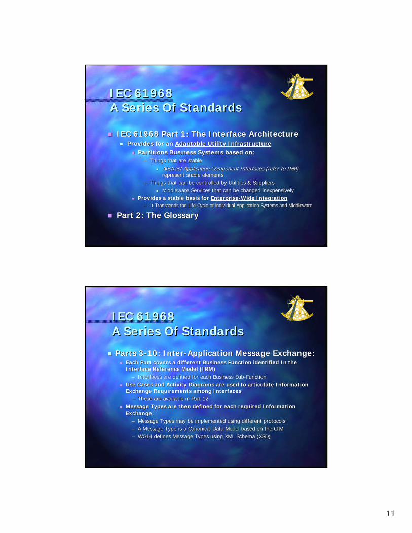
11
IEC 61968IEC 61968A Series Of StandardsA Series Of Standards
IEC 61968 Part 1: The Interface ArchitectureIEC 61968 Part 1: The Interface ArchitectureProvides for an Provides for an Adaptable Utility InfrastructureAdaptable Utility Infrastructure
Partitions Business Systems based on:Partitions Business Systems based on:–– Things that are stableThings that are stable
Abstract Application Component Interfaces (refer to IRM) Abstract Application Component Interfaces (refer to IRM) represent stable elementsrepresent stable elements
–– Things that can be controlled by Utilities & SuppliersThings that can be controlled by Utilities & SuppliersMiddleware Services that can be changed inexpensivelyMiddleware Services that can be changed inexpensively
Provides a stable basis for Provides a stable basis for EnterpriseEnterprise--Wide IntegrationWide Integration–– It Transcends the LifeIt Transcends the Life--Cycle of individual Application Systems and MiddlewareCycle of individual Application Systems and Middleware
Part 2: The Glossary Part 2: The Glossary
IEC 61968IEC 61968A Series Of StandardsA Series Of Standards
Parts 3Parts 3--10: Inter10: Inter--Application Message Exchange: Application Message Exchange: Each Part covers a different Business Function identified In theEach Part covers a different Business Function identified In theInterface Reference Model (IRM)Interface Reference Model (IRM)
–– Interfaces are defined for each Business SubInterfaces are defined for each Business Sub--FunctionFunctionUse Cases and Activity Diagrams are used to articulate InformatiUse Cases and Activity Diagrams are used to articulate Information on Exchange Requirements among InterfacesExchange Requirements among Interfaces
–– These are available in Part 12These are available in Part 12Message Types are then defined for each required Information Message Types are then defined for each required Information Exchange:Exchange:
–– Message Types may be implemented using different protocols Message Types may be implemented using different protocols –– A Message Type is a Canonical Data Model based on the CIMA Message Type is a Canonical Data Model based on the CIM–– WG14 defines Message Types using XML Schema (XSD)WG14 defines Message Types using XML Schema (XSD)

12
IEC 61968IEC 61968A Series Of StandardsA Series Of Standards
Part 11: Common Information ModelPart 11: Common Information Model–– The CIM defined by WG14, which is an extension of the The CIM defined by WG14, which is an extension of the
CIM that is defined by WG13 (IEC 61970).CIM that is defined by WG13 (IEC 61970).
Part 12: Technical Report: DMS Use Cases Part 12: Technical Report: DMS Use Cases –– Upon The Completion Of Parts 1Upon The Completion Of Parts 1--10, A Final Report Will 10, A Final Report Will
Be Submitted To IEC That Will Contain All Use Cases Be Submitted To IEC That Will Contain All Use Cases That Were Utilized During The Development Of IEC That Were Utilized During The Development Of IEC 61968.61968.
Part 13: Common Distribution Power System Part 13: Common Distribution Power System Model ExchangeModel Exchange
–– (XML RDF, compatible with 61970)(XML RDF, compatible with 61970)
Next Steps for 61968 Series of StandardsNext Steps for 61968 Series of StandardsPart 1: Interface Architecture and General RequirementsPart 1: Interface Architecture and General Requirements
–– (maintenance cycle) Revised document to IEC by 17 February 2006(maintenance cycle) Revised document to IEC by 17 February 2006Part 2: GlossaryPart 2: Glossary
–– (maintenance cycle) Revised document to IEC by 17 February 2006 (maintenance cycle) Revised document to IEC by 17 February 2006 (may be (may be necessary to delay based on coordination being performed by WG19necessary to delay based on coordination being performed by WG19))
Part 3: Network OperationsPart 3: Network Operations–– (maintenance cycle) Revised document to IEC by 17 February 2006(maintenance cycle) Revised document to IEC by 17 February 2006
Part 4: Records & Asset ManagementPart 4: Records & Asset Management–– CDV ready to go to IEC by 30 November 2005. However, since it wCDV ready to go to IEC by 30 November 2005. However, since it will be ill be
dependent on Part 1, it may be better to wait until Part 1 is redependent on Part 1, it may be better to wait until Part 1 is released. What is leased. What is the the IECIEC’’ss preference?preference?
Part 5: Operational Planning and Optimization Part 5: Operational Planning and Optimization –– NWIP & initial CD to IEC by 17 February 2007NWIP & initial CD to IEC by 17 February 2007
Part 6: Maintenance & ConstructionPart 6: Maintenance & Construction–– NWIP & initial CD to IEC by 17 February 2006 NWIP & initial CD to IEC by 17 February 2006
Part 7: Network Extension PlanningPart 7: Network Extension Planning–– NWIP & initial CD to IEC by 17 February 2007NWIP & initial CD to IEC by 17 February 2007
Part 8: Customer SupportPart 8: Customer Support–– NWIP & initial CD to IEC by 17 February 2006NWIP & initial CD to IEC by 17 February 2006
Part 9: Metering Reading and ControlPart 9: Metering Reading and Control–– Revised CD to IEC by 17 February 2006Revised CD to IEC by 17 February 2006
Part 11: Common Information Model for DMSPart 11: Common Information Model for DMS–– NWIP & initial CD to IEC by17 February 2006NWIP & initial CD to IEC by17 February 2006
Part 12: Use Case Technical ReportPart 12: Use Case Technical Report–– NWIP & initial CD to IEC by17 February 2006NWIP & initial CD to IEC by17 February 2006
Part 13: Common Distribution Power System ModelPart 13: Common Distribution Power System Model–– Revised CD to IEC by 31 December 2005Revised CD to IEC by 31 December 2005
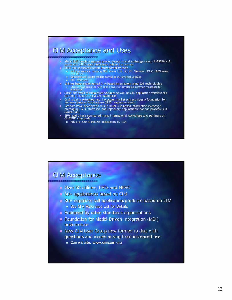
13
CIM Acceptance and UsesCIM Acceptance and UsesMany EMS vendors support power system model exchange using CIM/RMany EMS vendors support power system model exchange using CIM/RDF/XML, DF/XML, some with CIMsome with CIM--based databases behind the scenesbased databases behind the scenesEPRI has sponsored seven interoperability testsEPRI has sponsored seven interoperability tests
Multiple vendors, including ABB, Multiple vendors, including ABB, ArevaAreva, EDF, GE, PTI, Siemens, SISCO, SNC , EDF, GE, PTI, Siemens, SISCO, SNC LavalinLavalin, , and othersand othersComplete and partial models as well as incremental updatesComplete and partial models as well as incremental updatesGID interfacesGID interfaces
Utilities have implemented CIMUtilities have implemented CIM--based integration using EAI technologiesbased integration using EAI technologiesUtilities have used the CIM as the basis for developing common mUtilities have used the CIM as the basis for developing common messages for essages for integrationintegration
Asset and work management vendors as well as GIS application venAsset and work management vendors as well as GIS application vendors are dors are starting to support CIM/XSD standardsstarting to support CIM/XSD standardsCIM is being extended into the power market and provides a foundCIM is being extended into the power market and provides a foundation for ation for ServiceService--Oriented Architecture (SOA) implementationOriented Architecture (SOA) implementationVendors have developed tools to build CIMVendors have developed tools to build CIM--based information exchange based information exchange messaging, GID interfaces, and repository applications that can messaging, GID interfaces, and repository applications that can process CIMprocess CIM--aware dataaware dataEPRI and others sponsored many international workshops and seminEPRI and others sponsored many international workshops and seminars on ars on CIM/GID standardsCIM/GID standards
Nov 1Nov 1--4, 2005 at MISO in Indianapolis, IN, USA4, 2005 at MISO in Indianapolis, IN, USA
CIM AcceptanceCIM Acceptance
Over 50 utilities, Over 50 utilities, ISOsISOs and NERCand NERC60+ applications based on CIM60+ applications based on CIM30+ suppliers sell application/products based on CIM30+ suppliers sell application/products based on CIM
See CIM Reference List for DetailsSee CIM Reference List for Details
Endorsed by other standards organizationsEndorsed by other standards organizationsFoundation for ModelFoundation for Model--Driven Integration (MDI) Driven Integration (MDI) architecturearchitectureNew CIM User Group now formed to deal with New CIM User Group now formed to deal with questions and issues arising from increased usequestions and issues arising from increased use
Current site: Current site: www.cimuser.orgwww.cimuser.org

1
1
Reliability Coordinators’Perspective on CIM
David Zwergel
2
Reliability Coordination
What is Reliability Coordination?
The Reliability Coordinator has a wide area view, the operating tools, processes and procedures, including the authority, to prevent or mitigate emergency operating situations in both next-day analysis and during real-time conditions.
Why CIM is important to Reliability?
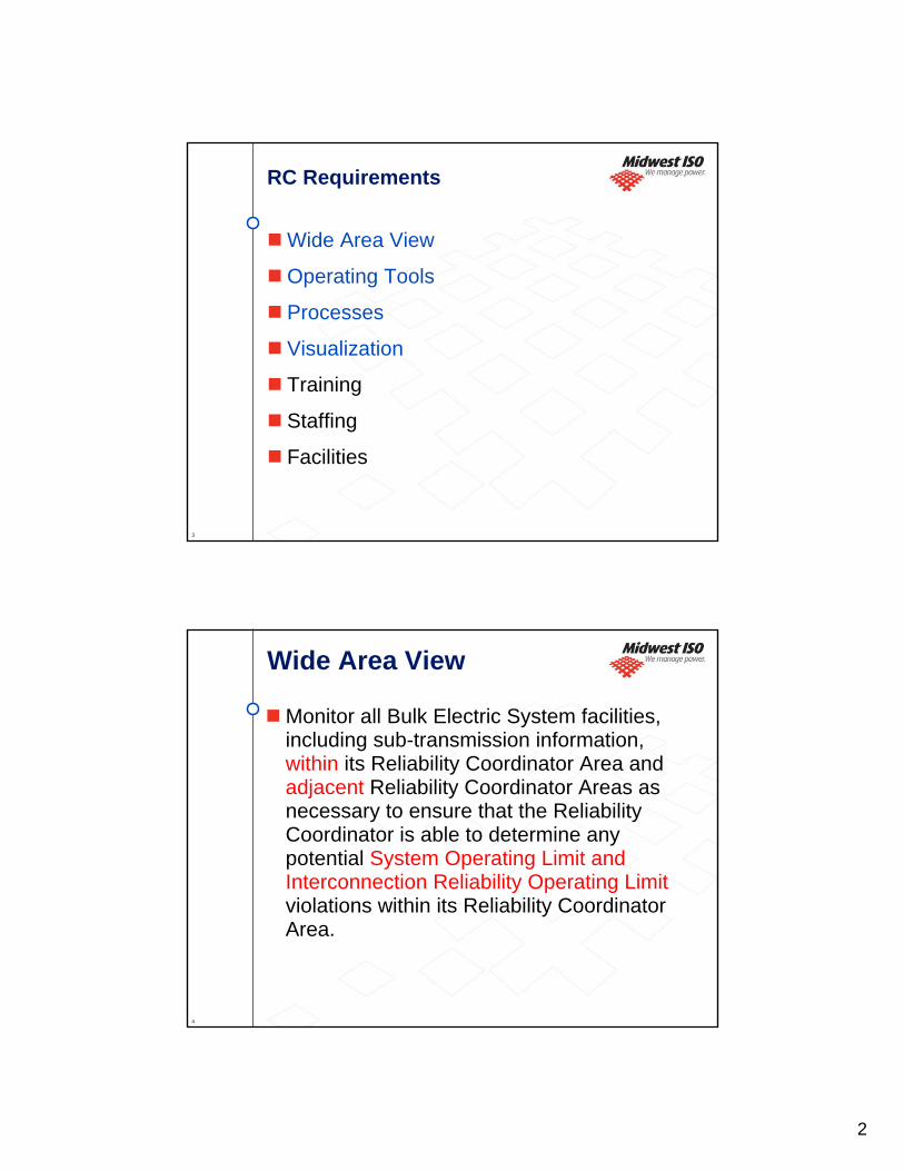
2
3
RC Requirements
Wide Area View
Operating Tools
Processes
Visualization
Training
Staffing
Facilities
4
Wide Area View
Monitor all Bulk Electric System facilities, including sub-transmission information, within its Reliability Coordinator Area and adjacent Reliability Coordinator Areas as necessary to ensure that the Reliability Coordinator is able to determine any potential System Operating Limit and Interconnection Reliability Operating Limitviolations within its Reliability Coordinator Area.
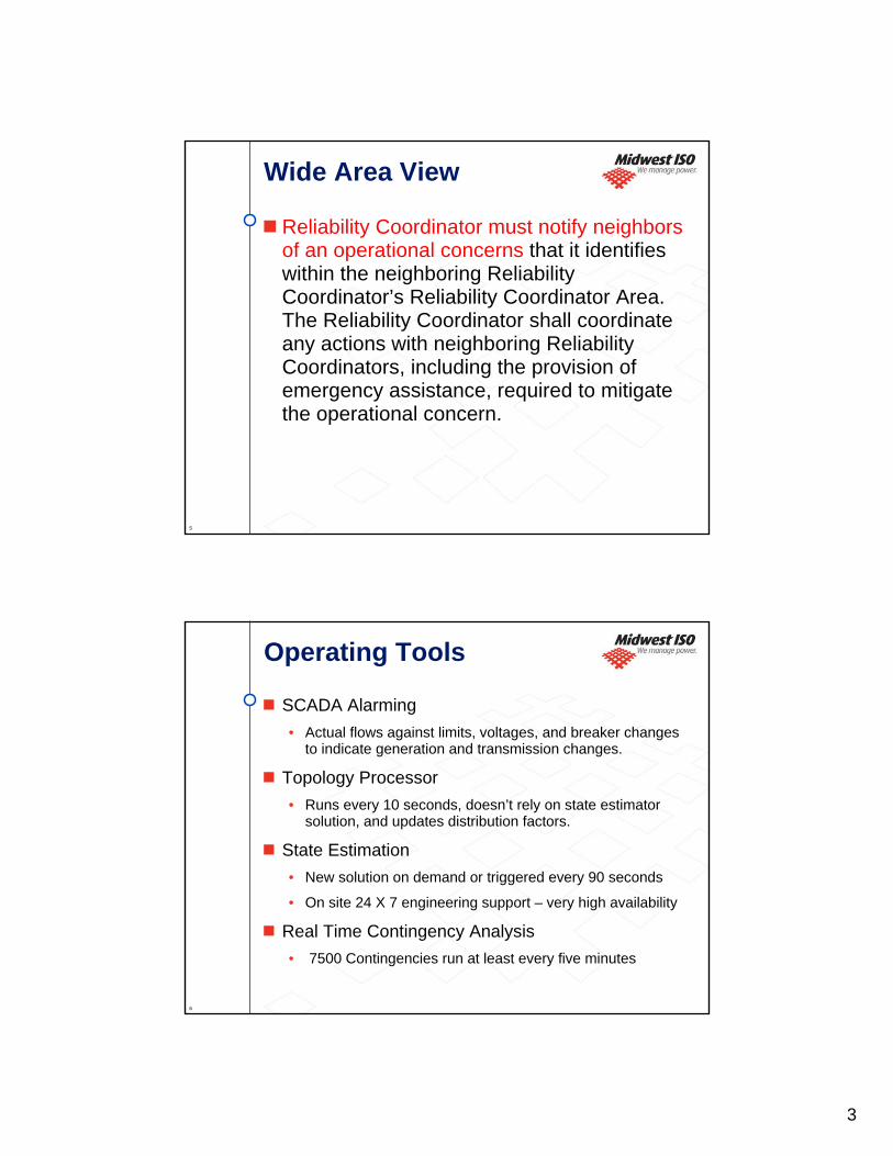
3
5
Wide Area View
Reliability Coordinator must notify neighbors of an operational concerns that it identifies within the neighboring Reliability Coordinator’s Reliability Coordinator Area. The Reliability Coordinator shall coordinate any actions with neighboring Reliability Coordinators, including the provision of emergency assistance, required to mitigate the operational concern.
6
Operating Tools
SCADA Alarming • Actual flows against limits, voltages, and breaker changes
to indicate generation and transmission changes.
Topology Processor• Runs every 10 seconds, doesn’t rely on state estimator
solution, and updates distribution factors.
State Estimation• New solution on demand or triggered every 90 seconds
• On site 24 X 7 engineering support – very high availability
Real Time Contingency Analysis• 7500 Contingencies run at least every five minutes

4
7
Operating Tools- SE Model
152883ICCP Total78573ICCP/Status74310ICCP/Analog
634393241Reactors494733591588CAPs898460432941XFMRs
1373626828369079Breakers/Sw303001723713063Lines254041461910786Loads465431381516Gen Units
307071787312834Buses20126113898737Substations
TotalExternalInternal
8
Processes
Outage maintenance Coordination
Next Day Security Analysis
Unit Commitment
Security Constrained Economic Dispatch
Redispatch
Switching
Load Reduction
5
9
Visualization
Visualization is required to help the Reliability Coordinator have situational awareness and assimilate large amount of information.
Need to leverage visualization to present operating tool results such that Reliability Coordinator can quickly understand and anticipate changes on the power system.
10
MISO RC Area

6
11 11
Video Wall
12
Carmel, Indiana
St. Paul, Minnesota

7
13
MISO Transmission Overview
14
MISO Transmission Overview (Legend)

8
15
16

9
17
18
10
19
Why CIM is Important
A Wide Area View without a correct model is a threat to reliability.
A Wide Area View without adequate real time data is of minimal value.
Model exchange on a timely basis provides a significant improvement in the tools available to RCs.
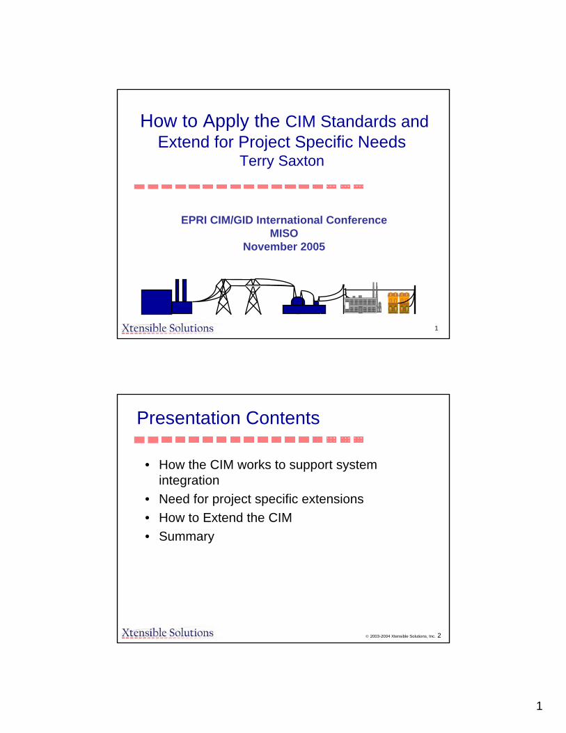
1
1
How to Apply the CIM Standards and Extend for Project Specific Needs
Terry Saxton
EPRI CIM/GID International Conference MISO
November 2005
© 2003-2004 Xtensible Solutions, Inc. 2
Presentation Contents
• How the CIM works to support system integration
• Need for project specific extensions• How to Extend the CIM• Summary
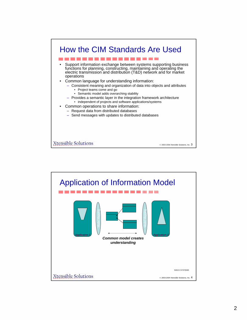
2
© 2003-2004 Xtensible Solutions, Inc. 3
How the CIM Standards Are Used
• Support information exchange between systems supporting businessfunctions for planning, constructing, maintaining and operating the electric transmission and distribution (T&D) network and for market operations
• Common language for understanding information:– Consistent meaning and organization of data into objects and attributes
• Project teams come and go• Semantic model adds overarching stability
– Provides a semantic layer in the integration framework architecture• independent of projects and software applications/systems
• Common operations to share information:– Request data from distributed databases– Send messages with updates to distributed databases
© 2003-2004 Xtensible Solutions, Inc. 4
Application of Information Model
SISCO SYSTEMS
Common model creates understanding
Application 1 Application 2
Mode
l Map
ping
Mode
l Map
ping

3
© 2003-2004 Xtensible Solutions, Inc. 5
“The building of the tower of Babel”by Pieter Bruegel, 1563Oil on oak panel, Kunsthistorisches Museum, Vienna
Inter-ApplicationIntegration SolutionsAlways ExperienceScaling ProblemsWithout ACommon LanguageFor InformationExchange
© 2003-2004 Xtensible Solutions, Inc. 6
CIM Provides Vocabulary -CIM XML Provides Standard Messages
• Webster’s Dictionary = CIM– Provides standard data semantics and data types
• Sentence structure = CIM- based XML messages– Just as you must have structured sentences to communicate orally,
you must have standard messages to share data electronically• Standard messages are needed to
– Ensure interoperability both within and between utilities– Remove seams– Define that part of CIM that must be supported by an application
• Adapters provide CIM <-> proprietary data mappings used by applications
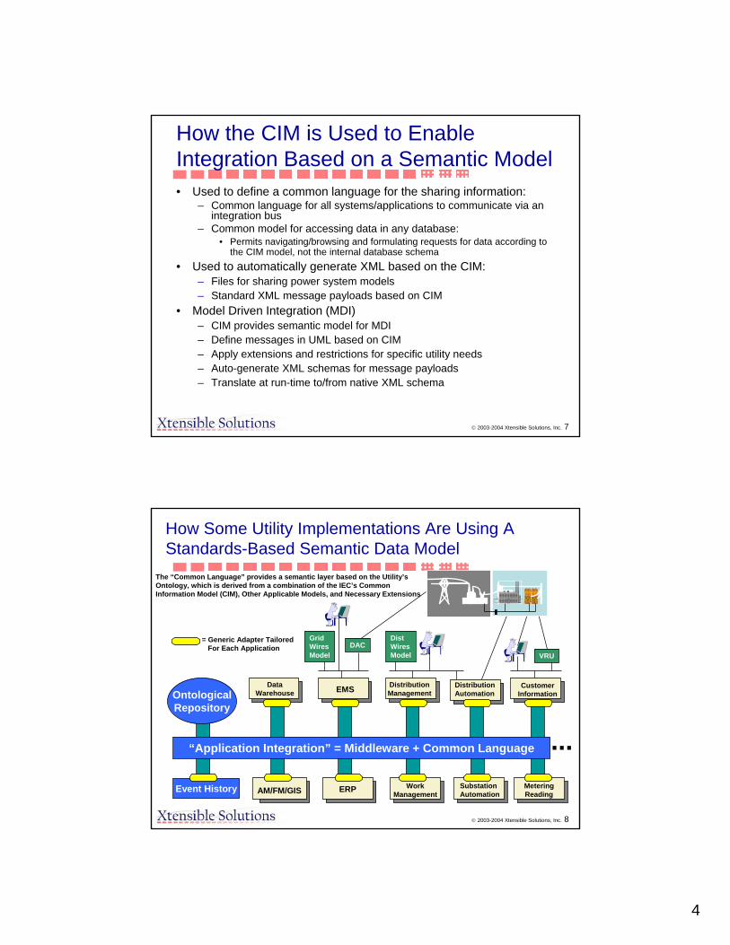
4
© 2003-2004 Xtensible Solutions, Inc. 7
How the CIM is Used to Enable Integration Based on a Semantic Model• Used to define a common language for the sharing information:
– Common language for all systems/applications to communicate via an integration bus
– Common model for accessing data in any database:• Permits navigating/browsing and formulating requests for data according to
the CIM model, not the internal database schema• Used to automatically generate XML based on the CIM:
– Files for sharing power system models – Standard XML message payloads based on CIM
• Model Driven Integration (MDI)– CIM provides semantic model for MDI– Define messages in UML based on CIM– Apply extensions and restrictions for specific utility needs– Auto-generate XML schemas for message payloads– Translate at run-time to/from native XML schema
© 2003-2004 Xtensible Solutions, Inc. 8
MeteringReading
SubstationAutomation
DistributionManagement
DistWiresModel
GridWiresModel
DAC
CustomerInformation
VRU
AM/FM/GIS
DistributionAutomation
ERP
DataWarehouse
“Application Integration” = Middleware + Common Language
OntologicalRepository
Event History WorkManagement
...
EMS
= Generic Adapter TailoredFor Each Application
How Some Utility Implementations Are Using AStandards-Based Semantic Data Model
The “Common Language” provides a semantic layer based on the Utility’sOntology, which is derived from a combination of the IEC’s CommonInformation Model (CIM), Other Applicable Models, and Necessary Extensions

5
© 2003-2004 Xtensible Solutions, Inc. 9
App CIMY.1 X.1Y.2 X.2Y.3 X.3Y.4 X.4Y.5 X.5
Publisher
Publishers:One Application Connector:•Obtains Data From Application And/Or Database•Transforms Data (if necessary) to the “CommonLanguage” (a Canonical Data Model)
•Puts Data Into Message Template•Publishes The Message (Fires & Forgets)
DataWarehouse
SubstationAutomation
OMS
DistWiresModel
GridWiresModel
DAC
CIS
VRU
AM/FM/GIS
DistributionAutomation
HumanResources
OutageReporting
Event History WorkManagement
EMS
...
CIMX.1 X.2 X.3 X.4 X.5
Subscriber
CIM AppX.1 B.1X.2 B.2X.3 X.4 X.5
Subscriber
CIM AppX.1 A.1X.2 X.3 X.4 A.4X.5 A.5
Subscriber
CIM AppX.1 C.1X.2 X.3 C.3X.4 C.4X.5
Subscriber
Subscribers:Several Application Adapters Receive The Same MessageEach Adapter:•Parses Message, Pulling Out Data Needed By Application•Transforms Data (if necessary) to Local Application Format•Passes Data To Local Application And/Or Database Through Most Appropriate Means
Message Type Instance: ChangedNetworkDataSet (Expressed In Common Language)
Decoupled InformationExchange
© 2003-2004 Xtensible Solutions, Inc. 9
© 2003-2004 Xtensible Solutions, Inc. 10
CIM for Information Exchange Between Enterprises• Possibility for common meaning and usage
across multiple enterprises– Ideal for inter-utility data exchange– Independence of protocol layer ensures stability and
needed flexibility to accommodate change and growth• Support transmission reliability
– Exchange of power system models between Security Coordinators based on CIM/XML
• Support market operations
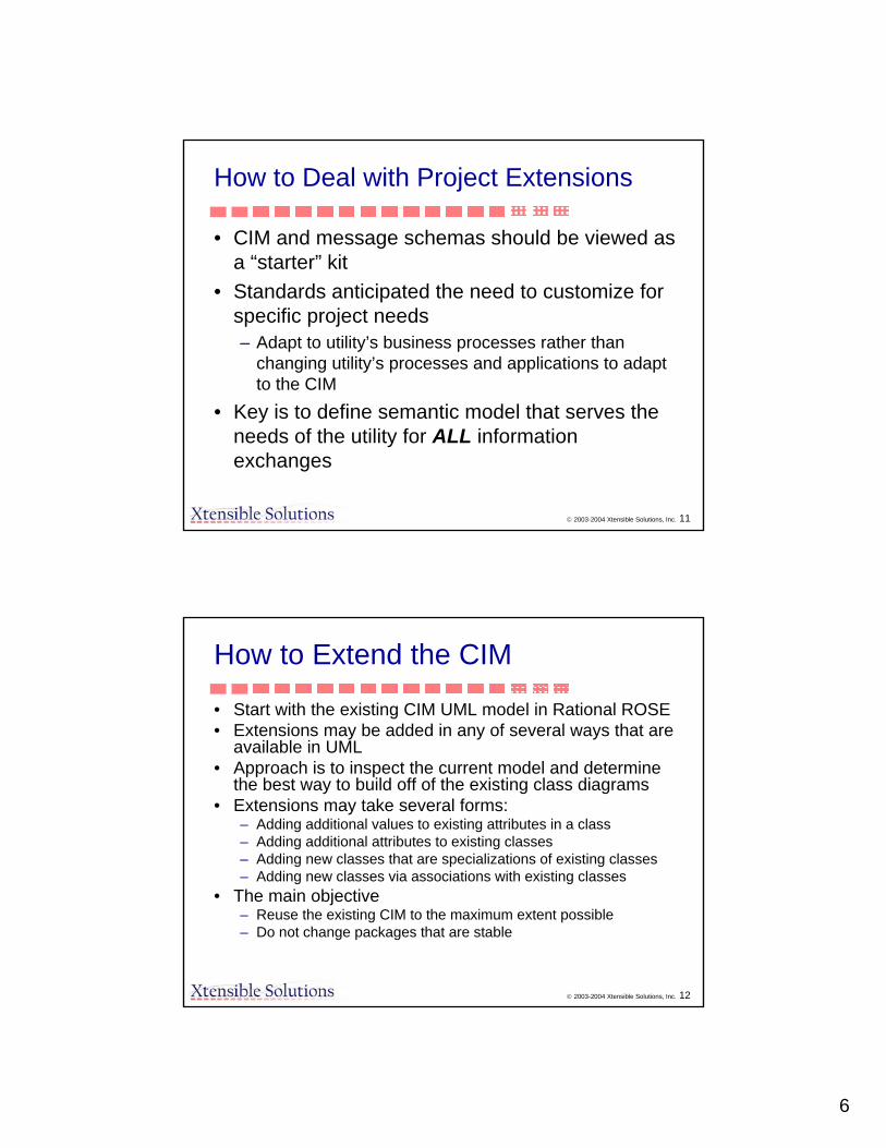
6
© 2003-2004 Xtensible Solutions, Inc. 11
How to Deal with Project Extensions
• CIM and message schemas should be viewed as a “starter” kit
• Standards anticipated the need to customize for specific project needs– Adapt to utility’s business processes rather than
changing utility’s processes and applications to adapt to the CIM
• Key is to define semantic model that serves the needs of the utility for ALL information exchanges
© 2003-2004 Xtensible Solutions, Inc. 12
How to Extend the CIM
• Start with the existing CIM UML model in Rational ROSE• Extensions may be added in any of several ways that are
available in UML• Approach is to inspect the current model and determine
the best way to build off of the existing class diagrams• Extensions may take several forms:
– Adding additional values to existing attributes in a class– Adding additional attributes to existing classes– Adding new classes that are specializations of existing classes– Adding new classes via associations with existing classes
• The main objective– Reuse the existing CIM to the maximum extent possible– Do not change packages that are stable
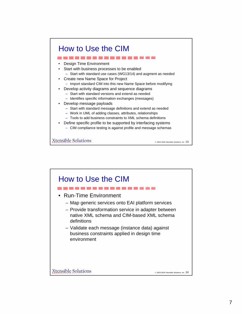
7
© 2003-2004 Xtensible Solutions, Inc. 13
How to Use the CIM
• Design Time Environment• Start with business processes to be enabled
– Start with standard use cases (WG13/14) and augment as needed• Create new Name Space for Project
– Import standard CIM into this new Name Space before modifying• Develop activity diagrams and sequence diagrams
– Start with standard versions and extend as needed– Identifies specific information exchanges (messages)
• Develop message payloads– Start with standard message definitions and extend as needed– Work in UML of adding classes, attributes, relationships– Tools to add business constraints to XML schema definitions
• Define specific profile to be supported by interfacing systems– CIM compliance testing is against profile and message schemas
© 2003-2004 Xtensible Solutions, Inc. 14
How to Use the CIM
• Run-Time Environment– Map generic services onto EAI platform services– Provide transformation service in adapter between
native XML schema and CIM-based XML schema definitions
– Validate each message (instance data) against business constraints applied in design time environment
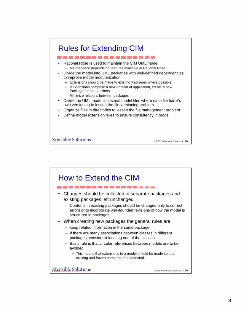
8
© 2003-2004 Xtensible Solutions, Inc. 15
Rules for Extending CIM
• Rational Rose is used to maintain the CIM UML model– Maintenance depends on features available in Rational Rose
• Divide the model into UML packages with well-defined dependencies to improve model modularization– Extensions should be made to existing Packages where possible– If extensions comprise a new domain of application, create a new
Package for the additions– Minimize relations between packages
• Divide the UML model in several model files where each file has it's own versioning to lessen the file versioning problem
• Organize files in directories to lessen the file management problem• Define model extension rules to ensure consistency in model
© 2003-2004 Xtensible Solutions, Inc. 16
How to Extend the CIM
• Changes should be collected in separate packages and existing packages left unchanged.– Contents in existing packages should be changed only to correct
errors or to incorporate well-founded revisions of how the model is structured in packages
• When creating new packages the general rules are– keep related information in the same package– If there are many associations between classes in different
packages, consider relocating one of the classes– Basic rule is that circular references between models are to be
avoided• This means that extensions to a model should be made so that
existing and frozen parts are left unaffected.

9
© 2003-2004 Xtensible Solutions, Inc. 17
How to Extend the CIM
• The techniques for extensions: – Extensions (new attributes or associations) are placed
in new classes that specialize existing classes using inheritance
– Extensions are placed in new packages separate from the existing packages
• Extensions are only loaded when needed for application
– If existing classes are extended with new associations, the associations should be added to the new package
© 2003-2004 Xtensible Solutions, Inc. 18
MDI Summary
• Builds on industry standards.• Leverages best practice integration architecture frameworks.• Provides:
– One integrated methodology– One set of integrated tools– One enterprise integration semantic model– One enterprise reuse repository for: business processes, services,
messages, key information assets (bundling of data, message, & service), and application connectivity.
• Is a complete and standards based design time solution from top to bottom (from processes all way to applications), and can be built upon many different integration platforms for run time.
• Builds the foundation for a service-oriented and event-driven business integration infrastructure.
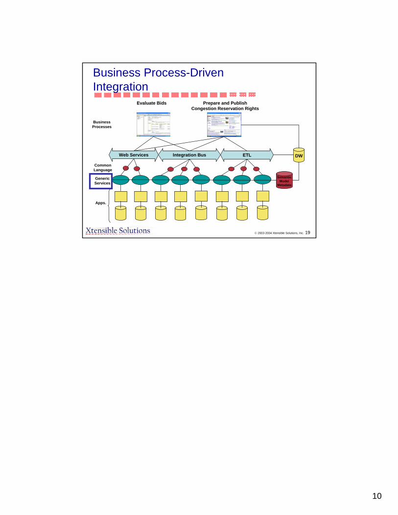
10
© 2003-2004 Xtensible Solutions, Inc. 19
ETLIntegration BusWeb Services
Apps.
GenericServices
Evaluate Bids
DW
Prepare and PublishCongestion Reservation Rights
CommonLanguage
SemanticModel
Metadata
Business Process-Driven Integration
Business Processes
1
PTD Energy Management & Information Systems
CIM Maintenance and Version Management
Kurt Hunter
Siemens Power Transmission & Distribution, Inc.Energy Management & Automation
08-1-2005 2
What is the CIM standard?
Series of IEC standards all using the same Common Information Model
61850 – Substation Automation61968 – Distribution Management System61970 – Energy Management System

2
Siemens Power Transmission & Distribution, Inc.Energy Management & Automation
08-1-2005 3
What is the CIM standard?
Standards developed by Working Groups under IEC Technical Committee 57 (TC57)
WG10, WG11, WG12 – Substation AutomationWG13 – Energy Management System Application Program
InterfaceWG14 – Distribution Management System InterfacesWG16 – Deregulated Electricity Market CommunicationsWG19 - Harmonization
Siemens Power Transmission & Distribution, Inc.Energy Management & Automation
08-1-2005 4
What is the CIM standard?
WG’s responsible for different portions of the CIM
CIM divided into packages, which are maintained independently
WG19 handles areas of overlap between WGs

3
Siemens Power Transmission & Distribution, Inc.Energy Management & Automation
08-1-2005 5
Current WG13 CIM Maintenance Process
Issues List
Issues received from:WG membersNational Comments (from standardization voting process)Interoperability TestsIndividuals working with CIM
Issues Addressed In Order ReceivedWG meetingsConference Calls
Siemens Power Transmission & Distribution, Inc.Energy Management & Automation
08-1-2005 6
Current WG13 CIM Maintenance Process
Sample Issue ListIssue No.
Source Date Clause / Subclause /Paragraph/Figure / Table
COMM ENTS Proposed change Decis ion Person Assigned
Due Date Status
19 Magnus J 00-11-28 The ConductingEquipments has a 0..* relation to Terminal meaning that any number of terminals might be attached to a ConductingEquipment. How ever, all equipment do have a w ell specif ied number of terminals, e.g. Sw itch has tw o, Conductor has tw o, Connecto
Make the number of terminal explicit for each type.
WG13: Terminals attribute deleted f rom ConductingEquipment. Table of required number of terminals for each equipment type w ill be added to Part 301. Erich w ill prepare table for review
Complete (See Issue 87)
59 Magnus J 1/31/01 Additional properties slope and voltageSetPoint for SVC is needed.
WG13: Agree to add slope and voltageSetPoint to StaticVARCompensator (type undetermined). Lars to ask Magnus to determine type. 3/12 - voltageSetPoint - voltage, Slope - perunit per kvolts base MVAR
Complete
204 L. Osterland/H. Diehl
6/22/04 Part 301 Need to explain situations w here there are multiple possible parents w here at least one parent is mandatory (e.g., Bay may be a child to either Substation or VoltageLevel).
Add text to Part 301 Open. Deferred to PL on Equipment/Naming hierarchies

4
Siemens Power Transmission & Distribution, Inc.Energy Management & Automation
08-1-2005 7
Current WG13 CIM Maintenance Process
Issue Resolutions Implemented by volunteersModel Versions Maintained using Groove
Siemens Power Transmission & Distribution, Inc.Energy Management & Automation
08-1-2005 8
Current WG13 CIM Maintenance Process
Three Stages of Model Development
Standard (Released and Frozen)
Release Candidate
Project (Working Model)
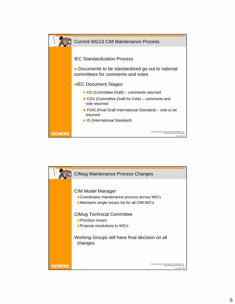
5
Siemens Power Transmission & Distribution, Inc.Energy Management & Automation
08-1-2005 9
Current WG13 CIM Maintenance Process
IEC Standardization Process
Documents to be standardized go out to national committees for comments and votes
IEC Document Stages
CD (Committee Draft) – comments returned
CDV (Committee Draft for Vote) – comments and vote returned
FDIS (Final Draft International Standard) – vote to be returnedIS (International Standard)
Siemens Power Transmission & Distribution, Inc.Energy Management & Automation
08-1-2005 10
CIMug Maintenance Process Changes
CIM Model ManagerCoordinates maintenance process across WG’sMaintains single issues list for all CIM WG’s
CIMug Technical CommitteePrioritize issuesPropose resolutions to WG’s
Working Groups still have final decision on all changes
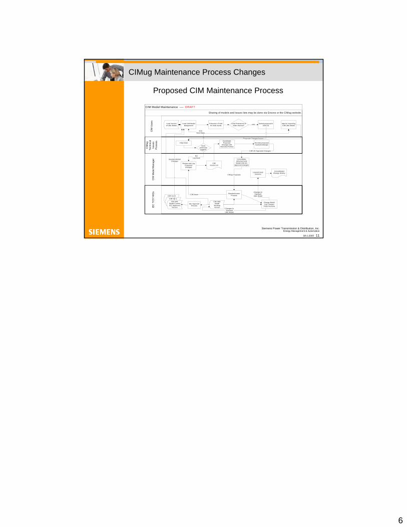
6
Siemens Power Transmission & Distribution, Inc.Energy Management & Automation
08-1-2005 11
CIMug Maintenance Process Changes
Proposed CIM Maintenance Process
CIM Ver-0
CIM Ver-1
Sharing of models and issues lists may be done via Groove or the CIMug website.
CIM Model Maintenance ---- DRAFT
CIM
ug
Tech
nica
l Is
sues
P
roce
ssC
IM M
odel
Man
ager
IEC
TC
57 W
Gs
CIM
Use
rs
Local Version of UML Model
Extension of CIMfor local needs
Submit proposal to CIM UG
Local Extensions of wider Interest? YES
Develop proposed resolution/design
Idea for improving CIM UML Model
Proposed Changes/Issues
CIM UG Approved Changes
StandardizationProcess
CIMug Proposals
CIM UML Model
Working Version
Change ModelLog Changes
Track Versions
Review and Log Proposed Changes
Coordinate Proposed
Changes with interested Parties
Log and track versions
Changes to Standard
UML Model
NOLog Issue
Consolidate, document and Model CIM UG
approved changes
Standard Model Changes
Changes to Standard
UML Model
Local CIM Model Mangement
CIMIssues List
Issue previously logged?
YESSend Back
CIM Issue
ConsolidatedChange History
CIM UML Model CurrentIEC Approved
Version
Help Desk
IEC Approval Process
The Common Information Model as a Software Framework
Alan McMorran
Introduction
• The CIM Java Framework
• The Origin and Model classes
• The Model Library
• Mercury - a CIM Power Systems Toolkit
• CIM Network Model Creator
• Model Visualisation
• Network Model Integration
• Model Exporting
• Future Avenues of Research

Beyond Translation
CIM
Power System Application
Translator
Power System Application
Translator
EMS
Translator
EMS
Translator
Beyond Translation
CIM
Power System Application
Power System Application
EMS
Translator
EMS
Translator
Beyond Translation
• Currently the CIM is primarily used for exchanging data between EMS systems
• This requires data to be translated to and from an application’s own internal data format and the CIM
• The Object-Oriented design of the CIM standard raises the possibility of it being used as a software framework
CIM Java Framework
• The CIM Class structure can be mapped to almost any Object-Oriented language
• Java was chosen for its cross-platform compatibility and flexibility
• The same modules can be used for CLI applications, Applets and Servlets

CIM Java Framework
• The CIM UML model was converted to native Java classes requiring only minimal changes
• Basic methods were created to modify the attributes and associations within an object
• This provided a mechanism for storing and extracting CIM data as Java objects
CIM Java Framework
• The hierarchy was modified with the addition of a single Origin class from which all other CIM classes inherit
Origin
BasePowerNaming BaseVoltage
PowerSystemResource
Equipment EquipmentContainer
The addition of this class allows common methods to be added to all CIM Objects e.g. getXML(), getUri()

CIMObject
CIMObject CIM
Object
CIMObject
CIMObject
CIMObject
CIMObject
CIMObject
CIMObject
CIMObject
CIM Java Framework
• A new Model class was created to contain power system models instantiated as CIM Java Objects
• The ModelFactory class imports and converts CIM XML files into these self-contained CIM Java Models
ModelFactory
CIMXML
Model
CIM Java Framework
• The Model class API contains methods for exporting and interrogating the CIM power system model
• The API includes methods to:
• Export the model as full CIM XML
• Add, remove and update objects within the model
• Create Topological Nodes
• Validate the topological integrity
• Return a copy of the model as a new, separate Model instance
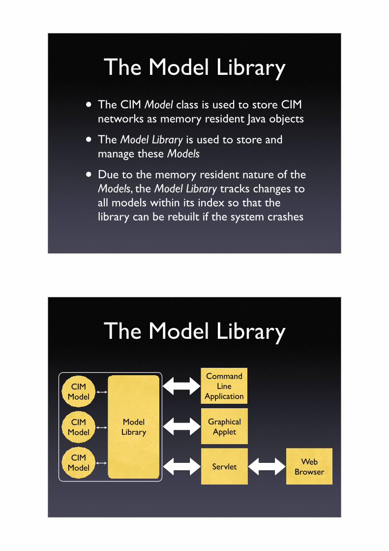
The Model Library
• The CIM Model class is used to store CIM networks as memory resident Java objects
• The Model Library is used to store and manage these Models
• Due to the memory resident nature of the Models, the Model Library tracks changes to all models within its index so that the library can be rebuilt if the system crashes
The Model Library
CommandLine
Application
ModelLibrary
CIMModel
CIMModel
CIMModel Servlet
GraphicalApplet
Web Browser

The Model Library
ModelLibrary
CIMModel
CIMModel
CIMModel Servlet
Web Browser
Mercury
ServletWeb
Browser
• Mercury is a Power Systems toolkit based on the CIM Java Framework with a Rich Web Application front end
• The toolkit runs under Apache Tomcat on the server side and requires only a web browser on the client side

Network Model Maintenance
• Allows the user to view and edit CIM Power System Models
• Modify attributes and associations
• Create new network objects
• View the model in Bus-Branch format
• Uses AJAX to provide an desktop-application like environment on the Web

Network Model Creation
• Create new CIM Power System Models with a graphical point and click interface
• Save the model layout to edit and modify at a later time
• Uses background server communications to create the CIM objects in the library
• Can be expanded to use future CIM Extensions with only minor modifications

Network Model Integration

Network Model Integration
Network Model Integration
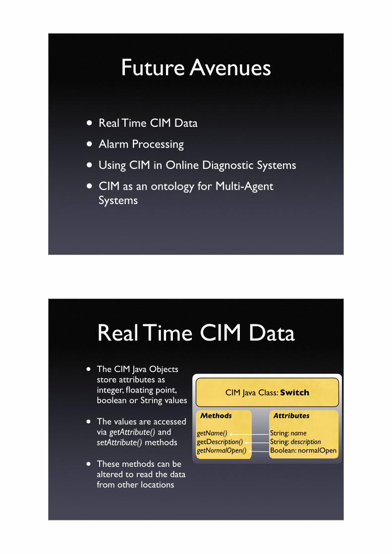
Future Avenues
• Real Time CIM Data
• Alarm Processing
• Using CIM in Online Diagnostic Systems
• CIM as an ontology for Multi-Agent Systems
Real Time CIM Data
• The CIM Java Objects store attributes as integer, floating point, boolean or String values
• The values are accessed via getAttribute() and setAttribute() methods
• These methods can be altered to read the data from other locations
Attributes
String: nameString: descriptionBoolean: normalOpen
Methods
getName()getDescription()getNormalOpen()
CIM Java Class: Switch

Real Time CIM Data
• The CIM Java Objects store attributes as integer, floating point, boolean or String values
• The values are accessed via getAttribute() and setAttribute() methodmethods
• These methods can be altered to read the data from other locations
Attributes
String: nameString: description
Methods
getName()getDescription()getNormalOpen()
CIM Java Class: Switch
SCADA Interface Object
getSwitchStatus()
Realtime SCADA Data
switchStatus
Network
Model
Control Centre Diagnostic Systems
Alarm Processing
CIM
Fault DiagnosisEMS
Translator

Online Diagnostic Systems
Protection Scheme
Network Topology
Protection Diagnostics
CIM Extensions
SCADA
DFR
Protection Scheme
Network Topology
Protection Diagnostics
SCADA
DFRAlarm
Processing
Fault Diagnosis
CIM Applications
CIM
Power System App.
EMS
Translator
Model Library
Translator
Extensions

Agent
AgentAgent
Agent Agent
Agent
Agent
Agent
Agent
CIM as an Agent Ontology
Protection Scheme
Protection Diagnostics
SCADA
DFRAlarm
Processing
Fault Diagnosis
Power System App.
Model Library
Condition Monitoring
CIMCIM
CIM
CIM
CIM
CIM
CIM
CIM
CIM
Summary
• The CIM offers a powerful foundation for creating Power System applications
• Enhancements to the CIM Standard can be integrated into the framework with minimal modification
• Embedding functionality within the CIM Classes provides a powerful API on which applications can be built

Summary
• Example applications already implemented include the Model Library, Network Creator, Model Integrator, Bus-Branch conversion and Model Visualisation
• Future research will focus on extending and enhancing the Mercury Toolkit’s suite of applications and integrating it with existing Power System Applications

CIM/GID Unified Data Model at LIPA for the Enterprise
EPRI LIPA- Raymond Lings - Mike Hervey- Bhavin Desai - Ron Clare
- Joe Odierna- Richie Soper- Steve Wasylenko- Brigitte Wynn
Presented at:EPRI CIM/GID International Conference
Midwest ISOCarmel, Indiana, USA
2
Traditional Data Warehouse
AMS/WMS OMS ArchiveEMS
Proprietary Connector
Proprietary Connector
Proprietary Connector
Proprietary Connector
Data Warehouse
Users query the warehouse to discover current conditions and trends
Data Analysis/ Presentation
Data Mart
Data Analysis/ Presentation
Data Mart
Data Analysis/ Presentation
Data Mart
Proprietary connectors are very expensive to develop
and maintain as well as tied to one vendor’s
technology.
Proprietary Connector
LIPA Back End Data Bases

3
CIM/GID Data Warehouse
AMS/WMS OMS ArchiveEMS
CIM/GID CIM/GID CIM/GIDCIM/GID
Data WarehouseEmploys CIM (schema not
optimized for any single application).
Wrappers can be supplied off the shelf.
Data Analysis/ Presentation
Data Mart
Data Analysis/ Presentation
Data Mart
Data Analysis/ Presentation
Data Mart
Employ denormalized CIM (schema optimized for a
single application).
Wrapper can be supplied off the shelf.
CIM/GID
The CIM standardizes the “what”. The GID standards the “how”
4
Intended Vision for EPRI’s CIM/GID Virtual Data Warehouse
AMS/WMS OMS ArchiveEMS
Users can selectively cache at this layer using GDA Aggregator/Cache. Caching here decouples user
queries from critical real time application processing.
MMW MMW MMW
User can selectively cache information at this layer using “Cached Queries”
DB Client AdapterWith Cache
DB Client AdapterWith Cache
DB Client AdapterWith Cache
DB Server AdapterWith Cache
CIM/GID CIM/GID CIM/GIDCIM/GID
CIM/GIDEPRI-SISCO
Virtual Data Warehouse(VDW) Technology
SISCO UIBTechnology
Not all data needs to be copied

5
Potential Benefits
• Non intrusive integration of data from existing databases– Wraps legacy databases with CIM compliant GDA interface– Application adapters can be supplied off the shelf
• EMS Systems• Database Systems• Potential exists for additional standard adapters to be developed
• Open standards based architecture– Components interconnect using standard services– Enables best of breed use of tools– Puts vendors on a level playing field– Enables 3rd party deployment
• Support standard database/data mining clients – Supports ODBC clients
• Deployment flexibility– Not all data not necessarily duplicated in cache
• Enables more up to date data– Data from a message bus and legacy databases can be joined – Standards support updating data in cache as data changes in legacy systems and databases
• Not available yet in VDW, but system is evolving in this direction
6
Current LIPA Project Status
– Proof of concept test conducted to verify CIM/GID Virtual Data Warehouse concept (shown in slide # 2).– To verify this concept EPRI Maintenance Management Workstation (MMW) was installed and integrated
with the CIM/GID Virtual Data Warehouse.– Key challenges
• Data Engineering, • Up-front buy-in & Process Consistency.
– Understanding what you have? - Understanding your legacy databases and how they relate to each other
– Understanding the Common Information Model– Mapping
– A sample set of 5 business applications were used to verify that queries that ran within these business applications successfully returned data
– These queries were written to retrieve data from CIM data fields and return results– As part of this test the following components were also installed and used:
• VDW Database Client Adapter• VDW Database Servers Adapter installed
– During this test the following issues were noted:• Backward compatibility issues – e.g. different instances of Oracle used in laboratory test versus
proof of concept test environment.• Overall Performance without any caching
– Query Run Times – time taken to return data sometimes significantly more than “traditional environment”.
• Above noted issues require diligent solutions and careful thought process moving forward.• As follow up, a 2 day brainstorm session was held as follow up during first week of October 2005.

7
Critical Next Steps: A Transition to fully operational VDW and UIB
• In-house and production testing to conformance.• Implement remaining MMW business applications –a mix of those that need aggregator and non-aggregator data (13 in total).
• Data mapping between PSS/ODMS and MMW– Full scale conformance testing– Industry wide buy-in and support of concept.– The infrastructure to test this approach between
two utilities.
8
– Improve performance • Ultimate objective – query run time should be
comparable to “Traditional Environment” settings• Steps to accomplish objective/goal – 2006
activities– Implement selective Database Server Adapter
caching (cache at the middle “data warehouse”level)
– Implement selective Database Client Adapter caching (cache at the top “data mart” level)
Critical Next Steps: A Transition to fully operational VDW and UIB

9
The Ultimate Vision for LIPA and the utility community – Long Term
• A risk management platform consists of– A Data Integration Infrastructure,– Automated analysis of integrated views from operational, asset and energy market
information.
• The VDW currently integrates asset and operational data.
• Inclusion of energy market data in the VDW would allow a risk management application to get a unified view of required data
• Hence, the ultimate vision/goal lies in achieving the ability to apply integrated data management philosophy for an Enterprise wide Risk Assessment approach.– To Analyze Potential Returns or Losses Associated With The Operation Of Utility
Assets – Quantitative analysis which combines financial information and asset data to allow
for• Return of Investment analysis• Address Aging Infrastructure Issues• Continuous risk and performance assessment using asset and operational data
10
Contact Details
From Long Island Power Authority
• Mike Hervey• Ron Clare• Joe Odierna• Rich Soper• Steve Wasylenko• Brigitte WynnFrom The Electric Power Research Institute• Raymond Lings, Area Manager, Transmission & Distribution
– [email protected], 650-855-2177.• Bhavin Desai, Project Manager, Substations Maintenance Optimization
– [email protected], 704-717-6463.

0EPRI CIM/GID International Conference November 2, 2005
• The objective of this present is to share SCE’s experience to implement IEC TC 57 WG14 CIM with the CIM user community, other utilities and CIM work group members.
• The presentation is focused more on CIM implementation environment at SCE, i.e. applications to be integrated and methodology used for the CIM implementation.
EPRI CIM/GID International Conference
Southern California Edison (SCE)Southern California Edison (SCE)Experience with CIM (IEC TC57 WG 14Experience with CIM (IEC TC57 WG 14 )
Taka Kikkawa
November 2, 2005November 2, 2005

1EPRI CIM/GID International Conference November 2, 2005
1SCE Experiences with CIM November 2, 2005EPRI CIM/GID International Conference
Presentation ContentsPresentation Contents
• CIM implementation history – Key projects
• Current CIM implementation projects – Examples
• CIM implementation results – Observation, lessons learned
• Current challenges – Enterprise approach, Harmonization
• Suggestions – CIM User Group, Work Group
The characteristic of CIM implementation at SCE to date is “evolutionary” and “project based.
CIM implementation history shows these characteristics.
Current CIM implementation projects present SCE’s intention to use Model Driven Integration approach.
CIM implementation results summarizes lesson learned and some observations.
Current challenges present SCE’s attempt to (a) CIM implementation at Enterprise Level (b) Harmonization with other CIM specifically with ERP
SCE’s suggestions for CIM activities to CIM Working Groups and User Community.

2EPRI CIM/GID International Conference November 2, 2005
2SCE Experiences with CIM November 2, 2005EPRI CIM/GID International Conference
History History -- Key ProjectsKey Projects
• 1999 : Integration BUS (IBUS) Project – Integrated Power Management System (PMS) and Outage Management System ( OMS)
• 2001: Work Management System (WMS) Project – Used CIM messages to exchange asset data between New Construction WMS and Maintenance & Inspection WMS
• 2002: OMS Project – Utilized the messages (asset data) available in IBUS and also used XML with DTD.
• 2004: Ledger Accounting System (LAS) Project – Created CIM messages based on the CIM UML and utilized XML schema.
• 2005: Distribution Service & Pricing (DSRP) Project – Used MDI Workbench to manage CIM UML and automatically generate CIM messages
SCE’s CIM implementation is project based.
These are key projects for CIM implementation.
Note that SCE’s experience to date is mostly in the Distribution Management space i.e. IEC TC57 WG14 subject area, (IEC 61968)
Significance of LAS and DSRP projects are to apply Model Driven Integration approach introduced to SCE by Xtensible Solutions.
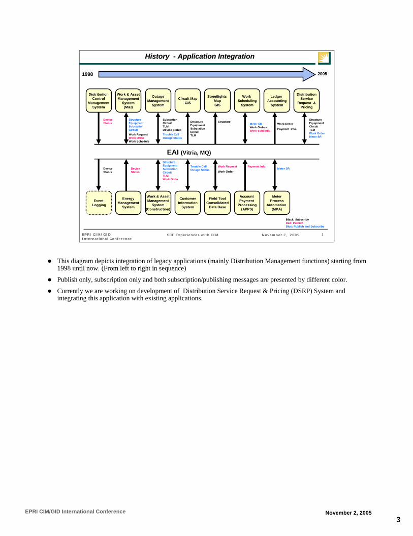
3EPRI CIM/GID International Conference November 2, 2005
3SCE Experiences with CIM November 2, 2005EPRI CIM/GID International Conference
EventLogging
DistributionControl
ManagementSystem
Work & AssetManagement
System(M&I)
Work & AssetManagement
System(Construction)
OutageManagement
System
Circuit MapGIS
CustomerInformation
System
Streetlights MapGIS
Field ToolConsolidated
Data Base
EAI (Vitria, MQ)
20051998
EnergyManagement
System
Device Status
Device Status
Structure EquipmentSubstationCircuit
Structure EquipmentSubstationCircuitTLMWork Order
SubstationCircuitTLMDevice Status
Work Request
Work Order
Work RequestWork OrderWork Schedule
Structure
Device Status
Structure EquipmentCircuitTLMWork OrderMeter SR
Trouble CallOutage Status
Trouble CallOutage Status
Black: SubscribeRed: PublishBlue: Publish and Subscribe
Work Scheduling
System
Meter SRWork OrdersWork Schedule
Account Payment
Processing(APPS)
MeterProcess
Automation (MPA)
Ledger Accounting
System
Payment Info.
Work Order
Payment Info.
Meter SR
History History -- Application IntegrationApplication Integration
DistributionService
Request &Pricing
StructureEquipmentSubstationCircuitTLM
This diagram depicts integration of legacy applications (mainly Distribution Management functions) starting from 1998 until now. (From left to right in sequence)
Publish only, subscription only and both subscription/publishing messages are presented by different color.
Currently we are working on development of Distribution Service Request & Pricing (DSRP) System and integrating this application with existing applications.
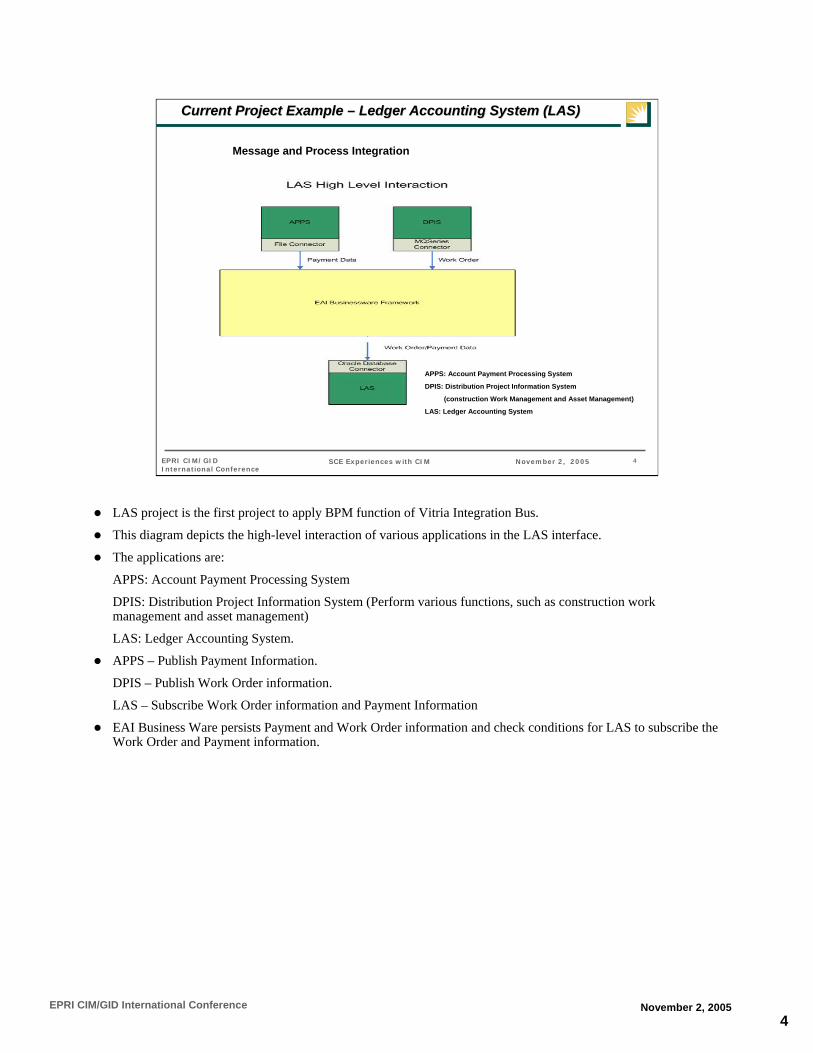
4EPRI CIM/GID International Conference November 2, 2005
4SCE Experiences with CIM November 2, 2005EPRI CIM/GID International Conference
Current Project Example Current Project Example –– Ledger Accounting System (LAS)Ledger Accounting System (LAS)
Message and Process Integration
APPS: Account Payment Processing System
DPIS: Distribution Project Information System
(construction Work Management and Asset Management)
LAS: Ledger Accounting System
LAS project is the first project to apply BPM function of Vitria Integration Bus.
This diagram depicts the high-level interaction of various applications in the LAS interface.
The applications are:
APPS: Account Payment Processing System
DPIS: Distribution Project Information System (Perform various functions, such as construction work management and asset management)
LAS: Ledger Accounting System.
APPS – Publish Payment Information.
DPIS – Publish Work Order information.
LAS – Subscribe Work Order information and Payment Information
EAI Business Ware persists Payment and Work Order information and check conditions for LAS to subscribe the Work Order and Payment information.

5EPRI CIM/GID International Conference November 2, 2005
5SCE Experiences with CIM November 2, 2005EPRI CIM/GID International Conference
Current Project Example Current Project Example –– Ledger Accounting System (LAS)Ledger Accounting System (LAS)
Conceptual CIM Message Flow
This is CIM message flow architecture.
Enterprise applications are DPIS, APPS and LAS in the previous slide.
Connectors are File Connector, MQSeries Connector and Oracle Database connector in the previous slide.
CIM message transformation and message persist are performed in the EAI Businessware Framework.

6EPRI CIM/GID International Conference November 2, 2005
6SCE Experiences with CIM November 2, 2005EPRI CIM/GID International Conference
Current Project Example Current Project Example –– Ledger Accounting System (LAS)Ledger Accounting System (LAS)
DPIS and APPS publish Work Order and Payment Messages to the EIA layer and are then subscribed by LAS
The sequence diagram depicts the flow of events between DPIS, LAS and EAI layer (Vitria).
The two applications namely DPIS and APPS publishes Work Order and Payment Messages to the EAI layer and are then subscribed by LAS.
The EAI layer persists these messages and identify a payment with associated work order. When association is found the Work Order Message and the Payment Message are sent to LAS.

7EPRI CIM/GID International Conference November 2, 2005
7SCE Experiences with CIM November 2, 2005EPRI CIM/GID International Conference
Current Project Example Current Project Example –– Ledger Accounting System (LAS)Ledger Accounting System (LAS)
This is the UML based logical information model for the LAS Project.
Note that classes from WG 14 CIM and ERP CIM (which was provided by MDI workbench) and SCE extension.
LAS Project is to interface with financial applications, ERP classes became important entities.
Customer Class: Since customer data is not on the current SCE Integration Bus (IBUS), the Work Order message include customer information.
Work Indicators class: This is SCE extension class in which many DPIS specific information are capture and used by LAS.
Due to the project constraints, we could not modify the LAS application to process CIM based message. We created SCE extension to handle legacy application specific attributes for now. In the future we’d like to update legacy applications to be able to process CiM based messages.

8EPRI CIM/GID International Conference November 2, 2005
8SCE Experiences with CIM November 2, 2005EPRI CIM/GID International Conference
Current Project Example Current Project Example –– Ledger Accounting System (LAS)Ledger Accounting System (LAS)
Results:Generation of CIM messages based on UML based Information Model was very effective by using the MDI Workbench (TranslationUML to XML message schema)
“Customer” object is not available on the EAI Integration Bus (IBUS). Therefore, Work Order message carry all attributes of customer information and result in:
(a) Work Order message become lengthy – performance & storage impact
(b) Questionable reusability of the message
This is a draw back of project based application integration. Needfor application integration road map (i.e. Enterprise view).
“WorkIndicator” (SCE Extension) class includes physical attributes specific to DPIS and LAS. Due to the project schedule/budget, modification of LAS application logic to process normalized CIM message could not be done.
The first bullet is a very positive experience.
The second and the third bullet are the results of “Project Based” application integration and associated CIM implementation effort.
XML message design have impact on performance and storage requirements. For this project, due to the project constraints, the Work Order message became very long and experienced negative impact.
In the SCE environment and may be in other utilities this is always the issue we need to deal with.
However, the third bullet is not totally negative result. We isolated the problem and the applications could be modified in the future to process CIM messages.

9EPRI CIM/GID International Conference November 2, 2005
9SCE Experiences with CIM November 2, 2005EPRI CIM/GID International Conference
Current Projects Current Projects –– Distribution Service Request & Pricing (DSRP)Distribution Service Request & Pricing (DSRP)
Distribution Service Request & Pricing (DSRP) System is being developed internally by SCE which provided us more flexibility for designing CIM messages.
This diagram depicts five enterprise applications interfacing to DSRP via the EAI layer.
Note that many messages are passed between DSRP and EAI. EAI layer maintains status which are used to execute various DSRP components to satisfy Business Process requirements.
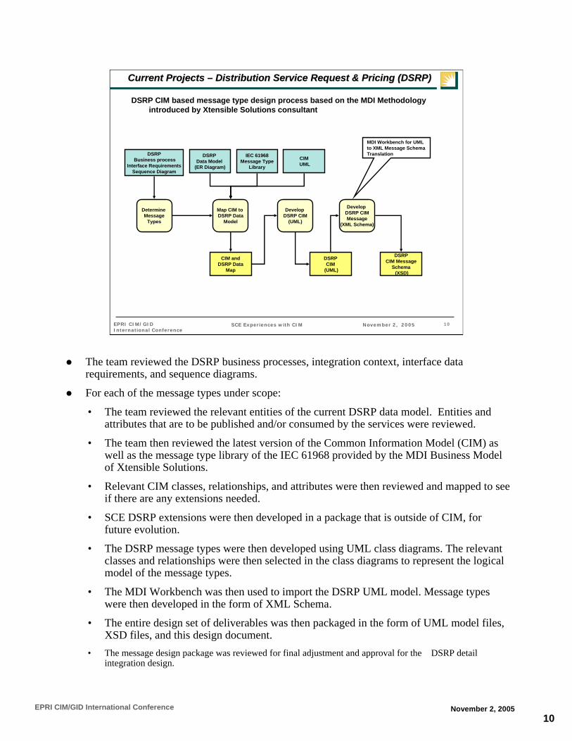
10EPRI CIM/GID International Conference November 2, 2005
10SCE Experiences with CIM November 2, 2005EPRI CIM/GID International Conference
Current Projects Current Projects –– Distribution Service Request & Pricing (DSRP)Distribution Service Request & Pricing (DSRP)
DSRP CIM based message type design process based on the MDI Methodology introduced by Xtensible Solutions consultant
Determine Message
Types
DSRPBusiness process
Interface RequirementsSequence Diagram
DSRP Data Model
(ER Diagram)
Map CIM to DSRP Data
Model
CIMUML
IEC 61968Message Type
Library
Develop DSRP CIM
(UML)
Develop DSRP CIMMessage
(XML Schema)
DSRPCIM
(UML)
CIM andDSRP Data
Map
DSRPCIM Message
Schema(XSD)
MDI Workbench for UML to XML Message Schema Translation
The team reviewed the DSRP business processes, integration context, interface data requirements, and sequence diagrams.
For each of the message types under scope:
• The team reviewed the relevant entities of the current DSRP data model. Entities and attributes that are to be published and/or consumed by the services were reviewed.
• The team then reviewed the latest version of the Common Information Model (CIM) as well as the message type library of the IEC 61968 provided by the MDI Business Model of Xtensible Solutions.
• Relevant CIM classes, relationships, and attributes were then reviewed and mapped to see if there are any extensions needed.
• SCE DSRP extensions were then developed in a package that is outside of CIM, for future evolution.
• The DSRP message types were then developed using UML class diagrams. The relevant classes and relationships were then selected in the class diagrams to represent the logical model of the message types.
• The MDI Workbench was then used to import the DSRP UML model. Message types were then developed in the form of XML Schema.
• The entire design set of deliverables was then packaged in the form of UML model files, XSD files, and this design document.
• The message design package was reviewed for final adjustment and approval for the DSRP detail integration design.
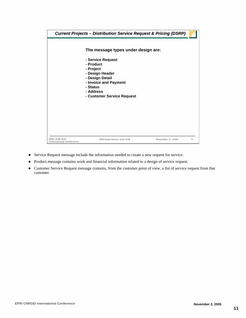
11EPRI CIM/GID International Conference November 2, 2005
11SCE Experiences with CIM November 2, 2005EPRI CIM/GID International Conference
The message types under design are:
- Service Request- Product- Project- Design Header - Design Detail- Invoice and Payment- Status- Address- Customer Service Request
Current Projects Current Projects –– Distribution Service Request & Pricing (DSRP)Distribution Service Request & Pricing (DSRP)
Service Request message include the information needed to create a new request for service.
Product message contains work and financial information related to a design of service request.
Customer Service Request message contains, from the customer point of view, a list of service request from that customer.

12EPRI CIM/GID International Conference November 2, 2005
12SCE Experiences with CIM November 2, 2005EPRI CIM/GID International Conference
ServiceRequest(f rom SCE Extensi...)
<<SCE>>
DocErpPersonRole(f rom TopLev el)
ActivityRecord(f rom Activ ity Records)
MT_ServiceRequest<<Root>>
Customer(f rom Consum...)
Request(f rom WorkInitiation)
11
0..n
0..n
0..n
0..n
Organisation(f rom TopLev el)
Document(f rom DocumentInheritancePackage)
0..n0..n
0..n0..n
ErpPerson(f rom ERP_Support)
0..n 0..n0..n 0..n
0..n
0..n
0..n
0..n
Current Projects Current Projects –– Distribution Service Request & Pricing (DSRP)Distribution Service Request & Pricing (DSRP)
Service Request UML Diagram.
MT_ServiceRequest MT is message type.
SCE extension is needed for SCE specific service request attributes.
Te DocErpPersonRole class is used to specify what role the ErpPerson performs in the given situation.

13EPRI CIM/GID International Conference November 2, 2005
13SCE Experiences with CIM November 2, 2005EPRI CIM/GID International Conference
Current Projects Current Projects –– Distribution Service Request & Pricing (DSRP)Distribution Service Request & Pricing (DSRP)
The XML Schema logical diagram
The diagram produced by the MDI Workbench depicts logical structure of the message type.
It looks quite different from the UML model, which has inheritance and implied relationship.
The semantic shown on this diagram comes from the CIM UML model so they are consistent.
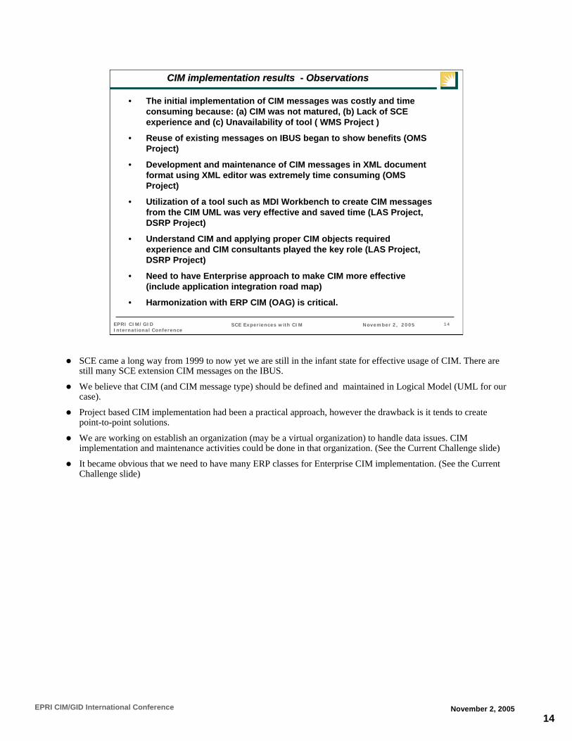
14EPRI CIM/GID International Conference November 2, 2005
14SCE Experiences with CIM November 2, 2005EPRI CIM/GID International Conference
CIM implementation results CIM implementation results -- ObservationsObservations
• The initial implementation of CIM messages was costly and time consuming because: (a) CIM was not matured, (b) Lack of SCE experience and (c) Unavailability of tool ( WMS Project )
• Reuse of existing messages on IBUS began to show benefits (OMS Project)
• Development and maintenance of CIM messages in XML document format using XML editor was extremely time consuming (OMS Project)
• Utilization of a tool such as MDI Workbench to create CIM messages from the CIM UML was very effective and saved time (LAS Project,DSRP Project)
• Understand CIM and applying proper CIM objects required experience and CIM consultants played the key role (LAS Project,DSRP Project)
• Need to have Enterprise approach to make CIM more effective (include application integration road map)
• Harmonization with ERP CIM (OAG) is critical.
SCE came a long way from 1999 to now yet we are still in the infant state for effective usage of CIM. There are still many SCE extension CIM messages on the IBUS.
We believe that CIM (and CIM message type) should be defined and maintained in Logical Model (UML for our case).
Project based CIM implementation had been a practical approach, however the drawback is it tends to create point-to-point solutions.
We are working on establish an organization (may be a virtual organization) to handle data issues. CIM implementation and maintenance activities could be done in that organization. (See the Current Challenge slide)
It became obvious that we need to have many ERP classes for Enterprise CIM implementation. (See the Current Challenge slide)

15EPRI CIM/GID International Conference November 2, 2005
15SCE Experiences with CIM November 2, 2005EPRI CIM/GID International Conference
LDMPDM
Current Challenge Current Challenge -- Going to Enterprise CIM EnvironmentGoing to Enterprise CIM Environment
Application A
Application B
ECDM(ER-Diagram)
CIM Message Schema(XSD)
DB ADB B
CommonService
LDMPDM
BusinessProcess Model
CIM ConceptualModel(UML)
BusinessWare
Project/BURepository
IndustryDrives,
WG 13, 14, 16,Etc.
SCE Project
ECDMRepository
ReconcileData Models
Implement the Common
Service (CIM) just once and
reuse
Con
nect
or
Con
nect
orEach new
participating app. has to only develop
its own connectors
Keys to Success• Semantic understanding• Judicious customization
Keys to Success• SCE systems knowledge• XML/integration expertise
Keys to Success• Process understanding• Business/IT Partnership
Keys to Success• Businessware knowledge• SOA knowledge/skill
IBUS
This diagram promote understanding of the CIM implementation environment at SCE. (Promote Enterprise view)
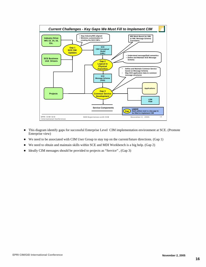
16EPRI CIM/GID International Conference November 2, 2005
16SCE Experiences with CIM November 2, 2005EPRI CIM/GID International Conference
Current Challenges - Key Gaps We Must Fill to Implement CIM
SCEMessage Schema
(XSD)
SCECIM Conceptual
Model(UML)
Gap 1SCE CIM Updates
Gap 2Logical toPhysical
Transition
Applications
LDMPDM
Gap 3Common Service
Development
Service Components
Industry DriveWG 13, 14, 16,
Etc.
SCE Business Unit Drivers
Projects
• Stay Industry/WG aligned• Minimize customization in
creating the SCE CIM’s
• Understand message/field semantics• Define and Maintain SCE Message
Schema
• Define and Maintain Common Service based on Message Schema
• Map SCE application data to common message structures
GapLegendEach yellow oval is a key gap to be filled to implement CIM
MDI Work Bench for UML to XML Message Schema Translation
This diagram identify gaps for successful Enterprise Level CIM implementation environment at SCE. (Promote Enterprise view)
We need to be associated with CIM User Group to stay top on the current/future directions. (Gap 1)
We need to obtain and maintain skills within SCE and MDI Workbench is a big help. (Gap 2)
Ideally CIM messages should be provided to projects as “Service” , (Gap 3)

17EPRI CIM/GID International Conference November 2, 2005
17SCE Experiences with CIM November 2, 2005EPRI CIM/GID International Conference
Challenges – Model-Driven Integration for ERP
APP APP
APP APP
APP
APP
ERPIBUS (XML Message) Interface
IEC TC 57WGs
OpenApplication
Group
IEC TC 57 Logical Model(UML)
OAGLogicalModel(UML)
SCE ExtensionLogical Model(UML)
SCERequirements
Logical Model (UML)
Physical Components
(XML Message)
MDI Workbench
UML to XML Message Schema Translation
ERP to legacy applications integration based on CIM based messages.
Currently OAGIS messages are available in XML schema
Effort is underway to develop UML
As OAGIS develop UML we can integrate ERP to legacy applications based on the logical model and use MDI Workbench for UML to XML translation
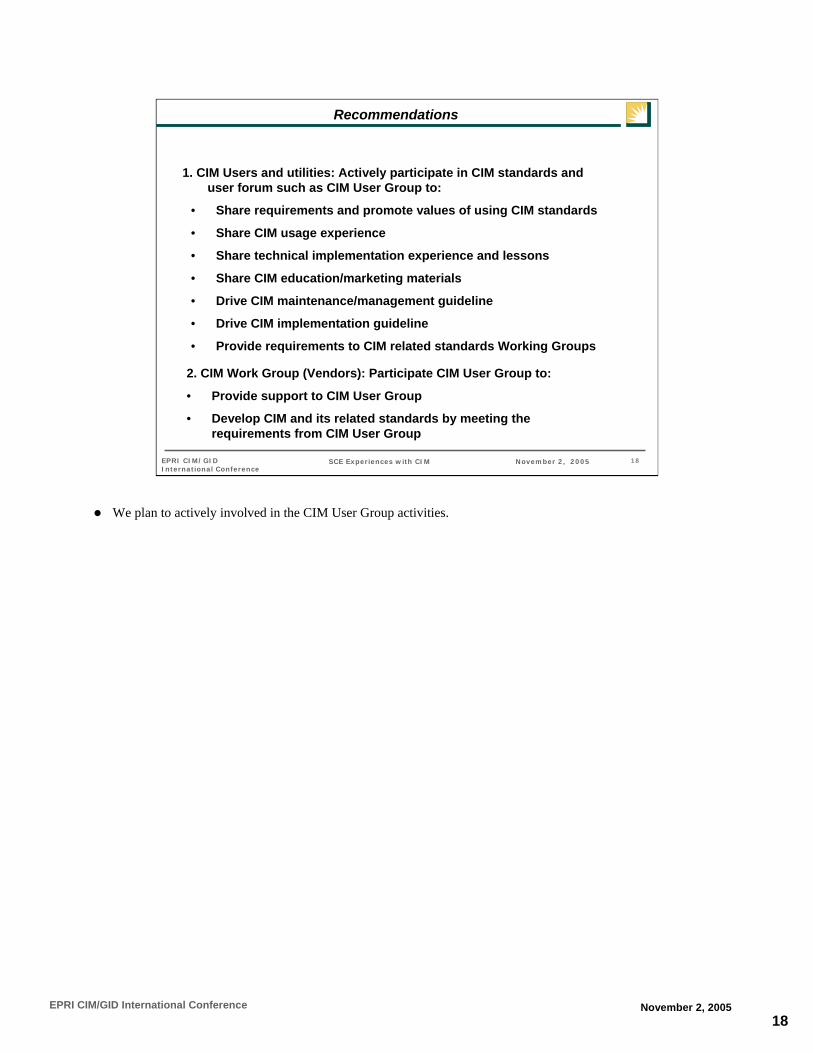
18EPRI CIM/GID International Conference November 2, 2005
18SCE Experiences with CIM November 2, 2005EPRI CIM/GID International Conference
Recommendations
• Share requirements and promote values of using CIM standards
• Share CIM usage experience
• Share technical implementation experience and lessons
• Share CIM education/marketing materials
• Drive CIM maintenance/management guideline
• Drive CIM implementation guideline
• Provide requirements to CIM related standards Working Groups
1. CIM Users and utilities: Actively participate in CIM standards and user forum such as CIM User Group to:
2. CIM Work Group (Vendors): Participate CIM User Group to:
• Provide support to CIM User Group
• Develop CIM and its related standards by meeting the requirements from CIM User Group
We plan to actively involved in the CIM User Group activities.

19EPRI CIM/GID International Conference November 2, 2005
19SCE Experiences with CIM November 2, 2005EPRI CIM/GID International Conference
SCE ContactsSCE Contacts
Southern California Edison CIM Contacts
Shigetaka (Taka) Kikkawa [email protected] CIM UG, WG 14, Enterprise Architecture
Hugo Reyes [email protected] CIM UG, WG 13
Robert Yinger [email protected] UCA, CIM Coordination in SCE
Please feel free to contact us for any questions or comments.
Hugo Reyes and/or Taka Kikkawa for the CIM technical issues.
Robert Yinger represents SCE for UCA (as an UCA Executive Committee member)

20EPRI CIM/GID International Conference November 2, 2005
20SCE Experiences with CIM November 2, 2005EPRI CIM/GID International Conference
Support Slides

21EPRI CIM/GID International Conference November 2, 2005
21SCE Experiences with CIM November 2, 2005EPRI CIM/GID International Conference
Current Initiative Current Initiative –– Going to CIM EnvironmentGoing to CIM Environment
DefineIntegrationScenario
Identify MessageTypes
& Contents
Define/ReviseCIM Classes
For Messages
ProjectRequirements
Implementation
SCE CIM in UML
- Business Process - Use Cases
MDI Workbench
Generate CIMMessage Type
In XMLSchema
SCE CIM MessageTypes in XSD
Message TypesContents
ECDMInformation
UsageModel
SCE CIM Model Manager maintains SCE CIM in Rational Rose and provide support to project for creating CIM Message Types
CIM Message Type DevelopmentCIM Message Type Development

22EPRI CIM/GID International Conference November 2, 2005
22SCE Experiences with CIM November 2, 2005EPRI CIM/GID International Conference
CIM Implementation ProcessCIM Implementation Process–– Going to CIM EnvironmentGoing to CIM Environment
SCE CIM MessageTypes in XSD
Work with EAI to determine
ResourceRequirements
LDMPDM
EAI System Engineer
- Business Process - Use Cases
DefineIntegrationScenario
ProjectRequirements
DevelopData
TransformerComponent
SupportDevelop
EAI Resource Requirements
Provide EAI Resources
ConductTest
Application Interface DevelopmentApplication Interface Development
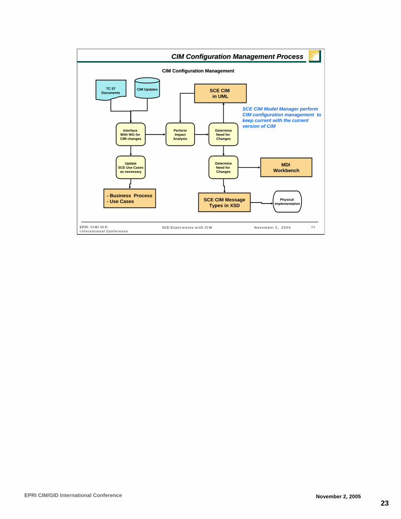
23EPRI CIM/GID International Conference November 2, 2005
23SCE Experiences with CIM November 2, 2005EPRI CIM/GID International Conference
CIM Configuration Management ProcessCIM Configuration Management Process
SCE CIM in UML
- Business Process - Use Cases
MDI Workbench
SCE CIM MessageTypes in XSD
TC 57Documents
CIM Updates
Interface With WG for CIM changes
UpdateSCE Use Cases
as necessary
PerformImpact
Analysis
DetermineNeed for Changes
DetermineNeed for Changes
Physical Implementation
SCE CIM Model Manager perform CIM configuration management to keep current with the current version of CIM
CIM Configuration ManagementCIM Configuration Management

1
1
The CIM within ExelonDean M. HengstLead AnalystExelon Business Services, Information Technology
EPRI CIM/GID International ConferenceNovember 1-2, 2005
2
The CIM within ExelonCompany OverviewProject BackgroundProject ImplementationBuilding an Enterprise Standard for ExelonLessons LearnedQuestions

2
3
Who we are….Parent Company Exelon
A Generation CompanyAn Energy Delivery Company serving Chicago, Northern Illinois and the Philadelphia Area serving 5.1 Million CustomersA Power Marketing CompanyServes 460,000 Gas Customers in the Philadelphia areaCorporate Headquarters – Chicago, Illinois
4
The CIM within ExelonCompany OverviewProject BackgroundProject ImplementationBuilding an Enterprise Standard for ExelonLessons LearnedQuestions

3
5
CIM Related ProjectsCurrent Projects
Powertools Consists of three major applications in the West (ComEd)
Outage Management System (OMS)SCADA SystemControl Area Management System (CAMS)
In-Flight projectsCommon Customer System
Leverage West OMS interfaces
Future Projects under ConsiderationEnterprise Mobile Workforce ManagementSCADA in the East (PECO)
6
Powertool’s Decision to use the CIM
The project needed a message model quickly and the CIM had most components already modeledThe CIM is easily extendable if not all of the components were modeled and future expansion if necessaryThe CIM is a utility standard and endorsed by the Standards BodiesThe CIM model was being utilized in the transmission areaStriving to become a top quartile Energy Delivery Company by creating reusable practices
Within the Powertools Project, there are many systems that need to be integrated together. Thus, a model was needed to ensure that the interfaces would have a common language.

4
7
CIM Compliant Areaswithin PowerTools
OMSStatus On DemandTrouble TicketOutage StatusOutage HistoryCallbacksElectrical Configuration Data
SCADAStorage of Data
TransmissionDistributionTelemetry (CIM Extended for this model)
8
A view of the OMS Interfaces
Outage Management System(West)
Geographical Information System(West)
Common CustomerInformation System
IVR
VRU
SRPIRSeOutage
21
1 – Callbacks2 – Status on Demand3 – Outage Status Query4 – Outage Notes History5 – Trouble Ticket6 – Outage History7 – Electrical Data
7
6
1
Outage Management System(East)
43 5
The same language is important once multiple systems are involved in data transfer.

5
9
The CIM within ExelonCompany OverviewProject BackgroundProject ImplementationBuilding an Enterprise Standard for ExelonLessons LearnedQuestions
10
MessagesKeep the message simpleEnsure all attributes from the originating system is modeledPick an acceptable message format (for example: XML)Document attribute mappings in an easy to understand formatHave system matter experts on hand to work with the message mapping teamKeep future and current systems in mind while doing the mappingsKnowledge of the technology transport can be beneficial to the message mapping team

6
11
Applying the CIM to messaging
Message: Outage Status Inquiry Return Originating Application: Outage Management SystemDestination Application: Customer System
Current number of customers affected
OutageReport.totalCustomersIntegercurCustAff
Cause CodesOutageRecord.outageTypeStringcauseCodes
Outage CommentActivityRecord.remarksStringoutageCmnt
Estimated Restore TimeOutageStep.estRestoreDateTimeDateTimeestRepairTime
Outage Begin TimeOutageRecord.startDateTimeDateTimetimeStamp
Outage StatusOutageRecord.docStatusStringStatus
Master Ticket NumberOutageRecord.nameStringoutageNo
CommentCIM EquivalentTypeOMS Attribute
Map application attributes to CIM equivalent. Determine transformation requirements.
Application AAttribute CIM Equivalent Application B
Attribute
Perform message mapping from Application A to CIM to Application B.
12
Creating CIM-based messages
<?xml version="1.0" encoding="UTF-8"?><OutageStatusReturnO xmlns:xsi="http://www.w3.org/2001/XMLSchema-instance" xsi:noNamespaceSchemaLocation="OutageStatusReturnO.xsd">
<OutageRecord><OutageRecord.name>String</OutageRecord.name><OutageRecord.docStatus>String</OutageRecord.docStatus><OutageRecord.startDateTime>20011217 093047</OutageRecord.startDateTime><OutageRecord.outageType>String</OutageRecord.outageType><OutageCode>
<OutageCode.name>String</OutageCode.name><OutageCode.name>String</OutageCode.name><OutageCode.name>String</OutageCode.name>
</OutageCode><OutageReport>
<OutageReport.totalCustomers>0</OutageReport.totalCustomers></OutageReport><OutageStep>
<OutageStep.estRestoreDateTime>2001-12-17T09:30:47</OutageStep.estRestoreDateTime>
</OutageStep><TroubleTicket>
<ActivityRecord.remarks>String</ActivityRecord.remarks></TroubleTicket>
</OutageRecord>
Sample CIM Document – Outage Status Return

7
13
Creating CIM-based messagesCIM Schema Definition – Outage Status Return
Identify CIM Schema needed to
build message.Generate XML from
the Model.
OutageStatusReturnO
type… OutageRecord
type…
OutageReport
type… OutageCache.name
type xs:string
OutageStep
type… OutageStep.estRestoreDateTime
type xs:datetime
OutageReport
type… OutageReport.totalCustomers
type xs:integer
OutageCode
type… OutageCode.Name
type xs:string
OutageRecord.name
type xs:string
OutageRecord.docStatus
type xs:string
OutageRecord.startDateTime
type xs:dateTime
OutageRecord.outageType
type xs:string
14
Technology TransportPick a technology transport that is suitable for your needs. In our case:
Websphere MQWebsphere MQ IntegratorFTP
Choose how to utilize your technology transport. In our case:
Clustered Queue ManagersPoint to Point Connections

8
15
AdaptersWrote two adapters
C++Java
Shared with our vendor for consistencyShared with other groups in Exelon IT for reusability and defining a standardBoth adapters have slightly different functionality based upon available libraries for each programming languageCan be used to transform messages
16
Application
Generic Adapter
Wrapper
XSLTEngine
MQ API(client with
storage)
Msgflows
MQ Adapter
General
Architecture(C/C++ and Java)
Application libraries
(.jar, .dll, .so, .sl)
MQ Integrator
MQ ManagersMQ
Developing a Middleware Adapter
A Generic Adapter was designed for use with ComEd and Vendor Applications.
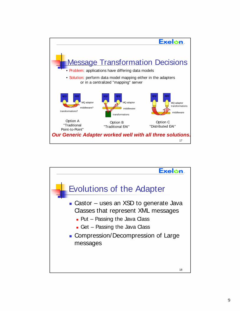
9
17
• Problem: applications have differing data models
• Solution: perform data model mapping either in the adapters or in a centralized "mapping" server
middleware
app app
transformations
middleware
Option C"Distributed EAI"
app app
transformations
Option B"Traditional EAI"
MQ adapter
middleware?
app app
transformations?
Option A"Traditional
Point-to-Point"
MQ adapter
Message Transformation Decisions
Our Generic Adapter worked well with all three solutions.
MQ adapter
18
Evolutions of the AdapterCastor – uses an XSD to generate Java Classes that represent XML messages
Put – Passing the Java ClassGet – Passing the Java Class
Compression/Decompression of Large messages
10
19
The CIM within ExelonCompany OverviewProject BackgroundProject ImplementationBuilding an Enterprise Standard for ExelonLessons LearnedQuestions
20
Building an Enterprise Standard for Exelon
Currently the CIM Model is not an Enterprise Standard within ExelonEnterprise Architecture taking ownership instead of projectsEnterprise Architecture would be responsible for educating the company on the CIMFuture projects should leverage thePowerTools integration framework

11
21
The CIM within ExelonCompany OverviewProject BackgroundProject ImplementationBuilding an Enterprise Standard for ExelonLessons LearnedQuestions
22
Project Lessons LearnedBring in experienced consultants throughout the design, development and
testing cycles
Spend more time upfront planning and “proto-typing”
Recognize that a broad base of skills, technologies and tools are involved
Don’t under estimate the configuration and testing involved
Bring in experts in the different technologies in order to make the integration smoother
Don’t expect your application vendors to be experts in EAI
Leverage existing corporate standards and infrastructure where possible
Communicate strategy and direction
12
23
Corporate Lessons LearnedThere needs to be Executive Sponsorship
Assign an Owner (Enterprise Architecture)
Build a detailed knowledge owner to prep new projects on the CIM and our EAI architecture
Communicate, Educate, Re-Enforce and Celebrate Successes
Participate in Industry events to stay current and help drive the direction
Don’t expect immediate payback – critical mass not achieved immediately
Understand there can be more points of failure in the overall interface design
Ensure all owners of the infrastructure and software are willing to co-operate during interface problems
24
The CIM within ExelonCompany OverviewProject BackgroundProject ImplementationBuilding an Enterprise Standard for ExelonLessons LearnedQuestions

13
25
Questions?
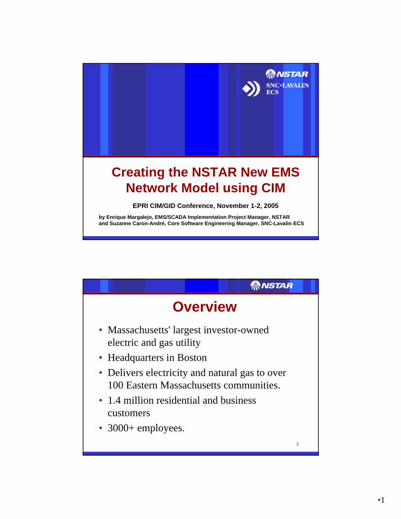
•1
Creating the NSTAR New EMS Network Model using CIM
EPRI CIM/GID Conference, November 1-2, 2005by Enrique Margalejo, EMS/SCADA Implementation Project Manager, NSTARand Suzanne Caron-André, Core Software Engineering Manager, SNC-Lavalin ECS
2
Overview• Massachusetts' largest investor-owned
electric and gas utility• Headquarters in Boston • Delivers electricity and natural gas to over
100 Eastern Massachusetts communities.• 1.4 million residential and business
customers• 3000+ employees.
•2
3
Service Territory
4
Transmission Context

•3
5
New EMS System• NSTAR commissioned a GEN-4 system
from SNC-Lavalin ECS as its new EMS-SCADA system, in replacement of the current GEN-3 SCADA system.
• The EMS will support NSTAR Electric Operations and will allow NSTAR to function as a satellite control center for ISO-NE, for NSTAR’s service territory.
6
EMS Network Model• NSTAR’s EMS Network Model comprises:
– A Full ISO-NE transmission network (External Model)– The NSTAR’s internal bulk transmission network
(Internal Network)• NSTAR licensed ODMS from Power Technologies
International (PTI) to create, expand and merge the Internal and External Models into a CIM-compliant database
• Iterative CIM-based file transfers between ODMS and the EMS were used to arrive at a working EMS Network Model and Model Management Process.

•4
7
C loud
IS O -N E T ransm iss ion N e tw ork
E XT E R N A LXM IS S IO NN E T W O R KD E T A ILE D
M O D E L
N S T A R D is tribu tionA u tom ation :- F eeder C apac ito r C on tro l- V o ltage R egu la tion
N S T A R E M SV V S func tion
N S T A R IN T E R N A LXM IS S IO N N E T W O R K
D E T A ILE D M O D E L
F igu re 1
N S T A RD IS T R IB U T IO N
N E T W O R K
N S T A RT ransm iss ion
&D is tr ibu tion
N e tw ork
NSTAR’s Model Build
8
Model Development & Management Strategy
• Use CIM/XML as the data import/export format for model data transfers
• Import ISO-NE’s Network model as the External Network• Gradually develop the details of the NSTAR Internal
Model• Follow up on the footsteps of ISO-NE network model
releases:– Match ISO-NE periodic releases (now every 3 months)– Implement a model building process including periodic
model merging and CIM incremental updates
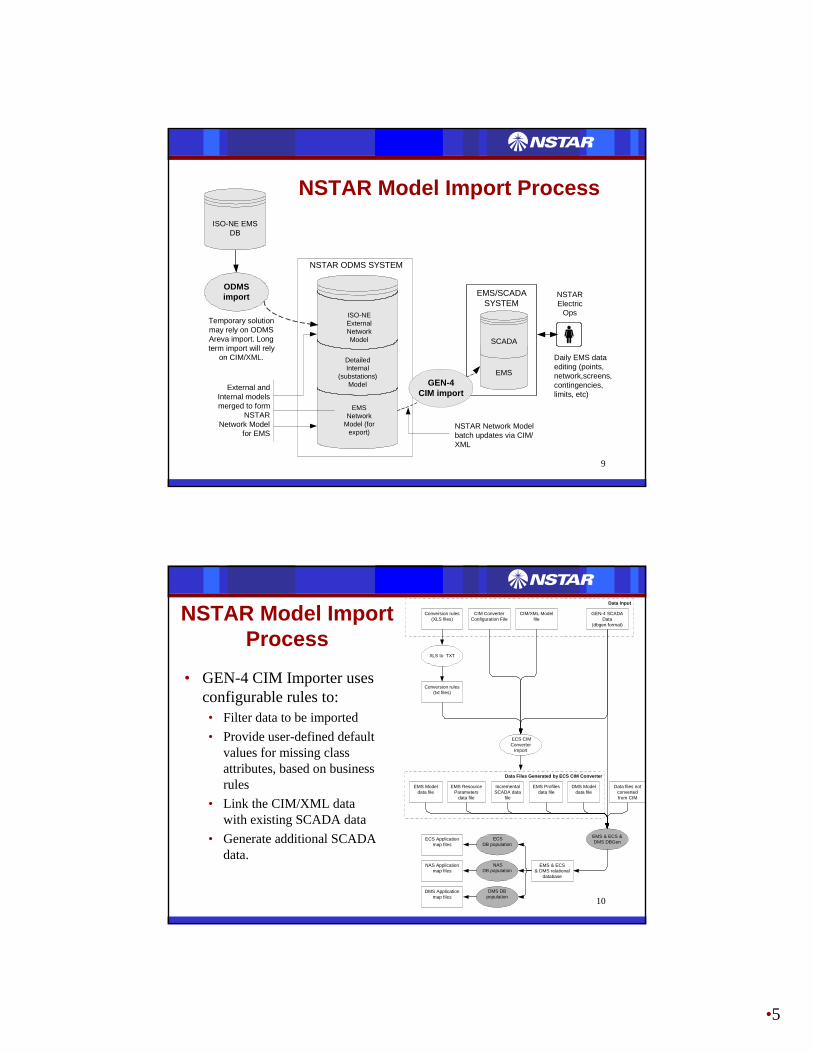
•5
9
NSTAR Model Import Process
NSTAR Network Modelbatch updates via CIM/XML
Temporary solutionmay rely on ODMSAreva import. Longterm import will rely
on CIM/XML.
NSTAR ODMS SYSTEM
ODMSimport
ISO-NEExternalNetworkModel
EMSNetwork
Model (forexport)
DetailedInternal
(substations)ModelExternal and
Internal modelsmerged to form
NSTARNetwork Model
for EMS
EMS/SCADASYSTEM
EMS
SCADA
NSTARElectric
Ops
Daily EMS dataediting (points,network,screens,contingencies,limits, etc)
GEN-4CIM import
ISO-NE EMSDB
10
Data Files Generated by ECS CIM Converter
Data Input
Conversion rules(XLS files)
CIM/XML Modelfile
XLS to TXT
Conversion rules(txt files)
ECS CIMConverter
Import
GEN-4 SCADAData
(dbgen format)
Data files notconvertedfrom CIM
EMS Modeldata file
EMS & ECS &DMS DBGen
EMS & ECS& DMS relational
database
NAS Applicationmap files
NASDB population
CIM ConverterConfiguration File
IncrementalSCADA data
file
EMS ResourceParameters
data file
EMS Profilesdata file
DMS Applicationmap files
DMS DBpopulation
ECS Applicationmap files
ECSDB population
DMS Modeldata file
• GEN-4 CIM Importer uses configurable rules to:• Filter data to be imported• Provide user-defined default
values for missing class attributes, based on business rules
• Link the CIM/XML data with existing SCADA data
• Generate additional SCADA data.
NSTAR Model Import Process

•6
11
Lessons Learned• Adopt ISO naming conventions• Rely on ISN ICCP file definitions for ICCP data• Use iterative approach to CIM data transfer• Be careful with:
– Placement of measurements– Transformers and shifter taps– Limits– Duplicate object IDs
12
Lessons Learned• Team up System Planning and Operations • Develop SCADA-to-EMS data checking tools• Use load flows at both CIM data ends for data
validation • Harmonize / adapt CIM model implementations
and CIM import/export tools• Use CPSM NERC Profile as the main source to
clarify CIM implementation issues
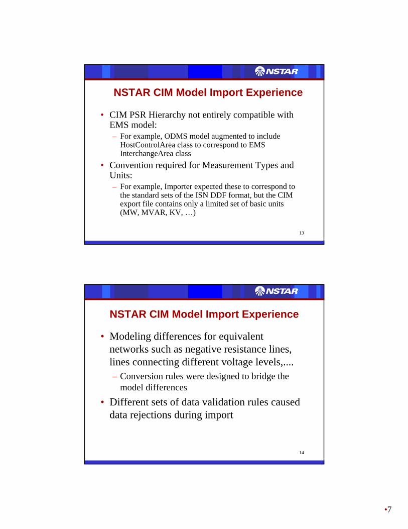
•7
13
NSTAR CIM Model Import Experience
• CIM PSR Hierarchy not entirely compatible with EMS model:– For example, ODMS model augmented to include
HostControlArea class to correspond to EMS InterchangeArea class
• Convention required for Measurement Types and Units:– For example, Importer expected these to correspond to
the standard sets of the ISN DDF format, but the CIM export file contains only a limited set of basic units(MW, MVAR, KV, …)
14
NSTAR CIM Model Import Experience
• Modeling differences for equivalent networks such as negative resistance lines, lines connecting different voltage levels,....– Conversion rules were designed to bridge the
model differences• Different sets of data validation rules caused
data rejections during import

•8
15
NSTAR CIM Model Import Experience
• Unique object Id and RDF ID were not persistent across re-imports and cannot be used for future incremental updates– A specification was designed to generate unique,
persistent object names, which will be used as persistent key for incremental updates
• Modeling of Limits: use only the CIM LimitSet class rather than attributes of specialized PSR classes
16
NSTAR CIM Model Import Experience
• Important enhancement to consider: systematical use of CIMValidator to detect invalid syntax. New validation tool required to detect:– references to non-existent objects– invalid or missing CPSM class attributes– validation rules violations.
• These tools should be designed/enhanced for performance for large files (last NSTAR export approx. 200 Mb)

•9
17
NSTAR CIM Model Import Status• June 05 ISO-NE External network model
expanded with 70 NSTAR Stations imported and converged in EMS (1000 Station model)
• Complete CIM/XML import process (including validation, data corrections and running the EMS State Estimator) takes approximately 1 week. This time should be reduced once tighter process controls are in place.
18
NSTAR CIM Model Future Developments
• Next challenge will be integration of incremental update tools in the Network Model Management process– will require harmonization of CIM Incremental
Updates between the different parties with the primary objective of minimizing disruption to the on-line EMS system

•10
19
Creating the NSTAR New EMS Network Model using CIM
Questions?

1
AuthorAffiliation
CIMCIM--GID GID Interoperability Test 7 ReportInteroperability Test 7 Report
Testing A Standardized Integration Testing A Standardized Integration StrategyStrategy
Margaret GoodrichMargaret GoodrichProject Consultants, LLCProject Consultants, LLC
© 2005 Project Consultants, LLC All rights reserved. Page 2
TopicsTopics
•• What is the Interoperability (IOP) TestWhat is the Interoperability (IOP) Test•• Purpose of the IOP TestPurpose of the IOP Test•• IOP History IOP History •• IOP 7 ParticipantsIOP 7 Participants•• IOP 7 ContentsIOP 7 Contents•• IOP7 HighlightsIOP7 Highlights•• General Issues & SolutionsGeneral Issues & Solutions•• Future IOP ContentsFuture IOP Contents

2
© 2005 Project Consultants, LLC All rights reserved. Page 3
What is the Interoperability TestWhat is the Interoperability Test
•• Test the Interoperability of CIM XML extracts Test the Interoperability of CIM XML extracts produced by various vendorsproduced by various vendors
•• Ensure the NERC CPSM Profile for Data Ensure the NERC CPSM Profile for Data Exchange can be implemented as specifiedExchange can be implemented as specified
•• Test the Interoperability of the Generic Interface Test the Interoperability of the Generic Interface Definition (GID) StandardsDefinition (GID) Standards
•• Test the Interoperability of WG14 CIM StandardsTest the Interoperability of WG14 CIM Standards•• Test the Interoperability of WG14 Messaging Test the Interoperability of WG14 Messaging
StandardsStandards
© 2005 Project Consultants, LLC All rights reserved. Page 4
Purpose of the IOP TestPurpose of the IOP Test
•• To verify that the applications developed using To verify that the applications developed using the IEC standards can interoperatethe IEC standards can interoperate
•• To provide an opportunity for the industry to To provide an opportunity for the industry to identify any deficiencies in the standard or the identify any deficiencies in the standard or the use cases under testuse cases under test

3
© 2005 Project Consultants, LLC All rights reserved. Page 5
IOP Test HistoryIOP Test History•• The concept for an Interoperability Test was initially The concept for an Interoperability Test was initially
conceived at a CCAPI meeting by the XML conceived at a CCAPI meeting by the XML Breakout Team to test the CIM XML exchange Breakout Team to test the CIM XML exchange standardstandard
•• The vendors approached EPRI about sponsorship and The vendors approached EPRI about sponsorship and EPRI agreed to act as sponsor and provide EPRI agreed to act as sponsor and provide independent verificationindependent verification
•• Vendors began work on Test ImplementationVendors began work on Test Implementation•• IOP Tests have been onIOP Tests have been on--going for the past 5 yearsgoing for the past 5 years•• IOP Tests now include all WG13 and WG14 IOP Tests now include all WG13 and WG14
standards as they become availablestandards as they become available
© 2005 Project Consultants, LLC All rights reserved. Page 6
IOP 7 ParticipantsIOP 7 Participants
•• EPRIEPRI•• ABBABB•• ArevaAreva•• EDFEDF•• Siemens Siemens PTIPTI•• SiemensSiemens•• SISCOSISCO
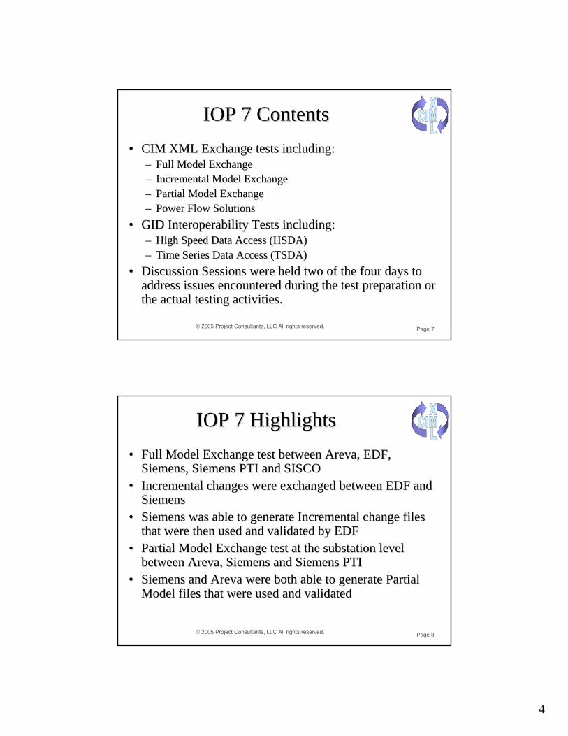
4
© 2005 Project Consultants, LLC All rights reserved. Page 7
IOP 7 ContentsIOP 7 Contents•• CIM XML Exchange tests including:CIM XML Exchange tests including:
–– Full Model ExchangeFull Model Exchange–– Incremental Model ExchangeIncremental Model Exchange–– Partial Model ExchangePartial Model Exchange–– Power Flow SolutionsPower Flow Solutions
•• GID Interoperability Tests including:GID Interoperability Tests including:–– High Speed Data Access (HSDA)High Speed Data Access (HSDA)–– Time Series Data Access (TSDA)Time Series Data Access (TSDA)
•• Discussion Sessions were held two of the four days to Discussion Sessions were held two of the four days to address issues encountered during the test preparation or address issues encountered during the test preparation or the actual testing activities.the actual testing activities.
© 2005 Project Consultants, LLC All rights reserved. Page 8
IOP 7 HighlightsIOP 7 Highlights•• Full Model Exchange test between Full Model Exchange test between ArevaAreva, EDF, , EDF,
SiemensSiemens, , Siemens Siemens PTI and SISCOPTI and SISCO•• Incremental changes were exchanged between EDF and Incremental changes were exchanged between EDF and
SiemensSiemens•• Siemens Siemens was able to generate Incremental change files was able to generate Incremental change files
that were then used and validated by EDFthat were then used and validated by EDF•• Partial Model Exchange test at the substation level Partial Model Exchange test at the substation level
between between ArevaAreva, , SiemensSiemens andand SiemensSiemens PTIPTI•• Siemens Siemens and and Areva Areva were both able to generate Partial were both able to generate Partial
Model files that were used and validatedModel files that were used and validated
5
© 2005 Project Consultants, LLC All rights reserved. Page 9
IOP 7 HighlightsIOP 7 Highlights•• EDF successfully completed the Power Flow Solution EDF successfully completed the Power Flow Solution
teststests•• ABB, EDF, ABB, EDF, SiemensSiemens, , SiemensSiemens PTI and SISCO were all PTI and SISCO were all
able to demonstrate High Speed Data Access (HSDA) able to demonstrate High Speed Data Access (HSDA) exchangesexchanges
•• The HSDA test utilized four different types of The HSDA test utilized four different types of middlewaremiddleware
•• Siemens Siemens PTI and SISCO exchanged historical data via a PTI and SISCO exchanged historical data via a Time Series Data Access (TSDA) client/server pair using Time Series Data Access (TSDA) client/server pair using message bus middlewaremessage bus middleware
© 2005 Project Consultants, LLC All rights reserved. Page 10
IOP 7 HighlightsIOP 7 Highlights•• Many participants used multiple models to complete the Many participants used multiple models to complete the
exchange tests including a 100 bus model from exchange tests including a 100 bus model from SiemensSiemens, , a 60 bus model from a 60 bus model from ArevaAreva, a 40 bus model from ABB , a 40 bus model from ABB and two models from EDF (a 27 node from EDF and a and two models from EDF (a 27 node from EDF and a 14 node using the UCTE format)14 node using the UCTE format)
•• The discussion sessions discovered 100 issues and The discussion sessions discovered 100 issues and provided over 60 proposed solutions.provided over 60 proposed solutions.
•• All issues and proposed solutions will be forwarded to All issues and proposed solutions will be forwarded to the appropriate Working Group for consideration and the appropriate Working Group for consideration and final resolution. final resolution.

6
© 2005 Project Consultants, LLC All rights reserved. Page 11
General Issues and SolutionsGeneral Issues and Solutions
•• On Monday prior to the IOP 7 test, CAISO hosted a On Monday prior to the IOP 7 test, CAISO hosted a workshop for the IOP participants and the Utilities and workshop for the IOP participants and the Utilities and ISO that had implemented project using the CIM XML ISO that had implemented project using the CIM XML Exchange standardsExchange standards
•• Major Workshop IssuesMajor Workshop Issues–– Lack of CIMXML file compliance to CPSMLack of CIMXML file compliance to CPSM–– Naming IssuesNaming Issues–– Modeling IssuesModeling Issues–– Lack of rigid rules and practices in the CIM Standard or Lack of rigid rules and practices in the CIM Standard or
ProfilesProfiles–– More/Better CIM toolsMore/Better CIM tools
© 2005 Project Consultants, LLC All rights reserved. Page 12
General Issues & SolutionsGeneral Issues & Solutions•• Continue Rigorous review of CIM XML models to Continue Rigorous review of CIM XML models to
ensure compliance to CPSM and other profilesensure compliance to CPSM and other profiles•• Increase the working sessions to address issues, develop Increase the working sessions to address issues, develop
resolutions and include these issues in the tests to verify resolutions and include these issues in the tests to verify the resolutionthe resolution
•• Work closely with the IEC Working Groups to obtain Work closely with the IEC Working Groups to obtain the latest changes to the standards and ensure the tests the latest changes to the standards and ensure the tests fully validate thesefully validate these
•• Obtain input from the Utilities to ensure the tests cover Obtain input from the Utilities to ensure the tests cover needed areasneeded areas
•• Generate more elaborate or realGenerate more elaborate or real--world modelsworld models

7
© 2005 Project Consultants, LLC All rights reserved. Page 13
Future IOP ContentsFuture IOP Contents
•• Expand the exchange tests to include distribution Expand the exchange tests to include distribution models and other profilesmodels and other profiles
•• Add tests to verify Messaging Standards defined Add tests to verify Messaging Standards defined in WG14in WG14
•• Add tests for the GES interface standardAdd tests for the GES interface standard•• Expand test for GDA and TSDA to include more Expand test for GDA and TSDA to include more
methods and middleware technologies methods and middleware technologies

1
Technical Committee 57POWER SYSTEMS MANAGEMENT AND ASSOCIATED INFORMATION EXCHANGE
Paul Skare
TC 57
IEC TC57 Standards Harmonization Efforts and Future Vision
Carmel, IN - 2005-11-02
Paul Skare, SiemensConvenor, WG19

2
3
TC 57
What is TC57?
Power systems management and associated information exchangeScope: To prepare international standards for power systems control equipment and systems including EMS (Energy Management Systems), SCADA (Supervisory Control And Data Acquisition), distribution automation, teleprotection, and associated information exchange for real-time and non-real-time information, used in the planning, operation and maintenance of power systems. Power systems management comprises control within control centers, substations and individual pieces of primary equipment including telecontrol and interfaces to equipment, systems and databases, which may be outside the scope of TC 57. Note 1: Standards prepared by other technical committees of the IEC and organizations such as ITU and ISO shall be used where applicable.
WG 19 Status
4
TC 57 WG 19 Status
Market Operation Apps
60870-6-503App Services
SCADA Apps EMS Apps DMS Apps Engineering & Maintenance Apps
ExternalIT Apps
Data Acquisition and Control Front-End / Gateway / Proxy Server / Mapping Services / Role-based Access Control
61850-8-1Mapping to MMS
TC13 WG14
Meter Standards
61334
60870-5101&
104
61970 Component Interface Specification (CIS) 61968 SIDMS for Enterprise Application Integration (EAI)
61970 / 61968 Common Information Model (CIM)
Inter-Application Messaging Middleware, ebXML, and Web Services (specified in XML; mapped to appropriate protocols)
61850 Substation Devices
61850 IED Field Devices
Beyond theSubstation
60870-6TASE.2
Other Control Centers
60870-5RTUs or
SubstationSystems
IEDs, Relays, Meters, Switchgear, CTs, VTs
End
-to-E
nd S
ecur
ity S
tand
ards
and
Rec
omm
enda
tions
(wor
k in
pro
gres
s)
Current TC57 Reference Architecture
External Systems(Symmetric client/server
protocols)
Specific Communication Services Mappings
Specific Object Mappings
ApplicationInterfaces
Equipment AndSystem Interfaces
Telecontrol Communications
Media and Services
Communication Industry Standard Protocol Stacks(ISO/TCP/IP/Ethernet)
XMLMessaging
(work inprogress)
Protocol Profiles
XML MessagingExternal
Systems (e.g., Substations)
WANCommunications
Media and Services
FieldDevices
Utility CustomersEnergyMarket Participants Other Businesses
Application To Application (A2A)and Business To Business
(B2B) Communications
Utility Service Providers
Net
wor
k, S
yste
m, a
nd D
ata
Man
agem
ent
(futu
re)
TC13 WG14
*Notes: 1) Solid colors correlate different parts of protocols within the architecture.2) Non-solid patterns represent areas that are future work, or work in progress, or related work provided by another IEC TC.
61850-7-2 ACSI
61850-7-3, 7-4 Object Models
CustomerMeters
Peer-to-Peer 61850 overSubstation bus and Process bus
60870-6-802Object Models
60870-6-703Protocols
Field Object Models
Market Operation Apps
60870-6-503App Services
SCADA Apps EMS Apps DMS Apps Engineering & Maintenance Apps
ExternalIT Apps
Data Acquisition and Control Front-End / Gateway / Proxy Server / Mapping Services / Role-based Access Control
61850-8-1Mapping to MMS
TC13 WG14
Meter Standards
61334
TC13 WG14
Meter Standards
61334
60870-5101&
104
61970 Component Interface Specification (CIS) 61968 SIDMS for Enterprise Application Integration (EAI)
61970 / 61968 Common Information Model (CIM)
Inter-Application Messaging Middleware, ebXML, and Web Services (specified in XML; mapped to appropriate protocols)
61850 Substation Devices
61850 IED Field Devices
Beyond theSubstation
60870-6TASE.2
Other Control Centers
60870-5RTUs or
SubstationSystems
IEDs, Relays, Meters, Switchgear, CTs, VTs
End
-to-E
nd S
ecur
ity S
tand
ards
and
Rec
omm
enda
tions
(wor
k in
pro
gres
s)
Current TC57 Reference Architecture
External Systems(Symmetric client/server
protocols)
Specific Communication Services Mappings
Specific Object Mappings
ApplicationInterfaces
Equipment AndSystem Interfaces
Telecontrol Communications
Media and Services
Communication Industry Standard Protocol Stacks(ISO/TCP/IP/Ethernet)
XMLMessaging
(work inprogress)
Protocol Profiles
XML MessagingExternal
Systems (e.g., Substations)
WANCommunications
Media and Services
FieldDevices
Utility CustomersEnergyMarket Participants Other Businesses
Application To Application (A2A)and Business To Business
(B2B) Communications
Utility Service Providers
Net
wor
k, S
yste
m, a
nd D
ata
Man
agem
ent
(futu
re)
TC13 WG14
*Notes: 1) Solid colors correlate different parts of protocols within the architecture.2) Non-solid patterns represent areas that are future work, or work in progress, or related work provided by another IEC TC.
61850-7-2 ACSI
61850-7-3, 7-4 Object Models
CustomerMeters
Peer-to-Peer 61850 overSubstation bus and Process bus
60870-6-802Object Models
60870-6-703Protocols
Field Object Models
Users of Power System Functions
Interfaces
Power System Applications
SCADA
Substations and Other Field Devices
Sec
urity
and
Net
wor
k M
anag
emen
t
Current Overview

3
5
TC 57 WG 19 StatusCurrent Detail
Market Operation Apps
60870-6-503App Services
SCADA Apps EMS Apps DMS Apps Engineering & Maintenance Apps
ExternalIT Apps
Data Acquisition and Control Front-End / Gateway / Proxy Server / Mapping Services / Role-based Access Control
61850-8-1Mapping to MMS
TC13 WG14
Meter Standards
61334
60870-5101&
104
61970 Component Interface Specification (CIS) 61968 SIDMS for Enterprise Application Integration (EAI)
61970 / 61968 Common Information Model (CIM)
Inter-Application Messaging Middleware, ebXML, and Web Services (specified in XML; mapped to appropriate protocols)
61850 Substation Devices
61850 IED Field Devices
Beyond theSubstation
60870-6TASE.2
Other Control Centers
60870-5RTUs or
SubstationSystems
IEDs, Relays, Meters, Switchgear, CTs, VTs
End
-to-E
nd S
ecur
ity S
tand
ards
and
Rec
omm
enda
tions
(wor
k in
pro
gres
s)
Current TC57 Reference Architecture
External Systems(Symmetric client/server
protocols)
Specific Communication Services Mappings
Specific Object Mappings
ApplicationInterfaces
Equipment AndSystem Interfaces
Telecontrol Communications
Media and Services
Communication Industry Standard Protocol Stacks(ISO/TCP/IP/Ethernet)
XMLMessaging
(work inprogress)
Protocol Profiles
XML MessagingExternal
Systems (e.g., Substations)
WANCommunications
Media and Services
FieldDevices
Utility CustomersEnergyMarket Participants Other Businesses
Application To Application (A2A)and Business To Business
(B2B) Communications
Utility Service Providers
Net
wor
k, S
yste
m, a
nd D
ata
Man
agem
ent
(futu
re)
TC13 WG14
*Notes: 1) Solid colors correlate different parts of protocols within the architecture.2) Non-solid patterns represent areas that are future work, or work in progress, or related work provided by another IEC TC.
61850-7-2 ACSI
61850-7-3, 7-4 Object Models
CustomerMeters
Peer-to-Peer 61850 overSubstation bus and Process bus
60870-6-802Object Models
60870-6-703Protocols
Field Object Models
Market Operation Apps
60870-6-503App Services
SCADA Apps EMS Apps DMS Apps Engineering & Maintenance Apps
ExternalIT Apps
Data Acquisition and Control Front-End / Gateway / Proxy Server / Mapping Services / Role-based Access Control
61850-8-1Mapping to MMS
TC13 WG14
Meter Standards
61334
TC13 WG14
Meter Standards
61334
60870-5101&
104
61970 Component Interface Specification (CIS) 61968 SIDMS for Enterprise Application Integration (EAI)
61970 / 61968 Common Information Model (CIM)
Inter-Application Messaging Middleware, ebXML, and Web Services (specified in XML; mapped to appropriate protocols)
61850 Substation Devices
61850 IED Field Devices
Beyond theSubstation
60870-6TASE.2
Other Control Centers
60870-5RTUs or
SubstationSystems
IEDs, Relays, Meters, Switchgear, CTs, VTs
End
-to-E
nd S
ecur
ity S
tand
ards
and
Rec
omm
enda
tions
(wor
k in
pro
gres
s)
Current TC57 Reference Architecture
External Systems(Symmetric client/server
protocols)
Specific Communication Services Mappings
Specific Object Mappings
ApplicationInterfaces
Equipment AndSystem Interfaces
Telecontrol Communications
Media and Services
Communication Industry Standard Protocol Stacks(ISO/TCP/IP/Ethernet)
XMLMessaging
(work inprogress)
Protocol Profiles
XML MessagingExternal
Systems (e.g., Substations)
WANCommunications
Media and Services
FieldDevices
Utility CustomersEnergyMarket Participants Other Businesses
Application To Application (A2A)and Business To Business
(B2B) Communications
Utility Service Providers
Net
wor
k, S
yste
m, a
nd D
ata
Man
agem
ent
(futu
re)
TC13 WG14
*Notes: 1) Solid colors correlate different parts of protocols within the architecture.2) Non-solid patterns represent areas that are future work, or work in progress, or related work provided by another IEC TC.
61850-7-2 ACSI
61850-7-3, 7-4 Object Models
CustomerMeters
Peer-to-Peer 61850 overSubstation bus and Process bus
60870-6-802Object Models
60870-6-703Protocols
Field Object Models
6
TC 57 WG 19 StatusFuture Detail
60870-6-703Protocols
Market Operation AppsDMS Apps Engineering &
Maintenance AppsOther
Applications
Data Acquisition and Control Front-End / Gateway / Proxy Server / Mapping Services / Role-based Access Control
61850-8-1MMS
TC13 WG14
Meter Standards
61334
TC13 WG14
Meter Standards
61334
60870-5101&
104
61970 / 61968 Common Information Model (CIM)
Inter-Application Messaging Middleware such as Web Services and ebXML (meta-models specified in XML)
61850 Substation Devices
61850 IED Field Devices
Beyond theSubstation
60870-6TASE.2
60870-5RTUs or
SubstationSystems
IEDs, Relays, Meters, Switchgear, CTs, VTs
End-
to-E
nd S
ecur
ity S
tand
ards
and
Rec
omm
enda
tions
Future TC57 Reference Architecture∗
External Systems(Symmetric client/server
protocols)
Specific Communication Services Mappings
ApplicationInterfaces
Equipment AndSystem Interfaces
ApplicationInterfaces
Equipment AndSystem Interfaces
Telecontrol Communications
Media and Services
Communication Industry Standard Protocol Stacks(ISO/TCP/IP/Ethernet)
Web ServicesBased on XMLMeta-models
Protocol Profiles
Field DevicesAnd Systems
Using Web Services
WANCommunications
Media and Services
FieldDevices
Utility Customers And Energy Service
Providers
EnergyMarket Participants Other Businesses
Application To Application (A2A)and Business To Business
(B2B) Communications
Utility Service Providers
Net
wor
k, S
yste
m, a
nd D
ata
Man
agem
ent
TC13 WG14
*Notes: Red wording indicates new standards work that needs to be done, improved upon, and/or incorporated from other standards
61850-7-3, 7-4 Object Models
CustomerMeters
Peer-to-Peer 61850 overSubstation bus and Process bus
60870-6-802Object Models Field Object Models
EMS AppsSCADA Apps
61968 SIDMS61970 Component Interface Specification (CIS)
Registry of CIM-like and/or Device Object Models
Enterprise Java Beans, Microsoft COM, Web Services, Other?
61850-8-2Web Services
61850-7-2 ACSI
61850-based Object Models
DERs, Meters,Building EMS
Market Operation Data Exchange Objects
Engineering Data Exchange Objects
OtherData Objects
Inter-applicationData Exchanges
Other Control Centers
60870-6-503App Services

4
7
TC 57
What is WG19?
“Interoperability within TC 57 in (the) long term”In October, 2005 a new AHWG was created(07).In January, 2005, AHWG07 was converted to WG19. NP:
As quality codes impact the work of other working groups with regard to work on the CIM (IEC 61970, IEC 61968), and extensions to theCIM that were recommended for IEC 61850, it is clear that quality codes must be in the overall data model as well. Therefore, it is clear that a central repository and process for the overall TC57 CIM work be created. Exclusions: Current versions of standards are not proposed to be changed – rather each standard can then address this issue in its normal maintenance cycle. With regards to the CIM, this new working group would be the coordinator of the electronic model for TC57, ensuring harmonization of the expansion of the CIM. Each working group in TC57 which does CIM related work would have access to a WG specific sectionof the CIM, with this working group ensuring that the overall CIM remains intact, and creates released versions which all working groups can reference in their publications.
WG 19 Status
8
TC 57
Vision Statement
“All new TC57 standards should use/extend the CIM as the common semantics for their configuration/engineering modeling, and 61850 for [SCADA oriented / IED / field] communications. Other existing standards would likely take a mapping approach. Services could also be addressed (61850 services, Web services, security, operations, SOA and GID services could be harmonized). Mainstream Information Technologies shall be evaluated prior to creating new equivalent approaches.”WG19 conceptually is the technical architecture board of TC57.We started discussing a roadmap for the CIM – this will be needed for 61850, showing how these are envisioned to progress across working groups from a lifecycle process perspective. Help focus on a ‘Seamless Architecture’ – not only statically, but over time. The CIM must be a living standard that considers existing implementation impacts.
WG 19 Status

5
9
TC 57
Vision
A common data modeling approach across TC 57Start with UML 2.0 and XMI 2.0 – next step to plan timeframe for this change (allows other tool use) (Short to Mid term) (We wish to be tool independent)Each WG to have a workable file that can combine to a common modelShare files using SharePoint – eRoom being investigated? Internal to TC57. Release only at agreed points with no problems.CMM agreed to coordinate model issues with WG19 Started drafting a vision statement to share with TC57 –to be incorporated in the Reference ArchitectureInvestigating ontologies and lifecycle issues
WG 19 Status
10
TC 57
Common but Decentralized Approach
Architecture
DataModeling
Communication& Quality
Codes
Vocabulary
TC 57:Common
Framework
WG 19 Status

6
11
TC 57
Meeting Summary
Meetings since Summer, 2005Philadelphia, Pennsylvania USA September, 2005
• Meet in conjunction with WG 13, 14, 16 (2.5 day meeting)
Planned MeetingsZurich, Switzerland January, 2006
• In conjunction with WG 13, 14, 16 (1-1.5 day)
Spain or Mexico March, 2006• In conjunction with WG 10, 17, 18 (1-1.5 day)
London, England June, 2006• In conjunction with the SPAG
Unknown Fall 2006• In conjunction with WG13 (2 days)
WG 19 Status
12
TC 57
Work Overview
In progressH. FalkCD 2006-06-01 IS 2007-12-01
Quality Codes57/733/NP
Update in progress to 5g
T. SaxtonAMW2000-12TC57 Reference Architecture
SB1/74/INF
PublishedP. SkareAMW2003-0761850/61970 Harmonization
IEC TR 62357
57/732/INF
In progressE. DobrowolskiCD: 2005-02 CDV: 2006-02 FDIS: 2007-02 IS: 2007-10
AMW1997-09IEVIEC 60050(371)
A1
In progressE. DobrowolskiCD: 2005-02 CDV: 2006-02 FDIS: 2007-02 IS: 2007-10
AMW1984IEVIEC 60050(371)
Current Status
Responsible WG19 Lead
Maintenance Result Date
Review Date
Date Published
DescriptionPublication No.
WG 19 Status
7
13
TC 57
Reference Architecture
Team Leader: Terry SaxtonCurrent version being worked on is r5fDiagram showing the different views on one piece of primary equipment to be in the documentEach WG to have a separate section in the document with a diagram, example, and textAllows each WG to provide input into overall architecture, but maintains an overall view and consistencyIntelligrid vision is being brought inReviewed missing points identified in IntelligridJoint Task force created with WG10 to look at modeling and representation – report available
WG 19 Status
14
TC 57
Vocabulary (IEV)
Team Leader: Ed DobrowolskiThe purpose is to publish in the IEC Global Vocabulary an updated glossary of terms used in TC57.
Working on conflicts – some terms used differently in different working groups
Many obsolete terms.
WG 19 Status

8
15
TC 57
Quality Codes
Team Leader: Herb FalkThe purpose is to map existing uses of quality codes across SCADA systems and subsystems, and set the standard for all new uses of quality codes.
Just getting started – we have some SCADA QCs, 61850 QCs, and OPC quality bits now.
WG 19 Status
16
TC 57
New Topics
A new work item proposal was just passed, and assigned to WG19: To extend 61850 to the control center.
Additional NPs coming: to extend 61850 to substation to substation (assigned to WG10)Migration plan for IEC 60870-5 to move to 61850 (assigned to wg3) (Issue for DNP as well)
Support other information models (Federation of Ontologies or other concepts)
DMTF CIMOWL
Lifecycle Planning (Roadmaps)
WG 19 Status

Project Consultants, LLC
Margaret Goodrich, Project Consultants, LLC
Presented at the EPRI CIM-GID International
ConferenceCarmel, IN November 1, 2005
CIM CompliancePanel Discussion
2© 2005 Project Consultants, LLC All rights reserved.
CIM Compliance Test Organization Requirements
• Must be an independent group that is not affiliated with any Vendor • Must not have any products that are being sold to the Utility Industry and
must not have any owners/members that have any affiliation with a Vendor engaged in the Power Utility Industry
• Must be a Non-Profit Organization• Must have personnel that are knowledgeable about the IEC standards, the
CIM and the Industry Needs• Must have personnel that are knowledgeable about Power Systems• Must have the skills and tools to complete a 100% validation of the product or
project under test.• Must not use any personnel that may be affiliated with any vendor or that may
have a conflict of interest

3© 2005 Project Consultants, LLC All rights reserved.
Compliance Organization Recommendation
• Use an Independent Non-Profit Company to Perform all Certifications
• Use either NERC, IEC, or some other Body to Certify the Test Procedures, Processes and the Company itself.
• The Certifying company will produce the real-world models and other files that are used in the testing
• The Certifying company will produce the tools required to test the products
• The Certifying company will charge to perform Product and Project certifications to pay for the services and products provided

1
1
Midwest ISO CIM/XML EMS Model Data Exchange Issues
David Dieser
2
Models the Midwest ISO has been successful in converting
PJM
NYISO
MAPP
AEP
MECS
IMO
MISO

2
3
Issues arising from conversions
Multiple ways of interpreting the CIM structure which produces slightly different variation in each model received.
Different aspects of vender specific properties are being introduced into the way a vender produces a CIM/XML file.
These differences make it necessary to have different conversion routines for each model received.
When a difference is found it is hard to determine whose interpretation of the CIM standard is correct.
4
Recommendation for making the CIM/XML format user friendly.
Create a “STANDARD” test XML for each common piece of equipment that is in a power system. The CIM/XML is almost there, it just needs to have real constraints imposed on it. Keep the test cases as simple as possibleExamples:• Create a standard CIM/XML for a loads that include the
following.• 2 or more conforming loads with a Load Area Schedule.• 2 non-conforming loads, one constant current and the
other a constant impedance with schedules. • Minimum set of ICCP measurements to the loads.• Include in the XML the “required” topology and
relations.• Loads should include both schedules and a solved
value.
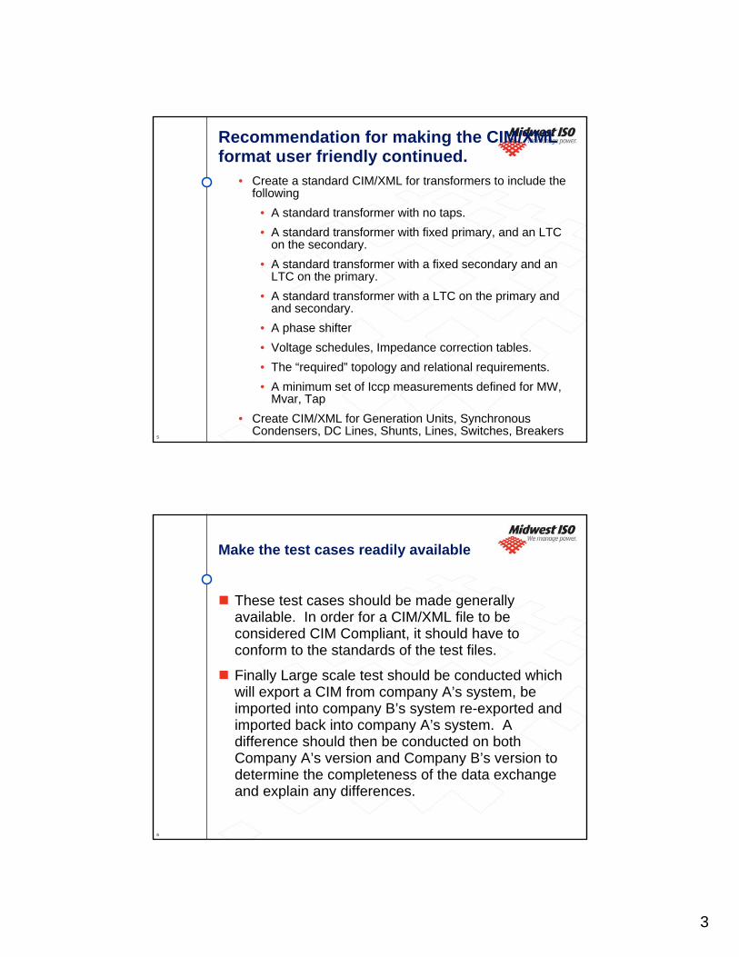
3
5
Recommendation for making the CIM/XML format user friendly continued.
• Create a standard CIM/XML for transformers to include the following
• A standard transformer with no taps.• A standard transformer with fixed primary, and an LTC
on the secondary.• A standard transformer with a fixed secondary and an
LTC on the primary.• A standard transformer with a LTC on the primary and
and secondary.• A phase shifter• Voltage schedules, Impedance correction tables.• The “required” topology and relational requirements.• A minimum set of Iccp measurements defined for MW,
Mvar, Tap• Create CIM/XML for Generation Units, Synchronous
Condensers, DC Lines, Shunts, Lines, Switches, Breakers
6
Make the test cases readily available
These test cases should be made generally available. In order for a CIM/XML file to be considered CIM Compliant, it should have to conform to the standards of the test files.
Finally Large scale test should be conducted which will export a CIM from company A’s system, be imported into company B’s system re-exported and imported back into company A’s system. A difference should then be conducted on both Company A’s version and Company B’s version to determine the completeness of the data exchange and explain any differences.

CIM COMPLIANCE REQUIREMENTS AND RECOMMENDATIONS
Enamul HaqSr. Engineer, EMS Services
California ISOFolsom, CA 95630November 1, 2005
Enamul Haq/ CAISO 2 9/26/05
CIM Compliance Requirements
Must be an Independent GroupAll parties must have no vendor responsibility or connection in any way.All parties must be completely free of any conflict of interest.
Must have real-world models to use in the compliance testMust have real tools to validate testMust validate that RDF IDs are persistent
Tests based on inputs from Utility Engineers.Must validate all aspects of standards – must include data issues and must provide 100% sample size for all CIM XML files verified to the CIM and Exchange standards (see next 2 slides for example data validation)

Enamul Haq/ CAISO 3 9/26/05
Sample Compliance Issues for Data Validation
Data Validation ExamplesFor “Voltage Control” Transformers the Type should not be set to “FIXED”.For “Regulating Transformers” the “Regulated” bus must be present.For “ACLineSegment” the “BaseVoltage” must be present.“For some Shunt Compensators the attribute “MVArPerSection” was set to Zero, but “NominalMvar” was populated.For some compensators the “CompensatorType” attribute was wrong ( series compensator was set to shunt).For some Regulating Shunt Compensators the Regulation Schedule was missing.For Shunt Compensators, the attribute “maximumSections” was set to zero.For Shunt Compensators, the attribute “normalSections” was was set greater than “maximumSections”.
Enamul Haq/ CAISO 4 9/26/05
Sample Compliance Issues for Data Validation - Continued
Data/Exporter IssuesThe unit of X-axis of “MVArCapabilityCurve” must be set to MW The Y-axis Type of some “MVArCapabilityCurve” must be set to “twoYValues”.Verify no “Orphan” Terminals get exported in the RDF files.In some model “lowVoltageLimit” and “highVoltageLimit” were associated with “voltageLevel” class, in other cases these were absent.In some models multiple “basePower” was specified.In some models “CimVersion” class was not specified.The attributes “minimumKV” and “maximumKV” were used for voltage regulation even if regulation voltage schedule is present in the model

Enamul Haq/ CAISO 5 9/26/05
RECOMMENDATION
Remove all ambiguity in the CPSM ProfileProvide clear explanation and usage instructions \in the CPSM documentUse CPSM profile for compliance testing in North AmericaCome up with a benchmark network model for compliance testing
Use the IEC Organization to Ensure ComplianceIEC would certify the tests and oversee the execution of the tests.IEC would ensure no conflict of interest exists in the testing environment or with those performing the testIEC would issue certificates of compliance for ProductsIf possible, they would appoint IEC personnel to conduct the tests
1
1
Thoughts On Compliance TestingTerry Saxton
EPRI CIM/GID International Conference MISO, Indianapolis
November 2005
© 2003-2004 Xtensible Solutions, Inc. 2
Levels of Conformance
• Transport• Syntax / form / structure• Content• Scenario/process• Interoperable with other solutions• Implementation Testing for Project
2
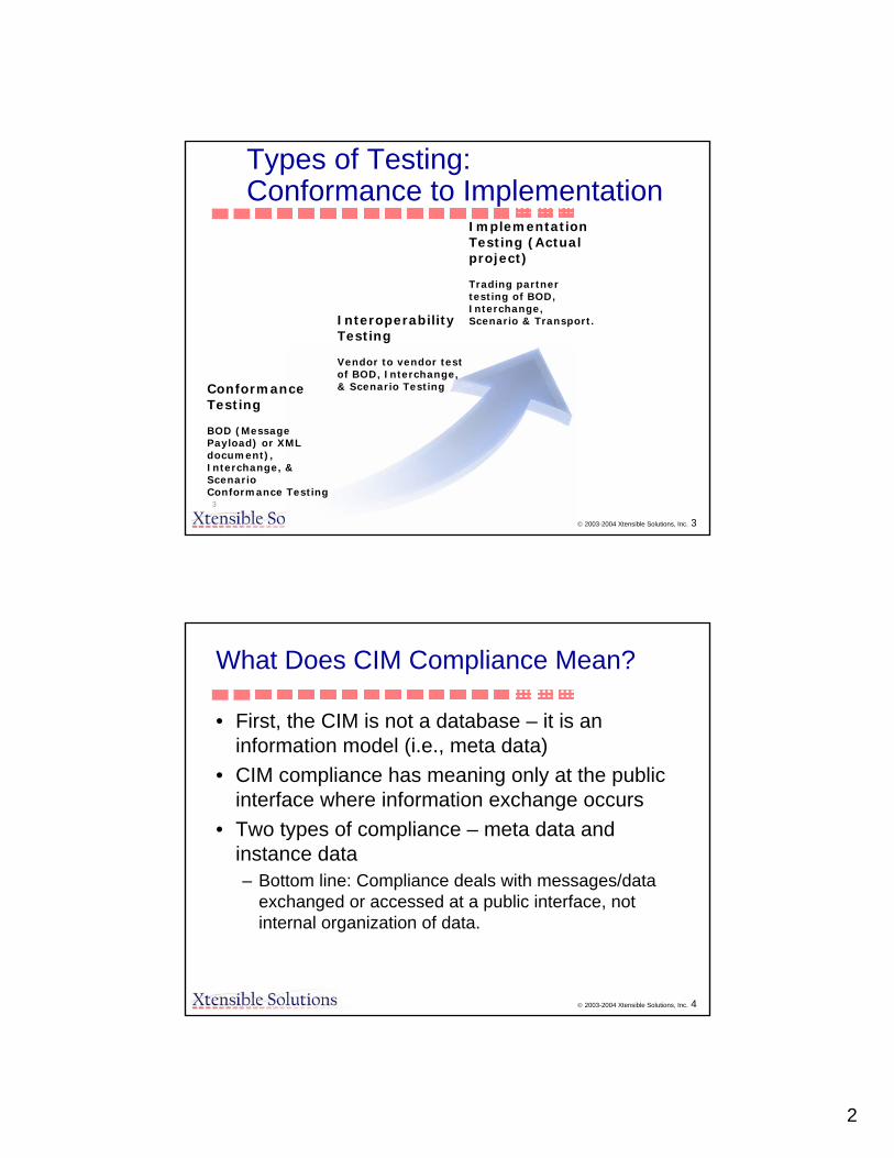
2
© 2003-2004 Xtensible Solutions, Inc. 3
Types of Testing:Conformance to Implementation
Conformance Testing
BOD (Message Payload) or XML document), Interchange, & Scenario Conformance Testing
Interoperability Testing
Vendor to vendor test of BOD, Interchange, & Scenario Testing
Implementation Testing (Actual project)
Trading partner testing of BOD, Interchange, Scenario & Transport.
3
© 2003-2004 Xtensible Solutions, Inc. 4
What Does CIM Compliance Mean?
• First, the CIM is not a database – it is an information model (i.e., meta data)
• CIM compliance has meaning only at the public interface where information exchange occurs
• Two types of compliance – meta data and instance data– Bottom line: Compliance deals with messages/data
exchanged or accessed at a public interface, not internal organization of data.
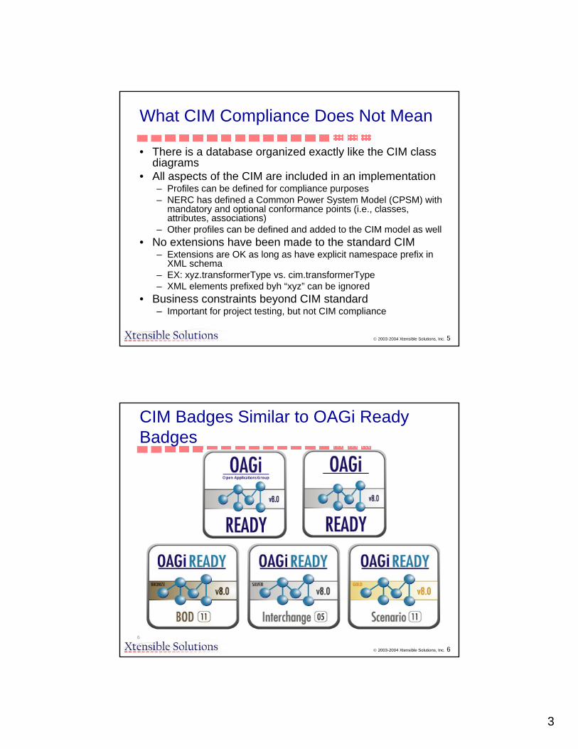
3
© 2003-2004 Xtensible Solutions, Inc. 5
What CIM Compliance Does Not Mean
• There is a database organized exactly like the CIM class diagrams
• All aspects of the CIM are included in an implementation– Profiles can be defined for compliance purposes– NERC has defined a Common Power System Model (CPSM) with
mandatory and optional conformance points (i.e., classes, attributes, associations)
– Other profiles can be defined and added to the CIM model as well• No extensions have been made to the standard CIM
– Extensions are OK as long as have explicit namespace prefix in XML schema
– EX: xyz.transformerType vs. cim.transformerType– XML elements prefixed byh “xyz” can be ignored
• Business constraints beyond CIM standard– Important for project testing, but not CIM compliance
© 2003-2004 Xtensible Solutions, Inc. 6
CIM Badges Similar to OAGi Ready Badges
6
1
CIM User Group Status and Plans
Greg Congleton - TVAEPRI CIM/GID SeminarMISO Carmel, Indiana
November 2, 2005
CIM User Group Status and Plans
Greg Congleton EPRI CIM/GID Seminar MISO Carmel, Indiana November 2, 2005 210/21/2005 Slide 2
• Information technology trends support application integration and semantic consistency both within the enterprise and with trading partners.
• These trends go beyond exchange of network models or updates to network models.
• Transactional messages about CIM concepts and events that touch on CIM concepts will need to be designed and coordinated for semantic and syntactic consistency.
MOTIVATION

2
CIM User Group Status and Plans
Greg Congleton EPRI CIM/GID Seminar MISO Carmel, Indiana November 2, 2005 310/21/2005 Slide 3
•The objective of the CIM User Group (CIMug) is to ensure that the affected parties have the means to coordinate these developments in an efficient and effective manner.
•The CIMug will be the primary means for developing consensus and consistency across the industry as well as managing and communicating issues concerning the CIM model.
Objective
CIM User Group Status and Plans• Table 1, CIMug Prioritized Objectives.A. CIM Knowledge/Artifact Exchange 43% • Forum for all CIM users• Share artifacts derived from standards• Promote interest in and use of CIM and related
standards• Share user experiences• Clearinghouse for CIM related questions• Provide training materials• Conduct workshops• Electronic newsletter• Lists of CIM-compliant products• Provide product advertising opportunities
Greg Congleton EPRI CIM/GID Seminar MISO Carmel, Indiana November 2, 2005 410/21/2005 Slide 4

3
CIM User Group Status and Plans• Table 1, CIMug Prioritized Objectives - continued.
B. CIM Model Management, Maintenance, and Methodology 27% • CIM editor funding support• CIM XML tool maintenance
C. Test support 20% • Compliance test support• Interoperability test support – CIM XML, GID, XML messages• Form partnerships for exchanging CIM-compliant messages
D. Harmonization 10%• Integration, harmonization and coordination with other standards
Greg Congleton EPRI CIM/GID Seminar MISO Carmel, Indiana November 2, 2005 510/21/2005 Slide 5
CIM User Group Status and Plans
Greg Congleton EPRI CIM/GID Seminar MISO Carmel, Indiana November 2, 2005 610/21/2005 Slide 6
• The abstract nature of the CIM leads to flexibility and competing demands on its enhancement. Because of this a CIMug needs both an open forum where these enhancements can be arbitrated as well as committed management of the model artifacts supported by durable organizational knowledge about its evolution.
• The CIMug must serve vendors who produce and market CIM compliant products, consulting firms who support the understanding and use of the CIM, and utility and energy companies using CIM compliant products and applying CIM concepts and artifacts to their information management practices
Objective

4
CIM User Group Status and Plans
Greg Congleton EPRI CIM/GID Seminar MISO Carmel, Indiana November 2, 2005 710/21/2005 Slide 7
UCA International Users Group Organization
BOARD OF DIRECTORS
TECHNICAL OVERSIGHT COMMITTEE
Harmonization
OPERATING OFFICERS
Technical Publications
IEC 61850
Testing
Help DeskEXECUTIVE COMMITTEE
Liaison
Marketing
Membership
MEMBERS ADVISORS
CIM
Distributed Resourses
CIM User Group Status and Plans
Greg Congleton EPRI CIM/GID Seminar MISO Carmel, Indiana November 2, 2005 810/21/2005 Slide 8
CIM User Group Task ForceFormed after January 2005 meeting at TVA
Membership:Jay Britton, ARVEA, IncGreg Congleton, TVAEd Dobrowolski, KEMA ConsultingThierry Godart, AREVA, IncAndre Maizener, EDFScot Neumann, UISOLHugo Reyes, SCETerry Saxton, Xtensible SolutionsShigetaka Kikkawa, SCEJames G. Waight, Siemens

5
CIM User Group Status and Plans
Greg Congleton EPRI CIM/GID Seminar MISO Carmel, Indiana November 2, 2005 910/21/2005 Slide 9
1. Negotiations with UCAIUG Board and Officers via email, phone calls 2. and a meeting in Columbus, Ohio May 2005.
3. UCAIUG Board votes to accept CIMug TF changes to their charter, bylaws.
4. UCAIUG Board votes to fund CIMug activities.
5. First Organizational Meeting at Exelon – Chicago August 2005• Issues list developed• Web site requirements developed – written up by Scott Nuemann• Nomination and voting procedures set for initial positions
CIM User Group Status and Plans
Greg Congleton EPRI CIM/GID Seminar MISO Carmel, Indiana November 2, 2005 1010/21/2005 Slide 10
Voting and Nomination Results
Executive Committee 3 additional “CIM” members
Technical Oversight Committee 1 at large memberDean Hengst – Exelon
CIM Model Manager 1 year rotational position among vendorsAlso member of the Harmonization Committee
Kurt Hunter – Siemens
CIM Technical Committee Co-Chairs – 1 Utility 1 VendorAlso members of the Technical Oversight Committee
Greg Congleton – TVATerry Saxton – Xtensible Solutions

6
CIM User Group Status and Plans
Greg Congleton EPRI CIM/GID Seminar MISO Carmel, Indiana November 2, 2005 1110/21/2005 Slide 11
Volunteering Results
Marketing Committee any number of additional membersMay form a Sub-Committee focused on marketing CIM
• Dave Becker - EPRI
• Greg Robinson - Xtensible
CIM Technical Committee any number of additional members• Randy Curtis, WAPA Rocky Mountain Region• Dave Becker - EPRI• Erich Wuergler - Siemens• John Gillerman - SISCO • Heather Forsythe - PJM• Mike Nazarek - PJM• Suzanne Caron-André - SNC-Lavalin Energy Control Systems• David Brown - SNC-Lavalin Energy Control Systems• Jay Britton - AREVA• others - AREVA • Terry Saxton - Xtensible• Greg Robinson - Xtensible • Joe Zhou - Xtensible • Harry Garton - Xtensible • Greg Congleton - TVA• Mark E. Browning - Exelon• Lars-Ola Osterlund - ABB• Ed Dobrowolski - KEMA • Others from UISOL, PacifiCorp, etc
CIM User Group Status and Plans
Greg Congleton EPRI CIM/GID Seminar MISO Carmel, Indiana November 2, 2005 1210/21/2005 Slide 12
PLANSMeetings•Meet as the CIM Technical Committee at least once a year, usually in conjunction with the UCAIUG meeting or with a large T&D conference. ••Meetings will be for sharing of results, defining issues and conducting some of the administrative business of the group.
•During the first year(s) more than 1 meeting a year may be called for.

7
CIM User Group Status and Plans
Greg Congleton EPRI CIM/GID Seminar MISO Carmel, Indiana November 2, 2005 1310/21/2005 Slide 13
PLANS
Working Groups1. Form working groups focused on CIM issues of interest
and importance to the membership. 2. Working groups define issue scope, resolution plan and
deliverable.3. Working groups work and coordinate between face to
face meetings.4. Working groups are for peer review of issue resolution.5. Working groups deliver products to wider membership
for review, use, acceptance and delivery where appropriate to the IEC working groups.
CIM User Group Status and Plans
Greg Congleton EPRI CIM/GID Seminar MISO Carmel, Indiana November 2, 2005 1410/21/2005 Slide 14
PLANSCIM Model manager (CMM) and CIM issue resolutionKurt covered this yesterday
Help Desk
• Staff an email list of people with CIM expertise willing to answer questions.
• Questions will be submitted via the web site and then allocated to experts by a help desk monitor or may be automatically distributed to those on the CIM help desk distribution list.
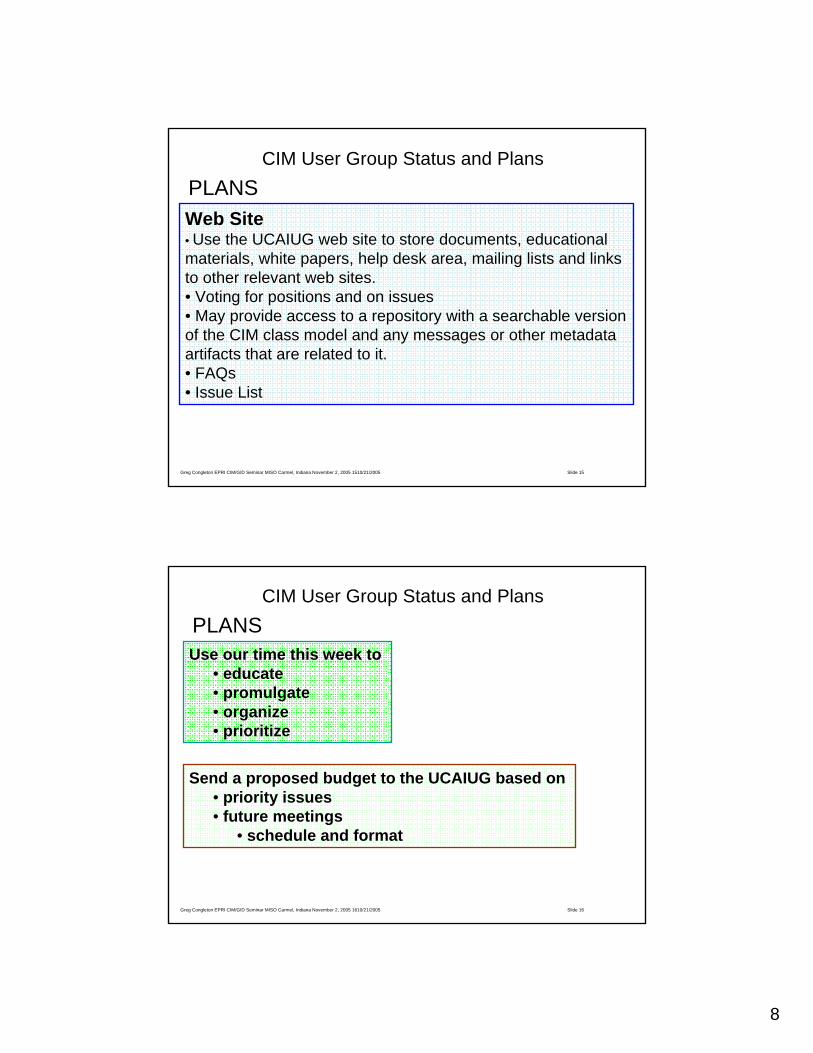
8
CIM User Group Status and Plans
Greg Congleton EPRI CIM/GID Seminar MISO Carmel, Indiana November 2, 2005 1510/21/2005 Slide 15
PLANSWeb Site• Use the UCAIUG web site to store documents, educational materials, white papers, help desk area, mailing lists and linksto other relevant web sites.• Voting for positions and on issues• May provide access to a repository with a searchable version of the CIM class model and any messages or other metadata artifacts that are related to it.• FAQs• Issue List
CIM User Group Status and Plans
Greg Congleton EPRI CIM/GID Seminar MISO Carmel, Indiana November 2, 2005 1610/21/2005 Slide 16
PLANSUse our time this week to
• educate• promulgate• organize• prioritize
Send a proposed budget to the UCAIUG based on • priority issues • future meetings
• schedule and format

9
CIM User Group Status and Plans
Greg Congleton EPRI CIM/GID Seminar MISO Carmel, Indiana November 2, 2005 1710/21/2005 Slide 17
??????
•Use Thursday and Friday to form working groups that will address some of our most pressing issues.
•These working groups will continue to work after this week.
CIM User Group Processes
Issues from the August 2005 meeting
Greg Congleton EPRI CIM/GID Seminar MISO Carmel, Indiana November 2, 2005 1810/21/2005 Slide 18

10
The CIM processes were split up into 3 separate items with a small breakout group to discuss each:
1. Web site/Repository requirements2. Technical Issues List/Help Desk process 3. Marketing of CIM & the CIM UG
Greg Congleton EPRI CIM/GID Seminar MISO Carmel, Indiana November 2, 2005 1910/21/2005 Slide 19
CIM User Group Processes
Web site/RepositoryThe web site should have
repository/archiving capability. 1. What types of artifacts need to be
stored?2. What search capability is needed? 3. Scott Nuemann has created a draft
requirements document. It has been forwarded to Kay at UCAIUG.
Greg Congleton EPRI CIM/GID Seminar MISO Carmel, Indiana November 2, 2005 2010/21/2005 Slide 20
CIM User Group Processes

11
Technical Issues List/Help Desk process1. The Help Desk should be a two level function.
– Level 1 is for questions and simple research items. – Level 2 is for dealing with issues.
2. A process will need to be established and a liaison with the CMM will be required to handle issues.
3. Issue resolution needs to be slotted to specific releases of the CIM.
4. Testing of new releases and the identifying and assessing the effect on interfaces is required.
Greg Congleton EPRI CIM/GID Seminar MISO Carmel, Indiana November 2, 2005 2110/21/2005 Slide 21
CIM User Group Processes
Marketing of CIM & the CIM UG1. The message needs to be focused to the specific technology:
– CIM– IEC61850 (Substation Automation)– Open AMI/Open DR (Demand Response)– One for the overall group
2. Some thought that users don’t drive the group, but others won’t join without a strong user presence. Therefore, marketing needs to be targeted to users.
3. Several levels need to be addressed:– Operations – Need to be sold on the technology and that for those implementing
the technology joining the group has significant benefits.– Executives – Need support to justify the operations desire to take part. Would like
to target these…but how? Perhaps using:• NERC, EEI, FERC
4. There are various events at which we might be able to promote the group.5. We need to staff the marketing subcommittee and possibly a CIM UG Marketing Task
Force. This is an urgent need.6. Chair of a CIM UG Marketing TF – Probably from a vendor to drive the group, schedule
meetings, set objectives, etc. In general, this person will need to make stuff happen. 7. Utility Co-chair of the Marketing Subcommittee – Dave and Bhavin will inquire within
EPRI members for a new marketing co-chair for the SC. 8. There may be a need for different marketing in Europe as opposed to the US.
Greg Congleton EPRI CIM/GID Seminar MISO Carmel, Indiana November 2, 2005 2210/21/2005 Slide 22
CIM User Group Processes

12
• Please pick one of these areas and give some thought, time and energy to help get these processes established.
1. Web site/Repository/Help Desk interface2. Technical Issues List/Help Desk process 3. Marketing of CIM & the CIM UG
Greg Congleton EPRI CIM/GID Seminar MISO Carmel, Indiana November 2, 2005 2310/21/2005 Slide 23
CIM User Group Processes
Greg Congleton EPRI CIM/GID Seminar MISO Carmel, Indiana November 2, 2005 2410/21/2005 Slide 24
??????
• One of the working groups will address User group• Processes • Issues
• These working groups will continue to work after this week.
CIM User Group Processes

1
PTD Energy Management & Information Systems
CIM IssuesGreg Congleton
Siemens Power Transmission & Distribution, Inc.Energy Management & Automation
08-1-2005 2
Current Status of WG13 CIM Issues
Total of 303 logged issues
196 Completed49 In Process58 To Be Reviewed

2
Siemens Power Transmission & Distribution, Inc.Energy Management & Automation
08-1-2005 3
Current Status of WG13 CIM Issues
“In Process” Issues categories include:
Documentation Changes
Waiting for Detailed Proposals or Use Cases
Checking with other WG’s
Proposals Under Review
Major Issues
Siemens Power Transmission & Distribution, Inc.Energy Management & Automation
08-1-2005 4
Current Status of WG13 CIM Issues
Proposals Under Review
Split of Compensator class into two classes ShuntCompensator and SeriesCompensator
DC Line Model (currently incomplete)

3
Siemens Power Transmission & Distribution, Inc.Energy Management & Automation
08-1-2005 5
Major Issues
Equipment Naming/Hierarchies Issues
Differentiate owner and operator of resourcesClearly defined naming hierarchiesClarify situations where multiple possible
parents exist and at least one parent is mandatory
Siemens Power Transmission & Distribution, Inc.Energy Management & Automation
08-1-2005 6
Major Issues
Time Issues
Need clearly defined format for date and timeNeed time series model (event oriented)Clarify how to define time on X-Axis of a
CurveScheduleChange/Correct time based primitive data
types

4
Siemens Power Transmission & Distribution, Inc.Energy Management & Automation
08-1-2005 7
Major Issues
Data Typing Issues
Clean up Numeric data typeClearly define all primitive data types (add
documentation)Clarify all UML DataTypesAdd string, decimal, and integer as primitive
data types
Siemens Power Transmission & Distribution, Inc.Energy Management & Automation
08-1-2005 8
Major Issues
Line Containment Issues
Containment needed for line related resources outside of SubstationsIn distribution network a ConnectivityNodedoes not have an explicit EquipmentContainerNeed better modeling for tapped lines

5
Siemens Power Transmission & Distribution, Inc.Energy Management & Automation
08-1-2005 9
Major Issues
SI Units Issues
IEC requires use of base SI units (i.e. volts, not kV; watts, not MW, etc.) Affects attribute data types, attribute names
(ratedMVA, initialMW, etc.)
Siemens Power Transmission & Distribution, Inc.Energy Management & Automation
08-1-2005 10
Interoperability Issues
Exchange profile defined too flexiblyMultiple options for containment hierarchyMultiple options to represent equipment (e.g. series devices can be specified as either a Compensator or an ACLineSegment)
Exchange profile does not clearly define required and optional attributes and associationsUse of Abstract classes should be discouragedWhat side (UML role) to use in an association is not clear