NETWORK LIFETIME EXTENSION BASED ON NETWORK CODING TECHNIQUE IN UNDERWATER ACOUSTIC SENSOR NETWORKS
16
International Journal of Distributed and Parallel Systems (IJDPS) Vol.3, No.3, May 2012 DOI : 10.5121/ijdps.2012.3309 85 NETWORK L IFETIME EXTENSION B ASED ON NETWORK C ODING T ECHNIQUE I N UNDERWATER A COUSTIC S ENSOR NETWORKS Padmavathy.T.V, Gayathri.V, Indumathi.V, Karthika.G Department of Electronics and Communication Engineering, RMK College of Engineering And Technology Email:[email protected] ABSTRACT Underwater acoustic sensor networks (UWASNs) are playing a lot of interest in ocean applications, such as ocean pollution monitoring, ocean animal surveillance, oceanographic data collection, assisted- navigation, and offshore exploration, UWASN is composed of underwater sensors that engage sound to transmit information collected in the ocean. The reason to utilize sound is that radio frequency (RF) signals used by terrestrial sensor networks (TWSNs) can merely transmit a few meters in the water. Unfortunately, the efficiency of UWASNs is inferior to that of the terrestrial sensor networks (TWSNs). Some of the challenges in under water communication are propagation delay, high bit error rate and limited bandwidth. Our aim is to minimize the power consumption and to improve the reliability of data transmission by finding the optimum number of clusters based on energy consumption. KEYWORDS Acoustic Sensor Networks, Buffer Length, Energy Consumption, NS-2.26, optimum cluster size 1. INTRODUCTION The research of Under Water Acoustic Sensor Network (UWASN) is attracting due to their important under water application for military, emergency and commercial purpose. The underwater environment is much different from terrestrial environment. Due to the high dense salty water the EM wave cannot be transmitted for long distance in the ocean [1]. This is because of high attenuation and absorption effect in under water environment. To overcome this problem acoustic sensors can be used which will provide a better communication in under water environment. Even the optical signal gets scattered and absorbed by the underwater because it can’t travel to a long distance in salty water. Due to scattering and adsorption of signal in under water communication the signal attenuated. Some of the challenges in under water communication are propagation delay, high bit error rate and limited bandwidth. In this harsh environment to provide low energy consumption we proposed a protocol to overcome the challenges in UWC. The main objective of this paper is to minimize the power consumption and to improve the reliability of data transmission. Instead of transmitting data from source to sink directly if we use clustering method, it will lead better energy consumption in UWC. The UWSN has large number of sensor nodes. These nodes are grouped as several clusters based on the following costs.1) Energy level 2) Buffer length 3) Distance between the nodes. Each associate node in a cluster passes the data to a cluster head, and then the data is transmitted to sink through the cluster heads. The cluster head is selected in random manner in each transmission phase.
-
Upload
independent -
Category
Documents
-
view
2 -
download
0
Transcript of NETWORK LIFETIME EXTENSION BASED ON NETWORK CODING TECHNIQUE IN UNDERWATER ACOUSTIC SENSOR NETWORKS
International Journal of Distributed and Parallel Systems (IJDPS) Vol.3, No.3, May 2012
DOI : 10.5121/ijdps.2012.3309 85
NETWORK LIFETIME EXTENSION BASED ON
NETWORK CODING TECHNIQUE IN UNDERWATER
ACOUSTIC SENSOR NETWORKS
Padmavathy.T.V, Gayathri.V, Indumathi.V, Karthika.G
Department of Electronics and Communication Engineering,
RMK College of Engineering And Technology Email:[email protected]
ABSTRACT
Underwater acoustic sensor networks (UWASNs) are playing a lot of interest in ocean applications, such
as ocean pollution monitoring, ocean animal surveillance, oceanographic data collection, assisted-
navigation, and offshore exploration, UWASN is composed of underwater sensors that engage sound to
transmit information collected in the ocean. The reason to utilize sound is that radio frequency (RF)
signals used by terrestrial sensor networks (TWSNs) can merely transmit a few meters in the water.
Unfortunately, the efficiency of UWASNs is inferior to that of the terrestrial sensor networks (TWSNs).
Some of the challenges in under water communication are propagation delay, high bit error rate and
limited bandwidth. Our aim is to minimize the power consumption and to improve the reliability of data
transmission by finding the optimum number of clusters based on energy consumption.
KEYWORDS
Acoustic Sensor Networks, Buffer Length, Energy Consumption, NS-2.26, optimum cluster size
1. INTRODUCTION
The research of Under Water Acoustic Sensor Network (UWASN) is attracting due to their
important under water application for military, emergency and commercial purpose. The
underwater environment is much different from terrestrial environment. Due to the high dense
salty water the EM wave cannot be transmitted for long distance in the ocean [1]. This is
because of high attenuation and absorption effect in under water environment. To overcome
this problem acoustic sensors can be used which will provide a better communication in under
water environment. Even the optical signal gets scattered and absorbed by the underwater because it can’t travel to a long distance in salty water. Due to scattering and adsorption of
signal in under water communication the signal attenuated. Some of the challenges in under
water communication are propagation delay, high bit error rate and limited bandwidth. In this
harsh environment to provide low energy consumption we proposed a protocol to overcome the
challenges in UWC.
The main objective of this paper is to minimize the power consumption and to improve the
reliability of data transmission. Instead of transmitting data from source to sink directly if we
use clustering method, it will lead better energy consumption in UWC. The UWSN has large number of sensor nodes. These nodes are grouped as several clusters based on the following
costs.1) Energy level 2) Buffer length 3) Distance between the nodes. Each associate node in a
cluster passes the data to a cluster head, and then the data is transmitted to sink through the
cluster heads. The cluster head is selected in random manner in each transmission phase.

International Journal of Distributed and Parallel Systems (IJDPS) Vol.3, No.3, May 2012
86
2. UWASN ARCHITECTURE
There are several different architectures for Underwater Acoustic Sensor Networks, depending
on the applications. They are: Static Architecture, Hybrid Architectures and Mobile UASNs and Free Floating Networks.
2.1. Static Architecture
For static architecture, the network topology would be in relative static state after sensors were
deployed, the network could be anchored into two-dimensional (2D) or three-dimensional (3D)
either on the sea floor or surface. The main character of this architecture is that the topology
does not change or with neglectable movements after deployment. In 2D case, the topology
could be grid, cluster, tree, or line-relay deployment same as terrestrial WSNs. These are
constituted by sensor nodes that are anchored to the bottom of the ocean. Typical applications
may be environmental monitoring, or monitoring of underwater plates in tectonics. In 3D case,
sensors could be moored to anchors on ocean floor or to surface floats with fix depth.
2.2. Two-dimensional Underwater Sensor Networks
Figure 1. Two-dimensional Underwater Sensor Networks
Figure 1 shows reference architecture for two-dimensional underwater acoustic sensor
networks. A group of sensor nodes are anchored to the bottom of the ocean with deep ocean
anchors. By means of wireless acoustic links, underwater sensor nodes are interconnected to
one or more underwater sinks, which are network devices in charge of relaying data from the ocean bottom network to a surface station. To achieve this objective, under water sinks are
equipped with two acoustic transceivers, namely a vertical and a horizontal transceiver. The
horizontal transceiver is used by the sink to communicate with the sensor nodes in order to i)
send commands and configuration data to the sensors ii) collect monitored data s to sink. The
vertical link is used by the sinks to relay data to a surface station. Vertical transceivers must be
long range transceivers for deep water applications as the ocean can be as deep as 10 km. The

International Journal of Distributed and Parallel Systems (IJDPS) Vol.3, No.3, May 2012
87
surface station is equipped with an acoustic transceiver that is able to handle multiple parallel
communications with the deployed sinks.
Sensors can be connected to sinks via direct links or through multi-hop paths. In the former
case, each sensor directly sends the gathered data to the selected sink. This is the simplest
way to network sensors, but it may not be the most energy efficient, since the sink may be far
from the node and the power necessary to transmit may decay with powers greater than two
of the distance. Furthermore, direct links are very likely to reduce the network throughput
because of increased acoustic interference due to high transmission power. In case of multi-
hop paths, as in terrestrial sensor networks, the data produced by a source sensor is relayed
by intermediate sensors until it reaches the sink. This results in energy savings and increased
network capacity, but increases the complexity of the routing functionality as well.
2.3. Three-dimensional Underwater Sensor Networks
Figure 2. Three-dimensional Underwater Sensor Networks
Figure 2 shows the three dimensional under water sensor networks. Three dimensional
underwater networks are used to detect and observe phenomena that cannot be adequately
observed by means of ocean bottom sensor nodes, i.e., to perform cooperative sampling of the
3D ocean environment. In three-dimensional underwater networks, sensor nodes float at
different depths in order to observe a given phenomenon. One possible solution would be to
attach each under water sensor node to a surface buoy, by means of wires whose length can be
regulated so as to adjust the depth of each sensor node. However, although this solution allows
easy and quick deployment of the sensor network, multiple floating buoys may obstruct ships
navigating on the surface, or they can be easily detected and deactivated by enemies in military
settings.
For these reasons, a different approach can be to anchor sensor devices to the bottom of the ocean. In this architecture, depicted in the figure above, each sensor is anchored to the ocean
bottom and equipped with a floating buoy that can be inflated by a pump. The buoy pushes the
sensor towards the ocean surface. The depth of the sensor can then be regulated by adjusting
the length of the wire that connects the sensor to the anchor, by means of an electronically
controlled engine that resides on the sensor.

International Journal of Distributed and Parallel Systems (IJDPS) Vol.3, No.3, May 2012
88
2.4. Hybrid Architectures
Figure 3. Hybrid architecture
Figure 3 shows the Hybrid architecture of underwater acoustic sensor networks. Hybrid
Architecture of UASN consists of lots of static sensors together with some mobile sensors. In hybrid architecture, mobile nodes play a key role for additional support in accomplishing task,
perhaps for data harvesting or enhancing the network capacity. Mobile nodes could be
considered as super nodes which has more energy and can move independently, and it could be
a router between fixed sensors, or a manager for network reconfiguration, or even a normal
sensor for data sensing. The mobile nodes can be AUVs, which equipped with two transceivers,
in horizontal and vertical direction. With the help of mobile nodes, the network can realize 3D
surveillance, and adjust the topology to meet the application demand. Mobile nodes can also optimize the deployment to maximize network capacity, and ensure the reliability when some
sensors lose their function.
2.5. Mobile UASNs and Free Floating Networks
Figure 4. Mobile UASNs with free-floating networks
In this architecture, all the nodes are not restricted geographically, nodes can move freely, and
the network topology would be variable. Figure 2.4 shows a normal architecture, it could be
divided into two layers; surface layer sensors often equipped with a wireless transceiver for
International Journal of Distributed and Parallel Systems (IJDPS) Vol.3, No.3, May 2012
89
data communication, and are usually used for pollution detecting, water quality surveillance,
coastal circulation monitoring and pollutant tracking. Underwater layer consists of many
mobile nodes which can stay at any depth with the help of flotative equipment; it can be used
for ocean investigation, fish migration and biological monitoring. Unlike the active behavior of
mobile nodes, the sensors movement is passive; the dynamic ocean characters (such as waves,
tides, currents) play a key role on the nodes movement.
A majority of this kind of architecture is passive network; the topology would be changed
according to the integrated effect of currents, winds, tides, and waves. This brings the biggest
disadvantage that the coverage and communication link could not be guaranteed, and it is
difficult to achieve effective topology control. The interesting characteristic of this architecture
is that it can track objects moving with water currents without any manual interference. For the
scenarios that mobile UASN works together with free floating sensor network, communication
connection is needed between under water layer and surface layer, this calls for some free
floating sensors on the surface should be equipped with acoustic modem, also under water
autonomous mobile nodes is needed for keeping active data link.
3. RELATED WORK
In this paper [1], several fundamental key aspects of underwater acoustic communications are
investigated. Different architectures for two-dimensional and three-dimensional underwater
sensor networks are discussed, and the characteristics of the underwater channel are detailed.
The main challenges for the development of efficient networking solutions posed by the
underwater environment are detailed and a cross-layer approach to the integration of all
communication functionalities is suggested. Furthermore, open research issues are discussed
and possible solution approaches are outlined.
Network coding is a technique where, instead of simply relaying the packets of information
they receive, the nodes of a network will take several packets and combine them together for
transmission. This can be used to attain the maximum possible information flow in a network.
Network coding is a field of information theory and coding theory. Network coding can
improve throughput, robustness, complexity, and security [2].
In [3] this paper they proposed UWMAC, a transmitter-based CDMA MAC protocol for
UWASNs that incorporates a novel closed-loop distributed algorithm to set the optimal transmit
power and code length to minimize the near-far effect. UW-MAC aims at achieving three objectives such as high network throughput, low channel access delay, and low energy
consumption. It is proven that UW-MAC manages to simultaneously achieve high network
throughput, limited channel access delay, and low energy consumption in deep water
communications, which are not severely affected by multipath.
Fatma Bouabdallah and Raouf Boutaba proposed UW-OFDMAC, a distributed Medium Access
Control (MAC) protocol which provides low energy consumption and high bandwidth. By
limiting Subcarrier Spacing f∆ and Guard Interval gT they have proved that the low energy
consumption can be acheived. Subcarrier Spacing should be chosen so that the sub-carriers are orthogonal to each other, meaning that cross-talk between the sub-carriers is eliminated or in
other words Inter-Carrier interference (ICI) is avoided. Guard Interval is inserted to avoid inter
symbol interference. A large number of closely spaced orthogonal sub-carrier signals to carry
data. The data is divided into several parallel data streams or channels, one for each sub-
carrier[4].
The authors proposed a new multi-path routing algorithm, which taking the distance and energy
into account to determine the transmission path. The algorithm balances the energy consumption of network, prolong the network’s lifetime and improve energy efficiency. HMR-
LEACH algorithm put the energy on the first priority when chooses the transmission path.

International Journal of Distributed and Parallel Systems (IJDPS) Vol.3, No.3, May 2012
90
HMR-LEACH algorithm would reduce the single path to energy depletion phenomenon,
extending the network lifetime Period. Sink broadcast control package first in a frequency to
determine the adjacent clusters, which refer to cluster that directly transfer converged data to
Sink. Then the adjacent clusters broadcast its own color coded information to non-adjacent
cluster in the same frequency and continue to broadcast until the broadcast coverage of the
entire network. If a cluster has received only one color-coded, it shows that the cluster has only
one path leading to base station. If receive multiple color-coded, indicating that the cluster can
be multi-paths to transfer data to sink nodes [5].
Based on analysis of energy consumption for LEACH in underwater channel, the authors
proposed a novel scheme for cluster-head selection to ensure nodes energy load balance by
considering residual energy of candidate nodes and the distance to SINK. A cluster based
network can be partitioned into disjoint clusters. Each cluster consists of one cluster head and
multiple member nodes. Each cluster head collects data from its member nodes and relays the
processed data. Based on the energy analysis of LEACH protocol in underwater channel, a
clustering scheme for selecting and putting sensor nodes into operation in each round is also
proposed by using a time metric, according which the nodes over the network broadcast ADV,
to ensure the node with more energy to become cluster head. Then it avoids choosing nodes
with lower residual energy and bad position as cluster-heads and then provides the energy
load’s proportionality of sensor node [6].
In [7], they propose a novel energy efficient MAC protocol named NOGO-MAC (Node
Grouped OFDMA MAC) which is based on orthogonal frequency division multiple accesses
(OFDMA) and exploit the physical characteristic that propagation loss of acoustic wave
depends on the distance more heavily at high frequency than at low frequency. In the proposed
scheme, sensor nodes are grouped according to the distance to sink node. Then, each group uses
a different frequency band in such a way that sensor nodes which are closer to the sink node use
higher frequency band and farther ones use lower frequency band. The proposed scheme not
only enables all sensor nodes to maintain the signal-to-noise ratio above a certain required
level, but also reduces overall transmission power consumption. In addition, an adaptive sub-channel allocation is employed in order to improve data transmission rate.
In a wireless sensor network the sensor nodes are divided into several clusters according to the
position of the sink. Initially, a sensor node in the cluster is elected randomly as the cluster
head. Periodically, the sensor nodes in the same cluster will send its data to the head. The head
aggregates the collected data and then, send these data directly to the sink. The procedure that
sensor nodes sent the data to the head, the head aggregated the collected data and then, sent
these data directly to the sink is termed as a round. After a round, each cluster will select a new head. Maximal-energy method selects a head which contains the maximal energy of this cluster
[8].
In [9] the authors investigate the selection of CHs in a distributed environment such as
MANET. They derives new results on the algorithmic complexity of two variants of the CH
selection: distance-constrained and size-constrained clustering. The first variant i.e distance-
constrained selects a set of CHs such that every node in the network is either a CH or is located
within distance h hops away from the nearest CH. The second variant i.e. size-constrained
limits the maximum size of each cluster to members. A third variant, combining the distance
and size constraints, is also presented. The distance-constrained CH selection can find a smaller
CH set compared to the distance-and-size-constrained selection.
In this paper, a novel, token-based medium access control (TMAC) solution for underwater
acoustic broadcast is introduced. TMAC provides a solution to the synchronization problem,
ensuring effective communication. TDMA protocols divide a time interval known as a frame
into time slots. Each time slot is assigned to a communication source. TDMA protocols in

International Journal of Distributed and Parallel Systems (IJDPS) Vol.3, No.3, May 2012
91
underwater acoustic networks require strict synchronization. This TMAC solution avoids the
need for synchronization and therefore underwrites successful communication [10].
Borja Peleato and Milica Stojanovic proposed Distance-Aware Collision Avoidance Protocol
(DACAP) a non-synchronized protocol that allows a node to use different hand-shake lengths
for different receivers so as to minimize the average handshake duration. This is achieved by
taking advantage of both the greater received power over short links, and the estimated distance
between the nodes. DACAP is a collision avoidance protocol that is easily scalable to the
changing number of nodes and the coverage area of the network, and can be optimized for a
particular network with very few constraints on the nodes. And it provides higher throughput
than Slotted FAMA with similar power efficiency [11].
In [12] this paper, deployment strategies of underwater sensor nodes and gateway nodes for
two-dimensional communication architecture in
Underwater Acoustic Wireless Sensor Networks (UWSNs) are proposed. In the
sensor deployment strategy, underwater sensor nodes are deployed in two rows along the
coastline, which is of complete coverage and connectivity, localization available and scalable. In the gateway deployment strategy, the gateway deployment is modelled as an optimization
problem, by finding the locations of underwater gateway nodes required to achieve a given
design objective, which can be minimal expected delay and minimal expected energy
consumption. The authors measure the performance of the strategies by extensive simulations
using the OPNET network simulator.
The coverage and connectivity are important standards of the sensor deployment strategies in
underwater acoustic wireless sensor networks (UWSNs). In [13] this paper, the authors mainly research on the deployment of underwatersensors in UWSNs. The advantages and
disadvantages of some existing algorithms are analysed and an improved algorithm is provided,
which can achieve the complete coverage and connectivity. Further more, combining with the
problem of localization, they deliberate a new deployment programme, which is of complete
coverage and connectivity, localization available and scalable. The authors measure the
performance of the programme by extensive simulations using the OPNET network simulator.
Unlike that of terrestrial sensor networks, the physical layer design of Underwater Acoustic
Sensor Networks (UW-ASNs) faces far more challenges because of the limited band-width,
extended multipath, refractive properties of the medium, severe fading and large Doppler shifts.
This paper takes a tutorial overview of the physical properties of acoustic propagation,
modulation schemes and power efficiency that are relevant to the physical layer design for UW-
ASNs, and analyses the design consideration on each aspect. In the end, it presents several open
research issues, aiming to encourage research efforts to lay down fundamental basis for the
development of new advanced underwater networking techniques in the near future [14].
LEACH protocol was proposed in [15]. This is one of the clustering routing protocols in
wireless sensor networks. The advantage of LEACH is that each node has the equal probability
to be a cluster head, which makes the energy dissipation of each node be relatively balanced. In
LEACH protocol, time is divided into many rounds, in each round, all the nodes contend to be
cluster head according to a predefined criterion.
In [16] this paper they propose the new cluster head selection protocol namely HEECH. This
protocol selects a best sensor node in terms of energy and distance as a cluster head. The
proposed protocol considers the distance between cluster heads and base station in multi hop and hence can solve the unbalancing energy consumption problem. In compared to the
LEACH, cluster heads in HEECH can use their high level cluster heads for data transmission.
Thus energy consumption is balanced among the cluster heads and therefore the lifetime of
network is prolonged.

International Journal of Distributed and Parallel Systems (IJDPS) Vol.3, No.3, May 2012
92
In HEECH, each of the cluster heads directly sends a beacon message to the base station to
announce itself remaining energy when the level of its energy is going to be changed. Then
base station is immediately broadcasts the received beacon message to the cluster heads located
at the lower level of the cluster head that its energy has changed to announce the amount of its
energy. Simulation Results show that the HEECH increases the network lifetime about 56%
and 9% compared to the LEACH and HEED, respectively.
A major focus of the Acoustic Telemetry Group at Woods Hole Oceanographic Institution
(WHOI) has been the development of underwater acoustic communication networks. Similar to
a cellular telephone network, an acoustic network consists of a number of nodes or modems
which adaptively route digital data packets between scientific sensors and a data collection or
viewing point. A significant milestone in the development of such a network has been the
recent demonstration of a multichannel adaptive receiver for coherent underwater
communications.
In paper [17], traditionally, ARQ (Automatic Repeat Request) and FEC (Forward Error
Correction) techniques have been used to tackle channel errors. In ARQ-based schemes, a sender retransmits a packet if it receives some feedback from either the next-hop or the
destination node that the packet has been lost, or if it experiences a timeout. In the underwater
acoustic channel, an ARQ-based scheme may induce long waiting time before a lost packet can
be retransmitted, thus exacerbating the long delays already caused by the slow propagation
speed. On the other hand, FEC-based schemes add extra redundancy to the packet before
transmission.
With strict bandwidth and energy constraints, as well as a highly dynamic channel, the right amount of redundancy may be difficult to determine. In recent years, network coding has
become a very active area of research. With network coding, an intermediate node may
combine packets that it has previously received; this leads to higher robustness against packet
losses, since the destination node would still be able to extract the original packets when it
receives a sufficient number of packets that satisfy certain properties. It has been shown to be a
promising technique that could potentially help networks achieve lower packet delays, as well
as high packet delivery ratio (PDR) and energy efficiency linear network coding encoded
packet is a linear combination of the original packets, and all computations are performed over
a finite field for any given set of original packets.
4. PROBLEM FORMULATION
In general energy efficiency is one of the most important performances metric for under water
acoustic sensor networks. It has been established by research that energy efficiency can be
enhanced using hierarchal clustering or multi clustered approach. Overall energy efficiency
depends upon the optimum number of clusters selected. Optimal numbers of clusters depend
upon the spatial distribution of nodes in the sensor field and residual energy available with each
node. Initially when the sensors are just deployed and all nodes have new batteries, the optimal
number of clusters will depend more on the spatial distribution of nodes. To get the optimal
number of clusters at the initial state of deployment is considered in this paper.
5. NETWORK MODEL
1. All sensors are heterogeneous, predetermined and uniform randomly deployed within
communication range of the sink node.
2. Every node is assumed to use the same, fixed power level for intra-cluster communication
(e.g. broadcasting and communicate with CH). For the outside cluster communication, CHs
are capable of increasing its transmission power level to reach its sink node. And the sink

International Journal of Distributed and Parallel Systems (IJDPS) Vol.3, No.3, May 2012
93
nodes can also use power control to vary the amount of transmission power according to the
distance to the desired recipient.
3. A sensor node monitors events or environmental conditions, such as temperature, pressure,
and salinity.
4. Each sensor node has inherent ID (identification number) for identification purpose.
5. A cluster based network can be partitioned into disjoint clusters. Each cluster consists of one
cluster head (CH) and multiple associates (AS). Each CH collects data from its ASs and
relays the processed data, e.g., the aggregated data to the base station (SINK).
6. In the whole network the OFDMA protocol is used. Each cluster use a different frequency,
inter-cluster communication backbone is built by using OFDMA, ASs use Network Coding
Algorithm to send data to the neighbor cluster.
6. INITIATION OF TRANSMISSION
In the initialization phase a node starts a transmission after the initiation condition is true, the
initiative decision is defined as follows
0
;11
=
== otherwiseifI β (1)
That is the initiation of transmission starts if the nodes detects an event ( 1=β ) otherwise the
nodes goes to sleep mode if ( 0=β ).
The two main function of the initialization phase are first one is to segregate the cluster nodes
and sink nodes and the second one is to decide a transmission order of sensor nodes in same
group.
6.1. Initialization Phase
In the beginning of an initialization phase, the sink node broadcasts a HELLO packet to the
sensor nodes which are in the communication range of sink node. The HELLO packet format is
given in Figure 1. The HELLO packet is contains a timestamp value that is time at which the HELLO message departed from the sink node, energy level and buffer length of the sink node.
All sensor nodes receive HELLO packet within the maximum propagation delay of the sink
node. When the sensor node receives HELLO packet, it shall response by using an
acknowledgement message (ack). The ack message contains a timestamp value that is time at
which the ack message received by the sensor node and it also has the signal strength. If each
sensor nodes were to respond ack message immediately, the ack messages might result in
collisions at the sink node. When transmitting the ack message to the sink node, sensor nodes use Unicast Network Coding algorithm to avoid the collision, re-transmission and duplication
of messages at the sink node. Using timestamp in each ack messages, the sink node can
calculate the round trip time (RTT) and the distance between the sensor nodes and sink node
very easily [7]. Sensor nodes are grouped by using clustering process.
Time Stamp
(1 byte)
Source ID
(2 byte)
Type of node
(1 Byte)
Energy Level
(4 byte)
Buffer Length
(4 byte)
Figure 5. HELLO Packet format
6.2. Underwater Channel Model
In the underwater environment, acoustic channel attenuation of distance d can be expressed as

International Journal of Distributed and Parallel Systems (IJDPS) Vol.3, No.3, May 2012
94
dddA αλ=)( (2)
Where λ is the energy spreading factor (1 for cylindrical, 1.5 for practical, and 2 for spherical
spreading).10/)(10 f
xα= is a frequency dependent term obtained from the absorption coefficient
)( fα . The absorption coefficient for the frequency range of interest is calculated according to
Thorp’s expression [6],
003.01075.24100
441
11.0)(log(10 242
2
2
+×++
++
= − ff
f
f
ffα (3)
in dB/ km for f in kHz.
6.3. Energy Model
Figure 6 shows the energy model
Transmit Electronics Transmit Ampli fier
Receiver Electronics
Figure 6. Energy Model
To transmit a data packet from one node to another over a distance d, the energy dissipation in
underwater channel of each node is
)()()( dEdEdE rt += (4)
( ))(
)(dB
lPEldE tampelect
××++=
αε
(5)
( ))(
)(dB
lPEEldE rDAelecr
××++=
α (6)
Where, tP and rP is transmit and receive power respectively, independent of distance rather
depends on the complexity of the receive operations, l is packet size; )(dB is the bandwidth
available and α is the bandwidth efficiency of the modulation in bps/Hz, elecE is the unit
energy consumed by the electronics to process one bit of message,ampε is energy consumed by
amplifier, DAE is the energy for data aggregation.
6.4. Energy Consumption during the Initialization Phase
In this phase both the cluster head and non-cluster head nodes consumes energy. Initially it is
assumed that all the sensor nodes have different amount of energy. In the election Phase, the
cluster head first sends advertisement messages to all the non-cluster head nodes. Next the non-
cluster head nodes receive the broadcasted messages from the different cluster heads and based

International Journal of Distributed and Parallel Systems (IJDPS) Vol.3, No.3, May 2012
95
on the received signal strength it chooses its own cluster head. The energy consumed by the
cluster head is given by equation (4).
2))(( snkampamptbelecelecclunonk dlETEENE εεη ++= − (7)
Where, clusternonN − is number of non-cluster nodes,η is refers to us data aggregation ratio, bT is
bit duration.
The energy consumed by the non-cluster head nodes is given by equation (8).
amptbelecki PTlEE ε+= (8)
From the equation (7) and (8) the total energy consumed by k clusters is given by,
∑∑ +=N
ki
N
ktotal EEE11
(9)
The first part of the equation (9) gives the energy expended to receive the messages from k
clusters and the second part of the equation gives the energy expended to transmit the acknowledgement messages to the corresponding cluster head.
By placing few heterogeneous nodes in the network can bring three main benefits, the first one
is to extending network lifetime that is the average energy consumption for forwarding a packet
from the heterogeneous nodes to a BS will be much less than the energy consumed in
homogeneous sensor networks, second is to improving reliability of data communication that is
the heterogeneous sensor network can get much higher end-to-end delivery rate than the
homogeneous sensor network and third one is to decreasing latency of data transmission that is
the heterogeneous nodes can decrease the forwarding latency by using fewer hops to the BS.
6.5. Optimum Number of Clusters
The optimum number of clusters can be found by setting the derivative of the total energy with
respect to k to zero.
0=dk
dEtotal (10)
From equation (9) we obtained the total energy as given below,
amptbelecsnkampamptbelecelecclunontotal PTlEdlETEENE εεεη ++++= − ]))(([ 4 (11)
The optimum number of clusters can be obtained as follows
0]))(([ 4
=++++
=−
dk
PTlEdlETEEN
dk
dE amptbelecsnkampamptbelecelecclunontotalεεεη
(12)
After simplification we obtain the optimum number of clusters which is given in equation (13)
22 snk
ampoptd
MNk ε
π= (13)
7. SIMULATION RESULTS
To evaluate and compare the performance of EECDA with EEHCA, EDGA and LEACH in the
heterogeneous UWASN, we have conducted simulations for two scenarios: first, a network
with 100 nodes deployed over an area of size 100 × 100 square meter shown in Figure 3 and Figure 4, we denote a normal node with (o), and the sink node (∆). The simulation parameters
are summarized in Table 1

International Journal of Distributed and Parallel Systems (IJDPS) Vol.3, No.3, May 2012
96
Table 1. Simulation Parameters
Figure 7. Random Deployment of Sensor Nodes
Parameter Scenario
Network Area 100x100 sq meter
Sink node location (50,50)
Transmit power 75mw(270J)
Receive power 36mw(129.6J)
Initial Energy 10J
ampε 4//0013.0 mbitpJ
elecE bitnJ /50
DAE reportbitnJ //5
Data Packet Size 250 bytes
Control Packet Size 125 bytes
EnergyThreshold thE 1J
International Journal of Distributed and Parallel Systems (IJDPS) Vol.3, No.3, May 2012
97
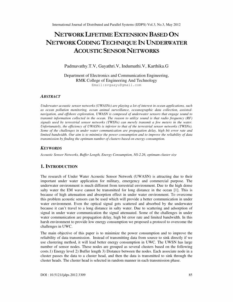
Figure 8. Random Deployment of Sensor nodes with Sink Node
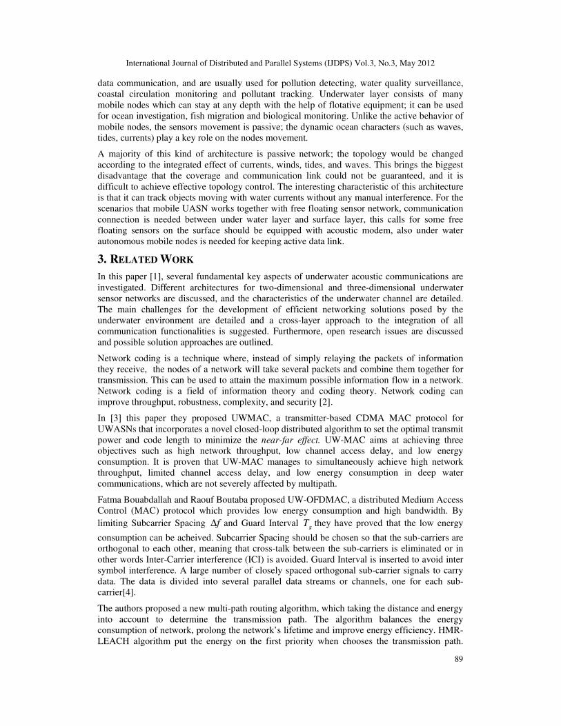
Figure 9. Cluster Head Selection based on energy Level
The Figure 9 shows example of the random sensor network with cluster head for different
round. In this figure 100 nodes are being deployed in the sensor network. In this proposed
algorithm provides sensor networks with many good features, such as clustering
architecture, localized coordination and randomized rotation of cluster-heads
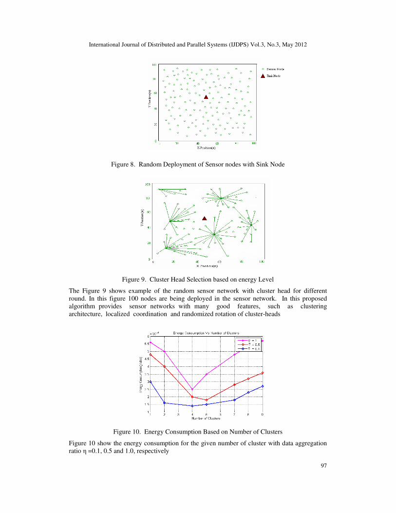
Figure 10. Energy Consumption Based on Number of Clusters
Figure 10 show the energy consumption for the given number of cluster with data aggregation
ratio η =0.1, 0.5 and 1.0, respectively

International Journal of Distributed and Parallel Systems (IJDPS) Vol.3, No.3, May 2012
98
Figure 11. Number of Alive Nodes based on Number of Rounds
Result in Figure 11 show the relationship between number of sensor nodes that remained alive
and the number of rounds. With EEHCA, EECDA LEACH, number of nodes almost died for
290,352 330 rounds respectively, but in proposed scheme, the number of nodes remain alive is
about 480. The simulation results illustrate the lifetime is prolonged increasingly by using the
proposed cluster head selection scheme.
8. CONCLUSION
In this paper we try to find optimal probability of a node to become a cluster head that leads to
minimize the overall energy consumption in the network for a more complex and general
scenario. A suitable analytical model is used to find the optimum number of clusters thereby
increasing the sleeping nodes, which in turn reduces the energy consumption of nodes. The
proposed protocol is compared with the existing protocol and the result is summarized. We
formulate the optimal way for determining number of CH for different scenario with the
objective of guaranteed connectivity and minimizing the total energy spent in the system. We
found that the optimal parameter values for these scenario and complex model will not only
depend on number of nodes that was considered by LEACH and M-LEACH protocol but also
depends on transmission range, packet length, circuit dissipation energy, buffer length etc.
9. REFERENCE
[1] Ian F. Akyildiz , Dario Pompili, Tommaso Melodia,“Underwater acoustic sensor networks:
research challenges”, International Journal on Ad Hoc Networks , Vol 3, pp 257–279, 2005.
[2] Tracey ho and Desmond S.Lun , Published in the United States of America by Cambridge
University Press, New York “Network Coding An Introduction”,2008.
[3] Dario Pompili, Tommaso Melodia and Ian F. Akyildiz , “A Distributed CDMA Medium Access
Control for Underwater Acoustic Sensor Networks”, Sixth Annual Mediterranean Ad Hoc
Networking WorkShop, Corfu, Greece, June 12-15, 2007.
[4] Fatma Bouabdallah and Raouf Boutaba, “ A Distributed OFDMA Medium Access Control for
Underwater Acoustic Sensors Networks” IEEE International Conference on Communications pp
1-5, ISBN: 978-1-61284-231-8, June 2011.
[5] Guangzhong Liu and Changye Wei, “A New Multi-path Routing Protocol Based on Cluster for
Underwater Acoustic Sensor Networks” IEEE National Natural Science Foundation pp 91-94,
ISBN: 978-1-61284-771-9, July 2011.

International Journal of Distributed and Parallel Systems (IJDPS) Vol.3, No.3, May 2012
99
[6] Guangsong Yang, Mingbo Xiao, En Cheng and Jing Zhang, “A Cluster-head Selection Scheme
for Underwater Acoustic Sensor Networks” IEEE International Conference on Communications
and Mobile Computing, pp 188-191, ISBN: 978-1-4244-6327-5, April 2010.
[7] Jinyong Cheon and Ho-Shin Cho, “A delay-tolerant OFDMA-based MAC Protocol for
Underwater Acoustic Sensor Networks” IEEE International Conference on Communications pp
1-4, ISBN: 978-1-4577-0165-8, April 2011.
[8] Long-Shin Chen, Zong-Yi Lyu and Zeng-Wen Hong, “An Efficient Cluster Head Selection
Strategy for Wireless Sensor network” IEEE Fifth conference on Genetic and Evolutionary
Computing pp 37-40, ISBN: 978-1-4577-0817-6, August 2011.
[9] Dang Nguyen, Pascale Minet, Thomas Kunz and Louise Lamont, “New Findings on the
Complexity of Cluster Head Selection Algorithms” IEEE International Symposium on World of
Wireless, Mobile and Multimedia Networks pp 1-10, ISBN: 978-1-4577-0352-2, June 2011.
[10] H. N. Egbo, N. J. Hallin, P. L. Ray, M. O’Rourke, J. F. Frenzel and D. B. Edwards, “Token-
Based Medium Access Control Solution for Underwater Acoustic Broadcast” IEEE Biloxi-
Marine Technology for our future goal: Global and Local Challenges pp1-9, ISBN: 978-1-4244-
4960-6, October 2009.
[11] Borja Peleato and Milica Stojanovic, “Distance Aware Collision Avoidance Protocol for Ad-
Hoc Underwater Acoustic Sensor Networks”, IEEE Communications Letters, Vol.11, Issue 12,
pp 1025 - 1027 ,ISBN: 1089-7798, December 2007.
[12] Zhang Yingying, Li Xia, Fang Shilia “Deployment analysis in two-dimensional Underwater
Acoustic Wireless Sensor Networks” IEEE International Conference on Signal Processing, pp1-
5, ISBN: 978-1-4577-0893-0, September 2011.
[13] Zhang Yingying, Li Xia, Fang Shiliang, “A research on the deployment of sensors in
Underwater Acoustic Wireless Sensor Networks” 2nd International Conference on Information
Science and Engineering (ICISE), pp4312-4315, ISBN: 978-1-4244-7616-9, December 2011.
[14] Wang Chen; Fang Yanjun; “Physical layer design consideration for Underwater Acoustic
Sensor Networks” 3rd IEEE International Conference on Computer Science and Information
Technology (ICCSIT) pp 606-609, ISBN: 978-1-4244-5537-9, July 2010.
[15] Yun Li, Nan Yu, Weiyi Zhang, Weiliang Zhao, Xiaohu You and Daneshmand, M “Enhancing
the performance of LEACH protocol in wireless sensor networks”, IEEE Conference on
Computer Communications Workshops (INFOCOMS WKSHPS), pp.223-228, ISBN: 978- 1-
4577-0249-5, April 2011.
[16] Heikalabad, S.R., Firouz, N., Navin, A.H and Mirnia, M.K, “HEECH: Hybrid Energy Effective
Clustering Hierarchical Protocol for Lifetime Prolonging in Wireless Sensor Networks”
International Conference on Computational Intelligence and Communication Networks (CICN),
pp.325-328, ISBN: 978-1-4244-8653-3, November 2010.
[17] Nitthita Chirdchoo, Mandar Chitre, Wee-Seng Soh , “A study on network coding in underwater
networks”,Published in IEEE Oceans, Seattle WA, pp1-8, September,2010.
Authors
T.V.Padmavathy obtained her A.M.I.E (ECE) from the Institution of Engineers (India),
M.C.A from University of Madras and M.E., degree from College of Engineering, Anna
University in the years 1996, 2001 and 2004 respectively. She has 13 years of teaching
experience. She is working as Assistant Professor in the Department of Electronics and
Communication Engineering, Chennai. She is presently a research scholar in Anna

International Journal of Distributed and Parallel Systems (IJDPS) Vol.3, No.3, May 2012
100
University. She has published over 19 research papers in National/International Journal and conference
proceedings. She is a member of IEEE, IETE and ISTE. Her area of interest is Wireless Sensor Networks
and Embedded Systems.
Gayathri.V, educated from Maharishi Vidya Madir upto class XII, played an important
role in all school activities, especially specializing in French, obtaining state rank and
received awards. She is good at volleyball and has represented her school in district level
tournaments. She has a passion to play veena. She got ECE branch in RMKCET on merit
and presently pursuing her final year with excellent performance throughout. She Won
“Best Paper Award” for two papers in national conferences held at Vel Tech Engineering
College and at Vel Srinivasa Engineering College. Her areas of interest are Wireless Sensor Networks
and RFID.
Indhumathi.V, currently doing her Bachelor of Engineering in Electronics and Communication
Engineering in R.M.K College of Engineering and Technology. She did her schooling in
Vellayan Chettiyar Higher Secondary School. She won proficiency award for the year2009-2011
and got Distinction in Mathematics in S.S.L.C. Her field of interest includes
wireless sensor networks and radio frequency engineering.
Karthika.G, currently doing her Bachelor of Engineering in Electronics and Communication
Engineering in R.M.K College of Engineering and Technology. She did her schooling in
Velammal Matriculation Higher Secondary School. Her field of interest includes
Networking and security.