NASA ENGINEERING AND SAFETY CENTER
37
www.nasa.gov NASA ENGINEERING AND SAFETY CENTER 15 YEARS OF ENGINEERING EXCELLENCE 2018 TECHNICAL UPDATE
-
Upload
khangminh22 -
Category
Documents
-
view
3 -
download
0
Transcript of NASA ENGINEERING AND SAFETY CENTER

www.nasa.gov
NASA ENGINEERING AND SAFETY CENTER
15 YEARS OF ENGINEERING EXCELLENCE
2 0 1 8 T E C H N I C A L U P D A T E

12018 NESC TECHNICAL UPDATE
From NASA Leadership
The NESC has provided an extensive number of independent technical assessments and program support over the past 15 years. While it is easy to look back and consider the effect this organization has had on NASA missions in the recent past, the NESC continues to look forward. We have much to do as an Agency as we prepare five major NASA programs, including our commercial partners, for quali-fication and flight, and the NESC is critical as an Agency resource to help enable these programs. Ensuring the safety of our astronauts is the most important thing we can do, and that focus is unwavering in the NESC. The dedication of the men and women in this organization is tremendous, and I am confident in our path forward as we progress toward the moon and Mars.”
Stephen JurczykNASA Associate Administrator
NASA is making significant progress in completing several major development programs that will propel the nation forward in space exploration. Programs like the Orion Multi-Purpose Crew Vehicle, the Space Launch System, the James Webb Space Telescope, and spacecraft under development with the Commercial Crew Program are well into their test and qualification phases, as they move closer to planned launch dates. The NESC, having just completed its 15th year as the Agency’s key technical resource, has played an integral part in the design and development activities for these programs, pro-viding expertise and solutions to the unique and critical engineering challenges we have faced as these programs have matured. NASA has its sights set on enabling long-term exploration and utilization of the moon and moving out to Mars, while it continues to push forward scientific endeavors to other planetary bodies to better understand the origins and evolution of the universe. We continue to rely on the NESC to ensure we do this with a full understanding of the risks that lay before us and secure in the knowledge that we have taken all the appropriate actions to ensure mission success.”
ENGINEERING EXCELLENCE
Ralph R. Roe, Jr.NASA Chief Engineer

2018 NESC TECHNICAL UPDATE 2018 NESC TECHNICAL UPDATE
CONTENTSTable of Contents
32018 NESC TECHNICAL UPDATE2
NESC OverviewThe organization performs value-added independent testing, analysis, and assessments of NASA'shigh-risk projects to ensure safety and mission success.
A Look BackReflecting on 15 Years in the NESCAfter 15 years and more than 850 assessments, the five remaining original members reflect on the NESC’s efforts to implement an operations model that would help return Shuttle to flight and addressthe complex issues that would come with a new era of spacecraft development.
NASA Technical FellowsNASA's Senior Technical ExpertsCornelius Dennehy, lead for the NASA Technical Fellows, discusses the role of and significant contributions made by these technical leaders.
Discipline FocusDiscipline Perspectives Related to NESC Assessments 14-15 Mars Dust: Understanding a Multifaceted Problem 16-17 Early Results from the S-FTRC 18-19 Advancing Model Based Systems Engineering 20-21 Application of Resilience Engineering to Risk Management in Sociotechnical Systems Like ISS 22-23 Avionics: Understand the Mission, Environment, Application, and Lifetime
NESC Knowledge ProductsCapturing and Preserving Critical Knowledge for the FutureThe NESC develops a wide variety of knowledge products that can be readily accessed includingtechnical assessment reports, technical bulletins, video libraries, and more.
4-7
8-11
12-13
14-23
24-25
26-41
53
42-52
56-61
62-63
64-65
66-68
69
Assessment and Support ActivitiesTechnical Assessments and Support Activities Conducted by the NESC in 2018
NESC at the CentersDrawing Upon Resources from the Entire AgencyMeet the engineers and scientists who come from across all NASA Centers to lend their expertiseto NESC assessments.
Lessons LearnedCaptured Knowledge from NESC AssessmentsNESC shares lessons learned during assessments that have broad-reaching relevance for NASA missions.
Workforce DevelopmentGaining Hands-on Experience through NESC Assessments The NESC reaps the benefits that young, intelligent, and enthusiastic minds can bring to assessments.
Innovative TechniquesSolutions Developed from NESC Assessments Deformed Geometry Coupling Technique for Determining Preload of a Stacked Launch Vehicle 58 Fast Attitude Maneuvers for Lunar Reconnaissance Orbiter 59 Heading Advisory Tool for Crew Module Recovery 60 NiTi-Hf Alloy for Corrosion Immune, Shockproof Bearings 61 COPV Test and Measurement Techniques
NESC Honor Awards
NESC Leadership and Alumni
PublicationsBased on NESC Activities
Acronyms
56-57
54-55
Gaining Hands-on Experiencethrough NESC Assessments
F/A-18 FleetPhysiological Events
Heading Advisory Tool forCrew Module Recovery
Deformed Geometry CouplingTechnique for Determining Preloadof a Stacked Launch Vehicle
Mars Dust: Understandinga Multifaceted Problem
Application of Resilience Engineering to Risk Management in Sociotechnical Systems Like ISS
ENGINEERING EXCELLENCE
14-15 54-5527 5920-21 56-57

2018 NESC TECHNICAL UPDATE
The NASA Engineering and Safety Center (NESC) was created fifteen years ago as an organization dedicated to en-suring safety – achieved by directing outstanding engineering expertise to the toughest technical problems. Having ready access to that expertise from outside the program or Cen-ter that needs it, even outside of NASA itself, is one of the unique features that defines the NESC. This NESC Technical Update highlights the preceding year’s accomplishments and looks back on some of the milestones that took place over the past fifteen years. This year’s edition looks back to the NESC’s early years by presenting perspectives from current NESC employees who were with the organization from the start (page 8). Subsequent sections provide insight into how the various components of the NESC function and introduces some of the products produced by NESC activities. One of the essential elements of the NESC is the NASA Technical Fellows office (page 12). The Technical Fellows are NASA’s senior technical experts – stewards of their engineer-ing disciplines and leaders of their Technical Discipline Teams (TDTs). The Discipline Focus features beginning on page 14 present perspectives from 5 of the 21 TDT disciplines. The
TDTs serve as pools of talent that are drawn from NASA, aca-demia, industry, and other government agencies. Members of these TDTs provide the technical expertise needed for NESC assessments: focused teams that are formed quickly to at-tack specific issues. Many of the assessments, especially those that are complex or involve multiple disciplines, are led by members of the Principal Engineers Office. Assessments and other support activities that were completed this year are summarized beginning on page 26. The NESC is distributed throughout the Agency with a strong presence at each of the ten NASA Centers. NESC Chief Engineers (NCEs) at each one provide insight into their respective Center’s activities. They also help coordinate Cen-ter personnel and resources required to support NESC as-sessments. NESC at the Centers (pages 42-52) details how each Center has contributed to the NESC this year, focusing on some of the many individuals who contributed to NESC assessments. But supporting the NESC also benefits the as-sessment team members by imparting problem-solving expe-rience and making valuable technical contacts from across the Agency – tools they take back to their home organizations.
The Workforce Development feature on pages 54-55 shows examples of how this interaction is helping the Agency devel-op its engineers. The NESC could not function without two additional of-fices: the Management and Technical Support Office (MTSO) and the NESC Integration Office (NIO). The MTSO performs the procurement and contracting activities needed for each assessment. The NIO provides technical integration for the NESC’s internal operations, including processing all requests for NESC support, and provides integration and system engi-neering support to assessments. Finally, the Office of the Di-rector provides overall guidance and leadership for the NESC. Members of these six NESC offices all come together to discuss and approve NESC products at the NESC Review Board (NRB). The NRB is a critical element of the NESC be-cause the diversity in experience and technical backgrounds results in different lenses through which to view problems. This produces well-rounded and robust solutions that the NESC shares through its knowledge products like final re-ports, technical publications, and lessons learned featured at the end of the publication. This year’s Technical Update also introduces the 2018 NESC Honor Award recipients (pages 62-63) and discusses some of the innovative tech-niques spawned by NESC activities (pages 56-61). The NESC will continue to evolve to address NASA’s priorities. The NESC of the future may focus on different missions and programs than today, but the objective will always be to ensure safety and mission success through engineering excellence.
MEMBERS OF THE NESC
November 2018
NESC OVERVIEW
54 2018 NESC TECHNICAL UPDATE
NESCOVERVIEW
Per forming Value-addedIndependent Test ing, Analys is ,and Assessments
NASA72%
Industry22%
Academia2%
Other Gov.4%
NASA Engineering & Safety Center Core Team
Technical Discipline Teams (TDT)
More Than 900 TDT Members
AerosciencesAvionicsCryogenicsElectrical PowerEnvironmentalControl/Life SupportFlight MechanicsGuidance, Navigation, and Control
PropulsionRobotic SpaceflightSensors/InstrumentationSoftwareSpace EnvironmentsStructuresSystems Engineering
Human FactorsLoads and DynamicsMaterialsMechanical SystemsNondestructiveEvaluationNuclear Power and PropulsionPassive Thermal
TECH
NIC
AL LEADER
SHIP
AND
MAN
AGEM
ENT
TECH
NIC
AL WO
RKFO
RC
E
Approval Peer Review and Approval
RequestSubmitted(by anyone)
RequestProcessed,
Evaluated, andAccepted
AssessmentTeam Formed
andPlan Developedand Approved
NESC Review Board NESC Review Board
Deliver FinalReport to
Stakeholders
SubmittedRequests Evaluated
Based onNESC Selection
Prioritiesand OCE Risks
NESC Core and Extended Team
Members
DocumentFindings,
Observations,and
Recommendations
Proceed with Assessment
(Testing, Data Collection, Modeling, and Analysis)
THE PROCESS:PERFORMING NESC ASSESSMENTS
NASA TechnicalFellows
PENESC
PrincipalEngineers
MTSOManagementand TechnicalSupport Office
NIONESC
IntegrationOffice
Office ofthe Director
NCENESCChief
Engineers
NRBNESC Review Board
Assessment Team
NASA Office of the Chief Engineer

Accepted Requests Since 2003:858 tota l , 90 in FY18
An Agency-wide resource that provides a forum for reporting technical issues and contributing alternative viewpoints to resolve NASA’s highest-risk challenges. Multidisciplinary teams of ready experts provide distinctively unbiased technical assessments to enable more informed decisions.
The NESC performs technical assessments and provides recommendations based on independent testing and analysis rather than subjective opinion. An independent reporting path and independent funding from the Office of the Chief Engineer help ensure objective technical results for NASA.
The NESC draws on the knowledge base of technical experts from across NASA, industry, academia, and other government agencies. Collaborating with leading engineers allows the NESC to consistently optimize processes, strengthen technical capabilities, and broaden perspectives. This practice further reinforces the NESC’s commitment to engineering excellence.
A Unique Resource
Independenceand Object iv i ty
Engineer ing Exce l lence
ENGINEERING EXCELLENCE
NASA ENGINEERINGAND SAFETY CENTER
DATA AS OF SEPTEMBER 30, 2018
7
For general information and requests for technical assistance visit: nesc.nasa.govFor anonymous requests write to: NESC, NASA Langley Research Center, Mail Stop 118, Hampton, VA 23681-2199
6
NESC OVERVIEWNESC OVERVIEW
Artist Cece Bibby painting Sigma Seven logo on Mercury spacecraft with Astronaut Wally Schirra, 1962
The NESC Ins ignia Or ig in “I named my spacecraft Sigma Seven. Sigma, a Greek symbol for the sum of the elements of an equation, stands for engineering excellence. That was my goal - engineering excellence.” - Wally Schirra For the NESC, the Sigma also represents engineering excellence. The NESC’s unique insignia has its roots in the early Mercury program. While the Sigma Seven represented the seven Mercury astronauts, the "10" in the NESC insignia represents the ten NASA Centers. The NESC draws upon resources from the entire Agency to ensure engineering excellence.
130 IN-PROGRESS REQUESTSBY PRIORITY
PRIORITY
1
PRIORITY
3
PRIORITY
5
PRIORITY 1Projects in the flight phase
PRIORITY 3Known problemsnot being addressed by any project
PRIORITY 5Work to improvea system
PRIORITY 2Projects in the design phase
PRIORITY 4Work to avoid
potential future problems
10%12%
10%
PRIORITY
210%62%
PRIORITY
45%
12%
9%
ACCEPTED REQUESTSBY MISSION DIRECTORATE
FY14-FY18
Human Exploration and Operations (Operations)
50%
Broad Agency/External 15%
SpaceTechnology
4% Human Explorationand Operations
(Exploration)
13%
AeronauticsResearch
2%
Science 16%
SOURCES OF ACCEPTED REQUESTS SINCE 2003
Center Management
Office of Safety and Mission Assurance
Office of Chief Engineer
Safety and Mission Assurance at Centers
Other NASA Offices
Program Management
NESC
2%2%
3%3%
17%20%
External to Agency 3%3%
Anonymous 1%
Engineering and Scientific Organizations
46%
IN-PROGRESS REQUESTSTHROUGH FY18 BY EFFECTIVITY
5 10 15 20 25 30
Broad Agency 23
CCP 25
MPCV 17
SLS 12
ESD 10
ISS 7
General 5
EGS 4
STMD 2
External 2
ARMD 2
LSP 1
SMD 20
2018 NESC TECHNICAL UPDATE 2018 NESC TECHNICAL UPDATE

to the Columbia failure,” he said, “and I hoped my participation might help ensure such a thing would not happen again.” Working to Establish Credibility During the first four years, a little more than 50% of NESC assessments focused on the Shuttle Program and the International Space Station (ISS). They ranged from analyzing recurring Shuttle flight anomalies and evaluating hail strike damage on external tank foam to investigating reduced adherence between the protective coating on the orbiter wing’s leading edge and the underlying substrate. “It was high visibility and high profile work, and the an-swer was not obvious,” said Mr. Wilson of the adherence issue, which carried implications for the Shuttle and the safety of its crew, especially after Columbia. “It took a tremendous amount of work and a dedicated team to plow through all of the data and make sense of it.” The assessment led to improved non-destructive evaluation (NDE) inspection methods and is oneMr. Wilson felt made significant contributions to the program. Those early assessments were challenging for more than just their technical complexity. Staffing assessment teams “meant prying resources away from other programs and Cen-ters to be a part of our team,” he said. “That was a hard sell.” Programs weren’t fond of the idea of sending their top talent to work at a new organization, even though the positions were meant to be temporary, no more than 5 years. And once as-sembled, a team of recognized senior discipline experts did not necessarily lend the NESC credibility overnight. “Programs didn’t really know what we were about and weren’t quick to trust us because we didn’t have a track record.” That was especially true with the Shuttle Program. “The perception was that you couldn’t bring in someone from out-side the program and engage them in a problem – that there just wasn’t time to come up to speed and understand all of the subtleties of Shuttle systems. Fortunately, when we brought in our then discipline expert for power and avionics and plugged him into a major Shuttle issue, he was able to very quickly give them useful, value-added answers.” That went a long way to gaining the confidence of the Shuttle Program, he said. In tandem, the NESC was working out its internal logis-tics. Bringing together a NASA-wide group of engineers for
the NESC was a lesson learned in cross-culturalism, saidDr. Michael Gilbert, who started as the NESC Chief Engineer for LaRC and is now a Principal Engineer. “We were learning quite a bit in those days about who we were and how we were going to operate.” During an assessment to address failure risks with Shuttle’s primary reaction jet drivers, engineers from both human and robotic spaceflight intensely debated the is-sues. “That’s when many of us realized that significant cultural differences existed between the human and robotic sides of NASA engineering.” There was a learning curve to climb as everyone worked to understand each other’s engineering ap-proach and how they characterized the risks involved.
As the NESC took on more assessments, there were oc-casions when NESC positions were contrary to a program’s position on launch readiness or could impact cost or sched-ule. Though uncommon, it showed the NESC model, with its independent reporting path to NASA’s highest technical lead-ership, was working. NESC positions could be elevated to the Office of the Chief Engineer and ultimately, the NASA Admin-istrator. “When you read the Columbia or Challenger accident reports, you find that upper level managers who were making the final launch decisions were unaware of technical discon-nects down the line,” said Dr. Gilbert. For him, these instances made the NESC contribution to the Agency crystal clear. “It’s
In response to the Columbia accident in 2003, then NASA Administrator Mr. Sean O’Keefe established the NESC. Its first Director, Mr. Ralph Roe, with support from the Chief Safety and Mission Assurance Officer and former astronautMr. Bryan O’Connor, organized the NESC with a specific mis-sion: provide independent assessments of NASA’s toughest technical issues while striving for a culture of engineering excellence. After 15 years and more than 850 assessments, the five remaining original members reflected on the NESC’sefforts to implement an operations model that would help re-turn the Shuttle to flight and address the complex issues that would come with a new era of spacecraft development. Testing the NESC Model In November 2003, the newly-formed NESC assembled its first assessment team to address concerns with the pro-pulsion bus design for the CALIPSO spacecraft scheduled to launch in early 2006. The satellite’s propulsion bus had been manufactured using mechanical fittings to contain highly tox-ic propulsion fluids rather than the welded systems typically used by NASA. The NESC was asked to review the bus design and assess the risk of propellant leakage. “Our approach was to lay out a fault tree that showed everything that could possibly go wrong and determine if the appropriate controls were in place during the build process to ensure those fittings wouldn’t leak,” said NESC DirectorMr. Tim Wilson. The assessment provided the data NASA and the CALIPSO Program needed to determine the mission’s
safety for flight. It also served as the first test run of the NESC operations model – an institutionalized tiger team approach where quickly assembled teams from a ready pool of NASA technical experts are set to task on a problem.
“We put our team together, laid out the problem, and tackled it,” said Mr. Wilson, who at that time had just transi-tioned from more than 15 years with the Shuttle Program to become the NESC’s first Chief Engineer at KSC. When of-fered the NESC position, Mr. Wilson felt it was an opportunity to do something different and challenging, and in the wake ofColumbia, a way to move forward. “It was a positive response
A Look Back
98
A LOOK BACK: Ref lect ing on 15 Years in the NESC A LOOK BACK: Ref lect ing on 15 Years in the NESC
We target issuesthat have the most payback for the Agency as a whole and crosscut multiple programs, and we try to ensure our work lines up with the NASA Chief Engineer’s priorities.”
Timmy R. WilsonNESC Director
It’s not that theNESC has the final say. It’s that we make sure the decisions that are madeare fully risk-informed.”
Dr. Michael G. GilbertNESC Principal Engineer
Ref lect ingon 15 Years in
the NESC
FEATURING NESC MEMBERS:T immy Wilson, Michael G i lber t , C l in ton Cragg, Cynthia Nul l , and Henr y Rot ter
F-22 Life SupportSystem Independent
AnalysisEMU Lithium-ion
Battery AssessmentReview of SLSFlight Software
Proof Factorsfor COPVs
Human Systems Integration for Safety-
Critical Range Ops
2003
October 2005100th Technical
Assessment Initiated
June 2007200th Technical
Assessment Initiated
September 2009300th Technical
Assessment Initiated
February 2011400th Technical
Assessment Initiated
July 2016700th Technical
Assessment Initiated
February 2018800th Technical
Assessment Initiated
January 2013500th Technical
Assessment Initiated
October 2014600th Technical
Assessment Initiated
03 05 07 09 11 13 15 17
04 06 08 10 12 14 16 18
November 20031st Technical
Assessment Initiated
2018
CALIPSO Proteus Propulsion Bus
Design Concerns
Recovery Plan for EMU& ISS Airlock Coolant Loop Review for RTF
Alternate LaunchAbort System
Shell Buckling Knockdown Factor
ProposalCOPV Life PredictionModel Development
NASA Supportto Trapped Chilean
Miners
NESCEstablished
Orbiter Flowliner Test Planning and Flight Rationale
Composite CrewModule Pressure
VesselKepler Reaction
Wheel Usage PlanMax Launch
Abort SystemPyrovalve ReliabilityAssessment for ELV
Payloads
Independent Modeling & Simulation
for CCP EDLEEE Parts Testing
for CCPF/A-18 Fleet
Physiological Events
NOTEWORTHY ASSESSMENTS
MPCV Avcoat Study

November 2003CALIPSO Proteus PropulsionBus Design ConcernsPrior to launch of NASA’s CALIPSO satellite, the hydrazine-fueled propulsion bus design was reviewed to assess the risk for propellant leakage and recommend measures to mitigate potential personnel exposure hazards during system fill and pressurization.
January 2004Orbiter Flowliner TestPlanning and Flight RationaleFollowing repair of cracks in orbiter engine gimbal joint flowliners, a strategy for post-repair flight rationale was developed using fatigue loading spectra, a high fidelity inspection method, and refined three-dimensional fracture mechanics analysis methods.
April 2004Orbiter Reaction JetDrivers Potential ShortElectrical testing and physical analysis of orbiter reaction jet drivers, which control thrusters for vehicle maneuvering, were performed to assess failure modes and screen for potential aging and degradation effects on transistors and wiring.
October2003Ralph Roe, Jr.serves as thefirst NESC Director.
July 2003The NESC is EstablishedShortly following the Columbia accident, NASA Administrator Sean O’Keefe announced plans to create the NESC to serve as an Agency-wide technical resource focused on engineering excellence to proactively help NASA avoid future problems.
1S T A S S E S S M E N T
1110
not that the NESC has the final say. It’s that we make sure the decisions that are made are fully risk-informed.” Continuing the Mission After Shuttle When the Space Shuttle retired in 2011, the NESC was already engaged in assessments for the newly-formed Commercial Crew Program (CCP), which was working with companies such as Boeing, SpaceX, and Sierra Nevada on the development of vehicles to transport cargo and crew to the ISS (see graph, p. 11). The NESC also undertook initiatives that would ultimately benefit NASA’s newest exploration spacecraft, Orion Multi-Purpose Crew Vehicle (MPCV), such as designing and building a composite crew module to gain knowledge in composite construction and evaluating alternate launch abort system designs. The NESC also led efforts to update Apollo-era shell buckling knockdown factors, used today by the Space Launch System (SLS) to lighten the launch vehicle and reduce material costs. Relationships built during Shuttle and ISS assessments had laid a foundation of trust. Former NESC members were also fostering credibility. “There have been a number of people who came to the NESC and then moved on to other positions at NASA,” said Mr. Clinton Cragg, an NESC Principal Engineer. “They knew our capabilities and would come to us because they knew we could help.” A retired U.S. Navy submarine commander, Mr. Cragg’s first NESC assessment was to provide flight rationale following
the repair of cracks found in the Shuttle’s main engine gim-bal joint flow liners. New to the NESC and NASA, he worked with a veteran NASA engineer to help him “learn the ropes.” He has led many NESC assessments since, including several for stakeholders outside of NASA, such as the Air Force and Navy in support of issues with their fighter aircraft fleets and the country of Chile with their rescue of 33 trapped miners. “I can get the relevant expertise, whether from NASA, in-dustry, or academia, and put together a highly-qualified team in no time at all. That’s a big strength of the NESC. And be-cause the teams are small and concise, you can change on a dime the direction you want to take with an assessment so you can get to the truth quicker.” Since her start at the NESC, Dr. Cynthia Null’s NESC assessment work has involved the interaction of humans with aircraft systems, full-scale engine test stands, flight-test range systems, spacecraft systems, and spacecraft ground systems. As the NASA Technical Fellow for Human Factors, Dr. Null has watched those systems become more complex and challeng-ing for operators. “The hardest engineering problems are at interfaces: between subsystems and between operations, environments, software, and people. Working challenging technical problems with a systems engineering approach enables NESC multi-discipline teams to increase technical understanding, identify risk, and provide alternative approaches,” she said. “I have learned a great deal from my NESC colleagues and the larger
community of scientists and engineers who provide critical expertise to our work. I am grateful that I’ve been able to lend a hand.”Adapting the NESC Model to NASA’s Evolving Mission While its operating model has changed very little over the years, the NESC has adjusted its composition periodically to stay aligned with the Agency’s programs. Previously joined disciplines such as Electrical Power and Avionics were sep-arated to address the amount and scope of work coming in and additional disciplines were added to cover emerging work areas such as cryogenics, space environments, and systems engineering. “We target issues that have the most payback for the Agency as a whole and crosscut multiple programs,” said Mr. Wilson. “And we try to ensure our work lines up with the NASA Chief Engineer’s priorities.” NESC expertise has also evolved to support new space-craft and emerging technology. Mr. Hank Rotter, the NASA Technical Fellow for Environmental Control and Life Support (ECLS), was already a NASA veteran when he joined the NESC, bringing ECLS experience amassed since 1963. His early assessments addressed issues such as coolant pump failures on the ISS Extravehicular Mobility Unit. But over the past 15 years, his work has included assessments for the ISS, Mars Science Lab Rover, Solar Probe Plus, Europa Clipper, Orion, and for life support systems on the Air Force F-22 and Navy F/A-18 aircraft. The opportunities to apply his skills and
continue learning have kept him at the NESC. “I stayed be-cause of these challenges,” said Mr. Rotter, “and because the types of assessments we work make a difference.” Where Mr. Wilson feels the NESC has most evolved is in how it connects with its stakeholders. “The way we engage is more collaborative than before. We’ve learned that it helps us give them better solutions.” By design, the NESC is indepen-dent of programs and projects so it can maintain objectivity, but keeping the programs and projects involved offers them ownership in the process. “This improves communication and makes it more likely they will act on our recommendations,”Mr. Wilson said. As new human spaceflight projects come online, the NESC will again work real time problems as it did with Shuttle. “We have to continue to focus on the right things and deliver high-value products and not become complacent in the work we do. Staying vigilant, doing good work, and communicating our results is important,” said Mr. Wilson. “I will not tell you that we are perfect, but I think we add value where we engage, and we’ve built a reputation for being able to help.”
A LOOK BACK: Ref lect ing on 15 Years in the NESC
700
200
300
400
500
600
100
ACCEPTED REQUESTS FOR SPACE SHUTTLEPROGRAM vs. ALL ACCEPTED REQUESTS
2004 2006 2008 2010 2012 2014 2016 2018
Space Shuttle Program All Other Total
A LOOK BACK: Ref lect ing on 15 Years in the NESC
I can get therelevant expertise, whether from NASA, industry, or academia, and put together a highly-qualified team in no time at all. That is a big strength of the NESC.”
Clinton H. CraggNESC Principal Engineer
I have learned agreat deal from my NESC colleagues and the larger community of scientists and engineers that provide critical expertise to our work."
Dr. Cynthia H. NullNASA Technical Fellowfor Human Factors
I stayed…because the types of assessments we work make a difference.”
Henry A. RotterNASA Technical Fellowfor Environmental Control and Life Support
Num
ber o
f Req
uest
s
15 Years o f Eng ineer ing Exce l lenceNESC HIGHLIGHTS

• Senior-level engineers and scientists with distinguished and sustained records of technical achievement
• Agency’s leading experts in their respective technical disciplines
• Lead/participate in NESC assessments
• Maintain NESC Technical Discipline Teams with ready-experts
• Promote discipline stewardship through workshops, conferences, and assorted discipline-advancing activities
• Provide technical consistency across NASA through inputs to Agency-level specifications and standards and the tailoring of those standards for programs and projects
• Provide leadership and act as role models for NASA discipline engineering communities beyond the TDTs
• Ensure lessons learned are identified, widely shared across engineering organizations, and incorporated into Agency processes
• Serve as NASA Capability Leaders, assessing technical discipline readiness to execute current and future missions; conduct discipline specific gap analyses to identify areas that require strategic investment to develop fundamental engineering sciences; and provide recommendations to promote capability health
August 2004Cassini/Huygens Entry,Descent, and LandingEDL analysis for the Saturn exploration probe included a focus on parachute deployment trigger performance, prediction of the aerodynamic and radiative heating environment encountered at Titan, and the corresponding thermal protection system response.
August 2004SRB Hold-down PostStud Hang-upStuds holding the Space Shuttle in place on the mobile launch platform would not retract, increasing liftoff loads. Extensive hardware tests paired with modeling and simulation helped determine root cause and mitigation options.
September 2004SOFIA AcousticalResonanceA review of technical reports and an independent parametric study helped resolve concerns about the acoustic environment within the telescope cavity of the SOFIA airborne observatory and the potential for structural damage from resonance or tones.
January 2006CEV Smart BuyerSupportThe Crew Exploration Vehicle Smart Buyer design was a multi-Center in-house effort to formulate an innovative CEV design. Seven key trade studies including propulsion, launch abort systems, and reusability helped generate driving requirements and alternatives.
March 2006Composite Crew ModulePressure VesselA composite structural test article wasdesigned, built, and tested with help from a network of engineers within the Agency with hands-on experience using composites on habitable spacecraft design.
May 2006CEV LAS AeroEvaluationComputational fluid dynamics analyses and wind tunnel testing examined the aerodynamic and shape sensitivities of a launch abort tower (tractor) versus a set of side mounted launch abort motors (pusher) on the service module.
The NESC has become widely recognized as a strong technical resource for customers and stakeholders seeking responsive service for solving NASA’s most difficult technical problems. NESC’s core technical strength is rooted in the broad knowledge base provided by the NASA Technical Fellows and their TDTs. When an Agency program or project requests help in tackling a challenging technical problem, the NESC typically turns to the NASA Technical Fellows to provide their expertise to solve it. Technical Fellows and their TDT members, drawn from across the Agency, have led or consulted on nearly all of the NESC’s technical assessments and can quickly be pulled together into specialized teams with just the right skill mix for the job. “It’s a bit of an art to assemble a team,” said Mr. Neil Dennehy, the NASA Technical Fellow for Guidance, Naviga-tion, and Control (GNC), who has led more than 25 NESC as-sessments. Each team reaches across Center boundaries, combining experts from multiple NASA disciplines as well as government and academia consultants. The art, he said, is in establishing the right balance of capabilities and knowledge to attack a problem from all sides, while maintaining an inde-pendent eye that is free from program or project bias. “With the right team doing independent tests and analyses, we can put data on the table to help our stakeholders understand their risk and mitigate it, or make the hard decisions like whether to add or eliminate testing.” Mr. Dennehy is one of 19 NASA Technical Fellows leading TDTs in their respective fields like Software, GNC, Aerosciences, or Space Environments. Started in 2007, the NASA Technical Fellow program has its roots in the former NESC Discipline Expert Group. As an Agency resource, they not only perform assessments, but also work to advance their disciplines and share knowledge and lessons learned via NESC Academy webcasts, technical reports, and workshops. “It’s a little overwhelming when you first step into the role of
Technical Fellow,” said Mr. Dennehy, who resides at GSFC. “You are asked to be the steward for your discipline, to alter your perspective, and raise your sights a little higher. We all had to take off our Center hats to adopt an overarching view of the Agency and what it needs.” The Technical Fellow role broadened significantly in recent years when NASA asked them to assemble Capability Leadership Teams (CLT). “As capability leaders, we look at the whole infrastructure of our disciplines – workforce, training, technology, and facilities – to ensure we can support the Agency now and in the future. We’ve all had to learn exactly how and where our workforce and tools are deployed in an effort to increase efficiency.”
Mr. Dennehy stays busy, as do the rest of the Technical Fellows. “We’re working for the NESC, leading TDTs and CLTs, and doing all of those things on the Technical Fellow checklist (see sidebar). The Agency has an unprecedented amount of work right now, especially in human spaceflight, so the pressure is on. We can’t have any technical misses so we double and triple check everything.” With every NASA mission the stakes are high, he said, and the safety and success of the mission are on the line. “We can’t afford to provide a wrong answer.” Mr. Dennehy said he’s amazed at what the NESC, Technical Fellows, and TDTs have accomplished. “When we
1312
The Role of aNASA Technica lFe l low
NASA TECHNICAL FELLOWS: NASA’s Senior Technica l Experts
NASA Technical FellowsNASA’s SeniorTechnica l Experts
Cornelius DennehyNASA Technical Fellow for GNC
go attack these problems, the assessment teams display so much passion for what they are doing. This often brings about a healthy tension as they debate ideas and narrow in on a solution.” But it’s a key part of the process, he added. “If everyone agreed at first, I’d have to wonder if we were fully attacking the problem.” With each assessment, Mr. Dennehy said the goal of the Technical Fellows is to provide timely and objective technical positions to their stakeholders that are based on independent test and analysis, not opinion. He credits successful assessments to the spirited and brilliant minds at NASA and the operational model the NESC developed early on for problem solving. “That model of having Technical Fellows build, maintain, and pull expertise and knowledge from the Centers to build their TDTs and assessment teams has worked better than I ever thought it could, and it is absolutely at the core of our success as a technical organization.”
The following article is based on an interview with Cornelius Dennehy, lead
for the NASA Technical Fellows.
That model of having Technical Fellows build, maintain, and pull expertise and knowledge from the Centers to build their TDTs and assessment teams has worked better than I ever thought it could, and it is absolutely at the core of our success as a technical organization.”
15 Years o f Eng ineer ing Exce l lence15 Years o f Eng ineer ing Exce l lence
Left to Right: (Front Row) Dr. Upendra N. Singh (Sensors/Instrumentation); Dr. Joseph I. Minow (Space Environments); Dr. Cynthia H. Null (Human Factors); Kauser Imtiaz (Structures); Richard W. Russell (Materials); Timmy Wilson (NESC Director); (Second Row) Daniel G. Murri (Flight Mechanics); Dwayne Morgan (Deputy for Avionics); Henry A. Rotter (Environmental Control/Life Support); Dr. Michael J. Dube (Mechanical Systems); Dr. David M. Schuster (Aerosciences); Dr. Dexter Johnson (Loads & Dynamics); (Third Row) Michael L. Meyer (Cryogenics); Cornelius J. Dennehy (Guidance, Navigation, & Control); Steven L. Rickman (Passive Thermal); Michael L. Aguilar (Software); Dr. Christopher J. Iannello (Electrical Power); Barry E. Wilmore (NESC Chief Astronaut); (Fourth Row) Jon B. Holladay (Systems Engineering); Michael Kirsch (NESC Deputy Director); | Not pictured: Dr. William H. Prosser (Nondestructive Evaluation); Dr. Daniel J. Dorney (Propulsion, not pictured); Dr. Robert F. Hodson (Avionics, not pictured)
NASA TECHNICAL FELLOWS: NASA’s Senior Technica l Experts

March 2007Shell Buckling KnockdownFactor ProposalDiscipline experts developed new analysis and test-based shell buckling knockdown factors for high-performance aerospace shell structures to enable significant weight savings for programs such as the Space Launch System.
May 2007Orbiter Wing Leading EdgeRCC Panel AnomalyInstances of reduced adherence between the protective coating on the orbiter wing’s leading edge and the underlying substrate led to investigations into root cause and the development of improved nondestructive evaluation methods for inspection.
June 2007Launch Abort SystemRisk Mitigation (MLAS)An alternate concept Launch Abort System was designed, developed, and demonstrated with a full-scale pad abort test as a risk mitigation for the Orion Project and to provide a fallback design for the Constellation Program.
November 2007CM Crew Seat LoadAttenuation and IsolationAlternate seat attenuation designs were devel-oped to improve landing survivability for Orion crew. Injury risk was reduced with better harness-ing techniques, which improved lateral restraint and offered a tight hold in a conformal seat.
February 2008Kepler Reaction WheelUsage PlanReaction wheel assembly failures on spacecraft prompted an assessment of mission risk for RWAs planned for the Kepler space observatory. Experts evaluated design, life requirements, and wheel usage and reviewed strategies to maximize RWA life.
October 2008Capsule Parachute AssemblySystem Reliability AnalysisBecause the CPAS is the top contributor to loss of crew probability for Orion, recommendations were provided on design options, development, testing, and verification planning to help develop a robust and reliable parachute design.
1514
Addressing Dust Impact on Human HealthThere is insufficient information on the toxicological featuresof Mars dust to set standards for duration of crew exposure.Future Mars missions should include instrumentation to obtain missingtoxicologically relevant in-situ measurements, and any Mars samplereturn materials should be examined to provide this information.
Addressing Dust Structure, Composition, and ChemistryThere is insufficient knowledge on the possibility of extant life on Mars. It is especially important to know if there are microbes present in the globally circulating dust for the purposes of planetary protection for a returned human mission. The question of life in the atmospheric dust can and should be addressed via Mars Sample Return. Because the atmospheric dust is globally mixed, the return and analysis of a single dust sample would be sufficient for this purpose.
Addressing Dust Impact to SystemsThere is insufficient knowledge of the dust particle size and frequency distribution in the lower atmosphere and on the surface. Knowledge of particle size would determine if particles will enter the astronauts' environments (suit, habitat, etc.) in significant quantity. Measurements should be conducted on the Martian surface for an extended period (multiple seasons), possibly with a filtration system designed to capture the particles from the ambient air, in conjunction with a measurement technique to determine the desired dust characteristics.
PHOTO: A Martian dust devil roughly 12 miles high was captured winding its way along the Amazonis Planitia region of Northern Mars on March 14, 2012, by the High Resolution Imaging Science Experiment camera on NASA's Mars Reconnaissance Orbiter.
Significant Workshop Results:
DISCIPLINE FOCUS: Robot ic Spacef l ight
DISCIPLINEFOCUS
Disc ip l ine Perspect ivesRelated to NESC Assessments
15 Years o f Eng ineer ing Exce l lence15 Years o f Eng ineer ing Exce l lence
MARS DUST: regolith particulates light enough to be lifted into the atmosphere by naturally occurring processes such as weather, electrostatic
mechanisms, or saltation, as well as by anticipated human activities
While the workshop produced dozens of detailed findings, observations, and recommendations related to the three questions and two long poles, the highest priority findings and recommendations in each of the three areas were:
Mars Dust: Understanding a Mul t i faceted Problem With the increasing focus on a crewed mission to Mars, many Mars-specific environmental factors are now being considered by NASA and other engineering teams. Learn-ing from NASA’s Apollo Missions, where lunar dust turned out to be a significant challenge to mission and crew safe-ty, attention is now turning to the dust in Mars’ atmosphere and regolith. Mars dust poses a multifaceted problem, raising concerns about human health, impact on surface systems (e.g., spacesuits, habitats, mobility systems), and on crewed surface operations. Even though four NASA rovers have tra-versed Mars’ landscape successfully for years now, landers have made measurements of their landing environments, and orbiters provided excellent data on planetary and synoptic/mesoscales, detailed knowledge of the dust’s characteristics and how it might affect mechanical, electrical, and human systems is still sparse.Defining Dust-Caused Challenges To start the process of identifying possible dust-caused challenges to human presence on Mars and thus aid early engineering and mission design efforts, the NESC Robotic Spacecraft TDT conducted a workshop on the “Dust in the Atmosphere of Mars and its Impact on Human Exploration” in June 2017. Participants included Mars scientists and en-gineers, mission architects, mission planners, and medical researchers including physicians and toxicologists.
The workshop participants formulated then addressed the fol-lowing general questions:• What is known about Mars dust in terms of its
physical and chemical properties, its local and global abundance and composition, and its variability?
• What is the impact of Mars atmospheric dust on human health?
• What is the impact of Mars atmospheric dust on surface mechanical systems?
The participants identified current knowledge and gapsin the three areas and suggested measurements and ex-periments needed to fill in the knowledge gaps prior to the first human landing on Mars. In an earlier independent effort,NASA’s Human Exploration and Operations Mission Director-ate identified several engineering long poles for getting hu-mans to the surface of Mars. A long pole is an engineering or capability challenge that has a major bearing on any mission and if left unresolved, could significantly delay or have a se-rious adverse impact on a particular mission. Two dust-relat-ed long pole topics at the workshop included evaluating the hazard potential of Mars regolith and atmospheric dust on crew health and Mars surface operations and surface dust filtration. They asserted that biological, toxicological, and me-chanical properties of the Martian regolith and atmospheric dust environment need to be characterized to evaluate their potential in impacting crew health, system reliability, and for-ward and backward planetary protection policies. Areas for Future Study Living on the Martian surface requires the development of capable habitation systems that must keep crew members healthy and productive for the duration of the surface missions. Keeping the dust below permissible limits (currently being de-termined) within the surface habitats will drive habitat design decisions. Measurements and experiments need to be taken and conducted on the surface of Mars by precursor landers to determine dust characteristics that will influence hardware design as well as provide toxicology data to safeguard crew health. In addition, dust samples need to be collected and ex-amined for possible extant life, perhaps via the Mars Sample Return mission. Recent findings by the Curiosity Rover Team regarding the presence of complex organics and seasonal methane are important steps in this direction. This workshop was a starting point for problem identification activities that will continue for years, with future workshops providing in-creasingly focused advice usable for engineering solutions.
Dr. Daniel WinterhalterNESC Chief Scientist
REFERENCES: Dust in the Atmosphere of Mars and its Impact on Human Exploration of Mars: An NESC Workshop, NASA/TM-2018-220084
Levine, J.; Winterhalter, D.; and Kerschmann, R. (eds.): (2018), Dust in the Atmosphere of Mars and its Impact on Human Exploration, Cambridge Scholars Publishing, ISBN-13:978-1-5275-1172-9

April 2009COPV Life PredictionModel DevelopmentTo address the Agency-wide problem of predicting COPV stress rupture lifetime, an empirically based test program began to develop data at various stress levels and investigate effects of design, materials, temperature, and scaling on reliability.
October 2009Crew Module WaterLanding ModelingTo more accurately model and predict the interaction of the Orion CM with water during landing, a series of drop tests of a full-sized CM boilerplate helped characterize vehicle responses and improved the modeling approach.
March 2010Pyrovalve ReliabilityAssessment for ELV PayloadsThe reliability of pyrovalves in preventing leakage or uncommanded activation in propulsion systems controlling hazardous gases or fluids was evaluated to address safety of personnel and resources during ground processing of expendable launch vehicle payloads.
August 2010NASA Support toTrapped Chilean MinersRecommendations were given to the Chilean Government in the areas of air/water supply, hygiene, communications, medical advice, and design requirements for the capsule that rescued 33 miners trapped 2,220 feet below ground.
May 2011CPAS Wake DeficitWind Tunnel TestingDuring heatshield forward descent, the Orion crew module’s wake reduces performance of the capsule parachute assembly system. To validate CPAS simulations, detailed wake flow measurements were captured with wind tunnel testing of a CM model.
February 2012HST Gyroscope Anomalyand Reliability InvestigationTwo of Hubble Space Telescope’s six gyroscopes experienced performance anomalies caused by flex lead corrosion. This led to an update of gyroscope reliability models and a management plan for the gyroscopes’ remaining life.
1716
Lithium-ion (Li-ion) batteries are widely used in human spaceflight because of their superior performance character-istics and competitive high energy densities (200 to 250 Wh kg-1). However, certain failure mechanisms can lead to thermal runaway (TR), a phenomenon resulting in rapid energy release. For an improperly designed battery, a TR event can lead to cat-astrophic results. These failure mechanisms typically include electrochemical abuse types such as overcharge and over-dis-charge, internal and external short circuiting, and physical abuse involving thermal or mechanical stress. During a previous NESC assessment, the importance of understanding not only the total energy yield, but also how the energy is released during a TR event, became evident. While industry standard calorimetric techniques such as accelerat-ing rate calorimetry (ARC), bomb calorimetry, and copper slug calorimetry provided some information about both the total energy yield and cell body heating rates, they did not provide any insight into the fraction of the total TR energy that exits the cell in the form of ejecta material and gases in comparison to that which conducts through the cell casing. These data are required to inform future thermal models, ultimately leading to safer and higher performing battery designs. Furthermore, since no two TR events are identical, large sample sizes are required to achieve statistical significance regardless of test apparatus. In 2016, the NESC pursued development of a calorime-ter designed to provide the aforementioned data required for thermal modeling and safe battery design. The calorimeter was designed to incorporate the widely used 18650 format Li-ion cell. Dubbed the Small Cell Fractional Thermal Runaway Calorimeter (S-FTRC), the completed instrument (Figure 1) is already shedding new light on Li-ion cell TR energy release and is demonstrating the impacts of cell designs on TR be-havior. Test data gathered with the S-FTRC are processed to tally the total TR energy yield as well as the fractions either
vented as effluents and gases or conducted through the cell casing. The S-FTRC allows for TR triggering via both heat and nail penetration. The device may be configured into an ambi-dextrous configuration to support testing of cells with bottom vent features and to characterize nonstandard bottom rupture TR behavior. The calorimeter is easily transported and its cell chamber design is X-ray transparent allowing for concurrent calorimetry and in-situ high speed X-ray videography. These experiments have been conducted at European synchrotron facilities through a collaboration with the National Renewable Energy Laboratory (NREL) and University College of London (Figure 2). The S-FTRC has demonstrated rapid turn-around testing capability allowing as many as 10 tests per day. Operationally, a series of 10 repeat experiments are con-ducted to characterize the range of TR behavior for a given cell type. From these experiments, the total energy yield and the energy fractions are determined. The reported expected energy fractions are based on the average of all like experi-ments. These calculated values, in addition to other data col-lected from the experiments, serve as inputs to a regression model developed using an engineering statistics methodology. The purpose of the regression model is to sort the impacts of the random and non-random variables associated with the ex-periments and to provide a final prediction of TR behavior for every given data point. Further, the regression model is used to develop distribution curves to characterize the likelihood of the magnitude of a TR event. Figure 3 was created with a subset of data for the LG 18650 MJ1 and depicts the follow-ing: (a) a color-coded image of the calorimeter, which shows which components are used to determine cell casing energy fraction (red) vs. positive (purple) and negative (black) energy fractions, (b) a pie chart based on the same color scheme as (a), which shows the average energy release fractions, and (c) the distribution curve of the total energy release that compares the magnitude of the TR energy release with likelihood for that
Early Results from the Small CellFractional Thermal Runaway Calorimeter
Steven L. RickmanNASA Technical Fellow for Passive Thermal
DISCIPLINE FOCUS: Pass ive ThermalDISCIPLINE FOCUS: Pass ive Thermal
15 Years o f Eng ineer ing Exce l lence15 Years o f Eng ineer ing Exce l lence
magnitude to occur. The S-FTRC efforts have provided invaluable data to NASA and industry. Results have been obtained for a variety of 18650 cell types ranging from 2.3 Ah to 3.5 Ah. In addi-tion, combined S-FTRC and regression model results have also been generated to characterize TR behavior based on design features such as venting mechanism (e.g. bottom vent vs. standard vent), casing thickness, and separator material. In all, over 10 combinations of cell manufacturers and de-sign variables have been tested and analyzed. The impacts of failure mechanism are also being considered in the same way by comparing like cells triggered in different ways (e.g. heaters, nail penetration, and internal-short circuiting device). Top findings include:1. Total thermal heat output during TR is not linearly correlat-
ed to electrochemical energy content. This makes testing every cell design considered for human spaceflight nec-essary to achieve optimized battery designs.
2. Through combining the calorimetry with the high speed X-ray videography, it was concluded that cell enclosure features such as the bottom vent and cell can thickness play an important role in thermal output and violence of the TR event.
3. The NREL/NASA internal short circuit device implanted in the cell to generate an on-demand TR response at an initiation temperature of ~60⁰C was found to produce sim-ilar TR responses to control cells that had been heated to > 150⁰C. This provides reassurance that the device pro-duces a response relevant to field failures induced by cell internal shorts.
These findings have been recently and attentively received by cell manufacturers worldwide and should positively influence their future designs. Use of the S-FTRC is enabling new testing capability that provides data necessary for safe and optimized Li-ion battery designs and has helped inform and establish design guidelines for safe, high performing batteries. As a result of the insight gained through initial use of the S-FTRC, ongoing efforts to expand the capabilities of the S-FTRC device are being pursued. The design is being updated to accommodate TR characterization for other cell types including pouch cells, D-cells, and 21700 cells. As part of a new NESC assessment, a large format calorimeter is under development to provide fractional calorimetry testing capability for cells with capacity greater than 100 Ah.
FIGURE 3: S-FTRC results for the statistical distribution of total energy release and the energy release fractions for the LG 18650-MJ1
Predicted TR Energy Release (kJ)
Prob
abili
ty D
ensi
ty
(b)
(a)
(c)
FIGURE 1: CAD image of the S-FTRC with upper case cover and insulation removed
Ejecta Mating (-)Ejecta Mating (+)
FOAMGLAS® ONE™ Insulation
Ejecta Bore Assembly (+)
Ejecta Bore Assembly (-)
FIGURE 2: (a) S-FTRC installed in the open configuration at the European Synchrotron Radiation Facility (ESRF) for high speed X-ray videography and (b) time-lapse X-ray images of an 18650 cell undergoing TR. Image credit Donal Finegan/NREL and the ESRF
Time (s) = 0.7320
Time (s) = 1.4900Time (s) = 0.9795
Time (s) = 0.3370
Cell Chamber

March 2012
Modeling and SimulationA multi-Center team developed independent models and simulations of the Orion/SLS end-to-end journey from launch to splashdown to optimize performance and mitigate risks that may result from integration of the SLS, MPCV, and EGS (formerly GSDO) elements.
June 2012Alternate SpacecraftGeometries on SLSTesting of five generic spacecraft shapes representative of commercial provider concepts that may be launched using SLS was performed on an SLS wind tunnel model to provide preliminary data and determine aerodynamic performance during ascent.
August 2012Reaction Wheel Performancefor NASA MissionsAfter failure of reaction wheel assemblies on the Kepler and other spacecraft, a team was formed to identify operational best practices promoting long RWA life and actions that might be employed to recover distressed RWAs.
September 2012Independent Modelingand Simulation for CCP EDLA sustainable independent modeling and simulation capability was developed to investigate entry, descent, and landing issues for three commercial providers’ crew transport vehicles, allowing independent analyses throughout the vehicles’ life cycles.
May 2013EMU Lithium-ionBattery AssessmentBoeing Dreamliner lithium-ion battery fires prompted an assessment of ISS EMU batteries and charger system. The assessment compared the EMU and charger to the list of potential contributing factors developed from the Dreamliner investigation.
July 2013Assessing Risks ofFrangible Joint DesignsFrangible joints were instrumented and tested to develop analytical finite element models (FEM) of frangible joint operation that were anchored to test data. A design of experiments approach was used along with the FEMs to estimate design reliability. 1918
What is “good” systems engineering? Over roughly four decades, the question has garnered the attention and re-sponse of at least two NASA Administrators (Frosch and Griffin), numerous engineering managers, and a plethora of others. Good systems engineering (SE) is effectively balancing art, the ability to elegantly engineer the system, with science, the ability to effectively control the process. With revolutionary advances in digital technology to manage and integrate infor-mation, model based systems engineering (MBSE) offers the potential to make the science of SE more efficient and allow better focus on the art, or understanding of our systems. Starting in 2016 with the launch of the MBSE Pathfinder, NASA began to evaluate and understand the ability of MBSE to improve the way we develop our systems. The communi-cated goal was simply “do the impossible.” From essentially a dead stop, could MBSE be applied toward a targeted sam-ple of complex NASA systems and missions to understand if the workforce could tackle the challenge? To further stress the execution, team membership was across multiple Cen-ters. Similarly, the team members had diverse experience in both engaging in and leading SE efforts. In fact, the majority of participants had very little MBSE experience and no tools training. Two years later, close to a dozen use cases have been developed and numerous projects are now attempting to infuse MBSE into the way they do SE. The first phase of the MBSE Pathfinder focused on whether this could be done. Four teams comprising two to three dozen engineers, all “part-time volunteers” from Engi-neering Directors across eight NASA Centers, JPL, and the Department of Defense, demonstrated that the “impossible” was achievable. SE models were developed for missions and systems demonstrating the SE connection to engineering analysis and additive manufacturing, science mission flow,
Mars lander systems decomposition; as well as sensitivities to the question of whether to make or take resources to Mars. A rich set of lessons learned were achieved that focused on everything from modelling patterns and reuse to SE artifact production and workforce learning curves. With the first year deemed a success and lessons learned available to guide next steps, it was time to plan for the next phase. Year two of the MBSE Pathfinder focused more intensely on the value proposition of MBSE or simply “win the crowd.” Several models were repurposed to quantify ease of reuse. Model applications were transitioned to the adjacent side of the SE "V" (see diagram p. 32) to understand and demonstrate application across the lifecycle. Use cases demonstrated au-tomation of SE from customer requirement input through gen-eration of a validated 75-90% complete engineering concept design and in one case, through production of the concept us-ing additive manufacturing. Another use case demonstrated a reduction of verification time and resources by a factor of 10 (from 4,000 hours historically to 400 hours) and has immediate application on current human spaceflight missions. With confidence established in the ability of the teams to effectively apply model based tools within the existing digital ecosystem, the current 2-year focus is on developing a recog-nized core capability. An MBSE community of practice lever-ages lessons learned toward applying (and improving) prior use cases and prototypes to a broader range of missions and systems. The modeling ability of the NASA workforce contin-ues to expand, as do programs and projects willing to leverage the newly developed capability. Although numerous programs and projects are officially engaging MBSE, others are utilizing support from this NESC MBSE community to more easily test the waters. Active partnerships with the Office of Safety and Mission Assurance and Chief Information Officer are also ad-
dressing further expansion of the capability. At an even larger scope, the cumulative lessons learned are a resource that is being shared with our commercial and international partners, other government agencies, and within NASA to inform both tactical and strategic next steps. Other current efforts include an innovative approach to look at longer term strategy, in the 5- to 20-year range, using a diverse set of early-career system engineers. Research into technologies such as block-chain to address configuration management and intellectual property are under consider-ation as well as a focused effort on alignment of the capability outside of NASA. The successes of the MBSE pathfinder effort are attrib-utable to the NASA workforce; the priority on improvement by SE Capability Leadership; the willingness of top engineering leadership to volunteer resources; and most importantly the people who actually tackled the challenge and showed that it can be done. What NASA’s people do is important, but how they do what they do is just as important.
• Workforce is able to easily adopt the capability to develop SE models focused on both control of the SE process and evaluation/understanding of the system performance.
• Models offer numerous SE improvement opportunities: automated production of descriptive artifacts, maintenance/evaluation of configuration(s), interfaces to other disciplines, reuse of models across programs, and evolvability throughout the lifecycle.
• Application of MBSE, like any discipline capability, requires focus on efficient application of the modeling capability; i.e., "Why do I need to build the model, and what do I need it to accomplish?" versus "Let’s just build a model."
• In order to fully recognize and leverage the potential of MBSE, attention must be given to the larger digital ecosystem in which it will reside, interfaces to other technical disciplines, and programmatic functions like cost and schedule.
MBSE Pathf inder Takeaways
Advancing ModelBased Systems EngineeringPathf inder Study Resul ts
Jon B. HolladayNASA Technical Fellow for Systems Engineering
15 Years o f Eng ineer ing Exce l lence15 Years o f Eng ineer ing Exce l lence
LV ENGINEADDITIVE MFG.
LV ENGINEV&V
1. G-G Engine MBSE Patterns2. Integrated Design Analysis (ROCETS)3. Concept Trades for Mfg.
1. Reuse of G-G Engine MBSE Patterns2. Ingest V&V Test Data (J-2x Comparison)3. Future Use Opportunity Captured
1. Full-up Mars Infrastructure Options2. Make versus Take Trades3. Systems Failure Sensitivity
SOUNDINGROCKET
SOUNDINGROCKET
LV PAYLOADADAPTER
1. Full Lifecycle SE&I2. Integ. Flight Perf. Analysis3. Inc. Vehicle Selection Confidence
1. Mission Ops Manager Interface2. Actual Mission Shadow
MARSISRU
MARSISRU
MARSARCHITECTURE
1. ISRU Factory MBSE Patterns2. Ingestion of Analysis Data
1. Refinement of Analysis
MARSLANDER
"GENERIC"SPACE HABITAT
1. Lander MBSE Patterns2. S/S Decomposition
FY16FY17
COMPLEX NASAUSE CASESDemonstrate
Appl icat ion, Benef i ts ,and Seed Infus ion
Exploration Systems Independent
1. Customer Interface2. Automated Concept Generation3. Integrated Design Analysis (CAD, Loads, Mass, etc.)4. Automated Manufacture5. SE Product Capture
1. Recycled Lander MBSE Patterns2. Decomp of ECLSS and Structures3. Automated Concept Generation4. Integrated Design Analysis (CAD, Loads, Mass, etc.)
DISCIPLINE FOCUS: Systems Engineer ing DISCIPLINE FOCUS: Systems Engineer ing

July 2013MPCV AvcoatStudyProcessing of the Exploration Flight Test-1 heat-shield resulted in material strength and cracking issues. Testing, analysis, and modeling helped determine the root causes of the issues and whether proposed mitigations would be effective.
February 2014Testing of Subscale Ringsail and Disk-Gap-Band ParachutesWind tunnel tests of subscale, supersonic parachute designs were conducted to measure the static aero coefficients and dynamic motions of canopies in both reefed and unreefed configurations for use in future Mars missions.
February 2015ESD Integrated Avionicsand Software V&V PlanTo assess the risk of integrated testing of MPCV, SLS, and GSDO avionics and software systems across multiple test facilities, MBSE techniques were employed to perform detailed analysis of ESD’s V&V plan.
December 2015Fast Coupled LoadsAnalysis via NTRCTo advance the loads and dynamics discipline, an approach was developed to capture changes in payload/launch vehicle coupled system interface accelerations from payload finite element model updates without having to rerun the CLA.
March 2016Proof Factorsfor COPVsHistorical data, the NASA experience base, and information from commercial/government launch-es and COPV suppliers aided the development of an understanding of risk and a rationale for reduction in the proof test factor for COPVs. 2120
On July 16, 2013, two crewmembers performed mainte-nance tasks outside of the ISS during Extravehicular Activity (EVA) 23. Forty-three minutes into the EVA, one of the crew-members reported water from an unidentified source inside of his helmet at the back of his head. The amount of water increased and moved to his face, creating a potential suffo-cation hazard. The EVA was terminated, and a mishap in-vestigation board (MIB) later identified the source and cause of the water in the astronaut’s helmet. In the course of the investigation, the MIB also noted that the presence of water in the helmet had been “normalized." That is, water entering the helmet had been observed in the past and over time, had become accepted as normal suit behavior. This normalization resulted in missed signals indicating the seriousness of the event, which in turn led to delays in recognition and response. Normalization of deviance is defined as the gradual pro-cess by which unacceptable practices, through repetition without catastrophic results, become an acceptable organi-zational norm. Detecting that an accepted norm or practice may be contributing to anomalies is challenging, especially for anomalies that appear to have no clear consequence. This challenge can be further compounded for operational environments in which many of the recognized problems that demand attention have well-understood mitigations that have been successfully implemented. Nonetheless, in addition to the EVA 23 mishap, normalization of deviance was implicat-ed, in post-hoc analyses, in both the Challenger and Columbia Space Shuttle accidents. In response to a request from the ISS Program office, the NESC performed an assessment of the ISS organization to answer a question posed by the EVA 23 MIB Chair: “Why do we keep having these tragedies and not learning the lessons they are teaching us?”
While traditional risk management methods have prov-en successful in ISS development and operation, these approaches have limitations. For example, tools such as root cause analysis and error chain analysis seek to break systems down into components and identify likely threats or failures associated with each component. The simplifying as-sumptions of traditional risk management approaches work well for technological systems that can be decomposed into constituent parts. Sociotechnical systems such as ISS, how-ever, which entail interdependencies among humans, tech-nology, and the environment, do not lend themselves to de-composition in meaningful ways. Resilience engineering represents a complementary ap-proach to risk management that specifically focuses on the gaps identified in traditional approaches. In this context, resil-ience refers to the ability of a system to sustain required op-erations under both expected and unexpected conditions by adjusting its functioning prior to, during, or following changes, disturbances, and opportunities. Rather than decomposition and risk estimation, resilience engineering approaches as-sume that not all challenges can be known in advance and in-stead seeks to prepare a system for inevitable surprise. Table 1provides some examples of how traditional and resilience engineering approaches to risk management compare with regard to addressing mishap findings commonly associated with sociotechnical systems. The NESC assessment team used a resilience engi-neering approach for interviewing ISS personnel, observing ISS meetings and operations, and reviewing ISS documents. The findings suggested that the ISS organization’s reliance on traditional risk management approaches did not prepare personnel to anticipate, monitor for, respond to, or learn from
15 Years o f Eng ineer ing Exce l lence15 Years o f Eng ineer ing Exce l lence
June2014Tim Wilson becomes NESC Director.
Application of ResilienceEngineering to Risk Managementin Sociotechnica l Systems l ike ISS
DISCIPLINE FOCUS: Human Factors
Dr. Cynthia H. NullNASA Technical Fellow for Human Factors
Authored by Dr. Jon Holbrook, Human Factors Discipline Deputy for the NESC
and Dr. Cynthia H. Null
PHOTO: Astronaut Luca Parmitano on an EVA July 9, 2013,during Expedition 36, riding the end of the robotic Canadarm2.
surprising events such as the suit waterintrusion that occurred during EVA 23.
The team identified recommendationsorganized around properties of organizationsthat perform in a resilient manner:
• Improved ability to recognize resilient system performance and promote it. • Improved preparedness to respond to uncertain
and unanticipated situations. • Improved ability to overcome effects of routine. • Increased likelihood that staff members who have safety concerns will speak up and be heard. • Improved ability to manage uncertainty and risks inherent in complex sociotechnical systems. • Improved ability to learn from, and adapt to, events.
Utilizing a resilience engineering perspective, the NESC assessment team was able to provide insights into why orga-nizational challenges such as normalization of deviance are not easily detected or addressed using traditional risk man-agement approaches. Resilience engineering represents a complementary approach to traditional risk management that targets the nuanced, subtle interdependencies that character-ize complex sociotechnical systems, helping to promote the ability of ISS to sustain operations in the face of unexpected disturbances and opportunities.
DISCIPLINE FOCUS: Human Factors
TABLE 1: Comparison of traditional risk managementand resilience engineering responses to mishap findingsoften associated with sociotechnical systems.
• No one noticed the emerging problem.
• There was a failure in responding to the unexpected.
• Encourage workers to speak up (e.g., "if you see something, say something").
• Attribute to complacency or loss of situation awareness. • Encourage workers to be careful and pay attention.
• Create rules that specify what the correct response should be.
• Mishap was a recurring anomaly.
• Create more documentation of incidents and lessons learned. • Require workers to review and study them.
• People had concerns but did not speak up.
Findingfrom MishapAnalysis
TraditionalRisk Management Response
• Expand analysis methods and breadth of learning opportunities.• Identify similar events in which things went well, and ask, “what can we learn from our success?”
• Build tangible experience with uncertain and unpredicted events.• Develop drills and simulations to practice noticing subtle cues and responding to surprise.
• Look for evidence of dismissing problems, prioritizing authority over expertise, simplified root- cause analyses.• Implement structured pre- mission briefs focused on reinforcing awareness of risks and contingencies.
• Change meeting format: ask open-ended questions, leader speaks last.• Encourage cross-checks and promote cross-role understanding.
ResilienceEngineeringResponse

March 2016Parts vs. Board vs. Box-levelScreening TestingThe NESC Avionics TDT described the selection and verification of avionics technology, including COTS parts, board and/or box technologies, based on the intended mission, environment, application, and lifetime (MEAL) concept and mission risk posture.
June 2016Load and GoAssessmentA load and go approach for loading cryogenic propellants after crew have entered the flight vehicle versus traditional ingress after propellants are loaded was assessed to determine any hazards and the adequacy of mitigations.
August 2016Center Burst CracksPresent on Bearing BallsA team of NASA and industry experts examined all available test reports on defective bearing balls to determine likelihood and associated risk to NASA programs, concluding that 100% inspec-tions be used in mission critical mechanisms.
February 2017F/A-18 FleetPhysiological EventsNAVAIR requested an independent review of the increased occurrence of physiological events across their F/A-18 fleet and requested verification they are taking the appropriate steps to address the issue.
August 2017Validation of ISS Lithium-ionBattery TR MitigationDevelopment of a test method for large formatlithium-ion cells was needed as conventional small-cell trigger methods, when applied to large cell designs, impart significant energy to the trigger cell, biasing the test result.
January 2018Ultrasonic Level Sensorsfor ESM Propellant TanksThe Orion Program requested an assessment of an ultrasonic level sensor to confirm the feasibility of its application in the compartmented propellant tanks to be used in the European Service Module.
2322
DISCIPLINE FOCUS: Av ionics
Oscar GonzalezNASA Technical Fellow for Avionics
Understand the Mission, Environment,Application, and Lifetime Oscar Gonzalez was a teenager growing up in Puerto Rico when he found himself glued to the television on the eve-ning of July 20, 1969. As astronauts took their first steps on the moon, he told his Dad, “I want to work for those guys.” Less than 10 years later, he found himself at NASA as a pow-er system design engineer working on solar power projects. From there he moved on to satellites, robotic missions, and human exploration, and by 2010 had amassed a diverse and extensive electronics skill set. That resume of experience, however, did not keep him from feeling daunted by his selec-tion as the NASA Technical Fellow for Avionics. Knowing he was taking on a role with an Agency-wide responsibility, he worked to establish personal relationships with Avionics ex-perts across the Centers to help him lead NESC assessments and shape the Avionics TDT. “It is the relationships you build that are important and listening for that tiny idea that everyone is discarding that could make the difference. You have to be open, let people talk, and really listen to their opinions.” He led multiple assessments, troubleshooting a vari-ety of challenging electronics problems on components and NASA missions, like the Magnetospheric Multiscale Mission (MMS). An instrument sensor employing specialized high volt-age parts had experienced ground failures during testing, and with the MMS on the verge of launching, questions remained on what was causing the failures. The NESC assessment team’s testing and analysis revealed a humidity-induced cur-rent leakage. “We had data showing exactly what was hap-pening and offered the program ways to solve it. It was one of our best assessments.” Mr. Gonzalez also took every opportunity to absorb knowledge from his Technical Fellow colleagues in other dis-ciplines, like Software, Space Environments, and Electrical Power. “I was always learning something new, even if what I learned was that I didn’t know enough.” Understanding the
importance of the relationships between these disciplines led him to organize the First Annual NESC Integrated Multi-Tech-nical Discipline Space Engineering Workshop held in May 2018. It was a forum for sharing new concepts, technologies, and best practices, with the idea of enhancing communication and collaboration to help drive better design and development of spacecraft. In recent years, Mr. Gonzalez devoted much time and energy addressing a topic with broad-reaching impacts on the Avionics discipline: the use of commercial-of-the-shelf (COTS) components. “One of the biggest challenges for my discipline today is the growing reliance on COTS components to design and build spacecraft avionics.” He recognizes this interest stems from what COTS components offer: high performance with reduced power and space requirements, lower costs, and availability. He cautioned that although these features are attractive to the space community, COTS users must guaran-tee their performance in the intended application. To address this concern, his Avionics TDT developed a concept called MEAL – Mission, Environment, Application, and Lifetime. “I want young engineers to understand that they must do the right testing, which includes a healthy understanding of the mission, the environment, the application of the part, the application lifetime, and its technical readiness level (TRL). And you have to understand the differences between military components and COTS.” The MEAL combined with the TRL could help assess the spaceflight viability or worthiness of the given technology, he said. As his 40-plus year career drew to a close, Mr. Gonzalez had to leave these COTS concerns, the workshop, assess-ments, and other ongoing avionics activities in the capable hands of his successors, though he hinted he just might be back one day. “I hope I left the doors open,” he said, “because I never stop learning here.”
A brief interview with Oscar Gonzalez at his retirement after
more than 40 years at NASA.
DISCIPLINE FOCUS: Av ionicsDISCIPLINE FOCUS: Av ionics
NESC HIGHLIGHTS 15 Years o f Eng ineer ing Exce l lence
There is a trend of sacrificing rigor in verification testing to meet mission cost and schedule constraints, and this trend can place projects at high risk. The MEAL and risk posture-based verification process applies to any avionics technology system verification. While there is no “one size fits all” solution for verifying space avionics systems to ensure safety and mission success, the MEAL plus mission risk posture can set out a framework for verification testing.
MEAL is defined as:
• Mission: The type/kind of mission: human or robotic mission, mission category and payload classifications, and level of risk the mission is willing to take.
• Environment: The relevant ambient conditions the system would experience during its lifecycle to accomplish the mission (e.g. radiation). This defines the stresses placed on the avion-ics and their environmental performance specifications needed to maintain required design margins.
• Application: Specific function(s) to be executed to meet mission goals.
• Lifetime: The total time during which the system must per-form its intended functions from development through disposal.
MEAL and risk posture influence the design, development, integration, im-plementation, end-of-mission conditions, and verification process through-out all these stages. The purpose of verification is to show by analysis, demonstration, inspection, and/or test that hardware will perform satis-factorily in the expected MEAL and that minimum workmanship standards have been met in accordance with the project risk posture.
Improper verification can occur due to lack of understanding the project’s MEAL, risk posture, or avionics technology, skipping verification testing at different integration level(s), or taking vendor technical and/or quali-fication data at face value without sufficient evidence or understanding. This is especially true for COTS parts and can expose projects to unknown
risks. At the same time, the more complex the avionics system, the more MEAL-dependent the conclusion of the analysis of verification data will be.
The MEAL-based verification can be used to assess avionics that have pre-viously flown and thus have “flight heritage." Avionics that have flown on prior NASA missions have achieved at least a Technology Readiness Level (TRL) of 6 (out of 9), with TRL 6 signifying the system/subsystem model has been demonstrated in a relevant environment and TRL 9 showing the technology is flight proven through successful mission operations. For ex-ample, a 'proposed mission' wants to use the same technology previously flown on a 'past mission.' Although the Application and expected Lifetime characteristics of the proposed mission are bounded by the past mission, the Environment is not fully bounded. Therefore, for the proposed mission, the technology would revert to a TRL that reflects additional technology development is required and subsequent component/breadboard valida-tion is necessary in a laboratory environment (TRL 4) and then in a relevant mission environment (TRL 5).
Thus, to claim “heritage,” the previous mission’s characteristics must bound those of the new mission in terms of environment, application, and lifetime. If these bounds are not realized, then the new system would re-gress to the appropriate TRL and be certified/verified to the predicted con-ditions of new mission.
Along with mission risk posture, i.e., aggressive or conservative, MEAL and TRL can help outline the required tests to verify the technology for the given environment, application, and lifetime.
I want new NASA engineers to understand that they must do the right testing, which
includes a healthy understanding of the MISSION, the ENVIRONMENT, the APPLICATIONof the part, the application LIFETIME, and its technical readiness level.” - Oscar Gonzalez
LifetimeApplicationEnvironment
PastMissionBounds
PastMissionBounds
ProposedMissionBounds
ProposedMissionBounds
ProposedMissionBounds
Reference: Guidelines for Verification Strategies to Minimize Risk Based on Mission, Environment, Application, and Lifetime (MEAL) NASA/TM-2018-220074
PastMissionBounds
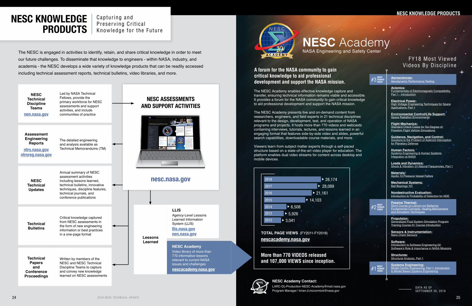
2018 NESC TECHNICAL UPDATE
The NESC is engaged in activities to identify, retain, and share critical knowledge in order to meet our future challenges. To disseminate that knowledge to engineers - within NASA, industry, and academia - the NESC develops a wide variety of knowledge products that can be readily accessed including technical assessment reports, technical bulletins, video libraries, and more.
NESCTechnical Updates
Annual summary of NESC assessment activities including lessons learned, technical bulletins, innovative techniques, discipline features, technical journals, and conference publications
AssessmentEngineering
ReportsThe detailed engineeringand analysis available as Technical Memorandums (TM)
NESCTechnical Discipline
Teams
Led by NASA TechnicalFellows, provide the primary workforce for NESC assessments and support activities, and include communities of practicenen.nasa.gov
ntrs.nasa.govntrsreg.nasa.gov
LLISAgency-Level Lessons Learned InformationSystem (LLIS)llis.nasa.govnen.nasa.gov
nesc.nasa.gov
NESC ASSESSMENTSAND SUPPORT ACTIVITIES
TechnicalBulletins
Critical knowledge capturedfrom NESC assessments in the form of new engineering information or best practicesin a one-page format
TechnicalPapers
andConferenceProceedings
Written by members of theNESC and NESC Technical Discipline Teams to capture and convey new knowledge learned on NESC assessments
The NESC Academy enables effective knowledge capture and transfer, ensuring technical information remains viable and accessible. It provides a forum for the NASA community to gain critical knowledge to aid professional development and support the NASA mission.
The NESC Academy presents live and on-demand content from researchers, engineers, and field experts in 21 technical disciplines relevant to the design, development, test, and operation of NASA programs and projects. It hosts more than 770 videos and webcasts containing interviews, tutorials, lectures, and lessons learned in an engaging format that features side-by-side video and slides, powerful search capabilities, downloadable course materials, and more.
Viewers learn from subject matter experts through a self-paced structure based on a state-of-the-art video player for education. The platform enables dual video streams for content across desktop and mobile devices.
24
NESC AcademyNASA Engineering and Safety Center
A C A D E M Y
N E S C
FY18 Most V iewed Videos By Disc ip l ine
Aerosciences:Aerodynamic Performance Testing
Avionics:Fundamentals of Electromagnetic Compatibility,Part 1 - Introduction
Electrical Power:High Voltage Engineering Techniques for SpaceApplications: Part 1
Environmental Control/Life Support:Space Radiation Environments
Flight Mechanics:Standard Check-Cases for Six-Degree-of-Freedom Flight Vehicle Simulations
Guidance, Navigation, and Control:Solutions to the Problem of Asteroid Interceptionfor Planetary Defense
Human Factors:Systems Engineering & Human SystemsIntegration at NASA
Loads and Dynamics:Shock & Vibration: 01.Natural Frequencies, Part 1
Materials:Apollo 13 Pressure Vessel Failure
Mechanical Systems:Ball Bearings 101
Nondestructive Evaluation:Introduction to Probability of Detection for NDE
Passive Thermal:Short Course on Lithium-ion Batteries:Fundamental Concepts, Heating Mechanismsand Simulation Techniques
Propulsion:Generalized Fluid System Simulation ProgramTraining Course 01: Course Introduction
Sensors & Instrumentation:Nano Chem Sensors
Software:Introduction to Software Engineering 02:Software’s Role & Importance in NASA Missions
Structures:Structural Analysis, Part 1
Systems Engineering:Model-Centric Engineering, Part 1: Introductionto Model Based Systems Engineering
NESC KNOWLEDGE PRODUCTS
NESC Academy Contact:[email protected] Manager | [email protected]
NESC KNOWLEDGE PRODUCTS
Captur ing andPreserv ing Cr i t ica lKnowledge for the Future
25
NESC AcademyVideo library of more than 770 informative lessons relevant to current NASA issues and challengesnescacademy.nasa.gov
LessonsLearned
A forum for the NASA community to gain critical knowledge to aid professional development and support the NASA mission.
DATA AS OFSEPTEMBER 30, 2018
N E S C
More than 770 VIDEOS releasedand 107,000 VIEWS since inception.
2015
2012
2016
2013
2017
2014
2018
3,041
5,926
6,508
14,103
21,161
28,089
28,174
TOTAL PAGE VIEWS (FY2011-FY2018)
nescacademy.nasa.gov
MOSTVIEWEDVIDEO
MOSTVIEWEDVIDEO
MOSTVIEWEDVIDEO
#3
#2
#1

Assessments:Typically include independent testing and/or analyses, the results of which are peer reviewed by the NESC Review Board and documented in engineering reports.
Support :Typically include providing technical expertise for consulting on program/project issues, supporting design reviews, and other short-term technical activities.
PRIORITY 2
PRIORITY 3
PRIORITY 4
PRIORITY 5
PRIORITY 1Projects in the flight phase
PRIORITY 2Projects in the design phase
PRIORITY 3Known problems not being
addressed by any project
PRIORITY 4Work to avoid potential
future problems
PRIORITY 5Work to improve a system
PRIORITY 1
2018 NESC TECHNICAL UPDATE 2726 2018 NESC TECHNICAL UPDATE
ASSESSMENT & SUPPORT ACTIVITIES: Pr ior i ty 1
ASSESSMENTS &SUPPORT ACTIVITIES
Technica l Assessments and Support Act iv i t ies Conducted by the NESC in 2018 ISS Cooling Pump
Bearing Wear LifeThermal control of the inhabited ISS volume is balancing between electrical power input from the solar array panels with waste heat rejection back into space through radiator panels. Pumps circulate liquid anhydrous ammonia through heat exchangers and cold plates to collect waste heat from ISS systems. The warmed liquid then cir-culates through the radiator panels to radiate the collected heat to space. An early failure of an ammonia cooling pump prompted an NESC assessment to determine the failure mechanisms and provide critical information to up-date the design life of the remaining spare pumps. To better understand long-life rotating machinery operating in microgravity environments, the assessment includ-ed an analysis of the rotor bearing system design space, examination of a range of uncontrolled manufacturing variables, and creation of a new database for wear data of bearings operating in liquid ammonia. An engineering tool was developed to predict the minimum mechanical life of the pump rotor bearing system. This work was performed by GRC and GSFC.
18%
67%
COMPLETED NESC REQUESTS in FY2018
Total 62The aircrew of F/A-18 aircraft, the U.S. Navy's high-perfor-mance land and carrier-based fighter jets, have reported physiological episodes (PE) during flight, and Naval Air Systems Command has been investigating the events to understand and mitigate their occurrence for several years. At the direction of Congress, the Navy requested NASA and the NESC conduct an independent review of the PEs and the Navy and Marine Corps' efforts to prevent them. The NESC focused on understanding the PE events, performing independent data analysis, and reviewing the Navy's investigative approach. This work was performed by AFRC, JSC, KSC, MSFC, WTSF, ARC, LaRC, GRC, WFF, USEPA, and NAVAIR.
Anomalous swelling behavior observed in the outer met-al canisters of some multi-purpose oxygen generators (MPOG), in storage for use in various naval systems, prompted an NESC assessment to evaluate the potential root causes of this swelling. The ISS relies on this technol-ogy for backup oxygen. This anomaly has potential impacts on the use of this technology in future NASA missions, which are considering MPOG technology for contingency oxygen storage. The NESC compiled facts and history on the MPOGs and performed testing to support identification of potential safety and performance impacts. This work re-sulted in recommendations to mitigate or correct the issue. Earlier NESC work on this subject is captured in NESC Technical Bulletin TB 09-05, available at nesc.nasa.gov.This work was performed by JSC, WSTF, and NAVSEA.
Oxygen Generator Swelling Anomalies
F/A-18 Fleet Physiological Events
Lithium-ion Battery Calorimetry
CAD Image of a Small Cell FractionalThermal Runaway Calorimeter
CELLCHAMBER
Includes heating system for thermally induced failure and mounting point for
nail penetration system
EJECTABORE
ASSEMBLIES
Slow downand extract heat from escaping flames and gas
The NESC has worked with the ISS Program and the EVA Project to improve the design of lithium-ion (Li-ion) batteries by lowering the risk of thermal runaway (TR) seen in some commercial applications. Building on that effort was the devel-opment of an in-house cell thermal runaway calorimeter that would characterize the rates, modes, and quantities of heat released from a cell in TR. Better quantification of the energy fraction liberated through the cell casing versus that vented as gases and other effluents is obtained using a newly designed calorimeter and is key to improving battery design and ther-mal analysis (see page 16). This work was performed by JSC, GRC, KSC and LaRC.
Priority 1Completed AssessmentsProjects in the F l ight Phase
The sun's energy is absorbed, converted into electricity, and transferred into the habitat.
Heat must actively be removed from the ISS and rejected through radiators.
Electricity heats the habitat.
ISS Backup Oxygen Candle System (4" x 4" square candle)
10%5%
10%5%
10%5%
F/A-18 flying over California's Mojave Desert
EJECTA MATING ASSEMBLIES
Capture ejectedsolids such as the electrode winding

292018 NESC TECHNICAL UPDATE28 2018 NESC TECHNICAL UPDATE
ASSESSMENT & SUPPORT ACTIVITIES: Pr ior i ty 2ASSESSMENT & SUPPORT ACTIVITIES: Pr ior i ty 1-2
• Juno Check Valve Anomaly Recovery Assessment• Deep Space Climate Observatory (DSCOVR) CompHub Reset Anomaly
Priority 1:Addi t iona l Completed Assessments
• Wallops Flight Facility Balloon Program Office Support• Wire Discoloration Tiger Team• Space Station Remote Manipulator System Latching End Effector Snare Cable Lubrication and Wire Breakage• Support to Launch Services Provider Hardware Reuse Assessment
Priority 1:Completed Support Act iv i t ies
Priority 2 Completed AssessmentsProjects in the Design Phase
Current and emerging scientific and human exploration programs continue to pose new technological challeng-es, causing avionics designers to push technologies to their physical limits. Budget and schedule pressures are causing a trend of compromising verification testing, thus challenging how technologies/missions are verified and forcing missions to adopt high-risk postures.
The NESC formulated an approach to verify design specifications under the expected Mission, Environ-ment, Application, and Lifetime (MEAL), given the risk posture adopted by the mission. The work describes the capabilities, advantages, and limitations of verification processes; related risks associated with various part-, board-, and box-level verification testing; and how risks can be managed for selection and verification of parts based on an integrated assurance approach focusing on MEAL and verification assurance (see page 22). This work was performed by GSFC, LaRC, WFF, and JPL. NASA-TM-2018-220074.
Guidelines for Verification Strategies to Minimize Risk Basedon Mission, Environment, Application, and Lifetime (MEAL)
Comparison of cost to test (top) and defect detection whenperformed at the box versus board versus part levels
Parts Board Box
Abilityto DetectInteractionBetweenParts
Abilityto
Detect Parts
Defects
max
min
Parts Board Box
Costand Schedule Impactto Fix
Costto
Test
max
min
MPCV Heatshield Material StudyDuring development and processing of the MPCV heatshield for the successful Exploration Flight Test-1 (EFT-1), the dis-covery of low strength and cracking issues led to an NESC assessment to determine the cause. The team performed a variety of tests, statistical analyses, and modeling to determine the root cause(s) of both low strength and cracking and whether the mit-igations proposed to resolve these issues would be effective. Evidence generated during the assessment uncovered oppor-tunities for general process improvements that would mitigate the risk of crack devel-opment and growth and improve materi-al strength. This work was performed by JSC, GSFC, ARC, LaRC, and MSFC.
NASA engineers from ARC and MSFC remove segments of Avcoat foranalysis from the surface of the Orion CM heatshield flown on EFT-1.
Static code analyzers can identify defects that have historically caused software failures.
NASA-developed autonomous flight termination software (AFTS) makes flight termination/destruct decisions based on configu-rable software-based rules using data from redundant Global Positioning System/Inertial measurement unit navigation sensors. An NESC assessment helped determine that static analysis could be applied to the AFTS software to improve quality and be used as part of acceptance criteria for future developments. Static program analysis is the analysis of computer software that is performed without actually executing programs. Static code analyzers use numerous heuristics to inspect the code for issues that have historically caused failures (see diagram). The tools report out where the flaw is located, the path taken to locate the flaw, and the issue type. This information can identify the correction necessary, and even the test case that could be added to the verification process. Static analysis was also applied to the AFTS core, which is currently flown on commercial cargo resupply flights to the ISS. Experience gained from the assessment supported Agency direction to apply static analysis techniques to software under development. Lesson Learned #24503 is based on this effort and is available at nen.nasa.gov. This work was performed by LaRC, JPL, and GSFC.
Static Software Analysis of AFTS
SOURCECODE UNDER
ANALYSIS
STATIC CODE ANALYZEREVALUATION FOR:
• Coding standard violations• Variable assignments• Potential out-of-bounds array index• Divide-by-zero possibilities• Questionable syntax• Consistency issues• Complexity measures• Unchecked input values• Other well-known defects that historically have caused failure
ERROR REPORTS• Code defects• Defects that impact code maintenance• Defects that produce security flaws
In-Progress Assessments• High-Pressure Composite Overwrapped Pressure Vessel Modeling Support• Pilot Breathing Assessment• Additional Characterization and Improvements of the Multi-Purpose Composite Overwrapped Pressure Vessel Liner Inspection System• Human Spaceflight-1 Mishap Recurring Factor Study• Independent Assessment of the Spacecraft Air Monitor System• Support of RRM3 Transfer Valve Issue• International Space Station Remote Power Control Module Hot Mate/Demate During Extra-Vehicular Activity
• Validation of International Space Station Lithium-ion Main Battery's Thermal Runaway Mitigation Analysis and Design Features• Express Logistics Carrier Reverse Capacitor Follow-on Testing• ISS Plasma Interaction Model Independent Review
In-Progress Support Activities
• Independent Anomaly Review of RD-180• TESS Fine Pointing Advisory Board Participation• GOES-S Loop Heat Pipe Anomaly Support• Rapid Slews for Lunar Reconnaissance Orbiter• Chandra X-Ray Observatory ACE Real-Time Data Support
Priority 1: Work in Progress

ASSESSMENT & SUPPORT ACTIVITIES: Pr ior i ty 2ASSESSMENT & SUPPORT ACTIVITIES: Pr ior i ty 2
PHOTO: Two 2001 images from the Mars Orbiter Camera on NASA's Mars Global Surveyor orbiter show a dramatic change in the planet's appearance when haze raised by dust storm activity in the south became globally distributed.
Automotive and Non-Automotive COTS EEE Parts TestingSelect NASA programs and organizations are considering using automotive and non-automotive commercial-off-the-shelf (COTS) electrical, electronic, and electromechanical (EEE) parts with no screening and qualification for avionics systems. Instead, alternate testing methods have been proposed. NASA typically procures EEE parts using military specifications. Parts made to these spec-ifications are built, screened, and qualified to the same standards by different manufacturers, regardless of the application or the pro-curement volume.
The NESC tested a variety of automotive and non-automotive COTS EEE parts to evaluate parts reliability in spaceflight appli-cations. Limited long-term life testing was performed, including de-structive physical analysis to determine parts construction quality and tests for environmental stress, life, and radiation susceptibility. Lesson Learned #23502 is based on this effort and is available at llis.nasa.gov. This work was performed by GSFC and LaRC.
Electronic Components
30 31
Dust in the Atmosphere of Mars and Its Impact on Human ExplorationWith the increasing focus on a crewed mission to Mars, many Mars-specific environmental factors are now being considered by NASA and other engineering teams. Learning from NASA’s Apol-lo missions to the moon, where lunar dust was a significant challenge to mission and crew safety, attention is now turning to the dust in Mars’ atmo-sphere and regolith. To begin identifying possible dust-caused challenges to human presence on Mars and aid engineering and design efforts, the NESC conducted a workshop attended by Mars scientists and engineers, mission architects, mis-sion planners, medical researchers, physicians, and toxicologists. The participants developed a prioritized set of key questions that address what is known about the physical and chemical prop-erties, abundance and composition of Mars dust, and its impact on human health and mechanical systems such as spacesuits and habitats. Areas for future study were also identified (see page 14). This work was performed by JPL, LaRC, and ARC. NASA-TM-2018-220084.
2018 NESC TECHNICAL UPDATE 2018 NESC TECHNICAL UPDATE
Exploration Systems Independent Modeling and SimulationBeginning in 2012, the NESC engaged in a long-term commitment and investment to assemble an independent, multi-year, multi-Center team that is building and maintaining the simulation architecture and expertise necessary to corroborate technical integration issues and risks identified by NASA's exploration programs. Modeling and simulation capabilities of the SLS and Orion MPCV have been developed to independently address issues throughout design, verification, and flight readiness cycles. Baseline modeling and simulation have incorporated vehicle updates for each SLS design and analysis cycle and more recently, verification analysis cycles.
Key products from the NESC work have included analysis of vehicle performance during lift-off and ascent, and analyses of critical separation events, including separation recontact analysis. In FY18 the NESC team analyzed SLS lift-off clearance from the mobile launch structure, solid rocket booster separation from the SLS core stage, separation of service module panels, and separation of the exploration upper stage from the SLS core stage. This work was performed by LaRC, GSFC, MSFC, and KSC.NASA/TM-2018-219841 and NASA/TM-2018-220092.
Separation of solid rocket boosters from the SLS core stage were analyzed for potential recontact as part of an NESC independent modeling and simulation effort to support the SLS Program.

332018 NESC TECHNICAL UPDATE32 2018 NESC TECHNICAL UPDATE
ASSESSMENT & SUPPORT ACTIVITIES: Pr ior i ty 2ASSESSMENT & SUPPORT ACTIVITIES: Pr ior i ty 2
Mitigation of NISAR Risk from MMODThe NASA-Indian Space Research Organisa-tion (ISRO) Synthetic Aperture Radar (NISAR) Project is a joint synthetic aperture radar-im-aging mission between NASA and ISRO, set to launch in 2020. The satellite will observe and measure some of the Earth’s complex natural processes, including ecosystem dis-turbances, ice-sheet collapse, earthquakes, tsunamis, volcanoes, and landslides. NISAR has exposed hardware that may be damaged by the micrometeoroid and orbital debris (MMOD) environment. The NESC performed a detailed review of the Project’s MMOD risk assessment and also assessed the risk to vulnerable components on the spacecraft. Additional mitigations were proposed to pro-tect vulnerable spacecraft components from MMOD impacts. This work was performed by LaRC, JSC, and JPL. NASA-TM-2018-219817.
Illustration of NISAR spacecraft with Synthetic Aperture Radar deployed
To investigate the “load and go” concept, the NESC assembled a team consisting of experts from the NESC, the NASA Safety Center, past human spaceflight programs, and six NASA centers. The team generated an independent fault tree analysis of the risks associated with propellant loading after the flight crew has ingressed. Design and operational controls and other planned mitigations were evaluated to determine if they adequately mitigated the identified risks. The hazard assessment also consid-ered issues that have occurred during cryo-servicing of other vehicles (e.g., Shuttle, Saturn, Atlas, etc.) and the safety-of-crew implications if similar issues were to occur during the proposed load and go operation. This work was performed by SSC, JSC, WSTF, GRC, KSC, MSFC and LaRC.
Load and Go Approachto Crew Ingress
Evaluation of SE&I Processes
Cross-Program Integrationand Mapping
Robust systems engineering and integration (SE&I) capabilities and processes are important throughout the system lifecycle to ensure safe and reliable system operations. They should facilitate systems thinking, provide insights into unexpected system-level interactions, provide an understanding of critical flight and ground system functions, and support management of system margins necessary for safe human spaceflight. The NESC was tasked to determine how the SE&I functions of NASA partners compare to those used by NASA in the waterfall approach to systems engineering.
Exploration Mission-1 (EM-1) depends upon the successful integration of the SLS launch vehicle/Orion MPCV with the Exploration Ground Systems (EGS), Mission Systems, and the Communications and Tracking Network. Each of these five systems contains many internal and external hardware and software interfaces. Successful integration means each system will interact with the others in predictable ways as designed to enable mission success. Major interfaces also exist between the five programs, increasing the cross-system/cross-program integration challenge.
Because the risks to integrating complex programs is well known, the NESC partnered with the Exploration Systems Development (ESD) Program’s Cross Program Integration Team Interface Functional Area to evaluate cross-pro-gram integration. The combined team jointly developed an evaluation meth-odology and framework to provide an initial assessment of the cross-program external interface integration and compliance. The methodology is also de-signed to provide continuous insight through the remaining system develop-ment lifecycle leading to flight certification. Using the methodological frame-work, a working set of cross-program functions were identified and modeled. Examination of these functions led to a systematic approach for analyzing the EM-1 cross-program external integration and compliance, with the objective to identify and mitigate existing verification and validation risks. This work was performed by GSFC, JPL, and MSFC. TM-2018-219798.
The NESC team developed a baseline model of nearly 200 SE&I functions to which otherdevelopers’ SE&I processes could be com-pared. The SE&I processes included re-quirements definition and analysis; systems analysis and margin management; risk man-agement and system safety definition and maintenance of natural and induced environ-ments; and integrated testing and analysis among others. This model assists in identi-fying equivalent functions and gaps in SE&I development models, e.g., waterfall or spiral. Lesson Learned #24502 is based on this ef-fort and is available at llis.nasa.gov. This work was performed by GSFC, JSC, KSC, LaRC, and MSFC. NASA-TM-2018-219798.
Cross-Program Interface Analysis Framework provided a systematic approach for analyzing cross-
program external integration and compliance
Mission Met Range
Critical Event
Model
validated in
used in
Phase Met Range
Segment Met Range
FBSFunction
RiskTitleRisk IDOwning OrganizationEscalation LevelEstimated Complete DateLikelihoodConsequence
VerificationClosure Notice
Submission DateDisposition DateDisposition Result
IV&V
ConfigurationItem
MilestoneDate
Program
TestObjective
Report / Test Plan
Planned DateRangeAcutal Date Range
DetailedVerificationObjective
Planned DateRangeActual Date RangeProgram
OMRSPlanned DateRangeAcutal Date Range
Hazard ID
LaunchCommit
Crit.Hazard
VerificationHazardControl
HazardCause
HazardReport
CrossProgram
RequirementJoint VR (yes/no)Joint VR LeadInterface (yes/no)LevelFBS MappingMET StartMET Stop
Development ProcessesImplementation
Unit/DeviceTest Plan
SubsystemVerification Plan
(Subsystem Acceptance)
System Verification Plan(System Acceptance)
System Verification Plan
Time Line
Retirement/Replacement
Changesand
Upgrades
Operationsand
Maintenance
Software / HardwareDevelopment
Field Installation
DetailedDesign
High-LevelDesign
SystemRequirements
Concept ofOperations
Unit / DeviceTesting
SubsystemVerification
SystemVerification & Deployment
SystemValidation
RegionalArchitecture(s)
Feasibility Study/Concept
Exploration
Decomposition and Definition
Inte
grat
ion
and
Reco
mpo
sitio
n
The NESC developed a model of SE&I functions to compare and contrastcommercial developers’ SE&I functions with those used by NASA.
During NASA’s previous human spaceflight pro-grams, flight crews have traditionally ingressed the spacecraft after the hazardous operation of loading cryo-propellant was complete and the launch vehicle was confirmed stable. Recently, a “load and go” approach was proposed that re-quires the flight crew to be on board the space-craft prior to the propellant-loading operation. Load and go was proposed to take advantage of performance benefits characteristic of lower temperature or “densified” cryogenic propellants, but has the limitation that the densified propellant warms rapidly and must be used with minimal de-lay, else the performance advantage is lost.
Shuttle crews were ingressed after hazardous cryo-fueling operations.STS-135 crew shown.

2018 NESC TECHNICAL UPDATE34
ASSESSMENT & SUPPORT ACTIVITIES: Pr ior i ty 2ASSESSMENT & SUPPORT ACTIVITIES: Pr ior i ty 2
Verification of SLS Stacking Loads PredictionsLoads and dynamics subject matter experts from the NESC and ESD engaged in a joint effort to verify independently SLS prelaunch analysis methodologies and loads predictions generated by the SLS Program and its contractor. A prelaunch stacking loads analysis is performed to compute the vehicle load indicators, including stacking-induced preloads, for all stacking stages. The stacking preloads are a part of the overall “twang,” which occurs during SLS pad separation at lift-off (i.e., strain energy relief at pad separation). The release of preloads can have a transient contribution to launch dynamics and overall lift-off pad separation.
An NESC-developed synthesis approach was used to simulated the physics of the stacking steps and computed load indica-tors, which includes preloads (refer to page 53 for details). All stages of stacking were simulated: the solid rocket boosters, core stage, and upper stage. The upper stage includes the launch vehicle stage adapter, interim cryogenic propulsion stage, and the Orion MPCV. A nonlinear transient coupled loads analysis was then executed on the prelaunch fueled configuration to gauge the response of the SLS to the sudden release of preloads and to gain insight into lift-off pad separation dynamics. This work was performed by JSC, KSC, and GSFC. NASA-TM-2018-220073.
Verification of SLS Turbulence/Gust Analysis for Ascent LoadsDuring atmospheric flight, launch vehicles and their payloads will experience significant structural loading from multiple, distinct sources, which can act simultaneously. A major contributor is turbulence/gust loads that are due to the non-persistent, short wavelength wind features encountered during atmospheric flight. These loads are computed for various Mach numbers, vehicle properties, wind features, and flight trajectories. The SLS Program recently implemented a new gust analysis methodology, replacing the synthetic gust analysis approach with a more rigorous and accurate one that incorporates turbulence/gust forcing functions extracted from measured wind altitude profiles.
Loads and dynamics subject matter experts from the NESC and ESD worked to perform an independent verification of the SLS implementation. The Aerospace Corporation (ASC) was engaged to verify the implementation since ASC had originally developed the methodology. The NESC/ESD team then performed additional analyses of the ASC results and made recommendations to the SLS Program that would help to ensure the accuracy of the computed loads for the SLS. This work was performed by JSC and LaRC. NASA-TM-2018-220086.
Illustration of MPCV stacking on the SLS
Illustration of SLS during atmospheric flight
352018 NESC TECHNICAL UPDATE
Illustration of SLS - Block 1 Expanded View
Solid Rocket Booster
Launch VehicleStage Adapter
Orion Stage Adapter
Interim CryogenicPropulsion Stage
Core Stage andVehicle Avionics
Orion Multi-PurposeCrew Vehicle

36
ASSESSMENT & SUPPORT ACTIVITIES: Pr ior i ty 2ASSESSMENT & SUPPORT ACTIVITIES: Pr ior i ty 2
The Role of Human System Integration in NASA Aeronautics
and X-plane Projects
The NESC performed an independent HSI Gap Analysis for the Low Boom Supersonic X-Plane. The principal focus of the as-sessment was to identify gaps in the current role of HSI in aeronautics projects, using the LBFD project as an example, and to help determine the appropriate level of HSI rigor to apply to current and future X-plane projects. As part of this work, the NESC team studied project-planning documents; NASA policy and DoD and FAA documentation; interviewed key personnel; and conducted site visits at AFRC and LaRC. This work was performed by ARC, LaRC, GSFC, and JSC. NASA-TM-2018-220083.
Illustration of the Low Boom Supersonic Demonstrator X-Plane. Credit: NASA-Lockheed Martin
With the goal of developing improved analysis tools and design approaches that enable development of supersonic airliners with very little perceived supersonic noise, the Low Boom Flight Demonstrator (LBFD) Project is building a piloted X-plane, leveraging 40 years of research in sonic boom minimization. Much of the Agency’s documentation concerning Human Systems Integration (HSI) is focused on the application of HSI principles to human spaceflight. The integration of humans into complex, safety-critical systems is key to miti-gating risk to mission success.
European Service Module being preparedfor testing in NASA’s Plumbrook Facility
Orion Propulsion Bellows Materials
CompatibilityBellows components in the Orion crew and service modules are critical components of flex-line piping assemblies that ab-sorb piping motion and help maintain pressure boundaries for propulsion fluid systems. Bellows operate in harsh fluid envi-ronments and reliable operation over the mission life is critical. The NESC supported development of a test program under-taken to better understand the material compatibility for thin pressure boundary materials and support the overall goal of improving bellows reliability for the certified usage life.
To characterize the bellows and their service life, a step-by-step evaluation of the bellows life from raw material through testing and flight operations was conducted. Knowledge gaps in the characterization, assumptions, and major unknowns were documented for the bellows design, material, processes, and environments. Compatibility predictions and a gap anal-ysis were then completed to generate recommendations for a supplemental analysis, test, and inspection program. This work was performed by KSC, GRC, JPL, LaRC, MSFC, GSFC, AFRL, WSTF, and JSC.
Evaluating Material Replacements forSpacecraft Propulsion Component Seals
IETM Demonstration for SLS
An O-ring material used as seals in storable propellant components on many NASA spacecraft designs was discontinued by the manufacturer and NASA's stockpiles will soon be depleted. The NESC initiated a materials compatibility character-ization effort to evaluate multiple replacement material options. The NESC tested and evaluated the material properties of multiple replacement candi-dates, looking at weight change, swelling, hardness, compression set and tensile strength in representative environments to help identify suitable re-placements. Materials testing was performed in accordance with NASA-STD-6001B, Flammability, Offgassing, and Compatibility Requirements and Test Procedures. A key test used from the standard was Test 15, Differential Pressure Immersion Test with Aerospace Fu-els. Test 15 is a short-term exposure test that identifies changes resulting from exposure to fluids that degrade either the material or the fluid or produce a reaction, which would cause the pressure in a closed sys-tem to rise. Test 15 is applicable to the hypergolic propellants commonly used in spacecraft propul-sion systems. The resulting performance data were entered into the Agency Materials Processes Technical Information System (MAPTIS) database and are available for use across multiple programs and projects. This work was performed by MSFC, JSC, and WSTF. NASA-TM-2018-220076.
Visualization tools are a critical part of the system design pro-cess and are widely used to create procedures that include in-structional video for operators, both in training and in systems operations. Integrated Electronic Training Manuals (IETM) were developed by the DoD for use by maintenance workers and vehicle operators. NESC human factors experts proposed that ground testing of SLS elements and deep-space systems may benefit from IETMs because infrequent SLS operations and deep-space missions will require retraining and familiarization to ensure safe operations.
The NESC effort involved identifying tasks that are typical of ground processing activities when a launch system is being assembled and maintained. Motion, posture video, and mod-els simulating tasks were then captured to create video, which can be viewed with Microsoft HoloLensTM hardware or from a computer monitor. The HoloLens type of augmented reality dis-play enables an IETM that can provide holographic overlays to insert instructions in the actual scene to support virtual training and operations maintenance while the user has complete free-dom of movement in the work area. This work was performed by ARC, MSFC, and SCC.
2018 NESC TECHNICAL UPDATE 37
User demonstrating a HoloLens-based IETM
Illustration of Test 15 apparatus from NASA-STD-6001B

3938 2018 NESC TECHNICAL UPDATE
ASSESSMENT & SUPPORT ACTIVITIES: Pr ior i ty 2ASSESSMENT & SUPPORT ACTIVITIES: Pr ior i ty 2
In-Progress Assessments
• Human Error Analysis Guide (NESC Position Paper)• Launch Abort System Risk Mitigation (Special Study)• Aerospace Valve Industrial Base and Acquisition Practices • Human Factors Analysis of Test Stand Operations • Composite Pressure Vessel Working Group• Stress Ruptures Composite Overwrapped Pressure Vessel• Assessment of Autonomous Flight Termination System• Composite Overwrapped Pressure Vessel Overwrap Testing• Composite Overwrapped Pressure Vessel Grain Size• Main Parachute Nondestructive Eval.• Parachute Pack Ground Extraction Testing • Thermal Protection System Spray-On Foam Insulation Testing• Ascent Cover Separation System• Stress Rupture of Composite Overwrapped Pressure Vessel Composites in LOX and RP-1• Propellant Tank Safe-Life Analysis• Capsule Dynamics in the NASA Langley Research Center 20-Foot Vertical Spin Tunnel Assessment• Commercial Crew Program Aerodynamics Peer Review• Viscous Effects on Launch Vehicle Ground Wind-Induced Oscillations• Evaluation of Occupant Protection Requirement Verification Approach by Commercial Crew Program Partners• Assessing Risks of Frangible Joint Designs• Independent Modeling and Simulation for Commercial Crew Program Entry, Descent, and Landing• Launch Availability Model Independent Assessment• Exploration Ground Systems Mobile Launcher Structures Model Peer Review• Characterization of Thick Section Aluminum-Lithium 2195 Natural Aging• Independent Verification of Space Launch System Block 1 Pre-Launch, Liftoff, and Ascent Gust Methodology and Loads• NESC Peer Review of Exploration Systems Development Integrated Vehicle Modal Test, Model Correlation, DFI, and Flight Loads Readiness• Exploration Systems Independent Modeling and Simulation• Spacecraft Safety Equipment Assessment
• JWST Space Environment Launch Constraints• Effects of Humidity on Dry Film Lubricant Storage and Performance• Material Compatibility and EAC Data for Metals in Hypergolic Propellants• Feasibility of Ultrasonic Level Sensors for Exploration Service Module MKII Propellant Tanks• Orion Simulator Risk Assessment• Orion Multi-Purpose Crew Vehicle Titanium Hydrazine Tank Weld - Sustained Load Cracking Issue• Application of System Identification to Parachute Modeling• Infrared Laser Sensor Technology Readiness and Maturation• Risk Reduction of Orion Government- Furnished Environmental Control/Life Support System• Peer Review of the Multi-Purpose Crew Vehicle Aerodynamic/Aerothermal Database Models and Methods• Assessment of Lead H2 Pop during Space Launch System RS-25 Start• Space Launch System Liftoff Environment Models• Space Launch System Program Block I Booster Element Alternate Internal Insulation Risk Reduction• Nonlinear Slosh Damping Analysis for Launch Vehicles• Space Launch System Aerosciences Independent Consultation and Review• Agency Systemic Manufacturing and Processes Issues• Reaction Wheel Performance for NASA Missions
In-Progress Support Activities
• Power Electronics Technical Support for Electric Propulsion• Modeling, Testing, and Analysis for Investigation into Composite Over- wrapped Pressure Vessel Liner Leaks• Coordinated Review of LO2 Loading Systems• Parachute Anomalies Investigation • Post Hot-Fire Metallic Panel Analysis• NESC Support to Commercial Crew Program Composite Overwrapped Pressure Vessel 2.0• Support for Commercial Crew Program Parachute Flight/Ground Tests and Vendor Packing/Rigging Activities• Super Resolution Post Processing of Air- to-Air Imagery of Commercial Crew Program High Altitude Parachute Test• NOVICE Support to Launch Services Provider and Commercial Crew Program Radiation Assessment
• Review of Propellant Tank Composite Overwrapped Pressure Vessel Anomaly and Path Forward• Analysis and Test of Space Launch System Core and Booster Stage Flight Termination System Batteries• Subject Matter Expert Support for DSG Early Systems Engineering and Integration Review• Space Launch System Booster Nozzle Throat Plug Debris• Accelerance Decoupling for Modal Test• International Space Station Research Activities outside the Microgravity Science Glovebox• Orion Crew Module/Service Module Separation Nut Test Fixture Failure• Orion Crew Module Recovery during Underway Testing and Exploration Mission-1• Orion Exploration Mission-2 Spectrometer• Hydrodynamics Support for the Orion Crew module Uprighting System• Orion Crew Module/Service Module Separation Bolt Life issue• Orion Crew Module Well Deck Recovery Conditions Dynamics Analysis• AA-2 Independent Review Team• Bond Verification Plan for Orion's Molded Avcoat Block Heatshield Design• MAF Nonconformance Reporting and Corrective Action Technical Support• Space Launch System Systems Engineering and Integration Certification of Flight Readiness Support• MSFC Engineering/SMA Support for Uncertainty Quantification• Waterflow Pulse Test Support to Develop RL-10 Pogo Model Propulsion Terms• NDE Support for Space Launch System Weld Anomalies• Support for Space Launch System Design Certification Review• Wallops Flight Facility Super Pressure Balloon Data Acquisition Design Support• Support Mars 2020 Heatshield Structural Failure Review• Adiabatic Demagnetization Refrigeration on SOFIA Science Instruments• Peer Review of Parker Solar Probe Guidance, Navigation, and Control Verification Test Case Status• Europa Lander Radiation Test• Independent Materials Expert Review of Parker Solar Probe C103 Niobium Sublimation Model• Affordable Vehicle Avionics Global Positioning System Testing Support
Priority 2: Work in Progress
• Commercial Crew Program Configuration Management Support• Support for Sierra Nevada Dream Chaser Thermal Protection System FDDR• Propellant Landing and Orbit Tank Failures• CCP Incremental Risk • Commercial Resupply Vehicle Structural Design Review Support• Cold Atom Laboratory Vibration/Dynamics• Support Parachute Test Anomalies Investigation • Support for Evaluation of Space Launch System Program Polarity Testing Approach• Space Launch System Block 1B Guidance, Navigation, and Control Design Review
• Commercial Crew Program Request for Pyroshock Support• Report on the workshop "Dust in the Atmosphere of Mars and its Impact on Human Exploration"• ECOSTRESS Vibe Failure - Failure Review Board Support• Support Mars 2020 Parachute Test at NASA Wallops• Space Launch System Pyro Firing Incident• Orion Propellant Gauging• Space Launch System Integrated Spacecraft Payload Element Modal Test Assistance• M2020 MEDA SkyCam EGSE Analysis
• Support in Conducting Atlas V Battery Hazard Test• Design of Experiments Support for Commercial Crew Program Arc Jet Testing• Materials Technical Discipline Team Support for Orion Crew Module US• Electrical Power for High-Voltage Direct Current Battery Close-Call Investigation at Armstrong Flight Research Center• Exploration Service Module Major Propulsion Design Upgrades• B-2 Space Launch System Green Run Handling Processes• Test Matrix for Arc-jet Testing
• Evaluation of Exceptions for Etchant Use Prior to Dye Penetrant Inspections• COPV Densified LOX Compatibility
• Burst Factor Assessment for Pressure Vessels• Human Factors Review of SGSS Project
• Evaluation/Validation of Range Safety BLASTDFO Model
Priority 2: Addi t iona l Completed Assessments
Priority 2: Completed Support Act iv i t ies
2018 NESC TECHNICAL UPDATE

2018 NESC TECHNICAL UPDATE 4140
ASSESSMENT & SUPPORT ACTIVITIES: Pr ior i ty 3-5ASSESSMENT & SUPPORT ACTIVITIES: Pr ior i ty 3
Shell Buckling Knockdown Factor ProjectThe NESC Shell Buckling Knockdown Factor (SBKF) Project is developing and experimentally validating new analysis-based shell buckling design guidelines, and specifically buckling knockdown factors (KDF) for metallic and composite launch vehicle structures. These new knockdown factors will enable significant weight savings and will help mitigate launch vehicle development and performance risks. The initial SBKF efforts focused on integrally stiffened metallic cylinders such as those found in launch-vehicle liquid oxygen and liquid hydrogen tanks, or in launch vehicle dry structures such as intertanks or engine sections. This metallic portion of the SBKF Project is nearly complete, and the first draft of the revision to the NASA SP-80071 is complete and ready for peer review.
The bulk of the current SBKF effort is now focused on the buckling response of cylindrical sandwich composite structures of the type that will likely find use in launch vehicle dry structures. The team released an NESC Technical Bulletin in 2017 to caution designers that KDFs derived for metallic cylinders are not directly applicable to composite cylinders. As such, a series of 8-ft diameter cylindrical tests are being conducted to validate the buckling analysis methods being used for composite KDF development. During the past year, the second such test was conducted and a design review for the next two test articles was successfully completed. In addition to these large-scale cylinders, other small-scale cylinders are being fabricated and tested as part of collaborative work that SBKF has with Delft University of Technology in the Netherlands. These small-scale cylinders will be used to study the effects of scaling on the buckling response of sandwich composite cylinders.
The SBKF team has also been working with the SLS Universal Stage Adapter Team with respect to their buckling design ap-proach for the proposed sandwich composite cylinder-cone structure. Finally, 10 papers on shell buckling test and analysis were authored or coauthored by SBKF team members and presented at the 2018 AIAA Science and Technology Forum and Exposition (SciTech) in Kissimmee, FL.
Reference: 1. Anonymous: Buckling of Thin-Walled Circular Cylinders.NASA Space Vehicle Design Criteria, NASA SP-8007, 1965 (revised 1968).
Priority 3 Completed Assessment
Completed Support Activities• Navigation Doppler Lidar - Peer Review• Additive Manufacturing Structural Integrity Initiative Project Oversight
In-Progress Assessments• Creation of Agency Standards for Additive Manufacturing • Calorimetry for Large Format Lithium- Ion Cell Thermal Runaway• Safe, High Power Li-ion Battery Module Design• Composite Overwrapped Pressure Vessel Life Test• CubeSat Radiation Environments and ISS Radiation Dose Data• Micrometeroid/Orbital Debris Pressure Vessel Failure Criteria• J-A Methodology Crack Instability Analysis Capability into WARP-3D Code• Space Weather Architecture• Shell Buckling Knockdown Factor Proposal• Human Systems Integration for Safety- Critical Range Operations at WFF• Guidelines for Battery Thermal Runaway on Robotic Missions• Rad750 Qualification Testing
In-Progress Support Activities• 6 Degree-of-Freedom Trajectory Simulation with Integrated Computational Fluid Dynamics Aerodynamics• Technical Support for Completion of NASA-HNBK-5010A• Exploration Ground Systems Crawlerway Geotechnical Support• Liquid Methane/LOX Explosion Characterization Planning Peer Review
Completed Support Activities• Additive Manufactured Fuel Turbopump Disassembly/Inspection and Post-Test Data Evaluation
In-Progress Assessments• Human Performance Contributions to Safety in Commercial Aviation• Solderless Interconnects and Interposers• Assessment of Electrical, Electronic, and Electro-Mechanical Parts Copper Wire Bonds for Space Programs
In-Progress Support Activities• State of In-Space Propellant Tanker/ Transfer Technology• Peregrine Sounding Rocket Redesign• Fluid Structure Interaction in Prediction of Parachute Performance
Completed Assessments• Empirical Launch Vehicle Explosion Model Evaluation
Completed Support Activities• Fracture Control Standard and Handbook (NASA-STD-5019A)
In-Progress Assessments• Assessment of Spacecraft Passivation Techniques• Flight Mechanics Analysis Tools Interoperability and Component Sharing• Flexible Multibody Dynamics Modeling for Space Vehicles• Reliable Method to Reason about Mass Growth• Radiation Single Event Effects Impact on Complex Avionics Architecture Reliability• Improved Design and Optimization of Complex Trajectories• Fast Coupled Loads Analysis via Norton-Thevenin Receptance Coupling • DSCOVR PHA Data Analysis• Improvements to the Flight Analysis and Simulation Tool (FAST)
In-Progress Support Activities• Technical Support for DARPA - TRADES Study• US Army: Reentry Aeroballistics Trajectory and Thermal Protection• Determining the Composition and Depth of the Lakes on Titan
Fabricated composite shells in the MSFC Composites Technology Center
Removal of 8-ft-diameter composite cylindrical test article from fabrication tool at MSFC
2018 NESC TECHNICAL UPDATE
Priority 3:Known Problems Not Be ing Addressed by Any Project
Priority 4:Work to Avoid Potent ia lFuture Problems
Priority 5:Work to Improvea System
Fabrication of 8-ft-diameter composite cylindrical test article by automated fiber placement at the MSFC Composites Technology Center

Kenneth R.Hamm, Jr.NESC Chief Engineer
24 ARCemployees supported NESC work in FY18
Humans have a powerful rolein adding to the reliability of a system, adding common sense and survival instincts in ways machinery cannot.We do not want to automate humans out the system because then you remove the human potential for making systems more reliable, safe, and resilient.” - Dr. Alan Hobbs
2018 NESC TECHNICAL UPDATE 43
The Ames Research Center (ARC) supports many NESC key activities, leverag-ing its unique and diverse capabilities including: advanced computing; aerodynamics testing; automation; computational fluid dynamics (CFD); entry descent landing (EDL) modeling; testing advanced thermal protection materials; and human factors research. Many ARC experts supported major technical assessments and TDTs throughout 2018. ARC has representatives on 18 NESC TDTs. ARC provides independent EDL modeling for the CCP using expertise in aero-thermal analysis and high speed computation. ARC engineers support major discipline reviews for CCP, Orion, and SLS. ARC assists with launch thrust and lift-off CFD simu-lation of SLS engines and solid rocket boosters for the mobile launcher structural mod-eling technical review. The Human Factors discipline uses ARC expertise to assess human-in-the-loop safety concerns regarding engine testing programs and schedules at SSC. The Technical Fellow for Human Factors is located at ARC.Designing for Human Capabilities Dr. Bettina Beard is with NASA’s Human Research Program where her current work has her traveling to multiple military bases administering cognitive and fine-motor tests to more than 200 pilots to obtain normative data comparable to peak astronaut perfor-mance. “Anytime you have humans involved, a human factors assessment is critical to risk mitigation,” she said. Whether humans are writing software, building hardware, operating equipment, or flying aircraft or spacecraft, understanding how people behave and respond to their environments and designing for human capabilities and limitations is critical to mission success. Dr. Beard has participated in numerous NESC assessments involving human fac-tors, most recently in an evaluation of the A-1 and E-1 Test Stands at SSC, where the rocket engines that will carry vehicles and astronauts to space are put through the rig-ors of testing. At the E-1 complex, up to three articles can undergo testing at one time.Dr. Beard and her team interviewed the employees, studied procedure use, evaluat-ed design, and observed operations to identify the factors that contribute to workload stress and fatigue and recommended how to mitigate the inherent risks associated with such a large operation. She performed similar work for the ISS Program. That team established tailored best practices for organizational resilience. Her NESC work also involves the study of procedures in use at all NASA Centers. “Understanding how a team writes and uses procedures and providing guidance to improve these practices can help avoid mishaps and procedure-related incidents.” “It’s amazing how dedicated everyone is at every Center I visit. They love their jobs, and if something is wrong, they want it fixed. And we’re able to help them.”Factoring in Human Potential A senior researcher at the San Jose State University Research Foundation, Dr. Alan Hobbs is a contractor supporting the Human Systems Integration division at ARC. He specializes in human factors, particularly in the area of maintenance. “I’ve focused on people who often get overlooked, those doing maintenance in hangars or in ground processing who perform a great amount of touch labor.” Currently, Dr. Hobbs is supporting several NESC human factors assessments, in-cluding the development of a human error analysis guide. This analysis is required by NASA for human-rated space launch systems, and his team is tasked with providing guidance on how and what to analyze. “There are thousands of tasks to be done to prepare a spacecraft for launch, and we must identify the key activities that could be the most problematic or are the most prone to human error.” He is also helping to develop a human factors training course for design engineers. “We’re putting ourselves in the shoes of a technician who interacts with equipment to help anticipate problems so we can remove them in the design stage rather than during training, in procedures, or by adding warning labels.” Another assessment has him working with pilots of remotely-piloted systems to understand the role of humans in automated systems. “Humans have a powerful role in adding to the reliability of a system, adding common sense and survival instincts in ways machinery cannot. We do not want to automate humans out the system because then you remove the human potential for making systems more reliable, safe, and resilient.”
Dr. Bettina Beard
Dr. Alan Hobbs
NESC ATTHE CENTERS
Drawing Upon Resourcesfrom the Ent i re Agency
NESC AT THE CENTERS: Ames Research Center
Langley Research Center
Ames Research Center
Kennedy Space Center Marshal l Space F l ight Center
Armstrong F l ight Research Center
Glenn Research Center
Goddard Space F l ight Center
Johnson Space Center
Jet Propuls ion Laboratory
Stennis Space Center

The Armstrong Flight Research Center (AFRC) provided engineering technical expertise and continued support of numerous NESC activities including: characteriz-ing the structural performance of composite overwrapped pressure vessels (COPV) in densified liquid oxygen to simulate launch conditions; using fiber optic strain sensor ar-rays to establish the veracity of structural boundary conditions to determine knockdown factors for composite shells subjected to buckling loads; and supporting test technique development for the hot mating/demating of remote power control module during an EVA on the ISS. One new activity has come as a result of NESCs efforts in 2017 to help the U.S. Navy better understand the reason for marked increases in so-called “physio-logical episodes,” which have been increasing in military jets in recent years. AFRC and the NESC have embarked on a new flight test campaign to gather missing information regarding pilot breathing to help shed light on the human-machine interaction during high-performance flight.Understanding the Human-Machine Interface As a test pilot for NASA, Mr. James Less is working with the NESC on an assess-ment to help the U.S. Navy better understand physiological episodes that have occurred across their F/A-18 fleet. The effort will provide insight into pilot physiology and interac-tions with the high-performance aircraft’s modern oxygen systems. “Using a traditional liquid oxygen system during testing will allow the researchers to focus in on the pilot physiology and how our breathing needs change during different phases of flight,” said Mr. Less, who is helping the NESC determine how the flight tests will be conducted and ensuring appropriate safety measures are in place. Retired from the U.S. Air Force,Mr. Less knows the importance of the data they collect. “We understand how critical it is for our military aircrews to have complete confidence in their oxygen systems. We hope our research will shed light on the problem and lead to a solution so they can stay focused on their mission of defending our country.”Testing for the Harsh Environments of Space Dr. Patrick Chan’s expertise in fiber optic (FO) systems and materials science is critical to the NESC’s understanding of how COPVs will respond in the harsh environ-ments of space. Using a NASA-developed technology called Optical Frequency Domain Reflectometry, which Dr. Chan has been working to mature, multiple FO sensors were applied to a COPV to measure its response to pressurization of up to 7,000 psi while submerged in a cryogen such as liquid nitrogen. “You are putting that material into a cold environment where it will want to shrink but also expanding the material by filling it. It’s a complicated measurement in a very hostile environment, but the FO sensors were able to give us the readings we needed,” he said. “Before each test, we don’t know if fi-ber will survive, but it worked throughout and that was rewarding. Seeing the technology that you fostered work and provide valuable data was an enjoyable part of this work.” Drawing from a Broad Range of Electrical Power Expertise Mr. Sean Clarke, Advanced Research Systems Engineer at AFRC, brings his know-ledge of electronic systems development for research aircraft to the NESC’s Electrical Power TDT. “It’s been a good place to get some cross pollination between Centers and electrical disciplines that don’t always overlap,” he said. As NASA’s X-57 principal investigator, he has found input from team members beneficial to his work. “It’s our first all-electric X-plane. It has a huge battery system and large electrical motors. When our first prototype battery system wasn’t doing well enough to keep thermal runaway from happening, the TDT offered support during the redesign process.” Mr. Clarke also assisted in an NESC assessment of a high-voltage battery incident at AFRC that resulted in better control planning and processes. “It was another case where AFRC had a process for dealing with short-term implications, but the NESC was helpful with longer-term considerations. It’s nice to have the NESC around as an independent engineering organization we can go to for advice or specific challenges.”
The Glenn Research Center (GRC) provided a broad spectrum of technical exper-tise in support of 19 NESC assessments and 18 of the NESC TDTs. These activities supported all mission directorates as well as several cross-cutting discipline activities. Significant GRC contributions this year were in support of propellant gauging for the Orion Service Module (SM) as well as support for compatibility of COPVs with liquid oxygen. The Technical Fellows for Cryogenics and Loads and Dynamics, as well as deputies for the Propulsion, Electrical Power, Systems Engineering, and Nuclear Power and Propulsion TDTs, are resident at GRC.Gauging Propellant in Low Gravity Fluids like rocket propellant behave much differently in space. Without gravity to hold the fluid to the bottom of the tank, there is no easy way to determine how much fuel remains in the tank. “It’s like going on a road trip without a gas gauge,” said Dr. Greg Zimmerli. “And the uncertainty grows as you deplete your propellant.” In his work at the GRC Fluid and Cryogenic Systems Branch, Dr. Zimmerli has developed a technique to gauge propellant quantity in low gravity environments that will be put to the test on a robotic refueling mission in November. Given his unique background and expertise, the NESC recently selected him to participate in assessments to address propellant quantity sensing methods for the Orion SM as well as assessing the feasibility of an ultrasonic sensor technology for use with the SM propellant tanks. “Every tank has its own challenges, and not just with low gravity. For Orion, devel-oping sensors that will work without a tank penetration is the big challenge. We have a group from KSC, GRC, JSC and an outside acoustics expert to work this ultrasound assessment. It’s great to hear everyone’s ideas and work out solutions.” Further devel-opment of gauging technologies will aid in NASA’s monitoring of propellants in space exploration missions, he said, from quantity sensing, to the transferring of these liquids in space. “It could help enable future missions such as a space propellant depot.” Dr. Zimmerli enjoyed the challenge of working the low gravity fluid dynamics issues for the NESC. “They bring together people from various Centers and you meet people from different backgrounds with similar interests. The assessments are typically a fo-cused topic over a short duration. You go in, attack the problem, and see where it goes.”Mitigating Risks of COPVs For more than 10 years, Mr. Eric H. Baker has been a member of the GRC’s COPVs Mechanics Team providing expertise to the NESC’s ongoing work to assess and miti-gate risks associated with COPVs. Ensuring safety and reliability, these assessments have supported a variety of flight programs including the Space Shuttle, ISS, Orion, Commercial Cargo and Crew, Chandra, and Juno. As a contractor for GRC’s Ceramic and Polymer Composites Branch, Materials and Structures Division, Mr. Baker’s work in structural analysis and modeling of composites and advanced material systems has fit nicely into these assessments. The suite of an-alytical methods and tools he has developed have helped to efficiently model COPVs and have been leveraged in new hardware game-changing pathfinders such as the Composite Cryotank Technology Development Program and the Composite Nanotube COPV Flight Test. Recently he assisted the NESC by providing independent analysis of vendor-man-ufactured COPVs. “As part of my work with the NESC, I double-check the vendor’s stress analyses, which often requires development of an independent numerical simu-lation model.” His work also involves calibrating these models to full-scale COPV testing performed at other NASA Centers. “This exercise gives us a good handle on how the component is going to perform and whether it will be safe.” As a consultant to the NESC COPV Working Group, Mr. Baker plays an active role in the NESC’s multi-disciplinary COPV assessment teams. He regularly works with JPL, JSC, KSC, LaRC, MSFC, WFF, and WSTF and enjoys the opportunity to collaborate with experts from across NASA. “Each project has its own unique set of challenges, and the teams’ successes often come down to a complete group effort.”
Dr. W. LanceRichardsNESC Chief Engineer
33 AFRCemployees supported NESC work in FY18
Robert S.JankovskyNESC Chief Engineer
71 GRCemployees supported NESC work in FY18
James Less
Dr. Patrick Chan
Sean Clarke
Dr. Greg Zimmerli
Eric Baker
NESC AT THE CENTERS: Armstrong F l ight Research Center NESC AT THE CENTERS: G lenn Research Center
Each project has itsown unique set of challengesand the teams’ successesoften come down to acomplete group effort.” - Eric Baker

The Jet Propulsion Laboratory (JPL) provided technical leadership and engineer-ing expertise in COPV, avionics, miniature sensors, mechanical structures, thermal sys-tems, and MBSE to 27 assessments in 2018. Work supported the U.S. Naval Air Sys-tems Command and both the Science and Human Exploration and Operations Mission Directorates. In addition, JPL supported each TDT on the advancement of Agency-wide engineering initiatives and standards. The NESC Chief Scientist, along with Space En-vironments and GNC TDT deputies, also reside at JPL.Developing Sensors to Measure Pilot Breathing JPL engineers Dr. Ryan Briggs and Dr. Lance Christensen are developing sensors to measure the carbon dioxide and oxygen that is delivered to U.S. Navy, U.S. Air Force, and NASA pilots during flight as part of an NESC assessment to address physiological episodes experienced in various jet fighter aircraft. Data collected may help provide in-sight into the episodes. “The most challenging part is finding a sensor location as close as possible to breathing masks without impeding or adding weight to pilot equipment,” said Dr. Briggs. The prototype sensors are currently being tested and will soon be inte-grated for flight tests. Both engineers have enjoyed the project because of the fast turn-around required. Other sensors they have developed for spacecraft will not fly for several years and this project allows them to quickly see the sensors in their final application. Re-Architecting NASA's Wire Derating Standards Mr. Ben Furst, Dr. Elham Maghsoudi, Ms. Emma Nelson, Ms. Antonietta Conte,Mr. Anthony Bautista, and Ms. Subha Comandur designed a thermal test apparatus and conducted tests that will help validate NESC thermal computational models that may supersede decades-old wire derating standards. The time intensive tests involved care-fully assembling and instrumenting many combinations of wire bundles and placing them in a thermal-vacuum chamber that simulates the space environment. Electrical current was sent through the bundles and wire temperatures were measured. “Thermal models will more accurately predict the heat generated, making wire selection less conservative and potentially saving significant weight on spacecraft,” said Mr. Furst. Mr. Bautista, a mechanical engineering student, developed a 3D model that ensured the pattern for the wire bundles was maintained during testing, prepared test articles, and collected data. “Getting hands-on experience with the hardware was definitely a new experience for me.” Flexible Body Dynamics Models Dr. Aaron Schutte and Dr. Abhinandan Jain are developing a toolchain that will streamline and simplify the way complicated flexible multibody dynamics models are generated. The new process simplifies the task of extracting these models from NAS-TRAN-based structural analysis models for use in multibody dynamics simulation tools such as JPL’s Dynamics And Real-Time Simulation (DARTS) toolkit. “At the DARTS Lab, we have a multimission simulation framework that we use to develop vehicle level dynamics simulations,” said Dr. Schutte. The NESC assessment has allowed them the opportunity to cross-validate their efforts with MSFC and apply the theories behind flexible multibody dynamics modeling to a broader range of vehicles and platforms, he said. “I’ve enjoyed the work we’ve been doing with Marshall and the chance to see what other Centers are doing.”Determining Cause of Anomalous Discolorations Mr. Virgil Mireles, manager for the JPL Propulsion and Materials engineering sec-tion, supported the NESC in evaluating and assessing potential risk from anomalous discolorations seen on wires with translucent insulation. This wire is used for flight ca-ble harnesses and electronic boards. “We needed to sample several miles of wiring to ensure we understood all of the different wire configurations and to determine suscepti-bility to corrosion and risk to ongoing flight missions.” Through a combination of optical assessments, chemical analysis, and spectrography, the team found the discoloration to be benign with a negligible risk to flight missions. The team successfully ruled out any concerns of a corrosion called Red Plague, typically brought on by the presence of moisture and oxygen, which can damage copper conductors and lead to catastrophic failure of system electronics.
The Goddard Space Flight Center (GSFC) continued to extensively support NESC activities in 2018, providing expertise with 80 engineers, technicians, and scientists. GSFC is the resident Center for the NASA Technical Fellows for Systems Engineering, GNC, Mechanical Systems, and Avionics. Significant contributions this year were in support of Radiation Single Event Effects Impact on Complex Avionics Architectures, Cubesat Radiation Environment and ISS Radiation Dose Data, Independent Materials Expertise for the Parker Solar Probe Project Niobium C-103 Risk, Solderless Intercon-nects and Interposers, and WFF Super Pressure Balloon Data Acquisition Design.Managing Complex Systems with MBSE As NASA missions grow in complexity, managing these programs throughout their lifecycles and maintaining the large volume of documents and databases that can span multiple systems and disciplines becomes more challenging. Ms. Jessica Knizhnik, the co-lead of the Agency’s MBSE Infusion and Modern-ization Initiative (MIAMI), expects this ongoing initiative will offer options to make the management and development of these complex programs and projects easier. “The goal is to infuse MBSE into the workforce and make it something that’s valuable for engineers across NASA.” MIAMI is currently working toward a targeted deployment for MBSE in 2020 to gain formal feedback from users on which aspects of MBSE are useful in a production release-like environment. “We want them to use the portions of MBSE that work for them and expect to see three main benefits – enhanced knowledge transfer, improved communication, and eas-ier management of complex systems.” MIAMI takes Ms. Knizhnik across the Agency as she works with different projects at various Centers to help them implement MBSE. It also allows her to share what she knows about GSFC missions and bring her knowledge of other Centers back home. “It has been eye opening to see how other Centers do business and how my Center fits into the bigger picture. I like being able to innovate, try out new ideas, and see the fruits of my effort. The strong technical team that we have built results in a successful improvement of the way that we execute systems engineering and NASA missions. It is very rewarding.”Investigating Solderless Technology Mr. Milton Davis is a structural and thermal electronics packaging systems design-er and consultant leading the design of multiple systems across the Agency including instruments, attitude control systems, and command and data handling systems. As the technical lead for an NESC assessment, he is evaluating the use of solderless intercon-nects to replace or supplement the need to solder large processor devices on printed circuit board assemblies. “In the development of state-of-the-art electronics systems, we are constrained by the solder assembly process. If we want to grow the technology, we need to look for different ways to connect these processors to our circuit board assemblies. Solderless technology is one potential solution.” Today’s systems require processors that can handle a large amount of output/input from a small device, which is getting harder as devices get even smaller and circuit boards are more densely packed. “The assessment is investigating industry devices that NASA may be able to use to replace or augment solder devices.” Mr. Davis is also supporting another assessment to evaluate mass margins on NASA spaceflight programs. “We are collecting information from various mission system engineers to assemble a history of mass data so we can figure out the key drivers of mass growth and help reduce that risk on future projects,” he said. “Until I participated in these assessments, I didn’t realize how deep the knowledge is across disciplines and across Centers. It has expanded how I think about a problem, isolate variables, and attack problems to find solutions that will fit the Agency as a whole, not just from my Goddard perspective.”
George L.JacksonNESC Chief Engineer
80 GSFCemployees supported NESC work in FY18
Kimberly A.SimpsonNESC Chief Engineer
91 JPLemployees supported NESC work in FY18
Dr. Lance Christensen Left
Dr. Ryan Briggs Right
Left to Right:
Gregory Keller, Saverio D'Agostino, Manuel Gallegos (in chair), Mark Hetzel, Richard Blank, and Virgil Mireles
NESC AT THE CENTERS: Jet Propuls ion LaboratoryNESC AT THE CENTERS: Goddard Space F l ight Center
Dr. Aaron Schutte Left
Dr. Abhinandan Jain Right
Jessica Knizhnik
Milton Davis
Until I participated in these assessments, I didn’t realize how deep the knowledge is across disciplines and across Centers. It has expanded how I think about a problem, how I isolate variables, and attack problems to find solutions that will fit the Agency as a whole, not just from my Goddard perspective.” - Milton Davis
Wire Derating Assessment TeamTop left to right: Ben Furst (Team Lead), Anthony Bautista, Bottom left to right: Emma Nelson, Antonietta Conte,Elham Maghsoudi, and Subha Comandur (not shown)

The Johnson Space Center (JSC) and the White Sands Test Facility (WSTF) pro-vided engineering analysis, design, and test expertise for the continuous operation of the ISS, development of the Orion MPCV and SLS, and consultation for CCP vehicles. JSC personnel provided expertise and leadership to numerous assessments within the Agency relating to SLS loads and dynamics; Orion heatshield molded Avcoat block bond verification; frangible joint designs; COPVs; and pilot breathing in high perfor-mance aircraft. The JSC NASA Technical Fellows joined with other Agency discipline leaders to strengthen technical community connections through joint sponsorship and participation in activities such as the Structures, Loads, and Mechanical Systems Young Professionals Forum; the Thermal and Fluids Analysis Workshop; and Capability Leadership Teams to help define the future of NASA technical disciplines. SLS Loads and Dynamics Mr. Joel Sills is the ESD/Cross Program Integration lead for Loads, Dynamics and Environments, and serves as NESC’s Loads and Dynamics TDT Deputy and Loads and Dynamics Capability Leadership Team Deputy. Mr. Sills has brought experience in structural dynamics testing and analysis along with integration experience from the Hubble Space Telescope servicing project, Space Shuttle Program (SSP) cargo inte-gration, and serving as chief of the NASA/JSC Manufacturing Branch to NESC indepen-dent verification efforts for SLS dynamic analysis and loads. Mr. Sills is currently leading a multi-year effort spanning SLS integrated vehicle model development and Exploration Mission (EM)-1 and EM-2 certification using a cross-program approach to evaluate indi-vidual program testing to support integrated system-level correlation and model valida-tion. As a previous SSP member working Return to Flight after the Columbia accident, Mr. Sills has seen his NESC assessment contributions as “a constant reminder that we must remain technically vigilant in all we do.” He stated, “We need to continue to have checks and balances that maintain a healthy tension between the technical community and manage the challenges that provide an informed risk posture to the stakeholders.”Pilot Breathing Assessment Mr. Chris Matty is the Environmental Control and Life Support (ECLS) System Man-ager for the ISS and Orion Programs and has brought his 12 years of experience in engineering human-rated breathing and pressure systems to the issue of pilot breathing in high performance aircraft. Mr. Matty previously participated in the NESC’s efforts to perform an independent review of U.S. Navy investigations into pilot physiological epi-sodes on their F/A-18 aircraft. As a follow-on activity, the NESC is working to measure pilot breathing parameters in flight to better understand the human/system interactions that occur. Mr. Matty pulled on his ECLS experience as well as systems integration and previous aircraft experience to evaluate the systems that maintain aircraft cabin pres-sure and pilot breathing gases at altitude, particularly in relation to the aircraft system as a whole. He has found that working on NESC teams bringing a third-party “outside” viewpoint to another organization helps him step back and more effectively evaluate his own organization, and learning about other team processes and cultures has been valuable to improve his own teams.Streamlined WSTF Testing Mr. Dax Rios is a Project Manager for WSTF’s Materials and Components Laborato-ries and is a great go-to resource for conceptualizing and streamlining testing at WSTF. Mr. Rios has been part of NESC’s frangible joint assessment and more recently, the COPV testing in support of the Launch Services Program (LSP) and CCP. He has brought an ability to execute large testing projects and lead the WSTF team to achieve the customer’s testing goals. In both assessments, Mr. Rios worked across NASA Cen-ters and the WSTF test engineering team to design, build, and execute complex testing to gain critical insight into physical phenomena. After successfully implementing testing, he then worked to increase test execution from once per week to 2-3 tests per week to get engineering answers faster. In all this work, Mr. Rios and WSTF benefited from the cross-Center relationships established and increasing his issue resolution and team management approaches. Mr. Rios said, “I love the challenges that the NESC presents us with, which can seem as daunting tasks initially…but result in rewarding satisfaction at the end of the day because of what the team is able to accomplish.”
The Kennedy Space Center (KSC) provided technical expertise to 28 NESC activ-ities and TDTs in 2018. KSC was engaged in numerous NESC assessments including: frangible joint sensitivity testing; propellant loading; ISS electrical connector evaluation; independent flight modeling; crew module ascent cover modeling; and heatshield ther-mal instrumentation evaluation. The NESC also invested in KSC’s Applied Physics Lab-oratory to evaluate flight propellant tank quantity measurements. Likewise, the NESC provided technical support for programs at KSC including: CCP frangible joint testing and COPV analysis; EGS crew module recovery sea condition dynamics and mobile launcher structure analysis; and ESD modal test analysis. The NASA Technical Fellows for Electrical Power and Materials reside at KSC and rely on KSC expertise in many of their activities. KSC was also included in the NESC’s Structures, Loads, and Mechani-cal Systems Young Professionals Forum.New Insight into COPV Performance As a materials and processes (M&P) engineer at KSC, Mrs. Jennie Ward supports the LSP, the CCP, and EGS with materials selection and evaluation and assessments of oxygen and hypergolic compatibility. During her 28 years at NASA, she has performed M&P evaluations and compatibility assessments for Shuttle, SLS ground support equip-ment and flight hardware, and expendable launch vehicles. She also chairs KSC’s oxy-gen hazard analysis team. That experience led the NESC to request her help on a recent investigation involving the evaluation, testing, and analysis of a CCP partner’s COPV. The COPV material testing took her to WSTF where she helped plan, perform, and interpret flammability testing for COPV materials as well as friction, mechanical impact, and composite fiber tow strand breakage testing. “We worked closely with the NESC on the investigation, design of experiments, and interpretation of the results.” Over the summer, she assisted in a four-point bend test of the COPV’s composite overwrap material, placing a bending load on the composite in a liquid oxygen environ-ment to better simulate real operating conditions. “The goal was to explore if tow strands could store enough energy that upon failure could lead to ignition and subsequent prop-agation into the COPV bulk materials.” Mrs. Ward got her start in the chemistry and metallurgical failure analysis labs at KSC and enjoyed getting back to a lab environment. “With each test we learned some-thing different about how the materials behave in various environments and operating conditions. When we found out something we hadn’t expected, it was always an exciting moment,” she said. “I’ve gained new perspectives and expanded my knowledge work-ing with the experts from the NESC and WSTF.”Understanding Detonation of Fairings, Frangible Joints An ordnance engineer for the LSP at KSC, Mr. Charles (Chip) Moore is part of the NESC assessment team reviewing an ascent cover separation mechanism. The mech-anism uses thrust joints to jettison the crew module ascent cover, and the NESC team is developing a model to better understand how the joints work. “They are similar to joints that have been used to separate fairings on launch vehicles since the 1970s,” he said, but different enough to warrant further evaluation. In addition to researching the original test data associated with these types of joints, Mr. Moore is “providing the modelers with the correct explosive coefficients to model the gases inside the device. The coefficients describe how those particular gases will respond during detonation.” He also assisted the NESC with its assessment on frangible joint designs, which was very similar to the explosive measurements LSP had performed to characterize frangible joints used in the CCP. Mr. Moore feels the contribution from these assessments will be used by many different people for years to come and enjoyed the NESC’s problem-solving approach. “They go outside their organization to bring in people they need, people who do this work as part of their every day jobs. NASA needs to be able to go out into industry to solve problems and not lock themselves into a building with four walls. It’s important to work with different people who can give you different viewpoints on a problem. It’s a good approach.”
T. ScottWestNESC Chief Engineer
67 JSCemployees supported NESC work in FY18
Stephen A.MinuteNESC Chief Engineer
38 KSCemployees supported NESC work in FY18
Joel Sills
Chris Matty
Dax Rios
Jennie Ward
Charles “Chip” Moore
NESC AT THE CENTERS: Kennedy Space CenterNESC AT THE CENTERS: Johnson Space Center
They go outside their organization to bring in people they need, people who do this work as part of their every day jobs. NASA needs to be able to go out into industry to solve problems and not lock themselves into a building with four walls. It’s important to work with different people who can give you different viewpoints.” - Charles “Chip” Moore

The Marshall Space Flight Center (MSFC) provided more than 122 engineer, sci-entist, and technician subject matter expert (SME) support to more than 36 NESC as-sessments, investigations, and special studies. These activities involved the areas of ESD, space operations and environmental effects, science, and cross-cutting discipline activities. Some of the more significant efforts include composite shell buckling, additive manufacturing, COPV cryogenic characterization and failure analysis, propellant man-agement and slosh modeling, high temperature insulations, sounding rocket design, advanced chemical and nuclear thermal propulsion, and human factors task analyses. The NASA Technical Fellows for Propulsion and Space Environments, and the disci-pline and capability leader deputies for the Human Factors, NDE, Propulsion, Nuclear Power and Propulsion, Software, Space Environments, and Systems Engineering are resident at MSFC. MSFC provided critical facility and analytical support to numerous NESC investigations and all of the 21 NESC TDTs.Software and Systems Engineering Support Mr. Tim Crumbley serves as the deputy for the NESC Software and Systems Engineering TDTs. Software and systems engineering are core Agency capabilities and key enabling technologies for all NASA missions and supporting infrastructure.Mr. Crumbley also chairs the Software and Systems Engineering Capability Leader-ship Teams (CLT). In these roles, he coordinates with the Office of the Chief Engineer (OCE) and the NESC to define a NASA-wide comprehensive approach for improving software and systems engineering to quantifiable maturity levels commensurate with mission criticality to meet NASA challenges. One of the primary CLT goals is to bring the Agency’s engineering community together to optimize resources and talents across Center boundaries. During his career at NASA, Mr. Crumbley has had the opportunity to lead numerous independent technical assessments of NASA programs and projects including ISS, Chandra Space Telescope, Constellation, and the SLS. One area that Mr. Crumbley has championed is the improvement of software engineering across the Agency. In this activity, NASA has successfully achieved a Software Engineering Ca-pability Maturity Model Integrated rating at eight NASA software development organi-zations. Mr. Crumbley has over 30 years of experience working in NASA software and avionics engineering with over 20 years of experience supporting the NESC or the OCE on NASA software policy, strategic direction, and workforce assessments.NESC Nonlinear Slosh Team Support Mr. Jacob Brodnick has been a member of the Fluid Dynamics Branch at MSFC with Jacobs Engineering for 6 years. His primary focus has been analysis of fluid dynamics in liquid propellant storage tanks and main propulsion systems. Mr. Brodnick has sup-ported propellant management device and thermal venting system design, performance quantification of ullage gas diffusers, characterization of droplet cloud statistics during energetic sloshing events, and novel wave amplitude-dependent slosh model devel-opment for the SLS Program and various commercial entities. Mr. Brodnick is a part of the NESC Nonlinear Slosh team developing wave-amplitude dependent slosh damping models. These models enable less conservative, more rigorous assessment of liquid propellant slosh during flight in GNC simulations. The effort encompasses several tests and analyses of liquid slosh for SLS-relevant geometries, including data analysis, un-certainty quantification, and computational analysis. Mr. Brodnick supported the NESC team through computational analysis of several geometries. Pretest analyses revealed key features of propellant slosh for each geometry that were used to inform test plans and interpret test data. He also conducted analysis of tank geometry that was not tested in this effort that showed some fundamental characteristics of wave amplitude-depen-dent propellant slosh that would not have been observed otherwise. The effort has been a success yielding critical insight to previously unexplored physics. Preliminary findings from this effort are used by the SLS Program and will inform future programs, enabling more informed and optimized rocket propulsion.
The Langley Research Center (LaRC) continues to support the NESC mission to address the Agency’s high risk programs and projects. LaRC engineers and scientists contributed wide-ranging technical expertise to lead and support multiple NESC assessments. The assessments reached across the Aeronautics Research, Exploration Systems, Human Exploration and Operations, Science, and the Space Technology Mission Directorates. LaRC supported all 19 of the NESC TDTs and is the host Center for the NESC Director’s Office, Principal Engineers Office, NESC Integration Office, and the Management and Technical Support Office. The NASA Technical Fellows for Aerosciences, Flight Mechanics, NDE, Sensors and Instrumentation, and Software reside at LaRC.Systems Analysis for Human Spaceflight An engineer with the Systems Analysis and Concepts Directorate, Vehicle Analy-sis Branch, Ms. Esther Lee has been busy with two large projects, each with their own unique requirements. For the Human Research Program, she is working on the Explo-ration Medical Capability, taking a closer look at medical requirements for astronauts traveling to deep space. “I’m helping to create a large database of all the medical items or tools that might be needed to treat various conditions. It will help to identify and develop medical kit requirements needed to treat these conditions in exploration class missions.” Ms. Lee is also assisting the NESC on the Exploration Systems Independent Mod-eling and Simulation assessment, which is developing independent models and simula-tions to mitigate risks that could result from the integration of the SLS, Orion MPCV, and Ground Systems Development and Operations Program elements. “Our team is doing independent verification and validation for SLS trajectories. My task is to perform the modeling and analysis for the separation of the MPCV and Interim Cryogenic Propul-sion Stage. As a recent addition to the team, I find the most challenging part is learning about all of the moving pieces. The simulation requires several different models to run and there have been a lot of 'light bulb' moments as I have watched how it all comes together. Working on this assessment, I’ve realized just how important it is to have an independent analysis like this to ensure mission success, especially knowing that we’re going to put people on this spacecraft in the near future and that those people will be our friends and colleagues. I’m honored and proud to be a part of the team.” NESC Leverages Unique NDE Research at LaRC NASA’s NDE Sciences Branch at LaRC is one of only two branches in the federal government devoted exclusively to NDE research. As a Research Physicist in the NDE branch at LaRC, Mr. Eric Burke enjoys the variety of unique NDE work that comes his way, a large portion of which is for NESC assessments. His recent work has included developing computed tomography (CT) equipment and writing the software required to interpret the data. He has used CT systems to in-spect COPVs and is helping develop a CT methodology to examine welds on the SLS large fuel tanks. His CT work also extends to crewed reentry vehicle parachutes, where his techniques can help to ensure reefing line cutters are not bent or damaged during parachute compression packing. Mr. Burke also works with industry and Center partners to write software for high speed capture equipment for piloted and remotely piloted observation aircraft to map heatshield temperatures during reentry. He was instrumental in qualifying commercially developed digital X-ray equipment used to inspect tube welds for the Orion Program. This work involved compiling data from numerous equipment vendors to determine which system met NASA’s exacting requirements. “The X-ray film supply is dwindling, and this assessment was a really important step in getting digital X-ray technology cer-tified for use at NASA”. “When things have to get done and there’s a short window to do it, that’s when we get the call. So far we’ve been successful at implementing a number of things at almost all of the Centers. The NESC gets interesting problems to solve. I certainly enjoy it.”
Paul W.RobertsNESC Chief Engineer
171 LaRCemployees supported NESC work in FY18
Steven J.GentzNESC Chief Engineer
122 MSFCemployees supported NESC work in FY18
Esther Lee
NESC AT THE CENTERS: Marshal l Space F l ight CenterNESC AT THE CENTERS: Langley Research Center
Eric Burke
Software engineering is a core capability and key enabling technology for NASA's missions and supporting infrastructure.” - Tim Crumbley
Jacob Brodnick
Tim Crumbley
...I've realized just howimportant it is to have an independent analysis like this to ensure mission success, especially knowing that we're going to put people on this spacecraft in the future and that those people willbe our friends and colleagues.” - Esther Lee

Aligning System Development Modelswith Insight ApproachesLLIS Entry 24502
Michael D.SmilesNESC Chief Engineer
16 SSCemployees supported NESC work in FY18
The Stennis Space Center (SSC) provided expert technical support to the NESC, including membership on the E-1 Test Area Human Factors assessment. The NESC was asked by the SSC Safety and Mission Assurance Director to provide insight into an upward trend in close calls in the test areas. Although SSC has a small number of employees, they supplied technical expertise for NESC assessments, working groups, and NESC TDTs, including an SSC support of MBSE. SSC enabled the open exchange of ideas and collaborative decision-making by utilizing its unique locale, transportation capabilities, and cost effectiveness by hosting TDT yearly face-to-face meetings at SSC and nearby Michoud Assembly Facility. During the past year, the Propulsion, Systems Engineering, and Software TDTs took advantage of this unique opportunity.Developing Agency-wide Software Policies Mr. Phillip Hebert, an electrical computer engineer, oversees software develop-ment at the SSC test complex and works with the software systems that collect data. As an active member of the NESC Software TDT, however, his expertise casts a much wider net. With the TDT, Mr. Hebert helps develop software policies at an Agency level, dis-cussing changes and updates to NASA software engineering requirements and how to promote software technology within the Agency. It is a large undertaking as thousands of unique software suites are used across NASA running everything from complex flight and ground software to buildings and test equipment. “I then implement those Agency policies into local policies that will work for Stennis,” he said. His work often takes him to multiple Centers where he talks with local software ex-perts to understand how software is being used. “My job involves a lot of communication and networking, which I enjoy. I get to learn about what’s going on at other Centers and can bring what I learn back to Stennis.” Currently Mr. Hebert is working on a software suite that collects data that can be applied across multiple hardware platforms such as those used at the SSC test stands. “Historically, data acquisition system software has been unique to its hardware system and could only be used with that hardware. Developing software that is transportable across hardware systems will save time and money in development and training and provide consistency with how data are collected. It’s a new paradigm shift in the data acquisition world.”Sharing NDE Expertise Across Centers In his roles as Pressure System Manager and Process Safety Management man-ager, Mr. Son Le ensures pressurized equipment at SSC is inspected, tested, and main-tained in a state of compliance with NASA and industry-driven codes and standards. He also reviews and approves site standards relating to pressure vessels, piping, welding, inspections, examination, analysis, and NDE as part of his work for SSC Safety and Mission Assurance. Mr. Le brings this experience, the skills he learned as a former project engineer for a nondestructive testing company, and his numerous certifications in performing NDE techniques such as ultrasonic, dye penetrant, and magnetic particle inspection to the NDE TDT. He enjoys the opportunity to work with and learn from NASA’s top experts in NDE. “While the team members are the best in their field and certified Level III in NDE disciplines, I bring the willingness of a newcomer to ask the ‘really dumb’ questions,” he said. With his extensive experience in pressure vessels, the NESC requested Mr. Le’s involvement for an assessment on the Glenn Extreme Environment Rig, a large test chamber that can create the extreme temperatures, pressures, and chemical makeups of the atmosphere of planets like Venus. He reviewed the pressure vessel design and pressure systems schematics to ensure they met Agency requirements. His takeaway from working on the assessment was that no one person should be expected to know everything. “It is good to know that a second set of eyes is available that is not engrained in the process and can give the project a perspective that it may not have considered.”
Phillip Hebert
Son Le
53
LESSONSLEARNED
CAPTURED KNOWLEDGEFROM NESC ASSESSMENTS
2018 NESC TECHNICAL UPDATE
The NESC performed testing on representative automotive and nonautomotive commercial-off-the-shelf (COTS) electrical, elec-tronic, and electromechanical (EEE) parts. This activity was per-formed for the purpose of increasing NASA’s understanding of the relative risk of using these parts in avionics systems applications. Avionics are the electronic systems, related flight and ground sup-port components, and associated technologies used on aircraft, spacecraft, and launch vehicles. Automotive and non-automotive COTS EEE part types tested exhibited a high destructive phys-ical analysis defect rate (i.e., 21% for automotive, and 22% for non-automotive parts) with statistically indistinguishable patterns of non-conformances to NASA GSFC S-311-M-70.
LESSONS LEARNEDNESC AT THE CENTERS: Stennis Space Center
The NESC evaluated SE&I processes and functions currently used in space exploration programs. Systems engineering prac-tices and processes following the traditional waterfall development model differ from the systems engineering practices and process-es incorporated in the spiral development model. Differences in these development models accentuate areas of concern. When a program accepts any system development model other than the traditional waterfall model reflected in NASA policy and guidance documentation, the program should tailor its technical insight pro-cesses, verification and validation methods, and system review milestones to compensate for this underlying difference between development models.
Automotive and Non-AutomotiveCommercial-Off-the-Shelf Electrical,Electronic and Electromechanical PartsLLIS Entry 23502
It is good to know thata second set of eyes is available that is not engrained in the process and can give the project a perspective that it may not have considered.” - Son Le
Systems Engineering Lifecycle "V" Model
Verificationand
Validation
Implementation
Concept ofOperations
Operation and Maintenance
Requirementsand Architecture
System Verificationand Validation
DetailedDesign
Time
Integration, Test,and Verification
ProjectDefinition
ProjectRealization
Electronic Components

2018 NESC TECHNICAL UPDATE54
NESC assessments are generally fast paced and involve high-risk work in support of Agency programs and projects. For engineers in their first years at NASA, participating on an NESC assessment team can offer a wealth of near-overnight experience. Mr. Scott West, NESC Chief Engineer at JSC, added two such engineers to his recent assessment team to evaluate potential risks to astronauts during the change-out of an electrical component on the ISS. His goal is to provide an environment where they will gain hands-on engineering expe-rience and have the opportunity to see how their work contrib-utes to the safety of ISS crews. To that end, Mr. West pairedMr. Stephen Lebair with NASA veteran Dr. Timothy Stephensonand paired Mr. Erick Rossi De La Fuente with NASA veteran Mr. Chris Kostyk on the NESC assessment team.
The Assessment Work
Positioned at multiple locations along the ISS main truss are banks of circuit breaker devices called remote power con-trol modules (RPCM). Relocation or replacement of an RPCM can require a shutdown/startup of critical ISS systems, which carries risks to both ISS and crew should a system not restart properly. But leaving those systems “hot” poses an electrical arcing risk when demating or mating the RPCM in a powered configuration. “ISS wants us to evaluate doing this work under a hot configuration and understand better what the risk is to an as-tronaut doing RPCM hot mate and demate during an EVA,” said Mr. West. The assessment team is performing testing and analysis to determine what types of electrical arcs are produced, what molten materials are generated, and if these materials have enough speed and thermal energy to damage an astronaut’s EVA suit.
Hands-on Engineering
“Just like running a fan on a hot day, you don’t turn it off by pulling the plug out of the wall or you might get a spark,” said Dr. Stephenson, the NESC assessment team’s subject matter expert on materials located at GSFC. He is mentoring Mr. Lebair, also at GSFC, who is working to characterize the liquid metal being generated by the arcs. “I’m collecting these materials and trying to paint a pic-ture of these particulates - their size and composition,” said Mr. Lebair. “To get a good idea of distribution and size, I have to collect as many as possible. But they are the diameter of a hair follicle. They are extremely hot, extremely tiny, and mov-ing extremely fast.” To generate the particles, they are simulating arcs inside a bell jar and studying the particle fallout. With some guid-ance, Dr. Stephenson challenged Mr. Lebair to develop the test approach, which includes silicon wafers and a specially constructed stainless steel sphere to collect any vapor or liq-uid and a metal plate to collect what solidifies and settles at the bottom. “What the particle is made of is relevant because it affects how much thermal energy it can impart to the struc-ture it lands on, which could be an astronaut’s visor or glove. It doesn’t have to burn through to structurally compromise the suit,” said Lebair. Similar work is going on at AFRC by Mr. Rossi De La Fuente and his mentor Mr. Kostyk to capture particle size and measure the speed of ejection. An arc test can take up to five hours, said Mr. Rossi De La Fuente. He must set up hardware, calibrate camera views, take test photos, and wait until the chamber is pumped down to a hard vacuum condi-tion before he can capture the millisecond, high-energy arc with high-speed video. “We have found that the size of the
That’s part of the great experience of working on an NESC assessment.
The NESC brings in everyone with the right skill set to contribute to the solution.
Inherently, you are working with bona fide expertise in a variety of fields from across
the Agency. That’s pretty tough to beat when it comes to mentoring.” - Mr. Chris Kostyk
TOP: Dr. Timothy Stephenson (left) and Mr. Stephen Lebair are working on a vacuum bell jar at GSFC where they are collecting particles emitted from electric arcs for analysis in support of the “hot” mate/demate of remote power control modules on the ISS.
LEFT: Mr. Erick Rossi De La Fuente (left) and Mr. Chris Kostyk prepare for an arc test by positioning the calibration fixture inside the vacuum chamber. High-speed cameras are being precisely positioned and calibrated to capture the arc (lasting just milliseconds) and characterize the size, velocity, and temperature of the particles ejected from the arc.
WORKFORCE DEVELOPMENT: Ga in ing Hands-On Exper ience
particle depends on the electrical configuration and geometry of what’s causing the arc,” said Mr. Rossi De La Fuente. “We know there are dependencies that affect the size of the par-ticles, so we have tweaked those variables and learned a lot. By learning from these early tests, we are confident that we can go into test series at other facilities and get answers that are specific enough to take action on them.”
Real-World Impact
Both engineers said they are already benefiting from the experience. “I never thought I’d have this opportunity so early in my career,” said Mr. Lebair. "With this work, I get to see the real world impact of our tests. This is exactly the type of work young engineers aspire to be a part of.” “The real world is much more com-plex than what you read about in books,” added Mr. Rossi De La Fuente. “The constraints are real. Often you must settle for the locally optimal solution - the best solution you can find with your available resources - as opposed to the globally optimal solution, the ideal solu-tion you would implement if you had a surplus of time and money. One can only appreciate these constraints through real world experience. Mr. West said the assessment is benefiting from their fresh perspectives and energy. “These engineers are eager to learn and contribute. They’ve been able to think about the problem, figure out how they will work it, and provide a solu-tion for the team. It also provides them a good tiger team at-mosphere to work in and they get their ideas on the table and the experience of doing the work.” And mentors have a lot to gain as well. “Mentoring is probably the most important job senior engineers can have at NASA because we have to pass the torch at one time or an-
other,” said Dr. Stephenson. “I can leave the better part of me behind as I help shape Stephen’s approach to these problems.” Mr. Kostyk agreed. “The gold standard of mentoring is shared work assignments like this,” said Mr. Kostyk. “That’s part of the great experience of working on an NESC assess-ment. The NESC brings in everyone with the right skill set to contribute to the solution. Inherently, you are working with bona fide expertise in a variety of fields from across the Agen-cy. That’s pretty tough to beat when it comes to mentoring.”
Mentoring is probably the most important job senior engineers can have at NASA because we have to pass thetorch at one time or another.” - Dr. Timothy Stephenson
2018 NESC TECHNICAL UPDATE 55
T. Scott WestNESC Chief Engineer, JSC
Gaining Hands-on Experiencethrough NESC Assessments

INNOVATIVETECHNIQUES
Solut ions Developedfrom NESC Assessments
57
A new approach has been developed in coupling deformed geometry for determining prelaunch stacking loads and to compute vehicle load indicators, inclusive of stacking-induced preloads, for all vehicle system stacking stages. The stacking preloads are a part of the overall “twang” that occurs during lift-off pad separation. Simulating the mechanics of a launch vehicle physical stacking process requires a deformed geometry coupling technique that simulates the actual planned and implemented stacking procedures. The deformed geometry coupling technique is a specialized modal synthesis procedure that evokes a static version of a non-linear deadband dynamic analysis first developed for use in SSP system analyses. It has the advantage of being NASA verified and validated (against test) and was first utilized in SSP nonlinear coupled loads analyses over the span of 6 years (2005 to 2011). This technique integrates easily into the modal synthesis framework and accurately simulates all stacking deformed ge-ometry states without the use of artificial external loads. The pre-loads are computed directly from the procedure as internal loads, automatically reflected in the load indicator recoveries without any corrections or post-processing steps. All stages of stacking can be simulated including vehicle to solid/liquid rocket booster stacking toe-in. The nonlinear deadband methodology has been updated to capture deformation effects due to thermal variations (e.g., cryo-genic shrinkage) and gravity loading effects to further improve preload prediction accuracy. The geometrically non-linear solu-tion is computed as an iterative scheme based on the closed-form nonlinear static balance equation. The nonlinear static balance equation is a large displacement version of the Timoshenko-Gere equation and solved using a Newton-Rhapson numerical analy-sis procedure. For launch vehicles (Figure 1) with multiple attached com-ponents (e.g., solid rocket boosters), the gravity loading can be incorporated to further improve strut load predictions and capture potential geometric nonlinear effects. The gravity load analysis can then be re-executed where the feedback and geometry up-dating process can continue until the desired convergence based on attachment strut loads or strut rotations is achieved. The advantage of this technique is it allows the analyst to directly incorporate the actual stacking geometry for each vehicle component along with the required leveling and shimming speci-fications to fully develop a physics-based vehicle’s prelaunch pre-loaded condition. It provides the ability to perform direct checks against interface requirements and to perform system-level checks to ensure convergence of results. Lastly, this methodology avails itself to any multiple component structure that requires physical substructuring to obtain a physical system representation.
INNOVATIVE TECHNIQUES
2018 NESC TECHNICAL UPDATE
Deformed Geometry Coupling Techniquefor Determining Preload of a Stacked Launch Vehicle
56 2018 NESC TECHNICAL UPDATE
For more informat ion, contact Joel S i l ls , JSC, joe l .w.s i l [email protected]
CORE STAGEForward SkirtLOX TankIntertankLH2 TankEngine SectionDistributed Systems
ORIONLASMPCVSA
BOOSTERSRMSRB
ISPEICPSMSALVSA
FIGURE 1: Integrated SLS and the elements that are integrated into the deformed geometry coupling technique that simulates the actual planned and implemented stacking procedures.
Reference: 1. Gere, J. M. and Timoshenko, S. P., “Mechanics of Material,” 4th edition, July 1991

2018 NESC TECHNICAL UPDATE 2018 NESC TECHNICAL UPDATE 5958
INNOVATIVE TECHNIQUESINNOVATIVE TECHNIQUES
Display shows the directional wave power spectrum (upper left), polar diagrams of the well deck waves and ship response (upper middle and right), a birds-eye view of the ship and ocean waves (lower left), historical trends (lower center and right). In this example, the waves are coming from the west and the ship is heading to the east.
Aerial view of the USS Anchorage as the CM mock-up is recovered into the well deck during URT-7. The image was extracted from video recorded by Jamie Peer of NASA.
For more informat ion, contactTannen VanZwieten, KSC, [email protected]
Heading Advisory Toolfor Crew Module Recovery
Managing the recovery ship motions and the coupled well deck wave dynamics in a real-time ocean wave environment will be critical for the safe recovery of the Orion Crew Module (CM). In response to an NESC request from the KSC Office of the Chief Engineer, the Navy's Environmental and Ship Motion Forecasting (ESMF) system, developed by Applied Physical Sciences Corp., has been transformed into a ship Heading Advisory Tool (HAT) to support CM recovery activities. The ESMF uses modified X-band radars to measure the Doppler returns from local ocean waves, which are converted into es-timates of ocean waves to forecast ship motions. The HAT, developed under an NESC technical support activity in part-nership with NASA's EGS Program, leveraged the ESMF wave radar technology in combination with dynamics models of the ship, well deck, and CM developed specifically to support CM recovery. The result is the prediction of short-term dynamic response statistics for combinations of speed and recovery ship’s heading to provide situational awareness that allows ship operators to minimize wave motions in the well deck. The CM recovery team identified lateral sloshing waves as being particularly problematic, thus requiring ship roll to be minimized. This is typically accomplished by driving the ship into the waves, which can easily be done in the absence of the HAT by an experienced sailor when the ocean conditions involve a single primary wave system. However, this can be complicated by waves coming from more than one direction,
low amplitude swell that is obscured by wind waves, nighttime or low-visibility operations, and rapidly changing sea condi-tions. Identifying the correct heading to minimize roll can be extremely challenging in these types of scenarios, even for the most experienced sailors. The radars provide real-time situa-tional awareness by scanning the ocean surface and returning measurements of wave orbital velocity out to one kilometer or more, which are converted into a directional ocean wave power spectrum. The HAT uses this information to provide best-heading recommendations to minimize wave motions in the well deck with emphasis on the lateral sloshing wave. The HAT was used operationally aboard the USS Anchor-age to support NASA’s Underway Recovery Test 6 (URT-6) on January 18-25, 2018. Directional wave spectra were refreshed every few minutes and used to predict and display the ves-sel and well deck wave response across the range of viable speed/heading combinations. Best heading recommendations were provided throughout URT-6, and the technology was subsequently baselined for landing and recovery operations (URTs and missions). The HAT was refined between URT-6 and URT-7 in accordance with NASA-STD-7009, including limited validation studies using the URT-7 measurements and evaluation of model sensitivity. A stand-alone version of the software has been developed and transitioned to NASA, in-clusive of the development of a user’s guide and provision of related training.
Fast Attitude Maneuvers for theLunar Reconnaissance Orbiter A new operational capability for fast attitude maneuvering is being developed and tested in preparation for operational implementation on board the Lunar Reconnaissance Orbiter (LRO). Based on recent advances in attitude maneuvering, this capability leverages the expertise of personnel from the NESC, the LRO Project Office, and the Naval Postgraduate School. The LRO hosts seven scientific instruments. For some in-struments, it is necessary to slew off nadir to acquire science targets. Previously, the accessibility of off nadir science tar-gets was limited by slew rates and/or violations of occultation, thermal and power constraints along the standard slew path. The new Fast Maneuver (FastMan) employs a slew path that specifically avoids constraint violations while minimizing the slew time. FastMan thus opens regions of observation that were not previously feasible and improves the overall mission science return. To perform a fast slew between two orientations, Fast-Man exploits the spacecraft’s instantaneous preferred axes of rotation. The fast maneuver defines a path to the target at-titude that maximizes the instantaneous momentum-to-inertia ratio. As part of this process, the spacecraft is autonomous-ly steered around constraints avoiding the need for multi-leg maneuvers. FastMan has been adapted for LRO so that it can
be implemented without modifying the spacecraft attitude control logic to simplify the operational implementation. The approach may benefit future missions as well as missions in extended phases. The Lunar Orbiter Laser Altimeter (LOLA) is one of LRO’s seven scientific instruments. The LOLA High-Gain Antenna (HGA) science is the first beneficiary of the FastMan capabil-ity. LOLA HGA science uses a laser ranging (LR) system to detect dust near the lunar surface. The LR system is slewed to the sunrise or sunset horizon, looking for evidence of scat-tered light that may be detected as a rise in signal when the sun is just below the horizon. Because LOLA HGA science typically requires large slews, the ability to collect science is limited, and at times even prevented, by the time required to do the slews. Using FastMan, slew times for a typical LOLA HGA science opportunity can be reduced by approximately 45%. This compresses the total time required to perform a LOLA HGA science collect by about 15 minutes per slew. This reduction in slew time allows the LOLA HGA instrument to collect additional data within an allotted 60-minute window. Effort is presently underway to determine how FastMan can be used to support Mini-RF, another instrument on board LRO that must perform large slews to fulfill science objectives.
The slew capability of the LRO is defined by the relationship between the slew momentum authority and the spacecraft mass properties. This relationship is captured by the spacecraft agilitoid (left). The agilitoid shows that the slew rate is non-uniform across all axes and that the rotation rate about the fast axis is about 75% larger than the rate about the slow axis. The fast axis is exploited by FastMan’s path while the slow axis defines the slew rate for the standard maneuver.
roll
pitch
yaw
fast axis0.22 deg/sec
slow ax
is
0.13 d
eg/se
c
For more informat ion, contactCornel ius J . Dennehy, GSFC, corne l ius . j [email protected]

2018 NESC TECHNICAL UPDATE 2018 NESC TECHNICAL UPDATE 6160
INNOVATIVE TECHNIQUESINNOVATIVE TECHNIQUES
COPV Test and Measurement Techniques COPVs were developed in the 1960s to reduce weight and cost of fluid storage. Today’s COPVs push the traditional de-sign and operational boundaries and demand more complete measurements and flight-like test facilities to be adequately understood and qualified for flight. Recently, the NESC collab-orated with LSP and CCP on several COPV anomaly investiga-tions and design qualifications that leveraged NASA’s existing instrumentation suite and nondestructive evaluation methods, which resulted in several innovative measurement capabilities and the development of a full-scale COPV test facility. The NESC integrated instrumentation and NDE exper-tise from AFRC, LaRC, MSFC, and WSTF along with contract partners, to pioneer diagnostics that have enhanced our fun-damental understanding of COPV mechanical and thermal responses. These test datasets represent some of the most comprehensive COPV measurements available for anchoring thermal/structural models of vessels operating in extreme en-vironments such as densified liquid oxygen and high pressure cryo-helium. The integrated instrumentation suite received si-multaneous input from a variety of sensors including conven-tional strain gages; fiber optic sensing system (FOSS) strain and temperature sensors; thermocouples; resistive tempera-ture detectors; silicon diode temperature sensors; submersed and cryogenic linear variable differential transducers for axial growth; and pressure sensors. The suite could also accommo-date other types of data like those obtained for digital image correlation strain and displacement; volume growth; and from acoustic emission and eddy current inspections. Several new instrumentation methodologies were devel-oped that provided first-time COPV measurements in regions previously unexplored and under extreme pressure and tem-perature environments. One innovative method enabled the installation of sensors inside an as-built, full-scale COPV using endoscopic techniques to perform a “ship in a bottle” applica-tion of strain and temperature sensors on the COPV’s inter-
nal liner surface through a 1-inch diameter pressure inlet port at a depth of 5-feet from the port access (Figure 1). Beyond the difficult installation access challenges, sensor bonding methods were developed for these high-strain, cryogenic en-vironments. This technique provided direct measurements of COPV liner strain and temperature during processing and test-ing that proved critical to validate COPV computational models and assess thermal/structural margins. Additional innovative techniques include fiber optic strain sensors bonded to the composite outer surface subjected to submerged cryogenic conditions, wire-wound strain gages that survived composite microcracking, and an instrumentation feedthrough system to transmit internal sensor signals under high pressure, cryogenic conditions. The NESC team also developed a COPV flight-like ground test system at WSTF (Figure 2). This test facility included a sim-ulated launch vehicle upper stage and densified liquid oxygen and cryogenic helium pressurization systems that closely du-plicated the launch vehicle environment in support of the “test like you fly” principle. This system required significant creativ-ity from NASA experts at GRC, KSC, MSFC, SSC and WSTF, and contractors from across the country to design, build, and operate this unique test system in less than 10 months. Exist-ing hardware components were leveraged along with expertise from multiple NASA Centers to accomplish this technical and schedule achievement. This test facility enables the precise control needed to achieve flight-like pressurization rates and en-vironments for full-scale COPV testing. The facility’s extensive data acquisition system collects data from a suite of sensors recording COPV measurements and environmental conditions. These innovative COPV measurement and testing tech-niques were vital in understanding the design, robustness, and flammability risks associated with the usage of COPVs for NASA missions flown by Commercial Resupply Services, LSP, and CCP.
NiTi-Hf Alloyfor Corrosion Immune,Shockproof Bearings
NASA has developed a new ball bearing material, Nickel Titanium-Hafnium (NiTi-Hf), to replace 60NiTi in many flight applications. In 2011, to overcome recurrent ball bearing prob-lems in the ISS wastewater treatment system, the NESC initi-ated an assessment (NASA/TP-2013-218085) of an emerging new technology based on NiTi materials. The target applica-tion was the 50mm bore centrifuge bearings that support the rotating drum of the urine processor distillation assembly. That assessment resulted in the design, manufacture, and testing of corrosion-immune, shock-load tolerant ball bearings made from the original baseline alloy 60NiTi. Bearings made from this alloy performed acceptably but were difficult to manufac-ture and required an extreme heat treatment to achieve high hardness. The heat treatment included rapidly quenching red-hot parts in cold water. Though the resulting bearing parts attained high hardness, the residual thermal stresses some-times led to distortion and cracking. While the 60NiTi bearings passed ground tests and are slated for flight, room for materi-als improvements and follow-on research was apparent. 60NiTi is a close materials cousin to NiTi shape memory alloys. The primary difference is that for bearing use, the com-position is always nickel rich: the amount (atomic percentage) of nickel exceeds the amount of titanium by a few percent. This ratio leads to high hardness and eliminates the dimensional in-stabilities exhibited by shape memory alloys that contain equal amounts of Ni and Ti. By borrowing select alloying concepts
from the shape memory community, NESC-funded research-ers identified several compositional additions (e.g., Zr, Hf, Ta) with the potential of improving processing and performance at-tributes. Since compositional dopants in shape memory alloys alter phase transition temperature, researchers hoped new, more complex bearing alloy compositions might offer a path towards more thermally benign heat treatments with commen-surately fewer residual thermal stress challenges. A new NiTi alloy containing 1 atomic percent (~3.9% by weight) Hf, designated NiTi-Hf, has been shown to achieve high hardness even without resorting to a rapid water quench heat treatment. Further, the Hf addition works as a trap for trace amounts of oxygen yielding finer and more homogenous microstructures with better rolling contact fatigue behavior than the baseline 60NiTi alloy (Figure 1). Recently, new flight bearings made with the NiTi-Hf alloy have been produced and have passed long-term 5000-hour ground tests, a prerequisite for flight use (Figure 2). Based on the benefits to performance and processability afforded by the new composition, NASA plans to phase out the use of 60NiTi in favor of NiTi-Hf. Work is also underway to ex-tend the materials and processing specification for 60NiTi(MSFC-SPEC-3706) to encompass the new alloy. The rapid progress achieved has greatly aided the commercialization of the technology, which is already available from at least two major bearing companies.
For more informat ion, contact Dr. Chr is topher Del laCorte , GRC, chr is topher.de l [email protected]
FIGURE 2: NiTi alloy ball bearing provides for shock tolerant, corrosion immune operational capability for the most demanding bearing applications.
FIGURE 1: The addition of a small amount of Hf to the baseline 60NiTi alloy (left) gives a more homogenous and fracture resistant microstructure (right) in the newly developed NiTi-Hf.
Original 60NiTi Alloy New NiTi-Hf Alloy
For more informat ion, contactPeter A. Parker, LaRC, peter.a [email protected]
Michael L . Meyer, GRC, michael . l [email protected]
Blast Protection
Vehicle Tank Simulator
(Densified LO2 forCOPV Submersion)
FIGURE 2: COPV flight-like ground test system at WSTF
Densified LO2 Generation
Cryogenic High-Pressure
Helium for COPV Loading
FIGURE 1: New innovative methods enable the installation of sensors inside an as-built, full-scale COPV using endoscopic techniques and tools to perform a “ship in a bottle” application of strain and temperature sensors on the COPV’s internal liner surface. Tooling is attached to magnetic holders, inserted through the COPV port, and positioned through the vessel wall with external magnets for surface abrasion, bonding, and coating.

Left to Right: (Front Row) Timmy Wilson (NESC Director/presenter); William Cann (LaRC); Mika Myers (Qualis Corporation); Amanda Honer (Alcyon Technical Services); Mark McClure (WSTF); Michael Kirsch (NESC Deputy Director/presenter); (Second Row) Jacob Hochhalter (University of Utah); Sandra Snow (Aerospace Corporation); Eric Baker (GRC); Craig Streett (LaRC); Jonathan Austin (LaRC); Clifford Watson (Bastion Technologies); (Third Row) Jacob Brodnick (Jacob Space Exploration); David Dawicke (Analytical Services & Materials); John Thesken (GRC); Lawrence Huebner (MSFC); Martin Annett (LaRC); Edwin Henkel (Applied Structural Dynamics); (Fourth row) Steven Rickman (LaRC); Michael Hemsch (ViGYAN); Robert Youngquist (KSC); Andrew Glendening (GSFC); Barry Wilmore (NESC Chief Astronaut) | Not pictured: Benjamin Greene (Jacob’s Technology); Gregory Jerman (MSFC); and Arya Majed (Applied Structural Dynamics)
NESC DIRECTOR’S AWARDHonors individuals for defending a technical position that conflicts with a Program or Organization’s initial or prevailing engineering perspectives and for taking personal initiative to foster clear and open communication and resolve controversial issues.
David S. Dawicke - In recognition of clear, composed defense of technical risk associated with the Boeing Commercial Crew Program Propellant Tank Safe-Life Analysis
Lawrence D. Huebner - In recognition of outstanding achievement in upholding the guiding principles of the NASA Engineering and Safety Center in leading the Boeing Commercial Crew Program Aerosciences Peer Review Team
NESC LEADERSHIP AWARDHonors individuals for sustained leadership excellence demon-strated by establishing a vision, developing and managing a plan, and building consensus to proactively resolve conflicts and achieve results.
Robert C. Youngquist - In recognition of outstanding technical leadership in support of the NASA Engineering and Safety Center’s assessment on the feasibility of ultrasonic level sensors for propellant quantity determination
NESC ENGINEERING EXCELLENCE AWARDHonors individuals for making significant engineering contribu-tions, developing innovative approaches, and ensuring appro-priate levels of engineering rigor are applied to the resolution of technical issues in support of the NESC mission.
Martin S. Annett - In recognition of engineering excellence in the development of the frangible joint LS-DYNA model morphing pro-cess that enabled rapid processing of hundreds of analysis cases to describe frangible joint response in multi-variable design space
Jonathan E. Austin - In recognition of engineering excellence and dedication in conducting extensive LS-DYNA analysis for the United Launch Alliance two-plate and Boeing SureSep frangible joint designs
Eric H. Baker - In recognition of engineering excellence and inno-vation in structural mechanics modeling crucial in understanding the test data and the most likely failure scenario for the composite overwrap pressure vessel failure in densified liquid oxygen
Jacob M. Brodnick - In recognition of engineering excellence to the Space Launch System Program through analysis of propellant slosh damping
Andrew L. Glendening - In recognition of engineering excellence in the development and application of NASA materials engineering standards and guidelines
Benjamin Greene - In recognition of engineering excellence and attention to detail that enabled the NASA Engineering and Safety Center’s assessment team to explain the mechanism of swelling affecting chemical oxygen generators
Edwin E. Henkel - In recognition of engineering excellence and innovative implementation of modeling techniques to inde-pendently evaluate the Space Launch System stacked pre-loaded liftoff configuration
2018 NESC TECHNICAL UPDATE 2018 NESC TECHNICAL UPDATE 6362
NESC HONOR AWARDSNESC HONOR
AWARDSHonor ing Those Who Have Made Outstanding Contr ibut ions
Jacob D. Hochhalter - In recognition of engineering excellence in the development of innovative test and analysis techniques for evaluation of linear elastic fracture mechanics
Gregory A. Jerman - In recognition of engineering excellence in the failure analysis support provided to multiple NASA Engineer-ing and Safety Center assessments
Arya Majed - In recognition of engineering excellence for technical expertise and innovative implementation of modeling techniques to independently evaluate the Space Launch System stacked pre-loaded liftoff configuration
Mark B. McClure - In recognition of engineering excellence in the innovative design and rigorous test implementation for material susceptibility to environmentally assisted cracking in hypergolic propellants
Mika L. Myers - In recognition of engineering excellence in the test execution for material susceptibility to environmentally assisted cracking
Craig L. Streett - In recognition of engineering excellence in un-steady aerodynamic prediction and analysis of aeroacoustics and buffet on the Space Launch System leading to unprecedented physical understanding of these environments
John C. Thesken - In recognition of engineering excellence and structural mechanics leadership crucial to the interpretation of the structural model results for the Densified Liquid Oxygen Compos-ite Pressure Vessel Failure Investigation
NESC ADMINISTRATIVE EXCELLENCE AWARDHonors individual accomplishments that contributed substantially to support the NESC mission.
William F. Cann - In recognition for exceptional contracting sup-port to the NASA Engineering and Safety Center on the Technolo-gy, Engineering, and Aerospace Mission Support (TEAMS) 3 and The Aerospace Corporation contracts contributing to the overall success of the NESC mission
Amanda L. Honer - In recognition for outstanding professional-ism, attention to detail, and ability to seamlessly integrate into the management of NASA Engineering and Safety Center workflow
Sandra M. Snow - In recognition for exceptional project leader support in administering NASA Engineering and Safety Center task orders on The Aerospace Corporation contract contributing to the overall success of the NESC mission
NESC GROUP ACHIEVEMENT AWARDHonors a team of employees comprising government and non-government personnel. The award is in recognition of outstanding accomplishment through the coordination of individual efforts that have contributed substantially to the success of the NESC mission.
Boeing Commercial Crew Program (CCP) Aerosciences Peer Review Team - In recognition for exceptional diligence, persever-ance, and technical rigor in the review of the Boeing Commercial Crew Program aerosciences databases
Commercial Crew Program (CCP) Load & Go Assessment Team - In recognition for outstanding dedication and innovative analytical technique development to assess the risks to flight crew during a Commercial Crew Partner's pre-flight propellant servicing process
Fractional Thermal Runaway Calorimeter Development - In rec-ognition of outstanding contributions in the design and develop-ment of a Fractional Thermal Runaway Calorimeter to measure the energy yield of lithium-ion cells during thermal runaway
Eng ineer ing andTechn ica l Exce l l enceand Fos te r ing anOpen Env i ronment
NESC Honor Awards are giveneach year to NASA Center employees, industry representatives, and other stakeholders for their efforts and achievements in the areas of engineering, leadership, teamwork, and communication.
These honorary awards formally identify individuals and groups who have made outstanding contributions to NESC’s mission and who demonstrate the following characteristics:

Michael T.Kirsch
NESC Deputy Director
Timmy R.Wilson NESC
Director
Jill L.Prince
Manager, NESC Integration Office
Dr. DanielWinterhalter NESC Chief
Scientist
Off ice of the Director
NESC Pr inc ipa l Engineers
NESC Chief Engineers
Barry E. Wilmore
NESC Chief Astronaut
Patrick A.Martin
NASA HQ Senior S&MA Integration Manager
Michael P.Blythe
NESC Deputy Director for Safety
Clinton H.Cragg
Michael D.Squire
Dr. Michael G. Gilbert
Donald S.Parker
Stephen A.Minute
KSC
Dr. W. LanceRichards
AFRC
Paul W.Roberts LaRC
Kimberly A.Simpson
JPL
Michael D.Smiles
SSC
T. ScottWest JSC
Steven J.Gentz MSFC
Kenneth R.Hamm, Jr.
ARC
George L.Jackson GSFC
Robert S.Jankovsky
GRC
2018 NESC TECHNICAL UPDATE64
NESC ALUMNINESC LEADERSHIP
Michael L. Aguilar
Software
Dr. Thomas M. Brown
Propulsion
Cornelius J.Dennehy Guidance,
Navigation, & Control
Dr. Michael J. Dube
MechanicalSystems
OscarGonzalez Avionics
Jon B.Holladay Systems
Engineering
Dr. Christopher J. Iannello Electrical
Power
Dr. Dexter Johnson
Loads and Dynamics
Michael L.Meyer
Cryogenics
Dr. Joseph I. Minow Space
Environments
Daniel G.Murri Flight
Mechanics
Dr. Cynthia H. Null
HumanFactors
Dr. William H. Prosser
NondestructiveEvaluation
Steven L.Rickman PassiveThermal
KauserImtiaz
Structures
Richard W.Russell
Materials
Dr. David M. Schuster
Aerosciences
Dr. Upendra N. Singh
Sensors/Instrumentation
Henry A.Rotter
Environmental Control/Life
Support
Frank H. Bauer NESC Discipline Expert forGuidance, Navigation, andControl (2003-04)
J. Larry Crawford NESC Deputy Director for Safety (2003-04)
Dr. Charles J. Camarda NESC Deputy Director for Advanced Projects (2006-09)
Kenneth D. Cameron NESC Deputy Director for Safety (2005-08)
Steven F. Cash NESC Chief Engineer at Marshall Space Flight Center (2005)
Derrick J. Cheston NESC Chief Engineer at Glenn Research Center (2003-07)
Dr. Nancy J. Currie-Gregg NESC Principal Engineer (2011-17)
Mitchell L. Davis NASA Technical Fellow forAvionics (2007-09)
Dennis B. Dillman NESC Chief Engineer at NASA Headquarters (2005 -08)
Freddie Douglas, III NESC Chief Engineer at Stennis Space Center(2007-08)
Patricia L. Dunnington Manager, Management and Technical Support Office(2006-08)
Dawn C. Emerson NESC Chief Engineer at Glenn Research Center (2011-14)
Walter C. Engelund NESC Chief Engineer at Langley Research Center (2009-13)
Patrick G. Forrester NESC Chief Astronaut(2009-16)
Wayne R. Frazier Senior SMA IntegrationManager (2005 -12)
Dr. Michael S. Freeman NESC Chief Engineer at Ames Research Center (2003-04)
T. Randy Galloway NESC Chief Engineer at Stennis Space Center(2003-04)
Roberto Garcia NASA Technical Fellow forPropulsion (2007-13)
Dr. Edward R. Generazio NESC Discipline Expert forNondestructive Evaluation (2003 - 05)
Dr. Richard J. Gilbrech NESC Deputy Director (2003 - 05)
Michael Hagopian NESC Chief Engineer at Goddard Space Flight Center (2003 - 07)
David A. Hamilton NESC Chief Engineer at Johnson Space Center (2003 - 07)
Dr. Charles E. Harris NESC Principal Engineer (2003 - 06)
Dr. Steven A. Hawley NESC Chief Astronaut (2003 - 04)
Marc S. Hollander Manager, Management and Technical Support Office (2005 - 06)
George D. Hopson NASA Technical Fellow forPropulsion (2003 - 07)
Keith L. Hudkins NASA Headquarters Office ofthe Chief Engineer Representative (2003 - 07)
Danny D. Johnston NESC Chief Engineer at Marshall Space Flight Center (2003 - 04)
Michael W. Kehoe NESC Chief Engineer at Dryden Flight Research Center (2003 - 05)
R. Lloyd Keith NESC Chief Engineer at JetPropulsion Laboratory (2007-16)
Denney J. Keys NASA Technical Fellow forElectrical Power (2009 -12)
Dr. Dean A. Kontinos NESC Chief Engineer at Ames Research Center (2006 -07)
Julie A. Kramer White NESC Discipline Expert forMechanical Analysis (2003 -06)
Nans Kunz NESC Chief Engineer at Ames Research Center (2009 -15)
Steven G. Labbe NESC Discipline Expert forFlight Sciences (2003 -06)
Matthew R. Landano NESC Chief Engineer at JetPropulsion Laboratory (2003 - 04)
Dr. Curtis E. Larsen NASA Technical Fellow for Loads and Dynamics (2005-2017)
Dr. David S. Leckrone NESC Chief Scientist (2003 -06)
Richard T. Manella NESC Chief Engineer at Glenn Research Center (2009 -10) John P. McManamen NASA Technical Fellow for Mechanical Systems (2003 - 07)
Brian K. Muirhead NESC Chief Engineer at JetPropulsion Laboratory (2005 - 07)
Dr. Paul M. Munafo NESC Deputy Director (2003 - 04)
Stan C. Newberry Manager, Management and Technical Support Office (2003 - 04)
Dr. Tina L. Panontin NESC Chief Engineer at Ames Research Center (2008 - 09)
Joseph W. Pellicciotti NASA Technical Fellow for Mechanical Systems (2008-13) and NESC Chief Engineer at Goddard Space Flight Center (2013 -15)
Dr. Robert S. Piascik NASA Technical Fellow forMaterials (2003 - 16)
Dr. Shamim A. Rahman NESC Chief Engineer atStennis Space Center(2005 - 06)
Dr. Ivatury S. Raju NASA Technical Fellowfor Structures (2003 - 17)
Ralph R. Roe, Jr. NESC Director (2003 -14)
Jerry L. Ross NESC Chief Astronaut (2004 - 06)
Dr. Charles F. Schafer NESC Chief Engineer at Marshall Space Flight Center (2006 - 10)
Dawn M. Schaible Manager, Systems Engineering Office (2003 - 14)
Steven S. Scott NESC Discipline Expert forSoftware (2003 - 05) and NESC Chief Engineer at Goddard Space Flight Center (2008 - 09)
Bryan K. Smith NESC Chief Engineer at Glenn Research Center (2008 - 10)
Dr. James F. Stewart NESC Chief Engineer atArmstrong Flight ResearchCenter (2005 - 14)
Daniel J. Tenney Manager, Management and Technical Support Office (2009 - 13)
John E. Tinsley NASA Headquarters Senior Safety and Mission Assurance Manager for NESC (2003 - 04)
Timothy G. Trenkle NESC Chief Engineer at Goddard Space Flight Center (2009 - 13)
Clayton P. Turner NESC Chief Engineer at Langley Research Center (2008 - 09)
ENGINEERING EXCELLENCE
NASA Technica l Fe l lows
652018 NESC TECHNICAL UPDATE
See NESC.NASA.GOV for fu l l b ios.

TECHNICAL PAPERS,CONFERENCE PROCEEDINGS, AND TECHNICAL PRESENTATIONS
Aerosciences1. Schuster, D. M. and D'Angostino, M.: NASA Requirements for Plume Modeling and Prediction. 2017 JANNAF - Interagency Propulsion Committee, December 4-8, 2017, Newport News, VA. 2. Schuster, D. M. and D'Angostino, M.: NASA Challenges in Launch Vehicle and Spacecraft Plume-Induced Aerosciences. 2017 JANNAF - Interagency Propulsion Committee, December 4-8, 2017, Newport News, VA. 3. Schuster, D. M. and D'Agostino, M.: A Vision of the NASA Aerosciences Discipline Under the Agency. Future CFD Technologies Workshop, January 6-7, 2018, Kissimmee, FL.
Electrical Power1. Finegan, D.; Walker, W.; Darst, J.; Darcy, E.; Shearing, P.; Li, Q.; Yang, C.; and Keyser, M.: Li-ion battery failure: Linking external risks to internal events. Power Sources Conference, June 2018, Denver, CO.2. Finegan, D.; Keyser, M.; Shearing, P.; Walker, W.; Darst, J.; and Darcy, E.: Insights into Lithium-ion Battery Failure: A Combined Calorimetry and High-speed X-ray Imaging Approach. LG Chem, January 2018.3. Finegan, D.; Walker, W.; Darst, J.; Darcy, E.; Sharing, P.; Li, Q.; Yang, C.; and Keyser, M.: Understanding worst-case failure scenarios of Li-ion batteries. USABC, May 2018, Detroit, MI.
Guidance, Navigation, and Control1. Balas, M. J.; VanZwieten, T. S.; and Hannan, M. R.: Nonlinear (Lyapunov) Stability of the Space Launch System Flight Control System with Adaptive Augmenting Control. 55th Annual Allerton Conference on Communication, Control, and Computing, October 3-6, 2017, Urbana, IL. 2. Bauer, F. H.: Dr. Bradford W. Parkinson: The Father of GPS. 41st Annual Guidance and Control Conference, February 2-7, 2018, Breckenridge, CO. 3. O'Donnell, J. R. and Dennehy, C. J.: Henry Hoffman: NASA’s Satellite Doctor. 41st Annual Guidance and Control Conference, February 2-7, 2018, Breckenridge, CO. 4. Pena, F.; Martins, B.; and Richards, W.: Adaptive Load Control of Flexible Aircraft Wings Using Fiber Optic Sensing. 26th International Conference on Optical Fibre Sensors (OFS), September 24-28, 2018, Lausanne, Switzerland. 5. VanZwieten, T.; Hannan, M.; and Wall, J.: Evaluating the Stability of NASA's Space Launch System with Adaptive Augmenting Control. CEAS Space Journal (2018).
Human Factors1. Daiker, R.; Ghatas, R.; Vincent, M.; Rippy, L.; and Holbrook, J.: A Cognitive Task Analysis of Safety-Critical Launch Termination Systems. 9th International Conference on Applied
Human Factors and Ergonomics (AHFE2018), July 22-26, 2018, Orlando, FL. 2. Holbrook, J.: Training a Traditional High Risk Organization in Resilience Engineering. 2018 Human Systems Conference, March 13-14, 2018, Springfield, VA.3. Null, C. H.: Systems Are Changing. What About Metrics? DATAWorks 2018, March 20-22, 2018, Springfield, VA.
Loads and Dynamics1. Allen, M. S. and Mayes, R. L.: Recent Advances to Estimation of Fixed-Interface Modal Models using Dynamic Substructuring. IMAC XXXVI, February 12-15, 2018, Orlando, FL. 2. Blelloch, P.; Dickens, J.; Majed, A.; and Sills, Jr., J. W.: Improved Dynamic Math Model Representation for an Over-Constrained Hurty/Craig-Bampton Model. Spacecraft and Launch Vehicle Dynamic Environments Workshop, June 26-28, 2018, El Segundo, CA. 3. Emmons, D.; Mazzuchi, T. A.; Sarkani, S.; and Larsen, C. E.: Mitigating Cognitive Biases in Risk Identification: Practitioner Checklist for the Aerospace Sector. Acquisition Research Journal, Volume 25, No. 1, January 2018, p. 52-93. 4. Kaufman, D. S.; Sills, Jr., J. W.; and Majed, A.: Accelerance Decoupling: Extracting SLS Free Modes from the Integrated Modal Test. Spacecraft and Launch 2018 Vehicles Dynamic Environments Workshop, June 26-28, 2018, El Segundo, CA. 5. Irvine, T.: Avionics Component FEA Shock Analysis. Spacecraft and Launch 2018 Vehicles Dynamic Environments Workshop, June 26-28, 2018, El Segundo, CA.
Materials1. Glendening, A. L. and Russell, R. W.: NASA’s Plans for Development of Standards for Additive Manufactured Components. JANNAF Additive Manufacturing for Propulsion Applications TIM, August 27-28, 2018, Huntsville, AL. 2. Russell, R. W.: NASA’s Plans for Development of a Standard for Additive Manufactured Components. Journal of Materials Engineering and Performance, 2018. 3. Russell, R. W.: Update on NASA’s Additive Manufacturing Standards Development Effort and Top Durability and Damage Tolerance Concerns. 2018 Workshop on Qualification and Certification of Metal Additive Manufactured Parts, August 21-23, 2018, Wichita, KS. 4. Russell, R. W.: Re-tooling the Agency’s Engineering Predictive Practices for Durability and Damage Tolerance (D&DT). Technical Interchange Meeting on Fracture Control of Spacecraft, Launchers and their Payloads and Experiments, November 2-3, 2017, Noordwijk, Netherlands. 5. Russell, R. W.: NASA’s Plans for Certification of Additively Manufactured Manned Spaceflight Components. Technical Interchange Meeting on Fracture Control of Spacecraft, Launchers and their Payloads and Experiments, November 2-3, 2017, Noordwijk, Netherlands. 6. Russell, R. W.; Dawicke, D. S.; and Hochhalter, J. D.: Composite Overwrapped Pressure Vessel (COPV) Life Test. 2018 ECSSMET, May 28-June 1, 2018, Noordwijk, Netherlands.
7. Russell, R. W.: NASA’s Plans for Certification of Additively Manufactured Manned Spaceflight Components. Technical Interchange Meeting on Fracture Control of Spacecraft, Launchers and their Payloads and Experiments, November 2-3, 2017, Noordwijk, Netherlands. 8. Russell, R. W.; Piascik, R. S.; Knight, N. F.; and Glaessgen, E. H.: Re-tooling the Agency's Engineering Predictive Practices for Durability and Damage Tolerance (D&DT). 2018 National Space & Missile Materials Symposium (NSMMS), June 25-28, 2018, Madison, WI. 9. Russell, R. W.: NASA’s Plans for Development of a Standard for Additive Manufactured Components. Aeromat 18 - 29th Conference and Exposition, May 7-9, 2018, Orlando, FL. 10. Russell, R. W.; Dawicke, D. S.; and Hochhalter, J. D.: Composite Overwrapped Pressure Vessel (COPV) Life Test. TMS 2018, March 11-15, 2018, Phoenix, AZ. 11. Russell, R. W.; Piascik, R. S.; and Knight, N. F.: Re-Tooling the Agency's Engineering Predictive Practices for Durability and Damage Tolerance (D&DT). TMS 2018, March 11-15, 2018, Phoenix, AZ. 12. Russell, R. W.; Piascik, R. S.; and Knight, N. F.: Re-tooling the Agency's Engineering Predictive Practices for Durability and Damage Tolerance (D&DT). Aircraft Airworthiness & Sustainment Conference 2018, April 23-26, 2018, Jacksonville, FL. 13. Russell, R. W.; Piascik, R. S.; Knight, N. F.; and Glaessgen, E. H.: Re-tooling the Agency's Engineering Predictive Practices for Durability and Damage Tolerance (D&DT). JANNAF Additive Manufacturing for Propulsion Applications TIM, August 27-28, 2018, Huntsville, AL. 14. Russell, R. W.; Wells, D.; Taminger, K. M.; Carter, R.; Mcenerney, B.; Burke, E. R.; Glaessgen, E. H.; and Clinton, R.: Summary of NASA Additive Manufacturing Activities. NASA/ESA Additive Manufacturing Collaboration TIM, September 10-14, 2018, Noordwijk, Netherlands. 15. Russell, R. W.; Wells, D.; Taminger, K. M.; Carter, R.; Mcenerney, B.; Burke, E. R.; Glaessgen, E. H.; and Clinton, R.: NASA/ESA Additive Manufacturing Collaboration TIM. NASA/ESA Additive Manufacturing Collaboration TIM, September 10-14, 2018, Noordwijk, Netherlands.
Passive Thermal1. Rickman, S. L.: Form Factors, Grey Bodies, and Radiation Conductances. Thermal and Fluids Analysis Workshop (TFAWS) 2018, August 20-24, 2018, Galveston, TX.2. Rickman, S. L.; Iannello, C. J.; and Shariff, K.: Improvements to Wire Bundle Thermal Modeling for Ampacity Determination. Journal of Fluid Flow, Heat and Mass Transfer (JFFHMT), Vol. 4, 2017, pp. 47-53.3. Walker, W. Q.; Rickman, S. L.; Darst, J.; Finegan, D.; Bayles, G.; and Darcy, E.: Statistical Characterization of 18650-format Lithium-ion Cell Thermal Runaway Energy Distributions. NASA Aerospace Battery Workshop, November 2017, Huntsville, AL.4. Walker, W.; Darst, J.; Finegan, D.; Bayles, G.; Johnson, K.; Darcy, E.; and Rickman, S.: Statistical Characterization of Commercial 18650-format Lithium-ion Cell Thermal Runaway Behavior based on Calorimetric Testing Results. International Battery Seminar, March 2018, Fort Lauderdale, FL.
Propulsion1. Brown, T. M.; Schmidt, G. R.; Koelbl, M.; and McRight, P. S.: Integrated Management of NASA’s Distributed Propulsion
Capability to Support Future Space Exploration and Science Needs. Space Propulsion 2018, May 14-18, 2018, Barcelona, Spain. Space Environments1. Bialke, W. E.; Minow, J. I.; and Meloy, R. M.: Correlations of Volatile Space Charging Environments with Aerospace Mechanism Friction Anomalies. 15th Spacecraft Charging Technology Conference, June 25-29, 2018, Kobe, Japan. 2. Jun, I.; Allen, J.; Fry, D.; Heynderickx, D.; Hock-Mysliwiec, R.; Jiggens, P.; Minow, J.; Mertens, C.; Onsager, T.; Parker, L.; Pulkkinen, A.; Semones, E.; and St Cyr, C.: Statistic of Solar Particle Event Fluences, Peak Fluxes, Durations, Time Intervals Between Events, and Times to Peak Fluxes, COSPAR 2018, July 14-22, 2018, Pasadena, CA.3. Minow, J. I. and Matney, M. J.: Spacecraft Anomalies and Failures Workshop 2017. Spacecraft Anomalies and Failures Workshop, December 12-13, 2017, Chantilly, VA. 4. Minow, J. I. and Neergaard Parker, L.: Space Radiation and Plasma Science Enabled by the Deep Space Gateway. Deep Space Gateway Science Workshop, February 27-March 1, 2018, Denver, CO. 5. Minow, J. I.; Katz, I.; Craven, P. D.; Davis, V. A.; Gardner, B. M.; Kerslake, T.; Mandell, M. J.; Neergaard Parker, L.; Peshek, T. J.; Willis, E. M.; and Wright, K. H.: Evidence for Arcing on the International Space Station Solar Arrays. 15th Spacecraft Charging Technology Conference, June 25-29, 2018, Kobe, Japan. 6. Minow, J. I.: Surface Charging Validation Challenges and Suggestions. 9th Community Coordinated Modeling Center Workshop, April 23-27, 2018, College Park, MD. 7. Minow, J. I.: NASA Technical Fellow for Space Environments View of CCMC. 9th Community Coordinated Modeling Center Workshop, April 23-27, 2018, College Park, MD. 8. Minow, J. I.; Coffey, V. N.; and Willis, E. M.: Validating ISS FPMU Electron Density with the IRI Model and COSMIC Data. International Reference Ionosphere 2017 Workshop, November 6-10, 2017, Taoyuan City, Taiwan. 9. Minow, J. I.; Coffey, V. N.; and Willis, E. M.: Monitoring the F2-Region Ionosphere with the FPMU on the International Space Station. International Reference Ionosphere 2017 Workshop, November 6-10, 2017, Taoyuan City, Taiwan. 10. Minow, J. I.; Nicholas, A.; Neergaard Parker, L.; Xapsos, M. A.; Walker, P.; and Stauffer, C.: NASA Space Environments Technical Discipline Team Space Weather Activities. American Geophysical Union Chapman Conference - stratospheric aerosol, March 18-23, 2018, Tenerife, Spain. 11. Minow, J. I.: Characteristics of the Free Space Environment and Material Properties Controlling the Development of Auroral Charging. COSPAR 2018, July 14-22, 2018, Pasadena, CA. 12. Minow, J. I.: Comparing ISS FPMU Topside Electron Densities with IRI-2016 Model and COSMIC Radio Occultation Measurements. COSPAR 2018, July 14-22, 2018, Pasadena, CA. 13. Minow, J. I.: Space Weather Impacts on Design and Operation of Space Vehicles. 20th Topical Meeting of the Radiation Protection and Shielding Division (RPSD-18), August 26-31, 2018, Santa Fe, NM.
14. Neergaard Parker, L. and Minow, J. I.: Spacecraft Charging Material Properties Database. 15th Spacecraft Charging Technology Conference, June 25-29, 2018, Kobe, Japan.
2018 NESC TECHNICAL UPDATE 2018 NESC TECHNICAL UPDATE 6766
PUBLICATIONS: Based on NESC Act iv i t ies
PUBLICATIONS Based onNESC Act iv i t ies

2018 NESC TECHNICAL UPDATE68
PUBLICATIONS: Based on NESC Act iv i t ies
1. Methodologies for Verification and Validation of SLS Structural Dynamic Models Volume I. CR-2018-219800/Volume I
2. Methodologies for Verification and Validation of SLS Structural Dynamic Models Volume II. CR-2018-219800/Volume II
3. An Examination of Launch Vehicle Loads Reanalysis Techniques. CR-2018-220091
4. Evaluation of MPCV Mass Simulator for SLS IMT Test. CR-2018-220098
5. SLS EM-1 Development Flight Instrumentation Evaluation - LFA Sensors & Modal Extraction FDA. CR-2018-220099
6. Cross-Program Verification and Validation (V&V) Integration and Mapping NESC Assessment (Interim Analysis).TM-2018-219798
7. NASA-Indian Space Research Organisation (ISRO) Synthetic Aperture Radar (NISAR) Micrometeoroids and Orbital Debris (MMOD) Independent Assessment. TM-2018-219817
8. Simplified Aid for EVA Rescue (SAFER) BatteryAssessment. TM-2018-219818
9. Space Launch System (SLS) Verification Analysis Cycle 1 (VAC-1) 10008 Solid Rocket Booster (SRB) Separation Assessment. TM-2018-219841
10. Independent Verification of Space Launch System (SLS) Block 1 Prelaunch, Liftoff, and Ascent Gust Methodology and Loads; Part 1: Prelaunch Stacking Analysis. TM-2018-220073
11. Guidelines for Verification Strategies to Minimize RISK Based on Mission Environment, - Application and - Lifetime (MEAL). TM-2018-220074
12. Replacement Material Evaluation for Kalrez® 1045 Spacecraft Propulsion Component Seals. TM-2018-220076
13. Full Independent Verification of Space Launch System(SLS) Ascent Loads Part 1 Time Domain Buffet Analysis.TM-2018-220083/Part 1
14. Full Independent Verification of Space Launch System (SLS) Ascent Loads Part 2 Static Aeroelastic (STEL) Analysis Methodology. TM-2018-220083/Part 2
15. The Dust in the Atmosphere of Mars and its Impact onthe Human Exploration of Mars: A NESC Workshop.TM-2018-220084
16. Independent Verification of Space Launch System (SLS) Block 1 Prelaunch, Lift-off, and Ascent Gust Methodology and Loads; Part 2: Turbulence Gust Analysis. TM-2018-220086
17. Space Launch System (SLS) Liftoff Clearance: Block 1 Vehicle Analysis Cycle 1 (VAC-1R) Update. TM-2018-220092
AA Ascent Abort ACE Advanced Composition Explorer AFRC Armstrong Flight Research Center AFTS Autonomous Flight Termination System Ah Amp Hour ALAS Alternate Launch Abort System ARC Ames Research Center CAD Computer Aided Design CALIPSO Cloud-Aerosol LIDAR and Infrared Pathfinder Satellite Observations CASS Core Autonomous Safety Software CCP Commercial Crew Program CEV Crew Exploration Vehicle CFD Computational Fluid Dynamics CLA Coupled Loads Analysis CLT Capability Leadership Team CM Crew Module COPV Composite Overwrapped Pressure Vessel COTS Commercial-off-the-Shelf CPAS Capsule Parachute Assembly System CRS Commercial Resupply Services CT Computed Tomagraphy DARTS Dynamics And Real-Time Simulation DFI Development Flight Instrumentation DoD Department of Defense DSCOVR Deep Space Climate Observatory DSG Deep Space Gateway EAC Environmentally Assisted Cracking ECLSS Environmental Control and Life Support System ECOSTRESS ECOsystem Spaceborne Thermal Radiometer Experiment for Space Station EDL Entry, Descent, and Landing EEE Electrical, Electronic, and Electromechanical EFT Exploration Flight Test EGS Exploration Ground Systems EGSE Electrical Ground Support Equipment ELV Expendable Launch Vehicle EM Exploration Mission EMU Extravehicular Mobility Unit ESD Exploration Systems Development ESM European Service Module ESMF Environmental and Ship Motion Forecasting ESRF European Synchrotron Radiation Facility EVA Extravehicular Activity FAA Federal Aviation Administration FAST Flight Analysis and Simulation Tool FastMan Fast Maneuver FDDR Final Detailed Design Review FEM Finite Element Model FO Fiber Optics FOSS Fiber Optic Strain Sensors
15. Neergaard Parker, L.; Minow, J. I.; Meloy, R. M.; Buhler, J. L.; Zheng, Y.; Ladbury, R. L.; and Graber, R. R.: Spacecraft Charging Launch Constraints for the James Webb Space Telescope. 15th Spacecraft Charging Technology Conference, June 25-29, 2018, Kobe, Japan. 16. Neergaard Parker, L. and Minow, J. I.: Spacecraft Charging Material Database (SCMD) in the Free Space Environment. COSPAR 2018, July 14-22, 2018, Pasadena, CA. 17. Neergaard Parker, L. and Minow, J. I.: Spacecraft Charging Material Properties Database. 2018 Space Weather Workshop, April 16-20, 2018, Westminster, CO. 18. Neergaard Parker, L.; Minow, J. I.; and O'Brien, P.: Summaries for the 2017 Applied Space Environments Conference (ASEC) and the Space Environment Engineering and Science Applications Workshop (SEESAW). 2018 Space Weather Workshop, April 16-20, 2018, Westminster, CO. 19. Neergaard Parker, L. and Minow, J. I.: Methodology and Data Sources for Assessing Extreme Space Weather Events. 14th European Space Weather Week, November 27-December 1, 2017, Ostend, Belgium. 20. Parker, L.N. and J.I. Minow: Spacecraft Charging Material Properties Database, NOAA Space Weather Workshop, April 16-20, 2018, Westminster, CO.21. Parker, L.N. and J.I. Minow: Spacecraft Charging Material Properties Database, 15th Spacecraft Charging Technology Conference, June 25-29, 2018, Kobe, Japan.22. Parker, L.N. and J.I. Minow: Spacecraft Charging Material Database (SCMD) in the Free Space Environment, COSPAR 2018, July 14-22, 2018, Pasadena, CA.23. Parker, L.N., Minow, J.; Pulkkinen, A.; Fry, D.; Semones, E.; Allen, J.; St. Cyr, C.; Mertens, C.; Jun, I.; Onsager, T.; and Hock, R.: Evaluating Space Weather Architecture Options to Support Human Deep Space Exploration of the Moon and Mars, Deep Space Gateway Science Workshop, 27 January 27-February 1, 2018, Denver, CO.24. Squire, M. D.: Evaluating MMOD Risk Assessments Using Anomaly Data.International Conference on Space Operations, May 28-June 1, 2018, Marseilles, France. 25. Squire, M. D.: Evaluating Micrometeoroid and Orbital Debris Risk Assessments Using Anomaly Data. International Association for the Advancement of Space Safety Conference, October 18-20, 2017, Toulouse, France. 26. Whitman, K.; Hu, S.; Allen, J.; Fry, D.; Heynderickx, D.; Hock, R.; Jiggens, P.; Jun, I.; Mertens, C.; Minow, J.; Onsager, T.; Parker, L.; Pulkkinen, A.; Semones, E.; and St Cyr, C.: A Statistical Study of Solar Particle Events in Flux and Dose, Solar Heliospheric & Interplanetary Environment (SHINE) Conference, July 30-August 3, 2018, Cocoa Beach, FL.
Structures1. Dawicke, D. S.; Hochhalter, J. D.; and Russell, R. W.: Experimental Investigation of LEFM Limitations. 2018 SEM Annual Conference and Exhibition, June 4-7, 2018, Greenville, SC.
Systems Engineering1. Holladay, J. B.; Weiland, K.; and Knizhnik, J. R.: NASA Model-based Systems Engineering Infusion and Modernization Initiative (MIAMI). Bridging the Gap: High Performance Computing as an Enabler of Digital Engineering, September24-25, 2018, Wright-Patterson AFB, OH.
GNC Guidance, Navigation, and Control GOES-S Geostationary Operational Environmental Satellite-S GRC Glenn Research Center GSDO Ground Systems Development and Operations GSFC Goddard Space Flight Center HAT Heading Advisory Tool HGA High Gain Antenna HiRISE High Resolution Imaging Science Experiment HSI Human Systems Integration HRP Human Research Program HST Hubble Space Telescope ICPS Interim Cryogenic Propulsion Stage IETM Interactive Electronic Technical Manual ISPE Integrated Spacecraft and Payload Element ISRO Indian Space Research Organisation ISRU In Situ Resource Utilization ISS International Space Station JPL Jet Propulsion Laboratory JSC Johnson Space Center JWST James Webb Space Telescope KSC Kennedy Space Center LaRC Langley Research Center LAS Launch Abort System LBFD Low Boom Flight Demonstrator LH2 Liquid Hydrogen LIDAR Light Detection and Ranging Li-Ion Lithium Ion LLIS Lessons Learned Information System LOLA Lunar Orbiter Laser Altimeter LOX Liquid Oxygen LR Laser Ranging LRO Lunar Reconnaissance Orbiter LSP Launch Services Program LV Launch Vehicle LVSA Launch Vehicle Stage Adapter M&P Materials and Processes MAF Michoud Assembly Facility MAPTIS Materials Processes Technical Information System MBSE Model Based Systems Engineering MEAL Mission, Environment, Application, and Lifetime MEDA Mars Environmental Dynamics Analyzer MIAMI MBSE Infusion and Modernization Initiative MIB Mishap Investigation Board MLAS Max Launch Abort System MMOD Micrometeoroid and Orbital Debris MMS Magnetospheric Multiscale Mission MPCV Multi-Purpose Crew Vehicle MPOG Multi-Purpose Oxygen Generator MSA MPCV Stage Adapter MSFC Marshall Space Flight Center
MTSO Management and Technical Support Office NASA National Aeronautics and Space Administration NASTRAN NASA Structural Analysis NAVAIR Naval Air Systems Command NAVSEA U.S. Naval Sea Systems Command NCE NESC Chief Engineer NDE Nondestructive Evaluation NESC NASA Engineering and Safety Center NIO NESC Integration Office NISAR NASA-Indian Space Research Organisation Synthetic Aperture Radar NiTi-Hf Nickel Titanium-Hafnium NREL National Renewable Energy Laboratory NRB NESC Review Board NTRC Norton-Thevenin Receptance Coupling OCE Office of the Chief Engineer OFDR Optical Frequency Domain Reflectometry OMRS Operations and Maintenance Requirements and Specifications PE Principal Engineer PSI Pounds per Square Inch RCC Reinforced Carbon-Carbon RP Rocket Propellant RPCM Remote Power Control Module RRM3 Robotic Refueling Mission 3 RTF Return to Flight RWA Reaction Wheel Assembly SA Spacecraft Adapter SE Systems Engineering SE&I Systems Engineering and Integration S-FTRC Small Cell Fractional Thermal Runaway Calorimeter SGSS Space Network Ground System Sustainment SLS Space Launch System SM Service Module SMD Science Mission Directorate SME Subject Matter Expert SOFIA Stratospheric Observatory for Infrared Astronomy SRB Solid Rocket Booster SRM Solid Rocket Motor SSC Stennis Space Center SSP Space Shuttle Program STMD Space Technology Mission Directorate Ta Tantalum TDT Technical Discipline Team TESS Transiting Exoplanet Survey Satellite TM Technical Memorandum TR Thermal Runaway TRL Technical Readiness Level URT Underway Recovery Test V&V Verification and Validation WFF Wallops Flight Facility Wh Watt Hour WSTF White Sands Test Facility Zr Zirconium
For general information and requests for technical assistance visit:
NESC.NASA.GOVFor anonymous requests write to:
NESCNASA LANGLEY RESEARCH CENTER
MAIL STOP 118HAMPTON, VA 23681-2199
CONTACT
NASA TECHNICAL MEMORANDUMS

For general information and requests for technical assistance visit:
NESC.NASA.GOVFor anonymous requests write to:
NESCNASA LANGLEY RESEARCH CENTER
MAIL STOP 118HAMPTON, VA 23681-2199
ENGINEERING EXCELLENCE
National Aeronautics and Space AdministrationLangley Research CenterHampton, VA 23681
NP-2018-11-126-LaRC