N C H C IntelliSuite Capability Overview
12
N C H C 微機電設計模擬軟體 微機電設計模擬軟體 微機電設計模擬軟體 微機電設計模擬軟體IntelliSuite 基礎訓練課程 基礎訓練課程 基礎訓練課程 基礎訓練課程 v 8.0 姚志民 姚志民 姚志民 姚志民 工程計算與推廣組 工程計算與推廣組 工程計算與推廣組 工程計算與推廣組 2006 / 08/ 1-2 IntelliSuite v8.0 2 IntelliSuite Capability Overview Process Construction Visualization Process Check Layout Builder (IntelliMask) Layout Import/Export (GDS II & DXF)(IntelliMask) Model Construction Process Builder Manual 3D Mesh Geometry Builder (3D Builder) Geometry 3D Manipulator ANSYS/PATRAN/I-DEAS Import/Export Analysis ThermoElectroMechanical Analysis Microfluidic Analysis Electromagnetic Analysis Anisotropic Etch (AnisE) Database Material Database (MEMaterial) (Fabrication Database)
-
Upload
khangminh22 -
Category
Documents
-
view
0 -
download
0
Transcript of N C H C IntelliSuite Capability Overview

N C H C
微機電設計模擬軟體微機電設計模擬軟體微機電設計模擬軟體微機電設計模擬軟體IntelliSuite
基礎訓練課程基礎訓練課程基礎訓練課程基礎訓練課程
v 8.0
姚志民姚志民姚志民姚志民
工程計算與推廣組工程計算與推廣組工程計算與推廣組工程計算與推廣組
2006 / 08/ 1-2
IntelliSuite v8.0 22
IntelliSuite Capability Overview
� Process Construction� Visualization
� Process Check
� Layout Builder (IntelliMask)
� Layout Import/Export (GDS
II & DXF)(IntelliMask)
� Model Construction� Process Builder
� Manual 3D Mesh Geometry
Builder (3D Builder)
� Geometry 3D Manipulator
� ANSYS/PATRAN/I-DEAS
Import/Export
� Analysis
� ThermoElectroMechanical
Analysis
� Microfluidic Analysis
� Electromagnetic Analysis
� Anisotropic Etch (AnisE)
� Database
� Material Database (MEMaterial)
� (Fabrication Database)

IntelliSuite v8.0 33
Types of Deposition
� Top, Bottom, BothSpecial Type of
Deposition: Doping and
Electroplating
Note: If you have etched a
structure all the way through
(e.g., a big hole from the top to
the bottom) and are doing
conformal deposition on one
side, be sure the other side is
flat (i.e., the coordinates of all
the points around the opening
have the same z-coordinate).
The thickness of a planarization layer
is measured from the highest point in
the lower topography.
IntelliSuite v8.0 44
Etching
� Process removing films from the substrate
� Processes: acid etches, solvent etches, cleaning
� Three types of etching
• Etching through
• Partial Etching
• Sacrifice
� Sacrifice
• (setting depth of the etching (t_etch)≥1,000,000)
� Partial etching
• etching the depth to specified in t_etch
� Etch all the way through the film
• setting t_etch ≥ film thickness or = 990000
� Cleaning (no effect on the geometry)
� The wafer side (top, bottom, or both) is also specified.
若是要蝕刻的材料,
在etch原本提供的材
料沒有提供,則要新
增Etch的材料,或是
更改沉積的材料

IntelliSuite v8.0 55
Geometry Menu
� Construct
� If an analysis file is currently open, a dialog window will pop up showing the temporary filename for the analysis file that was just open. When the user clicks OK, the 3D Builder will open with thesame model. Loads and Boundary conditions must be reassigned after using the 3D Builder. If no analysis file is currently open, a blank 3D Builder window will open.
� Manipulate
� Open the Geometry3D Window
� Note: Loads and Boundary conditions must be reassigned after using the Geometry Manipulator module
IntelliSuite v8.0 66
Static Analysis Options
IntelliSuite v8.0 77
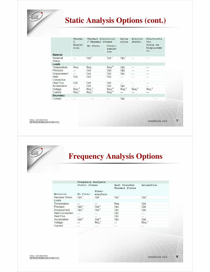
Static Analysis Options (cont.)
IntelliSuite v8.0 88
Frequency Analysis Options

IntelliSuite v8.0 99
Dynamic Analysis Options
IntelliSuite v8.0 1010
Dynamic Analysis Options (cont.)

IntelliSuite v8.0 1111
MEMaterial Introduction
� It is a powerful, easy-to-use simulation tool for the mechanical,
electrical, and optical modeling of thin films deposited on silicon
substrates.
� The software presents data on the properties of materials in two- and
three dimensional graphs as well as in tables. Using a wealth of
experimental data from respected sources, the software applies
IntelliSense’s unique multi-dimensional estimation and optimization
routines to calculate material property values for any combination of
parameters.
� With MEMaterial, you can
� simulate material behavior prior to fabrication
� add proprietary data
� get values of the property of interest for any combination of parameters
� Find maxima/minima
� View graphically the fabrication dependence of material properties
� Determine the nearest experimental points
IntelliSuite v8.0 1212
To open a material file
� File … Open Select one material with
property and technology by
Category or File Name
Double Click to Select

IntelliSuite v8.0 1313
Single Value Procedure
Click the value number to change to the desired
number and press Enter key
IntelliSuite v8.0 1414
2D & 3D Graph Procedures
1. Select Type of View
� View … 2D Graph or 3D Graph
Ctrl + Click to select
two parameters
(4. Update Values)2.
3.

IntelliSuite v8.0 1515
2D Graphic
� The red diamonds are all of the experimental points available for that data
combination. They are in the third dimension according to a variety of the
other parameters so they will not necessarily line up with the 2D graph.
IntelliSuite v8.0 1616
3D Graphic
Click and
Drag to
Rotate

IntelliSuite v8.0 1717
Experimental Points and References
Scroll
down
IntelliSuite v8.0 1818
AnisE: Anisotropic Etching Simulator
Top mask file:
Name.simt.msk
Bottom mask
Name.simb.msk
Note: When using
Layout…Import… to
import mask, the file
name will be the same
the imported file.
Layout figures must
be on first quadrant
IntelliSuite v8.0 1919
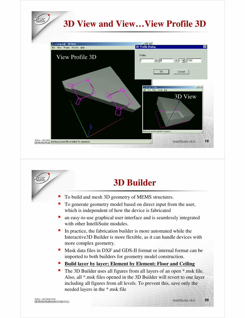
3D View and View…View Profile 3D
View Profile 3D
3D View
IntelliSuite v8.0 2020
3D Builder
� To build and mesh 3D geometry of MEMS structures.
� To generate geometry model based on direct input from the user,
which is independent of how the device is fabricated
� an easy-to-use graphical user interface and is seamlessly integrated
with other IntelliSuite modules.
� In practice, the fabrication builder is more automated while the
Interactive3D Builder is more flexible, as it can handle devices with
more complex geometry.
� Mask data files in DXF and GDS-II format or internal format can be
imported to both builders for geometry model construction.
� Build layer by layer; Element by Element; Floor and Ceiling
� The 3D Builder uses all figures from all layers of an open *.msk file.
Also, all *.msk files opened in the 3D Builder will revert to one layer
including all figures from all levels. To prevent this, save only the
needed layers in the *.msk file

IntelliSuite v8.0 2121
Building Concept
Partition horizontal and
vertical levels and entities
Entities: May be treated as
Materials
Building Procedure:
1. Select the level and entity
2. Draw the 4 node elements
(Grid pt, Element pt, Mask
pt or Keyboard)
IntelliSuite v8.0 2222
Geometry (Mesh) Manipulation
This allows for the rotation and
translation of the selected elements.
This allows you to
specify the relative
angle between two
areas of the structure.
IntelliSuite v8.0 2323
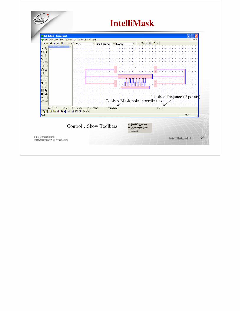
IntelliMask
Control…Show Toolbars
Tools > Mask point coordinatesTools > Distance (2 points)