
IMS Overview
164
IMS Overview LZT 123 8314 R1A © Ericsson AB, 2006 - 1 - IMS Overview STUDENT BOOK LZT 123 8314 R1A
Transcript of IMS Overview

IMS Overview
LZT 123 8314 R1A © Ericsson AB, 2006 - 1 -
IMS Overview
STUDENT BOOK LZT 123 8314 R1A

IMS Overview
- 2 - © Ericsson AB, 2006 LZT 123 8314 R1A
DISCLAIMER This book is a training document and contains simplifications. Therefore, it must not be considered as a specification of the system. The contents of this document are subject to revision without notice due to ongoing progress in methodology, design and manufacturing. Ericsson assumes no legal responsibility for any error or damage resulting from the usage of this document. This document is not intended to replace the technical documentation that was shipped with your system. Always refer to that technical documentation during operation and maintenance.
© Ericsson AB, 2006 This document was produced by Ericsson. • It is used for training purposes only and may not be copied or
reproduced in any manner without the express written consent of Ericsson.
This Student Book, LZT 123 8314, R1A supports course number LZU 108 6563 .
Table of Contents
LZT 123 8314 R1A © Ericsson AB, 2006 - 3 -
Table of Contents
IMS OVERVIEW.....................................................................................1
1 INTRODUCTION............................................................................7
INTRODUCTION....................................................................................9
NEW NETWORK TOPOLGY ...............................................................10
IP MULTIMEDIA SUBSYSTEM (IMS) ..................................................10
OPERATOR AND END-USER BENEFITS...........................................12
IMS PRODUCT POSITIONING............................................................13
ERICSSON IMS SOLUTIONS .............................................................14
2 IMS SERVICES ...........................................................................17
IMS PUSH TO TALK............................................................................19
IMS PUSH TO TALK SESSIONS.........................................................20 1-1 POC SESSION .........................................................................................20 AD-HOC POC GROUP SESSION ..................................................................21 PRE-ARRANGED POC GROUP SESSION ...................................................21 CHAT POC GROUP SESSION ......................................................................21
IMS WESHARE SESSIONS ................................................................22 IMS WESHARE IMAGE ..................................................................................22 IMS WESHARE MOTION ...............................................................................22 IMS WESHARE MEDIA FILE..........................................................................23 IMS WESHARE WHITEBOARD .....................................................................24
IMS MULTIMEDIA TELEPHONY (IMT) SERVICES.............................25 RESIDENTIAL SERVICES .............................................................................26 ENTERPRISE SERVICES ..............................................................................26 OPERATOR SERVICES.................................................................................27 IMT SERVICES...............................................................................................27
IMT END USER INTERFACES ............................................................32 SIP PHONE.....................................................................................................32 INTEGRATED ACCESS DEVICE (IAD) .........................................................32 SIP CLIENTS ..................................................................................................33

IMS Overview
- 4 - © Ericsson AB, 2006 LZT 123 8314 R1A
PC-CLIENT - ACTIVE CONTACTS ................................................................33 WEB-CLIENT - COMMPILOT .........................................................................39
3 IMS ARCHITECTURE .................................................................49
IMS COMMON SYSTEM......................................................................51
IMS SUBSYSTEMS .............................................................................53 IMS CORE ......................................................................................................53 IMS GATEWAYS ............................................................................................55 IMS ENABLERS..............................................................................................58 IMS APPLICATION SUBSYSTEMS ...............................................................59 MANAGEMENT AND SUPPORT FUNCTIONS FOR IMT..............................64
INTERFACES AND PROTOCOLS.......................................................68 PHYSICAL INTERFACES...............................................................................68 BASIC INTERNET PROTOCOLS...................................................................68 SIGNALING INTERFACES.............................................................................68 MEDIA INTERFACES .....................................................................................69
PLATFORMS .......................................................................................70
QUALITY OF SERVICE MECHANISMS..............................................72 DIFFSERV ......................................................................................................72
IMS SOLUTIONS .................................................................................74 IMS PUSH TO TALK.......................................................................................75 IMS WESHARE...............................................................................................76 IMS STUDIO ...................................................................................................76 IMS MULTIMEDIA TELEPHONY....................................................................77
4 MULTIMEDIA SESSION ESTABLISHMENT ..............................79
INTRODUCTION..................................................................................81 ADDRESS TYPES IN IMT ..............................................................................81 SESSION INITIATION PROTOCOL (SIP) ......................................................82
SIGNALING SEQUENCES ..................................................................84 REGISTRATION .............................................................................................84 DNS/ENUM QUERY FOR IMT .......................................................................88 BASIC SIP TO SIP SESSION FOR IMT .........................................................90 BASIC SIP TO PSTN SESSION FOR IMT .....................................................92

Table of Contents
LZT 123 8314 R1A © Ericsson AB, 2006 - 5 -
PRESENCE FOR IMT.....................................................................................95 INSTANT MESSAGE FOR IMT ......................................................................97 SET UP OUTGOING CALL FOR IMT.............................................................98 1-1 POC SESSION SCENARIO ...................................................................102
5 OPERATION AND MAINTENANCE..........................................105
INTRODUCTION................................................................................107
MN-OSS .............................................................................................108 CONFIGURATION MANAGEMENT .............................................................108 PERFORMANCE MANAGEMENT ...............................................................108 SECURITY MANAGEMENT .........................................................................108 FAULT MANAGEMENT ................................................................................109 SUPPORTED IMT NODES...........................................................................109 MN-OSS HARDWARE..................................................................................110 THE MN-OSS DESKTOP .............................................................................111 MN-OSS LIBRARY .......................................................................................113
ERICSSON FAULT MANAGER.........................................................114 ALARM HANDLING ......................................................................................114 LINK SUPERVISION.....................................................................................116
THE ALARM STATUS MATRIX (ASM) ..............................................118
THE ALARM LIST VIEWER (ALV) ....................................................119
GNIP AND ALARM STATUS VIEWER ..............................................121
THE ALARM LOG BROWSER (ALB) ...............................................124
AXD OPERATION SUITE ..................................................................127 BASE.............................................................................................................127 PERFORMANCE MONITOR ........................................................................128
ANALYZER (OPTIONAL) ..................................................................130
PROVISIONING FOR IMT .................................................................134 ROLES..........................................................................................................135 PROVISIONING ENTITIES...........................................................................137 CLASSIC PROVISIONING ...........................................................................140 SELF PROVISIONING..................................................................................142

IMS Overview
- 6 - © Ericsson AB, 2006 LZT 123 8314 R1A
PROVISIONING FOR MOBILE IMS ..................................................144
6 GLOSSARY...............................................................................147

1 Introduction
LZT 123 8314 R1A © Ericsson AB, 2006 - 7 -
1 Introduction

IMS Overview
- 8 - © Ericsson AB, 2006 LZT 123 8314 R1A
Intentionally Blank

1 Introduction
LZT 123 8314 R1A © Ericsson AB, 2006 - 9 -
INTRODUCTION Communication between people involves more senses than just voice. Ericsson believes that we will gradually migrate our preferences from classical telephony services towards richer means of communication. New ways of communicating are created by advanced user terminals, Internet related technologies and re-structured telecommunication networks. We are entering a new communications paradigm where video conferencing, presence, and messaging become part of our everyday life.
The Internet has shown in recent years that when a network is opened up for the purposes of application development, many new applications are created and are easily accessible by end-users. IP end-to-end is a requirement for this.
It is expected that Multimedia communications will gradually take over from telephony as the mainstream way of communicating as it provides a richer communication experience.
Multimedia is a combination of two or more media elements in relation to each other and synchronized in time and/or context, e.g. text, animations, and videos.
A multimedia session is an association between two or more parties for the exchange of real-time multimedia.
An end-user is a person subscribing to the services offered by a multimedia system.

IMS Overview
- 10 - © Ericsson AB, 2006 LZT 123 8314 R1A
NEW NETWORK TOPOLGY In order to fulfill market demands, a network topology change is needed and is happening now.
The topology is moving from a vertical to a horizontal layered architecture with a common IP-based connectivity network for all accesses, mobile, fixed, and data. See Figure 1-2.
This architecture will make it easier to deploy new services regardless of access and the common connectivity network will reduce the operation and bit transport cost.
Figure 1-1 New Network Topology.
IP MULTIMEDIA SUBSYSTEM (IMS) Ericsson IMS is developed with a core offering for both wireless and wireline operators and is a cornerstone for providing converged multimedia services across multiple accesses.
It consists of a common core, enablers, support systems and interworking functions enabling operators and service providers to leverage on installed legacy networks, thus reducing cost, while providing key end-user benefits like reliability and security.
1 Introduction
LZT 123 8314 R1A © Ericsson AB, 2006 - 11 -
Ericsson IMS is compliant with the WCDMA and CDMA 2000 standards architectures as defined in the 3rd Generation Partnership Projects (3GPP and 3GPP2) specifications for IP Multimedia. It is also based on IETF specifications, such as the Session Initiation Protocol (SIP) which uses the packet switched domain to transport multimedia signaling to and from the end-user terminal. It is also compliant with specifications from OMA and TISPAN.
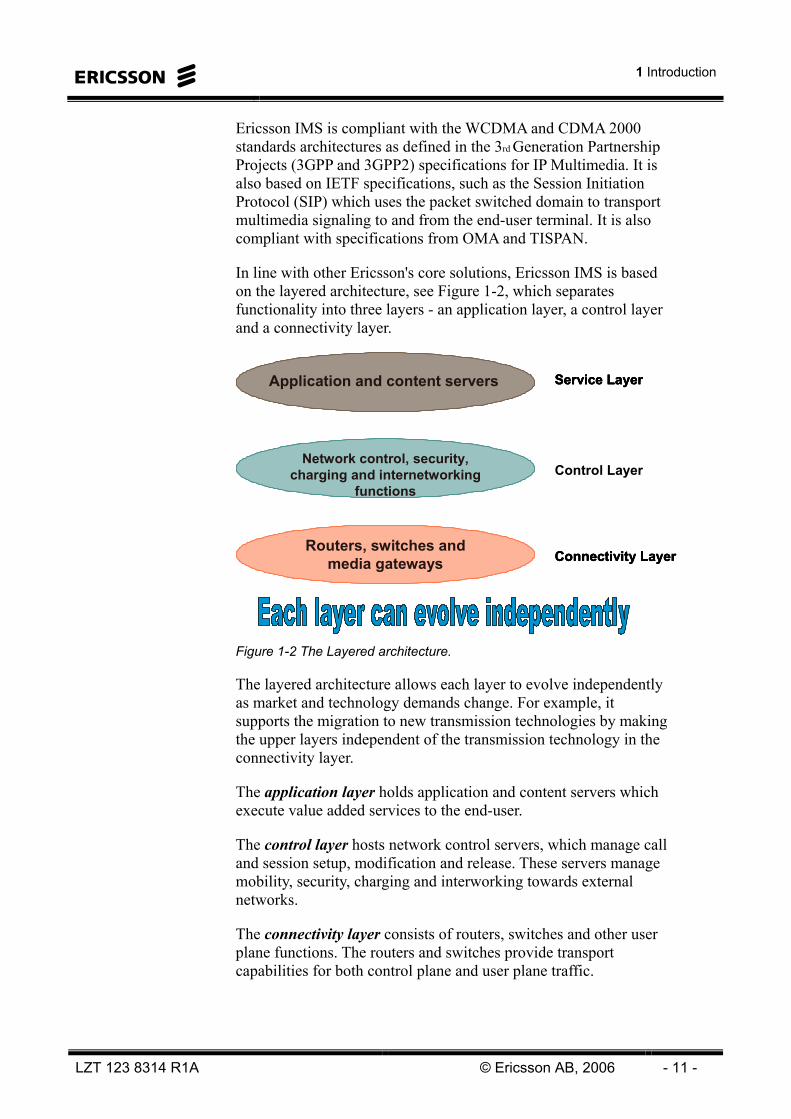
In line with other Ericsson's core solutions, Ericsson IMS is based on the layered architecture, see Figure 1-2, which separates functionality into three layers - an application layer, a control layer and a connectivity layer.
Network control, security,charging and internetworking
functions Control Layer
Routers, switches and media gateways Connectivity Layer
Service LayerApplication and content servers
Network control, security,charging and internetworking
functions Control Layer
Network control, security,charging and internetworking
functions Control Layer
Routers, switches and media gateways Connectivity Layer
Routers, switches and media gateways Connectivity Layer
Service LayerApplication and content servers Service LayerApplication and content servers
Figure 1-2 The Layered architecture.
The layered architecture allows each layer to evolve independently as market and technology demands change. For example, it supports the migration to new transmission technologies by making the upper layers independent of the transmission technology in the connectivity layer.
The application layer holds application and content servers which execute value added services to the end-user.
The control layer hosts network control servers, which manage call and session setup, modification and release. These servers manage mobility, security, charging and interworking towards external networks.
The connectivity layer consists of routers, switches and other user plane functions. The routers and switches provide transport capabilities for both control plane and user plane traffic.

IMS Overview
- 12 - © Ericsson AB, 2006 LZT 123 8314 R1A
OPERATOR AND END-USER BENEFITS IMS is an internationally recognized standard specifying interoperability, roaming, bearer control, charging and security. This makes IMS a key enabler for fixed-mobile network convergence.
IMS enabled convergence occurs in three distinct ways;
Convergence between fixed and mobile service environments. IMS enables end-to-end services, independent of access type. The architecture simplifies and speeds up the service creation and provisioning processes.
Convergence of vertical solutions towards a single common horizontal implementation. The horizontal architecture of IMS enables operators to move away from vertical ‘stovepipe’ implementations of new services – eliminating the costly and complex traditional network structure of overlapping functionality for charging, group and list management, routing and provisioning.
Convergence between traditional legacy circuit switched services and IMS enabled packet based services. For fixed and mobile operators there are benefits of introducing the IMS architecture today. In the longer term, IMS enables a secure migration path to an all-IP architecture that will meet end-user demands for new enriched services.
For the end-user, IMS-based services enable person-to-person and person-to-content communications in a variety of modes – including voice, text, pictures and video, or any combination of these – in a highly personalized and controlled way.

1 Introduction
LZT 123 8314 R1A © Ericsson AB, 2006 - 13 -
IMS PRODUCT POSITIONING The major step in network architecture evolution in the coming years is the introduction of IMS, see Figure 1-3. Introduction of Multimedia services over IP is one of the main drivers for this.
The evolution will be driven according to the following: • Similar evolution paths in fixed and mobile networks with
layered architecture.
• Common Multimedia control based on the 3GPP IMS architecture.
• All accesses connecting to a common IP core.
Figure 1-3 Ericsson target network architecture.
With a common IP core, the MSC Server controls wireless circuit switched traffic, the Telephony Server (TeS) to controls wireline circuit switched traffic, and the SIP server controls the multimedia traffic.

IMS Overview
- 14 - © Ericsson AB, 2006 LZT 123 8314 R1A
ERICSSON IMS SOLUTIONS Ericsson provides one solution for wireline (IMT) and two for wireless networks (Push to Talk (PTT) & WeShare), see Figure 1-4
Ericsson IMS Multimedia Telephony IP Centrex, VoIP, Presence, Video and Instant Messaging
Ericsson IMS WeShare Combinational services combining the CS and PS domain, to send images and files during a CS call.
Ericsson IMS Push to Talk Mobile “always-on” service
Ericsson IMS Common SystemBased on the IMS Standard specified by 3GPP
IMT PTT
WeShare
IMS Common System
Service Development StudioFor service development by 3rd
party.
SDS
Figure 1-4 The Ericsson IMS solutions.

1 Introduction
LZT 123 8314 R1A © Ericsson AB, 2006 - 15 -
Intentionally Blank

IMS Overview
- 16 - © Ericsson AB, 2006 LZT 123 8314 R1A
Intentionally Blank

2 IMS Services
LZT 123 8314 R1A © Ericsson AB, 2006 - 17 -
2 IMS Services

IMS Overview
- 18 - © Ericsson AB, 2006 LZT 123 8314 R1A
Intentionally Blank

2 IMS Services
LZT 123 8314 R1A © Ericsson AB, 2006 - 19 -
IMS PUSH TO TALK Push to Talk (PTT) provides easy, one touch communication to one or many mobile users. • Quick one way communication that is suitable for short
interactions.
• One to one voice calls
• One to many and group voice calls
• There is no need for pre-scheduling or using existing groups
A Global standard is vital for an interoperable mass-market service • A standard is now under development: OMA PoC
• Enables connection with anyone using PoC
Figure 2-1 Push To Talk.
The solution consists of the Ericsson IMS Common System and the IMS Push to Talk Application and any OMA PoC compliant terminal client. The Ericsson IMS Push To Talk solution is designed to work with all terminal clients following the OMA PoC specification.
Ericsson IMS Push to Talk is a Voice-over-IP (VoIP) application that offers easy-to-use half-duplex Push To Talk voice communication. The main benefit over regular voice communication is that users can communicate both one-on-one and in one-to-many fashion.

IMS Overview
- 20 - © Ericsson AB, 2006 LZT 123 8314 R1A
This allows for new exciting ways for people to communicate that create a number of new business opportunities for mobile operators. Ericsson also provides the needed infrastructure and services to encompass an end-to-end implementation.
IMS PUSH TO TALK SESSIONS The Group and Data Management function is an IMS enabler that can be used by multiple services. It provides the capability to manage user-specific information for different types of services. Most applications need this type of data.
The Group and Data Management feature in the Presence, Group and Data Manager (PGM) server enables a user to define and administer lists such as contact lists and group member lists from the User Equipment (UE) or from the Web User Data Manager (UDM). It also provides the ability to define groups and incoming call settings. These settings are used by the PoC Server (Call Screening Server specifically) during session initiation. (See chapter on IMS Architecture for more information about PGM.)
1-1 POC SESSION
This session scenario offers the ability for user A to have a Push to talk over Cellular (PoC) communication with user B. User A simply selects user B on a contact list (associated with a user identity in the form of a SIP URI or TEL URI) or gives the E.164 number and presses the PoC talk button to trigger the session establishment.
B has the ability to define whether incoming PoC sessions from the inviting user are to be rejected or granted by the network, by using the Access Policy and/or Incoming Session Barring functionality. During session set-up, the identity or display name of user A can be presented to B.
If automatic answer is used, user B will receive an indication of the incoming PoC session and the terminal accepts the session without any action from the user. When manual answer mode is used, user B will be alerted of the incoming PoC session. B then has to choose whether to accept or reject the PoC session request.
The session signaling is accomplished by using SIP/SDP messages and the media is transported using RTP/RTCP. (See chapter on IMS Architecture for more information about the protocols used in IMS.)

2 IMS Services
LZT 123 8314 R1A © Ericsson AB, 2006 - 21 -
AD-HOC POC GROUP SESSION
This session scenario offers the ability for user A to have an instant group communication with multiple B subscribers by simply selecting the invited users on a contact list, and pressing the PoC button to trigger the establishment.
User A is able to add other users to the ongoing session and will receive a notification of the result of the invitation per invited B user.
PRE-ARRANGED POC GROUP SESSION
A pre-arranged PoC group is a group with a member list, which has been defined prior to session initiation using the Group and List Management functionality in the network. Only a member of the group can establish or be part of such a group session.
CHAT POC GROUP SESSION
A Chat PoC Group is a group with or without a predefined member list. In case of a restricted chat group, only a member of the group can establish or be part of a Chat PoC Group Session.

IMS Overview
- 22 - © Ericsson AB, 2006 LZT 123 8314 R1A
IMS WESHARE SESSIONS Ericsson provides four basic IMS weShare session scenarios in order for a user to share resources and experiences during a CS call • IMS weShare Image
• IMS weShare Motion
• IMS weShare Media File
• IMS weShare Whiteboard.
IMS WESHARE IMAGE
IMS weShare Image allows users to share pictures during a CS call. Both the A- and B-party are able to send and receive pictures. The pictures are taken during the voice call and it is only possible to send one picture at a time i.e. the first picture has to be transferred before the second picture can be sent, see Figure 2-2.
Voice
Image
My vacation is great, you should see the beach
Yea, the water looks lovely
IMS Network
Figure 2-2 IMS weShare Image.
The whole picture is downloaded before it is displayed on the terminal. The downloading state is indicated on the terminal display. The picture is temporarily stored in a directory on the terminal and the receiving user may then store the image permanently.
IMS WESHARE MOTION
IMS weShare Motion allows users to share live video during a Circuit Switched (CS) call. Both the A- and B-party are able to send and receive video. Depending on what was negotiated during session setup, A- and B- send video simultaneously, or one at a time.

2 IMS Services
LZT 123 8314 R1A © Ericsson AB, 2006 - 23 -
Voice
Video
Party A Party B
Voice
Video
Party A Party B Figure 2-3 weShare.
Both the A- and B-user can trigger the feature regardless of who started the voice call. The receiver is able to accept or reject the video session. Further, the receiver can at any point close down the video session without closing down the IMS weShare application.
There is no synchronization between the video and the voice. The video contains no voice, as the voice content is sent via the CS connection. The video is played on the receiver’s terminal with an adapted delay so that it is possible to speak about it at the same time. Voice delay is about 200 ms and video delay between 600 and 2000 ms. Thus, there is approximately 400-1800 ms delay between voice and video.
The live video is not stored in any directory on the terminals.
IMS WESHARE MEDIA FILE
IMS weShare Media File allows users to share any stored image or video clip during a CS call. Both the A- and B-party are able to send and receive media and the shared media is already stored in the terminal. It is only possible for one user to send one media at a time i.e. the first media has to be completely transferred before a second transfer can begin, see Figure 2-4.

IMS Overview
- 24 - © Ericsson AB, 2006 LZT 123 8314 R1A
Voice
Media file
I like it, more!!!
Look at this video clip from the consert
IMS Network
Figure 2-4 IMS weShare Media File.
The Media File types supported are limited to stored images (JPEG and GIF) and stored video clips (3gp or MPEG4).
IMS WESHARE WHITEBOARD
The IMS weShare Whiteboard feature allows users to share a whiteboard session during a CS session. The users can draw on a blank background of configurable color, or select to share an image as the background for drawing, i.e. a map or a floor plan of a building. Both users can edit the drawing, and both users get to see the complete content. The involved users can individually store the session content at any time.
Figure 2-5 weShare Whiteboard.

2 IMS Services
LZT 123 8314 R1A © Ericsson AB, 2006 - 25 -
IMS MULTIMEDIA TELEPHONY (IMT) SERVICES IMT provides a wide range of fixed telephony services for residential and enterprise (business) users as well as services more directed to service providers. See Figure 2-6.
Personal ServicesMessagingMultimedia
The above and Group Services
Regulatory Services
IMT
Figure 2-6 IMS Multimedia Telephony (IMT) services.
An end-user typically has an analogue telephone used together with an Integrated Access Device (IAD), or a SIP telephone, to access the services offered by the IMT system. The end-user can also access the services by using the provided PC-based client - Active Contacts, or the Web-client – Commpilot Call Manager, which are intended to enhance the end-user experience, making it easier for the end-user to configure and use the multimedia services.
End-users are divided into two main categories: • Residential users
• Enterprise users
The residential user is usually a private individual that subscribes to the services by entering into a contract with an operator or other service provider.
The enterprise user is an employee of a company, who uses the services as a part of their job. In this case the company enters into a contract with the operator or other service provider for the whole company to use the services.

IMS Overview
- 26 - © Ericsson AB, 2006 LZT 123 8314 R1A
RESIDENTIAL SERVICES
The residential package offers three sub-packages.
Within the Personal services an end-user will have access to traditional PSTN features such as call forwarding and call waiting. In addition, the end-user will have a personal web portal where these services can be managed. This enables access to service settings via the Internet.
In the Messaging package there are services such as voice mailbox and message waiting indication. The end-user can also choose to have the voice mails sent to his/hers mailbox.
In the Multimedia services package the end-user gets access to services such as video telephony, presence and instant messaging.
ENTERPRISE SERVICES
The enterprise user has the same services as the residential user plus access to a number of Group services.
The group services are used by the IT administrator in the enterprise. The Group web portal, for example allows the administrator to manage the subscribers within the business group. The administrator can easily, via the web interface add new subscribers, change users service subscriptions etc.
Another feature is the Attendant console, which allows a receptionist to monitor the users within a business group. The console graphically displays users’ status, i.e. busy, idle and do not disturb, as well as detailed call information.
Within the category Other services there are features such as: • Remote office – where an end-user gets access to all his
communication services from any Internet enabled location.
• Outlook integration – allowing the CommPilot Call manager to be integrated into the address book of Outlook. With the benefit that the end-user can use the contact list in Outlook to initiate calls.

2 IMS Services
LZT 123 8314 R1A © Ericsson AB, 2006 - 27 -
OPERATOR SERVICES
In the category operator services there are Regulatory services such as Legal Intercept and number portability: • Local Number Portability – IMT leverages on the existing
infrastructure and routes originating calls to a ported number to a Transit Exchange in the PSTN that will determine whether a query to an LNP SCP is required. LNP query for a terminating call will also be handled within the PSTN network. The same call scenario as for an originating call apply in case of both originating and terminating user is hosted in the IMT network.
• Emergency Call (Zones) - allows a service provider to configure (on a group basis) whether emergency calls are allowed for a user, when roaming outside of the group’s home zone or location.
• Call Trace – the call signaling information can be presented and used to trace malicious calls.
• Operator Initiated Call Barring - When a barred user or enterprise attempts to a make a call, the operator will route them to an announcement.
IMT SERVICES
IMT provides all of the traditional call functions, including:
Auto callback – allows users to monitor a busy party within the same group, and automatically establish a call when the busy party becomes idle. The service is authorized and provisioned as a subscriber service, and can be enabled and disabled by the subscriber.
Voice portal calling – enhances the CommPilot voice portal by allowing an authenticated user to originate calls. This feature is particularly useful for traveling users who already access the voice portal to retrieve voice messages and configure services.
Traveling users typically access the voice portal using a toll-free number and this feature allows them to originate calls that eventually are charged against their account. For similar reasons, this feature can be useful for an employee working at home who needs to make long distance or international calls on behalf of the company. Dialing in to the voice portal first allows the subsequent long distance call to be charged to the company instead of the user’s home line.
IMS Overview
- 28 - © Ericsson AB, 2006 LZT 123 8314 R1A
Multiple forward-to phone numbers – expands the call forward service so that there is one forward-to phone number per rule, thus allowing users to forward calls to different phone numbers based on the time of day, day of week, and caller identity.
Sequential ringing – allows a user to define a “find-me” list of phone numbers that are alerted sequentially upon receiving an incoming call that matches a set of criteria. While the service searches for the user, the calling party is provided with a greeting followed by periodic comfort announcements. The caller can also interrupt the search to leave a message by pressing a key.
Conferencing
IMT includes a complete web-enabled business conferencing solution. The conferencing service allows users to schedule, initiate, and manage conference calls with both internal and external parties. Subscribers can schedule and manage conferences by using a web based portal interface, accessible from any PC with a standard web browser.
Multiple conference types are supported including:
One-Time Conferences – users schedule an upcoming conference that occurs only once. Moderator and participant access codes expire immediately after the conference completes.
Re-occurring Conferences – users schedule regular conference events (daily, monthly and so on). Moderator and participant codes are valid only during the recurring-window of time that the conference is scheduled.
Reservation less Conferences – users establish moderator and participant codes that never expire. Users can gather for conference anytime of the day, any day of the week.
Ad-hoc Conferences – using dial-out features, a moderator can gather users into a conference by dialing their number directly from the conference bridge using either the web-based portal or the telephone interface.
A web-based moderator interface is used for real-time control and management of the conference in order to: • Upload presentation material to be shared during the
conference.
• Mute, hold, drop, and add new participants to the conference.
• Record the conference in progress and review it afterwards.

2 IMS Services
LZT 123 8314 R1A © Ericsson AB, 2006 - 29 -
Messaging
IMT supports enhanced messaging services and provides all of the features of a traditional voice messaging solution.
It also supports the following enhanced messaging services: • Instant Messaging
• Voice Message delivery to any specified e-mail account.
• Voice Message waiting notification delivered to the phone and to any specified mail or Short Message Service (SMS) account (for example, a cell phone)
Voice messages are stored on standard e-mail servers (POP3, IMAP4, Microsoft Exchange Server) as WAV audio files attached to e-mails.
Users can retrieve their e-mail messages from their main location, from a 3rd-party location or from any standard e-mail client. When retrieving e-mail messages from their location, users simply dial the Voice Portal phone number (or extension).
Messages received as e-mails can be manipulated like any other e-mail (stored, forwarded, replied to, and so on). Some enterprises prefer to keep copies of all voice mail messages received, for regulatory or security reasons and this can in an easy way be configured in IMT.
Call Center Support
The Call Center service builds on the basic Hunt Group service to provide a complete, business-ready application. Hence, call centers inherit all of the characteristics of the Hunt Group service and are also provided with call-handling features like queuing and music on hold.
IMT expands the capabilities of legacy call centers by delivering a remote agent solution, allowing call center agents to be geographically distributed. Calls can be attended from home, a branch office, or any other location served by IMT in a transparent fashion.
The Call Center functionality can be combined with other Call Handling Completion services such as forwarding to voice mail or call transfer services to ensure that all incoming calls are serviced expeditiously under any network condition and at anytime:

IMS Overview
- 30 - © Ericsson AB, 2006 LZT 123 8314 R1A
Auto Attendant
The Auto Attendant provides enterprises with a tool to field inbound calls and deliver them to the intended destination through interactions with the caller.
The Auto Attendant is reached by dialing an associated phone number or an extension. Once connected to the Auto Attendant, the caller is played a greeting that provides a menu of options to complete call routing.
The Auto Attendant uses the multi-location enterprise capabilities of the IMT solution to support geographically distributed groups.
Virtual Private Networks
IMT provides support for both voice and multimedia enabled Virtual Private Networks (VPN) and can support rich variety of different deployment scenarios where several branch offices and remote locations within a company can be tied together with one overlay private numbering plan, by using prefix dialing.
VPN enables interconnection of PBXs and IP Centrex groups, see Figure 2-7. The IMT users connected to the IP Centrex ‘ebg1’ and external PBXs are defined as a single VPN called ‘vbg1’. The figure shows two Application Servers, but this could be defined on one AS.
Figure 2-7 Virtual Private Network.
The VPN service can be divided into the following components:

2 IMS Services
LZT 123 8314 R1A © Ericsson AB, 2006 - 31 -
Private Numbering Plans – Allows a private numbering plan and extension dialing to be used between enterprise locations, regardless of the equipment used at the location. The numbering plan defines private numbers to internal users as well as to destinations located outside of the enterprise, such as customers, suppliers, and/or partners.
Prefix and Extension Dialing – allows existing extension dialing schemes to be reused. Variable length location codes are prefixed onto local extensions to allow dialing of users at other locations. Dial patterns can also be used to identify external destinations and to allow extension like dialing to users outside of the enterprise. An access code for different call destinations (e.g. branch offices) is used (e.g. dial '81' for internal calls to branch A, ‘82’ for internal calls to branch B and dial '0' for external calls).

IMS Overview
- 32 - © Ericsson AB, 2006 LZT 123 8314 R1A
IMT END USER INTERFACES
SIP PHONE
Users can connect to IMT Services using SIP phones. These are intelligent telephones which signal in SIP directly.
INTEGRATED ACCESS DEVICE (IAD)
‘Traditional’ Analogue telephones can connect to the IMT network via an IAD, which converts DTMF to SIP and converts the speech from analogue to digital signals. This would only provide telephony speech functionality for the user.
Figure 2-8 Examples of SIP Phones.
2 IMS Services
LZT 123 8314 R1A © Ericsson AB, 2006 - 33 -
SIP CLIENTS
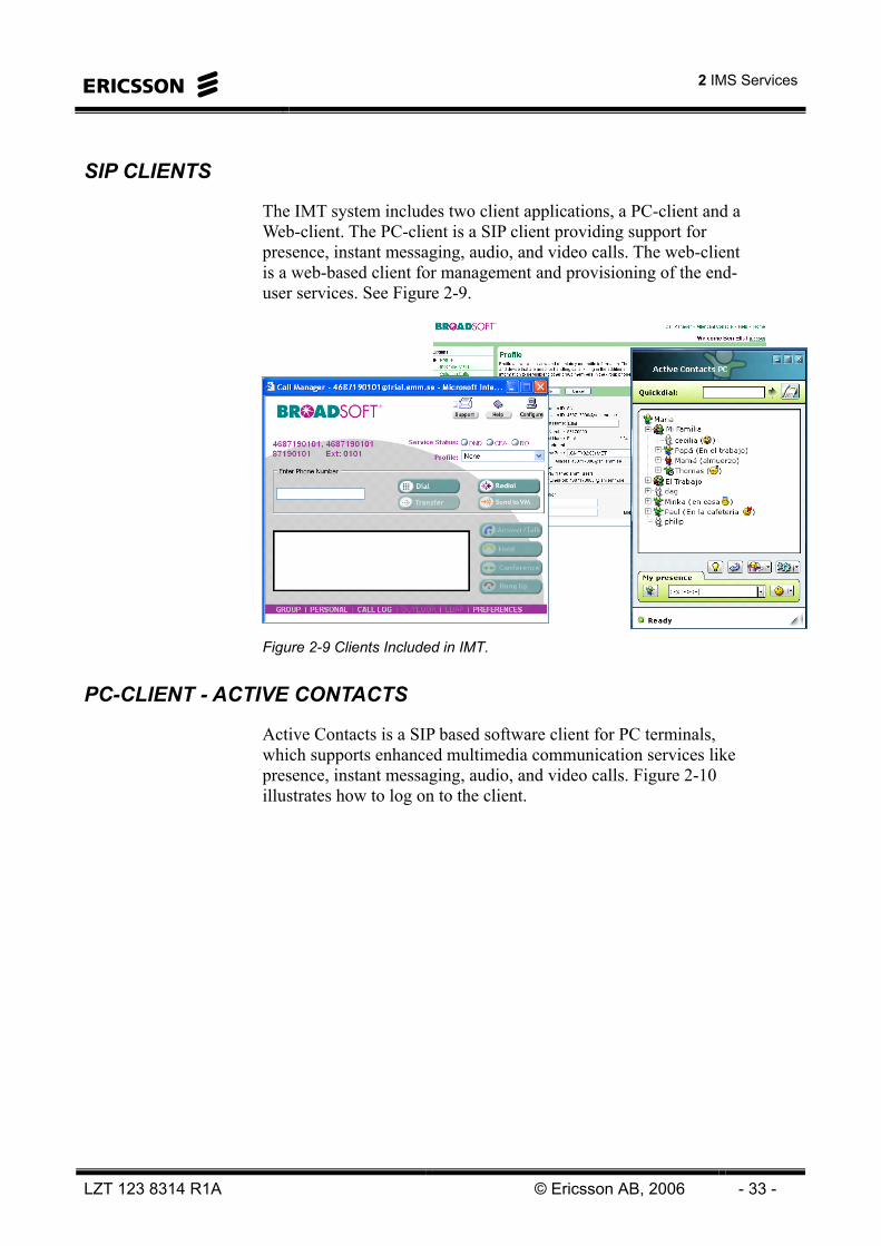
The IMT system includes two client applications, a PC-client and a Web-client. The PC-client is a SIP client providing support for presence, instant messaging, audio, and video calls. The web-client is a web-based client for management and provisioning of the end-user services. See Figure 2-9.
Figure 2-9 Clients Included in IMT.
PC-CLIENT - ACTIVE CONTACTS
Active Contacts is a SIP based software client for PC terminals, which supports enhanced multimedia communication services like presence, instant messaging, audio, and video calls. Figure 2-10 illustrates how to log on to the client.

IMS Overview
- 34 - © Ericsson AB, 2006 LZT 123 8314 R1A
Figure 2-10 Active Contacts, Select Account.
Active Contacts interacts with the CSCF using SIP. It includes the following functionality: • Online/Offline presence
• Set Presence Status – pre-configured available/busy/away states or free text presence.
• View Presence of contacts in the contact list. To see the Contact’s presence the Contact needs to have a SIP address for presence and subscribe to a presence service. However it is also valuable for users to have Contacts with just a PSTN number, as it is very simple to make IP to PSTN calls from the Contact List.
• Grouping of contacts in the contact list (presentation only). It is in the Contact List that the users see their Contacts’ presence and this is where they select whom to communicate with and how.
• Presence Policies – white/black list for presence watchers.
• Add/Drop Media – upgrade from an audio call to a video call, or the opposite, during the call.
• Call Hold/Resume.
• Instant Messaging with smileys or emoticons.
• Directory Search with filter on name, number, and Public ID.
• Call Logs – for all calls initiated or answered in the Active Contacts client.

2 IMS Services
LZT 123 8314 R1A © Ericsson AB, 2006 - 35 -
• Invoking services using feature access codes by sending DTMF tones during a call or including “*” and “#” as part of a dialed number.
Preferences are set as shown in Figure 2-11.
Figure 2-11 Active Contacts, Preferences, Proxy Settings.
From the dialog window of preferences, it is possible to set presence policy settings. See Figure 2-12.

IMS Overview
- 36 - © Ericsson AB, 2006 LZT 123 8314 R1A
Figure 2-12 Active Contacts, Presence Policy 1/2.
Communication Dialog Window
The Active Contacts Client has a Communication dialog window for messaging, voice and video calls.
The Communication dialog appears when a user is chatting or is in a call with another user. There can be several Communication dialogs open at the same time; one for each person the user is communicating with.
Figure 2-13 shows the pop-up message that appears when there is an unanswered incoming call.

2 IMS Services
LZT 123 8314 R1A © Ericsson AB, 2006 - 37 -
1
2
3
Figure 2-13 Active Contacts, Voice Call.
Call Management
The user of the Active Contacts client is always able to answer or decline an incoming call, independently of if they are already participating in a call. In addition the user can place an ongoing call on hold and make another call, using the hold/resume functionality.
Instant messages can be sent between users, during voice or video calls. Instant Messaging is only one-way communication. A user sends a message and does not get any notification that the message has arrived or if the receiver has read the message. In Figure 2-14 there is a notification pop-up for an incoming message. If there is no call or video session established, these messages are part of a chat.

IMS Overview
- 38 - © Ericsson AB, 2006 LZT 123 8314 R1A
12
3 4
Figure 2-14 Active Contacts, Voice Call and Instant Messaging.
The network doesn’t interfere with this service, the message is routed just like a basic session, via the different CSCF but no action is taken, just pure proxying.
User is authenticated and their authority to send instant messages is checked before the instant message is delivered. If authentication or authorization fails appropriate failure response is returned.
It is possible to add or remove voice and video to an ongoing dialog. See Figure 2-15.

2 IMS Services
LZT 123 8314 R1A © Ericsson AB, 2006 - 39 -
Figure 2-15 Active Contacts, Video Call and Instant Messaging.
WEB-CLIENT - COMMPILOT
The CommPilot is a web-based client for management and provisioning of the offered end-user services and it is launched by means of a Uniform Resource Locator (URL) pointing at the Web Server (CS-WS), in the CS subsystem.
The CommPilot™ Personal Web Portal provides the end-users with the following functionality: • View, configure, activate, and deactivate subscribed services.
• Offline service configuration, i.e. configuring of services when the end-user is not involved in a call.
• List of end-user services they are subscribed to.
• List of group services they are subscribed to.
• Context-sensitive help for every service.
• Feature access codes that are associated with subscribed-to services.
Customization can be done to for example the user profile, incoming calls, outgoing calls, and messaging.

IMS Overview
- 40 - © Ericsson AB, 2006 LZT 123 8314 R1A
Figure 2-16 shows the web-GUI for managing incoming calls.
Figure 2-16 CommPilot Personal Web Portal, Incoming Calls.
Call Forwarding Always
This service enables the user to redirect all incoming calls to another phone number. See Figure 2-17. Users have the option to activate and deactivate the service by dialing a feature code or configuring the service via the web interface. If activated, a user must specify the forwarding number. A status indicator identifies whether this service is enabled or not.
Figure 2-17 CommPilot Personal Web Portal, Incoming Calls, Call Forwarding Always.

2 IMS Services
LZT 123 8314 R1A © Ericsson AB, 2006 - 41 -
Simultaneous Ring – Personal
Simultaneous Ring enables users to have multiple phones ring simultaneously when any calls are received on their phone number. The first phone to be answered is connected. For example, calls to a user’s desk phone could also ring the user’s mobile phone.
Figure 2-18 illustrates the managing dialog for this.
Figure 2-18 CommPilot Personal Web Portal, Incoming Calls, Simultaneous Ring.
Greetings
Message Greetings allows the user to upload personal .WAV files as greetings to use when incoming calls reach the voice-messaging box.
Figure 2-19 shows the Greetings options.

IMS Overview
- 42 - © Ericsson AB, 2006 LZT 123 8314 R1A
Figure 2-19 CommPilot Personal Web Portal, Messaging, Greetings.
Voice Management
With voice management the user can specify how to handle voice messages. Unified messaging is used when the phone should retrieve voice messages. Another option is to have the messages sent to an e-mail address. See Figure 2-20.
Figure 2-20 CommPilot Personal Web Portal, Messaging, Voice Management.

2 IMS Services
LZT 123 8314 R1A © Ericsson AB, 2006 - 43 -
CommPilot Call Manager
The CommPilot client also enables real time management of calls and services through the CommPilot Call Manager. See Figure 2-21. The Call Manager is primarily for use together with a SIP telephone, analog telephone with IAD, or the PC-Client.
Figure 2-21 CommPilot Call Manager.
The following features are included with the Call Manager: • Click-to-Dial – enables user to input and dial a number, dial
directly from a drop-down Phone List (Personal, Group or Call Log) or Outlook tab, or click the Redial button.
• Call log - The user has access to a log of the last calls dialed, received, and missed, and can call them directly from the list. See Figure 2-22.
• Phone List, Group –This phone list enables users to dial any other member of their business group by selecting from a list of names on their Call Manager. See Figure 2-23. The list also serves as a searchable company directory, listing names, numbers and email addresses. Each user added to the group is automatically added to this list.
• Phone List, Personal – Enables users to dial frequently called numbers by selecting from a searchable list of names on their Call Manager. Each user can add, delete, edit, and re-order numbers in their list, which serves as a personal speed dial list.

IMS Overview
- 44 - © Ericsson AB, 2006 LZT 123 8314 R1A
• Answer Call – enables user who is already engaged in a call to answer another waiting call. When available, Calling Line ID is displayed with caller’s name and number.
• Call Hold/Retrieve – enables user to place an existing call on hold for an extended period of time, and then retrieve the call to resume conversation. While the calling party is held, the user may choose to make a consultation call to another party.
• Call Transfer – enables user to redirect a ringing, active, or held call to another number or directly to voice mail. Before transferring the caller, the user may choose to consult with the third party first or establish a three-way consultation.
• Conference – enables user to establish a three-way call involving two other parties.
• Release Call – enables user to disconnect a call that has been answered.
• Preferences – Allows the user to configure the Call Manager.
Figure 2-22 CommPilot Call Manager, Call Log.

2 IMS Services
LZT 123 8314 R1A © Ericsson AB, 2006 - 45 -
Figure 2-23 CommPilot Call Manager, Group.
The Call Manager includes buttons that enable the user to turn on/off frequently used services such as Call Forwarding Always and Do Not Disturb. Alternatively, if Express Call Manager has been configured, the user may change their Express Call Manager status (e.g. Available, Busy, Unavailable) by choosing from a drop-down list.
The Call Manager supports Outlook Integration and makes use of Microsoft Outlook to provide the user with: • Contacts - Access to the user’s contact database for directories
and dialing.
• Journaling – The user can have incoming and/or outgoing calls logged into the Outlook journal with their start time, answer time, and stop time. See Figure 2-24.
• vCard – Users can bring up the vCard of other parties involved in calls (when available) and create new vCards for parties who do not have one already.

IMS Overview
- 46 - © Ericsson AB, 2006 LZT 123 8314 R1A
Figure 2-24 CommPilot Call Manager, Journal Entry.
The integration with Outlook is transparent to the user. It does not require any configuration changes to Outlook. It is supported for Outlook 2000 and later versions.

2 IMS Services
LZT 123 8314 R1A © Ericsson AB, 2006 - 47 -
Intentionally Blank

IMS Overview
- 48 - © Ericsson AB, 2006 LZT 123 8314 R1A
Intentionally Blank

3 IMS Architecture
LZT 123 8314 R1A © Ericsson AB, 2006 - 49 -
3 IMS Architecture

IMS Overview
- 50 - © Ericsson AB, 2006 LZT 123 8314 R1A
Intentionally Blank
3 IMS Architecture
LZT 123 8314 R1A © Ericsson AB, 2006 - 51 -
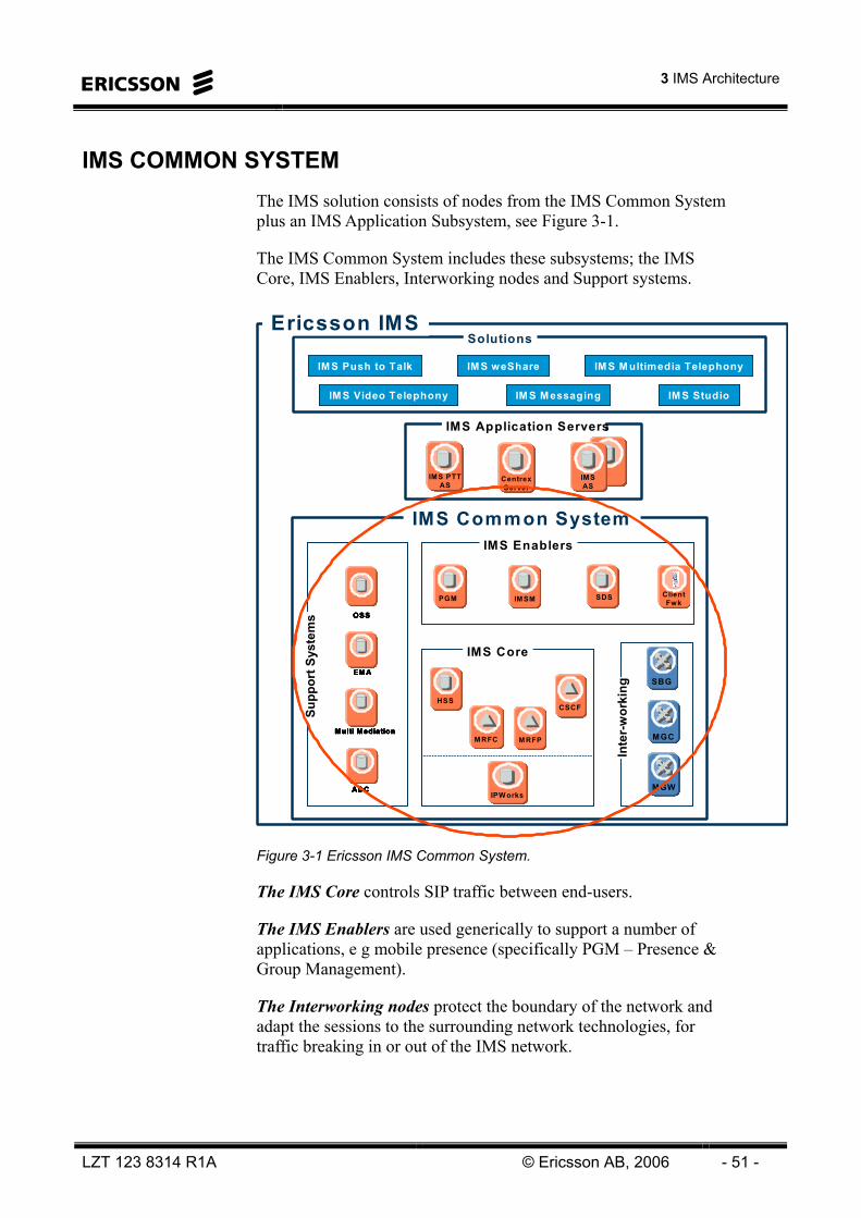
IMS COMMON SYSTEM The IMS solution consists of nodes from the IMS Common System plus an IMS Application Subsystem, see Figure 3-1.
The IMS Common System includes these subsystems; the IMS Core, IMS Enablers, Interworking nodes and Support systems.
Ericsson IMS
MGCMGC
SBG
MGWMGW
MRFCMRFC
CSCFCSCFCSCF
MRFPMRFP
PGMPGM IMSMIMSM SDSSDS
IMS Enablers
IMS Core
Inte
r-w
orki
ng
IMS PTTAS
CentrexServer
IMSAS
IMS Common System
IMS Application Nodes
IMS PTTAS
IMS PTTAS
CentrexServer
CentrexServer
IMSASIMSAS
IMS Common System
IMS Application Servers
Solutions
IM S Push to Talk IM S weShare
IM S Video Telephony IM S Studio
EMAEMA
Multi MediationMulti Mediation
ADC ADC
OSSOSS
IPW orks
Supp
ort S
yste
ms
IM S M ultimedia Telephony
IM S Messaging
ClientFwk
PGMHSS
Ericsson IMS
MGCMGC
SBG
MGWMGW
MRFCMRFC
CSCFCSCFCSCFCSCF
MRFPMRFP
PGMPGM IMSMIMSM SDSSDS
IMS Enablers
IMS Core
Inte
r-w
orki
ng
IMS PTTAS
CentrexServer
IMSAS
IMS Common System
IMS Application Nodes
IMS PTTAS
IMS PTTAS
CentrexServer
CentrexServer
IMSASIMSAS
IMS Common System
IMS Application Servers
Solutions
IM S Push to Talk IM S weShare
IM S Video Telephony IM S Studio
EMAEMA
Multi MediationMulti Mediation
ADC ADC
OSSOSS
IPW orks
Supp
ort S
yste
ms
IM S M ultimedia Telephony
IM S Messaging
ClientFwk
PGMHSS
Figure 3-1 Ericsson IMS Common System.
The IMS Core controls SIP traffic between end-users.
The IMS Enablers are used generically to support a number of applications, e g mobile presence (specifically PGM – Presence & Group Management).
The Interworking nodes protect the boundary of the network and adapt the sessions to the surrounding network technologies, for traffic breaking in or out of the IMS network.

IMS Overview
- 52 - © Ericsson AB, 2006 LZT 123 8314 R1A
The Support Systems are used for billing, provisioning, and O&M activities. They play a vital part in the operator control of the network.

3 IMS Architecture
LZT 123 8314 R1A © Ericsson AB, 2006 - 53 -
IMS SUBSYSTEMS The IMS solutions, as mentioned earlier, consist of several subsystems, see Figure 3-1.
IMS CORE
IMS Core includes functions for authentication and authorization of users, registration, and session handling. It also provides interfaces to the other subsystems as well as external systems.
The IMS Core subsystem consists of the following entities: • Call Session Control Server (CSCF)
• Home Subscriber Server (HSS)
DIAMETER
HSS S-CSCF
IMS CORE
I-CSCF
P-CSCF
SIP
SIP
• Authentication and Authorization of users• Registration• Session handling• Interfaces to the other subsystems• Interfaces to external systemsDIAMETER
HSS S-CSCF
IMS CORE
I-CSCF
P-CSCF
SIP
SIP
DIAMETER
HSS S-CSCFS-CSCF
IMS CORE
I-CSCFI-CSCF
P-CSCFP-CSCF
SIP
SIP
• Authentication and Authorization of users• Registration• Session handling• Interfaces to the other subsystems• Interfaces to external systems
Figure 3-2 IMS Core
Call Session Control Function
The CSCF is the main node in the IMS core and responsible for handling all multimedia sessions, using SIP as the call signaling protocol.
It is configured to assume three different roles in the network. These functions can be flexibly distributed, either co-located on common host(s) or distributed on separate hosts:
• Proxy Call Session Control Function (P-CSCF)
• Interrogating Call Session Control Function (I-CSCF)
• Serving Call Session Control Function (S-CSCF)

IMS Overview
- 54 - © Ericsson AB, 2006 LZT 123 8314 R1A
P-CSCF
The P-CSCF is the first contact point for the User Equipment. The P-CSCF behaves as a proxy and performs the following main tasks: • Forwards SIP messages from the UE to the SIP server in the
home network (and vice versa).
• Keeps track of registrations and active call sessions.
• Stores the UA IP address and port.
I-CSCF
The I-CSCF is the entry point for all connections destined to a subscriber in the home network. The I-CSCF, in cooperation with the HSS, assigns an S-CSCF during initial registration and routes the terminating session signaling to the allocated S-CSCF.
S-CSCF
The S-CSCF performs session control services for the UE including: • Subscriber registration by acting as a SIP Registrar.
• Downloading the HSS user profile with service trigger data.
• Notification of the application servers in order to provide multimedia services.
• Routing of SIP requests to other IMS servers (e.g. MGC for PSTN breakout calls).
• Querying the ENUM DNS for translation of E.164 numbers into routable SIP addresses and domain names into IP addresses.
• Outputting accounting data.
The CSCF interfaces to the Multi-Mediation (MM) for sending Charge Data Output (CDO); the ENUM DNS for address resolution purposes; and the MN-OSS for surveillance and configuration.
CSCF is deployed on the Ericsson Telecom Server Platform (TSP).

3 IMS Architecture
LZT 123 8314 R1A © Ericsson AB, 2006 - 55 -
Home Subscriber Server
The Home Subscriber Server (HSS) is an evolution of the Home Location Register (HLR), the Authentication Center (AUC), and the Authentication/Authorization/Accounting function (for Code Division Multiple Access (CDMA)). It is the master database that contains all user and subscriber information, and keeps track of which S-CSCF that the subscriber is registered to.
The HSS provides the following capabilities: • Identification of users.
• Security information generation.
• Keeps track of which S-CSCF the user is registered to.
• Service information in the user profiles, e g service triggers and application server identities.
The HSS interfaces the CSCF using the DIAMETER protocol, RFC 3588.
The HSS function is implemented on the TSP platform.
IMS GATEWAYS
The IMS Gateways consists of gateways for inter-working with external networks, see Figure 3-3.
Figure 3-3 IMS Gateways
IMS GATEWAYS
TDM
H.248
CSCFMGC
PSTN
N-SBG
MGWH.323
SIP
ISUP
VoIP
PC-CLIENT
WEB-CLIENT
A-SBG
SIP
SIP
SIP
SIP
MGC
IMS GATEWAYS
TDM
H.248
CSCFCSCFMGC
PSTNPSTN
N-SBGN-SBG
MGWMGWH.323
SIP
ISUP
VoIPVoIP
PC-CLIENT
WEB-CLIENT
PC-CLIENT
WEB-CLIENT
A-SBGA-SBG
SIP
SIP
SIP
SIP
MGC

IMS Overview
- 56 - © Ericsson AB, 2006 LZT 123 8314 R1A
Media Gateway Controller
The Media Gateway Controller (MGC) is a master to the Media Gateways. It is responsible for call control signaling (ISUP) to and from the PSTN and controls the MGW resources that handle the actual media streams, see Figure 3-4.
Figure 3-4 IMT – PSTN Interworking.
The Media Gateway Controller has the following capabilities: • Handles multimedia session establishment, modification, and
termination by using the SIP protocol in the IMS network and appropriate ISUP protocol in the PSTN domain.
• Supports addressing and routing of multimedia sessions to and from CSCFs and interconnected PSTN nodes.
• Controls one or more MGWs using the H.248 protocol.
• Performs mapping of application level signaling (SIP/ISUP).
The MGC is implemented on a SUN server.
Media Gateway
The MGW is responsible for handling the media payload to/from the PSTN network. All PSTN payload circuits terminate on a Media Gateway device and it is the gateway job to adapt these TDM circuits into IP packets, suitable for transportation over the IP network. The MGW also provides echo cancellation.
The MGW implemented on the AXD 301 platform.
MGW
MGCCSCF
IP
A-SBG
TDMSwitch
TDMSwitchIP TDMSIP
SIP ISUP
H.248
TDM
SignalingSpeech
IMT PSTN
TDMSwitch
MGW
MGCCSCF
IPIP
A-SBG
TDMSwitch
TDMSwitchIP TDMSIP
SIP ISUP
H.248
TDM
SignalingSpeech
IMT PSTN
TDMSwitch

3 IMS Architecture
LZT 123 8314 R1A © Ericsson AB, 2006 - 57 -
Session Boarder Gateway
The SBG is situated at the borders between IP networks, where it funnels sessions - signaling together with associated media streams of real time IP voice, video, and other data. The SBG uses IP signaling protocols such as H.323 and SIP, see Figure 3-5.
Figure 3-5 IMT – VoIP Interworking.
The aim of the SBG is to manage IP sessions across the IP network borders in order to ensure Security, Quality of Service (QoS), Service Level Agreements (SLAs), Network Address Translation (NAT), or firewall traversal, and other critical functions for IP streams.
The SBG has two roles in the IMS network: • As an Access Session Boarder Gateway (A-SBG) in the
crossing between an access network and the system, to funnel sessions from user agent clients (UAC) to the CSCF.
• As a Network Session Boarder Gateway (N-SBG) in the crossing between an external network and the system, to funnel sessions from external networks to the CSCF.
A network border in this context is the handoff point of any IP-enabled infrastructure, where a session passes from one network (or portion of the network) to another.
The SBG is configured to run as a SIP Back-to-Back User Agent (B2BUA), that is, SIP sessions are terminated and re-originated as new sessions. For each session, NAT translations are established and the Session Description Protocol (SDP) is re-written to force all session related media to be routed through the SBG.
Gatekeeper/SIP Server
N-SBGCSCF
IP
A-SBG
BGW ABGIP IPSIP
SIP SIP/H.323
SignalingSpeech
IMT VoIPGatekeeper/SIP Server
N-SBGCSCF
IPIP
A-SBG
BGW ABGIP IPSIP
SIP SIP/H.323
SignalingSpeech
IMT VoIP

IMS Overview
- 58 - © Ericsson AB, 2006 LZT 123 8314 R1A
IMS ENABLERS
Ericsson Presence and Group Management Server (PGM) is a common enabler, providing presence, group and data management functionality to different IMS applications. This makes the application development simpler and it minimizes the load on the mobile network.
The applications utilizing the PGM functionality can be either end-user terminal based (e g PoC Client) and/or server based (e g a web based presence interface or any HTTP application utilizing presence).
PGM provides the following main functions:
Presence Functionality - Publishing, storing and retrieving presence information. The presence server implements e g presence authorization rules.
Group & Data management - Group Management (or Data Management) is the capability to manage user specific service information for different types of services.

3 IMS Architecture
LZT 123 8314 R1A © Ericsson AB, 2006 - 59 -
IMS APPLICATION SUBSYSTEMS
The Application Subsystem for Mobile IMS contains the PoC Application Server and the weShare Application Server.
The Application Subsystems for IMS MultiMedia Telephony contains the Presence Server and the Centrex Servers.
POC Application server
The PoC AS, also known as the Ericsson Application Server is a dedicated server for the Ericsson IMS Push To Talk service. It includes the: • Call Screening Server (CSS),
• Media Resource Function (MRF).
Call Screening Server
The CSS can authorize a user to initiate a session by looking at the service settings of the invited users, as well as by providing the MRF with a group member list.
The CSS interacts with the MRF using VXML scripts over HTTP.
Media Resource Function
The Media Resource Function (MRF) contains functionality to allow manipulation of multimedia streams. It consists of a Media Resource Function Controller part (MRFC), located in the control layer, and a Media Resource Function Processor part (MRFP), located in the connectivity layer.
The MRFC is responsible for multi-party session control, connecting media resources to media streams. It controls the MRFP media distributor and changes its behavior based on information in session control messages from the CSS.
weShare Application Server
The IMS weShare application server is a dedicated server for the IMS weShare services. It includes the • IMS Application Server (IMS AS)
• WeShare-MRFP.

IMS Overview
- 60 - © Ericsson AB, 2006 LZT 123 8314 R1A
IMS Application Server
The IMS Application Server contains an internal MRFC function controlling a IMS weShare MRFP via a H.248 interface. In this way IMS AS can control the media plane and collect important statistics as well as information used for charging purposes.
WeShare-Media Resource Function Processor
The WS-MRFP provides relay mechanisms in order to transport Images, Media Files and Video to a particular destination by using MSRP (image and media file) and RTP (video) protocols. It also collects charging statistics.
Presence Server
The Presence Server has the following two primary features: • Storing presence information.
• Supporting subscription and notification of presence changes.
PS
PRESENCE SERVICES
PSPS
PRESENCE SERVICES
Figure 3-6 Presence Server for IMT
The end-user accesses the presence services at the Presence Server (PS) through the CSCF by using the PC-client ‘Active Contacts’.
User agents can publish and change presence information using the SIP PUBLISH method. Subscription and notification is accomplished using the SIP Event Notification method, using SUBSCRIBE to subscribe to presence, and NOTIFY to notify users of presence changes.
The end-user’s presence information is stored in the PS and includes the following information: • Presence status, e g available, busy, idle, or offline.
• A free-text presence message, e g “At home”, “In a meeting”, “Happy” to go with the presence status.
• UE information. For each UE device, the following information is available:
o Device address, for example, sip: [email protected].

3 IMS Architecture
LZT 123 8314 R1A © Ericsson AB, 2006 - 61 -
o Status, for example, available and idle.
o Timestamp, that is, time of last update.
o Description of the device, for example, “home PC”. • Watchers – a record of those people who have requested to
subscribe to the user’s presence information, and whether or not they are authorized to do so.
• Subscribers – the online subscribers to the user’s presence information. A Subscriber is currently logged on and will receive presence updates, whereas a Watcher perhaps currently is not online.
• Authorization policies – rules set by the users to determine who may subscribe to their presence information (whitelist/blacklist).
The core of the PS consists of a Java2™ Enterprise Edition (J2EE™) SIP engine deployed on a JBoss® Application Server.
Centrex Servers
The Centrex Services (CS) subsystem delivers communication services over packet networks, see Figure 3-7. The CS subsystem provides support for: • Call routing and translations.
• Media-oriented applications such as conferencing, voice mail, auto-attendant, and other Interactive Voice Response (IVR) applications.
• Personal calling functions such as selective call forwarding and notification, call transfer, and integration with Microsoft Outlook for contact retrieval and dialing.
CS-MS
CENTREX SERVICES
SIP
CS-DSCS-DS
CS-WSCS-WS
HTTP(S)
CS-ASCS-AS
HTTP(S)
CS-CSCS-CS
SIP
Figure 3-7 Centrex Servers for IMT
The Centrex Services subsystem consists of the following logical sub-entities: • Application Server

IMS Overview
- 62 - © Ericsson AB, 2006 LZT 123 8314 R1A
• Media Server
• Conference Server
• Web Server
• Distribution Server
All servers are part of the BroadWorks™ product suite.
Application Server
The Application Server (CS-AS) is the core entity of the CS subsystem and the main access point for control signaling.
The CS-AS is implemented as a Back-To-Back User Agent (B2BUA) to allow implementation of enhanced call control services. The CS-AS makes use of other servers to make a complete service solution.
Media Server
The Media Server (CS-MS) is responsible for specialized media resources including: • Digit detection.
• Announcement playback and recording.
• Media mixing functions such as 3-party call conferencing.
The CS-MS interfaces with the CS-AS for instructions and terminates the RTP media streams for detecting digits, recording audio, playing audio and mixing streams. These resources are used for services such as voice messaging, auto attendants, conferencing, etc.
The CS-MS does not have its own database, since all subscriber and service information is in the CS-AS database.
The CS-MS supports the following interfaces: • SIP for the communication between the CS-AS and the CS-
MS.
• RTP – used to send and receive media to access and network devices. The CS-AS redirects a device’s media stream to a particular resource on a CS-MS. The CS-MS terminates the media stream and performs the requested operations on the media stream.

3 IMS Architecture
LZT 123 8314 R1A © Ericsson AB, 2006 - 63 -
• SMTP – used for e-mail dispatch. This is used for messaging services. The unified messaging service makes use of this protocol to dispatch messages to a user’s mailbox.
Conference Server
The Conference Server (CS-CS) uses the CS-AS’s database and therefore no extra provisioning is needed for this entity.
Features offered by the CS-CS include: • Audio and Web Conferencing.
• Scheduled, recurring, reservation-less, and ad-hoc calls.
• Web Collaboration.
• Share Microsoft PowerPoint, Excel, and Word files.
The CS-CS supports the following protocols: • SIP – used for the communication between the CS-CS and SIP
network elements including the CS-AS. The communication is performed through the CSCF.
• RTP – used to send and receive media to access devices and network devices.
CORBA (XML) - used for retrieving subscriber data to the CS-CS from the CS-AS in the CS subsystem.
Web Server
The Web Server (CS-WS) provides a web-interface towards the CS-AS for operator provisioning and end-user self-provisioning of the CS-AS services. It hosts the Commpilot serves and Call manager.
The CS-WS interfaces the FE, CS-DS and CS-AS using HTTP(S).
Distribution Server
At web-login, the CS-DS provides the address of the hosting CS-AS of a given user to the CS-WS.
The CS-DS interfaces the CS-WS using HTTP(S).

IMS Overview
- 64 - © Ericsson AB, 2006 LZT 123 8314 R1A
MANAGEMENT AND SUPPORT FUNCTIONS FOR IMT
Operation and Maintenance functions are included in the system in order to provide a complete end-to-end network solution. See Figure 3-8.
FE•Provides HTTP login and CS-WS/AS selection.•Password retrieval from the SRD.EMA•Provides one uniform interface, through which all databases can be accessed from the Customer Administration System (CAS).MM•All Charge Data Output (CDO) is sent to, or collected by the MM system for refinement and distribution to the external BSS as CDRs.MN-OSS
•Used for fault, configuration, and performance management of thesystem.ENUM DNS•DNS for resolving of domain names into IP-addresses. •ENUM for resolving phone numbers into SIP-addresses.SRD•Directory searches from the PC-client.•Supports EMA for provisioning.•Web-client password management.
Man
agem
ent &
Sup
port
Fun
ctio
ns
EMAEMA
MN-OSSMN-OSS
MMMM
ENUM DNSENUM DNS
SRDSRD
FEFE
Man
agem
ent &
Sup
port
Fun
ctio
ns
EMA
MN-OSS
MM
ENUM DNS
SRD
FE
Man
agem
ent &
Sup
port
Fun
ctio
ns
EMAEMA
MN-OSSMN-OSS
MMMM
ENUM DNSENUM DNS
SRDSRD
FEFE
Figure 3-8 Management & Support Functions for IMT.
Front-End
The Front-End (FE) is the first point of contact when the end-user logs on to the web server to manage service settings. It provides the following functions: • HTTP login and CS-WS/AS Selection.
• Password retrieval from the SRD.
The FE interacts with the SRD for password validation (the passwords are stored in the SRD), as well as CS-WS/AS selection. The FE also interacts with EMA for password change.
Ericsson Multi Activation
Ericsson Multi Activation (EMA) is used as the main provisioning system. All end-users and groups, (and the data that is required), are created, modified, and deleted through EMA.

3 IMS Architecture
LZT 123 8314 R1A © Ericsson AB, 2006 - 65 -
In order to create a subscription, a number of different databases need to be accessed. EMA hides this complexity and provides one uniform interface, the Customer Administration Interface (CAI), through which all databases can be accessed from the Customer Administration System (CAS).
EMA utilizes the following protocols to distribute the provisioning information to the sub-systems: • CORBA (XML) for storing data in the CS-AS.
• LDAP for storing data in the HSS and the SRD.
• RMI for storing data in the PS (Remote Method Invocation).
• CAI for storing data in the ENUM DNS.
Additional client protocols used for provisioning and reading subscriber data are: • HTTPS for self-provisioning from the Web-client.
• LDAP for directory queries from the PC-Client.
Multi Mediation
All Charge Data Output (CDO) is sent to, or collected by the Multi Mediation (MM) system for refinement and distribution to the external Business Support System (BSS) as Call Detail Records (CDR).
The Multi Mediation system uses the following protocols for collecting charging data from the nodes: • RADIUS, according to RFC 2866.
• SFTP for polling charging data from the CS-AS not supporting RADIUS.
Multi Service Network-Operations Support System
The Multi Service Network – Operations Supports System (MN-OSS) is used for fault, configuration, and performance management of the IMT system.
The MN-OSS is a client-server management system that integrates a number of applications to provide a view of the managed network, including: • Fault management support for receiving and presenting alarms.
• Configuration management support with the facility to launch node centric applications such as element managers from a central point.

IMS Overview
- 66 - © Ericsson AB, 2006 LZT 123 8314 R1A
• Performance management support for collection and presentation of performance data and statistics.
• Security management in terms of authentication and authorization to access defined operation and maintenance roles.
• Access to the centralized online document store; the Alex library.
The system supports the following interfaces for fault-, configuration (excluding subscriber and service provisioning) and performance management: • SNMPv1, according to RFC 1157, SNMPv2, according to
RFC1441, and SNMPv3, according to RFC 3411, used for fault and performance management.
• Telnet, according to RFC 854, used for, for example, CLI commands.
• SFTP for retrieving data from nodes in the system.
• HTTPS used for configuration management of nodes in the system.
Type of used protocols depends on supported functionality in the supervised nodes.
ENUM Domain Name System
Almost all nodes in the system use DNS for resolving of names into IP-addresses. The system also uses ENUM for resolving phone numbers into SIP-addresses. The ENUM DNS system may utilize an external ENUM DNS for address resolution.
The system relies on the following standards: • DNS, according to RFC 1035, for resolution of Fully Qualified
Domain Name (FQDN) into IP address and port.
• ENUM, according to RFC 2916, for resolution of E.164 numbers to the associated SIP addresses.
System Repository and Directory
Parts of the provisioning data that the PS and the CS-AS stores are also stored in the System Repository and Directory (SRD). The reason of this is that the data will be easily available for other nodes in the system.
The SRD is used for two main purposes:

3 IMS Architecture
LZT 123 8314 R1A © Ericsson AB, 2006 - 67 -
• Enable directory searches from the PC-client.
• To redirect web-client requests to the correct CS-AS. This is used if the CS is configured with more than one pair of CS-ASs.
The SRD supports directory searches “white pages” searches using LDAP from the PC-client. Searchable attributes in the SRD are: • First name
• Last name
• SIP addresses
• Phone numbers
The user can search all open groups or be restricted to his or her closed groups.
The SRD is implemented using the Sun™ ONE™ Directory Server and EMA’s provisioning interface is used to update the directory data.

IMS Overview
- 68 - © Ericsson AB, 2006 LZT 123 8314 R1A
INTERFACES AND PROTOCOLS
PHYSICAL INTERFACES
The system supports the following physical protocols: • Ethernet according to IEEE 802.3.
• E1 according to G.704.
BASIC INTERNET PROTOCOLS
The system supports the following basic Internet protocols: • IPv4 according to IETF STD 5.
• TCP according to IETF STD 7.
• UDP according to IETF STD 6.
• HTTP 1.1 according to RFC 2616.
SIGNALING INTERFACES
The system supports the following signaling protocols: • SIP according to RFC 3261, between SIP-nodes in the system
and external SIP networks
• H.323 defined by ITU-T, for interaction with H.323 networks
• ISUP according to Q.761-764, for basic voice interaction with PSTN.
• SIMPLE according to IETF drafts for SIP Instant Messaging and Presence Leveraging Extensions, between SIP nodes in the system
• DIAMETER according to RFC 3588, for interaction between the CSCF and the HSS
• H.248, between the MGC and the MGW
• SIP for control signaling between the CS-AS and the CS-MS in the CS subsystem
• CORBA (XML) for communication between the CS-CS and the CS-AS in the CS subsystem
• CCP and CAP for call control from the web client to the CS-AS in the CS subsystem
3 IMS Architecture
LZT 123 8314 R1A © Ericsson AB, 2006 - 69 -
MEDIA INTERFACES
The system supports RTP for media transportation. Note that media streams may use peer-to-peer communication or utilizes the services offered by the subsystems in the service layer (e.g. Conference Server). In other words they are not using the same route as the control signaling.
The system supports the following media protocols: • RTP, according to RFC 1889, for media transportation
internally and to/from external IP networks.
• MSRP for transmission of video clips, images, bitmap graphics and whiteboard commands.
• TDM for media transportation towards PSTN networks.
Additionally, the system support sending and receiving emails via the Centrex Services subsystem via the following protocols: • SMTP, used for sending emails.
• POP3/IMAP4, used for email reception and retrieval.
More information about interfaces and protocols is found in Appendix 1.

IMS Overview
- 70 - © Ericsson AB, 2006 LZT 123 8314 R1A
PLATFORMS Figure 3-9 shows the nodes, platforms, and operating systems for IMT.
Subsystem Node Platform Hardware Configuration
Operating System
IMS Core CSCF TSP 5.0/NSP 5.1 Micro, Mini, Midi Dicos/Linux HSS TSP 5.0/NSP 5.1 Micro, Mini, Midi Dicos/Linux
IMS Gateways MGW AXD 301 Rel 7.1 10G/20G Erlang/Solaris X & Vrtx
MGC including SS7 connectivity
Sun Netra 240 2x1.5GHz, 2GB, 2x73GB+ ISR Board SS7-PCI E1 PACK
Solaris 8 or higher
SC (SBG) Acme Packet Net-Net Session Director
3 GE + 2 FE VxWORKS
Services PS HP CC3310 2x2.4GHz, 2GB, 2x73GB, + 2xFE
Linux, AS 3 Redhat
CS-MS Sun Netra 240 2x1.5GHz, 2GB, 2x73GB, + 2xFE
Solaris 8 or higher
CS-AS Sun Netra 240 2x1.5GHz, 2GB, 2x73GB
Solaris 8 or higher
CS-DS Sun Netra 240 1x1.5GHz, 0.5GB, 1x73GB
Solaris 8 or higher
CS-WS Sun Netra 240 1x1.5GHz, 0.5GB, 1x73GB
Solaris 8 or higher
CS-CS HP CC3310 2x2.4GHz, 2GB, 2x73GB, +2xFE) + Disk Dot Hill SANnet II (4x73GB)
Linux, AS 3 Redhat
FE Sun Netra 240 1x1.28GHz, 0.5GB, 1x73GB
Solaris 9
User Agents Active Contacts – PC client
PC – Windows® 2000
CommPilot – web client
Web browser – Microsoft Internet Explorer 5 or higher
Maintenance and Support functions
MN-OSS Sun Netra 240 2xSun Netra 240 (2x1.5GHz, 4GB, 2x73GB) + Graphics Card + Sun StorEdge 3310 (5x73GB) + StorEdge DAT 72
Solaris 8 or higher
EMA Sun Fire V240 1x1.34 GHz, 2GB, 4x73GB, 1xDVD
Solaris 8 or higher
MM Sun Fire V440 4x1.28GHz, 8 GB, 4x73GB, 1xDVD + Disk StorEdge 3310 (5x73GB) + StorEdge DAT 72
Solaris 8 or higher
ENUM DNS Sun Netra 240 1x1.5GHz, 0.5GB, 1x73GB
Solaris 9
SRD Sun Fire V240 2x1.28GHz, 8 GB, 2x73GB + Disk internal (2x146 GB)
Solaris 9

3 IMS Architecture
LZT 123 8314 R1A © Ericsson AB, 2006 - 71 -
Other products Firewall NetScreen 500 2 GE + 2xFE + 2 I/F interconnecting the NS for redundancy
ScreenOS 5.0 or higher
Traffic/Media Switch L3
Summit 48si 48 FE + 2 GE Extremeware 7.1.0
O&M Switch L3 Summit 48si 48 FE + 2 GE Extremeware 7.1.0
Switch L3 Alpine 3804 Up to 4 modules with each 32FE, 4GE or 16GE
Extremeware 7.1.0
Figure 3-9 Mapping of Nodes to Platforms for IMT.
Figure 3-10 shows the nodes, platforms, and operating systems for Mobile IMS.
Subsystem Node Platform Hardware Configuration
Operating System
SBG
Integrated Site Framework
Services MRFC/MRFP TSP
PoC AS
WS MRFP
Dicos/Linux
WS AS
PGM
TSP
TSP
TSP
Dicos/Linux
Dicos/Linux
Dicos/Linux
IS Framework
EMA Classic Sun Fire V240 1x1.34 GHz, 2GB, 4x73GB, 1xDVD
Solaris 8 or higher
ENUM DNS Sun Netra 240 1x1.5GHz, 0.5GB, 1x73GB
Solaris 9
Sun Netra 240 Sun Netra 240 (2x1.5GHz, 4GB, 2x73GB) + Graphics Card + Sun StorEdge 3310 (5x73GB) + StorEdge DAT 72
Solaris 8 or higherMaintenance andSupport functions
MN-OSS
LI-IMS Sun Netra 240 1x1.5GHz, 0.5GB, 1x73GB
Solaris 9
IMS Gateways
Figure 3-10 Mapping of nodes to platforms for Mobile IMS.

IMS Overview
- 72 - © Ericsson AB, 2006 LZT 123 8314 R1A
QUALITY OF SERVICE MECHANISMS There are different demands on quality depending on type of service. Voice services, for example, require low delay. Other services might require low delay variation. There is a trade off between bandwidth and delay. For voice services bandwidth has to be increased to keep delays low.
Initially the UE does not know the media capability of the other UEs in the session. Therefore, all UEs report their media capability to the CSCF that keeps a record of the media parameters of all UEs that are registered. The media capability of a UE is reported either in the SIP session establishment or when performing a SIP Re-INVITE or a SIP UPDATE during a session.
In order to guarantee a certain level of quality, an initial agreement is made between all involved UEs and the CSCF about the media parameters that are to be used in the session, which basically means a negotiation to make all members of the session adapt to the common lowest denominator in terms of bandwidth usage.
DIFFSERV
Differentiated Services (Diffserv) is a service paradigm where traffic flows (packets) are marked (i.e. assigned priorities or classes of service) at the edge of the network and where the backbone/core IP network forwards the packets in accordance with this marking.
This enables differentiated treatment of packets, that is, the packets can be sent to queues with different priorities. 6 bits in the IP header ToS field are used, known as DiffServ Code Points (DSCP). See Figure 3-11.
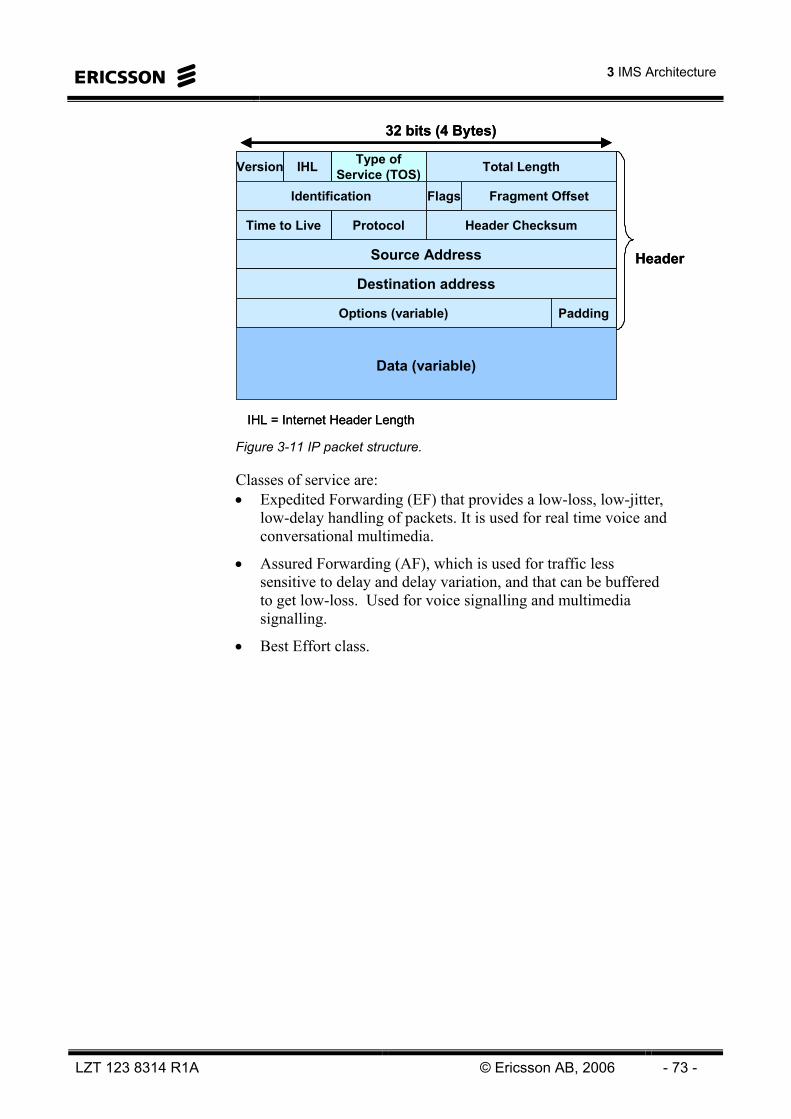
3 IMS Architecture
LZT 123 8314 R1A © Ericsson AB, 2006 - 73 -
32 bits (4 Bytes)
HeaderSource Address
Version Type ofService (TOS) Total LengthIHL
Identification Fragment Offset
ProtocolTime to Live Header Checksum
Destination address
PaddingOptions (variable)
Flags
Data (variable)
IHL = Internet Header Length
32 bits (4 Bytes)
HeaderSource Address
Version Type ofService (TOS) Total LengthIHL
Identification Fragment Offset
ProtocolTime to Live Header Checksum
Destination address
PaddingOptions (variable)
Flags
Data (variable)
IHL = Internet Header Length Figure 3-11 IP packet structure.
Classes of service are: • Expedited Forwarding (EF) that provides a low-loss, low-jitter,
low-delay handling of packets. It is used for real time voice and conversational multimedia.
• Assured Forwarding (AF), which is used for traffic less sensitive to delay and delay variation, and that can be buffered to get low-loss. Used for voice signalling and multimedia signalling.
• Best Effort class.

IMS Overview
- 74 - © Ericsson AB, 2006 LZT 123 8314 R1A
IMS SOLUTIONS The IMS Common System is used together with an IMS Application Subsystem to form an IMS Solution. There are currently four IMS Solutions available, indicated by ‘stars’ in Figure 3-12. • IMS Push to Talk
• IMS weShare
• IMS MultiMedia Telephony
• IMS Studio
Ericsson IMS
MGCMGC
SBG
MGWMGW
MRFCMRFC
CSCFCSCFCSCF
MRFPMRFP
PGMPGM IMSMIMSM SDSSDS
IMS Enablers
IMS Core
Inte
r-w
orki
ng
IMS PTTAS
CentrexServer
IMSAS
IMS Common System
IMS Application Nodes
IMS PTTAS
IMS PTTAS
CentrexServer
CentrexServer
IMSASIMSAS
IMS Common System
IMS Application Servers
Adv
ise,
Inte
grat
e an
d M
anag
e
Solutions
IMS Push to Talk IMS weShare
IMS Video Telephony IMS Studio
EMAEMA
Multi MediationMulti Mediation
ADC ADC
OSSOSS
IPWorks
Supp
ort S
yste
ms
IMS Multimedia Telephony
IMS Messaging
ClientFwk
PGMHSS
Ericsson IMS
MGCMGCMGCMGC
SBGSBG
MGWMGWMGWMGW
MRFCMRFCMRFCMRFC
CSCFCSCFCSCFCSCFCSCFCSCFCSCF
MRFPMRFPMRFPMRFP
PGMPGMPGMPGM IMSMIMSMIMSMIMSM SDSSDSSDSSDS
IMS Enablers
IMS Core
Inte
r-w
orki
ng
IMS PTTAS
IMS PTTAS
CentrexServer
CentrexServer
IMSASIMSAS
IMS Common System
IMS Application Nodes
IMS PTTAS
IMS PTTAS
CentrexServer
CentrexServer
IMSASIMSAS
IMS Common System
IMS Application Servers
Adv
ise,
Inte
grat
e an
d M
anag
e
Solutions
IMS Push to Talk IMS weShare
IMS Video Telephony IMS Studio
EMAEMAEMAEMA
Multi MediationMulti MediationMulti MediationMulti Mediation
ADC ADC ADC ADC
OSSOSSOSSOSS
IPWorksIPWorks
Supp
ort S
yste
ms
IMS Multimedia Telephony
IMS Messaging
ClientFwk
ClientFwk
PGMHSSPGMHSS
Figure 3-12 IMS Solutions.

3 IMS Architecture
LZT 123 8314 R1A © Ericsson AB, 2006 - 75 -
IMS PUSH TO TALK
The IMS Push to Talk solution is based on the Push to talk over Cellular (PoC) standard. It is an end-to-end solution offering mobile, half-duplex voice communication services that combine ‘always-on’ capabilities with ease of use.
It incorporates the following components, see Figure 3-13: • IMS Core: Call Session Control Function (CSCF), Home
Subscriber Server (HSS), Media Resource Function (MRF), Domain Name Server (DNS).
• IMS Enablers: Presence and Group Management (PGM)
• IMS Inter-working: Session Boarder Gateway (SBG)
• Support Systems: Operation Support System (OSS), Ericsson Multi Activation (EMA), Ericsson Multi Mediation (MM), Automatic Device Configuration (ADC)
• IMS Application server: PoC Application Server
MSCCS Voice
OPERATIONAL SUBSYSTEM
SERVICE NETWORK SUBSYSTEM
Ericsson Application Server
S-CSCF
MRFP
MRFC
I-CSCFP-CSCF
CCFand
OCF
HSS
IMS CORE NETWORK SUBSYSTEM
SIP SIP
Diameter
Diameter
RTP/RTCP
Sub Network Manager
SNMP/LDAP/FTP
SIP
NOTE! Some infrastructure (DNS, routers, access networks etc.) and interfaces are removed for simplicity
PoC Client
Provisioning Of Ericsson
Multimedia
LDAP/CLI
PoC AS
Presence and Group Management Server
Aggregation Proxy
XCAP
Web UDM
Internet
Call Screening Server
ISC
XCAP/HTTPS
weShare application logic
IMS AS
WS-MRFP
H.248
weShare AS
Diameter
INTERWORKINGSUBSYSTEM
N-SBG
MSRP/RTP
SIP
WS Client
LI-IMSServer
LI InterfaceSh
NODES
GG
SN
InternetInternet
Figure 3-13 IMS PTT and IMS weShare logical architecture.

IMS Overview
- 76 - © Ericsson AB, 2006 LZT 123 8314 R1A
IMS WESHARE
The IMS weShare solution is Ericsson’s implementation of the 3GPP combinational services specification (CSI). This solution introduces a concept of mobile services based on the simultaneous use of CS telephony and IMS service components in mobile networks.
The initial services offered are weShare Image, Motion, Media File and Whiteboard, supporting enrichments with picture, video clips and live video and providing graphical collaboration environment. Further enhancements will include music and games.
It incorporates the following components, see Figure 3-13: • IMS Core: CSCF, HSS, Media Resource Function Processor
(MRFP), DNS
• IMS Enablers: PGM
• IMS Inter-working: SBG
• Supporting Systems: OSS, EMA, MM
• IMS Application Server: WeShare-Application Server
• Clients: weShare Symbian client and EMP platforms with embedded weShare support.
IMS STUDIO
The IMS Studio Solution is Ericsson's offering for IMS service creation, service exploration, developer program.
The core of the solution is the Service Development Studio (SDS), a service creation tool that enables operators and third party developers to design their own IMS applications.
SDS supports creation of both the server and the client side of IMS applications, and contains high-level Application Program Interfaces (API) to hide network and terminal complexity for the designer. SDS contains five main components: • Design environment
• Service API’s
• Terminal emulation
• Test environment including IMS network simulation
• Trial execution environment.

3 IMS Architecture
LZT 123 8314 R1A © Ericsson AB, 2006 - 77 -
IMS MULTIMEDIA TELEPHONY
IMS MultiMedia Telephony (IMT) is an end-to-end network solution, enabling delivery of advanced multimedia services and content over fixed broadband networks, including IP Centrex and IP Telephony Services. The solution was previously named the Engine Multimedia (EMM) solution.
It provides a comprehensive service set to address the growing residential broadband market by combining an enhanced voice service offering with multimedia services like video telephony, presence and instant messaging.
The solution also includes a complete IP Centrex functionality addressing the SME and large enterprise market.
IMT will also support Cellular accesses in the future.
It incorporates the following components, see Figure 3-14: • IMS Core: CSCF, HSS, DNS
• IMS Inter-working: Media Gateway (MGW), Media Gateway Controller (MGC), SBG
• Supporting Systems: Front End server (FE), OSS, EMA, MM, System Repository and Directory (SRD)
• Application Servers: Presence, Application, Conference, Web, Distribution, and Media Servers.
IMS GATEWAYS
TDM
DIAMETER
H.248
HSS CSCFCSCFMGC
PSPS
Service Layer
Control Layer
Connectivity Layer
PSTNPSTN
N-SBGN-SBG
MGWMGW
SIP
SIP
H.323
SIP
ISUP
CS-MS
CENTREX SERVICES
PRESENCE SERVICES
IMS CORE
USER AGENTSSIP
VoIPVoIP
PC-CLIENT
WEB-CLIENT
PC-CLIENT
WEB-CLIENT
SIP
A-SBGA-SBG
SIP
SIP
SIP
SIP
Handles RTP Streams
Man
agem
ent &
Sup
port
Fun
ctio
ns
EMA
MN-OSS
MM
ENUM DNS
SRD
FE
Man
agem
ent &
Sup
port
Fun
ctio
ns
EMAEMA
MN-OSSMN-OSS
MMMM
ENUM DNSENUM DNS
SRDSRD
FEFECS-DSCS-DS
CS-WSCS-WS
MGC
HTTP(S)
CS-ASCS-AS
HTTP(S)
CS-CSCS-CS
SIP
Figure 3-14 IMS MultiMedia Telephony architecture.

IMS Overview
- 78 - © Ericsson AB, 2006 LZT 123 8314 R1A
Intentionally Blank

4 Multimedia Session Establishment
LZT 123 8314 R1A © Ericsson AB, 2006 - 79 -
4 Multimedia Session Establishment

IMS Overview
- 80 - © Ericsson AB, 2006 LZT 123 8314 R1A
Intentionally Blank

4 Multimedia Session Establishment
LZT 123 8314 R1A © Ericsson AB, 2006 - 81 -
INTRODUCTION This chapter shows examples of end-to-end signaling sequences. It is not intended to describe SIP or other protocols in detail, but to show the main IMS node functions and hoe they are involved in IMS call establishment and other flows.
ADDRESS TYPES IN IMT
Various addresses are used in ISP and IMS for different purposes. Some of the main ones are described below, as these are needed to understand the flows described in this chapter.
Address Type Example Usage
Private User Identity [email protected] Master identity, used for authentication/authorization, etc.
Public User Identity SIP:[email protected] The public SIP address that can be used for addressing of terminating SIP sessions towards the user.
Alias [email protected] Alternative public SIP address that can be used for addressing of terminating SIP sessions towards the user.
E.164 Number +46 8 123456 A public, international phone number associated with the user, which can be used for addressing of terminating SIP sessions towards the user.
Extension Number 3456 The user’s extension number within a group.
UA Address [email protected]:5060 IP address used to address the User Agent where currently registered (dynamic address).
Address TypeAddress Type ExampleExample UsageUsage
Private User IdentityPrivate User Identity [email protected]@domain.com Master identity, used for authentication/authorization, etc.Master identity, used for authentication/authorization, etc.
Public User IdentityPublic User Identity SIP:[email protected]:[email protected] The public SIP address that can be used for addressing of terminating SIP sessions towards the user.
The public SIP address that can be used for addressing of terminating SIP sessions towards the user.
AliasAlias [email protected]@domain.com Alternative public SIP address that can be used for addressing of terminating SIP sessions towards the user.
Alternative public SIP address that can be used for addressing of terminating SIP sessions towards the user.
E.164 NumberE.164 Number +46 8 123456+46 8 123456 A public, international phone number associated with the user, which can be used for addressing of terminating SIP sessions towards the user.
A public, international phone number associated with the user, which can be used for addressing of terminating SIP sessions towards the user.
Extension NumberExtension Number 34563456 The user’s extension number within a group. The user’s extension number within a group.
UA AddressUA Address [email protected]:[email protected]:5060 IP address used to address the User Agent where currently registered (dynamic address).
IP address used to address the User Agent where currently registered (dynamic address).
Figure 4-1 IMS address types.

IMS Overview
- 82 - © Ericsson AB, 2006 LZT 123 8314 R1A
SESSION INITIATION PROTOCOL (SIP)
The Session Initiation Protocol (SIP) is used to establish and control the multimedia sessions. This section describes the main SIP methods used in the IMS system. The SIP methods can be divided into Requests and Responses. The Responses are either provisional or final.
SIP MESSAGESSIP MESSAGES
REQUESTSREQUESTS RESPONSESRESPONSES
PROVISIONALPROVISIONAL FINALFINALINVITEREGISTERBYECANCELACKNOTIFYSUBSCRIBEPUBLISHMESSAGE
RFC 3261
OWN RFC’s
100-199100 Trying,180 Ringing, and 183 Session progress
>1992xx Success3xx Redirect4xx Client Mistake5xx Server Failure6xx Global Failure
Figure 4-2 SIP Messages.
REGISTER
The REGISTER method is used to create a binding between the user’s SIP address and the current UE contact address (IP address & port).
INVITE
The INVITE method is used to invite a remote user to a new SIP session. It can also be used to modify existing sessions, in which case it is referred to as a Re-INVITE.
ACK
The ACK method is used to acknowledge a final SIP response to an INVITE request.
BYE
The BYE method is used to terminate a SIP session.
4 Multimedia Session Establishment
LZT 123 8314 R1A © Ericsson AB, 2006 - 83 -
CANCEL
The CANCEL method is used to terminate an ongoing SIP session invitation.
MESSAGE
The MESSAGE method is used to send an instant message.
SUBSCRIBE
The SUBSCRIBE method is used to request presence information updates about a user.
PUBLISH
The PUBLISH method is used to send presence information about/from a user to the Presence Server.
NOTIFY
The NOTIFY method is used by the Presence Server to send presence information about a user to other users.

IMS Overview
- 84 - © Ericsson AB, 2006 LZT 123 8314 R1A
SIGNALING SEQUENCES This section outlines signaling sequences for some typical sessions.
REGISTRATION
A prerequisite for all end user services is that the user is registered in the home network S-CSCF. A user registers from a UE by sending a register request to the network, by means of a SIP REGISTER message.
The registrar function enables mobility by allowing the user to register at any terminal in the network. See Figure 4-3 to learn more about what information is stored where in the different nodes before, during, and after registration.
After RegistrationDuring RegistrationBefore RegistrationNode
Same as during registrationMay have presence state information
HSS addressUser service profileP-CSCF name/address P-CSCF network IDPublic user IDUE IP address
No presence state information
S-CSCF in Home network
User service profileS-CSCF name/address
User service profileP-CSCF network IDS-CSCF name/address
User service profileHSS in home Network
Same as before registration
S-CSCF name/addressP-CSCF network ID
HSS addressS-CSCF preferences
I-CSCF in home network
UE IP addressPublic user IDS-CSCF name/address
UE IP addressPublic user ID
-P-CSCF in local network
Same as before registration
Same as before registration
CredentialsHome domainProxy name/address
UE – In local Network
Figure 4-3 Information storage for IMT, before, during and after registration.

4 Multimedia Session Establishment
LZT 123 8314 R1A © Ericsson AB, 2006 - 85 -
1. REGISTER(URI=Home Registrar, To=Public-A, Contact=IP-A, Auth=Private-A)
3. USER AUTHORISATIONREQUEST
(Private-A, Public-A)
UE-A(SC-A) I-CSCF HSS-A S-CSCF-A
4. USER AUTHORISATIONANSWER
(required S-CSCF capabilities)
5. REGISTER(URI=S-CSCF, To=Public-A, Contact=IP-A, Auth=Private-A)
6. MULTIMEDIAAUTHENTICATION REQUEST
(Private-A, Public-A, S-CSCF URI)
7. MULTIMEDIAAUTHENTICATION ANSWER
(NOK, nonce)
8. 401 UNAUTHORISED (WWW-Auth = nonce)
10. 401 UNAUTHORISED(WWW-Auth = nonce)
11. REGISTER(URI=Home Registrar, To=Public-
A, Contact=IP-A,Auth= Private-A & nonce &
response)
13. USER AUTHORISATIONREQUEST
(Private-A, Public-A)
14. USER AUTHORISATIONANSWER
(S-CSCF URI)
15. REGISTER(URI=S-CSCF,To=Public-A, Contact=IP-A,
Auth=Private-A & nonce & response)
18. SERVER ASSIGNMENTREQUEST
(Private-A, Public-A, S-CSCF URI)
19. SERVER ASSIGNMENTANSWER
(User Profile)
20. 200 OK (WWW-Auth=nextnonce)
22. 200 OK(WWW-Auth=nextnonce)
P-CSCF
2. REGISTER(URI=Home Registrar,
To=Public-A, Contact=IP-A,Auth=Private-A)
9. 401 UNAUTHORISED(WWW-Auth = nonce)
12. REGISTER(URI=Home Registrar,
To=Public-A, Contact=IP-A,Auth=Private-A & nonce &
response)
21. 200 OK(WWW-Auth=nextnonce)
16. MULTIMEDIAAUTHENTICATION REQUEST
(Private-A, Public-A, S-CSCF URI,nonce, response)
17. MULTIMEDIAAUTHENTICATION ANSWER
(OK, nextnonce)
Figure 4-4 New Registration for IMT (successful).

IMS Overview
- 86 - © Ericsson AB, 2006 LZT 123 8314 R1A
1. The user-A initiates registration from the UE-A, whereby the UE-A sends SIP REGISTER towards the user's home domain registrar functionality (Request URI pre-configured in the UE). The REGISTER includes the user's public address to be registered as well as their private address and the IP address of the UE. The REGISTER is routed to a P-CSCF using a proxy address that is pre-configured in the UE.
2. The P-CSCF stores the UE-A contact (IP) address, before it adds a Path header to the REGISTER and proxies it to an I-CSCF based on the Request URI of the REGISTER. The Path header contains a P-CSCF-URI to inform the S-CSCF where to route terminating requests for the user.
3. The I-CSCF sends USER AUTHORISATION REQUEST (Diameter) containing the user's private and public address to the HSS.
4. The HSS returns the required S-CSCF capabilities to the I-CSCF.
5. Based on the received information, the I-CSCF selects the S-CSCF and forwards the REGISTER to the selected S-CSCF by inserting the S-CSCF address as new Request URI. The S-CSCF stores the contents of the REGISTER Path header (the P-CSCF address; to be used for routing terminated requests towards this public address) and the UE-A IP address (received in REGISTER Contact header).
6. The S-CSCF requests an Authentication Vector (AV) from the HSS to be used to challenge the user as part of the authentication procedure. The MULTIMEDIA AUTHENTICATION REQUEST contains the public and private user address, as well as the selected S-CSCF address.
7. The HSS stores the S-CSCF address and returns an AV (including “nonce” value) in the MULTIMEDIA AUTHENTICATION ANSWER (Diameter).
8-10. The S-CSCF invokes an Authentication Challenge by returning 401 UNAUTHORISED towards the UE-A. The WWW-Authenticate header of the message includes the “nonce”.
11. Based on the received information, the UE computes the “response” and returns this value as well as the “nonce” in a new REGISTER request sent to the P-CSCF.
12. The P-CSCF proxies the REGISTER to an I-CSCF.

4 Multimedia Session Establishment
LZT 123 8314 R1A © Ericsson AB, 2006 - 87 -
13. The I-CSCF sends USER AUTHORISATION REQUEST (Diameter) containing the user's private and public address to HSS.
14. The HSS returns the S-CSCF URI that was previously received from S-CSCF (6).
15. The REGISTER request is forwarded from the I-CSCF to the S-CSCF
16. The S-CSCF proxies the received authentication parameters in a new MULTIMEDIA AUTHENTICATION REQUEST towards the HSS.
17. The HSS checks that the received “nonce” and “response” values are correct, and returns a positive acknowledgement as well as a new “nonce” value (= “nextnonce”).
18. The S-CSCF informs the HSS that the user has been registered by sending a SERVER ASSIGNMENT REQUEST (Diameter) containing the public and private user address, as well as the selected S-CSCF address.
19. The HSS returns the User Profile including the CS-AS trigger filtering criteria and CS-AS address information, etc.
20-21. The S-CSCF sends a 200 OK response to the P-CSCF indicating that the registration was successful. The 200 OK contains the “nextnonce” (to be used for authentication of a subsequent SIP Request) that was received from the HSS (17), as well as a Service Route header containing the S-CSCF URI (to be used for routing of subsequent originating SIP requests from the P-CSCF to the S-CSCF).
22. The P-CSCF saves the value of the Service-Route header and associates it with UE-A. The P-CSCF then forwards the 200 OK response from the I-CSCF to the UE-A.
Notes: • All clients do not support the reception of “nextnonce” in 200
OK (17, 20-22).
• In conjunction with successful registration, the PC-Client also sends SUBSCRIBE towards all users (i.e. their Presence Servers) for which the user have requested presence information.
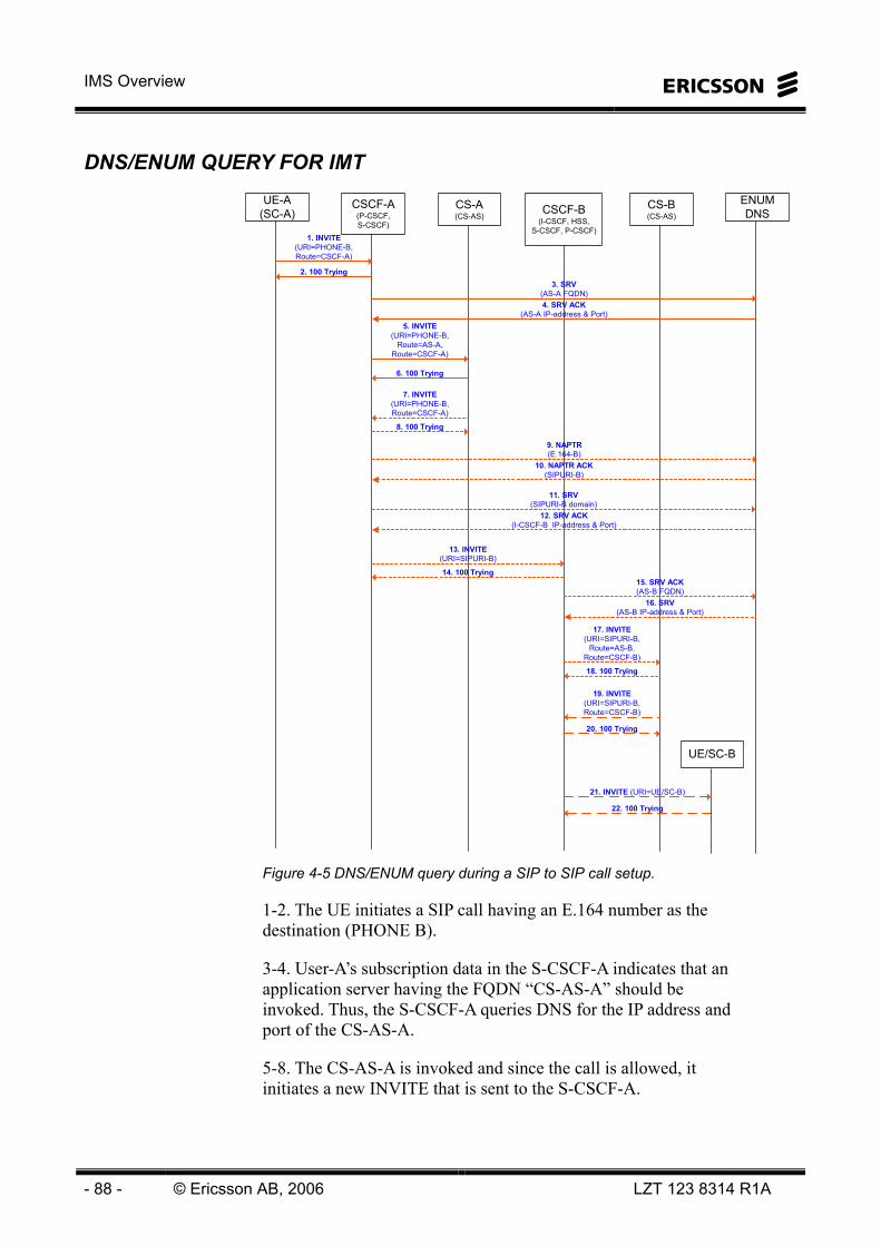
IMS Overview
- 88 - © Ericsson AB, 2006 LZT 123 8314 R1A
DNS/ENUM QUERY FOR IMT
21. INVITE (URI=UE/SC-B)
22. 100 Trying
UE-A(SC-A)
CSCF-A(P-CSCF,S-CSCF)
CS-A(CS-AS)
CSCF-B(I-CSCF, HSS,
S-CSCF, P-CSCF)
CS-B(CS-AS)
ENUMDNS
19. INVITE(URI=SIPURI-B,Route=CSCF-B)
20. 100 Trying
1. INVITE(URI=PHONE-B,Route=CSCF-A)
5. INVITE(URI=PHONE-B,
Route=AS-A,Route=CSCF-A)
7. INVITE(URI=PHONE-B,Route=CSCF-A)
13. INVITE(URI=SIPURI-B)
6. 100 Trying
14. 100 Trying
8. 100 Trying
2. 100 Trying3. SRV
(AS-A FQDN)4. SRV ACK
(AS-A IP-address & Port)
9. NAPTR(E.164-B)
10. NAPTR ACK(SIPURI-B)
11. SRV(SIPURI-B domain)
12. SRV ACK(I-CSCF-B IP-address & Port)
15. SRV ACK(AS-B FQDN)
16. SRV(AS-B IP-address & Port)
17. INVITE(URI=SIPURI-B,
Route=AS-B,Route=CSCF-B)
18. 100 Trying
UE/SC-B
Figure 4-5 DNS/ENUM query during a SIP to SIP call setup.
1-2. The UE initiates a SIP call having an E.164 number as the destination (PHONE B).
3-4. User-A’s subscription data in the S-CSCF-A indicates that an application server having the FQDN “CS-AS-A” should be invoked. Thus, the S-CSCF-A queries DNS for the IP address and port of the CS-AS-A.
5-8. The CS-AS-A is invoked and since the call is allowed, it initiates a new INVITE that is sent to the S-CSCF-A.

4 Multimedia Session Establishment
LZT 123 8314 R1A © Ericsson AB, 2006 - 89 -
9-10. The S-CSCF-A notices that the destination address (Request URI) contains an E.I64 number, whereby an ENUM query is made. Since the E.164 number is associated with an EMM2.0 subscription, ENUM returns the SIP URI of the B-subscriber.
11-12. The S-CSCF-A queries DNS in order to retrieve the FQDN and IP address & port of the I-CSCF-B to handle the session (the domain name of the SIP address is sent to DNS).
13-14. The S-CSCF-A proxies the INVITE to the I-CSCF-B, before the I-CSCF-B queries the HSS-B and forwards the message to the S-CSCF-B.
15-16. The user B’s subscription data in the S-CSCF-B indicates that an application server having the address “CS-AS-B URL” should be invoked. Thus, the S-CSCF-B queries DNS for the IP address and port of the CS-AS-B URL.
17-20. The CS-AS-B is invoked and the subscription data indicates that the session shall be set-up towards the UE-B having the SIP address “URI B”.
21-22. The S-CSCF-B forwards the INVITE (via the P-CSCF-B) to the UE-B using the IP address & port of the UE that were stored at UE-B registration.

IMS Overview
- 90 - © Ericsson AB, 2006 LZT 123 8314 R1A
BASIC SIP TO SIP SESSION FOR IMT
1. INVITE(URI=PHONE-B (short))
3. INVITE(URI=PHONE-B (short))
5. INVITE(URI=PHONE-B (full))
13. INVITE (URI=UE/SC-B)
4. 100 Trying
6. 100 Trying
15. 180 Ringing
17. 180 Ringing
21. 180 Ringing
29. ACK30. ACK
32. ACK
34. ACK
33. ACK
35. ACK
31. ACK
2. 100 Trying
14. 100 Trying
UE-A(SC-A)
CSCF-A(P-CSCF,S-CSCF)
CS-A(CS-AS)
CSCF-B(I-CSCF, HSS,
S-CSCF, P-CSCF)
CS-B(CS-AS)
UE-B(SC-B)
9. INVITE(URI=SIPURI-B)
11. INVITE(URI=SIPURI-B)
10. 100 Trying
12. 100 Trying
16. 180 Ringing
18. 180 Ringing
20. 180 Ringing
19. 180 Ringing 22. 200 OK
24. 200 OK
28. 200 OK
23. 200 OK
25. 200 OK
27. 200 OK
26. 200 OK
Both Way RTP Media
7. INVITE (URI=SIPURI-B)
8. 100 Trying
Figure 4-6 SIP to SIP.
1-2. The user A initiates a SIP-call towards B (PHONE) by dialing a private short number whereby the UE-A sends an INVITE message to CSCF-A (where A is registered).
3-4. Based on the subscription trigger data stored in CSCF-A (previously downloaded from HSS-A at registration), CSCF-A triggers AS-A.

4 Multimedia Session Establishment
LZT 123 8314 R1A © Ericsson AB, 2006 - 91 -
5-6. AS-A executes originating application logics using the subscriber's (end-user and/or company data) profile data. The call is allowed, which means that AS-A translates the dialed short number into a full E.164 number and returns the INVITE to CSCF-A.
7-8. CSCF-A queries ENUM for the SIP address associated with the E.164 number, before it forwards the INVITE to CSCF-B to which B has registered.
9-10. Based on the subscription trigger data stored in CSCF-B (previously downloaded from HSS-B at registration), CSCF-B triggers AS-B.
11-12. AS-B executes terminating application logics using the subscriber's (end-user and/or company data) profile data. The data indicates that B shall have the incoming call delivered to a registered SIP-client, whereby AS-B returns the INVITE to CSCF-B.
13-14. CSCF-B forwards the INVITE message to B's SIP client using the IP address and port that was earlier stored in CSCF-B at UE-B registration.
15-21. B's UE alerts the B-user and sends a Ringing message backwards to the UE-A via the CSCFs and ASs.
22-28. B accepts the call, whereby the 200 OK is sent backwards to UE-A via the CSCFs and AS's.
29-35. UE-A confirms the session establishment by sending ACK to UE-B before media streams are established between the two UEs.

IMS Overview
- 92 - © Ericsson AB, 2006 LZT 123 8314 R1A
BASIC SIP TO PSTN SESSION FOR IMT
1. INVITE(URI=PHONE-B,Auth=Private-A)
3. INVITE(URI=PHONE B,Auth=Private-A)
5. INVITE(URI=PHONE B,
P-AS-ID=E.164-A)
7. INVITE (URI=PHONE B, P-AS-ID=E.164-A)
4. 100 Trying
8. 100 Trying
6. 100 Trying
2. 100 Trying
UE-A(SC-A)
CSCF-A(P-CSCF,S-CSCF)
CS-A(CS-AS)
MGC-BMGW-B PSTN-B
9. IAM(CdPN=E.164-B,CngPN=E.164-A)
10. ACM
Both Way RTP Media
11. 183 Session Progress
16. 180 Ringing
Both Way TDM
20. ANM
29. REL
30. RLC
28. ACK
21. 200 OK
31. BYE
38. 200 (BYE)
15. CPG
12. 183 SessionProgress
13. 183 SessionProgress14. 183 Session
Progress
17. 180 Ringing
18. 180 Ringing
19. 180 Ringing
22. 200 OK
23. 200 OK
24. 200 OK
25. ACK
26. ACK
27. ACK
32. BYE
33. BYE
34. BYE
35. 200 (BYE)
36. 200 (BYE)
37. 200 (BYE)
Figure 4-7 SIP to PSTN (B-release).

4 Multimedia Session Establishment
LZT 123 8314 R1A © Ericsson AB, 2006 - 93 -
1-2. User-A initiates a SIP-call towards B (PHONE) whereby the UE-A sends an INVITE message to CSCF-A (where A is registered).
3-4. Based on the subscription trigger data stored in CSCF-A (previously downloaded from HSS-A at registration), CSCF-A triggers A's Application Server (AS-A).
5-6. AS-A executes originating application logics (such as outgoing call screening and short number translation) using the subscriber's (end-user and/or company data) profile data. The call is allowed, which means that AS-A returns the INVITE to CSCF-A after inserting A’s E.164 number in the P-Asserted-Identity header (5).
7-8. ENUM analysis (executed after number normalization) indicates that the destination is not associated with an EMM2.0 subscription, whereby CSCF-A forwards the INVITE message to MGC after querying an internal breakout table.
9. MGC maps the SIP INVITE into an ISUP Initial Address Message (IAM). The E.164 number in the P-Asserted-Identity header is mapped into ISUP Calling Party Address, while the E.I64 number in the SIP Request-URI is mapped into the Called Party Number field.
10-14. When MGC receives an ISUP Address Complete Message (without Alerting Indication) from the outgoing side, it maps it into a SIP 183 Session Progress message that is sent backwards to UE-A. Note: The ACM received from PSTN (10) may include an Alerting Indication, which means that CPG (15) is never received, but SIP 180 Ringing (16) is sent backwards already at reception of ISUP ACM. In this case, SIP 183 Session Progress (11-14) is never sent.
15-19. Upon receiving an ISUP Call Progress Message (CPG) containing an alerting indication, MGC sends a SIP 180 Ringing backwards. UE-A informs the user A by playing a ring-back tone locally.
20-24. As B answers the call, an ISUP Answer Message (ANM) is received by the MGC, which sends a SIP 200 OK backwards to UE-A.
25-28. UE-A sends the ACK-message to MGC via the CSCF and AS, before media streams are established between the UE and the B-party, with MGW handling the transcoding between the SIP and PSTN network.

IMS Overview
- 94 - © Ericsson AB, 2006 LZT 123 8314 R1A
29-30. As B hangs up, an ISUP Release message is sent to MGC, which immediately returns a Release Complete message and releases the seized resources on the outgoing side.
31-34. MGC informs UE-A about the B-Release by sending a SIP BYE message.
35-38. UE-A confirms the call release by returning a 200 (BYE). All seized resources are released.

4 Multimedia Session Establishment
LZT 123 8314 R1A © Ericsson AB, 2006 - 95 -
PRESENCE FOR IMT UE-A
(SC-A)CSCF-A
(P-CSCF,S-CSCF, I-CSCF)
PS-A PS-B UE-BCSCF-B(I-CSCF, HSS,
S-CSCF,S-CSCF-1)
1. SUBSCRIBE(URI=SIPURI-B,From=SIPURI-A)
8. NOTIFY(URI=SIPURI-A,From=SIPURI-B,
State info B)
9. NOTIFY(URI=SIPURI-A, From=SIPURI-B, State info B)
10. NOTIFY(URI=UE/SC-A,
From=SIPURI-B,State info B)
2. SUBSCRIBE (URI=SIPURI-B, From=SIPURI-A)3. SUBSCRIBE(URI=SIPURI-B,From=SIPURI-A)
7. B authorises therequest (proprietary)
4. 200 OK
5. 200 OK
6. 200 OK
11. 200 OK
12. 200 OK
13. 200 OK
Figure 4-8 Presence Subscription I IMT (A subscribes to B’s presence).
1. User A decides to subscribe to user B’s presence information, whereby the UE-A sends a SIP SUBSCRIBE, which is routed via the SC-A and P-CSCF-A to the S-CSCF-A.
2. Since the HSS user profile of EMM2.0 subscribers does not require any application triggering (CS-AS or PS) for originating SUBSCRIBE messages, S-CSCF-A proxies the SUBSCRIBE via the I-CSCF-B to the S-CSCF-B.
3. Based on the subscription trigger data stored in the S-CSCF-B (previously downloaded from the HSS-B at registration), it triggers the PS-B.
4-6. The PS-B confirms reception of the SUBSCRIBE request.
7. The user B is notified about and approves the request via the PC-client.
8. As the request is allowed, the PS-B sends a SIP NOTIFY containing B’s presence state to a default S-CSCF (S-CSCF 1) in the B network.
9. The NOTIFY is routed via the I-CSCF-A to the S-CSCF-A.

IMS Overview
- 96 - © Ericsson AB, 2006 LZT 123 8314 R1A
10. The NOTIFY is delivered to the UE-A via the P-CSCF-A (and SC-A).
11-13. The message delivery is confirmed.

4 Multimedia Session Establishment
LZT 123 8314 R1A © Ericsson AB, 2006 - 97 -
INSTANT MESSAGE FOR IMT
UE-A(SC-A)
CSCF-A(P-CSCF,S-CSCF)
UE-B(SC-B)CSCF-B
(I-CSCF, HSS,S-CSCF, P-CSCF)
1. MESSAGE(URI=SIPURI-B,
Message content)
6. 200 OK
2. MESSAGE(URI=SIPURI-B,
Message content)
3. MESSAGE(URI=UE/SC-B,
Message content)
4. 200 OK
5. 200 OK
Figure 4-9 Instant Message in IMT.
1. User A decides to send an instant message to B, whereby the UE-A sends a SIP MESSAGE (including the message content), which is routed via the SC-A and P-CSCF-A to the S-CSCF-A.
2. Since the HSS user profile of system subscribers does not require any application triggering (CS-AS or PS) for originating or terminating MESSAGE messages, the S-CSCF-A proxies the INVITE via the I-CSCF-B to the S-CSCF-B.
3. The S-CSCF-B delivers the MESSAGE (without application triggering) via the P-CSCF-B and SC-B to the UE-B.
4-6. The message delivery is confirmed.
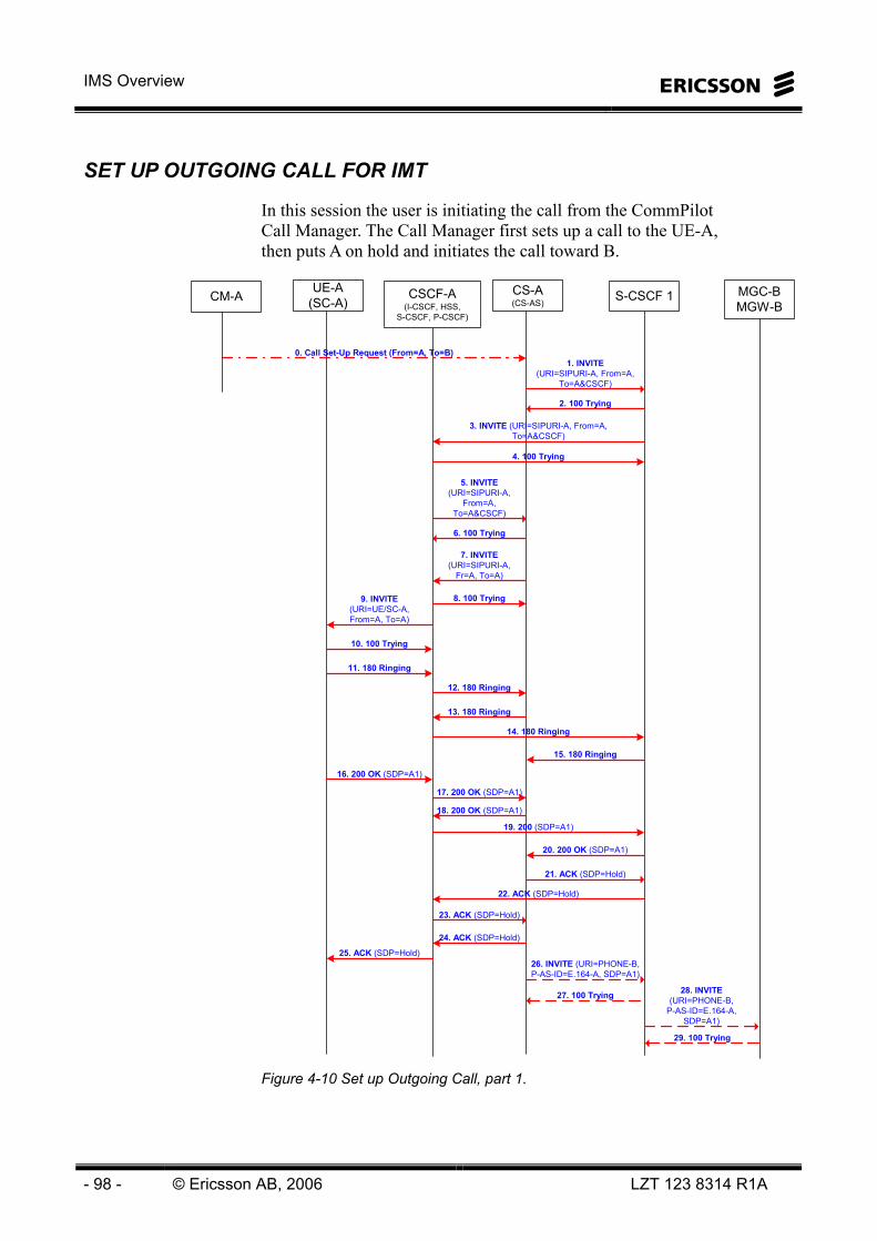
IMS Overview
- 98 - © Ericsson AB, 2006 LZT 123 8314 R1A
SET UP OUTGOING CALL FOR IMT
In this session the user is initiating the call from the CommPilot Call Manager. The Call Manager first sets up a call to the UE-A, then puts A on hold and initiates the call toward B.
1. INVITE(URI=SIPURI-A, From=A,
To=A&CSCF)
2. 100 Trying
4. 100 Trying
UE-A(SC-A)
CS-A(CS-AS)
MGC-BMGW-B
26. INVITE (URI=PHONE-B,P-AS-ID=E.164-A, SDP=A1)
27. 100 Trying
CSCF-A(I-CSCF, HSS,
S-CSCF, P-CSCF)
S-CSCF 1
3. INVITE (URI=SIPURI-A, From=A,To=A&CSCF)
5. INVITE(URI=SIPURI-A,
From=A,To=A&CSCF)
6. 100 Trying
8. 100 Trying
7. INVITE(URI=SIPURI-A,
Fr=A, To=A)
10. 100 Trying
9. INVITE(URI=UE/SC-A,From=A, To=A)
11. 180 Ringing
12. 180 Ringing
13. 180 Ringing
14. 180 Ringing
15. 180 Ringing
16. 200 OK (SDP=A1)
17. 200 OK (SDP=A1)
18. 200 OK (SDP=A1)
19. 200 (SDP=A1)
20. 200 OK (SDP=A1)
22. ACK (SDP=Hold)
23. ACK (SDP=Hold)
24. ACK (SDP=Hold)
25. ACK (SDP=Hold)
21. ACK (SDP=Hold)
28. INVITE(URI=PHONE-B,
P-AS-ID=E.164-A,SDP=A1)
29. 100 Trying
CM-A
0. Call Set-Up Request (From=A, To=B)
Figure 4-10 Set up Outgoing Call, part 1.

4 Multimedia Session Establishment
LZT 123 8314 R1A © Ericsson AB, 2006 - 99 -
0. The user A requests a call set up through the Call Manager's web interface. The request includes the address of the B-party and the UE-A that the subscriber wishes to use for the call.
1-2. The CS-AS initiates the set-up of a call leg towards the UE-A by sending an INVITE to a CSCF (CSCF 1), not necessarily the CSCF where A is currently is registered since the CS-AS-A does not hold this information (the CS-AS never receives the REGISTER message at registration). A's public SIP address is included in the URI, TO and FROM header. In addition, the TO header contains a proprietary parameter ("CSCF") used to indicate suppression of terminating services. The INVITE also contains A's SDP with codecs that are provisioned (statically) on the CS-AS-A.
3-4. The CSCF-1 forwards the INVITE message to the CSCF-A to which A has registered.
5-6. Based on the subscription trigger data stored in the CSCF-A (previously downloaded from the HSS-A at registration), it triggers the CS-AS-A.
7-8. Upon receiving the INVITE with a TO header with a suppression parameter ("cscf"), the CS-AS-A knows not to invoke terminating services. Instead it proxies the INVITE on to the CSCF-A.
9-10. The CSCF-A proxies the INVITE to the UE-A.
11-15. UE-A alerts the A-user and sends a Ringing message backwards to the CS-AS-A
16-20. A accepts the call, whereby a 200 OK is sent backwards to the CS-AS-A.
21-25. The CS-AS-A sends an ACK to the UE-A, including an SDP indicating that UE-A is put on hold (there is not yet a B party connected).
26-27. The CS-AS-A now initiates the set-up of the call leg towards the B-party (in this example an external E.164 number) by sending a new INVITE to the CSCF 1.
28-29. After ENUM query (system subscriber not found), the CSCF-1 proxies the INVITE to the MGC, which executes ISUP signaling towards B (not shown).

IMS Overview
- 100 - © Ericsson AB, 2006 LZT 123 8314 R1A
47. 200 OK (SDP=B1)
48. 200 OK (SDP=B1)
49. INVITE(SDP=B1&Resume)
50. INVITE (SDP=B1&Resume)
51. INVITE(SDP=B1&Resume)
52. INVITE(SDP=B1&Resume)
53. INVITE(SDP=B1&Resume)
54. 200 OK (SDP=A3)
55. 200 OK (SDP=A3)
56. 200 OK (SDP=A3)
57. 200 OK (SDP=A3)
58.200 OK (SDP=A3)
60. ACK
61. ACK
62. ACK
63. ACK
59. ACK
64. ACK (SDP=A3)
65. ACK (SDP=A3)
Both Way RTP Media (A3-B1)
37. 200 OK (SDP=A2)38. 200 OK (SDP=A2)
39. 200 OK (SDP=A2)
40. 200 OK (SDP=A2)
41. 200 OK (SDP=A2)
43. ACK
44. ACK
45. ACK46. ACK
42. ACK
30. 180 Ringing
31. 180 Ringing
32. INVITE(SDP=Ringback)
33. INVITE (SDP=Ringback)
34. INVITE(SDP=Ringback)
35. INVITE(SDP=Ringback)36. INVITE
(SDP=Ringback)
UE-A(SC-A)
CS-A(CS-AS)
MGC-BMGW-B
CSCF-A(I-CSCF, HSS,
S-CSCF, P-CSCF)
S-CSCF 1
Figure 4-11 Set up Outgoing Call, continued.
4 Multimedia Session Establishment
LZT 123 8314 R1A © Ericsson AB, 2006 - 101 -
30-31. When receiving an alerting indication from B, the MGC sends a 180 RINGING backwards via the CSCF-1 to the CS-AS-A.
32-36. The CS-AS-A now instructs the UE-A to play ring-back tones locally in the client by sending a (RE-) INVITE containing an SDP with ring-back indication to the UE-A.
37-46. The ring-back instruction is acknowledged by the UE-A.
47-48. When receiving an answer indication from B, the MGC sends a 200 OK backwards via the CSCF-1 to the CS-AS-A.
49-53. The CS-AS-A instructs the UE-A to resume the connection by sending a (RE-) INVITE containing an SDP with both-way trough-connect indication.
54-63. The through-connect instruction is acknowledged by the UE-A.
64-65. Finally, the 200 OK from B is acknowledged before both way media streams are established between the UEs.

IMS Overview
- 102 - © Ericsson AB, 2006 LZT 123 8314 R1A
1-1 POC SESSION SCENARIO
This is an instant personal talk with the auto answer and manual answer modes.
The user at UE#1: • Presses the PTT button;
• Receives a “beeping” signal when a media channel is established;
• The user starts to talk;
• Releases the PTT button;
• Receives a “beeping” sound that the floor is taken by the other user;
• Receives speech from the other user; and,
• Receives a beeping sound when the floor is idle again.
The user at UE#2: • In the case the UE#2 is configured for auto answer:
• Receives a “beeping” sound in the loud speaker;
• Listens to the user at UE#1 speech phrase;
• Receives a “beeping” sound that the floor is idle;
• Presses the PTT button;
• Receives a “beeping” sound that that the user can start to speak;
• The user talks; and,
• The user releases the PTT button;
In the case the UE#2 is configured for manual answer: • Receives a ringing signal and a accept talk invitation? Yes/No
prompt;
• Accepts talk invitation;
• Receives a “beeping” sound in the loud speaker;
• Listens to the user at UE#1 speech phrase;
• Receives a “beeping” sound that the floor is idle;
• Presses the PTT button;
• Receives a “beeping” sound that that the user can start to speak;
• The user talks; and,

4 Multimedia Session Establishment
LZT 123 8314 R1A © Ericsson AB, 2006 - 103 -
• The user releases the PTT button;
At expiry of the inactivity timer the PoC Server terminates the talk session.

IMS Overview
- 104 - © Ericsson AB, 2006 LZT 123 8314 R1A
Intentionally Blank

5 Operation and Maintenance
LZT 123 8314 R1A © Ericsson AB, 2006 - 105 -
5 Operation and Maintenance

IMS Overview
- 106 - © Ericsson AB, 2006 LZT 123 8314 R1A
Intentionally Blank

5 Operation and Maintenance
LZT 123 8314 R1A © Ericsson AB, 2006 - 107 -
INTRODUCTION The main O&M tools in IMS are: • Operation Support System (OSS), for supervision and
management of the IMS networks and nodes.
• Ericsson Multi-Activation (EMA), for the provisioning of subscribers and services in IMS.
OSS can provide a northbound interface to the operator’s overall Network Management system, using standard protocols and interfaces. See Figure 5-1.
- Open interfaces
Eve
nts
Sta
tistic
s
Com
mands
System or Multi-vendor Solution
Other Networks
BackboneNetwork
AccessAccessAccess
Servers
BackboneNetwork
AccessAccessAccess
Servers
BackboneNetwork
AccessAccessAccess
Servers
Events
Statistics
Com
mands
Sub-Network ManagementOSS-RC MN-OSS
Network Management System or Multi-vendor Solution
Other Networks
BackboneNetwork
AccessAccessAccess
Servers
BackboneNetwork
AccessAccessAccess
Servers
BackboneNetwork
AccessAccessAccess
Servers
BackboneNetwork
AccessAccessAccess
Servers
BackboneNetwork
AccessAccessAccess
Servers
BackboneNetwork
AccessAccessAccess
Servers
BackboneNetwork
AccessAccessAccess
Servers
Netw
ork Element Level
Figure 5-1 OSS Overview.
Ericsson Multi-Activation allows the user to manage subscribers and services using a single interface. Without EMA, the processes of defining or deleting a subscriber, adding services, or modifying a subscriber’s services, would require to access numerous individual nodes.
This chapter will describe the features of MN-OSS and EMA in overview. The various tools will be described so that the reader will understand their purpose and their place in the overall O&M function.

IMS Overview
- 108 - © Ericsson AB, 2006 LZT 123 8314 R1A
MN-OSS Multi-service Network Operation Support System (MN-OSS) provides four main management functions: • Configuration Management.
• Fault Management.
• Performance Management.
• Security Management.
MN-OSS allows the O&M user to monitor and supervise the entire IMS network; to view the alarm status of the network and of individual nodes; to examine in detail the alarms of each individual nodes and to process these alarms; to perform detailed performance measurements in the network; to access the element manager interface for all supported elements; to search for historical alarm data and other tasks.
CONFIGURATION MANAGEMENT
Provisioning or configuration of the network is required to optimize the quality of the service provided to the end-user. It is realized through launching of the Element Managers (EM) within the individual network nodes. The EMs provide controlled and detailed configuration of the network. They can be launched directly from any of the management tools within MN-OSS.
PERFORMANCE MANAGEMENT
ANALYZER is the core performance application. It assists the operator in short-term surveillance of network performance and provides reliable statistics for long-term network planning. This allows the operator to foresee bottlenecks and assure quality of service.
Analyzer collects measurement data from the network elements and aggregates this data according to a user definable data model. The results are then placed in a third party relational database from which they can be retrieved by other applications.
SECURITY MANAGEMENT
Security Management at the network element level provides these functions: • Administration of end user profiles.
5 Operation and Maintenance
LZT 123 8314 R1A © Ericsson AB, 2006 - 109 -
• System administrator and normal user roles are supported through the O&M toolbox.
• A normal user can be configured to gain access in read-only, read-write or no-access to various parts of the system.
• Authorization of access administration of end user profiles.
• Ability to configure the maximum number of login attempts before an account is locked. A notification is raised when an account is locked. The event is logged and an alarm is raised.
• Logging facilities to record all user activities and all access attempts to the network elements.
FAULT MANAGEMENT
Fault Management is provided by the Ericsson Fault Manager, which includes the following tools: • Geographical and logical Network Information Presentation
(GNIP).
• Alarm Status Matrix.
• Alarm List Viewer.
• Alarm Log Browser.
The Ericsson Fault Manager (EFM) provides an integrated view of the IMT network, showing its status in real time. It makes the operator aware of network problems, gives support for decisions on how to handle a situation, and how to take corrective action.
SUPPORTED IMT NODES
Server and Session Control Nodes
HSS - Home Subscriber Server CSCF - Call Session Control Function CSAS - Centrex Services Application Server CSMS - Media Server CSCS - Conference Server CSDS - Distribution Server CSWS - Web Server PS - Presence Server

IMS Overview
- 110 - © Ericsson AB, 2006 LZT 123 8314 R1A
O&M and Support Nodes
FE - Front End Server ENUM DNS - Domain Name Server Netscreen - Firewall Extreme Summit - L3 Switch MM - MultiMediation EMA - Ericsson Multi-Activation
Inter-working Nodes
MGC - Media Gateway Controller MGW - Media Gateway SC - Session Controller
MN-OSS HARDWARE
MN-OSS is a Unix system with Sun Solaris 9 servers, see Figure 5-2.
Unix Application Server- Citrix Metaframe- Client Applications
Windows/Unix Citrix ClientsShared printer
Windows 2003 Report Server
Unix environment- Sun Server- Solaris 9
Figure 5-2 Hardware architecture.
The Application Server includes the Citrix Metaframe. The Citrix Metaframe is software, which supports the “application server computing” in which the application runs in the server for multiple users. Only screen changes in the user interface are sent to the individual client machines. The core technology in this Metaframe is the ICA (Independent Computing Architecture) protocol, which governs the input/output between client and server.
The thin clients run Citrix ICA Client software.
The Analyzer Report Server is implemented in a Windows 2003 platform.

5 Operation and Maintenance
LZT 123 8314 R1A © Ericsson AB, 2006 - 111 -
THE MN-OSS DESKTOP
The MN-OSS tools can be started from the MN-OSS Applications Menu or from the MN-OSS Workspace Menu. The later is accessed by right-clicking on the desktop.
Figure 5-3 MN-OSS Desktop.
When selecting OSS Network Explorer a common Graphical User Interface (GUI) for the MN-OSS tools will open, see Figure 5-4.
Figure 5-4 OSS Network Explorer (ONE).
The purpose of ONE is to improve accessibility and visibility of the different support functions for the O&M activities in the network.
The functions included in ONE are: • Launching applications

IMS Overview
- 112 - © Ericsson AB, 2006 LZT 123 8314 R1A
• Creating a network view
• Editing a network view
• Deleting a network view
• Finding a network object
• Dragging and dropping network objects
• Audit-trail logging
It can be configured which network objects are visible in the topology tree and which applications can be launched for the respective network object.

5 Operation and Maintenance
LZT 123 8314 R1A © Ericsson AB, 2006 - 113 -
MN-OSS LIBRARY
Active Library Explorer (ALEX) provides a means to browse Ericsson documents with a standard web browser, see Figure 5-5.
ALEXweb based user documentation
Figure 5-5 MN-OSS library, Alex
The Alex Toolbar allows the user to search for documents/keywords, change libraries, print documents, change user preferences and other functions.
When the Alex library is selected, the contents are displayed on the left, and the user can select a section, for example ‘Operation -> Fault Management User Guides-> Ericsson Fault Manager’. The right-hand window shows all the documents available in this section, from which the user can choose.
There are User Guides and System Administrator Guides for the various tools. The User Guides describe each tool in detail, explaining common tasks, menus, commands, and use.
Alex has a simple conventional search function, to search the library for key words. The user types in key words and clicks the search button.
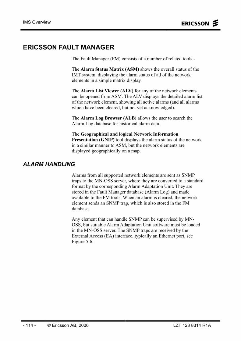
IMS Overview
- 114 - © Ericsson AB, 2006 LZT 123 8314 R1A
ERICSSON FAULT MANAGER The Fault Manager (FM) consists of a number of related tools -
The Alarm Status Matrix (ASM) shows the overall status of the IMT system, displaying the alarm status of all of the network elements in a simple matrix display.
The Alarm List Viewer (ALV) for any of the network elements can be opened from ASM. The ALV displays the detailed alarm list of the network element, showing all active alarms (and all alarms which have been cleared, but not yet acknowledged).
The Alarm Log Browser (ALB) allows the user to search the Alarm Log database for historical alarm data.
The Geographical and logical Network Information Presentation (GNIP) tool displays the alarm status of the network in a similar manner to ASM, but the network elements are displayed geographically on a map.
ALARM HANDLING
Alarms from all supported network elements are sent as SNMP traps to the MN-OSS server, where they are converted to a standard format by the corresponding Alarm Adaptation Unit. They are stored in the Fault Manager database (Alarm Log) and made available to the FM tools. When an alarm is cleared, the network element sends an SNMP trap, which is also stored in the FM database.
Any element that can handle SNMP can be supervised by MN-OSS, but suitable Alarm Adaptation Unit software must be loaded in the MN-OSS server. The SNMP traps are received by the External Access (EA) interface, typically an Ethernet port, see Figure 5-6.

5 Operation and Maintenance
LZT 123 8314 R1A © Ericsson AB, 2006 - 115 -
TSPIPWorks
AXDAlarmAdaptationUnit
MN-OSS
EAFMH
(FM Kernel)
AutomaticAcknowledge
AutomaticAcknowledge
FileFileGNIP, ASV, ASM
FMA DBFMA DB
ALV
ALB SRD
PrinterPrinter
Figure 5-6 Ericsson Fault Manager.
Alarms from different network elements may have different structures and may contain different types of information. All alarms are converted to a standard structure by their corresponding Alarm Adaptation Unit software in the MN-OSS server, before being stored in the Alarm Log database.
The standard structure consists of a number of fields, or Attributes, in a certain order. The incoming alarm data is mapped to these Attributes. Examples of Attributes are Perceived Severity, Object of Reference (That is, the name of the element which generated the alarm), Event Time and so on. The format of a standard alarm is shown in Figure 5-7.
Some Attributes can be changed or added to by the user. For example, when the user acknowledges the alarm, the Attributes Acknowledger and Acknowledge Time are updated. Also when a user adds a comment to the alarm, the new comment is added to the Attribute Comments, keeping a history of the actions taken to clear the alarm.

IMS Overview
- 116 - © Ericsson AB, 2006 LZT 123 8314 R1A
Figure 5-7 Standard Alarm Format.
LINK SUPERVISION
If a network element has a problem communicating with the MN-OSS server, it will be unable to send new alarms and the MN-OSS Alarm Status view will not be updated. The element may or may not be working correctly.
In order to check communication with the network elements, the MN-OSS server sends periodic SNMP Heartbeat traps to each element. See Figure 5-8.
If the server receives a reply to the trap, it knows that communication is up. If no reply is received, the MN-OSS assumes contact is lost and displays a heartbeat alarm on ASM or GNIP.

5 Operation and Maintenance
LZT 123 8314 R1A © Ericsson AB, 2006 - 117 -
Link SupervisionLink Supervision
Heart Beat
HB SupervisionHB Supervision
NE
Figure 5-8 Link Supervision.
If MN-OSS loses contact with a network element, new alarms and alarms clearing will not be communicated to the server. Over a period of time the MN-OSS Alarm Log will become inaccurate.
When communication is up again, the Alarm Log and the alarm lists of each network element must be synchronized. Any alarms received which are not in the Alarm Log will be added, also any alarms which exist in the Alarm Log but which are not received during synchronization, will be marked as Cleared. Synchronization is performed automatically by MN-OSS.
NE1
NEFMA DB
NE1
NE
NE1
NEFMA DBFMA DB
The Alarm list at the NE1 site
The Alarm list of NE1 in FM
SNMP
Figure 5-9 Synchronization.
The user can also order manual synchronization at any time, from any FM tool.

IMS Overview
- 118 - © Ericsson AB, 2006 LZT 123 8314 R1A
THE ALARM STATUS MATRIX (ASM) The Alarm Status Matrix (ASM) is launched from the Alarm menu in ONE. The view consists of a matrix of cells; each cell displaying the status of a network element, or Managed Object, see Figure 5-10.
Figure 5-10 ASM main view.
The ASM views can be adapted regarding for example displayed objects, amount of rows and columns, level of displayed alarms and so on. Once a view is defined it can be saved, so that it is automatically displayed next time ASM is launched.
Each Cell displays the Supervision Status and Alarm Status of the Managed Object.
The total number of active alarms of each severity is shown at the bottom of the cell, and the total number of Not Acknowledged active alarms is shown at the top. The color of each square shows the severity.
ASM displays the overall alarm status of each element. To view the alarms on a particular element in detail, click on the cell to select the element and open the Alarm List Viewer.

5 Operation and Maintenance
LZT 123 8314 R1A © Ericsson AB, 2006 - 119 -
THE ALARM LIST VIEWER (ALV) The Alarm List Viewer (ALV) is launched from the Alarm menu in ONE or from ASM or GNIP.
The ALV displays all active alarms, from the MN-OSS Alarm Log database, see Figure 5-11.
The alarms are displayed in an Alarm List Frame within the ALV window, and the Alarm List Frames can be configured in many ways in order to suit the requirements of the user. In this section, some of the most common options will be described.
ALV actions -View alarms and alarm detailsAcknowledge (or Unacknowledge) alarmsFilter alarm informationAdd personal comments to the alarmsPrint/Store/Mail/Copy alarm informationAccess to other MN-OSS applications
ALV actions -View alarms and alarm detailsAcknowledge (or Unacknowledge) alarmsFilter alarm informationAdd personal comments to the alarmsPrint/Store/Mail/Copy alarm informationAccess to other MN-OSS applications
Figure 5-11 ALV, with one Alarm List Frame.
Figure 5-11 shows the alarm status of the specified element. The top field shows all active and cleared but Not Acknowledged alarms. There are eight cleared alarms, shown by the ‘C’ in the first column and two active alarms – one Minor and one Warning.
The eight cleared alarms are displayed because they are Not Acknowledged, although they have been cleared on the element. When these alarms are examined and acknowledged, they will disappear from the list. This ensures that short duration; perhaps repetitive alarms are not overlooked.

IMS Overview
- 120 - © Ericsson AB, 2006 LZT 123 8314 R1A
Within each Alarm List Frame there can be several Alarm Lists displayed, each with different filters applied. The default is to have one ‘field’ - ‘Alarm List 1’ showing all active and cleared but Not Acknowledged alarms. The other field - ‘Alarm List 2’ is filtered and displays only the Acknowledged alarms. Other Alarm Lists can be defined with filters, for example – filter only alarms that have been acknowledged by user ‘erasnpt’. Note that these are just different views of the same Alarms from the Alarm Log.
It is possible to have more than one Alarm List Frame displayed, each displaying alarms for a different element. See Figure 5-12.
List frame 1
Static List
Frame
Dynamic List
Frame
List frame 2
Alarm List 1
Alarm List 2
Figure 5-12 Configuration of ALV.

5 Operation and Maintenance
LZT 123 8314 R1A © Ericsson AB, 2006 - 121 -
GNIP AND ALARM STATUS VIEWER The Geographical and Logical Network Presentation Tool (GNIP) is an alternative way of presenting an overview of the Alarm Status of the complete network, in a similar way to the Alarm Status Matrix.
GNIP displays the network elements in their geographical position on a map and the user can zoom in to see more detail about the elements and where they are located.
GNIP also provides a Logical View, where the elements are displayed on a blank background and can be arranged hierarchically in a structured view.
GNIP has three databases – one that stores the map files, one that stores the symbols, which are displayed on the map, and one that stores Views. A view consists of: • map, zoom level and position. • symbols/network elements • alarm detail level
The actual alarm detail is supplied by the Alarm Status Viewer.
A Geographical View is shown in Figure 5-13, which shows a map, with two network elements presented.
Map database
Map database
Symbol databaseSymbol
database
Views database
Views database
GNIPApplication
GNIPApplication
GNIPApplication
GNIPApplication
Figure 5-13 GNIP Overview.
Figure 5-14 shows a Logical View.
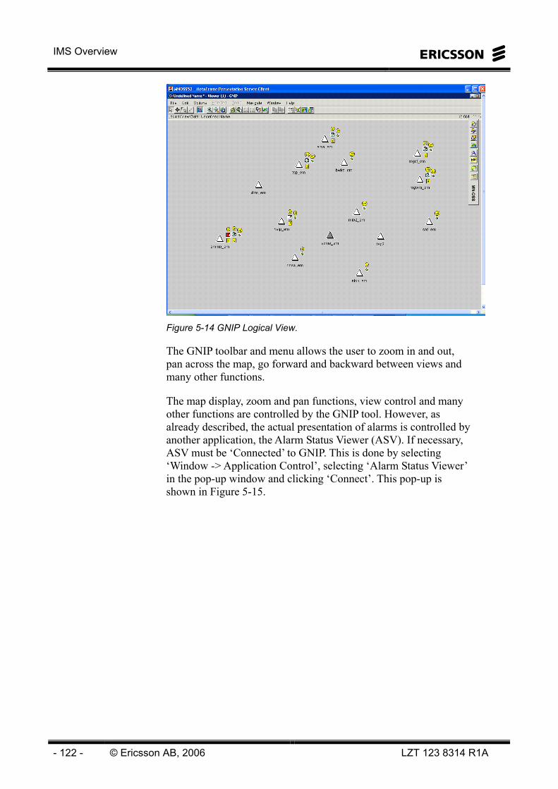
IMS Overview
- 122 - © Ericsson AB, 2006 LZT 123 8314 R1A
Figure 5-14 GNIP Logical View.
The GNIP toolbar and menu allows the user to zoom in and out, pan across the map, go forward and backward between views and many other functions.
The map display, zoom and pan functions, view control and many other functions are controlled by the GNIP tool. However, as already described, the actual presentation of alarms is controlled by another application, the Alarm Status Viewer (ASV). If necessary, ASV must be ‘Connected’ to GNIP. This is done by selecting ‘Window -> Application Control’, selecting ‘Alarm Status Viewer’ in the pop-up window and clicking ‘Connect’. This pop-up is shown in Figure 5-15.

5 Operation and Maintenance
LZT 123 8314 R1A © Ericsson AB, 2006 - 123 -
Figure 5-15 GNIP Application and View Control.
The user can also change the view settings by selecting ‘View Control’ from the same menu. The ‘View Control’ pop-up appears as also shown in Figure 5-15. Here the user can select – • Which Objects to display.
• Which Map set to use, and the level of detail in the map (roads, rail, borders, coast…).
• Which Presentation Rule to use (In Symbol, All Alarms, Highest Alarms only, Alarm numbers…).
• The Tool Administrator also has a fourth tab – which allows the definition of additional presentation rules.
These options are again fully described in the GNIP and ASV User Guides.

IMS Overview
- 124 - © Ericsson AB, 2006 LZT 123 8314 R1A
THE ALARM LOG BROWSER (ALB) As explained earlier, all active alarms and alarms that have been cleared are stored in a common format in the Fault Manager database, also known as the Alarm Log. Information such as date and time of alarm, network element name, name of acknowledger, comments added and so on, is also stored in each alarm record.
The Alarm Log database should be regularly maintained and backed up by the System Administrator, to ensure it does not increase to an unmanageable size.
The Alarm Log Browser allows the user to search the Alarm Log for individual alarm records, or alarm statistics, using any of the alarm attributes.
For example, the user could search alarm records for –
‘All alarms with ‘PerceivedSeverity’ Critical on the ‘Object of Reference’ TSP which occurred in the past 7 days’.
The user can also search for alarm statistics, for example –
‘How many alarms of each severity occurred every hour last week?’
There is a Wizard and a Tabs interface. This section describes the Tabs.

5 Operation and Maintenance
LZT 123 8314 R1A © Ericsson AB, 2006 - 125 -
Figure 5-16. ALB tabs interface.
A Filter can narrow the search based on any of the Alarm Attributes. For example –
• Find all alarms with Attribute PerceivedSeverity = Critical.
• Find all alarms with Attribute Acknowledger = eric.
If no search Filters are to be applied, all alarms from the defined managed objects, which occurred during the specified timescales will be found and displayed.
The user must specify the type of output (individual alarms or alarm statistics) and for the choice ‘individual alarms’, which attributes are to be displayed for each alarm found during the search.
IMS Overview
- 126 - © Ericsson AB, 2006 LZT 123 8314 R1A
Figure 5-17 ALB search type and attributes.
Finally the output format is defined. To see the individual alarms with one attribute per line, select ‘Expanded’.
If the result is to be saved to a file for opening in another application such as ‘Word’ or ‘PowerPoint’, ‘Tab separated’ is selected.
‘Standard Alarm text’ is an internal Fault Manager format.
5 Operation and Maintenance
LZT 123 8314 R1A © Ericsson AB, 2006 - 127 -
AXD OPERATION SUITE AXD Operations Suite (AOS) is a family of management applications developed by Ericsson. AOS integrates several management applications into a unified management framework, based on industry standards such as Simple Network Management Protocol (SNMP), as well as other technologies, like Java, CORBA, and so on. The currently available AOS applications are: • PMR - Performance Monitor
• ACT - AXD Configuration Tool
• AMD - Alarm Mediation Device
• TMG - Test Manager
The functions of the AOS applications cover the following areas of management: fault management, configuration management, performance management, and accounting management. Also, AOS provides functions needed in a service provider scenario, such as customer service management, and end-to-end service configuration and activation.
BASE
The BASE subsystems include Security Management, Audit Trail, and the Topology Manager: • Security Management is a common function shared by all
AOS applications, providing authentication and access information to its users.
• Audit Trail is a common function providing a means of tracking network management actions. Actions affecting the network and the most important AOS activities are registered in the Audit Trail log. Integration of the AOS applications enables this operation; independently from whether the action is performed using one of the AOS applications mentioned above, or AXD 301/305 is accessed directly through its web browser interface. In this case, log files have to be queried from the AXD manually.
• The Topology Manager is a common function to collect topology data and inventory from the network element Management Information Bases (MIBs), and it supplies other applications with this information. The basis topology object types are nodes, ports, connections, and vital resources (within individual nodes).

IMS Overview
- 128 - © Ericsson AB, 2006 LZT 123 8314 R1A
Figure 5-18 Base Overview.
PERFORMANCE MONITOR
Performance Monitor (PMR) is designed for the easy collection of a wide range of network performance measurement data, allowing for the powerful presentation and effective analysis of measurement results.
PMR provides the user with the following features: • Gathering network element configuration
• Setting up data normal or real-time collection jobs
• Setting up measurement configurations
• Initiating data collection
• Storing data in the PMR database
• Generating alarms on threshold violation
• Generating XML reports
• Presenting data received from the database
• Analyze received data
• Several report options
PMR supports all measurement types, instances, and counters in AXD.

5 Operation and Maintenance
LZT 123 8314 R1A © Ericsson AB, 2006 - 129 -
Network Information DisplayMenu Bar
Log Area
Work Area Information Area
Figure 5-19 Performance Monitor.
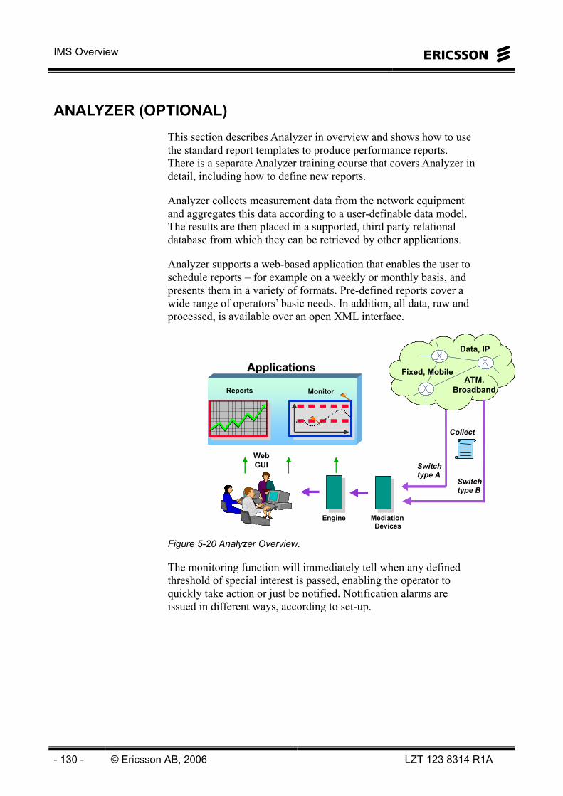
IMS Overview
- 130 - © Ericsson AB, 2006 LZT 123 8314 R1A
ANALYZER (OPTIONAL) This section describes Analyzer in overview and shows how to use the standard report templates to produce performance reports. There is a separate Analyzer training course that covers Analyzer in detail, including how to define new reports.
Analyzer collects measurement data from the network equipment and aggregates this data according to a user-definable data model. The results are then placed in a supported, third party relational database from which they can be retrieved by other applications.
Analyzer supports a web-based application that enables the user to schedule reports – for example on a weekly or monthly basis, and presents them in a variety of formats. Pre-defined reports cover a wide range of operators’ basic needs. In addition, all data, raw and processed, is available over an open XML interface.
Collect
Switch type B
Switch type A
Mediation Devices
Engine
Reports Monitor
Fixed, Mobile
Data, IP
ATM, Broadband
WebGUI
ApplicationsApplications
Figure 5-20 Analyzer Overview.
The monitoring function will immediately tell when any defined threshold of special interest is passed, enabling the operator to quickly take action or just be notified. Notification alarms are issued in different ways, according to set-up.

5 Operation and Maintenance
LZT 123 8314 R1A © Ericsson AB, 2006 - 131 -
Figure 5-21 Examples of Analyzer reports.
The Analyzer application has a modular architecture and consists of the following sub-components: -
Mediation – specific mediation applications are available for the individual technologies supported by the network. Examples are SNMP, FTP and CORBA. The data is converted into a common format used within Analyzer.
Aggregation – The raw data coming from the network is processed and written to a data model based on the rules defined in the aggregation engine. The aggregation engine has a GUI interface that may be used to by users to define their own data models.
Report Server and Applications – Analyzer incorporates a sophisticated reporting tool that allows for scheduling and distribution of reports. Reports can be ordered for delivery at specific times and can be output in a wide range of formats. Possible report destinations include mail, printer or ftp server.
Monitoring – The analyzer Monitoring application can be used to set thresholds. When a threshold is exceeded, an alarm is generated and can be sent to EFM or to another fault manager. Thresholds can be defined on the raw data coming from the network or can be based on the processes data in the database.
Interfaces – Analyzer supports both XML and CSV formats, for export of performance data for use by northbound systems.
Alarms from the Monitoring function can be forwarded via SNMP, X.733, BNSI or Flat file.
IMS Overview
- 132 - © Ericsson AB, 2006 LZT 123 8314 R1A
Supported Nodes
The IPMM PM Application supports the following nodes in EMM2.1 - ICSCF, SCSCF, PCSCF, HSS, Presence Server, Application Server, Media Server, Conference Server and MGC.
Report Server
The ANALYZER Report Server is a product for scheduling and viewing performance and service management reports based on aggregated data from a network. The basic functions are provided by a Crystal Enterprise Web based reporting tool.
Reports from the Report Server can be exported in a number of formats including Excel, Word, Acrobat, Rich Text, Plain Text, TSV and CSV.
The Report Server Package includes the following pre-defined reports for MultiMedia.
1 Multimedia Traffic Summary
2 Multimedia Nodes Peak Period
3 Multimedia Nodes Statistics
4 Multimedia Traffic Characteristics Summary
5 Multimedia Traffic Characteristics Failure Statistics
6 BroadWorks Application Server Error Statistics
7 BroadWorks Media Server MCP Statistics
8 BroadWorks Media Server RTP Statistics
9 Conference Manager Requests Statistics
10 System’s CPU and Memory Utilization Statistics
11 Service Invocation
12 Resource Access Management
13 Cx Characteristics Summary
14 SS7 Signaling Data link Statistics - Top X
The main functions of the ANALYZER Report Server are accessed through the Web Browser.
A typical scenario of a Report Server is shown in Figure 5-22.

5 Operation and Maintenance
LZT 123 8314 R1A © Ericsson AB, 2006 - 133 -
Figure 5-22 Report Server.

IMS Overview
- 134 - © Ericsson AB, 2006 LZT 123 8314 R1A
PROVISIONING FOR IMT Provisioning is typically an act when a new subscription for a specific end-user should be activated. Provisioning details vary from service to service but in general they encompass four actions for every entity involved. A system must be able to list, add, delete and modify the data describing the subscribers and related attributes.
The IMS Multimedia Telephony (IMT) solution supports a layered structure for hierarchical role based service provisioning and administration, which enable operators, enterprises and residential users to provision and administrate services in an efficient way. The five layers are: • System Provider (Whole seller)
• Service Provider (Retailer) & Large Enterprise
• Enterprise / Business Group
• Department Administrator
• User
Depending on the access authority, the user will be given access to different parts of the provisioning system. See Figure 5-23.
Figure 5-23 Provisioning Roles for IMT.

5 Operation and Maintenance
LZT 123 8314 R1A © Ericsson AB, 2006 - 135 -
ROLES
System Provider
The System Provider role provides access to all of the system monitoring, maintenance, provisioning, and configuration functions. This role is allowed to perform the following: • Define service providers and large enterprises
• Administration of multiple service providers in case of wholesale scenario
• Assigning addressing and number ranges etc. for service providers
• Define services packages and restrictions in number of service instances etc. for each service provider/large enterprise
Figure 5-24 Opening Screen for System provider.

IMS Overview
- 136 - © Ericsson AB, 2006 LZT 123 8314 R1A
Service Provider
One or several Service Providers can use the system. Each Service Provider consists of one or several Groups. The Service Provider is acting as a virtual operator through the buying of capacity from the system provider. In the system, the service provider can only access parts that are related to management of the customers of that specific service provider. The service provider does not have access to system monitoring or maintenance functions, but is allowed to do this: • Administration of multiple customers, e.g. define SME
customers
• Define addressing schemes and number ranges for Business groups
• Services packages for each Enterprise / SME customer
• Define service restrictions and e.g. number of service instances for each Enterprise / SME customer
Large Enterprise
The Large Enterprise is an extension of the Service Provider role, where an administrator can manage a big sized company in the same way a Service Provider manage customers. The additional authorizations of a Large Enterprise are: • Manage hierarchical departments residing directly under the LE
root, in which users can belong to
• Assign location codes to LE groups
Group
The Group concept is used in the system to group users of the same type, and enable the provisioning of all services common to that group. Examples of such services are short number dialing, control the access to directory information and enterprise phone book.
Business Groups Enterprise end-users belong to a business group. Larger enterprises can optionally further split the users of a group into multiple departments. The end-users inside a business group can perform white pages searches of the other group members’ data using the PC client.
Residential Group Residential users are grouped into one or several groups.
5 Operation and Maintenance
LZT 123 8314 R1A © Ericsson AB, 2006 - 137 -
Open and Closed Groups A group can be open (public) or closed (private). An open group implies that it is searchable for external end-users while a closed group is accessible only by its own members. The SRD stores the information regarding the group’s open/close state.
User
The Personal web portal allows the users to view, configure, activate and deactivate their respective subscribed services. The user has only access to the services that are assigned to that user by the administrator. The personal web portal would typically be used for offline service configuration, i.e. configuring of services when the end-user is not involved in a call or session.
The personal web portal also provides the users with: • List of user subscribed services
• List of subscribed group services
• Context-sensitive help for every service
• Feature access codes that are associated with subscribed-to services.
Normally the user would activate, de-activate and configure services via the personal web portal. However, the services can also be managed via feature access codes, i.e. * key combinations, on a physical terminal.
PROVISIONING ENTITIES
There are three different ways of provisioning in IMT: • Classic provisioning – provisioning via a Customer
Administration System (CAS) (for operators/service providers)
• Self Provisioning – provisioning through the Broadworks/FE Web interface (for service providers, enterprise/residential customers and end-users)
• VPN Provisioning – provisioning of VPN data through EMA Web interface (for operators)
There are four nodes that are provisioning access points in the solution; the EMA system used as the main interface for the operators CAS. The CS-WS, the FE, and the SRD are combined to provide provisioning support for non-operator provisioning activities. Nodes that are indirectly involved in the provisioning flow are the CS-AS and the CS-DS.

IMS Overview
- 138 - © Ericsson AB, 2006 LZT 123 8314 R1A
SOBH: Service Order Batch Handler
FE
Figure 5-25 Provisioning Nodes for IMT.

5 Operation and Maintenance
LZT 123 8314 R1A © Ericsson AB, 2006 - 139 -
Ericsson Multi Activation (EMA)
The Ericsson Multi Activation (EMA) classic system provides external Business Support Systems (e.g. Customer Administration Systems) with a CAI (Customer Administration Interface) based interface for provisioning of subscriber data. EMA hides the distribution of subscriber data to multiple entities and provides one uniform interface (CAI/CAI3G) through which all databases can be accessed.
All end-users and groups, with the data that is required, are created, modified, retrieve and deleted using the EMA.
Additionally, EMA contains a CS-AS Reporting Receiver (CS-AS RR). The task of the CS-AS RR is to distribute CS-AS data that has been updated using the web-client to the other nodes in the system. When subscriber data has been modified, the CS-AS sends a notification to the EMA CS-AS RR. The EMA CS-AS RR then collects the updated information from the CS-AS before updating the other nodes using the CAI interface.
A VPN Web GUI is provided to manage the VPN data. This GUI is to be used by operators only.
The EMA distributes all required provisioning data to the following network elements:
System Repository and Directory (SRD) Destination of supplied data when users, groups, group administrators, and department administrators are provisioned.
Centrex Services Application Server (CS-AS) Destination of supplied data when users, groups, group administrators, departments, and department administrators are provisioned.
ENUM Domain Name Service (ENUM DNS) Destination of supplied data when users are provisioned.
Presence Server (PS) Destination of supplied data when users are provisioned.
Home Subscriber Server (HSS) Destination of supplied data when users are provisioned.

IMS Overview
- 140 - © Ericsson AB, 2006 LZT 123 8314 R1A
The EMA interworking interfaces are standardized as can be seen in Figure 5-26.
EMACS-AS
ENUMDNSHSS
SRD
PS
XML/CORBA
RMI
LDAPv3
LDAPv3CLI/TELNET
CORBA: Common Object Request Broker Archhitecture RMI: Remote Method InvocationLDAP: Lightweight Directory Access Protocol XML: Extensibel Markup LanguageSRD: System Reposity Directory CLI: Command Line InterfaceCAS: Customer Administration System CAI: Customer Administration Interface
CAS
CAI/CAI3G
EMAEMACS-ASCS-AS
ENUMDNSHSSHSS
SRDSRD
PSPS
XML/CORBA
RMI
LDAPv3
LDAPv3CLI/TELNET
CORBA: Common Object Request Broker Archhitecture RMI: Remote Method InvocationLDAP: Lightweight Directory Access Protocol XML: Extensibel Markup LanguageSRD: System Reposity Directory CLI: Command Line InterfaceCAS: Customer Administration System CAI: Customer Administration Interface
CASCAS
CAI/CAI3G
Figure 5-26 EMA Interworking for IMT.
CLASSIC PROVISIONING
In Classic Provisioning EMA gets provisioning orders from the CAS through the CAI or CAI3G, as seen above.
It is the system provider that has access to the CAI and CAI3G. In addition, the system provider has the possibility to give access for service providers or large enterprises to manage the CAI and CAI3G.
For Classic Provisioning, EMA offers a stand-alone application for control and execution of batch files, the Service Order Batch Handler (SOBH). The purpose of batch handling is to automate handling of large amounts of subscriptions, so called bulk provisioning.
The following can be created, modified, and deleted when conducting Classical provisioning: • Service providers and administrators
• Large enterprises and administrators
• Groups and administrators
• Departments and administrators
• End-users
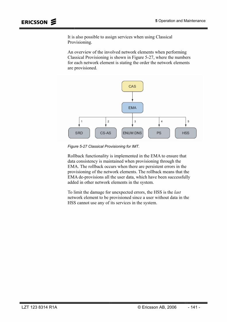
5 Operation and Maintenance
LZT 123 8314 R1A © Ericsson AB, 2006 - 141 -
It is also possible to assign services when using Classical Provisioning.
An overview of the involved network elements when performing Classical Provisioning is shown in Figure 5-27, where the numbers for each network element is stating the order the network elements are provisioned.
Figure 5-27 Classical Provisioning for IMT.
Rollback functionality is implemented in the EMA to ensure that data consistency is maintained when provisioning through the EMA. The rollback occurs when there are persistent errors in the provisioning of the network elements. The rollback means that the EMA de-provisions all the user data, which have been successfully added in other network elements in the system.
To limit the damage for unexpected errors, the HSS is the last network element to be provisioned since a user without data in the HSS cannot use any of its services in the system.
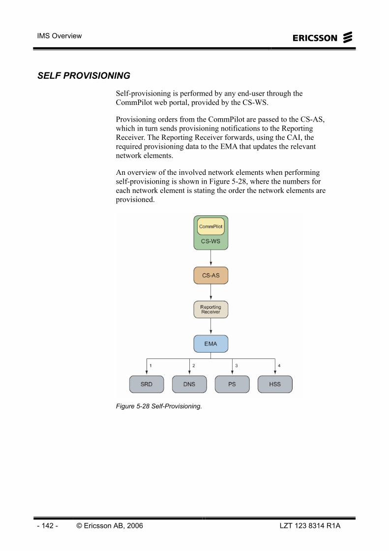
IMS Overview
- 142 - © Ericsson AB, 2006 LZT 123 8314 R1A
SELF PROVISIONING
Self-provisioning is performed by any end-user through the CommPilot web portal, provided by the CS-WS.
Provisioning orders from the CommPilot are passed to the CS-AS, which in turn sends provisioning notifications to the Reporting Receiver. The Reporting Receiver forwards, using the CAI, the required provisioning data to the EMA that updates the relevant network elements.
An overview of the involved network elements when performing self-provisioning is shown in Figure 5-28, where the numbers for each network element is stating the order the network elements are provisioned.
Figure 5-28 Self-Provisioning.

5 Operation and Maintenance
LZT 123 8314 R1A © Ericsson AB, 2006 - 143 -
The following can be created, modified, and deleted when conducting self provisioning: • Service providers
• Large enterprises
• Groups
• Group administrators
• Departments
• Department administrators
• End-users

IMS Overview
- 144 - © Ericsson AB, 2006 LZT 123 8314 R1A
PROVISIONING FOR MOBILE IMS The different nodes to be provisioned for IMS Push To Talk and IMS weShare within IMS are: • Home Subscriber Service (HSS)
• PoC Server
• Domain Name Server
• Presence and Group List Management Server
• Automatic Device Configuration
For IMS Push To Talk, Ericsson IMS provides a Web UDM with Internet access as well as an interface towards the terminal for user data management of groups, contacts, screening settings etc. Both the Web UDM and the terminal use the XCAP protocol to access the network, see Figure 5-29.
Figure 5-29 Provisioning for Mobile IMS.
Ericsson Multi Activation supports provisioning of HSS, through a LDAP interface, in IMS with the following manageable objects:
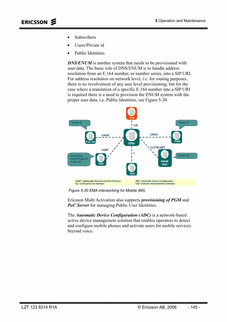
5 Operation and Maintenance
LZT 123 8314 R1A © Ericsson AB, 2006 - 145 -
• Subscribers
• Users/Private id
• Public Identities
DNS/ENUM is another system that needs to be provisioned with user data. The basic role of DNS/ENUM is to handle address resolution from an E.164 number, or number series, into a SIP URI. For address resolution on network level, i.e. for routing purposes, there is no involvement of any user level provisioning, but for the case where a translation of a specific E.164 number into a SIP URI is required there is a need to provision the ENUM system with the proper user data, i.e. Public Identities, see Figure 5-30.
EMAEMAPoC AS
ENUMDNSHSSHSS
PGM
ADC
CAI3G
?LDAP
CLI/TELNET
LDAP: Lightweight Directory Access Protocol ADC: Automatic Device ConfigurationCLI: Command Line Interface CAI: Customer Administration Interface
CASCAS
CAI
CAI3G
•Subscriber•User/Private ID•Public ID
•Public ID
•Public ID
•Public ID
Figure 5-30 EMA interworking for Mobile IMS.
Ericsson Multi Activation also supports provisioning of PGM and PoC Server for managing Public User Identities.
The Automatic Device Configuration (ADC) is a network-based active device management solution that enables operators to detect and configure mobile phones and activate users for mobile services beyond voice.

IMS Overview
- 146 - © Ericsson AB, 2006 LZT 123 8314 R1A
Intentionally Blank

6 Glossary
LZT 123 8314 R1A © Ericsson AB, 2006 - 147 -
6 Glossary

IMS Overview
- 148 - © Ericsson AB, 2006 LZT 123 8314 R1A
3GPP 3rd Generation Partnership Project.
See http://www.3gpp.org/About/about.htm
ABG Access Border Gateway.
ACT AXD Configuration Tool An application included in the Ericsson AOS.
Active Contacts Client
A software SIP client that provides presence, instant messaging, audio, and video calls.
ADC Automatic Device Configuration
AF Assured Forwarding DiffServ Class of service, which is used for traffic less sensitive to delay and delay variation, and that can be buffered to get low-loss. Used for voice signalling and multimedia signalling.
ALB Alarm Log Browser, an application in MN-OSS.
ALEX Active Library Explorer. Provides a means for a user to browse Ericsson document libraries with a standard web browser.
ALV Alarm List Viewer, an application in MN-OSS.
AMS AXD Management System A built-in Element Manager for the AXD 301, used for O&M of the MGW.
ANALYZER A set of applications in the MN-OSS used for performance management, which provides useful information in short time, as well as longtime network and business planning.
AOS AXD Operations Suite An extended Element Manager for the AXD 301, comprising a collection of applications used for the O&M of the MGW.
API Application Program Interface
ARP Address Resolution Protocol. Internet protocol used to map an IP address to a Medium Access Control address. It allows host computers and routers to determine the data link layer addresses through the ARP Request and ARP Response process. Defined in IETF RFC 826.

6 Glossary
LZT 123 8314 R1A © Ericsson AB, 2006 - 149 -
AS Application Server. Offers value added IP Multimedia services and resides, either in the user’s home network or in a third party location. The third party could be a network or simply a stand alone AS. Defined in 3GPP TS 23.002.
A-SBG Access Session Boarder Gateway Placed between an access network and the system, to funnel sessions from user agent clients (UAC) to the CSCF
A-SC Access Session Controller ACME name for A-SBG
ASM. Alarm Status Matrix
ASV Alarm Status Viewer, an application in the MN-OSS.
ATM Asynchronous Transfer Mode Asynchronous Transfer Mode is an ITU-T standard for cell relay wherein information for multiple service types, such as voice, video, or data, is conveyed in small, fixed-size cells.
AUC Authentication Center The Authentication Centre is an entity which stores data for each mobile subscriber to allow the IMSI to be authenticated and to allow communication over the radio path between the mobile station and the network to be ciphered. Defined in 3GPP TS 23.002.
AXD301 Ericsson Media Gateway platform
B2BUA Back-to-Back User Agent. A logical entity that receives a request and processes it as a UAS. In order to determine how the request should be answered, it acts as a UAC and generates requests. Defined in IETF RFC 3261.
BA Border Agent Name of Ericsson's product, part of MGC.
BG Border Gateway.
BGP Border Gateway Protocol A routing protocol. BGP-4 is the latest version, defined in IETF RFC 1771 and IETF RFC 1772.
BRAS BroadBand Access System
BSS Business Support System
CAI Customer Administration Interface A CMISE-like and ASCII-based protocol, transmitted over X.25 or TCP/IP, which is used for provisioning.

IMS Overview
- 150 - © Ericsson AB, 2006 LZT 123 8314 R1A
CAP Client Authentication Protocol. For call control from the web client to the CS-AS in the CS subsystem
CAS Customer Administration System A dedicated business support system for administrating customers.
CCP Call Control Protocol. For call control from the web client to the CS-AS in the CS subsystem
CD Common Directory
CDMA Code Division Multiple Access A multiplexing scheme over radio channels. Data intended for a specific channel is modulated with that channels code.
CDO Charging Data Output.
CDR Charging Data Record A formatted collection of information about a chargeable event (for instance, time of call setup, duration of the call, amount of data transferred and so on) for use in billing and accounting. Sometimes referred to as Call Detail Record. Defined in 3GPP TR 21.905.
CLI Command Line Interface A means of communication between a program and its user, based solely on textual input and output.
CommPilot The CommPilot is a web-based client for management and provisioning of the offered end-user services and it is launched by means of a Uniform Resource Locator (URL) pointing at the Web Server (CS-WS), part of the Application Server (CS-AS), in the CS subsystem.
CORBA Common Object Request Broker Architecture An architecture and specification for creating, distributing, and managing distributed program objects in a network.
CS Centrex Services
CS-AS The Centrex System Application Server is the core entity of the CS subsystem and the main access point for control signaling.
CSCF Call Session Control Function The core node in IMS, using SIP as the signaling protocol.
CS-CS Centrex System Conference Server Provides conferencing features, including web-based presentation and collaboration.

6 Glossary
LZT 123 8314 R1A © Ericsson AB, 2006 - 151 -
CS-DS Centrex Services Distribution Server At web-login, the CS-DS provides the address of the hosting CS-AS of a given user to the CS-WS.
CSI 3GPP Combinational Services Specification
CS-MS Centrex System Media Server Provides specialized media resources including digit detection, announcement playback and recording, and media mixing functions such as 3-party call conferencing.
CSS Call Screening Server
CSV Comma Separated Variable
CS-WS Centrex Services Web Server Provides a web-interface towards the CS-AS for operator provisioning and end-user self-provisioning of the CS-AS services.
DHCP Dynamic Host Configuration Protocol A protocol that provides a means to dynamically allocate IP addresses to computers on a local area network.
Diameter The Diameter base protocol is intended to provide an AAA framework for applications such as network access or IP mobility, specified in IETF RFC 3588.
DiffServ Differentiated services Intended to provide a framework and building blocks to enable deployment of scalable service discrimination in the Internet. Defined in RFC 2474 and RFC 2475.
DMZ De-Militarized Zone A computer host or small network inserted as a neutral zone between a private network and the outside public network. It prevents outside users from getting direct access to a server in a private network.
DNS Domain Name System A network of databases that translates Internet domain names into IP addresses. Defined in IETF STD 13, RFC 1034 and RFC 1035.
DSCP DiffServ Code Point
E.164 International Public Telecommunication Numbering Plan as described in the ITU-T Recommendation E.164. The 15-digit number is split into international, national, and user number portions.
E1 The E1 signal format carries data at a rate of 2048 kbps. It carries 32 channels of 64 kbps each.
IMS Overview
- 152 - © Ericsson AB, 2006 LZT 123 8314 R1A
EAS Ericsson Application Server
eDNS External Domain Name System.
EF Expedited Forwarding DiffServ Class of Service that provides a low-loss, low-jitter, low-delay handling of packets. It is used for real time voice and conversational multimedia.
EFM Ericsson Fault Manager (MN-OSS)
EIT Ericsson Instant Talk A VoIP application that offers easy-to-use half-duplex push to talk voice communication
EM Element Manager
EMA Ericsson Multi Activation Used for provisioning. The system receives provisioning information from CAS and distributes data towards affected network elements.
EMM Engine Multimedia An end-to-end network solution, enabling delivery of advanced multimedia services and content over fixed broadband networks using IP technology.
EMP Ericsson Mobile Platform
ENUM A protocol resulting from the work of the IETF Telephone Number Mapping working group. It is defined in IETF RFC 2916 and provides a DNS based architecture and protocols for mapping a telephone number to URI. The URI can be used to contact a resource associated with that number.
Ericsson IMS Common System
A core IP multimedia system that complements Ericsson’s existing wireless and wireline solutions, providing transparency between fixed Next Generation Networks and mobile 2,5G/3G communication services. .
FAC Feature Access Code The code dialed to access a subscriber feature
FE Front End Web server which authenticates users and interrogates SRD to redirect user to the correct CS Web server.
FMX Fault Management eXpert, an application in the MN-OSS.
FQDN Fully Qualified Domain Name The full name of a system, consisting of its local host name and its domain name, including a top-level domain.

6 Glossary
LZT 123 8314 R1A © Ericsson AB, 2006 - 153 -
FTP File Transfer Protocol As defined in IETF RFC 959 and IETF STD0009.
G.711 An international standard for encoding telephone audio on a 64 kbps channel. It is a PCM scheme operating at an 8 kHz sample rate, with 8 bits per sample.
G.723.1 An ITU-T recommendation for a Dual Rate Speech Coder for Multimedia Communications Transmitting at 5.3 kbps and 6.3 kbps.
G.726 ITU-T recommendation for ADPCM coding at 16, 24, 32, and 40 kbps.
G.729 ITU-T recommendation about an 8 kbps speech coder.
GGSN Gateway GPRS Support Node
GNIP Geographical & Logical Network Presentation (MN-OSS)
GPRS General Packet Radio Service A packet linked technology that enables high speed wireless Internet and other data communication.
Group A predefined set of PoC users that is identified by a SIP URI. A PoC client uses the Group to establish PoC sessions and to define PoC session access policy.
H.248 Also known as the MeGaCo protocol. H.248 is the standard for allowing an MGC to control an MGW. H.248 represents a joint effort between the ITU-T and the IETF. This protocol is considered complementary to H.323 and SIP in that an MGC will control MGWs using H.248, but will communicate using H.323 or SIP.
H.261 A video coding standard. It was designed to suit ISDN lines with data rates which are multiples of 64 kbps.
H.263 A standard that supports video compression for video conferencing and video telephony applications.
H.323 A standard approved by the ITU to promote compatibility in video conference transmissions over IP networks.
HLR Home Location Register The Home Location Register is the main database of permanent subscriber information for a mobile network. Specified in 3GPP TS 23.002

IMS Overview
- 154 - © Ericsson AB, 2006 LZT 123 8314 R1A
HSS Home Subscriber Server The master database for a given user. It is the entity containing the subscription-related information to support the network entities actually handling calls and sessions. Defined in 3GPP TS 23.002.
HTTP Hypertext Transfer Protocol An application-level protocol for distributed, collaborative, hypermedia information systems, as defined in IETF RFC 2616.
HTTPS Hypertext Transfer Protocol over TLS Defined in IETF RFC 2817 and RFC 2818.
IAD Integrated Access Device. Performs A to D speech conversion and DTMF to SIP signaling conversion. Allows ‘traditional’ phones to connect to IMT network.
ICA Independent Computing Architecture
ICP IMS Client Platform
I-CSCF Interrogating CSCF The entry point for all connections destined to a subscriber of that network operator. The I-CSCF assigns an S-CSCF during initial registration and routes the terminating session signaling to the allocated S-CSCF.
iDNS Internal Domain Name System.
IEEE Institute of Electrical and Electronics Engineers. .
IETF Internet Engineering Task Force The IETF is the body that defines standard Internet operating protocols such as TCP/IP.
IMS IP Multimedia Subsystem The standard defines a generic architecture for offering VoIP and multimedia services. For users, IMS based services enable person-to-person and person-to-content communications in a variety of modes, including voice, text, pictures, and video. Defined in 36PP TS 23.228.
IMS AS IMS Application Server
IMSM IMS Messaging
IMT IMS MultiMedia Telephony

6 Glossary
LZT 123 8314 R1A © Ericsson AB, 2006 - 155 -
IP Internet Protocol A network layer protocol of TCP/IP responsible for addressing and sending TCP packets over the network.
IP Centrex
IPMM IP Multimedia A core IP multimedia system, providing transparency between fixed Next Generation Networks and mobile 3G communication services.
IPSec IP Security.
IPWorks A software platform that provides DNS and DHCP services for IPv4 and IPv6 networks. IPWorks also includes an element management system for configuration and control of these services.
IS Framework Integrated Site Framework (“Blade”)
ISDN Integrated Services Digital Network A set of CCITT and ITU standards for digital transmission over ordinary telephone copper wire as well as over other media.
ISUP ISDN User Part Defines the protocol and procedures used to set up, manage and release trunk circuits that carry voice and data calls over the PSTN. ISUP is used for both ISDN and non-ISDN calls
ITU-T International Telecommunication Union – Telecommunication Standardization Sector.
IVR Interactive Voice Response A software application that accepts a combination of voice telephone input and touch-tone keypad selection and provides appropriate responses in the form of voice, fax, callback, e-mail, and perhaps other media.
LAES Lawfully Authorized Electronic Surveillance. IMT provides a LAES implementation that complies with the J-STD-025 standard
LDAP Lightweight Directory Access Protocol. A protocol for accessing online directory services. Defined by the IETF.
LE Local Exchange
LI-IMS Lawful Intercept – Intercept Management System
LNP Local Number Portability

IMS Overview
- 156 - © Ericsson AB, 2006 LZT 123 8314 R1A
Location Server The logical unit within the HSS that keeps track of which S-CSCF a user is registered at.
M3UA MTP3 User Adaptation Layer A protocol for supporting the transport of any SS7 MTP3-User signaling over the IP Network. Defined in IETF RFC 3332.
MeGaCo Manager (MGM)
Media Gateway Controller Manager The O&M tool of the MGC.
MGC Media Gateway Controller A node that provides the signaling level interworking function between circuit switched telephone network and packet switched multimedia networks.
MGW (MG) Media Gateway Interfaces the media plane of the PSTN or Circuit Switched (CS) network. The MGW is able to send and receive IMS media over the RTP. To connect the CS network the MGW uses one or more PCM time slots. Specified in 3GPP TS 23.002.
MIB Management Information Base A database of objects monitored by a network management system.
MIME Multipurpose Internet Mail Extensions An extension of the original Internet e-mail protocol that lets people use the protocol to exchange different kinds of data files on the Internet.
MM Ericsson Multi Mediation The Ericsson Multi Mediation is used for accounting management. The system receives charging information from network elements, processes it and forwards it as necessary.
MN-OSS Multi-Service Networks Operational Support System The Network Management system used for fault and performance management. It is also used to access the different element managers.
MPLS Multi Protocol Label Switching Developed to speed up the transmission of IP based communications over ATM networks.
MRF Media Resource Function
MRFC Media Resource Function Controller
MRFP Media Resource Function Processor Responsible for multi-party session control
MRFP Media Resource Function Proxy for WeShare

6 Glossary
LZT 123 8314 R1A © Ericsson AB, 2006 - 157 -
MSC Mobile Services Switching Centre
MSC Server MSC Server Used to control wireless circuit switched traffic
MSG Multi-Service Gateway
MSRP Message Session Relay Protocol Image and media File Protocol
MTP Message Transfer Part Forms part of the SS7 protocol stack and provides reliable routing usually within a network.
NAT Network Address Translator A method by which IP addresses are mapped from one realm to another, in an attempt to provide transparent routing to hosts. Defined in IETF RFC 2663.
N-SBG Network Session Boarder Gateway Placed between an external network and the system, to funnel sessions from external networks to the CSCF.
N-SC Network Session Controller
O&M Operation and Maintenance
OMA Open Mobile Alliance Mission: to facilitate global user adoption of mobile data services by specifying market driven mobile service enablers that ensure service interoperability across devices, geographies, service providers, operators, and networks, while allowing businesses to compete through innovation and differentiation. See www.openmobilealliance.org
ONE OSS Network Explorer
ORB Object Request Broker Within an object based communication system, an ORB keeps track of the actual addresses of all defined objects and thus is used to route traffic to the correct destination. The CORBA defines the ORB in a series of standards enabling different platforms to share common information.
OTAP Over The Air Provisioning.
PBX Private Branch Exchange Allows a small number of outside lines to be shared among all of the people of an organization. Also known as PABX.

IMS Overview
- 158 - © Ericsson AB, 2006 LZT 123 8314 R1A
P-CSCF Proxy Call Session Control Function An IMS element that identified as the mobiles first contact point within the IP Multimedia Core Network subsystem. Functions of the P-CSCF include the forwarding of SIP messages received from the UE. Defined in 3GPP TS 23.002
PDSN Packet Data Service Node Provides mobile nodes with IP Connectivity and IP session continuity within CDMA2000 on both public and private IP networks.
PGM Presence, Group & List Management An Ericsson product that can be hosted on the EAS. Presence can be seen as a dynamic profile of status information for persons, applications or machines that is visible to others. The Group and List Management feature in the PGM server enables a user to define and administer lists such as contact lists, access lists and group member lists from the UE. It also provides the ability for a user to organize contacts, define groups, and define incoming call settings.
PMR Performance Monitor An AOS application that is used for collecting, storing, and presenting performance data from the MGW.
PoC Push-to-Talk over Cellular An IMS based application that is available in the wireless network. PoC offers feature-rich services for person-to-person and group communication, including do-not-disturb settings, transparency and presence management.
PoC AS PoC Application Server A dedicated server for the Ericsson IMS Push To Talk service
POP3 Post Office Protocol version 3 A standard protocol for receiving E-mail, as defined in IETF RFC 1939.
Presence Information that describes the status of the end-user, of the client software that the end-user is currently running, or of the device that the end-user is running his client on.
Private User Identity
Every user in the IP Multimedia network has a Private Identity. The Private Identity is assigned by the home domain operator, and used, for example, for registration, authorization, administration, and accounting purposes. Defined in 3GPP TS 23.003.
PS Presence Server

6 Glossary
LZT 123 8314 R1A © Ericsson AB, 2006 - 159 -
PSTN Public Switched Telephone Network This is a general term referring to the variety of telephone networks and services.
PTT Push to Talk A walkie-talkie type of service. Users press (and hold) a button when they want to say something, but they do not start speaking until their terminal tells them to do so (usually by beeping).
Public User Identity
The public identity is used within the home domain of IP Multimedia network to uniquely identify the user profile.
QoS Quality of Service The idea that transmission rates, error rates, and other characteristics can be measured, improved, and, to some extent, guaranteed in advance.
RADIUS Remote Authentication Dial In User Service A system of distributed security that secures remote access to networks and network services against unauthorized access. Defined in IETF RFC 2865.
Registrar A server that accepts REGISTER (for example the S-CSCF) requests and places the information it receives in those requests into the location service for the domain it handles.
RFC Request For Comment A formal document from the IETF. It is the result of committee drafting and subsequent review by interested parties.
RNC Radio Network Controller
Route Header Field
A SIP header field, containing an ordered list of SIP URI for SIP proxies through which SIP request should be routed.
RTCP RTP Control Protocol RTP combines its data transport with a RTCP, which makes it possible to monitor data delivery. Defined in IETF RFC 3550.
RTP Real Time Transport Protocol An Internet protocol standard that defines a way for applications to manage the real-time transmission of multimedia data. Defined in IETF RFC 3550.
RTSP Real Time Streaming Protocol An application-level protocol for control over the delivery of data with real-time properties as defined in IETF RFC 2326.
SBC Session Border Controller (ACME)
SBG Session Border Gateway Ericsson’s product; used at Edge, Core or Border interface.

IMS Overview
- 160 - © Ericsson AB, 2006 LZT 123 8314 R1A
S-CSCF Serving CSCF Performs the session control services for the endpoint. This includes routing of originating sessions to external networks and routing of terminating sessions to visited networks. Defined in 3GPP TS 23.002.
SDS Service Development Studio A toolset for building applications that can be deployed on the EAS.
SFTP Secure FTP. Belongs to SSHv2 suite of tools and can replace insecure FTP.
SIMPLE SIP for Instant Messaging and Presence Leveraging Extensions.
SIP Session Initiation Protocol A signaling protocol for creating, modifying and terminating sessions with one or more participants, as defined in IETF RFC 3261.
SIP Server A SIP Server is a network element that receives requests in order to service them and sends back responses to those requests. Examples of servers are proxies, user agent servers, redirect servers, and registrars. Defined in IETF RFC 3261.
SIP Session A multimedia session is a set of multimedia senders and receivers and the data streams flowing from senders to receivers. A multimedia conference is an example of a multimedia session. As defined, a caller can be invited several times, by different calls, to the same session. If SDP is used, a session is defined by the concatenation of the SDP user name, session ID, network type, address type, and address elements in the origin field. Defined in IETF RFC
SIP URI A type of Uniform Resource Identifier that identifies a communication resource in SIP. A SIP URI usually contains a user name and a host name and is similar in format to an e-mail address. Defined in IETF RFC 3261.
SIP User Agent A SIP endpoint involved in SIP signaling, defined in IETF RFC 3261.
SME Small / Medium Enterprise
SMTP Simple Mail Transfer Protocol The IETF standard management protocol for TCP/IP networks. Defined in IETF RFC 821.
SNMP Simple Network Management Protocol Part of the TCP/IP suite and is used to control and manage IP gateways and other network functions. Defined in IETF RFC 1157.

6 Glossary
LZT 123 8314 R1A © Ericsson AB, 2006 - 161 -
SOBH Service Order Batch Handler
SQL Structured Query Language A standard interactive and programming language for getting information from and updating a database.
SRD System Repository and Directory Enables operators to hold end user data for users, in order to make these data easily available via an LDAP interface.
SS7 Signaling System No 7 Used in many modern telecoms networks and provides a suite of protocols which enables circuit and non circuit related information to be routed about and between networks. Defined by the ITU-T.
SSL Secure Socket Layer A commonly-used protocol for managing the security of a message transmission on the Internet.
Stateful Proxy A logical entity that maintains the client and server transaction state machines defined by this specification during the processing of a request, also known as a transaction stateful proxy. A transaction stateful proxy is not the same as a call stateful proxy.
Stateless Proxy A logical entity that does not maintain the client or server transaction state machines defined in this
Static Route A route in the network router configuration that is manually configured by the network administrator.
T1 A digital interface at 1544 kbps. It carries 24 PCM signals using TDM.
TAS Telephony Application Server
TCP Transmission Control Protocol A reliable octet streaming protocol used by the majority of applications on the Internet. It provides a connection-oriented, full-duplex, point to point service between hosts. Defined in IETF RFC 793.
TDM Time Division Multiplexing A method in which a transmission facility is multiplexed among a number of channels by allocating the facility to the channels on the basis of time slots.
Tel URI Telephony Uniform Resource Identifier.
Telnet Telnet is a protocol for remote terminal connection service, as defined in IETF RFC 854.

IMS Overview
- 162 - © Ericsson AB, 2006 LZT 123 8314 R1A
TelORB Telephone Object Request Broker An Ericsson propriety operating system. It is a CORBA compliant, distributed real-time processing environment, providing a robust cluster based platform for telecom applications.
TISPAN Telecoms & Internet converged Services & Protocols for Advanced Networks. TISPAN is responsible in ETSI for all aspects of standardization for present and future converged networks, including Voice over IP (VoIP), Next Generation Networks (NGN). See http://portal.etsi.org/portal_common/home.asp?tbkey1=TISPAN
TMG Test Manager (MN-OSS)
TSP Ericsson Telecom Server Platform.
TSV Tab Separated Variable
UA User Agent An endpoint in a SIP based network.
UAC User Agent Client In VoIP, a client application in a SIP system that initiates the SIP request that is sent to the UAS. The combination of the UAC and the UAS is called the SIP User Agent. The SIP user agent allows peer-to-peer calls to be made using a client-server protocol. Defined in IETF RFC 3261.
UAS User Agent Server In VoIP, a server application in a SIP system that accepts the requests from a UAC and generates an accept, reject, or redirect response on behalf of the user. The combination of the UAC and the UAS is called the SIP User Agent. The SIP user agent allows peer-to-peer calls to be made using a client-server protocol. Defined in IETF RFC 3261.
UDM User Data Manager
UDP User Datagram Protocol Part of the TCP/IP Protocol suite, a standard, connectionless, host-to-host protocol that is used over packet-switched computer communications networks. UDP is typically used for real time applications. Defined in IETF RFC 768.
UE User Equipment A device allowing a user access to network services. Defined in 3GPP TR 21.905.

6 Glossary
LZT 123 8314 R1A © Ericsson AB, 2006 - 163 -
URI Uniform Resource Identifier A compact string of characters for identifying an abstract or physical resource. Defined in IETF RFC 2396.
URL Uniform Resource Locator A standard way of specifying the location of an object, typically a web page, on the Internet. URL is the form of address used on the WWW. Defined in IETF RFC 2396.
vCard A proposed standard for personal data interchange, specifically electronic business cards. vCards are often attached to e-mail messages, but can be exchanged in other ways, such as on the web. They can contain name and address information, phone numbers, URLs, logos, photographs, and even audio clips.
VoIP Voice over IP A system enabling voice data to be delivered using the IP. It is sometimes referred to as IP telephony.
VPN Virtual Private Network A private network link, which is carried on a public network through the use of tunneling. It is likely that the communication will utilize encryption techniques.
VXML Voice eXtensible Markup Language.
WAV Windows audio WAVE form file format.
WCDMA Wideband Code Division Multiple Access.
WeShare A combinational service that provides the users with an instant way of sharing images, video streams, whiteboard, or some other media while speaking in a voice call conversation.
WLAN Wireless LAN
WS WeShare
WSN Wireless Service Node. For wireless LANs
XCAP XML Configuration Access Protocol A protocol defined by IETF that maps the components of XML documents (sub-trees, elements and attributes) to URIs, so that these components can be directly accessed via HTTP. XCAP allows a client application to read, write and modify application configuration data using HTTP GET, PUT and DELETE methods.
XML eXtensible Markup Language.

IMS Overview
- 164 - © Ericsson AB, 2006 LZT 123 8314 R1A
Intentionally Blank